FS100 INSTRUCTIONS - MRO Electric
373
YASKAWA ELECTRIC CORPORATION MANUAL NO. RE-CTO-A219 2 FS100L INSTRUCTIONS Upon receipt of the product and prior to initial operation, read these instructions thoroughly, and retain for future reference. MOTOMAN INSTRUCTIONS (FOR LARGE AND MEDIUM-SIZED MANIPULATORS) MOTOMAN- INSTRUCTIONS FS100L INSTRUCTIONS FS100L OPERATOR’S MANUAL FS100L MAINTENANCE MANUAL The FS100 OPERATOR’S MANUAL above is applicable to both FS100 and FS100L controllers.
-
Upload
khangminh22 -
Category
Documents
-
view
7 -
download
0
Transcript of FS100 INSTRUCTIONS - MRO Electric

FS100L INSTRUCTIONS
Upon receipt of the product and prior to initial operation, read these instructions thoroughly, and retain for future reference.
MOTOMAN INSTRUCTIONS
(FOR LARGE AND MEDIUM-SIZED MANIPULATORS)MOTOMAN- INSTRUCTIONSFS100L INSTRUCTIONSFS100L OPERATOR’S MANUALFS100L MAINTENANCE MANUAL
The FS100 OPERATOR’S MANUAL above is applicable to both FS100 and FS100L controllers.
YASKAWA ELECTRIC CORPORATION
MANUAL NO. RE-CTO-A219 2

MANDATORY
• This manual explains setup, diagnosis, maintenance, hardware, etc. of the FS100L system. Read this manual carefully and be sure to understand its contents before handling the FS100L.
• General items related to safety are listed in chapter 1 “Safety” at page 1-1. To ensure correct and safe operation, carefully read the chapter.
CAUTION
• Some drawings in this manual are shown with the protective covers or shields removed for clarity. Be sure all covers and shields are replaced before operating this product.
• The drawings and photos in this manual are representative examples and differences may exist between them and the delivered product.
• YASKAWA may modify this model without notice when necessary due to product improvements, modifications, or changes in specifications. If such modification is made, the manual number will also be revised.
• If your copy of the manual is damaged or lost, contact a YASKAWA representative to order a new copy. The representatives are listed on the back cover. Be sure to tell the representative the manual number listed on the front cover.
• YASKAWA is not responsible for incidents arising from unauthorized modification of its products. Unauthorized modification voids your product’s warranty.
ii

Notes for Safe OperationRead this manual carefully before installation, operation, maintenance, or inspection of the FS100L .
In this manual, the Notes for Safe Operation are classified as “DANGER”, “WARNING”, “CAUTION”, “MANDATORY”, or “PROHIBITED”.
Even items described as “CAUTION” may result in a serious accident in some situations.
At any rate, be sure to follow these important items.
DANGERIndicates an imminent hazardous situation which, if not avoided, could result in death or serious injury to personnel.
WARNINGIndicates a potentially hazardous situation which, if not avoided, could result in death or serious injury to personnel.
CAUTIONIndicates a potentially hazardous situation which, if not avoided, could result in minor or moderate injury to personnel and damage to equipment. It may also be used to alert against unsafe practices.
MANDATORYAlways be sure to follow explicitly the items listed under this heading.
PROHIBITEDMust never be performed.
NOTETo ensure safe and efficient operation at all times, be sure to follow all instructions, even if not designated as “DAN-GER”, “WARNING” and “CAUTION” .
iii

WARNING
• Confirm that no person is present in the manipulator’s operating range and that you are in a safe location before:
– Turning ON the FS100L power.
– Moving the manipulator with the programming pendant.
– Running the system in the check mode.
– Performing automatic operations.
Injury may result if anyone enters the manipulator’s operating range during operation. Always press the emergency stop button immediately if there is a problem. The emergency stop button is located on the right of the programming pendant.
• Observe the following precautions when performing teaching operations within the manipulator’s operating range:
– Be sure to use a lockout device to the safeguarding when going inside. Also, display the sign that the operation is being performed inside the safeguarding and make sure no one closes the safeguarding.
– View the manipulator from the front whenever possible.
– Always follow the predetermined operating procedure.
– Keep in mind the emergency response measures against the manipulator’s unexpected motion toward you.
– Ensure that you have a safe place to retreat in case of emergency.
Improper or unintended manipulator operation may result in injury.
• Before operating the manipulator, check that servo power is turned OFF when the emergency stop button on the programming pendant is pressed. When the servo power is turned OFF, the SERVO ON LED on the programming pendant is turned OFF.
Injury or damage to machinery may result if the emergency stop circuit cannot stop the manipulator during an emergency. The manipulator should not be used if the emergency stop button does not function.
Fig. : Emergency Stop Button
• In the case of not using the programming pendant, be sure to supply the emergency stop button on the equipment. Then before operating the manipulator, check to be sure that the servo power is turned OFF by pressing the emergency stop button. Connect the external emergency stop button to the 5-6 pin and 16-17 pin of the robot system signal connector (CN2).
• Upon shipment of the FS100L, this signal is connected by a jumper cable in the dummy connector. To use the signal, make sure to supply a new connector, and then input it.
If the signal is input with the jumper cable connected, it does not function, which may result in personal injury or equipment damage.
iv

Definition of Terms Used Often in This ManualThe MOTOMAN is the YASKAWA industrial robot product.
The MOTOMAN usually consists of the manipulator, the FS100L controller, manipulator cables, the FS100L programming pendant (optional), and the FS100L programming pendant dummy connector (optional).
In this manual, the equipment is designated as follows:
WARNING
• Once the emergency stop button is released, clear the cell of all items which could interfere with the operation of the manipulator. Then turn the servo power ON.
Injury may result from unintentional or unexpected manipulator motion.
Fig. : Release of Emergency Stop Button
TURN
CAUTION
• Perform the following inspection procedures prior to conducting manipulator teaching. If a problem is found, correct it and take all other necessary actions immediately.
– Check for problems in manipulator movement.
– Check for damage to insulation and sheathing of external wires.
• Return the programming pendant to a safe place after use.
If the programming pendant is inadvertently left on the manipulator, on a fixture, or on the floor, the manipulator or a tool may collide with the programming pendant during manipulator movement, which may result in personal injury or equipment damage.
• Read and understand the Explanation of the Warning Labels before operating the manipulator.
Equipment Manual Designation
FS100L controller FS100L
FS100L programming pendant Programming pendant
Cable between the manipulator and the controller
Manipulator Cable
FS100L programming pendant dummy connector
Programming pendant dummy connector
v

Descriptions of the programming pendant, buttons, and displays are shown as follows:
Description of the Operation ProcedureIn the explanation of the operation procedure, the expression “Select • • • ” means that the cursor is moved to the object item and the SELECT key is pressed, or that the item is directly selected by touching the screen.
Registered TrademarkIn this manual, names of companies, corporations, or products are trademarks, registered trademarks, or brand names for each company or corporation. The indications of (R) and TM are omitted.
Equipment Manual Designation
ProgrammingPendant
Character Keys The keys which have characters printed on them are denoted with [ ].e.g. [ENTER]
Symbol Keys The keys which have a symbol printed on them are not denoted with [ ] but depicted with a small picture.
e.g. PAGE key
The cursor key is an exception, and a picture is not shown.
Axis KeysNumeric Keys
“Axis keys” and “Numeric keys” are generic names for the keys for axis operation and number input.
Keys Pressed Simultaneously
When two keys are to be pressed simultaneously, the keys are shown with a “+” sign between them.
e.g. SHIFT key + COORD key
Mode Key Three kinds of modes that can be selected by the mode key are denoted as follows:REMOTE, PLAY, or TEACH
Button Three buttons on the upper side of the programming pendant are denoted as follows:HOLD buttonSTART buttonEMERGENCY STOP button
Displays The menu displayed in the programming pendant is denoted with { }.e.g. {JOB}
PC Keyboard The name of the key is denoted.e.g. Ctrl key on the keyboard
GO BACK
PAGE
SHIFTTOOL SEL
COORD
vi

Explanation of Warning LabelsThe following warning labels are attached to the manipulator and FS100L.
Fully comply with the precautions on the warning labels.
DANGER
• The label described below is attached to the manipulator.
Observe the precautions on the warning labels.
• Failure to observe this caution may result in injury or damage to equipment.
Refer to the manipulator manual for the warning label location.
• The following warning labels are attached to FS100L.
Observe the precautions on the warning labels.
Failure to observe this warning may result in injury or damage to equipment.
WARNINGDo not enterrobot work area.
WARNINGMoving partsmay causeinjury
CAUTION
HOT SURFACE
Do not touch.
Electric Shock Warning NP
WARNING
High VoltageDo not open the cover.
Top View
Left Side View
Right Side View
Right Side View(Without the right panel)
Front View
Breaker
Back View
Risk of electric shock. Turn power of before removing the panel.
WARNING
vii

Contents
1 Safety .............................................................................................................................................. 1-1
1.1 For Your Safety.................................................................................................................. 1-1
1.2 Special Training ................................................................................................................. 1-2
1.3 Motoman Manual List.........................................................................................................1-2
1.4 Personnel Safety................................................................................................................1-3
1.5 Motoman Safety................................................................................................................. 1-5
1.5.1 Installation and Wiring Safety ...............................................................................1-5
1.5.2 Work Area Safety................................................................................................ 1-10
1.5.3 Operation Safety.................................................................................................1-11
1.6 Notes for Moving and Transferring MOTOMAN............................................................... 1-15
1.7 Notes on MOTOMAN Disposal ........................................................................................ 1-16
2 Product Confirmation ......................................................................................................................2-1
2.1 Contents Confirmation ....................................................................................................... 2-1
2.2 Order Number Confirmation...............................................................................................2-2
3 Installation....................................................................................................................................... 3-1
3.1 Handling Procedure ........................................................................................................... 3-1
3.1.1 When Using a Crane ............................................................................................3-1
3.1.2 When Using a Forklift ........................................................................................... 3-2
3.2 Place of Installation............................................................................................................3-3
3.3 Installation Location ........................................................................................................... 3-4
3.4 Installation Method.............................................................................................................3-5
4 Connection...................................................................................................................................... 4-1
4.1 Notes on Cable Connection ...............................................................................................4-3
4.2 Power Supply..................................................................................................................... 4-4
4.2.1 Three-Phase Power Supply..................................................................................4-4
4.2.2 Noise Filter Installation .........................................................................................4-4
4.2.3 Leakage Breaker Installation ................................................................................4-5
4.2.4 Primary Power Supply Breaker Installation .......................................................... 4-6
4.3 Connection Methods.......................................................................................................... 4-7
4.3.1 Connecting Primary Power Supply ....................................................................... 4-7
4.3.2 Connecting Manipulator Cable ........................................................................... 4-12
4.3.3 Connecting Programming Pendant (Optional)....................................................4-13
viii

Contents
4.3.4 Connecting Cables for Peripheral Device........................................................... 4-14
5 Turning ON and OFF Power Supply ............................................................................................... 5-1
5.1 Turning ON Main Power Supply ........................................................................................ 5-1
5.1.1 Initial Diagnosis .................................................................................................... 5-2
5.1.2 When Initial Diagnosis Is Complete...................................................................... 5-4
5.2 Turning ON Servo Power................................................................................................... 5-5
5.2.1 During Play Mode................................................................................................. 5-5
5.2.2 During Teach Mode.............................................................................................. 5-5
5.3 Turning OFF Power Supply ............................................................................................... 5-7
5.3.1 Turning OFF Servo Power (Emergency Stop)...................................................... 5-7
5.3.2 Turning OFF Main Power ..................................................................................... 5-7
6 Test of Program Operation ............................................................................................................. 6-1
6.1 Movement of Axes ............................................................................................................. 6-3
7 Security System.............................................................................................................................. 7-1
7.1 Protection Through Security Mode Settings ...................................................................... 7-1
7.1.1 Security Mode ...................................................................................................... 7-1
7.1.1.1 Changing Security Mode......................................................................... 7-5
7.1.2 User ID ................................................................................................................. 7-7
7.1.2.1 Changing User ID.................................................................................... 7-7
8 System Setup.................................................................................................................................. 8-1
8.1 Home Position Calibration ................................................................................................. 8-2
8.1.1 Home Position Calibration.................................................................................... 8-4
8.1.2 Calibrating Operation............................................................................................ 8-5
8.1.2.1 Registering All Axes at One Time ........................................................... 8-5
8.1.2.2 Registering Individual Axes..................................................................... 8-8
8.1.2.3 Changing Absolute Data ......................................................................... 8-9
8.1.2.4 Clearing Absolute Data ......................................................................... 8-10
8.1.3 Home Position of Robot...................................................................................... 8-12
8.2 Setting Second Home Position (Check Point) ................................................................. 8-13
8.2.1 Purpose of Position Check Operation ................................................................ 8-15
8.2.2 Procedure for Second Home Position Setting (Check Point) ............................. 8-17
8.2.3 Procedure After Alarm........................................................................................ 8-19
8.3 Tool Data Setting ............................................................................................................. 8-21
8.3.1 Registering Tool Files......................................................................................... 8-21
8.3.1.1 Number of Tool Files ............................................................................. 8-21
ix

Contents
8.3.1.2 Registering Coordinate Data .................................................................8-22
8.3.1.3 Registering Tool Angle ..........................................................................8-24
8.3.1.4 Setting Tool Load Information ............................................................... 8-25
8.3.2 Tool Calibration................................................................................................... 8-26
8.3.2.1 Tool Calibration ..................................................................................... 8-26
8.3.2.2 Setting of Tool Calibration Method ........................................................ 8-27
8.3.2.3 Teaching of Calibration Point ................................................................8-28
8.3.2.4 Clearing Calibration Data ...................................................................... 8-34
8.3.2.5 Checking TCP .......................................................................................8-36
8.3.3 Automatic Measurement of Tool Load and Center of Gravity.............................8-38
8.3.3.1 Description of Automatic Measurement of Tool Load and Center of Gravity8-38
8.3.3.2 Measurement of Tool Load and Center of Gravity ................................8-38
8.4 ARM Control ....................................................................................................................8-43
8.4.1 ARM Control .......................................................................................................8-43
8.4.2 ARM CONTROL Window ................................................................................... 8-43
8.4.2.1 Robot Setup Condition ..........................................................................8-44
8.4.3 Setting Tool Load Information.............................................................................8-48
8.4.3.1 Tool Load Information ........................................................................... 8-48
8.4.3.2 Calculating Tool Load Information......................................................... 8-49
8.4.3.3 Registering Tool Load Information ........................................................ 8-55
8.5 Work Home Position ........................................................................................................ 8-58
8.5.1 Description of Work Home Position ....................................................................8-58
8.5.2 Setting Work Home Position............................................................................... 8-58
8.5.2.1 Work Home Position Window................................................................8-58
8.5.2.2 Registering or Changing Work Home Position ......................................8-60
8.5.2.3 Returning to Work Home Position ......................................................... 8-61
8.5.2.4 Outputting Work Home Position Signal .................................................8-61
8.6 Interference Area ............................................................................................................. 8-62
8.6.1 Description of Interference Area......................................................................... 8-62
8.6.2 Cubic Interference Area...................................................................................... 8-62
8.6.2.1 Description of Cubic Interference Area.................................................. 8-62
8.6.2.2 Cube Setting Method.............................................................................8-63
8.6.2.3 Setting Operation .................................................................................. 8-64
8.6.3 Axis Interference Area ........................................................................................ 8-73
8.6.3.1 Description of Axis Interference Area....................................................8-73
8.6.3.2 Setting Operation .................................................................................. 8-74
8.6.4 Clearing Interference Area Data ......................................................................... 8-82
8.7 Shock Detection Function ................................................................................................ 8-84
8.7.1 Shock Detection Function................................................................................... 8-84
8.7.2 Shock Detection Function Setting.......................................................................8-84
x

Contents
8.7.2.1 Shock Detection Level Setting .............................................................. 8-84
8.7.2.2 Tool Load Information Setting ............................................................... 8-89
8.7.2.3 U-Arm Payload Setting.......................................................................... 8-89
8.7.2.4 Instruction of Shock Detection Function................................................ 8-90
8.7.2.5 Resetting Shock Detection Alarm.......................................................... 8-95
8.8 User Coordinate Setting .................................................................................................. 8-96
8.8.1 User Coordinates................................................................................................ 8-96
8.8.1.1 Definition of User Coordinates .............................................................. 8-96
8.8.1.2 Number of User Coordinate Files.......................................................... 8-96
8.8.2 User Coordinate Setting ..................................................................................... 8-97
8.8.2.1 Selecting User Coordinate File.............................................................. 8-97
8.8.2.2 Teaching User Coordinates................................................................... 8-98
8.8.2.3 Clearing User Coordinates .................................................................. 8-100
8.9 Releasing Overrun......................................................................................................... 8-101
8.10 Soft Limit Release Function......................................................................................... 8-103
8.11 All Limit Release Function ........................................................................................... 8-104
8.12 Instruction Level Setting .............................................................................................. 8-106
8.12.1 Setting Contents ............................................................................................. 8-106
8.12.1.1 Instruction Set ................................................................................... 8-106
8.12.1.2 Learning Function ............................................................................. 8-107
8.12.2 Setting Instruction Set Level........................................................................... 8-108
8.12.3 Setting Learning Function .............................................................................. 8-109
8.13 Setting Controller Clock ............................................................................................... 8-110
8.14 Setting Play Speed ...................................................................................................... 8-111
8.15 Numeric Key Customize Function ............................................................................... 8-113
8.15.1 Description of Numeric Key Customize Function ........................................... 8-113
8.15.2 Allocatable Functions ..................................................................................... 8-113
8.15.2.1 Key Allocation (EACH) ...................................................................... 8-113
8.15.2.2 Key Allocation (SIM).......................................................................... 8-114
8.15.3 Allocating Operation ....................................................................................... 8-115
8.15.3.1 Allocation Window............................................................................. 8-115
8.15.3.2 Instruction Allocation ......................................................................... 8-116
8.15.3.3 Job Call Allocation............................................................................. 8-118
8.15.3.4 Display Allocation.............................................................................. 8-119
8.15.3.5 Alternate Output Allocation ............................................................... 8-120
8.15.3.6 Momentary Output Allocation............................................................ 8-121
8.15.3.7 Pulse Output Allocation..................................................................... 8-122
8.15.3.8 Group (4-bit/8-bit) Output Allocation.................................................. 8-123
8.15.3.9 Analog Output Allocation................................................................... 8-124
8.15.3.10 Analog Incremental Output Allocation............................................. 8-125
xi

Contents
8.15.4 Allocation of I/O Control Instructions ..............................................................8-126
8.15.5 Execution of Allocation ................................................................................... 8-128
8.15.5.1 Executing Instruction/Output Control Allocation ................................ 8-128
8.15.5.2 Executing Job Call Allocation ............................................................ 8-128
8.15.5.3 Executing Display Allocation ............................................................. 8-128
8.15.5.4 Executing I/O Control Allocation........................................................8-128
8.16 Changing Output Status...............................................................................................8-129
8.17 Changing Parameter Setting........................................................................................8-131
8.18 File Initialization ........................................................................................................... 8-134
8.18.1 Initializing Job File .......................................................................................... 8-134
8.18.2 Initializing Data File......................................................................................... 8-135
8.18.3 Initializing Parameter File ...............................................................................8-137
8.18.4 Initializing I/O Data.......................................................................................... 8-139
8.18.5 Initializing System Data ..................................................................................8-141
8.19 Display Setting Function .............................................................................................. 8-143
8.19.1 Font Size Setting ............................................................................................8-143
8.19.1.1 Applicable Range for Font Size Change ...........................................8-143
8.19.1.2 Settable Font Size ............................................................................. 8-143
8.19.1.3 Setting Font Size ...............................................................................8-144
8.19.2 Operation Button Size Setting ........................................................................8-148
8.19.2.1 Applicable Range for Button Size Change ........................................8-148
8.19.2.2 Settable Button Size.......................................................................... 8-148
8.19.2.3 Setting Button Size ............................................................................8-149
8.19.3 Initialization of Screen Layout......................................................................... 8-153
8.19.3.1 Initializing Screen Layout................................................................... 8-153
8.19.4 Saving Layout ................................................................................................. 8-155
8.20 Hand Vibration Control Function..................................................................................8-156
8.20.1 Description of Hand Vibration Control Function..............................................8-156
8.20.2 Supported Models...........................................................................................8-156
8.20.3 Setting Hand Vibration Control Function ........................................................8-157
8.21 Manual Brake Release Function..................................................................................8-159
8.21.1 Outline ............................................................................................................8-159
8.21.2 Manual Brake Release Procedure..................................................................8-160
8.21.3 Warning Message...........................................................................................8-162
9 System Backup ............................................................................................................................... 9-1
9.1 System Backup with FS100L............................................................................................. 9-1
9.1.1 Function Types of Data.........................................................................................9-1
xii
Contents
9.1.1.1 CMOS.BIN .............................................................................................. 9-1
9.1.1.2 CMOSBK.BIN.......................................................................................... 9-1
9.1.1.3 CMOSxx.HEX.......................................................................................... 9-1
9.1.1.4 ALCMSxx.HEX........................................................................................ 9-1
9.1.2 Device .................................................................................................................. 9-2
9.2 Backup by CMOS.BIN ....................................................................................................... 9-3
9.2.1 CMOS.BIN Save................................................................................................... 9-4
9.2.2 CMOS.BIN Load................................................................................................... 9-6
9.3 Automatic Backup Function ............................................................................................... 9-9
9.3.1 Automatic Backup Function.................................................................................. 9-9
9.3.1.1 Objective ................................................................................................. 9-9
9.3.1.2 Outline..................................................................................................... 9-9
9.3.2 Settings for Automatic Backup ........................................................................... 9-11
9.3.2.1 CompactFlash ....................................................................................... 9-11
9.3.2.2 USB Device of Main CPU Board ........................................................... 9-12
9.3.2.3 AUTO BACKUP SET Display................................................................ 9-13
9.3.2.4 FS100L Status and Automatic Backup.................................................. 9-17
9.3.2.5 Setting Examples .................................................................................. 9-19
9.4 Restoring Backup Data.................................................................................................... 9-20
9.4.1 Restoring Procedure........................................................................................... 9-20
9.5 Error List .......................................................................................................................... 9-23
9.5.1 Error Contents .................................................................................................... 9-23
9.6 Restoring FS100L Controller ........................................................................................... 9-24
9.6.1 Data Backup and Program Upload..................................................................... 9-24
9.6.1.1 Backup Medium Preparation ................................................................. 9-24
9.6.1.2 Backup by Batch Operation .................................................................. 9-27
9.6.1.3 Data Backup by Individual Operation .................................................... 9-30
9.6.1.4 Program Upload .................................................................................... 9-33
9.6.2 Restoration Procedure........................................................................................ 9-36
9.6.2.1 Preparation of Programming Pendant................................................... 9-36
9.6.2.2 Preparation of Device for Writing System Program............................... 9-36
9.6.2.3 Restoration by a Batch Operation ......................................................... 9-37
9.6.2.4 Writing System Program ....................................................................... 9-39
9.6.2.5 Writing Backup Data.............................................................................. 9-40
9.7 Error Indication ................................................................................................................ 9-42
10 Upgrade Function ....................................................................................................................... 10-1
10.1 Functional Overview ...................................................................................................... 10-1
10.2 Upgrade Procedure ....................................................................................................... 10-1
10.2.1 Confirmation of Software Version of Main CPU and Programming Pendant ... 10-1
xiii

Contents
10.2.2 Automatic Upgrade........................................................................................... 10-2
11 Modification of System Configuration..........................................................................................11-1
11.1 Addition of I/O Modules.................................................................................................. 11-1
11.2 Addition of Base and Station Axes.................................................................................11-4
11.2.1 Base Axis Setting..............................................................................................11-6
11.2.1.1 Selection of Base Axis Type................................................................11-6
11.2.1.2 Connection Setting ..............................................................................11-9
11.2.1.3 Axis Configuration Setting ................................................................. 11-12
11.2.1.4 Mechanical Specification Setting....................................................... 11-14
11.2.1.5 Motor Specification Setting................................................................ 11-16
11.2.2 Station Axis Setting......................................................................................... 11-18
11.2.2.1 Selection of Station Axis Type...........................................................11-18
11.2.2.2 Connection Setting ............................................................................11-20
11.2.2.3 Axis Configuration Setting ................................................................. 11-22
11.2.2.4 Mechanical Specification Setting....................................................... 11-24
11.2.2.5 Motor Specification Setting................................................................ 11-27
12 FS100L Specification .................................................................................................................. 12-1
12.1 Specifications of FS100L ............................................................................................... 12-3
12.2 Functions of FS100L...................................................................................................... 12-4
12.3 Specifications of Programming Pendant........................................................................ 12-6
12.4 Equipment Configuration of FS100L..............................................................................12-7
12.4.1 Arrangement of Units and Circuit Boards ......................................................... 12-7
12.5 Arrangement of FS100L when IP40 Specification (Optional) ........................................ 12-8
13 Description of Units and Circuit Boards ...................................................................................... 13-1
13.1 CPU Unit ........................................................................................................................13-4
13.1.1 CPU Unit Configuration ....................................................................................13-4
13.1.2 Circuit Board in CPU Unit .................................................................................13-5
13.1.2.1 Control Circuit Board ........................................................................... 13-5
13.1.2.2 Power Relay Circuit Board (JEPMC-PSD3007R-E) ............................ 13-5
13.1.2.3 Circuit Board Rack (JEPMC-BUB3008R-E) ........................................ 13-5
13.2 Machine Safety Circuit Board ........................................................................................ 13-6
13.2.1 Machine Safety Circuit Board (JAPMC-SF2300R-E)........................................ 13-6
13.2.2 Connection for Robot System Input/Output Signal ........................................... 13-7
13.2.2.1 Connection for Protection Stop (PSTOP) Signal ................................. 13-8
13.2.2.2 Connection for Safeguarding (Safety Plug) (SAFF) Signal ................. 13-9
13.2.2.3 Connection for External Emergency Stop (EXESP) Signal ............... 13-11
13.2.2.4 Connection for Emergency Stop Output (ESPOUT) Signal............... 13-12
13.2.2.5 Connection for Programming Pendant Emergency Stop Contact Output
xiv

Contents
(PPESP) Signal ................................................................................... 13-13
13.2.3 Connection for External Axis Overrun ............................................................ 13-14
13.3 CPS Unit (JZNC-YPS01-E) ......................................................................................... 13-15
13.4 Brake Control Board (JANCD-YBK01-2E)................................................................... 13-16
13.4.1 Brake Control Board (JANCD-YBK01-2E)...................................................... 13-16
13.5 Power Supply Contactor Unit (JZRCR-YPU31 ⃞ -1) .................................................. 13-17
13.6 Converter ..................................................................................................................... 13-18
13.7 SERVOPACK .............................................................................................................. 13-19
13.7.1 PWM Amplifier................................................................................................ 13-19
13.7.2 Major Axes Control Circuit Board (SRDA-EAXA01□)..................................... 13-22
13.7.3 Connection for Direct-in Signal....................................................................... 13-23
13.8 System I/O Circuit Board ............................................................................................. 13-24
13.9 User I/O Circuit Board.................................................................................................. 13-25
13.9.1 Connection for External Power Supply for Input/Output................................. 13-27
13.9.2 Protection by External Fuse ........................................................................... 13-28
13.9.2.1 Protection by External Fuse in Common Line of Output Signal ........ 13-28
13.9.3 Input/Output Connector (CN1, CN2) .............................................................. 13-30
13.9.3.1 User Input/Output Connector (CN1).................................................. 13-30
13.9.3.2 System Input/Output Connector (CN2) ............................................. 13-30
13.9.4 Enabling External Hold ................................................................................... 13-34
13.10 User I/O Circuit Board (Optional)............................................................................... 13-37
13.10.1 Connection for External Power Supply for Input/Output............................... 13-39
13.10.2 Protection by External Fuse ......................................................................... 13-40
13.10.2.1 Protection by External Fuse in Common Line of Output Signal ...... 13-40
13.10.3 Input/Output Connector (CN1, CN2) ............................................................ 13-42
13.10.3.1 User Input/Output Connector (CN1)................................................ 13-42
13.10.3.2 System Input/Output Connector (CN2) ........................................... 13-42
13.10.4 Enabling External Hold ................................................................................. 13-46
xv

1 Safety1.1 For Your Safety
1 Safety
1.1 For Your Safety
Robots generally have requirements which are different from other manufacturing equipment, such as larger working areas, high-speed operation, rapid arm movements, etc., which can pose safety hazards.
Read and understand the instruction manuals and related documents, and observe all precautions in order to avoid the risk of injury to personnel and damage to equipment.
It is the user’s responsibility to ensure that all local, state, and national codes, regulations rules, or laws relating to safety and safe operating conditions are met and followed.
MANDATORY
• Teaching maintenance of the robot must conform to:
– Industrial Safety and Health Law
– Enforcement Order of Industrial Safety and Health Law
– Ordinance of Industrial Safety and Health Law
Other related laws are:
– Occupational Safety and Health Act in USA
– Factory Act (Gewerbeordnung) in Germany
– Health and Safety at Work, etc. Act in UK
– EC Machinery Directive 98/37/EC
• Prepare
– Safety Work Regulations
based on concrete policies for safety management complying with related laws.
• Observe
– Robots for Industrial Environments - Safety Requirements (ISO 10218)
– Manipulating Industrial Robots - Safety (Japan only) (JIS B 8433)
for safe operation of the robot.
• Reinforce the
– Safety Management System
by designating authorized workers and safety managers, as well as giving continuing safety education.
• Teaching and maintaining the robot are specified as “Hazardous Operations” in the Industrial Safety and Health Law (Japan only).
Workers employed in these above operations are requested to attend special training offered by YASKAWA.
1-1

1 Safety1.2 Special Training
1.2 Special Training
1.3 Motoman Manual List
MANDATORY
• Persons who teach or inspect the manipulator must undergo required training before using the manipulator.
• For more information on training, inquire at the nearest YASKAWA branch office.
The telephone numbers are listed on the back cover of this manual.
MANDATORY
• It is important to have and be familiar with all manuals concerning the MOTOMAN.
You should have the four manuals listed below:
– MOTOMAN- INSTRUCTIONS
– FS100L INSTRUCTIONS
– FS100L MAINENANCE MANUAL
– FS100 OPERATOR’S MANUAL
Confirm that you have all these manuals on hand.
If any manuals are missing, contact your salesman from YASKAWA’s local branch office.
The relevant telephone numbers are listed on the back cover.
1-2

1 Safety1.4 Personnel Safety
1.4 Personnel Safety
The entire manipulator’s operating range is potentially dangerous.
All personnel working with the MOTOMAN (safety administration, installation, operation, and maintenance personnel) must always be prepared and “Safety First” minded, to ensure the safety of all personnel.
WARNING
• Avoid any dangerous actions in the area where the MOTOMAN is installed.
Failure to observe this caution may result in personal injury due to contact with the manipulator or peripheral equipment.
• Please take strict safety precautions by placing signs such as “Flammable”, “High Voltage”, “Warning”, and “Off-limits to Unauthorized Personnel” in necessary areas in the factory.
Failure to observe this caution may result in fire, electric shock, or personal injury due to contact with the manipulator and other equipment.
• Strictly observe the following items:
– Always wear approved work clothes (no loose-fitting clothes).
– Do not wear gloves when operating the MOTOMAN.
– Do not allow underwear, shirts, or neckties to hang out from the work clothes.
– Do not wear large jewelry, such as earrings, rings, or pendants.
Always wear protective safety equipment such as helmets, safety shoes (with slip-proof soles), face shields, safety glasses, and gloves as necessary.
Improper clothing may result in injury.
• Unauthorized persons should not approach the manipulator or associated peripheral equipment.
Failure to observe this caution may result in personal injury due to contact with the FS100L, controller, workpiece, positioner, etc.
1-3

1 Safety1.4 Personnel Safety
CAUTION
• Never forcibly move the manipulator axes.
Failure to observe this caution may result in personal injury or equipment damage.
• Never climb/sit on the FS100L.
Failure to observe this caution may result in personal injury or equipment damage.
• Avoid inadvertently pushing switches/buttons of the FS100L/programming pendant.
Failure to observe this caution may result in personal injury or equipment damage due to unexpected movement of the manipulator.
• Never allow unauthorized personnel to touch the FS100L during operation.
Failure to observe this caution may result in personal injury or equipment damage due to unexpected movement of the manipulator.
TEACHPLAY
REMOTESTART HOLD
X+R +
Y+B+
Z+T +
X -R -
Y -B -
Z -T -
8+8 -
X+S +
Y+L +
Z+U+
X -S -
Y -L -
Z -U -
E +E -
SERVO ON
HIGHSPEED
FAST
SLOW
SELECT
TOOL OF0
1TOOL ON2
TOOL ONJOB
3
SMOV4 5 6
SYNCROSINGLE
7 8 9
TOOL OFJOB
ASSIST!?
AREA
SERVOON
READY
SHIFT
DIRECTOPEN
GO BACK
PAGEMULTI
LAYOUT
MAINMENU
ROBOT
EX.AXIS
ENTRY
SIMPLEMENU
TOOL SEL
COORD
DELETE INSERT
MODIFYMOTIONTYPE
INFORMLIST
USAGE
AUX
CANCEL
INTERLOCK TEST
START
BWD FWD
ENTER
SHIFT
MANUAL SPEED
1-4

1 Safety1.5 Motoman Safety
1.5 Motoman Safety
1.5.1 Installation and Wiring Safety
Refer to the MOTOMAN- Instructions manual and FS100L Instructions for details on installation and wiring.
In planning installation, adapt an easy to observe arrangement to ensure safety. Take safety into consideration when planning the installation. Observe the following when installing the manipulator:
WARNING
• Select an area such as that described below to install the manipulator:Confirm that the area is large enough so that the fully extended manipulator arm with tool will not reach a side wall, safeguarding, or the controller.
Failure to observe this warning may result in personal injury or equipment damage due to unexpected movement of the manipulator.
• Perform grounding in accordance with all applicable electrical codes.
Failure to observe this warning may result in fire or electric shock.
CAUTION
• Operation of the crane, sling, or forklift should only be performed by authorized personnel.
Failure to observe this caution may result in personal injury or equipment damage.
FS100L
Front panel
1000 mm or more
1000 mm or more
1000 mmor more
1000 mm or more
P-point maximum envelopeof manipulator
Safeguarding
Maximum working envelope of manipulatorincluding tool or workpiece end
1-5

1 Safety1.5 Motoman Safety
CAUTION
• As a rule, the manipulator should be lifted and moved by a crane.
– Make sure to fix the manipulator with the shipping bolts and brackets, and lift it in the posture as shown in each manipulator’s instruction manual.
– Use wire ropes threaded through the shipping bolts and brackets or the attached eyebolts to lift up the manipulator.
Failure to observe this caution may cause the manipulator to fall, which may result in personal injury or equipment damage.
• As a rule, the FS100L should be lifted and moved by a crane.
• When moving the FS100L, use wire rope strings that are appropriate for its mass.
• Use eyebolts for transporting the FS100L. Before lifting the FS100L up, check that the eyebolts are securely fastened.
Failure to observe these cautions may cause the FS100L to fall down, which may result in personal injury or equipment damage.
• Avoid excessive vibration or shock during handling and transporting. (Avoid the impact of 10G or more.)
Failure to observe this caution may result in equipment damage.
• If storing the manipulator temporarily before installation, make sure to place it on a stable and flat surface, and take precautions to prevent unauthorized personnel from touching it.
Failure to observe this caution may cause the manipulator to fall, which may result in personal injury.
Table 1-1: Approximate Mass of FS100L
Built-in transformer Approx. Mass (kg)
Equipped 100
Not equipped 170
1-6

1 Safety1.5 Motoman Safety
CAUTION
• Make sure that there is sufficient room for maintenance on the manipulator, FS100L, and other peripheral equipment.
Failure to observe this caution may result in personal injury during maintenance.
• To ensure safety, make sure to operate the controller from a location where the manipulator is easily visible.
Operation by unauthorized personnel may result in personal injury or equipment damage.
• Install the FS100L outside the safeguarding of the manipulator’s safety enclosure.
Failure to observe this caution may result in personal injury or equipment damage due to contact with the manipulator.
• Do not get on top of the FS100L.
Failure to observe this caution may result in personal injury or equipment damage.
• Install the manipulator using bolts of the size and type specified in each manipulator’s instruction manual.
Failure to observe this caution may cause the manipulator to fall, which may result in personal injury or equipment damage.
Installation space for FS100L
Unit: mm
500 o
r mor
e
500 or more 500 or more
500 or more500 or more
500 or more
1-7

1 Safety1.5 Motoman Safety
• After installation, fix the FS100L on the floor or base by using the screws shown below.
Failure to observe this caution may cause the FS100L to fall, which may result in personal injury or equipment damage.
• Up to 2 units of the FS100L can be stacked together on the flat floor. When stacking, remove casters attached to the upper side FS100L.Be sure to securely fix the upper and lower FS100Ls together by using the screws on the left and right sides so that the FS100Ls do not move apart.
Failure to observe this caution may cause the FS100L to drop or fall, which may result in personal injury or equipment damage.
• Be familiar with the connection diagram before wiring the FS100L, and perform the wiring in accordance with the connection diagram.
Failure to observe this caution may result in personal injury or equipment damage due to miswiring or unexpected movement of the manipulator.
CAUTION
3345
261
.5
3345
261
.5
61.5
3050
75
20 2040
20 20510 20 20510
Tapped hole M10(4 holes)
Tapped hole M10(4 holes)
Left Side View Right Side View
Fixing jig (Example)
Thickness: 6mm
Front View
Hole12 dia. (2 holes)
1-8

1 Safety1.5 Motoman Safety
• Take precautions when wiring and piping between the FS100L, manipulator, and peripheral equipment. Run the piping, wiring, or cables through a pit or use a protective cover, so that they are not stepped on by personnel or run over by the forklift.
Operators and other personnel may stumble on exposed wiring or piping. Cable damage may cause unexpected manipulator motion resulting in personal injury or equipment damage.
CAUTION
SAFETYFIRST
Piping LeadCable Channnel
1-9

1 Safety1.5 Motoman Safety
1.5.2 Work Area Safety
Carelessness contributes to serious accidents in the work area.
To ensure safety, enforce the following precautions:
WARNING
• Install a safeguarding around the manipulator to prevent any accidental contact with the manipulator while the power is ON. Post a warning sign stating “Off-limits During Operation” at the entrance of the enclosure. The gate of the safeguarding must be equipped with a safety interlock. Be sure the interlock operates correctly before use.
Failure to observe this warning may result in a serious accident due to contact with the manipulator.
CAUTION
• Store tools and similar equipment in proper locations outside of the enclosure.
Tools and loose equipment should not be left on the floor around the manipulator, FS100L, or welding fixture, etc., as injury or damage to equipment can occur if the manipulator comes in contact with objects or equipment left in the work area.
1-10

1 Safety1.5 Motoman Safety
1.5.3 Operation Safety
MANDATORY
• When connecting the FS100L and the manipulator or peripheral devices or when executing maintenance operation, do not fail to turn OFF the power supply of the FS100L and padlock the switch part. Also, put up a warning sign, such as “ENERGIZING PROHIBITED”.
Turning the power ON improperly during work may result in electric shock or personal injury due to unexpected movement of the manipulator.
WARNING
• Never exceed the rated capacity of the manipulator described in the specifications section of the manipulator manual.
Failure to observe this warning may result in personal injury or equipment damage.
• Teach jobs from outside the manipulator’s work area whenever possible.
• Observe the following precautions when performing teaching operations within the manipulator’s operating range:
– Be sure to use a lockout device to the safeguarding when going inside. Also, display the sign that the operation is being performed inside the safeguarding and make sure no one closes the safeguarding.
– Always view the manipulator from the front
– Always follow the predetermined operating procedure.
– Always have an escape plan in mind in case the manipulator comes toward you unexpectedly.
– Ensure that you have a safe place to retreat in case of emergency.
Improper or unintentional manipulator operation may result in injury.
ENERGIZING PROHIBITED
Padlock
1-11

1 Safety1.5 Motoman Safety
WARNING
• Before operating the manipulator, check that the SERVO ON lamp on the programming pendant turns OFF when the emergency stop button on the programming pendant or on the external control device, etc. is pressed.
Personal injury or equipment damage may result if the manipulator cannot be stopped in case of emergency.
• In the case of not using the programming pendant, be sure to supply the emergency stop button on the equipment. Then before operating the manipulator, check to be sure that the servo power is turned OFF by pressing the emergency stop button. Connect the external emergency stop button to the 5-6 pin and 16-17 pin of the robot system signal connector (CN2).
• Upon shipment of the FS100L, this signal is connected by a jumper cable in the dummy connector. To use the signal, make sure to supply a new connector, and then input it.
If the signal is input with the jumper cable connected, it does not function, which may result in personal injury or equipment damage.
1-12

1 Safety1.5 Motoman Safety
• Confirm that no person is present in the manipulator’s operating range and that you are in a safe location before:
– Turning ON the FS100L power.
– Moving the manipulator with the programming pendant.
– Running the system in the check mode.
– Performing automatic operations.
Injury may result if anyone enters the manipulator’s operating range during operation. Always press the emergency stop button immediately if there is a problem. The emergency stop button is located on the top right of the programming pendant.
• In the case of not using the programming pendant, be sure to supply the emergency stop button on the equipment. Then before operating the manipulator, check to be sure that the servo power is turned OFF by pressing the emergency stop button. Connect the external emergency stop button to the 5-6 pin and 16-17 pin of the robot system signal connector (CN2).
• Upon shipment of the FS100L, this signal is connected by a jumper cable in the dummy connector. To use the signal, make sure to supply a new connector, and then input it.
If the signal is input with the jumper cable connected, it does not function, which may result in personal injury or equipment damage.
WARNING
TEACHPLAY
REMOTESTART HOLD
X+R+
Y+B+
Z+T+
X-R-
Y-B-
Z -T -
8+8-
X+S+
Y+L+
Z+U+
X-S-
Y-L -
Z-U-
E+E-
SERVO ON
HIGHSPEED
FAST
SLOW
SELECT
TOOL OF0
1TOOL ON2
TOOL ONJOB
3
SMOV4 5 6
SYNCROSINGLE
7 8 9
TOOL OFJOB
ASSIST!?
AREA
SERVOON
READY
SHIFT
DIRECTOPEN
GO BACK
PAGEMULTI
LAYOUT
MAINMENU
ROBOT
EX.AXIS
ENTRY
SIMPLEMENU
TOOL SEL
COORD
DELETE INSERT
MODIFYMOTIONTYPE
INFORMLIST
USAGE
AUX
CANCEL
INTERLOCK TEST
START
BWD FWD
ENTER
SHIFT
MANUAL SPEED
Programming Pendant
Emergency Stop Button
1-13

1 Safety1.5 Motoman Safety
CAUTION
• Perform the following inspection procedures prior to conducting manipulator teaching. If a problem is found, correct it and implement all other necessary measures immediately.
– Check for problems in manipulator movement.
– Check for damage to insulation and sheathing of external wires.
• Alalways return the programming pendant to a safe place after use.
If the programming pendant is inadvertently left on the manipulator, on a fixture, or on the floor, the manipulator or a tool may collide with the programming pendant during manipulator movement, which may result in personal injury or equipment damage.
MANDATORY
• Persons operating or inspecting the manipulator should be trained as required by applicable laws and company policies.
– Refer to chapter 1.2 “Special Training” at page 1-2.
1-14

1 Safety1.6 Notes for Moving and Transferring MOTOMAN
1.6 Notes for Moving and Transferring MOTOMAN
When moving or transferring the Motoman, observe the following safety precautions:
CAUTION
• Attach the instructions to the controller cabinet so that all users have access to necessary manuals. See chapter 1.3 “Motoman Manual List” at page 1-2 for a complete list of manuals.
If any manual is missing, contact your Yaskawa representative.
• If the warning labels on the manipulator and FS100L are illegible, clean the labels so that they can be read clearly. Note that some local laws may prohibit equipment operation if safety labels are not in place.
Contact your Yaskawa representative if you require new warning labels.
• When the MOTOMAN is transferred, it is recommended to check with Yaskawa Engineering Co. which is listed on the back cover of this manual.
Incorrect installation or wiring may result in personal injury or equipment damage.
1-15

1 Safety1.7 Notes on MOTOMAN Disposal
1.7 Notes on MOTOMAN Disposal
PROHIBITED
• Never modify the manipulator or FS100L.
Failure to observe this may result in personal injury or equipment damage due to fire, power failure, or operation error.
CAUTION
• When disposing of the MOTOMAN, follow the applicable national or local laws and regulations.
• Anchor the manipulator well, even when temporarily storing it before disposal.
Failure to observe this caution may result in injury due to the manipulator falling down.
1-16

2 Product Confirmation2.1 Contents Confirmation
2 Product Confirmation
2.1 Contents Confirmation
Confirm the contents of the delivery when the product arrives.
Standard delivery includes the following four (five or six) items (information for the content of optional goods is given separately):
• Manipulator
• FS100L (including spare parts)
• Manipulator cable (between manipulator and FS100L)
• Complete set of manuals
• Programming pendant (optional)
• Programming pendant dummy connector (optional)
Fig. 2-1: Standard Four (Five or Six) Items
TEACHPLAY
REMOTESTART HOLD
X+R +
Y+B+
Z+T +
X -R -
Y -B -
Z -T -
8+8 -
X+S +
Y+L +
Z+U+
X -S -
Y -L -
Z -U -
E +E -
SERVO ON
HIGHSPEED
FAST
SLOW
SELECT
TOOL OF0
1TOOL ON2
TOOL ONJOB
3
SMOV4 5 6
SYNCROSINGLE
7 8 9
TOOL OFJOB
ASSIST!?
AREA
SERVOON
READY
SHIFT
DIRECTOPEN
GO BACK
PAGEMULTI
LAYOUT
MAINMENU
ROBOT
EX.AXIS
ENTRY
SIMPLEMENU
TOOL SEL
COORD
DELETE INSERT
MODIFYMOTIONTYPE
INFORMLIST
USAGE
AUX
CANCEL
INTERLOCK TEST
START
BWD FWD
ENTER
SHIFT
MANUAL SPEED
FS100L
ProgrammingPendant (optional)
Programming PendantDummy Connector (optional)
Manipulator
Manipulator Cable
Complete Set of Manuals
2-1

2 Product Confirmation2.2 Order Number Confirmation
2.2 Order Number Confirmation
Confirm that the order number pasted on the manipulator and FS100L match.
The order number plates are affixed to the figure below.
<Example>
ORDER NO. S78796-1
THE MANIPULATOR AND THE CONTROLLERSHOULD HAVE SAME ORDER NUMBER.
2-2

3 Installation3.1 Handling Procedure
3 Installation
3.1 Handling Procedure
3.1.1 When Using a Crane
The FS100L should be lifted and moved by a crane.
Check the followings before transporting the FS100L.
• When moving the FS100L, use wire rope strings that are appropriate for its mass.
• Use eyebolts for transporting the FS100L. Before transport, check that the eyebolts are securely fastened.
Then, lift and move the FS100L.
CAUTION
• Sling applications and crane or forklift operations must be performed by authorized personnel only.
Failure to observe this caution may cause the FS100L to fall down, which may result in personal injury or equipment damage.
• Avoid excessive vibration or shock during transporting. (Avoid the impact of 10G or more.)
Failure to observe this caution may result in equipment damage.
Table 3-1: Approximate Mass of FS100L
Built-in transformer Approx. Mass (kg)
Equipped 100
Not equipped 170
Eyebolt M10
Front View Right Side View
Wire rope sling
3-1

3 Installation3.1 Handling Procedure
3.1.2 When Using a Forklift
When using the forklift for transporting the FS100L, keep the following precautions.
• Transport the FS100L to its installing place after ensuring the space for operations.
• After ensuring the operating space, sound a warning to the workers in the transporting course to evacuate them to a safer place.
• Fix the FS100L firmly in order to avoid overturning or slippage.
• Do not lift it up to high.
• The FS100L system consists of precision components. Avoid exces-sive vibration or shock during transporting.
• When carrying the controller, operate the forklift at a safe speed.
Fig. 3-1: Transport Using a Forklift
Buffering cloth
Pallet
Safety band against overturning(rope, etc.)
Fork
3-2

3 Installation3.2 Place of Installation
3.2 Place of Installation
The conditions listed below must be met before installing the FS100L.
• Ambient temperature: 0° to +40°C during operation, and -10 to +60°C during transportation and maintenance
• Humidity: 10 to 90%RH (non-condensing)
• Free from exposure to dust, soot, oil, or water
• Free from corrosive gas or liquid, or explosive gas or liquid
• Free from excessive vibration (Vibration acceleration: 4.9 m/s2 [0.5G] or less)
• Free from large electrical noise
3-3

3 Installation3.3 Installation Location
3.3 Installation Location
• Install the FS100L outside of the manipulator’s operating range (out-side of the safeguarding).
Fig. 3-2: Installation Location of FS100L
• Install the FS100L where the manipulator can be clearly seen during operation and can be operated safely.
• Install the FS100L where its front panel can be operated easily.
• Install the FS100L where it can be inspected easily. (Make sure to secure the maintenance area.)
• When mounting the FS100L, keep the distance of 500mm or more from the wall for maintenance.
FS100L
Front panel
1000 mm or more
1000 mm or more
1000 mmor more
1000 mm or more
P-point maximum envelopeof manipulator
Safeguarding
Maximum working envelope of manipulatorincluding tool or workpiece end
Installation space for FS100L
Unit: mm
500 o
r mor
e
500 or more 500 or more
500 or more500 or more
500 or more
3-4

3 Installation3.4 Installation Method
3.4 Installation Method
Fixing Method
Fix the FS100L on the floor or base by using the tapped holes (two or more holes) at the both sides of the bottom. Fixing jigs are prepared by customer.
CAUTION
• The FS100L is free-standing type. Avoid jarring, dropping, or hitting the FS100L when installing it.
Failure to observe these cautions may result in personal injury or equipment damage.
• The FS100L is not dust-proof, drip-proof, or explosion-proof. Be sure to use it in the environment free from explosive gas, combustible gas, corrosive gas, condensation, and dust.
Failure to observe this caution may result in equipment damage.
• Do not get on top of the FS100L.
Failure to observe this caution may result in personal injury or equipment damage.
3345
261
.5
3345
261
.5
61.5
3050
75
20 2040
20 20510 20 20510
Tapped hole M10(4 holes)
Tapped hole M10(4 holes)
Left Side View Right Side View
Fixing jig (Example)
Thickness: 6mm
Front View
Hole 12 dia. (2 holes)
3-5

3 Installation3.4 Installation Method
Stacking Method
Follow the procedures below when stacking the FS100Ls.
1. Remove four casters from the FS100L to be stacked upper level.
NOTEMaintenance operation of the FS100L is performed from the top. When performing the maintenance operation to the lower one, the upper one should be unstacked if the FS100Ls are stacked.
WARNING
• Confirm that the lower level FS100L is firmly fixed to the floor or to the base.
Failure to observe this caution may cause the FS100L to fall, which may result in personal injury or equipment damage.
• When removing the casters from the upper level, place the FS100L on the stable base and do not get below it.
Failure to observe this caution may cause the FS100L to fall, which may result in personal injury or equipment damage.
• Keep the upper level FS100L lifted by the crane till both upper and lower level FS100Ls are firmly fixed.
Failure to observe this caution may cause the FS100L to fall, which may result in personal injury or equipment damage.
• Do not lift the stacked FS100Ls by the crane together. Lift the FS100Ls one by one.
Failure to observe this caution may cause the FS100L to fall, which may result in personal injury or equipment damage.
Remove the caster(4 casters)
3-6

3 Installation3.4 Installation Method
2. Stack the caster-removed FS100L on the lower level one by using a crane. Keep the upper level one lifted till it is fixed to the lower level one.
3. Firmly fix the tapped hole (4 holes) at both sides of the bottom of the upper level FS100L and at both sides of the top of the lower FS100L with fixing jigs. The fixing jigs are prepared by customer.
Lower FS100L
1515
56 80
402020
(mm)
Fixing jig (example)
Thickness: 6mm
Hole 13 dia. (2 holes)
Fixing jig
3-7

4 Connection
4 Connection
MANDATORY
• When connecting the FS100L and the manipulator or peripheral devices or when executing maintenance operation, do not fail to turn OFF the power supply of the FS100L and padlock the switch part. Also, put up a warning sign, such as “ENERGIZING PROHIBITED”.
Turning the power ON improperly during work may result in electric shock or personal injury due to unexpected movement of the manipulator.
ENERGIZING PROHIBITED
Padlock
4-1
4 Connection
WARNING
• The system must be grounded.
Failure to ground equipment may result in fire or electric shock.
• Before wiring, make sure to turn OFF the primary power supply, and put up a warning sign. (e.g. “ENERGIZING PROHIBITED”)
Failure to observe this warning may result in injury or electric shock.
• Do not touch any board inside the controller for five minutes after turning OFF the power supply.
Capacitors inside the controller store electricity after power is turned OFF. Exercise caution whenever handling circuit boards. Failure to observe this warning may result in injury or electric shock.
• Be sure to keep all the panels closed while the power is turned ON.
Failure to observe this warning may result in fire or electric shock.
• If the external emergency stop circuit wirings is done by the user, any occurrences due to the wirings are the user’s responsibility. Do an operation check once the wiring is completed.
Failure to observe this warning may result in personal injury or mechanical failure.
WARNING
• Wiring must be performed only by authorized personnel.
Incorrect wiring may result in fire or electric shock.
• Perform wiring in accordance with the rated capacity as specified in the Instructions.
Incorrect wiring may result in fire or mechanical failure.
• Do not handle the circuit board directly by hand.
The IC board may malfunction due to electrostatics.
4-2

4 Connection4.1 Notes on Cable Connection
4.1 Notes on Cable Connection
• The cables that connect the FS100L and peripheral devices are low voltage circuits. Keep the cables away from the primary power cir-cuit. Do not run high voltage power lines in parallel and close to the cables. If high voltage power lines must be run in parallel and close to the cables due to unavoidable circumstances, use metal ducts or con-duit to avoid electrical interference. If the lines and cables must cross, ensure that they cross in a perpendicular fashion.
• Confirm the numbers of the connectors and cables so that there is no misconnection between the manipulator and FS100L, and the FS100L and peripheral devices.Misconnection may result in damage to electronic devices.
• Make sure to put the cables in the cable channel. Do not leave the cables uncovered while performing wiring between the manipulator and FS100L, or FS100L and peripheral devices. Uncovered cables may get in the way of people, forklifts, etc, and may result in an acci-dent or cable damage.
Fig. 4-1: FS100L Cable Connection Diagram
SAFETYFIRST
Piping WiringCable channel
4-3

4 Connection4.2 Power Supply
4.2 Power Supply
4.2.1 Three-Phase Power Supply
For the power supply, if a built-in transformer is
• equipped, the three-phase power supply comprising 380/400/415 VAC at 50/60 Hz is used.
• not equipped, the three-phase power supply comprising 200/220 VAC at 50/60 Hz is used.
Fig. 4-2: Connection of Input Power
4.2.2 Noise Filter Installation
Insert the three-phase noise filter into the primary side of the FS100L if noise comes from the power source.
Fig. 4-3: Connection of Three-Phase Noise Filter
NOTE
The power failure processing circuit operates when there is a black out or drop in voltage, and the servo power turns OFF.
Connect the power supply to a stable power source that is not prone to power fluctuations.
(With built-in transfer)3-phase380/400/415 VAC at 50/60 Hz(Without built-in transfer)3-phase200/220 VAC at 50/60 Hz
FS100L
CN1 Breaker Transformer Contactor
Fuse
This circuit is not applied to the FS100L without built-in transformer
Noise filter
To the CPS unit
To the converter
Circuit protector
N
1KM 2KM
FS100L
CN1(With built-in transfer)3-phase380/400/415 VAC at 50/60 Hz(Without built-in transfer)3-phase200/220 VAC at 50/60 Hz
Transformer Circuit protectorBreaker Contactor
To the converter
FuseNoise filter
Three-phase noise filter
This circuit is not applied to the FS100L without built-in transformer To the CPS unit
4-4

4 Connection4.2 Power Supply
4.2.3 Leakage Breaker Installation
When connecting the leakage breaker to the controller power supply wiring, use a leakage breaker which can handle high frequencies from the FS100L inverter. Leakage breakers which cannot handle high frequencies may malfunction.
Even with a leakage breaker installed, there is still a possibility of some high frequency current leakage from the FS100L inverter. However, this current leakage presents no safety risks.
Fig. 4-4: Connection of the Leakage Breaker
Table 4-1: Example of High Frequency Leakage Breaker
Maker Model
Mitsubishi Electric Co., Ltd. NV series (manufactured after 1988)
Fuji Electric Co., Ltd. EG or SG Series (manufactured after 1984)
Circuitprotector
Leakagebreaker
N
1KM 2KM
FS100L
CN1(With built-in transfer)3-phase380/400/415 VAC at 50/60 Hz(Without built-in transfer)3-phase200/220 VAC at 50/60 Hz
TransformerBreaker Contactor
Fuse
Noise filter
This circuit is not applied to the FS100L without built-in transformer
To the converter
To the CPS unit
4-5

4 Connection4.2 Power Supply
4.2.4 Primary Power Supply Breaker Installation
Install the primary power supply breaker as shown below.
Fig. 4-5: Installation of Primary Power Supply Breaker
The maximum load value (payload, operation speed, and frequency, etc.) is displayed. However, the power capacity is different depending on work conditions.
When selecting the transformer, contact your Yaskawa representative.
Controller forthe jig
Breaker Breaker
FS100L
Table 4-2: FS100L Power Capacity, Cable Size, and Breaker
Manipulator Power capacity (kVA) Cable size (with cabtyre cable (three cores)) (mm2)
Capacity of breaker in FS100L (A)
With built-in transformer
Without built-in transformer
MH50, MPL80 4.0 5.5 30 20
MPK50, MH80 4.5 5.5 30 20
MH165, MH200 5.0 5.5 30 20
MH215, MH250, MPL100, MPL160, MPL300
6.0 5.5 30 20
NOTE
The power capacity shown above is the continuous rating value. When the robot is rapidly accelerated, the power capacity of several times the continuous rating value may be needed instantly.
4-6

4 Connection4.3 Connection Methods
4.3 Connection Methods
A connection diagram for the manipulator, manipulator cable, primary power cable and programming pendant is shown below.
Fig. 4-6: Connection of Cables
4.3.1 Connecting Primary Power Supply
Preparation of Power Cable
1. Prepare the power cable by following the specifications below.
Conductor size : 5.5mm2
Number of cores : 4-wire (for three-phase power supply wires + grounding wire)
Cable diameter : 13 to 20mm
Conductor : Equivalent to DIN EN60228 [Class 5] (JIS C 3664 [Class 5])
Do not use the cable with thicker and less strands (equivalent to DIN EN60228 [Class 2] (JIS C 3664 [Class 2])) or the cable with thinner and more strands (equivalent to DIN EN60228 [Class 6] (JIS C 3664 [Class 6])).
Following connectors are shipped with the FS100L.
•Connector : 09 14 003 2701 HARTING Japan
•Carrier hood : 09 14 001 0301 HARTING Japan
•Hood : 19 14 001 0402 HARTING Japan
•Cable clamp : 19 00 000 5194 HARTING Japan
•Hexagonal screw driver : 09 99 000 0313 HARTING Japan
Programmingpendant cable
Manipulator cable
Manipulator
FS100L
NOTE The power supply cables are prepared by users.
4-7

4 Connection4.3 Connection Methods
2. Strip the wire insultation as shown below.Note: Do not twist the strands.
3. Swage the blade terminals (5.5-1AF(JST)) to the grounding wire.The blade terminals are prepared by customer.
4. Attach the cable clamp (19 00 000 5194) to the hood (19 14 001 0402) and run the cable through them.
5. Connect the connector (09 14 003 2701) to the wires.
(1) From the side of connector mating part, insert the hexagonal screw driver to the center part of the contact.
8
6Grounding wire
Blade terminal (5.5-1AF)
Grounding wire
Cable clamp
Hood
Grounding wire
Connector
Hexagonal screw driver
4-8

4 Connection4.3 Connection Methods
(2) Screw the hexagonal screw driver counterclockwise till it idles.
(3) Insert the stripped wires to the wire inlet on the connector, and hold them. Do not twist the strands.For the connector allocation, please refer to the table 4-3 “Pin Allocation of the Connector” .
(4) Firmly screw the hexagonal screw driver clockwise.(Tightening torque: 2N•m)Screw the driver till, as a indicator, it starts twisting.
(5) After connecting the wires, check that the wires are firmly con-nected so that they would not be pulled out.
6. Insert the connector to the carrier hood (09 14 001 0301).
CAUTION
• Do not use the hexagonal screw drivers other than delivered with the FS100L. (Size: 2mm)
Failure to observe this caution may cause the contacts to be damaged which may result in poor connection of the connector.
Table 4-3: Pin Allocation of the Connector
Pin No. Signal name Details
1 L1 AC input (L1/R-phase)
2 L2 AC input (L2/S-phase)
3 L3 AC input (L3/T-phase)
Carrier hood
Gascket
Grounding wire
4-9

4 Connection4.3 Connection Methods
7. Insert the grounding wire to the earth terminal on the carrier hood and tighten the screw to fix. (Tightening torque: 1N•m)
8. Fix the carrier hood (09 14 001 0301) and hood (19 14 001 0402) with the delivered screws. (Tightening torque: 1N•m)And then, tighten the cable clamp to fix the cable.
WARNING
• Attach delivered or same model connectors to the power cables.
• Firmly tighten the cable clamp to avoid disconnection of the power cable.
Failure to observe this caution may result in an electric shock or mechanical failure.
Ground terminalGrounding wire
Hood
Cable clamp
carrier hood
4-10

4 Connection4.3 Connection Methods
Power Cable Connection Method 1. Confirm that the breaker of the FS100L is turned OFF.
2. Also, check that the primary power supply is turned OFF.
3. Connect the prepared power cable (in the previous step) to the connector (CN1) on the back side of the FS100L.
Grounding methodPerform grounding as countermeasures against noise and electric shock.
Follow the steps below:
1. Connect the grounding wire to the earth terminal of the FS100L power connector (CN1) as mentioned in chapter 4.3.1 “Connecting Primary Power Supply” at page 4-7.
2. Perform grounding in accordance with all relevant local and national electrical codes.
Fig. 4-7: Exclusive Grounding
CN1 Power supply cable
NOTE
Do not connect the grounding wire with the wires for the electric power source, motor power, etc.
If using metallic ducts, metallic conduits, or cable trays for cabling, perform grounding in accordance with all relevant governmental regulations.
Exclusive grounding(ground resistance: 100 ohms or less)
FS100LCN1
4-11

4 Connection4.3 Connection Methods
4.3.2 Connecting Manipulator Cable
1. Unpack the manipulator cable. Connect the cable to the connectors on the back side of FS100L.
Fig. 4-8: Connection of Manipulator Cable
2. Connect the manipulator to the FS100L.
– Confirm the number of the manipulator cable connector. Connect the manipulator cable connector to the manipulator-side connector firmly, and tighten it securely.
X22/3BC: Power cable
X21/2BC: Power cable
X11/1BC: Encoder cable
4-12

4 Connection4.3 Connection Methods
4.3.3 Connecting Programming Pendant (Optional)
1. Connect the programming pendant cable to the connector (X81) on the right side of FS100L.
Fig. 4-9: Connection of Programming Pendant Cables
The manipulator, FS100L, and programming pendant connections are now complete.
A hook for the programming pendant is attached to FS100L. Mount this hook where the programming pendant is placed. It is also able to mount the hook to the right side of FS100L.
NOTEIf the programming pendant is not used, connect the pro-gramming pendant dummy connector (CBL-FRC063-2) to the connector(X81).
Alignment mark
X81
The hook for the programming pendant
The hook for the programming pendant
Right View(When mount the hook)
4-13

4 Connection4.3 Connection Methods
4.3.4 Connecting Cables for Peripheral Device
If there is a I/O cable from the peripheral device, pull the cable into the cable inlet, which is located on the right side of FS100L., and connect to the connector of each unit or board.
It is also able to pull the cable into the cable inlet in the front panel. However, the cable inlet in the front panel of FS100L should be processed by a customer.
Cable Clamp Reference• KEL cable entry frame (NEOFLEX)
• KT grommet (NEOFLEX)Select a cable entry frame and a grommet accordant to the number of the using cables and diameter.
Cable inlet
265.5
249.5
73 77
Cable inlet
Front panel
Cable inlet in details
Exhaust hole
M4 tapped hole (4places)
4-14

5 Turning ON and OFF Power Supply5.1 Turning ON Main Power Supply
5 Turning ON and OFF Power Supply
5.1 Turning ON Main Power Supply
The main power supply is turned ON when the main power supply switch on the front of the FS100L is turned to the “ON” position, and the initial diagnosis and the current position setting begin.
Fig. 5-1: Turning ON Main Power Supply
WARNING
• Confirm that nobody is present in the manipulator’s operating range when turning ON the FS100L power supply.
Failure to observe this warning may result in injury caused by accidental contact with the manipulator.
Press the emergency stop button immediately if any problem occurs.
The emergency stop button is located on the right of the programming pendant.
Main power supply switch
5-1

5 Turning ON and OFF Power Supply5.1 Turning ON Main Power Supply
5.1.1 Initial Diagnosis
When the programming pendant is connected and the main power is turned ON, the initial diagnosis is performed in the FS100L.
1. Turn ON the power supply.
– The screen switches.
2. Press the {Connect to FS100} button.
– The following “Pendant installation check” window appears.
5-2

5 Turning ON and OFF Power Supply5.1 Turning ON Main Power Supply
3. Grip the enable switch.
– The following “Pendant installation check” window appears.
4. Release the enable switch.
– If the connection confirmation of the programming pendant is successful, the communication between the FS100L and the programming pendant is established.
– If the connection confirmation of the programming pendant is failed, the following window appears.
SUPPLE-MENT
For details of the messages displayed during the communi-cation connection between the FS100L and the program-ming pendant, and the network configuration of the programming pendant when connecting the FS100L via net-work, refer to chapter 1.2 Programming Pendant of “FS100 Operator’s Manual”.
5-3

5 Turning ON and OFF Power Supply5.1 Turning ON Main Power Supply
5.1.2 When Initial Diagnosis Is Complete
When the power supply is turned OFF, the FS100L saves all condition data, including:
• Operation mode
• Called job (active job if the FS100L is in the play mode; edit job if the FS100L is in the teach mode) and cursor position in the job.
Fig. 5-2: Initial Window
CAUTION
• Make sure that a system manager stores the key of the mode select switch on the programming pendant. After operation, the key should be removed and stored by the system manager.
Improper or unintended manipulator operation may result in injury.
Also, the key or the mode select switch may be damaged if the programming pendant is dropped with the key inserted.
5-4

5 Turning ON and OFF Power Supply5.2 Turning ON Servo Power
5.2 Turning ON Servo Power
5.2.1 During Play Mode
If the safety plug of safeguarding is turned OFF, the FS100L determines that the worker’s safety is not secure.
• When the safeguarding is closed, press [SERVO ON READY] on the programming pendant to turn ON the servo power supply. [SERVO ON] lamp lights when the servo power is turned ON.
5.2.2 During Teach Mode
1. Press [SERVO ON READY] on the programming pendant. [SERVO ON] lamp will blink.
2. The servo power is turned ON and [SERVO ON] lamp on the programming pendant lights when the operator grips the Enable Switch.
NOTE When the safeguarding is open, the servo power supply cannot be turned ON.
SERVOON
READY
SERVO ONLight
SERVOON
READY
SERVO ONBlink
5-5

5 Turning ON and OFF Power Supply5.2 Turning ON Servo Power
SUPPLE-MENT
Servo Power ON/OFF --- Enable Switch
When the operator grips the Enable Switch, the servo power turns ON. However, if the operator squeezes the switch until a “click” is heard, the servo power will turn OFF.
NOTE
When performing emergency stop with the programming pendant or by the external signal, the servo power-on oper-ation from the Enable switch is cancelled.
When turning the power back ON, follow the steps 1 and 2 on the previous page.
Release -> OFF Squeeze tightly -> OFFSqueeze -> ON
SERVO ON
5-6

5 Turning ON and OFF Power Supply5.3 Turning OFF Power Supply
5.3 Turning OFF Power Supply
5.3.1 Turning OFF Servo Power (Emergency Stop)
The manipulator cannot be operated when the emergency stop button is pressed and the servo power supply is turned OFF.
• Press the emergency stop button and the servo power supply is turned off. The emergency stop button is located on the right side of the pro-gramming pendant.
• The brake operates once the servo power supply is turned OFF, and the manipulator can no longer operate. The emergency stop mode can be operated at any mode. (Teach mode, Play mode, Remote mode)
• In the case of not using the programming pendant, be sure to supply the emergency stop button on the equipment. Then before operat-ing the manipulator, check to be sure that the servo power is turned OFF by pressing the emergency stop button. Connect the external emergency stop button to the 5-6 pin and 16-17 pin of the robot system signal connector (CN2).
• Upon shipment of the FS100L, this signal is connected by a jumper cable in the dummy connector. To use the signal, make sure to sup-ply a new connector, and then input it. If the signal is input with the jumper cable connected, it does not function, which may result in personal injury or equipment damage.
5.3.2 Turning OFF Main Power
After turning OFF the servo power, turn OFF the main power.
1. Turn the main power switch on the front of FS100L to the “OFF“ position to turn OFF the main power.
Programming pendant
Main power supply switch
5-7

6 Test of Program Operation
6 Test of Program Operation
WARNING
• Before operating the manipulator, check that servo power is turned OFF when the emergency stop button on the programming pendant is pressed. When the servo power is turned OFF, the SERVO ON LED on the programming pendant is turned OFF.
Injury or damage to machinery may result if the emergency stop circuit cannot stop the manipulator during an emergency. The manipulator should not be used if the emergency stop button does not function.
• Press the emergency stop button immediately if any problem occurs. The emergency stop button is located on the right of the programming pendant.
• In the case of not using the programming pendant, be sure to supply the emergency stop button on the equipment. Then before operating the manipulator, check to be sure that the servo power is turned OFF by pressing the emergency stop button. Connect the external emergency stop button to the 5-6 pin and 16-17 pin of the robot system signal connector (CN2).
• Upon shipment of the FS100L, this signal is connected by a jumper cable in the dummy connector. To use the signal, make sure to supply a new connector, and then input it.
If the signal is input with the jumper cable connected, it does not function, which may result in personal injury or equipment damage.
• Observe the following precautions when performing teaching operations within the manipulator’s operating range:
– Be sure to use a lockout device to the safeguarding when going inside. Also, display the sign that the operation is being performed inside the safeguarding and make sure no one closes the safeguarding.
– View the manipulator from the front whenever possible.
– Always follow the predetermined operating procedure.
– Keep in mind the emergency response measures against the manipulator’s unexpected motion toward you.
– Ensure that you have a safe place to retreat in case of emergency.
Improper or unintentional manipulator operation may result in injury.
• Confirm that no person is present in the manipulator’s operating range and that you are in a safe location before:
– Turning ON the FS100L power.
– Moving the manipulator with the programming pendant.
– Running the system in the check mode.
– Performing automatic operations.
Injury may result if anyone enters the manipulator’s operating range during operation. Always press the emergency stop button immediately if there is a problem. The emergency stop button is located on the right of the programming pendant.
6-1

6 Test of Program Operation
CAUTION
• Perform the following inspection procedures prior to conducting manipulator teaching. If a problem is found, correct it and implement all other necessary measures immediately.
– Check for problems in manipulator movement.
– Check for damage to insulation and sheathing of external wires.
• Always return the programming pendant to the hook on the FS100L cabinet after use.
If the programming pendant is inadvertently left on the manipulator, on a fixture, or on the floor, the manipulator or a tool may collide with the programming pendant during manipulator movement, which may result in personal injury or equipment damage.
• Make sure that a system manager stores the key of the mode select switch on the programming pendant. After operation, the key should be removed and stored by the system manager.
Improper or unintended manipulator operation may result in injury.
Also, the key or the mode select switch may be damaged if the programming pendant is dropped with the key inserted.
6-2

6 Test of Program Operation6.1 Movement of Axes
6.1 Movement of Axes
Move each axis of the manipulator by pressing the axis keys on the programming pendant.
This figure illustrates each axis of motion in the joint coordinates.
NOTEBe sure to remove all items from the area before moving the manipulator. Refer to the INSTRUCTION MANUAL for the appropriate position of the fixture.
Axis Keys 6-axis robot
U-Axis R-AxisB-Axis
T-Axis
L-Axis
S-Axis
X+R+
Y+B+
Z+T+
X-R-
Y-B-
Z -T -
8+8-
X+S+
Y+L+
Z+U+
X-S-
Y-L -
Z-U-
E+E- X+S+X-
S-
Y+L+
Y-L -
Z+U+
Z-U-
X+R+
X-R-
Y-B-
Y+B+
Z+T+
Z -T -
Y+B+
Y-B-
Z+T+
Z -T -
X+S+X-
S-
Y+L+
Y-L -
Z+U+
Z-U-
X+R+
X-R-
S
L
U
R
B
T
Moves lower arm forward/backward
Rotates main body
Moves upper arm up/down
Rotates upper arm
Moves wrist up/down
Rotates wrist
6-3

System Up

7 Security System7.1 Protection Through Security Mode Settings
7 Security System
7.1 Protection Through Security Mode Settings
The FS100L modes setting are protected by a security system. The system allows operation and modification of settings according to operator clearance. Be sure operators have the correct level of training for each level to which they are granted access.
7.1.1 Security Mode
There are three security modes. Editing mode and management mode require a user ID. The user ID consists of numbers and letters, and contains no less than 4 and no more than 8 characters. (Significant numbers and signs: “0 to 9”, “-”, “.”.
Table 7-1: Security Mode Descriptions
Security Mode Explanation
Operation Mode This mode allows basic operation of the robot (stopping, starting, etc.) for people operating the robot work on the line.
Editing Mode This mode allows the operator to teach and edit jobs and robot settings.
Management Mode
This mode allows those authorized to set up and maintain robot system: parameters, system time and modifying user IDs.
7-1

7 Security System7.1 Protection Through Security Mode Settings
Table 7-2: Menu and Security Mode (Sheet 1 of 3)
Main Menu Sub Menu Allowed Security Mode
DISPLAY EDIT
JOB JOB Operation Edit
SELECT JOB Operation Operation
CREATE NEW JOB1) Edit Edit
MASTER JOB Operation Edit
JOB CAPACITY Operation -
CYCLE Operation Operation
VARIABLE BYTE Operation Edit
INTEGER Operation Edit
DOUBLE Operation Edit
REAL Operation Edit
STRING Operation Edit
POSITION (ROBOT) Operation Edit
POSITION (BASE) Operation Edit
POSITION (ST) Operation Edit
LOCAL VARIABLE1) Operation -
IN/OUT EXTERNAL INPUT Operation Edit
EXTERNAL OUTPUT Operation Edit
UNIVERSAL INPUT Operation Operation
UNIVERSAL OUTPUT Operation Operation
SYSTEM INPUT Operation -
SYSTEM OUTPUT Operation -
RIN Operation -
CPRIN Operation -
REGISTER Operation Management
AUXILIARY RELAY Operation -
CONTROL INPUT Operation -
PSEUDO INPUT SIG Operation Management
NETWORK INPUT Operation -
NETWORK OUTPUT Operation -
ANALOG OUTPUT Operation -
SV POWER STATUS Operation -
TERMINAL Operation -
LADDER PROGRAM Management Management
I/O ALARM Management Management
I/O MESSAGE Management Management
1) Displayed when “LANGUAGE LEVEL” is “EXPANDED”.
7-2

7 Security System7.1 Protection Through Security Mode Settings
ROBOT CURRENT POSITION Operation -
COMMAND POSITION Operation -
SERVO MONITOR Management -
WORK HOME POS Operation Edit
SECOND HOME POS Operation Edit
DROP AMOUNT Management Management
POWER ON/OFF POS Operation -
TOOL Edit Edit
INTERFERENCE Management Management
SHOCK SENS LEVEL Operation Edit
USER COORDINATE Edit Edit
HOME POSITION Management Management
MANIPULATOR TYPE Management -
ANALOG MONITOR Management Management
OVERRUN&S-SENSOR Edit Edit
LIMIT RELEASE Edit Edit
ARM CONTROL Management Management
SHIFT VALUE Operation -
HAND VIBRATION CONTROL Operation Management
SYSTEM INFO VERSION Operation -
MONITORING TIME Operation Management
ALARM HISTORY Operation Management
I/O MSG HISTORY Operation Management
NETWORK SERVICE Management -
USER DEFINITION MENU Operation Operation
SECURITY Operation Operation
FD/CF LOAD Edit -
SAVE Operation -
VERIFY Operation -
DELETE Operation -
DEVICE Operation Operation
FOLDER Edit Management
Table 7-2: Menu and Security Mode (Sheet 2 of 3)
Main Menu Sub Menu Allowed Security Mode
DISPLAY EDIT
7-3

7 Security System7.1 Protection Through Security Mode Settings
PARAMETER S1CxG Management Management
S2C Management Management
S3C Management Management
S4C Management Management
A1P Management Management
A2P Management Management
RS Management Management
S1E Management Management
S2E Management Management
S3E Management Management
S4E Management Management
S5E Management Management
S6E Management Management
S7E Management Management
S8E Management Management
SETUP TEACHING COND. Edit Edit
OPERATE COND. Management Management
OPERATE ENABLE Management Management
FUNCTION ENABLE Management Management
JOG COND. Management Management
PLAYBACK COND. Management Management
FUNCTION COND. Management Management
DISPLAYING COLOR COND. Edit Edit
DATE/TIME Management Management
GRP COMBINATION Management Management
RESERVE JOB NAME Edit Edit
USER ID Edit Edit
SET SPEED Management Management
KEY ALLOCATION Management Management
JOG KEY ALLOC. Edit Management
RES. START (CNCT) Management Management
AUTO BACK SET Management Management
WRONG DATA LOG Edit Management
ENERGY SAVING FUNCTION Edit Management
ENCODER MAINTENANCE Edit Management
DISPLAY SETUP
CHANGE FONT Operation Operation
CHANGE BUTTON Operation Operation
INITIALIZE LAYOUT Operation Operation
CHANGE WINDOW PATTERN Operation Operation
GENERAL GENERAL DIAG. Operation Edit
Table 7-2: Menu and Security Mode (Sheet 3 of 3)
Main Menu Sub Menu Allowed Security Mode
DISPLAY EDIT
7-4

7 Security System7.1 Protection Through Security Mode Settings
7.1.1.1 Changing Security Mode
1. Select {SYSTEM INFO} under the main menu.
– The sub menu appears.
2. Select {SECURITY}.
– The selection window of security mode appears.
7-5

7 Security System7.1 Protection Through Security Mode Settings
3. Press [SELECT].
– Select “SECURITY MODE”.
4. Input the user ID.
– The user ID input window appears.
5. Press [ENTER].
– The input user ID is compared with the user ID of the selected security mode.
– When the correct user ID is entered, the security mode is changed.
SUPPLE-MENT
The following user ID numbers are set by default.• Editing Mode: [00000000]Management Mode: [99999999]
7-6

7 Security System7.1 Protection Through Security Mode Settings
7.1.2 User ID
User ID is requested when Editing Mode or Management Mode is operated.
Create the user ID with four to eight numbers and symbols: the numbers 0 to 9; the symbols “-” and “.”.
7.1.2.1 Changing User ID
In order to change the user ID, the FS100L must be in Editing Mode or Management Mode. Higher security modes can make changes the user ID of to lower security modes.
1. Select {SETUP} under the main menu.
– The sub menu appears.
2. Select {USER ID}.
– The USER ID window appears.
7-7

7 Security System7.1 Protection Through Security Mode Settings
3. Select the desired ID.
– The character input line appears, and a message “Input current ID no. (4 to 8 digits)” appears.
4. Input the current ID and press [ENTER].
– When the correct user ID is entered, a new ID is requested to be input. “Input new ID no. (4 to 8 digits)” appears.
5. Input new ID and press [ENTER].
– User ID is changed.
7-8

8 System Setup
8 System Setup
WARNING
• Data related to the system’s basic functions can be changed. However, improper change may result in a fatal error or failure of the manipulator or the whole system.
Observe the following warnings to safeguard system settings:
• Change the data under the supervision of the administrator.
• Make sure to save and manage the data each time you create or change it. (Supply a USB memory stick or CompactFlash (CF) card recommended by Yaskawa.)
• Yaskawa is not responsible for accidents or failures caused by incorrect data settings.
8-1

8 System Setup8.1 Home Position Calibration
8.1 Home Position Calibration
WARNING
• Before operating the manipulator, check that the SERVO ON LED is turned OFF when the emergency stop button on the programming pendant is pressed.
Injury or damage to machinery may result if the manipulator cannot be stopped in case of an emergency.
• Observe the following precautions when performing teaching operations within the manipulator’s operating range:
– Be sure to use a lockout device to the safeguarding when going inside. Also, display the sign that the operation is being performed inside the safeguarding and make sure no one closes the safeguarding.
– View the manipulator from the front whenever possible.
– Always follow the predetermined operating procedure.
– Keep in mind the emergency response measures against the manipulator’s unexpected motion toward you.
– Ensure that you have a safe place to retreat in case of emergency.
Improper or unintended manipulator operation may result in injury.
• Confirm that no person is present in the manipulator’s operating range and that you are in a safe location before:
– Turning ON the FS100L power.
– Moving the manipulator with the programming pendant.
Injury may result if anyone enters the manipulator’s operating range during operation. Always press the emergency stop button immediately if there is a problem. The emergency stop button is located on the right of the programming pendant.
8-2
8 System Setup8.1 Home Position Calibration
CAUTION
• Perform the following inspection procedures prior to conducting manipulator teaching. If a problem is found, correct it and implement all other necessary measures immediately.
– Check for problems in manipulator movement.
– Check for damage to insulation and sheathing of external wires.
• Always return the programming pendant to the hook on the FS100L cabinet after use.
If the programming pendant is inadvertently left on the manipulator, on a fixture, or on the floor, the manipulator or a tool may collide with the programming pendant during manipulator movement, which may result in personal injury or equipment damage.
• Make sure that a system manager stores the key of the mode select switch on the programming pendant. After operation, the key should be removed and stored by the system manager.
Improper or unintended manipulator operation may result in injury.
Also, the key or the mode select switch may be damaged if the programming pendant is dropped with the key inserted.
8-3

8 System Setup8.1 Home Position Calibration
8.1.1 Home Position Calibration
Home position calibration is an operation in which the home position and absolute encoder position coincide. Although this operation is performed prior to shipment at the factory, the following cases require this operation to be performed again.
• Change in the combination of the manipulator and FS100L
• Replacement of the motor or absolute encoder
• Clearing stored memory (by replacement of the main CPU board, weak battery, etc.)
• Home position deviation caused by hitting the manipulator against a workpiece, etc.
To calibrate the home position, use the axis keys to calibrate the home position mark on each axis so that the manipulator can take its posture for the home position. There are two operations for home position calibration:
• All the axes can be moved at the same time: Recalibrate the home position by moving all the axes together if changing the combina-tion of manipulator and circuit board.
• Axes can be moved individually: Recalibrate the home position for the individual axes that were affected by the replacement, if replacing the motor or absolute encoder.
If the absolute data of its posture for the home position is already known, set the absolute data again after completing home position registration.
NOTE
Teaching and playback are not possible before the comple-tion of the home position calibration.In a system with two or more manipulators, the home posi-tion of all the manipulators must be calibrated before start-ing teaching or playback.
SUPPLE-MENT
Home Position
The home position is the pulse value “0” for each axis and its posture. See chapter 8.1.3 “Home Position of Robot” at page 8-12.
8-4

8 System Setup8.1 Home Position Calibration
8.1.2 Calibrating Operation
8.1.2.1 Registering All Axes at One Time
1. Select {ROBOT} under the main menu.
– The sub menu appears.
2. Select {HOME POSITION}.
– The HOME POSITIONING window appears.
NOTE Home position calibration screen is displayed only when the security mode is set to the management mode.
8-5

8 System Setup8.1 Home Position Calibration
3. Select {DISPLAY} under the menu.
– The pull-down menu appears.
– The same operation as the instruction 3 can also be performed by selecting {PAGE}, and selection box appears.
4. Select the desired control group.
– Select the control group for HOME POSITIONING.
– The control group can also be selected by pressing page key .GO BACK
PAGE
8-6

8 System Setup8.1 Home Position Calibration
5. Select {EDIT} under the menu.
– The pull-down menu appears.
6. Select {SELECT ALL AXES}.
– The confirmation dialog box appears.
7. Select {YES}.
– Displayed position data of all axes are registered as home position.When {NO} is selected, the registration will be canceled.
8-7

8 System Setup8.1 Home Position Calibration
8.1.2.2 Registering Individual Axes
1. Select {ROBOT} under the main menu.
– The sub menu appears.
2. Select {HOME POSITION}.
3. Select the desired control group.
– Perform the steps 3 and 4 of the “Registering All Axes at One Time” to select the desired control group.
4. Select the axis to be registered.
– Move the cursor to the axis to be registered, and select it.
– A confirmation dialog box appears.
5. Select {YES}.
– Displayed position data of the axis is registered as home position.When {NO} is selected, the registration will be canceled.
8-8

8 System Setup8.1 Home Position Calibration
8.1.2.3 Changing Absolute Data
To change the absolute data of the axis when home position calibration is completed, perform the following:
1. Select {ROBOT} under the main menu.
2. Select {HOME POSITION}.
3. Select the desired control group.
– Perform the step 3 and 4 of the “Registering All Axes at One Time” to select the desired control group.
4. Select the absolute data to be registered.
– The number can now be entered.
5. Enter the absolute data using the numeric keys.
6. Press [ENTER].
– Absolute data is modified.
8-9

8 System Setup8.1 Home Position Calibration
8.1.2.4 Clearing Absolute Data
1. Select {ROBOT} under the main menu.
– The sub menu appears
2. Select {HOME POSITION}.
– Perform the step 3 and 4 of the “Registering All Axes at One Time” to select the desired control group.
3. Select {DATA} under the main menu.
– The pull-down menu appears
4. Select [CLEAR ALL DATA].
– A confirmation dialog box appears.
8-10

8 System Setup8.1 Home Position Calibration
5. Select {YES}.
– All absolute data are cleared.
– When {NO} is selected, the registration will be canceled.
8-11

8 System Setup8.1 Home Position Calibration
8.1.3 Home Position of Robot
In the case of MH165, the home position is as follows:
NOTEOther manipulator models have different positions. Always refer to “MANIPULATOR INSTRUCTIONS” for the correct manipulator model.
U-axis angle against horizontalline on the ground (-0°)
B-axis center line angle againstU-axis center line (-0°)
L-axis angle against verticalline to the ground (-0°)
8-12

8 System Setup8.2 Setting Second Home Position (Check Point)
8.2 Setting Second Home Position (Check Point)
WARNING
• Be aware of safety hazards when performing the position confirmation of the second home position (check point).
When “OUT OF RANGE (ABSO DATA)” alarm occurs, abnormality of the PG system may be a cause of the alarm. The manipulator may operate in an unexpected manner, and there is a risk of damage to equipment or injury to personnel.
• Before operating the manipulator, check that the SERVO ON LED is turned OFF when the emergency stop button on the programming pendant is pressed.
Injury or damage to machinery may result if the manipulator cannot be stopped in case of an emergency.
• Observe the following precautions when performing teaching operations within the manipulator’s operating range:
– Be sure to use a lockout device to the safeguarding when going inside. Also, display the sign that the operation is being performed inside the safeguarding and make sure no one closes the safeguarding.
– View the manipulator from the front whenever possible.
– Always follow the predetermined operating procedure.
– Keep in mind the emergency response measures against the manipulator’s unexpected motion toward you.
– Ensure that you have a safe place to retreat in case of emergency.
Improper or unintended manipulator operation may result in injury.
• Confirm that no person is present in the manipulator’s operating range and that you are in a safe location before:
– Turning ON the FS100L power.
– Moving the manipulator with the programming pendant.
Injury may result if anyone enters the manipulator’s operating range during operation. Always press the emergency stop button immediately if there is a problem. The emergency stop button is located on the right of the programming pendant.
8-13

8 System Setup8.2 Setting Second Home Position (Check Point)
CAUTION
• Perform the following inspection procedures prior to conducting manipulator teaching. If a problem is found, correct it and implement all other necessary measures immediately.
– Check for problems in manipulator movement.
– Check for damage to insulation and sheathing of external wires.
• Always return the programming pendant to the hook on the FS100L cabinet after use.
If the programming pendant is inadvertently left on the manipulator, on a fixture, or on the floor, the manipulator or a tool may collide with the programming pendant during manipulator movement, which may result in personal injury or equipment damage.
• Make sure that a system manager stores the key of the mode select switch on the programming pendant. After operation, the key should be removed and stored by the system manager.
Improper or unintended manipulator operation may result in injury. Also, the key or the mode select switch may be damaged if the programming pendant is dropped with the key inserted.
8-14

8 System Setup8.2 Setting Second Home Position (Check Point)
8.2.1 Purpose of Position Check Operation
If the absolute number of rotation detected at power supply ON does not match the data stored in the absolute encoder the last time the power supply was turned OFF, an alarm is issued when the controller power is turned ON.
There are two possible causes of this alarm:
• Error in the PG system
• The manipulator was moved after the power supply was turned OFF.
If there is an error with the PG system, the manipulator may stall when playback is started. If the absolute data allowable range error alarm has occurred, playback and test runs will not function and the position must be checked.
Position CheckAfter the “OUT OF RANGE (ABSO DATA)” alarm occurs, move to the second home position using the axis keys and perform the position con-firmation. Playback, test runs, and FWD operation will not function unless “CONFIRM POSITION” is performed.
Pulse Difference CheckThe pulse number at the second home position is compared with that at the current position. If the difference is within the allowable range, play-back is enabled. If not, the alarm occurs again.
• The allowable range pulse is the number of pulses per rotation of the motor (PPR data).
• The initial value of the second home position is the home position (where all axes are at pulse 0). The second home position can be changed. For details, refer to chapter 8.2.2 “Procedure for Second Home Position Setting (Check Point)” at page 8-17.
"OUT OF RANGE (ABSO DATA)" alarm occurs
Reset alarm
Turn ON servo power
Alarm occurs again
Correct defective axis � Replace PG system � Home position calibration
Playback possible
Compare second homeposition (check point)*
pulses with currentposition pulses
Procedure After Alarm Occurs
NG
OK
Position confirmationoperation
Position checking point
1
2
3
1
2
8-15
8 System Setup8.2 Setting Second Home Position (Check Point)
Alarm OccurrenceIf the alarm occurs again, there may be an error in the PG system. Check the system. After adjusting the erroneous axis, calibrate the home position of the axis, then check the position again.
NOTE
• Home position calibration of all the axes at the same time enables playback operations without having to check the position.
• Sometimes in a system with a manipulator with no brake, it is possible to enable playback without position checking after the alarm occurs. However, as a rule, always perform “CONFIRM POSITION”.Under the above special conditions, the manipulator moves as follows:After the start, the manipulator moves at low speed (1/10 of the maximum speed) to the step indicated by the cursor. If it stops and restarts during this motion, the low speed setting is retained until the step at cursor is reached. Regardless of cycle setting, the manipulator stops after reaching to the step indicated by cursor. Starting the manipulator again then moves it at the programmed speed and cycle of the job.
3
8-16

8 System Setup8.2 Setting Second Home Position (Check Point)
8.2.2 Procedure for Second Home Position Setting (Check Point)
Apart from the “home position” of the manipulator, the second home position can be set up as a check point for absolute data. Use the following steps to set the specified point.
If two or more manipulators or stations are controlled by one controller, the second home position must be set for each manipulator or station.
1. Select {ROBOT} under the main menu.
– The sub menu appears.
2. Select {SECOND HOME POS}.
– The SECOND HOME POS window appears. A message “Available to move to and modify specified point” is displayed.
8-17

8 System Setup8.2 Setting Second Home Position (Check Point)
3. Press the page key , or select {PAGE} to display the selection
window for the control group.
– When there are two or more group axes, select the group axes to which the second home position is to be specified.
4. Press the axis keys.
– Move the manipulator to the new second home position.
5. Press [MODIFY], then [ENTER].
– The second home position is changed.
GO BACK
PAGE
8-18

8 System Setup8.2 Setting Second Home Position (Check Point)
8.2.3 Procedure After Alarm
If the “OUT OF RANGE (ABSO DATA)” alarm occurs:
• Reset the alarm;
• Turn ON the servo power;
then confirm the second home position. After the confirmation, if the PG system is found to be the cause of the alarm, perform the necessary operation, such as replacing the PG, etc.
The robot current position data when turning main power supply OFF and ON can be confirmed in “POWER ON/OFF POS” window.
1. Select {ROBOT} under the main menu.
– The sub menu appears.
2. Select {SECOND HOME POS}.
– The SECOND HOME POS window appears.
WARNING
• Be aware of safety hazards when performing the position confirmation of the specified point.
Abnormality of the PG system may be the cause of the alarm. The manipulator may operate in an unexpected manner, and there is a risk of damage to equipment or injury to personnel.
SUPPLE-MENT
For details on the “POWER ON/OFF POS” window, refer to “8.7 Position Data When Power is Turned ON/OFF” in FS100L MAINTENANCE MANUAL.
8-19

8 System Setup8.2 Setting Second Home Position (Check Point)
3. Press the page key , or select {PAGE} to display the selection
window for the control group.
– When there are two or more group axes, select the group axes to which the second home position is to be specified.
4. Press [FWD].
– TCP moves to the second home position. The robot moving speed is set as selected manual speed.
5. Select {DATA} under the menu.
6. Select {CONFIRM POSITION}.
– A message “Home position checked” appears.
– Pulse data of the second home position and current pulse data are compared. If the compared error is in allowed range, playback operation can be done.
– If the error is beyond the allowed range, the alarm occurs again.
GO BACK
PAGE
8-20

8 System Setup8.3 Tool Data Setting
8.3 Tool Data Setting
8.3.1 Registering Tool Files
8.3.1.1 Number of Tool Files
There are 16 tool files numbered 0 to 15. Each file is called as a tool file.
SUPPLE-MENT
Tool File Extension FunctionNormally, one robot uses one kind of tool file. The tool file extension function can change many tool files to be used by one robot. Use the following parameter to set this function.S2C333: TOOL NO. SWITCHING (1: enabled; 0: disabled)For more details, refer to “8 Parameter” in FS100 OPERA-TOR’S MANUAL.
TOOL FILE 15
TOOL FILE 0
8-21

8 System Setup8.3 Tool Data Setting
8.3.1.2 Registering Coordinate Data
When the number input operation is used for registering the tool file, input the TCP of the tool on the flange coordinates.
1. Select {ROBOT} under the main menu.
– The sub menu appears.
2. Select {TOOL}.
(1) Move the cursor to the number of the desired tool, and press {SELECT} in the tool list window.
(2) The tool coordinate window of the selected number appears.
– In the tool coordinate window, the tool number can be changed by
pressing the page key or selecting {PAGE}.
TCP
XF
YF
ZF
Tool
GO BACK
PAGE
8-22

8 System Setup8.3 Tool Data Setting
– To switch the tool list window and the tool coordinate window, press {DISPLAY} {LIST} or {DISPLAY} {COORDINATE DATA}.
3. Select the desired tool number.
4. Place the cursor in the part to register the desired coordinate data and press [SELECT].
– The number is ready to input.
5. Input the coordinate data.
6. Press [ENTER].
– The coordinate data is registered.
<Setting Example>
• In case of Tool A, B
• In case of Tool C
ZFTCP
Tool A
260 mm
145 mmZF
260 mm260 mm
TCPTCP
Tool B Tool C
8-23

8 System Setup8.3 Tool Data Setting
8.3.1.3 Registering Tool Angle
The tool pose data is angle data which shows the relation between the flange coordinates and the tool coordinates. The angle when the flange coordinates are rotated to meet to the tool coordinates becomes an input value. Clockwise toward the arrow is the positive direction. Register in the order of Rz Ry Rx.
In the following case, register Rz=180, Ry=90, Rx=0
1. Select {ROBOT} under the main menu.
2. Select {TOOL}.
3. Select the desired tool number.
– In the same way as shown in Explanation 2, 3 in chapter 8.3.1.2 “Registering Coordinate Data” at page 8-22, display the desired tool coordinate window.
4. Select the desired coordinate axis to modify.
– First, select Rz.
5. Input the tool pose data.
– Input rotation angle around ZF of the flange coordinates.
X F
Z F
Y
X T
Z T
YT
Flangecoordinates
Toolcoordinates
F
X F
Z F
YF
X F
Y F
Rz = 180
8-24

8 System Setup8.3 Tool Data Setting
6. Press [ENTER].
– The rotation angle of Rz is registered.
In the same way, register the angle of Ry, Rx. Ry must be the input rotation angle around Y’F flange coordinates.
– Rx must be the input rotation angle around X’F of flange coordinates.
8.3.1.4 Setting Tool Load Information
The tool load information includes weight, a center of gravity position, and moment of inertia at the center of gravity of the tool installed at the flange.
Z F
Z F
Y F (Y )F
X F
Ry = 90
Z F
Y F
X F
Rx = 0
SUPPLE-MENT
For more details on the tool load information, refer to chapter 8.4.3 “Setting Tool Load Information” at page 8-48.
8-25

8 System Setup8.3 Tool Data Setting
8.3.2 Tool Calibration
8.3.2.1 Tool Calibration
To ensure that the manipulator can perform motion type operations such as linear and circular motion type correctly, accurate dimensional information on tools such as hands must be registered and the position of the TCP must be defined.
Tool calibration is a function that enables this dimensional information to be registered easily and accurately. When this function is used, the TCP is automatically calculated and registered in the tool file.
What is registered in tool calibration is the coordinates of the TCP and the tool posture data in the flange coordinates.
Flangecoordinates
XF
YF
ZF
XTYT
ZT
<Flange coordinates>XF: Vertically upward direction when the current position on the T-axis of the manipulator is "0"YF: Y-axis complementing XF and ZFZF: Direction perpendicular to the flange face
Toolcoordinates
8-26

8 System Setup8.3 Tool Data Setting
8.3.2.2 Setting of Tool Calibration Method
There are three tool calibration methods, which are selected by setting parameter.
S2C432: Designation of tool calibration method
0: Calibrates only the coordinates.“Coordinates” calculated from 5 calibration teaching points is registered in the tool file.
In this case “Tool Posture Data” is all cleared to be 0.
1: Calibrates only the posture.“Tool Posture Data” calculated from the first calibration teaching point is registered in the tool file. In this case, “Coordinates” will not be changed. (the prior value is maintained.)
2: Calibrates the coordinates and the posture.
“Coordinates” calculated from 5 calibration teaching points and “Tool Posture Data” calculated from the first calibration teaching point are registered in the tool file.
NOTE
• In case of S2C432=0 (only coordinates is calibrated), tool posture data is overwritten with 0. (When the coordinates calculated from tool calibration is registered in the tool file in which the tool posture data is already registered, the tool posture data will be deleted.)
• In case of S2C432=1 (only posture is calibrated), the coordinates are maintained.
• In case of S2C432=1, 5 teaching points need to be registered though only the first point is used for calculation.
8-27

8 System Setup8.3 Tool Data Setting
8.3.2.3 Teaching of Calibration Point
Teaching for defining coordinates
In order to calibrate coordinates, five different postures (TC1 to 5) must be taught with the TCP as the reference point. The tool dimensions are automatically calculated on the basis of these five points.
Each posture must be arbitrary. Accuracy may decrease when pose setting is rotated in a constant direction
Teaching for defining posture
The calibration of tool posture data is performed with the first calibration teaching point (TC1).
Teach TC1 with Z-axis of the desired tool coordinates downward vertically to the ground. (the Z-axis of the tool coordinates is parallel to the Z-axis of the base tool and points to the opposite direction.)
Tool posture data is automatically calculated with this TC1 posture.
The X-axis of the tool coordinates is defined in the same direction as the X-axis of the base coordinates.
TCP
TC1
TC2
TC3
TC4
TC5
XT
YT
ZT
TCP
Tool
XY
ZTool Coordinates
Base Coordinates
8-28

8 System Setup8.3 Tool Data Setting
SUPPLE-MENT
In case of calibrating with S2C432=2, teach TC1 with Z-axis of the desired tool coordinates downward vertically to the ground. Then teach the other calibration teaching points (TC2~TC5) with the all tool points meet at the TC1’s tool point as shown in the figure below.
If teaching in one place as the figure above is impossible due to the interference of peripheral equipment and so on, perform calibration of coordinates with S2C432=0 or 2, and then change to S2C432=1, teach only TC1 in a different position and register the tool posture data.
SUPPLE-MENT
• There are 16 tool files numbered 0 to 15.
• In a basic system with one manipulator and one tool, the tool file for tool No. 0 is used.
• If there is more than one tool, for example when using a multihand, use the tool numbers in the order of 0, 1, 2, etc.
TC1TC2
TC3TC4
TC5
TC1TC2
TC3 TC4
TC5
[S2C432 = 0 or 2 ]
TC1
[S2C432 = 1 ]
8-29

8 System Setup8.3 Tool Data Setting
1. Select {ROBOT} under the main menu.
2. Select {TOOL}.
3. Select the desired tool number.
– In the same way as shown in the steps 2 and 3 of the chapter 8.3.1.2 “Registering Coordinate Data” at page 8-22, display the desired tool coordinate window.
4. Select {UTILITY} under the menu.
– The pull-down menu appears.
8-30
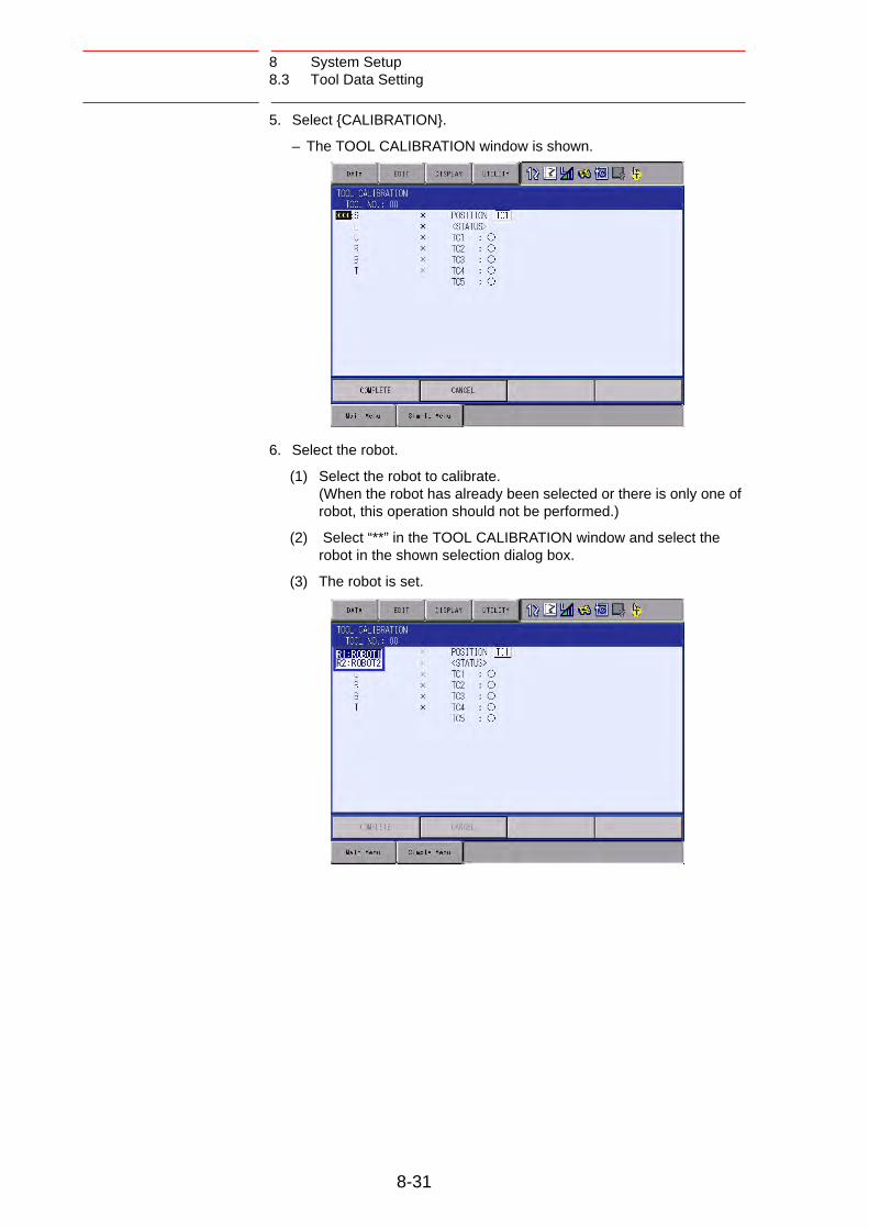
8 System Setup8.3 Tool Data Setting
5. Select {CALIBRATION}.
– The TOOL CALIBRATION window is shown.
6. Select the robot.
(1) Select the robot to calibrate. (When the robot has already been selected or there is only one of robot, this operation should not be performed.)
(2) Select “**” in the TOOL CALIBRATION window and select the robot in the shown selection dialog box.
(3) The robot is set.
8-31

8 System Setup8.3 Tool Data Setting
7. Select “POSITION”.
– The selection dialog box is shown.
(1) Select the teaching point for calibration.
8. Move the manipulator using the axis key.
9. Press [MODIFY] and [ENTER].
– Taught position is registered.Repeat 7 to 9 operation to teach TC1 to TC5.“” denotes that teaching is completed and “” denotes that it is not completed.
– To check the taught positions, call up the required window among TC1 to TC5 and press [FWD]. The manipulator moves to the set position.
– If there is a difference between the current position of the manipulator and the shown position data, “TC” next to “POSITION” in the window flashes.
8-32

8 System Setup8.3 Tool Data Setting
10. Select “COMPLETE”.
– Calibration data is registered in the tool file. Once the calibration is completed, the tool coordinate window is displayed on the screen.
8-33

8 System Setup8.3 Tool Data Setting
8.3.2.4 Clearing Calibration Data
Before the calibration of a new tool, clear the robot information and calibration data.
1. Select {DATA} under the pull-down menu.
– The pull-down menu appears.
2. Select {CLEAR DATA}.
– The confirmation dialog box is shown.
8-34

8 System Setup8.3 Tool Data Setting
3. Select {YES}.
– All data is cleared.
SUPPLE-MENT
If tool angle data is required, input the data number in the tool coordinate window.Refer to chapter 8.3.1.3 “Registering Tool Angle” at page 8-24 for the operating instructions.
8-35

8 System Setup8.3 Tool Data Setting
8.3.2.5 Checking TCP
After registering the tool file, check if the TCP is correctly registered by performing a TCP fixed operation like the one shown below, in any coordinate system other than the joint.
1. Press the COORD key .
– Select any coordinate system except “ JOINT” by pressing the
COORD key .
2. Select desired tool number.
–Show the tool coordinate window of the desired tool by pressing the
page key or selecting it in the tool list window.
Tool center point
TOOL SEL
COORD
TOOL SEL
COORD
GO BACK
PAGE
8-36

8 System Setup8.3 Tool Data Setting
3. Move the R, B, or T axes using the axis key.
– By pressing the axis keys for the R, B, and T axes, change the manipulator pose without changing the TCP position. If this operation shows a large TCP error, adjust the tool data.
SUPPLE-MENT
For details on the TCP fixed operation, see “2.3.7 Motion about TCP” in FS100 OPERATOR’S MANUAL.
TCP
8-37

8 System Setup8.3 Tool Data Setting
8.3.3 Automatic Measurement of Tool Load and Center of Gravity
8.3.3.1 Description of Automatic Measurement of Tool Load and Center of Gravity
With this function, the user can register the load of tool and the position of the tools center of gravity.
The tool load and the position of it’s center of gravity are measured and registered in a tool file.
8.3.3.2 Measurement of Tool Load and Center of Gravity
To measure the tool load and the center of gravity, move the manipulator to its home position (with the U-, B- and R-axes horizontal to the ground) and operate the U-, B- and T-axes.
NOTEThis function can be used where the manipulator is installed level on the ground.For the conditions required for manipulator installation, refer to chapter 8.4 “ARM Control” at page 8-43.
Zero-degree installation on the ground
Home Position (with the U-, B- and R-axes horizontal to the ground)
T-axis
B-axisR-axis
U-axis
L-axis
S-axis
U-
U+
B-
B+
T-
T+
NOTE To correctly measure the tool load or the center of gravity, remove the cables or wires connected to the tool.
8-38

8 System Setup8.3 Tool Data Setting
1. Select {ROBOT} under the main menu.
2. Select {TOOL}.
– The tool list window appears.
– The tool list window is called up only when the file extension function is valid.
If the file extension function is invalid, the tool coordinate window appears.
8-39

8 System Setup8.3 Tool Data Setting
3. Select the desired tool number.
– Move the cursor to the desired number in the tool list window and press [SELECT].
– The tool coordinate window of the selected number is shown.
– In the tool coordinate window, the number can be changed by
pressing the page key or selecting {PAGE}.
– To switch the tool list window and the tool coordinate window, press {DISPLAY} {LIST} or {DISPLAY} {COORDINATE DATA}.
4. Select {UTILITY} under the menu.
GO BACK
PAGE
8-40

8 System Setup8.3 Tool Data Setting
5. Select {W.GRAV.POS MEASURE}.
– The window for the automatic measurement of the tool load and the center of gravity is shown.
6. Press the page key .
– In a system with several manipulators, use the page key to change the group to be controlled.
7. Press [FWD].
– Press [FWD] once, and the manipulator moves to the home position (horizontal to the U-, B- and R-axes).
8. Press [FWD] again.
– Press [FWD] again, and measurement starts. Keep the button pressed until measurement is completed.
The manipulator moves in the order listed below. Once measurement is completed, “” changes to “”.
Measurement of the U-axis: U-axis home position +4.5 degrees
-4.5 degrees
Measurement of the B-axis: B-axis home position +4.5 degrees
-4.5 degrees
First measurement of the T-axis: T-axis home position +4.5 degrees
-4.5 degrees
Second measurement of the T-axis: T-axis home position +60
degrees +4.5 degrees -4.5 degrees
SUPPLE-MENT
• The speed during measurement automatically changes to “Medium”.
• During the measurement, “HOME” or “U” blinks on the screen.
• During the measurement, the [FWD] button has to be kept pressed. If the button is released during the measurement or if it is released before “” changes into “”, the mea-surement is aborted and the following message appears: “Stopped measurement”
• The measurement starts again from the first home position.
GO BACK
PAGE
GO BACK
PAGE
1
2
3
4
8-41

8 System Setup8.3 Tool Data Setting
– When all the measurements are completed or when all the “” marks have changed into “”, the measured data appears on the screen.
9. Select “REGISTER”.
– The measured data is registered in the tool file, and the tool coordinate window appears.
– Select “CANCEL” to call up the tool list window without registering the measured data in the tool file.
8-42
8 System Setup8.4 ARM Control
8.4 ARM Control
8.4.1 ARM Control
ARM Control, a control system originally developed by Yaskawa, achieves an enhanced robot motion performance such as improved path accuracy or reduced cycle time.
The moment of inertia and the gravity moment etc. of each axis are calculated by the ARM control function, and FS100L controls robot motion according to the result. It is necessary to set the robot setup condition and the tool load information to request these accurately.
The robot setup condition is robot installation angle relative to ground and the weight and a center of gravity position of the load installed at each part of robot, etc.
The tool load information is weight, a center of gravity position, and moment of inertia at the center of gravity, of the tool installed at the flange.
It is necessary to set these information correctly to do a better operation control by the ARM control.
8.4.2 ARM CONTROL Window
CAUTION
• Correctly set the robot setup condition.
Make sure to avoid any mistake in setting the unit indication or specifying positive and negative values. Failure to observe this caution may lead to improper control of the manipulator, resulting in error occurrence or short life span of speed reducer.
• Confirm the operation path of robot of each job when modifying settings.
Set the robot setup condition when setting up the manipulator.
Confirm the operation path of manipulator of each job afterwards when the setting should be modified after the installation.
Modifying the settings of the ARM control may slightly change the operation path. To avoid injury or damage to machinery caused by collision between tool and positioner, make sure to check the operation path before executing a job.
8-43

8 System Setup8.4 ARM Control
8.4.2.1 Robot Setup Condition
Fulfill the following robot setup condition to enable the ARM control.
• Robot installation angle
• S-head payload
• U-arm payload
Robot installation angle
The angle of the manipulator installed relative to ground is set in ANGLE REL. TO GROUND to calculate the gravity moment which loads to each axis of the manipulator.
The robot installation angle sets how much X axis of the robot coordinates has inclined with the ground around Y axis of the robot coordinates. The direction of + in the U-axis operation from the home position posture of the manipulator becomes direction of + of the robot installation angle. Therefore, the robot installation angle for a vertical downward wall mount specification becomes -90 degrees.
<Example>
If the robot installation angle is not correctly set, the manipulator cannot be properly controlled. Therefore, make sure to set the value correctly, paying special attentions to the direction “+” or “-”.
RobotinstallationAngle
+
-
X
Z
Y
0 degrees -90 degrees +90 degrees 180 degrees
NOTE
Only rotation angle around Y axis of the robot coordinates can be set in the robot installation angle. Contact Yaskawa representative when the robot is installed to incline Y axis of the robot coordinates relative to the ground.
8-44

8 System Setup8.4 ARM Control
S-head payload
Set the weight and the center of gravity position roughly when a device is installed at the S-head.
It is not necessary to set these values when there is no installed load on the S-head.
• WEIGHT (unit: kg)The weight of the installed load is set. It is not required to set a correct value, however, it is recommended to set a value slightly larger than the actual load. (Round up the value with each fraction between 0.5 to 1 kg.)
• X (from the S-axis), Y (from the S-axis) (unit: mm)The center of gravity position of the installed load is set by the dis-tance in the direction of X and the direction of Y from the S-axis cen-ter here. It can be set with a rough value. The direction of X and Y applies to the robot coordinates. The value is set by a negative number when the position is in “-” direction.
Fig. 8-1: Load on S-Head (Top View)
S axis center
(X position, Y position)
+X
+Y
-X
-Y
8-45

8 System Setup8.4 ARM Control
U-arm payload
Set the weight and the center of gravity position roughly when a device is installed on the U-arm.
A standard value is set when shipping from the factory.
Set the weight in “0” if there is no installing equipment on the U-arm.
• WEIGHT (unit: kg)The weight of the installed load is set. It is not required to set a correct value, however, it is recommended to set a value slightly larger than the actual load. (Round up the value with each fraction between 0.5 to 1 kg.)
• X (from the U-axis), HEIGHT (from the U-axis) (unit: mm)The center of gravity position of the installing load is set here. It does not care by a rough value. X (from the U-axis) is horizontal distance from the U-axis rotation center to the center of gravity position of the load. Set negative num-ber when there is mass side in the back from the U-axis rotation cen-ter.HEIGHT (from the U-axis) is height of the vertical direction from the U-axis rotation center to the center of gravity position of the load.
Fig. 8-2: Load on U-Arm: Center of Gravity Position (Side View)
NOTE ARM CONTROL window is displayed only when the secu-rity mode is set to the management mode.
X (from U-axis)
U-axisrotationcenter
Center of gravityposition
( + )( - )
HEIGHT (from U-axis)
8-46

8 System Setup8.4 ARM Control
1. Select {ROBOT} under the main menu.
2. Select {ARM CONTROL}.
– The ARM CONTROL window appears.
3. Press the page key , or select {PAGE}.
– Select the desired control group when there are two or more group axes.
4. Select the desired item.
5. Input the value and press [ENTER].
GO BACK
PAGE
8-47

8 System Setup8.4 ARM Control
8.4.3 Setting Tool Load Information
8.4.3.1 Tool Load Information
Tool load information includes weight, a center of gravity position, and moment of inertia at the center of gravity of the tool installed at the flange. These are registered in the tool file.
CAUTION
• Set the tool load information correctly.
The speed reducer longevity might decrease or the alarm might occur when the tool load information is not set correctly.
To set the tool load information correctly, following message appears when inputting the information.
“Input correct tool information. Using robot with wrong tool information may result in premature failure of the robot.”
• Confirm the operation path of robot of each job which uses the tool file after the tool load information is changed.
Set the tool load information before teaching the job after the tool is installed.
Confirm the operation path of each job which uses the tool file when the tool load information should be modified after teaching.
Modifying the tool load information may slightly change the operation path. To avoid injury or damage to machinery caused by collision between tool and positioner, make sure to check the operation path before executing a job.
* Flange CoodinatesXF: It is a direction right above when T axis is 0 pulse position and the flange surface of the manipulator turned to the front.
YF: Y axis led by XF,ZFZF: Perpendicular direction from flange surface
XF
ZF
YF
XF’
ZF’
YF’
Center of Gravity Position( Xg, Yg, Zg )
Iy
Iz
Ix
Moment of inertia around the Center of GravityIx, Iy, Iz
Weight:W
8-48

8 System Setup8.4 ARM Control
8.4.3.2 Calculating Tool Load Information
Weight: W (Unit: kg)
The total weight of the installing tool is set.
It is not required to set a correct value, however, it is recommended to set a value slightly larger than the actual load. (Round up the value with each fraction between 0.5 to 1 kg.)
Position of center of gravity: xg, yg, zg (Unit: mm)
The position of the center of gravity of the installed tool is set as the position in the flange coordinates.
Since it is usually difficult to get a strict position of the center of gravity, it can be set with a rough value. Presume and set a position of the center of gravity roughly from outline of the tool.
Set the value when the position of the center of gravity of the installed tool is clear from specifications, etc.
Moment of inertia at the center of gravity: lx, ly, lz (Unit: kg·m2)
It is an moment of inertia of the tool at the position of the center of gravity.
The value is calculated around the each axis of the coordinates which is in parallel to the flange coordinates and which home position is the position of the center of gravity of the tool.
It is not required to set a correct value, however, it is recommended to set a value slightly larger than the actual value.
This setting is used to calculate the moment of inertia which loads to each axis of the manipulator. However, the moment of inertia at the center of gravity does not need to be set when this data is small enough for the moment of inertia calculated from weight and the position of the center of gravity.
However, the setting is required when the moment of inertia of the tool is large (as a rough guide, the tool is considered to be large when the tool size is about more than 2-times the distance between the flange and the center of gravity).
The size of the tool is not too big.Setting the moment of inertia at centerof gravity is not necessary.
The size of the tool is big.Setting the moment of inertia at centerof gravity is necessary.
8-49

8 System Setup8.4 ARM Control
Rough value of the moment of inertia at the center of gravity can be calculated by the following methods.
• Method to approximate the entire tool in hexahedron or cylinder.
• Method to calculate from each weight and center of gravity position of plural mass.
Refer to the following setting examples for details.
<Example 1>
For the example shown below, the center of gravity is set on the flange coordinates assuming that the center of gravity is positioned slightly inclined to the head from the center.
There is no need to set the moment of inertia at the center of gravity since the size of the tool is not so large.
<Setting>
ZF
XF
YF
70
100
Center of Gravity Position= (100, 0, 70)
Total Weight Approx. 6.3 [kg]
7.00 [kg]
• W : 7.000 kg
• Xg : 100.000 mm
• Yg : 0.000 mm
• Zg : 70.000 mm
• Ix : 0.000 kg •m2
• Iy : 0.000 kg •m2
• Iz : 0.000 kg •m2
SUPPLE-MENT
• The own moment of inertia calculation for hexahedron and cylinder
The own moment of inertia of hexahedron and cylinder can be calculated by the next expression when the center of gravity is at the center.
Refer to the expression when the calculation of the moment of inertia at the center of gravity.
3 r 2 + H 2
Ix = Iy = * W 12 r 2
Iz = * W 2
Ly 2 + Lz2
Ix = * W 12
Lx2 + Lz 2
Iy = * W 12
Lx2 + Ly 2
Iz = * W 12
* Unit of Length : [m]2
* Unit of Weight : [kg]
X
Y
Z
IyIz
Ix
Ly
Lx
Weight:W
Lz
H
X
Z
Iz
Ix
r
Weight: W
Iy
Y
* Unit of Ix, Iy, Iz : [kgm ]
8-50

8 System Setup8.4 ARM Control
<Example 2>
It is necessary to set the moment of inertia at the center of gravity when the entire size of the tool and workpiece is large compared to the distance from the flange to the center of gravity position.
Calculate the moment of inertia at the center of gravity roughly from the expression (refer to the forementioned supplement: “The own moment of inertia calculation for hexahedron and cylinder”), by approximating the entire tool in the shape of the hexahedron or the cylinder.
If the weight of held workpiece is greatly different, it is more effective to set tool load information on each workpiece and to switch the tool on each step according to the held workpiece. Set the tool load information in the state to hold the heaviest workpiece when using the tools without switching them.
Weight: W = 55 + 40 = 95
= approx. 100[kg]
Center of gravity: Position at flange right under 250mm almost
(Xg, Yg, Zg) = (0,0,250)
Moment of inertia at the center of gravity:
The hexahedron of 0.500 x 0.400 x 1.000[m] which encloses the
entire tool + workpiece is assumed.
By the expression to calculate the own moment of inertia of hexahedron,
Ix = (Ly2 + Lz2 / 12) * W = ((0.4002 + 1.0002) / 12) * 100 = 9.667 = approx. 10.000
Iy = (Lx2 + Lz2 / 12) * W = ((0.5002 + 0.4002) / 12) * 100 = 3.417 = approx. 3.500
Iz = (Lx2 + Ly2 / 12) * W = ((0.5002 + 1.0002) / 12) * 100 = 10.417 = approx. 10.500
<Setting>
• W : 100.000 kg
• Xg : 0.000 mm
• Yg : 0.000 mm
• Zg : 250.000 mm
• Ix : 10.000 kg.m2
• Iy : 3.500 kg.m2
• Iz : 10.500 kg.m2
250
1000
400
500
XF ZF
YF
Weight of tool:Approx. 55 kg.
Weight of workpiece:Approx. 40 kg.
8-51

8 System Setup8.4 ARM Control
SUPPLE-MENT
How to calculate “Center of gravity position” and “moment of inertia at center of grav-ity” for plural mass
The center of gravity position and the moment of inertia at the center of gravity of the entire tool can be calculated by the weight and the center of gravity position of each mass when the tool can be thought that the tool consists of two or more big mass.
1. Divide the tool into some parts as the weight and the center of gravity position can be roughly presumed. It is not necessary to divide in detail. The tool is approximated in construction of rough parts.
2. Calculate the weight and the center of gravity position of the each parts on flange coordinates. It does not care by a rough value. Calculate the own moments of inertia of the big parts. (If parts are small, it is not necessary to calculate the own moments of inertia. Refer to above-mentioned supplement: “The own moment of inertia calculation for hexahedron and cylinder” for how to calculate the own moment of inertia.)
wi : Weight of the i-th parts [kg]
(xi, yi, zi) : Center of gravity position of the i- th parts (On flange coordinates) [mm]
Icxi, Icyi, Iczi : Own moments of inertia of the i-th parts [kg*m2]
3. The center of gravity position of the entire tool is calculated by the next expression.
xg = {w1 * x1 + w2 * x2 + .... + wi * xi} / (w1 + w2 + .... + wi)
yg = {w1 * y1 + w2 * y2 + .... + wi * yi} / (w1 + w2 + .... + wi)
zg = {w1 * z1 + w2 * z2 + .... + wi * zi} / (w1 + w2 + .... + wi)
4. The moment of inertia at the center of gravity position of the entire tool is calculated by the next expression.
Ix = {w1 * ((y1 - yg)2 + (z1 - zg)2) * 10-6 + Icx1} + {w2 * ((y2 - yg)2 + (z2 - zg)2) * 10-6 + Icx2} ................... + {wi * ((yi - yg)2 + (zi - zg)2) * 10-6 + Icxi}
Iy = {w1 * ((x1 - xg)2 + (z1 - zg)2) * 10-6 + Icy1} + {w2 * ((x2 - xg)2 + (z2 - zg)2) * 10-6 + Icy2} ..................... + {wi * ((xi - xg)2 + (zi - zg)2) * 10-6 + Icyi}
Iz = {w1 * ((x1 - xg)2 + (y1 - yg)2) * 10-6 + Icz1} + {w2 * ((x2 - xg)2 + (y2 - yg)2) * 10-6 + Icz ..................... + {wi * ((xi - xg)2 + (yi - yg)2) * 10-6 + Iczi}
8-52

8 System Setup8.4 ARM Control
<Example 3>
When there are two or more big mass as shown in the figure below, perform:
1. Set the center of gravity position when the center of gravity position of the entire tool is roughly understood, and set the moment of inertia at the center of gravity calculated by approximating the entire tool in the shape of hexahedron or cylinder. (It is enough in this setting usually.); or
2. When weight in each mass and the center of gravity position are understood, the center of gravity position and the moment of inertia at the center of gravity of the entire tool can be calculated. (Refer to forementioned supplement column: “How to calculate “Center of gravity position” and “moment of inertia at the center of gravity” for plural mass”.)
This example shows the calculation with the method 2.
Weight: W = w1 + w2
= 3 + 6 = 9 = approx. 10[kg]
Center of gravity: Xg = (w1 * x1 + w2 * x2) / (w1 + w2)
= (3 * 100 + 6 * 100) / (3+6) = 100.0 [mm]
Yg = (3 * 50 + 6 * (-150)) / (3+6) = -83.333 [mm]
Zg = (3 * 40 + 6 * 70) / (3+6) = 60.0 [mm]
The moment of inertia at the center of gravity position:
Ix = {w1 * ((y1 - Yg)2 + (z1 - Zg)2) * 10-6 + Icx1}
+ {w2 * ((y2 - Yg)2 + (z2 - Zg)2) * 10-6 + Icx2}
= 3 * ((50 - (-83))2 + (40 - 60)2) * 10-6
+ 6 * (((-150) - (-83))2 + (70 - 60)2) * 10-6
= 0.082 = approx. 0.100
Iy = 3 * ((100 - 100)2 + (40 - 60)2) * 10-6
+ 6 * ((100 - 100)2 + (70 - 60)2) * 10-6
= 0.002 = approx. 0.010
YF
40
70
Part 1
Part 2
X F
Z F
(Part 1) Weight: w1 = 3 kg Center of Gravity:
x1 = 100 mmy1 = 50 mmz1 = 40 mm
(Part 2) Weight: w2 = 6 kg Center of Gravity:
x2 = 100 mmy2 = -150 mmz2 = 70 mm
YF
XF
Center of Flange
100
50 150
Part 1
Part 2
(Top View)
8-53

8 System Setup8.4 ARM Control
Iz = 3 * ((100 - 100)2 + (50 - (-83))2) * 10-6
+ 6 * ((100 - 100)2 + ((-150) - (-83))2) * 10-6
= 0.080 = approx. 0.100
* The own moment of inertia (Icxi, Icyi, Iczi) of the part is disregarded in this example, since each part is smaller than the entire tool.
<Setting>
• W : 10.000 kg
• Xg : 100.000 mm
• Yg : -83.333 mm
• Zg : 60.000 mm
• Ix : 0.100 kg.m2
• Iy : 0.010 kg.m2
• Iz : 0.100 kg.m2
8-54
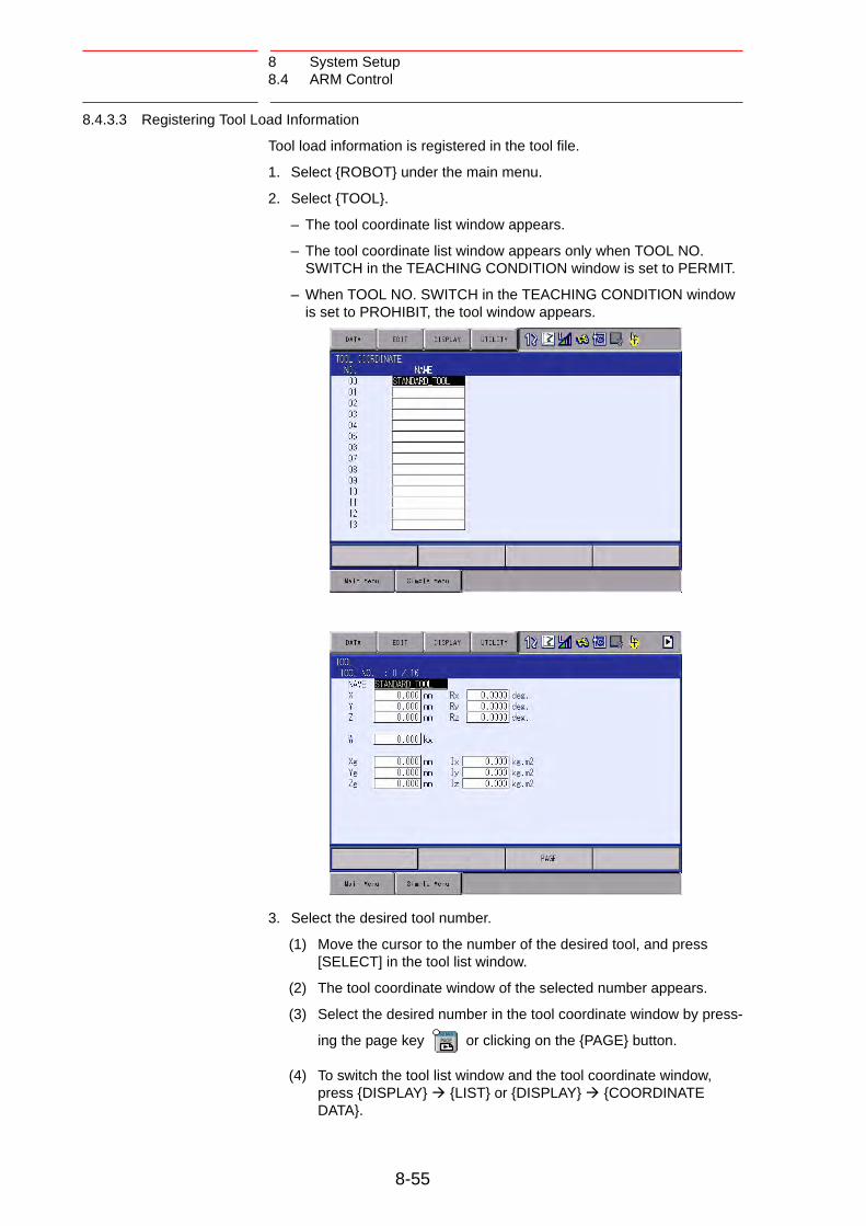
8 System Setup8.4 ARM Control
8.4.3.3 Registering Tool Load Information
Tool load information is registered in the tool file.
1. Select {ROBOT} under the main menu.
2. Select {TOOL}.
– The tool coordinate list window appears.
– The tool coordinate list window appears only when TOOL NO. SWITCH in the TEACHING CONDITION window is set to PERMIT.
– When TOOL NO. SWITCH in the TEACHING CONDITION window is set to PROHIBIT, the tool window appears.
3. Select the desired tool number.
(1) Move the cursor to the number of the desired tool, and press [SELECT] in the tool list window.
(2) The tool coordinate window of the selected number appears.
(3) Select the desired number in the tool coordinate window by press-
ing the page key or clicking on the {PAGE} button.
(4) To switch the tool list window and the tool coordinate window, press {DISPLAY} {LIST} or {DISPLAY} {COORDINATE DATA}.
GO BACK
PAGE
8-55

8 System Setup8.4 ARM Control
4. Select the desired item to register and input the value.
– The window can be scrolled with the cursor.
– The menu enters the state of a numeric input if the cursor is on the desired item to register and the [SELECT] is pressed.
5. Press [ENTER].
– The input value is registered.
– The servo power is automatically turned OFF when editing the value while the servo power is ON, followed by a message “Servo off by changing data” displayed for three seconds.
8-56
8 System Setup8.4 ARM Control
NOTE
• When the data setting is not done
It is considered that data is not set correctly in tool load information in the following cases.
• When the weight (W) is “0”.
• When the center of gravity position (Xg, Yg, Zg) are all “0”.
In these cases, the manipulator is controlled by the initial setting values (vary according to each robot model) which were set to the parameter before shipping.
Initial Setting Value:
Weight: W = Payload
Center of gravity position: (Xg, Yg, Zg) = (0, 0, Allowed value of B-axis for payload)
In this case, when an actual tool load is not large enough, the manipulator cannot sufficiently exert its function (speed and acceleration or deceleration).
Especially, when operating the manipulator with the initial setting value, a large difference in the load between the actual tool load and the initial setting value may cause vibrations in the manipulator motion. Thus, it is essential to correctly set the tool load information for the proper opera-tion of the manipulator.
Moreover, when the tool which an actual tool center of grav-ity position greatly offsets in X-direction or Y-direction is installed the generated moment by the tool cannot be com-pensated.
To set the tool load information correctly, following message appears when the playback operation is executed by using the initial setting value.
“Using robot without setting tool info. may result in prema-ture failure of the robot. Set W, Xg, Yg, and Zg in the tool file.”
• Switch of the tool file
In case that two or more tool files are used, information on an effective tool file is referred for tool load information used by the ARM control at that time in according to switch tool file.
Set the same value of tool load information in each tool file when the tool file is switched to change only TCP (when neither the weight nor the center of gravity position of the entire tool installed in the flange is changed).
Moreover, set tool load information to the corresponding tool file respectively when total weight and the center of gravity position etc. of the tool is changed (when the system which exchange the tool by automatic tool changer).
8-57

8 System Setup8.5 Work Home Position
8.5 Work Home Position
8.5.1 Description of Work Home Position
The work home position is a reference point for manipulator operations. It prevents interference with peripheral device by ensuring that the manipulator is always within a set range as a precondition for operations such as starting the line. The manipulator can be moved to the set work home position by operation from the programming pendant, or by signal input from an external device. When the manipulator is in the vicinity of the work home position, the work home position signal turns ON.
8.5.2 Setting Work Home Position
8.5.2.1 Work Home Position Window
1. Select {ROBOT} under the main menu.
2. Select {WORK HOME POS}.
– The WORK HOME POSITION window is appears.
8-58
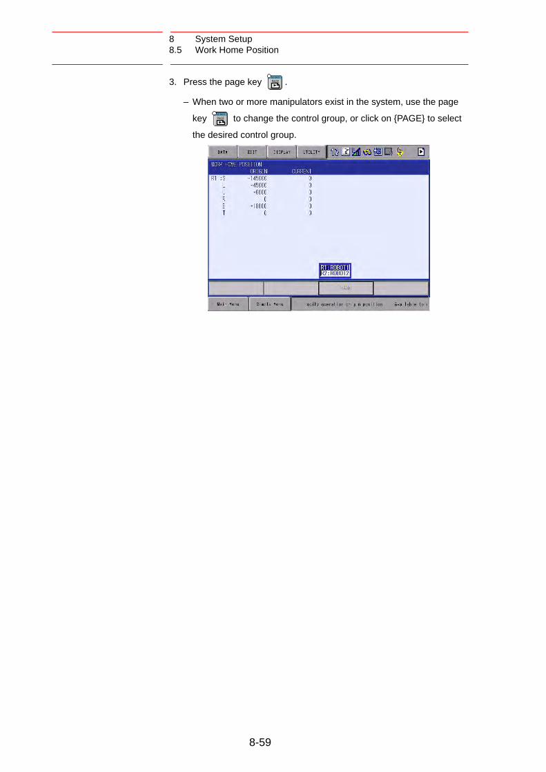
8 System Setup8.5 Work Home Position
3. Press the page key .
– When two or more manipulators exist in the system, use the page
key to change the control group, or click on {PAGE} to select
the desired control group.
GO BACK
PAGE
GO BACK
PAGE
8-59

8 System Setup8.5 Work Home Position
8.5.2.2 Registering or Changing Work Home Position
1. Press the axis keys in the work home position display.
– Move the manipulator to the new work home position.
2. Press [MODIFY], [ENTER].
– New work home position is set.
NOTE
When the work home position is changed, the cubic interfer-ence area is automatically set as cube 64 and 63 in the base coordinate system.
• The cube 64 is for ROBOT1
• The cube 63 is for ROBOT2
The work home position cube is a cube like the one shown in the figure below; the length of its sides is determined by a parameter setting made by the user (units: µm). By changing this parameter setting, the size of the cube can be changed.
Fig. 8-3: S3C1097: Length of Each Side of Work Home Position Cube (µm)
Specify whether “COMMAND POSITION” or “FEEDBACK POSITION” is to be set to the work home position cube sig-nal’s CHECK MEASURE in the interference area settings. “COMMAND POSITION” is the default setting.
P
aa
22
a2
a
8-60

8 System Setup8.5 Work Home Position
8.5.2.3 Returning to Work Home Position
In the teach mode
1. Press [FWD] in the work home position display.
– The manipulator moves to the new work home position. The moving speed is the selected manual speed.
In the play mode
When the work home position return signal is input (detected at leading edge), the TCP of the manipulator is moved to the work home position. When the manipulator moves, a message “Manipulator is moving to work home position” is displayed. In this case, the move interpolation is MOVJ, and the speed applied is the one set in the parameters. (S1CxG56; units: 0.01%.)
8.5.2.4 Outputting Work Home Position Signal
This signal is output any time the current position of the TCP of the manipulator is checked and found to be within the work home position cube.
8-61

8 System Setup8.6 Interference Area
8.6 Interference Area
8.6.1 Description of Interference Area
The interference area is a function that prevents interference between multiple manipulators or the manipulator and peripheral device.
The areas can be set up to 64 areas. There are two types of interference areas, as follows:
• Cubic Interference Area
• Axis Interference Area
The FS100L judges whether the TCP of the manipulator is inside or outside this area, and outputs this status as a signal.
8.6.2 Cubic Interference Area
8.6.2.1 Description of Cubic Interference Area
This area is a rectangular parallelepiped which is parallel to the base coordinate, robot coordinate, or user coordinate.
The FS100L judges whether the current position of the manipulator’s TCP is inside or outside this area, and outputs this status as a signal.
Cubicinterferencearea
Robot coordinateZ-axis
X-axis
User coordinatesZ-axis
Cubicinterferencearea
X-axis
Y-axisY-axis
8-62

8 System Setup8.6 Interference Area
8.6.2.2 Cube Setting Method
There are three ways to set cubic a interference area as described in the following sections:
1. Enter the maximum and minimum values for the cube coordinates.
2. Move the manipulator at the maximum and minimum value positions of the cube corner using the axis keys.
3. After entering the lengths of the three faces of the cube (axial length) using the Numeric keys, move the manipulator to the center point of the cube using the axis keys.
Minimumvalue
X-axis
Y-axis
Z-axis
Maximumvalue
Cubicinterference
area axis
Minimumvalue
X-axis
Y-axis
Z-axis
Maximumvalue
X-axis
Y-axis
Z-axis
Centerpoint
XY
Z
8-63

8 System Setup8.6 Interference Area
8.6.2.3 Setting Operation
1. Select {ROBOT} under the main menu.
2. Select {INTERFERENCE}.
– The INTERFERENCE AREA window is shown.
8-64

8 System Setup8.6 Interference Area
3. Select the desired cube number.
– Select the desired cube number with the page key or by number input.
– When selecting the cube number by number input, select {PAGE} to input the desired signal number.
4. Select “METHOD”.
– ”AXIS INTERFERENCE” and “CUBIC INTERFERENCE” are displayed alternately every time [SELECT] is pressed. If “CUBIC INTERFERENCE” is selected, the window is changed.
GO BACK
PAGE
8-65

8 System Setup8.6 Interference Area
5. Select “CONTROL GROUP”.
– A selection dialog box appears.
(1) Select the desired control group.
6. Select “REF COORDINATES”.
– A selection dialog box appears.
(1) Select the desired coordinate.
(2) If the user coordinates are selected, the number input line is dis-played. Input the user coordinate number and press [ENTER].
8-66

8 System Setup8.6 Interference Area
7. Select “CHECK MEASURE”.
– Press [SELECT] to alternate between “COMMAND POSITION” and “FEEDBACK POSITION”.
8. Select “ALARM OUTPUT”.
– Press [ENTER] to alternate between “ON” and “OFF”.
– When “ALARM OUTPUT” is “ON”, the alarm below occurs if the manipulator’s TCP enters the set interference area, and the manipulator stops its motion immediately.
AL4902: CUBE INTERFERENCE (TCP)
NOTE
To stop the manipulator movement using the interference signal (use the cube interference signal for mutual interfer-ence between robots), set CHECK MEASURE to “COM-MAND POSITION”.
When set to the “FEEDBACK POSITION”, the manipulator decelerates to a stop after entering the interference area.
When using the interference signal to inform an external unit of the actual manipulator position, use the “FEEDBACK POSITION” setting to enable the signal output in more accurate timing.
8-67

8 System Setup8.6 Interference Area
Number input of cube coordinates
1. Select “METHOD”.
(1) Press [SELECT] to alternate between “MAX/MIN” and “CENTER POS”.
(2) Select “MAX/MIN”.
2. Input number for “MAX” and “MIN” data and press [ENTER].
– The cubic interference area is set.
8-68

8 System Setup8.6 Interference Area
Teaching corners
1. Select “METHOD”.
(1) Press [SELECT] to alternate between “MAX/MIN” and “CENTER POS”.
(2) Select “MAX/MIN”.
2. Press [MODIFY].
– The message “Teach max./min. position” appears.
3. Move the cursor to “<MAX>” or “<MIN>”.
– Move the cursor to “<MAX>” when changing the maximum value, and move cursor to “<MIN>” when changing the minimum value. The cursor only moves to either “<MIN>” or “<MAX>” at this time.
4. Move the manipulator using the axis keys.
– Move the manipulator to the maximum or minimum position of the cube using the axis keys.
8-69

8 System Setup8.6 Interference Area
5. Press [ENTER].
– The cubic interference area is registered.
8-70

8 System Setup8.6 Interference Area
Number input of cube side length and teaching center
1. Select “METHOD”.
(1) Press [SELECT] to alternate between “MAX/MIN” and “CENTER POS”.
(2) Select “CENTER POS”.
2. Input data for length of the cube, then press [ENTER].
– The length is set.
8-71

8 System Setup8.6 Interference Area
3. Press [MODIFY].
– The message “Move to center point and teach” appears. The cursor only moves to either “<MIN>” or “<MAX>” at this time.
4. Move the manipulator using the axis keys.
– Move the manipulator to the center point of the cube using the axis keys.
5. Press [ENTER].
– The current position is registered as the center point of the cube.
8-72

8 System Setup8.6 Interference Area
8.6.3 Axis Interference Area
8.6.3.1 Description of Axis Interference Area
The axis interference area is a function that judges the current position of the each axis and outputs a signal. Once the maximum and minimum values have been set at the plus and minus sides of the axis to define the working range, a signal indicating whether the current position of the axis is inside or outside this range is output. (ON: inside, OFF: outside)
Fig. 8-4: Axis Interference Signal for Station Axis
0Max value+ side
Min value- side
ON
OFF
8-73

8 System Setup8.6 Interference Area
8.6.3.2 Setting Operation
1. Select {ROBOT} under the main menu.
2. Select {INTERFERENCE}.
– The INTERFERENCE AREA window appears.
3. Select the desired interference signal number.
– Select the desired interference signal number using the page key
or by number input.
– When selecting the desired interference signal number by number input, select {PAGE} to input the desired signal number.
GO BACK
PAGE
8-74

8 System Setup8.6 Interference Area
4. Select “METHOD”.
– Press [SELECT] to alternate between ”AXIS INTERFERENCE” and “CUBIC INTERFERENCE”. In this case, select “AXIS INTERFERENCE”.
5. Select “CONTROL GROUP”.
– A selection box appears. Select the desired control group.
6. Select “CHECK MEASURE”.
– Press [SELECT] to alternate between “COMMAND POSITION” and “FEEDBACK POSITION”.
8-75

8 System Setup8.6 Interference Area
7. Select “ALARM OUTPUT”.
– Press [SELECT] to alternate between “ON” and “OFF”.
– When “ALARM OUTPUT” is “ON”, the alarm below occurs if the manipulator’s TCP enters the set interference area, and the manipulator stops its motion immediately.
AL4901: AXIS INTERFERENCE
8-76

8 System Setup8.6 Interference Area
Number input of axis data coordinates
1. Select “METHOD”.
(1) Press [SELECT] to alternate between “MAX/MIN” and “CENTER POS”.
(2) Select “MAX/MIN”.
2. Input number for “MAX” and “MIN” data and press [ENTER].
– The axis interference area is set.
8-77

8 System Setup8.6 Interference Area
Teaching corners
1. Select “METHOD”.
(1) Each time [SELECT] is pressed, “MAX/MIN” and “CENTER POS” switch alternately.
(2) Select “MAX/MIN”.
2. Press [MODIFY].
– A message “Teach max./min. position” appears.
3. Move the cursor to “<MAX>” or “<MIN>”.
– Move the cursor to “<MAX>” when changing the maximum value, and move cursor to “<MIN>” when changing the minimum value. The cursor only moves to either “<MIN>” or “<MAX>” at this time.
4. Move the manipulator using the axis keys.
– Move the manipulator to the maximum or minimum position of the cube using the axis keys.
8-78

8 System Setup8.6 Interference Area
5. Press [ENTER].
– The cubic interference area is registered.
8-79

8 System Setup8.6 Interference Area
Number input of center position (WIDTH) and teaching center
1. Select “METHOD”.
(1) Press [SELECT] to alternate “MAX/MIN” and “CENTER POS”.
(2) Select “CENTER POS”.
2. Input number for “WIDTH” data and press [ENTER].
– “WIDTH” is set.
8-80

8 System Setup8.6 Interference Area
3. Press [MODIFY].
– A message “Move to the center point and teach” appears.The cursor only moves to either “<MIN>” or “<MAX>” at this time.
4. Move the manipulator using the axis keys.
– Move the manipulator to the center position of the cube using the axis keys.
5. Press [ENTER].
– The center position of the cube is registered.
8-81

8 System Setup8.6 Interference Area
8.6.4 Clearing Interference Area Data
1. Select {ROBOT} under the main menu.
2. Select {INTERFERENCE}.
– The INTERFERENCE AREA window is shown.
3. Select interference signal to be cleared.
(1) Select the desired interference signal number to be cleared using
the page key or by number input.
(2) When selecting the desired interference signal number by number input, select {PAGE} to input the desired signal number.
4. Select {DATA} under the menu.
– The pull-down menu appears.
GO BACK
PAGE
8-82

8 System Setup8.6 Interference Area
5. Select {CLEAR DATA}.
– The confirmation dialog box appears.
6. Select {YES}.
– All the data of the interference signal number are cleared.
8-83

8 System Setup8.7 Shock Detection Function
8.7 Shock Detection Function
8.7.1 Shock Detection Function
The shock detection function is a function to decrease damage due to the collision by stopping the manipulator without any external sensor when the tool or the manipulator collide with peripheral device.
When the shock is detected either in teach mode or in play mode, the manipulator is stopped immediately.
8.7.2 Shock Detection Function Setting
At the factory default setting, the threshold value is set to detect a collision without a miss even when the manipulator is operating at the maximum speed, on the assumption that the tool file is correctly set. To detect a collision during normal operation, check the following points:
• The tool’s load and moment do not exceed the rated values.
• The actual tool load and the tool file setting value are the same.
• The U-arm payload information and the set weight of U-arm payload in the ARM CONTROL window are the same.
In addition, detection sensitivity can be decreased for only a specific section where a contact task is performed.
The detection sensitivity is set by setting the detection level.
8.7.2.1 Shock Detection Level Setting
The shock detection level is set in the shock detection level set file.
The shock detection level set file are nine condition files as following figure.
• Condition numbers 1 to 7 are used when the detection level is changed in a specific section in play mode.
• Condition number 8 is used as standard in play mode: this function is operated by the detection level set in this file during playback opera-tion.
• Condition number 9 is for teach mode: the shock detection function applies the detection level set here when the manipulator is operated in teach mode.
• Condition numbers 1 to 8 are set for each axis and condition 9 is set for each group.
WARNING
• This function does not completely avoid damage to the peripheral devices; moreover, it does not guarantee the user’s safety.
• Make sure to supply the safety measures such as the safeguarding etc. Refer to chapter 1 “Safety” at page 1-1 to chapter 6 “Test of Program Operation” at page 6-1 for the safety measures in details.
Failure to observe this warning may result in Injury or damage to machinery caused by contact with the manipulator.
8-84

8 System Setup8.7 Shock Detection Function
The detection level is changed by a job instruction SHCKSET.
• After the instruction is executed, the shock will be detected by the specified detection level when the condition number is specified with the SHCKSET instruction.
• The detection level is returned to standard level when the SHCKRST instruction is executed.
SUPPLE-MENT
The detection level of condition number 8 (a standard in play mode) is adopted in play mode excluding the range between SHCKSET and SHCKRST in the job.
SUPPLE-MENT
Teach Mode Each Axis Setting Function
Usually, the detection level setting of teach mode is set for each group.
By using this function, the detection level can be set for each axis.
S2C869: Teach Mode Each Axis Setting Function
(1: VALID, 0: INVALID)
Shock DetectionLevel File
Condition number 1
Setting in the specific sectionin play mode(Condition number 1 to 7)
Standard usedfor play mode(Conditionnumber 1 to 8)
Used for teach mode(Condition number 9)
Condition number 7
Condition number 8
Condition number 9
8-85

8 System Setup8.7 Shock Detection Function
Condition Number (1 to 9)1 to 7: for changing detection level in play mode. 8: for standard detection level in play mode. 9: for detection level in teach mode.
Robot SelectSelect the manipulator whose detection level is to be changed.
Function SelectSpecifies VALID/INVALID of the shock detection function. The shock detection function is specified for each manipulator.
1. Select the manipulator whose function is to be enabled or disabled.
2. Move the cursor to “VALID” or “INVALID” and press [SELECT]. Each time [SELECT] is pressed, “INVALID” and “VALID” are displayed alternately. The change is available for all the condition numbers.
Max. Disturbance ForceIndicates the maximum disturbance force to the manipulator when the manipulator is moved in play back operation or axis operation.
Refer to this value when inputting the detection level value in .The maximum disturbance force can be cleared by selecting {DATA} {CLEAR MAX VALUE} in the menu.
Detection Level (Level range: 1 to 500)Specifies the shock detection level. Set a value larger than the maxi-mum disturbance force. The value set by default (the level 100) enables the function without false detection even if the manipulator is operated at the maximum speed.To change DETECT LEVEL, move the cursor to the subject manipula-tor, and press [SELECT] to display the numeric input status; input the value with a numeric key and press [ENTER]. To increase the detection sensitivity, set the level to small value, and to decrease the sensitivity, set the level to large value.
4
3
2
1
5
1
2
3
4
5
5
8-86

8 System Setup8.7 Shock Detection Function
Method of shock detection level file setting
1. Select {ROBOT} under the main menu.
2. Select {SHOCK SENS LEVEL}.
– The EACH AXIS LEVEL window appears.
– Perform either of the following operations to display the page of desired condition number:
(1) Press {PAGE} in the window. Enter the desired condition number using numeric keys and press [ENTER]. Then the page of the condition number appears.
(2) Press the page key to change the condition number.
3. Level setting for the condition numbers 1 to 8. Level setting values can be set for each axis on the EACH AXIS LEVEL window. Perform the following “Disturbance force measurement”, then perform “Setting all levels at once”.
Disturbance force measurement
Mount the tool, workpiece, external equipment, and equipment on the arm to the manipulator.
Set the tool file correctly. Set the load information (weight and center of gravity) of the tool.
Set the detection level values of all the axes to 100.
(1) Open the SHOCK DETECT LEVEL window.
(2) Select {DATA}, then {CLEAR MAX VALUE}.
Perform the JOB.
Setting all levels at once
Open the SHOCK DETECT LEVEL window.
Select {DATA}, then {CHANGE EVERY LEVEL}.
Enter 120 in the coefficient (%) by which the max. disturbance force is multiplied.
The following calculated value A or B, whichever is larger, is set to the DETECT LEVEL. A: (Max. disturbance force) x (coefficient = 120%) B: (Max. disturbance force) + 15
<Example> When the max. disturbance force is 80, the DETECT LEVEL is 96. When the max. disturbance force is 10, the DETECT LEVEL is 25.
GO BACK
PAGE
1
2
3
4
1
2
3
8-87

8 System Setup8.7 Shock Detection Function
4. Level setting for the condition number 9.The level setting for the condition number 9 is for the teach mode.This setting is made for each group.Refer to the max. disturbance force to set the DETECT LEVEL.
NOTE
• Perform all the jobs to use for 5 to 6 hours.
• If a work job is performed both with holding a workpiece and without holding a workpiece, measure both patterns.
• In the event of a collision while measuring the max. distur-bance force, clear the max. disturbance force by selecting {DATA}, then {CLEAR MAX VALUE}. Then try again.
• The max. disturbance force is cleared when the power is turned ON/OFF. Therefore, DO NOT set the level based on the max. disturbance force immediately after turning ON/OFF the power.
• When the teaching point, operation speed, operation posi-tion, etc. of a job are greatly changed due to teaching modification, etc., measure the max. disturbance force and set the DETECT LEVEL again.
• When the load of tool or workpiece is greatly modified, measure the max. disturbance force and set the DETECT LEVEL again.
NOTE
To avoid false detection during manipulator operation, set the following calculated value A or B, whichever is larger, to the DETECT LEVEL. An emergency stop of the manipula-tor due to the false detection may become a factor to dam-age the speed reducers and tools.
A: (Max. disturbance force) x (coefficient = 120%) B: (Max. disturbance force) + 15
<Example> When the max. disturbance force is 80, set the DETECT LEVEL to 96 or more. When the max. disturbance force is 10, set the DETECT LEVEL to 25 or more.
8-88

8 System Setup8.7 Shock Detection Function
8.7.2.2 Tool Load Information Setting
To increase the accuracy of shock detection, set the tool load information in the tool file. Refer to chapter 8.4.3 “Setting Tool Load Information” at page 8-48 for details of the tool load information setting.
8.7.2.3 U-Arm Payload Setting
To perform shock detection more accurately, set the U-arm payload.
See chapter 8.4.2 “ARM CONTROL Window” at page 8-43 for details of the U-arm payload setting.
NOTE
To adjust to the change in the grease viscosity at a cold start, the offset value is automatically added to DETECT LEVEL until the robot has operated for a certain period of time. Thus, at a cold start, the shock detection will be performed only when the value is more than or equal to the sum of DETECT LEVEL and the offset value. The offset value varies depending on the manipulator type.
NOTE DETECT LEVEL can be modified only when the security mode is set to the management mode.
8-89

8 System Setup8.7 Shock Detection Function
8.7.2.4 Instruction of Shock Detection Function
SHCKSET instruction
The SHCKSET instruction changes the shock detection level to the value set in the shock detection level file during play back operation.
The additional items of the SHCKSET instruction are as follows.
Robot SettingSpecifies the manipulator (R1, R2) or the station (ST1, ST2, ST3) of which shock detection level is to be modified. If nothing is specified, the modification is applied to the shock detection level of the job control group in this instruction. However, in the case of coordinated job, the modification is applied to the shock detection level of the slave axis group.
Shock Detection Level Condition Number (1 to 7)Specifies the shock detection level condition number in which the detection level in playback mode is set.
SHCKRST instruction
The shock detection level changed by the SHCKSET instruction is reset and returned to the detection level of the standard (value set in condition number 8) by the SHCKRST instruction.
The additional item of the SHCKRST instruction is as follows.
Robot SettingSpecifies the manipulator (R1, R2) or the station (ST1, ST2, ST3) of which shock detection level is to be reset. If nothing is specified, the modification will be applied to the shock detection level of the job control group of this instruction. However, in the case of coordinated job, the modification is applied to the shock detection level of the slave axis group.
SHCKSET R1 SSL#(1)
1
2
SHCKRST R1
1
8-90

8 System Setup8.7 Shock Detection Function
Instruction registration
The instruction is registered when the cursor is in the address area in the JOB CONTENT window in teach mode.
1. Select {JOB} under the main menu.
2. Select {JOB}.
3. Move the cursor in the address area.
SHCKSET
1. Move the cursor to the immediately preceding line where the SHCKSET instruction is to be registered.
2. Press [INFORM LIST].
– The inform list dialog box is shown.
3. Select SHCKSET instruction.
(1) SHCKSET instruction is shown in the input buffer line.
Address area Instruction
8-91

8 System Setup8.7 Shock Detection Function
4. Change the value of additional item and numerical data.
– < When registering the instruction as it is > Operate the step 5 when registering the instruction in the input buffer line as it is.
– < When adding or changing the additional item >
• When changing the shock detection level
(1) When changing the shock detection level, move the cursor to the shock detection level condition number; hold down [SHIFT] and press the up/down cursor key to change the condition number.
• When the value is input with the numeric key
I) When the value is input with the numeric key, press [SELECT] to display the input buffer line.
II) Press [ENTER] to change the number in the input buffer line.
• When robot specification is added
I) When robot specification is added, move the cursor to the instruction in the input buffer line and press [SELECT] to dis-play the DETAIL window.
II) Move the cursor to “UNUSED” of “ROBOT/STATION”, and press [SELECT].
III) The selection box appears.
8-92

8 System Setup8.7 Shock Detection Function
IV) Point the cursor to the robot to be added and press [SELECT].
V) When the addition of robot is completed, press [ENTER].
VI) The DETAIL window closes and the JOB CONTENT window appears.
5. Press [INSERT] then [ENTER].
– The instruction displayed in the input buffer line is registered.
SHCKRST
1. Move the cursor to the immediately preceding line where the SHCKRST instruction is to be registered.
2. Press [INFORM LIST].
– The inform list appears.
3. Select SHCKRST instruction.
– SHCKRST instruction appears in the input buffer line.
8-93
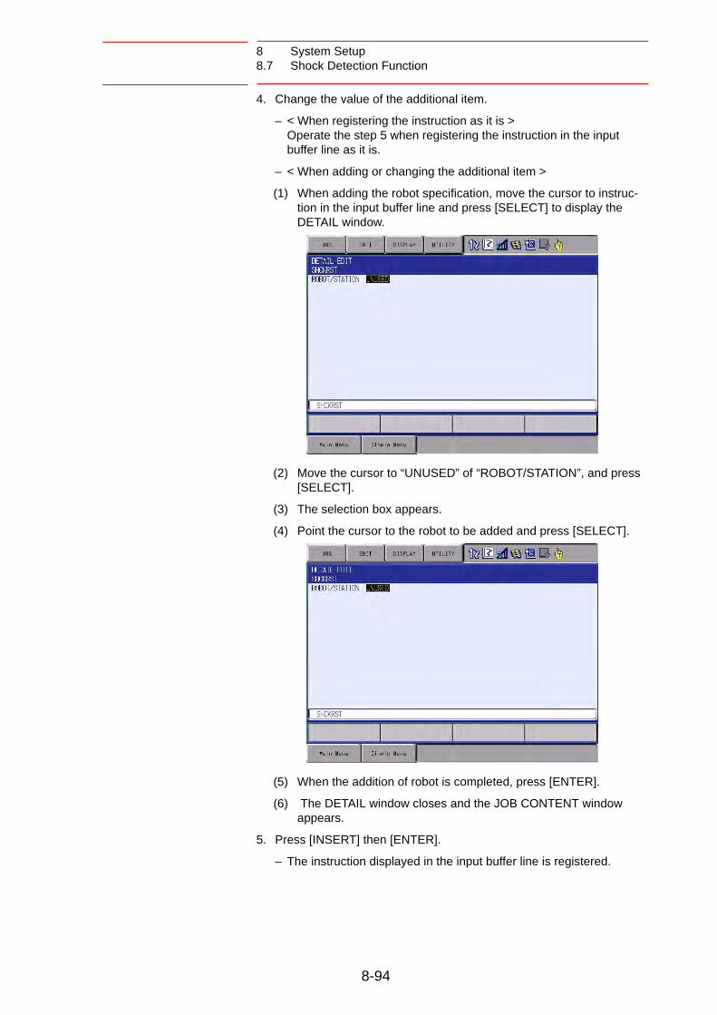
8 System Setup8.7 Shock Detection Function
4. Change the value of the additional item.
– < When registering the instruction as it is > Operate the step 5 when registering the instruction in the input buffer line as it is.
– < When adding or changing the additional item >
(1) When adding the robot specification, move the cursor to instruc-tion in the input buffer line and press [SELECT] to display the DETAIL window.
(2) Move the cursor to “UNUSED” of “ROBOT/STATION”, and press [SELECT].
(3) The selection box appears.
(4) Point the cursor to the robot to be added and press [SELECT].
(5) When the addition of robot is completed, press [ENTER].
(6) The DETAIL window closes and the JOB CONTENT window appears.
5. Press [INSERT] then [ENTER].
– The instruction displayed in the input buffer line is registered.
8-94

8 System Setup8.7 Shock Detection Function
8.7.2.5 Resetting Shock Detection Alarm
When the collision of tool/manipulator and peripheral device is detected with the shock detection function, the manipulator stops instantaneously with alarm output. In this case, the shock detection alarm is displayed.
The shock detection alarm in teach mode and play mode can be reset by the following operation.
1. Press [SELECT].
– The alarm is reset when “RESET” is selected on the alarm display, and the shock detection status is released.
2. Operation after resetting the detection status.
– In teach mode, the JOG operation of the manipulator is enabled by resetting the status.
– In the play mode, move the manipulator once to the safety position in the teach mode to check the damage though the playback operation is possible after resetting the status.
NOTE
When manipulator is stopped instantaneously while having contact with the object and the detection alarm is tried to reset on the alarm window, the situation in which the alarm cannot be reset may occur since the collision may be detected again after resetting.
In this case, set the shock detection function “INVALID”, or increase the detection level in teach mode and retreat the manipulator to a safety position.
8-95

8 System Setup8.8 User Coordinate Setting
8.8 User Coordinate Setting
8.8.1 User Coordinates
8.8.1.1 Definition of User Coordinates
User coordinates are defined by three points that have been taught to the manipulator through axis operations. These three defining points are ORG, XX, and XY, as shown in the diagram below. These three points of positional data are registered in a user coordinate file.
ORG is the home position, and XX is a point on the X-axis. XY is a point on the Y-axis side of the user coordinates that has been taught, and the directions of Y- and Z-axes are determined by point XY.
8.8.1.2 Number of User Coordinate Files
Up to 16 kinds of user coordinates can be registered. Each coordinate has a user coordinate No. and is called a user coordinate file.
NOTE It is important that the two points ORG and XX be taught accurately.
User coordinate definition point ORG: Home position XX: Point on the X-axis XY: Point on the Y-axis
ORG
X-axis
XY
XX
Z-axis
Y-axis
User coordinate file 16
User coordinate file 4User coordinate file 3
User coordinate file 2User coordinate file 1
8-96

8 System Setup8.8 User Coordinate Setting
8.8.2 User Coordinate Setting
8.8.2.1 Selecting User Coordinate File
1. Select {ROBOT} under the main menu.
2. Select {USER COORDINATE}.
(1) The USER COORDINATE window appears.
(2) The “” denotes that the user coordinates is completed to set and the “” denotes that it is not completed.
(3) To check the position of the user coordinates select {DISPLAY} {COORDINATE DATA}.
(4) The following window appears.
3. Select the user coordinate number.
8-97

8 System Setup8.8 User Coordinate Setting
8.8.2.2 Teaching User Coordinates
1. Select the robot.
– Select “**” on the upper left of the window to select the subject robot. (This operation can be omitted if the robot selection has already been made or if there is only one robot.)
2. Select “SET POS”.
– Select the teaching point.
3. Move the manipulator to the desired position with the axis keys.
8-98

8 System Setup8.8 User Coordinate Setting
4. Press [MODIFY] then [ENTER].
– Taught position is registered.
– Repeat the steps 2 to 4 to teach ORG, XX and XY.
– ““ denotes that teaching is completed and “” denotes that it is not completed.
– To check the taught positions, call up the required window among ORG to XY and press [FWD]. The manipulator moves to the set position.
– If there is a difference between the current position of the manipulator and the displayed position data, “ORG”, “XX”, or “XY” flashes.
5. Select “COMPLETE”.
– User coordinates are registered in the file.
– Once the user coordinate setting is completed, the following window appears.
8-99

8 System Setup8.8 User Coordinate Setting
8.8.2.3 Clearing User Coordinates
1. Select {DATA} under the pull-down menu.
2. Select {CLEAR DATA}.
– The confirmation dialog box appears.
3. Select {YES}.
– All data is cleared.
8-100

8 System Setup8.9 Releasing Overrun
8.9 Releasing Overrun
If the manipulator stops by overrun detection, it by the following procedure and reset the alarm and move the manipulator with the axis keys.
1. Select {ROBOT} under the main menu.
2. Select {OVERRUN}.
– The OVERRUN window appears.
CAUTION
To operate the manipulator with the overrun released, pay extra attention to the safety of the surrounding operation environment.
8-101

8 System Setup8.9 Releasing Overrun
3. Select “RELEASE”.
– The control group in which overrun is detected is indicated with “”.
– If “RELEASE” is selected, overrun is released and “CANCEL” indication will be displayed.
4. Select “ALM RST”.
– The alarm is reset and manipulator can be moved with the axis keys.
NOTEAfter releasing the overrun, if “CANCEL” is selected or the window is changed to the other one, the release of the over-run will be canceled.
8-102

8 System Setup8.10 Soft Limit Release Function
8.10 Soft Limit Release Function
The switches that are set to detect the motion range of the manipulator are called limit switches. The operating range is monitored by the software in order to stop motion before these limit switches are reached. These software limits are called “soft limits”. The operating range of the manipulator is controlled by the following two soft limits.
• Maximum motion range for each axis
• Cubic operation area set parallel to the robot coordinate system
These soft limits are continually monitored by the system, and the manipulator automatically stops when the its TCP reaches a soft limit.
When the manipulator is stopped at a soft limit, temporarily release the soft limit by the following procedure, then move the manipulator away from the soft limit in a direction opposite to the earlier operation direction.
1. Select {ROBOT} under the main menu.
2. Select {LIMIT RELEASE}.
– The LIMIT RELEASE window appears.
3. Select “SOFT LIMIT RELEASE”.
– Press [SELECT] to alternate between “VALID” and “INVALID”.
– When “SOFT LIMIT RELEASE” is set to “VALID”, the message “Soft limits have been released” appears.
– When “SOFT LIMIT RELEASE” is set to “INVALID”, the message “Softlimits off released” is displayed for a few seconds.
NOTE• The taught data cannot be registered when the soft limit is
being released.
• The setting of “SOFT LIMIT RELEASE” becomes “INVALID” when the mode is changed to the play mode.
8-103

8 System Setup8.11 All Limit Release Function
8.11 All Limit Release Function
The following limits can be released with the all limit release function:
1. Select {ROBOT} under the main menu.
2. Select {LIMIT RELEASE}.
– The LIMIT RELEASE window appears.
CAUTION
• To operate the manipulator with all limits released, pay extra attention to ensure the safety of the surrounding operation environment.
Failure to observe this caution may result in injury or damage to equipment due to the unexpected manipulator motion exceeding its range of motion.
Limit Type Contents
Mechanical Limit Limit to check manipulator’s range of motion.
L-U Interference Limit to check L- and U-axis interference area.
Soft Limit on Each Axis Soft limit to check manipulator’s range of motion.
Cube Interference Limit to check cube interference area set by user.
NOTEThe all limit release function is available only when the security mode is set to the management mode. Refer to chapter 7 “Security System” at page 7-1 for details on the security modes.
8-104

8 System Setup8.11 All Limit Release Function
3. Select “ALL LIMITS RELEASE”.
– Press [SELECT] to alternate between “VALID” and “INVALID”.
– When ALL LIMIT RELEASE is changed to “VALID”, the message “All limits have been released” is displayed. When the setting changes to “INVALID”, the message “All limits off released” is displayed for a few seconds.
8-105

8 System Setup8.12 Instruction Level Setting
8.12 Instruction Level Setting
8.12.1 Setting Contents
8.12.1.1 Instruction Set
There are three instruction sets that can be used when registering the instructions for the robot programming language (INFORM III): the subset instruction set, the standard instruction set, and the expanded instruction set.
• Subset Instruction Set: The instructions displayed in the instruction list are limited to just those that are most frequently used, reducing the number of instruc-tions that can be registered. Since few instructions are shown, selection and input are simple.
• Standard Instruction Set/Expanded Instruction Set: All the INFORM III instructions can be used. The number of addi-tional items to be used in each instruction differ in the standard instruction set and expansion instruction set. In the standard instruction set, the following functions cannot be used. However, operation becomes easier because the number of data items decreases when registering an instruction.
• Use of local variables and arrangement variable
• Use of variables for additional items (Example: MOVJ VJ = I000)
When instructions are executed, for example during playback, all the instructions can be executed regardless of the instruction set used.
Fig. 8-5: Instruction Set
Frequency usedinstructions
Expanded instruction setStandard instruction set
Subset instruction set
All instructions
Use of local variables and arrangement variablesUse of variables for additional itemsJob calls with arguments
8-106

8 System Setup8.12 Instruction Level Setting
8.12.1.2 Learning Function
When an instruction is entered from the instruction list, the additional items that were entered last time are also shown. This function can simplify instruction input.
To register the same additional items as those in the former operation, register them without changing.
1. Register an instruction.
2. The next time an attempt is made to register the same instruction as in 1, the same additional items as were registered last time are also shown in the input buffer line.
8-107
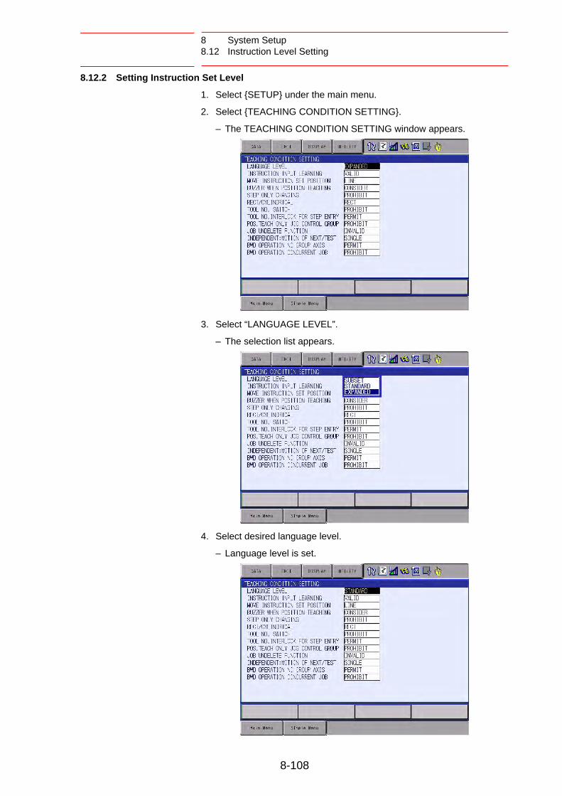
8 System Setup8.12 Instruction Level Setting
8.12.2 Setting Instruction Set Level
1. Select {SETUP} under the main menu.
2. Select {TEACHING CONDITION SETTING}.
– The TEACHING CONDITION SETTING window appears.
3. Select “LANGUAGE LEVEL”.
– The selection list appears.
4. Select desired language level.
– Language level is set.
8-108

8 System Setup8.12 Instruction Level Setting
8.12.3 Setting Learning Function
The learning function is set at “VALID” by default.
1. Select {SETUP} under the main menu.
2. Select {TEACHING CONDITION SETTING}.
– The TEACHING CONDITION SETTING window appears.
3. Select “INSTRUCTION INPUT LEARNING”.
– Press [SELECT] to alternate between “VALID” and “INVALID”.
8-109

8 System Setup8.13 Setting Controller Clock
8.13 Setting Controller Clock
To check the current date and time, follow the procedure below.
1. Select {SETUP} under the main menu.
2. Select {DATE/TIME}.
– The DATE/TIME SET window appears.
To set the current date and time, follow the procedure below.
1. While pressing the main menu key , turn the power OFF then back ON.
2. Select {SYSTEM}, then {SETUP}. Then, select “DATE” or “TIME”.
– The DATE/TIME SET window appears.
3. Select “DATE” or “TIME”.
– The input buffer line appears.
4. Input the new date/time.
– For instance, to set the date to September 1, 2010, input “2010.9.1”. To set the time at twelve o’clock, enter “12.00”.
5. Press [ENTER].
– The date or time is changed.
MAINMENU
8-110

8 System Setup8.14 Setting Play Speed
8.14 Setting Play Speed
1. Select {SETUP} under the main menu.
2. Select {SET SPEED}.
– The SPEED SET window is shown.
3. Press the page key .
– When two or more manipulators and stations exist in the system,
use the page key to change the control group, or click on
{PAGE} to select the desired control group.
GO BACK
PAGE
GO BACK
PAGE
8-111

8 System Setup8.14 Setting Play Speed
4. Select “JOINT” or “LNR/CIR”.
– The type of speed alternately changes from “JOINT” to “LNR/CIR”.
5. Select the speed to modify.
– The input buffer line appears.
6. Input the speed value.
7. Press [ENTER].
– The speed is modified.
8-112

8 System Setup8.15 Numeric Key Customize Function
8.15 Numeric Key Customize Function
8.15.1 Description of Numeric Key Customize Function
With this function, the user can set the function of an application that has been allocated to the numeric keys of the programming pendant to the other function.
Since any frequently used operation can be allocated to the numeric keys on the programming pendant, decreased key operations reduce the teaching time.
8.15.2 Allocatable Functions
There are two allocation methods as follows:
• Key Allocation (EACH)
• Key Allocation (SIM)
8.15.2.1 Key Allocation (EACH)
With key allocation (EACH), the manipulator operates according to the allocated function when the numeric key is pressed. The allocatable functions are listed below.
NOTE The Numeric Key Customize Function is allowed to set only when the security mode is set to the management mode.
Function Description
Manufacturer allocation
Allocated by Yaskawa. Allocating another function invalidates the function allocated by the manufacturer.
Instruction allocation
Allocates any instructions assigned by the user.
Job call allocation Allocates job call instructions (CALL instructions). The jobs to be called are only those registered in the reserved job names. (Specified by the registration No.)
Display allocation Allocates any displays assigned by the user.
8-113

8 System Setup8.15 Numeric Key Customize Function
8.15.2.2 Key Allocation (SIM)
With key allocation (SIM), the manipulator operates according to the
allocated function when the interlock key and the numeric key are pressed at the same time. The allocatable functions are listed below.
Function Description
Alternate output allocation
Turns ON/OFF the specified user output signal when the
interlock key and the allocated Numeric key are
pressed at the same time.
Momentary output allocation
Turns ON the specified user output signal user when the
interlock key and the allocated user key are pressed
at the same time.
Pulse output allocation
Turns ON the specified user output signal only for the
specified period when the interlock key and the
allocated Numeric key are pressed at the same time.
Group output allocation (4-bit/8-bit)
Sends the specified output to the specified general group
output signals when the interlock key and the
allocated Numeric key are pressed at the same time.
Analog output allocation
Sends the specified voltage to the specified output port
when the interlock key and the allocated Numeric key
are pressed at the same time.
Analog incremental output allocation
Sends the voltage increased by the specified value to the
specified output port when the interlock key and the
allocated Numeric key are pressed at the same time.
SUPPLE-MENT
In a system for multiple applications, a numeric key can be allocated for each application.
INTERLOCK
INTERLOCK
INTERLOCK
INTERLOCK
INTERLOCK
INTERLOCK
INTERLOCK
8-114
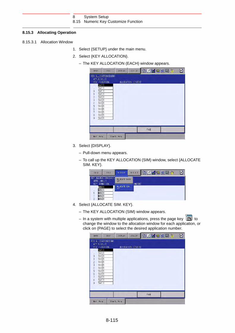
8 System Setup8.15 Numeric Key Customize Function
8.15.3 Allocating Operation
8.15.3.1 Allocation Window
1. Select {SETUP} under the main menu.
2. Select {KEY ALLOCATION}.
– The KEY ALLOCATION (EACH) window appears.
3. Select {DISPLAY}.
– Pull-down menu appears.
– To call up the KEY ALLOCATION (SIM) window, select {ALLOCATE SIM. KEY}.
4. Select {ALLOCATE SIM. KEY}.
– The KEY ALLOCATION (SIM) window appears.
– In a system with multiple applications, press the page key to change the window to the allocation window for each application, or click on {PAGE} to select the desired application number.
GO BACK
PAGE
8-115

8 System Setup8.15 Numeric Key Customize Function
8.15.3.2 Instruction Allocation
Set this function in the KEY ALLOCATION (EACH) window.
1. Move the cursor to “FUNCTION” of the key to be allocated and press [SELECT].
– Selection list appears.
2. Select “INSTRUCTION”.
– The instruction is shown in the “ALLOCATION CONTENT”.
(1) To change the instruction, move the cursor to the instruction and press [SELECT]. Then the instruction group list appears.
8-116

8 System Setup8.15 Numeric Key Customize Function
(2) Select the group which contains the instruction to modify.
(3) When the instruction list dialog box is shown, select the instruction to be changed.
8-117

8 System Setup8.15 Numeric Key Customize Function
8.15.3.3 Job Call Allocation
Set this function in the KEY ALLOCATION (EACH) window.
1. Move the cursor to the “FUNCTION” of the key to be allocated and press [SELECT].
– A selection list appears.
2. Select “JOB CALL”.
– The reserved job registration No. is shown in the “ALLOCATION CONTENT” (reserved job registration No.: 1 to 10).
(1) To change the reserved job registration No. move the cursor to the No. and press [SELECT]. Then input buffer line appears.
(2) Input the number to be changed, and press [ENTER].
8-118

8 System Setup8.15 Numeric Key Customize Function
8.15.3.4 Display Allocation
Set this function in the KEY ALLOCATION (EACH) window.
1. Move the cursor to the “FUNCTION” of the key to be allocated and press [SELECT].
– Selection list appears.
2. Select [DISPLAY].
3. Move the cursor to “ALLOCATION CONTENT” and press [SELECT].
– Character input is available.
4. Input the name of the reserved window and press [ENTER].
– The reserved name input to the “ALLOCATION CONTENT” is shown.
5. Open the window for allocation.
6. Press the interlock key and the allocated key at the same time.
– A message “Reserved display registered” appears, and the window is registered.
– In this case, the CURRENT POSITION window is registered by
pressing the interlock key + [0] with the CURRENT POSITION window displayed on the screen.
INTERLOCK
INTERLOCK
8-119

8 System Setup8.15 Numeric Key Customize Function
8.15.3.5 Alternate Output Allocation
Set this function in the KEY ALLOCATION (SIM) window.
1. Move the cursor to the “FUNCTION” of the key to be allocated and press [SELECT].
– Selection list appears.
2. Select “ALTERNATE OUTPUT”.
– The output No. is displayed in the “ALLOCATION CONTENT”.
(1) To change the output No., move the cursor to the No. and press [SELECT]. Then numeric value can be entered.
(2) Input the number to be changed, and press [ENTER].
8-120

8 System Setup8.15 Numeric Key Customize Function
8.15.3.6 Momentary Output Allocation
Set this function in the KEY ALLOCATION (SIM) window.
1. Move the cursor to the “FUNCTION” of the key to be allocated and press [SELECT].
– A selection list appears.
2. Select “MOMENTARY OUTPUT”.
– The output No. is displayed in the “ALLOCATION CONTENT”.
(1) To change the output No., move the cursor to the No. and press [SELECT]. Then numeric value can be entered.
(2) Input the number to be changed, and press [ENTER].
8-121

8 System Setup8.15 Numeric Key Customize Function
8.15.3.7 Pulse Output Allocation
Set this function in the KEY ALLOCATION (SIM) window.
1. Move the cursor to the “FUNCTION” of the key to be allocated and press [SELECT].
– A selection list appears.
2. Select “PULSE OUTPUT”.
– The output No. and output time are displayed in the “ALLOCATION CONTENT”.
(1) To change the output No. or output time, move the cursor to the No. or time and press [SELECT]. Then numeric value can be entered.
(2) Input the number or time to be changed, and press [ENTER].
8-122

8 System Setup8.15 Numeric Key Customize Function
8.15.3.8 Group (4-bit/8-bit) Output Allocation
Set this function in the KEY ALLOCATION (SIM) window.
1. Move the cursor to the “FUNCTION” of the key to be allocated and press [SELECT].
– A selection list appears.
2. Select “4 BIT OUTPUT” or “8 BIT OUTPUT”.
– The output No. and output value are displayed in the “ALLOCATION CONTENT”.
(1) To change the output No. or output value, move the cursor to the No. or value and press [SELECT]. Then numeric value can be entered.
(2) Input the number or value to be changed, and press [ENTER].
8-123

8 System Setup8.15 Numeric Key Customize Function
8.15.3.9 Analog Output Allocation
Set this function in the KEY ALLOCATION (SIM) window.
1. Move the cursor to the “FUNCTION” of the key to be allocated and press [SELECT].
– A selection list appears.
2. Select “ANALOG OUTPUT”.
– The output port number and the output voltage value are displayed in the “ALLOCATION CONTENT”.
(1) To change the output port No. or output voltage value, move the cursor to the No. or voltage value and press [SELECT]. Then numeric value can be entered.
(2) Input the number or voltage value to be changed, and press [ENTER].
8-124

8 System Setup8.15 Numeric Key Customize Function
8.15.3.10 Analog Incremental Output Allocation
Set this function in the KEY ALLOCATION (SIM) window.
1. Move the cursor to the “FUNCTION” of the key to be allocated and press [SELECT].
– A selection list appears.
2. Select “ANALOG INC OUTPUT”.
– The output port No. and incremental value are displayed in the “ALLOCATION CONTENT”.
(1) To change the output port No. or incremental value, move the cur-sor to the No. or incremental value and press [SELECT]. Then numeric values can be entered.
(2) Input the number or incremental value to be changed, and press [ENTER].
8-125

8 System Setup8.15 Numeric Key Customize Function
8.15.4 Allocation of I/O Control Instructions
In key allocation (SIM), output control instructions can be allocated to the numeric keys that have been allocated one of the following I/O controls with key allocation (EACH).
1. Allocation of I/O control instruction.
– Allocate the I/O control instruction with key allocation (SIM) following the forementioned procedure.
2. Move the cursor to the “FUNCTION” of the key that has been allocated with I/O control with key allocation (SIM) and press [SELECT].
– Selection list appears.
Function Output Control Instruction allowed to be Allocated
Alternate output allocation DOUT OT# (No.) ON
Momentary output allocation
Pulse output allocation PULSE OT# (No.) T = output time
Group output allocation (4-bit) DOUT OGH (No.) output value
Group output allocation (8-bit) DOUT OG# (No.) output value
Analog output allocation AOUT AO# (No.) output voltage value
8-126

8 System Setup8.15 Numeric Key Customize Function
3. Select “OUTPUT CONTROL INST”.
– The instruction corresponding to the I/O control allocated by key allocation (SIM) is displayed in the “ALLOCATION CONTENT”.
– The allocated instruction changes automatically when “ALLOCATION CONTENT” is changed by key allocation (SIM). Even if the I/O control allocation is changed to the default setting allocated by the manufacturer with key allocation (SIM), the settings for key allocation (EACH) remain the same.
8-127

8 System Setup8.15 Numeric Key Customize Function
8.15.5 Execution of Allocation
8.15.5.1 Executing Instruction/Output Control Allocation
1. Press the key allocated for instruction allocation or output control allocation.
– The allocated instruction is displayed in the input buffer line.
2. Press [INSERT] and [ENTER].
– The instruction displayed in the input buffer line is registered.
8.15.5.2 Executing Job Call Allocation
1. Press the key allocated for the job call allocation.
– The CALL instruction is displayed in the input buffer line.
2. Press [INSERT] then [ENTER].
– The CALL instruction shown in the input buffer line is registered.
8.15.5.3 Executing Display Allocation
1. Press the key allocated for the display allocation.
– The allocated display appears.
8.15.5.4 Executing I/O Control Allocation
Alternate output allocation, momentary output allocation, pulse output allocation, group output allocation (4-bit/8-bit), analog output allocation, analog incremental output allocation are executed by the following operation.
1. Press the interlock key and the key allocated for I/O control allocation at the same time.
– Allocated functions are executed.
INTERLOCK
8-128

8 System Setup8.16 Changing Output Status
8.16 Changing Output Status
The status of external output signals can be changed from the programming pendant by using either of the following two methods.
• On the user output status window
• On the RELAY ON window
The method that uses the RELAY ON window, which is described here, simplifies the operation for changing the status of signals that are used frequently.
1. Select {IN/OUT} under the main menu.
2. Select {RELAY ON}.
– The RELAY ON window appears.
3. Select the desired signal to change the output status.
– Select the status ( or ) of the desired signal.
NOTE
A maximum of 64 output signals can be shown on the RELAY ON window and they must be set in advance to parameters S4C327 to S4C390.
If they are not set, the sub menu in the RELAY ON window will not be displayed.
8-129

8 System Setup8.16 Changing Output Status
4. Press the interlock key +[SELECT].
– The output status is changed. (: status ON; : status OFF.)
SUPPLE-MENT
It is also possible to turn the relevant external output signal
on only for the duration that the interlock key + [SELECT] are pressed.
This selection is made in advance by setting the parameters (S4C391 to 454) to “1”.
INTERLOCK
INTERLOCK
8-130

8 System Setup8.17 Changing Parameter Setting
8.17 Changing Parameter Setting
The parameter settings can be changed only by the operator who has the correct user ID number for the management mode.
1. Select {PARAMETER} under the main menu.
2. Select the parameter type.
– The PARAMETER window appears. Select the desired parameter.
3. Move the cursor to the desired parameter number.
8-131

8 System Setup8.17 Changing Parameter Setting
– When the desired parameter number is not in the current window, move the cursor in the following way:
(1) Move the cursor to a parameter number and press [SELECT].
(2) Enter the desired parameter number with the numeric keys.
(3) Press [ENTER].
(4) The cursor moves to the selected parameter number.
8-132

8 System Setup8.17 Changing Parameter Setting
Set the parameters in the following manner.
1. Select the parameter data to be set.
(1) Move the cursor to the parameter number data (decimal or binary) in the PARAMETER window, and press [SELECT].
(2) To enter a decimal setting, select the decimal figure.
(3) To enter a binary setting, select the binary figure.
2. Enter the value.
– If a decimal figure is selected, enter a decimal value with the numeric keys.
– If a binary figure is selected, move the cursor to the binary figure data in the input buffer line, and press [SELECT].
– Each time [SELECT] is pressed, “0” and “1” alternate in the window.
– “0” or “1” can also be entered with the numeric keys.
3. Press [ENTER].
– The new setting appears in the position where the cursor is located.
8-133

8 System Setup8.18 File Initialization
8.18 File Initialization
8.18.1 Initializing Job File
1. While pressing the main menu key , turn the power OFF then back ON.
2. Change the security mode to the management mode.
3. Select {FILE} under the main menu.
4. Select {INITIALIZE}.
– The INITIALIZE window appears.
5. Select {JOB}.
– A confirmation dialog box appears.
6. Select {YES}.
– The job data is initialized.
NOTE
When JOB is initialized, the following files are reset at the same time. Be careful when initializing JOB.
• User coordinates• Variable data• System definition parameter (S4D)• Robot calibration data• Conveyor calibration data
MAINMENU
8-134

8 System Setup8.18 File Initialization
8.18.2 Initializing Data File
1. While pressing the main menu key , turn the power OFF then back ON.
2. Change the security mode to the management mode.
3. Select {FILE} under the main menu.
4. Select {INITIALIZE}.
5. Select {FILE/GENERAL DATA}.
– The INITIALIZE window appears.
6. Select the data file to be initialized.
– The selected data file/general data are marked with “”.
– The parameters marked with “” cannot be selected.
MAINMENU
8-135

8 System Setup8.18 File Initialization
7. Press [ENTER].
– A confirmation dialog box appears.
8. Select {YES}.
– The selected data file/general data are initialized.
8-136

8 System Setup8.18 File Initialization
8.18.3 Initializing Parameter File
1. While pressing the main menu key , turn the power OFF then back ON.
2. Change the security mode to the management mode.
3. Select {FILE} under the main menu.
4. Select {INITIALIZE}.
5. Select {PARAMETER}.
– The parameter selection window appears.
6. Select the parameter to be initialized.
– The selected parameter is marked with “”.
– The parameters marked with “” cannot be selected.
MAINMENU
8-137

8 System Setup8.18 File Initialization
7. Press [ENTER].
– A confirmation dialog box appears.
8. Select {YES}.
– The selected parameter is initialized.
8-138

8 System Setup8.18 File Initialization
8.18.4 Initializing I/O Data
1. While pressing the main menu key , turn the power OFF then back ON.
2. Change the security mode to the management mode.
3. Select {FILE} under the main menu.
4. Select {INITIALIZE}.
5. Select {I/O DATA}.
– The I/O data selection window appears.
6. Select data to be initialized.
– The selected data is marked with “”.
– The I/O data marked with “” cannot be selected.
MAINMENU
8-139

8 System Setup8.18 File Initialization
7. Press [ENTER].
– A confirmation dialog box appears.
8. Select {YES}.
– The selected data is initialized.
8-140

8 System Setup8.18 File Initialization
8.18.5 Initializing System Data
1. While pressing the main menu key , turn the power OFF then back ON.
2. Change the security mode to the management mode.
3. Select {FILE} under the main menu.
4. Select {INITIALIZE}.
5. Select {SYSTEM DATA}.
– The system data selection window appears.
6. Select the parameter to be initialized.
– The selected data is marked with “”.
– The system data marked with “” cannot be selected.
MAINMENU
8-141

8 System Setup8.18 File Initialization
7. Press [ENTER].
– A confirmation dialog box appears.
8. Select {YES}.
– The selected data is initialized.
8-142

8 System Setup8.19 Display Setting Function
8.19 Display Setting Function
8.19.1 Font Size Setting
FS100L enables changing the font size displayed on the screen.
The fonts displayed on the screen can be selected from eight patterns of fonts in the font size setting dialog box.
8.19.1.1 Applicable Range for Font Size Change
Changing the font size is allowed in the general display area indicated in the following figure:
8.19.1.2 Settable Font Size
The following eight patterns of fonts are available in setting the size of fonts displayed on the screen.
Generaldisplay area
Font Size Font Style
1 Small Regular
2 Small Bold
3 Regular Regular
4 Regular Bold
5 Large Regular
6 Large Bold
7 Extra large Regular
8 Extra large Bold
8-143

8 System Setup8.19 Display Setting Function
8.19.1.3 Setting Font Size
To set the font size, first off display the font size setting dialog box as follows.
1. Select {DISPLAY SETUP} then {CHANGE FONT} under the main menu.
2. The font size setting dialog box appears on the center of the current window.
8-144

8 System Setup8.19 Display Setting Function
To set the font size in the font size setting dialog box, follow the procedure below.
1. Specify the font style.
– The {Bold Type} check box can be checked or unchecked alternately each time the check box is selected.
• Check the {Bold Type} check box as follows to set the font to the bold style.
• Clear the {Bold Type} check box as follows to set the font to the reg-ular style.
8-145

8 System Setup8.19 Display Setting Function
2. Specify the font size.
– Select a button from the four buttons in the dialog box.
3. The font size setting dialog box is closed, and the screen displays the font specified in the dialog box.
To cancel the setting of the font size, follow the procedure below.
1. Select {Cancel} in the font size setting dialog box.
8-146

8 System Setup8.19 Display Setting Function
2. The dialog box closes without changing the font size.
SUPPLE-MENT
When the general display area is in the multi-window mode, the font size for each window can be set by using the font size setting dialog box. To change the font size, select one of the windows and set the font size.
NOTEDo not turn OFF the FS100L power supply when the font size is being changed (when the font size setting dialog box is on the screen).
8-147

8 System Setup8.19 Display Setting Function
8.19.2 Operation Button Size Setting
FS100L enables changing the size of operation buttons.
The button size in the main menu area, menu area, and instruction list can be respectively selected from three sizes.
8.19.2.1 Applicable Range for Button Size Change
Changing the button size is allowed in the main menu, menu (pull-down menu), and instruction list indicated in the following figure:
8.19.2.2 Settable Button Size
The following three sizes of buttons are available in setting the size of each operation button; the font style of the character string on buttons can also be specified.
Menu area (pull-down menu)
Main menuarea
Instructionlist
Button Size Font Style
1 Small Regular
Bold
2 Regular Regular
Bold
3 Large Regular
Bold
8-148

8 System Setup8.19 Display Setting Function
8.19.2.3 Setting Button Size
To set the button size, first off display the button size setting dialog box as follows.
1. Select {DISPLAY SETUP} then {CHANGE BUTTON} under the main menu.
– The font size setting dialog box appears on the center of the current window.
8-149

8 System Setup8.19 Display Setting Function
To set the button size in the button size setting dialog box, follow the procedure below.
1. Specify the area to set the button size.
(1) Select the desired area from the area setting buttons.
(2) The buttons in the selected area is subject to size setting.
(3) Note that only the last-selected button determines the area subject to size setting, even if settings are performed several times before then.
2. Specify the font style.
– The {Bold Type} check box can be checked or unchecked alternately each time the check box is selected.
• Check the {Bold Type} check box as follows to set the font to the bold style.
8-150

8 System Setup8.19 Display Setting Function
• Clear the {Bold Type} check box as follows to set the font to the reg-ular style.
3. Specify the button size.
– Select a button from the three buttons in the dialog box.
4. The font size setting dialog box is closed, and the screen displays the buttons specified in the dialog box.
– The modification is applied only to the buttons in the area selected with the area setting button. (In this example, the change is applied only to the pull-down menu buttons in the menu area.)
8-151

8 System Setup8.19 Display Setting Function
To cancel the setting of the button size, follow the procedure below.
1. Select {Cancel} in the button size setting dialog box.
– The dialog box closes without changing the button size.
NOTEDo not turn OFF the FS100L power supply when the button size is being changed (when the button size setting dialog box is on the screen, or when an hourglass is indicated in the middle of the screen).
8-152

8 System Setup8.19 Display Setting Function
8.19.3 Initialization of Screen Layout
The font/button size changed with the font/button size setting function can be collectively changed back to the regular size.
8.19.3.1 Initializing Screen Layout
To initialize the screen layout, follow the procedure below.
1. Select {DISPLAY SETUP} then {INITIALIZE LAYOUT} under the main menu.
– A confirmation dialog box appears on the center of the current window.
8-153

8 System Setup8.19 Display Setting Function
To initialize the screen layout, follow the procedure below.
1. select {OK}.
– The dialog box is closed, and the font/button sizes are collectively changed to the regular size.
8-154

8 System Setup8.19 Display Setting Function
To cancel the initialized screen layout, follow the procedure below.
1. Select {CANCEL}.
– The dialog box closes without changing the current screen layout.
8.19.4 Saving Layout
The settings of the font size and button size are saved. The screen is displayed with the font size and button size specified last time by the current controller.
NOTEDo not turn OFF the FS100L power supply when the screen layout is being initialized (when the confirmation dialog box is on the screen, or when an hourglass is indicated in the middle of the screen).
NOTEIn the maintenance mode, the screen is displayed with the standard font size and button size regardless of the settings of them. The font size and button size can be changed in the maintenance mode, but the settings are not saved.
8-155

8 System Setup8.20 Hand Vibration Control Function
8.20 Hand Vibration Control Function
8.20.1 Description of Hand Vibration Control Function
With this function, vibration caused by the hand or workpiece can be reduced.
The reduction of vibration eliminates the need to improve the accuracy of and to reduce the speed of picking-up or placing motion for handling application, which reduces cycle time.
8.20.2 Supported Models
The following high-speed handling models support the hand vibration control function:
• MPK2
• MPP3
NOTEMake correct settings to make the best of the hand vibration control function.
For settings, refer to chapter 8.20.3 “Setting Hand Vibra-tion Control Function” at page 8-157.
CAUTION
• The path and cycle time of the robot changes depending on the settings of the hand vibration control function. Make sure to check operation after changing the settings.
NOTEThe hand vibration control function can be supported by the system with one manipulator.
It cannot be supported by the system with an external axis and/or station.
8-156

8 System Setup8.20 Hand Vibration Control Function
8.20.3 Setting Hand Vibration Control Function
1. Select {ROBOT} under the main menu.
2. Select {HAND VIBRATION CONTROL}.
– The HAND VIBRATION CONTROL window appears.
FUNCTIONSpecifies VALID or INVALID of the hand vibration controlfunction. Move the cursor to “VALID/INVALID”, then press [SELECT]. Press [SELECT] to alternate between VALID and INVALID.
NATURAL FREQUENCY [Hz]Specifies the natural frequency of the hand or workpiece. Move the cursor to “NATURAL FREQUENCY” and press [SELECT] to enter a numeric value. Enter a setting value by using the numeric keys, then press [ENTER].
EFFICIENCY [%] (Range: 1 to 100)Specifies the efficiency of the hand vibration control function. Move the cursor to “EFFICIENCY” and press [SELECT] to enter a numeric value. Enter a setting value by using the numeric keys, then press [ENTER].
3. Enable the function by setting “FUNCTION” to “VALID”.
4. Set the natural frequency.
– If the natural frequency of the hand or workpiece is known, set the value. If the natural frequency of the hand or workpiece is not known, set the value with which vibration is minimized when the manipulator operates. It is acceptable to set this value even if the natural frequency of the hand or workpiece is known.
1
2
3
8-157

8 System Setup8.20 Hand Vibration Control Function
5. Set the efficiency.
– Set the efficiency of the hand vibration control function. Normally, there is no need to change it from 100%. However, by changing the value, the efficiency of hand vibration control and the cycle time can be adjusted.
SUPPLE-MENT
Any object vibrates with its own frequency and with its own waveform, and the frequency is called “natural frequency”.
Natural frequency is expressed by the number of vibration repeated in one second.
With the waveform below, the natural frequency is “5 Hz”.
SUPPLE-MENT
The efficiency of hand vibration control and the cycle time are changed according to the adjustment of the efficiency as shown below.
NOTEThe settings of the hand vibration control function can be changed only when the security mode is set to the manage-ment mode.
Efficiency
Efficiency of handvibration control
Cycle time
1%
Low
Short
100%
High
Long
8-158

8 System Setup8.21 Manual Brake Release Function
8.21 Manual Brake Release Function
8.21.1 Outline
With this function, the brake of each motor of the manipulator and the external axis can be forcibly released by using the programming pendant.
Note that the following operating conditions must be met:
• Operating conditions
(1)FS100L conditionThe FS100L must be started up normally.
(2)ModeAll modes (REMOTE, PLAY, TEACH)
(3)SecurityAll security modes (Operation, Edit, Management)
(4)Others
• The servo is not turned ON.
• The emergency stop is not incoming. (programming pendant, external signal, controller (optional))
8-159

8 System Setup8.21 Manual Brake Release Function
8.21.2 Manual Brake Release Procedure
1. Select {ROBOT} under the main menu, then select the submenu {MANUAL BRAKE RELEASE}.
– The submenu {MANUAL BRAKE RELEASE} is displayed under the main menu {ROBOT}.
2. Select {YES}.
– When the manual brake release menu is selected, a warning message appears to prevent improper operation.
8-160

8 System Setup8.21 Manual Brake Release Function
– Select {YES} to display the MANUAL BRAKE RELEASE window.
– Select {NO} to display the following window.
8-161

8 System Setup8.21 Manual Brake Release Function
3. Move the cursor to the axis whose brake is to be released. Then press
the interlock key + [SELECT] while gripping the enable switch.
– The brake of the axis to which the cursor is pointing is released and the BRAKE STATUS is displayed.
BRAKE STATUS : Brake locked :Brake released
– The brake is locked with one of the following conditions:
• [SELECT] is released. (See the CAUTION box below.)
• The emergency stop button on the programming pendant, the FS100L (optional), or the external device is pressed.
• The enable switch is released, or gripped more tightly to press it fur-ther.
• The window is switched from the MANUAL BRAKE RELEASE win-dow to another.
8.21.3 Warning Message
If the manual brake release is performed under one of the following conditions, a warning message appears in the message area on the screen. In this case, note that the brake cannot be released.
• The servo is turned ON.
• The emergency stop button on the programming pendant is pressed.
• The emergency stop button on the FS100L (optional) is pressed.
• The external emergency stop signal is incoming.
CAUTION
• The brake is released by pressing the interlock key + [SELECT] while gripping the enable switch. At this time, note that the brake
remains released when only the interlock key is released.
INTERLOCK
INTERLOCK
INTERLOCK
8-162

9 System Backup9.1 System Backup with FS100L
9 System Backup
For the FS100L, the system data can be collectively backed up in advance so that the data can be immediately loaded and restored in case of an unexpected trouble such as data loss.
9.1 System Backup with FS100L
For the FS100L, four types of backup data is available: CMOS.BIN, CMOSBK.BIN, ALCMSxx.HEX, and CMOSxx.HEX.
9.1.1 Function Types of Data
9.1.1.1 CMOS.BIN
For the normal backup, use this data.
Save: Perform in the maintenance mode (the editing mode or higher.)
Load: Perform in the maintenance mode (the management mode.)
As for the load/save procedures, refer to chapter 9.2 “Backup by CMOS.BIN” at page 9-3.
Target Area: All areas of the internally stored data.
9.1.1.2 CMOSBK.BIN
This data is used in the automatic backup function.
Save: Saves with the preset conditions in the normal mode.
Load: Perform for the system restoration in the maintenance mode (the management mode.)
For details, refer to chapter 9.3 “Automatic Backup Function” at page 9-9.
Target Area: All areas of the internally stored data.
9.1.1.3 CMOSxx.HEX
This data is loaded/saved in the FD/CF menu in the normal mode.
Save: Perform in the normal mode (the editing mode or higher.)
Load: Perform in the normal mode (the management mode.)
For details, refer to “FS100 OPERATOR’S MANUAL”.
Target Area: The collected data including “Job File”, “Data File”, “Parameter File”, “System Data”, and “I/O Data” which can be individually loaded/saved in the FD/CF menu. Because the setting information of robot etc. are not included in this collected data, the system cannot be completely restored.
9.1.1.4 ALCMSxx.HEX
This data is for the manufacturer only. Users can save but cannot load this data.
9-1

9 System Backup9.1 System Backup with FS100L
9.1.2 Device
For the backup of the FS100L system, a CompactFlash card or a USB memory stick can be used. (For the automatic backup function, memory cannot be backuped to the USB memory in the programming pendant.)
The following tables show the recommended CompactFlash and USB memory.
<Recommended CompactFlash>
< Recommended USB Memory>
In order to save the batch data, 8 MBytes per file is needed in the medium.
Note that the free space for one working file is needed in addition to the free space for the stored files when using the automatic backup function.
Also, it is recommended to store the backup data in two or more media to minimize problems if the medium is damaged.
No. Manufacturer Model Remarks
1 Hagiwara Solutions Co., Ltd. MCF10P-256MS 256MB
2 Hagiwara Solutions Co., Ltd. MCF10P-512MS 512MB
3 Hagiwara Solutions Co., Ltd. MCF10P-A01GS 1GB
4 Hagiwara Solutions Co., Ltd. MCF10P-A02GS 2GB
No. Manufacturer Model Remarks
1 Hagiwara Solutions Co., Ltd. UDG4-*GBRJS * denotes the capacity: 1GB, 2GB, 4GB
NOTE
The water-proof function of the programming pendant is not effective while a USB memory stick is connected to the pro-gramming pendant. Also, if a USB memory stick is connected constantly, it may drop off.
Use a CompactFlash card instead if there is no means to maintain the water-proof function or to prevent a USB mem-ory stick from dropping off.
To use a USB memory stick, connect it to the USB device of the main CPU board.
9-2

9 System Backup9.2 Backup by CMOS.BIN
9.2 Backup by CMOS.BIN
Perform the backup by CMOS.BIN in the maintenance mode.
The chart below shows the availability of CMOS save and CMOS load in each security mode in the maintenance mode.
Security CMOS Save CMOS Load
Operation Mode Not available Not available
Editing Mode Available Not available
Management Mode Available Available
Yaskawa Mode Available Available
9-3

9 System Backup9.2 Backup by CMOS.BIN
9.2.1 CMOS.BIN Save
Follow the procedures below to save CMOS.BIN.
1. While pressing the main menu key , turn ON the FS100L power supply.
2. Insert a CompactFlash card into the CompactFlash slot on the programming pendant.
– When using USB memory instead of CompactFlash, mount a USB memory stick to the programming pendant, select {DEVICE}, then select ”USB: PENDANT”. To connect a USB memory stick to the USB device of the main CPU board, mount a USB memory stick to the USB device, select {DEVICE}, then select ”USB: CONTROLLER”.
3. Select {EX. MEMORY} under the main menu.
– The sub menu appears.
4. Select {SAVE}.
– The save display appears.
– The items marked with “” cannot be selected.
MAINMENU
9-4

9 System Backup9.2 Backup by CMOS.BIN
5. Select {CMOS}.
– The confirmation dialog box appears.
6. Select {YES}.
– Select {YES} to save the CMOS data into a CompactFlash card.
– When saving the file, if the CMOS.BIN file already exists in the CompactFlash card, the following confirmation dialog box appears.
7. Select {YES}.
– The CMOS.BIN file is overwritten in the CompactFlash card.
9-5

9 System Backup9.2 Backup by CMOS.BIN
9.2.2 CMOS.BIN Load
Follow the procedures below to load CMOS.BIN.
1. While pressing the main menu key , turn ON the FS100L power supply.
2. Change the security mode to the maintenance mode.
3. Insert a CompactFlash card into the CompactFlash slot on the programming pendant.
– When using USB memory instead of CompactFlash, mount a USB memory stick to the programming pendant, select {DEVICE}, then select ”USB: PENDANT”. To connect a USB memory stick to the USB device of the main CPU board, mount a USB memory stick to the USB device, select {DEVICE}, then select ”USB: CONTROLLER”.
4. Select {EX. MEMORY} under the main menu.
– The sub menu appears.
5. Select {LOAD}.
– The load display appears.
– The items marked with “” cannot be selected.
MAINMENU
9-6

9 System Backup9.2 Backup by CMOS.BIN
6. Select {CMOS}.
– The confirmation dialog box appears.
7. Select {YES}.
– The dialog box “Overwrite network configuration?” appears.
8. Select {YES} or {NO}.
– If {YES} is selected, the network configuration in the controller is overwritten and the contents of the loaded “CMOS.BIN” file are reflected to the CMOS in the controller.
– If {NO} is selected, the network configuration in the controller is not updated and the other data are reflected to the CMOS in the controller.
9-7

9 System Backup9.2 Backup by CMOS.BIN
CAUTION
When the “CMOS load” is performed, the current CMOS data is replaced with the CMOS data (the contents of “CMOS.BIN”) in the selected device. Therefore, before performing the load, make sure to perform the “CMOS Save” of the CMOS data to be loaded.
After the “CMOS load”, check if the contents written in the FS100L are the same as before, and check to be sure that safety is confirmed with the current manipulator position. After that, start the manipulator’s operation.
CAUTION
When the network configuration is updated, the IP address in the controller is also updated. After the update, the settings of IP address and subnet mask are changed, which may make it impossible to communicate with the programming pendant or computer. Make sure to record the network configuration of the programming pendant, computer, etc. in advance.
9-8

9 System Backup9.3 Automatic Backup Function
9.3 Automatic Backup Function
9.3.1 Automatic Backup Function
9.3.1.1 Objective
With the automatic backup function, the data saved in the FS100L such as system setting or operational condition are collectively backed up in the specified device.
In case of an unexpected trouble such as data loss, the backup data saved in the CompactFlash card by the automatic backup function can be loaded to the FS100L memory to restore the file data.
9.3.1.2 Outline
The automatic backup function saves the internally stored data in a single file in advance for the smooth restoration from unexpected troubles of the FS100L.
The teaching operation is one of the factors that changes the internally stored data. Thus, a mode which backs up the latest data after the teaching operation is prepared. To confirm the termination of the teaching operation, check the mode key whether it is changed from teach mode to play mode.
Other than the teaching operation, the present position of the robot or the value of a variable can be pointed out as the factors to change the internally stored data. These data, however, are changed after each operation and have very little need to be retained permanently. Accordingly, backing up these data at regular interval should be well enough to operate and the mode to back up the data at regular interval is also prepared.
Furthermore, the mode to back up the data when starting up the FS100L and when inputting signals are also available for some specific versions.
With the automatic backup function, all the part where the internal data is stored in the physical memory area is collectively saved. If there is any data which is in the middle of changing while executing the automatic backup function, the data might not be usable for restoration because of its inconsistency. Therefore, the function is terminated with an error during the play back operation or while the manipulator is in motion so that the automatic backup cannot be operated. Set the automatic backup function to be executed while the manipulator is not in the playback status and while the manipulator is stopped.
NOTEThe automatic backup function is enabled only while the FS100L power supply is ON whereas it isn’t while in the maintenance mode or the power supply is OFF.
9-9

9 System Backup9.3 Automatic Backup Function
The automatic backup function has the following functions and features.
No. Function/Feature Explanation
1 Cyclic backupIn the teach mode, the data in memory is backed up in a specified cycle from a specified starting time.
This function backs up as much of the latest data as possible during editing. The backup data saved in the CompactFlash card can be loaded to the FS100L in case of data loss so that the damage can be minimized.
2 Backup when switching modesWhen switching the mode from the teach mode to the play mode, the data in memory is backed up.
The editing data is backed up when editing is completed. The latest data is automatically backed up with this mode.
3 Backup when start-upWhen the FS100L starts up, the data in memory is backed up.
When the FS100L starts up, the data in memory is backed up. Since the editing/playback operation is usually completed when the FS100L power is turned OFF, the latest data is automatically backed up with this mode.
4 Backup when inputting specified signalsThe data in memory is backed up when a specified signal (#40560) is input.
The data in memory is backed up by the signal from the host at the intended timing. Although the above mentioned items 1 to 3 are designed to back up the data automatically, this function backs up the data in accordance with the instruction from the host.
5 Backup while robot program is stoppedThe backup during playback is disabled. However, in the play mode, the backup is enabled if the robot is stopped. (“Cyclic backup” and “Backup when inputting specified signals”)
Backs up the variables for essential data.
6 Backup and retry at low priorityThe data in memory is backed up at low priority so that this operation does not affect the other operations. When other operations affect the backup operation, the backup is suspended and retried later.
The backup operation hardly affects the other operations so that the programming pendant can be used even during the backup operation.
7 Backup in binaryThe data is saved as binary data. The range is same as that of the “ALL CMOS AREA” in {FD/CF}, but the data type is different.
Backup in binary allows the system to be easily and speedily restored.
8 Setting of itemsParameters can limit the settings of the backup condition.
Unnecessary settings can be avoided with this setting.
9-10

9 System Backup9.3 Automatic Backup Function
9.3.2 Settings for Automatic Backup
To set the automatic backup function, insert a CompactFlash card into the CompactFlash slot on the programming pendant or connect a USB memory stick to the USB device of the main CPU board, then set each item on the AUTO BACKUP SET display.
To use the automatic backup function, insert a CompactFlash card into the CompactFlash slot on the programming pendant or insert a USB memory stick into chapter 9.3.2.2 “USB Device of Main CPU Board” .
9.3.2.1 CompactFlash
When the data could not be saved in a CompactFlash card during an automatic backup due to the absence or insufficient capacity of the CompactFlash card, an error message “Cannot backup the media” appears. (At the same time, the signal “occurrence of error” is output, but the robot program will not stop.) Check if the CompactFlash card is inserted and if it has enough capacity, and take the necessary measures.
Yaskawa recommends that the data be saved in two or more CompactFlash cards to minimize problems if the CompactFlash card is damaged. Regarding CompactFlash card, refer to <Recommended CompactFlash> in chapter 9.1.2 “Device” at page 9-2.
Storage capacity needed for the CompactFlash card is as follows:(The number of stored files + 1) X 8 MByte
The number of storable files is automatically calculated and the MAX value is shown when AUTO BACKUP SET display appears. (Up to 100 files can be stored.)
NOTE
Four ways to perform the automatic backup are available: “Cyclic backup”, “Backup when switching modes”, “Backup when start-up”, and “Backup when inputting specified sig-nals”.
The automatic backup can be performed only when the robot is not during playback and the robot is stopped.
9-11

9 System Backup9.3 Automatic Backup Function
9.3.2.2 USB Device of Main CPU Board
When the data could not be saved in a USB memory stick during an automatic backup due to the absence or insufficient capacity of the USB memory stick, an error message “Cannot backup the media” appears. (At the same time, the signal “occurrence of error” is output, but the robot program will not stop.) Check if the USB memory stick is inserted and if it has enough capacity, and take the necessary measures.
Yaskawa recommends that the data be saved in two or more USB memory sticks to minimize problems if the USB memory stick is damaged. Regarding USB memory stick, refer to < Recommended USB Memory> in chapter 9.1.2 “Device” at page 9-2.
Storage capacity needed for the USB memory stick is as follows:(The number of stored files + 1) X 8 MByte
The number of storable files is automatically calculated and the maximum number is shown when AUTO BACKUP SET display appears. (Up to 100 files can be stored.)
9-12

9 System Backup9.3 Automatic Backup Function
9.3.2.3 AUTO BACKUP SET Display
Settings
Select the following items on the AUTO BACKUP SET display and set values for the automatic backup.
• RESERVE TIME BACKUP (VALID/INVALID of the cyclic backup)
• BASE TIME
• BACKUP CYCLE
• RETRY CYCLE
• MODE CHANGE BACKUP (VALID/INVALID of the backup when switching the mode from teach mode to play mode)
• STARTUP AUTO BACKUP (VALID/INVALID of the backup when the FS100L starts up)
• SPECIFIC INPUT BACKUP (VALID/INVALID of the backup when inputting specified signals)
• UNIV.OUT NO. ON ERROR
• DISPLAY AT EMERGENCY
• DURING ALARM OCCURENCE
• STORED FILE SETTING
• DEVICE
NOTE
• With the version in which “STORED FILE SETTING” is settable, the capacity of a CompactFlash card inserted into the programming pendant is checked when the set-ting window appears. Therefore, a few seconds may be needed to open the setting window and an error may occur if no CompactFlash card is inserted.
• When changing the settings of “STORED FILE SETTING” or executing “ARRANGE”, the files “CMOSBK.BIN” and “CMOSBK??.BIN” (? is a number) in the CompactFlash card are changed in name or deleted. If a certain file of this type is needed to be saved before changed in name or deleted, evacuate it into a PC, etc. beforehand.
NOTE Each item’s setting cannot be changed in the AUTO BACKUP SET display during alarm occurrence.
9-13

9 System Backup9.3 Automatic Backup Function
1. Turn ON the FS100L.
– If the auto backup function is already set valid, insert a CompactFlash card.
2. Insert a CompactFlash card into the CompactFlash slot on the programming pendant.
3. Change the security mode to the management mode.
4. Select {SETUP} under the main menu.
5. Select {AUTO BACKUP SET}.
– The AUTO BACKUP SET display appears.
RESERVE TIME BACKUPSets the backup function to valid or invalid in a specified cycle from a specified starting time. Press [SELECT] to alternate between “INVALID” and “VALID”.
The reserve time can be set by inputting values in , , and in the display. Every time values are set to these three items, reset the RESERVE TIME BACKUP to VALID. If these settings are incorrect, the RESERVE TIME BACKUP cannot be reset to VALID. If so, check and then change the values to the correct settings.
BASE TIMESpecifies the reference time to start reserve time backup. The time elapsed from the reference time for a BACKUP CYCLE period is recognized as the BACKUP TIME. The first automatic backup is performed at the first BACKUP TIME after the power of the FS100L is turned ON. The automatic backup after the first time, is performed at the interval of BACKUP CYCLES. The reference time ranges from 0:00 to 23:59.
BACKUP CYCLESpecifies the length of time for a cycle to back up. After the first backup, the next backup is performed automatically in the time specified in the BACKUP CYCLE. Set the backup cycle in minutes. The cycle setting ranges from 10 to 9999 minutes, and is longer than the RETRY CYCLE.
1234567891011121314
15
1
2 3 4
2
3
9-14

9 System Backup9.3 Automatic Backup Function
RETRY CYCLESpecifies the length of time for a cycle to retry backing up when the backup operation is suspended. After being suspended, the backup is retried in the time specified in the RETRY CYCLE. Set the retry cycle in minutes. The cycle setting ranges from 0 to 255, and is shorter than the BACKUP CYCLE. When it is set to 0, retry will not be performed.
MODE CHANGE BACKUPSets the automatic backup function to be valid or invalid when the mode is switched from teach mode to play mode. Press [SELECT] to alternate between “INVALID” and “VALID”.
STARTUP AUTO BACKUPSets the backup function to be valid or invalid when the power of the FS100L is turned ON. Press [SELECT] to alternate between “INVALID” and “VALID”.
SPECIFIC INPUT BACKUPSets the backup function to be valid or invalid when specific input signal (# 40560) is input (rising edge from 0 to 1). Press [SELECT] to alternate between “INVALID” and “VALID”.
UNIV.OUT NO. ON ERROROutputs “1” to the specified user output signal which was specified in this chapter when the automatic backup error occurs. The term “automatic backup error” here means that the backup is not performed successfully before the next backup (including retry opera-tion) starts.
DISPLAY AT EMERGENCYSets the method of notification of the automatic backup error to “ERROR” or “MESSAGE”. Press [SELECT] to alternate between “ERROR” and “MESSAGE”.
DURING ALARM OCCURENCESets the backup function to be valid or invalid when an alarm occurs. Press [SELECT] to alternate between “INVALID” and “VALID”.
DEVICESpecifies the device to store data. Press [SELECT] to specify the device. When the device is set to “CF: PENDANT”, the automatic backup is per-formed only if communication is established between the programming pendant and the FS100L, and one of the four settings (RESERVE TIME BACKUP, MODE CHANGE BACKUP, STARTUP AUTO BACKUP, and SPECIFIC INPUT BACKUP) in the AUTO BACKUP SET display is set to “VALID”.
STORED FILE SETTINGSets the number of files to be stored by the automatic backup function. The number mentioned on the right side of this item with “(Max)” indica-tion is the maximum number of files (up to 100) that can be stored in the CompactFlash card inserted when this window is displayed. The settings range from 1 to (Max). When this setting value is changed, the backup file arrangement starts.
4
5
6
7
8
9
10
11
12
9-15

9 System Backup9.3 Automatic Backup Function
BACKUP FILESIndicates the existence of the files or the number of backup files stored in the CompactFlash card inserted when this window is displayed.
LATEST BACKUP FILEIndicates the date of the latest file in the CompactFlash card inserted when this window is displayed.
ARRANGEWhen the setting of maximum number of stored files is changed, the file arrangement of the backup files in the CompactFlash card is executed. With this operation, the file arrangement can be performed without changing the maximum number of stored files.
6. Set the desired item, and press [ENTER].
Window setting restrictions
RS parameter can restrict the settings of some items in the automatic backup window.
When setting the bit of RS096 parameter shown below to “1”, the corresponding items are restricted. The restricted items are indicated with “INVALID” in the display and input and modification to the item become impossible. Also, the automatic backup does not function with the restricted items.
13
14
15
RESERVE TIME BACKUP
<RS096>
MODE CHANGE BACKUP
STARTUP BACKUP
RETRY CYCLE
DURING ALARM BACKUP
SPECIFIC INPUT BACKUP
D5 D4 D3 D2 D1 D0D6D7
9-16

9 System Backup9.3 Automatic Backup Function
9.3.2.4 FS100L Status and Automatic Backup
* Retry is not performed when an error occurs. * An error can be indicated by a message depending on setting.
Reserve time backup
While the data in the FS100L memory is being edited or overwritten, the automatic backup is not performed at the specified backup starting time and is suspended and retried later. To start the backup at the reserved time, set to the time when the robot program is stopped and no job or file is edited.
Backup when switching from teach mode to play mode
When the mode is switched from the teach mode to the play mode, backup starts.
This switch is ignored if executed during backup operation.
Backup when FS100L starts up
Since the automatic backup process is added to the FS100L start-up process, a few extra seconds are needed to start up the FS100L.
Backup Timing FS100L Status Automatic Backup
CompactFlash ready to save the data
Absence or insufficient capacity of the CompactFlash
From a specified starting time
Teach mode Editing (Accessing to the memory)
Retry Retry
When editing is interrupted
Backup Error
Play modeRemote mode
Executing jobs Disabled Disabled
When stopped Backup Error
When a specified signal (#40560) is input
Teach mode Editing (Accessing to the memory)
Error Error
When editing is interrupted
Backup Error
Play modeRemote mode
Executing jobs Disabled Disabled
When stopped Backup Error
When switching the mode from the teach mode to the play mode
- Backup Error
When the FS100L starts up
- Backup Error
9-17

9 System Backup9.3 Automatic Backup Function
Backup when specific signal is input
While the FS100L memory is edited such as overwriting, the backup operation becomes an error even if there is an input to a specific signal (#40560). To start the specific input backup, perform it while the robot program is stopped and a job or file is not being modified.
Also, since the signal input is executed at rising detection, turn the signal to “0” if it is already “1”, then return to “1” again.
Overwriting limit in CompactFlash
The number of times to overwrite the CompactFlash card is limited. Because frequent backup operations may shorten the life of CompactFlash card, minimize the number of backup times.
Overwriting limit in USB memory
The number of times to overwrite the USB memory stick is limited. Because frequent backup operations may shorten the life of USB memory stick, minimize the number of backup times.
9-18

9 System Backup9.3 Automatic Backup Function
9.3.2.5 Setting Examples
Setting Example 1
The following diagram shows a setting example with the following conditions:
BASE TIME: 12:30
BACKUP CYCLE: 60 (minutes)
RETRY CYCLE: 10 (minutes)
Setting Example 2
The following diagram shows a setting example with the following conditions:
BASE TIME: 20:00
BACKUP CYCLE: 1440 (minutes) (24 hours)
RETRY CYCLE: 60 (minutes)
Power ON
11:301st day
BASE TIME
12:301st day
13:301st day
BACKUP CYCLE
RETRY CYCLE
Backup Backup Backup
11:40 11:5011:001st day
Power ON
20:001st day
BASE TIME
20:002nd day
20:003rd day
BACKUP CYCLE
RETRY CYCLE
Backup
21:00 22:008:001st day
Backup Backup
NOTEWhile a job is being executed, the automatic backup or retry is not performed. Also, after an error occurs in writing into the selected device, the retry is not performed until the next backup starting time.
9-19

9 System Backup9.4 Restoring Backup Data
9.4 Restoring Backup Data
Restore the backup data saved in the CompactFlash card to the FS100L in the maintenance mode.
9.4.1 Restoring Procedure
1. Insert the CompactFlash card with the backup data into the CompactFlash slot on the programming pendant.
– The backup data is stored under the file name “CMOSBK.BIN” or “CMOSBK??.BIN” (? is a number).
2. While pressing the main menu key , turn ON the FS100L power supply.
3. Change the security mode to the management mode.
4. Select {EX. MEMORY} under the main menu.
– The sub menu appears.
5. Select {SYSTEM RESORE}.
– The SYSTEM RESTORE display appears.
6. Select {SYSTEM RESTORE}.
– The BACKUP FILE LIST display appears.
MAINMENU
9-20

9 System Backup9.4 Restoring Backup Data
7. Select the file to be loaded.
– The confirmation dialog box “Initialize monitoring time?” appears.
– Select {YES} to initialize the system monitoring time. Select {NO} to continue counting the current system’s monitoring time.
8. Select {YES} in the confirmation dialog box.
– The confirmation dialog box “Overwrite network configuration?” appears.
9-21

9 System Backup9.4 Restoring Backup Data
9. Select {YES}.
– The network configuration set in the FS100L is overwritten, and the loaded contents of “CMOS.BIN” or “CMOSBK??.BIN” (? is a number) are loaded.
– When the load of “CMOSBK.BIN” or “CMOSBK??.BIN” (? is a number) starts, the message “Loading system data. Don’t turn the power off.” appears.
CAUTION
When “SYSTEM RESTORE” is performed, the internally stored data in the FS100L is replaced with the contents of “CMOSBK.BIN” or “CMOSBK??.BIN” (? is a number). Give due consideration to it before performing “SYSTEM RESTORE”.
After “SYSTEM RESTORE”, check if the contents written in the FS100L are the same as before, and check to be sure that safety is confirmed with the current manipulator position. After that, start the manipulator’s operation.
9-22

9 System Backup9.5 Error List
9.5 Error List
9.5.1 Error Contents
Error No.
Data Message Cause
0770 * The robot or the station is in motion.
The automatic backup would not work when the robot or a manipulator is in motion.
3390 File not found The file to be loaded no longer exists.
3460 * Check storage medium
1 Insufficient capacity of the storage medium.Check the medium.
2 Cannot access to the storage medium.Check the medium.
3501 * Cannot backup to medium Cannot access to the storage medium.Check the medium.
3550 * The automatic backup is executed. Try it later.
The automatic backup window cannot be called to display while the automatic backup is being processed.
3551 * The automatic backup is executed. Arrange the file after it is finished.
The file arrangement cannot be operated during the automatic backup operation.
3560 * Failed to re-arrange the backup file.
Failed to re-arrange the backup file in the storage medium for a reason other than access.
3580 * Accessing to backup file. Try it later.
To display another window and then display the automatic backup window again after “ARRANGE” operation, “ARRANGE” process must be completely finished.
3581 * Accessing to backup file. Try “ARRANGE” operation later.
The previous “ARRANGE” process must be completely finished to perform the next “ARRANGE” operation.
9-23

9 System Backup9.6 Restoring FS100L Controller
9.6 Restoring FS100L Controller
Acquire the FS100L system program and the FS100L batch data (file name: CMOS.BIN) in advance by following the procedures below.This enables rapid and easy restoration of the system in case of system failure.
9.6.1 Data Backup and Program Upload
In the FS100L system, the system program and the backup data can be backuped by either collective operation or individual operation. When executing the backup, following devices can be used.
• FS100L : USB memory
• Programming pendant: USB memory
• Programming pendant: CompactFlash card
9.6.1.1 Backup Medium Preparation
For saving the FS100L system program, supply a CompactFlash card or a USB memory stick with free space of 50 MB or more, and follow the procedure below.
1. Connect the prepared device (CompactFlash card or USB memory stick) to the PC.
2. Delete all data in the device by using Windows Explorer, etc.
3. Remove the device from the PC, then insert it into the programming pendant or the main CPU board.
Fig. 9-1: Inserting CompactFlash Card into Programming Pendant
Make sure to insert a CompactFlash card to the correct direction. Make the programming pendant face up, and make the center notches of both sides and the tip of the CompactFlash card face down, then insert it slowly.
If the CompactFlash card is inserted forcibly, the card or the CF card slot may be damaged.
CompactFlash card slot
Top
TipNotch
Insertion direction
TEACHPLAY
REMOTESTART HOLD
X+R+
Y+B+
Z+T+
X-R-
Y-B-
Z -T -
8+8-
X+S+
Y+L+
Z+U+
X-S-
Y-L -
Z-U-
E+E-
SERVO ON
HIGHSPEED
FAST
SLOW
SELECT
TOOL OF0
1TOOL ON2
TOOL ONJOB
3
SMOV4 5 6
SYNCROSINGLE
7 8 9
TOOL OFJOB
ASSIST!?
AREA
SERVOON
READY
SHIFT
DIRECTOPEN
GO BACK
PAGEMULTI
LAYOUT
MAINMENU
ROBOT
EX.AXIS
ENTRY
SIMPLEMENU
TOOL SEL
COORD
DELETE INSERT
MODIFYMOTIONTYPE
INFORMLIST
USAGE
AUX
CANCEL
INTERLOCK TEST
START
BWD FWD
ENTER
SHIFT
MANUAL SPEED
9-24

9 System Backup9.6 Restoring FS100L Controller
After inserting the card into the slot, make sure to close the cover of the slot before use.
Fig. 9-2: Inserting USB Memory Stick into Programming Pendant
Make sure to insert a USB memory stick to the correct direction. Make the programming pendant face down, and make the top of the USB memory stick face up and make the connector point upward, then insert it slowly.
If the USB memory stick is inserted forcibly, the stick or the USB connector may be damaged.
After removing the stick from the connector, make sure to close the cover of the connector before use.
Fig. 9-3: Inserting USB Memory Stick into Main CPU Board
Make sure to insert a USB memory stick to the correct direction. Make the top of the USB memory stick face to the left, then insert it slowly.
USB connector
Top
USB memory stick
Insert part
Top
9-25

9 System Backup9.6 Restoring FS100L Controller
If the USB memory stick is inserted forcibly, the stick or the USB connector may be damaged.
After removing the stick from the connector, make sure to close the cover of the connector before use.
File system of device
Use an FAT 16 or FAT 32 formatted USB memory stick.
Precautions for handling device
• Do not subject the device to excessive force or shock by dropping it, bending it, etc.
• Do not subject it to water, oil, organic solvent, dust, or soot.
• Do not use or store it in a location where excessive static electricity or electrical noise is present.
• During data writing or reading, do not remove or insert the device and do not turn the power OFF.
• Backup the data regularly to another medium for data protection. This can minimize the impact of data damage or loss in case of improper operation or accident.
Recommended device
It is recommenced to use the CompactFlash cards or USB memory sticks listed in chapter 9.1.2 “Device” at page 9-2.
9-26

9 System Backup9.6 Restoring FS100L Controller
9.6.1.2 Backup by Batch Operation
Backup function by a batch operation is performed in the maintenance mode. Prepare a device with 50MB or more capacity for backup and follow the instructions below.
1. While pressing the main menu key , turn ON the FS100L power supply.
2. Insert a CompactFlash card into the programming pendant.
– When using a USB memory in stead of a CompactFlash card, insert the USB memory to the programming pendant, and then select {EX.DEVICE} - {DEVICE} - {USB: PENDANT}.
– When using a USB memory and attaching it to the USB device on the main CPU board, insert the USB memory to the device, and then select {EX.DEVICE} - {DEVICE} - {USB: CONROLLER}.
3. Select {EX.DEVICE} under the main menu.
– EX.DEVICE sub menu window appears.
4. Select {SAVE}.
– SAVE window appears.
MAINMENU
9-27

9 System Backup9.6 Restoring FS100L Controller
5. Select {ALL FILE + CMOS}
– A confirmation dialog box appers.
– Item marked with ”■” cannot be selected.
6. Select {YES}.
– When {YES} is slected in the dialog box, the system program and the backup data are saved in the specified device.
– Following dialog box appears in case the system program and the backup data are already saved in the specified device.
9-28

9 System Backup9.6 Restoring FS100L Controller
7. Select {YES}.
– When {YES} is selected in the dialog box, the system program and the backup data are overwritten in the specified device
– Do not turn OFF the power supply while following messages are appeared in the human interface area: “Saving system data. Don't turn the power off.” or “(File name) is being executed.” Don't turn the power off.”.Should the power is turned OFF, deleted the device data used in the PC and do the same operation again.
9-29

9 System Backup9.6 Restoring FS100L Controller
9.6.1.3 Data Backup by Individual Operation
Backup the FS100L batch data (file name: CMOS.BIN) by following the procedure below.
When using the programming pendant, perform the steps 1 to 6, and when not using the programming pendant, perform the steps 7 to 9.
1. While pressing the main menu key , turn ON the FS100L power supply.
– The maintenance mode starts.
2. Select {DEVICE}.
– Select the device to save data.
3. Select {EX. MEMORY} under the main menu.
– The sub menu appears.
MAINMENU
9-30

9 System Backup9.6 Restoring FS100L Controller
4. Select {SAVE}.
– The following menu appears.
5. Select {CMOS}.
– A confirmation dialog box appears.
6. Select {YES}.
– CMOS save starts.
– The process is completed when the message “Saving system data. Don’t turn the power off.” at the human interface display area disappears.
9-31

9 System Backup9.6 Restoring FS100L Controller
7. Open the door of the FS100L controller. Turn the rotary switch of the main CPU board from “0” to “E” by using a precision screwdriver (flathead, 2 mm), and insert a USB memory stick into the main CPU board.
8. Turn ON the FS100L power supply.
– CMOS save starts.
– While saving data, “J” lights up on the 7SegLED of the main CPU board, and the LED of RUN blinks.
– When data save is finished, the LED of RUN of the main CPU board lights up.
9. After data save is finished, turn OFF the FS100L power supply.
– Turn the rotary switch of the main CPU board from “E” to “0”.
– Remove the USB memory stick.
CAUTION
• If CMOS data exists in the root directory of the USB memory stick, it will be forcibly overwritten.
• Do not remove the USB memory stick while saving data. Failure of the stick may result if it is removed while saving data.
Top
Rotary switch
7SegLED RUN
9-32

9 System Backup9.6 Restoring FS100L Controller
9.6.1.4 Program Upload
After finishing data backup, subsequently upload the program.
When using the programming pendant, perform the steps 1 to 8, and when not using the programming pendant, perform the steps 9 to 11.
1. While pressing the main menu key , turn ON the FS100L power supply.
– The maintenance mode starts.
2. Select {DEVICE}.
– Select the device to save the system program.
3. Select {EX. MEMORY} under the main menu.
– The sub menu appears.
4. Select {SAVE}.
5. Select {SYSTEM UPLOAD}.
– A confirmation dialog box appears.
6. Select {YES}.
– The confirmation dialog box “Overwrite?” appears. Select {YES} to overwrite. Select {NO} to change the device to another.
MAINMENU
9-33

9 System Backup9.6 Restoring FS100L Controller
7. Select {YES}.
– Program upload starts.
– The process is completed when the message “Program uploading. Don’t turn the power off.” at the human interface display area disappears.
8. Turn OFF the FS100L power supply, and remove the device.
– For restoration, make sure to store the device to which the FS100L batch data (file name: CMOS.BIN) is backed up and the program is uploaded by following the procedures above. When a job is created, added, or modified, or a parameter, etc. is changed, perform chapter 9.6.1.3 “Data Backup by Individual Operation” at page 9-30. When the system software is upgraded, perform chapter 9.6.1.4 “Program Upload” at page 9-33.
<Procedure without using the programming pendant>
9. Open the door of the FS100L controller. Turn the rotary switch of the main CPU board from “0” to “F” by using a precision screwdriver (flathead, 2 mm), and insert a USB memory stick into the main CPU board.
10. Turn ON the FS100L power supply.
– Program upload starts.
– While uploading the program, “u (lowercase)” lights up on the 7SegLED of the main CPU board, and the LED of RUN blinks.
– When program upload is finished, the LED of RUN of the main CPU board lights up.
11. After program upload is finished, turn OFF the FS100L power supply.
– Turn the rotary switch of the main CPU board from “F” to “0”.
9-34

9 System Backup9.6 Restoring FS100L Controller
– Remove the USB memory stick from the main CPU board.
CAUTION
• The root folder of the USB memory stick is forcibly overwritten.
• Do not remove the USB memory stick while uploading the program. Failure of the stick may result if it is removed while uploading the program.
9-35

9 System Backup9.6 Restoring FS100L Controller
9.6.2 Restoration Procedure
Check whether the replacement of the main CPU board is necessary. If the replacement is necessary, follow the procedure below to restore the FS100L.
Failure of the FS100L is suspected when
• The 7SegLED of the main CPU board does not light up after turning ON the FS100L power supply.
• The 7SegLED of the main CPU board fully lights up after turning ON the FS100L power supply, but it does not count up after that.
• After turning ON the FS100L power supply, the programming pen-dant keeps showing the startup window (showing the robot) for more than one minute, and the 7SegLED of the main CPU board stays turned off or fully lit up.
• After turning ON the FS100L power supply, an error described in chapter 9.7 “Error Indication” at page 9-42 occurs, and the error occurs again even after a retry.
9.6.2.1 Preparation of Programming Pendant
For the FS100L in which a dummy connector inserted, prepare the programming pendant.
9.6.2.2 Preparation of Device for Writing System Program
Insert the device used in chapter 9.6.1 “Data Backup and Program Upload” at page 9-24 into the programming pendant.
CAUTION
• After the main CPU board is replaced, it is impossible to operate the manipulator normally before writing the system program, and loading the batch file or performing initialization in the maintenance mode. Give due consideration to it before replacing the main CPU board.
NOTEThe restoration cannot be performed by using the optional software pendant (PC version). Make sure to use the programming pendant.
7SegLED
9-36

9 System Backup9.6 Restoring FS100L Controller
9.6.2.3 Restoration by a Batch Operation
Restoring operation by a batch operation is performed in the maintenance mode. Refer to the following procedures.
1. While pressing the main menu key , turn ON the FS100L power supply.
2. Insert the device used for backup operation.
3. Change the security to management mode.
4. Select {EX.DEVICE} under the main menu.
– EX.DEVICE window sub menu appears.
5. Select {LOAD}.
– LOAD window appears.
MAINMENU
9-37

9 System Backup9.6 Restoring FS100L Controller
6. Select {ALL FILE + CMOS}.
– A confirmation dialog box appears.
7. Select {YES}.
– Loading operation starts and FS100L memory is updated.
– Do not turn OFF the power supply while following messages are appeared in the human interface area: “Saving system data. Don't turn the power off.” or “(File name) is being executed.” Don't turn the power off.”Should the power is turned OFF, do the same operation again. Still it does not restore, try the procedures in chapter 9.6.2.4 “Writing System Program” at page 9-39 again.
9-38

9 System Backup9.6 Restoring FS100L Controller
9.6.2.4 Writing System Program
1. While pressing the interlock key + [8] + [SELECT], turn ON the FS100L power supply.
– The upgrading tool starts.
2. Select {Software Upgrade}.
– Upgrade starts.
– The upgrade is completed when the message “Turn off controller power supply” appears at the bottom of the screen.
INTERLOCK
9-39

9 System Backup9.6 Restoring FS100L Controller
9.6.2.5 Writing Backup Data
Write the data by following the procedure below.
1. While pressing the main menu key , turn ON the FS100L power supply.
– The maintenance mode starts.
2. Change the security mode to the management mode.
3. Select {EX. MEMORY} under the main menu.
– The sub menu appears.
4. Select {LOAD}.
– The LOAD window appears.
5. Select {CMOS}.
– A confirmation dialog box appears.
MAINMENU
9-40

9 System Backup9.6 Restoring FS100L Controller
6. Select {YES}.
– The confirmation dialog box “Overwrite network configuration?” appears. If this step is performed after replacing the main CPU board, select {YES}.
7. Select {YES}.
– Load starts, and the data inside FS100L is updated.
– The loading process is completed when the message “Loading system data. Don’t turn the power off.” at the human interface display area disappears. Turn the FS100L power supply OFF then back ON to start it normally.
9-41

9 System Backup9.7 Error Indication
9.7 Error Indication
If an error number is indicated on the 7SegLED of the main CPU board, check the error content and correct the error. The error number is repeatedly indicated.
<Example of repeated indication>
The indication repeats every second in the order of [] -> [0] -> [0] -> [0] -> [,].
: The alphabet (“J”, “L”, “u”, or “b”) of the selected function is indicated. J: System batch data save process L: Language file load/save process u: Program upload process b: Boot program executing process
7SegLED indication
Error content and countermeasure
0001. No USB memory stick. Insert a USB memory stick, and retry.
0010. The RC_SETUP.INI file needed for upgrading does not exist. Retry according to chapter 9.6 “Restoring FS100L Controller” at page 9-24. If the error occurs again, replace the USB memory stick, then retry according to chapter 9.6 “Restoring FS100L Controller” at page 9-24.
0011. The file needed for upgrading does not exist. Retry according to chapter 9.6 “Restoring FS100L Controller” at page 9-24. If the error occurs again, replace the USB memory stick, then retry according to chapter 9.6 “Restoring FS100L Controller” at page 9-24.
0012. The system file does not exist. Retry according to chapter 9.6 “Restoring FS100L Controller” at page 9-24. If the error occurs again, replace the USB memory stick, then retry according to chapter 9.6 “Restoring FS100L Controller” at page 9-24.
0013. The language file does not exist. Copy the language file to the USB memory stick, then retry.
0014. Failed in updating.Turn the FS100L power supply OFF then back ON. If the error occurs again, replace the main CPU board.
0020. CRC error occurred. Turn the FS100L power supply OFF then back ON. If the error occurs again, replace the main CPU board.
0021. Expanded in memory, but verification error occurred. Turn the FS100L power supply OFF then back ON. If the error occurs again, replace the main CPU board.
0022. Writing failed because the maximum writing size was exceeded. Replace the USB memory stick to a new one, or delete files in it.
0024. The USB memory stick does not have enough free space.Replace the USB memory stick to a new one, or delete files in it.
9-42

9 System Backup9.7 Error Indication
0030. Failed to ERASE or format the Flash Rom. Turn the FS100L power supply OFF then back ON. If the error occurs again, replace the main CPU board.
0041. File open error occurred in a file stored in the USB memory stick. Turn the FS100L power supply OFF then back ON. If the error occurs again, replace the USB memory stick, then retry according to chapter 9.6 “Restoring FS100L Controller” at page 9-24.
0042. File read error occurred in a file stored in the USB memory stick. Turn the FS100L power supply OFF then back ON. If the error occurs again, replace the USB memory stick, then retry according to chapter 9.6 “Restoring FS100L Controller” at page 9-24.
0043. File write error occurred in a file stored in the USB memory stick. Turn the FS100L power supply OFF then back ON. If the error occurs again, replace the USB memory stick, then retry according to chapter 9.6 “Restoring FS100L Controller” at page 9-24.
0044. File close error occurred in a file stored in the USB memory stick. Turn the FS100L power supply OFF then back ON. If the error occurs again, replace the USB memory stick, then retry according to chapter 9.6 “Restoring FS100L Controller” at page 9-24.
0045. File creation failed in a file stored in the USB memory stick. Turn the FS100L power supply OFF then back ON. If the error occurs again, replace the USB memory stick, then retry according to chapter 9.6 “Restoring FS100L Controller” at page 9-24.
0046. File directory creation failed in a file stored in the USB memory stick. Turn the FS100L power supply OFF then back ON. If the error occurs again, replace the USB memory stick, then retry according to chapter 9.6 “Restoring FS100L Controller” at page 9-24.
0047. File directory deletion failed in a file stored in the USB memory stick. Turn the FS100L power supply OFF then back ON. If the error occurs again, replace the USB memory stick, then retry according to chapter 9.6 “Restoring FS100L Controller” at page 9-24.
0048. File deletion failed in a file stored in the USB memory stick. Turn the FS100L power supply OFF then back ON. If the error occurs again, replace the USB memory stick, then retry according to chapter 9.6 “Restoring FS100L Controller” at page 9-24.
0049. File rename failed in a file stored in the USB memory stick. Turn the FS100L power supply OFF then back ON. If the error occurs again, replace the USB memory stick, then retry according to chapter 9.6 “Restoring FS100L Controller” at page 9-24.
7SegLED indication
Error content and countermeasure
9-43

9 System Backup9.7 Error Indication
004F. File open error occurred in a file stored in the USB memory stick. Turn the FS100L power supply OFF then back ON. If the error occurs again, replace the USB memory stick, then retry according to chapter 9.6 “Restoring FS100L Controller” at page 9-24.
0051. Access error occurred in a file stored in the Flash Rom. Turn the FS100L power supply OFF then back ON. If the error occurs again, replace the main CPU board.
0052. File read error occurred in a file stored in the Flash Rom. Turn the FS100L power supply OFF then back ON. If the error occurs again, replace the main CPU board.
0053. File write error occurred in a file stored in the Flash Rom. Turn the FS100L power supply OFF then back ON. If the error occurs again, replace the main CPU board.
0054. File close error occurred in a file stored in the Flash Rom. Turn the FS100L power supply OFF then back ON. If the error occurs again, replace the main CPU board.
0055. File creation error occurred in a file stored in the Flash Rom. Turn the FS100L power supply OFF then back ON. If the error occurs again, replace the main CPU board.
0056. File directory creation error occurred in a file stored in the Flash Rom. Turn the FS100L power supply OFF then back ON. If the error occurs again, replace the main CPU board.
0057. File directory deletion error occurred in a file stored in the Flash Rom. Turn the FS100L power supply OFF then back ON. If the error occurs again, replace the main CPU board.
0058. File deletion error occurred in a file stored in the Flash Rom. Turn the FS100L power supply OFF then back ON. If the error occurs again, replace the main CPU board.
0059. File rename error occurred in a file stored in the Flash Rom. Turn the FS100L power supply OFF then back ON. If the error occurs again, replace the main CPU board.
005F. Access error occurred in a file stored in the Flash Rom. Turn the FS100L power supply OFF then back ON. If the error occurs again, replace the main CPU board.
0090. Error code only for the manufacturer. Turn the FS100L power supply OFF then back ON. If the error occurs again, replace the main CPU board.
0091. Error code only for the manufacturer. Turn the FS100L power supply OFF then back ON. If the error occurs again, replace the main CPU board.
0092. Error code only for the manufacturer. Turn the FS100L power supply OFF then back ON. If the error occurs again, replace the main CPU board.
0999. An error other than the above occurred. Turn the FS100L power supply OFF then back ON. If the error occurs again, replace the main CPU board.
7SegLED indication
Error content and countermeasure
9-44

10 Upgrade Function10.1 Functional Overview
10 Upgrade Function
10.1 Functional Overview
For the CPU configuration, the FS100L has two pieces of software: the software for the main CPU board and the software for the programming pendant. Due to the compatibility of each software’s version, the system runs only with the specified combination of the software versions.
Thus, the FS100L can upgrade the software for the programming pendant if the combination of the software for the main CPU and the programming pendant is invalid.
10.2 Upgrade Procedure
10.2.1 Confirmation of Software Version of Main CPU and Programming Pendant
The combination of the software versions for the main CPU and the programming pendant is automatically checked in 25 seconds after the FS100L power supply is turned on.
Only if the combination is invalid, automatic upgrade will be performed. If the combination is compatible, automatic upgrade will not be performed.
• If the software versions of the main CPU and the programming pen-dant are compatible:
– The initial window appears.
10-1

10 Upgrade Function10.2 Upgrade Procedure
10.2.2 Automatic Upgrade
If the programming pendant software is older than the one stored in the main CPU memory, or if the software version is incompatible, automatic upgrade will be performed.
Note that the OS of the programming pendant will not be upgraded. (OS: operating system)
1. After the automatic upgrade process is completed, the programming pendant reboots and the main CPU stops communication processing.
2. After the programming pendant reboots, the main CPU restarts the communication processing and the initial window appears on the programming pendant screen.
SUPPLE-MENT
To avoid the automatic upgrade, turn ON the FS100L power
supply while pressing the interlock key + [5] + [SELECT].
NOTE
DO NOT turn off the main power supply during automatic upgrade process.
In case the main power supply is turned off, exercise the fol-lowing process.
• Turn on the main power supply of FS100L.
– Automatic upgrade might be exercised again.
• In case error occurs during automatic upgrade process.
(1) Supply CF for upgrading or USB memory.
(2) Press [2] + [8] + [HIGH SPEED].-Upgrade of the OS of Programming Pendant
(3) Press the interlock key + [8] + [SELECT].
(4) Exercise manual upgrading.- Refer to “FS100L Upgrade Procedure”
• If no recovery is made with all the procedure above, replace the pendant.
INTERLOCK
INTERLOCK
10-2

11 Modification of System Configuration11.1 Addition of I/O Modules
11 Modification of System Configuration
11.1 Addition of I/O Modules
To add I/O modules, turn OFF the power supply.
1. While pressing the main menu key , turn the FS100L power supply OFF then back ON.
2. Change the security mode to the management mode.
3. Select {SYSTEM} under the main menu.
– The system window appears.
4. Select {SETUP}.
– The SETUP window appears.
– The items marked with “” cannot be selected.
SUPPLE-MENT
Addition operation must be performed in the management mode.In the operation mode or editing mode, only reference of sta-tus setting is possible.
MAINMENU
11-1

11 Modification of System Configuration11.1 Addition of I/O Modules
5. Select {IO MODULE}.
– The current status of the mounted I/O module is shown.
6. Confirm the status of mounted I/O module.
– Confirm that each station (ST#) window is the same as the I/O module’s actual mounting status.
– The following information is shown for each station.
1) A hyphen, -, indicates that the corresponding I/O section is not mounted.2) If the system cannot recognize the circuit board type, a row of stars (*****) are
shown. No problem will occur as long as the values displayed in DI and DO are correct.
7. Press [ENTER].
– Confirm the statuses of the mounted I/O modules for the other stations.
ST# Station address of I/O module
DI Number of contact input points1)
DO Number of contact output points1)
BOARD Circuit board type2)
11-2

11 Modification of System Configuration11.1 Addition of I/O Modules
8. Press [ENTER].
– The confirmation dialog box appears.
9. Select {YES}.
– The system parameters are then set automatically according to the current mounted hardware status. The procedure for the addition of the I/O module is complete.
NOTEIf there is a difference between the displayed contents and the actual mounted status, confirm the status again. If the status is correct, the I/O module may be defective: in such a case, contact your Yaskawa representative.
11-3

11 Modification of System Configuration11.2 Addition of Base and Station Axes
11.2 Addition of Base and Station Axes
To add the base and station axes, mount all hardware correctly and then execute maintenance mode.
When adding a base and a station axis, set the following items:
• TYPESelect one in the type list.
• In case of base axis (B1, B2)Select one of RECT-X, -Y, -Z, -XY, -XZ, -YZ or -XYZ.
• In case of station axis (S1, S2, S3)Select UNIV-* (“*” represents the number of axes) when using a mechanism other than the registered type as a station axis.
• CONNECTIONIn the CONNECTION window, specify the SERVOPACK which is connected with each axis group, the contactor which is used for the SERVOPACK, and the overrun signal (OT).
• AXIS TYPESelect from the axis type list.
• In case of TURN-* typeNo need to select (The axis type is set as TURN type.)
• In case of RECT-* typeSelect BALL-SCREW type or RACK & PINION type.
• In case of UNIV-* typeSelect BALL-SCREW type, RACK & PINION type or TURN type.
• MECHANICAL SPECIFICATION
• If axis type is ball-screw type, set the following items:
• If axis type is rack & pinion type, set the following items.
SUPPLE-MENT
Addition operation must be performed in the management mode.In the operation mode or editing mode, only reference of sta-tus setting is possible.
• MOTION RANGE (+) [mm]
• MOTION RANGE (-) [mm]
• REDUCTION RATIO (numerator)
• REDUCTION RATIO (denominator)
• BALL-SCREW PITCH [mm/r]
• MOTION RANGE (+) [mm]
• MOTION RANGE (-) [mm]
• REDUCTION RATIO (numerator)
• REDUCTION RATIO (denominator)
• PINION DIAMETER [mm]
11-4

11 Modification of System Configuration11.2 Addition of Base and Station Axes
• If axis type is turn type, set the following items.
• MOTOR SPECIFICATIONSet the following items.
• MOTION RANGE (+) [deg]
• MOTION RANGE (-) [deg]
• REDUCTION RATIO (numerator)
• REDUCTION RATIO (denominator)
• OFFSET (1st and 2nd axis) [mm]
• MOTOR
• SERVO AMP
• CONVERTER
• ROTATION DIRECTION [normal/reverse]
• MAX. RPM [rpm]
• ACCELERATION SPEED [sec]
• INERTIA RATIO
* Select MOTOR, AMPLIFIER and CONVERTER from each type list on the display.
11-5

11 Modification of System Configuration11.2 Addition of Base and Station Axes
11.2.1 Base Axis Setting
11.2.1.1 Selection of Base Axis Type
Select the type of base axis to be added or modified.
1. While pressing the main menu key , turn the FS100L power supply OFF then back ON.
2. Change the security mode to the management mode.
3. Select {SYSTEM} under the main menu.
– The system window appears.
4. Select {SETUP}.
– The SETUP window appears.
– Note that the items marked with “” cannot be set.
MAINMENU
11-6

11 Modification of System Configuration11.2 Addition of Base and Station Axes
5. Select {CONTROL GROUP}.
– The current control group type is displayed.
6. Move the cursor to the type of control group to be modified, and press [SELECT].
– The MACHINE LIST window is displayed.
7. Select one in the type list.
– After the type selection, the window changes to the CONNECTION window.
RECT-X: traverse X-axis base RECT-Y: traverse Y-axis base RECT-Z: traverse Z-axis baseRECT-XZ: traverse XZ-axis base RECT-XY: traverse XY-axis baseRECT-YZ: traverse YZ-axis baseRECT-XYZ: traverse XYZ-axis base(See the figures on the next page)
11-7

11 Modification of System Configuration11.2 Addition of Base and Station Axes
CARTESIAN X-AXIS
Base axis direction of travel coincideswith robot coordinate X-Axis.
CARTESIAN Y-AXIS
Base axis direction of travel coincideswith robot coordinate Y-Axis.
CARTESIAN Z-AXIS
Base axis direction of travel coincides with robot coordinate Z-Axis.
RECT-X RECT-Y RECT-Z
CARTESIAN X-AXIS
CARTESIAN Y-AXIS
Base 1st and 2nd axes directions of travel coincide with robot coordinate X-Axis and Y-Axis, respecitively.
CARTESIANZ-AXIS
CARTESIANY-AXIS
Base 1st and 2nd axes directions of travel coincide with robot coordinate Y-Axis and Z-Axis, respectively.
CARTESIANZ-AXIS
CARTESIAN X-AXIS
Base 1st and 2nd axes directions of travel coincide with robot coordinate X-Axis and Z-Axis,respectively.
RECT-XY RECT-YZ RECT-XZ
CARTESIANY-AXIS
CARTESIAN X-AXIS
CARTESIAN Z-AXIS
Base 1st, 2nd, and 3rd axes directionsof travel coincide with robot coordinate X-Axis, Y-Axis, and Z-Axis, respectively.
RECT-XYZ
Y
X
Y
X X
Y
YY
X
Y
X
Y
X
X
11-8

11 Modification of System Configuration11.2 Addition of Base and Station Axes
11.2.1.2 Connection Setting
In the CONNECT window, it is specified that each axis of each control group is connected to which connector of the SERVO board, which brake of the contactor unit, which converter, and which overrun signal.
1. Confirm the type of each control group in the CONNECT window.
– The connection status of each control group is displayed.
2. Select the connection item of a desired control group.
– The settable items are displayed.
– Select an item to change the setting. Select {Cancel} to return to the CONNECT window.
– Specify which connector (CN) of the SERVO board each axis of each control group is connected to.The numbers in [ ] represent axis numbers, and indicate which axis is connected to which connector.
– Specify which brake (BRK) each axis of each control group is connected to. The numbers in [ ] represent the axis numbers, and indicate which axis is connected to which brake.
– Specify which converter (CV) each axis of each control group is connected to. The numbers in [ ] represent the converter numbers, and indicate which axis is connected to which converter.
11-9

11 Modification of System Configuration11.2 Addition of Base and Station Axes
– Specify which overrun signal (OT) each control group is connected to.
– In this example, B2 (Base) is connected in the following manner:
3. An overrun signal is allocated to a control group. Thus, when an overrun alarm occurs, the subcode is indicated by the control group. (With software of a version before DS1.20.00(A)-00, the subcode is indicated in binary.)However, select “NOT CONNECT” if an overrun switch is not installed to the control group or the allocation of the external axis overrun signal is not needed. Regarding the connection of the external axis overrun signal, refer to chapter 13.2.3 “Connection for External Axis Overrun” at page 13-14.
4. Select a desired item.
5. Press [ENTER] in the CONNECT window.
– The setting in the CONNECT window is completed, the window changes to the CONTROL GROUP window, and a confirmation dialog box appears.
– Select {YES} to set the system parameters automatically according to the selected items in the windows so far.
1st axis SERVO Board (SV #2), Connector (7CN),
Brake Connector (BRK7), Converter (CV #1)
2nd axis SERVO Board (SV #2), Connector (8CN)
Brake Connector (BRK8) Converter (CV #2)
Overrun (OT2)
11-10

11 Modification of System Configuration11.2 Addition of Base and Station Axes
6. Initialize related files.
11-11

11 Modification of System Configuration11.2 Addition of Base and Station Axes
11.2.1.3 Axis Configuration Setting
Select “DETAIL” in the CONTROL GROUP window to select “INIT (initialization)”, “MODIFY”, “DELETE”, or “DETAIL”.
– Select “INIT” to initialize parameters according to the current settings.
– Select “MODIFY” to see the MACHINE LIST window.
– Select “DELETE” to delete the selected axis’s type.
– Select “DETAIL” to move to the AXIS CONFIG window.
The axis type is specified in the AXES CONFIG window.
1. Confirm axis type of each axis in the AXES CONFIG window.
– The axis type of each axis is displayed.
11-12

11 Modification of System Configuration11.2 Addition of Base and Station Axes
2. Select the axis type to be modified.
(1) The settable axis type is displayed.
(2) Select “BALL-SCREW” when the servo track is ball-screw type, and “RACK&PINION” when the servo track is rack-and-pinion type. After the selection, the window returns to the AXES CON-FIG window.
(3) Select the axis type.
3. Press [ENTER] in the AXES CONFIG window.
4. The setting in the AXES CONFIG window is completed and the window moves to the MECHANICAL SPEC window.
11-13

11 Modification of System Configuration11.2 Addition of Base and Station Axes
11.2.1.4 Mechanical Specification Setting
The mechanical data is specified in the MECHANICAL SPEC window.
1. Confirm specification of each axis in the MECHANICAL SPEC window.
– The mechanical specification of axis is shown.
MECHANICAL SPEC window (BALL-SCREW type)
– MOTION RANGE : Input maximum moving position (positive (+) direction and negative (-) direction) from home position when setting the home position to 0. (Unit: mm)
– REDUCTION RATIO : Input the numerator and the denominator. <e.g.> If the reduction ratio is 1/2, the numerator should be set as 1.0 and the denominator should be set as 2.0.
– BALL-SCREW PITCH: Input the traveling length when the ball- screw rotates once. (Unit: mm/r)
MECHANICAL SPEC window (RACK & PINION type)
– MOTION RANGE : Input maximum moving position (positive (+) direction and negative (-) direction) from home position when setting the home position to 0. (Unit: mm)
Selected group, type, axis no.,and axis type are shown.
Selected group, type, axis no.,and axis type are shown.
11-14

11 Modification of System Configuration11.2 Addition of Base and Station Axes
– REDUCTION RATIO: Input the numerator and the denominator. <e.g.>If the reduction ratio is 1/120, the numerator should be set as 1.0 and the denominator should be set as 120.0.
– PINION DIAMETER : Input the diameter of a pinion. (Unit: mm)
2. Select the item to be modified.
– Point the cursor to the item subject for setting value modification, and press [SELECT].
3. Modify the settings.
– The selected item is in the input status.Input the setting value, and press [ENTER].
4. Press [ENTER] in the MECHANICAL SPEC window.
– After the setting, the current window moves to the window for the next axis setting. Complete the settings for all axes in the same manner.
– When [ENTER] is pressed in the MECHANICAL SPEC window for the last axis, the setting in the MECHANICAL SPEC window is completed and the window moves to the MOTOR SPEC window.
11-15

11 Modification of System Configuration11.2 Addition of Base and Station Axes
11.2.1.5 Motor Specification Setting
The motor data is specified in the MOTOR SPEC window.
1. Confirm specification of each axis in the MOTOR SPEC window.
– The motor specification of each axis is displayed.
2. Select the desired item.
– When a numerical value is selected, the number input buffer line appears.
– When MOTOR (or SERVO AMP or CONVERTER) is selected, the list window of MOTOR (SERVO AMP, or CONVERTER) appears.
– ROTATION DIRECTION: Set the rotation direction to which the current position is increased. (The counterclockwise view from the loaded side is the normal rotation.)
Fig. 11-1: AC Servo Motor
– MAX. RPM: Input maximum rotation speed of a motor. (Unit: rpm)
– ACCELARATION TIME: Input time between 0.01 and 1.00 to reach maximum speed from stopping status at 100% JOINT speed. (Unit: sec)
– INERTIA RATIO: The initial value is set at 300 in case of servo track; 0 in case of rotation axis.However, if the following phenomenon occurs in motion, deal with the followed procedure.
– <Phenomenon 1> During motion, the axis moves unsteadily to the direction of travel. Check the motion by increasing this ratio in increments of 100.
– <Phenomenon 2> During pause, the motor makes a strange noise. Check the motion by decreasing this ratio in increments of 100.
Normal direction
11-16

11 Modification of System Configuration11.2 Addition of Base and Station Axes
3. Modify the settings.
4. Press [ENTER] in the MOTOR SPEC window.
– After the setting, the current window moves to the window for the next axis setting. Complete the settings for all axes in the same manner.
– When [ENTER] is pressed in the MOTOR SPEC window for the last axis, the setting in the MOTOR SPEC window is completed and the confirmation dialog box appears.
– Select {YES} to set the system parameters automatically according to the selected items in the windows so far.
5. Initialize related files.
– Addition or modification of the base axis is completed.
11-17

11 Modification of System Configuration11.2 Addition of Base and Station Axes
11.2.2 Station Axis Setting
11.2.2.1 Selection of Station Axis Type
Select the type of station axis to be added or modified.
1. Confirm the type of control group in CONTROL GROUP window.
– The CONTROL GROUP window appears.
2. Select the type of control group to be modified.
– The MACHINE LIST window appears.
TURN-1: TURN 1 AXIS STATIONTURN-2: TURN 2 AXIS STATIONUNIV-1: UNIVERSAL 1 AXIS STATIONUNIV-2: UNIVERSAL 2 AXIS STATION...
11-18

11 Modification of System Configuration11.2 Addition of Base and Station Axes
3. Select desired type in the type list.
– After the type selection, the window changes to the CONNECT window.
– Select “UNIV” (universal) when using a mechanism other than the registered type (such as a servo track) as a station axis. When “UNIV” is selected, interpolation motion (linear, circular, etc.) is not supported.
STATION 1ST AXIS
TURN-1
11-19

11 Modification of System Configuration11.2 Addition of Base and Station Axes
11.2.2.2 Connection Setting
In the CONNECT window, it is specified that each axis of each control group is connected to which connector of the SERVO board, which brake, which converter, and which overrun signal.
Note that the software version should be DS1.20.00(A)-00 or higher to set the overrun signal.
1. Confirm the type of each control group in the CONNECT window.
– Connection status of each control group is displayed.
2. Select the connection item of desired control group.
– The settable items are displayed.
– Select an item to change the setting. Select {Cancel} to return to the CONNECT window.
– Specify which connector (CN) of the SERVO board each axis of each control group is connected to.The numbers in [ ] represent axis numbers, and indicate which axis is connected to which connector.
– Specify which brake (BRK) each axis of each control group is connected to. The numbers in [ ] represent the axis numbers, and indicate which axis is connected to which brake.
– Specify which converter (CV) each axis of each control group is connected to. The numbers in [ ] represent the converter numbers, and indicate which axis is connected to which converter.
– Specify which overrun signal (OT) each control group is connected to.
– In this example, S1 (Station) is connected in the following manner:
1st axis SERVO Board (SV #1), Connector (7CN),
Brake Connector (BRK7), Converter (CV #1)
2nd axis SERVO Board (SV #1), Connector (8CN),
Brake Connector (BRK8), Converter (CV #3)
Overrun (OT2)
11-20

11 Modification of System Configuration11.2 Addition of Base and Station Axes
3. In software of the version DS1.20.00(A)-00 or higher, an overrun signal is allocated to a control group. Therefore, when an overrun alarm occurs, the subcode is indicated by the control group. (With software of a version before DS1.20.00(A)-00, the subcode is indicated in binary.)However, select “NOT CONNECT” if an overrun switch is not installed to the control group or the allocation of the external axis overrun signal is not needed. Regarding the connection of the external axis overrun signal, refer to chapter 13.2.3 “Connection for External Axis Overrun” at page 13-14.
4. Select a desired item.
5. Press [ENTER] in the CONNECT window.
– The setting in the CONNECT window is completed, the window changes to the CONTROL GROUP window, and the confirmation dialog box appears.
– Select {YES} to set the system parameters automatically according to the selected items in the windows so far.
6. Initialize related files.
11-21

11 Modification of System Configuration11.2 Addition of Base and Station Axes
11.2.2.3 Axis Configuration Setting
Select “DETAIL” in the CONTROL GROUP window to select “INIT (initialization)”, “MODIFY”, “DELETE”, or “DETAIL”.
– Select “INIT” to initialize parameters according to the current settings.
– Select “MODIFY” to see the MACHINE LIST window.
– Select “DELETE” to delete the selected axis’s type.
– Select “DETAIL” to move to the AXIS CONFIG window.
The axis type and motor type are specified in the AXES CONFIG window.
1. Confirm axis type of each axis in the AXES CONFIG window.
– The axis type of each axis is displayed.
• AXES CONFIG window (TURN type)
• AXES CONFIG window (UNIVERSAL type)
when axis type is "ROTATION", the axis type cannotbe changed.
BALL- SCREW: Traverse axis (ball-screw)RACK&PINION: Traverse axis (rack&pinion)ROTATION: Rotation axis
11-22

11 Modification of System Configuration11.2 Addition of Base and Station Axes
2. Select the axis type to be modified.
– The settable axis type is displayed.
3. Select the desired axis type.
4. Press [ENTER] in the AXES CONFIG window.
– The setting in the AXES CONFIG window is completed and the window moves to the MECHANICAL SPEC window.
11-23

11 Modification of System Configuration11.2 Addition of Base and Station Axes
11.2.2.4 Mechanical Specification Setting
The mechanical data is specified in the MECHANICAL SPEC window.
1. Confirm specification of each axis in the MECHANICAL SPEC window.
– The mechanical specification of axis is shown.
– MOTION RANGE : Input maximum moving position (positive (+) direction and negative (-) direction) from home position when setting the home position to 0. (Unit: deg)
– REDUCTION RATIO: Input the numerator and the denominator.<e.g.> If the reduction ratio is 1/120, the numerator should be set as 1.0 and the denominator should be set as 120.0.
– OFFSET : Offset should be specified at “TURN-2” type only.Input length between the center of bending axis (1st axis) and the turning table (2nd axis). (Unit: mm)
Selected group, type, axis no. and axis type are shown.
OFFSET is displayed onthe screen of the 1st axis only when the TURN-2 type is selected.
STATION 2ND AXIS (ROTATION TABLE)
STATION 1ST AXIS (INCLINATION AXIS)
OFFSET
TURN-2
11-24

11 Modification of System Configuration11.2 Addition of Base and Station Axes
• MECHANICAL SPEC window (BALL-SCREW type)
– MOTION RANGE : Input maximum moving position (positive (+) direction and negative (-) direction) from home position when setting the home position to 0. (Unit: mm)
– REDUCTION RATIO : Input the numerator and the denominator.<e.g.> If the reduction ratio is 1/2, the numerator should be set as 1.0 and the denominator should be set as 2.0.
– BALL-SCREW PITCH: Input the traveling length when the ball-screw rotates once. (Unit: mm/r)
• MECHANICAL SPEC window (RACK & PINION type)
– MOTION RANGE : Input maximum moving position (positive (+) direction and negative (-) direction) from home position when setting the home position to 0. (Unit: mm)
– REDUCTION RATIO: Input the numerator and the denominator.<e.g.>If the reduction ratio is 1/120, the numerator should be set as 1.0 and the denominator should be set as 120.0.
– PINION DIAMETER : Input the diameter of a pinion. (Unit: mm)
Selected group, type, axis no. and axis type are shown.
Selected group, type, axis no. and axis type are shown.
11-25

11 Modification of System Configuration11.2 Addition of Base and Station Axes
• MECHANICAL SPEC window (ROTATION type)
– MOTION RANGE: Input maximum moving position (positive (+) direction and negative (-) direction) from home position when setting the home position to 0. (Unit: deg)
– REDUCTION RATIO: Input the numerator and the denominator.<e.g.> If the reduction ratio is 1/120, the numerator should be set as 1.0 and the denominator should be set as 120.0.
2. Modify the settings.
3. Press [ENTER] in the MECHANICAL SPEC window.
– After the setting, the current window moves to the window for the next axis setting. Complete the settings for all axes in the same manner.When [ENTER] is pressed in the MECHANICAL SPEC window for the last axis, the setting in the MECHANICAL SPEC window is completed and the window moves to the MOTOR SPEC window.
Selected group, type, axis no. and axis type are shown.
11-26
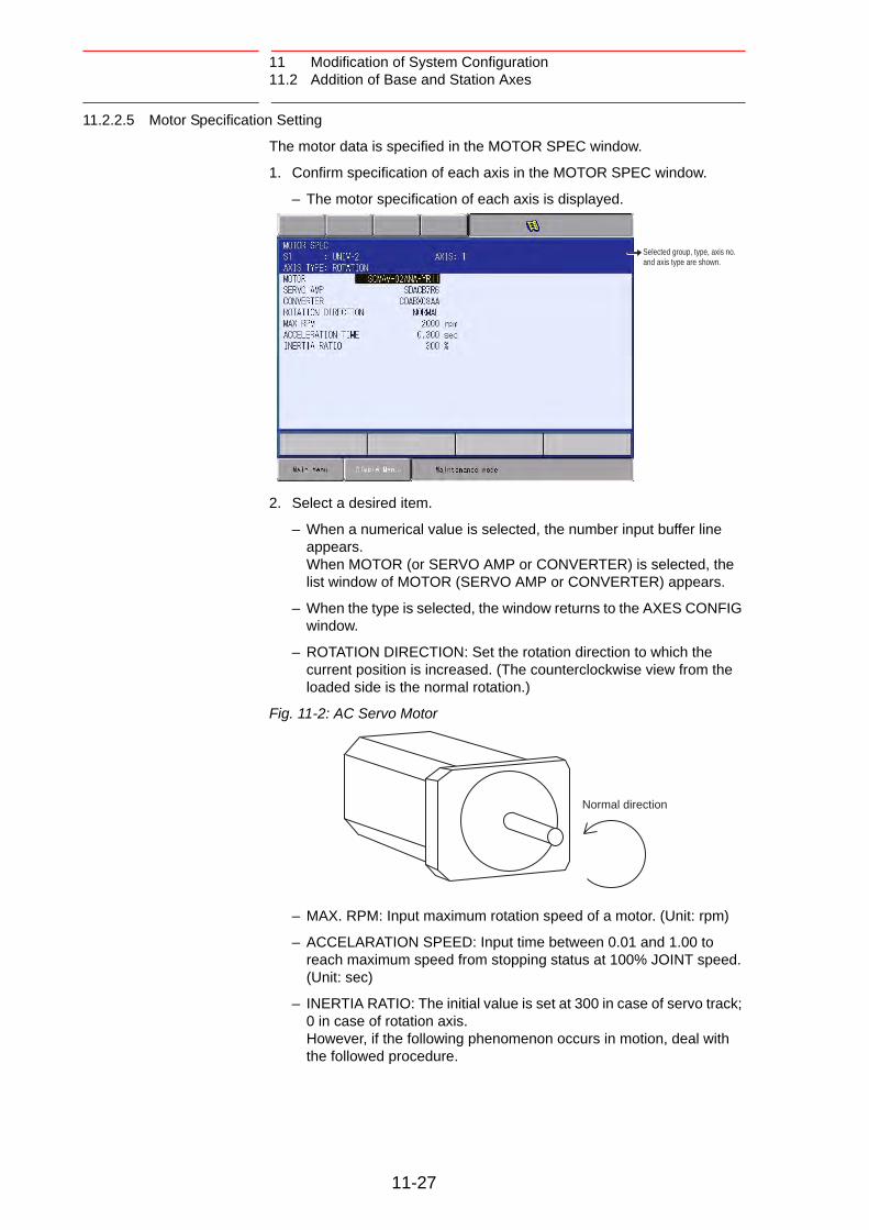
11 Modification of System Configuration11.2 Addition of Base and Station Axes
11.2.2.5 Motor Specification Setting
The motor data is specified in the MOTOR SPEC window.
1. Confirm specification of each axis in the MOTOR SPEC window.
– The motor specification of each axis is displayed.
2. Select a desired item.
– When a numerical value is selected, the number input buffer line appears.When MOTOR (or SERVO AMP or CONVERTER) is selected, the list window of MOTOR (SERVO AMP or CONVERTER) appears.
– When the type is selected, the window returns to the AXES CONFIG window.
– ROTATION DIRECTION: Set the rotation direction to which the current position is increased. (The counterclockwise view from the loaded side is the normal rotation.)
Fig. 11-2: AC Servo Motor
– MAX. RPM: Input maximum rotation speed of a motor. (Unit: rpm)
– ACCELARATION SPEED: Input time between 0.01 and 1.00 to reach maximum speed from stopping status at 100% JOINT speed. (Unit: sec)
– INERTIA RATIO: The initial value is set at 300 in case of servo track; 0 in case of rotation axis. However, if the following phenomenon occurs in motion, deal with the followed procedure.
Selected group, type, axis no. and axis type are shown.
Normal direction
11-27

11 Modification of System Configuration11.2 Addition of Base and Station Axes
– <Phenomenon 1> During motion, the axis moves unsteadily to the direction of travel. Check the motion by increasing this ratio in increments of 100.
– <Phenomenon 2> During pause, the motor makes a strange noise. Check the motion by decreasing this ratio in increments of 100.
3. Modify the settings.
CAUTION
• If the control axis configuration is changed by addition of a base axis or station axis, the internal data of the job file are also changed so that the job file data should be initialized. Initialize the job file data with procedure “File Initialize” in this manual after changing the construction.
• When the data, motion range for example, should be changed after the addition of a base axis or station axis, the change can be done in the same procedure as shown above. In this case, the control axis configuration is not changed so the job file data should not be initialized.
11-28

12 FS100L Specification
12 FS100L Specification
WARNING
• Make sure that there is no one within the manipulator’s operating range and that you are in a safe place before turning ON the FS100L power.
Injury may result from collision with the manipulator to anyone entering the manipulator’s operating range. Always press the emergency stop button immediately if there are problems.
• Observe the following precautions when performing teaching operations within the manipulator’s operating range:
– Be sure to use a lockout device to the safeguarding when going inside. Also, display the sign that the operation is being performed inside the safeguarding and make sure no one closes the safeguarding.
– Always view the manipulator from the front
– Always follow the predetermined operating procedure.
– Always have an escape plan in mind in case the manipulator comes toward you unexpectedly.
– Ensure that you have a safe place to retreat in case of emergency.
Improper or unintentional manipulator operation can result in injury.
• Before operating the manipulator, check that the SERVO ON lamp goes out when the emergency stop button on the programming pendant is pressed.
Injury or damage to machinery may result if the manipulator cannot be stopped in case of an emergency.
The emergency stop button is located on the right of the programming pendant.
12-1

12 FS100L Specification
CAUTION
• Perform the following inspection procedures prior to performing teaching operations. If problems are found, correct them immediately, and be sure that all other necessary processing has been performed.
– Check for problems in manipulator movement.
– Check for damage to the insulation and sheathing of external wires.
• Always return the programming pendant to a safe place after use.
If the programming pendant is inadvertently left on the manipulator, fixture, or on the floor, the manipulator or a tool could collide with it during manipulator movement, possibly causing injuries or equipment damage.
• Make sure that a system manager stores the key of the mode select switch on the programming pendant. After operation, the key should be removed and stored by the system manager.
Improper or unintended manipulator operation may result in injury. Also, the key or the mode select switch may be damaged if the programming pendant is dropped with the key inserted.
12-2

12 FS100L Specification12.1 Specifications of FS100L
12.1 Specifications of FS100L
Structure Free-standing, open type
Dimensions 650 (W) × 500 (H) × 550 (D) mm((H) does not include the height of caster)
Approximate mass 100kg (without built-in transformer)170kg (with built-in transformer)
Ambient temperature 0° C to +40° C (during operation)-10° C to +60° C (during transportation and maintenance)
Relative humidity 10 to 90% RH (non-condensing)
Power supply Without three-phase built-in transformer-Three-phase power supply 200/220 VAC (+10% to -15%) 50/60 Hz (±2%)With three-phase built-in transformer-Three-phase power supply 380/400/415 VAC (+10% to -15%) 50/60 Hz (±2%) (380 VAC when shipped)
Cooling system Direct cooling
Grounding Grounding resistance: 100 Ω or less, exclusive grounding1)
1 Perform grounding in accordance with all relevant local and nationalelectrical codes. The size of the ground wire must be equal to the size listed intable 4-2 “FS100L Power Capacity, Cable Size, and Breaker” atpage 4-6.
Protection class IP20 (Optional IP40)
Digital I/O NPN
Specific signals (hardware): 10 inputs and 2 outputs
General signals (standard, maximum): 28 inputs, 28 outputs (transistor: 28 outputs)
Positioning system By serial communication (absolute encoder)
Drive unit SERVOPACK for AC servomotors
Acceleration/deceleration Software servo control
Memory capacity 20000 steps, 2000 instructions
CIO ladder Max. 1500 step
Brake release The brake of each axis can be released individually by the programming pendant.
12-3

12 FS100L Specification12.2 Functions of FS100L
12.2 Functions of FS100L
Programming
Pendant
Operation
CoordinateSystem
Joint, Rectangular/Cylindrical, Tool, User Coordinates
Modification of Teaching Points
Adding, Deleting, Correcting (Robot axes and external axes respectively can be corrected.)
Inching Operation Possible
Path
Confirmation
Forward/Reverse step, Continuous feeding
Speed Adjustment Fine adjustment possible during operating or pausing
Timer Setting Possible every 0.001 s
Short-cut Function Direct-open function, Multi-window
Interface CF (CompactFlash) card slot, USB port (USB1.1) (on programming pendant), USB port (2.0) (on control circuit board), RS232C (on control circuit board), LAN (100 BASE-TX/10BASE-T) (on control circuit board) (optional)
Safety
Feature
Essential Measures
JIS (Japanese Industrial Standard)
Running Speed Limit
User definable
Enable Switch 3 position type. Servo power can be turned on at the middle position only. (Located on programming pendant)
Collision proof Frames
Cubic frame, Axis frame
Self-Diagnosis Classifies error and two types of alarms (major and minor) and displays the data
User Alarm Display
Possible to display alarm messages for peripheral device
Machine Lock Test-run of peripheral devices without robot motion
Maintenance
Function
Operation Time Display
Control power-on time, Servo power-on time, Playback time, Operation time, Work time
Alarm Display Alarm message, troubleshooting, previous alarm records
I/O Diagnosis Simulated enabled/disabled output possible
T.C.P. Calibration Automatically calibrates parameters for end effectors using a master positioner
12-4

12 FS100L Specification12.2 Functions of FS100L
Programming Programming Type
Interactive programming
Language Robot language: INFORM III
Robot Motion Control
Joint coordinates, Linear/Circular interpolations, Tool coordinates
Speed Setting Percentage for joint coordinates, 0.1mm/s units for interpolations, Angular velocity for T.C.P. fixed motion
Program Control
Instructions
Jumps, Calls, Timer, Robot stop, Execution of some instructions during manipulator motion
Variable Global variable, Local variable
Variable Type Byte type, Integer-type, Double precision-type, Real type, Position type, String type
I/O Instructions Discrete I/O, Pattern I/O processing
12-5

12 FS100L Specification12.3 Specifications of Programming Pendant
12.3 Specifications of Programming Pendant
Item Specifications
Type JZRCR-YPP03-1or JZRCR-YPP13-1
Dimensions 169 (W) × 314.5 (H) × 50 (D) mm(excluding protrusions)
Approximate mass
990 g
Material Reinforced plastic
Control device
(1) Select key (2) Axis keys (3) Numeric/application keys (4) Mode switch with a key (mode: teach, play, remote) Key type: AS6-SK-132 (manufactured by IDEC) 1) (5) Emergency stop button (6) Enable switch (7) CompactFlash card slot (CompactFlash is optional.) (8) USB port (1 port)
1 Two keys are supplied with the programming pendant.
Display 640 × 480 pixel color LCD, touch panel (Alphanumeric characters, Chinese characters, Japanese letters, etc.)
IEC protection class
IP65
Cable length Standard: 8 m, Max.: 20 m (optional)
Key sheet General (1 sheet only)
TEACHPLAY
REMOTESTART HOLD
X+R+
Y+B+
Z+T+
X-R-
Y-B-
Z -T -
8+8-
X+S+
Y+L+
Z+U+
X-S-
Y-L -
Z-U-
E+E-
SERVO ON
HIGHSPEED
FAST
SLOW
SELECT
TOOL OF0
1TOOL ON2
TOOL ONJOB
3
SMOV4 5 6
SYNCROSINGLE
7 8 9
TOOL OFJOB
ASSIST!?
AREA
SERVOON
READY
SHIFT
DIRECTOPEN
GO BACK
PAGEMULTI
LAYOUT
MAINMENU
ROBOT
EX.AXIS
ENTRY
SIMPLEMENU
TOOL SEL
COORD
DELETE INSERT
MODIFYMOTIONTYPE
INFORMLIST
USAGE
AUX
CANCEL
INTERLOCK TEST
START
BWD FWD
ENTER
SHIFT
MANUAL SPEED
1
2
3
6
4 5
8
7
12-6

12 FS100L Specification12.4 Equipment Configuration of FS100L
12.4 Equipment Configuration of FS100L
The equipment configuration of the FS100L is described below.
12.4.1 Arrangement of Units and Circuit Boards
Fig. 12-1: Equipment Configuration of FS100L
System I/O circuit boardJAPMC-IO2308R-ET1(abbreviated as LIO-08RT1)
User I/O circuit boardJAPMC-IO2308R-E(abbreviated as LIO-08R)
Machine safety circuit boardJAPMC-SF2300R-E(abbreviated as SF2300R)
Control circuit boardJEPMC-CP3201R-E(abbreviated as CPU-201R)
Back view(without the back panel)
Front view(without the front panel)
Power relay circuit boardJEPMC-PSD3007R-E
Top view(without the top panel)
Servo packJZRCR-FSV -** **
Brake control boardJANCD-YBK01-2E
JZNC-YPS01-ECPS unit
Power supply contactor unitJZRCR-YPU31 -1
ConverterSRDA-COA30A01A-E
12-7

12 FS100L Specification12.5 Arrangement of FS100L when IP40 Specification (Optional)
12.5 Arrangement of FS100L when IP40 Specification (Optional)
Following parts are added when IP40 specification (optional).
• Filters to the FS100L air inlets and exhausts.
• Caps to the FS100L fixing nuts at its side part.
For the maintenance (inspection, cleaning or filter replacement) of those added filters, refer to “FS100L MAINTENANCE MANUAL” (Manual No.: RE-CHO-A112).
Fig. 12-2: Equipment Configuration of FS100L when IP40 Specification (Optional)
Filter Cap (4 places) Cap (4 places)Filter
Filter
Back View Left Side View Front View Right Side View
Filter Filter
12-8

13 Description of Units and Circuit Boards
13 Description of Units and Circuit Boards
WARNING
• When turning ON the power to FS100L, be sure that there is no one within the manipulator’s operating range, and that you are in a safe place.
Injury may result from collision with the manipulator to anyone entering the manipulator’s operating range. Always press the emergency stop button immediately if there are problems.
• Observe the following precautions when performing teaching operations within the manipulator’s operating range:
– Be sure to use a lockout device to the safeguarding when going inside. Also, display the sign that the operation is being performed inside the safeguarding and make sure no one closes the safeguarding.
– Always view the manipulator from the front
– Always follow the predetermined operating procedure.
– Always have an escape plan in mind in case the manipulator comes toward you unexpectedly.
– Ensure that you have a safe place to retreat in case of emergency.
Improper or unintended manipulator operation may result in injury.
• Before operating the manipulator, check that the SERVO ON lamp goes out when the emergency stop button on the programming pendant is pressed.
Injury or damage to machinery may result if the manipulator cannot be stopped in case of an emergency. The emergency stop button is located on the right of the programming pendant.
13-1

13 Description of Units and Circuit Boards
CAUTION
Perform the following inspection procedures prior to performing teaching operations. If problems are found, correct them immediately, and be sure that all other necessary processing has been performed.
– Check for problems in manipulator movement.
– Check for damage to insulation and sheathing of external wires.
• Always return the programming pendant to its specified position after use.
If the programming pendant is inadvertently left on the manipulator or fixture, or on the floor, the manipulator or a tool could collide with it during manipulator movement, possibly causing injuries or equipment damage.
• Make sure that a system manager stores the key of the mode select switch on the programming pendant. After operation, the key should be removed and stored by the system manager.
Improper or unintended manipulator operation may result in injury. Also, the key or the mode select switch may be damaged if the programming pendant is dropped with the key inserted.
13-2

13 Description of Units and Circuit Boards
Cautions on Connection for Dual Input Signals
CAUTION
• Connect the switch (contact) that turns the dual signals ON and OFF simultaneously.
• If the timing that turns the two signals ON and OFF is not right, a disagreement alarm occurs. Refer to the figure below.
CAUTION
• Do not connect two signals to the same contact point.(Prepare two individual contact points)
• Since the power supply for each signal is reversed, it will short-circuit and may cause breakdown of FS100L Unit if the signals are connected to the same contact point.
Input signal 1Turn ON/OFFsimultaneouslyInput signal 2
FS100L
SwitchMachine safety circuit board
+24V
024V
CN3
A1
B1
A6
B6
1
2
11
12
CN2
Short-circuit current
The same contact
FS100L
+24V
024V
CN3
A1
B1
A6
B6
1
2
11
12
CN2
Input signal 1
Input signal 2
Machine safety circuit boardSwitch
13-3

13 Description of Units and Circuit Boards13.1 CPU Unit
13.1 CPU Unit
13.1.1 CPU Unit Configuration
CPU unit consists of a power relay circuit board, control circuit board, circuit board rack, machine safety circuit board, user I/O circuit board and system I/O circuit board.
The machine safety circuit board, user I/O circuit board and system I/O circuit board are mounted on the circuit board rack.
The power relay circuit board, control circuit board, and circuit board rack are connected by using the connectors on the side.
Fig. 13-1: CPU Unit Configuration
Machine safety circuit boardJAPMC-SF2300R-E(abbreviated as SF2300R)Control circuit board
JEPMC-CP3201R-E(abbreviated as CPU-201R)
CP3201R7-seg LEDStatus indication LED
CP3201R(CN4) USB
CP3201R(CN1) High-speedserial communication
Circuit board rackJEPMC-BUB3008R-E(8 slots in total: 4 slots used, 4 slots available)CP3201R
(Ether Net) (P.P.) Programming pendant connection
Power relay circuit boardJEPMC-PSD3007R-E
CP3201R(COM) RS232C
User I/O circuit boardJAPMC-IO2308R-E (abbreviated as LIO-08R) System I/O circuit board
JAPMC-IO2308R-ET1 (abbreviated as LIO-08RT1)
RUN ALM
HWBB1 HWBB2
13-4

13 Description of Units and Circuit Boards13.1 CPU Unit
13.1.2 Circuit Board in CPU Unit
13.1.2.1 Control Circuit Board
(JEPMC-CP3201R-E, Abbreviated as CPU-201R)
This board performs to control the entire system, display to the programming pendant, control the operating keys, control operation, and calculate interpolation.
The operation status of the FS100L is indicated by the 7-seg LED and status indication LED. (For details of the 7-seg LED and status indication LED, refer to chapter 11 “LED Indicator on Each Circuit Board” of “FS100L MAINTENANCE MANUAL”.)
This board is connected with the major axes control circuit board (SRDA-EAXA01A) via high-speed serial communication, and has a USB port (2.0) and Ethernet (100BASE-TX/10-BASE-TX).
and Ethernet (100BASE-TX/10-BASE-TX).
13.1.2.2 Power Relay Circuit Board (JEPMC-PSD3007R-E)
This is the relay board to receive the control power supply for the entire CPU unit from the CPS unit (JZNC-YPS01-E).
13.1.2.3 Circuit Board Rack (JEPMC-BUB3008R-E)
This is the rack to mount the circuit boards including optional circuit boards.
This rack is connected with the control circuit board (JEPMC-CP3201R-E) by using the connectors on the side.
The total number of slots is 8, but the circuit boards (machine safety circuit board, user I/O circuit board and system I/O circuit board) are mounted as standard. Thus, the number of available slots is 4, i.e., 4 optional circuit boards can be mounted.
NOTEPlease do not change the factory setting of RSW1 except operations which are described at chapter 9. (Factory setting is [0] )
NOTE Please do not change the factory setting of RSW2.
(Factory setting is [0])
NOTEPlease do not change the DIP switch settings of SW1 and SW2.
(Factory settings are all "OFF")
13-5

13 Description of Units and Circuit Boards13.2 Machine Safety Circuit Board
13.2 Machine Safety Circuit Board
(JAPMC-SF2300R-E, Abbreviated as SF2300R)
13.2.1 Machine Safety Circuit Board (JAPMC-SF2300R-E)
This unit contains dual processing circuits for safety signal.
It processes external safety signals with the dual processing circuits and, according to conditions, controls turning ON/OFF of the contactors for the servo power supply in the power supply contactor unit (JZRCR-YPU31⃞-1).
The functions of the machine safety circuit board include the following:
• Robot system input circuit (safety signal dual circuits)
• Protection stop (PSTOP) input circuit (dual circuits)
• Programming pendant signal PPESP, PPDSW input circuit (dual circuits)
For details of the status indication LED, refer to chapter 11 “LED Indicator on Each Circuit Board” of “FS100L MAINTENANCE MANUAL”.
Status indication LED
(CN2)PPESP/PPDSW
(CN3)The robot system signal I/O connector CN2 cable connection(safety signal)
(CN4)Contactor control signal output
(CN5)Overrun OT1, OT2
(CN6)24 V input for safety signal I/O
13-6

13 Description of Units and Circuit Boards13.2 Machine Safety Circuit Board
13.2.2 Connection for Robot System Input/Output Signal
A connector to input/output the robot system signal is prepared on the right side of the CPU unit of the FS100L. (Connector number: CN2)
For connection, refer to the connection diagram of each item.
Table 13-1: Pin Assignment of Robot System Signal Input/Output Connector (CN2)
Controller-side connector: 17JE-13250-02(D4A)A, manufacturer: DDK Note: fitting stud M2.6 Mating connector: 17JE-23250-02(D8A)-CG (connector with hood), manufacturer: DDK
* Upon shipment of the FS100L, a dummy connector which short-circuits each system signal is attached.
Pin No. Signal Name Description
1 SAFF_1+ Safeguarding (safety plug) (first system) * Upon shipment of the FS100L, this is short-circuited with a jumper cable in the dummy connector.
2 SAFF_1-
3 PSTOP_1+ Protection stop (first system) * Upon shipment of the FS100L, this is short-circuited with a jumper cable in the dummy connector.
4 PSTOP_1-
5 EXESP_1+ External emergency stop (first system) * Upon shipment of the FS100L, this is short-circuited with a jumper cable in the dummy connector.
6 EXESP_1-
7 ESPOUT_1+ Emergency stop output (first system)*Do not short-circuit. 8 ESPOUT_1-
9 PPESP3+ Programming pendant emergency stop output (first system)10 PPESP3-
11 SAFF_2+ Safeguarding (safety plug) (second system) * Upon shipment of the FS100L, this is short - circuited with a jumper cable in the dummy connector.
12 SAFF_2-
13 Not used
14 PSTOP_2+ Protection stop (second system) * Upon shipment of the FS100L, this is short - circuited with a jumper cable in the dummy connector.
15 PSTOP_2-
16 EXESP_2+ External emergency stop (second system) * Upon shipment of the FS100L, this is short - circuited with a jumper cable in the dummy connector.
17 EXESP_2-
18 ESPOUT_2+ Emergency stop output (second system)*Do not short-circuit. 19 ESPOUT_2-
(CN2)Robot system signalinput/output connector
13-7

13 Description of Units and Circuit Boards13.2 Machine Safety Circuit Board
* To input a system signal, supply a new connector for the signal. To a signal not used, connect a jumper cable similarly to when the FS100L is shipped.
13.2.2.1 Connection for Protection Stop (PSTOP) Signal
Connect this signal line when using the function to immediately turn OFF the servo power for safety protection when the servo power of the FS100L robot system is turned ON. (Stop category 0)
This signal is not used as standard, and a jumper cable is connected in the dummy connector.
To use this signal, supply a new connector and perform wiring.
To a robot system signal which is not used, connect a jumper cable similarly to when the FS100L is shipped.
The dual inputs of the protection stop signal are used for safety. Thus, connect the switch (contact) that turns the dual signals ON and OFF simultaneously.
If only one of the signals is turned ON, an alarm occurs.
Fig. 13-2: Connection for Protection Stop Signal
20 PPESP4+ Programming pendant emergency stop output (second system)21 PPESP4-
22 Not used
23 Not used
24 Not used
25 Not used
Pin No. Signal Name Description
3
4
14
15
A2
B2
A7
B7
Turn ON/OFFsimultaneously
FS100L
CN3
PSTOP_1+
PSTOP_1-
PSTOP_2+
PSTOP_2-
CN2Protection stop signal
Machine safety circuit board
13-8

13 Description of Units and Circuit Boards13.2 Machine Safety Circuit Board
13.2.2.2 Connection for Safeguarding (Safety Plug) (SAFF) Signal
This is the signal to turn OFF the servo power when the safeguarding opens. (Stop category 1)
Connect the interlock signal of the safety plug, etc. mounted on the door of safeguarding.
When the interlock signal is input, the servo power turns OFF, and the servo power cannot be turned ON after that.
This is disabled in the teach mode.
Upon shipment of the FS100L, a jumper cable is connected in the dummy connector.
To use the robot, supply a new connector and perform wiring of the safeguarding signal.
To a robot system signal which is not used, connect a jumper cable similarly to when the FS100L is shipped.
Fig. 13-3: Connection for Safeguarding (Safety Plug) Signal
CAUTION
• Upon shipment of the FS100L, this signal is connected by a jumper cable in the dummy connector. To use the signal, make sure to supply a new connector, and then input it.
If the signal is input with the jumper cable connected, it does not function, which may result in personal injury or equipment damage.
Turn ON/OFFsimultaneously
FS100L
SAFF_1+
SAFF_1-
SAFF_2+
SAFF_2-
1
2
11
12
A1
B1
A6
B6
CN3 CN2Safeguarding (safety plug) signal
Machine safety circuit board
13-9

13 Description of Units and Circuit Boards13.2 Machine Safety Circuit Board
Installation example of safety plug
Install a safeguarding and a door with the interlock function around the manipulator so that an operator must open the door to enter and the interlock function stops the robot operation when the door opens.
The safety plug input signal is the signal to connect this interlock signal.
Fig. 13-4: Installation Example of Safety Plug
When the servo power is ON, input the interlock signal to turn OFF the servo power. (The servo power cannot be turned ON while the interlock signal is input.)
Note that the servo power does not turn OFF in the teach mode. (The servo power can be turned ON even while the interlock signal is input.)
Manipulator’s range of motionSafeguarding
Safety doorFS100L
Safety plug
Portable plug
Emergencystop button
Servo ON lamp(optional)
13-10

13 Description of Units and Circuit Boards13.2 Machine Safety Circuit Board
13.2.2.3 Connection for External Emergency Stop (EXESP) Signal
This signal is used to connect the emergency stop switch of an external device, etc.
If the signal is input, the servo power is turned OFF and the job is stopped. (Stop category 1) While the signal is input, the servo power cannot be turned ON.
Upon shipment of the FS100L, a jumper cable is connected in the dummy connector.
To use the this signal, supply a new connector and perform wiring of the external emergency stop signal.
To a robot system signal which is not used, connect a jumper cable similarly to when the FS100L is shipped.
Fig. 13-5: Connection for External Emergency Stop Signal
CAUTION
• Upon shipment of the FS100L, this signal is connected by a jumper cable in the dummy connector. To use the signal, make sure to supply a new connector, and then input it.
If the signal is input with the jumper cable connected, it does not function, which may result in personal injury or equipment damage.
• In case the programming pendant is not used, an emergency stop button should be prepared in the system and wire the extenral emergency stop signal.
Injury or damage to machinery may result if the manipulator dose not stop due to the failure in preparatin of the emergency stop button.
Turn ON/OFFsimultaneously
FS100L
EXESP_1+
EXESP_1-
EXESP_2+
EXESP_2-
5
6
16
17
A3
B3
A8
B8
CN3 CN2External emergency stop signal
Machine safety circuit board
13-11

13 Description of Units and Circuit Boards13.2 Machine Safety Circuit Board
13.2.2.4 Connection for Emergency Stop Output (ESPOUT) Signal
This signal outputs, as dual signals, the signal status of the emergency stop of the programming pendant, the external emergency stop, and the safeguarding (safety plug) in the automatic operation mode.
This signal can be used to check the signal status of the emergency stop of the programming pendant, the external emergency stop, and the safeguarding (safety plug) in the automatic operation mode by using an external safety device, etc. (for monitor use only)
To use this signal, supply a new connector and perform wiring.
Fig. 13-6: Connection for Emergency Stop Output Signal
* Output capacity: 24 VDC, 50 mA max.
CAUTION
• This signal is for monitor use.Unable to use the power shutdown for the external devices as safety signal.
External device
FS100L
ESPOUT_1+
ESPOUT_1-
ESPOUT_2+
ESPOUT_2-
Emergency stopoutput signal
Machine safety circuit board
7
8
18
19
A4
B4
A9
B9
CN3 CN2
13-12

13 Description of Units and Circuit Boards13.2 Machine Safety Circuit Board
13.2.2.5 Connection for Programming Pendant Emergency Stop Contact Output (PPESP) Signal
To an external device, a programming pendant emergency stop button contact signal is output.
This emergency stop output is always valid despite ON/OFF of the main power supply of the FS100L. (status output signal: normally closed contact)
Fig. 13-7: Connection of Emergency Stop Button Contact Output Signal
CAUTION
• Apply less voltage of 24VDC and less current of 0.5A .
Failure to observe this caution may damage to machinery.
PPESP3+
PPESP3-
PPESP3+
PPESP3-
EXT
PPESP4+
PPESP4-
PPESP4+
PPESP4-
9
10
20
21
Programming pendant
Emergency stop button
CN2
13-13

13 Description of Units and Circuit Boards13.2 Machine Safety Circuit Board
13.2.3 Connection for External Axis Overrun
If the overrun input of an external axis, etc. other than the manipulator is needed, perform connection as shown in fig. 13-8 “Connection for External Axis Overrun Signal (1-External Axis)” .
If the signal is input, the servo power is turned OFF and the job is stopped. While the signal is input, the servo power cannot be turned ON.
The dual inputs of the external axis overrun signal are used for safety. Thus, connect the switch (contact) that turns the dual signals ON and OFF simultaneously.
If only one of the signals is turned ON, an alarm occurs.
For the standard specification (without external axis), this signal cannot be used because the connectors for input (EX-X11, EX-X12) are not mounted.
Fig. 13-8: Connection for External Axis Overrun Signal (1-External Axis)
Turn ON/OFFsimultaneously
Back panelExternal axis overrun signal
Relay BOX
Machine safety circuit boardCN5 EX- X11
OT2_1+ 25
26
27
28
A2
B2
A4
B4
OT2_1-
OT2_2+
OT2_2-
OT□-1
ROT□-1
OT□-
ROT□-
FS100L
13-14

13 Description of Units and Circuit Boards13.3 CPS Unit (JZNC-YPS01-E)
13.3 CPS Unit (JZNC-YPS01-E)
This unit (JZNC-YPS01-E) supplies the DC power (DC5V, DC24V) for control (system, I/O, brake).
Fig. 13-9: CPS Unit JZNC-YPS01-E
VUTSRQPNMLKJHGFEDCBA
302928272614
252423222120191817161513121110090807060504030201
C90AD XXXXX
MADE IN JAPANFuji Electric Hi-Tech Corp.
DATENO.
POWER SUPPLYCPS-520F
YYYY-MM
VUTSRQPNMLKJHGFEDCBA
302928272614
252423222120191817161513121110090807060504030201
CN154(+24V1/+24V2)
CN159
CN158(+5V)
CN155(+24V1/+24V2)
(+24V2)CN156/157
(+24V3)CN153
(REMOTE)CN152
(ALM)SOURCE
OHT
INPUT
FAN+24V+5VP-ON
50/60Hz
(AC IN)CN151
200-240V AC
3.4A-2.8A
(CN159)Alarm Output
(CN158)+5V
(CN156/CN157)+24V2 Power Supply Output
(CN154/CN155)+24V1/+24V2 Power Supply Output
(CN153)+24V3 Power Supply Output
(CN152)Remote Control
(CN151)AC Power Supply Input
Monitor�Alarm Display
Items Specifications
Input Rating Input Voltage: 200/220VACVoltage Fluctuation Range: +10% to -15% (170 to 242VAC)Frequency: 50/60Hz ± 2Hz (48 to 62Hz)
Output Voltage DC + 5V DC +24V (24V1: System, 24V2: I/O, 24V3: Brake)
Indicator
DISPLAY Color Status
SOURCE Green Lights with power supply input.Lights out when internal live part completes discharge.(Power supply status: being input)
POWER ON Green Lights when PWR_OK output signal is ON. (Power supply status: being output)
+5V Red Lights with +5V over-current(ON when abnormal)
+24V Red Lights with +24V over-current(ON when abnormal)
FAN Red Lights when FAN error occurs.
OHT Red Lights when unit interior overheats
13-15

13 Description of Units and Circuit Boards13.4 Brake Control Board (JANCD-YBK01-2E)
13.4 Brake Control Board (JANCD-YBK01-2E)
13.4.1 Brake Control Board (JANCD-YBK01-2E)
Brake Control Board controls ON/OFF of the brakes (Robot + external axes) according to the command signal from Major Axes Control Circuit Board (SRDA-EAXA01□).
(CN405)
(CN404)
(CN400)
(CN402) F1:Fuse3.15A/250V
(CN403)Brake Power Supply Input
Brake Output
Contactor Interlock Input
(CN401)Brake Release Switch Connect
For Switching External Power Supply
Brake Command Input
13-16

13 Description of Units and Circuit Boards13.5 Power Supply Contactor Unit (JZRCR-YPU31 ⃞ -1)
13.5 Power Supply Contactor Unit (JZRCR-YPU31 ⃞ -1)
The power supply contactor unit (JARCR-YPU31 ⃞ -1) consists of the power supply contactor circuit board (JARCR-YPC01-1), the contactor (1KM, 2KM) for servo power and the line filter (1Z). It turns the contactor servo power ON and OFF using the signal for servo power control from the machine safety circuit board and supplies power (3-phase AC200/220V) to the converter.
The power supply (single phase AC200/220V) is supplied to the CPS unit via the line filter.
Fig. 13-10: Power Supply Contactor Unit Configuration (JZRCR-YPU31 ⃞ -1)
(CN608)
(CN607)GP25 (2.5A 250V)
(4FU), (3FU)
0218010P(10A 250V)
(CN602)
(2FU), (1FU)
(CN606)
(CN605,CN604,CN603)
(CN601)
Contactor Control Input
AC Cooling Fan
Main Power Supply Input
Brake Interlock Output
Converter Output
AC Control Power Supply
Fuse for AC Cooling Fan
Fuse for AC Control Power Supply
13-17

13 Description of Units and Circuit Boards13.6 Converter
13.6 Converter
This exchanges the power supply (3-phase: AC200/220V) supplied by the power supply contactor unit for DC power supply and supplies the power to PWM amplifiers for each axis.
Fig. 13-11: Converter
(CN551)
(CN556)
(CN558)
(CN557)
(CN555)
(CN554)
(CN553)
Grounding Detection InputGround Terminal
Regenerative Resister
Main Circuit Power Supply Input
Monitor Alarm Display LED
Converter Control Signal
Control Power Supply Input
(CN552A) Control Power SupplyOutput for 6-Axis Amplifier
(CN552A) Control Power SupplyOutput for External Axis Amplifier
Charge Lamp
Converter
Main Circuit Output for External Axis
Main Circuit Power Supply Output
Upper Grip
13-18

13 Description of Units and Circuit Boards13.7 SERVOPACK
13.7 SERVOPACK
A SERVOPACK consists of a PWM amplifier and the major axes control circuit board. PWM amplifiers vary depending on the type of the manipulators.
13.7.1 PWM Amplifier
This exchanges the DC power supply supplied by the converter for a 3-phase motor power source and outputs to each servo motor.
Table 13-2(a): Configuration of PWM Amplifier
Configuration Device MH50 MH80
Model Model
SERVOPACK JZRCR-FSV04-11 JZRCR-FSV05-11
PWMAmplifier
S SRDA-SDA71A01A-E SRDA-SDA71A01A-E
L SRDA-SDA71A01A-E SRDA-SDA71A01A-E
U SRDA-SDA35A01A-E SRDA-SDA71A01A-E
R SRDA-SDA14A01A-E SRDA-SDA14A01A-E
B SRDA-SDA14A01A-E SRDA-SDA14A01A-E
T SRDA-SDA14A01A-E SRDA-SDA14A01A-E
Table 13-2(b): Configuration of PWM Amplifier
Configuration Device MH165MH200
MH215MH250
Model Model
SERVOPACK JZRCR-FSV06-11 JZRCR-FSV06-11
PWMAmplifier
S SRDA-SDA71A01A-E SRDA-SDA71A01A-E
L SRDA-SDA71A01A-E SRDA-SDA71A01A-E
U SRDA-SDA71A01A-E SRDA-SDA71A01A-E
R SRDA-SDA35A01A-E SRDA-SDA35A01A-E
B SRDA-SDA21A01A-E SRDA-SDA35A01A-E
T SRDA-SDA21A01A-E SRDA-SDA35A01A-E
Table 13-2(c): Configuration of PWM Amplifier
Configuration Device MPL80
Model
SERVOPACK JZRCR-FSV04-11
PWMAmplifier
S SRDA-SDA71A01A-E
L SRDA-SDA71A01A-E
U SRDA-SDA35A01A-E
- SRDA-SDA14A01A-E
B SRDA-SDA14A01A-E
T SRDA-SDA14A01A-E
13-19

13 Description of Units and Circuit Boards13.7 SERVOPACK
Fig. 13-12: Configuration of Servo Pack: MH50, MH80, MPL80, MPK50
Table 13-2(d): Configuration of PWM Amplifier
Configuration Device MPK50
MPL100MPL160MPL300
Model Model
SERVOPACK JZRCR-FSV05-11 JZRCR-FSV06-11
PWMAmplifier
S SRDA-SDA71A01A-E SRDA-SDA71A01A-E
L SRDA-SDA71A01A-E SRDA-SDA71A01A-E
U SRDA-SDA71A01A-E SRDA-SDA71A01A-E
R SRDA-SDA14A01A-E SRDA-SDA35A01A-E
- SRDA-SDA14A01A-E SRDA-SDA21A01A-E
- SRDA-SDA14A01A-E SRDA-SDA21A01A-E
EAXA Board
Ground TerminalEAXA Base
EAXA Base FixingScrew (bottom)
(CN516)
(CN518)
(CN517)
(CN515)
I/O Communication
I/O Communication
Control Communication
Control Communication
(CN512)
(CN508)
(CN509)
Encoder Signal
Control Power Supply Input
SHOCK Signal Input
Control Power SupplyOutput for Converter
EAXA BaseFixing Screw (top)
(CN510)
(CN502)
(CN513)
(CN507)
(CN511)
(CN514)
(CN501)
(CN503)
(CN504)
(CN505)
(CN506)
Upper Grip
Brake Control Signal
Safety Unit I/F
Direct-in
Converter Control Signal
AMP1 PWM Signal
AMP4 PWM Signal
AMP3 PWM Signal
AMP6 PWM Signal
AMP5 PWM Signal
AMP2 PWM Signal
EAXA BaseFixing Screw (top)
PWM Signal
Motor Power Output
Amplifier Main CircuitPower Supply
Amplifier ControlPower Supply
(AMP1,3,5-CN583)
(AMP1,3,5-CN582)
(AMP1,3,5-CN581)
(AMP1,3,5-CN584)
Motor Power Output
Amplifier Main Circuit Power Supply
Amplifier Control Power Supply
(AMP2,4,6-CN583)
(AMP2,4,6-CN582)
PWM Signal (AMP2,4,6-CN581)
AMP6
AMP4
AMP2
AMP1
AMP3
AMP5
Lower Grip Lower Grip
(EAXA Base is closed) (EAXA Base is opened)
13-20

13 Description of Units and Circuit Boards13.7 SERVOPACK
Fig. 13-13: Configuration of Servo Pack: MH165, MH200, MPL100, MPL160, MPL300
Fig. 13-14: Configuration of Servo Pack: MH215, MH250
(CN502)
(CN513)
(CN507)
(CN511)
(CN514)
(CN501)
(CN503)
(CN504)
(CN505)
(CN506)
(CN516)
(CN518)
(CN517)
(CN515)
(CN512)
(CN508)
(CN509)
Ground Terminal
Encoder Signal
Control Power Supply Input
SHOCK Signal Input
Control Power SupplyOutput for Converter
I/O Communication
EAXA BaseFixing Screw (top)
I/O Communication
Control Communication
Control Communication
EAXA Base
EAXA Base FixingScrew (bottom)
Lower Grip
Upper Grip
Brake Control Signal
Safety Unit I/F
Direct-in
Converter Control Signal
AMP1 PWM Signal
AMP4 PWM Signal
AMP3 PWM Signal
AMP6 PWM Signal
AMP5 PWM Signal
AMP2 PWM Signal
EAXA BaseFixing Screw (top)
Lower Grip
(EAXA Base is closed) (EAXA Base is opened)
(CN510)
EAXA Board
PWM Signal
Motor Power Output
Amplifier Main CircuitPower Supply
Amplifier ControlPower Supply
(AMP1,3,5-CN583)
(AMP1,3,5-CN582)
(AMP1,3,5-CN581)
(AMP1,3,5-CN584)
AMP1
AMP3
AMP5
Motor Power Output
Amplifier Main Circuit Power Supply
Amplifier Control Power Supply
(AMP2,4,6-CN583)
(AMP2,4,6-CN582)
(AMP2,4,6-CN584)
AMP6
AMP2
AMP4
PWM Signal (AMP2,4,6-CN581)
13-21

13 Description of Units and Circuit Boards13.7 SERVOPACK
13.7.2 Major Axes Control Circuit Board (SRDA-EAXA01□)
The major axes control circuit board (SRDA-EAXA01□) controls the servomotors of the manipulator’s six axes.
It also controls the converter and the PWM amplifiers.
Mounting an optional external axes control circuit board (SRDA-EAXB01□) makes it possible to control the servomotor of up to eight axes, including the robot axes.
The major axes control circuit board (SRDA-EAXA01□) also has the following functions.
• Brake Power Supply Control Circuit
• Shock sensor (shock) input circuit
• Direct-in circuit
Fig. 13-15: Major Axes Control Circuit Board (SRDA-EAXA01□)
(CN513)
(CN516)
(CN512)
(CN515)
(CN508)
(CN509)
(CN505)
(CN511)
(CN514)
(CN507)
(CN506)(CN506)(CN506)
AMP2 PWM Signal(CN502)
(CN501)AMP1 PWM Signal
AMP3 PWM Signal(CN503)
AMP4 PWM Signal(CN504)
AMP6 PWM Signal
AMP5 PWM Signal
SHOCK Signal Input
Control Power Supply Input
Encoder Signal
Control Communication
Control Communication
Brake Control Signal
Manual Brake Release Signal
Direct-in
Converter Control Signal
Converter Power Supply Output(CN510)
13-22

13 Description of Units and Circuit Boards13.7 SERVOPACK
13.7.3 Connection for Direct-in Signal
This signal is used to input responsive signals when using the search function, etc.
A connector (connector No.: CN211) for inputting Direct-in signal is prepared at the right side of the CPU unit of FS100L.
Figure below shows an example of Direct-in signal. Prepare the accordant connector when input the signal to Direct-in.
Fig. 13-16: Example Connection for Direct-in Signal (AXDIN1 to AXDIN6)
(CN211)Direct-in Signal Input
B3B1024V
A4B4A5B5A6A3A1+24V
113
234567
CN514
AXD IN1
AXD IN2
AXD IN3
AXD IN4
AXD IN5
AXD IN6
(14 and 15 are also available)
FS100L
CN211
Major axes control circuit board
Mating connector:17JE-23150-02(D8A)-CG(manufacturer: DDK)
Direct-in 1Direct-in 2Direct-in 3Direct-in 4Direct-in 5Direct-in 6
(11 and 12 are also available)10
Connect a jumber cable.
13-23

13 Description of Units and Circuit Boards13.8 System I/O Circuit Board
13.8 System I/O Circuit Board
(JAPMC-IO2308R-ET1, Abbreviated as LIO-08RT1)
The System I/O circuit board processes system I/O signals such as alarm signal of the CPS unit, motor cooling fan control signal and servo ON lamp signal.
(CN1)Specific I/O
(CN2)Specific I/O
(CN3)Power Supply (+24V) for I/O Input
13-24

13 Description of Units and Circuit Boards13.9 User I/O Circuit Board
13.9 User I/O Circuit Board
JAPMC-IO2308R-E, Abbreviated as LIO-08R)
The FS100L has one user I/O circuit board (JAPMC-IO2308R-E) in its CPU unit as standard.
The user I/O circuit board (JAPMC-IO2308R-E) has 2 connectors for digital input/output (robot user input/output).
28 inputs and 28 outputs are available. System input/output and user input/output can be used when allocating these inputs and outputs.
The system input/output is the signal with a function specified in advance. It is mainly used to control the manipulator and related devices as a system from the external control device such as a jig controller or a integrated controller, etc.
The user input/output is mainly used in the job of manipulator motion as the timing signal between the manipulator and peripheral devices.
For the details of allocation, refer to fig. 13-19(a) “Connection Diagram of User Input/Output Connector (CN1) of User I/O Circuit Board (JAPMC-IO2308R-E)” at page 13-31 and fig. 13-19(b) “Connection Diagram of System Input/Output Connector (CN2) of User I/O Circuit Board (JAPMC-IO2308R-E)” at page 13-32.
NOTERegarding the user I/O circuit board for the FS100L (JAPMC-IO2309R-E, abbreviated as LIO-09R), refer to chapter 13.10 “User I/O Circuit Board (Optional)” at page 13-37.
(CN1)User input/output connector:16 inputs and 16 outputs
(CN2)System input/output connector:12 inputs and 12 outputs
(CN3)Power supply for I/O (+24V) input
13-25

13 Description of Units and Circuit Boards13.9 User I/O Circuit Board
In addition to user input/output, status of LIO-08R can be entered to the external input signal.
Logical number Signal name Description
Bit content ‘1’ ‘0’
20050 24V_CHK1) DC24VLow voltage detection
Normal Abnormal(Voltage drop or disconnection of external fuse)
20051 1 (FIXED) 1 (FIXED)
20052 1 (FIXED) 1 (FIXED)
20053 1 (FIXED) 1 (FIXED)
20054 1 (FIXED) 1 (FIXED)
20055 1 (FIXED) 1 (FIXED)
20056 MOST1 Module status1 Normal Abnormal
20057 OSC_CHK Oscillator stop detection
Abnormal Normal
20060 MOST Module status Abnormal Normal
20061 1 (FIXED) 1 (FIXED)
20062 1 (FIXED) 1 (FIXED)
20063 1 (FIXED) 1 (FIXED)
20064 1 (FIXED) 1 (FIXED)
20065 1 (FIXED) 1 (FIXED)
20066 1 (FIXED) 1 (FIXED)
20067 1 (FIXED) 1 (FIXED)
1 There is an lower voltage detection for the blown detection of DC24V power supply external fuse. When theinput voltage is lower than 15V, DC24V lower voltage detection of the status input signal would be an error.
13-26

13 Description of Units and Circuit Boards13.9 User I/O Circuit Board
13.9.1 Connection for External Power Supply for Input/Output
As standard, the input/output power supply is the internal power supply.
The FS100L can use the internal power supply of approx. 1 A, 24 VDC for input/output. This internal power supply is protected by the fuse (F14: 1 A) on the inside left of the FS100L.
To use the FS100L with an external power supply, perform connection as follows:
1. Remove the cable connected to the power supply connector (CN3) of the user I/O circuit board from the connector. Make sure to insulate the removed cable.
2. Connect the external power supply to the power supply connectors of the user I/O circuit board by connecting +24V to CN3-2 and 0V to CN3-1.
To prevent burnout at short circuit of the 24V power supply or short circuit of the output, use an external fuse in the 24V line.
For the details of external fuse, refer to chapter 13.9.2 “Protection by External Fuse” at page 13-28.
Fig. 13-17: Connection for Power Supply for Input/Output
Internal Power Supply(factory-set)
External Power Supply
CPS unit(JZNC-YPS01-E)
CPS unit(JZNC-YPS01-E)
(User supplied)
External power supply
Remove the pre-connectedcable from CN3 of the userI/O circuit board, and insulate it. User I/O circuit board
(JAPMC-IO2308R-E)User I/O circuit board(JAPMC-IO2308R-E)
+24V
024V
FS100L
CN3 CN3
FS100L
UnusedCN156 +24V
1Amax F14:1ACN156
+24V/1A
024V
13-27

13 Description of Units and Circuit Boards13.9 User I/O Circuit Board
13.9.2 Protection by External Fuse
The user I/O circuit board (JAPMC-IO2308R-E) does not have a built-in protection device (fuse) for short circuit of the 24 VDC power supply or short circuit of the output, etc.
To prevent burnout, use an external fuse (rated current: 1 A, fast-blow fuse) in the +24V line of external power supply.
The user I/O circuit board has a built-in circuit to detect if the external fuse for the 24 VDC power supply is blown.
Voltage drop of the 24 VDC power supply or a blown external fuse, etc. is detected as an error.
13.9.2.1 Protection by External Fuse in Common Line of Output Signal
If the output current is too large for the rated current (1 A) of the external fuse for the 24 VDC power supply, perform the followings:
• Increase the capacity of the external fuse for the 24 VDC power sup-ply up to the maximum of 2 A. (Use a fast-blow fuse.)
• Add an external fuse in the common line of the output signal.
For CN1, connect an external fuse (fast-blow fuse) with the rated current of 1 A for every 8 outputs.
For CN2, connect an external fuse (fast-blow fuse) with the rated current of 1 A for every 6 outputs.
NOTE
• The FS100L can use the internal power supply of approx. 1 A, 24 VDC for input/output. To use current exceeding the above, or to insulate between the inside and the outside, use the external 24 V power supply.
• Install the external power supply outside the controller to prevent external noise from entering the inside of the con-troller.
Do not connect the power lines from the external power supply to the terminals CN3-1 and CN3-2 if the connection is set for using the internal power supply (with the pre-con-nected cable connected). The internal power supply and the external power supply interfere with each other, which may result in equipment fail-ure.
13-28

13 Description of Units and Circuit Boards13.9 User I/O Circuit Board
Fig. 13-18: Example Connection for External Fuse in Common Line of Output Signal
024V
+24V
13
10
2
1
+24V
32
15
36
16
024V
FS100L
User I/O circuit board(JAPMC-IO2308R-E)
Output common fuse
Output common fuse
Load
Load
Load
Load
1A (fast-blow)
1A (fast-blow)
2A (fast-blow)
External power supply
OUT0
OUT5
OUT6
OUT11
CN3
CN2
13-29

13 Description of Units and Circuit Boards13.9 User I/O Circuit Board
13.9.3 Input/Output Connector (CN1, CN2)
Followings are the types of the input/output connectors (CN1, CN2) of the user I/O circuit board (JAPMC-IO2308R-E).
13.9.3.1 User Input/Output Connector (CN1)
13.9.3.2 System Input/Output Connector (CN2)
Item Description
Used connector 10250-52A3PL (manufacturer: Sumitomo 3M Limited)
Mating connector 10150-3000PE (manufacturer: Sumitomo 3M Limited)10350-52A0-008 (manufacturer: Sumitomo 3M Limited)10350-52F0-008 (manufacturer: Sumitomo 3M Limited)
Connector bodyShell, thumbscrew lock typeShell, quick-release latching type
Item Description
Used connector 10236-52A3PL (manufacturer: Sumitomo 3M Limited)
Mating connector 10136-3000PE (manufacturer: Sumitomo 3M Limited)10336-52A0-008 (manufacturer: Sumitomo 3M Limited)10336-52F0-008 (manufacturer: Sumitomo 3M Limited)
Connector bodyShell, thumbscrew lock typeShell, quick-release latching type
13-30

13 Description of Units and Circuit Boards13.9 User I/O Circuit Board
Fig. 13-19(a): Connection Diagram of User Input/Output Connector (CN1) of User I/O Circuit Board (JAPMC-IO2308R-E)
User I/O circuit board (JAPMC-IO2308R-E)
Buffer
LogicalNo.
Connectorpin No. Pin No. Name Signal
Each point24 VDC4.1 mA max.
Each point24 VDC100 mA max.
Externalpower supply
Internalpower supply
CPS unit (JZNC-YPS01-E)
* To use the external power supply, remove the cable connected to the power supply connector (CN3) of the user I/O circuit board from the connector. Make sure to insulate the removed cable.
LoadLoadLoadLoadLoadLoadLoadLoadLoadLoadLoadLoadLoadLoadLoadLoad
Input common 3Input common 4User input IN01User input IN02User input IN03User input IN04User input IN05User input IN06User input IN07User input IN08User input IN09User input IN10User input IN11User input IN12User input IN13User input IN14User input IN15User input IN16
User output OT16
User output OT01User output OT02User output OT03User output OT04User output OT05User output OT06User output OT07User output OT08User output OT09User output OT10User output OT11User output OT12User output OT13User output OT14User output OT15
Input common 3_24VInput common 4_24VInput common 3_0VInput common 4_0V+24V for output load+24V for output load+24V for output load+24V for output load+24V for output load
FS100L
13-31

13 Description of Units and Circuit Boards13.9 User I/O Circuit Board
Fig. 13-19(b): Connection Diagram of System Input/Output Connector (CN2) of User I/O Circuit Board (JAPMC-IO2308R-E)
User I/O circuit board (JAPMC-IO2308R-E)
Buffer
Each point24 VDC4.1 mA max.
Each point24 VDC100 mA max.
Externalpower supply
CPS unit (JZNC-YPS01-E)
Internalpower supply
* To use the external power supply, remove the cable connected to the power supply connector (CN3) of the user I/O circuit board from the connector. Make sure to insulate the removed cable.
LoadLoadLoadLoadLoadLoadLoadLoadLoadLoadLoadLoad
GND
GND
024V024V
+24V024V
+24V024V
+24V
GND
GND
FS100L
CN3
CN156
CN2
20016
20014
20012
20010
30011
30013
30015
30017
20015
20013
30010
30012
30014
30016
30020
15
3002330022
2
3214226
1316
102811291432153317
1836
927
IN
INININININ
DI_00
DI_02DI_03DI_04DI_05DI_06
DO_00DO_01DO_02DO_03DO_04DO_05DO_06DO_07DO_08
DO_10DO_11
OUTOUTOUTOUTOUTOUTOUTOUTOUT
OUTOUT
DICOM1DICOM2
CN2_+24VCN2_+24V
DICOM1_24VDICOM2_24VDICOM1_0VDICOM2_0V
1923
CN2_+24V31
20022
20020
20023
20021
20017 24725826
INININININ
DI_07DI_08DI_09DI_10DI_11
20011 20 INDI_01
30021 35 DO_09 OUT
LogicalNo.
Connectorpin No. Pin No. Name Signal
Input common 1Input common 2External startExternal holdCall master jobAlarm/error resetExternal servo ONSelect play modeSelect teach modeDigital input 7Digital input 8Digital input 9Work prohibitedDigital input 11
RunningServo in ONTop of master jobAlarm/error occurredBattery alarmRemote mode selectedPlay mode selectedTeach mode selectedIn cube 1Digital output 9Work home positionIntermediate start OK
Input common 1_24VInput common 2_24VInput common 1_0VInput common 2_0V+24V for output load+24V for output load+24V for output load
13-32

13 Description of Units and Circuit Boards13.9 User I/O Circuit Board
Table 13-3: System Input
Logical Number Input Name/Function
20010 EXTERNAL STARTFunctions the same as the [START] button on the programming pendant. Only the rising edge of the signal is valid. It starts robot operation (playback). This signal is invalid if external start is prohibited from the playback condition display.
20011 EXTERNAL HOLDFunctions the same as the [HOLD] button on the programming pendant, and is used when connecting a temporary stop switch of an external control device, etc. Connect a break-contact switch to this signal. When this signal is input (OFF), the JOB is stopped. During the input, the operation cannot be started and the axes cannot be operated. Also, while this signal is OFF, the [HOLD] button on the programming pendant lights up.
Note that this signal is disabled as the default setting. To enable this signal, enable “EXTERNAL HOLD” in the {OPERATE ENABLE} under the main menu {SETUP} of the programming pendant in the management mode. For details, refer to chapter 13.9.4 “Enabling External Hold” at page 13-34.
20012 CALL MASTER JOBOnly the rising edge of the signal is valid. It calls up the top of the robot program, that is the top of the master job1). This signal is invalid during playback, during teach-lock and when play master or call is prohibited (set from the playback operation condition display).
20013 ALARM/ERROR RESETAfter an alarm or error has occurred and the cause been corrected, this signal resets the alarm or error.
20014 EXTERNAL SERVO ONTurns ON the servo power supply. Only the rising edge of the signal is valid.
20015 SELECT PLAY MODEThe play mode is selected when the mode key on the programming pendant is set at “REMOTE”. Only the rising edge of the signal is valid. When this selection signal assigned concurrently with other mode selection signal, the teach mode is selected on a priority basis. The signal is invalid while EXTERNAL MODE SWITCH is prohibited.
20016 SELECT TEACH MODEThe teach mode is selected when the mode key of the programming pendant is set at “REMOTE”. The other mode selection is unavailable when this signal is ON; the signal is selected by priority even when the other selection signal is ON, enabling the teach mode selection.
1 A master job is a job (program) which can be called by CALL MASTER JOB. Other functions are the same as for normal jobs. Normally, the parent job, which manages the child jobs calledup immediately after the power is turned ON, is set as the master job.
13-33

13 Description of Units and Circuit Boards13.9 User I/O Circuit Board
13.9.4 Enabling External Hold
The external hold signal is disabled as the default setting so that the manipulator can be operated without the I/O cable connected. To enable the external hold signal, follow the procedure below.
1. In the management mode, select {OPERATE ENABLE} under the main menu {SETUP}.
2. Switch “EXTERNAL HOLD” from “PROHIBIT” to “PERMIT”. By doing so, the pseudo input signal #82011 “EXT HOLD ENABLE” changes from “OFF” to “ON.
13-34

13 Description of Units and Circuit Boards13.9 User I/O Circuit Board
The initial value of the concurrent I/O is as shown below, so the system input #40067 can be controlled by the break-contact switch connected to #20011.
NOTE
• Be sure to use the break-contact switch for the external hold switch.
• After the setting of the external hold, check to be sure that the external hold functions properly. While the external hold switch is in operation, the [HOLD] button on the pro-gramming pendant lights up.
#20011 #82011 #40067 (External hold)()
13-35

13 Description of Units and Circuit Boards13.9 User I/O Circuit Board
Table 13-4: System Output
Logical Number Output Name/Function
30010 RUNNINGThis signal signifies that the job is running. (Signifies that the job is running, system status is waiting reserved start, or test run is running.) This signal status is the same status as [START] in the programming pendant.
30011 SERVO IS ONThis signal signifies that the servo power is turned ON, internal processing such as current position creation is complete, and the system is able to receive the START command. This signal turns OFF when the servo power supply turns OFF. It can be used for FS100L status diagnosis for an external start.
30012 TOP OF MASTER JOBThis signal signifies that the execution position is the top of the master job. This signal can be used to confirm that the master job has been called.1)*1
30013 ALARM/ERROR OCCURREDThis signal signifies that an alarm or an error occurred. If a major error occurs, this signal remains ON until the main power is turned OFF.
30014 BATTERY ALARMThis signal turns ON to notify that the battery requires replacing when the voltage drops from the battery for backup memory of the encoder. Major problems may result if memory data is lost because of an expired battery. It is recommended to avoid these problems by using this signal as a warning signal.
30015 to30017
REMOTE/PLAY/TEACH MODE SELECTEDThis signal notifies the current mode setting. These signals are synchronized with the mode select switch in the programming pendant. The signal corresponding to the selected mode turns ON.
30020 WORK COMMANDThis signal provides the command for the general tool to operate. TOOL ON instruction execution or the [TOOL ON] key in the programming pendant turns this signal ON and TOOL OFF instruction execution or the [TOOL OFF] key in the programming pendant turns it OFF. However, it remains OFF while the WORK PROHIBITED signal (2022) is input or while the robot is stopped.
30022 WORK HOME POSITION (IN CUBE 64)2)
This signal turns ON when the current TCP lies inside the work home position area. Use this signal to evaluate whether the robot is in the start position.
30023 INTERMEDIATE START OKThis signal turns ON when the manipulator operates. It turns OFF when the currently executed line is moved with the cursor or when editing operation is carried out after HOLD is applied during operation. Therefore, this signal can be used as a restart interlock after a HOLD is applied. However, it also turns ON in the teach mode and TEACH MODE SELECTED signal must be referred together.
1 This signal is not output during operation. 2 The work home position cube and Cube 64 are the same.
13-36

13 Description of Units and Circuit Boards13.10 User I/O Circuit Board (Optional)
13.10 User I/O Circuit Board (Optional)
(JAPMC-IO2309R-E, Abbreviated as LIO-09R)
The user I/O circuit board (JAPMC-IO2309R-E) is available in the FS100L system as an optional.
And this circuit board (JAPMC-IO2309R-E) has 2 connectors for digital input/output (robot user input/output).
28 inputs and 28 outputs are available. System input/output and user input/output can be used when allocating these inputs and outputs.
The system input/output is the signal with a function specified in advance. It is mainly used to control the manipulator and related devices as a system from the external control device such as a jig controller or a integrated controller, etc.
The user input/output is mainly used in the job of manipulator motion as the timing signal between the manipulator and peripheral devices.
For the details of allocation, refer to fig. 13-22(a) “Connection Diagram of User Input/Output Connector (CN1) of User I/O Circuit Board (JAPMC-IO2309R-E)” at page 13-43 and fig. 13-22(b) “Connection Diagram of System Input/Output Connector (CN2) of User I/O Circuit Board (JAPMC-IO2309R-E)” at page 13-44.
In addition to user input/output, status of LIO-09R can be entered to the external input signal of the FS100L system.
NOTERegarding the user I/O circuit board for the FS100L (JAPMC-IO2308R-E, abbreviated as LIO-08R), refer to chapter 13.9 “User I/O Circuit Board” at page 13-25.
(CN1)User input/output connector:16 inputs and 16 outputs
(CN2)System input/output connector:12 inputs and 12 outputs
(CN3)Power supply for I/O (+24V) input
13-37

13 Description of Units and Circuit Boards13.10 User I/O Circuit Board (Optional)
Logical number Signal name Description
Bit content ‘1’ ‘0’
20050 24V_CHK1) DC24VLow voltage detection
Normal Abnormal(Voltage drop or disconnection of external fuse)
20051 1 (FIXED) 1 (FIXED)
20052 1 (FIXED) 1 (FIXED)
20053 1 (FIXED) 1 (FIXED)
20054 1 (FIXED) 1 (FIXED)
20055 1 (FIXED) 1 (FIXED)
20056 MOST1 Module status1 Normal Abnormal
20057 OSC_CHK Oscillator stop detection
Abnormal Normal
20060 MOST Module status Abnormal Normal
20061 1 (FIXED) 1 (FIXED)
20062 1 (FIXED) 1 (FIXED)
20063 1 (FIXED) 1 (FIXED)
20064 1 (FIXED) 1 (FIXED)
20065 1 (FIXED) 1 (FIXED)
20066 1 (FIXED) 1 (FIXED)
20067 1 (FIXED) 1 (FIXED)
1 There is an lower voltage detection for the blown detection of DC24V power supply external fuse. When theinput voltage is lower than 15V, DC24V lower voltage detection of the status input signal would be an error.
13-38

13 Description of Units and Circuit Boards13.10 User I/O Circuit Board (Optional)
13.10.1 Connection for External Power Supply for Input/Output
As standard, the input/output power supply is the internal power supply.
The FS100L can use the internal power supply of approx. 1 A, 24 VDC for input/output. This internal power supply is protected by the fuse (F14: 1 A) on the inside left of the FS100L.
To use the FS100L with an external power supply, perform connection as follows:
1. Remove the cable connected to the power supply connector (CN3) of the user I/O circuit board from the connector. Make sure to insulate the removed cable.
2. Connect the external power supply to the power supply connectors of the user I/O circuit board by connecting +24V to CN3-2 and 0V to CN3-1.
To prevent burnout at short circuit of the 24V power supply or short circuit of the output, use an external fuse in the 24V line.
For the details of external fuse, refer to chapter 13.9.2 “Protection by External Fuse” at page 13-28.
Fig. 13-20: Connection for Power Supply for Input/Output
Internal Power Supply(factory-set) External Power Supply
CPS unit(JZNC-YPS01-E)
CPS unit(JZNC-YPS01-E)
(User supplied)
External power supply
Remove the pre-connectedcable from CN3 of the userI/O circuit board, and insulate it.
Not used
User I/O circuit board(JAPMC-IO2309R-E)
User I/O circuit board(JAPMC-IO2309R-E)
CN3
+24V
024V
FS100L
CN3
024V
+024V/1A
FS100L
CN156 +24V1Amax F14:1A
CN156
13-39

13 Description of Units and Circuit Boards13.10 User I/O Circuit Board (Optional)
13.10.2 Protection by External Fuse
The user I/O circuit board (JAPMC-IO2309R-E) does not have a built-in protection device (fuse) for short circuit of the 24 VDC power supply or short circuit of the output, etc.
To prevent burnout, use an external fuse (rated current: 1 A, fast-blow fuse) in the +24V line of external power supply.
The user I/O circuit board has a built-in circuit to detect if the external fuse for the 24 VDC power supply is blown.
Voltage drop of the 24 VDC power supply or a blown external fuse, etc. is detected as an error.
13.10.2.1 Protection by External Fuse in Common Line of Output Signal
If the output current is too large for the rated current (1 A) of the external fuse for the 24 VDC power supply, perform the followings:
• Increase the capacity of the external fuse for the 24 VDC power sup-ply up to the maximum of 2 A. (Use a fast-blow fuse.)
• Add an external fuse in the common line of the output signal.
For CN1, connect an external fuse (fast-blow fuse) with the rated current of 1 A for every 8 outputs.
For CN2, connect an external fuse (fast-blow fuse) with the rated current of 1 A for every 6 outputs.
NOTE
• The FS100L can use the internal power supply of approx. 1A, 24 VDC for input/output. To use current exceeding the above, or to insulate between the inside and the outside, use the external 24 V power supply.
• Install the external power supply outside the controller to prevent external noise from entering the inside of the con-troller.
Do not connect the power lines from the external power supply to the terminals CN3-1 and CN3-2 if the connection is set for using the internal power supply (with the pre-con-nected cable connected). The internal power supply and the external power supply interfere with each other, which may result in equipment fail-ure.
13-40

13 Description of Units and Circuit Boards13.10 User I/O Circuit Board (Optional)
Fig. 13-21: Example Connection for External Fuse in Common Line of Output Signal
2 A (fast-blow)
1A (fast-blow)
1A (fast-blow)
External power supply
Output common fuse
Output common fuse
User I/O circuit board(JAPMC-IO2309R-E)
Load
Load
Load
Load
024V024V
10
2
1
+24V +24V
32
15
36
024V30
12
FS100L
OUT0
CN2
CN3
OUT5
OUT6
OUT11
13-41

13 Description of Units and Circuit Boards13.10 User I/O Circuit Board (Optional)
13.10.3 Input/Output Connector (CN1, CN2)
When wiring, refer to the types of the input/output connectors (CN1, CN2) of the user I/O circuit board (JAPMC-IO2309R-E) shown below.
13.10.3.1 User Input/Output Connector (CN1)
13.10.3.2 System Input/Output Connector (CN2)
Item Description
Used connector 10250-52A3PL (manufacturer: Sumitomo 3M Limited)
Mating connector 10150-3000PE (manufacturer: Sumitomo 3M Limited)10350-52A0-008 (manufacturer: Sumitomo 3M Limited)10350-52F0-008 (manufacturer: Sumitomo 3M Limited)
Connector bodyShell, thumbscrew lock typeShell, quick-release latching type
Item Description
Used connector 10236-52A3PL (manufacturer: Sumitomo 3M Limited)
Mating connector 10136-3000PE (manufacturer: Sumitomo 3M Limited)10336-52A0-008 (manufacturer: Sumitomo 3M Limited)10336-52F0-008 (manufacturer: Sumitomo 3M Limited)
Connector bodyShell, thumbscrew lock typeShell, quick-release latching type
13-42

13 Description of Units and Circuit Boards13.10 User I/O Circuit Board (Optional)
Fig. 13-22(a): Connection Diagram of User Input/Output Connector (CN1) of User I/O Circuit Board (JAPMC-IO2309R-E)
User I/O circuit board (JAPMC-IO2309R-E)
Buffer
Buffer
LogicalNo.
Connectorpin No. Pin No. Name Signal
Each point24 VDC4.1 mA max.
Each point24 VDC100 mA max.
Externalpower supply
CPS unit (JZNC-YPS01-E)
Internal power supply
* To use the external power supply, remove the cable connected to the power supply connector (CN3) of the user I/O circuit board from the connector. Make sure to insulate the removed cable.
20035
20033
2003120030
20036
30031
30033
30035
30044
GND
20034
20032
30030
30032
30034
30043
30045
16
3004730046
2273284295
123713381641
4523482449
1136
INININININININ
GND
DI_16DI_17DI_18DI_19DI_20DI_21DI_22
DO_16DO_17DO_18DO_19DO_20DO_21
DO_27DO_28DO_29DO_30DO_31
DICOM3DICOM4
DICOM3_24VDICOM4_24VDICOM3_0VDICOM4_0V
024V
2631
+24V024V
+24V024V
+24V
20044
20042
2004020037
20045
20043
20041
30732833934
INININININININ
DI_23DI_24DI_25DI_26DI_27DI_28DI_29
2004620047
1035
ININ
DI_30DI_31
3003730036
30040
3004230041
1742194420
DO_22DO_23DO_24DO_25DO_26
14 CN1_0V39 CN1_0V43 CN1_0V46 CN1_0V50 CN1_0V024V
+24VGND
GND
FS100L
CN3
CN156
CN1
Input common 3Input common 4User input IN01User input IN02User input IN03User input IN04User input IN05User input IN06User input IN07User input IN08User input IN09User input IN10User input IN11User input IN12User input IN13User input IN14User input IN15User input IN16Input common 3_24VInput common 4_24VInput common 3_0VInput common 4_0VUser output OT01User output OT02User output OT03User output OT04User output OT05User output OT06User output OT07User output OT08User output OT09User output OT10User output OT11User output OT12User output OT13User output OT14User output OT15User output OT160V for output load0V for output load0V for output load0V for output load0V for output load
LoadLoadLoadLoadLoadLoadLoadLoadLoadLoadLoadLoadLoadLoadLoadLoad
OUTOUTOUTOUTOUTOUT
OUTOUTOUTOUTOUT
OUTOUTOUTOUTOUT
13-43

13 Description of Units and Circuit Boards13.10 User I/O Circuit Board (Optional)
Fig. 13-22(b): Connection Diagram of System Input/Output Connector (CN2) of User I/O Circuit Board (JAPMC-IO2309R-E)
FS100L
CN3
CN156
CN2
20016
20014
20012
20010
30011
30013
30015
30017
GND
20015
20013
30010
30012
30014
30016
30020
15
3002330022
2
3214226
102811291432153317
1836
927
IN
INININININ
DI_00
DI_02DI_03DI_04DI_05DI_06
DO_00DO_01DO_02DO_03DO_04DO_05DO_06DO_07DO_08
DO_10DO_11
OUTOUTOUTOUTOUTOUTOUTOUTOUT
OUTOUT
DICOM1DICOM2
DICOM1_24VDICOM2_24VDICOM1_0VDICOM2_0V
1923
+24V024V
+24V024V
+24V
20022
20020
20023
20021
20017 24725826
INININININ
DI_07DI_08DI_09DI_10DI_11
20011 20 INDI_01
30021 35 DO_09 OUT
12 CN2_0VCN2_0VCN2_0V
3034
024V
+24V
024V
GND
GND
GND
Input common 1Input common 2External startExternal holdCall master jobAlarm/error resetExternal servo ONSelect play modeSelect teach modeDigital input 7Digital input 8Digital input 9Work prohibitedDigital input 11Input common 1_24VInput common 2_24VInput common 1_0VInput common 2_0VRunningServo in ONTop of master jobAlarm/error occurredBattery alarmRemote mode selectedPlay mode selectedTeach mode selectedIn cube 1Digital output 9Work home positionIntermediate start OK0V for output load0V for output load0V for output load
User I/O circuit board (JAPMC-IO2309R-E)
Buffer
Buffer
LogicalNo.
Connectorpin No. Pin No. Name Signal
Each point24 VDC4.1 mA max.
Each point24 VDC100 mA max.
Externalpower supply
CPS unit (JZNC-YPS01-E)
Internal power supply
* To use the external power supply, remove the cable connected to the power supply connector (CN3) of the user I/O circuit board from the connector. Make sure to insulate the removed cable.
LoadLoad
LoadLoadLoadLoadLoadLoadLoadLoadLoadLoad
13-44

13 Description of Units and Circuit Boards13.10 User I/O Circuit Board (Optional)
Table 13-5: System Input
Logical Number Input Name/Function
20010 EXTERNAL STARTFunctions the same as the [START] button in the programming pendant. Only the rising edge of the signal is valid. It starts robot operation (playback). This signal is invalid if external start is prohibited from the playback condition display.
20011 EXTERNAL HOLDFunctions the same as the [HOLD] button on the programming pendant, and is used when connecting a temporary stop switch of an external control device, etc. Connect a break-contact switch to this signal. When this signal is input (OFF), the JOB is stopped. During the input, the operation cannot be started and the axes cannot be operated. Also, while this signal is OFF, the [HOLD] button on the programming pendant lights up.
Note that this signal is disabled as the default setting. To enable this signal, enable “EXTERNAL HOLD” in the {OPERATE ENABLE} under the main menu {SETUP} of the programming pendant in the management mode. For details, refer to chapter 13.10.4 “Enabling External Hold” at page 13-46.
20012 CALL MASTER JOBOnly the rising edge of the signal is valid. It calls up the top of the robot program, that is the top of the master job1). This signal is invalid during playback, during teach-lock and when play master or call is prohibited (set from the playback operation condition display).
20013 ALARM/ERROR RESETAfter an alarm or error has occurred and the cause been corrected, this signal resets the alarm or error.
20014 EXTERNAL SERVO ONTurns ON the servo power supply. Only the rising edge of the signal is valid.
20015 SELECT PLAY MODEThe play mode is selected when the mode key on the programming pendant is set at “REMOTE”. Only the rising edge of the signal is valid. When this selection signal assigned concurrently with other mode selection signal, the teach mode is selected on a priority basis. The signal is invalid while EXTERNAL MODE SWITCH is prohibited.
20016 SELECT TEACH MODEThe teach mode is selected when the mode key of the programming pendant is set at “REMOTE”. The other mode selection is unavailable when this signal is ON; the signal is selected by priority even when the other selection signal is ON, enabling the teach mode selection.
1 A master job is a job (program) which can be called by CALL MASTER JOB. Other functions are the same as for normal jobs. Normally, the parent job, which manages the child jobs calledup immediately after the power is turned ON, is set as the master job.
13-45

13 Description of Units and Circuit Boards13.10 User I/O Circuit Board (Optional)
13.10.4 Enabling External Hold
The external hold signal is disabled as the default setting so that the manipulator can be operated without the I/O cable connected. To enable the external hold signal, follow the procedure below.
1. In the management mode, select {OPERATE ENABLE} under the main menu {SETUP}.
2. Switch “EXTERNAL HOLD” from “PROHIBIT” to “PERMIT”. By doing so, the pseudo input signal #82011 “EXT HOLD ENABLE” changes from “OFF” to “ON.
13-46

13 Description of Units and Circuit Boards13.10 User I/O Circuit Board (Optional)
The initial value of the concurrent I/O is as shown below, so the system input #40067 can be controlled by the break-contact switch connected to #20011.
NOTE
• Be sure to use the break-contact switch for the external hold switch.
• After the setting of the external hold, check to be sure that the external hold functions properly. While the external hold switch is in operation, the [HOLD] button on the pro-gramming pendant lights up.
#20011 #82011 #40067 (External hold)()
13-47

13 Description of Units and Circuit Boards13.10 User I/O Circuit Board (Optional)
Table 13-6: System Output
Logical Number Output Name/Function
30010 RUNNINGThis signal signifies that the job is running. (Signifies that the job is running, system status is waiting reserved start, or test run is running.) This signal status is the same status as [START] in the programming pendant.
30011 SERVO IS ONThis signal signifies that the servo power is turned ON, internal processing such as current position creation is complete, and the system is able to receive the START command. This signal turns OFF when the servo power supply turns OFF. It can be used for FS100L status diagnosis for an external start.
30012 TOP OF MASTER JOBThis signal signifies that the execution position is the top of the master job. This signal can be used to confirm that the master job has been called.1)*1
30013 ALARM/ERROR OCCURREDThis signal signifies that an alarm or an error occurred. If a major error occurs, this signal remains ON until the main power is turned OFF.
30014 BATTERY ALARMThis signal turns ON to notify that the battery requires replacing when the voltage drops from the battery for backup memory of the encoder. Major problems may result if memory data is lost because of an expired battery. It is recommended to avoid these problems by using this signal as a warning signal.
30015 to30017
REMOTE/PLAY/TEACH MODE SELECTEDThis signal notifies the current mode setting. These signals are synchronized with the mode select switch in the programming pendant. The signal corresponding to the selected mode turns ON.
30020 WORK COMMANDThis signal provides the command for the general tool to operate. TOOL ON instruction execution or the [TOOL ON] key in the programming pendant turns this signal ON and TOOL OFF instruction execution or the [TOOL OFF] key in the programming pendant turns it OFF. However, it remains OFF while the WORK PROHIBITED signal (2022) is input or while the robot is stopped.
30022 WORK HOME POSITION (IN CUBE 64)2)
This signal turns ON when the current TCP lies inside the work home position area. Use this signal to evaluate whether the robot is in the start position.
30023 INTERMEDIATE START OKThis signal turns ON when the manipulator operates. It turns OFF when the currently executed line is moved with the cursor or when editing operation is carried out after HOLD is applied during operation. Therefore, this signal can be used as a restart interlock after a HOLD is applied. However, it also turns ON in the teach mode and TEACH MODE SELECTED signal must be referred together.
1 This signal is not output during operation. 2 The work home position cube and Cube 64 are the same.
13-48

Index
A
absolute data......................................................................................... 8-4absolute encoder ................................................................................... 8-4ACCELARATION SPEED ................................................................... 11-27ACCELARATION TIME ...................................................................... 11-16acceleration/deceleration ...................................................................... 12-3Addition of Base and Station Axes ......................................................... 11-4Addition of I/O Modules ........................................................................ 11-1Alarm Display ...................................................................................... 12-4ALARM HISTORY.................................................................................. 7-3All Limit Release Function .................................................................. 8-104Allocating an Operation ...................................................................... 8-115Allocation of I/O Control Instructions .................................................... 8-126Allocation Window.............................................................................. 8-115Alternate Output Allocation ................................................................. 8-120alternate output allocation ................................................................... 8-114Analog Incremental Output Allocation .................................................. 8-125analog incremental output allocation .................................................... 8-114ANALOG MONITOR .............................................................................. 7-3analog output allocation............................................................ 8-114, 8-124approximate mass................................................................................ 12-3ARM CONTROL .................................................................................... 7-3ARM control ........................................................................................ 8-43Automatic Measurement of the Tool Load and the Center of Gravity ......... 8-38AXES CONFIG window ...................................................................... 11-12Axis Interference Area .......................................................................... 8-73Axis keys .............................................................................................. 6-3
B
BALL-SCREW PITCH .............................................................. 11-14, 11-25base coordinate ................................................................................... 8-62B-Axis ................................................................................................... 6-3Brake release ...................................................................................... 12-3
C
Cable Junctions ..................................................................................... 4-3Cautions for Connection of Dual Input Signals ........................................ 13-3Changing the Absolute Data ................................................................... 8-9Changing the Output Status ................................................................ 8-129Changing the Parameter Setting.......................................................... 8-131Checking the TCP................................................................................ 8-36CIO ladder .......................................................................................... 12-3circuit board rack ................................................................................. 13-4circuit board rack (JEPMC-BUB3008R-E) .............................................. 13-5Clearing Absolute Data......................................................................... 8-10Clearing Calibration Data...................................................................... 8-34Clearing the Interference Area Data....................................................... 8-82Clearing the User Coordinates ............................................................ 8-100Collision proof Frames.......................................................................... 12-4COMMAND POSITION .......................................................................... 7-3Condition Number ................................................................................ 8-86Connecting the Manipulator Cable ......................................................... 4-12Connecting the Primary Power Supply ..................................................... 4-7Connecting the Programming Pendant................................................... 4-13
Index-1

Index
Connection ........................................................................................... 4-1Contents Confirmation ........................................................................... 2-1control circuit board ............................................................................. 13-4control circuit board (JEPMC-CP3201R-E)............................................. 13-5control group ....................................................................................... 11-7cooling system .................................................................................... 12-3Coordinate System .............................................................................. 12-4CPU Unit Configuration ........................................................................ 13-4CPU-201R .......................................................................................... 13-5CREATE NEW JOB ............................................................................... 7-2cube ................................................................................................... 8-63Cube Interference.............................................................................. 8-104cube number ....................................................................................... 8-65Cubic Interference Area ....................................................................... 8-62CURRENT POSITION ........................................................................... 7-3
D
DATE/TIME........................................................................................... 7-4Definition of the User Coordinates ......................................................... 8-96DELETE ............................................................................................... 7-3detection level (level range
1 to 500) 8-86DEVICE................................................................................................ 7-3digital I/O ............................................................................................ 12-3dimensions ......................................................................................... 12-3direct-in signal ................................................................................... 13-23display allocation ..................................................................... 8-113, 8-119drive unit............................................................................................. 12-3DROP AMOUNT ................................................................................... 7-3
E
E-Axis................................................................................................... 6-3Editing Mode ......................................................................................... 7-1emergency stop..................................................................................... 5-7emergency stop output (ESPOUT) signal............................................. 13-12Enable Switch ............................................................................... 5-6, 12-4Essential Measures ............................................................................. 12-4Executing the Display Allocation ......................................................... 8-128Executing the I/O Control Allocation .................................................... 8-128Executing the Instruction/Output Control Allocation ............................... 8-128Executing the Job Call Allocation ........................................................ 8-128Execution of Allocation ....................................................................... 8-128Expanded Instruction Set ................................................................... 8-106external axis overrun.......................................................................... 13-14external emergency stop (EXESP) signal............................................. 13-11external power supply for input/output ....................................... 13-27, 13-39
F
FD/CF .................................................................................................. 7-3File Initialization................................................................................. 8-134Function List ....................................................................................... 12-4Function Select ................................................................................... 8-86
Index-2

Index
G
Grounding ............................................................................................. 1-5grounding............................................................................................ 12-3Group (4-bit/8-bit) Output Allocation..................................................... 8-123group output allocation (4-bit/8-bit) ...................................................... 8-114GRP COMBINATION ............................................................................. 7-4
H
HAND VIBRATION CONTROL................................................................ 7-3Handling Procedure ............................................................................... 3-1HOME POSITION .................................................................................. 7-3Home Position ....................................................................................... 8-4Home Position Calibration ...................................................................... 8-2How to Calculate Tool Load Information ................................................. 8-49
I
I/O Diagnosis....................................................................................... 12-4I/O Instructions .................................................................................... 12-5I/O modules......................................................................................... 11-1I/O MSG HISTORY ................................................................................ 7-3IN/OUT ................................................................................................. 7-2Inching Operation ................................................................................ 12-4INERTIA RATIO ...................................................................... 11-16, 11-27Initial Diagnosis ..................................................................................... 5-2Initializing Data File ............................................................................ 8-135Initializing I/O Data ............................................................................. 8-139Initializing Job File.............................................................................. 8-134Initializing Parameter File.................................................................... 8-137Initializing System Data ...................................................................... 8-141Installation and Wiring Safety .................................................................. 1-5Instruction Allocation ................................................................ 8-113, 8-116Instruction of Shock Detection Function ................................................. 8-90Instruction Set ................................................................................... 8-106Interface.............................................................................................. 12-4INTERFERENCE ................................................................................... 7-3Interference area ................................................................................. 8-62
J
JOB ...................................................................................................... 7-2Job Call Allocation ................................................................... 8-113, 8-118JOB CAPACITY..................................................................................... 7-2
K
KEY ALLOCATION ................................................................................ 7-4Key Allocation (EACH) ....................................................................... 8-113Key Allocation (SIM)........................................................................... 8-113
Index-3

Index
L
Language ........................................................................................... 12-5L-axis ................................................................................................... 6-3Leakage Breaker Installation .................................................................. 4-5Learning Function.............................................................................. 8-107LIMIT RELEASE.................................................................................... 7-3limit switch ........................................................................................ 8-103LIO-08R............................................................................................ 13-25LIO-09R............................................................................................ 13-37LOAD ................................................................................................... 7-3L-U Interference ................................................................................ 8-104
M
Machine Lock...................................................................................... 12-4machine safety circuit board ................................................................. 13-4machine safety circuit board (JAPMC-SF2300R-E) ................................. 13-6Management Mode................................................................................ 7-1MANIPULATOR TYPE ........................................................................... 7-3Manufacturer allocation ...................................................................... 8-113MASTER JOB ....................................................................................... 7-2Max. Disturbance Force ....................................................................... 8-86MAX. RPM.............................................................................. 11-16, 11-27Measurement of the Tool Load and the Center of Gravity ........................ 8-38Mechanical Limit................................................................................ 8-104MECHANICAL SPEC window ......................................... 11-14, 11-25, 11-26memory capacity ................................................................................. 12-3Modification of System Configuration..................................................... 11-1Modification of Teaching Points ............................................................ 12-4momentary output allocation ..................................................... 8-114, 8-121MONITORING TIME .............................................................................. 7-3MOTION RANGE ................................................ 11-14, 11-24, 11-25, 11-26MOTOR SPEC window ...................................................................... 11-16Moving the MOTOMAN ........................................................................ 1-15
N
Noise Filter ........................................................................................... 4-4Number of Tool Files............................................................................ 8-21Numeric Key Customize Function ....................................................... 8-113
O
OPERATE COND.................................................................................. 7-4Operation Mode..................................................................................... 7-1Operation Time Display........................................................................ 12-4Order Number ....................................................................................... 2-2ORG................................................................................................... 8-96Output of the Work Home Position Signal .............................................. 8-61Overrun ............................................................................................ 8-101OVERRUN&S-SENSOR ........................................................................ 7-3
Index-4

Index
P
PARAMETER ........................................................................................ 7-4Path Confirmation ................................................................................ 12-4PINION DIAMETER ................................................................. 11-15, 11-25positioning system ............................................................................... 12-3POWER ON/OFF POS ........................................................................... 7-3power relay circuit board....................................................................... 13-4power relay circuit board (JEPMC-PSD3007R-E).................................... 13-5Power Supply ........................................................................................ 4-4Power Supply Contactor Unit .............................................................. 13-17Primary Power Supply Breaker Installation ............................................... 4-6Program Control Instructions................................................................. 12-5Programming....................................................................................... 12-5Programming Pendant.......................................................................... 12-6protection stop (PSTOP) signal ............................................................. 13-8pulse output allocation.............................................................. 8-114, 8-122
R
R-Axis................................................................................................... 6-3REDUCTION RATIO .................................. 11-14, 11-15, 11-24, 11-25, 11-26Registering/Changing the Work Home Position....................................... 8-60RES. START (CNCT) ............................................................................. 7-4RESERVE JOB NAME ........................................................................... 7-4Resetting the Shock Detected ............................................................... 8-95Returning to the Work Home Position .................................................... 8-61ROBOT................................................................................................. 7-3robot coordinate................................................................................... 8-62Robot installation angle ........................................................................ 8-44Robot Motion Control ........................................................................... 12-5robot programming language (INFORM III)........................................... 8-106Robot Select........................................................................................ 8-86Robot Setup Condition ......................................................................... 8-44Running Speed Limit ............................................................................ 12-4
S
safeguarding ......................................................................................... 5-5safeguarding (safety plug) (SAFF) signal................................................ 13-9Safety ................................................................................................... 1-3safety plug ........................................................................................ 13-10SAVE.................................................................................................... 7-3S-Axis ................................................................................................... 6-3SECOND HOME POS............................................................................ 7-3Security Mode ....................................................................................... 7-1SELECT JOB ........................................................................................ 7-2Selecting the User Coordinate File ........................................................ 8-97Self-Diagnosis ..................................................................................... 12-4SERVO MONITOR ................................................................................ 7-3SERVO ON ........................................................................................... 5-5SERVO ON READY ............................................................................... 5-5SERVOPACK .................................................................................... 13-17SET SPEED .......................................................................................... 7-4Setting Contents ................................................................................ 8-106Setting the Controller Clock ................................................................ 8-110Setting the Play Speed ....................................................................... 8-111
Index-5

Index
Setting the Tool Load Information.......................................................... 8-25Setting Work Home Position ................................................................. 8-58SETUP ................................................................................................. 7-4SF2300............................................................................................... 13-6SHCKRST instruction........................................................................... 8-90SHCKSET........................................................................................... 8-85SHCKSET instruction........................................................................... 8-90S-head payload ................................................................................... 8-45Shock Detection Function..................................................................... 8-84Shock Detection Function Setting.......................................................... 8-84SHOCK SENS LEVEL ........................................................................... 7-3Short-cut Function ............................................................................... 12-4Soft Limit on Each Axis ...................................................................... 8-104Soft Limit Release Function ................................................................ 8-103software limit ..................................................................................... 8-103Special Training..................................................................................... 1-2Specification List ................................................................................. 12-3Speed Adjustment ............................................................................... 12-4Speed Setting ..................................................................................... 12-5Standard Instruction Set ..................................................................... 8-106Station Axis Setting............................................................................ 11-18structure ............................................................................................. 12-3Subset Instruction Set ........................................................................ 8-106Switch of the tool file ............................................................................ 8-57SYSTEM INFO...................................................................................... 7-3
T
T.C.P. Calibration ................................................................................ 12-4T-Axis................................................................................................... 6-3TEACHING COND................................................................................. 7-4Teaching the User Coordinates............................................................. 8-98three-phase noise filter........................................................................... 4-4Three-Phase Power Supply .................................................................... 4-4Timer Setting....................................................................................... 12-4TOOL ................................................................................................... 7-3Tool Calibration ................................................................................... 8-26Tool Data Setting................................................................................. 8-21Tool File ............................................................................................. 8-21Tool Load Information .......................................................................... 8-48Tool Load Information Registering......................................................... 8-55Tool Load Information Setting ....................................................... 8-48, 8-89Transferring the MOTOMAN ................................................................. 1-15Turning OFF the Main Power.................................................................. 5-7Turning OFF the Servo Power ................................................................ 5-7Turning ON the Main Power Supply......................................................... 5-1Turning ON the Servo Power .................................................................. 5-5
U
U-arm payload..................................................................................... 8-46U-Axis .................................................................................................. 6-3User Alarm Display .............................................................................. 12-4USER COORDINATE ............................................................................ 7-3User Coordinate .......................................................................... 8-62, 8-96User Coordinate Files .......................................................................... 8-96User Coordinate Setting ....................................................................... 8-96user I/O circuit board............................................................................ 13-4
Index-6

Index
user I/O circuit board (JAPMC-IO2308R-E) .......................................... 13-25user I/O circuit board (JAPMC-IO2309R-E) .......................................... 13-37user ID........................................................................................... 7-4, 7-6
V
VARIABLE ............................................................................................ 7-2Variable .............................................................................................. 12-5Variable Type ...................................................................................... 12-5VERIFY ................................................................................................ 7-3VERSION.............................................................................................. 7-3
W
WORK COMMAND .................................................................. 13-36, 13-48WORK HOME POS................................................................................ 7-3Work Home Position ............................................................................ 8-58work home position cube length of its sides ............................................ 8-60
X
XX ...................................................................................................... 8-96XY ...................................................................................................... 8-96
Index-7

FS100LINSTRUCTIONS
HEAD OFFICE2-1 Kurosakishiroishi, Yahatanishi-ku, Kitakyushu 806-0004, JapanPhone +81-93-645-7703 Fax +81-93-645-7802
100 Automation Way, Miamisburg, OH 45342, U.S.A. Phone +1-937-847-6200 Fax +1-937-847-6277
YASKAWA America Inc. (Motoman Robotics Division)
Bredbandet 1 vån. 3 varvsholmen 392 30 Kalmar, SwedenPhone +46-480-417-800 Fax +46-480-417-999
YASKAWA Nordic AB
Yaskawastrasse 1, 85391 Allershausen, GermanyPhone +49-8166-90-100 Fax +49-8166-90-103
YASKAWA Europe GmbH Robotics Divsion )
9F, Kyobo Securities Bldg., 26-4, Yeouido-dong, Yeongdeungpo-gu, Seoul 150-737, KoreaPhone +82-2-784-7844 Fax +82-2-784-8495
YASKAWA Electric Korea Co., Ltd
151 Lorong Chuan, #04-02A, New Tech Park, Singapore 556741Phone +65-6282-3003 Fax +65-6289-3003
YASKAWA Electric (Singapore) PTE Ltd.
No7 Yongchang North Road, Beijing E&T Development Area China 100176Phone +86-10-6788-2858 Fax +86-10-6788-2878
YASKAWA SHOUGANG ROBOT Co. Ltd.
#426, Udyog Vihar, Phase- IV, Gurgaon, Haryana, IndiaFax +91-124-475-8542Phone +91-124-475-8500
YASKAWA India Private Ltd. (Robotics Division)
YASKAWA Electric (China) Co., Ltd.22/F One Corporate Avenue No.222, Hubin Road, Huangpu District, Shanghai 200021, ChinaPhone +86-21-5385-2200 Fax 86-21-5385-3299
YASKAWA Electric (Thailand) Co., Ltd.252/125-126 27th Floor, Tower B Muang Thai-Phatra Complex Building,Rachadaphisek Road Huaykwang, Bangkok 10320, ThailandPhone +66-2693-2200 Fax +66-2693-4200
12F, No.207, Sec. 3, Beishin Rd., Shindian District, New Taipei City 23143, TaiwanFax +886-2-8913-1513Phone +886-2-8913-1333
YASKAWA Electric Taiwan Corporation
Menara Anugrah Lantai 1, Kantor Taman E.3.3, JI Mega Kuningan Lot 8.6-8.7, KawasanMega Kuningan, Jakarta, Indonesia
Fax +62-21-57941843Phone +62-21-57941845
PT. YASKAWA Electric Indonesia
Specifications are subject to change without noticefor ongoing product modifications and improvements.
YASKAWA ELECTRIC CORPORATION
MANUAL NO. RE-CTO-A219Printed in Japan August 2014 13-11C
2