frequenza 50÷60 H - Notice-Facile.com
36
Documentazione Tecnica S12 rev. 2.3 08/2002 © CAME CANCELLI AUTOMATICI 319S12 SERIE Z | Z SERIES | SÉRIE Z | BAUREIHE Z | SERIE Z ZT4 CANCELLI AUTOMATICI QUADRO COMANDO ELECTRIC CONTROL PANEL ARMOIRE DE COMMANDE SCHALTTAFEL CUADRO DE MANDO CARATTERISTICHE GENERALI ITALIANO Descrizione quadro comando Quadro elettrico per motoriduttori con alimentazione 230V monofase o 400V trifase; frequenza 50÷60 Hz. Progettato e costruito interamente dalla CAME Cancelli Automatici S.p.A., risponde alle vigenti norme di sicurez- za, con grado di protezione IP54. Scatola in ABS, dotata di presa per il riciclo d'aria. Garantito 24 mesi salvo manomissioni. Il circuito va alimentato sui morsetti R, S e T (con alimentazione a 400V trifase) oppure solo sui morsetti R e S (con alimentazione a 230V monofase), protetto in ingresso con fusibili da 8A. Il quadro comando ZT4 è predisposto per l'alimentazione a 400V. Nel caso di alimentazione a 230V spostare il collegamento che cortocircuita i morsetti «380» e «COM» sui morsetti «220» e«COM» (vedi pag.12). 240 mm 120 mm 145 mm 320 mm
-
Upload
khangminh22 -
Category
Documents
-
view
5 -
download
0
Transcript of frequenza 50÷60 H - Notice-Facile.com

DocumentazioneTecnica
S12rev. 2.308/2002
© CAMECANCELLI
AUTOMATICI
319S12
SERIE Z | Z SERIES | SÉRIE Z | BAUREIHE Z | SERIE Z
ZT4CANCELLI AUTOMATICI
QUADRO COMANDOELECTRIC CONTROL PANELARMOIRE DE COMMANDESCHALTTAFELCUADRO DE MANDO
CARATTERISTICHE GENERALI��������
Descrizione quadro comando
Quadro elettrico per motoriduttori con
alimentazione 230V monofase o 400V
trifase; frequenza 50÷60 Hz.
Progettato e costruito interamente dalla
CAME Cancelli Automatici S.p.A.,
risponde alle vigenti norme di sicurez-
za, con grado di protezione IP54.
Scatola in ABS, dotata di presa per il
riciclo d'aria. Garantito 24 mesi salvo
manomissioni.
Il circuito va alimentato sui morsetti R, S
e T (con alimentazione a 400V trifase)
oppure solo sui morsetti R e S (con
alimentazione a 230V monofase),
protetto in ingresso con fusibili da 8A.
Il quadro comando ZT4 è predisposto
per l'alimentazione a 400V. Nel caso di
alimentazione a 230V spostare il
collegamento che cortocircuita i morsetti
«380» e «COM» sui morsetti «220»
e«COM» (vedi pag.12).
������
������
������
�����
�

- 2 -
I dispositivi di comando sono a bassa
tensione (24V), e sono protetti con
fusibile da 2A. La potenza complessiva
degli accessori a 24V, non deve
superare i 20W.
Il tempo lavoro è fisso a 150 secondi.
Sicurezza
Le fotocellule possono essere collega-
te e predisposte per:
- Riapertura in fase di chiusura (2-C1);
- Richiusura in fase di apertura (2-CX,
vedi dip 8-9);
- Stop parziale, arresto del cancello se
in movimento con conseguente pre-
disposizione alla chiusura automatica
(2-CX, vedi dip 8-9);
- Stop totale (1-2), arresto del cancello
con esclusione dell'eventuale ciclo di
chiusura automatica; per riprendere il
movimento bisogna agire sulla pulsan-
tiera o sul radiocomando;
Nota: se un contatto di sicurezza
normalmente chiuso (2-C1, 2-CX, 1-2)
si apre, viene segnalato dal lampeggio
del LED segnalazione.
- Rilevazione di presenza ostacolo. A
motore fermo (cancello chiuso, aperto
o dopo un comando di stop totale),
impedisce qualsiasi movimento se i
dispositivi di sicurezza (es. fotocellule)
rilevano un ostacolo;
- Funzione del test di sicurezza. Ad
ogni comando di apertura e chiusura
delle ante, la centralina verifica
l'efficienza delle fotocellule (vedi
pag.14).
Accessori collegabili
- Lampada ciclo o lampada di cortesia
(60 Watt, vedi pag. 16);
Altre funzioni selezionabili
- Chiusura automatica. Il
temporizzatore di chiusura automatica
si autoalimenta a finecorsa in apertu-
ra. Il tempo prefissato regolabile, é
comunque subordinato all'intervento
di eventuali accessori di sicurezza e si
esclude dopo un intervento di «stop»
totale o in mancanza di energia
elettrica;
- Apertura parziale. Apertura del
cancello per passaggio pedonale,
viene attivata collegandosi ai morsetti
2-3P ed è regolabile mediante
trimmer AP.PARZ.. Con questa
funzione, la chiusura automatica varia
nel seguente modo:
1) Dip 12 in ON: dopo un'apertura
parziale, il tempo di chiusura automa-
tica è indipendente dalla regolazione
del trimmer TCA e dalla posizione del
dip 1, ed è fisso a 8 secondi.
2) Dip 12 in OFF: dopo un'apertura
parziale, il tempo di chiusura è

- 3 -
Attenzione! Prima di intervenire
all’interno dell’apparecchiatura, toglie-
re la tensione di linea.
regolabile solo se il dip 1 è posizionato
in ON;
- Lampada ciclo. Lampada che illumina
la zona di manovra, rimane accesa dal
momento in cui l'anta inizia l'apertura
fino alla completa chiusura (compreso
il tempo di chiusura automatica). Nel
caso non sia inserita la chiusura
automatica, rimane accesa solo
durante il movimento (E-EX), vedi
pag.16;
- Lampada di cortesia. Lampada che
illumina la zona di manovra, dopo un
comando di apertura rimane accesa
con un tempo fisso di 5 minuti e 30
secondi (E-EX), vedi pag.16;
- Funzione a "uomo presente". Funzio-
namento del cancello mantenendo
premuto il pulsante (esclude il funzio-
namento del radiocomando);
- Prelampeggio di 5 secondi sia in
apertura sia in chiusura dell'anta;
- Funzione master; il quadro assume
tutte le funzioni di comando nel caso di
due motori abbinati (vedi pagina 30);
- Funzione slave; il quadro viene
esclusivamente pilotato dal "MASTER"
(vedi pagina 30);
- Abilitazione alle funzioni di stop
parziale o richiusura durante l'apertu-
ra, contatto normalmente chiuso
(2-CX), selezionare una delle due
funzioni tramite dip (vedi selezioni
funzioni);
- Tipo di comando:
-apre-chiude-inversione per pulsante e
trasmettitore;
-apre-stop-chiude-stop per pulsante e
trasmettitore;
-solo apertura per trasmettitore.
Regolazioni
- Tempo chiusura automatica;
- Tempo di apertura parziale.

- 4 -
Description of control panel
Control panel for gear motors, poweredby 230V single-phase or 400V three-phase; frequency 50-60 Hz.
Designed and built entirety by CAME Can-
celli automatici S.p.A., in full compliance
with current safety standards, and with an
IP54 protecting rating.
Housing in ABS is equipped with vents toprovide internal air circulation. Guaranteed24 months, unless tampered with.
The power supply to the circuit shouldbe connected to terminals R, S and T(with three-phase 400V power supply)or to terminals R and S only (single-phase 230V power supply), is protectedby a 8A fuse on the main power line.The ZT4 control panel is factory set for400V power supply. If the power supplyis 230V, it is necessary to move thejumper which short-circuit terminals«380» and «COM» so that it short-circuits terminals «220» and «COM»(see pag.12). The Control systems arepowered by low voltage and protectedwith a 2A fuse. The total powerconsumption of 24 V accessories mustnot exceed 20W.Fixed operating time of 150 seconds.
SafetyPhotocells can be connected to obtain:-Re-opening during the closing cycle (2-
C1);-Re-closing during the opening cycle(2-CX, see dip 8-9);-Partial stop, shutdown of movinggate, with activation of an automaticclosing cycle (2-CX, see dip 8-9);-Total stop (1-2), shutdown of gatemovement without automatic closing;a pushbutton or radio remote controlmust be actuated to resume move-ment;N.B: If an NC safety contact (2-C1, 2-CX, 1-2) is opened, the LED will flashto indicate this fact;-Obstacle presence detection. Whenthe motor is stopped (gate is closed,open or half-open after an emercencystop command), the transmitter andthe control pushbutton will bedeactivated if an obstacle is detectedby one of the safety devices (forexample, the photocells);-Safety test function. The control unitwill now check the safety systemevery time an opening or closingcommand is given (see pag.14).
Accessories which can beconnected-Cycle lamp or courtesy light (60Watt, see pag.16);
Other functions-Automatic closing: The automaticclosing timer is automatically
GENERAL CHARACTERISTICS�����

- 5 -
activated at the end of the openingcycle. The preset, adjustableautomatic closing time is automaticallyinterrupted by the activation of anysafety system, and is deactivated aftera STOP command or in case of powerfailure;-Partial opening. Opening of the gate toallow for foot traffic; activated byconnecting to terminals 2-3P andadjusted with the AP-PARZ. trimmer.With this function, the automaticclosing can vary in the following way:1) Dip 12 set to ON: after a partialopening, the time for automatic closingfunctions independently of the adjust-ment of the TCA trimmer and of the po-sition of Dip 1; it is set at 8 seconds.2) Dip 12 set to OFF: after a partialopening, the time for automatic closingis adjustable only if Dip 1 is set to ON.-Cycle lamp. The lamp which lights themanoeuvring zone: it remains lit fromthe moment the doors begin to openuntil they are completely closed(including the time required for theautomatic closure). In case automaticclosure is not enabled, the lampremains lit only during movement (E-EX), see p.16;-Courtesy Light. A light that illuminatesthe manoeuvring zone; after an open-ing command, the light remains on fora fixed time of 5 minutes and 30 sec-onds (E-EX), see page 16;-"Operator present" function: Gate
operates only when the pushbutton isheld down (the radio remote controlsystem is deactivated);- Pre-flashing for 5 seconds, while thedoor is opening and closing;- Master function; the panel assumesall the command functions when twopaired motors are used (see page 30);- Slave function; this panel is exclu-sively controlled by the “MASTER” (seepage 30);- Enabling functions of partial stop orre-closure during opening, normally-closed contact (2-CX), select one ofthe two functions by setting dip (seeselection of functions);- Type of command:-open-close-reverse by button andtransmitter;-open-stop-close-stop by button andtransmitter;-open only by transmitter.
Adjustments- Automatic closure time;- Partial opening time.
Important! Disconnect the unitfrom the main power lines beforecarrying out any operation inside theunit.

- 6 -
CARACTÉRISTIQUES GÉNÉRALES���� ��
Description armoire de commande
Armoire électrique pourmotoréducteurs avec alimentation230V monophasée ou 400V triphasée;fréquence 50÷60 Hz.
Il a été entièrement concu et construit
par la Société CAME Cancelli Automa-
tici S.p.A., conformément aux normes de
sécurité en vigueur avec degré de
protection IP54.
Boîtier en ABS muni de prise decirculation d’air. Garantie 24 mois saufen cas d’endommagement.
Le circuit doit être alimentè sur lesbornes R, S et T (avec unealimentation à 400V triphasée) ou bienuniquement sur les bornes R et S(avec une alimentation à 230Vmonophasée), est protégée en entréepar un fusible de ligne de 8A. L'armoirede commande ZT4 est déjà prévuepour l'alimentation à 400V. Dans le casd'une alimentation à 230V, dèplacer laconnexion qui court-circuite les bornes«380» et «COM» sur les bornes «220»et «COM» (voir pàg. 12). Lesdispositifs de commande sont à bassetension et protégés avec fusible de 2A.La puissance totale des accessoires à24V, ne doit pas dépasser 20W.Temps de fonctionnement fixe de 150secondes.
SécuritéIl est possible de brancher des phot-
ocellules et de les programmer pour:-Réouverture en phase de fermeture(2-C1);-Réfermeture en phase de ouverture(2-CX, voir dip 8-9);-Stop partiel, arrêt du portail, si enmouvement, et conséquente program-mation pour la fermeture automatique(2-CX, voir dip 8-9);-Stop total (1-2) arrêt du portail etdésactivation d’un éventuel cycle defermeture automatique; pour activer denouveau le mouvement, il faut agir surles boutons-poussoirs ou sur la radio-commande);Remarque: Le voyant de signalisationqui clignote indique qu'un contact desécurité normalment fermé (2-C1, 2-CX, 1-2) s'ouvre.-Détection de présence obstacle.Quand le moteur est arrête (portailfermé, ouvert ou semi-ouvert, cetteposition est obtenue avec unecommande de stop total), annule toutefonction de l'émetteur ou du bouton-poussoir en cas d'obstacle détecté parles dispositifs de sécurité (ex.Photocellules);-Fonction du test de securité. Celapermet au boîtier de vérifier le bonfonctionnement des despositifs desecurité aprés chaque commanded'ouverture ou de fermeture (voir pag.14);

- 7 -
Accessoires pouvant être branchés-Lampe cycle ou lampe passage (60Watt, voir pag.16);Autres fonctions-Fermeture automatique. Le tempori-sateur de fermeture automatique estautoalimenté à la fin du temps de lacourse en ouverture. Le temps réglableest programmé, cependant, il estsubordonné à l’intervention d’éventuelsaccessoires de sécurité et il est excluaprès une intervention de “stop” ou encas de coupure de courant;-Ouverture partielle. Ouverture de lagrille pour le passage pour piétons, elleest enclenchée en la reliant aux bor-nes 2-3P et est réglable par le trimmerAP.PARZ.. Avec cette fonction, la fer-meture automatique varie de la façonsuivante :1) Dip 12 sur ON : après une ouverturepartielle, le temps de fermeture auto-matique est indépendant du réglage dutrimmer TCA et de la position du dip 1,et est fixe à 8 secondes.2) Dip 12 sur OFF : après une ouver-ture partielle, le temps de fermetureautomatique est réglable seulement sile dip 1 est positionné sur ON;-Lampe cycle. Ampoule qui illumine lazone de manoeuvre: elle reste alluméeà partir du moment ou les portescommencent l'ouverture jusqu'à lafermeture complète (y compris letemps de fermeture automatique). Sielle n'est pas insérée la fermetureautomatique reste allumée seulement
durant le mouvement (E-EX), voirpag.16;-Lampe passage. Lampe qui illumine lazone de manoeuvre, après une com-mande d’ouverture elle reste alluméepour une durée fixe de 5 minutes et 30secondes (E-EX), voir p.16;-Fonction “homme mort”. Fonction-nement du portail en maintenantappuyé le bouton-poussoir (exclut lafonction de la radiocommande);-Prè-clignotement de 5 secondes enouverture comme en fermeture de laporte;-Fonction master; le pupitre prend tou-tes les fonctions de commande si lesdeux moteurs sont mis ensemble (voirp.30);-Fonction slave; le pupitre est exclusi-vement piloté par le “ MASTER ” (voirpage 30);- Activation des fonctions d'arrêt partielou de fermeture durant l'ouverture,contact normalment fermé (2-CX),sélectionner une des deux fonctions àl'aide d'un dip (voir sélection fonctions);-Type de commande:-ouvre-ferme-inversion pour bouton etémetteur;-ouvre-stop-ferme-stop pour bouton etémetteur;-seulement ouverture pour émetteur.
Réglages- Temps de fermeture automatique;- Temps d’ouverture partielle.
Attention! Avant d’intervenir àl’intérieur de l’appareillage, couper latension de ligne.
- 8 -
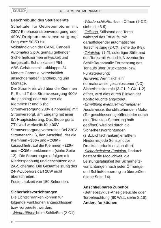
ALLGEMEINE MERKMALE�����
Beschreibung des Steuergeräts
Schalttafel für Getriebemotoren mit230V-Einphasenstromversorgung oder400V-Dreiphasenstromversorgung;Frequenz: 50-60 Hz.Vollständig von der CAME CancelliAutomatici S.p.A. gemäß geltenderSicherheilsnormen entwickelt undhergestellt. Schutzklasse IP54.ABS-Gehäuse mit Luftklappe. 24Monate Garantie, vorbehaltlichunsachgemäßer Handhabung undMontage.Der Stromkreis wird über die KlemmenR, S und T (bei Stromversorgung 400Vdreiphasing) oder nur über dieKlemmen R und S (beiStromversorgung 230V einphasing) mitStromversorgt, am Eingang mit einer8A-Hauptsicherung. Das SteuergerätZT4 wird werkseits für 400VStromversorgung vorbereitet. Bei 230VStromanschluß, den Anschluß, der dieKlemmen «380» und «COM»kurzschließt auf die Klemmen «220»und «COM» umklemmen (siehe Seite12). Die Steuerungen erfolgen mitNiederspannung und geschützen enie2A-Sicherung. Die Gesamtleistung des24-V-Zubehörs darf 20W nichtüberschreiten.Feste Laufzeit von 150 Sekunden.
SicherheitsvorrichtungenDie Lichtschranken können fürfolgende Funktionen angeschlossenbzw. vorbereitet werden:-Wiederöffnen beim Schließen (2-C1);
-Wiederschließen beim Öffnen (2-CX,siehe dip 8-9);-Teilstop, Stillstand des Toreswährend des Torlaufs, mitdarauffolgender automatischerTorschließung (2-CX, siehe dip 8-9);-Totalstop (1-2), sofortiger Stillstanddes Tores mit Ausschluß eventuellerSchließautomatik: Fortsetzung desTorlaufs über Drucktaster- bzw.Funksteuerung;Hinweis: Wenn sich einnormalerweise geschlossener (NC)Sicherheitskontakt (2-C1, 2-CX, 1-2)öffnet, wird dies durch Blinken derKontrolleuchte angezeigt.-Ermittlung eventuell vorhandenerHindernisse. Bei stillstehendem Motor(Tor geschlossen, geöffnet oder durcheine Totalstop-Steuerung halbgeöffnet) wird bei durch dieSicherheitsvorrichtungen(z.B.:Lichtschranken) erfaßtemHindernis jede Sensor-oderDrucktasterfunktion annulliert;-Sicherheitstest-Funktion. Dadurchbesteht die Möglichkeit, dieLeistungsfähigkeit der Sicherheits-vorrichtungen nach jeder Öffnungs-und Schließsteuerung zu überprüfen(siehe Seite 14).
Anschließbares Zubehör-Betriebszyklus-Anzeigeleuchte oderTorbeleuchtung (60 Watt, siehe S.16);Andere funktionen
- 9 -
-Schließautomatik. Der Schließ-automatik-Zeischalter speist sich beimÖffnen am Ende der Torlaufzeit selbst.Die voreingestellte Zeit ist auf jedenFall immer dem Eingriff eventuellerSicherheitsvorrichtungenuntergeordnet und schließt sich nacheinem “Stop”-Eingriff bzw. beiStromausfall selbst aus;-Teilweises Öffnung. Das Öffnen desTors für das Durchlassen vonFußgängern wird durch Anschluß andie Klemmen 2-3P aktiviert und kannüber den Trimmer AP.PARZ. eingestelltwerden. Wenn diese Funktion aktiviertist, variiert das automatischeSchließen folgendermaßen:1)Dip 12 auf ON: Nach einemteilweisen Öffnen erfolgt das Schließendes Tor unabhängig von derEinstellung des Trimmer TCA und derStellung des Dip-Switch 1, und zwarnach einer vorgegebenen Zeit von 8Sekunden;2)Dip 12 auf OFF: Nach einemteilweisen Öffnen kann die Zeit für dasautomatische Schließen nur danneingestellt werden, wenn der Dip-Switch 1 auf ON steht;-Betriebszyklus-Anzeigeleuchte. DasLicht, das den Torbereich beleuchtet,bleibt vom Beginn des Öffnens bis zumvollständigen Schließen der Torflügeleingeschaltet (einschließlich Wartezeitfür automatisches Schließen). Wenndas automatische Schließen nichtzugeschaltet ist, bleibt das Licht nurwährend der Torbewegungeingeschaltet (E-EX),siehe S.16;-Torbeleuchtung. Nachdem der Befehl
zum Öffnen des Tors gegeben wordenist, bleibt das Licht, das den Manöver-bereich am Tor beleuchtet, für einevorgegebene Zeit von 5 Minuten und30 Sekunden eingeschaltet (E-EX),siehe S. 16;-Funktion “Bedienung vom Steuerpult”.Torbetrieb durch Drucktasterbetätigung(Funkfernsteuerung ausgeschlossen);-Vorblinken. Das Licht blinkt sowohl vordem Öffnen als auch vor demSchließen zunächst 5 Sekunden lang;-Master-Funktion (übergeordnet).Wenn zwei Motoren kombiniertwerden, übernimmt die Schalttafel alleSteuerungsfunktionen (siehe S.30);-Slave-Funktion (untergeordnet). DieSchalttafel unterliegt komplett derSteuerung durch die MASTER-Schalttafel (siehe S.30);- Zum Aktivieren der Funktionenteilweiser Stop oder erneutesSchließen während der Öffnungsphase(NC-Kontakt 2-CX) bitte eine derbeiden Funktionen mithilfe vom Dipwählen (siehe Funktionswahl);-Befehlsarten:-Öffnen-Schließen-Inversion für Druck-knopf und Sender;-Öffnen-Stop-Schließen-Stop fürDruckknopf und Sender;-nur Öffnen für Sender.
Einstellungen- Zeit für das automatische Schließen;- Zeit für das teilweise Öffnen.
Achtung! vor Eingriff im Innern
des Gerätes den Netzstecken ziehen.

- 10 -
CARACTERISTICAS GENERALES������
Descripción cuadro de mando
Cuadro eléctrico para motorreductorescon alimentación 230V monofásica o400V trifásica: frecuencia 50÷60 Hz.Diseñado y fabricado enteramente porCAME Cancelli Automatici S.p.A.,cumple con las normas de seguridadvigentes, con grado de protecciónIP54. Caja de ABS, dotada de tomapara la recirculación de aire.Garantizado 24 meses salvomanipulaciones.El circuito se debe alimentar en losbornes R, S y T (con alimentación de400V trifásica) o bien sólo en losbornes R y S (con alimentación de230V monofásica), está protegido enentrada con fusible de línea de 8A. Elcuadro de mando ZT4 viene yadispuesto para la alimentación de400V. Caso de que se alimente con230V, desplazar la conexión quecortocircuita los bornes «380» y«COM» en los bornes «220» y «COM»(vèase pàg.12). Los dispositivos demando son a baja tensión y estàprotegidos por fusible a 2A. Lapotencia total de los accesorios a 24V,no debe superar los 20W.Tiempo de trabajo fijo a 150 segundos.
SeguridadLas fotocélulas pueden estarconectadas y predispuestas para:-Reapertura en la fase de cierre (2-
C1);-Recierre en la fase de apertura (2-CX,ver dip 8-9);-Parada parcial, parada de la puerta sise encuentra en movimiento con laconsiguiente predisposición al cierreautomático (2-CX, ver dip 8-9);-Parada total (1-2), parada de la puertaexcluyendo el posible ciclo de cierreautomático; para reactivar elmovimiento es preciso actuar en elteclado o en el mando a distancia);Nota: La apertura de un contacto deseguridad normalmente cerrado (2-C1,2-CX, 1-2) es señalada por medio deldestello del LED de señalización.-Detección de presencia obstáculo.Con el motor parado (puerta cerrada,abierta o en posición semi-abiertaobtenida a través de un comando destop total), anula cualquier función deltransmisor o del botón en caso deobstáculo detectado por losdispositivos de seguridad (por ejemplo:fotocélulas);-Función de las pruebas de seguridad.Permite a la central comprobar laeficiencia en los dispositivos deseguridad después de cada comandode apertura y cierre (véase pág.14).
Accesorios conectables-Làmpara ciclo o luz de cortesía (60
- 11 -
Watt, véase pág.16);Otras funciones-Cierre automático. El temporizador decierre automático se autoalimenta enfin-de-tiempo carrera en fase deapertura. El tiempo prefijado regulable,sin embargo, está subordinado a laintervención de posibles accesorios deseguridad y se excluye después deuna intervención de parada o en casode falta de energía eléctrica;-Apertura parcial. La apertura de laverja para el paso peatonal, se activaconectando los bornes 2-3P y puedeser regulada por medio del trimmerAP.PARZ. Con dicha función el cierreautomático se modifica de la siguientemanera:1) Dip 12 en ON: luego de una apertu-ra parcial, el tiempo de cierreautomático es independiente de laregulación del trimmer TCA y de laposición del dip 1 y queda fijo en 8segundos;2) Dip 12 en OFF: luego de una aper-tura parcial, el tiempo de cierreautomático puede ser regulado sólo siel dip 1 está colocado en ON;-Lámpara ciclo. Lámpara que alumbrala zona de maniobra: se quedaencendida a partir del momento enque las hojas empiezan la aperturahasta el cierre completo (incluyendo eltiempo de cierre automático). Si no sehabilita el cierre automático, el cierrepermanece encendido sólo durante elmovimiento (E-EX), véase pág.16;-Luz de cortesía. Lámpara que ilumina
la zona de maniobra; tras un mando de
apertura permanece encendida por 5minutos y 30 segundos (E-EX), véasepág.16;-Función a "hombre presente". Fun-cionamiento de la puerta manteniendopulsada la tecla (excluye la función delmando a distancia);-Intermitencia previa de 5 segundostanto en el momento de apertura comode cierre de la puerta;-Función master; el cuadro asumetodas las funciones de mando en elcaso de dos motores combinados(véase página 30);-Función slave; el cuadro es accionadoexclusivamente por el “MASTER”(véase página 30);- Habilitación para las funciones deparada parcial o cierre durante la aper-tura, contacto normalmente cerrado (2-CX), seleccionar una de las dosfunciones mediante Dip (ver selecciónde las funciones);-Tipo de mando:-abrir-cerrar-inversión para botón ytransmisor;-abrir-stop-cerrar-stop para botón ytransmisor;-sólo apertura para transmisor.
Regulaciones- Tiempo de cierre automático;- Tiempo de apertura parcial.
¡Atención! Antes de actuar den-
tro del aparato, quitar la tensión de
línea.
- 12 -
���
������ �������
AF
ZT4
21 3 4 5 6 7 8 9 10
ON
1211 13 14 15 16 17 18 19 20
ON
��
�� ���������
�� ������
���� �����
SCHEDA BASE - MOTHERBOARD - CARTE BASE - GRUNDPLATINE - TARJETA BASE
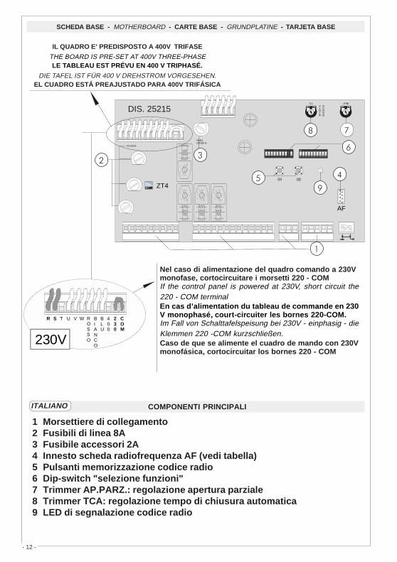
Nel caso di alimentazione del quadro comando a 230Vmonofase, cortocircuitare i morsetti 220 - COMIf the control panel is powered at 230V, short circuit the220 - COM terminalEn cas d’alimentation du tableau de commande en 230V monophasé, court-circuiter les bornes 220-COM.Im Fall von Schalttafelspeisung bei 230V - einphasig - dieKlemmen 220 -COM kurzschließen.Caso de que se alimente el cuadro de mando con 230Vmonofásica, cortocircuitar los bornes 220 - COM
DIS. 25215
COMPONENTI PRINCIPALI
1 Morsettiere di collegamento2 Fusibili di linea 8A3 Fusibile accessori 2A4 Innesto scheda radiofrequenza AF (vedi tabella)5 Pulsanti memorizzazione codice radio6 Dip-switch "selezione funzioni"7 Trimmer AP.PARZ.: regolazione apertura parziale8 Trimmer TCA: regolazione tempo di chiusura automatica9 LED di segnalazione codice radio
ITALIANO
�
�
�
�
�
�
�
�
R S T U V W ROSSO
BIANCO
BLU
400
230
COM
230V
IL QUADRO E’ PREDISPOSTO A 400V TRIFASE
THE BOARD IS PRE-SET AT 400V THREE-PHASELE TABLEAU EST PRÉVU EN 400 V TRIPHASÉ.
DIE TAFEL IST FÜR 400 V DREHSTROM VORGESEHEN.EL CUADRO ESTÁ PREAJUSTADO PARA 400V TRIFÁSICA

- 13 -
MAIN COMPONENTS
1 Terminal block for external connections2 8A line fuse3 2A accessories fuse4 Socket AF radiofrequency board (see table)5 Radio-code save buttons6 "Function selection" Dip-switch7 Trimmer AP.PARZ.: Partial opening adjustment8 Trimmer TCA: automatic closing time adjustment9 Radio-code LED
COMPOSANTS PRINCIPAUX
1 Plaque à bornes pour les branchements2 Fusibles de ligne 8A3 Fusible accessoires 2A4 Branchement carte radiofréquence AF (voir tableau)5 Boutons mise en mémoire code radio et programmation6 Dip-switch "sélection fonction"7 Trimmer AP.PARZ.: réglage ouverture partielle8 Trimmer TCA: réglage temps de fermeture automatique9 LED de segnalisation code radio
HAUPTKOMPONENTEN
1 Anschluss-Klemmenleiste2 8A-Sicherung Leitungs3 2A-Sicherung Zubehörs4 Steckanschluß Funkfrequenze-Platine AF (sehen Tabelle)5 Knöpfe zum Abspeichern der Radiocodes6 "Funktionswahl" Dip-switch7 Trimmer AP.PARZ.: Einstellung Teilöffnung8 Trimmer TCA: Einstellung Zeiteinstellung Schließautomatik9 LED Kontrolleuchte zur Anzeige von Radiocode
COMPONENTES PRINCIPALES
1 Caja de bornes para las conexiónes2 Fusibles de línea 8A3 Fusible accesorios 2A4 Conexión tarjeta radiofrecuencia AF (vedas tabla)5 Botones de memorización del código radio6 Dip-switch "seleción función"7 Trimmer AP.PARZ.: regulación apertura parcial8 Trimmer TCA: regulación cierre automático9 Indicador luminoso código radio
DEUTSCH
ESPANOL
ENGLISH
FRANÇAIS
- 14 -
E4 10 11 TS 1 2 3 3P 4 5 6 7 2MOT
N
.O.
N
.C.
C
.
+ - + -
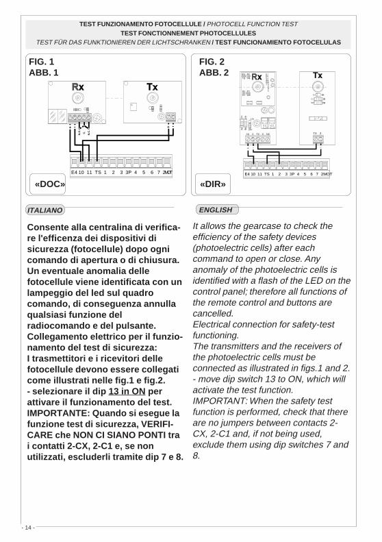
Consente alla centralina di verifica-re l'efficenza dei dispositivi disicurezza (fotocellule) dopo ognicomando di apertura o di chiusura.Un eventuale anomalia dellefotocellule viene identificata con unlampeggio del led sul quadrocomando, di conseguenza annullaqualsiasi funzione delradiocomando e del pulsante.Collegamento elettrico per il funzio-namento del test di sicurezza:I trasmettitori e i ricevitori dellefotocellule devono essere collegaticome illustrati nelle fig.1 e fig.2.- selezionare il dip 13 in ON perattivare il funzionamento del test.IMPORTANTE: Quando si esegue lafunzione test di sicurezza, VERIFI-CARE che NON CI SIANO PONTI trai contatti 2-CX, 2-C1 e, se nonutilizzati, escluderli tramite dip 7 e 8.
TEST FUNZIONAMENTO FOTOCELLULE / PHOTOCELL FUNCTION TESTTEST FONCTIONNEMENT PHOTOCELLULES
TEST FÜR DAS FUNKTIONIEREN DER LICHTSCHRANKEN / TEST FUNCIONAMIENTO FOTOCELULAS
ENGLISHITALIANO
E4 10 11 TS 1 2 3 3P 4 5 6 7 2MOT
10 2 TX C NC
24V
12V
FUSIBILE 200mA
TX 2TX 2
� � �
FIG. 2ABB. 2
«DIR»
FIG. 1ABB. 1
«DOC»
It allows the gearcase to check theefficiency of the safety devices(photoelectric cells) after eachcommand to open or close. Anyanomaly of the photoelectric cells isidentified with a flash of the LED on thecontrol panel; therefore all functions ofthe remote control and buttons arecancelled.Electrical connection for safety-testfunctioning.The transmitters and the receivers ofthe photoelectric cells must beconnected as illustrated in figs.1 and 2.- move dip switch 13 to ON, which willactivate the test function.IMPORTANT: When the safety testfunction is performed, check that thereare no jumpers between contacts 2-CX, 2-C1 and, if not being used,exclude them using dip switches 7 and8.

- 15 -
FRANÇAIS DEUTSCH
ESPANOL
Il permet à la centrale de vérifierl'efficacité des dispositifs desécurité (photocellules) aprèschaque commande d'ouverture oude fermeture. Un led qui clignote surle tableau de commande indique uneanomalie éventuelle desphotocellules, ce qui annule toutefonction de la radiocommande etdes boutons.Branchement électrique pour lefonctionnement du test de sécurité.Les émetteurs et les récepteurs desphotocellules doivent être branchéscomme indiqué sur les fig. 1 et 2.- mettre le dip-switch 13 sur ONpour activer le fonctionnement dutest.IMPORTANT: En effectuant lafonction test de sécurité, VERIFIERs'il Y A DES PONTS entre lescontacts 2-CX, 2-C1 et les exclure àl'aide des microinterrupteurs 7 et 8,s'ils ne sont pas utilisés.
Erlaubt der Steuerung, dieFunktionstüchtigkeit derSicherheitsvorrichtungen(Lichtschranken) nach jedem Befehlzum Öffnen oder Schließen zukontrollieren. Eine Störung an denLichtschranken wird durch Blinken vomLED an der Steuertafel angezeigt undsetzt Fernbedienung und Tastenvorübergehend außer Betrieb.Stromanschluß für den Sicherheitstest.Die Sender und Empfänger derLichtschranken müssen wie auf Abb. 1und 2 dargestellt angeschlossenwerden.BITTE BEACHTEN: Wenn derSicherheitstest durchgeführt wird, mußSICHERGESTELLT werden, daß dieKontakte 2-CX und 2-C1 nicht.- Dip-Switch 13 zur Aktivierung derSicherheitstest-Funktion auf ONstellen.ÜBERBRÜCKT sind. Wenn dieKontakte nicht benützt werden, müssensie mit den Dip-Schaltern 7 und 8ausgeschlossen werden.
Permite que la central verifique la eficiencia de los dispositivos deseguridad (fotocélulas) después de cada mando de apertura o de cierre.Una posible irregularidad de las fotocélulas es identificada con unparpadeo del indicador luminoso en el cuadro de mandos, anulando todafunción de los radiomandos y de los botones.Conexión eléctrica para el funcionamiento del ensayo de seguridad.Los transmisores y receptores de las fotocélulas se deben conectar talcomo muestran las figuras 1 y 2.- seleccionar el dip 13 en ON para activar el funcionamiento de la prueba.IMPORTANTE: cuando se ejecuta la función de ensayo de seguridad,CONTROLE que NO HAYA PUENTES DE CONEXIÓN entre los contactos 2-CX, 2-C1 y, si no se los utiliza, desconéctelos con los dips 7 y 8.

- 16 -
COLLEGAMENTI ELETTRICI - ELECTRICAL CONNECTIONS - BRANCHEMENTS ÉLECTRIQUES ELEKRISCHE ANSCHLÜSSE - CONEXIONES ELÉCTRICAS
�
�
�
�
�
�
�
�
�
R S T U V W E E1 EX E4 10 11 TS 1 2 3 3P 4 5 6 7 2MOT FC FA F 2 C1 CX B1 B2
Alimentazione 230V (a.c.) monofase (220-COM)230V (a.c.) power input single-phase (220-COM)Alimentation 230V (c.a.) monophasée (220-COM)Stromversorgung 230V (Wechselstrom) einphaseing (220-COM)Alimentación 230V (a.c.) monofásica (220 -COM)
Alimentazione 400V (a.c.) trifase (380-COM)400V (a.c.) power input three-phase (380-COM)Alimentation 400V (c.a.) triphasée (380-COM)Stromversorgung 400V (Wechselstrom) dreiphaseing (380-COM)Alimentación 400V (a.c.) trifásica (380 -COM)
Motore monofase/trifase 230/400V (a.c.)230/400V (a.c.) single-phase/three-phase motorMoteur monophasé/triphasée 230/400V (c.a.)Motor einphasen/dreiphasen 230/400V (Wechselstrom)Motor monofàsico/trifásico 230/400V (a.c.)
Uscita 230V (a.c.) in movimento(es.lampeggiatore - max. 25W)230V (a.c.) output in motion(e.g. flashing light - max. 25W)Sortie 230V (c.a.) en mouvement(ex. branchement clignotant - max. 25W)Ausgang 230V (Wechselstrom) in Bewegung(z.B. Blinker-Anschluß - max. 25W)Salida de 230V (a.c.) en movimento(p.ej. conexión lámpara intermitente - max. 25W)
Lampada ciclo (230V)o cortesia (230V)(230V) cycle lamp or (230V)courtesy lightLampe cycle (230V)ou lampe passage (230V)Betriebszyklus-Anzeigeleuchteoder Torbeleuchtung (230V)Lámpara ciclo (230V)o luz de cortesía (230V)
1211 13 14 15 16 17 18 19 20ON
���������������COURTESY LIGHT�����������
TORBELEUCHTUNG�������������(16 ON - 17 OFF)
��������������
�������������CYCLE LAMP���������
BETRIEBSZYKLUS-ANZEIGELEUCHTE�������������(17 ON - 16 OFF)
MAX. WATT60

- 17 -
��
��
��
��
��
��
���
���
�
��
��
��
Alimentazione accessori 24V (a.c.) max. 20W24V (a.c.)Powering accessories (max 20W)Alimentation accessoires 24V (c.a.) max. 20WZubehörspeisung 24V (Wechselstrom) max. 20WAlimentación accesoios 24V (a.c.) max. 20W
Pulsante stop (N.C.)Pushbutton stop (N.C.)Bouton-poussoir arrêt (N.F.)Stop-Taste (N.C.)Pulsador de stop (N.C.)
Pulsante apre (N.O.)Pushbutton opens (N.O.)Bouton-possoir ouverture (N.O.)Taste Öffnen (Arbeitskontakt)Pulsador de apertura (N.O.)
Pulsante per apertura parziale (N.O.)Open button (N.O.) for partial openingBouton-poussoir d'ouverture (N.O.) pour ouverture partialTaste Öffnen (Arbeitskontakt) für TeilÖffnungPulsador de apertura (N.O.) para aperture parcial
Lampada spia (24V-3W max.) "cancello aperto"(24V-3W max.) "gate-opened" signal lampLampe-témoin (24V-3W max.) "portail ouverture"Signallampe (24V-3W max.) "Tor Öffnen"Lampada indicadora (24V-3W max.) "puerta abierto"
Lampada spia (24V-3W max.) "cancello chiuso"(24V-3W max.) "gate-closed" signal lampLampe-témoin (24V-3W max.) "portail fermeture"Signallampe (24V-3W max.) "Tor Schließen"Lampada indicadora (24V-3W max.) "puerta cierre"
Uscita 24V (a.c.) in movimento24V (a.c.) output in motionSortie 24V (c.a.) en mouvementAusgang 24V (Wechselstrom) in BewegungSalida de 24V (a.c.) en movimento
Pulsante di chiusura (N.O.)Close pushbutton (N.O.)Bouton-poussoir de fermeture (N.O.)Taste Schließen (Arbeitskontakt)Pulsador de cierre (N.O.)
��
�
��
��

- 18 -
�����
��
��
��
��
��
��
Contatto radio e/o pulsante per comando (vedi dip-switch2-3 sel.funzioni)Contact radio and/or button for control (see dip-switch 2-3function selection)Contact radio et/ou poussoir pour commande (dip-switch2-3 sel.fonction)Funkkontakt und/oder Taste Steuerart (dip-switch 2-3Funktionswahl)Contacto radio y/o pulsador para mando (dip-switch 2-3seleción fonción)
Contatto (N.C.) di «riapertura durante la chiusura»Contact (N.C.) for «re-opening during the closing»Contact (N.F.) de «réouverture pendant la fermeture»Kontakt (Ruhekontakt) «Wiederöffnen beim Schliessen»Contacto (N.C.) para la «apertura en la fase de cierre»
Contatto (N.C.) «richiusura durante la apertura»Contact (N.C.) «re-closing during the opening»Contact (N.F.) «réfermeture pendant la ouverture»Kontakt (Ruhe.) «Wiederschliessen beim Öffnen»Contacto (N.C.) «apertura en la fase de cierre»
Contatto (N.C.) stop parzialePartial stop contact N.C.Contact (N.F.) d'arrêt partialTeil-Stop (Ruhekontakt) KontaktContacto (N.C.) de stop parcia
Collegamento antennaAntenna connectionConnexion antenneAntennenanschlußConexión antena
Uscita contatto (N.O.) Portata contatto: 5A a 24V (d.c.)Contact output (N.O.) Resistive load: 5A 24V (d.c.)Sortie contact (N.O.) Portée contact: 5A a 24V (c.c.)Ausgang Arbeitskontakt Stromfestigkeit: 5A bei 24V(Gleichstrom)Salida contacto (N.O.) Carga resistiva: 5A a 24V (d.c.)
Uscita per comando di n.2 motori abbinatiConnection for simultaneous control of 2 combined motorsSortie pour commande simultanée de 2 moteurs accouplesAusgang zur gleichzeitigen Steuerung von 2 parallelgeschaltetenMotorenSalida para el mando simultáneo de n.2 motores acoplados
��
��
8 OFF - 9 OFF8 OFF - 9 OFF8 OFF - 9 OFF8 OFF - 9 OFF8 OFF - 9 OFF
8 OFF - 9 ON8 OFF - 9 ON8 OFF - 9 ON8 OFF - 9 ON8 OFF - 9 ON
� � � � � � � � �
ON
� � � � � � � � �
ON

- 19 -
FUS.LINEA 5A
EN
CO
DE
R
FUSIBILEACCESSORI 2A
T.C.A. AP.PA RZ.
Collegamento finecorsa apreConnection limit switch opensConnexion fin de course ouvertureAnschluß Endschallter ÖffnungConexión fin de carrera apertura
Collegamento finecorsa chiudeConnection limit switch closesConnexion fin de course fermetureAnschluß Endschallter SchließungConexión fin de carrera cierre
�
�
�
�
REGOLAZIONI - ADJUSTMENTS - RÉGLAGES - EINSTELLUNGEN - REGULACIONES
ITALIANO
FRANÇAISENGLISH
ESPANOLDEUTSCH
������������ ���
���������������
����������� ���
������ �������
�������������� ���
Trimmer T.C.A. = Regolazione tempodi chiusura automatica da un minimodi 1 secondo a un massimo di 150 sec.Trimmer AP.PARZ. = Regolazione diapertura parziale da un minimo di 1secondo a un massimo di 14 secondi.
Trimmer T.C.A. = Regulación deltiempo de cierre automático, desdeun mínimo de 1 segundo hasta unmáximo de 150 segundos.Trimmer AP.PARZ. = Regulación deapertura parcial, desde un mínimo de1 segundo hasta un máximo de 14segundos.
Trimmer T.C.A. = Réglage du tempsde fermeture automatique d'unminimum de 1 seconde à un maximunde 150 sec.Trimmer AP.PARZ. = Réglage d'ou-verture partial d'un minimum de 1seconde à un maximun de 14secondes.
Trimmer T.C.A. = Adjusts automaticclosing time from a minimum of 1 secondto a maximum of 150 seconds.Trimmer AP.PARZ. = Adjusts partialopening from a minimum of 1 second toa maximum of 14 seconds.
Trimmer T.C.A. = Timer, auf dem dieVerzögerung für das automatischeSchließen mit mindestens 1 Sekund undhöchstens 150 Sekunden eingestelltwerden kann.Trimmer AP.PARZ. = Timer, auf demdie Verzögerung für das Teilöffnung mitmindestens 1 Sekund und höchstens 14Sekunden eingestellt werden kann.
T.C.A. AP.PARZ.

- 20 -
FUS.LINEA 5A
EN
CO
DE
R
FUSIBILEACCESSORI 2A
T.C.A. AP.PA RZ.
SELEZIONI FUNZIONI - SELECTION OF FUNCTIONS - SÉLECTION FONCTIONSFUNKTIONSWAHL- SELECCIÓN DE LAS FUNCIONES
DIP-SWITCHES (1-10)
��������
1 ON - Funzione chiusura automatica attivata; (1OFF-disattivata)2 ON - Funzione "apre-stop-chiude-stop" con pulsante (2-7) e radio comando
(scheda AF inserita) attivato;2 OFF- Funzione "apre-chiude" con pulsante (2-7) e radiocomando (scheda
AF inserita) attivato;3 ON - Funzione "solo apertura" con radiocomando (scheda AF inserita)
attivato; (3OFF-disattivato)4 ON - Funzione a "uomo presente" (esclude la funzione del radiocomando)
attivato; (4OFF-disattivato)5 ON - Prelampeggio in apertura e chiusura attivato; (5OFF-disattivato)6 ON - Funzione rilevazione ostacolo attivato; (6OFF-disattivata)7 OFF- Funzione di riapertura in fase di chiusura (collegare il dispositivo di
sicurezza sui morsetti 2-C1) attivata; (7ON-disattivata)8OFF/9OFF - Funzione di richiusura in fase di apertura (collegare il disposi-
tivo di sicurezza sui morsetti 2-CX) attivata;8OFF/9ON - Funzione di stop parziale (collegare il dispositivo di sicurezza
sui morsetti 2-CX) attivato;(se non vengono utilizzati i dispositivi su 2-CX, posizionare il dip 8 in ON)10OFF -Funzione di stop totale (collegare pulsante su 1-2) attivato; (10ON -
disattivato)
� � � � � � � � �
ON
� � � � � � � � � � � � � � � � � �
ON

- 21 -
1 ON - Function automatic closure enabled; (1OFF-disabled)2 ON - "open-stop-close-stop" function with button (2-7) and radio control (AF board
inserted) enabled;2 OFF- "open-close" function with button (2-7) and radio control (AF board inserted)
enabled;3 ON - "only opening" function with radio control (AF board inserted) enabled;4 ON - "Operator present" operation (radio remote control is deactivated when
function is selected) enabled; (4OFF-disabled)5 ON - Pre-flashing (opening and closing) enabled; (5OFF-disabled)6 ON - Function obstacle detection device enabled; (6OFF-disabled)7 OFF- Function re-opening in closing phase (connect the safety device on terminals
2-C1) enabled; (7ON-disabled)8OFF/9OFF - Function of re-closing while opening (connect the safety device on
terminals 2-CX) enabled;8OFF/9ON - Partial stop function (connect the safety device on terminals 2-CX)
enabled;(if the devices on the 2-CX terminals are not used, set Dip 8 to ON)10OFF -Total stop function (connect the button onto terminals 1-2) enabled
�����
FRANÇAIS
1 ON - Fonction fermeture automatique activé; (1OFF- éteinte)2 ON - Fonction "ouvre-stop-ferme-stop" avec bouton (2-7) et commande-
radio (carte AF insérée) activé;2 OFF- Fonction "ouvre-ferme" avec bouton (2-7) et commande-radio (carte
AF insérée) activé;3 ON - Fonction "soulement ouverture" avec commande-radio (carte AF
insérée) mise en route;4 ON - Fonctionnement avec "homme mort" (exclut la fonction
radiocommande) activé; (4OFF-éteinte)5 ON - Preclignotement pandant la phase d'ouverture et de fermeture activé;
(5OFF-éteinte)6 ON - Fonction dispositif de détection d'obstacle activé;(6OFF - éteinte)7 OFF- Fonction réouverture en phase de fermeture (relier le dispositif de
sécuritè aux bornes 2-C1) activé; (7ON-éteinte)8OFF/9OFF -Fonction de réfermeture en phase d'ouverture (relier le dispositif
de sécuritè aux bornes 2-CX) activé;8OFF/9ON -Fonction de stop partiel (relier le dispositif de sécuritè aux
bornes 2-CX) activé;(si les dispositifs sur 2-CX ne sont pas utilisés, positionner le dip 8 sur ON)10OFF -Fonction de stop total (relier le bouton sur les bornes 1-2) activé

- 22 -
ESPANIOL
1 ON - Funktion Schließautomatik zugeschaltet; (1OFF- ausgeschlo.)2 ON - Funktion "Öffnen-Stop-Schließen-Stop" mit Druckknopf (2-7) und
Fernsteuerung (Karte AF eingesteckt) zugeschaltet;2 OFF- Funktion "Öffnen-Schließen" mit Druckknopf (2-7) und Fernsteuerung (Karte
AF eingesteckt) zugeschaltet;3 ON - Funktion "nur Öffnen" mit Fernsteuerung (Karte AF eingesteckt) zugeschaltet;4 ON - Bedienung vom "Steuerpult" (bei Wahl dieser Betriebsart wird die
Funkfernsteuerung ausgeschlossen) zug.; (4OFF-ausg.)5 ON - Vorblinken beim Öffnen und Schließen zuges;(5OFF-ausg.)6 ON - Funktion Hindemisaufnahme zugeschaltet;(6OFF ausges.)7 OFF- Wiederöffnen beim Schließen zugeschaltet (schließen Sie die
Sicherheitsvorrichtung an die Klemmen 2-C1 an) zugeschaltet; (7ON-ausgeschlossen)
8OFF/9OFF -Funktion für erneutes Schließen während dem Öffnen zugeschaltet(schließen Sie die Sicherheitsvorrichtung an die Klemmen 2-CX an)
8OFF/9ON-Funktion für teilstop zugeschaltet (schließen Sie die Sicherheitsvorrichtungan die Klemmen 2-CX an)
(Wenn die Sicherungen nicht an die Klemmen 2-CX angeschlossen werden, die Dip8 auf ON stellen)
10OFF -Funktion vollständiger Stop (den Druckknopf an die Klemmen 1-2 anschließen)
1 ON - Función cierre automático activado; (1OFF-desactivado)2 ON - Función "abrir-stop-cerrar-stop" con botón (2-7) y radiocontrol (tarjeta
AF conectada) activ.;2 OFF- Función "abrir-cerrar" con botón (2-7) y radiocontrol (tarjeta AF
conectada) activado;3 ON - Función "solo apertura" con radiocontrol (tarjeta AF conectada) activado;4 ON - Funcionamiento a "hombre presente" (escluye la función del mando de
radio) activado; (4OFF-desactivado.)5 ON - Pre-intermitencia en la fase de apertura y cierre activado; (5OFF-
desactivado.)6 ON - Función de detección del obstáculo activado; (6OFF-des.)7 OFF Función de reapertura en la fase de cierre (conecte el dispositivo de
seguridad a los bornes 2-C1) activado; (7ON-desactivado.)8OFF/9OFF Función de recierre durante la apertura (conecte el dispositivo
de seguridad a los bornes 2-CX) activado;8OFF/9ONFunción de parada parcial (conecte el dispositivo de seguridad a los
bornes 2-CX) activ.;(si no utiliza los dispositivos en 2-CX, coloque el dip 8 en ON)10OFF -Función de parada total (conecte el botón a los bornes 1-2) activado
DEUTSCH

- 23 -
FUS.LINEA 5A
EN
CO
DE
R
FUSIBILEACCESSORI 2A
T.C.A. AP.PA RZ.
DIP-SWITCHES (11-20)
11 OFF - Funzione "slave" disattivata (da attivare nel caso di collegamento
abbinato, pag.30)
12 ON - Funzione di apertura parziale (la chiusura automatica è fissa a 8")
attivata;
12 OFF- Funzione di apertura parziale (la chiusura automatica è regolabile
mediante trimmer, se inserita) attivata;
13 ON - Funzione del test di sicurezza per la verifica dell'efficenza delle
fotocellule (vedi pag.14) attivato; (13 OFF disattivato)
14 OFF - Funzione "master" disattivata (da attivare nel caso di collegamento
abbinato, pag.30);
15 - Non utilizzato, tenere il dip in posizione «OFF»
16 ON - Funzione lampada di cortesia attivata; (16 OFF-disattivata)
17 ON - Funzione lampada ciclo attivata; (17 OFF-disattivata)
18 - Non connesso
19 - Non connesso
20 - Non connesso
�TALIANO
� � � � � � � � � � � � � � � � � � � � � � � � � � �
ON ON

- 24 -
ENGLISH
11OFF - "Slave" function disabled (to activate only for coupled connection, see
p.30)
12ON - Partial opening function (automatic closing is fixed at 8 seconds) enabled;12OFF - Partial opening function (automatic closing is adjusted with the trimmer, if
inserted) enabled;13ON - Activates safety test that checks the photocells proper operation (see
pag.14) enabled; (13OFF-disabled)14OFF - "Master" function disabled (to activate only for coupled connection, see
p.30)
15 - Not used, keep the dip in position "OFF"
16ON - Courtesy light function enabled; (16OFF-disabled)17ON - Lamp cycle function enabled; (17OFF-disabled)18 - Not connected
19 - Not connected
20 - Not connected
11OFF - Fonction "slave" désactivée (à n'activer que pour le branchement
accouplé, voir page 30);
12ON - Fonction d'ouverture partielle (la fermeture automatique est fixe à 8")
activé
12OFF - Fonction d'ouverture partielle (la fermeture automatique est réglable
au moyen du trimmer, si elle est enclenchée) activé;
13ON - Activation du test de sécurité pour le contrôle du bon fonctionnement
des photocellules (voir pag.14) activé; (13OFF-désactivée)
14OFF - Fonction "master" désactivée (à n'activer que pour le branchement
accouplé, voir page 30);
15 - Pas utilisé, garder le commutateur à bascule sur "OFF"
16ON - Fonction lampe d'éclairage activé;(16OFF-désactivée )
17ON - Fonction lampe cycle activé;(17OFF-désactivée )
18 - Non connecté
19 - Non connecté
20 - Non connecté
FRANÇAIS
- 25 -
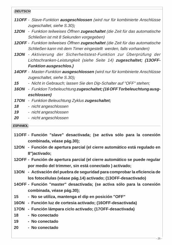
11OFF - Slave-Funktion ausgeschlossen (wird nur für kombinierte Anschlüssezugeschaltet, siehe S.30);
12ON - Funktion teilweises Öffnen zugeschaltet (die Zeit für das automatischeSchließen ist mit 8 Sekunden vorgegeben)
12OFF - Funktion teilweises Öffnen zugeschaltet (die Zeit für das automatischeSchließen kann mit dem Timer eingestellt werden, falls vorhanden)
13ON - Aktivierung der Sicherheitstest-Funktion zur Überprüfung derLichtschranken-Leistungkeit (siehe Seite 14) zugeschaltet; (13OFF-Funktion ausgeschlos.)
14OFF - Master-Funktion ausgeschlossen (wird nur für kombinierte Anschlüssezugeschaltet, siehe S.30);
15 - Nicht in Gebrauch; lassen Sie den Dip-Schalter auf "OFF" stehen;16ON - Funktion Torbeleuchtung zugeschaltet; (16 OFF Torbeleuchtung ausg-
eschlossen)17ON - Funktion Beleuchtung Zyklus zugeschaltet;18 - nicht angeschlossen19 - nicht angeschlossen20 - nicht angeschlossen
DEUTSCH
11OFF - Función "slave" desactivada; (se activa sólo para la conexión
combinada, véase pág.30);
12ON - Función de apertura parcial (el cierre automático está regulado en
8")activado;
12OFF - Función de apertura parcial (el cierre automático se puede regular
por medio del trimmer, sin está conectado ) activado;
13ON - Activación del puebra de seguridad para comprobar la eficiencia de
los fotocélulas (véase pág.14) activado; (13OFF-desactivado)
14OFF - Función "master" desactivada; (se activa sólo para la conexión
combinada, véase pág.30);
15 - No se utiliza, mantenga el dip en posición "OFF"
16ON - Función luz de cortesia activado; (16OFF-desactivada)
17ON - Función lámpara ciclo activado; (17OFF-desactivada)
18 - No conectado
19 - No conectado
20 - No conectado
ESPANIOL
- 26 -
AF
4 "SLAVE"
��
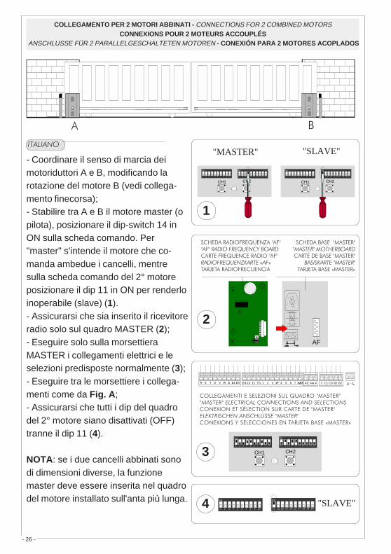
COLLEGAMENTO PER 2 MOTORI ABBINATI - CONNECTIONS FOR 2 COMBINED MOTORSCONNEXIONS POUR 2 MOTEURS ACCOUPLÉS
ANSCHLUSSE FÜR 2 PARALLELGESCHALTETEN MOTOREN - CONEXIÓN PARA 2 MOTORES ACOPLADOS
- Coordinare il senso di marcia deimotoriduttori A e B, modificando larotazione del motore B (vedi collega-mento finecorsa);- Stabilire tra A e B il motore master (opilota), posizionare il dip-switch 14 inON sulla scheda comando. Per"master" s'intende il motore che co-manda ambedue i cancelli, mentresulla scheda comando del 2° motoreposizionare il dip 11 in ON per renderloinoperabile (slave) (1).- Assicurarsi che sia inserito il ricevitoreradio solo sul quadro MASTER (2);- Eseguire solo sulla morsettieraMASTER i collegamenti elettrici e leselezioni predisposte normalmente (3);- Eseguire tra le morsettiere i collega-menti come da Fig. A;- Assicurarsi che tutti i dip del quadrodel 2° motore siano disattivati (OFF)tranne il dip 11 (4).
NOTA: se i due cancelli abbinati sonodi dimensioni diverse, la funzionemaster deve essere inserita nel quadrodel motore installato sull'anta più lunga.
��������
CAMECAME
"MASTER" "SLAVE"
1
��!��������"�����"����������������������������"�����"
��� ������������������#�������$�����%
��!�������� �&�'���"� "�������� �������������������� �&�'��������"� "��� ���������������������#�������� ���'���
2
R S T U V W E E1 EX E4 10 11 TS 1 2 3 3P 4 5 6 7 2MOT FC FA F 2 C1 CX B1 B2
�������'���������'������&������"�����"��������������� ���������� ������������� ����'���'����(�����'������������"�����"������ �������������������������'���'����������'��'����#�������$�����%
3
CH2CH1
21 3 4 5 6 7 8 9 1 0
O N
1 21 1 1 3 1 4 1 5 1 6 1 7 1 8 1 9 2 0
O N
CH2CH1
21 3 4 5 6 7 8 9 1 0
O N
1 21 1 1 3 1 4 1 5 1 6 1 7 1 8 1 9 2 0
O N
1211 13 14 15 16 17 18 19 20
O N
21 3 4 5 6 7 8 9 10
O N
CH2CH1
21 3 4 5 6 7 8 9 1 0
O N
1 21 1 1 3 1 4 1 5 1 6 1 7 1 8 1 9 2 0
O N

- 27 -
���� ��
- Coordonnerle le sens de marche desmotoreducteurs A et B en modifiantlesens de rotation du moteur B (voir finde course);- Fixer entre A et B le moteur master(ou pilote) en positionnant le dip-switch14 sur ON sur la fiche commande. Par“master” il s’agit du moteur qui com-mande les deux grilles, tandis que surla fiche de commande du 2sd moteurpositionner le dip 11 sur ON pour qu’ilsoit piloté "slave" (1).- S'assurer que tous les récepteur radioest bien introduit seulement sur lepupitre MASTER (2);- Effecteur seulement sur la barrette deconnexion MASTER les liaisonsélectriques et les sélectionsnormalment prédisposées (3);- Effectuer les branchements entre lesplaques à bornes de la façon indiquéesur la Fig. A;- S'assurer que tous les dip du pupitredu 2sd moteur sont éteints (OFF) àl'exception du dip 11 (4).
NOTE: Si les deux grilles accoupléesont une dimension différente, lafonction maîtresse doit être prévuedans le tableau du moteur installé surla porte la plus longue.
�����
- Match the directions in which gearmotors A and B rotate by changing thedirection in which motor B rotates (seelimit switch);- Set the master (or pilot) motorbetween A and B by setting dip-switch14 to ON on the control board."Master" refers to the motor thatcontrols both the gates. On the controlboard of the 2nd motor, set dip-switch11 to ON to make it the "slave" (1).- Make sure that the radio receiver isactivated only on the MASTER board(2);- Wire the electrical connections andthe normally used selections only onthe MASTER terminal board (3);- Wire the electrical connectionsbetween the terminal boards, asshown in the Fig. A;- Make sure that all the dip-switcheson the board of the 2nd motor are(OFF), except for dip 11 (4).
NB: If the two coupled gates are ofdifferent sizes, the master functionmust be fitted to the motor controlboard installed on the longer door.
Morsettiera 2° motoreMotor 2° terminal block
Plaque à bornes du 2° moteurKlemmbrett 2° Motor
Cuadro de bornes 2° motor
Morsettiera motore masterMaster motor terminal block
Plaque à bornes du moteur masterKlemmbrett Mastermotor
Cuadro de bornes motor master
��)�����)��
"MASTER" "SLAVE"
E4 10 11 TS 1 2 3 3P 4 5 6 7 2MOT E4 10 11 TS 1 2 3 3P 4 5 6 7 2MOT

- 28 -
- Die Gangrichtung derGetriebemotoren A und B durchDrehrichtungsõnderung des Motores B(siehe Endschalter) koordinieren;- Legen Sie fest, welcher der Motoren Aund B der Master-Motor (übergeordnet)sein soll. Stellen Sie dazu den Dip-Switch 14 auf der Steuerungskarte aufON. Unter Master-Motor wird der Motorverstanden, der beide Tore steuert. Aufder Steuerungskarte des anderenMotors muß der Dip-Switch 11 auf ONgestellt werden, so daß er eineuntergeordnete Funktion (Slave-Motor)bekommt (1).- Kontrollieren Sie, daß derRadioempfänger nur auf der MASTER-Schalttafel eingesteckt ist (2);- Führen Sie nur am MASTERKlemmbrett die elektrischenAnschlüsse und die normalerweisedurchgeführten Voreinstellungen aus(3);- Die Verbindungen zwischen denbeiden Klemmleisten der Abb. Aentsprechend ausführen;- Kontrollieren Sie, daß alle Dip-Switchauf der Schalttafel des untergeordnetenMotor auf OFF stehen, mit Ausnahmevom Dip 11, der auf ON stehen muß(4).
HINWEIS: Wenn die beiden gekoppeltenTore unterschiedlich graß sind, muß dieMaster-Funktion in die Schalttafel derMotors eingesetzt werden, der amlängeren Tor installiert ist.
�������
- Coordinar el sentido de marcha de los
motorreductores A y B, modificando la
rotación del motor B (ver final de
carrera);
- Establezca el motor master (o piloto)
entre los motores A y B, colocando el
dip-switch 14 en ON en la tarjeta de
mando. “Master” significa que el motor
acciona ambas puertas. En la tarjeta
de mando del 2° motor, coloque el dip
11 en ON para que pueda ser
controlado "slave" (1).
- Cerciórese de que el radiorreceptor
esté conectado sólo en el cuadro
MASTER (2);
- Realice las conexiones eléctricas y
las selecciones normalmente
reguladas, sólo en el tablero de bornes
MASTER (3);
- Efectuar entre las cajas de bornes las
conexions como indicado en la Fig. A;
- Cerciórese de que todos los dip del
cuadro del 2° motor estén
desactivados (OFF), excepto el dip 11
(4).
NOTA: Si las dos verjas asociadas
tienen distintos tamaño, la función
master se tiene que conectar en el
cuadro del motor instalado en la hoja
más larga.
�����

- 29 -
ENGLISH
PROCEDURE
A. insert an
AF card **.
B. encodetransmitter/s.
C. store code inthemotherboard.
FRANCAIS
PROCEDURE
A. placer unecarte AF **.
B. codifier le/sémetteur/s.
C. mémoriser lacodificationsur la cartebase.
DEUTSCH
PROZEDUR
A. Stecken Sieeine KarteAF **.
B. Codieren Sieden/dieSender.
C. Speichern Siedie Codierungauf derGrundplatine.
ITALIANO
PROCEDURA
A. inserire unascheda AF **.
B. codificare il/itrasmettitore/i.
C. memorizzare lacodifica sullascheda base.
zHM/azneuqerFzHM/ycneuqerFzHM/ecneuqerF
zHM/zneuqerFzHM/aicneucerF
azneuqerfoidaradehcSdraobycneuqerfoidaRecneuqérfoidaretraC
enitalP-zneuqerfknuFaicneucerfoidaratejraT
erotittemsarTrettimsnarT
ruettemErednesknuFrosimsnarT
599.62MF 031FA MFT
009.03MF 051FA MFT
599.62MA 62FA POT
009.03MA 03FA POT
29.334MAMS34FA/S34FA POT/MAT
RS34FA OMOTA
ZT4INSTALLAZIONE DEL RADIOCOMANDO - RADIO CONTROL INSTALLATION - INSTALLATION DE LA RADIOCOMMANDE
INSTALLATION DER RADIOSTEUERUNG - INSTALACIÓN DEL RADIOMANDO
ESPANOL
PROCEDIMIENTO
A. introduciruna tarjetaAF **.
B. codificar el/lostransmisor/es.
C. memorizar lacodificaciónen la tarjetabase.
(**) Per trasmettitori con frequenza 433.92 AM (serieTOP e serie TAM) bisogna, sulla relativa scheda AF43S,posizionare il jumper come illustrato.
(**) On AM transmitters operating at 433.92 MHz (TOP andTAM series), position the jumper connection on circuit cardAF43S as shown on the sheet.
(**) Pour les émetteurs de fréquence 433.92 AM (sérieTOP et série TAM) il faut positionner le pontet sur lacarte AF43S correspondante de la façon indiquée.
(**) Bei Sendern mit einer Frequenz von 433.92 AM (ReiheTOP und Reihe TAM) ist der auf der entsprechendenPlatine AF43S befindliche Jumper der Abbildungentsprechend zu positionieren.
(**) Para transmisores con frecuencia 433.92 AM (serieTOP y serie TAM) es necesario, en la tarjetacorespondiente AF43S, colocar el jumper como seindica
TOP TAM
SCHEDA BASEMOTHERBOARDCARTE DE BASEBASISKARTETARJETA BASE
SCHEDA "AF""AF" BOARDCARTE "AF"KARTE «AF»TARJETA «AF»
La schedina AF deve essere inserita OBBLIGATORIAMENTE in assenza di tensione, perché la scheda madre la riconosce solo quando viene alimentata
The AF board should ALWAYS be inserted when the power is off because the motherboard only recognises it when it is powered.
La carte AF doit OBLIGATOIREMENT être branchée en l’absence de tension car la carte mère ne la reconnaît que quand elle est alimentée.
Vor Einschieben der Karte die Stromzufuhr UNBEDINGT abschalten, da die Erkennung durch die Hauptkarte nur über eine Neueinschaltung ( nur durch Versorgung) erfolgt.
La tarjeta AF se debe montar OBLIGATORIAMENTE en caso de falta de corriente, porque la tarjeta madre la reconoce sólo cuando está alimentada
INSERIMENTO SCHEDA AF - AF BOARD INSERTION - NSTALLATION DE LA CARTE AFEINSTECKEN DER KARTE AF / MONTAJE DE LA TARJETA AFA
2 3 4 5 6 7 8 9 10
�

- 30 -
AT01 - AT02 - AT04
vedi foglio istruzioni inserito nella confezionedella scheda AF43SR
see instruction sheet inside the pack of AF43SR circuit cardvoir les instructions qui se trouve dans l'emballage
de la carte AF43SRSiehe Anleitungen, die der Packung beiliegen der Platine AF43SR
ver hoja de instrucciones adjunta en el embalajede la tarjeta AF43SR
ATOMO
vedi istruzioni su confezionesee instructions on pack
voir instructions sur l'emballageSiehe Anleitungen auf der Packung.ver instrucciones en el embalaje
T432S / T432SA / T434MAT434M - T314M
impostare solo il codiceset code onlyne saisir que le codeStellen Sie nur den Code ein.plantear sólo el código
P1=CH1P2=CH2P3=CH3P4=CH4
1 2 3 4 5 6 7 8 9 10
C
P1 P2
P3 P4
TOP
impostare il codice sul dip-switch C e il canale su D (P1=CH1 e P2=CH2,impostazione di default)
set the code to dip-switch C and channel to D (P1=CH1 and P2=CH2, defaultsetting)
saisir le code sur le commutateur dip C et le canal sur D (P1=CH1 et P2=CH2,saisie de défaut)
Stellen Sie den Code auf den Dip-Switch C und den Kanal auf D (P1=CH1und P2=CH2; Grundeinstellung).
plantear el código en el dip-switch C y el canal en D (P1=CH1 y P2=CH2,planteamiento por defecto)
T432M - T312M
1 2 3 4 5 6 7 8 9 10
1 2 3 4
C
DP1 P2
P2
CH1 CH2 CH3 CH4
P1
CH1 CH2 CH3 CH41 2 3 4 1 2 3 4 1 2 3 41 2 3 4
1 2 3 4 1 2 3 4 1 2 3 4 1 2 3 4
vedi foglio istruzioni inserito nellaconfezione
see instruction sheet inside the pack
voir la notice d'instructions qui setrouve dans l'emballage
Siehe Anleitungen, die der Packungbeiliegen.
ver hoja de instrucciones adjunta en elembalaje
TAM
T132T134T138
T152T154T158
T432T434T438
TFM
CODIFICA TRASMETTITORI - TRANSMITTER ENCODING - CODIFICATION DES EMETTEURS
CODIERUNG DER SENDER - CODIFICACIÓN TRANSMISORESB
- 31 -
CODIFICA TRASMETTITORI - TRANSMITTER ENCODING - CODIFICATION DES EMETTEURSCODIERUNG DER SENDER - CODIFICACIÓN TRANSMISORES
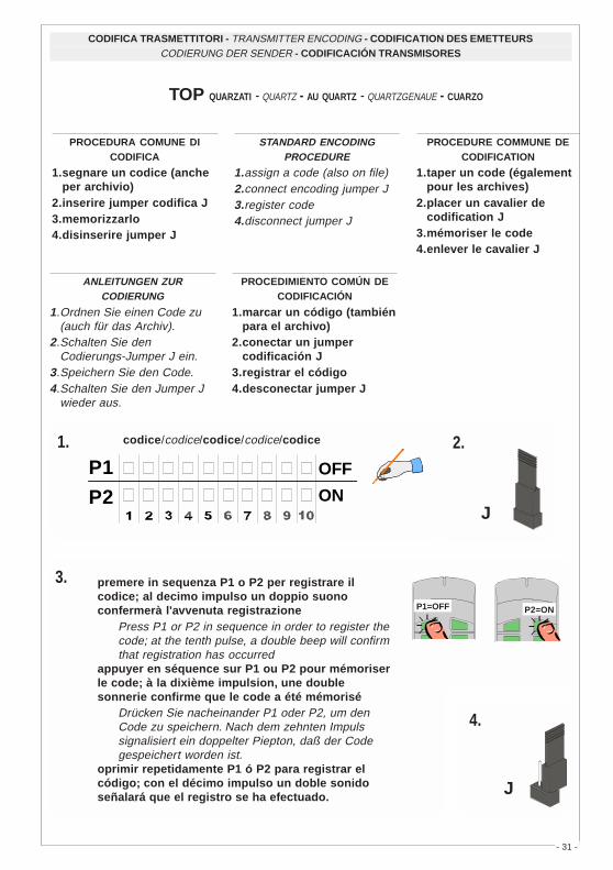
PROCEDURA COMUNE DICODIFICA
1.segnare un codice (ancheper archivio)
2.inserire jumper codifica J3.memorizzarlo4.disinserire jumper J
STANDARD ENCODINGPROCEDURE
1.assign a code (also on file)2.connect encoding jumper J3.register code4.disconnect jumper J
PROCEDURE COMMUNE DECODIFICATION
1.taper un code (égalementpour les archives)
2.placer un cavalier decodification J
3.mémoriser le code4.enlever le cavalier J
ANLEITUNGEN ZURCODIERUNG
1.Ordnen Sie einen Code zu(auch für das Archiv).
2.Schalten Sie denCodierungs-Jumper J ein.
3.Speichern Sie den Code.4.Schalten Sie den Jumper J
wieder aus.
PROCEDIMIENTO COMÚN DECODIFICACIÓN
1.marcar un código (tambiénpara el archivo)
2.conectar un jumpercodificación J
3.registrar el código4.desconectar jumper J
premere in sequenza P1 o P2 per registrare ilcodice; al decimo impulso un doppio suonoconfermerà l'avvenuta registrazione
Press P1 or P2 in sequence in order to register thecode; at the tenth pulse, a double beep will confirmthat registration has occurred
appuyer en séquence sur P1 ou P2 pour mémoriserle code; à la dixième impulsion, une doublesonnerie confirme que le code a été mémorisé
Drücken Sie nacheinander P1 oder P2, um denCode zu speichern. Nach dem zehnten Impulssignalisiert ein doppelter Piepton, daß der Codegespeichert worden ist.
oprimir repetidamente P1 ó P2 para registrar elcódigo; con el décimo impulso un doble sonidoseñalará que el registro se ha efectuado.
2.
J
3.
ON
OFFP1
P2
codice/codice/codice/codice/codice1.
4.
J
P1=OFF P2=ON
TOP QUARZATI - QUARTZ - AU QUARTZ - QUARTZGENAUE - CUARZO

- 32 -
La prima codifica deve essere effettuata mantenendo i jumperposizionati per i canali 1 e 2 come da fig. A; per eventuali e succes-sive impostazioni su canali diversi vedi fig. B
The first encoding operation must be carried out whilst keeping thejumpers positioned for channels 1 and 2 as per fig. A; see fig. B forany subsequent settings on different channels.
La première codification doit être effectuée en maintenant lescavaliers en position pour les canaux 1 et 2, comme d'après la fig.A; pour des saisies successives éventuelles sur des canauxdifférents, voir fig. B
Für die erste Codierung muß der Jumper auf den Kanälen 1 und 2positioniert bleiben (siehe Abb. A). Für eventuelle weitere oderspätere Einstellungen auf anderen Kanälen halten Sie sich bitte anAbb. B.
La primera codificación tiene que efectuarse manteniendo losjumper conectados para los canales 1 y 2 como se ilustra en la fig.A; para planteamientos posteriores en canales distintos ver la fig. B
T262M - T302M
P1 P2
J
T2622M - T3022M
P1 P2
P3 P4
P1=CH1 - P2=CH2P3=CH3 - P4=CH4
J
T264M - T304M
P1=CH1P2=CH2
fig. A
2° codice/codice/codice/codice/codice
ON
OFFP1P2
P3=CH1P4=CH2
J
1° codice/codicecodice/codice/codice
P1 P2
P3 P4
P1=CH1P2=CH2
J
fig. B
P1=CH1 - P2=CH4
P1=CH1 - P2=CH3 P1=CH3 - P2=CH2
P1=CH3 - P2=CH4
CODIFICA TRASMETTITORI - TRANSMITTER ENCODING - CODIFICATION DES EMETTEURSCODIERUNG DER SENDER - CODIFICACIÓN TRANSMISORES
TOP QUARZATI - QUARTZ - AU QUARTZ - QUARTZGENAUE - CUARZO

- 33 -
ITALIANO
-Tenere premutoil tasto "CH1"sulla schedabase e dopol'accensione delled di segnala-zione, inviare uncomando con untasto deltrasmettitore, unbreve lampeggiodel led segnale-rà l'avvenutamemorizzazione(vedi fig.1).-Eseguire lastessa procedu-ra con il tasto"CH2" associan-dolo con un'altrotasto deltrasmettitore(fig.2).CH1 = Canaleper comandidiretti ad unafunzione dellacentralina delmotoriduttore(comando "soloapre" / "apre-chiude-inversio-ne" oppure"apre-stop-chiude-stop", aseconda dellaselezioneeffetuata sui dip-switch 2 e 3).CH2 = Canaleper comandidiretti ad undispositivoaccessoriocollegato su B1-B2.
ENGLISH-While holdingdown key "CH1",press the controlkey on thetransmitter afterthe signal LEDlights up. Whenthe key ispressed, theLED will flashbriefly to signalthat thecommand hasbeen stored(figure 1).-Perform thesame procedurewith the CH2key, associatingit with anothertransmitter key(figure 2).CH1 = Channelfor direct controlof one functionperformed bythe control uniton the gearmotor ("openonly" / "open-close-reverse"or "open-stop-close-stop",depending onthe position ofdip switches 2and 3).CH2 = Channelfor direct controlof an accessoryconnectedacross B1-B2.
FRANÇAIS-En maintenantappuyée latouche "CH1" etaprés que le ledde signalisations'est allumé,envoyer unecommande avecla touche del'émetteur: unbrefclignotement duled signaleraque lamémorisation aété exécutée.(fig.1).-Suivre la mêmeprocédure avecla touche "CH2"en l'associantavec une autretouche duemetteur (fig.2).CH1 = Canalpour obtenir lacommandedirecte d'unefonction duboîtier dumotoréducteur (commande"uniquementouverture" /"ouverture-fermeture-inversion" ou"ouverte-stop-ferme-stop" enfonction de lasélectioneffectuée sur lesdip-switchs 2 et3).CH2 = Canalpour obtenir lacommandedirecte d'undispositifaccessoirebranché sur B1-B2.
DEUTSCH
-Die Taste"CH1" gedrückthalten und nachAufleuchten derAnzeige-Leuchtdiodeüber denSender-TastereinenSteuerimpulsausführen: einkurzes Blinkender Led zeigt dieerfolgteSpeicherung an(Abb.1).-Gehen Sieebenso mitTaste CH2 vorund ordnen sieihr eine andereTaste desSenders zu(Abb.2).CH1 = Kanal fürdieDirektsteuerungeiner FunktiondesGetriebemotor-Schaltkastens(Steuerung "nurÖffnen" /"Öffnen-Schließen-Sicherheitsrücklauf"bzw. "Öffnen-Stp-Schließen-Stop", je nachüber Dip-Switch2 und 3ausgeführterWahl).CH2 = Kanal fürDirektsteuerungeines über B1-B2angeschlossenenZubehörs.
ESPANOL-Manteniendopulsada latecla "CH1" ydespués delencendido delLED de señalcon la tecla deltransmisor: unabreve luzparpadeantedel LEDseñalará que lamemorizaciónha sidoefectuada(fig.1).-Efectuar elmismoprocedimientocon la tecla"CH2"asociándola aotra tecla deltransmisor(fig.2).CH1 = Canalpara mandodirecto a unafunción de lacentral delmotorreductor(mando "soloabre" / "abre-cierra-inversión" o"abre-stop-cierra-stop",según laselecciónefectuada enlos dip-switch 2y 3).CH2 = Canalpara un mandodirecto a undispositivoaccesorioconectado enB1-B2.
MEMORIZZAZIONE CODICE - CODE STORAGE - MEMORISATION DU CODESPEICHERN VOM CODE - MEMORIZACIÓN CÓDIGOC

- 34 -
CH2CH1
21 3 4 5 6 7 8 9 10
ON
1211 13 14 15 16 17 18 19 20
ON
CH2CH1
21 3 4 5 6 7 8 9 1 0
O N
1 21 1 1 3 1 4 1 5 1 6 1 7 1 8 1 9 2 0
O N
Scheda radiofrequenza AF
AF radiofrequency board
Carte radiofrèquence AF
Funkfrequenz-Platine AF
Tarjeta radiofrecuencia AF
�!�
�!�
LED di segnalazione codice radio
Radio code signal LED
LED de signalisation code radio
Funkcode-Anzeigeleuchtdiode
LED de señal código radio
��)�����)��
��)�����)��
N.B.: se in seguito si vuol cambiare codice, basta ripetere la sequenza descritta.
N.B. If you wish to change the code on your transmitters in the future, simply repeat theprocedure described above.
Remarque: si, successivement, on veut changer le code des émetteur, il suffit de répéterla séquence décrite ci-dessus.
Hinweis: bei eventuell erwünschter Sender codeänderung ist der beschriebene Vorgangzu wiederholen.
Nota: si posteriormente se quisiera cambiar el código de los propios transmisores, sólohay que repetir la secuencia descrita.

- 35 -
Assemblare le cerniere a pressioneAssemble the hinges by pressureAssembler les charnières à pressionSetzen Sie die Druckscharnierezusammen.Ensamblar las bisagras a presión
Inserire le cerniere nella scatola (sullato destro o sinistro a scelta) efermarle con le viti e le rondelle indotazioneInsert the hinges (on the right or left side,according to choice) and secure using thescrews and washers suppliedPlacer les charnières (du côté droit ougauche au choix) et les fixer avec lesvis et les rondelles fournies de sérieSetzen Sie die Scharniere ein (je nachWunsch auf der rechten oder linken Seite)und befestigen Sie sie mit denmitgelieferten Schrauben undUnterlegscheibenIntroducir las bisagras (en el ladoizquierdo o derecho, a placer) y fijarlascon los tornillos y las arandelassuministradas a tal efecto
2
scorrono per ruotarethey must slide inorder to turnelles glissent pourtournerlaufen zum Drehendeslizan para girar
15 mm~
1
!!
Posizionare e fissare la scatola delquadroPosition and secure the control panelhousingPlacer et fixer la boîte de l'armoirePlazieren Sie das Gehäuse der Schalttafelund befestigen Sie es.Colocar y sujetar la caja del cuadro
3Inserire a scatto il coperchio sulle cernie-re, chiuderlo e fissarlo con le viti indotazioneSnap the cover onto the hinges and secureusing the screws supplied.Assembler par encliquetage le couverclesur les charnières et fixer le couvercleavec les vis fournies de sérieLassen Sie den Deckel in den Scharniereneinrasten und befestigen Sie ihn mit denmitgelieferten Schrauben.Introducir la tapa en las bisagras hastaoír un chasquido y fijar la tapa con lostornillos suministrados a tal efecto.
215 mm
295
mm
4
ISTRUZIONI MONTAGGIO CERNIERE - ASSEMBLY INSTRUCTIONS S4340 HINGESINSTRUCTIONS MONTAGE CHARNIÈRES S4340
MONTAGEANWEISUNGEN SCHARNIERE S4340 - INSTRUCCIONES MONTAJE BISAGRAS S4340

CAME LOMBARDIA S.R.L.___COLOGNO M. (MI)(+39) 02 26708293 (+39) 02 25490288
CAME SUD S.R.L. _________________NAPOLI(+39) 081 7524455 (+39) 081 7529109
CAME (AMERICA) L.L.C._________MIAMI (FL)(+1) 305 5930227 (+1) 305 5939823
CAME AUTOMATISMOS S.A_________MADRID(+34) 091 5285009 (+34) 091 4685442
CAME BELGIUM____________LESSINES(+32) 068 333014 (+32) 068 338019
CAME CANCELLI AUTOMATICI S.P.A.DOSSON DI CASIER (TREVISO)
(+39) 0422 4940 (+39) 0422 4941
CAME FRANCE S.A.___NANTERRE CEDEX (PARIS)(+33) 01 46130505 (+33) 01 46130500
CAME GMBH____KORNTAL BEI (STUTTGART)(+49) 07 11839590 (+49) 07 118395925
CAME GMBH________SEEFELD BEI (BERLIN)(+49) 03 33988390 (+49) 03 339885508
CAME PL SP.ZO.O_________WARSZAWA(+48) 022 8365076 (+48) 022 8369920
CAME UNITED KINGDOM LTD___NOTTINGHAM(+44) 01159 387200 (+44) 01159 382694
ASSISTENZA TECNICA
NUMERO VERDE
800 295830
WEBwww.came.it
SISTEMA QUALITÀCERTIFICATO
CANCELLI AUTOMATICI
Tutti i dati sono stati controllati con la mas-sima cura. Non ci assumiamo comunquealcuna responsabilità per eventuali erroriod omissioni.
All data checked with the maximum care.However, no liability is accepted for anyerror or omission.
Toutes les données ont été contrôléestrès soigneusement. Nous n’assumons detoute façon aucune responsabilité pourles erreurs ou omissions éventuelles.
Die Daten wurden mit höchster Sorgfaltgeprüft. Für eventuelle Fehler oderAuslassungen übernehmen wir keineHaftung.
Todos los datos se han controlado conla máxima atención. No obstante no nosresponsabilizamos de los posibleserrores u omisiones.