Frame Assembly and Installation Guide for Andersen 400 ...
16
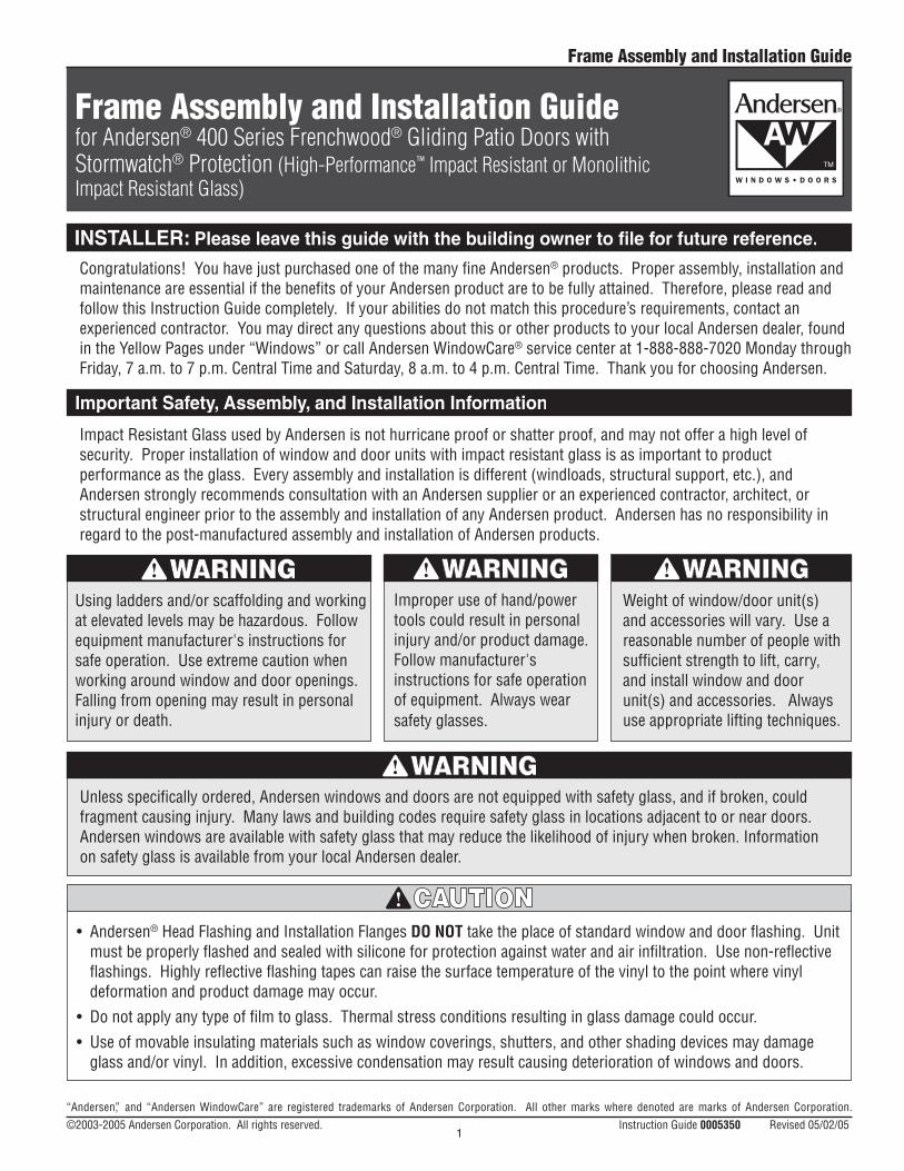
“Andersen” , and “Andersen WindowCare” are registered trademarks of Andersen Corporation. All other marks where denoted are marks of Andersen Corporation. ©2003-2005 Andersen Corporation. All rights reserved. Instruction Guide 0005350 Revised 05/02/05 Weight of window/door unit(s) and accessories will vary. Use a reasonable number of people with sufficient strength to lift, carry, and install window and door unit(s) and accessories. Always use appropriate lifting techniques. Using ladders and/or scaffolding and working at elevated levels may be hazardous. Follow equipment manufacturer's instructions for safe operation. Use extreme caution when working around window and door openings. Falling from opening may result in personal injury or death. Improper use of hand/power tools could result in personal injury and/or product damage. Follow manufacturer's instructions for safe operation of equipment. Always wear safety glasses. Impact Resistant Glass used by Andersen is not hurricane proof or shatter proof, and may not offer a high level of security. Proper installation of window and door units with impact resistant glass is as important to product performance as the glass. Every assembly and installation is different (windloads, structural support, etc.), and Andersen strongly recommends consultation with an Andersen supplier or an experienced contractor, architect, or structural engineer prior to the assembly and installation of any Andersen product. Andersen has no responsibility in regard to the post-manufactured assembly and installation of Andersen products. Congratulations! You have just purchased one of the many fine Andersen ® products. Proper assembly, installation and maintenance are essential if the benefits of your Andersen product are to be fully attained. Therefore, please read and follow this Instruction Guide completely. If your abilities do not match this procedure’s requirements, contact an experienced contractor. You may direct any questions about this or other products to your local Andersen dealer, found in the Yellow Pages under “Windows” or call Andersen WindowCare ® service center at 1-888-888-7020 Monday through Friday, 7 a.m. to 7 p.m. Central Time and Saturday, 8 a.m. to 4 p.m. Central Time. Thank you for choosing Andersen. • Andersen ® Head Flashing and Installation Flanges DO NOT take the place of standard window and door flashing. Unit must be properly flashed and sealed with silicone for protection against water and air infiltration. Use non-reflective flashings. Highly reflective flashing tapes can raise the surface temperature of the vinyl to the point where vinyl deformation and product damage may occur. • Do not apply any type of film to glass. Thermal stress conditions resulting in glass damage could occur. • Use of movable insulating materials such as window coverings, shutters, and other shading devices may damage glass and/or vinyl. In addition, excessive condensation may result causing deterioration of windows and doors. Unless specifically ordered, Andersen windows and doors are not equipped with safety glass, and if broken, could fragment causing injury. Many laws and building codes require safety glass in locations adjacent to or near doors. Andersen windows are available with safety glass that may reduce the likelihood of injury when broken. Information on safety glass is available from your local Andersen dealer. Frame Assembly and Installation Guide for Andersen ® 400 Series Frenchwood ® Gliding Patio Doors with Stormwatch ® Protection (High-Performance ™ Impact Resistant or Monolithic Impact Resistant Glass) 1 Frame Assembly and Installation Guide
-
Upload
khangminh22 -
Category
Documents
-
view
1 -
download
0
Transcript of Frame Assembly and Installation Guide for Andersen 400 ...
“Andersen”, and “Andersen WindowCare” are registered trademarks of Andersen Corporation. All other marks where denoted are marks of Andersen Corporation. ©2003-2005 Andersen Corporation. All rights reserved. Instruction Guide 0005350 Revised 05/02/05
Weight of window/door unit(s) and accessories will vary. Use a reasonable number of people with sufficient strength to lift, carry, and install window and door unit(s) and accessories. Always use appropriate lifting techniques.
Using ladders and/or scaffolding and working at elevated levels may be hazardous. Follow equipment manufacturer's instructions for safe operation. Use extreme caution when working around window and door openings. Falling from opening may result in personal injury or death.
Improper use of hand/power tools could result in personal injury and/or product damage. Follow manufacturer's instructions for safe operation of equipment. Always wear safety glasses.
Impact Resistant Glass used by Andersen is not hurricane proof or shatter proof, and may not offer a high level of security. Proper installation of window and door units with impact resistant glass is as important to product performance as the glass. Every assembly and installation is different (windloads, structural support, etc.), and Andersen strongly recommends consultation with an Andersen supplier or an experienced contractor, architect, or structural engineer prior to the assembly and installation of any Andersen product. Andersen has no responsibility in regard to the post-manufactured assembly and installation of Andersen products.
Congratulations! You have just purchased one of the many fine Andersen® products. Proper assembly, installation and maintenance are essential if the benefits of your Andersen product are to be fully attained. Therefore, please read and follow this Instruction Guide completely. If your abilities do not match this procedure’s requirements, contact an experienced contractor. You may direct any questions about this or other products to your local Andersen dealer, found in the Yellow Pages under “Windows” or call Andersen WindowCare® service center at 1-888-888-7020 Monday through Friday, 7 a.m. to 7 p.m. Central Time and Saturday, 8 a.m. to 4 p.m. Central Time. Thank you for choosing Andersen.
• Andersen® Head Flashing and Installation Flanges DO NOT take the place of standard window and door flashing. Unit must be properly flashed and sealed with silicone for protection against water and air infiltration. Use non-reflective flashings. Highly reflective flashing tapes can raise the surface temperature of the vinyl to the point where vinyl deformation and product damage may occur.
• Do not apply any type of film to glass. Thermal stress conditions resulting in glass damage could occur.
• Use of movable insulating materials such as window coverings, shutters, and other shading devices may damage glass and/or vinyl. In addition, excessive condensation may result causing deterioration of windows and doors.
Unless specifically ordered, Andersen windows and doors are not equipped with safety glass, and if broken, could fragment causing injury. Many laws and building codes require safety glass in locations adjacent to or near doors. Andersen windows are available with safety glass that may reduce the likelihood of injury when broken. Information on safety glass is available from your local Andersen dealer.
Frame Assembly and Installation Guidefor Andersen® 400 Series Frenchwood® Gliding Patio Doors with Stormwatch® Protection (High-Performance™ Impact Resistant or Monolithic Impact Resistant Glass)
1
Frame Assembly and Installation Guide
PLU
M -
LEVE
L - S
HIM
PLU
M -
LEVE
L - S
HIM
PLU
M -
LEVE
L - S
HI M
PLUM
- LEVEL - SHIM
PLUM
- LEVEL - SHIM
PLUM
- L E
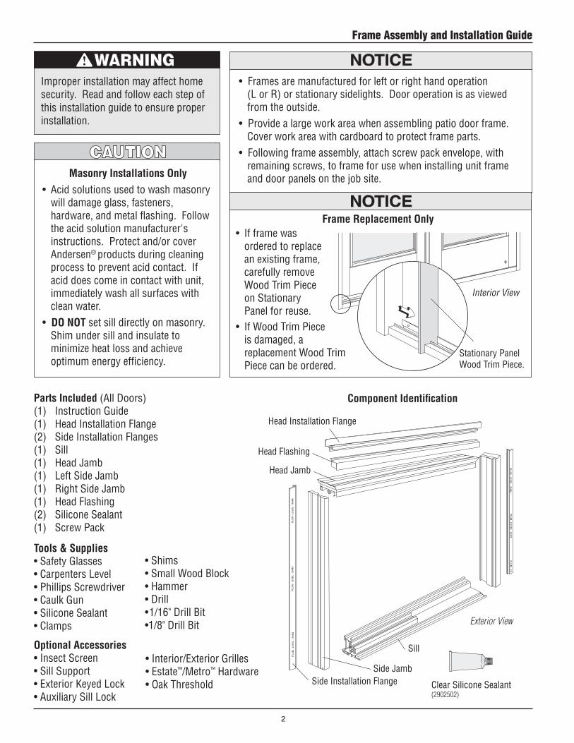
Optional Accessories• Insect Screen• Sill Support• Exterior Keyed Lock• Auxiliary Sill Lock
Tools & Supplies• Safety Glasses • Carpenters Level• Phillips Screwdriver• Caulk Gun• Silicone Sealant• Clamps
Parts Included (All Doors)(1) Instruction Guide(1) Head Installation Flange(2) Side Installation Flanges(1) Sill (1) Head Jamb(1) Left Side Jamb(1) Right Side Jamb(1) Head Flashing(2) Silicone Sealant(1) Screw Pack
• Frames are manufactured for left or right hand operation (L or R) or stationary sidelights. Door operation is as viewed from the outside.
• Provide a large work area when assembling patio door frame. Cover work area with cardboard to protect frame parts.
• Following frame assembly, attach screw pack envelope, with remaining screws, to frame for use when installing unit frame and door panels on the job site.
Improper installation may affect home security. Read and follow each step of this installation guide to ensure proper installation.
Head Installation Flange
Head Flashing
Head Jamb
Side Installation FlangeSide Jamb
Clear Silicone Sealant (2902502)
Exterior View
Sill
Component Identification
• Shims• Small Wood Block• Hammer• Drill• 1/16" Drill Bit•1/8" Drill Bit
• Interior/Exterior Grilles• Estate™/Metro™ Hardware• Oak Threshold
Masonry Installations Only• Acid solutions used to wash masonry
will damage glass, fasteners, hardware, and metal flashing. Follow the acid solution manufacturer's instructions. Protect and/or cover Andersen® products during cleaning process to prevent acid contact. If acid does come in contact with unit, immediately wash all surfaces with clean water.
• DO NOT set sill directly on masonry. Shim under sill and insulate to minimize heat loss and achieve optimum energy efficiency.
Stationary Panel Wood Trim Piece.
Interior View
• If frame was ordered to replace an existing frame, carefully remove Wood Trim Piece on Stationary Panel for reuse.
Frame Replacement Only
• If Wood Trim Piece is damaged, a replacement Wood Trim Piece can be ordered.
Frame Assembly and Installation Guide
2

*Side Stop
* Identifies parts/screws for panel installation. Frame and panels are packaged separately. Please keep remaining parts/screws for panel installation.
(1) Side Stop*(1) Stationary Panel Interlock Weatherstrip* (1) Operating Panel Interlock Weatherstrip*(2) Universal Stiffener Bracket*(1) Operating Panel Stiffener*(1) Stationary Panel Stiffener*(2) Panel Hole Plug*(1) Insect Screen Latch(1) Parting Stop Bracket*(22) #7 x 5/8" Colored Pan Head Screws*(11) #8 x 1" Colored Flat Head Screws*(6) #8 x 1” Gray Flat Head Screws*(1) #8 x 1” Stainless Round Head Screw (10) #8 x 1-1/2” Colored Flat Head Screws*(5) #10 x 1” Stainless Pan Head Screws(45) #10 x 2-1/2” Flat Head Screws (color matching)(3) #10 x 2-1/2” Gray Pan Head Screws(6) #10 x 2” Oval Head Screws (color matching)(6) #10 x 2” Beige Oval Head Screws
(2) Side Stops*(12) #8 x 1" Screws (color matching)*(4) #8 x 1” Gray Screws*(37) #10 x 2-1/2” Screws (color matching) *Stationary Panel
Interlock Weatherstrip*Operating Panel Inter-lock Weatherstrip
Additional Parts (Stationary Sidelight)
Additional Parts (2-Panel Door)
*Universal Stiffener Bracket (2579406) Stainless
*Operating Panel Stiffener *Stationary Panel Stiffener
*Panel Hole Plug (2653804) Gray
Insect Screen Latch(2579551) White(0924602) Sandtone(1267822) Forest Green
*Parting Stop Bracket (0912717) White (2573692) Gray
*#7
x 5/
8" C
olor
ed P
an H
ead
Scre
ws
(
1973
109)
Whi
te, (2
6412
10) G
ray
*#8
x 1”
Col
ored
Fla
t Hea
d Sc
rew
s
(250
0702
) Whi
te, (2
6538
62) T
erra
tone
®,
(250
0704
) San
dton
e, (2
5007
04) G
ray
#8 x
1”
Roun
d He
ad S
crew
(197
3110
) Stai
nles
s
*#8
x 1-
1/2”
Col
ored
Fla
t Hea
d Sc
rew
s
(197
3111
) Whi
te, (2
6538
61) T
erra
tone
® , (
3629
039)
San
dton
e,
(2
5007
01) G
old
#10
x 2-
1/2”
Col
ored
Fla
t Hea
d Sc
rew
s
(197
3114
) Whi
te, (2
6412
11) T
erra
tone
® (0
9410
9) S
andt
one
#10
x 2-
1/2”
Pan
Hea
d Sc
rew
s
(091
2718
) Gra
y
#10
x 2”
Col
ored
Ova
l Hea
d Sc
rew
s
(257
9403
) Whi
te, (2
6538
69) T
erra
tone
® (0
9127
19) S
andt
one,
(257
9404
) Beig
e
#10
x 1”
Pan
Hea
d Sc
rew
s
(257
9405
) Stai
nles
s
• Steel fasteners will corrode when used with ACQ Pressure Treated Lumber.• Obtain and use the appropriate size stainless steel screws, as called out in this installation guide, to fasten unit to
any rough opening made from ACQ Pressure Treated Lumber.• Failure to use stainless steel fasteners may result in fastener corrosion causing product damage.
3
Frame Assembly and Installation Guide
THIS SCREW FIRST
READ INSTRUCTIONS
THIS SCREW FIRST
READ INSTRUCTIONS
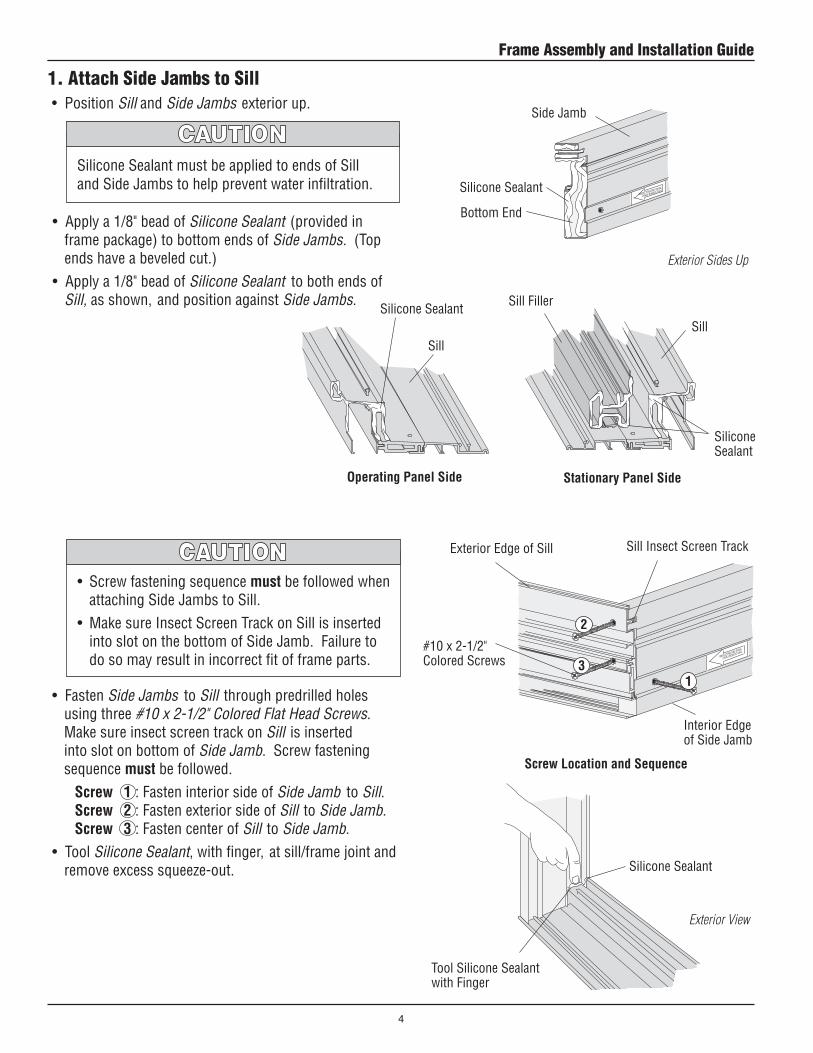
1. Attach Side Jambs to Sill
• Apply a 1/8" bead of Silicone Sealant (provided in frame package) to bottom ends of Side Jambs. (Top ends have a beveled cut.)
• Apply a 1/8" bead of Silicone Sealant to both ends of Sill, as shown, and position against Side Jambs.
• Fasten Side Jambs to Sill through predrilled holes using three #10 x 2-1/2" Colored Flat Head Screws. Make sure insect screen track on Sill is inserted into slot on bottom of Side Jamb. Screw fastening sequence must be followed.
Screw 1 : Fasten interior side of Side Jamb to Sill. Screw 2 : Fasten exterior side of Sill to Side Jamb. Screw 3 : Fasten center of Sill to Side Jamb.
• Tool Silicone Sealant, with finger, at sill/frame joint and remove excess squeeze-out.
Silicone Sealant must be applied to ends of Sill and Side Jambs to help prevent water infiltration.
• Screw fastening sequence must be followed when attaching Side Jambs to Sill.
• Make sure Insect Screen Track on Sill is inserted into slot on the bottom of Side Jamb. Failure to do so may result in incorrect fit of frame parts.
Side Jamb
Silicone Sealant
Screw Location and Sequence
Interior Edge of Side Jamb
Exterior Edge of Sill
13
2
• Position Sill and Side Jambs exterior up.
Sill Insect Screen Track
Silicone Sealant
Bottom End
#10 x 2-1/2" Colored Screws
Tool Silicone Sealant with Finger
Exterior View
Exterior Sides Up
Operating Panel Side
Sill
Silicone Sealant
Stationary Panel Side
Sill
Silicone Sealant
Sill Filler
Frame Assembly and Installation Guide
4
PLUMB - LEVEL - SHIMPLU
PLUMB - LE
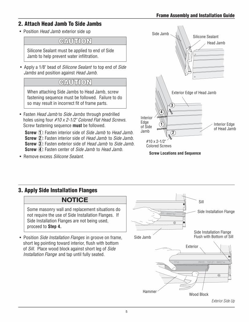
2. Attach Head Jamb To Side Jambs
• Apply a 1/8" bead of Silicone Sealant to top end of Side Jambs and position against Head Jamb.
Silicone Sealant must be applied to end of Side Jamb to help prevent water infiltration.
Interior Edge of Head Jamb
Side Jamb
Head Jamb
Interior Edge of Side Jamb
Screw Locations and Sequence
When attaching Side Jambs to Head Jamb, screw fastening sequence must be followed. Failure to do so may result in incorrect fit of frame parts.
• Fasten Head Jamb to Side Jambs through predrilled holes using four #10 x 2-1/2" Colored Flat Head Screws. Screw fastening sequence must be followed.
Screw 1 : Fasten interior side of Side Jamb to Head Jamb. Screw 2 : Fasten interior side of Head Jamb to Side Jamb. Screw 3 : Fasten exterior side of Head Jamb to Side Jamb. Screw 4 : Fasten center of Side Jamb to Head Jamb.
• Remove excess Silicone Sealant.
Silicone Sealant
Exterior Edge of Head Jamb
1
2
3
4
3. Apply Side Installation Flanges
• Position Side Installation Flanges in groove on frame, short leg pointing toward interior, flush with bottom of Sill. Place wood block against short leg of Side Installation Flange and tap until fully seated.
Some masonry wall and replacement situations do not require the use of Side Installation Flanges. If Side Installation Flanges are not being used, proceed to Step 4.
Sill
Side Installation Flange
Side JambSide Installation FlangeFlush with Bottom of Sill
Wood Block
• Position Head Jamb exterior side up
Exterior
#10 x 2-1/2" Colored Screws
Exterior Side Up
Hammer
5
Frame Assembly and Installation Guide
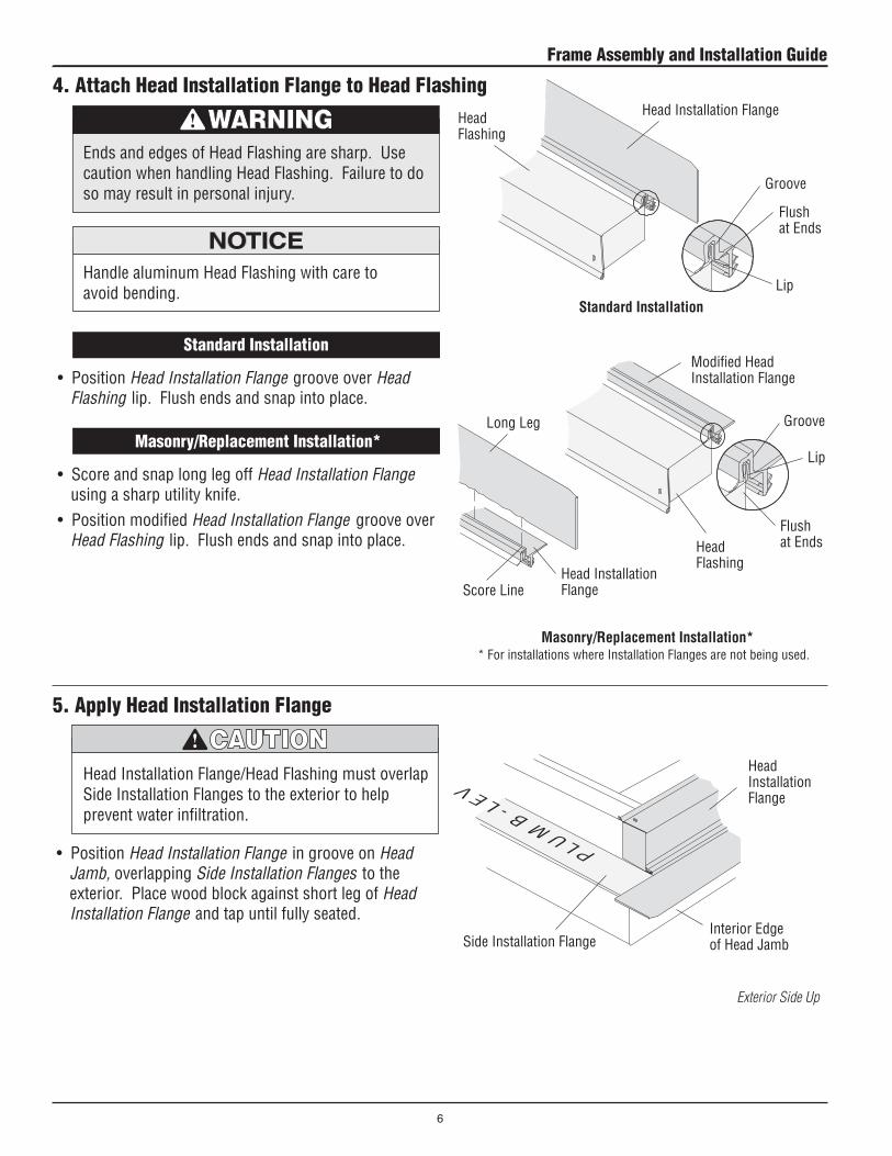
5. Apply Head Installation Flange
• Position Head Installation Flange in groove on Head Jamb, overlapping Side Installation Flanges to the exterior. Place wood block against short leg of Head Installation Flange and tap until fully seated.
Head Installation Flange
Side Installation Flange
Head Installation Flange/Head Flashing must overlap Side Installation Flanges to the exterior to help prevent water infiltration.
Interior Edge of Head Jamb
4. Attach Head Installation Flange to Head Flashing
Standard Installation
Masonry/Replacement Installation*
• Position Head Installation Flange groove over Head Flashing lip. Flush ends and snap into place.
• Score and snap long leg off Head Installation Flange using a sharp utility knife.
• Position modified Head Installation Flange groove over Head Flashing lip. Flush ends and snap into place.
Head Installation FlangeHead Flashing
Flush at Ends
* For installations where Installation Flanges are not being used.
Handle aluminum Head Flashing with care to avoid bending.
Head Flashing
Modified Head Installation Flange
Head Installation Flange
Long Leg
Score Line
Standard Installation
Masonry/Replacement Installation*
Groove
Lip
Flush at Ends
Groove
Lip
Ends and edges of Head Flashing are sharp. Use caution when handling Head Flashing. Failure to do so may result in personal injury.
Exterior Side Up
Frame Assembly and Installation Guide
6

Rough Opening
Height
Rough Opening
Width
7. Check Rough Opening• Check dimension of rough opening for correct size.• Check sill plate for level. Sill must be level, shim sill
plate if necessary. • Check rough opening for plumb and level. If rough
opening is not plumb or level, correct as necessary. • Check rough opening for square by measuring
diagonally, upper left to lower right and upper right to lower left corner. If measurements are the same, opening is square. If rough opening is not square, correct as necessary.
• Slide aluminum Sill Support onto the aluminum Sill from one end. DO NOT secure with screws until siding or exterior finish is applied over sheathing.
6. Apply Optional Aluminum Sill Support if Required
Sill support must be used whenever support is needed under projecting outer edge of Sill. Support entire length of Sill to prevent product damage.
Optional Aluminum Sill Support
Optional aluminum Exterior Sill Extension and Sill Support must be applied before frame is installed.
Masonry Construction
Standard Construction
Exterior Interior
Sill
(Shown installed)
Optional Aluminum Sill Support
Exterior View
Level Exterior Views
Cross Section Detail
7
Frame Assembly and Installation Guide
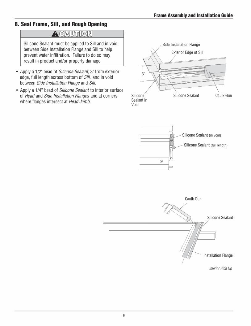
Silicone SealantSilicone Sealant in Void
• Apply a 1/2" bead of Silicone Sealant, 3" from exterior edge, full length across bottom of Sill, and in void between Side Installation Flange and Sill.
• Apply a 1/4” bead of Silicone Sealant to interior surface of Head and Side Installation Flanges and at corners where flanges intersect at Head Jamb.
Silicone Sealant must be applied to Sill and in void between Side Installation Flange and Sill to help prevent water infiltration. Failure to do so may result in product and/or property damage.
Exterior Edge of Sill
3"
Side Installation Flange
8. Seal Frame, Sill, and Rough Opening
Interior Side Up
Silicone Sealant
Caulk Gun
Silicone Sealant (in void)
Silicone Sealant (full length)
Installation Flange
Caulk Gun
Frame Assembly and Installation Guide
8

PLU
M -
LEV
EL -
SH
IMPL
UM
- L
EVEL
- S
H
Shim
• Insert shims between Side Jambs and framing at each fastener location. Shims will be held in place by fastener screws.
• Insert shims between Head Jamb and framing. DO NOT place shims on top of predrilled holes. Shims at Head Jamb are temporary.
• Check Head and Side Jambs for level. Make adjustments using shims if necessary. Jambs must be plumb, level, and square.
Allow 1/4" space around perimeter of unit between exterior finish and door frame for Silicone Sealant.
Clamp
Side Jamb
Level
Head Jamb
10. Shim and Plumb Jambs
Interior View
Exterior View
Side Jamb
SHIM
PLU
M -
LEV
EL -
SH
Temporary Blocking Material
Sill
Cross Section Detail
• Center frame horizontally in rough opening from the exterior. Apply downward pressure on Sill to spread Silicone Sealant.
• Clamp door frame to rough opening using clamps and surface protectors.
9. Position in Rough Opening and Clamp
Exterior Interior
ClampSurface Protector
Exterior View
Flange
Clamp
Interior View
Frame
Framing
Blocking material must be used whenever support is needed under the projecting outer edge of Sill. Support entire length of Sill to prevent product damage.
• Fasten blocking material under projecting, exterior edge of Sill to provide support. Remove temporary blocking prior to installation of permanent blocking or decking.
Surface Protector
Silicone Sealant (in void)
9
Frame Assembly and Installation Guide
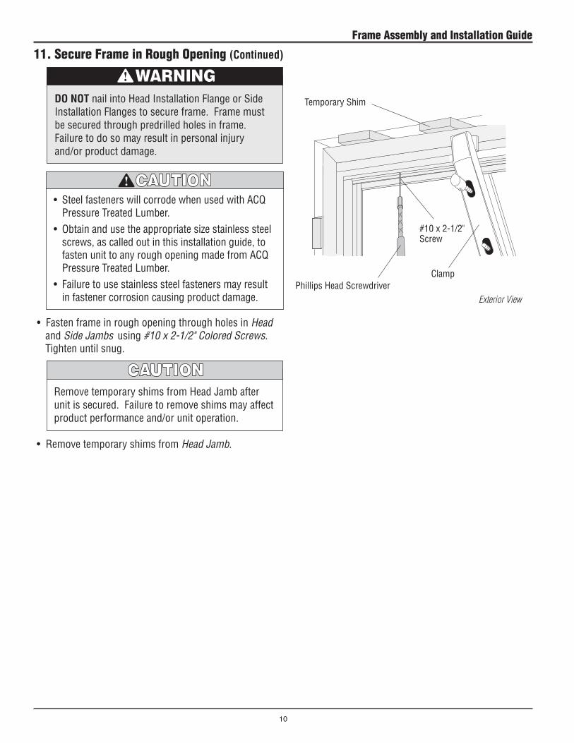
• Fasten frame in rough opening through holes in Head and Side Jambs using #10 x 2-1/2" Colored Screws. Tighten until snug.
Temporary Shim
#10 x 2-1/2" Screw
Remove temporary shims from Head Jamb after unit is secured. Failure to remove shims may affect product performance and/or unit operation.
Exterior View
• Remove temporary shims from Head Jamb.
Phillips Head ScrewdriverClamp
11. Secure Frame in Rough Opening (Continued)
DO NOT nail into Head Installation Flange or Side Installation Flanges to secure frame. Frame must be secured through predrilled holes in frame. Failure to do so may result in personal injury and/or product damage.
• Steel fasteners will corrode when used with ACQ Pressure Treated Lumber.
• Obtain and use the appropriate size stainless steel screws, as called out in this installation guide, to fasten unit to any rough opening made from ACQ Pressure Treated Lumber.
• Failure to use stainless steel fasteners may result in fastener corrosion causing product damage.
Frame Assembly and Installation Guide
10
Aluminum Sill Support
Exterior View
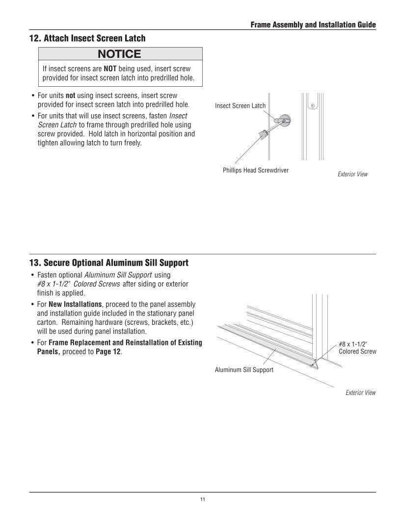
• Fasten optional Aluminum Sill Support using #8 x 1-1/2" Colored Screws after siding or exterior finish is applied.
• For New Installations, proceed to the panel assembly and installation guide included in the stationary panel carton. Remaining hardware (screws, brackets, etc.) will be used during panel installation.
• For Frame Replacement and Reinstallation of Existing Panels, proceed to Page 12.
13. Secure Optional Aluminum Sill Support
#8 x 1-1/2" Colored Screw
12. Attach Insect Screen Latch
Insect Screen Latch• For units not using insect screens, insert screw
provided for insect screen latch into predrilled hole.
• For units that will use insect screens, fasten Insect Screen Latch to frame through predrilled hole using screw provided. Hold latch in horizontal position and tighten allowing latch to turn freely.
If insect screens are NOT being used, insert screw provided for insect screen latch into predrilled hole.
Exterior View Phillips Head Screwdriver
11
Frame Assembly and Installation Guide
Reinstallation of Existing Panels
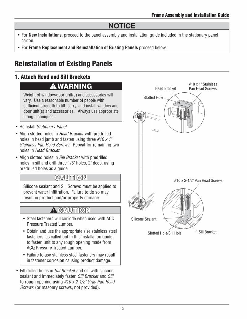
#10 x 2-1/2" Pan Head Screws
Sill BracketSlotted Hole/Sill Hole
• Fill drilled holes in Sill Bracket and sill with silicone sealant and immediately fasten Sill Bracket and Sill to rough opening using #10 x 2-1/2" Gray Pan Head Screws (or masonry screws, not provided).
1. Attach Head and Sill Brackets
• Reinstall Stationary Panel.• Align slotted holes in Head Bracket with predrilled
holes in head jamb and fasten using three #10 x 1" Stainless Pan Head Screws. Repeat for remaining two holes in Head Bracket.
• Align slotted holes in Sill Bracket with predrilled holes in sill and drill three 1/8" holes, 2" deep, using predrilled holes as a guide.
• Steel fasteners will corrode when used with ACQ Pressure Treated Lumber.
• Obtain and use the appropriate size stainless steel fasteners, as called out in this installation guide, to fasten unit to any rough opening made from ACQ Pressure Treated Lumber.
• Failure to use stainless steel fasteners may result in fastener corrosion causing product damage.
Silicone sealant and Sill Screws must be applied to prevent water infiltration. Failure to do so may result in product and/or property damage.
#10 x 1" Stainless Pan Head ScrewsHead Bracket
Slotted Hole
Silicone Sealant
• For New Installations, proceed to the panel assembly and installation guide included in the stationary panel carton.
• For Frame Replacement and Reinstallation of Existing Panels proceed below.
Weight of window/door unit(s) and accessories will vary. Use a reasonable number of people with sufficient strength to lift, carry, and install window and door unit(s) and accessories. Always use appropriate lifting techniques.
Frame Assembly and Installation Guide
12
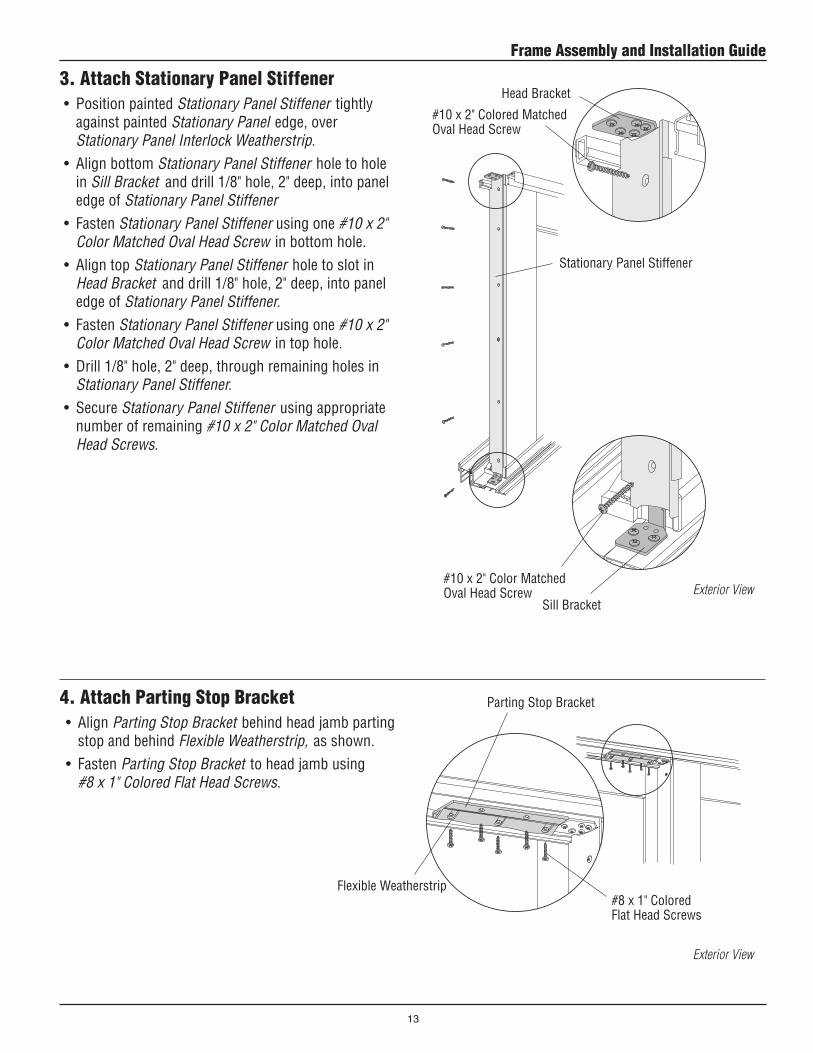
3. Attach Stationary Panel Stiffener• Position painted Stationary Panel Stiffener tightly
against painted Stationary Panel edge, over Stationary Panel Interlock Weatherstrip.
• Align bottom Stationary Panel Stiffener hole to hole in Sill Bracket and drill 1/8" hole, 2" deep, into panel edge of Stationary Panel Stiffener
• Fasten Stationary Panel Stiffener using one #10 x 2" Color Matched Oval Head Screw in bottom hole.
• Align top Stationary Panel Stiffener hole to slot in Head Bracket and drill 1/8" hole, 2" deep, into panel edge of Stationary Panel Stiffener.
• Fasten Stationary Panel Stiffener using one #10 x 2" Color Matched Oval Head Screw in top hole.
• Drill 1/8" hole, 2" deep, through remaining holes in Stationary Panel Stiffener.
• Secure Stationary Panel Stiffener using appropriate number of remaining #10 x 2" Color Matched Oval Head Screws.
Stationary Panel Stiffener
Head Bracket
#10 x 2" Colored Matched Oval Head Screw
Sill Bracket
#10 x 2" Color Matched Oval Head Screw Exterior View
4. Attach Parting Stop Bracket• Align Parting Stop Bracket behind head jamb parting
stop and behind Flexible Weatherstrip, as shown.• Fasten Parting Stop Bracket to head jamb using
#8 x 1" Colored Flat Head Screws.
Parting Stop Bracket
Flexible Weatherstrip#8 x 1" Colored Flat Head Screws
Exterior View
13
Frame Assembly and Installation Guide
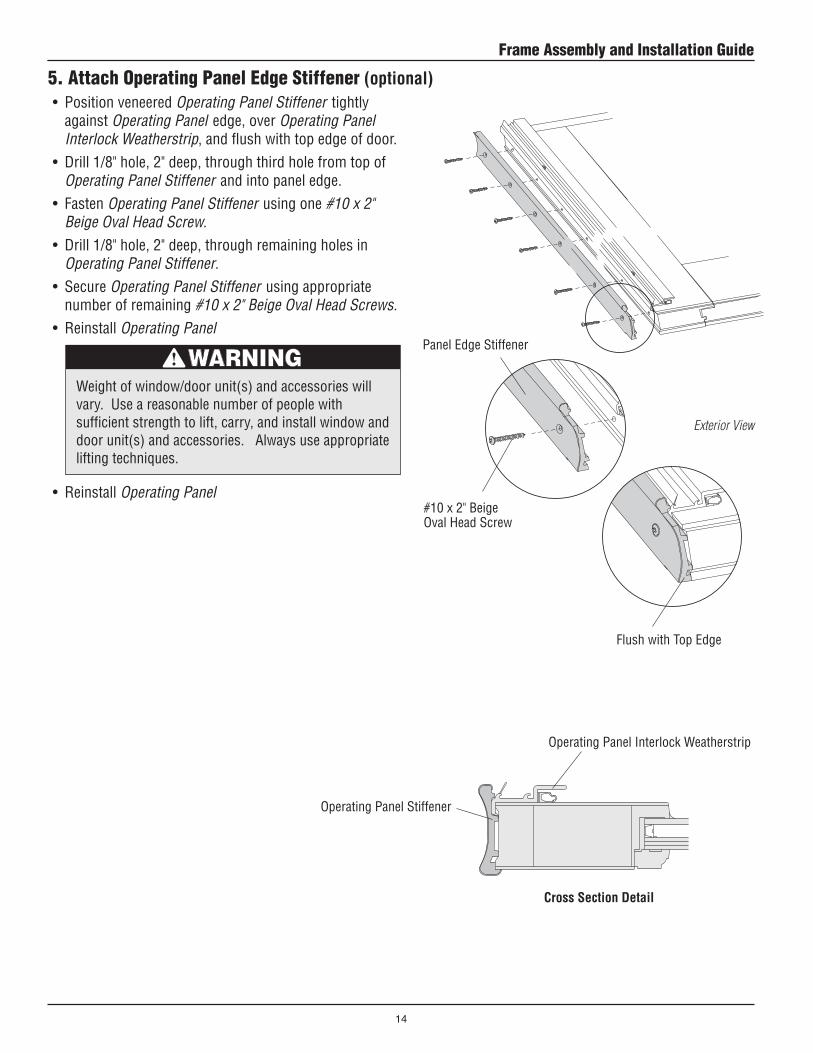
5. Attach Operating Panel Edge Stiffener (optional)• Position veneered Operating Panel Stiffener tightly
against Operating Panel edge, over Operating Panel Interlock Weatherstrip, and flush with top edge of door.
• Drill 1/8" hole, 2" deep, through third hole from top of Operating Panel Stiffener and into panel edge.
• Fasten Operating Panel Stiffener using one #10 x 2" Beige Oval Head Screw.
• Drill 1/8" hole, 2" deep, through remaining holes in Operating Panel Stiffener.
• Secure Operating Panel Stiffener using appropriate number of remaining #10 x 2" Beige Oval Head Screws.
• Reinstall Operating Panel Panel Edge Stiffener
#10 x 2" Beige Oval Head Screw
Operating Panel Interlock Weatherstrip
Operating Panel Stiffener
Exterior View
Flush with Top Edge
• Reinstall Operating Panel
Weight of window/door unit(s) and accessories will vary. Use a reasonable number of people with sufficient strength to lift, carry, and install window and door unit(s) and accessories. Always use appropriate lifting techniques.
Cross Section Detail
Frame Assembly and Installation Guide
14
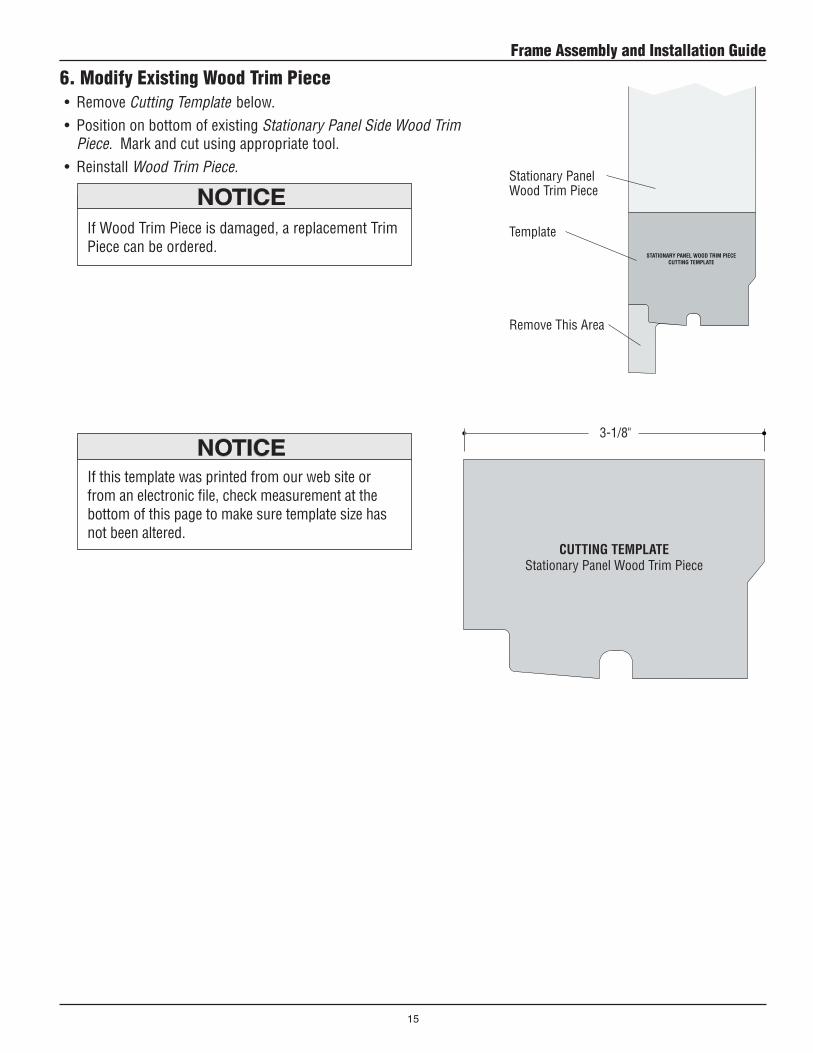
6. Modify Existing Wood Trim Piece• Remove Cutting Template below. • Position on bottom of existing Stationary Panel Side Wood Trim
Piece. Mark and cut using appropriate tool. • Reinstall Wood Trim Piece.
CUTTING TEMPLATE
Stationary Panel Wood Trim Piece
Stationary Panel Wood Trim Piece
Template
Remove This Area
3-1/8"
If this template was printed from our web site or from an electronic file, check measurement at the bottom of this page to make sure template size has not been altered.
If Wood Trim Piece is damaged, a replacement Trim Piece can be ordered.
15
Frame Assembly and Installation Guide
This page has been intentionally left blank.
Frame Assembly and Installation Guide
16