FPGA Based Adaptive Neuro Fuzzy Inference Controller for Full Vehicle Nonlinear Active Suspension...
15
International Journal of Artificial Intelligence & Applications (IJAIA), Vol.1, No.4, October 2010 DOI : 10.5121/ijaia.2010.1401 1 FPGA BASED ADAPTIVE NEURO FUZZY INFERENCE CONTROLLER FOR FULL VEHICLE NONLINEAR ACTIVE SUSPENSION SYSTEMS Ammar A. Aldair 1 and Weiji Wang 2 School of Engineering and Design, University of Sussex, Falmer, East Sussex Brighton, BN1 9QT, UK 1 [email protected] 2 [email protected] ABSTRACT A Field Programmable Gate Array (FPGA) is proposed to build an Adaptive Neuro Fuzzy Inference System (ANFIS) for controlling a full vehicle nonlinear active suspension system. A Very High speed integrated circuit Hardware Description Language (VHDL) has been used to implement the proposed controller. An optimal Fraction Order PI λ D μ (FOPID) controller is designed for a full vehicle nonlinear active suspension system. Evolutionary Algorithm (EA) has been applied to modify the five parameters of the FOPID controller (i.e. proportional constant K p , integral constant K i , derivative constant K d , integral order λ and derivative order μ). The data obtained from the FOPID controller are used as a reference to design the ANFIS model as a controller for the controlled system. A hybrid approach is introduced to train the ANFIS. A Matlab Program has been used to design and simulate the proposed controller. The ANFIS control parameters obtained from the Matlab program are used to write the VHDL codes. Hardware implementation of the FPGA is dependent on the configuration file obtained from the VHDL program. The experimental results have proved the efficiency and robustness of the hardware implementation for the proposed controller. It provides a novel technique to be used to design NF controller for full vehicle nonlinear active suspension systems with hydraulic actuators. KEYWORDS Full vehicle, Nonlinear Active Suspension System, Neuro-fuzzy Control, FPGA, Hardware Implementation. 1. INTRODUCTION The conventional controller like the PID controller requires an exact mathematical model of the controlled system to meet as much control objectives as possible. If it is difficult to establish the mathematical model for a system, the fuzzy logic controller is a good option to achieve a robust controller. Fuzzy logic systems, which can reason with imprecise information, are good at explaining their decisions but they cannot automatically acquire the rules used to make those decisions. On the other hand, artificial neural networks are good at recognizing patterns, and have ability to train the parameters of a control system, but they are not good at explaining how they reach their decisions. These limitations in both systems have brought about driving force behind the creation of intelligent hybrid systems (like Neuro-fuzzy system) where the two techniques are combined in a manner that the limitations of the individual techniques have been overcome. The neuro-adaptive learning techniques provide a method for the fuzzy modelling procedure to acquire information about a data set. This technique gives the fuzzy logic capability to compute the membership function parameters that effectively allow the associated fuzzy inference system to track the given input and output data. In order to process a fuzzy rule
-
Upload
independent -
Category
Documents
-
view
0 -
download
0
Transcript of FPGA Based Adaptive Neuro Fuzzy Inference Controller for Full Vehicle Nonlinear Active Suspension...
International Journal of Artificial Intelligence & Applications (IJAIA), Vol.1, No.4, October 2010
DOI : 10.5121/ijaia.2010.1401 1
FPGA BASED ADAPTIVE NEURO FUZZY
INFERENCE CONTROLLER FOR FULL VEHICLE
NONLINEAR ACTIVE SUSPENSION SYSTEMS
Ammar A. Aldair1 and Weiji Wang
2
School of Engineering and Design, University of Sussex, Falmer, East Sussex Brighton,
BN1 9QT, UK
ABSTRACT
A Field Programmable Gate Array (FPGA) is proposed to build an Adaptive Neuro Fuzzy Inference System
(ANFIS) for controlling a full vehicle nonlinear active suspension system. A Very High speed integrated
circuit Hardware Description Language (VHDL) has been used to implement the proposed controller. An
optimal Fraction Order PIλD
µ (FOPID) controller is designed for a full vehicle nonlinear active
suspension system. Evolutionary Algorithm (EA) has been applied to modify the five parameters of the
FOPID controller (i.e. proportional constant Kp, integral constant Ki, derivative constant Kd, integral
order λ and derivative order µ). The data obtained from the FOPID controller are used as a reference to
design the ANFIS model as a controller for the controlled system. A hybrid approach is introduced to train
the ANFIS. A Matlab Program has been used to design and simulate the proposed controller. The ANFIS
control parameters obtained from the Matlab program are used to write the VHDL codes. Hardware
implementation of the FPGA is dependent on the configuration file obtained from the VHDL program. The
experimental results have proved the efficiency and robustness of the hardware implementation for the
proposed controller. It provides a novel technique to be used to design NF controller for full vehicle
nonlinear active suspension systems with hydraulic actuators.
KEYWORDS
Full vehicle, Nonlinear Active Suspension System, Neuro-fuzzy Control, FPGA, Hardware Implementation.
1. INTRODUCTION
The conventional controller like the PID controller requires an exact mathematical model of the
controlled system to meet as much control objectives as possible. If it is difficult to establish
the mathematical model for a system, the fuzzy logic controller is a good option to achieve a
robust controller. Fuzzy logic systems, which can reason with imprecise information, are good
at explaining their decisions but they cannot automatically acquire the rules used to make those
decisions. On the other hand, artificial neural networks are good at recognizing patterns, and
have ability to train the parameters of a control system, but they are not good at explaining how
they reach their decisions. These limitations in both systems have brought about driving force
behind the creation of intelligent hybrid systems (like Neuro-fuzzy system) where the two
techniques are combined in a manner that the limitations of the individual techniques have been
overcome. The neuro-adaptive learning techniques provide a method for the fuzzy modelling
procedure to acquire information about a data set. This technique gives the fuzzy logic
capability to compute the membership function parameters that effectively allow the associated
fuzzy inference system to track the given input and output data. In order to process a fuzzy rule

International Journal of Artificial Intelligence & Applications (IJAIA), Vol.1, No.4, October 2010
2
by neural networks, it is necessary to modify the standard neural network structure accordingly.
In the last two decades, many researchers focused on the development of a hardware
implementation for both fuzzy logic controller and neural controller. [1], [2] and [3] used an
analogue circuit to implement each part of fuzzy system (including: Fuzzification, Fuzzy
Inference and Defuzzification). The structure of fuzzy system is complex, so that the analogue
circuit has to be very complicated to implement the logic system. Therefore, many researchers
proposed digital rather than analogue circuits to implement the fuzzy logic system.
Microprocessors or microcontrollers are popular in being used to implement fuzzy logic system
or neural network. Microprocessor based controllers are economical and flexible, but often face
difficulties in dealing with control systems. Therefore, higher density programmable logic
devices such as Programmable Logic Device (PLD) and Field Programmable Gate Array
(FPGA) have been developed to overcome the problems of microprocessors. The FPGA is
suitable for fast implementation and hardware verification. The control systems based on it are
flexible and can be reprogrammed with unlimited number of times. Many papers have reported
this technology to design Fuzzy Logic Controller (FLC) and Neural Controller (NC) for
different applications. Reference [4] developed software for synthesizing fuzzy controllers into
Boolean equations. Also, a hardware implementation of a fuzzy controller on the FPGA has
been described. The developed software together with the FPGA development system provides
a complete automation design tool for fuzzy controllers. Reference [5] presented an analysis
and performance evaluation of the proportional-derivative (PD) fuzzy logic controller designs
using Matlab and field programmable gate array. An embedded run-time reconfigurable
architecture for the design of a fuzzy logic PID controller is proposed in [6], [7] and [8].
Reference [9] presented and implemented a fuzzy controller on an FPGA using VHDL for a
motor unit. A Fuzzy controller has been implemented on the FPGA board to control a shunt
motor used for controlling the speed of electrical vehicle [10]. In Reference [11] simulation and
implementation of a fuzzy logic controller for a diesel driven stand-alone synchronous
generator have been designed. The controller was developed using VHDL and implemented in
FPGA. Reference [12] depicted a fuzzy logic model style based on two strategies: behavioral
modelling using VHDL and structural VHDL based on specific architecture of a fuzzy
processor. Reference [13] described the hardware implementation of fuzzy systems, a neural
networks and fuzzy neural networks using Xilinx FPGA.
The neuro-adaptive learning techniques provide a method for a fuzzy modelling procedure to
learn information about data sets. This technique gives the fuzzy logic capability to compute
the membership function parameters that best allow the associated fuzzy inference system to
track the given input and output data.
In this paper, an Adaptive Neuro-Fuzzy Inference System (ANFIS) based intelligent control for
full vehicle nonlinear active suspension system will be designed. The FOPID sub-controller
will be used to control the master controlled system. An Evolutionary Algorithm is proposed to
modify the control parameters of FOPID. The data obtained from the FOPID controller will be
used as a reference to train the parameters of the Neuro-fuzzy controller. The Simulink tool
boxes in Matlab will be used to simulate the controlled system (full vehicle nonlinear active
suspension system) with the proposed controller. The VHDL has been used to describe the
implementation of Neuro-fuzzy controller. In the FPGA based design, Xilinx ISE Project
Navigator Version 10.1 is used to obtain the compilation and timing test results as well as the
synthesized design. For the simulation results, ModelSim XE III 6.4b simulation program will
be used with the FPGA-based design. In order to compare the responses of the FPGA design
with the Simulink design, an M-file (Matlab-file) will be used to plot the data collected from
the ModelSim program and the other data collected form the Simulink design. These
comparisons will show that the responses of the FPGA design are similar to the responses of
the Simulink design.

International Journal of Artificial Intelligence & Applications (IJAIA), Vol.1, No.4, October 2010
3
2. MATHEMATICAL MODEL OF THE CONTROLLED SYSTEM
The main purposes of active suspension controller are to increase both riding comfort and
handling quality. The riding comfort can be measured by evaluating the acceleration and
displacement of sprung mass. The handling quality can be achieved by controlling the
rotational motions of the vehicle body such as rolling and pitch movements during cornering
and braking. Figure 1 illustrates the full vehicle nonlinear active suspension with hydraulic
actuators. In this model the tyres are modeled as linear spring in parallel with linear viscous
dampers. However, the suspension part is modeled as a nonlinear spring in parallel with a
nonlinear damper and a nonlinear hydraulic actuator. The nonlinear frictional forces due to
rubbing of piston seals with the cylinders wall inside the actuators are taken into account to
calculate the real supply forces generated by the hydraulic actuator
The following equations of motion are derived for the model using Newton laws of motion:
I. Vertical motion
According to
∑ ∑ ∑+−−== = =
4
1
4
1
4
1i i iPiCiKic FFFzM && (1)
where KiF and ��� are the nonlinear suspension spring force and nonlinear suspension damping
force, respectively, which can be written as [14]
3
)wz(K)wz(KF iiiiiiKi −ξ+−=
)wzsgn()wz(C)wz(CF iiiiiiiici&&&&&& −−ξ+−= 2
The force generated by hydraulic actuator can be written as
fiAiPi FFF −=
where FAi is the nonlinear hydraulic force provided by the ith actuator and Ffi the nonlinear
frictional force due to rubbing of piston seals with the cylinder wall inside the ith actuator. The
Figure 1. Full Vehicle Nonlinear Active Suspension

International Journal of Artificial Intelligence & Applications (IJAIA), Vol.1, No.4, October 2010
4
relation between the spool valve velocity, ���� , and the output force of this actuator, FAi = Ap PLi,
possess a nonlinear dynamic behaviour [15].
���� � � ��������������������� � ��� !� � �#�� �$� ��% (2)
The frictional force is modeled with a smooth approximation of Signum function:
<−
π−κ
>−−κ
=010
2010
010
.wzif.
wzsin
.wzif)wzsgn(
Fii
ii
iiii
fi&&
&&
&&&&
(3)
II. Pitching motion
xPPPP
CCCC
KKKKx
Tb
)FFFF(
b)FFFF(
b)FFFF(J
+−+−
++−−
++−−=α
2
2
2
2314
4321
4321&&
(4)
where b is the distance between the front wheels (or rear wheels).
III. Rolling motion
yPPPP
CCCC
KKKKy
Tl)FF(l)FF(
l)FF(l)FF(
l)FF(l)FF(J
++++
++−+
++−+=η
243121
121243
121243&&
(5)
where l1 is the distance between the centre of front wheel axle and centre of gravity of the
vehicle. l2 is the distance between the centre of gravity of the vehicle and the centre of rare wheel
axle.
The motion of the ith unsprung mass is governed by the following equation:
iPCiKiiiiiiiii FFFuwcuwkwm −++−−−−= )()( &&&& (6)
The experimental values for the above parameters are shown in Table 1.
3. FRACTIONAL-ORDER PIλDµ CONTROLLER
A fractional order differential equation is used to describe the fractional order PIλD
µ controller. In
PID controller case, three parameters Kp, Kd and Ki should be tuned to optimize the controller.
One of the possibilities to improve PID controllers is to use fractional-order controllers with a
real order of derivative and integral. The differential equation of fractional order controller can be
described by
[16]
)()()()( teDKteDKteKtu tdtipµλ ++= − (7)

International Journal of Artificial Intelligence & Applications (IJAIA), Vol.1, No.4, October 2010
5
where e(t) is the error between a measured process output variable and a desired set point and u(t)
is the control output. Eq. (7) shows that the FOPID controller needs to tune five parameters: Kp,
Ki, Kd, λ and µ. Therefore, the integral order and derivative order add more flexibility to design
an FOPID controller.
The continuous transfer function of the FOPID is given by
µλ
sKs
KK
sE
sUsG d
ipc ++==
)(
)()( (8)
The big challenge is how the optimal parameters of the FOPID controller can be chosen for
designing an accurate controller. An Evolutionary Algorithm has been used to serve this purpose.
Notation Description Values Units
K1, K2
Front-left and Front-right
suspension stuffiness,
respectively.
19960
N/m
K3, K4
Rear-right and rear-left
suspension stuffiness,
respectively.
17500
N/m
k1-k4
Front-left, Front-right, rear-
right and rear-left tire
stuffiness respectively.
175500
N/m
C1, C2
Front-left and Front-right
suspension damping,
respectively.
1290
N.sec/m
C3, C4
Rear-right and rear-left
suspension stuffiness,
respectively.
1620
N.sec/m
c1-c4
Front-left, Front-right, rear-
right and rear-left tire
damping, respectively.
14.6
N.sec/m
M Sprung mass. 1460 kg
m1, m2
Front-left, Front-right tire
mass, respectively.
40
kg
m3, m4
Rear-right and rear-left tire
mass, respectively.
35.5
kg
Jx Moment of inertia x-
direction.
460 kg.m2
Jy Moment of inertia y-
direction.
2460 kg.m2
l1
Distance between the center
of gravity of vehicle body
and front axle.
1.011
m
l2
Distance between the center
of gravity of vehicle body
and rear axle.
1.803
m
Table 1.Vehicle Suspension Parameters

International Journal of Artificial Intelligence & Applications (IJAIA), Vol.1, No.4, October 2010
6
4. THE STRUCTURE AND ITS TRAINING OF ADAPTIVE NEURO FUZZY
INFERENCE SYSTEM (ANFIS)
The ANFIS is one of the methods to organize the fuzzy inference system with given input-output
data pairs. The ANFIS is a combination of a fuzzy logic controller and a neural network, which
enables the controller self-tuning and adaptive. If these two intelligent techniques are combined,
it will achieve good reasoning in quality and quantity. This approach enables the fuzzy logic
capability to adapt the membership function parameters that best allow the associated fuzzy
inference system to track the given input and output data. The data obtained from the FOPID
controller will be use to modify the parameters of the ANFIS model. In order to process a fuzzy
rule by neural networks, it is necessary to modify the standard neural network structure
accordingly. Figure 2 depicts the structure of Neuro-fuzzy inference system (the type is called
Takagi-Sugeno-Kang [18]). For simplicity, the following assumptions will be made: (a) the
model has two inputs x and y and one output z, (b) it has just two rules (R1 and R2).
&1: )* � +, -./0 1 +, 2-345/ *- � 6-� 7 8-1+9-
&2: )*� +,;./01 +, 2-345/ *; � 6;� 7 8-1 7 9;
Figure 2. ANFS model structure
In Figure 2, the square nodes (adaptive nodes) have adaptable parameters while the circle nodes
(fixed nodes) have non-adaptable parameters. The function of each layer is described below:
A1
A2
B1
B2
Π
Π N
N
Σ
x
y
x y
x y
s1
s2
��=1
��=2
��=1��1
��=2��2 z
Layer 1 Layer 2 Layer 3 Layer 4 Layer 5
b Width of vehicle body 1.51 m
> Empirical parameter 0.1 -
?, A , B
Actuator parameters
4.515*1013
,1,
1.545*109
-
AP Cross section area of piston 3.35*10-4
m2
� Supply pressure 10342500 Pa
C Time constant 1/30 sec
Cd Discharge coefficient 0.7 -
ρ Fluid density 970
kg/m3
ω Area gradient 1.436e-2
m2

International Journal of Artificial Intelligence & Applications (IJAIA), Vol.1, No.4, October 2010
7
Layer 1: Every node I in this layer is a square node with a node function
D�- � µ���$� i=1, 2 (9)
where w is the input to the node i (x or y) and Ai is the linguistic label associated with this node.
µ���$� has been chosen as bell shape membership function:
µ���$� �1
1 7 �E$ � F�.� G;%H�
where {.�, I�, F�J are the parameters of membership function (they are called premise parameters)
which will be modified in the training phase.
Layer 2: Every node in this layer is a circle node (has non-adaptable parameters) labeled Π which
multiplies the incoming signals. The output of each node in this layer can be written as:
D�; � ,� � µ����� X µL��1� i=1, 2 (10)
Layer 3: Every node in this layer is a circle node labeled N. the output of ith
node is the
normalized of the ith rule’s firing strength. The output of any node in this layer can be given as
D�M � ,=� � ���NO�P (11)
Layer 4: Every node in this layer is square node with a linear function
*� � 6�� 7 8�1 7 9� (12)
where {6� , 8�, 9�J is the set parameters called consequent parameters of linear equation which will
be modified in the training phase. The output of any nodes in this layer can be written as:
D�Q � ,=�*� � ,=��6�� 7 8�1 7 9�� (13)
Layer 5: the node in this layer is circle node labeled Σ that computes the overall output as the
summation of all incoming signals
# � D�R � ∑ ,=�*� � ∑ ��T��∑ ���� . (14)
The adaptable parameters of the ANFIS {.� , I�, F� , 6� , 8�, 9�J should be modified to minimize the
following performance function:
U � ∑ U�V- (15)
where P is the total number of training data set and Ep the error signal between the desired output
of pth data and the actual output of the ANFIS model of p
th data. Ep can be given by
U � W � # (16)

International Journal of Artificial Intelligence & Applications (IJAIA), Vol.1, No.4, October 2010
8
where Tp is the pth desired output and zp is the p
th actual output in the ANFIS model.
To modify the parameters of the ANFIS model, the steepest descent method as in neural network
can be applied to modify the premise parameters {.� , I�, F�J and least square estimate can be
applied to adapt the consequent parameters {6�, 8�, 9�J [19].
5. HARDWARE DESCRIPTION OF ANFIS
The VHDL codes have been developed to describe the ANFIS model controller. The optimal
values of the premise parameters and the consequent parameters have been used to write the
VHDL codes. Xilinx ISE 10.1 has been used as programming environment to write these codes.
To generate a configuration file used to program the FPGA board, the flowing steps should be
followed:
i. Create the design project and VHDL codes,
ii. Create a testbench and perform RTL simulation,
iii. Add a constraint file then synthesize and implement the codes.
After downloading the configuration file on to the FPGA chip (XILINX Spartan XC3S700AN)
the FPGA board will be ready to use as ANFIS controller for the controlled system. The Spartan
3E starter Kit board highlights the unique features of the Spartan_3E FPGA family and provides a
convenient development board for embedded processing applications. The Hirose 100-pin FX2
Edge connector (J3) will be used as input and output port to receive the digital input data (error
and error rate) from the A/D converter (error signal is the difference between the output of the
controlled system and desired output) and send the digital control signal to the D/A converter
(analogue control signal will be used to force the output of the controlled system to follow the
desired output).
6. SIMULATION AND RESULTS
The active suspension is presented in order to reduce the discomfort arising from road roughness
and to improve the handling quality. This necessitates a very fast and accurate controller to meet
as much control objectives as possible. Furthermore, the controlled system has very complex
nonlinear model as shown in Section 2. Therefore, an intelligent Neuro fuzzy controller has been
proposed to meet the control objectives. An Evolutionary Algorithm has been applied to modify
the five parameters (proportional constant Kp, integral constant Ki, derivative constant Kd, integral
order λ and derivative order µ) of each FOPID controller. Figures 3, 4, 5, 6 and 7 show the
changing of the control parameters during the optimization process. After 225 optimization
iteration steps, the optimal values of the FOPID controller parameters can be obtained as shown
in Table 2. During optimization phase, it is assumed that the inputs to the full vehicle model are
just the road uneven excitation and control forces. The white noise input is supplied as road
profile.

International Journal of Artificial Intelligence & Applications (IJAIA), Vol.1, No.4, October 2010
9
Figure 3. Changing value of Kp during optimization steps Figure 4. Changing value of Kd during optimization steps
Figure 5. Changing value of Ki during optimization steps Figure 6. Changing value of λ during optimization steps
Table 2. Initial and optimal values of FOPID controller
Figure 7. Changing value of µ during optimization steps
Parameter Initial value Optimal
value
KP 100 12678.26
Kd 20 3253.92
Ki 1 768.1
λλλλ 0.3 0.45
µµµµ 0.7 0.886

International Journal of Artificial Intelligence & Applications (IJAIA), Vol.1, No.4, October 2010
10
The hybrid learning algorithm has been used to modify the ANFIS (premise and consequent)
parameters to track the input and output data obtained from FOPID controller. Four NF
controllers have been designed (one for each suspension).
To establish the effectiveness of the proposed controller the robustness should be examined. Four
types of disturbances are applied in turn to check the robustness of the NF controller as described
below.
• Square input signal with varying amplitude applied as road input profile
The square input signal has been applied as road input. The amplitude of this signal has been
changed from 0.01m to 0.1m. At each value the cost function (as described in Equation 17) has
been calculated:
∑=ε
ε=φ4
1
2z5.0 (17)
Figure 8 shows the time response of the cost function as function of amplitude of square signal
input.
• Sine wave input signal with varying amplitude applied as road input profile
The different amplitude of sine wave input from 0.01m to 0.1m has been applied as road
profile input. The time response of the cost function for the full vehicle without controller, the
result of the FOPID controller and NF controller are shown together in Figure 9 (where the scale
of the y-axis is the log scale).
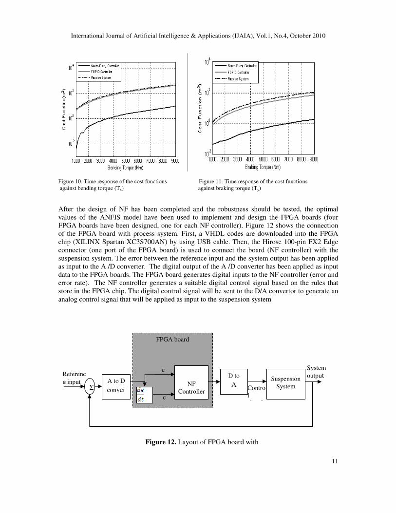
• Bending inertia Torque (Tx) applied
The value of bending torque (from 1000 Nm to 9000Nm) in addition to random signal as road
profile has been applied. The cost function response is plotted as function of Tx in Figure 10.
• Breaking inertia Torque (Ty) applied
The value of breaking torque (from 1000 Nm to 9000Nm) in addition to random signal as road
profile has been applied. The cost function response is plotted as function of Ty in Figure 11.
Figure 8. Time response of the cost functions against Figure 9. Time response of the cost functions against
the different amplitude of square input the different amplitude of sine wave input.
International Journal of Artificial Intelligence & Applications (IJAIA), Vol.1, No.4, October 2010
11
Figure 10. Time response of the cost functions Figure 11. Time response of the cost functions
against bending torque (Tx) against braking torque (Ty)
After the design of NF has been completed and the robustness should be tested, the optimal
values of the ANFIS model have been used to implement and design the FPGA boards (four
FPGA boards have been designed, one for each NF controller). Figure 12 shows the connection
of the FPGA board with process system. First, a VHDL codes are downloaded into the FPGA
chip (XILINX Spartan XC3S700AN) by using USB cable. Then, the Hirose 100-pin FX2 Edge
connector (one port of the FPGA board) is used to connect the board (NF controller) with the
suspension system. The error between the reference input and the system output has been applied
as input to the A /D converter. The digital output of the A /D converter has been applied as input
data to the FPGA boards. The FPGA board generates digital inputs to the NF controller (error and
error rate). The NF controller generates a suitable digital control signal based on the rules that
store in the FPGA chip. The digital control signal will be sent to the D/A convertor to generate an
analog control signal that will be applied as input to the suspension system
Figure 12. Layout of FPGA board with
FPGA board
NF
Controller
D to
A
conve
Suspension
System Σ A to D
conver
ter
Referenc
e input
System
output e
c
Contro
l
signal

International Journal of Artificial Intelligence & Applications (IJAIA), Vol.1, No.4, October 2010
12
A test is performed to make sure that the NF controller used inside the FPGA-based design
functions properly. The ModelSim XE III 6.4b program has been used to simulate the outputs of
FPGA boards before using them as control systems for the suspension unit. The control signals,
which have obtained form the simulation program (ModelSim XE III 6.4b), have been compared
with the control signals which have obtained from Simulink design using Matlab Program.
Figures 13-16 show the control signals obtained from each design (Simulation design and
hardware design) for each controller
Figure 13. The control signal for first controller of Figure 14. The control signal for second controller of
(a).Simulation design. (b) Hardware design (a).Simulation design. (b) Hardware design

International Journal of Artificial Intelligence & Applications (IJAIA), Vol.1, No.4, October 2010
13
Figure 15. The control signal for control three of Figure 16. The control signal for control three of
(a).Simulation design. (b).Hardware design (a).Simulation design. (b) .Hardware design
7. CONCLUSIONS
The main objectives of designed the controller for a vehicle suspension system are to reduce the
discomfort felt by passengers which arises from road roughness and to increase the ride handling
associated with the pitching and rolling movements. In this paper, an ANFIS model has used to
design the control system for full vehicle nonlinear active suspension system. The results have
been compared with the performances of the FOPID controller and the NF controller in the case
sudden disentrances occur. The proposed controller improves the vertical displacements at each
corner of the vehicle to reach low level. It means that the ride comfort and the road handling have
been improved. It has been confirmed that the proposed controller is more robust and more
effective than the Fractional Order PIλD
µ (FOPID) controller. It provides a novel technique to be
used to design NF controller for full vehicle nonlinear active suspension systems with hydraulic
actuators. The optimal parameters of the NF controller have been used to design the controller
hardware using the FPGA board. The results show that the control signals obtained from the
FPGA boards are identical to the control signals which are obtained from design simulation. The
results are encouraging and have proved the effectiveness both algorithm and hardware
architecture. Therefore, the FPGA boards are effective to be used to control the full vehicle
nonlinear active suspension systems with hydraulic actuators.

International Journal of Artificial Intelligence & Applications (IJAIA), Vol.1, No.4, October 2010
14
REFERENCES
[1] Gilbert, B., A monolithic 16-channel Analog arry Normalizer. IEEE Journal of solid state circuits,
1984. 19(6): p. 956-963.
[2] Ishizuka, O., et al., Design of a Fuzzy Controller With Normalization Circuits. IEEE International
Conference on Digital Objective Identifier, 1992: p. 1303-1308.
[3] Yamakawa, T., A Fuzzy Programmable Logic Array (Fuzzy PLA). IEEE International Conference
on Digital Objective Identifier, 1992: p. 459-465.
[4] Manzoul, M.A. and D. Jayabharathi, FUZZY CONTROLLER ON FPGA CHIP. IEEE
International Conference on Digital Objective Identifier, 1992: p. 1309-1316.
[5] Obaid, Z.A., et al., Analysis and Performance Evaluation of PD-like Fuzzy Logic Controller
Design Based on Matlab and FPGA International Journal of Computer Science, 2010. 37(2).
[6] Economakos, G. and C. Economakos, A Run-Time Recongurable Fuzzy PID Controller Based on
Modern FPGA Devices. Mediterranean Conference on Control and Automation, 2007: p. 1-6.
[7] Tipsuwanpornm, V., et al., Fuzzy Logic PID controller based on FPGA for process control. IEEE
International Syposium on Industrial Electronics, 2004. 2: p. 1495-1500.
[8] Hu, B.S. and J. Li, The Fuzzy PID Gain Conditioner: Algorithm, Architecture and FPGA
Implementation. IEEE International Conference on Industrial Technology, 1996: p. 621-624.
[9] Singh, B., et al., Design and VLSI implementation of Fuzzy Logic Controller International Journal
of Computer and Network Security, 2009. 1(3).
[10] S.Poorani, et al., FPGA BASED FUZZY LOGIC CONTROLLER FOR ELECTRIC VEHICLE.
Journal of The Institution of Engineers, 2005. 45(5): p. 1- 14.
[11] Cirstea, M., J. Khor, and M. McCormick, FPGA Fuzzy Logic Controller for Variable Speed
Generator. IEEE International Conference on Control Application, 2001: p. 5-7.
[12 Barriga, A., et al., Modelling and implementation of fuzzy systems based on VHDL. International
Journal of Approximate Reasoning, 2006. 41: p. 164-178.
[13] Blake, J.J., et al., The implementation of fuzzy systems, neural networks and fuzzy neural
networks using FPGAs Information Science, 1998. 112: p. 151-168.
[14] Ando, Y. and M. Suzuki, Control of Active Suspension Systems Using the Singular Perturbation
method. Control Engineering Practice, 1996. 4(33): p. 287-293.
[15] Merritt, H., Hydraulic Control Systems. 1969, USA: John wiley and Sons,Inc.
[16] xue, D., Y. Chen, and D. Atherton, Linear Feedback Controller Analysis and Design with
MATLABE. 2007, USA: The Society for Industrial and Applied Mathematics.
[17] Back, T., Evolutionary Algorithms in Theory and Practice. 1996, London, UK: Oxford University
Press.
[18] Nguyen, H.T., et al., A First Course in Fuzzy and Neural Control. 2003, USA: Chapman & Hall/
CRC.
[19] Jang, J.-S.R., ANFIS: Adaptive Network Based Fuzzy Inference System. IEEE Transaction on
System, Man and Cybernetics 1993. 23(3): p. 665-686.

International Journal of Artificial Intelligence & Applications (IJAIA), Vol.1, No.4, October 2010
15
Authors
Ammar Aldair was born in Basrah, Iraq. He received his B.Sc. Degree in
Electrical Engineering from University of Basrah, Iraq in 2000. In 2003, he
received his M.Sc. Degree in Control and Systems Engineering from University
of Basrah, Iraq. From 2003-2008, he was a Lecturer in Electrical Department,
University of Basrah, Iraq. He taught many subjects such as: Mathematics, Logic
Systems, Electrical Circuits, Electronic Circuits, Control Systems and Advance
Control systems. In 2008, he had a scholarship from Iraqi government to get the
DPhil Degree in Intelligent Control Systems from UK. Currently, he is a DPhil
student in School of Engineering and Design, University of Sussex, UK. His
current research interests in Intelligent Control Systems.
Weiji Wang was born in China. He received his DPhil degree from Oxford
University in 1993. Currently he is a senior lecturer in School of Engineering and
Design, University of Sussex. His current research interests in Automotive
Dynamics and Control.