Formation of subwavelength grating on molybdenum mirrors using a femtosecond Ti:sapphire laser...
7
REVIEW OF SCIENTIFIC INSTRUMENTS 82, 033113 (2011) Formation of subwavelength grating on molybdenum mirrors using a femtosecond Ti:sapphire laser system operating at 10 Hz Avnish Kumar Sharma, 1,2, a) John Smedley, 1 Thomas Tsang, 1 and Triveni Rao 1 1 Instrumentation Division, Brookhaven National Laboratory, Upton, New York 11973, USA 2 Laser Plasma Division, Raja Ramanna Centre for Advanced Technology, Indore 452013, MP, India (Received 20 June 2010; accepted 27 February 2011; published online 29 March 2011) We report formation of subwavelength surface grating over large surface area of molybdenum mir- ror by multiple irradiation of amplified femtosecond laser pulses from a homemade Ti:sapphire oscillator–amplifier laser system in a raster scan configuration. The laser system delivered 2 mJ, 80 fs duration laser pulses at a pulse repetition rate of 10 Hz. Various parameters such as pulse flu- ence, number of pulses, laser polarization, scan speed, and scan steps were optimized to obtain uni- form subwavelength gratings. Energy dispersive x-ray spectroscopy measurements were conducted to analyze the elemental composition of mirror surfaces before and after laser treatment. © 2011 American Institute of Physics. [doi:10.1063/1.3569763] I. INTRODUCTION There has been a great interest in laser material pro- cessing using intense femtosecond laser pulses. Femtosec- ond laser ablation is a promising technology for surface nanostructuring of variety of materials such as metals, 1–8 semiconductors, 9, 10 and dielectrics. 11 Direct, repetitive fem- tosecond laser exposure leads to the formation of laser- induced periodic surface structures (LIPSSs). Surface modifi- cation via repetitive irradiation with femtosecond laser pulse is one of the important areas of research for modification of optical properties (e.g., modifying the reflectivity, absorp- tion, etc.) and also useful for basic understanding of phys- ical mechanism involved, for instance, how the LIPSSs are formed and what are the factors responsible for their forma- tion. The applications of the surface modification include fab- rication of efficient wide spectral range photodetectors, 9, 10 brighter incandescent light sources, 12 nanograting surface plasmon resonance sensors, 13 and fabrication of novel optical components, 14 etc. Next, the surface morphological character- istic of LIPSSs resembles the grating fabricated by advanced nanofabrication techniques. Therefore, fabricating a surface nanograting via LIPSSs formation is quite simple and easy compared to other nanofabrication techniques. Detailed investigations on laser-induced periodic surface structures formation have been carried on several metals such as platinum, 1 tungsten, 2 silver, 3 gold, 4 aluminum, 5 copper, 6 NiTi alloy, 7 stainless steel, 8 etc. In above studies, low spa- tial frequency LIPSSs with periodic spacing comparable to laser wavelength has been observed and explained on the basis of classical theory of interference. High spatial fre- quency LIPSSs, where periodic spacing of LIPSSs is much smaller than wavelength of incident radiation, is observed in dielectrics, semiconductors, and also on few metal surfaces such as copper 6 and stainless steel. 8 While the process behind the formation of high frequency LIPSS is still under investi- gation, surface plasmons are suggested to be responsible for LIPSSs formation on the metal surfaces. However, LIPSSs a) Electronic mail: [email protected]. were formed on tungsten mirror surface, 2 which does not sup- port surface plasmon at room temperature. Next, LIPSSs were predominately formed using incident laser polarization par- allel to the scan direction. Molybdenum is a very important class of material and may be useful in applications such as low emittance photoinjector by modifying its surface optical properties using multiple femtosecond pulse irradiation. Like tungsten, the molybdenum mirror also does not support sur- face plasmons (SPs) at room temperature. It is interesting to study the formation of LIPSSs on molybdenum mirror sur- face and compare the results with those obtained in the case of tungsten. In this article, we report a chirped pulse amplification (CPA) based Ti:sapphire laser system which generates 2 mJ, 80 fs duration laser pulses (peak wavelength 810 nm) at a repetition rate of 10 Hz and its application to create subwave- length surface grating on molybdenum mirror via LIPSSs formation. The subwavelength surface gratings were formed over large surface area of molybdenum mirror surfaces us- ing raster scanning and optimizing laser pulse fluence, num- ber of pulses, laser polarization, scan speed, and scan step. We observed that formation of LIPSSs was insensitive to scan direction relative to laser polarization. To carry out elemen- tal analysis of smooth and nanostructured mirror surfaces, energy dispersive x-ray spectroscopic (EDS) measurements were conducted. II. BRIEF DESCRIPTION OF THE LASER SYSTEM The chirped pulse amplification 15 based laser system in- volves ultrashort laser pulse temporal stretching, amplifica- tion, and then recompression of the amplified pulses. The present laser system includes a home-built cw mode-locked laser oscillator, providing sub-20 fs laser pulses at 89 MHz repetition rate, an all-reflective grating (1200 lines/mm, groove density) based double-pass pulse stretcher, commer- cial acousto-optic programmable dispersive filter and a single pulse selector at 10 Hz, 12-pass Ti:sapphire amplifier pumped by Q-switched Nd:YAG laser (Spectra Physics) operating at 0034-6748/2011/82(3)/033113/7/$30.00 © 2011 American Institute of Physics 82, 033113-1
-
Upload
independent -
Category
Documents
-
view
1 -
download
0
Transcript of Formation of subwavelength grating on molybdenum mirrors using a femtosecond Ti:sapphire laser...
REVIEW OF SCIENTIFIC INSTRUMENTS 82, 033113 (2011)
Formation of subwavelength grating on molybdenum mirrors usinga femtosecond Ti:sapphire laser system operating at 10 Hz
Avnish Kumar Sharma,1,2,a) John Smedley,1 Thomas Tsang,1 and Triveni Rao1
1Instrumentation Division, Brookhaven National Laboratory, Upton, New York 11973, USA2Laser Plasma Division, Raja Ramanna Centre for Advanced Technology, Indore 452013, MP, India
(Received 20 June 2010; accepted 27 February 2011; published online 29 March 2011)
We report formation of subwavelength surface grating over large surface area of molybdenum mir-ror by multiple irradiation of amplified femtosecond laser pulses from a homemade Ti:sapphireoscillator–amplifier laser system in a raster scan configuration. The laser system delivered 2 mJ,80 fs duration laser pulses at a pulse repetition rate of 10 Hz. Various parameters such as pulse flu-ence, number of pulses, laser polarization, scan speed, and scan steps were optimized to obtain uni-form subwavelength gratings. Energy dispersive x-ray spectroscopy measurements were conductedto analyze the elemental composition of mirror surfaces before and after laser treatment. © 2011American Institute of Physics. [doi:10.1063/1.3569763]
I. INTRODUCTION
There has been a great interest in laser material pro-cessing using intense femtosecond laser pulses. Femtosec-ond laser ablation is a promising technology for surfacenanostructuring of variety of materials such as metals,1–8
semiconductors,9, 10 and dielectrics.11 Direct, repetitive fem-tosecond laser exposure leads to the formation of laser-induced periodic surface structures (LIPSSs). Surface modifi-cation via repetitive irradiation with femtosecond laser pulseis one of the important areas of research for modificationof optical properties (e.g., modifying the reflectivity, absorp-tion, etc.) and also useful for basic understanding of phys-ical mechanism involved, for instance, how the LIPSSs areformed and what are the factors responsible for their forma-tion. The applications of the surface modification include fab-rication of efficient wide spectral range photodetectors,9, 10
brighter incandescent light sources,12 nanograting surfaceplasmon resonance sensors,13 and fabrication of novel opticalcomponents,14 etc. Next, the surface morphological character-istic of LIPSSs resembles the grating fabricated by advancednanofabrication techniques. Therefore, fabricating a surfacenanograting via LIPSSs formation is quite simple and easycompared to other nanofabrication techniques.
Detailed investigations on laser-induced periodic surfacestructures formation have been carried on several metals suchas platinum,1 tungsten,2 silver,3 gold,4 aluminum,5 copper,6
NiTi alloy,7 stainless steel,8 etc. In above studies, low spa-tial frequency LIPSSs with periodic spacing comparable tolaser wavelength has been observed and explained on thebasis of classical theory of interference. High spatial fre-quency LIPSSs, where periodic spacing of LIPSSs is muchsmaller than wavelength of incident radiation, is observed indielectrics, semiconductors, and also on few metal surfacessuch as copper6 and stainless steel.8 While the process behindthe formation of high frequency LIPSS is still under investi-gation, surface plasmons are suggested to be responsible forLIPSSs formation on the metal surfaces. However, LIPSSs
a)Electronic mail: [email protected].
were formed on tungsten mirror surface,2 which does not sup-port surface plasmon at room temperature. Next, LIPSSs werepredominately formed using incident laser polarization par-allel to the scan direction. Molybdenum is a very importantclass of material and may be useful in applications such aslow emittance photoinjector by modifying its surface opticalproperties using multiple femtosecond pulse irradiation. Liketungsten, the molybdenum mirror also does not support sur-face plasmons (SPs) at room temperature. It is interesting tostudy the formation of LIPSSs on molybdenum mirror sur-face and compare the results with those obtained in the caseof tungsten.
In this article, we report a chirped pulse amplification(CPA) based Ti:sapphire laser system which generates 2 mJ,80 fs duration laser pulses (peak wavelength 810 nm) at arepetition rate of 10 Hz and its application to create subwave-length surface grating on molybdenum mirror via LIPSSsformation. The subwavelength surface gratings were formedover large surface area of molybdenum mirror surfaces us-ing raster scanning and optimizing laser pulse fluence, num-ber of pulses, laser polarization, scan speed, and scan step.We observed that formation of LIPSSs was insensitive to scandirection relative to laser polarization. To carry out elemen-tal analysis of smooth and nanostructured mirror surfaces,energy dispersive x-ray spectroscopic (EDS) measurementswere conducted.
II. BRIEF DESCRIPTION OF THE LASER SYSTEM
The chirped pulse amplification15 based laser system in-volves ultrashort laser pulse temporal stretching, amplifica-tion, and then recompression of the amplified pulses. Thepresent laser system includes a home-built cw mode-lockedlaser oscillator, providing sub-20 fs laser pulses at 89 MHzrepetition rate, an all-reflective grating (1200 lines/mm,groove density) based double-pass pulse stretcher, commer-cial acousto-optic programmable dispersive filter and a singlepulse selector at 10 Hz, 12-pass Ti:sapphire amplifier pumpedby Q-switched Nd:YAG laser (Spectra Physics) operating at
0034-6748/2011/82(3)/033113/7/$30.00 © 2011 American Institute of Physics82, 033113-1
033113-2 Sharma et al. Rev. Sci. Instrum. 82, 033113 (2011)
10 Hz pulse repetition rate, laser beam optics, and finally agrating pair (1200 lines/mm, groove density) based double-pass pulse compressor. The laser pulses were temporally char-acterized using home-built tilted pulse-front autocorrelator16
and a commercial second harmonic generation based fre-quency resolved optical gating setup. The spatial and spectraldomain measurements were carried out using a CCD camera(model DataRay WinCamD) and a high-resolution miniaturespectrometer (ocean optics HR 2000), respectively. The lasersystem delivers 80 fs duration laser pulses with pulse energyof 2 mJ at a repetition rate of 10 Hz.
To amplify stretched laser pulses from subnano joule tofew milli joule energy level, multipass amplifier instead ofregenerative amplifier has been chosen to avoid the use ofadditional electro-optics and simultaneously minimizing ac-cumulated material dispersion and spectral-gain narrowing.Laser pulse amplification in a multipass amplifier is generallyachieved by placing the gain medium at the focal position ofthe focusing and collimating mirrors with equal focal lengths(i.e., symmetric confocal geometry17, 18). The extractionefficiency of such geometry is limited to 1%–3%. An asym-metric confocal geometry19–21 involving use of mirrors withunequal focal lengths has been demonstrated to improve theextraction efficiency of the amplifier. We have used an asym-metric amplifier geometry formed by four mirrors each hav-ing focal lengths of 50 cm, but the Ti:sapphire crystal wasplaced slightly asymmetrically (45 cm from pulse injectingconcave mirror). With this asymmetric arrangement in po-sition of the gain medium, the output pulse energy after12 passes is obtained to be ∼3 mJ at pump pulse energy of∼25 mJ; thus, an overall gain and extraction efficiency of 5× 10⁶ and 12%, respectively. The observed extraction effi-ciency is larger than that typically achieved in a confocal ge-ometry and compares well with that obtained with asymmet-ric confocal amplifier19, 20 or double confocal amplifier.21
The required synchronization22 between laser oscillator,Nd:YAG pump laser and other subsystems is achieved using acommercial digital delay generator only to reduce the cost andcomplexity of the laser system in following way. The low fre-quency synchronized trigger signals with required temporaldelays are generated by setting the delay to one of the out-put channel (D) of digital delay generator (Stanford DG535)slightly smaller than the time period (1/ftr) of the desired trig-ger rate (ftr). Thus, to obtain trigger signals at 10 Hz, the de-lay to D output of DG535 is set at 99.9 ms. Once digital de-lay generator is triggered by one of laser pulses of the pulsetrain, it ignores rest of trigger pulses till the D set delay is overand then retrigger occurs; thus, effectively generating low fre-quency synchronized trigger signals. The minimum and maxi-mum trigger rate can be 1 mHz and 1 MHz and is determinedby the longest allowed delay and minimum cycling time ofthe delay generator, respectively. The digital delay generatorwas triggered directly by amplified photodiode signal (using300 MHz amplifier—Stanford SR440), which is derived byirradiating the reflected laser beam from pulse stretcher’s firstgrating on to a fast (rise time <300 ps) silicon detector. Thedelay outputs namely To, A, B, and C from the delay genera-tor are then used to trigger the dazzler, firing the flash lamps,Q-switch, and activating the pulse picker, respectively.
III. SUBWAVELENGTH GRATING FORMATIONON MIRROR SURFACE
In order to study the formation of subwavelength gratingon polished molybdenum mirror (20MO5–00 from ULO op-tics) surface, the sample was mounted vertically on a com-puter controlled XYZ translation stage. The stage can bemoved continuously in the horizontal direction and in stepsin the vertical direction to raster scan the mirror surface. Thescan rate and step size can be varied by changing the com-puter program setting. A 20 cm focal length, plano-convexlens was used to focus the laser beam onto the mirror sam-ple. The sample was irradiated repetitively with 1 mJ, 100 fslaser pulses at near normal incidence. The mirror surface wasanalyzed under optical microscope (Olympus BH2) and un-der scanning electron microscope (JEOL-JSM-6500F) imme-diately before and after laser treatment and after ultrasoniccleaning for about 1 h. The dependence of the surface mod-ification on pulse fluence, number of pulses, scan speed, andlaser polarization were investigated. These parameters wereoptimized to form uniform subwavelength LIPSSs on the mir-ror surface.
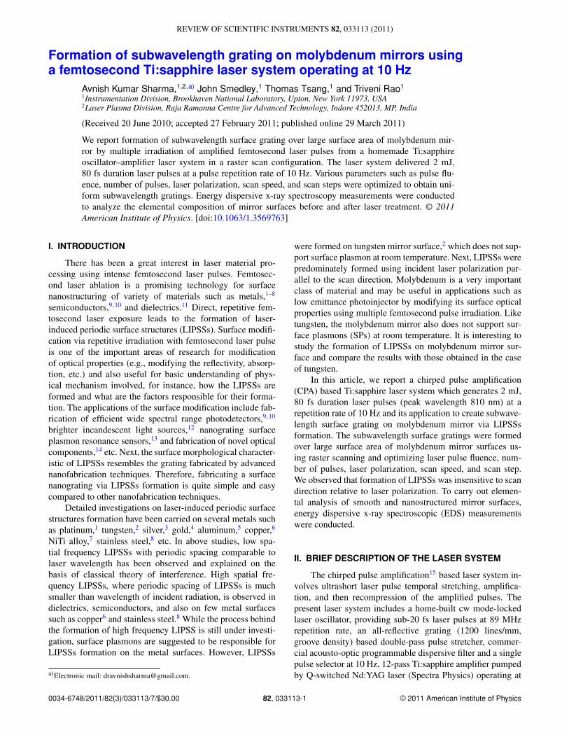
Figure 1 depicts scanning electron microscope (SEM)images of untreated mirror surface (no laser exposure) andmirror surface exposed to multiple laser pulses at fluence of∼0.5 J/cm2 for a scan speed of 0.01 mm/s and a vertical scanstep of 10 μm between two scans under two different mag-nifications. The SEM image of treated mirror surface afterultrasonic cleaning for about 1 h just after the laser treat-ment is also given in Fig. 1. The laser beam was linearlypolarized and orientation of polarization was along the scandirection. The morphology of the observed periodic nanos-tructure (i.e., LIPSSs) resembles a uniform subwavelengthsurface grating with period of ∼650 nm. The orientation ofgrooves of the grating is observed to be perpendicular to theorientation of laser polarization. The periodic spacing may beexplained with the classical theory of interference for LIPSSsformation.23, 24
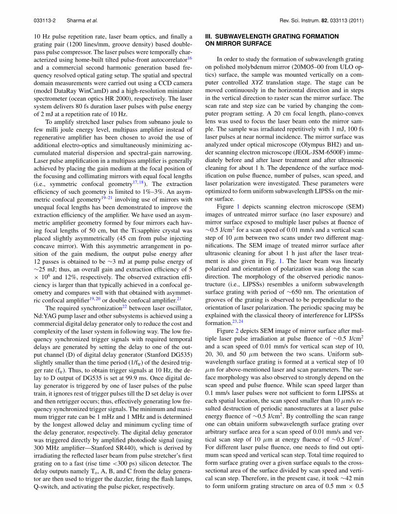
Figure 2 depicts SEM image of mirror surface after mul-tiple laser pulse irradiation at pulse fluence of ∼0.5 J/cm2
and a scan speed of 0.01 mm/s for vertical scan step of 10,20, 30, and 50 μm between the two scans. Uniform sub-wavelength surface grating is formed at a vertical step of 10μm for above-mentioned laser and scan parameters. The sur-face morphology was also observed to strongly depend on thescan speed and pulse fluence. While scan speed larger than0.1 mm/s laser pulses were not sufficient to form LIPSSs ateach spatial location, the scan speed smaller than 10 μm/s re-sulted destruction of periodic nanostructures at a laser pulseenergy fluence of ∼0.5 J/cm2. By controlling the scan rangeone can obtain uniform subwavelength surface grating overarbitrary surface area for a scan speed of 0.01 mm/s and ver-tical scan step of 10 μm at energy fluence of ∼0.5 J/cm2.For different laser pulse fluence, one needs to find out opti-mum scan speed and vertical scan step. Total time required toform surface grating over a given surface equals to the cross-sectional area of the surface divided by scan speed and verti-cal scan step. Therefore, in the present case, it took ∼42 minto form uniform grating structure on area of 0.5 mm × 0.5
033113-3 Sharma et al. Rev. Sci. Instrum. 82, 033113 (2011)
FIG. 1. Typical SEM image of molybdenum mirror surface: (a) untreated mirror surface; (b) treated mirror surface with multiple femtosecond pulse irradiationat fluence of ∼0.5 J/cm2 for a scan speed of 0.01mm/s and vertical scan step of 10 μm; (c) treated mirror surface after ∼1 h ultrasonic cleaning. Photographsshown in (d)–(f) are SEM images corresponding to (a)–(c), respectively, recorded under higher magnification. The laser polarization orientation is perpendicularto the observed LIPSSs and is parallel to the scan direction.
mm. This can be minimized by either using a high repetitionrate laser or using a cylindrical instead of spherical lens for alow repetition rate high energy laser system.
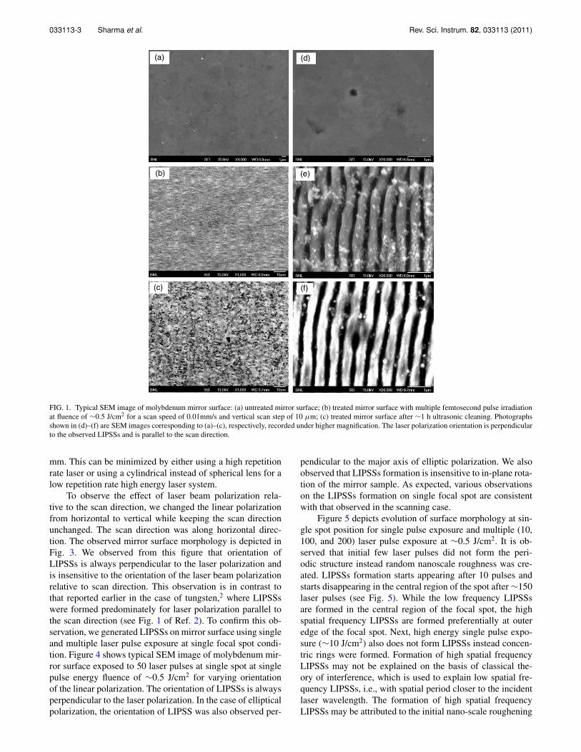
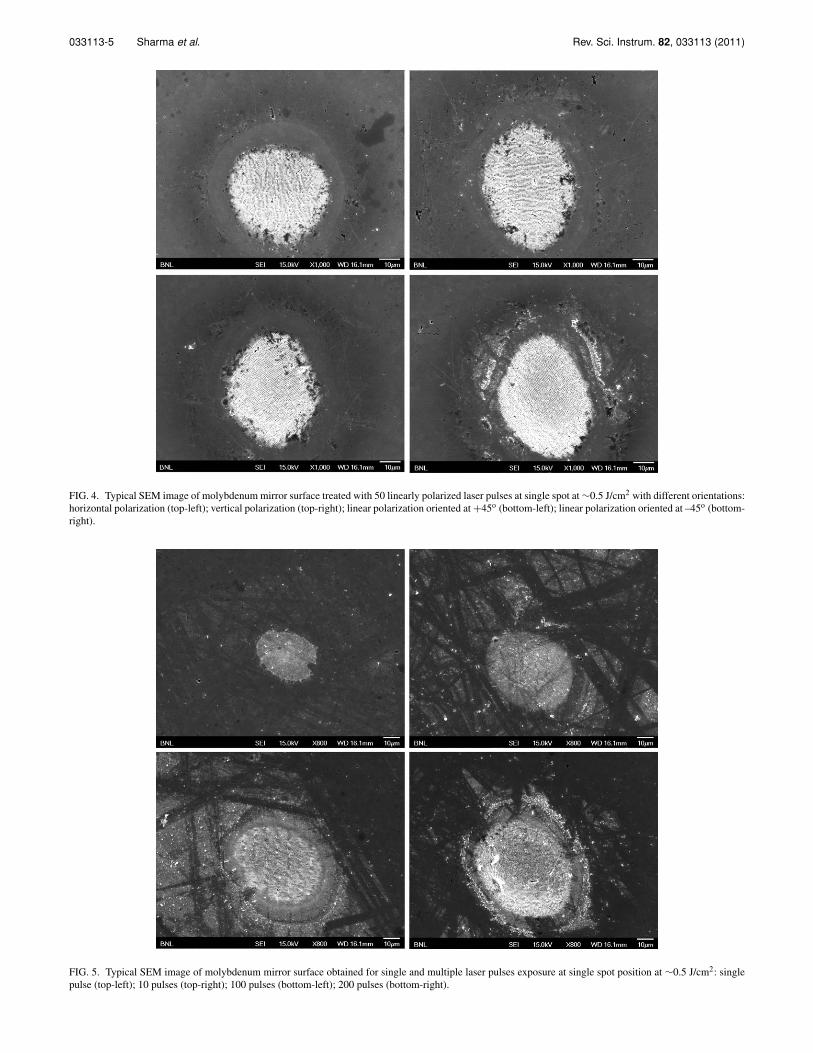
To observe the effect of laser beam polarization rela-tive to the scan direction, we changed the linear polarizationfrom horizontal to vertical while keeping the scan directionunchanged. The scan direction was along horizontal direc-tion. The observed mirror surface morphology is depicted inFig. 3. We observed from this figure that orientation ofLIPSSs is always perpendicular to the laser polarization andis insensitive to the orientation of the laser beam polarizationrelative to scan direction. This observation is in contrast tothat reported earlier in the case of tungsten,2 where LIPSSswere formed predominately for laser polarization parallel tothe scan direction (see Fig. 1 of Ref. 2). To confirm this ob-servation, we generated LIPSSs on mirror surface using singleand multiple laser pulse exposure at single focal spot condi-tion. Figure 4 shows typical SEM image of molybdenum mir-ror surface exposed to 50 laser pulses at single spot at singlepulse energy fluence of ∼0.5 J/cm2 for varying orientationof the linear polarization. The orientation of LIPSSs is alwaysperpendicular to the laser polarization. In the case of ellipticalpolarization, the orientation of LIPSS was also observed per-
pendicular to the major axis of elliptic polarization. We alsoobserved that LIPSSs formation is insensitive to in-plane rota-tion of the mirror sample. As expected, various observationson the LIPSSs formation on single focal spot are consistentwith that observed in the scanning case.
Figure 5 depicts evolution of surface morphology at sin-gle spot position for single pulse exposure and multiple (10,100, and 200) laser pulse exposure at ∼0.5 J/cm2. It is ob-served that initial few laser pulses did not form the peri-odic structure instead random nanoscale roughness was cre-ated. LIPSSs formation starts appearing after 10 pulses andstarts disappearing in the central region of the spot after ∼150laser pulses (see Fig. 5). While the low frequency LIPSSsare formed in the central region of the focal spot, the highspatial frequency LIPSSs are formed preferentially at outeredge of the focal spot. Next, high energy single pulse expo-sure (∼10 J/cm2) also does not form LIPSSs instead concen-tric rings were formed. Formation of high spatial frequencyLIPSSs may not be explained on the basis of classical the-ory of interference, which is used to explain low spatial fre-quency LIPSSs, i.e., with spatial period closer to the incidentlaser wavelength. The formation of high spatial frequencyLIPSSs may be attributed to the initial nano-scale roughening
033113-4 Sharma et al. Rev. Sci. Instrum. 82, 033113 (2011)
FIG. 2. Typical SEM image of treated mirror surface at pulse fluence of ∼0.5 J/cm2 and scan speed of 0.01 mm/s with different vertical scan step of: 10 μm(top-left); 20 μm (top-right); 30 μm (bottom-left); and 50 μm (bottom-right). The bottom-right image is under smaller magnification to depict a raster scan.
FIG. 3. Typical SEM image of treated molybdenum mirror surface at single pulse energy fluence of ∼0.5 J/cm2 during horizontal scanning at scan speed of 0.01mm/s with different orientation of linear polarizations: horizontal polarization (top-left); vertical polarization (top-right); linear polarization oriented at +45o
(bottom-left); and linear polarization oriented at –45o (bottom-right). This illustrates that formation of LIPSSs is always perpendicular to the linear polarizationand efficiency of LIPSS formation is independent of scan direction relative to the scan direction.
033113-5 Sharma et al. Rev. Sci. Instrum. 82, 033113 (2011)
FIG. 4. Typical SEM image of molybdenum mirror surface treated with 50 linearly polarized laser pulses at single spot at ∼0.5 J/cm2 with different orientations:horizontal polarization (top-left); vertical polarization (top-right); linear polarization oriented at +45o (bottom-left); linear polarization oriented at –45o (bottom-right).
FIG. 5. Typical SEM image of molybdenum mirror surface obtained for single and multiple laser pulses exposure at single spot position at ∼0.5 J/cm2: singlepulse (top-left); 10 pulses (top-right); 100 pulses (bottom-left); 200 pulses (bottom-right).
033113-6 Sharma et al. Rev. Sci. Instrum. 82, 033113 (2011)
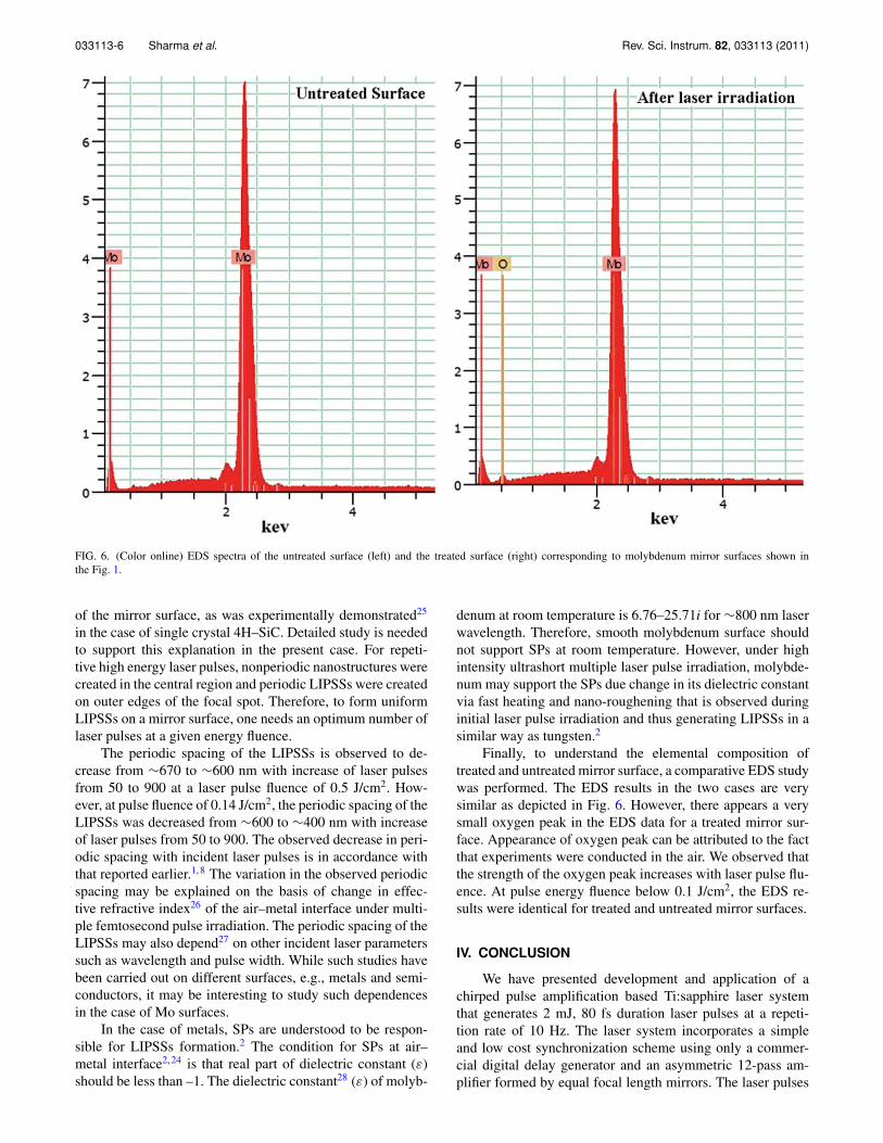
FIG. 6. (Color online) EDS spectra of the untreated surface (left) and the treated surface (right) corresponding to molybdenum mirror surfaces shown inthe Fig. 1.
of the mirror surface, as was experimentally demonstrated25
in the case of single crystal 4H–SiC. Detailed study is neededto support this explanation in the present case. For repeti-tive high energy laser pulses, nonperiodic nanostructures werecreated in the central region and periodic LIPSSs were createdon outer edges of the focal spot. Therefore, to form uniformLIPSSs on a mirror surface, one needs an optimum number oflaser pulses at a given energy fluence.
The periodic spacing of the LIPSSs is observed to de-crease from ∼670 to ∼600 nm with increase of laser pulsesfrom 50 to 900 at a laser pulse fluence of 0.5 J/cm2. How-ever, at pulse fluence of 0.14 J/cm2, the periodic spacing of theLIPSSs was decreased from ∼600 to ∼400 nm with increaseof laser pulses from 50 to 900. The observed decrease in peri-odic spacing with incident laser pulses is in accordance withthat reported earlier.1, 8 The variation in the observed periodicspacing may be explained on the basis of change in effec-tive refractive index26 of the air–metal interface under multi-ple femtosecond pulse irradiation. The periodic spacing of theLIPSSs may also depend27 on other incident laser parameterssuch as wavelength and pulse width. While such studies havebeen carried out on different surfaces, e.g., metals and semi-conductors, it may be interesting to study such dependencesin the case of Mo surfaces.
In the case of metals, SPs are understood to be respon-sible for LIPSSs formation.2 The condition for SPs at air–metal interface2, 24 is that real part of dielectric constant (ε)should be less than –1. The dielectric constant28 (ε) of molyb-
denum at room temperature is 6.76–25.71i for ∼800 nm laserwavelength. Therefore, smooth molybdenum surface shouldnot support SPs at room temperature. However, under highintensity ultrashort multiple laser pulse irradiation, molybde-num may support the SPs due change in its dielectric constantvia fast heating and nano-roughening that is observed duringinitial laser pulse irradiation and thus generating LIPSSs in asimilar way as tungsten.2
Finally, to understand the elemental composition oftreated and untreated mirror surface, a comparative EDS studywas performed. The EDS results in the two cases are verysimilar as depicted in Fig. 6. However, there appears a verysmall oxygen peak in the EDS data for a treated mirror sur-face. Appearance of oxygen peak can be attributed to the factthat experiments were conducted in the air. We observed thatthe strength of the oxygen peak increases with laser pulse flu-ence. At pulse energy fluence below 0.1 J/cm2, the EDS re-sults were identical for treated and untreated mirror surfaces.
IV. CONCLUSION
We have presented development and application of achirped pulse amplification based Ti:sapphire laser systemthat generates 2 mJ, 80 fs duration laser pulses at a repeti-tion rate of 10 Hz. The laser system incorporates a simpleand low cost synchronization scheme using only a commer-cial digital delay generator and an asymmetric 12-pass am-plifier formed by equal focal length mirrors. The laser pulses
033113-7 Sharma et al. Rev. Sci. Instrum. 82, 033113 (2011)
have been used to study LIPSSs on molybdenum mirror sur-faces. Uniform subwavelength grating on molybdenum mirrorsurfaces were formed for optimum laser pulse fluence,number of pulses, polarization, scan speed, and scan step. El-emental composition analysis was carried out using energydispersive x-ray spectroscopy.
ACKNOWLEDGMENTS
The authors gratefully acknowledge the technical supportof J. Walsh and W. Smith. A.K.S. also acknowledges Dr. P.D. Gupta and Dr. P. A. Naik from RRCAT, Indore for fruit-ful discussion and encouragement. This work was supportedby United States Department of Energy under Contract No.DE-AC02–98CH10886.
1A. Y. Vorobyev and C. Guo, J. Appl. Phys. 104, 053516 (2008); Appl. Phys.Lett. 94, 224102 (2009).
2A. Y. Vorobyev and C. Guo, J. Appl. Phys. 104, 063523 (2008).3A. Y. Vorobyev and C. Guo, J. Appl. Phys. 103(4), 043513 (2008).4A. V. Vorobyev, V. S. Makin, and C. L. Guo, J. Appl. Phys. 101, 034903(2007).
5A. Y. Vorobyev and C. Guo, Appl. Phys. Lett. 92, 041914 (2008).6A. Weck, T. H. R. Crawford, D. S. Wilkinson, H. K. Haugen, and J. S.Preston, Appl. Phys. A 89, 1001 (2007).
7Y. Yang, J. Yang, C. Liang, H. Wang, X. Zhu, D. Kuang, and Y. Yang, Appl.Phys. A 92, 635 (2008).
8L. Qi, K. Nishii, and Y. Namba, Opt. Lett. 34(12), 1846 (2009).9R. Myers, R. Farrell, A. M. Karger, J. E. Carey, and E. Mazur, Appl. Opt.45(35), 8825 (2006).
10Z. Huang, J. E. Carey, M. Liu, X. Guo, E. Mazur, and J. C. Campbell, Appl.Phys. Lett. 89, 033506 (2006).
11Y. Shimotsuma, P. G. Kazansky, J. Qiu, and K. Hirao, Phys. Rev. Lett. 91,247405 (2003).
12A. Y. Vorobyev, V. S. Makin, and C. Guo, Phys. Rev. Lett. 102, 234301(2009).
13K. Lin, Y. Lu, J. Chen, R. Zheng, P. Wang, and H. Ming, Opt. Express16(23), 18599 (2008).
14L. Zhou and W. Liu, Opt. Lett. 30(12), 1434 (2005).15D. Strickland and G. Mourou, Opt. Commun. 56, 219 (1985); J. V. Rudd,
G. Korn, S. Kane, J. Squier, and G. Mourou, Opt. Lett. 18(23), 2044(1993).
16A. K. Sharma, R. K. Patidar, M. Raghuramaiah, P. A. Naik, and P. D. Gupta,Opt. Express 14, 13131 (2006).
17S. Backus, C. G. Durfee, III., M. M. Murnane, and Henry C. Kapteyn, Rev.Sci. Instrum. 69(3), 1207 (1998).
18P. Georges, F. Estable, F. Salin, J. Philippe, P. P. Grangier, and A. Brun,Opt. Lett. 16(3), 144 (1991); C. Le Blanc, G. Grillon, J. P. Chambaret, A.Migus, and A. Antonetti, Opt. Lett. 18(2), 140 (1993).
19A. Antonetti, F. Blasco, J. P. Chambaret, G. Cheriaux, G. Darpentigny, C.Le Blanc, P. Rousseau, S. Ranc, G. Rey, and F. Salin, Appl. Phys. B 65,197 (1997).
20Y. W. Lee, Y. H. Cha, J. H. Yi, S. M. Nam, K. Lee, Y. J. Rhee, Y. U. Jeong,and H. K. Cha, Appl. Opt. 47(7), 1015 (2008).
21J. Wojtkiewicz and C. G. Durfee, Opt. Exp. 12(7), 1383 (2004).22K. Hong, S. Kostritsa, T. J. Yu, J. H. Sung, I. W. Choi, Y. Noh, D. Ko, and
J. Lee, Opt. Express 14(2), 970 (2006); A. K. Sharma, M. Raghuramaiah,K. K. Mishra, P. A. Naik, S. R. Kumbhare, and P. D. Gupta, Opt. Commun.252(4), 369 (2005).
23J. E. Sipe, J. F. Young, J. S. Preston, and H. M. van Driel, Phys. Rev. B 27,1141 (1983).
24W. L. Barnes, A. Dereux, and T. W. Ebbesen, Nature (London) 424, 824(2003).
25M. Sakakura and M. Terazima, Opt. Lett. 29, 13 (2004).26T. Tomita, K. Kinoshita, S. Matsuo, and S. Hashimoto, Appl. Phys. Lett.
90, 153115 (2007).27N. N. Nedialkov, S. E. Imamova, and P. A. Atanasov, J. Phys. D: Appl.
Phys. 37, 638 (2004); M. Huang, F. Zhao, Y. Cheng, N. Xu, and Z. Xu,ACS Nano 3(12), 4062 (2009).
28D. W. Lynch and W. R. Hunter, in Handbook of Optical Constantsof Solids, edited by E. D. Palik (Academic, San Diego, 1998), Vol. I,pp. 285, 312.