Temporal Logics as a formal language for specification of systems
Upload
independentCategory
view
2download
0
International Journal of Software Engineering and Knowledge Engineering © World Scientific Publishing Company
1
FORMAL SPECIFICATION AND ANALYSIS OF AN AGENT-BASED MEDICAL IMAGE PROCESSING SYSTEM
JUNHUA DING
Department of Computer Science East Carolina University
Greenville, NC 27858 [email protected]
XUDONG HE
School of Computing and Information Sciences Florida International University
Miami, FL 33199 [email protected]
Received (Day Month Year) Revised (Day Month Year)
Accepted (Day Month Year)
A mobile agent system is a special distributed system with moving programs in networks. Mobile agent systems provide a powerful and flexible paradigm for building high performance distributed systems. Due to dynamic configuration property, assuring quality of a mobile agent system is a challenge work. Formal specification and analysis of a mobile agent system provides one of the best approaches to ensure the correctness of a system design. However, it is difficult to find a formal specification tool for modeling a mobile agent system with an easy understand and concise model. In addition, it is a challenge but also important work to provide an automatic formal analysis approach for verifying whether a system specification correctly meets certain requirements in a mobile agent system. In this paper, a framework for specification and analysis of mobile agent systems is defined. First, Predicate/Transition nets are extended with dynamic channels for modeling mobile agent systems. The formalism has the expressive power to naturally model the software architecture of a mobile agent system, and easily capture the properties especially the mobility, mobile communication and dynamic configuration of a mobile agent system. Then, model checking is instrumented to the framework for automatically verifying the correctness of the specification of a mobile agent system specification. In order to illustrate the capabilities of the formalism and the verification strategy, a medical image processing system using mobile agents is modeled using the extended Predicate/Transition nets and system properties are verified using the SPIN model checker.
Keywords: formal specification; model checking; predicate/transition nets; mobile agents.
1. Introduction
Formally modeling and analyzing software architecture has profound impact on the development of high quality software systems. A rigorous approach toward architectural level system design can help to detect and eliminate design errors as early as possible in the development life cycle, to avoid costly fixes at the implementation stage, and thus to reduce overall development cost and to improve the quality of the systems. Software architecture is the overall structure and organization of a software system. With the

2 J. Ding, X. He
increase in the size and complexity of software systems, the design problem goes beyond using better algorithms and data structures. Designing and specifying the overall system structure and organization become more important [10]. In order to define software architecture, an architecture description language (ADL) is required to define system architectural models, and an analysis technique is needed to verify system properties. There are many ADLs, but research on software architecture development and analysis techniques is still not enough [15][34]. This paper provides the formalism for modeling mobile computing systems especially mobile agent systems, and proposes a systematic analysis approach for analyzing software architecture of mobile agent systems.
Petri nets [23] are a well-studied formal method with graphical and mathematical notations, noted for its many advantages on the behavioral specification and analysis of distributed concurrent systems, and they are also a promising tool for studying mobile computing systems that are characterized as being concurrent, asynchronous, distributed, parallel, and non-deterministic [40]. Petri nets can serve as a powerful medium of communication between practitioners and theoreticians: practitioners can learn from theoreticians on how to make their models more methodical, and theoreticians can learn from practitioners on how to make their models more realistic [28]. Predicate/Transition (PrT) nets are a class of high-level Petri nets that are especially suitable for modeling mobile computing systems due to their similarity to a logic mobile computing system, and the efficient reachability analysis [11][12][17][39], so that it enables us to focus on important and interesting system properties.
A mobile agent is an executing program representing its users and is capable to migrate from one node to another in a network, and, thus, is able to execute at different locations during its life span [8][14]. Mobile agent systems are useful to conserve bandwidth, reduce total completion time and latency, support dynamic load balancing, support offline operation in mobile computing environments, and support dynamic deployment [9][39]. Mobile agent systems have potential applications in fields like on-demand software systems, interactive training systems, and data mining systems. The most prominent characteristic of a mobile agent system is its ability to migrate agents (codes or data) from one computer to others in a network. It is difficult and complicate to formally specify and analyze a mobile agent system because agent migration leads to dynamic configuration of the software architecture of a mobile agent system. It is a major challenge to naturally model and analyze the dynamic communication and reconfiguration properties using PrT nets. The goal of this paper is to propose a framework that includes the formalism for naturally modeling mobile agent systems with concise and compact models, and a systematic analysis approach for formally analyzing the models of mobile agent systems. In order to achieve the goal, we extend PrT nets with dynamic channels, which was introduced from π-calculus [24][25] to dynamically build the communication between an agent and its environment. Tokens in PrT nets are passive, while agents in a mobile agent system are active. In order to bridge the gap between tokens and agents, a two-layer net style called “Net within Nets” is integrated with channels to the PrT nets for modeling mobile agent systems. “Net within Nets” was

Formal Specification and Analysis of an Agent System 3
first introduced in EOS (Elementary Object System) [35], where some nets (object nets) are wrapped as tokens in other nets (system nets)
One of the most important goals of building a formal model of a mobile agent system is to help ensure the correct design meets certain specifications and system properties such as liveness, deadlock-free, and concurrency [41]. Formal verification approach might be the straightforward chose for analyzing formal models [39][15]. However, most formal verification methods including formal prover are too hard and impractical for analyzing a real world software system such as a mobile computing system [5]. Few works provided a systematic analysis approach for analyzing a mobile agent system due to the complexity of the system. Modeling checking as an automatic verification method is already successfully used for analyzing enterprise software systems [6][13][31][41]. In this paper, the SPIN [16] model checker is chosen to analyze the software architectural model, and a hierarchical model checking technique is introduced to overcome the potential state explosion issue in model checking. We classify three levels of analysis: the system level analysis, the component level analysis, and the interaction level analysis. The system level analysis is used to verify system properties in the high-level models. The component-level analysis is used to analyze individual component properties. The interaction-level analysis is used to check properties that involve models in different levels, such as the interaction between an agent and its support system. Because each component is partial of the whole system model, we need transform each component model into an independent model and reduce its environments as interfaces using assume-guarantee technique [7][19][29][30].
In order to illustrate the specification and verification procedures of the extended PrT nets, we perform a case study of a mobile agent-based medical image system in this paper. Medical images, such as X-ray images, ultrasound images, or confocal images, are precious resources for clinical diagnosis, new drug discovery or pharmacy development [37]. Processing medical images is a challenge and tedious work because of huge data volume, heterogeneous formats and distributed locations of those images. Traditional approaches for processing medical images are high cost and inefficiency. Therefore, we design a medical image processing system using mobile agents. Services are designed as mobile agents that move among image servers and perform the image processing in servers to take advantage of locality of data resources and availability of running environments. Each client has an agent support system, which is used for creating and delivering agents to servers. Each server is installed with an agent support system, which is used to support and monitor the running of incoming agents. An agent might move to different servers with intermediate results following its itinerary so that to process images at different servers. The final results are delivered back to the client when an agent finishes its tasks. An agent-based medical image processing system is more flexible, higher efficient, more reliable and lower cost comparing to traditional methods.
In the following sections, the related works on specification and analysis of mobile agent systems are introduced in Section 2 before describing the extension of PrT nets with channels and the semantics of the new nets in Section 3. Section 4 describes how to

4 J. Ding, X. He
modeling a mobile-agent based medical image processing system using the extended PrT nets, and how to systematically analyzing the extended PrT net models of the system using the SPIN model checker. Finally, we outline our conclusions as well as future works in Section 5.
2. Related Works
PrT nets are the formalism to be extended with dynamic channels for modeling mobile agent systems in this paper. There are several different definitions for PrT nets such as the definition in [12] and [39], but the PrT nets in [39] is a subset of the PrT nets in [12]. In the definition [39], the predicate types are restricted to enumerable types, which are important for model checking because model checking only can be applied to finite state systems. The PrT nets defined in [39] are chosen as the basis of the formalism proposed in this paper.
2.1. Predicated/Transition Nets
Definition 2.1.1 (PrT Nets). A PrT net is a tuple (P, T, F, Σ, L, ϕ, M0), where: 1. P is a finite set of predicates (first order places), T is a finite set of transitions (P ∩
T = ∅, P∪T ≠ ∅), and F ⊆ (P×T) ∪ (T×P) is a flow relation, or simply a set of arcs. (P, T, F) forms a directed net.
2. Σ is a structure consisting of some sorts of individuals (constants) together with some operations and relations.
3. L is a labeling function on arcs. Given an arc f∈F, the labeling of f, L(f), is a set of labels, which are tuples of individuals and variables. The tuples in L(f) have the same length, representing the arity of the predicate connected to the arc. The zero tuple indicating a no-argument predicate (an ordinary place in Petri nets) is denoted by the special symbol <¢>.
4. ϕ is a mapping from a set of inscription formulae to transitions. The inscription on transition t∈T, ϕ(t), is a logical formula built from variables and the individuals, operations, and relations in structure Σ; variables occurring free in a formula have to occur at an adjacent input arc of the transition.
5. M0 is the initial or current marking.
( )1)(
00 UPp
pMM∈
=
where M0(p) is the set of tokens residing in predicate p. Each token is a tuple of symbolic individuals or structured terms constructed from individuals and operations in Σ.
Let { }FtpPpt ∈∈=• ),(: and { }FptPpt ∈∈=• ),(: be the pre-condition predicates and the post-condition predicates of transitions t, respectively. Let
{ }FptTtp ∈∈=• ),(: and { }FtpTtp ∈∈=• ),(: be the sets of input transitions and output transitions of predicate p, respectively. For a subset of predicates
U QppQPQ
∈•• =⊆ , and U Qp
pQ∈
•• = . Basically, a transition t in a PrT net is
enabled under marking M0 if there is a substitution θ such that l/θ ∈ M0(p) for any label l

Formal Specification and Analysis of an Agent System 5
∈ L(p, t) for all tp •∈ and ϕ(t) evaluates true with regard to θ, where l/θ yields a token by substituting all variables in label l with the corresponding bounded values with regard to θ. The firing of an enabled transition t removes all tokens in {l/θ: l ∈ L(t, p)} from each input predicate tp •∈ , and adds all tokens in {l/θ: l ∈ L(t, p)} to each output predicate
tp •∈ . After the firing of t, we get a new marking M’. Formally, M1(p) = M0(p) – {l/θ: l
∈ L(t, p)} for any tp •∈ , and M1(p) = M0(p) ∪ {l/θ: l ∈ L(t, p)} for any tp •∈ . We denote a firing/occurrence sequence as: nnn MtMtMtM >>> θθθ ...[[[ 2221110 , or,
simply, t1θ1t2θ2…tnθn, where t1(1 ≤ i ≤ n) is a transition, θi(1 ≤ i ≤ n) is the substitution for firing ti, and Mi (1 ≤ i ≤ n) is the marking after ti fires, respectively.
2.2. Modeling and Analysis of a Mobile Agent System
Mobility is the most important property in a mobile agent system [26][27], and there are several close related works on modeling the mobility of mobile agent systems. The logic agent mobility was modeled using two-layer PrT nets in [38][39], where the two-layer PrT nets introduced connectors to facilitate the communication between nets. The two-layer PrT nets keep the basic semantics of PrT nets in each net, so that their models are clear and they do not add more complexity for analysis due to the same analysis rule as ordinary PrT nets. Because the connectors in the two-layer PrT nets are statically defined, they cannot properly solve issues of dynamic configuration and communication between nets at different layers. In order to analyze or simulate the two-layer PrT net model of a mobile agent system, it is necessary to composing the agent model and the system models together. However, composing several nets using connector in the two-layer PrT is not intuitive and the presentation of the whole model in graph is difficult. In addition, the work in [39] did not provide a systematic approach for analyzing the model of a mobile agent system although some important properties were manually proved.
Different types of mobility of a mobile agent system were modeled in [18] using reference nets [20][21], which implemented certain aspects of “nets within nets”. Reference nets are multiple-layer colored Petri nets extended with channels and other operators, and they provide synchronous channels for transition communication and synchronization. Although reference nets are similar to our work, there are some important differences. First, reference nets were extended on colored Petri nets, but our work is on PrT nets. Second, each channel identifier in reference nets is a constant and qualified by incoming tokens, but channel names in our work could be variables, which are instantiated by an incoming token. The synchronous communication in reference nets is bi-direction, but the synchronous communication in our work is restricted to uni-direction. Input channel and output channel are defined in our work for specifying the communication direction to help analysis and understanding. Because some new operators were added to the colored Petri nets in reference nets, the semantics of reference nets are different from the basic semantics of colored Petri nets so that the complexity of formal analysis is increased in the reference nets. In addition, systematic

6 J. Ding, X. He
analysis of the models is absent in the work in [18] and [20], and automatically analyzing mobile agent systems was not discussed in either of [18], [20] or [21].
A type of Petri nets called G-nets were used for modeling multi-agent systems in [41], and model checking was used for analyzing the G-net models of multi-agent systems. However, the agents in [41] do not have the mobility property.
Channels were first introduced to colored Petri nets in [3], where the channel is same as the channel in reference nets except some differences in syntax. “Nets within nets” was first introduced in EOS. Our work implements the “nets within nets” style in PrT nets and extends EOS from three aspects. First, PrT nets instead of low-level place transition nets were chosen as the foundation of the formalism so that models of the extended PrT nets are more compact. Second, dynamic channels instead of texture labels on transitions were developed for facilitating the interaction and communication between object nets and system nets. The communication relationship between the communication parties are decided by channels at run time, so that the channel brings the dynamic property to the static structure of PrT nets. Third, EOS uses process markings to deal with the object fork-joint situation. Each object has to remember its state paths, and then the jointed state is calculated based on the least upper bound of the jointed object processes. In our method, each object only needs to keep its current state because objects are independent from each other and the marking of an object net represents its own state.
The π-calculus [24][25] is the first language offering features for specifying movement across channels. “The π-Calculus is a way of describing and analyzing systems consisting of agents which interacts among each other, and whose configuration or neighborhood is continually changing” [24]. π-Calculus does not support the location property, which is very important for mobile agent systems. π-Calculus focuses on the notation for processes, but it does not provide notations for environments of the computation. Comparing to π-Calculus, extended PrT nets with graphic notation are more intuitive for modeling mobile agent systems, and it is easier to simulate the execution of an extended PrT net model because it is executable. Mobile Petri nets [1] express process mobility by using variables and colored tokens in an otherwise static net, and dynamic Petri nets [1] extended mobile Petri nets with mechanisms for modifying the structure of Petri nets. However, dynamic Petri nets or mobile Petri nets bring forth the complexity of modeling and analysis because they cannot graphically model the movement of one subnet from the preset to the post-set of a transition when it fires. Mobile UNITY [32] is an extension of UNITY methodology [2], which is a state-based formalism with the foundation in temporal logic, to model dynamically reconfiguring distributed systems such as a mobile agent system. Each mobile process has a special location attribute, and the migration is reflected as changes of location values in mobile UNITY. PoliS [22] is a coordination language with hierarchical tuple-spaces and multi-set rewriting, which focuses on coordination problems in a multi-process system [4][22][33]. Nested spaces representing software components can move and change their positions in the tree. The communication is specified using the asynchronous mechanism through shared memory.

Formal Specification and Analysis of an Agent System 7
Polis is one of the early works exploring model checking for analyzing the model of a mobile computing system.
3. Extending PrT Nets with Channels
Considering the fact that a token in a PrT net may carry structured data and a PrT net is a structure, we allow a PrT net to be packed up as part of a token in another PrT net. Besides, additional constraints may be imposed on the enable of transitions in a PrT net. In order to model the interaction and communication between nets, dynamic channels are introduced to PrT nets. A channel is a mechanism associated with a transition for sending and receiving messages between transitions in different nets. Channels have two forms: an output channel for sending messages, and an input channel for receiving messages. A channel includes three parts: channel identifier, channel type, and parameters. A channel identifier could be a variable or a constant. If a channel identifier is a variable, it must occur at adjacent input arcs of the transition that contains the channel. An output channel is a channel identifier (constant or variable) followed by a ‘!’, which is followed by parameters. An input channel is a channel identifier (only constant) followed by a ‘?’, which is followed by parameters. The parameters define the type of information that can be passed through a given channel. Every channel is a synchronous channel, which has 0 buffer size so that an input channel has to fire with its matched output channel at the same time. Therefore, a channel is also a condition to the enable of its associated transition. When an output channel is enabled (i.e. its transition is enabled), its transition cannot fire until the matched input channel is enabled as well so that they fire at the same time. Tokens go through the channel from the input places of the output channel to the output places of the input channel following ordinary PrT net firing rules. Communication between two transitions in different nets only occurs when these two transitions have matched input and output channels. An input channel matches an output channel when both of them are enabled (without considering channel conditions) and the two channels have the identical channel identifiers, same number of formal parameters, and each corresponding parameter in the matched channels has compatible type. The following diagram illustrates the communication between two PrT nets using channels.
Figure 1 An illustration of communication using channels
In Figure 1, component A may communicate with component B, (some tokens will move from A to B via transition T and E). Transition T has an output channel c!<p1,p2>, and transition E has an input channel C?<p’1,p’2>. Parameters of each channel are treated as a data structure. Take channel expression c!(p1,p2) as an example, p1 and p2 compose the data structure (p1, p2), which defines the tokens passing through the channel. Under
T c!<p1,p2>
<c,p1,p2> E C?<p’1,p’2>
<p’1,p’2>
A B

8 J. Ding, X. He
certain marking M, transition T and E are enabled, and the value of channel variable c in transition T under the marking M is instantiated as C. In addition, the type of p1 is compatible to the type of p’1, and the type of p2 is compatible to the type of p’2.When transition T and E fire at the same time, tokens in A will move to B following PrT net firing rules.
Based on preceding discussion, we define the PrT nets with channels (called CPrT nets) in the following sections. For convenience, we introduce the operator \ for removing items from an expression. For example, ϕ(t)\c means removing expression c from expression ϕ(t). We define ∂(x) as the value of x, dom(x) as the value range of x, and ¢ represents empty.
3.1. Definition of a Channel
Definition 3.1.1 (Channel). A channel C is an interaction relation between transitions in a PrT net model, C = (t, e, ρ) where:
1. t is a transition in a PrT net N = (P, T, F, Σ, L, ϕ, M0), and ϕ(t) contains an output channel mc!(d1, … , dn), where mc is the channel variable, ! represents that mc is an output channel, and d1, … , dn are formal parameters for mc.
2. e is a transition in a PrT net N’ = (P’, E, F’, Σ’, L’, ϕ’, M’0), and ϕ(e) contains an input channel MC’?(d’1, … , d’n), where MC’ is the channel identifier (constant), ? represents that MC is an input channel, and d’1, … , d’n are formal parameters for MC’.
3. t communicates e via channel mc under making (M, M’), when 1) t and e both are enabled if channels are not considered, and 2) ∂ (mc) = MC’, 3) dom(di) ⊆ dom(d’i), 1 ≤ i ≤ n, where M is the marking of N, and M’ is the marking of N’. t and e fire at the same time following ordinary PrT net rules.
4. ρ ⊆ t × e is the interaction relation. The transition t sends data of (d1, … , dn) from t• to channel mc when t and e fire, and the transition e receives data of (d’1, … , d’n) from
channel mc and moves data from channel mc to •e when t and e fire.
Based on the definition of a channel, now we define a CPrT net: Definition 3.1.2 (CPrT net). A CPrT net is a tuple (P, T, F, Σ, L, ϕ, M0 , C, W), where:
1. (P, T, F, Σ, L, ϕ, M0 ) is a PrT net. 2. C is a finite set of input or output channels, ∀c ∈ C, c = (CI, CT, CP), where:
2.1 CI is the channel identifier, and CI ∈ Σ 2.2 CT is the channel type, and CT ∈ {!, ?}, where ! represents an output channel, and ? represents an input channel. 2.3 CP is the channel parameter representing the data type passing through the channel, and CP ∈ Σ.
3. W is a finite set of transitions, and W ⊆ T, ∀t ∈ W, ∃c ∈ C, ϕ(t)\c ≠ ϕ(t).
From the above definitions of channels and CPrT nets, we know that a CPrT net model might be consisted of several nets communicating through channels. An output channel identifier could be a variable, which is instantiated with a concrete value and match to an input channel at run time so that the communication topology is dynamically built based on the context of the communication transitions.

Formal Specification and Analysis of an Agent System 9
3.2. Behaviors of CPrT Nets
Before we can simulate and analyze a CPrT net model, we need define the semantics of CPrT nets. We interpret a CPrT net using ordinary PrT net rules through transforming a CPrT net into a PrT net, and then prove these two models are behaviorally equivalent, which means there is a one to one correspondence between markings and enabled steps of these two nets [3]. Although we interpret CPrT nets using PrT nets, we never really transform CPrT nets into PrT nets when we model a system. We model a system directly using CPrT nets without constructing the equivalent PrT nets.
In CPrT nets, some transitions are associated with input or output channels, which affect the firing rules of these transitions because these channels constrain the enabling of these transitions. But transitions with channels can be transformed into regular transitions through adding predicates and input/output functions. After we transform all transitions of a CPrT net into regular transitions, this special PrT net is transformed into an ordinary PrT net. We can use ordinary PrT net rules to interpret, analyze and simulate the transformed models.
In the following section, we discuss behaviors of three different transitions: a transition that has not any channel, a transition that has an output channel, a transition that has an input channel. In addition, we discuss synchronous communication between transitions that have matched channels.
3.2.1. An ordinary transition
Transition t has not any channel expression within its inscription ϕ(t). Transition t is enabled and fires following enabling and firing rules of ordinary PrT nets.
3.2.2. A transition with an output channel
Transition t has an output channel c within its inscription ϕ(t). We denote c.CI as the channel identifier, c.CT as the channel type, and c.CP as the channel parameters. Transition t is enabled under marking M0 if there is a substitution θ such that l/θ ∈ M0(p) for any label l ∈ L(p, t) for all tp •∈ and ϕ(t)\c (without considering the output channel c) evaluates to true regarding θ, where l/θ yields a token by substituting all variables in label l with the corresponding bounded value θ, and substituting c.CI and c.CP with the value θ (c.CI/θ, c.CP/θ). The firing of the enabled transition t removes all tokens in {l/θ: l ∈ L(p, t)} from each input predicate tp •∈ , and adds all tokens in {l/θ: l ∈ L(t, p)} to each output predicate p ( •∈ tp ). The firing process of the output channel can be looked as a new virtual and temporary output place λ representing the output channel, λ = c.CI/θ for t, where •• ∪= tt λ , an arc γ from t to place λ, a label ψ on γ where ψ is <c.CI/θ, c.CP/θ>, ψ∪= ),(),( ptLptL , •∈ tp , and token (c.CP/θ) into place λ.
When a transition that has an output channel fires, it instantiates the channel identifier variable and the channel parameters (based on the tokens in its pre-conditions and inscriptions on the arcs), wraps the instantiated parameters as structured data, and moves the data to the channel. The virtual place is labeled as the same value as the

10 J. Ding, X. He
instantiated identifier of the channel when the channel is firing. The token structure of the virtual place consists of the channel parameters. The inscription on the arc from the output channel transition to the virtual place consists of the channel name and the parameter of the channel. Tokens in input places of the output channel transition are moved to output places of the transition (including the virtual output places) according to PrT nets firing rules. Figure 2 shows a snapshot view of an output channel during the firing as a PrT net.
Figure 2 A snapshot PrT net view of an output channel during firing In Figure 2, transition t has an output channel p!(msg), under certain marking M, the token in place s is <P, MSG>, then p = P, msg = MSG, and t is enabled (assume there is a matched input channel under the marking M). As soon as t fires, token <P, MSG> in place s will be moved to the virtual place P (and it is immediately moved to the output places of the matched input channel).
Channel identifier in a CPrT net might be variables and their values are instantiated at run time. However, place names in regular PrT nets are pre-defined, so that they cannot be changed at run time. Channel places are virtual places for understanding CPrT nets. When we look at a channel transition as a regular transition, the transition with an output channel is virtually connected to a set of places through auxiliary places and transitions from PrT nets point of view. Each place in the set has a unique name that is one of possible values of the channel identifier.
3.2.3. A transition with an input channel
Transition t’ has an input channel c’. Transition t’ is enabled under marking M0 if there is a substitution θ’ such that l/θ’ ∈ M0(p) for any label l ∈ L(p, t’) for all 'tp •∈ and ϕ(t’)\c’ (without considering the input channel c’, c’ is false at this time) evaluates to true regarding θ’, where l/θ’ yields a token by substituting all variables in label l with the corresponding bound value θ’, and substituting c’.CP with the value θ’, i.e. c’.CP/θ’, c’.CI is a constant. At the same time, a transition t has an output channel c, and t is enabled under marking M0 and there is a substitution θ, so that c’.CI = c.CI/θ, c’.CT = ?, c.CT = !, and c.CP/θ’ ⊆ c’.CP/θ (type of each parameter of c is compatible to the type of the corresponding parameter of c’). At this situation, transition t and e have to fire at the same time as an atomic transition. We can interpret the firing procedure of a transition that has an input channel using ordinary PrT nets. We know that there is one virtual place λ of the matched output channel, and λ = c.CI/θ is treated as a new virtual input place of t’, '' tt •• ∪= λ ; there is an arc γ from place λ to transition t’, and a label ψ on γ, where ψ is <c.CI/θ, c.CP/θ>, ψ∪= )',()',( tpLtpL , 'tp •∈ . The firing of the enabled transition t’ removes tokens in {l/θ’: l ∈ L(p, t’)} from each input place p ( 'tp •∈ ), and adds tokens in {l/θ’: l ∈ L(t’, p)} to each output place •∈ 'tp following ordinary PrT net firing rules.
ss t tp!(msg)(p, msg) (p, msg) (p, msg) P

Formal Specification and Analysis of an Agent System 11
We discuss the input channel and the output channel behaviors separately for the reason of simplicity. However, each channel only fires with its matched channel at the same time as an atomic transaction. When we interpret an input channel using ordinary PrT nets, each input channel is looked as a virtual input place of the transition that has the input channel, and the parameter for the channel as an inscription on the arc that directs from the input place to the transition. The place is labeled using the same name as the identifier of the input channel. The virtual input place for the input channel is fused with one matched virtual output place of the output channel at run time. As soon as the transitions that have matched channels fired, they will change to the status before firing. Figure 3 illustrates the transformation from an input channel to an ordinary PrT net. In the left side of Figure 3, transition t has an input channel C?(msg), the corresponding PrT net is represented in the right side, which has a virtual place C representing the identifier of the channel (and the virtual input place).
Figure 3 A PrT net view of an input channel
3.2.4. The synchronous communication between channels
The basic idea behind the transformation of a CPrT net into an equivalent PrT net is to merge transitions that involve in the channel communication. When the transition that has an output channel is merged with the transition that has the matched input channel during the communication (the two transitions are firing at the same time), the arcs of the merged transition are the union of the arcs of the two communication transitions. The guard condition of the merged transition is formed by the conjunction of the guards from the communication transitions and an expression that is used to decide the equivalence of channel names of the input channel and the output channel. Because the binding of each of the two communication transitions is independent, it is important to make sure the set of variables of the two communication transitions are disjoint before the transitions can be merged [3]. For each communication transition t, each variable v ∈ var(t) is renamed with a new variable s of the same type as v, and make sure that the name of each new variable is unique in the global domain. Figure 4 illustrates the transformation procedure.
Figure 4 The synchronous communication between channels The transition t and e have to be in different nets, and both of them are enabled under certain marking (M1, M2). The transition t has channel c!<p1, p2>, and the transition e has
t c!< p1, p2>
e C?< p’1, p’2>
te c = C
<c, p1, p2> <p’1, p’2>
<c, s1, s2> <s1, s2>
t t C?(msg)
(msg) (msg) C ( msg)

12 J. Ding, X. He
channel C?<p’1, p’2>. The value of output channel variable c equals to C under the marking (M1, M2). The numbers of parameters of the input channel and the output channel are equal, and type of each corresponding parameter in both channels is compatible, i.e. dom(p1) ⊆ dom(p’1), dom(p2) ⊆ dom(p’2). Transition t and e fire at the same time as an atomic transaction, so that token <p1, p2> is moved from the input places of t to the output places of e. The enabling and firing sequences of the CPrT net are the same as the transformed PrT net, and the results of the CPrT net firing is the same as the results of the transformed PrT net. When t and t’ fire, a new marking M’ is generated. Formally, M’1(p) =M’0(p) – {l/θ: l ∈ L(p, t)} – {l/θ’: l ∈ L(p, t)} for any tp •∈ or 'tp •∈ , and M’1(p) = M’0(p) ∪ {l/θ: l ∈ L(t, p)}∪{l/θ’: l ∈ L(t’, p)} for any p ( •∈ 'tp or •∈ tp ). If more than one output channel matches one input channel under certain marking in a CPrT net model, only one output channel can communicate with the input channel each time. The output channel chosen to communicate with the input channel is non-deterministic.
3.3. Two-Layer CPrT Nets
The “net within net” from EOS is introduced to PrT nets for building two layer PrT nets with channels. In the net within net style, a token in a net might be a PrT net as well. A PrT net wrapped as a token is called token net, and a PrT net that has any token net is called system net. Formal definitions of the two-layer CPrT nets, the communication between system nets and tokens nets will be defined in this section.
Definition 3.3.1 (Two-layer CPrT Nets). A two-layer CPrT net is a tuple STN = (SN, TN, ρ), where:
1. SN is a finite set of system nets, SN = {SN1, SN2, …, SNn}, and SNi (1 ≤ i ≤ n) is a CPrT net, SNi = (P, T, F, Σ, L, ϕ, M0 , C, W).
2. TN is a finite set of token nets, TN = {TN1, TN2, …, TNm}, and TNi (1 ≤ i ≤ m) is a CPrT net, TNi = (P’, T’, F’, Σ’, L’, ϕ’, M’0 , C’, W’).
( ) ( )2
1U
n
iii SNTN
=
Σ⋅∈
3. ρ ⊆ W × W’ is the occurrence relationship between channels.
3.3.1. The definition of occurrence rules in two-layer CPrT nets
There are three types of occurrence rules for two-layer CPrT nets: system autonomous, interaction, and object autonomous. The classification and concept of the occurrence rules come from [35], and the definition is similar to the definition 2.2 in [36], but we extended the definition with channels instead of the synchronization variables. For convenience of description, we assume there are only one system net and one token net in a CPrT net model. The marking of the system net is M, and the marking of the token net is M’, so that the marking of the CPrT net is (M, M’).
System autonomous occurrence means when a transition in a system net fires and may move a token net from its input place to its output places, but the token net does not change its state during the moving, i.e. there is not any transition firing in the token net

Formal Specification and Analysis of an Agent System 13
during the system net updates its state. If the fired transition is t, and M [t > M1, then the marking of the net changes: (M, M’)[t > (M1, M’).
Interaction occurrence means a transition of a system net and a transition of the token net in the system net fire at the same time under marking (M, M’). The fired transitions are transitions that have matched channels under marking (M, M’). The system updates its marking after transitions fire: (M, M’)[(t, t’) > (M1, M1’), where t is the fired transition in system net and the system net marking is changed from M to M1: M[t > M1, and t’ is the fired transition in the token net and the token net marking is changed from M’ to M’1: M’[t’ > M’1.
Object autonomous occurrence means a transition in the token net updates its state, but its system net does not fire any transition under the current marking (M, M’), i.e. the token net updates its state within a place of the system net without any interaction from the system net. The system updates its marking after transitions fire: (M, M’)[t’ > (M, M1’), where t’ is the fired transition in the token net and M’[t’ > M’1.
Definition 3.3.2 (Occurrence rules). There are three different occurrence rules: 1. System autonomous: There is a transition t ∈ SN⋅T, TN ∈ SN.P. Under a system
marking (M, M’), where M is the marking of SN, and M’ is the marking of TN, t is ready to fire. t fires by itself without any interaction from the token net, so that the change of the system marking is: (M, M’)[t > (M1, M’), where 1[ MtM > , when t fires.
2. Interaction: There is a transition t ∈ SN⋅T, and TN ∈ SN.P, M is the marking of SN, and M’ is the marking of TN; the system marking is (M, M’). Suppose t has an output channel such as c!(p1, p2), t’ ∈ TN⋅T’ is a transition with the input channel C? (p’1, p’2), and c.CI = C under marking (M, M’), and dom(p1) ⊆ dom (p’1) , dom(p2) ⊆ dom(p’2). t and t’ fire at the same time, 1[ MtM > , 1''[' MtM > . Then the system marking becomes (M1, M’1). If t’ ∈ TN⋅T’ has an output channel such as c!(p’1, p’2), t ∈ SN⋅T is a transition with the input channel C? (p1, p2), and c.CI = C under marking (M, M’), and dom(p’1) ⊆ dom (p1) , dom(p’2) ⊆ dom(p2). t and t’ fire at same time, then 1[ MtM > , 1''[' MtM > . The system marking becomes (M1, M’1).
3. Object autonomous: There is a transition t’ ∈ TN⋅T’, and t ∈ SN⋅T, TN ∈ t• , or TN ∈ •t , t’ fires, 1''[' MtM > , but SN does not fire any transition, the marking of SN still is M. The system marking becomes (M, M’1).
The interaction occurrence rules define the basic communication between a system net and a token net. The communication between two nets at the same layer (such as two system nets, or two token nets) follows the rules of the communication between two nets in CPrT nets.
3.3.2. Behavioral equivalence of CPrT nets and PrT nets
We already showed CPrT nets can be transformed into behaviorally equivalent PrT nets, which means although adding channels to PrT nets increases the possibility for creating compact and comprehensive models, its computational power is same as PrT nets. By behavioral equivalence, a CPrT net has the same behaviors as its transformed PrT nets. There is a one to one correspondence between the markings and the enabled steps of the models of PrT nets and the models of CPrT nets. Therefore, we can generalize the basic

14 J. Ding, X. He
concepts and the analysis methods of PrT nets to CPrT nets, and a CPrT net has a given property if and only if the equivalent PrT net has the corresponding property [3]. The following algorithm formally transforms a CPrT net into a PrT net.
Algorithm 3.3.1 (Transform a CPrT net into a PrT net). Given a CPrT net model ∏ = (SN, TN, ρ), where SN is a CPrT net, SN = (P, T, F, Σ, L, ϕ, M0, C, W), TN is a CPrT net, TN = (P’, T’, F’, Σ’, L’, ϕ’, M’0, C’, W’), ρ ⊆ W × W’. ∏ can be transformed into a PrT net N = (P’’, T’’, F’’, Σ’’, L’’, ϕ’’, M’’0) using the following steps:
1. Split each transition that has an output channel in ∏ into a group of transitions. If a transition t ∈ W (or W’), the inscription ϕ(t) of t includes an output channel c,
(ϕ(t)\c)&& c = ϕ(t), c ∈ C, suppose dom(c.CI) = {C1, C2, … , Cn}, c.CT= !, c.CP = <p1, p2>. Clone transition t into n transitions t1, t2, …, tn, where tti
•• = , •• = tti (1≤ i ≤ n), draw
directed arcs from it• to ti and ),,( tpLl ∈∀ p∈ t• , then l ∈ L(p, ti), draw directed arcs
from ti to •it and ),,( ptLl∈∀ p ∈ •t , then l ∈L(ti, p). The inscription of ti is (ϕ(t)\c)&&
(c = Ci), (1≤ i ≤ n). 2. If more than one output channel match the same input channel under the marking
M of ∏, then some simple auxiliary places and transitions are needed in the transformation.
Figure 5 A transformation of a situation multiple output channels match one input channel
In Figure 5, under the marking M, transition t1 transformed from an output channel that has a condition (c = C1) for matching the input channel C1, and another transition s1 that is transformed from another output channel has the same condition (c = C1) for matching the input channel C1. The following steps are used to transform transition t1 and s1, and the transformation keeps the nondeterministic of the match between t1 or s1 and the input channel C1.
2.1 A transition f is added, ϕ(f) = (c = C1), and a place g is added, }{gf =• , a directed arc from f to g is added to connect f and g, l(f, g) = <¢>.
2.2 One direct arc is added to connect g to t1, and l(g, t1) = <¢>, another direct arc is added to connect g to s1, and l(g, s1) = <¢>. ( ) ),,(),(,, 1111 sslttlfflstf •••••• ∪=∪= ϕ(f) =(c = C1).
2.3 ϕ(t1) =ϕ(t1)\(c = C1), ϕ(s1) =ϕ(s1)\(c = C1), and others for t1 and s1 are kept without change.
This transformation is easily extended to the case that more than two output channels match to the same input channel under certain marking. In CPrT net, the identifier of any input channel is unique in the whole model; therefore, it will not occur that two input channels match the same output channel under a certain marking.
3. Merge matched transitions.
c = C1 f g
<¢><¢>
<¢> s1
t1

Formal Specification and Analysis of an Agent System 15
If a transition e ∈ W’ (or W), the inscription of e includes an input channel R, (ϕ(e)\R)&& R = ϕ(e), R ∈ C’, R.CI = C1, R.CT= ?, R.CP = <p’1, p’2>. If there is a transition t1∈ W (or W’), and(ϕ(t1)\(c = C1))&& (c = C1) = ϕ(t1), and c.CP = <p1, p2>, dom(p1) ⊆ dom(p’1), dom(p2) ⊆ dom(p’2). Then t1 and e are merged together to form a new transition r. etr ••• ∪= 1 , ••• ∪= etr 1 , draw directed arcs from r• to r and
),(),( 1 epLtpLl ∪∈∀ p∈ et •• ∪1 , then l ∈ L(p, r), draw directed arcs from r to •r and
),(),( 1 peLptLl ∪∈∀ p ∈ •• ∪ et , then l ∈L(r, p).The inscription of r is (ϕ(t1)\c)&& (c = C1)&& (ϕ(e)\R).
4. Rename variables If a variable v1 ∈ L(p, t1) ∪ L(t1, p) ∪ ϕ(t1), v2 ∈ L(p, e) ∪ L(e, p) ∪ ϕ(e), v1 and v2
have the same meaning, then replace v2 as v1 on L(r) and ϕ(r). If a variable v ∈ L(p, t1) ∪ L(t1, p) ∪ ϕ(t1), and v∈ L(p, e) ∪ L(e, p) ∪ ϕ(e), but v has different meaning in t and e, then replace v coming from transition e as a different variable vt without confliction in L(r)\L(t1) and ϕ(r)\ϕ(t1).
5. Composing a PrT net based on above steps. Repeat above steps until all matched transitions are merged. Finally, the CPrT net is
transformed into a PrT net N = (P’’, T’’, F’’, Σ’’, L’’, ϕ’’, M’’0), which defines the transformed PrT nets.
3.4. An Example: Modeling a Client Server System Using CPrT Nets
In a client server system, all service programs are located in the server side. The CPrT net model of a client server system has one client net and one server net. The client and the server communicates through channels. The model for the server is a two-layer CPrT net, where the system net models the environment, and the token nets represent the programs of services. A token net is instantiated as one or more instances or object nets in the system net. In other word, object nets are packed as tokens in the system net. Each token net represents one service, which can serve different clients at the same time. Figure 6 shows the CPrT net model of a client server system:
In Figure 6, C in the client net is a channel for receiving messages from servers, and the only parameter r of channel C is for receiving result from a server. The transition t sends a request to the server for some services, and the request includes the server name s, the client name C, and service requisition m, which includes the service name ID and parameters p. In the system net, S is a channel for receiving messages from clients, where S has two parameters: sa for the source client, and m for the service requisition. The place p1 has a list of services the server can provide. The place p2 include all active object nets. The parameter a has the form {ID1(obj1, obj2, … , objn), ID2(obj1, obj2, … , objm), … , IDp(obj1, obj2, … , objk)}, where IDi is the type of the service, obji is the instance of the type of service. The service instances are staying in place ps during its life span. The transition e generates an instance (start the service) of a type of service, and then forwards the requisition data to the object. The unique service instance ID is assigned based on a in place p2, and e updates a when it generates an object. As soon as a result r is ready, it is delivered to the client, and the corresponding object becomes inactive and removed from place p2. In the service net, channel ID is a dummy channel name representing the service. The ID is instantiated as a real value when an object is

16 J. Ding, X. He
instantiated from this service and moved out from ps. The computation result of the service is sent back to the system as soon as the result is ready.
Figure 6 A CPrT net of a Client-Server system
4. A Medical Image Processing System
4.1. Background
In order to find useful diagnostic information, thousands of medical images may need to be processed. There are so many different types of medical images, or even same type of images might be taken using different instruments with different formats, which prevent the data interoperability. Different types of images maybe stored in different databases at different sites with different data management systems or security systems, so that images might be only accessed or processed under particular environment (software and hardware), which might not be available for some users. Users of image data could be research groups, hospitals, or pharmacy companies, while providers of those images could be analysis laboratories. The separation between users and the data providers is a natural client server structure – each image provider is a server that provides data and computing services (programs) for clients. It is reasonable that each server provides some common services, but no any server can provide all requested services to satisfy the requirements from so many different users. The traditional solution is users copy data from image providers and processes data in their local sites. Due to the heterogeneous running environments between the data providers and users, copying and processing data in local sites are very expensive. Furthermore, users are very difficult to get the latest data using the copying method. An alternative way is users provide required service programs to the servers so that these services can be installed and run in the server sides. The second method needs servers to manage lots of services and keep update services coming from different users. However, managing incoming services from different users is not possible for most of data providers. Due to security consideration, it is dangerous to allow remote users install and maintain services in servers by themselves, and it is also
C?( r) t
svr = m.id
s!(C, m) <s,C,m>
S?(sa, m)
<sa, m.id,m.p>
<svr>
<sa,id,p> a.id.o!(p)<sa,id,p> <a>
<sa,o><sa,o,r>
sa!(r)
<sa,o,r>
o?(s,r)<sa,o>
<a>
<sa, m >
<s,C,m>
ID?(p) ID!(S,r)<r><r><p> <p>
Client
Server
Service
System
p1
p2
e
<s, m>
ps
t

Formal Specification and Analysis of an Agent System 17
challenge to a user to understand the administration of different computing environments in server sides.
In order to overcome above problems, we design a medical image processing system using mobile agents. An agent might move to different servers with intermediate results based on its itinerary so that to process images at different servers. The final results are delivered back to the client when an agent finishes its tasks. The advantages of this computation model include: 1. Because agents move to server sides and they perform the processing of images locally, it is neither necessary to copy and maintain the raw data in the client, nor necessary to provide support environments for processing images in the client. 2. Because agents move to the server sides, agents can work offline in servers to save bandwidth comparing to traditional client server systems. 3. Users only need focus on the development of processing algorithms without considering any environment issue, which is taken cared by agents and the agent support systems. 4. Because agents are running at server sides, users can access the latest data in server sides quickly. 5. A server does not need to provide any application related service such as image processing programs so that the burden on the server sides is much reduced. 6. Because an agent can automatically move to multiple servers based on intermediate results and its itinerary, it minimizes the user involvement during the processing.
The system structure of a mobile agent system is similar to the traditional three-tier client server structure, but it has three important differences from the client-server paradigm. 1. The business logic in the server side is supplied by clients, and they are dynamically deployed and configured in the server side by mobile agents. 2. As soon as one agent arrives at its destination server, the connection between the client and the server is not necessary until someone requests re-connection. In client server systems, the connection is required during execution of the required task. 3. Mobile agents can migrate from one server to others during their life spans according to their pre-defined itineraries and intermediate results. However, the configuration between client and server are statically defined in traditional client server systems.
4.2. A Medical Image Processing System
In this section, we introduce an application of a medical image processing system using mobile agents. The system is used for processing confocal images of human blood cells taken by image-based flow cytometry, and histogram images of human blood cells taken by traditional flow cytometry. The system is used to find a disease pattern from confocal images, and then to evaluate the pattern based on the corresponding histogram data, whose pattern of this type of disease was already confirmed. We call the system as MIP (Medical Image Processing) system. MIP needs retrieve and process images from two different databases: one is confocal image database located in a research laboratory, and another is histogram image database located in a clinical laboratory.
Researchers process images using different algorithms and protocols, which are implemented as mobile agents. Each agent includes a program, some algorithms and protocols. An algorithm is rules or procedures for processing data, and a protocol is used for selecting and combining data based on different strategies. In other words, protocols are used for selecting data from images; algorithms are used for processing data, and programs are used for integrating and executing algorithms and protocols. Clients (researchers) send mobile agents with particular algorithms and protocols to servers. An agent runs locally in a server, and move to different servers to access and process data

18 J. Ding, X. He
from different databases based on its intermediate results, and finally deliver result back to its client. MIP has advantages such as offline computation, saving money on data transferring and maintenance, synchronization with latest data resources, flexibility on providing different services, and reducing data transferring in networks. Here we give a brief description of import components of the MIP system.
Client: Clients are used for creating and sending out agents for users. Agents: Each agent includes at least following parts: a program for accessing and
processing images in the servers; an itinerary of visiting path and a strategy for updating its itinerary based on runtime results; an authority from its users; a resource requirements specification; and a log file of important events.
Server: A server includes one part providing basic databases and file services and another part providing the agent execution support.
Database: Databases include database management systems and image data. Result: The results include intermediate and final results. An agent may process
intermediate results on one server and then bring the result to another sever to continue its work. Results are delivered back to the client when an agent finishes its task.
4.3. Specification of a MIP System
The MIP system includes two types of agent support systems: one is for clients to create and manage agents, and another is for servers to support the management and execution of incoming mobile agents. All agent structures are same except the algorithms and protocols are different. In the CPrT model of the MIP system, only one agent template is modeled, which can be instantiated as many different agents for different purposes. The static view of an MIP architecture is: MIP = {a, C, S1, S2}, where a is the agent template, C is the agent support system for the client, S1 and S2 are agent support system for the confocal image server and the histogram data server, respectively. Agents are created in C based on agent template a, and then they are sent to S1 or S2 by the client C. Agents do not cooperate each other, but one agent can move between server S1 and S2 with results, and finally comes back to C with results.
4.3.1. Specification of an agent
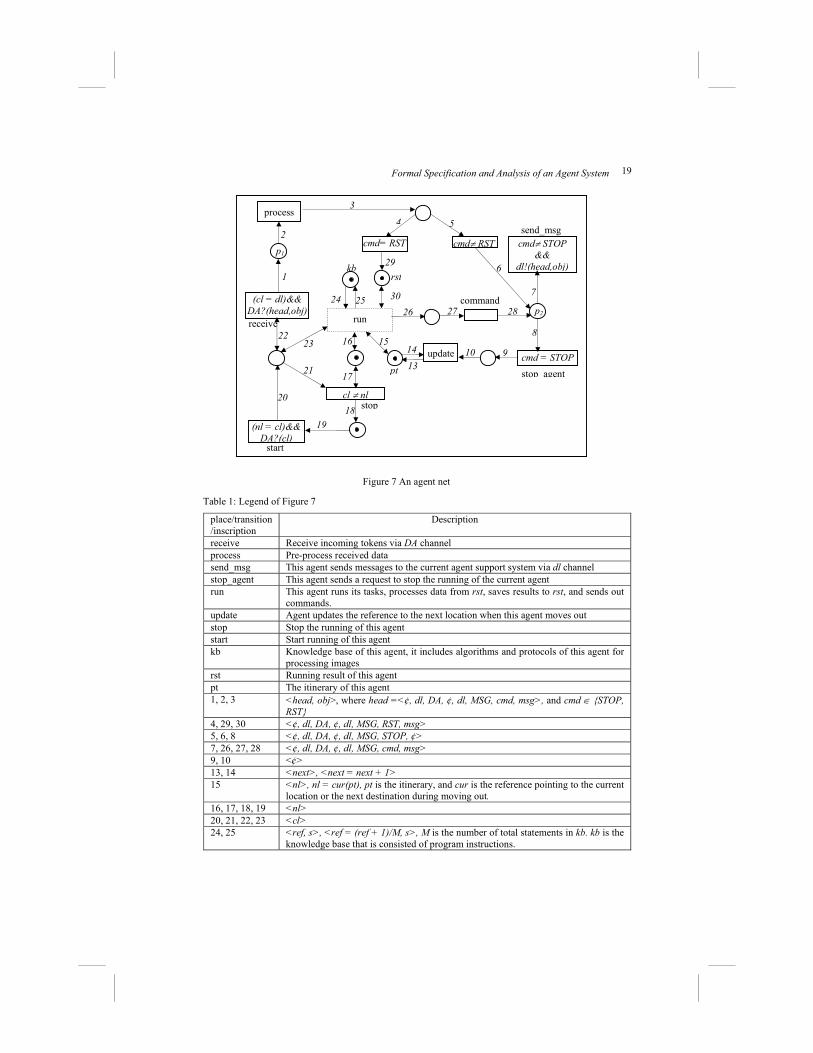
Each agent only communicates its host system or the agent support system directly. An agent sends retrieving statements (consisting with protocols) to the host, and then the agent support system in the host searches its databases, and sends back image data to the agent. As soon as the agent gets the data, it processes the data and saves the processed results. Each agent executes its task according to its statements in its knowledge base (algorithms and protocols) and its intermediate results. If an agent wants to visit another server, it requests the host to move it out, but the host also can kick the agent out at any time. Figure 7 shows the agent net of the MIP system.
Formal Specification and Analysis of an Agent System 19
Figure 7 An agent net
Table 1: Legend of Figure 7
place/transition /inscription
Description
receive Receive incoming tokens via DA channel process Pre-process received data send_msg This agent sends messages to the current agent support system via dl channel stop_agent This agent sends a request to stop the running of the current agent run This agent runs its tasks, processes data from rst, saves results to rst, and sends out
commands. update Agent updates the reference to the next location when this agent moves out stop Stop the running of this agent start Start running of this agent kb Knowledge base of this agent, it includes algorithms and protocols of this agent for
processing images rst Running result of this agent pt The itinerary of this agent 1, 2, 3 <head, obj>, where head =<¢, dl, DA, ¢, dl, MSG, cmd, msg>, and cmd ∈ {STOP,
RST} 4, 29, 30 <¢, dl, DA, ¢, dl, MSG, RST, msg> 5, 6, 8 <¢, dl, DA, ¢, dl, MSG, STOP, ¢> 7, 26, 27, 28 <¢, dl, DA, ¢, dl, MSG, cmd, msg> 9, 10 <¢> 13, 14 <next>, <next = next + 1> 15 <nl>, nl = cur(pt), pt is the itinerary, and cur is the reference pointing to the current
location or the next destination during moving out. 16, 17, 18, 19 <nl> 20, 21, 22, 23 <cl> 24, 25 <ref, s>, <ref = (ref + 1)/M, s>, M is the number of total statements in kb. kb is the
knowledge base that is consisted of program instructions.
process
cmd≠ STOP &&
dl!(head,obj)
cmd = STOP 16
receive
(nl = cl)&& DA?(cl)
kb
run
cl ≠ nl
start
1
2
4 5
6
7
1721
1819
20
2223
2624
pt
update
25
1514 91013
27 p2
(cl = dl)&& DA?(head,obj)
send_msg
stop agent
stop
28
p1 cmd= RST cmd≠ RST
3
8
30
29rst
command
20 J. Ding, X. He
Tokens in agent net have the structure: <dt, dl, da, sl, sa, type, cmd, msg>, where dt is the system type of the destination channel -- false means hosts, and true means agents. dl, da, sl, sa means destination host, destination agent, source host, source agent, respectively. The type means the message is an agent or a regular message, MSG means the token is an ordinary message, and AN means the token is an agent. The cmd could be some predefined commands such as RST means the token is result, MOV means the token is a command to move this agent out, STOP means to stop running of current agent, or the cmd is an agent identifier when the token is an agent net. In the following description, we use head to represent <dt, dl, da, sl, sa, type>, and obj to represent <cmd, msg>.
The transition receive receives incoming messages from channel DA, which has the same value as the identifier of the agent. Then the transition process forwards the data to its output places. If the message is result data from the server, it is sent to the agent for processing, and the result is saved at place rst. The agent processes the data using transition run according to its algorithms and protocols. The algorithms and protocols are represented as a knowledge base kb, and results are defined with a predicate rst. The knowledge base consists of a sequence of statements, and it has a property ref, which points to the current statement s. The statement s is a structure data, which consists of its type and expression or data obj, i.e. s = <TYPE, obj>. s has different types: MSG, STOP and MOV, where the MSG means sending messages obj out, STOP means stop running of current agent, and MOV means the agent is requesting to move this agent out of current system. The ref is move to the next statement when the transition run fires each time. The itinerary is defined in predicate pt, which is updated when the transition updates. In predicate pt, there is a next attribute, which points to the next location the agent will go. During the processing, the agent may send messages out or request itself to be moved out. Transition send_msg is used to send messages to the current host, and transition stop_agent is used to update the agent itinerary and to stop the running of the agent. When an agent requests to move itself out, it has to stop running of the agent and save its current state in rst. The stop and start transition control running of the agent and the agent only can be started by the current host.
4.3.2. Specification of an agent support system
There are three agent support systems in the MIP system: one is for the client, and another two are for the servers. The two agent support systems for servers have the same functionalities except they have different location information. The CPrT net model for the agent support system of the client is called host net.
Figure 8 is the CPrT net model of the host net. In the host net, there is a predicate cb, which represents a set of templates of agent nets. Each token in cb is a template of agent nets. The transition create generates agents, so that it outputs instances of an agent template to place p3, and then the agent is started and put into place pw. When the agent starts, the token net is <AI, MN>. The dummy variable DA in agent net is replaced with the AI in MN. When an agent returns to its home with the result, the system starts it and puts it into the place pw. Then the agent sends a message with the result to its home system, and the system puts the result into predicate p6.

Formal Specification and Analysis of an Agent System 21
Figure 8 A host net for the client
Table 2: Legend of Figure 8
place/transition/ inscription
Description
pw The place where mobile agents stay, <¢, CL, ¢, CL, sa, AN, ai, MN>, and sa = ai.
p1 The incoming messages from channel CL, <false, CL, da, sl, sa, type, cmd, msg> p5 The outgoing messages to the channel in transition send, <dt, dl, da, CL, sa,
type, cmd, msg> p2, p4 Message, <false, CL, da, sl, sa, MSG, cmd, msg> p3, p7 Agent, <false, CL, ¢, sl, sa, AN, ai, MN> p6 Final result, <¢, CL, ¢, CL, sa, MSG, RST, msg> cb Agent net templates, <MN> pi Agent identifier, <ai> receive Input transition, receive tokens via CL channel send Output transition, send messages to dl or da channel receive_msg Receive a message (incoming token is not an agent) receive_agent Receive an agent (incoming token is an agent) process Agent system processes the received message start_agent Start the received agent send_msg Send an message to another host or another agent within current host send_agent Send an agent to other systems create Generate an agent based on the agent template and assign an identifier for the
agent initialize Initialize the generated agent net <AI, AN> 1 <false, CL, da, sl, sa, type, cmd, msg> 2, 4, 6, 8, 10, 15, 16 <false, CL, da, sl, sa, MSG, cmd, msg> 12 <false, dl, da, CL, sa, MSG, cmd, msg> 3, 5, 7, 9, 11 <false, CL, ¢, sl, sa, AN, ai, MN> 13 <false, dl, ¢, CL, sa, AN, ai, MN> 14 <false, dl, da, CL, sa, type, cmd, msg> 17, 18, 19, 20 <ai>, <ai + 1>, <ai, an>, <ai, an> 21 <¢, CL, ¢, CL, ai, AN, ai, MN> 22 <an>, an is the name of an agent template
CL?(head, obj)
type = MSG
type = AN
process
ai!(st)
cmd ≠ MOV &&cmd ≠ RST
(ai=sa) && cmd = MOV
12
3
4 6 8 10
12
13119
15
5 7
receive
receive_msg
receive agent start agent
!dt &&dl!(head,obj) ||
dt&&da!(head,obj) send
14
pw
p1 p5
p2
p3
p4
send agent
send msg
ai!(CL) && ai!(head, obj)
21
initializecreate
19cb p7
pi
22
17 18
20
cmd = RST
16
save_rst 23 p6

22 J. Ding, X. He
The CPrT net model for the agent support system of a sever is called system net. Figure 9 shows the system net for server 1 in MIP system. In system net for server 1 (which stores the confocal image data), there is a predicate db, which represents the database that manages the confocal image data. The transition select_data is used to select data from database according to statements from other objects such as agents. The channel LB1 represents the unique location (also identifier) of server 1.
Figure 9 A system net for server 1
Table 3: Legend of Figure 9 place/transition/ inscription
Description
pw The place where the mobile agents stay, <¢, LB1, ¢, LB1, sa, AN, ai, MN>, and sa = ai.
p1 The incoming messages from channel LB1. <false, LB1, da, sl, sa, type, cmd, msg>
p5 The outgoing messages to the channel in transition send, <dt, dl, da, LB1, sa, type, cmd, msg>
p2, p4 Message, <false, LB1, da, sl, sa, MSG, cmd, msg> p3 Agent, <false, LB1, ¢, sl, sa, AN, ai, MN> receive Input transition, receive a token from LB1 channel send Output transition, send a message to dl or da channel receive_msg Receive a message (incoming token is not an agent) receive_agent Receive an agent (incoming token is an agent) select_data Select data from database db according the request from the agent start_agent Start the received agent send_msg Send a message to another host or another agent within current host send_agent Move out an agent to another host 1 <false, LB1, da, sl, sa, type, cmd, msg> 2, 4, 6, 8, 10, 15 <false, LB1, da, sl, sa, MSG, cmd, msg> 12 <false, dl, da, LB1, sa, MSG, cmd, msg> 3, 5, 7, 9, 11 <false, LB1, ¢, sl, sa, AN, ai, MN> 13 <false, dl, ¢, LB1, sa, AN, ai, MN> 14 <false, dl, da, LB1, sa, type, cmd, msg> 16 <msg>
The system net for server 2 (which stores the histogram data) is same to the server 1
except the location for the system net of server 2 is LB2 instead of LB1 in the server 1.
4.4. Analysis of the MIP System
From software architectural view, MIP = {A, C, S1, S2}, where A is the template of agent nets, C is the host net for the client, S1 and S2 are the system nets for the server 1 and the
LB1?(head, obj)
type = MSG
type = AN ai!(st)
cmd ≠ MOV
(ai=sa) && cmd = MOV
1 2
3
4 6 8 10
12
13
119
15
5 7
receive
receive_msg
receive agent start agent
!dt &&dl!(head,obj) ||
dt&&da!(head,obj) send
14
pw
p1 p5
p2
p3
p4
send agent
send msgselect_data
db
16
Formal Specification and Analysis of an Agent System 23
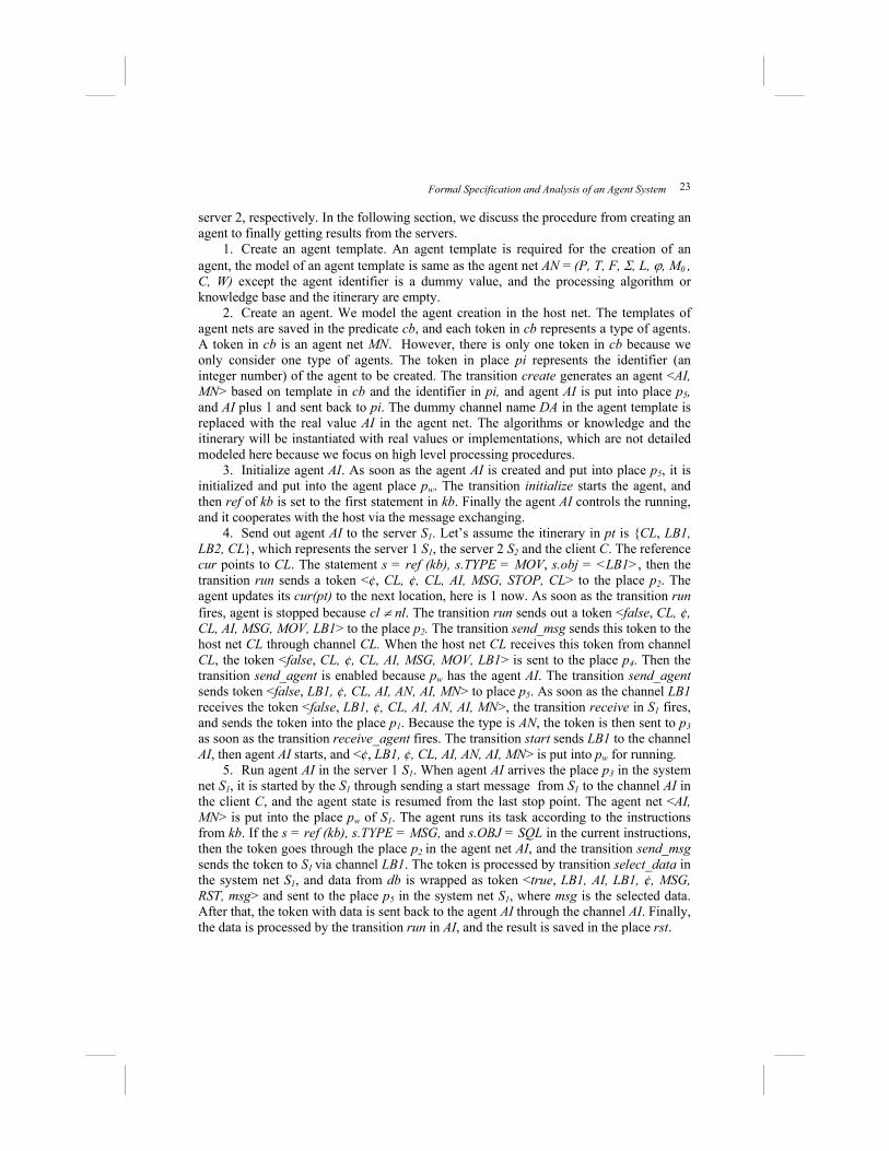
server 2, respectively. In the following section, we discuss the procedure from creating an agent to finally getting results from the servers.
1. Create an agent template. An agent template is required for the creation of an agent, the model of an agent template is same as the agent net AN = (P, T, F, Σ, L, ϕ, M0 , C, W) except the agent identifier is a dummy value, and the processing algorithm or knowledge base and the itinerary are empty.
2. Create an agent. We model the agent creation in the host net. The templates of agent nets are saved in the predicate cb, and each token in cb represents a type of agents. A token in cb is an agent net MN. However, there is only one token in cb because we only consider one type of agents. The token in place pi represents the identifier (an integer number) of the agent to be created. The transition create generates an agent <AI, MN> based on template in cb and the identifier in pi, and agent AI is put into place p5, and AI plus 1 and sent back to pi. The dummy channel name DA in the agent template is replaced with the real value AI in the agent net. The algorithms or knowledge and the itinerary will be instantiated with real values or implementations, which are not detailed modeled here because we focus on high level processing procedures.
3. Initialize agent AI. As soon as the agent AI is created and put into place p5, it is initialized and put into the agent place pw. The transition initialize starts the agent, and then ref of kb is set to the first statement in kb. Finally the agent AI controls the running, and it cooperates with the host via the message exchanging.
4. Send out agent AI to the server S1. Let’s assume the itinerary in pt is {CL, LB1, LB2, CL}, which represents the server 1 S1, the server 2 S2 and the client C. The reference cur points to CL. The statement s = ref (kb), s.TYPE = MOV, s.obj = <LB1>, then the transition run sends a token <¢, CL, ¢, CL, AI, MSG, STOP, CL> to the place p2. The agent updates its cur(pt) to the next location, here is 1 now. As soon as the transition run fires, agent is stopped because cl ≠ nl. The transition run sends out a token <false, CL, ¢, CL, AI, MSG, MOV, LB1> to the place p2. The transition send_msg sends this token to the host net CL through channel CL. When the host net CL receives this token from channel CL, the token <false, CL, ¢, CL, AI, MSG, MOV, LB1> is sent to the place p4. Then the transition send_agent is enabled because pw has the agent AI. The transition send_agent sends token <false, LB1, ¢, CL, AI, AN, AI, MN> to place p5. As soon as the channel LB1 receives the token <false, LB1, ¢, CL, AI, AN, AI, MN>, the transition receive in S1 fires, and sends the token into the place p1. Because the type is AN, the token is then sent to p3 as soon as the transition receive_agent fires. The transition start sends LB1 to the channel AI, then agent AI starts, and <¢, LB1, ¢, CL, AI, AN, AI, MN> is put into pw for running.
5. Run agent AI in the server 1 S1. When agent AI arrives the place p3 in the system net S1, it is started by the S1 through sending a start message from S1 to the channel AI in the client C, and the agent state is resumed from the last stop point. The agent net <AI, MN> is put into the place pw of S1. The agent runs its task according to the instructions from kb. If the s = ref (kb), s.TYPE = MSG, and s.OBJ = SQL in the current instructions, then the token goes through the place p2 in the agent net AI, and the transition send_msg sends the token to S1 via channel LB1. The token is processed by transition select_data in the system net S1, and data from db is wrapped as token <true, LB1, AI, LB1, ¢, MSG, RST, msg> and sent to the place p5 in the system net S1, where msg is the selected data. After that, the token with data is sent back to the agent AI through the channel AI. Finally, the data is processed by the transition run in AI, and the result is saved in the place rst.

24 J. Ding, X. He
6. Move agent AI to the server 2 S2. The procedure for moving the agent AI out is same as the procedure in 4, and the only difference is the destination is LB2 instead of LB1.
7. Run the agent in the server 2 S2. This procedure is same as the procedure in 5. 8. Move agent AI back to the client C. This procedure is same as the procedure in 4
except the destination is C. 9. Run agent AI in C. When agent AI returns to its home with the result, it is started
and put into the place pw of C. Then the agent AI sends a message with the result <false, CL, ¢, CL, AI, MSG, RST, msg> to the system C. As soon as C receives the message, it is forwarded to the place p4 of C, and then the transition save_rst processes the token and puts the result into the place p6.
4.5. Model Checking the MIP System using SPIN
In this section, we use the SPIN model checker to analyze the CPrT net models of the MIP system. We check agent or agent support system properties on the agent net, the host net and the system nets, while we check system properties on system-level nets, and interaction properties on the nets composing from agent nets and system nets.
4.5.1. Model checking a CPrT net using SPIN
SPIN is a generic automatic verification tool for formally analyzing the logical consistency of distributed systems, which are defined using Promela (PROcess MEta Language). SPIN reports deadlocks, unspecified receptions, flags incompleteness, race conditions, and unwarranted assumptions about the relative speeds of processes. SPIN has three basic functions: 1. As an exhaustive state space analyzer for rigorously proving the validity of user-specified correctness of requirements. 2. As a system simulator for rapid prototyping. 3. As a bit-state space analyzer that can validate large protocol systems with maximal coverage of the state space [16]. Promela is a verification modeling language with C programming language style, and it provides a way for making abstractions of distributed systems that suppress details that are unrelated to process interaction [16]. A Promela program consists of processes, message channels, and variables. Processes are global objects, and message channels and variables can be declared either globally or locally within a process. Processes specify behavior, channels and global variables define the environment in which processes run. Properties to be checked are declared as LTL (Linear Temporal Logic) formulae [16].
The SPIN Model checker only can directly check a model with finite states. In order to check an infinite state system using SPIN, we have to reduce the system model into a model with finite states. In many cases, some properties still hold after reducing a model with infinite states to a model with finite state. Therefore, we reduce models with infinite states into models with finite states as long as the reduction does not affect those properties we need to verify. In this paper, we model the software architecture of a mobile agent system using CPrT nets, but the input programs of SPIN are defined using Promela. We need to translate a CPrT net model into an equivalent Promela program. In order to verify different properties and reduce the complexity of the verification, SPIN checks the models based hierarchical analysis technique. SPIN first checks individual host net, system net, and agent net, and then verify system properties and interaction

Formal Specification and Analysis of an Agent System 25
properties on the model composing from system nets or system nets and agent nets. We provide a general procedure and rules for model checking a CPrT net model using SPIN.
Step 1: Reduce states (from infinite state model to finite state model) First we need to restrict each place p in a model is k-bounded (i.e. kpM ≤)( ,
M0[>M), where k is a constant. Then we define each variable type as an enumerable type with finite number of elements. The k is predefined according to system requirements.
Step 2: Specify properties After we defined system behavior models B using CPrT nets, we specify interested
system property specifications S using LTL. The verification procedure is to verify property specification S over behavior models B, i.e, SB =| .
Step 3: Translate a CPrT net model into a Promela program The following steps define the transformation rules. 3.1 Program structure. Each individual net in a CPrT net model is translated into a
process in Promela program. Each program includes type definitions, global variable declarations, processes, init process, and a never claim. The type definition defines places and variable types. The global variable declarations define global variables. Each process defines all transition relations in one net. The init process is used to assign the initial marking and other initial values. The never claim defines properties to be checked.
3.2 Defining state variables. Each place in a net is translated into a variable in Promela program. The value range of each variable represents the possible marking of the place. Therefore, the number of possible values of a variable is the number of possible markings of the corresponding place. If a place p is k-bounded and |φ(p)| is the number of possible values of a token in p, then the number of possible markings of place p is
∑ =
)(
0
p
iik
ϕ. Therefore, the declaration statement for place p has the form:
( )31..0:)(
0−∑=
p
iikp
ϕ
Thus, we treat a predicate symbol as a set of proposition symbols. This can be done when each p is bounded and |ϕ (p)| is finite [15].
3.3 Defining the initial state. Initialize each variable with a value, which is corresponding to the initial marking of the place in the behavior model. Initial variables are assigned values through init process in the Promela program. Each net has a corresponding process with its variables as input parameters, and init process invokes this process with real values (initial values). If there is more than one process in the program, and each one is corresponding to one subnet, then init process invokes these processes with their initial values as parallel running processes. The SPIN model checker guarantees the running fairness of these processes.
3.4 Defining transition relations. There are two types of transitions in CPrT nets, one is a transition that has not any channel, and another one is transition that has a channel. We discuss these two transitions separately.
• Defining a transition that has not any channel. Each transition in a CPrT net is defined as an atomic statement within a process in a Promela program. Each atomic statement defines the firing rules of the transition. The atomic statement consists of a series of case statements, and each one is corresponding to one possible input of the transition. The body of each case statement explicitly defines the translation from input to output. The number of case statement for each transition is the permutation number of input variables in inscription expressions of the input arcs of the transition.

26 J. Ding, X. He
• Defining a transition that has a channel. For each output channel, a global variable is declared in the Promela program for facilitating the synchronous communication between channels. Because the matched channels for the communication have to fire at the same time, the two transitions of the matched channels have to be translated into an atomic transaction, which defines the relationship between the input and the output of both transitions during they fire, in the Promela program. Therefore, for each output channel in the CPrT net model, it has to be translated into a Promela program with all possible matched input channels. Each atomic statement in the Promela program is defined for one possible match of the output channel and an input channel. The atomic statement for the possible matched channels consists of a series of case statements. Each case statement is corresponding to one possible input for the combing of the input channel and the output channel. Such as there is a transition t, which has an output channel mc (and one possible value of mc is C1), and there is another transition e, which has an input channel C1. Assume the inscription of t is φ(t), and the inscription of e is φ(e), and enabled_con(t) means the possible enabled input of t without considering the constraints on t, and enabled_con(e) means the possible enabled input of e without considering the constraints on e. The case statement has the following format.
atomic{ If ( enabled_con(t) && φ(t)\mc &&(mc = C1) && φ(e)\C1 && enabled_con(e)) {
Update the input and output of t after t fired; Update the input and output of e after e fired;
} If … …
} 3.5 Defining properties to be verified. We define never claim in Promela program to
verify properties, which are defined using LTL. never claims can be automatically generated from LTL formulae using SPIN tools. We also can define accept-state labels in Promela programs to check properties such as reachability. There are some other Promela constructs such as basic assertion, end-sate labels, progress-state labels, and trace assertions, which are also used to define interested properties in Promela programs.
4.5.2. Model checking the MIP system
In this section, we discuss how to analyze the CPrT net model of the MIP system using the SPIN model checker. The deadlock-free, reachability, and other important properties such as the interaction and synchronous communication are checked on different models. The CPrT nets to be checked include the system nets, the agent net, the interaction model composing from a system net and an agent net, and the system net composing from two system nets. For reason of simplicity but without losing the general meaning, we took away some unrelated information from the original CPrT net models considering the particular properties to be checked. The model checking was applied to simplified models, but even the simplified models are good enough to demonstrate the procedures and effectiveness of the analysis. The CPrT net models are transformed to Promela programs, and the properties are defined using LTL formulae.
The version and search information of the SPIN model checker we used is list in Figure 10.

Formal Specification and Analysis of an Agent System 27
Figure 10 Information on the SPIN used
(1) Model checking a system net
Figure 11 A simplified system net We chose the system net of the server 1 in the MIP system as an example. Figure 11 is the CPrT net model simplified from the original CPrT net model for the server 1 in the MIP system. The CPrT net model in Figure 11 is transformed to a Promela program, and the properties are defined using LTL formulae. The token structure in this system net: <dl, type, cmd>. Because we only consider receiving messages in this model without considering where they come from, we only need destination parameter dl. There are two types of messages: agents AN and regular message MSG. The cmd is the agent identifier if the message is an agent, or a MOV command.
Properties were checked: • If the system net receives a message from its channel, eventually, this message will
reach p4 or p6, • If the message received is a MOV command, the token in place p6 will be moved to
the place p0. The Results: All properties are valid
(2) Model checking an agent net
Figure 12 is the simplified net from the agent net in the MIP system. The token structure in this net is: <dl, da, cmd>. Each agent has its location, which is the identifier dl of its host net (or system net). Because we only consider receiving messages in this model without considering where they come from, we only need the destination parameter dl and da. The regular messages are the only type of messages in the agent net, but cmd could be STOP or other commands.
Spin Version 5.1.6 -- 9 May 2008) + Partial Order Reduction Full statespace search for: never claim + assertion violations + (if within scope of claim) acceptance cycles + (fairness enabled) invalid end states - (disabled by never claim)
LB1= dl
type = MSG
type = AN
cmd ≠ MOV
cmd= MOV
receive
receive msg
receive agent start agent
send
p6
p1 p5
p2
p3
p4
send_agent
send msgselect data
p0

28 J. Ding, X. He
Properties were checked: • If the agent net receives a message from its channel at the transition receive,
eventually, this message will reach p2 (i.e. the message is processed by the agent). • If the agent net receives the STOP command, then the agent can update its location
to the next location, (i.e., dl becomes dl +1). • As soon as the agent is sent out, the program updates its receiving channel cl to nl,
so that it simulates the dynamic migration property of an agent. The results: All properties are valid.
Figure 12 A simplified agent net
(3) Model checking the interaction properties
Figure 13 An interaction model of the MIP system
The interaction involves the synchronous communication between the agent and its
cmd≠ STOP
cmd = STOP
receive
(p6.dl = cl) run
cl ≠ nl
startp2
(cl = dl)&& (p0.da =DA) send_msg
stop_agent stop
p3
p1
p4 p5p6
p0
ps.dl= cl
type = MSG
type = AN
cmd ≠ MOV
cmd= MOV
receive
receive_msg
receive agent start agent
send
p6
p1 p5
p2
p3
p4
send_agent
send msgselect_data ps pa
p16
cmd≠ STOP
cmd = STOP
receive
(p6.dl = cl) run
cl ≠ nl
start p12
(cl = dl)&& (pa.da =DA)
send_msg
stop_agent stop
p13
p11
p14 p15 p16
pa
ps

Formal Specification and Analysis of an Agent System 29
support system. Therefore, the CPrT net model is a two-layer model composing from an agent net and its system net. Figure 13 is the interaction model that was checked. Before the agent is moved to place p6 in the system net, it is started through message passing from the system net to the agent net. As soon as the agent is started and moved to the place p6, the system sends a request to move it out. The moving is completed through two steps: first, the system sends a stop command to the agent to stop the execution of the agent; second, the agent updates its itinerary to the next destination and sends a message to the current system for migrating the agent to the next destination. As soon as the agent is moved out, the locations of the system net and the agent net are updated as the next destination so that the program can simulate the dynamic migration of mobile agents. The moving (such as stopping an agent, updating its location) and receiving agents (such as starting an agent) are completed with the collaborating between the agent and its system.
The token structure in this system net is: <dl, da, type cmd>, where dl is the location of current system and the agent (the first location is LB1 or CL), da is the agent identifier, type is the message type: which is an agent or a regular message, and cmd could be STOP, MOVE or agent identifier AI if the message is an agent. Because we only consider receiving messages in this model without considering where they come from, we only need destination parameter dl and da.
Properties were checked: • If the host net receives an agent, the agent will be started and put into the place p6. • An agent will be sent to its destination if the current system requests the agent to
be moved out. • As soon as the agent is sent out, the program updates the receiving channel cl and
dl to nl (nl is dynamically updated by the agent). The result: All properties are valid.
(4) Model checking the mobility properties
The mobility is checked on the system-level model without unfolding the agent nets because agent does not change its state or interact with other agents or systems during the migration. We abstract channels as regular places of two nets. Figure 14 is the system model composing from the two system nets.
The token structure in this system model is: <dl, sl, type cmd>, where dl is the destination location, sl is the source location (only two locations: LB1 and LB2), type is the message type: an agent or a regular message, and cmd could be STOP, MOVE or agent identifier AI if the message is an agent.
Properties were checked: • If the system net LB1 sends a message or an agent to destination system LB2,
eventually it will arrive at its destination LB2. • If the system net LB2 sends a message or an agent to destination host LB1,
eventually it will arrive at its destination LB1. The result: All properties are valid.

30 J. Ding, X. He
Figure 14 A system model of the MIP system
5. Summary and Future Work
In this paper, we extended PrT nets with dynamic channels for synchronous communication between transitions within different nets. In addition, we discussed how to introduce “nets within nets” modeling paradigm from EOS to PrT nets. CPrT nets not only provide the capability for modeling complex mobile computing systems with concise and comprehensive models, but also provide a solid foundation for formally analyzing mobile computing systems. A case study of a medical image processing system based on mobile agents was formally modeled using CPrT nets and analyzed using the SPIN model check. From successful modeling and analysis of mobile computing systems, we conclude that CPrT nets have the expressive power to naturally model and analyze the software architecture of mobile computing systems, and easily capture the properties especially the mobility, communication and dynamic configuration of the software architecture of mobile computing systems. Further research on modeling and analyzing the dynamic configuration of software architecture using CPrT nets is our current interesting topic.
Acknowledgements
This research was supported in part by the National Science Foundation of the USA under grant HRD-0317692, and by the National Aeronautics and Space Administration of the USA under grant NAG2-1440.
References
[1] Asperti, A., Busi, N., Mobile Petri Nets. Technical Report UBLCS-96-10, Laboratory for Computer Science, University of Bologna, Italy (1996)
LB1=pt. dl
type = MSG
type = AN
cmd ≠ MOV
cmd= MOV
receive
receive_msg
receive_agent start_agent
send
p6
p1 p5
p2
p3
p4
send_agent
send_msgselect_data pt1 ps
LB2=pt. dl
type = MSG
type = AN
cmd ≠ MOV
cmd= MOV
receive
receive_msg
receive_agent start_agent
send
p16
p11 p15
p12
p13
p14
send_agent
send_msg select_data pt ps1

Formal Specification and Analysis of an Agent System 31
[2] Chandy, K. M., and Misra, J., Parallel Program Design: A Foundation. Addison-Wesley, (1988)
[3] Christensen, S., Hansen, N.D., Coloured Petri Nets Extended with Channels for Synchronous Communication. In Proceeding of Application and Theory of Petri Nets (1994), pp. 159-178
[4] Ciancarini, P., Franze, F., and Mascolo, C., Using a Coordination Language to Specify and Analyze Systems Containing Mobile Components. ACM Trans. On Software Engineering and Methodology, vol. 9, no.2, (2000), pp. 167-198
[5] Clarke, E., The Birth of Model Checking, Grumberg, O., and Veith, H. (Eds.), 25Years of Model Checking, LNCS, vol. 5000, pp. 1–26, (2008)
[6] Clarke, E., Grumberg, Orna, and Peled, Doron A., Model Checking, The MIT Press, Cambridge, 1999
[7] Clarke, E., Long, D., McMillan, K., Compositional model checking, Proceedings of the Fourth Annual Symposium on Logic in computer science, (1989), pp. 353-362, Pacific Grove, CA, United States
[8] Fernandes, J.M., and Belo, O., Modeling Multi-Agent Systems Activities Through Colored Petri Nets, In Proceeding of 16th IASTED International Conference on Applied Informatics (AI’98), (1998), Germany, pp. 17-20,
[9] Fuggetta, A., Picco, G.P., and Vigna, G., Understanding Code Mobility. IEEE Trans. on Software Engineering, vol. 24 (1998), pp. 342-361
[10] Garlan, D., and Shaw, M., An Introduction to Software Architecture, Advances in Software Engineering and Knowledge Engineering, V. Ambriola, and G. Tortora eds, World Scientific Publishing Company, Singapore, (1993), pp. 1-39
[11] Genrich, H.J., and Lautenbach, K., System Modeling with High-level Petri Nets. Theoretical Computer Science, vol. 13 (1981), pp. 109-136
[12] Genrich, H.J., Predicate/Transition Nets. Petri Nets: Central Models and Their Properties, W. Brauer, W. Resig, and G. Rozenberg, eds., (1987) pp. 207-247
[13] Gluck, P.R., and Holzmann, G.J., Using SPIN model checking for flight software verification. IEEE Aerospace Conference Proceedings, vol. 1, (2002) pp. 105-113
[14] Gray, R.S. , Cybenko, G., Kotz, D., and Rus, D., Mobile Agents: Motivations and States of the Art, Handbook of Agent Technology, J. Bradshaw, ed., (2001)
[15] He, X., Yu, H., Shi, T., Ding, J., and Deng, Y., Formally Specifying and Analyzing Software Architectural Specifications Using SAM. Journal of Systems and Software, vol.71, no.1-2, pp.11-29, 2004
[16] Holzmann, G.J., The Spin Model Checker: primer and reference manual, Boston, MA. Addison-Wesley, 2003
[17] Kohler, M., Moldt, D., and Rolke, H., Modeling the behavior of Petri net agents. In J.M. Colom and M. Koutny, eds, LNCS, vol. 2705 (2001) pp. 224-241
[18] Kohler M., Moldt, D., and Rolke, H., Modeling mobility and mobile agents using nets within nets. In W.M.P. van der Aslst and E. Best, eds, LNCS, vol. 2769 (2003) pp.121-139
[19] Kohler, M., Rolke, H., Towards a Unified Approach for Modeling and Verification of Multi Agent Systems. Daniel Moldt, eds. MOCA'01 (2001) pp. 85-104
[20] Kummer, O., Simmulating synchronous channels and net instance. In J. Desel, P. Kemper, E. Kindler, and A. Oberweis, eds., 5. Workshop Algorithmen und Werkzeuge für Petrinetze, Forschungsbericht Nr. 694 (1998) pp. 73-78
[21] Kummer, O., and Wienberg, F., Renew – the reference net workshop. http://www.renew.de, (1999)
[22] Mascolo, C., Mobis: A Specification Language for Mobile Systems. In Proceeding of the Third Int’l Conf. Coordination Models and Languages (1999) pp. 37-52
[23] T. Murata, Petri Nets: Properties, Analysis and Applications, In Proceedings of the IEEE, vol.77, no.4, pp. 541-580 (1989)

32 J. Ding, X. He
[24] Milner, R., The Polyadic π-Calculus: a Tutorial. Hamer, Brauer, and Schwichtenberg, eds., Logic and Algebra of Specification, (1993) pp. 1-49
[25] Milner, R., Communicating and Mobile Systems: The π-Calculus. Cambridge University Press, (1999) New York
[26] Miyamoto, T., and Kumagai, S., A Multi Agent Net Model of Autonomous Distributed Systems, In Proceedings of CESA’96, Symposium on Discrete Events and Manufacturing Systems (1996) pp. 619-623,
[27] Moldt, D., and Wienberg, F., Multi-Agent-System based on Colored Petri Nets. LNCS, vol. 1248, (1997)
[28] Murata, T., Petri Nets: Properties, Analysis and Applications. In Proceedings of the IEEE, vol.77, no.4, (1989) pp. 541-580
[29] Păsăreanu, C. S.,Dwyer, M. B., Huth, M., Assume-Guarantee Model Checking of Software: A Comparative Case Study, LNCS, vol. 1680, (1999), pp. 168 – 183
[30] Păsăreanu,C. S., Giannakopoulou, D., Bobaru, M. G., Cobleigh, J. M., Barringer, H., Learning to divide and conquer: applying the L* algorithm to automate assume-guarantee reasoning, Formal Methods in System Design, Vol. 32, Issue 3 (2008), pp. 175 - 205
[31] Pingree, P.J., Mikk, E., Holzmann, G.J., Smith, M.H., and Dams, D., Validation of mission critical software design and implementation using model checking, In Proceedings of Digital Avionics Systems Conference, vol. 1, pp. 1-12, October 2002
[32] Roman, G.C., McCann, P.J., and Plun, J.Y., Mobile UNITY: Reasoning and Specification in Mobile Computing. ACM Trans. Software Engineering and Methodology, vol.6, no.3 (1997) pp. 250-282
[33] Serugendo, G.D., Muhugusa, M., A Survey of Theories for Mobile Agents. In World Wide Web Journal, special issue on distributed World Wide Web processing, applications and techniques of web agents, (1998)
[34] Shaw, M., The coming-of-age of software architecture research. In Proceedings of International Conference on Software Engineering. Toronto, (2001), pp. 656-664,
[35] Valk, R., Petri Nets as Toekn Objects, An Introduction to Elementary Object Nets. Jorg Desel, ed., LNCS, vol. 1420, Berlin (1998),
[36] Valk, R., Concurrency in Communication Object Petri Nets. F. DeCindio, G.A. Agha, and G. Rozenberg, eds., Concurrent Object-Oriented Programming and Petri Nets. LNCS (1999)
[37] Webb, Steve, The Physics of Medical Imaging, Institute of Physics Publishing, Philadelphia (1988)
[38] Xu, D., and Deng, Y., Modeling Mobile Agent Systems with High Level Petri Nets, In Proceeding of SMC’00 (2000), pp. 3177-3182
[39] Xu, D., Yin, J., Deng, Y. and Ding, J., A Formal Architecture Model for Logical Agent Mobility. IEEE Trans. on Software Engineering. vol.29, no. 1 (2003), pp. 31-45
[40] Xu, D., Nygard, K. E., Threat-Driven Modeling and Verification of Secure Software Using Aspect-Oriented Petri Nets, IEEE Trans. on Software Engineering. vol. 32, no. 4 (2006), pp. 265-278
[41] Xu, H., Shatz, S.M., A Framework for Model-Based Design of Agent-Oriented Software, IEEE Trans. on Software Engineering, vol. 29, no. 1, (2003) pp. 15-30
Copyright © 2022 FDOKUMEN