
Assisting Non-Experts in Property Specification for Automated Formal Verification
18
TRANSACTIONS ON SOFTWARE ENGINEERING, VOL. X, NO. X, XXXX 2015 1 Assisting Non-Experts in Property Specification for Automated Formal Verification Daniela Remenska, Tim A.C. Willemse, Jeff Templon, Kees Verstoep, and Henri Bal Abstract—Design errors in the development of concurrent software can result in deadlocks and race conditions, and discovering these is difficult. Rigorous analysis techniques such as model checking require the use of temporal logic to formalize application-specific properties and reason about the modeled system behavior. The well-established property patterns taxonomy captures requirements and contains useful mappings for different state-based target formalisms, but practitioners have to fully understand these patterns before they can select and apply the appropriate ones. To reassess the applicability of the pattern-based classification in an event-based setting, we examined 25 published works that use μ-calculus to express system properties from different domains. In the process of “patterning”, we encountered wrongly-formalized formulas in a number of them. Our findings indicate that manually eliciting properties is error-prone, and should be supported by more accessible tools. In our previous work, to bring the process of correctly eliciting functional properties closer to software engineers, we introduced PASS, a Property ASSistant, as part of a UML-based front-end to the mCRL2 model checking toolset. PASS instantiates pattern templates using three notations: a natural language summary, a μ-calculus formula and a UML sequence diagram depicting the desired behavior. Through a case study of a critical Grid module used by one of the CERN experiments, we demonstrate the usefulness of PASS in eliciting properties which capture the required behavior in real-world settings. We also introduce new patterns deemed useful, but missing from the original classification. Index Terms—Elicitation Tools, Formal methods, Specification techniques, Concurrency, Deadlocks, Modal logic ✦ 1 I NTRODUCTION D Esign errors in the development of concurrent soft- ware can result in deadlocks, livelocks, and race conditions, and discovering these is difficult. The sheer number of different executions and the inherent non- determinism in concurrent systems make complete test- ing of such software infeasible. Instead, more rigorous formal analysis techniques like model checking are re- quired, which systematically and possibly exhaustively analyze the behaviors of (an abstraction of) the system. Toolsets such as SPIN, nuSMV, CADP and mCRL2 offer such analysis techniques. Despite the research effort, these tools are still not widely accepted in industry. One serious obstacle is the effort required to master the underlying mathematical formalisms used for describing models in these toolsets. Bridging the gap between industry-adopted method- ologies based on UML software designs and the afore- mentioned tools and languages, in [1] we devised a methodology for automatically verifying UML models comprising sequence and activity diagrams. Figure 1 gives a general overview of the approach and imple- mented toolset. Any mature UML modeling tool can be used to obtain an XMI representation from the input model. The transformation rules define how to generate a model that conforms to the mCRL2 metamodel, from a model that conforms to the UML metamodel. Our proto- type uses the mCRL2 language [2] and toolset as a black box, without users having to leave the UML domain, except when describing application-specific properties. While the mCRL2 toolset can automatically discover Fig. 1. Automated verification of UML models deadlocks and search for specific events, its model check- ing facilities require users to formalize their application- specific properties in a data-enriched extension of the modal μ-calculus [3]. A downside is that it is not very accessible and requires a high degree of mathematical maturity. As already simpler languages such as Lin- ear Temporal Logic (LTL) and Computation Tree Logic (CTL) are not widespread in industry, the μ-calculus is unlikely to be embraced by the industry. In fact, most requirements are written in natural language, and often contain ambiguities which make it difficult even for experienced practitioners to capture them accurately in any temporal logic. There are subtle but crucial details which are often overlooked and need to be carefully considered in order to distill the right formula. In an attempt to ease the use of temporal logic, a pattern-based classification was developed in [4] for 0000–0000/00$00.00 c 2007 IEEE
Transcript of Assisting Non-Experts in Property Specification for Automated Formal Verification
TRANSACTIONS ON SOFTWARE ENGINEERING, VOL. X, NO. X, XXXX 2015 1
Assisting Non-Experts in Property Specificationfor Automated Formal Verification
Daniela Remenska, Tim A.C. Willemse, Jeff Templon, Kees Verstoep, and Henri Bal
Abstract—Design errors in the development of concurrent software can result in deadlocks and race conditions, and discovering theseis difficult. Rigorous analysis techniques such as model checking require the use of temporal logic to formalize application-specificproperties and reason about the modeled system behavior. The well-established property patterns taxonomy captures requirementsand contains useful mappings for different state-based target formalisms, but practitioners have to fully understand these patternsbefore they can select and apply the appropriate ones.To reassess the applicability of the pattern-based classification in an event-based setting, we examined 25 published works that useµ-calculus to express system properties from different domains. In the process of “patterning”, we encountered wrongly-formalizedformulas in a number of them. Our findings indicate that manually eliciting properties is error-prone, and should be supported by moreaccessible tools. In our previous work, to bring the process of correctly eliciting functional properties closer to software engineers, weintroduced PASS, a Property ASSistant, as part of a UML-based front-end to the mCRL2 model checking toolset. PASS instantiatespattern templates using three notations: a natural language summary, a µ-calculus formula and a UML sequence diagram depictingthe desired behavior. Through a case study of a critical Grid module used by one of the CERN experiments, we demonstrate theusefulness of PASS in eliciting properties which capture the required behavior in real-world settings. We also introduce new patternsdeemed useful, but missing from the original classification.
Index Terms—Elicitation Tools, Formal methods, Specification techniques, Concurrency, Deadlocks, Modal logic
F
1 INTRODUCTION
D Esign errors in the development of concurrent soft-ware can result in deadlocks, livelocks, and race
conditions, and discovering these is difficult. The sheernumber of different executions and the inherent non-determinism in concurrent systems make complete test-ing of such software infeasible. Instead, more rigorousformal analysis techniques like model checking are re-quired, which systematically and possibly exhaustivelyanalyze the behaviors of (an abstraction of) the system.Toolsets such as SPIN, nuSMV, CADP and mCRL2 offersuch analysis techniques. Despite the research effort,these tools are still not widely accepted in industry.One serious obstacle is the effort required to master theunderlying mathematical formalisms used for describingmodels in these toolsets.
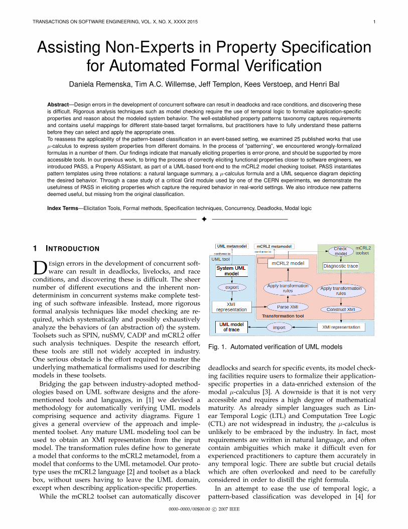
Bridging the gap between industry-adopted method-ologies based on UML software designs and the afore-mentioned tools and languages, in [1] we devised amethodology for automatically verifying UML modelscomprising sequence and activity diagrams. Figure 1gives a general overview of the approach and imple-mented toolset. Any mature UML modeling tool can beused to obtain an XMI representation from the inputmodel. The transformation rules define how to generatea model that conforms to the mCRL2 metamodel, from amodel that conforms to the UML metamodel. Our proto-type uses the mCRL2 language [2] and toolset as a blackbox, without users having to leave the UML domain,except when describing application-specific properties.
While the mCRL2 toolset can automatically discover
Fig. 1. Automated verification of UML models
deadlocks and search for specific events, its model check-ing facilities require users to formalize their application-specific properties in a data-enriched extension of themodal µ-calculus [3]. A downside is that it is not veryaccessible and requires a high degree of mathematicalmaturity. As already simpler languages such as Lin-ear Temporal Logic (LTL) and Computation Tree Logic(CTL) are not widespread in industry, the µ-calculus isunlikely to be embraced by the industry. In fact, mostrequirements are written in natural language, and oftencontain ambiguities which make it difficult even forexperienced practitioners to capture them accurately inany temporal logic. There are subtle but crucial detailswhich are often overlooked and need to be carefullyconsidered in order to distill the right formula.
In an attempt to ease the use of temporal logic, apattern-based classification was developed in [4] for
0000–0000/00$00.00 c© 2007 IEEE

TRANSACTIONS ON SOFTWARE ENGINEERING, VOL. X, NO. X, XXXX 2015 2
capturing requirements and generating input to modelchecking tools. The authors observed that almost all(> 500) properties they surveyed can be mapped intoone of several property patterns. Each pattern is a high-level, formalism-independent abstraction and capturesa commonly occurring requirement. Their hierarchicaltaxonomy is based on the idea that each pattern hasa scope, which defines the extent of program executionover which the pattern must hold, and a behavior, whichdescribes the intent of the pattern. The pattern systemidentifies 5 scopes and 11 behavior variations that canbe combined to create 55 different property templates.Examples of scopes are: globally, and after an eventor state occurs; examples of behavior classification are:absence (an event or state should never occur duringan execution) and response (an event or state must befollowed by another event or state).
Although the patterns website contains a collection ofmappings for different target formalisms such as LTLand CTL, in practice practitioners have to fully under-stand the classification before they can select and applythe appropriate pattern. To mitigate this problem, severalconversational tools [5], [6], [7] have been proposed forelucidating properties, based on the patterns. These toolsguide users in selecting the appropriate pattern andoptionally produce a formula in some target temporallogic.
Alternative approaches [8], [9], [10], [11], [12], [13],[14] tackle the property specification problem by propos-ing new graphical notations for specifying properties.As far as we have been able to trace, all approachesdeal with state-based logics. Such logics conceptuallydo not match the typical event-based UML sequencediagrams, in which events represent method calls orasynchronous communication between distributed com-ponents. A notable exception is [15], where an extensionof the alternation-free µ-calculus with action-based CTL-like formulas and regular expressions is introduced andimplemented within the CADP toolbox, allowing thedescription of safety, liveness and fairness properties viapredefined templates. However, no graphical notationsor tool support in the elicitation is provided in choosingthe right template for a particular property.
The contribution of our work is a simplification of theprocess of specifying functional requirements for event-based systems. Like the model, property specificationsneed to be understandable and accessible to non-experts,and at the same time mathematically precise to enableautomated analysis. In [16] we introduced PASS, a Prop-erty ASSistant tool that facilitates deriving system prop-erties. Based on natural language, PASS guides usersthrough the elicitation process by asking questions, andproviding a set of alternative answers to choose from,narrowing down the scope of the questions to those rele-vant in the context of the previously provided answers ineach subsequent step. Our starting point was the patternsystem [4] and the µ-calculus mappings [17] providedby the CADP team, which we extended with over 150
property templates. The pattern templates instantiatedwith PASS have three notations: a natural languagesummary, a µ-calculus formula and a UML sequence dia-gram depicting desired behaviors. The natural languagesummary is still readable for non-experts, while the µ-calculus formula can be given as input to the mCRL2toolset for model checking. Sequence diagrams providean intuitive level of abstraction for visualizing require-ments, by observing the sequence of method calls thatshould occur in a particular order at runtime. We utilizedmCRL2’s rich data extensions of the µ-calculus to expressdata-dependent properties. Lastly, for a fragment of ourproperties we automatically generate monitors, whichcan be used for property-driven on-the-fly verificationusing the standard exploration facilities of mCRL2. Ourmonitors are essentially sequence diagrams, acting asobservers of message exchanges.
We deliberately chose to develop PASS as an Eclipseplug-in, as our strong motivation was to stay within anexisting UML development environment, rather than usean external helper tool for this. This increases the tool’saccessibility by allowing software engineers to remainfocused in the realm of UML designs. In addition, a tightconnection between elements of the design and instancesof the property template is kept, such that, if the designis changed, these changes can be easily propagated inthe property template placeholders. To this end, we usethe standard MDT-UML2 [18] Eclipse modeling API.
This paper is an extension of [16] that makes thefollowing additional contributions:
• The property pattern mappings for µ-calculus havebeen further extended with new patterns incorpo-rated in PASS, which are deemed useful based onexperience, but were missing from the original clas-sification. We also elaborate on the applicability ofthese, as well as on the previous pattern extensionsin more depth.
• Through a case study of a critical Grid module(Storage Management System) used in productionby one of the CERN experiments, we demonstratethe applicability of PASS in eliciting propertieswhich capture the required behavior in real-worldsettings.
• 25 published works that use µ-calculus to expresssystem properties from different domains havebeen examined, for two purposes: to reassess theusefulness of the pattern-based classification inevent-based systems, with a focus on the µ-calculusas a target formalism, and to indicate how error-prone the manual elicitation of properties can be,even when it has been thoroughly reviewed. Thissurvey strengthens the claim of Dwyer et al. [4]that very few scopes and patterns are sufficientto express the majority of properties. From a totalof 178 properties encountered in the publications,around 70% could be fitted within the standardPSP classification. If our extensions are taken intoaccount, the coverage is improved by 10%. The
TRANSACTIONS ON SOFTWARE ENGINEERING, VOL. X, NO. X, XXXX 2015 3
results also illustrate that subtle mistakes can creepinto complex temporal logic formulas and poten-tially hide problems in the studied system model.We encountered 6 publications with wrong (or sub-optimal) property formalizations, where “wrong”means “not conveying the intention of the writtennatural language requirement”.
Structure. In Section 2 we discuss related approaches,and outline their advantages and shortcomings. Sec-tion 3 briefly introduces the basic Property SpecificationPatterns (PSP) classification. We describe our approachin Section 4, with focus on the pattern extensions. InSection 5 we apply PASS on a case study from theGrid domain. In Section 6 we report our findings ona large body of published work where properties in µ-calculus have been manually written, and we concludein Section 7.
2 RELATED WORK
PROPEL [5] is a tool that guides users in selecting theappropriate template from the patterns classification.PROPEL adds new patterns covering subtle aspects notaddressed by the patterns classification of [4] (such asconsidering the effect of multiple occurrences of a causein a response pattern); at the same time it omits otherimportant ones from the standard classification. Theresulting templates are represented using “disciplinednatural language” and finite state automata rather thantemporal logic expressions. Similar to PROPEL, the toolsSPIDER [6] and Prospec [7] extend the original patternsbut add compositionality. SPIDER is no longer main-tained nor available; the latest version of Prospec that wefound and tested produces formulas in Future IntervalLogic, not LTL as stated in [7].
Approaches that use a graphical notation for speci-fying properties come closest to the realm of modelingthe system behavior. In [9], formulas are representedas acyclic graphs of states and temporal operators asnodes. Technically, the underlying LTL formalism ishidden from the user, but the notation still closelyresembles the formalism. As such, it is not very ac-cessible. Another tool, called the TimeLine Editor [10]permits formalizing specific requirements using timelinediagrams. For instance, response formulas are depictedin timeline diagrams by specifying temporal relationsamong events and constraints. These diagrams are thenautomatically converted into Buchi automata, amenableto model checking with SPIN. Unfortunately the Time-Line Editor is no longer available. The CHARMY ap-proach [8] presents a scenario-based visual languagecalled Property Sequence Charts (PSC). Properties in thislanguage are relations on a set of exchanged systemmessages. The language borrows concepts from UML2.0 Sequence Diagrams and the tool uses SPIN as aback-end for model checking the generated Buchi au-tomata [19]. The PSC notation uses textual restrictionsfor past and future events, placed as circles directly onmessage arrows. A drawback of PSC is that it does
not support asynchronous communication, which is om-nipresent in concurrent systems. Furthermore, CHARMYis a standalone framework for architectural descriptions,not inter-operable with UML tools. As such, its use inindustrial contexts is limited.
Among the UML-based tools are HUGO/RT [11] andvUML [12]. HUGO/RT is a tool for model checking UML2.0 interactions against a model composed of message-exchanging state machines. The interactions representthe desired properties, and are translated together withthe system model into Buchi automata for model check-ing with SPIN. The version we tested supports no asyn-chronous messages nor combined fragments. vUML [12]is, like HUGO/RT, essentially a tool for automatingverifications of UML state machines. Properties must bespecified in terms of undesired scenarios. The verifica-tion is based on the ability to reach error states. This isinconvenient, as users must specify these manually. LiveSequence Charts (LSC) are also used [13], [14] as a graph-ical formalism for expressing behavioral properties. Theycan distinguish between possible (cold) and mandatory(hot) behaviors. For both, Buchi automata and LTL for-mulas are generated automatically from the diagrams.UML 2.0 sequence diagrams borrow many concepts fromLSC, by introducing the assert and negate fragmentscapturing mandatory and forbidden behavior. However,LSCs lack many UML features. Inspired by MessageSequence Charts, in [20] a visual language called EventSequence Charts with Quantitative Constraints (ESC-QC) is presented for specification of requirements inthe domain of embedded systems. ESC-QC specificationscan be translated into Simulink/Stateflow monitors andused for run-time verification of safety properties.
Resembling an OO programming language, UML’sproperty language OCL is considered for formal spec-ification purposes. However, constraints quickly becomequite dense and cryptic, and editing them manually iserror-prone. Another problem is the extent to whichdesigners are familiar with this language. Finally, OCL isby itself incapable of reasoning about temporal behavior.There are several temporal extensions of OCL. In [21]temporal modifiers @pre and @next are introduced forspecifying past and future state-oriented constraints.In [22], a real-time constraint extension of OCL is pro-posed for models described by UML state machines; itclaims to be able to describe all the existing patterns inthese OCL expressions. To simplify constraint definitionswith OCL, [23] proposes to use specification patterns forwhich OCL constraints can be generated automatically.The behavioral specification of software componentsrefers to interface specifications, which are not reallydynamic views. Moreover, this work does not introducemeans to specify temporal properties.
Finally, in the area of constructing specifications fromnatural language requirements, a recent ambitious workpresented in [24] attempts to combine the advantagesof model- and natural language-based requirements en-gineering. It proposes a methodology for bidirectional

TRANSACTIONS ON SOFTWARE ENGINEERING, VOL. X, NO. X, XXXX 2015 4
(a) Scopes
Behavior Property Patterns
Occurrence Order
Absence
Universality
Existence
Bounded
Existence
Precedence
Response
Precedence
Chain variants
Response
Chain variants
(b) Behaviors
Fig. 2. Property Specification Patterns: scopes (left) and behaviors (right)
translation between model-based requirements and con-trolled natural language (CNL) expressions with a re-stricted vocabulary. In particular, requirement patternsexpressed in CNL can be transformed into SysML in-ternal block diagrams and sequence diagrams, and viceversa. Although useful for property specification, thisapproach does not yet provide artifacts amenable forautomatic analysis and formal verification.
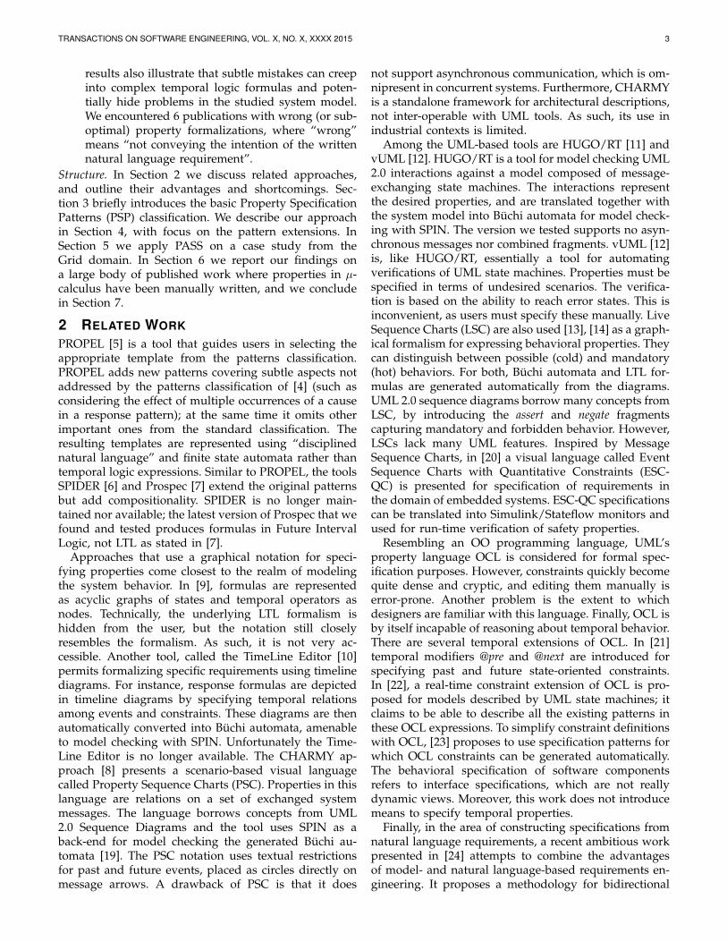
3 BACKGROUND:PROPERTY SPECIFICATIONPATTERNS
The PSP classification taxonomy [4] was developed as aresult of a large survey of formal property specifications,having recognized that they can be organized into sev-eral categories, based on two orthogonal concepts: theirscope and behavior. The patterns are general and can beapplied to events or states, depending on the formalismused for specification. In this work we are concernedwith event-based systems. The available scope intervalsfor a property are shown in Fig. 2(a). They can have abeginning, an ending delimiter, or both. In the figure, thehorizontal lines represent the model execution timelineduring which events occur. The vertical lines labeledwith Q and R denote events that mark the beginning andending of a scope respectively. If a property should holdthroughout the entire system execution, then there are nodelimiters (globally). The before-R scope restriction meansthat the behavior must hold before the first occurrenceof R. Similarly, after-Q requires that the behavior musthold after the first occurrence of Q. Between-Q-and-Ris a combination of the former two, i.e., the behaviormust hold after the first occurrence of Q until the firstsubsequent occurrence of R. If the occurrence of R isoptional, in the sense that the behavior must hold evenif R never happens, then the appropriate scope is after-Q-until-R.
The taxonomy organizes the behavior patterns(Fig. 2(b)) in two main categories: occurrence and order.Occurrence patterns are concerned with a single event,and are briefly described as follows. Absence: an eventmust never occur in the system execution; universality:an event must always occur in the system execution;existence: an event must eventually occur; bounded exis-tence: an event can occur at most k times in the systemexecution. Order patterns express properties where the
relative ordering of multiple events is important. Thetwo basic ones, precedence and response, are very commonin concurrent systems specifications. The chain variantscan be considered as generalizations of these, where theprecedence/response relationship consists of sequencesof more than two events. Precedence is used to specifythat the occurrence of one event is necessarily precededby an occurrence of another event. Response describesa cause-effect relationship: an occurrence of one eventmust be followed by an occurrence of another.
The available formalism-specific pattern mappings [4]smoothen the use of temporal logic for novices, butchoosing the right template is not always straightfor-ward. For example, consider the following requirement:
A component (C2) must eventually be started after thecomponent (C1) it depends on, is started.It can be instantiated as an existence pattern with anafter-Q scope, or as a response pattern with a globallyscope. Although both patterns describe related behavior,they are not equivalent. In the first case, the propertyis already satisfied if after the first start of C1, C2 isstarted once, and never again. On the other hand, thesecond property is satisfied if and only if every startof C1 is followed by a start of C2. The right choicealso depends on the domain knowledge (for example,whether components can be started/stopped multipletimes).
4 PASS: AN IMPLEMENTATION AND EXTEN-SION OF PSPIt has already been recognized that the process of“patterning“ the natural language requirements is stillchallenging. Case studies [25], [26] have indicated somedifficulties in introducing the PSP system in its currentform in the industrial process. There is a need for soft-ening the learning curve, preferably by accompanyingthe patterns with support material, such as graphicalrepresentations and examples. To describe our proposalto a correct and straightforward property elucidation, weoutline the motivations behind the choices we made, andhow they differ from existing related approaches.
While we follow on the idea of using a guidingquestionnaire to incrementally refine various aspectsof a requirement, we find the resulting artifacts (LTL
TRANSACTIONS ON SOFTWARE ENGINEERING, VOL. X, NO. X, XXXX 2015 5
formulas or graphical representations of finite state ma-chines) from using the available tools not yet suitablefor practical application in our context. For one, thepractitioner must manually define the events to be as-sociated with the placeholders when instantiating thetemplate. To avoid potential errors, as well as reducethe effort of specifying, we want to ideally stay inthe same IDE used for modeling the system, and onlyuse existing events that represent valid communicationbetween components.
4.1 µ-calculus and the PSP systemMost approaches cover the (state-based) LTL mappingsand extensions of the pattern system. Event-based tem-poral logics have not received much attention. Eventhough the original pattern system does not cover µ-calculus, such mappings [17] have been developed bythe CADP team, but their effectiveness has not been es-tablished. These are adequate for action- or event-basedsystems, making them a good match for visual scenarios,where communication between components is depicted.LTL is interpreted over Kripke structures, where thestates are labeled with elementary propositions that holdin each state, while µ-calculus is interpreted over La-beled Transition Systems (LTS), in which the transitionsare labeled with actions that cause state changes. Eventhough both are complementary representations of themore general finite state automata, conversions betweenthem are not practical, as they usually lead to a signifi-cant state space increase. For example, the fact that a lockhas been acquired or released can be naturally expressedby actions. Since state-based temporal logics lack thismechanism, an alternative is to introduce a variableto indicate the status of the lock, i.e., expose the stateinformation. With such properties, LTS representationsare more intuitive, and easier to query using event-basedlogics. LTS structures provide the formal operationalsemantics for behaviors described with process algebras,such as mCRL2.
Brief Introduction to µ-calculusmCRL2 is a language and accompanying toolset for spec-ifying and analyzing concurrent systems. Our choice forusing the mCRL2 language as a back-end is motivatedby its rich set of abstract data types as first-class citi-zens, as well as its powerful, actively maintained toolsetfor analyzing, simulating, and visualizing specifications.The language used by the mCRL2 toolset for modelchecking specific properties is an extension of the modalµ-calculus [27]. It is a language for reasoning aboutevent- and state-based properties of event-based modelswritten in process algebra. This formalism stands outfrom most modal and temporal logic formalisms withrespect to its expressive power. Temporal logics like LTL,CTL and CTL* all have succinct translations [28] intoµ-calculus, witnessing its generality. This expressivenesscomes at a cost: very complex formulas with no intuitiveand apparent interpretation can be coined. The syntax of
mCRL2’s modal µ-calculus formulas we are concernedwith in this paper is defined by the following grammar:
φ ::= b | φ ∧ φ | φ ∨ φ | ∀d:D.φ | ∃d:D.φ |[R]φ | 〈R〉φ | µZ. φ(Z) | νZ. φ(Z)
R ::= α | R ·R | R∗ | R+
α ::= b | a(d1, . . . , dn) | ¬α | α ∩ α | α ∪ α |⋂d:D.α |
⋃d:D.α
Actions represent observable atomic events in themodel. Action formulas describe sets of actions; thesesets are built up from the empty set of actions (in caseBoolean expression b evaluates to false), the set of allpossible actions (in case Boolean expression b evaluatesto true), individual actions a(d1, . . . , dn), action comple-mentation and finite and possibly infinite intersection ∩and union ∪. The action formula
⋃d:D.α(d) represents
the set of actions {α(d) | d:D}. The modal operators takeregular expressions R for describing words of actions,built up from individual actions described by an actionformula α, word concatenation R · R and (arbitrary)iteration of words R∗ and R+. Properties are expressedby state formulas φ, which contain Boolean data termsb that evaluate to true or false and which can containdata variables, the standard logical connectives and (∧)and or (∨), the modal operators must ([ ] ) and may(〈 〉 ), and the least and greatest fixpoint operators µand ν. In addition to these, mCRL2’s extensions adduniversal and existential quantifiers ∀ and ∃. A stateof an LTS (described by an mCRL2 process) satisfies〈R〉φ iff from that state, there is at least one transitionsequence matching R, leading to a state satisfying φ;[R]φ is satisfied by a state iff all transition sequencesmatching R starting in that state lead to states satisfyingφ. For instance, [¬(
⋃n:Nat. read(n+ n))]false states that
a process should not execute any actions other than readactions with even-valued natural numbers. Note that[a]φ is trivially satisfied in states with no “a”-transitions.
Combining these modalities, the least (µX. φ(X)) andgreatest (νX. φ(X)) fixpoints permit reasoning aboutfinite and infinite runs of a system in a recursion-likemanner. For example, we can read µX. φ ∨ 〈α〉X as: Xis the smallest set of states such that a state is in X iffφ holds in that state or there is an α-successor in X . Onthe other hand, νX. φ ∧ [α]X is the largest set of statessuch that a state is in X iff φ holds in that state and allof its α-successors are in X , too.
In mCRL2, verification of µ-calculus formulas is con-ducted using tooling that operates on systems of fix-point equations over first-order logic expressions. Thissometimes requires too much overhead to serve as abasis for lightweight bug-hunting, as it can be difficultto interpret the counterexamples that are obtained fromthese equation systems in terms of the original mCRL2process. Observers, or monitors (a la Buchi) definedin the mCRL2 model itself, can sometimes be used tobypass the problem (see [16]).
TRANSACTIONS ON SOFTWARE ENGINEERING, VOL. X, NO. X, XXXX 2015 6
TABLE 1After-Q vs. After-Last-Q scope variations for different behavior patterns
Behavior After-Q After-Last-QAbsence [(¬Q)∗. Q. true∗. P ]false [true∗. Q. (¬Q)∗](([true∗. Q]false )⇒ [true∗. P ]false)
Existence [(¬Q)∗. Q]µX.(〈true〉true ∧ [¬P ]X) [true∗. Q. (¬Q)∗](([true∗. Q]false)⇒ µX.(〈true〉true ∧ [¬P ]X))
Precedence [(¬Q)∗. Q. (¬P )∗. S]false [true∗. Q. (¬Q)∗]((true∗. Q]false)⇒ [(¬P )∗. S]false)
Response [(¬Q)∗. Q. true∗. P ]µX.〈true〉true ∧ [¬S]X [true∗. Q. (¬Q)∗](([true∗. Q]false)⇒ [true∗. P ](µX.〈true〉true ∧ [¬S]X))
Pattern Mappings for µ-calculus
To get an impression of the µ-calculus pattern map-pings [17], we illustrate some commonly used templates.Basic safety properties are generally expressed using thebox (must) modality containing regular formulas. Forexample, the precedence pattern with a global scope ischaracterized in the following way:
[(¬S)∗. P ]false
To specify that a memory cleanup must occur before theprogram shutdown, the generic event placeholders S andP should be substituted with the actual events:
[(¬clean memory)∗. program shutdown]false
The formula states that the process should never exhibita behavior in which a program shutdown event is pre-ceded by an arbitrary number of events, none of whichmatches clean memory. An after-Q scope restriction of thesame pattern has the following template:
[(¬Q)∗. Q. (¬S)∗. P ]false
The regular expression has been modified to consumeall events up to the point of the occurrence of Q.
Liveness1 properties typically make use of the dia-mond (may) modality and fixed point operators. Forinstance, the response pattern with a global scope is ex-pressed as follows:
[true∗. P ] µX.〈true〉true ∧ [¬S]XThe template can be instantiated to state that after everysend event, all execution sequences will eventually leadto the receive event:
[true∗. send] µX.〈true〉true ∧ [¬receive]XAn after-Q scope restriction of the same pattern has thefollowing template:
[(¬Q)∗. Q. true∗. P ] µX.〈true〉true ∧ [¬S]X
4.2 Pattern Extensions
The PSP authors recognized that variations of the pro-posed scopes and behaviors may be necessary in cer-tain cases, and provided basic notes on how to modifythe specifications for some of them. To improve ex-pressiveness without users having to manually tailortheir formulas, we have incorporated several patternextensions in PASS, which were also absent from the µ-calculus mappings [17] provided by CADP. For instance,by default the scopes are interpreted with respect tothe first occurrence of the beginning scope delimiter.
1. Properties that require that “something good eventually happens”.The existence and response patterns are an example. Contrary to these,safety properties require that “something bad never happens”. All non-trivial functional properties can be classified as safety, liveness, or a mixof these two.
Subsequent occurrences of that event are ignored untilthe occurrence of the end-delimiter closes the interval.Consider the following property:
After the last bid, the product is paid by the winner.Online auction systems typically receive bids from mul-tiple customers, but only the last one matters, before theauction closes. In such case, there should be an optionwhere the beginning of the scope is essentially reset withevery new occurrence of the event Q. We provided ascope variation after-last-Q and a similar option for thebetween-Q-and-R scope. Table 1 illustrates how the scopewas adapted for some of the behaviors. Furthermore,the original taxonomy does not clarify how to treata behavior combined with a before-R scope restriction,if the event R does not happen until the end of thesystem execution. For such a case, the default semanticsprovided in [17] are that the specified behavior is notrequired to hold, i.e., the property is trivially (vacuously)satisfied unless the end-event R is seen. A variation(after-Q-until-R) was only provided for the between-Q-and-R scope. Consider the following property:
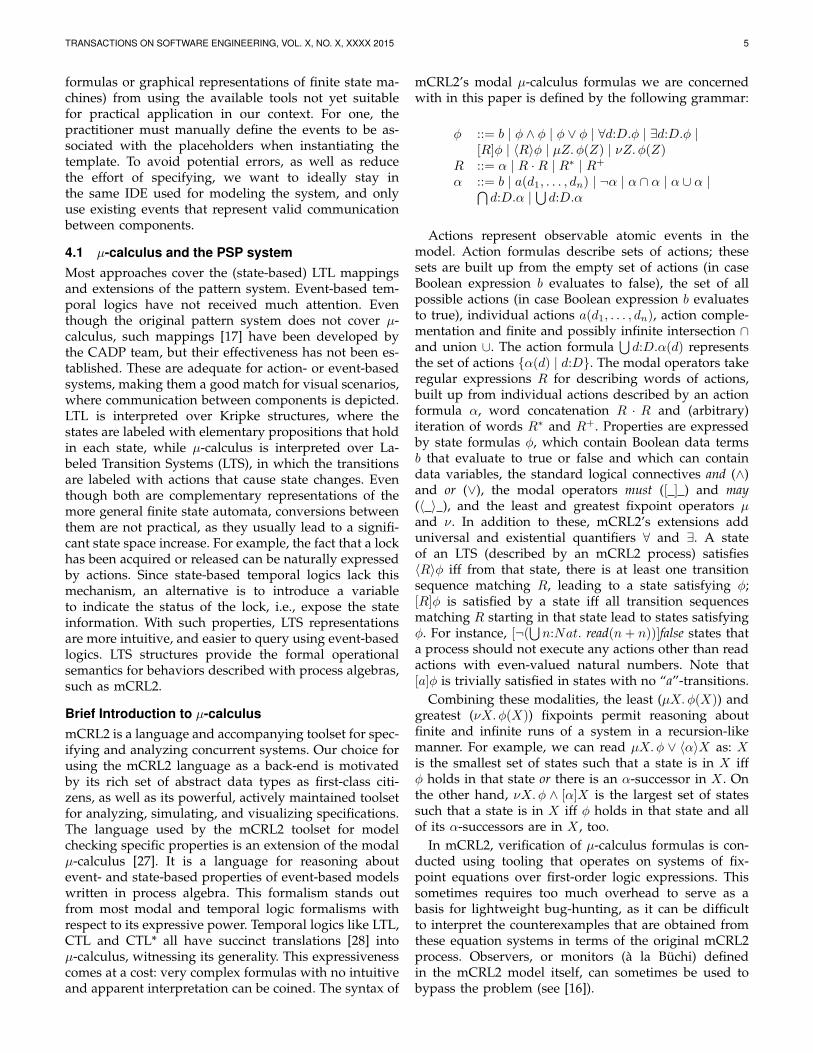
A student cannot take an exam before taking the course.If the course is optional, then the event of taking a coursemay also not happen, so the behavior (“a student cannottake the exam”) must hold until either taking the course,or until the end of the run if the course is not taken.We kept the default semantics and provided an optionto select an until-R scope variation. The added scopevariations are shown in Fig. 3(a).
Given that communication among components pro-ceeds via actions (or events) which can represent syn-chronous or asynchronous communication, propertyspecification can be defined over sequences of actionsthat are data-dependent. Fortunately, the mCRL2 µ-calculus is rich enough to express both state and actionformulas, and provides means for quantification overdata, which many formalisms lack. With our approach,a practitioner can use a wildcard “*” to express thatthe property should be evaluated for all values thatmessage parameters can carry. This allows us to usepatterns which would otherwise make sense only forstate-based formalisms. For example, in its original form,the universality behavior pattern describes a portion ofthe system’s execution which contains only states/eventsthat have a desired property. In event-based systems thiswould directly translate to “an event must always occur inthe system execution”, which is not a very useful propertyfor a system to exhibit, since it means that there is onlyone possible event always taking place. Even thoughthis pattern is provided as such in [17], a more practical

TRANSACTIONS ON SOFTWARE ENGINEERING, VOL. X, NO. X, XXXX 2015 7
Until-R
(a) Scopes
Behavior Property Patterns
Occurrence Order
Absence
Universality
Existence
Bounded
Existence
Precedence
Response
Precedence
Chain variants
Response
Chain variants
Always-EnabledPrecedence
variantExistence
Under Fairness
Assumption
Response
variantResponse
Under Fairness
Assumption
Response variant
Under Fairness
Assumption
(b) Behaviors
Fig. 3. Pattern Extensions incorporated in PASS
alternative is checking if an event always carries thesame data value, so we refined it in this context. Forcomparison, the provided pattern template for a globalscope is:
[true∗.¬P ]false
which means that at most event P can happen at anymoment, while:
[true∗] ∀d :D.(d 6= d1) ⇒ [P (d)]false
means that the event P can only carry a data valued1. Related to this pattern, an interesting and realisticproperty is to ask if some event is always possible(or enabled), rather than always taken. For example,“it should always be possible to exit a program”. For thispurpose, we have added the always-enabled pattern. Forexample:
[(¬initialize)∗. initialize. true∗]〈exit〉truemeans that at any point after initialization, the exit eventis enabled.
Models usually abstract away from the underlying OSscheduling policy, containing no information on howoften a process is executed, or how the next process tobe executed is chosen; the scheduler is treated nonde-terministically. The effect of this choice is that there canbe traces in the LTS representation of the model that donot correspond to realistic scenarios, for example, runsin which a single process gets all execution time. Unlessthe scheduler is explicitly modeled, we often want todisregard such unrealistic loops, since they may leadto false-negatives: unrealistic counter-examples whenmodel checking liveness properties. To disregard suchbehavior, we have added fairness variants of the existenceand response patterns, which rely on the assumption thatin reality each process of the system is given a fair chanceto execute.
Inspired by [5], further variants of the precedence andresponse patterns have also been added to PASS. Forexample, consider the following property:
Every request for the resource is eventually acknowledged.Also, a request must eventually arrive in a correctly function-ing system.There is an additional constraint to this response property,namely, that the cause event must take place. Takinginto account a similar consideration, a precedence variant
is added. All behavior extensions are shown in 3(b).Adding 4 scope and 6 behavior variations have ledto more than 150 ((5+4)∗(11+6)) unique patterns to bechosen from.
4.3 UML Sequence DiagramsIn our experience, visual scenarios are the most suitableand commonly used means to understand the dynamicsof a system. We believe that such a visual depiction ofa scenario, more than finite state machines, improvesthe practitioner’s understanding of the requirement aswell. This is why we chose sequence diagrams as aproperty specification artifact too. A controlled experi-ment study [29] has also concluded that the presence ofsequence diagrams significantly improves the compre-hension of the modeled functional requirements.
Sequence diagrams model the interaction among a setof components, emphasizing the sequence of messagesexchanged over time. They have been extended con-siderably in UML 2.x to allow expressing of complexcontrol flows such as branching, iterations, and referringto existing interactions. Combined fragments are usedfor this purpose. The specification supports differentfragment types, with operators such as alt, opt, loop,break, par. Each combined fragment consists of one ormore interaction operands. Depending on the type of thefragment, constraints can guard each of the interactionoperands. Combined fragments can be nested with anarbitrary nesting depth, to capture complex workflows.Figure 4 shows how some of them can be used. Thereare also two less-known combined fragments: assert andnegate. Their use in practice is limited, because their
Fig. 4. Sequence diagrams with combined fragments
TRANSACTIONS ON SOFTWARE ENGINEERING, VOL. X, NO. X, XXXX 2015 8
semantics described in the UML 2.0 superstructure spec-ification [30] are somewhat vague and confusing. Bydefault, sequence diagrams without the use of these twooperators only reflect possible behavior, while assert andnegate alter the way a trace can be classified as validor invalid. The specification characterizes the semanticsof a sequence diagram as a pair of valid and invalidsets of traces, where a trace is a sequence of eventsor messages. The potential problems with the UML 2.0assertion and negation are explained in [31]. In summary,the specification aims at depicting required and forbid-den behaviors. However, as [31] points out, stating that“the sequences of the operand of the assertion are theonly valid continuations. All other continuations resultin an invalid trace” suggests that the invalid set of tracesfor an assert fragment is its complement, i.e., the set ofall other possible traces. Conversely, the standard alsodeclares that the invalid set of traces are associated onlywith the use of a negate fragment, which is contradictorywith the previous statement. We believe that these twooperators should be considered as truth modalities, andwe assign the following semantics: negate is considereda set-complement operator for the event captured by thefragment, while assert specifies that an event must occur.For the reasons described above, we disallow nestingbetween these two fragments. We find that this doesnot limit the expressiveness of property specifications inpractice.
Most of the invented notations used by existing sce-nario approaches can fit well in UML 2.0 sequencediagrams. Profiles are a standard way to extend UMLfor expressing concepts not included in the official meta-model. In short, UML profiles consist of stereotypes thatcan be applied to any UML model element, like classes,associations, or messages. We used this mechanism toapply the restrictions on the usage of negate and assert,as well as to distinguish events representing intervalbounds from regular ones. As an example, Fig. 5(a) de-
(a) UML2 Sequence Dia-gram with applied stereo-types
(b) Property Sequence Chart [8]
Fig. 5. Scenarios for the precedence chain pattern with aBetween-Q-And-R scope
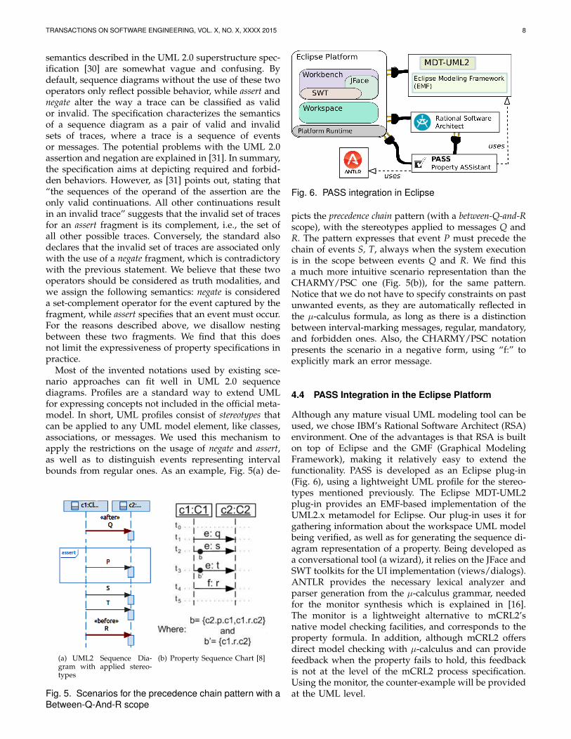
Fig. 6. PASS integration in Eclipse
picts the precedence chain pattern (with a between-Q-and-Rscope), with the stereotypes applied to messages Q andR. The pattern expresses that event P must precede thechain of events S, T, always when the system executionis in the scope between events Q and R. We find thisa much more intuitive scenario representation than theCHARMY/PSC one (Fig. 5(b)), for the same pattern.Notice that we do not have to specify constraints on pastunwanted events, as they are automatically reflected inthe µ-calculus formula, as long as there is a distinctionbetween interval-marking messages, regular, mandatory,and forbidden ones. Also, the CHARMY/PSC notationpresents the scenario in a negative form, using “f:” toexplicitly mark an error message.
4.4 PASS Integration in the Eclipse Platform
Although any mature visual UML modeling tool can beused, we chose IBM’s Rational Software Architect (RSA)environment. One of the advantages is that RSA is builton top of Eclipse and the GMF (Graphical ModelingFramework), making it relatively easy to extend thefunctionality. PASS is developed as an Eclipse plug-in(Fig. 6), using a lightweight UML profile for the stereo-types mentioned previously. The Eclipse MDT-UML2plug-in provides an EMF-based implementation of theUML2.x metamodel for Eclipse. Our plug-in uses it forgathering information about the workspace UML modelbeing verified, as well as for generating the sequence di-agram representation of a property. Being developed asa conversational tool (a wizard), it relies on the JFace andSWT toolkits for the UI implementation (views/dialogs).ANTLR provides the necessary lexical analyzer andparser generation from the µ-calculus grammar, neededfor the monitor synthesis which is explained in [16].The monitor is a lightweight alternative to mCRL2’snative model checking facilities, and corresponds to theproperty formula. In addition, although mCRL2 offersdirect model checking with µ-calculus and can providefeedback when the property fails to hold, this feedbackis not at the level of the mCRL2 process specification.Using the monitor, the counter-example will be providedat the UML level.
TRANSACTIONS ON SOFTWARE ENGINEERING, VOL. X, NO. X, XXXX 2015 9
5 PASS BY EXAMPLE: REVISITING DIRACWe demonstrate the applicability of PASS for elicitingproperties by examining a misbehaving grid module ofthe DIRAC system used by one of the CERN experi-ments. DIRAC [32] is the community grid framework forjob and data management used to support productionand user activities of the LHCb experiment. Its architec-ture is organized around two main component types:services and agents. Services are passive componentsthat react to requests from clients, possibly solicitingother services in order to fulfill the requests. They run aspermanent processes and store system state informationin databases. The user interfaces, agents or running jobscan act as clients. Agents are lightweight active com-ponents that fulfill some limited system functionality.Having specific missions, DIRAC agents repeat their im-plemented logic in iteration cycles. By placing requeststo the services, they monitor the states of various systementities and initiate actions (like job submission or datatransfer), which can in turn update these states.
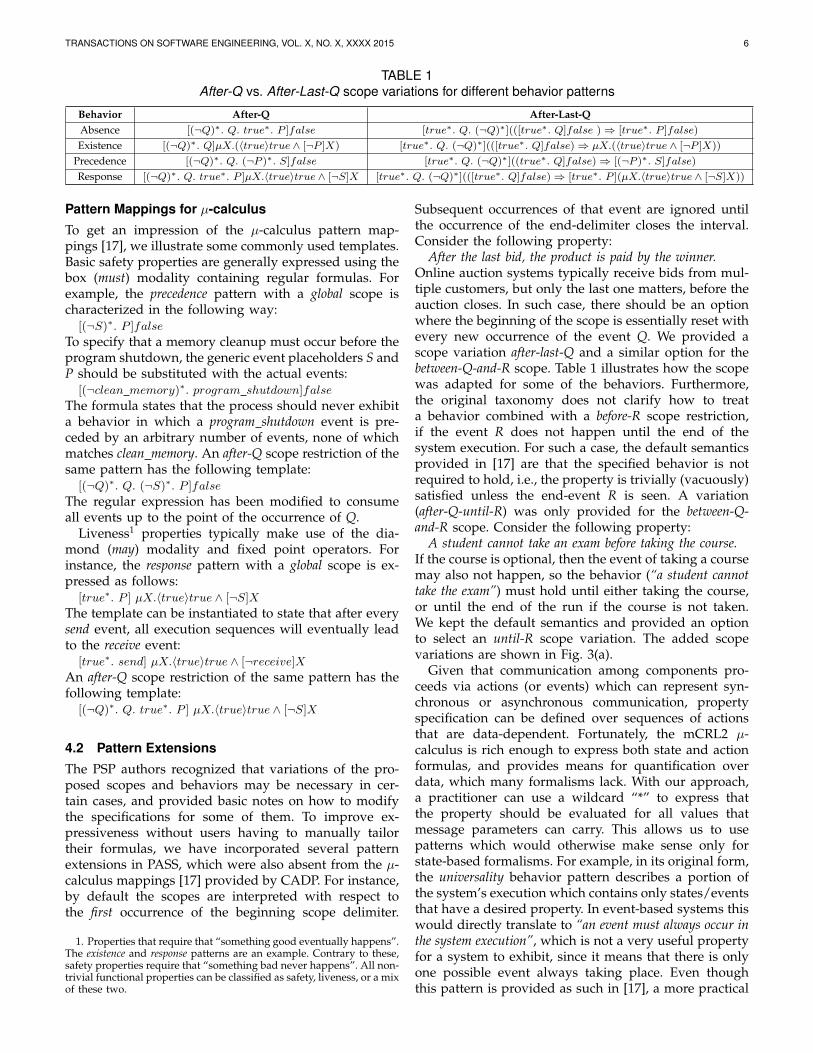
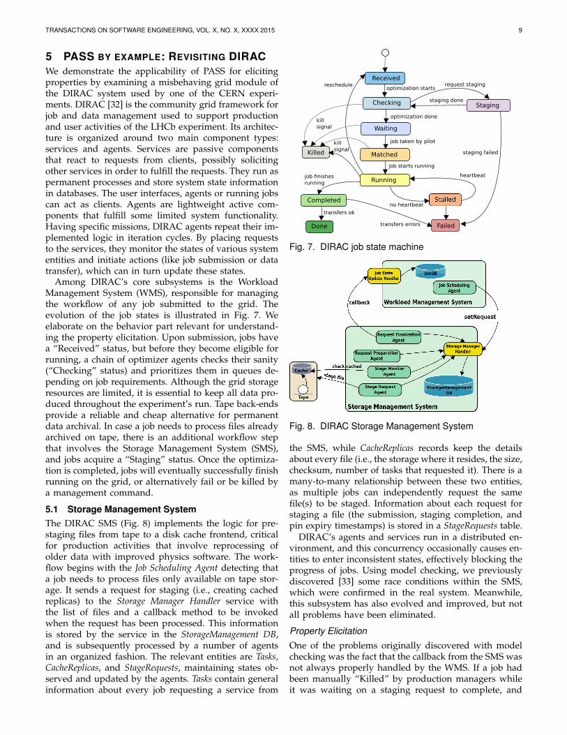
Among DIRAC’s core subsystems is the WorkloadManagement System (WMS), responsible for managingthe workflow of any job submitted to the grid. Theevolution of the job states is illustrated in Fig. 7. Weelaborate on the behavior part relevant for understand-ing the property elicitation. Upon submission, jobs havea “Received” status, but before they become eligible forrunning, a chain of optimizer agents checks their sanity(“Checking” status) and prioritizes them in queues de-pending on job requirements. Although the grid storageresources are limited, it is essential to keep all data pro-duced throughout the experiment’s run. Tape back-endsprovide a reliable and cheap alternative for permanentdata archival. In case a job needs to process files alreadyarchived on tape, there is an additional workflow stepthat involves the Storage Management System (SMS),and jobs acquire a “Staging” status. Once the optimiza-tion is completed, jobs will eventually successfully finishrunning on the grid, or alternatively fail or be killed bya management command.
5.1 Storage Management SystemThe DIRAC SMS (Fig. 8) implements the logic for pre-staging files from tape to a disk cache frontend, criticalfor production activities that involve reprocessing ofolder data with improved physics software. The work-flow begins with the Job Scheduling Agent detecting thata job needs to process files only available on tape stor-age. It sends a request for staging (i.e., creating cachedreplicas) to the Storage Manager Handler service withthe list of files and a callback method to be invokedwhen the request has been processed. This informationis stored by the service in the StorageManagement DB,and is subsequently processed by a number of agentsin an organized fashion. The relevant entities are Tasks,CacheReplicas, and StageRequests, maintaining states ob-served and updated by the agents. Tasks contain generalinformation about every job requesting a service from
Checking
Received
Waiting
Failed
Stagingstaging done
Matched
Running
Completed
Done
staging failed
reschedule
optimization done
request staging
job taken by pilot
job starts running
optimization starts
heartbeatjob finishes
running
transfers errors
transfers ok
no heartbeat
Killed
kill
signal
kill
signal
Fig. 7. DIRAC job state machine
Job State
Update Handler
Fig. 8. DIRAC Storage Management System
the SMS, while CacheReplicas records keep the detailsabout every file (i.e., the storage where it resides, the size,checksum, number of tasks that requested it). There is amany-to-many relationship between these two entities,as multiple jobs can independently request the samefile(s) to be staged. Information about each request forstaging a file (the submission, staging completion, andpin expiry timestamps) is stored in a StageRequests table.
DIRAC’s agents and services run in a distributed en-vironment, and this concurrency occasionally causes en-tities to enter inconsistent states, effectively blocking theprogress of jobs. Using model checking, we previouslydiscovered [33] some race conditions within the SMS,which were confirmed in the real system. Meanwhile,this subsystem has also evolved and improved, but notall problems have been eliminated.
Property Elicitation
One of the problems originally discovered with modelchecking was the fact that the callback from the SMS wasnot always properly handled by the WMS. If a job hadbeen manually “Killed” by production managers whileit was waiting on a staging request to complete, and
TRANSACTIONS ON SOFTWARE ENGINEERING, VOL. X, NO. X, XXXX 2015 10
the callback from the SMS arrived only later, it wouldawaken the job and cause it to eventually start running.Such “zombie” jobs were discovered in the system onseveral occasions, and a simple fix was implementedin the WMS to properly guard the callback against thisparticular case. Reflecting this change in the model, itwas confirmed that the SMS callback no longer affectedthe job state if the original “Staging” one had changedto some other status in the meantime. However, anotherproblem appeared later in production. Jobs would re-main in a “Staging” state without progress, and anystaging request information was apparently already gonefrom the SMS, making it difficult to investigate the rootcause based solely on logging traces analysis. To capturethe underlying problem formally for the purpose ofmodel checking, we established the following informalproperty statement: any job requesting staging must even-tually make progress (the job must be called-back properly)before the corresponding task is removed from the SMS.
5.2 PASS: The Property ASSistant
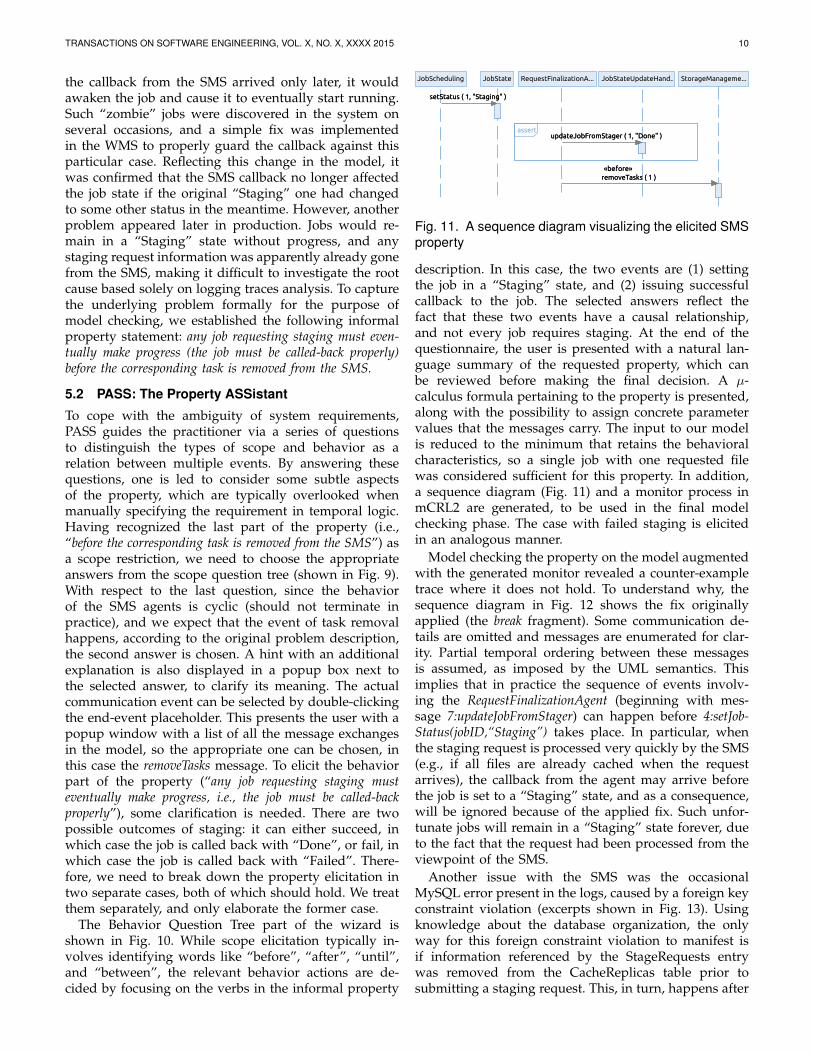
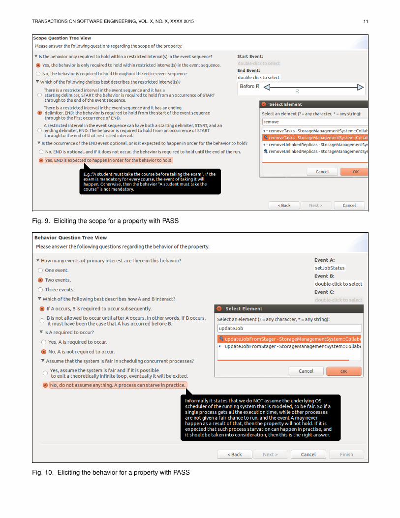
To cope with the ambiguity of system requirements,PASS guides the practitioner via a series of questionsto distinguish the types of scope and behavior as arelation between multiple events. By answering thesequestions, one is led to consider some subtle aspectsof the property, which are typically overlooked whenmanually specifying the requirement in temporal logic.Having recognized the last part of the property (i.e.,“before the corresponding task is removed from the SMS”) asa scope restriction, we need to choose the appropriateanswers from the scope question tree (shown in Fig. 9).With respect to the last question, since the behaviorof the SMS agents is cyclic (should not terminate inpractice), and we expect that the event of task removalhappens, according to the original problem description,the second answer is chosen. A hint with an additionalexplanation is also displayed in a popup box next tothe selected answer, to clarify its meaning. The actualcommunication event can be selected by double-clickingthe end-event placeholder. This presents the user with apopup window with a list of all the message exchangesin the model, so the appropriate one can be chosen, inthis case the removeTasks message. To elicit the behaviorpart of the property (“any job requesting staging musteventually make progress, i.e., the job must be called-backproperly”), some clarification is needed. There are twopossible outcomes of staging: it can either succeed, inwhich case the job is called back with “Done”, or fail, inwhich case the job is called back with “Failed”. There-fore, we need to break down the property elicitation intwo separate cases, both of which should hold. We treatthem separately, and only elaborate the former case.
The Behavior Question Tree part of the wizard isshown in Fig. 10. While scope elicitation typically in-volves identifying words like “before”, “after”, “until”,and “between”, the relevant behavior actions are de-cided by focusing on the verbs in the informal property
StorageManageme...JobStateUpdateHand...RequestFinalizationA...JobStateJobScheduling
assertupdateJobFromStager ( 1, "Done" )
«before»
removeTasks ( 1 )
setStatus ( 1, "Staging" )setStatus ( 1, "Staging" )
updateJobFromStager ( 1, "Done" )
«before»
removeTasks ( 1 )
Fig. 11. A sequence diagram visualizing the elicited SMSproperty
description. In this case, the two events are (1) settingthe job in a “Staging” state, and (2) issuing successfulcallback to the job. The selected answers reflect thefact that these two events have a causal relationship,and not every job requires staging. At the end of thequestionnaire, the user is presented with a natural lan-guage summary of the requested property, which canbe reviewed before making the final decision. A µ-calculus formula pertaining to the property is presented,along with the possibility to assign concrete parametervalues that the messages carry. The input to our modelis reduced to the minimum that retains the behavioralcharacteristics, so a single job with one requested filewas considered sufficient for this property. In addition,a sequence diagram (Fig. 11) and a monitor process inmCRL2 are generated, to be used in the final modelchecking phase. The case with failed staging is elicitedin an analogous manner.
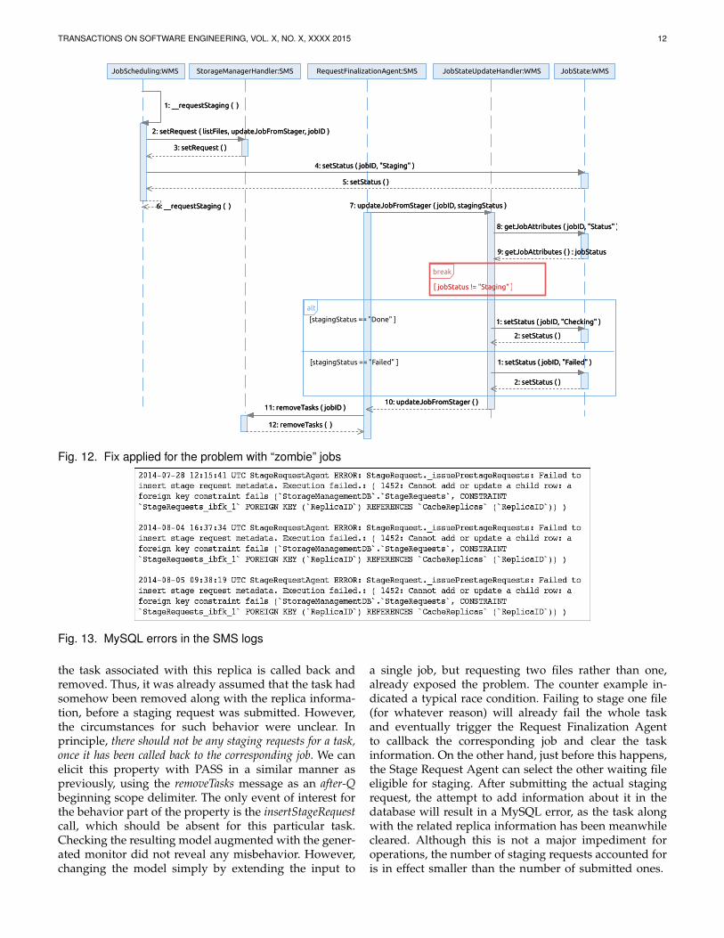
Model checking the property on the model augmentedwith the generated monitor revealed a counter-exampletrace where it does not hold. To understand why, thesequence diagram in Fig. 12 shows the fix originallyapplied (the break fragment). Some communication de-tails are omitted and messages are enumerated for clar-ity. Partial temporal ordering between these messagesis assumed, as imposed by the UML semantics. Thisimplies that in practice the sequence of events involv-ing the RequestFinalizationAgent (beginning with mes-sage 7:updateJobFromStager) can happen before 4:setJob-Status(jobID,“Staging”) takes place. In particular, whenthe staging request is processed very quickly by the SMS(e.g., if all files are already cached when the requestarrives), the callback from the agent may arrive beforethe job is set to a “Staging” state, and as a consequence,will be ignored because of the applied fix. Such unfor-tunate jobs will remain in a “Staging” state forever, dueto the fact that the request had been processed from theviewpoint of the SMS.
Another issue with the SMS was the occasionalMySQL error present in the logs, caused by a foreign keyconstraint violation (excerpts shown in Fig. 13). Usingknowledge about the database organization, the onlyway for this foreign constraint violation to manifest isif information referenced by the StageRequests entrywas removed from the CacheReplicas table prior tosubmitting a staging request. This, in turn, happens after
TRANSACTIONS ON SOFTWARE ENGINEERING, VOL. X, NO. X, XXXX 2015 11
Fig. 9. Eliciting the scope for a property with PASS
Fig. 10. Eliciting the behavior for a property with PASS
TRANSACTIONS ON SOFTWARE ENGINEERING, VOL. X, NO. X, XXXX 2015 12
JobStateUpdateHandler:WMSRequestFinalizationAgent:SMS JobState:WMSStorageManagerHandler:SMSJobScheduling:WMS
alt
[stagingStatus == "Done" ]
[stagingStatus == "Failed" ]
break
[ jobStatus != "Staging" ]
2: setStatus ( )
2: setStatus ( )
8: getJobAttributes ( jobID, "Status" )
4: setStatus ( jobID, "Staging" )
10: updateJobFromStager ( )
2: setRequest ( listFiles, updateJobFromStager, jobID )
5: setStatus ( )
1: setStatus ( jobID, "Checking" )
7: updateJobFromStager ( jobID, stagingStatus )
1: __requestStaging ( )
6: __requestStaging ( )
9: getJobAttributes ( ) : jobStatus
3: setRequest ( )
1: setStatus ( jobID, "Failed" )
1: __requestStaging ( )
6: __requestStaging ( )
2: setRequest ( listFiles, updateJobFromStager, jobID )
3: setRequest ( )
4: setStatus ( jobID, "Staging" )
5: setStatus ( )
7: updateJobFromStager ( jobID, stagingStatus )
10: updateJobFromStager ( )
8: getJobAttributes ( jobID, "Status" )
9: getJobAttributes ( ) : jobStatus
1: setStatus ( jobID, "Checking" )
2: setStatus ( )
1: setStatus ( jobID, "Failed" )
2: setStatus ( )
11: removeTasks ( jobID )11: removeTasks ( jobID )
12: removeTasks ( )12: removeTasks ( )
Fig. 12. Fix applied for the problem with “zombie” jobs
Fig. 13. MySQL errors in the SMS logs
the task associated with this replica is called back andremoved. Thus, it was already assumed that the task hadsomehow been removed along with the replica informa-tion, before a staging request was submitted. However,the circumstances for such behavior were unclear. Inprinciple, there should not be any staging requests for a task,once it has been called back to the corresponding job. We canelicit this property with PASS in a similar manner aspreviously, using the removeTasks message as an after-Qbeginning scope delimiter. The only event of interest forthe behavior part of the property is the insertStageRequestcall, which should be absent for this particular task.Checking the resulting model augmented with the gener-ated monitor did not reveal any misbehavior. However,changing the model simply by extending the input to
a single job, but requesting two files rather than one,already exposed the problem. The counter example in-dicated a typical race condition. Failing to stage one file(for whatever reason) will already fail the whole taskand eventually trigger the Request Finalization Agentto callback the corresponding job and clear the taskinformation. On the other hand, just before this happens,the Stage Request Agent can select the other waiting fileeligible for staging. After submitting the actual stagingrequest, the attempt to add information about it in thedatabase will result in a MySQL error, as the task alongwith the related replica information has been meanwhilecleared. Although this is not a major impediment foroperations, the number of staging requests accounted foris in effect smaller than the number of submitted ones.

TRANSACTIONS ON SOFTWARE ENGINEERING, VOL. X, NO. X, XXXX 2015 13
6 PROPERTY SPECIFICATIONS WITH µ-CALCULUS: A SURVEY OF PUBLISHED WORKS
We examined 25 published works2 that use the event-based µ-calculus as a target formalism to express systemproperties from various domains. Most of them weretaken from the CADP and mCRL2 case studies archives,both available online. Our main objective was to reassessthe usefulness of the PSP classification in the contextof µ-calculus and event-based systems, by fitting eachproperty in a specific pattern. In absence of the originalmodels for many of the publications, the “patterning”was done manually, consulting only the informationavailable in them. After identifying the pattern thatshould be applied, the formula was compared with theoriginal one used for the property. A secondary objectivewas to get an indication of how error-prone the manualformalization of properties can be in practice, even whenexperienced users are involved. Verifying the propertieson the actual models was beyond the scope of this work.
6.1 Is the PSP Classification Useful?Not all requirements could be fit in the classification. Weclassify a requirement as “patternizable” if its semanticscan be captured by some pattern from our extendedpattern classification. The majority of requirements couldbe fit into exactly one pattern. However, for some re-quirements, a conjunction of two patterns was necessaryto capture the semantics of the original requirementdescription. In such cases, individually checking thatthey all hold is equivalent to using the standard logicalconnective and (∧) to obtain a larger formula. We stillconsider such requirements as patternizable. Further-more, in some cases it was necessary to reformulate thegiven requirement description (without loss of meaning)in a way that captures the same semantics, but makesthe pattern-fitting more obvious. Consider the followingproperty from [34]:
After the input of a product and a rotation of the table, themain controller cannot command a drilling before the clamphas been blocked.At first glance, classifying it as an absence behavior (“can-not command a drilling”) with a between-Q-and-R scopewill not capture the precise semantics, because the be-ginning scope delimiter has only one placeholder, whilethe requirement has two (“After the input of a product anda rotation of the table”). With a slight reformulation:
After the input of a product and a rotation of the table, theclamp must be blocked before the main controller can commanda drilling.This is in fact a response chain behavior pattern with abefore-R scope. Indeed, the formula used in [34] corre-sponds to this exact pattern.
The results from the survey are shown in Table 2.From a total of 178 property descriptions encounteredin the publications, around 70% could be fitted within
2. The list of publications is available at http://remenska.github.io
the standard PSP classification. If our extensions aretaken into account, the coverage is improved by 10%.Among the 142 patternizable properties, there were 15for which a conjunction of two patterns was necessary.The properties that could not be captured by any pat-terns were usually such that a disjunction (set) of eventsmust be considered instead of a single event, within apattern. This is a current technical limitation of PASS,and enhancing the patterns in this direction is consideredas part of a future work.
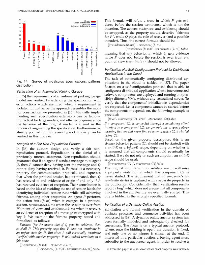
The distribution of the patterns is shown in Fig. 14. Animmediate observation, consistent with surveys focusingon state-based systems, is that a rather small number ofpatterns are sufficient to express the majority of require-ments. In fact, about 50% of the properties can be ex-pressed with two patterns: absence and precedence, whichindicates that safety properties are the most common, ifthe focus is not on a particular domain. Evidently, themost useful extensions are with respect to the fairness as-sumptions (both for existence and response), encounteredin 10 properties. It may be interesting to note that out ofthe 5 response chain properties, 4 were present in a singlepublication. The chain patterns are typically reported asthe least used, due to their complexity. The universalitypattern was never used, which is coherent with our ob-servation that this pattern is not really practical in event-based systems. However, we found that the alternativewe provided (always-enabled) was used once. The resultsalso indicate that the global scope is favored, comprisingabout 50% of the used scopes. We suspect that this ismostly due to the fact that safety properties typicallymust hold throughout the entire system execution. Onlytwo of our scope extensions, until-R and after-last-Q, werecaptured in 4 publications or 6 properties in total.
6.2 Is Manual Formalization of Properties Error-Prone?
We encountered several publications with wrong (orsuboptimal) property formalizations, where “wrong”means “not conveying the intention of the written nat-ural language requirement”. In the following we focuson these publications, discuss each problematic formulain more depth, and provide the correct one. Where nec-essary, we copy verbatim the informal requirement de-scription, to avoid misinterpretation. We want to clearlystate, however, that we intend no criticism on the pub-lication authors. These findings should only serve as anindication that writing correct formulas is a demandingtask, and should be supported by some guidance, toavoid errors.
TABLE 2Survey results: property specifications with µ-calculus
Patternizable?
No Yes (PSP) Yes (Extensions) Total
36 (≈ 20%) 126 (≈ 70%) 142 (≈ 80%) 178
TRANSACTIONS ON SOFTWARE ENGINEERING, VOL. X, NO. X, XXXX 2015 14
0
10
20
30
40
50
60
70
80
Glo
bally
Afte
r-Q
Afte
r-Q-U
ntil-R
Betw
een-Q
-and-R
Befo
re-R
Until-R
Afte
r-Last-Q
Absence
Pre
cedence
Response
Exis
tence
Bounded E
xis
tence
Exis
tence U
nder F
airn
ess
Response C
hain
1
Response U
nder F
airn
ess
Alw
ays-E
nable
d
Scope70
2018
1513
5
1
39
34
26
21
6 6 5 41
Scope ExtensionsBehavior
Behavior Extensions
Fig. 14. Survey of µ-calculus specifications: patternsdistribution
Verification of an Automated Parking GarageIn [35] the requirements of an automated parking garagemodel are verified by extending the specification witherror actions which are fired when a requirement isviolated. In that sense the approach resembles the mon-itor construction we presented in [16]. Manually imple-menting such specification extensions can be tedious,impractical for large models, and often error-prone, sincethe behavior of the original model is altered in theprocess of augmenting the specification. Furthermore, asalready pointed out, not every type of property can beverified in this manner.
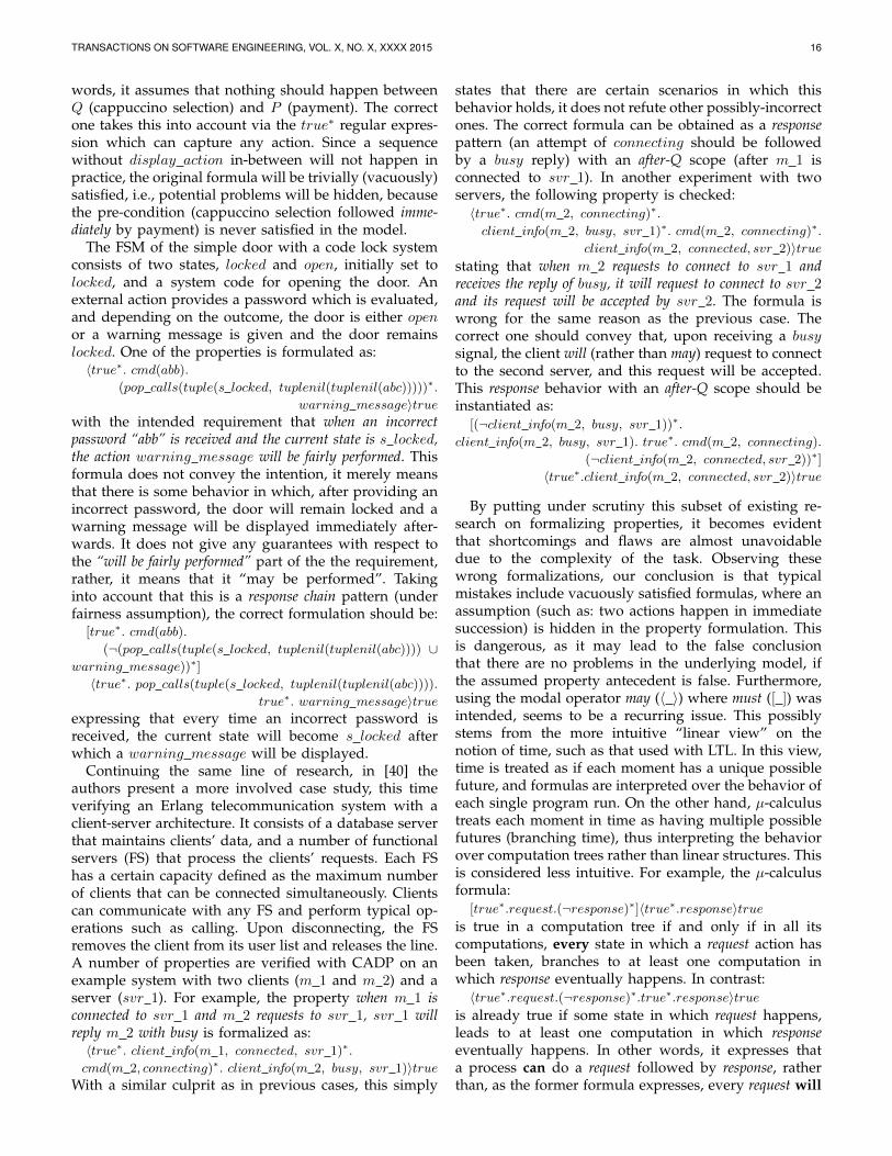
Analysis of a Fair Non-Repudiation ProtocolIn [36] the authors design and verify a fair non-repudiation protocol. Repudiation is the denial of apreviously uttered statement. Non-repudiation shouldguarantee that if an agent P sends a message m to agentQ, then P cannot deny having sent the message and Qcannot deny having received it. Fairness is a necessaryproperty for communication protocols, and expressesthat when the protocol session has terminated, then Qhas received m and evidence of origin if and only if Phas received evidence of reception. Their contribution isbased on the idea of avoiding the use of session labels foridentifying individual session runs while still achievingfairness, among other properties. An agent P performsthe action initP (k,m) when it engages in a protocolsession, terminateP (k,m) when the session is over fromP ’s point of view, and evidenceP (k,m) when it receivesan evidence of reception of a message m encrypted withkey k. We examine the fairness property, stated andformalized as follows:
Fairness (for P ) means that if Q gets its evidence, thenso shall P . This property says that P does not terminate inan unfair state for P . But since P will eventually terminate(verified with another property), P will indeed terminate in afair state.
[(¬evidenceQ(k,m))∗. evidenceP (k,m).
(¬evidenceQ(k,m))∗. terminateP (k,m)]false
This formula will refute a trace in which P gets evi-dence before the session terminates, which is not theintention. The actions evidenceP and evidenceQ shouldbe swapped, as the property should describe “fairnessfor P”, while Q plays the role of receiver (and a possibleintruder). Thus, the correct formula should be:
[(¬evidenceP (k,m))∗. evidenceQ(k,m).
(¬evidenceP (k,m))∗. terminateP (k,m)]false
meaning that any behavior in which Q gets evidencewhile P does not, before the session is over from P ’spoint of view (terminateP ), should not be allowed.
Verification of a Self-Configuration Protocol for DistributedApplications in the CloudThe task of automatically configuring distributed ap-plications in the cloud is tackled in [37]. The paperfocuses on a self-configuration protocol that is able toconfigure a distributed application whose interconnectedsoftware components are deployed and running on (pos-sibly) different VMs, without any centralized server. Toverify that the components’ initialization dependenciesare respected, i.e., a component cannot be started beforethe components it depends on, the following example isprovided:
[true∗. startcomp C1. true∗. startcomp C2]false
If a component C1 is connected through a mandatory clientinterface to a component C2, we generate the property abovemeaning that we will never find a sequence where C1 is startedbefore C2.Based on the given property description, this is anabsence behavior pattern (C1 should not be started) witha until-R or a before-R scope, depending on whether itis assumed that all components should eventually bestarted. If we do not rely on such assumption, an until-Rscope should be used:
[(¬startcomp C2)∗. startcomp C1]false
The original formula will not refute a run (it will missa property violation) in which the component C2 isnever started. The requirement that all components areeventually started is captured with a separate property inthe publication. Coincidentally, their verification resultsreport a bug3 which does not ensure that all componentsinvolved in the architecture are eventually started. Thisbug is hidden in the wrongly specified formula.
Verification of a Dynamic Online AuctionSimulation and formal verification in the domain ofbusiness processes and commerce activities has beenaddressed in [38]. A dynamic online auction system hasbeen formally modeled and subsequently checked forcorrectness. The focus is on a typical auction protocol,where, once the bidding is open, the duration is fixed,and only one or no winner is chosen at the end. Ifinterested in a particular auction, a buying agent mustsubscribe to the auctioneer agent, in order to receive a
3. From the paper, it is not clear which exact property was violated.
TRANSACTIONS ON SOFTWARE ENGINEERING, VOL. X, NO. X, XXXX 2015 15
call for proposal. The protocol is modeled with a singleauction, and a sale of one item by one seller to n buyerswho submit their bids to the auctioneer. A buying agentcan request to be removed from the auction by cancelingthe subscription. In the following, we list the incorrectlyspecified properties, and provide the correct ones.The auctioneer can not accept a subscription after the auctionends. This property is formalized as:
〈true∗. auctionFailure ∪ auctionSuccess.
true∗. acceptSubscribe〉true
The formula seems to capture exactly the opposite,namely, that an auction failure or auction success caneventually be followed by an agent subscription. Evenif we assume that this is an unintentional error, and thewhole formula was intended as a negation, i.e., specifiedas:
¬(〈true∗. auctionFailure ∪ auctionSuccess.
true∗. acceptSubscribe〉true)it is formalized in a sub-optimal way for model checking.The correct specification is a conjunction of two absencepatterns with an after-Q scope:
[(¬auctionFailure)∗. auctionFailure.true∗.acceptSubscribe]false
and[(¬auctionSuccess)∗. auctionSuccess.
true∗. acceptSubscribe]false
which should both hold individually. A very similarobservation can be made about the following property:An unsubscribed buyer can not receive a call for proposal.This property is expressed as:
¬(〈true∗. acceptCancelSub buyer.true∗. callForProposal buyer〉true)
Moreover, it is stated that the auction specification sup-ports the subscription and unsubscription of a buyer atany time during the auction. It is not clear whether thiscan be done multiple times, but if this is the case, theformula above will also mistakenly refute a behaviorwhere after cancellation, a buyer decides to subscribeagain. The property hereunder should formalize therequirement that after a subscription, a buyer can receivea call for proposal:
〈true∗. subscribe buyer. true∗. callForProposal buyer〉trueInstead, the formula specifies that there exists a certainrunning scenario in which a subscribed buyer will re-ceive a call for proposal. It does not guarantee that asubscribed buyer will eventually receive a call for pro-posal. Besides, the formula will falsely accept a scenariowhere a subscribed buyer decides to unsubscribe andthen receives a call for proposal, as a valid one. Basedon this brief description from the paper, it is ratherdifficult to elicit the correct property behavior withoutadditional information on the meaning of “can receivea call for proposal”. If the intent is that a subscribedbuyer should be able to receive a call for proposal at anypoint after subscription, then the correct formula (always-enabled behavior, after-Q scope) should be:
[(¬subscribe buyer)∗. subscribe buyer. true∗]〈callForProposal buyer〉true
If instead, the intent is that a subscribed buyer shouldeventually be able to receive a call for proposal, then theproperty (existence under fairness behavior, after-Q scope)is slightly more relaxed:
[(¬subscribe buyer)∗. subscribe buyer.(¬callForProposal buyer)∗]
〈true∗. callForProposal buyer〉true
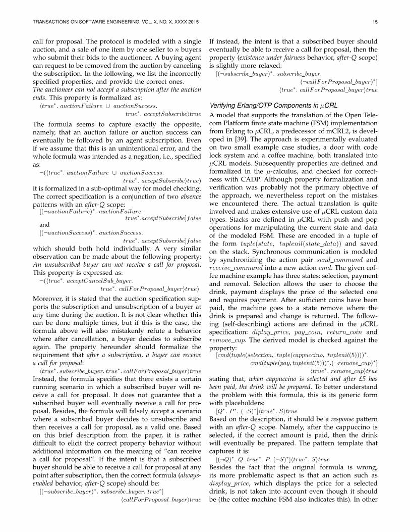
Verifying Erlang/OTP Components in µCRLA model that supports the translation of the Open Tele-com Platform finite state machine (FSM) implementationfrom Erlang to µCRL, a predecessor of mCRL2, is devel-oped in [39]. The approach is experimentally evaluatedon two small example case studies, a door with codelock system and a coffee machine, both translated intoµCRL models. Subsequently properties are defined andformalized in the µ-calculus, and checked for correct-ness with CADP. Although property formalization andverification was probably not the primary objective ofthe approach, we nevertheless report on the mistakeswe encountered there. The actual translation is quiteinvolved and makes extensive use of µCRL custom datatypes. Stacks are defined in µCRL with push and popoperations for manipulating the current state and dataof the modeled FSM. These are encoded in a tuple ofthe form tuple(state, tuplenil(state data)) and savedon the stack. Synchronous communication is modeledby synchronizing the action pair send command andreceive command into a new action cmd. The given cof-fee machine example has three states: selection, paymentand removal. Selection allows the user to choose thedrink, payment displays the price of the selected oneand requires payment. After sufficient coins have beenpaid, the machine goes to a state remove where thedrink is prepared and change is returned. The follow-ing (self-describing) actions are defined in the µCRLspecification: diplay price, pay coin, return coin andremove cup. The derived model is checked against theproperty:
[cmd(tuple(selection, tuple(cappuccino, tuplenil(5))))∗.
cmd(tuple(pay, tuplenil(5)))∗.(¬remove cup)∗]〈true∗. remove cup〉true
stating that, when cappuccino is selected and after £5 hasbeen paid, the drink will be prepared. To better understandthe problem with this formula, this is its generic formwith placeholders:
[Q∗. P ∗. (¬S)∗]〈true∗. S〉trueBased on the description, it should be a response patternwith an after-Q scope. Namely, after the cappuccino isselected, if the correct amount is paid, then the drinkwill eventually be prepared. The pattern template thatcaptures it is:
[(¬Q)∗. Q. true∗. P. (¬S)∗]〈true∗. S〉trueBesides the fact that the original formula is wrong,its more problematic aspect is that an action such asdisplay price, which displays the price for a selecteddrink, is not taken into account even though it shouldbe (the coffee machine FSM also indicates this). In other
TRANSACTIONS ON SOFTWARE ENGINEERING, VOL. X, NO. X, XXXX 2015 16
words, it assumes that nothing should happen betweenQ (cappuccino selection) and P (payment). The correctone takes this into account via the true∗ regular expres-sion which can capture any action. Since a sequencewithout display action in-between will not happen inpractice, the original formula will be trivially (vacuously)satisfied, i.e., potential problems will be hidden, becausethe pre-condition (cappuccino selection followed imme-diately by payment) is never satisfied in the model.
The FSM of the simple door with a code lock systemconsists of two states, locked and open, initially set tolocked, and a system code for opening the door. Anexternal action provides a password which is evaluated,and depending on the outcome, the door is either openor a warning message is given and the door remainslocked. One of the properties is formulated as:
〈true∗. cmd(abb).(pop calls(tuple(s locked, tuplenil(tuplenil(abc)))))∗.
warning message〉truewith the intended requirement that when an incorrectpassword “abb” is received and the current state is s locked,the action warning message will be fairly performed. Thisformula does not convey the intention, it merely meansthat there is some behavior in which, after providing anincorrect password, the door will remain locked and awarning message will be displayed immediately after-wards. It does not give any guarantees with respect tothe “will be fairly performed” part of the the requirement,rather, it means that it “may be performed”. Takinginto account that this is a response chain pattern (underfairness assumption), the correct formulation should be:
[true∗. cmd(abb).
(¬(pop calls(tuple(s locked, tuplenil(tuplenil(abc)))) ∪warning message))∗]
〈true∗. pop calls(tuple(s locked, tuplenil(tuplenil(abc)))).
true∗. warning message〉trueexpressing that every time an incorrect password isreceived, the current state will become s locked afterwhich a warning message will be displayed.
Continuing the same line of research, in [40] theauthors present a more involved case study, this timeverifying an Erlang telecommunication system with aclient-server architecture. It consists of a database serverthat maintains clients’ data, and a number of functionalservers (FS) that process the clients’ requests. Each FShas a certain capacity defined as the maximum numberof clients that can be connected simultaneously. Clientscan communicate with any FS and perform typical op-erations such as calling. Upon disconnecting, the FSremoves the client from its user list and releases the line.A number of properties are verified with CADP on anexample system with two clients (m 1 and m 2) and aserver (svr 1). For example, the property when m 1 isconnected to svr 1 and m 2 requests to svr 1, svr 1 willreply m 2 with busy is formalized as:
〈true∗. client info(m 1, connected, svr 1)∗.
cmd(m 2, connecting)∗. client info(m 2, busy, svr 1)〉trueWith a similar culprit as in previous cases, this simply
states that there are certain scenarios in which thisbehavior holds, it does not refute other possibly-incorrectones. The correct formula can be obtained as a responsepattern (an attempt of connecting should be followedby a busy reply) with an after-Q scope (after m 1 isconnected to svr 1). In another experiment with twoservers, the following property is checked:
〈true∗. cmd(m 2, connecting)∗.
client info(m 2, busy, svr 1)∗. cmd(m 2, connecting)∗.
client info(m 2, connected, svr 2)〉truestating that when m 2 requests to connect to svr 1 andreceives the reply of busy, it will request to connect to svr 2and its request will be accepted by svr 2. The formula iswrong for the same reason as the previous case. Thecorrect one should convey that, upon receiving a busysignal, the client will (rather than may) request to connectto the second server, and this request will be accepted.This response behavior with an after-Q scope should beinstantiated as:
[(¬client info(m 2, busy, svr 1))∗.
client info(m 2, busy, svr 1). true∗. cmd(m 2, connecting).
(¬client info(m 2, connected, svr 2))∗]
〈true∗.client info(m 2, connected, svr 2)〉true
By putting under scrutiny this subset of existing re-search on formalizing properties, it becomes evidentthat shortcomings and flaws are almost unavoidabledue to the complexity of the task. Observing thesewrong formalizations, our conclusion is that typicalmistakes include vacuously satisfied formulas, where anassumption (such as: two actions happen in immediatesuccession) is hidden in the property formulation. Thisis dangerous, as it may lead to the false conclusionthat there are no problems in the underlying model, ifthe assumed property antecedent is false. Furthermore,using the modal operator may (〈 〉) where must ([ ]) wasintended, seems to be a recurring issue. This possiblystems from the more intuitive “linear view” on thenotion of time, such as that used with LTL. In this view,time is treated as if each moment has a unique possiblefuture, and formulas are interpreted over the behavior ofeach single program run. On the other hand, µ-calculustreats each moment in time as having multiple possiblefutures (branching time), thus interpreting the behaviorover computation trees rather than linear structures. Thisis considered less intuitive. For example, the µ-calculusformula:
[true∗.request.(¬response)∗]〈true∗.response〉trueis true in a computation tree if and only if in all itscomputations, every state in which a request action hasbeen taken, branches to at least one computation inwhich response eventually happens. In contrast:
〈true∗.request.(¬response)∗.true∗.response〉trueis already true if some state in which request happens,leads to at least one computation in which responseeventually happens. In other words, it expresses thata process can do a request followed by response, ratherthan, as the former formula expresses, every request will
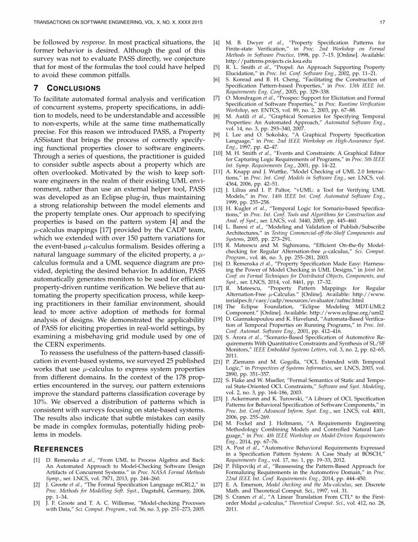
TRANSACTIONS ON SOFTWARE ENGINEERING, VOL. X, NO. X, XXXX 2015 17
be followed by response. In most practical situations, theformer behavior is desired. Although the goal of thissurvey was not to evaluate PASS directly, we conjecturethat for most of the formulas the tool could have helpedto avoid these common pitfalls.
7 CONCLUSIONS
To facilitate automated formal analysis and verificationof concurrent systems, property specifications, in addi-tion to models, need to be understandable and accessibleto non-experts, while at the same time mathematicallyprecise. For this reason we introduced PASS, a PropertyASSistant that brings the process of correctly specify-ing functional properties closer to software engineers.Through a series of questions, the practitioner is guidedto consider subtle aspects about a property which areoften overlooked. Motivated by the wish to keep soft-ware engineers in the realm of their existing UML envi-ronment, rather than use an external helper tool, PASSwas developed as an Eclipse plug-in, thus maintaininga strong relationship between the model elements andthe property template ones. Our approach to specifyingproperties is based on the pattern system [4] and theµ-calculus mappings [17] provided by the CADP team,which we extended with over 150 pattern variations forthe event-based µ-calculus formalism. Besides offering anatural language summary of the elicited property, a µ-calculus formula and a UML sequence diagram are pro-vided, depicting the desired behavior. In addition, PASSautomatically generates monitors to be used for efficientproperty-driven runtime verification. We believe that au-tomating the property specification process, while keep-ing practitioners in their familiar environment, shouldlead to more active adoption of methods for formalanalysis of designs. We demonstrated the applicabilityof PASS for eliciting properties in real-world settings, byexamining a misbehaving grid module used by one ofthe CERN experiments.
To reassess the usefulness of the pattern-based classifi-cation in event-based systems, we surveyed 25 publishedworks that use µ-calculus to express system propertiesfrom different domains. In the context of the 178 prop-erties encountered in the survey, our pattern extensionsimprove the standard patterns classification coverage by10%. We observed a distribution of patterns which isconsistent with surveys focusing on state-based systems.The results also indicate that subtle mistakes can easilybe made in complex formulas, potentially hiding prob-lems in models.
REFERENCES[1] D. Remenska et al., “From UML to Process Algebra and Back:
An Automated Approach to Model-Checking Software DesignArtifacts of Concurrent Systems.” in Proc. NASA Formal MethodsSymp., ser. LNCS, vol. 7871, 2013, pp. 244–260.
[2] J. Groote et al., “The Formal Specification Language mCRL2,” inProc. Methods for Modelling Soft. Syst., Dagstuhl, Germany, 2006,pp. 1–34.
[3] J. F. Groote and T. A. C. Willemse, “Model-checking Processeswith Data,” Sci. Comput. Program., vol. 56, no. 3, pp. 251–273, 2005.
[4] M. B. Dwyer et al., “Property Specification Patterns forFinite-state Verification,” in Proc. 2nd Workshop on FormalMethods in Software Practice, 1998, pp. 7–15. [Online]. Available:http://patterns.projects.cis.ksu.edu
[5] R. L. Smith et al., “Propel: An Approach Supporting PropertyElucidation,” in Proc. Int. Conf. Software Eng., 2002, pp. 11–21.
[6] S. Konrad and B. H. Cheng, “Facilitating the Construction ofSpecification Pattern-based Properties,” in Proc. 13th IEEE Int.Requirements Eng. Conf., 2005, pp. 329–338.
[7] O. Mondragon et al., “Prospec: Support for Elicitation and FormalSpecification of Software Properties,” in Proc. Runtime VerificationWorkshop, ser. ENTCS, vol. 89, no. 2, 2003, pp. 67–88.
[8] M. Autili et al., “Graphical Scenarios for Specifying TemporalProperties: An Automated Approach,” Automated Software Eng.,vol. 14, no. 3, pp. 293–340, 2007.
[9] I. Lee and O. Sokolsky, “A Graphical Property SpecificationLanguage,” in Proc. 2nd IEEE Workshop on High-Assurance Syst.Eng., 1997, pp. 42–47.
[10] M. H. Smith et al., “Events and Constraints: A Graphical Editorfor Capturing Logic Requirements of Programs,” in Proc. 5th IEEEInt. Symp. Requirements Eng., 2001, pp. 14–22.
[11] A. Knapp and J. Wuttke, “Model Checking of UML 2.0 Interac-tions,” in Proc. Int. Conf. Models in Software Eng., ser. LNCS, vol.4364, 2006, pp. 42–51.
[12] J. Lilius and I. P. Paltor, “vUML: a Tool for Verifying UMLModels,” in Proc. 14th IEEE Int. Conf. Automated Software Eng.,1999, pp. 255–258.
[13] H. Kugler et al., “Temporal Logic for Scenario-based Specifica-tions,” in Proc. Int. Conf. Tools and Algorithms for Construction andAnal. of Syst., ser. LNCS, vol. 3440, 2005, pp. 445–460.
[14] L. Baresi et al., “Modeling and Validation of Publish/SubscribeArchitectures,” in Testing Commercial-off-the-Shelf Components andSystems, 2005, pp. 273–291.
[15] R. Mateescu and M. Sighireanu, “Efficient On-the-fly Model-checking for Regular Alternation-free µ-calculus,” Sci. Comput.Program., vol. 46, no. 3, pp. 255–281, 2003.
[16] D. Remenska et al., “Property Specification Made Easy: Harness-ing the Power of Model Checking in UML Designs,” in Joint Int.Conf. on Formal Techniques for Distributed Objects, Components, andSyst., ser. LNCS, 2014, vol. 8461, pp. 17–32.
[17] R. Mateescu, “Property Pattern Mappings for RegularAlternation-Free µ-Calculus.” [Online]. Available: http://www.inrialpes.fr/vasy/cadp/resources/evaluator/rafmc.html
[18] The Eclipse Foundation, “Eclipse Modeling MDT-UML2Component.” [Online]. Available: http://www.eclipse.org/uml2
[19] D. Giannakopoulou and K. Havelund, “Automata-Based Verifica-tion of Temporal Properties on Running Programs,” in Proc. Int.Conf. Automat. Software Eng., 2001, pp. 412–416.
[20] S. Arora et al., “Scenario-Based Specification of Automotive Re-quirements With Quantitative Constraints and Synthesis of SL/SFMonitors,” IEEE Embedded Systems Letters, vol. 3, no. 2, pp. 62–65,2011.
[21] P. Ziemann and M. Gogolla, “OCL Extended with TemporalLogic,” in Perspectives of Systems Informatics, ser. LNCS, 2003, vol.2890, pp. 351–357.
[22] S. Flake and W. Mueller, “Formal Semantics of Static and Tempo-ral State-Oriented OCL Constraints,” Software and Syst. Modeling,vol. 2, no. 3, pp. 164–186, 2003.
[23] J. Ackermann and K. Turowski, “A Library of OCL SpecificationPatterns for Behavioral Specification of Software Components,” inProc. Int. Conf. Advanced Inform. Syst. Eng., ser. LNCS, vol. 4001,2006, pp. 255–269.
[24] M. Fockel and J. Holtmann, “A Requirements EngineeringMethodology Combining Models and Controlled Natural Lan-guage,” in Proc. 4th IEEE Workshop on Model-Driven RequirementsEng., 2014, pp. 67–76.
[25] A. Post et al., “Automotive Behavioral Requirements Expressedin a Specification Pattern System: A Case Study at BOSCH,”Requirements Eng., vol. 17, no. 1, pp. 19–33, 2012.
[26] P. Filipovikj et al., “Reassessing the Pattern-Based Approach forFormalizing Requirements in the Automotive Domain,” in Proc.22nd IEEE Int. Conf. Requirements Eng., 2014, pp. 444–450.
[27] E. A. Emerson, Model checking and the Mu-calculus, ser. DiscreteMath. and Theoretical Comput. Sci., 1997, vol. 31.
[28] S. Cranen et al., “A Linear Translation From CTL* to the First-order Modal µ-calculus,” Theoretical Comput. Sci., vol. 412, no. 28,2011.

TRANSACTIONS ON SOFTWARE ENGINEERING, VOL. X, NO. X, XXXX 2015 18
[29] S. Abrahao et al., “Assessing the Effectiveness of Sequence Dia-grams in the Comprehension of Functional Requirements: Resultsfrom a Family of Five Experiments,” IEEE Trans. Softw. Eng.,vol. 39, no. 3, pp. 327–342, 2013.
[30] OMG, “UML2.4 Superstructure Spec.” [Online]. Available: http://www.omg.org/spec/UML/2.4/Superstructure/Beta2/PDF
[31] D. Harel and S. Maoz, “Assert and Negate Revisited: Modal Se-mantics for UML Sequence Diagrams,” Software & Syst. Modeling,vol. 7, no. 2, pp. 237–252, 2008.
[32] A. Tsaregorodtsev et al., “DIRAC: A Community Grid Solution,”J. of Physics: Conf. Series, vol. 119, no. 6, 2008.
[33] D. Remenska, “Using Model Checking to Analyze the SystemBehavior of the LHC Production Grid,” 14th IEEE/ACM Int. Symp.Cluster, Cloud and Grid Computing, pp. 335–343, 2012.
[34] R. Mateescu, “Specification and Analysis of Asynchronous Sys-tems using CADP,” in Modeling and Verification of Real-Time Sys-tems - Formalisms and Software Tools, 2008.
[35] A. Mathijssen and A. J. Pretorius, “Specification, Analysis andVerification of an Automated Parking Garage,” Eindhoven Uni-versity of Technology, The Netherlands, Tech. Rep., 2005.
[36] J. Cederquist et al., “On the Quest for Impartiality: Design andAnalysis of a Fair Non-repudiation Protocol,” in Proc. Int. Conf.Inform. and Commun. Security, ser. LNCS, vol. 3783, 2005, pp. 27–39.
[37] G. Salaun et al., “Verification of a Self-configuration Protocol forDistributed Applications in the Cloud,” in Proc. 27th Annu. ACMSymp. on Applied Computing, ser. LNCS, vol. 7740, 2013, pp. 60–79.
[38] B. Chen and S. Sadaoui, “Simulation and Verification of a Dy-namic Online Auction,” in Proc. 7th Int. Conf. Software Eng. andApplications, 2003, pp. 385–390.
[39] Q. Guo, “Verifying Erlang/OTP Components in µCRL,” in Proc.Int. Conf. Formal Techniques for Networked and Distributed Syst., ser.LNCS, vol. 4574, 2007, pp. 227–246.
[40] Q. Guo et al., “Verifying Erlang Telecommunication Systems withthe Process Algebra µCRL,” in Proc. Int. Conf. Formal TechniquesNetworked and Distributed Syst., ser. LNCS, vol. 5048, 2008, pp.201–217.
Daniela Remenska received an Eng. degreein Computer Science from the Institute of In-formatics in Skopje, Macedonia. She moved tothe Netherlands in 2008 where she receiveda PDEng degree in Software Technology fromStan Ackermans’ School of Technological De-sign at TU/e in Eindhoven. Daniela is currently aPhD student at the HPDC group at VU UniversityAmsterdam, and is involved as grid Tier-1 rep-resentative for the CERN LHCb experiment atNIKHEF. Her research interests include analysis,
formal modeling of concurrent systems and high performance gridcomputing.
Kees Verstoep received a M.Sc. in ComputerScience from VU University, Amsterdam, in1990. His research interests include clusters,grids, clouds, model checking, and the perfor-mance analysis of large scale computer sys-tems. Kees Verstoep is currently a ScientificProgrammer in the Computer Systems group atVU University, in which role he also coordinatessystem management of the Distributed ASCISupercomputer (DAS-4).
Henri Bal is a full professor at the Faculty of Sci-ences of the Vrije Universiteit, where he headsthe High Performance Distributed Systems re-search group. He received a M.Sc. in mathe-matics from the Delft University of Technology in1982 and a Ph.D. in Computer Science from theVrije Universiteit in 1989. His research interestsinclude parallel and distributed programming,smart phones, and e-Science. He is the authorof more than 170 articles and (co-)author ofthree books. He is a Member of the Academia
Europeana and winner of the Euro-Par 2014 Achievement Award.
Tim Willemse received his PhD degree in com-puter science from the Eindhoven University ofTechnology 2003. He held positions at the Uni-versity of Nijmegen and the company ASML.Since 2006, he is an Assistant Professor at theDepartment of Computer Science, EindhovenUniversity of Technology, and, since 2010, he isaffiated with CERN (Switzerland). His researchinterests include concurrency theory, and verifi-cation and validation of concurrent and systems.
Jeff Templon is the leader of the Physics DataProcessing project at NIKHEF. He received hisPhD in experimental nuclear physics in 1993from Indiana University, and after postdoctoralstints at NIKHEF and MIT, was assistant pro-fessor of physics at the University of Georgia(Athens, USA) for several years, doing exper-iments at Jefferson Lab (USA) and MAMI inMainz. Jeff was almost always involved in com-puting for the various experiments in which heparticipated; he made it official in 2001 when
coming to NIKHEF to work on Grids. Since then he was worn manygrid ”hats”, starting during the European Data Grid project from beingthe sysadmin who installed grid site number 3, and one of the ”LooseCannons”, through work on the High Energy Physics Common Appli-cation Layer (HEPCAL) requirements documents, membership on theEGEE Technical Management Board, WLCG Management Board, andthe BiG Grid (Dutch National e-infrastructure) Executive Team. He is stilla part-time sysadmin to make sure he keeps his hands dirty.