
Formal Foundation for Pattern-Based Modelling
16
Formal Foundation for Pattern-Based Modelling Paolo Bottoni 1 , Esther Guerra 2 , and Juan de Lara 3 1 Universit` a di Roma “Sapienza” (Italy), [email protected] 2 Universidad Carlos III de Madrid (Spain), [email protected] 3 Universidad Aut´onoma de Madrid (Spain), [email protected] Abstract. We present a new visual and formal approach to the specifi- cation of patterns, supporting pattern analysis and pattern-based model completion. The approach is based on graphs, morphisms and opera- tions from category theory and exploits triple graphs to annotate model elements with pattern roles. Novel in our proposal is the possibility of describing (nested) variable submodels, as well as inter-pattern synchro- nization across several diagrams (e.g. class and sequence diagrams for UML design patterns). We illustrate the approach on UML design pat- terns, and discuss its generality and applicability on different types of patterns, e.g. workflow patterns using Coloured Petri nets. 1 Introduction Patterns are increasingly used in the definition of software frameworks, as well as in Model Driven Development, to indicate parts of required architectures, drive code refactorings, or build model-to-model transformations. The full realisation of their power is however hindered by the lack of a standard formalization of the notion of pattern. Presentations of patterns are typically given through natural language, to explain their motivation, context and consequences; programming code, to show usages of the pattern; and diagrams, to communicate their struc- ture and behavior. However, the use of domain modelling languages, such as UML for design patterns, or Coloured Petri Nets for workflows, forces pattern proposers to provide only examples of their realisation, appealing to intuition to extend them to the complete semantics of the pattern. For instance, the fact that in the Visitor pattern there must be a distinct operation in the Visitor interface for each ConcreteElement is only understood through generalisation of the examples or reading the associated text [4]. The search for a general definition of patterns, independent from the specific modelling language, has led to several proposals based on the association of con- straints to diagrammatic definitions, or to extensions of the UML meta-model, in order to distinguish roles from concrete modelling types. However, these pro- posals incur some problems to define the relations between different components of a patterns specification, as will be illustrated in Section 2. We propose a formal notion of pattern, grounded in category theory [9], which sees them as formed of: i) a vocabulary of roles; ii) a collection of dia- grams, possibly in different modelling languages, defining cardinalities and asso- ciations between roles, and supplemented with indications of variable regions; iii)
Transcript of Formal Foundation for Pattern-Based Modelling

Formal Foundation for Pattern-Based Modelling
Paolo Bottoni1, Esther Guerra2, and Juan de Lara3
1 Universita di Roma “Sapienza” (Italy), [email protected] Universidad Carlos III de Madrid (Spain), [email protected]
3 Universidad Autonoma de Madrid (Spain), [email protected]
Abstract. We present a new visual and formal approach to the specifi-cation of patterns, supporting pattern analysis and pattern-based modelcompletion. The approach is based on graphs, morphisms and opera-tions from category theory and exploits triple graphs to annotate modelelements with pattern roles. Novel in our proposal is the possibility ofdescribing (nested) variable submodels, as well as inter-pattern synchro-nization across several diagrams (e.g. class and sequence diagrams forUML design patterns). We illustrate the approach on UML design pat-terns, and discuss its generality and applicability on different types ofpatterns, e.g. workflow patterns using Coloured Petri nets.
1 Introduction
Patterns are increasingly used in the definition of software frameworks, as well asin Model Driven Development, to indicate parts of required architectures, drivecode refactorings, or build model-to-model transformations. The full realisationof their power is however hindered by the lack of a standard formalization of thenotion of pattern. Presentations of patterns are typically given through naturallanguage, to explain their motivation, context and consequences; programmingcode, to show usages of the pattern; and diagrams, to communicate their struc-ture and behavior. However, the use of domain modelling languages, such asUML for design patterns, or Coloured Petri Nets for workflows, forces patternproposers to provide only examples of their realisation, appealing to intuitionto extend them to the complete semantics of the pattern. For instance, the factthat in the Visitor pattern there must be a distinct operation in the Visitorinterface for each ConcreteElement is only understood through generalisationof the examples or reading the associated text [4].
The search for a general definition of patterns, independent from the specificmodelling language, has led to several proposals based on the association of con-straints to diagrammatic definitions, or to extensions of the UML meta-model,in order to distinguish roles from concrete modelling types. However, these pro-posals incur some problems to define the relations between different componentsof a patterns specification, as will be illustrated in Section 2.
We propose a formal notion of pattern, grounded in category theory [9],which sees them as formed of: i) a vocabulary of roles; ii) a collection of dia-grams, possibly in different modelling languages, defining cardinalities and asso-ciations between roles, and supplemented with indications of variable regions; iii)

a collection of interfaces between these diagrams, to identify roles across differ-ent diagrams. Two main results are thus obtained, representing a distinguishingnovel feature of the approach. First, dependencies among different componentsof a pattern specification can be formally defined. Second, a clear specification ofthe parts of the pattern which can be replicated (and of the admissible numberof replicas) is given, without recurring to concrete examples. As our notion ofpattern generalises patterns from different fields, it opens the way to the exten-sion of pattern-based techniques to new areas, to the formalisation of existingones, and in general, to the development of pattern-based languages.
The paper is organized as follows. Section 2 presents related approaches.Section 3 introduces our new definition of pattern. Section 4 shows the procedurefor pattern application. Finally, Section 5 ends with the conclusions.
2 Related Work
The shortcomings of presenting patterns in the GoF (Gang of Four [4]) style havebeen addressed by several researchers, who advocate a more formal approach.For example, [3] extends the UML meta-model for class diagrams with specificroles and constraints. Conformance of a model to a pattern is checked as theusual model/meta-model relationship. The technique works for UML class andsequence diagrams, and the emphasis is on specification of patterns, but noton their use for model completion. A non-uniform interpretation of interactiondiagrams is provided, where reference to interaction fragments is translated totheir unfolding with respect to the instantiation of roles.
The limitations posed by reference to UML diagrams, in particular as re-gards premature commitment to hierarchical structures, are overcome in [10]by extending the UML meta-model with stereotypes accounting for possible re-alizations of a given pattern. A distinction between roles, types and classes isused in [8] to decouple representations of roles, at which level the semantics ofthe pattern is abstractly described by incorporating constraint diagrams intothe UML notation, from their refinement as types, and their implementationinto classes. This way, the GoF presentation of patterns is shown to be a real-ization of the abstract level. However, commitment to names and multiplicitiesis already needed at the type level, with the class level providing concrete im-plementations. Our proposal, on the contrary, provides the separation throughtriple graphs which establish a correspondence between roles in a pattern modeland types in a pattern specification. Variability is thus maintained also at thetype level, leaving matching morphisms to provide the relation with any givenrealization of the pattern. Independence from UML is achieved in [7] by usingObject-Z, but it is limited to structural aspects. Constraints on the use of pat-terns are exploited in [14] to maintain the consistency of a pattern-based softwareframework through the use of high-level transformations specific to each pattern.
In [1] a method is proposed for visualizing the roles of the elements in UMLclass and communication diagrams. The technique extends the UML Profilemeta-model with stereotypes and tagged values for pattern annotation. This

also allows pattern composition through single instances. In [6] the intent ofdesign patterns is described with an ontology, which can be queried to obtainsuggestions about the most appropriate pattern solving a certain problem.
In [13], the authors propose a logic-based approach, using subsets of FirstOrder Logic – for structural aspects – and Temporal Logic of Actions – forbehavioral ones – and supporting pattern combinations. As the language doesnot include implications, support for complex constraints appears limited.
Graph transformation [2] has also been used to formalise patterns. In [11],patterns are represented with rules, applied to abstract syntax trees to anno-tate the pattern instances found. In [12], models are transformed to conform topatterns, after having exploited graph queries that detect needs for transforma-tions. In [16] Spatial Graph Grammars provide a graph representation of GoFpatterns, to transform object structure graphs so that they conform to patterns.Although declarative, the rules are based on a concrete presentation of patterns,and not on a meta-model characterisation.
In general, we observe the lack of an integrated, domain-independent formal-ism able to give account of mutual synchronization constraints within a patternand across different ones, and to support pattern checking, identification andapplication. In the rest of the paper we present such a formalism.
3 Pattern Specification
3.1 Variable Patterns
We define a variable pattern as made of a fixed part root and a number of vari-able parts Vi, which can be replicated according to a given interval (low, high).Variable patterns support nesting – variable parts inside variable parts – and canbe used with any graph model, from unattributed graphs G = (VG, EG, src, tgt :EG → VG), to typed node and edge attributed graphs (e.g. E-graphs [2]). Herewe use typed attributed graphs and injective morphisms.
Definition 1 (Variable Pattern). A variable pattern is defined as V P =(P = {Vi}i∈I , root ∈ P, int : P → N× (N∪ {∗}), Emb = {vi,j : Vi → Vj |∃Vi, Vj ∈P}), where Vi are non-empty graphs, vi,j are injective morphisms, Emb is a treewith graphs Vi ∈ P as nodes and morphisms vi,j as edges, rooted in root ∈ P ,and int is a function returning the variability interval for each graph Vi ∈ P .
A finite set S satisfies interval (l, h), written S C (l, h), iff |S| ≥ l andh = ∗∨ |S| ≤ h. Note that if (l, h) is such that l > h, then it cannot be satisfied.Example. The GoF Observer pattern captures one-to-many dependencies be-tween objects so that when the subject object changes its state, all the depen-dent observer objects are notified and updated automatically. Fig. 1 presents asimplified version of this pattern using Def. 1. The left part directly encodes thetheoretical form, with full definition V P = (P = {VOb, VConc}, root = VOb, int ={(VOb, (0, ∗)), (VConc, (1, ∗))}, Emb = {vOb,Conc}). The variability interval is re-lated to the satisfiability of the pattern by a model. VOb has (0, ∗) as variability

Ob,Conc
Subject Observer
ConcreteSubject
Subject Observer
ConcreteObserverConcreteSubject
V (0, *)Ob V (1, *)Conc
vSubject Observer
ConcreteSubject ConcreteObserver
(0, *)
(1, *)
Fig. 1. The Observer Pattern in Theoretical (left) and Compact (right) Forms.
interval, thus the pattern is not mandatory and we may have any number ofinstances. As int(VConc) = (1, ∗), we require at least one ConcreteObserver ineach pattern instance. The right part of the figure shows a compact form, wherefixed and variable parts are presented together. In the figure, we use the concretesyntax of UML class diagrams, but the abstract syntax can also be used. ¥
The next definition states when a given graph satisfies a variable pattern.
Definition 2 (Pattern Satisfaction). Given a graph G and a variable patternV P as in Def. 1, G satisfies V P , written G |= V P , iff:
– Mroot = {pkroot : root → G} C int(root).
– ∀vi,j : Vi → Vj ∈ Emb:• ∀pk
i ∈ Mi, Mkj = {pl
j : Vj → G|pki = pl
j ◦ vi,j} C int(Vj).• Define Mj =
⋃Mk
j , with k = 1..|Mi|.
root
j
VjV
i
vij
pmj
Vj
Vj
Vi
vij
vij
...
pnj
p1j
vij
vroot,i
vroot, i p
sj
pnip
1root
p1i
G
...
...
...
...
...
...
...V
GOb1
ConcreteObserverConcreteSubject
Subject ObserverVConc
ConcreteObserverConcreteSubject
Subject ObserverVConc
ConcreteSubject
Subject ObserverVOb
vOb,Conc
vOb,Conc
pConc1
pConc2
ObserverSubject
ClockTimer AnalogClockDigitalClock
p
Fig. 2. Pattern Satisfaction (left). Pattern Satisfaction Example (right).
Remark. The procedure in Def. 2 induces a tree traversal for Emb, becausewhen Vi → Vj is traversed, Mi must have been previously calculated. ¥
The left of Fig. 2 describes the morphisms for the satisfaction checking for avariable pattern with one level of nesting, i.e. Emb = {root → Vi, Vi → Vj}. Weassume one morphism p1
root ∈ Mroot. The procedure checks that the set M1i of all
morphisms p1i , ..., p
ni : Vi → G commuting with G
p1root← root
vroot,i→ Vi satisfies theinterval int(Vi) = (lowi, highi). Similarly, given each morphism pk
i ∈ Mi = M1i ,

each set Mkj of morphisms p1
j , ..., psj : Vj → G commuting with G
pki← Vi
vi,j→ Vj
satisfies the interval int(Vj). In the figure, we have replicated Vj and Vi for eachdifferent morphism pk
j and pki , to show more intuitively the tree traversal.
Example. The right of Fig. 2 shows a model G that satisfies the specification ofthe observer pattern of Fig. 1. The fixed part VOb occurs once, and the variable re-gion VConc twice. This is checked by building the set MConc = {p1
Conc : VConc →G, p2
Conc : VConc → G} C (1, ∗). In the figure, the dotted lines indicate some ofthe mappings induced by p1
Ob, p1Conc and p2
Conc. ¥
3.2 Annotating Structure with Roles: Triple Patterns
In order to specify a pattern, we need its structure (as given by a variablepattern), a vocabulary of pattern roles, and a mapping from the elements inthe pattern to the vocabulary. We call this structure annotated pattern andground it in the notion of triple graph [5], composed of two graphs, source andtarget, related through a correspondence graph. Nodes in the correspondencegraph (also called mappings) have morphisms to nodes or edges in the other twographs. Thus, mappings may relate two nodes, two edges, an edge and a node,or just point to a single element in the source or target graphs [5].
Definition 3 (Triple Graph). A triple graph TrG = (Gs, Gc, Gt, cs, ct) hasthree graphs Gi (i ∈ {s, c, t}), and two functions cj : VGc → VGj ∪ EGj ∪ {·}(j = s, t).
The element “·” in the codomain of cj denotes that the correspondence func-tion cj can be undefined. A triple graph is also written as (Gs
cs←− Gcct−→ Gt).
We say that a node or edge x of Gs is related to a node or edge y of Gt iff∃n ∈ VGc s.t. x
cs←−[ n ct7−→ y and we write x relTrG y. As [5] showed, triplegraphs and morphisms form the category4 TrGraph [9].Example. Fig. 3 shows a triple graph. Its source graph Gs at the bottom con-forms to the UML meta-model, its target Gt at the top is a pattern vocabularymodel, and the correspondence graph Gc maps UML elements to vocabularyelements. The morphisms from the nodes in Gc are shown as dotted arrows.The correspondence function cs is undefined for node :PatternInstance (i.e.cs(:PatternInstance) = ·) and this is represented by omitting the edge. ¥
Triple graphs are typed by meta-model triples [5] made of two meta-models,source and target, related through a correspondence meta-model. In our case, ameta-model triple relates the meta-model of a specific language (e.g. UML) withthat of a generic pattern vocabulary, which can be refined by subclassification inorder to define patterns for the language. The top of Fig. 4 shows the meta-modelfor the vocabulary. All classes except the subclasses of PatternRole allow defin-ing patterns in any language. A Pattern has a name and a type, contains par-ticipating roles, and can be documented with its motivation, applicability, intent
4 A category is made of objects (e.g, triple graphs) and arrows (e.g., triple morphisms)satisfying some conditions [9].

name=’rProxy’
:OperationRole
owned
UML Model
Corresp. Model
participantparticipantparticipantparticipantparticipant
participant
specific specific
ownedOperation
Operation
name=’Proxy’
:ClassRole
name=’realSubject’
:AssociationRole
:AssocMap
name=’Subject’
:ClassRole
:ClassMap:ClassMap
name=’SimpleProxy’type=’structural’
:Pattern
:OperMap
:OperationRole
name=’request’Vocabularyfor UML Proxy
Pattern
name=’RealSubject’
:ClassRole
name=’rReal’
:OperationRole
:Generalization:GeneralizationrealSubject:Class proxy:Class
isAbstract = true
subject:Classrequest:Operation
name = xisAbstract = true
request:Operation
name = x
request:Operation
name = x
ownedOperation
:Property:Property realSubject:Association
participant
:OperMap:ClassMap:OperMap
Instance:Pattern
Fig. 3. Annotated Pattern with the Structural Part of the Proxy (in Abstract Syntax).
and consequences. Relations between patterns are given through the Relationassociation class. We have specialized the meta-model for UML, so that roles areapplicable to operations, classifiers, classes, structural features and associations.The bottom of Fig. 4 partially shows the UML meta-model, and the correspon-dence meta-model maps roles to UML elements. The PatternInstance class isused to group the mappings of each pattern instantiation.
+ name: String
Pattern
+ type: String
StructuralFeatureRole
AssociationRoleOperationRole
+ name: String
PatternRole
ClassifierRole
ClassRole
RoleMap OperMap AssocMap StructMap ClassiMap ClassMap
ClassifierStructuralFeatureAssociationOperation Class
+ how: String
Motivation
+ why: String
Intent
+ rel: String
Relation
+ desc: String
Consequence
+ when: String
Applicability
InstancePattern
Pattern VocabularyMeta−Model (for UML)
*
UML Meta−Model
Meta−ModelCorrespondence
* **
1
*1
*participant
1..* 1..*11
Fig. 4. Meta-model Triple for UML Patterns.
A pattern-annotated model is a triple graph whose source is a model in somelanguage (e.g. UML), and the target contains a subgraph isomorphic to a patternvocabulary, for each pattern used in the source model. The correspondence graphis called annotation graph and has a PatternInstance node for each patterninstance and one RoleMap for each element playing a role in the instance. For

example, the annotated pattern in Fig. 3, specifying the structure of the Proxypattern [4], conforms to the meta-model triple in Fig. 4. The intent of this designpattern is to provide a surrogate or placeholder proxy for an object with rolerealSubject in order to control access to it. The bottom part of Fig. 3 uses theabstract syntax for UML class diagrams. For simplicity, we only show the patternand the roles in the vocabulary model. The pattern has only one fixed graph,no variable part, and requires that the operations in Subject, RealSubject andProxy have the same name, which is modelled with a variable x. More complexattribute conditions such as in [2] are possible. We have omitted the name ofclasses and associations, so they can be mapped to any name.
An annotated pattern is a variable pattern where all the graphs in Def. 1 aretriple graphs, and morphisms are triple morphisms. The notion of pattern satis-faction remains as in Def. 2, but using triple graphs. Thus, annotated patternsare satisfied by triple graphs, called pattern-annotated models.Example. Workflow patterns [15] collect recurring constructs from existingworkflow systems and provide descriptions of their usage. Their presentationis textual in the style of GoF patterns. For control flow patterns, dealing withsynchronization policies, an intuitive semantics is given through Coloured PetriNets showing example realizations of the pattern, to be inferred by the reader.Fig. 5 shows three annotated patterns expressed via a syntax identifying the roles
(2, *)
Multi−merge
(0, *)
AND−JoinGeneralized
(2, *)
(0, *)
Parallel Split
(0, *)
(2, *)
<<and>>
<<output>>
<<output>>
<<input>>
<<input>>
<<split>>
<<input>>
<<merging>>
<<output>>
Fig. 5. Workflow Patterns.
of places and transitions, as input, split, out-put, and, and merging. ¥
As seen before, a tool need not showthe triple graph to the user, but the anno-tation can be done by marking the sourcegraph [1]. However for the theory, an explicittriple graph has some advantages: (i) we donot modify or extend the source meta-model(e.g. the UML one) with additional classes orattributes for tagging; (ii) triple graphs helpin enforcing the patterns, as shown in Section 4; (iii) it is easier to distinguishthe instances of a pattern, as these are identified by PatternInstance nodes.
3.3 Synchronizing Different Variable Patterns
A pattern specification can be composed of more than one diagram. For instance,the GoF patterns are described using class and sequence diagrams. Thus, rela-tionships have to be established between the elements in the different diagrams,which we do through their roles in the pattern.Example. The Visitor pattern explicitly represents as objects the operations tobe performed on the elements of an object structure, so that new operations canbe defined without changing the classes of the elements on which they operate.It is one of the most complex GoF patterns as it requires two levels of variationfor the two hierarchies of Visitor (i.e. the operations) and Element (i.e. theobject structure), with the set of operations for Visitor varying together with

the ConcreteElement set. This covariance cannot be expressed through a con-straint on cardinalities, as it requires an exact match on types of parameters.The pattern is shown in Fig. 6, where the presence in the same variance region ofthe signatures for the visit operations constrains the types of their parametersto satisfy the constraint of equality with the types of ConcreteElement.
classclass class
(1, *) (1, *)
(0, *)behavioural diagram
visitConcreteElement(this)
accept(cv)
(0, *)
(1, *)
structural diagram
(1, *) cv:
<<ConcreteVisitor>>
ConcreteElement
+ accept (Visitor)
Element
<<accept>>
<<Element>>
<<accept>><<ConcreteElement>>
ConcreteElement
<<ObjectStructure>>
ConcreteVisitor<<ObjectStructure>>
ObjectStructureVisitor
<<ConcreteVisitor>>
ConcreteVisitor
<<Visitor>>
os:
<<visit>>
ce:
<<ConcreteElement>>
ObjectStructure
<<visit>>+ visitConcreteElement (ConcreteElement)
Fig. 6. Visitor Pattern.
Both the structural and the behavioral part of Visitor require two variableparts, relative to the two hierarchies. However, while in the structural part thetwo regions are independent, in the behavioral part they are nested. This re-flects the double constraint that each concrete visitor can be accepted by eachconcrete element and that each concrete visitor has an operation to visit eachconcrete element. The synchronization between the different regions involved isrepresented by the equality of the colours used in the different pattern graphs,and formally as a synchronization graph.
Fig. 7 shows the scheme of the two patterns for Visitor: SP : V SP1 ← V SP
0 →V SP
2 and IP : V IP0 → V IP
1 → V IP2 . SP has V SP
0 as root and two variable parts,
V IP0
vIP01 // V IP
1
vIP12 // V IP
2
I
iSP
²²
iIP
OO
e11// e22 ''I11
iSP11²²
iIP11
OO
I22
iSP22²²
iIP22
OO
V SP0
vSP01 //
vSP02
66V SP1 V SP
2
Fig. 7. Synchronization
and describes the structural part (a class diagram).IP has root V IP
0 and a variable part V IP1 with nested
V IP2 , modelling a sequence diagram. The synchroniza-
tion graph I11 ← I → I22 declares the intersections be-tween the roots and pairs of variable parts of each pat-tern. Morphism I → I11 is derived as we have V SP
0 →V SP
1 and V IP0 → V IP
1 , and similar for I → I22. Allsquares in the diagram must commute to ensure co-herence, so I → V SP
0 → V SP1 = I → I11 → V SP
1 , andsimilar for V IP
0 with I11 and I22. ¥Example. Fig. 8 shows a variation of the Proxy pat-tern, in concrete syntax, allowing several proxies fora given subject (V SP
0 → V SP1 ). The upper part (V IP
0 → V IP1 ) shows the an-
notated sequence diagram. For clarity, we show the classifiers of the p and rsobjects, as both classifiers play a role in the pattern. ¥
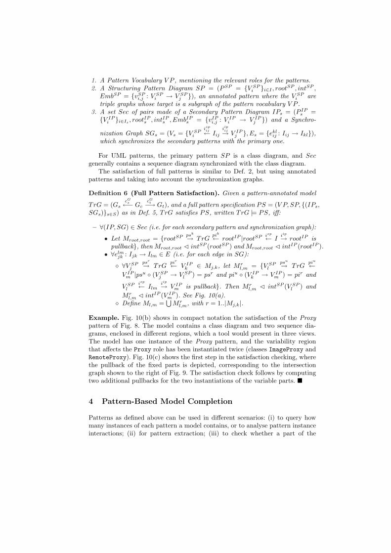
In Fig. 8 and others, we use a shortcut notation, shown below, for sequencediagrams. The OperMap node in the annotation graph points to the messagearrow for the invocation, while in the abstract syntax the morphism reaches theoperation to be executed through a MessageOccurrenceSpecification object.
RealSubject
rs:
class
n=’rProxy’
:OpRole
n=’Proxy’
:ClassRole
n=’RSubject’
:ClassRole
n=’rReal’
:OpRole
Proxy
+ request ()
RealSubject
+ request ()
Proxy
p:
n=’Proxy’
:ClassRole
n=’RSubject’
:ClassRole
RealSubject
rs:
n=’rProxy’
:OpRole
n=’rReal’
:OpRole
:Pattern
name=’Proxy’type=’structural’
n=’RSubject’
:ClassRole
RealSubject
:Pattern
name=’Proxy’type=’structural’
:Pattern
name=’Proxy’type=’structural’
name=’Proxy’type=’structural’
:Pattern V IP1V IP
0 I 11
:Pattern
name=’Proxy’type=’structural’
V SP1
n=’RSubject’
:ClassRole
n=’Subject’
:ClassRole
RealSubject
n=’rReal’
:OpRole
n=’request’
:OpRole
n=’Proxy’
:ClassRole
Proxy
+ request ()
n=’rProxy’
:OpRole
n=’rSubject’
:AssocRole
:Pattern
name=’Proxy’type=’structural’
V SP0
n=’RSubject’
:ClassRole
n=’Subject’
:ClassRole
n=’rReal’
:OpRole
n=’request’
:OpRole
RealSubject
n=’RSubject’
:ClassRole
class
request()
class
request()
I
+ request () + request ()
Subject
+ request () + request ()
Subject
:OperMap
:OperMap
:ClassMap
:ClassMap:ClassMap:OperMap :ClassMap :ClassMap :OperMap :AssocMap:OperMap:ClassMap:OperMap
:OperMap :OperMap:ClassMap :ClassMap :OperMap :ClassMap:ClassMap :ClassMap
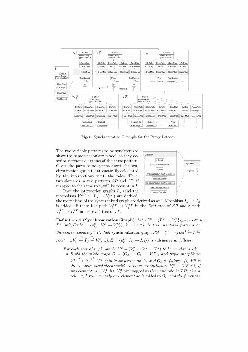
Fig. 8. Synchronization Example for the Proxy Pattern.
p:request()
:OperMap
:ConnectableElement
:ExecutionSpecification
:Lifeline
:MessageOccurrenceSpecification
:OperMap
request:Operation
:GeneralOrdering
p:Object
:ExecutionOccurrenceSpecification
The two variable patterns to be synchronizedshare the same vocabulary model, as they de-scribe different diagrams of the same pattern.Given the parts to be synchronized, the syn-chronization graph is automatically calculatedby the intersections w.r.t. the roles. Thus,two elements in two patterns SP and IP , ifmapped to the same role, will be present in I.
Once the intersection graphs Iij (and themorphisms V SP
i ← Iij → V IPj ) are derived,
the morphisms of the synchronized graph are derived as well. Morphism Iik → Ijl
is added, iff there is a path V SPi → V SP
j in the Emb tree of SP and a pathV IP
k → V IPl in the Emb tree of IP .
Definition 4 (Synchronization Graph). Let AP k = (P k = {V ki }i∈Ik , rootk ∈
P k, intk, Embk = {vki,j : V k
i → V kj }), k = {1, 2}, be two annotated patterns on
the same vocabulary V P ; their synchronization graph SG = (V = {root1 i1← Ii2→
root2, ..., V 1i
i1ij← Iij
i2ij→ V 2j , ...}, E = {ekl
ij : Iij → Ikl}) is calculated as follows:
– For each pair of triple graphs V k = (V ks ← V k
c → V kt ) to be synchronized:
• Build the triple graph O = (Os ← Oc → V P ), and triple morphisms
V 1 f1
−→ Of2
←− V 2, jointly surjective on Os and Oc as follows: (i) VP isthe common vocabulary model, so there are inclusions V k
t ↪→ V P (ii) iftwo elements a ∈ V 1
s , b ∈ V 2s are mapped to the same role in V P , (i.e. a
relV 1 x, b relV 2 x) only one element ab is added to Os, and the functions

f1 and f2 identify a and b to such element, f1(a) = ab = f2(b) (if abdoes not exist, the graphs cannot be synchronized).
• Intersection I is given by the pullback 5 V 1 i1← Ii2→ V 2 of V 1 f1
→ Of2
← V 2.– Given two intersection nodes V 1
r ← Irs → V 2s and V 1
u ← Iuv → V 2v s.t. there
are paths V 1u → V 1
r in Emb1 and V 2v → V 2
s in Emb2, add edge ersuv : Iuv →
Irs to SG, as morphism ersuv uniquely exists due to the pullback universal
property [2], see the left of Fig. 9.
Remark. Two graphs V 1 and V 2 can be synchronized only if their variabilityintervals overlap (i.e. ∃M |M C int1(V 1) and M C int2(V 2)).
:ClassRole
:ClassMap
RealSubjectrs:
n=’RSubject’
:ClassRole
:ClassMap
n=’RSubject’
:ClassRole
n=’Subject’
:ClassRole
:Pattern
name=’Proxy’type=’structural’
n=’rReal’
:OpRole
n=’request’
:OpRole
V SP0
n=’RSubject’
:ClassRole
n=’Subject’
:ClassRole
:Pattern
name=’Proxy’type=’structural’
n=’rReal’
:OpRole
n=’request’
:OpRole
n=’rProxy’
:OpRole
n=’Proxy’
:ClassRole
n=’rSubject’
:AssocRole
rs:
class
V IP0:Pattern
name=’Proxy’type=’structural’ type=’structural’
n=’RSubject’
RealSubject
+ request () + request ()
SubjectRealSubject
+ request () + request ()
SubjectRealSubject
OI :Pattern
name=’Proxy’
class
:ClassMap:ClassMap:OperMap :OperMap
:OperMap :ClassMap :OperMap:ClassMap
O
V 1r
f1
¨¨
CC¨
V 2s
f2777
[[777
V 1u
v1ur
OO
Irs
i1rs666
[[666i2rs©©©
CC©©©
P.B.
V 2v
v2vs
OO
Iuv
ersuv
OO
i1uv777
[[777i2uv¨
¨
CC¨
Fig. 9. Calculating Intersection Edges (left). Example (right).
Example. The right of Fig. 9 shows an example of the calculation of an inter-section graph for the synchronization scheme shown in Fig. 8. ¥
3.4 Full Pattern Specification
We now put all elements together to define a full pattern, made of a primarystructuring pattern SP , and a number of secondary patterns IPi synchronizedwith SP through synchronization graphs SGi.
Definition 5 (Full Pattern Specification). A Full Pattern Specification PS =(V P, SP, Sec = {(IPs, SGs)}s∈S) is composed of:5 Roughly, a pullback [9] is the biggest intersection of two objects Ai through a com-
mon one B to which both are mapped. The pullback A1 ← C → A2 identifies theelements of A1 and A2 that are mapped to a common element in B.
1. A Pattern Vocabulary V P , mentioning the relevant roles for the patterns.2. A Structuring Pattern Diagram SP = (PSP = {V SP
i }i∈I , rootSP , intSP ,
EmbSP = {vSPi,j : V SP
i → V SPj }), an annotated pattern where the V SP
i aretriple graphs whose target is a subgraph of the pattern vocabulary V P .
3. A set Sec of pairs made of a Secondary Pattern Diagram IPs = (P IPs =
{V IPi }i∈Is
, rootIPs , intIP
s , EmbIPs = {vIP
i,j : V IPi → V IP
j }) and a Synchro-
nization Graph SGs = (Vs = {V SPi
ispij← Iij
iipij→ V IP
j }, Es = {eklij : Iij → Ikl}),
which synchronizes the secondary patterns with the primary one.
For UML patterns, the primary pattern SP is a class diagram, and Secgenerally contains a sequence diagram synchronized with the class diagram.
The satisfaction of full patterns is similar to Def. 2, but using annotatedpatterns and taking into account the synchronization graphs.
Definition 6 (Full Pattern Satisfaction). Given a pattern-annotated model
TrG = (GscG
s←− GccG
t−→ Gt), and a full pattern specification PS = (V P, SP, {(IPs,SGs)}s∈S) as in Def. 5, TrG satisfies PS, written TrG |= PS, iff:
– ∀(IP, SG) ∈ Sec (i.e. for each secondary pattern and synchronization graph):
• Let Mroot,root = {rootSP psk
→ TrGpik
← rootIP |rootSP isp
← Iiip
→ rootIP ispullback}, then Mroot,root C intSP (rootSP ) and Mroot,root C intIP (rootIP ).
• ∀elmjk : Ijk → Ilm ∈ E (i.e. for each edge in SG):
¦ ∀V SPj
psr
→ TrGpir
← V IPk ∈ Mj,k, let Mr
l,m = {V SPl
psu
→ TrGpiu
←V IP
m |psu ◦ (V SPj → V SP
l ) = psr and piu ◦ (V IPk → V IP
m ) = pir and
V SPl
isp
← Ilmiip
→ V IPm is pullback}. Then Mr
l,m C intSP (V SPl ) and
Mrl,m C intIP (V IP
m ). See Fig. 10(a).¦ Define Ml,m =
⋃Mr
l,m, with r = 1..|Mj,k|.
Example. Fig. 10(b) shows in compact notation the satisfaction of the Proxypattern of Fig. 8. The model contains a class diagram and two sequence dia-grams, enclosed in different regions, which a tool would present in three views.The model has one instance of the Proxy pattern, and the variability regionthat affects the Proxy role has been instantiated twice (classes ImageProxy andRemoteProxy). Fig. 10(c) shows the first step in the satisfaction checking, wherethe pullback of the fixed parts is depicted, corresponding to the intersectiongraph shown to the right of Fig. 9. The satisfaction check follows by computingtwo additional pullbacks for the two instantiations of the variable parts. ¥
4 Pattern-Based Model Completion
Patterns as defined above can be used in different scenarios: (i) to query howmany instances of each pattern a model contains, or to analyse pattern instanceinteractions; (ii) for pattern extraction; (iii) to check whether a part of the

���������������������������������������������������������������������������������������������������������������������������������������������������������������������������������������������������������������������������������������������������������������������������������������������������������������������������������������������������������������������������������������
���������������������������������������������������������������������������������������������������������������������������������������������������������������������������������������������������������������������������������������������������������������������������������������������������������������������������������������������������������������������������������������
������������������������������������������������������������������������������������������������������������������������������������������������������������������������������������������������������������������������������������������������������������������������������������������������������������������������������������������������������������������������������������������������������
������������������������������������������������������������������������������������������������������������������������������������������������������������������������������������������������������������������������������������������������������������������������������������������������������������������������������������������������������������������������������������������������������
{(RealSubject,Image)}
rs:
V IP0
class
I
{(Subject,Graphic),(request,draw),(request,draw),(RealSubject,Image)}
class classclass
draw() draw()draw()draw()
(a)
(c)(b)
M
classclass
draw()draw() draw()
class
draw()
V SP0
p:
<<Subject>>
<<rProxy>>
+ draw ()
ImageProxy
<<rProxy>>
<<Proxy>>
RealSubject
+ draw ()<<rProxy>>
RemoteProxy<<Proxy>>
+ request ()
Subject
+ draw ()
Image
<<rReal>>
<<RSubject>>
<<request>>
<<Subject>>
<<RSubject>>
+ draw ()
+ request ()<<rReal>>
RealSubject<<RSubject>>
rs: p:
<<rReal>><<rProxy>> <<rProxy>>
+ draw ()<<rProxy>>
RemoteProxy<<Proxy>>
<<rReal>>
Graphic
+ draw ()
Image
<<rReal>>
<<RSubject>>
RealSubject<<RSubject>>
+ draw ()
ImageProxy
<<rProxy>>
<<Proxy>>
rs:
<<rReal>>
<<request>>
p:
<<rProxy>>
p:
+ draw () <<request>>
<<rReal>>
Graphic
<<Subject>>
Ilm
isplm
||
iiplm
""Ijk
elmjk
OO
ispjk
wwnnnnnn i
ipjk
''OOOOOO
P.B.V SPl
psu 00
V SPj
vSPjloo
psr ((PPPPP V IPk
vIPkm //
pirvvnnnnn V IPm
piunnTrG
Fig. 10. (a) Satisfaction of Full Pattern, where Outer Square is Pullback. (b) AnnotatedModel Satisfying the Proxy Pattern. (c) First Step in Satisfaction Checking.
model (maybe created by hand) conforms to a pattern; and (iv) to automaticallycomplete a model according to a pattern. In this section we concentrate on thelatter, giving the algorithm for pattern application for model completion andproving its correctness.
We start by showing how to apply the primary pattern, and then presenthow synchronization with the secondary patterns is achieved. Given a pattern(V P, SP, Sec = {(IPs, SGs)}s∈S), the application of the primary pattern SP toan annotated model M = (Ms ← Mc → Mt) is as follows:
1. Vocabulary Extension. Add the vocabulary of the pattern to Mt if it wasnot added before (i.e. this is the first instance of the pattern).
2. Role Annotation. The user selects in Ms the elements playing some rolein the pattern. Thus, a RoleMap node is created in Mc for each of theseelements, associated with a node pm of type PatternInstance. pm is a newnode for a new instance of the pattern, or an existing one, if extending aprevious instance. Construct the morphisms from the modified annotationgraph Mc to Mt and Ms. A new instance cannot be created if the numberof existing instances would exceed the interval for the pattern root.
3. Instance Extraction. Construct a pattern graph PG by navigating frompm to the elements in Mc belonging to the defined instance of the pattern,and from these to elements in Mt and Ms along the cs and ct morphisms.
4. Variability Instantiation. The user selects a number ri in the rangeint(Vi) = (li, hi) for each variable part Vi of the pattern, such that theexisting number of instances ei plus the new ones ri satisfy the interval.

Build a graph PC as the colimit6 of the fixed part of the pattern P andri + ei instantiations of each variable part.
5. Model Extension. Construct the pushout7 M ′ of PC and M through PG.
rootv1
wwoooo v1
''OOOO
V1v12 ££¥¥v12¿¿:
:... V1v12 ££¥¥
v12ÁÁ<
<
V2
..
... V2
ÃÃAA V2
~~}}... V2
ppPC // M ′
PG
OO//
P.O.
M
OO
Fig. 11. Application ofStructural Pattern.
Example. Fig. 11 shows the application of a pat-tern with variable part V1 and nested part V2.Once V1 and V2 are instantiated, we build the col-imit PC and the pushout M ′ of PC ← PG → M .
Fig. 12 shows the application of the Proxy to amodel M containing a class Image, which the usermapped to role RealSubject. The name of theoperation in the pattern (“request”, a variable) ismapped to the name of the operation in the model(“draw”), and similarly for class names. The userselected two instantiations of the variable part;hence two proxies are created in the resulting model M ′. In the pushout, thenew elements may contain variables, like the name of the Proxy class to be added.In this case, either the user provides a value (ImageProxy and RemoteProxy inthe example), or default ones are obtained from the role names. ¥
PC M’
MPG
V SP1V SP
1
V SP0
+ request ()
<<rReal>>
RealSubject<<RSubject>>
<<rReal>>
RealSubject
+ request ()
Subject
<<request>>
<<Subject>>
<<RSubject>>
<<request>>
+ request ()<<rProxy>>
Proxy<<Proxy>>
<<Subject>>
RealSubject
+ request ()<<rProxy>>
Proxy<<Proxy>>
<<RSubject>>
+ request ()
Subject
<<request>>
<<Subject>>
+ request ()<<rProxy>> + request ()<<rProxy>>
Proxy
+ draw () <<request>>
Subject<<Subject>>
<<Proxy>>
Proxy
+ draw ()
Image
<<rReal>>
<<RSubject>>
<<Proxy>>
+ request ()
+ draw () <<rProxy>>
<<Proxy>>
ImageProxy
<<rReal>>
RealSubject
+ draw () <<rProxy>>
<<Proxy>>
RemoteProxy
<<RSubject>>
<<request>>
<<Subject>>
+ request ()<<rReal>>
RealSubject<<RSubject>>
+ request ()
Subject
+ draw ()
Image
<<rReal>>
<<RSubject>>
+ request ()<<rReal>>
+ request ()
Subject
+ request ()
Fig. 12. Applying a Structural Pattern to an Annotated Model.
The application of the secondary patterns continues by enlarging the modelM ′ obtained in the previous procedure by a sequence of pushouts. Hence, we first
6 Roughly, a colimit [9] is the smallest object in which a diagram made of objects andmorphisms is embedded (assuming injective morphisms).
7 Given two objects Ai, whose “intersection” is given by A1 ← I → A2, the pushoutA1 → B ← A2 is their union, where the common elements (given by I) are “merged”.

check which variable parts V SPi were added to M to yield M ′ (steps 2a and 2b).
This is necessary as the user may have extended an existing instance. Then, thesynchronization graph is used to locate the variable part of the secondary patternV IP
l synchronized with V SPi , and a pushout is built. We use an intermediate
graph BIPkl (step 1) as pushout object, as it contains the intersection between
V IPl and the previous graph in the nesting structure, preventing the addition of
too many elements. The procedure is repeated for each secondary pattern:
1. ∀eiljk : Ijk → Iil, edge in the synchronization graph, calculate the pushout
object BIPkl as shown in Fig. 13(left). Morphism BIP
kl → V IPl exists due
to the pushout universal property. Note also that if there are morphismsV IP
k → M ′ and Iil → M ′, then we uniquely have BIPkl → M ′ due to the
pushout universal property. Graph BIPkl will be used later in this procedure.
2. For each (IP, SG) ∈ Sec do (i.e. for each sec. pattern and synch. graph):– Traverse the graphs used to build the colimit PC in step 4 of the previous
procedure (see Fig. 11) in depth first order.(a) Let V SP
i be the current node; calculate the pullback object X ofV SP
i → PC ← PG.(b) If X � V SP
i theni. If V SP
i = rootSP then update the model M ′ according to thepushout shown in the center of Fig. 13.
ii. Else let V SPj be the predecessor of V SP
i in EmbSP and updatethe model M ′ according to the diagram to the right of Fig. 13.
iii. Repeat• Let V IP
m be the child of V IPl in EmbIP . Update the model
(like in steps i and ii) for each instance V SPn s.t. V SP
n ← Inm →V IP
m , and whose pullback object X in V SPn → PC ← PG is
not isomorphic to V SPn .
Until all descendants of V IPl ∈ EmbIP have been visited.
Ijk//
²² P.O.
Iil
²²
¨¨
³³
V IPk
//
++
--
BIPkl
²²
¹¹
V IPl
M ′
Iij
ÄÄÄÄÄÄ
ÄÂÂ?
????
²²
V SPi
ÂÂ@@@
@@V IP
j
²²P.O.
M ′ // M ′′
Ijk
uukkkkkkkkkkkk
))SSSSSSSSSSSS
²²V SP
j
$$HHHH
,,
Iil
{{xxxxx
""FFFF
F P.O. V IPk
{{wwwww
²²V SP
i
##HHHH BIPkl
//
{{ P.O.
V IPl
²²M ′ // M ′′
Fig. 13. Building BIPkl (left). First (center) and Second (right) Cases for Model Update.
The procedure is incremental – one can update an existing instance – andsupports heterogeneous synchronization, e.g. Fig. 7, where the structural patternhas two independent variable parts and nesting in the interaction pattern.Example. For Proxy, Fig. 14 shows how the first sequence diagram is createdstarting from M ′ of Fig. 12. Note that, as there were two instantiations of V SP ,the procedure would follow by adding an additional sequence diagram. ¥

M’’’
V IP1
class
request()request()
classIrs:
class
V IP0 B IP
class
rs:
M’’
class
M’
rs:
class
class
draw()draw()
p:
<<request>>
Subject<<Subject>>
<<RSubject>>
ImageProxy
+ draw ()
Image
<<rReal>>
<<RSubject>>
<<Proxy>>
<<rProxy>>
+ draw () <<rProxy>>
<<Proxy>>
ImageProxy
<<rReal>>
RealSubject
+ draw () <<rProxy>>
<<Proxy>>
RemoteProxy
<<RSubject>>
Proxy<<Proxy>> <<RSubject>>
RealSubject
RemoteProxy
+ draw ()
rs:
+ draw () <<request>>
Subject<<Subject>>
<<rProxy>>+ draw ()
+ draw ()
Image
<<rReal>>
<<RSubject>>
+ draw () <<request>>
Subject<<Subject>>
<<rProxy>>
+ draw () <<rProxy>>
<<Proxy>>
ImageProxy
+ request ()
+ draw () <<rProxy>>
<<Proxy>>
RemoteProxy
<<rReal>>
RealSubject<<RSubject>>
<<Proxy>>
+ draw ()
Proxy<<Proxy>>
p:
<<rReal>>
+ request ()
<<rProxy>>
<<rProxy>>
Image
rs:
<<rReal>>
RealSubject<<RSubject>>
+ draw ()
Fig. 14. Synchronization: Building the First Sequence Diagram.
Finally, it can be shown that, after applying a pattern according to theprevious procedure, the resulting model satisfies such pattern according to Def. 6.
Proposition 1 (Application Correctness). If model Mk′ is obtained fromM by applying pattern SP according to the previous procedure, then Mk′ |= SP .
Proof Sketch. The nodes Iij of SG are the pullbacks of V SPi → O ← V IP
j . Whenapplying the primary pattern, the vocabulary model is added to M , and after thepushouts for the secondary pattern are made, yielding Mk′, we have O → Mk′.This implies that all Iij are the pullback objects of V SP
i → Mk′ ← V IPj . The
satisfaction Mk′ |= SP then follows as the application procedure takes care ofthe correctness of the replications w.r.t. the allowed variability intervals (step 4of the application of the primary pattern). ¥
5 Conclusions and Future Work
We have presented a formal approach to the specification of patterns, as wellas procedures for checking whether a model satisfies a pattern and applying apattern to a model for model completion. In the proposed formalization, patternsare annotated by roles in a vocabulary, support the synchronization of differenttypes of diagrams, and allow the definition of variable parts, possibly nested.The proposal relies on a general meta-model for patterns, not necessarily basedon UML.
Our approach presents several benefits w.r.t. existing ones. First, variabil-ity regions – with the possibility of nesting – are more flexible than currentproposals, which annotate single elements with cardinalities [3] and for whichit is more difficult to express that several elements have to vary together. Sec-ond, our mechanism for pattern application considers synchronization of severaldiagrams. Third, we separate the roles from the pattern structure by a triple
graph, without extending existing meta-models. This clean and non-intrusivesolution facilitates the manipulation and querying of the vocabulary models, aswell as the identification of pattern instances. Our formal treatment facilitatesthe derivation of rules for refactoring towards patterns.
We plan to investigate pattern conflicts and reason about pattern interactioneffects, e.g. using graph constraints or critical pairs [2] in pattern application.
Acknowledgments. Work supported by the Spanish Ministry of Scienceand Innovation, projects METEORIC (TIN 2008-02081) and MODUWEB (TIN2006-09678). We thank the referees for their insightful and detailed comments.
References
1. J. Dong, S. Yang, and K. Zhang. Visualizing design patterns in their applicationsand compositions. IEEE Trans. Software Eng., 33(7):433–453, 2007.
2. H. Ehrig, K. Ehrig, U. Prange, and G. Taentzer. Fundamentals of Algebraic GraphTransformation. Springer, 2006.
3. R. B. France, D.-K. Kim, S. Ghosh, and E. Song. A UML-based pattern specifi-cation technique. IEEE Trans. Software Eng., 30(3):193–206, 2004.
4. E. Gamma, R. Helm, R. Johnson, and J. M. Vlissides. Design Patterns. Elementsof Reusable Object-Oriented Software. Addison Wesley, 1994.
5. E. Guerra and J. de Lara. Event-driven grammars: Relating abstract and concretelevels of visual languages. Software and System Modeling, 6(3):317–347, 2007.
6. H. Kampffmeyer and S. Zschaler. Finding the pattern you need: The design patternintent ontology. In MoDELS, volume 4735 of LNCS, pages 211–225. Springer, 2007.
7. S. K. Kim and D. Carrington. Using integrated metamodeling to define OO designpatterns with Object-Z and UML. In APSEC, pages 257–264. IEEE ComputerSociety, 2004.
8. A. Lauder and S. Kent. Precise visual specification of design patterns. In ECOOP,volume 1445 of LNCS, pages 114–134, 1998.
9. S. Mac Lane. Categories for the Working Mathematician. 2nd Edition. GraduateTexts in Mathematics Vol 5. Springer, 1998.
10. J. K.-H. Mak, C. S.-T. Choy, and D. P.-K. Lun. Precise modeling of design patternsin UML. In ICSE, pages 252–261. IEEE Computer Society, 2004.
11. J. Niere, W. Schafer, J. P. Wadsack, L. Wendehals, and J. Welsh. Towards pattern-based design recovery. In ICSE, pages 338–348. ACM, 2002.
12. A. Radermacher. Support for design patterns through graph transformation tools.In AGTIVE, volume 1779 of LNCS, pages 111–126. Springer, 1999.
13. T. Taibi and D. C. L. Ngo. Formal specification of design pattern combinationusing BPSL. Information and Software Technology, 45:157–170, 2003.
14. T. Tourwe and T. Mens. High-level transformations to support framework-basedsoftware development. In SET, volume 72-4 of ENTCS, 2003.
15. W. van der Aalst, A. ter Hoefstede, B. Kiepuszewski, and A. Barros. Workflowpatterns. Distributed and Parallel Data Bases, 14(3):5–51, 2003.
16. C. Zhao, J. Kong, J. Dong, and K. Zhang. Pattern-based design evolution usinggraph transformation. J. Vis. Lang. Comput., 18(4):378–398, 2007.