FORM Manual English - Native Instruments
111
-
Upload
khangminh22 -
Category
Documents
-
view
2 -
download
0
Transcript of FORM Manual English - Native Instruments


The information in this document is subject to change without notice and does not represent acommitment on the part of Native Instruments GmbH. The software described by this docu-ment is subject to a License Agreement and may not be copied to other media. No part of thispublication may be copied, reproduced or otherwise transmitted or recorded, for any purpose,without prior written permission by Native Instruments GmbH, hereinafter referred to as NativeInstruments.
“Native Instruments”, “NI” and associated logos are (registered) trademarks of Native Instru-ments GmbH.
All other trademarks are the property of their respective owners and use of them does not implyany affiliation with or endorsement by them.
Document authored by: Gustav Santo Tomas
Software version: 1.0 (08/2016)
Special thanks to the Beta Test Team, who were invaluable not just in tracking down bugs, butin making this a better product.
Disclaimer

NATIVE INSTRUMENTS GmbHSchlesische Str. 29-30D-10997 BerlinGermanywww.native-instruments.de
NATIVE INSTRUMENTS North America, Inc.6725 Sunset Boulevard5th FloorLos Angeles, CA 90028USAwww.native-instruments.com
NATIVE INSTRUMENTS K.K.YO Building 3FJingumae 6-7-15, Shibuya-ku,Tokyo 150-0001Japanwww.native-instruments.co.jp
NATIVE INSTRUMENTS UK Limited18 Phipp StreetLondon EC2A 4NUUKwww.native-instruments.co.uk
© NATIVE INSTRUMENTS GmbH, 2016. All rights reserved.
Contact

Table of Contents1 Welcome to FORM .....................................................................................................6
1.1 Introduction ................................................................................................................................ 6
1.2 Document Conventions ............................................................................................................... 6
1.3 How to Open FORM ..................................................................................................................... 7
1.4 Getting Started ........................................................................................................................... 11
1.4.1 Loading a Preset ........................................................................................................ 12
1.4.2 Saving a Preset ......................................................................................................... 15
1.4.3 Resetting Sounds ...................................................................................................... 17
1.4.4 Loading Your own Sample ......................................................................................... 19
2 Overview of the FORM Interface ..................................................................................22
2.1 The Header ................................................................................................................................. 23
2.2 The Main Section ........................................................................................................................ 25
2.3 The Footer ................................................................................................................................... 29
3 The SAMPLE Page .....................................................................................................31
4 The SOUND Page .......................................................................................................37
4.1 The FORM OSC Section ............................................................................................................... 38
4.2 ADDITIVE OSC ............................................................................................................................. 40
4.3 OSC FX ........................................................................................................................................ 41
4.4 MODULATION .............................................................................................................................. 42
4.4.1 ENV ............................................................................................................................ 43
4.4.2 LFO ............................................................................................................................ 44
4.4.3 SC .............................................................................................................................. 46
4.4.4 Assigning Modulation ................................................................................................ 47
4.4.5 Removing Modulation ................................................................................................ 54
4.4.6 Modulating Modulator Parameters ............................................................................ 56
Table of Contents
FORM - Manual - 4
4.5 FILTER ........................................................................................................................................ 58
5 The EFFECTS Page .....................................................................................................59
5.1 FREQUENCY SHAPING ................................................................................................................. 60
5.2 WARMTH ..................................................................................................................................... 61
5.3 DYNAMICS .................................................................................................................................. 62
5.4 DELAY ......................................................................................................................................... 63
5.5 REVERB ...................................................................................................................................... 64
6 The Footer ................................................................................................................66
6.1 SPEED ......................................................................................................................................... 66
6.2 MOTION ....................................................................................................................................... 68
6.2.1 The CURVE PRESETS .................................................................................................. 69
6.2.2 The CURVE EDITOR .................................................................................................... 70
6.2.3 Creating a Motion Curve ............................................................................................ 75
6.3 PERFORM .................................................................................................................................... 85
6.3.1 Saving a Sound to a Performance Slot ....................................................................... 87
6.3.2 Switching between Performance Slots ....................................................................... 89
6.3.3 Copying a Sound to another Performance Slot ........................................................... 91
6.3.4 Clearing Performance Slots ....................................................................................... 93
6.3.5 MULTI MODE .............................................................................................................. 96
6.4 Macro Controls ........................................................................................................................... 100
6.4.1 Assigning Macro Controls to Modulation Destinations ............................................... 101
6.4.2 The Macro Label Menu ............................................................................................... 105
6.4.3 Knob Type and Polarity .............................................................................................. 107
7 Credits ......................................................................................................................111
Table of Contents
FORM - Manual - 5

1 Welcome to FORM
Thank you very much for downloading this REAKTOR ensemble from Native Instruments. Thisnew and exciting synthesizer can be used either with the free REAKTOR 6 PLAYER, or the fullversion of REAKTOR 6 (including subsequent versions). On behalf of the entire NATIVE IN-STRUMENTS team, we hope this product will inspire you.
A full version of REAKTOR 6.0.3 or the free REAKTOR PLAYER 6.0.3 (or subsequentversions) is required to use FORM. You can download the free REAKTOR PLAYER fromthe Native Instruments website.
1.1 Introduction
FORM is a complex yet easy-to-use REAKTOR 6 instrument that lets you take your own sam-ples and twist and turn them into completely different sounds. Use the bespoke Motion Curvesor create your own ones in order to get interesting textures and new futuristic sounds. FORM isa powerful instrument with an intuitive interface that lets you get started quickly by simplydragging and dropping a sample into the interface. At the same time FORM offers a multitudeof ways to influence the direction of the sound and gives you access to parameters for modula-tion and to effects so that you may change everything from timbre to length until your samplesare far beyond recognition.
Once you have loaded a sample, FORM uses a Pitch Synchronous Overlap and Add (PSOLA)algorithm and built-in oscillators to analyze the audio content for resynthesis. FORM then letsyou play back the sample in different keys and by using the advanced PERFORM section, youcan even save and play up to twelve separate variations of your Sound and play these with yourMIDI keyboard.
1.2 Document Conventions
This document uses particular formatting to point out special facts and to warn you of poten-tial issues. The icons introducing the following notes let you see what kind of information canbe expected:
Welcome to FORM
Introduction
FORM - Manual - 6

The speech bubble icon indicates a useful tip that may often help you to solve a taskmore efficiently.
The exclamation mark icon highlights important information that is essential for the giv-en context.
The red cross icon warns you of serious issues and potential risks that require your fullattention.
Furthermore, the following formatting is used:
▪ Text appearing in (drop-down) menus (such as Open…, Save as… etc.) in the software andpaths to locations on your hard disk or other storage devices is printed in italics.
▪ Text appearing elsewhere (labels of buttons, controls, text next to checkboxes etc.) in thesoftware is printed in blue. Whenever you see this formatting applied, you will find thesame text appearing somewhere on the screen.
▪ Important names and concepts are printed in bold.
▪ References to keys on your computer’s keyboard you’ll find put in square brackets (e.g.,“Press [Shift] + [Enter]”).
► Single instructions are introduced by this play button type arrow.
→ Results of actions are introduced by this smaller arrow.
1.3 How to Open FORM
This is how to open FORM in REAKTOR or REAKTOR PLAYER:
1. Start REAKTOR or REAKTOR PLAYER.
Welcome to FORM
How to Open FORM
FORM - Manual - 7

2. Click the Browser icon to open the Browser
3. Click the Player tab to show the REAKTOR PLAYER files (or you can open the browserwith the [F1] key from your keyboard).
Welcome to FORM
How to Open FORM
FORM - Manual - 8

4. Click the FORM folder. The content of the folder will be displayed in the lower section ofthe browser.
Welcome to FORM
How to Open FORM
FORM - Manual - 9

5. Double-click the FORM.ens file, or drag it into the main screen.
Welcome to FORM
How to Open FORM
FORM - Manual - 10

6. FORM will be loaded in REAKTOR/REAKTOR PLAYER:
1.4 Getting Started
To get you started right away, FORM comes equipped with a library of Factory Presets that youcan quickly load from the REAKTOR browser. Doing so will load a sample and set all FORM'sparameters to preset values. You can play these as they are, or use them to as a starting pointfor your own sound manipulations.
Please note that the workflow of browsing and saving user presets has changed in RE-AKTOR 6.0.3. To save a preset, you do not need to enter REAKTOR’s edit mode any-more. By default presets are saved in the global preset saving folders: Windows: C:\Users\<User>\Documents\Native Instruments\User Content\FormOS X: Macintosh HD:\Users\<User>\Documents\Native Instruments\User Content\FormYou can browse for presets stored in the location from REAKTOR’s Browser (in Playmode) as well as from the MASCHINE and KOMPLETE KONTROL Browsers.
Welcome to FORM
Getting Started
FORM - Manual - 11

1.4.1 Loading a Preset
1. Open the Presets tab.
2. Double-click on Factory to display the Preset folders.
Welcome to FORM
Getting Started
FORM - Manual - 12

⇨ The list with the Factory Preset folders is displayed.
Welcome to FORM
Getting Started
FORM - Manual - 13

3. Browse through the folders and select a preset from the list below.
→ The preset is loaded and ready to be played.
Welcome to FORM
Getting Started
FORM - Manual - 14

1.4.2 Saving a Preset
1. Open the Presets tab.
Welcome to FORM
Getting Started
FORM - Manual - 15

2. Double-click on User entry.
3. Click on the Add button at the bottom of the Browser.
⇨ An entry appears in the list. By default t contains the highlighted name of the current pre-set.
Welcome to FORM
Getting Started
FORM - Manual - 16

4. Enter the desired name for the preset.
5. Confirm with the Return key on your computer keyboard.
→ The preset is saved.
1.4.3 Resetting Sounds
In order to really get to know FORM and its capabilities, it can be helpful to start with a cleanslate and load your own sample. To set all of FORM's controls to default and load a sample,start by clearing all settings and opening the SAMPLE SELECT page.
Welcome to FORM
Getting Started
FORM - Manual - 17

1. To set all controls to default and reset the Sound, click the RESET SOUND button in thebottom left corner of FORM's interface.
⇨ The button will turn into red and read CLICK TO CONFIRM.
2. To confirm your selection and effectively clear the Sound, click the button. Otherwiseclick the small cross icon to cancel.
→ The Sound is reset and the button turns into green reading SOUND CLEARED.
Welcome to FORM
Getting Started
FORM - Manual - 18

1.4.4 Loading Your own Sample
1. To open the SAMPLE SELECT page, click the SAMPLE SELECT button, located in the up-per left corner of the interface, directly below the FORM icon.
2. To load a sample, click and drag it from your user library in the REAKTOR browser toFORM’s waveform display, located at the center of the SAMPLE SELECT page.
The waveform of the sample appears in the waveform display.
Welcome to FORM
Getting Started
FORM - Manual - 19
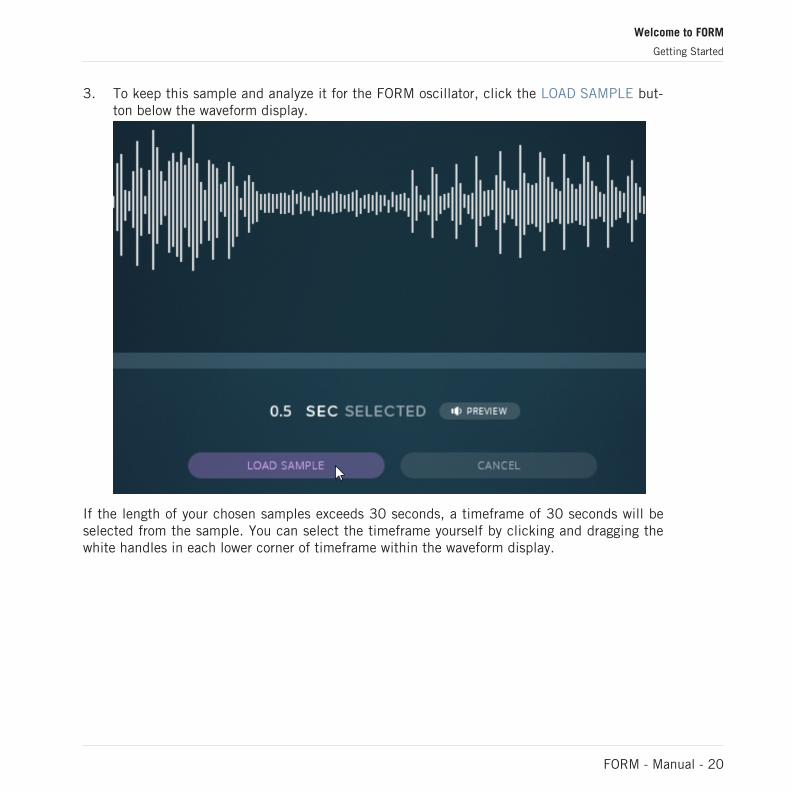
3. To keep this sample and analyze it for the FORM oscillator, click the LOAD SAMPLE but-ton below the waveform display.
If the length of your chosen samples exceeds 30 seconds, a timeframe of 30 seconds will beselected from the sample. You can select the timeframe yourself by clicking and dragging thewhite handles in each lower corner of timeframe within the waveform display.
Welcome to FORM
Getting Started
FORM - Manual - 20

For longer samples, a timeframe is selected for analysis
Once you have loaded a sample into FORM, click the LOAD SAMPLE button, and the instru-ment will analyze the audio content. Now you can apply FORM's Motion Curves to the audioand create complex and interesting new sounds. You can control and edit these Motion Curvesin a multitude of ways and even create your own. Furthermore, you can use the PERFORM sec-tion to save different Curves or even alternative variations of the Sound altogether and playthem back using a control octave on your MIDI keyboard.
► To learn more about the possibilities of FORM, continue reading this document.
Welcome to FORM
Getting Started
FORM - Manual - 21

2 Overview of the FORM Interface
FORM is an interesting instrument based on combining your own samples with FORM’s crea-tive Motion Curves. Start by loading a sample into the waveform display of the SAMPLE pageor on the SAMPLE SELECT page and selecting one of the provided Motion Curves in the MO-TION section at the center bottom of the interface. Once you have done so, you are already onthe way to experiencing the easy-to-use and yet extremely versatile power of FORM.
1
2
3
Overview of FORM's interface.
(1) The Header: This section lets you select the page to display in the Main section and holdscontrols for voicing and to influence the PERFORM section. For detailed information, see sec-tion ↑2.1, The Header.
(2) The Main section: The controls displayed here change depending on your selection in theHeader. The Main section displays the controls that are available for the SAMPLE, SOUND,and EFFECTS pages as well as the Motion Curve CURVE PRESETS and CURVE EDITOR. Fordetailed information, see ↑2.2, The Main Section.
Overview of the FORM Interface
FORM - Manual - 22

(3) The Footer: This area displays the SPEED, MOTION, and PERFORM sections as well as theMacro controls and is visible at all times. For detailed information, see section ↑2.3, The Foot-er.
2.1 The Header
The Header is located at the top of the interface. It is visible at all times and contains a selec-tor that lets you switch between pages to display at the Main section. Furthermore, the Headerholds controls for voicing and parameters relating to the PERFORM section.
1 2 3 4 5 6 7 8
9 10 11 12 13 14 15The Header
(1) FORM icon: Opens the product credits in the Main section.
(2) SAMPLE: Click this to display and access the waveform of the loaded sample.
(3) SOUND: Click this to access parameters for controlling FORM’s oscillators and to controlthe modulators and filters.
(4) EFFECTS: Click this to access FORM’s effects section. It contains both traditional effectslike reverb and delay and the new frequency shaping tool.
(5) EFFECTS OFF: Click to bypass all effect units of the EFFECTS page.
Overview of the FORM Interface
The Header
FORM - Manual - 23

(6) Key lock button: Switch this on to lock the EFFECTS OFF button to its current state (on oroff) while browsing through FORM's Presets. This means that you can audition FORM's Presetseither untouched or without effect units.
(7) TUNE: Drag the slider right or left to tune the master output up or down, respectively.
(8) VOL: The master volume slider lets you click and drag to set the output level.
(9) SAMPLE SELECT: Click this button to open the SAMPLE SELECT page, were you can loadand preview your samples.
(10) Voice selector: Select one of three voicing modes:
▪ POLY: Lets you play back your samples using two or more notes simultaneously.
▪ MONO RETRIG: Retriggers every note when you press a new key on your MIDI keyboard.
▪ MONO LEG: Retriggers only the first note of a chord when you press down keys on yourMIDI keyboard. Remaining note-on messages are ignored until all keys are released.
(11) GLIDE: Sets the amount of time it takes to transition from one note pitch to another.
(12) RESET PHASE: Activate to reset the phase of the oscillators when a key is pressed.
(13) SPREAD: Turn to set the pitch offset for each voice when in UNISON and MULTI MODE.
(14) Perform Voice selector: This lets you define how the PERFORM section will behave. Selectone of three different settings:
▪ SINGLE: This mode plays back one active Performance slot.
▪ UNISON: This mode plays back up to four versions of the active Performance slot, depend-ing on the setting of the Voice Amount button to the right of the Perform Voice selector.
▪ MULTI MODE: This mode plays back up to four different saved Performance slots simulta-neously. The Performance slots being played back are visually reflected in the PER-FORM section at the bottom right of the FORM interface.
(15) Voice Amount: Click this button to set a number (2-4) of voices for the Performance slotsto play back simultaneously in UNISON and MULTI MODE. When doing so, you are using mul-tiple voices to play one note, meaning that you are reducing the total amount of voices you canplay back simultaneously. Setting Voice Amount to 2 equals four available notes, whereas set-ting it to 4 gives you two simultaneously playable notes.
Overview of the FORM Interface
The Header
FORM - Manual - 24

2.2 The Main Section
The Main section displays parameters belonging either to the SAMPLE, SOUND, or EF-FECTS page, depending on your selection in the Header. This is also the section where you canbrowse and edit Motion Curves in detail using the CURVE EDITOR.
The Main section gives you controls to shape the sound of your sample into something com-pletely different. Using the selector in the Header you can display and control parameters ei-ther for the SAMPLE, SOUND, or EFFECTS page.
The SAMPLE Page
The SAMPLE page
The SAMPLE page lets you select and load your samples via drag-and-drop. For more detailedinformation, see section ↑3, The SAMPLE Page.
The SOUND Page
Overview of the FORM Interface
The Main Section
FORM - Manual - 25

The SOUND page
The SOUND page lets you shape, edit and modulate the sound of your sample. For more de-tailed information, see section ↑4, The SOUND Page.
The EFFECTS Page
Overview of the FORM Interface
The Main Section
FORM - Manual - 26

The EFFECTS page with effect units switched on
The EFFECTS page lets you further control your output by giving you access to a set of classicand creative effects. For more detailed information, see section ↑5, The EFFECTS Page.
The CURVE EDITOR
Overview of the FORM Interface
The Main Section
FORM - Manual - 27
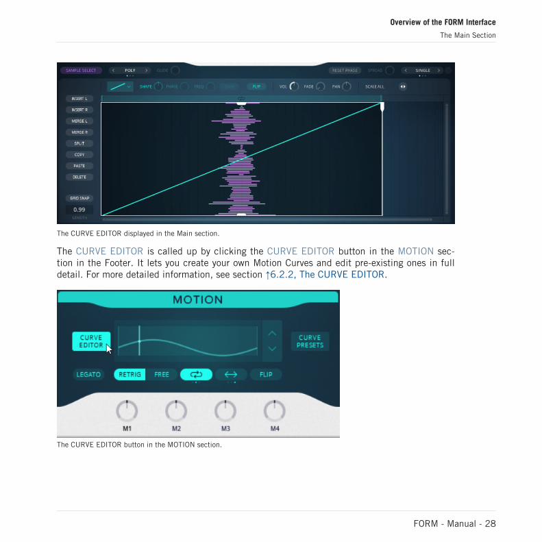
The CURVE EDITOR displayed in the Main section.
The CURVE EDITOR is called up by clicking the CURVE EDITOR button in the MOTION sec-tion in the Footer. It lets you create your own Motion Curves and edit pre-existing ones in fulldetail. For more detailed information, see section ↑6.2.2, The CURVE EDITOR.
The CURVE EDITOR button in the MOTION section.
Overview of the FORM Interface
The Main Section
FORM - Manual - 28

2.3 The Footer
This area contains the SPEED, MOTION, and PERFORM sections as well as the Macro con-trols. The Footer area is visible at all times, regardless of what parameters you are monitoringin the Main section. The controls are split into three sections, each controlling a different as-pect of the sound.
1 2 3
4 5 6The Footer
(1) SPEED: This section contains controls for playback speed.
(2) MOTION: This section contains controls for the Motion Curves.
(3) PERFORM: This section contains controls for playing and saving variations of the Sound intwelve Performance slots.
(4) RESET SOUND: Click to reset all of FORM's parameters to default, effectively clearing theSound.
(5) Macro controls: The Macro controls can be assigned as modulation sources for any ofFORM’s parameter available for modulation. You can set polarity and select one the availablelabels to organize your macros according to their modulation destinations.
(6) MOD AMOUNT: This slider sets the total amount of modulation being sent to all destina-tions simultaneously.
Overview of the FORM Interface
The Footer
FORM - Manual - 29
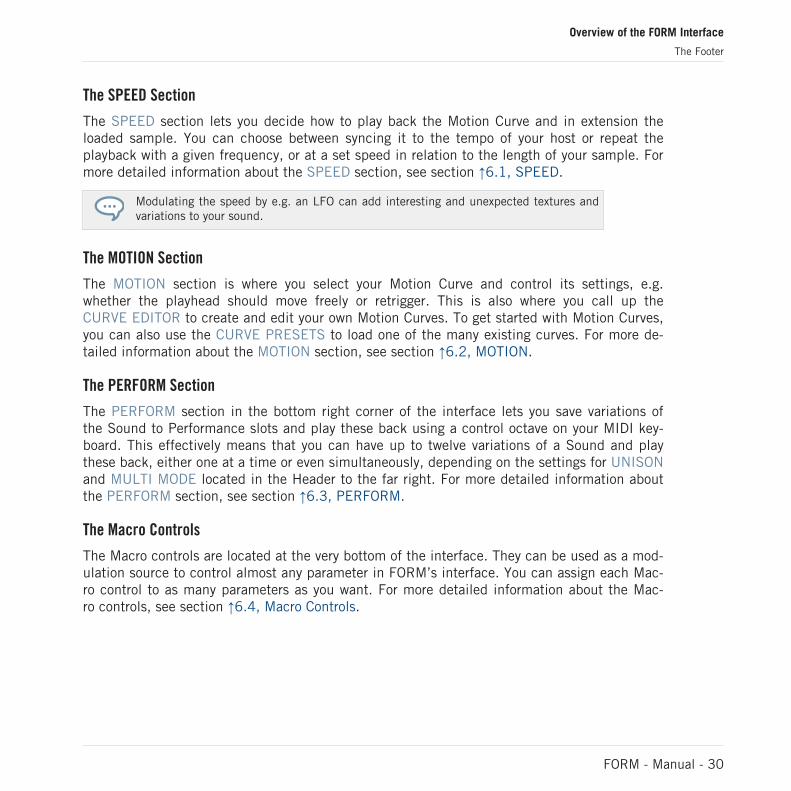
The SPEED Section
The SPEED section lets you decide how to play back the Motion Curve and in extension theloaded sample. You can choose between syncing it to the tempo of your host or repeat theplayback with a given frequency, or at a set speed in relation to the length of your sample. Formore detailed information about the SPEED section, see section ↑6.1, SPEED.
Modulating the speed by e.g. an LFO can add interesting and unexpected textures andvariations to your sound.
The MOTION Section
The MOTION section is where you select your Motion Curve and control its settings, e.g.whether the playhead should move freely or retrigger. This is also where you call up theCURVE EDITOR to create and edit your own Motion Curves. To get started with Motion Curves,you can also use the CURVE PRESETS to load one of the many existing curves. For more de-tailed information about the MOTION section, see section ↑6.2, MOTION.
The PERFORM Section
The PERFORM section in the bottom right corner of the interface lets you save variations ofthe Sound to Performance slots and play these back using a control octave on your MIDI key-board. This effectively means that you can have up to twelve variations of a Sound and playthese back, either one at a time or even simultaneously, depending on the settings for UNISONand MULTI MODE located in the Header to the far right. For more detailed information aboutthe PERFORM section, see section ↑6.3, PERFORM.
The Macro Controls
The Macro controls are located at the very bottom of the interface. They can be used as a mod-ulation source to control almost any parameter in FORM’s interface. You can assign each Mac-ro control to as many parameters as you want. For more detailed information about the Mac-ro controls, see section ↑6.4, Macro Controls.
Overview of the FORM Interface
The Footer
FORM - Manual - 30

3 The SAMPLE Page
The SAMPLE page displays the waveform of your loaded sample. Just as with the SAMPLE SE-LECT page, you can drag and drop samples directly into the Waveform display on the SAM-PLE page. You can also select a defined time frame of your sample by clicking and draggingthe handles in each of the bottom corners of the Waveform display.
To display the pitch curve of your sample, click the PITCH CURVE button in the upper rightcorner of the Waveform display. Note that the PITCH CURVE button is only available on theSAMPLE page and not on the similar SAMPLE SELECT page. Displaying the pitch curve canbe helpful when deciding on a time frame for your sample, as you may end up with different-sounding timbres depending on the pitch of the loaded sample. Furthermore, it can be used asa modulation source for other parameters.
1. To load a sample into the SAMPLE page, click and drag a sample from the REAKTORbrowser into FORM's Waveform display.
⇨ The SAMPLE SELECT page will open automatically.
The SAMPLE Page
FORM - Manual - 31

2. To load the sample and analyze its audio content in order to use it for synthesis, click theLOAD SAMPLE button.
► To display the PITCH CURVE, click the PITCH CURVE button to the far right.
The SAMPLE Page
FORM - Manual - 32

► To manually set the location of the play head along the time axis, click and drag theTouch Strip icon in the upper right corner of the Waveform display until a play head ap-pears.
The SAMPLE Page
FORM - Manual - 33

► To limit your sample to a certain portion, click and drag the mouse up or down until youhave set the desired time window.
The SAMPLE Page
FORM - Manual - 34
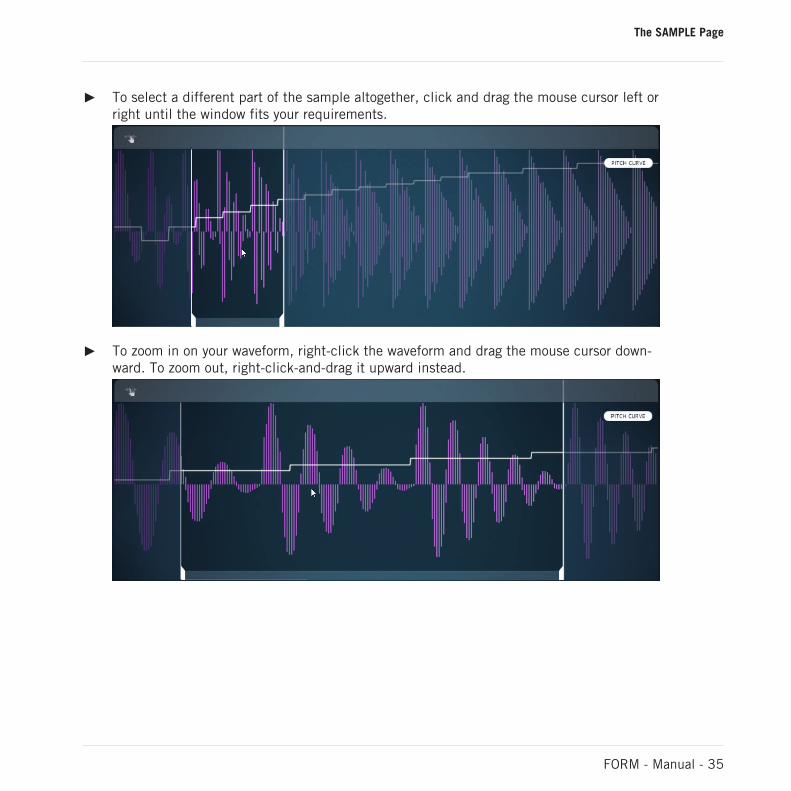
► To select a different part of the sample altogether, click and drag the mouse cursor left orright until the window fits your requirements.
► To zoom in on your waveform, right-click the waveform and drag the mouse cursor down-ward. To zoom out, right-click-and-drag it upward instead.
The SAMPLE Page
FORM - Manual - 35

► To move the visual part of the waveform sideways while zoomed in, right-click the wave-form and drag the mouse cursor left or right.
Whenever FORM is playing back your sample, the SAMPLE page indicates where the play headis located at any given point. This can be especially helpful if you are using a Motion Curvethat loops, or if you are modulating the playback speed.
The SAMPLE Page
FORM - Manual - 36

4 The SOUND Page
Use the controls on the SOUND page to precisely shape the sound you are looking for, and tomodulate parameters and thus make the sound evolve over time. To open the SOUND page,click SOUND in the Page selector in the Header.
The SOUND page is divided into five separate sections, each with its own controls. It is worthnoting, however, that certain controls, e.g., the DEFORM knob in the OSC FX section greatlyinfluence the controls of the FORM OSC section. Likewise, the controls in the MODULA-TION section can be assigned to modulate just about any parameter of the FORM instrument.To learn more about the sections of the SOUND page, keep reading below.
3
1
2
4
5
The SOUND page
(1) FORM OSC: This section gives you control over frequency-related parameters, such asPITCH and FORMANT.
(2) ADDITIVE OSC: This section lets you add another oscillator to mix with the sample youloaded in order to create a more powerful sounding output. The ADDITIVE OSC is also used asa modulator for FM modulation of the OSC FX unit.
The SOUND Page
FORM - Manual - 37

(3) OSC FX: This section holds parameters controlling the output sound. Controls for FM andstereo modulation are available, and you can also choose the degree to which you want to de-form the sound entirely.
(4) MODULATION: This section contains an advanced collection of modulators, ranging fromenvelopes and LFOs to creative side-chain modulation, in which two modulators e.g. multiplyeach other, with the resulting signal being used to modulate any other parameter of FORM.
(5) FILTER: This section contains a polyphonic multimode filter with corresponding controls.
4.1 The FORM OSC Section
The FORM OSC section is where you can control the output of FORM’s audio engine. FORManalyzes the audio content of your sample and then uses it to synthesize new sounds. In theFORM OSC section you can set parameters relating to FORM’s audio engine, such as pitchtracking and formant fine-tuning.
The SOUND Page
The FORM OSC Section
FORM - Manual - 38
1
2
3
4
5
6
7
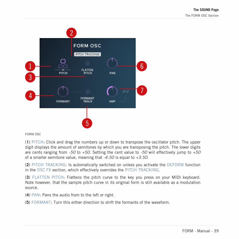
FORM OSC
(1) PITCH: Click and drag the numbers up or down to transpose the oscillator pitch. The upperdigit displays the amount of semitones by which you are transposing the pitch. The lower digitsare cents ranging from -50 to +50. Setting the cent value to -50 will effectively jump to +50of a smaller semitone value, meaning that -4.50 is equal to +3.50.
(2) PITCH TRACKING: Is automatically switched on unless you activate the DEFORM functionin the OSC FX section, which effectively overrides the PITCH TRACKING.
(3) FLATTEN PITCH: Flattens the pitch curve to the key you press on your MIDI keyboard.Note however, that the sample pitch curve in its original form is still available as a modulationsource.
(4) PAN: Pans the audio from to the left or right.
(5) FORMANT: Turn this either direction to shift the formants of the waveform.
The SOUND Page
The FORM OSC Section
FORM - Manual - 39

(6) FORMANT TRACK: Switch this on to adjust the formant of the waveform automatically inrelation to the pitch of each note.
(7) AMP: Sets the amplification level for the FORM OSC. The amplifier is hardwired to the en-velope ENV1 in the MODULATION section of the SOUND page.
4.2 ADDITIVE OSC
As some samples lack audio content in certain areas of the frequency spectrum, FORM comesequipped with an extra oscillator that can be used to fill out your sounds. Use it to achievericher sounds in the frequencies corresponding to the level set by the OCTAVE control.
1 2 3ADDITIVE OSC
(1) OCTAVE: Click and drag to add a set of predefined harmonic pitch offsets in relation to theFORM OSC. This can be useful for adding bass as well as for driving frequency modulation,which is set by the FM knob in the OSC FX section (see section ↑4.3, OSC FX).
(2) WAVEFORM: Turn this control to set the waveform of the additive oscillator. For a pure sinewaveform, turn the knob all the way to the left end stop. For a soft saw-type waveform, set theknob to the center position. For a soft square-type waveform, turn the knob all the way to theright end stop.
The SOUND Page
ADDITIVE OSC
FORM - Manual - 40

(3) VOLUME: Sets the volume of the additive oscillator.
4.3 OSC FX
The OSC FX section contains controls for shaping FORM's oscillator, such as frequency modu-lation and a wide stereo effect. The display at the center of the section visualizes the oscilla-tions playing in real time.
1
23
4 5 6OSC FX
(1) DEFORM on/off: This switch activates or deactivates the DEFORM function, which effec-tively overrides the PITCH TRACKING function of the FORM OSC section. Doing so flattens thepitch, regardless of the setting in the FORM OSC section, and lets you use the DEFORM knobto destruct the sound.
(2) DEFORM knob: Turn this knob in either direction to set a pitch and manually introduce atype of sonic destruction effect that effectively deforms your sound.
(3) SHAPER: Turn this knob clockwise to shape the waveform segments in FORM's oscillator.
The SOUND Page
OSC FX
FORM - Manual - 41

(4) FM: Turn this knob clockwise to set the level of frequency modulation by which the ADDI-TIVE OSC FM modulates the FORM OSC.
(5) STEREO: This bipolar knob jitters the play head position between the left and right chan-nels.
(6) MULTIPLY: Turn this knob clockwise to increasingly compress the waveform and introducemore harmonic content.
4.4 MODULATION
The advanced MODULATION section lets you assign and define modulation and even cross-modulation of almost any parameter in FORM’s interface, particularly on the SOUND and EF-FECTS pages, but also in the SPEED section. Modulation is defined as an offset to the set val-ue of each destination parameter, and is indicated by a white pin just outside the interface el-ement. The indicator moves to reflect the speed and set depth of the modulation source.
MODULATION
The SOUND Page
MODULATION
FORM - Manual - 42

Modulators
There are five different modulators available in the MODULATION section. It is worth noting,however, that many more modulation sources can be used, such as FORM’s Motion Curves, themacro controls in the Footer, and the pitch-bend wheel on your MIDI keyboard. Each modula-tor can be assigned to as many destinations as you want.
The modulator selector lets you select which modulator to display, but all modulators are ac-tive simultaneously. Available modulators are ENV1, ENV2, LFO1, LFO2, and SC. Both enve-lopes and both LFOs are identical in terms of provided controls, and the side-chain modulatorallows you to combine the signals of two of the other modulators and use the resulting outputsignal as source for modulation assignment.
4.4.1 ENV
ENV1 and ENV2 are identical in terms of available parameters. They come equipped withknobs for attack, decay, sustain, and decay, as well as a velocity control. Note however, thatENV1 is automatically assigned to the AMP knob in the FORM OSC section of theSOUND page. This means that ENV1 always sets the amplitude envelope of the oscillator andthus can have a great influence on the output sound.
21
3 4 5 6 7ENV
The SOUND Page
MODULATION
FORM - Manual - 43

(1) Envelope display: The shape of the envelope is displayed here. If envelope parameters arebeing controlled by other modulators, the modulation will be reflected as an offset to the enve-lope in real time.
(2) Envelope indicator: This indicator reflects the velocity at which the envelope moves througheach of its phases.
(3) ATT: Turn this to set the attack time of the envelope.
(4) DEC: Turn this to set the decay time of the envelope.
(5) SUS: Turn this to set the sustain level of the envelope.
(6) REL: Turn this to set the release time of the envelope.
(7) VEL: Turn this to set the velocity sensitivity with which the entire envelope moves throughall its phases.
4.4.2 LFO
LFO1 and LFO2 are both identical in terms of available parameters. They each come equippedwith four different waveforms that can be further defined using the SHAPE control, as well asparameters for SPEED and PHASE.
123
4
5 6 7 8LFO
The SOUND Page
MODULATION
FORM - Manual - 44

(1) Waveform selector: Select one of the four different waveforms. Available for selection aresine, tri, square, and random. Each of these can be defined in further detail using the SHAPEcontrol. The selected waveform, in its form set by the SHAPE control, is reflected by the wave-form display.
(2) Waveform display: The shape of the LFO signal is reflected visually here.
(3) LFO indicator: This indicator reflects the speed at which the LFO moves through its oscilla-tions. Every time the signal passes the zero crossing, at the velocity set by the SPEED control,the polarity switches. If the waveform selector is set to random, the LFO indicator will moverandomly.
(4) PHASE: Turn this to shift the starting position of the phase in the LFO signal along thetime axis.
(5) HZ|BPM: Select either Hz or note values as scale for the SPEED control.
(6) SPEED: Turn this to set the speed at which the LFO operates. Depending on your selection,the SPEED can be set either in Hz or as a note value (BPM), ranging from either 0 to 30 Hz or32 Bar to 1/96 note, respectively.
(7) TRIG|FREE: Select either triggering or free mode for the SHAPE control. When set to FREE,LFO phases can differ from one polyphonic voice to another.
(8) SHAPE: Turn this to further define the shape of the LFO waveform.
▪ For sine, SHAPE moves from spike wave at fully left, via sine at center, to pulse or squareat fully right.
▪ For tri, SHAPE moves from falling saw at fully left, via triangle at center, to rising saw atfully right.
▪ For square, SHAPE acts as pulse-width control.
▪ For random, SHAPE moves from time-wise random signal at fully left, via stepped randomsignal at center, to smooth-edged random signal at fully right.
The SOUND Page
MODULATION
FORM - Manual - 45

4.4.3 SC
The side-chain modulator uses two modulators as sources and uses their corresponding outputsignals as input signals. The input signals are then combined, either by multiplication or bycrossfading. The resulting signal can then be used as output modulation signal for modulationassignment to other parameters.
1 2
3 4SC
(1) Modulator slots: Click each of these slots to open its modulation assignment menu, which dis-plays all available modulators for the slot. Select one of the modulators from the menu for thecorresponding slot by clicking their buttons in the menu.
(2) Signal display: The shape of the resulting output signal is reflected here.
(3) MULTIPLY|CROSSFADE: Select the algorithm mode by which the SC modulator will com-bine the two modulation signals. MULTIPLY takes the signal from each modulator and multi-plies their values by each other, whereas CROSSFADE switches back and forth between thesignals.
The SOUND Page
MODULATION
FORM - Manual - 46

(4) AMT: In MULTIPLY mode, this knob fades from outputting only the modulator in the leftslot at fully left, to full multiplication of both modulation sources when set fully right. InCROSSFADE mode, the AMT knob functions as a crossfader.
Selecting a modulator as input
4.4.4 Assigning Modulation
Any FORM parameter that is available for modulation can be assigned to up to three modula-tion sources simultaneously. To do so, follow the steps below.
The SOUND Page
MODULATION
FORM - Manual - 47

1. To open the modulation assignment menu, click the parameter label directly below theparameter.
The modulation assignment menu will open and display the three modulation slots for thechosen parameter.
The SOUND Page
MODULATION
FORM - Manual - 48

2. To select a modulation source, click one of the three modulation slots and the modula-tion source menu will open.
The SOUND Page
MODULATION
FORM - Manual - 49

► To see the available sources, you can choose between MAIN and MACRO. Choosing MAINwill display the five modulation sources available in the MODULATION section of theSOUND page, as well as VELO for velocity, KEYTR. for key-tracking, PB for pitch-bend,AT for aftertouch, and MW for modulation wheel. Choosing MACRO instead displays thefour macro controls, PITCH CURVE for the pitch curve of the loaded sample, and MO-TION CURVE for the Motion Curve that is active in the MOTION section.
The SOUND Page
MODULATION
FORM - Manual - 50
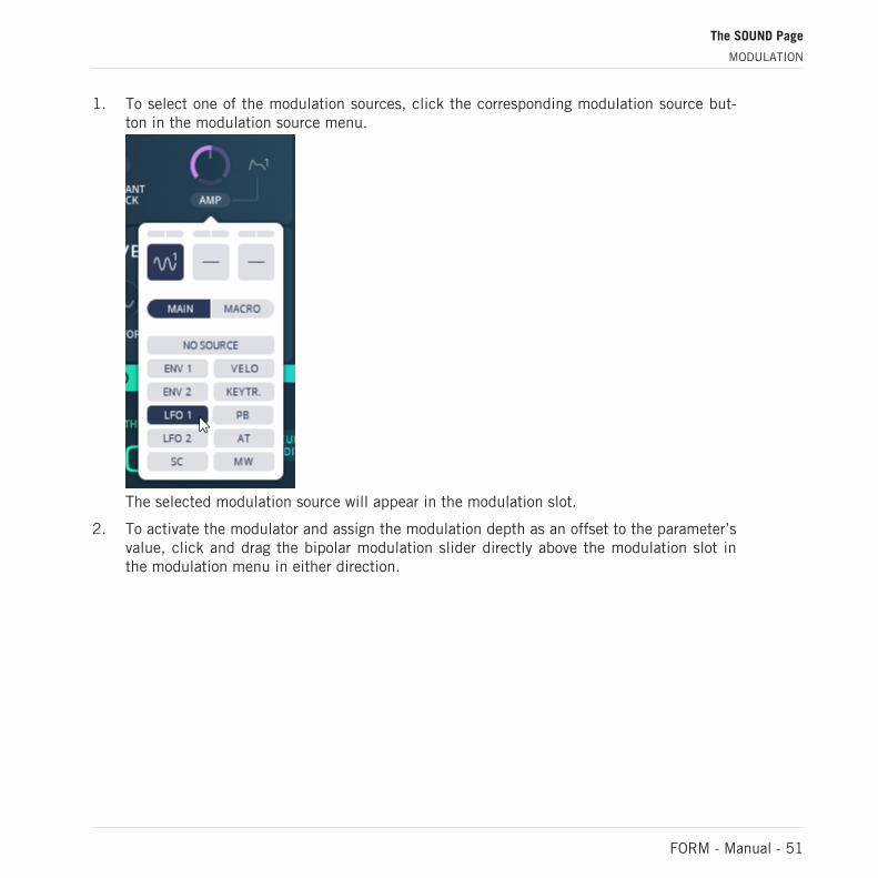
1. To select one of the modulation sources, click the corresponding modulation source but-ton in the modulation source menu.
The selected modulation source will appear in the modulation slot.
2. To activate the modulator and assign the modulation depth as an offset to the parameter’svalue, click and drag the bipolar modulation slider directly above the modulation slot inthe modulation menu in either direction.
The SOUND Page
MODULATION
FORM - Manual - 51

The parameter is now assigned as modulation destination and the modulation offset is vi-sualized by an indicator moving at the corresponding speed of the modulation source.
The SOUND Page
MODULATION
FORM - Manual - 52

► To assign a second or third modulation source, repeat the above steps using anothermodulation slot in the modulation menu.
► To close the modulation menu, click the parameter label directly below the parameter.
The SOUND Page
MODULATION
FORM - Manual - 53
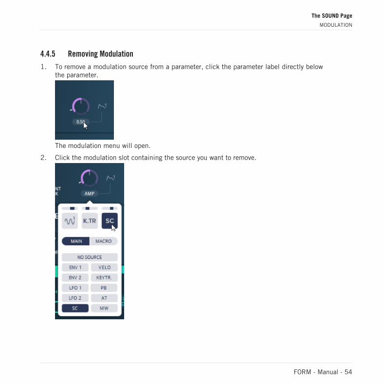
4.4.5 Removing Modulation
1. To remove a modulation source from a parameter, click the parameter label directly belowthe parameter.
The modulation menu will open.
2. Click the modulation slot containing the source you want to remove.
The SOUND Page
MODULATION
FORM - Manual - 54

3. To remove the modulation source, click the NO SOURCE button in the modulation menu.
The SOUND Page
MODULATION
FORM - Manual - 55

4. To remove all modulation sources, repeat the previous step until all modulation slots areempty.
For any and all of the modulators to send modulation signals, the MOD AMOUNT slider at thebottom right of the interface must be set to a value larger than 0. That is, if you click and dragthe MOD AMOUNT slider fully left, all modulation is simultaneously switched off.
For information about the Macro controls, see section ↑6.4, Macro Controls.
4.4.6 Modulating Modulator Parameters
Just as with other parameters available for modulation, the parameters of the modulatorsthemselves can be assigned as modulation destinations. Modulators can be assigned to controlboth their own parameters and those of other modulators. This means that you can, for exam-ple, let LFO1 control its own SPEED, and simultaneously also the SPEED parameter of LFO2.LFO2 in turn can be assigned to control both its own SHAPE and PHASE parameters and thoseof LFO1. By doing so, you will have LFO1 controlling the SPEED at which both LFOs set theirSHAPE and PHASE parameters. Each of these two LFOs can then be assigned to as many oth-
The SOUND Page
MODULATION
FORM - Manual - 56

er FORM parameters as you like. Beyond this, you can even use the two LFOs to multiply orcrossfade each other’s signals using the SC modulator. There is an almost unlimited amount ofpossible ways to modulate and cross-modulate the parameters of FORM to create sound tex-tures that develop and change over a given time period.
Assigning modulation to a modulator parameter
For information on how to assign parameters for to a modulation source, see section ↑4.4.4,Assigning Modulation.
The SOUND Page
MODULATION
FORM - Manual - 57

4.5 FILTER
The FILTER section provides a polyphonic multimode filter with low-pass, high-pass, andnotch modes.
1 2 3FILTER
(1) MODE: This selector lets you switch between LP, HP, and NOTCH modes.
▪ LP: Low-pass filtering lets you filter out audio content above the frequency set by the CUT-OFF knob.
▪ HP: High-pass filtering lets you filter out audio content below the frequency set by theCUTOFF knob.
▪ NOTCH: Band-stop filtering lets you filter out audio content within a narrow frequency spancentered on the frequency set by the CUTOFF knob.
(2) CUTOFF: Sets the cutoff frequency for the LP and HP modes and the center frequency forthe NOTCH mode.
(3) RESONANCE: Sets the amount of resonance at the cutoff frequency.
The SOUND Page
FILTER
FORM - Manual - 58

5 The EFFECTS Page
FORM's EFFECTS page is equipped with traditional effect units for compression, delay, and re-verb, but also a new FREQUENCY SHAPING unit that lets you select specific frequency spec-tra and boost, mitigate, or distort these.
1 2
3 4 5EFFECTS
(1) FREQUENCY SHAPING: This section can be seen as an advanced multiband filter, whereyou can set two different frequency bands and attenuate or diminish the output of these fre-quencies. See section ↑5.1, FREQUENCY SHAPING.
(2) WARMTH (only available with FREQUENCY SHAPING switched on): Use this section to addan overdrive effect and add warmth to the output. See section ↑5.2, WARMTH.
(3) DYNAMICS: This is FORM's compressor, which can be used to control the dynamic range.See section ↑5.3, DYNAMICS.
(4) DELAY: A delay unit with settings for both ping pong and standard delay. See section ↑5.4,DELAY.
(5) REVERB: A reverb unit with five different room settings as well as filter controls. See sec-tion ↑5.5, REVERB.
The EFFECTS Page
FORM - Manual - 59

5.1 FREQUENCY SHAPING
The FREQUENCY SHAPING unit lets you select specific bands of the frequency spectrum andcontrol these. The bands are represented visually by blue and purple bars and their sizes andshapes can easily be set and modulated via the knobs on the left side of the unit.
1
2
3 4
5 6 7 8
9
FREQUENCY SHAPING
(1) FREQUENCY SHAPER button: Switches the effect unit on or off.
(2) DRY/WET BAND FILTER: Turn to mix between dry signal and the wet signal filtered by thefrequency bands.
(3) BAND 1: Controls for BAND 1, visually reflected as blue band by the Band display.
(4) BAND 2: Controls for BAND 2, visually reflected as purple band by the Band display.
(5) LEVEL: Set the amount of frequency shaping for the corresponding frequency band.
(6) CENTER: Set the center position along the frequency spectrum for the corresponding fre-quency band.
(7) WIDTH: Set the bandwidth or the corresponding frequency band.
The EFFECTS Page
FREQUENCY SHAPING
FORM - Manual - 60

(8) Band display: Visually reflects the settings of the BAND 1 and BAND 2 settings as blue andpurple bars, respectively. Click and drag the bands to set the LEVEL knobs. When the parame-ters are modulated, a fluctuating offset is visible for each frequency band bar.
(9) PHASE: Adjust the phase cancellation between the dry and wet signals.
5.2 WARMTH
The WARMTH unit is only available when the FREQUENCY SHAPING unit is switched on. Itadds saturation and color to the sound.
1
2
3
4 5
6
WARMTH
(1) WARMTH button: Switches the effect unit on or off.
(2) ALL: Select this to apply the WARMTH effect to the entire frequency spectrum after thesignal has been processed by the FREQUENCY SHAPING unit.
(3) BANDS: Select this to apply the WARMTH effect only to the frequency spectrum selectedby the bands in the FREQUENCY SHAPING effect unit, whereas the dry signal is not affected.
(4) Mode selector: Click the arrows to switch between the available modes.
▪ DIGITAL: Applies digital distortion to the input signal.
The EFFECTS Page
WARMTH
FORM - Manual - 61

▪ TUBE: Applies overdriven saturation the input signal.
(5) DRIVE: Turn to apply input amplification to drive the distortion effect.
(6) CHARGE: Tweak the character of the signal from soft at fully left to hard at fully right.
5.3 DYNAMICS
The DYNAMICS effect is a compression unit that gives you full control of the dynamic range ofthe signal. The DYNAMICS unit is located as the first unit in FORM's FX chain.
1
2
3 4 5 6DYNAMICS
(1) DYNAMICS button: Switches the effect unit on or off.
(2) Level meter: Displays the amount of compression being applied to the input signal.
(3) ATTACK: Turn to set the time of the attack phase.
(4) RELEASE: Turn to set the time of the release phase.
(5) RATIO: Turn to set the amount of gain reduction at the input.
The EFFECTS Page
DYNAMICS
FORM - Manual - 62
(6) OUTPUT GAIN: Turn to set the output gain level.
5.4 DELAY
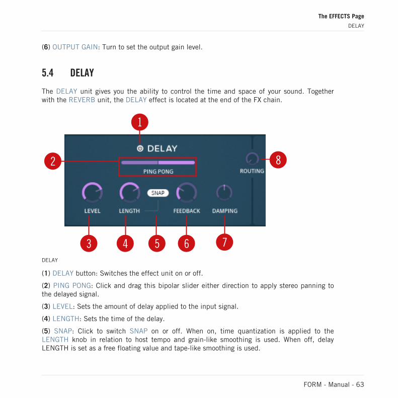
The DELAY unit gives you the ability to control the time and space of your sound. Togetherwith the REVERB unit, the DELAY effect is located at the end of the FX chain.
1
2
3 4 5 6 7
8
DELAY
(1) DELAY button: Switches the effect unit on or off.
(2) PING PONG: Click and drag this bipolar slider either direction to apply stereo panning tothe delayed signal.
(3) LEVEL: Sets the amount of delay applied to the input signal.
(4) LENGTH: Sets the time of the delay.
(5) SNAP: Click to switch SNAP on or off. When on, time quantization is applied to theLENGTH knob in relation to host tempo and grain-like smoothing is used. When off, delayLENGTH is set as a free floating value and tape-like smoothing is used.
The EFFECTS Page
DELAY
FORM - Manual - 63

(6) FEEDBACK: Sets the amount of delay feedback signal.
(7) DAMPING: Sets the amount of filtering. Turn anticlockwise for low-shelf damping andclockwise for high-shelf damping.
(8) ROUTING (only available if REVERB is simultaneously switched on): Set fully left to routethe DELAY and REVERB units in serial DELAY—REVERB mode, via parallel at center positionto DELAY—REVERB at fully right.
5.5 REVERB
The REVERB unit lets you control the size of the sound and its position in the mix. Togetherwith the DELAY unit it is located at the end of the FX chain.
1
23
4 5 6 7REVERB
(1) REVERB button: Switches the effect unit on or off.
The EFFECTS Page
REVERB
FORM - Manual - 64

(2) ROUTING (only available if DELAY is simultaneously switched on): Set fully left to routethe DELAY and REVERB units in serial DELAY—REVERB mode, via parallel at center positionto DELAY—REVERB at fully right.
(3) Room size selector: Click the arrows to switch between reverb types. Available types are:
▪ SMALL
▪ LARGE
▪ SPACE
▪ CHEAP
▪ UNREAL
▪ (4) LEVEL: Sets the amount of reverb being applied to the input signal.
▪ (5) SIZE: Sets the room size.
▪ (6) LO DAMP: Sets the amount of high-pass filtering of the reverb tail.
▪ (7) HI DAMP: Sets the amount of low-pass filtering of the reverb tail.
The EFFECTS Page
REVERB
FORM - Manual - 65

6 The Footer
The Footer contains controls that let you control the playback tempo in the SPEED section(↑6.1, SPEED), the behavior of the Motion Curve in the MOTION section (↑6.2, MOTION), andthe act of saving and playing back the Performance slots in the PERFORM section (↑6.3, PER-FORM).
The Footer with its sections
6.1 SPEED
The SPEED section contains controls for setting playback speed as a factor multiplied by ei-ther the length of the sample, by cycles per second, or by the BPM of your DAW, depending onthe settings you select. The values can be assigned as modulation destinations, which can addinteresting textures and IDM-like tempo changes.
The Footer
SPEED
FORM - Manual - 66

1
2 3
4The SPEED section
(1) Speed label: Depending on the time base selected, this label depicts either SAM-PLE LENGTH (for SAMPLE), CYCLES/SEC (for HZ), or SYNC SPEED (for BPM). Click the labelto assign modulation to the SPEED controls.
(2) Speed: Click and drag the numbers to set the speed as a factor multiplied by the selectedtime base (SAMPLE, HZ, or BPM).
(3) SNAP (available for SAMPLE and BPM): Switch on to snap the value to the nearest availa-ble value, from 0, 1/16, 1/8, 1/4, 1/2, 1, 2, 4, 8 to 16.
(4) Time base selector: Select the type of factor that will be multiplied by the value set by thenumbers in the Speed control. Available are SAMPLE, HZ, and BPM:
▪ SAMPLE: Motion Curve playback speed is set in relation to original sample playback speed.
▪ HZ: Motion Curve playback speed is set in cycles per second.
▪ BPM: Motion Curve playback is set based on host tempo.
The Footer
SPEED
FORM - Manual - 67

6.2 MOTION
The MOTION section is located in the Footer and contains controls for FORM’s Motion Curves.Use the controls to define the behavior of the play head and the Motion Curve. The parametersin the MOTION section cannot be assigned as modulations destinations, but the Motion Curvesthemselves can be used as modulation sources and be assigned to other parameters.
1
2 3
4
5 6 7 8 9 10The MOTION section
(1) CURVE EDITOR: Click this button to call up the CURVE EDITOR at the Main section. TheCURVE EDITOR is an advanced Motion Curve creation environment where you can edit yourown Curves. For more detailed information, see section ↑6.2.2, The CURVE EDITOR.
(2) The Motion Curve display: The active Motion Curve for one of the Performance slots (see sec-tion ↑6.3, PERFORM) is displayed here together with the loop range and the current play headposition.
(3) The Motion Curve selector: Click the up and down arrow buttons to switch to the next Mo-tion Curve slot from the CURVE PRESETS.
(4) CURVE PRESETS: Click this button to call up the CURVE PRESETS at the Main section.The CURVE PRESETS lets you see all saved Motion Curves and also enter WRITE MODE tosave your own Motion Curves.
The Footer
MOTION
FORM - Manual - 68

(5) LEGATO (only available in RETRIG mode): Switch this on to activate LEGATO mode, inwhich only the first MIDI note-on retriggers the Motion Curve playback.
(6) RETRIG: Switch this on to enter RETRIG mode, in which MIDI note-on automatically retrig-gers Motion Curve playback.
(7) FREE: Switch this on to enter FREE mode, in which the Motion Curve plays and loops con-tinuously. MIDI note-on messages are ignored, so pressing down a key on your MIDI keyboardwill play back the sample from the position of the Motion Curve where the play head is locatedat the time.
(8) Loop (only available in RETRIG mode): Controls the looping behavior of the Motion Curve.The range of the Motion Curve that will be looped is visually reflected by the Motion Curve dis-play as an overlay and can be adjusted in the CURVE EDITOR. Available modes are:
▪ Off
▪ Continue loop on note-off: The play head continues to loop within the loop range even afterthe note has been released.
▪ Leave loop on note-off: The play head leaves the loop as soon as you release the note.
(9) Loop direction (only available in RETRIG mode): This controls the loop behavior for FREEand RETRIG modes. Select between three modes of loop direction:
▪ Forward: From left to right.
▪ Backward: From right to left.
▪ Pendulum: From left to right and then right to left, repeatedly.
▪ (9) SYNC (only available in FREE mode): Activate to sync the play head position in the Mo-tion Curve for all polyphonic voices simultaneously.
(10) FLIP: Click to invert the entire Motion Curve horizontally.
6.2.1 The CURVE PRESETS
The CURVE PRESETS can be found by clicking the CURVE PRESETS button in the MO-TION section. This is where all Motion Curves are saved and can be loaded for use togetherwith your samples.
The Footer
MOTION
FORM - Manual - 69

1
2The CURVE PRESETS
(1) Motion Curve slots: Click the slots to select the corresponding Motion Curves.
(2) Page buttons: Click the left and right page buttons to open the previous or next page.
6.2.2 The CURVE EDITOR
You can use the CURVE EDITOR to create own Motion Curves.
The Footer
MOTION
FORM - Manual - 70

► To call up the CURVE EDITOR at the Main section, click the CURVE EDITOR button inthe MOTION section of the Footer.
The Footer
MOTION
FORM - Manual - 71

→ The CURVE EDITOR opens with the active Motion Curve loaded.
The parameters of the CURVE EDITOR cannot be modulated. You can however use the result-ing Motion Curve as a modulator and assign it to other parameters. This will let you control themotion behavior of the modulation destination, similar to a complex envelope.
All parameters available in the CURVE EDITOR are described below.
The Footer
MOTION
FORM - Manual - 72

1 2 3 4 5 6 7 8 9 10
11
12
13
14
1516
17
18
19
20
21
22
23
The CURVE EDITOR
(1) Curve menu: Click the drop-down menu and select the corresponding Motion Curve to load itinto the active segment in the editor. Depending on which curve you select, different knobswill be available for editing (SHAPE, PHASE, and FREQ). VOL, FADE, and PAN are availablefor all curves. The first five waveforms in the menu will play back once per segment, whereasrepeating waveforms (the bottom three) can be altered using the FREQ knob and the LENGTHcontrol to play back multiple times, creating for example a pulse-like behavior. The availableCurves are:
▪ Flat line
▪ Rising line
▪ Double curve
▪ Triangle
▪ Sine
▪ Repeating line
▪ Repeating Triangle
▪ Repeating Sine
The Footer
MOTION
FORM - Manual - 73

(2) SHAPE: Turn this knob either direction to further define the shape of the waveform select-ed by the Curve menu. SHAPE works similar to a pulse-width control in that it edits the shapeof the waveforms between the waveforms’ peaks, for example by adding a curve shape to anotherwise straight line.
(3) PHASE: Turn this knob either direction to shift the phase of the waveform along the timeaxis.
(4) FREQ (available for repeating waveforms): Turn this knob either direction to set the amountof repetitions within a segment.
(5) SNAP (available for repeating waveforms): Switch on to snap the FREQ knob to a grid.
(6) FLIP: Click to invert the entire Motion Curve horizontally.
(7) VOL: Set the output level for the segment.
(8) FADE: Turn clockwise to set a longer attack phase for the segment.
(9) PAN: Turn either direction to pan the output audio to the corresponding side during play-back of the segment.
(10) SCALE ALL: Click and drag the arrow button up or down to set the LENGTH of the seg-ment. This is mostly interesting for repeating waveforms, where increasing the LENGTH valuealso means adding more repetitions of the waveform within the segment.
(11) Loop bar: Set the timeframe of the loop that will be repeated in RETRIG mode by clickingand dragging the edges of the bar. The timeframe is visualized as an overlay in the Mo-tion Curve display of the MOTION section.
(12) Editor display: The loaded sample is shown along the y-axis of the Editor display and theselected waveform that constitutes each segment’s curve is visualized as an overlay movingalong the x-axis.
(13) Segment window: Click and drag the white handles at the top, bottom and on the side(s) ofthe segment to alter the depth of the Motion Curve as well as the size of the segment.
(14) INSERT L: Click to insert a new segment to the left of the selected segment.
(15) INSERT R: Click to insert a new segment to the right of the selected segment.
(16) MERGE L: Click to remove the segment to the left of the selected segment and simultane-ously move the selected segment to that position along the x-axis.
The Footer
MOTION
FORM - Manual - 74

(17) MERGE R: Click to remove the segment to the right of the selected segment and simulta-neously move the active segment to that position along the x-axis.
(18) SPLIT: Click to split the selected segment in two segments, each of which is half thelength of the selected segment.
(19) COPY: Click to copy the selected segment to the clipboard.
(20) PASTE: Click to insert the copied segment at the position of the selected segment.
(21) DELETE: Click to delete the selected segment.
(22) GRID SNAP: Click to activate or deactivate GRID SNAP. When active, resizing segmentsby clicking and dragging the white draggers at each side of a segment window will force thewindow size to snap to the step grid.
(23) LENGTH: Click and drag to set the length of the entire Motion Curve.
6.2.3 Creating a Motion Curve
With the CURVE EDITOR open (for information on opening the CURVE EDITOR, see section↑6.2.2, The CURVE EDITOR), you will see your sample along the y-axis of the Editor displaytogether with the waveform that constitutes the Motion Curve for the selected segment. Per de-fault, only one segment will be active. In the following tutorial you will learn how to add andedit segments and their corresponding waveforms to create a bespoke Motion Curve.
The initial state of the CURVE EDITOR.
The Footer
MOTION
FORM - Manual - 75

► To change the waveform of the selected segment (at this point there is only one seg-ment), click the Curve menu to the upper left and select a waveform from the drop-downmenu.
The Footer
MOTION
FORM - Manual - 76

→ Here we have selected the triangle waveform, which is now visible in the Editor display.The output sound of your sample will now be following a rising and then falling curve.
► To alter the shape of the waveform, turn the SHAPE knob in either direction. Turn it fullyleft for a quicker and steeper rise and fall, or fully right for a total inversion of the shape.
The Footer
MOTION
FORM - Manual - 77

► To define where along the time axis the inverted triangle waveform will have its peak ordip, turn the PHASE knob by clicking and dragging it.
► To add another segment to the Motion Curve, click either the INSERT L button or theINSERT R button, depending on whether you want the next segment to appear on the leftor the right side of the selected segment.
The Footer
MOTION
FORM - Manual - 78

→ The addition of another segment and its waveform is reflected by the Motion Curve dis-play in the MOTION section.
► To zoom out and make both segments visible simultaneously, right-click and drag any-where in the segment.
The Footer
MOTION
FORM - Manual - 79

► To select the second segment, click it.
► To edit the depth of the waveform for the selected segment, click and drag the white han-dle at the top and/or bottom of the segment.
The Footer
MOTION
FORM - Manual - 80

► To use a different waveform for the second segment, open the Curve menu and select awaveform from the drop-down menu. This time, let’s select a repeating waveform, e.g.,repeating sine.
► To set the amount of repetitions within a segment, turn the FREQ knob available for re-peating waveforms.
The Footer
MOTION
FORM - Manual - 81

► To select the timeframe of the Motion Curve that will be looped in RETRIG mode, clickand drag the loop bar. To resize it, click and drag the edges of the loop bar.
1. To copy the selected segment, click the COPY button in the left-side menu.
The Footer
MOTION
FORM - Manual - 82

2. To insert the copied segment, e.g., at the initial phase of the Motion Curve, click the left-most segment to select it and then click INSERT L. A new segment will be added, identi-cal to the one that was selected. To replace it with the segment placed in the clipboard,click the PASTE button in the left menu.
► To zoom out and make both segments visible simultaneously, right-click and drag any-where in the segment.
The Footer
MOTION
FORM - Manual - 83

► If you are unhappy with the sound of a segment and want to remove it, select it by click-ing it and click the DELETE button.
► To elongate the Motion Curve and e.g. add more repetitions to the waveform, click anddrag the LENGTH control in the bottom left corner of the CURVE EDITOR.
The Footer
MOTION
FORM - Manual - 84

→ The Motion Curve display in the MOTION section reflects the changes.
6.3 PERFORM
Use the PERFORM section to save versions of your Sound with all its parameter settings, in-cluding the Motion Curve, and play them back using your MIDI keyboard.
1
2
3
4 5 6 7PERFORM
(1) Settings button: Click to switch to the CONTROL OCTAVE settings page (see below).
The Footer
PERFORM
FORM - Manual - 85

(2) Performance slots: Click any slot to switch to it, resetting all parameters to their saved de-fault state and letting you edit them. There is no need to manually save the Sound to a Per-formance slot, as editing any FORM parameter will automatically save the current state ofFORM to the selected Performance slot. You can also switch between the slots using your MIDIkeyboard while in Keyboard mode (see (5) Keyboard button below).
(3) Master slot (only available in MULTI MODE): With MULTI MODE active (see section ↑2.1,The Header), you can play back up to four Performance slots simultaneously, using up to fourpolyphonic voices. The amount of voices can be set from 2-4, using the Voice amount button(see section ↑2.1, The Header). The Master slot serves as the base key for these voices andilluminates red with a crown icon, while the remaining voices are assigned to the next activePerformance slots in the PERFORM octave. The remaining slots in the assignment chain wraparound, so selecting the highest key of the octave (which is also the rightmost slot) as the Mas-ter slot, will assign the lowest active keys as slave voices.
(4) SET (only available in MULTI MODE): With MULTI MODE active (see section ↑2.1, TheHeader), click the SET button to enter SET Master mode. The button will glow red to reflectthe mode. While in SET Master mode, you can click any Performance slot to select is as Mas-ter slot.
(5) Keyboard button: Switch on to enter Keyboard mode, in which you can switch between Per-formance slots using the control octave of your MIDI keyboard. You can set the control octaveof your choice on the CONTROL OCTAVE settings page (see (1) Settings button above). OnlyPerformance slots containing a saved version of the Sound will be switched to, meaning thatpressing a key that corresponds to an empty Performance slot will not switch to the slot untilyou have manually selected the slot and edited a parameter. Doing so will highlight the slotand make it available for switching from the control octave.
(6) COPY: Click to copy the Sound in the selected Performance slot to the clipboard. Clickinganother Performance slot with the COPY button lit will effectively remove that Sound and re-place it by the one selected before clicking the COPY button.
(7) CLEAR: Click to activate CLEAR. With CLEAR active, click a Performance slot to remove itssaved Sound.
CONTROL OCTAVE Settings
The Footer
PERFORM
FORM - Manual - 86

1 2
3PERFORM, CONTROL OCTAVE
(1) OCTAVE: Click and drag to set the control octave on your MIDI keyboard. The set controloctave is reflected by the display and can be used to switch between Performance slots.
(2) CHANNEL: Click and drag to set the MIDI channel on which to send the control octavefrom your MIDI keyboard.
(3) CLEAR ALL SLOTS: Click to clear all saved Sounds from their Performance slots and settheir parameters to default.
6.3.1 Saving a Sound to a Performance Slot
You do not have to manually save the Sound you are working on to a Performance slot. Instead,the moment you edit the settings of any FORM parameter, e.g. by turning a knob or assigningmodulation, the selected Performance slot will be filled by the current settings of FORM andsaved. By default, this will be the leftmost slot. To select another Performance slot, click itwith your mouse. If Keyboard mode is active, you can switch to another Performance slot bypressing the corresponding key in the control octave on your MIDI keyboard.
To save a Sound to a Performance slot, follow these steps.
The Footer
PERFORM
FORM - Manual - 87

1. To select a Performance slot, click the slot you want to fill.
2. To save the state of FORM with all its settings, edit any parameter.
→ The Performance slot illuminates to indicate that the Sound has been saved.
► To fill further Performance slots, repeat the steps above and edit any parameter you want.
The Footer
PERFORM
FORM - Manual - 88

6.3.2 Switching between Performance Slots
Once you have saved one or more Sounds to their respective Performance slots, you can switchbetween the slots to quickly jump between different states of FORM in real time. This meansthat you can switch tempo, Motion Curve behavior, pitch, modulation, etc, all at once by justpressing a key on your MIDI keyboard.
Switching with a Computer Mouse
1. To switch between two Performance slots and their containing Sounds, click the corre-sponding slots.
2. Click another Performance slot with a saved Sound to set all FORM's parameter to theirsaved settings.
Switching with a MIDI Keyboard
To switch between Performance slots using the control octave on your MIDI keyboard, you haveto first activate Keyboard mode.
The Footer
PERFORM
FORM - Manual - 89

► To activate Keyboard mode and enable the use of a control octave on your MIDI key-board, click the Keyboard button.
→ You can now switch between Performance slots containing saved Sounds, using the keysof the set control octave on your MIDI keyboard.
You can set the control octave to any octave on your MIDI keyboard using the CONTROL OC-TAVE settings page.
1. To open the CONTROL OCTAVE settings page, click the Settings button.
The Footer
PERFORM
FORM - Manual - 90

2. To set the octave to be used as control octave, click and drag the keys in OCTAVE displayon the left side of the PERFORM section.
3. To return to the Performance slots, click the Settings button.
6.3.3 Copying a Sound to another Performance Slot
To copy a Sound with all FORM's settings from one Performance slot and paste it into anotherslot, follow these steps.
The Footer
PERFORM
FORM - Manual - 91

1. To select the Sound you want to copy, click the Performance slot in which it is saved.
2. To copy the Sound, click the COPY button so it illuminates.
The Sound is now placed in the clipboard.
The Footer
PERFORM
FORM - Manual - 92

3. To paste the Sound into another Performance slot, click the Performance slot you want topaste it into.
→ An identical copy of the selected Sound is now saved in the new Performance slot.
6.3.4 Clearing Performance Slots
If you are unhappy with the settings of a Sound and want to start anew with default settings,you can do this by clearing the Performance slot containing the Sound.
Clearing a Performance Slot
1. To enter CLEAR mode, click the CLEAR button so it illuminates.
The Footer
PERFORM
FORM - Manual - 93

2. To clear a Sound and its settings, while in CLEAR mode, click its corresponding Perform-ance slot.
→ The Performance slot is empty and its settings are reset to their default.
Clearing All Performance Slots
To clear all Performance slots simultaneously, follow these steps.
1. To open the CONTROL OCTAVE settings page, click the Settings button.
The Footer
PERFORM
FORM - Manual - 94

2. To clear all Performance slots, click the CLEAR ALL SLOTS button.
The CLICK TO CONFIRM button appears.
3. To confirm clearing all slots and effectively remove all saved Sounds, click theCLICK TO CONFIRM button.
The Footer
PERFORM
FORM - Manual - 95

→ All Performance slots are cleared and their settings returned to default settings.
6.3.5 MULTI MODE
In MULTI MODE, you can play back up to four saved Sounds simultaneously. This means thatnot only can you switch between your saved Performance slots, but also play them in simulta-neously in polyphony. To enter MULTI MODE and set the amount of Performance slots to beplayed simultaneously, follow these steps.
1. To enter MULTI MODE, click the Perform Voice selector located in the Header until it dis-plays MULTI MODE.
2. To set the number of Sounds saved to Performance slots that can be played back in poly-phony, click the Voice Amount button repeatedly until it displays your desired amount ofvoices: 2, 3, or 4.
The Footer
PERFORM
FORM - Manual - 96

→ You are now able to play back as many saved Sounds simultaneously as the amount ofvoices you selected.
The Master Slot and the Slave Voices
In MULTI MODE, one of your Performance slots serves as Master slot and is depicted as a redslot with a crown icon. The remaining voices being played back are the Sounds saved to thosePerformance slots represented by keys closest above the Master slot in the octave depicted inthe PERFORM section. If you have not saved enough Sounds to Performance slots above theMaster slot in the octave, the PERFORM section will wrap around and play back the Soundsrepresented by the lowest key in the octave.
The Master slot is depicted in red
1. To enter SET mode, click the SET button so it glows red.
The Footer
PERFORM
FORM - Manual - 97
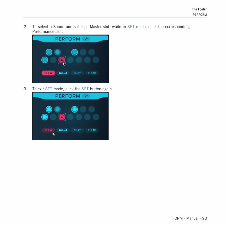
2. To select a Sound and set it as Master slot, while in SET mode, click the correspondingPerformance slot.
3. To exit SET mode, click the SET button again.
The Footer
PERFORM
FORM - Manual - 98

4. To play back the Master slot and its assigned slave voices, press any key on your MIDIkeyboard.
→ The Performance slots containing the playing voices illuminate, whereas the silent voicesremain unilluminated.
With Keyboard mode activated and the SET button engaged, you can also switch theMaster slot to another Performance slot by pressing any key in the control octave of yourMIDI keyboard.
Editing Slave Slots
Sometimes you may want to edit the settings of a Sound saved in a Slave slot. To do so with-out simultaneously setting it as Master slot, follow these steps:
1. Ensure that the SET button is not illuminated.
The Footer
PERFORM
FORM - Manual - 99

2. To open the Sound saved to one of the Slave slots, click the corresponding Perform-ance slot.
→ Editing FORM's parameters will automatically save the Sound to the Performance slot.
The amount of Slave slots available for editing are limited to the amount of voices set by theVoice Amount button in the Header. A setting of 2 means Master slot and one Slave slot, asetting of 3 means Master slot and two Slave slots, and a setting of 4 means Master slot andthree Slave slots.
6.4 Macro Controls
The four Macro controls are located at the bottom of the Footer; they are visible at all time.Any parameter that can be assigned as modulation destination cannot only be assigned to themodulators in the MODULATION section, but also to the Macro controls.
Macro controls
The Footer
Macro Controls
FORM - Manual - 100

6.4.1 Assigning Macro Controls to Modulation Destinations
Each FORM parameter that can be assigned as a modulation destination can also be assignedfor Macro control. Each parameter can be assigned to up to three modulators or Macro controlssimultaneously. Each knob in the Macro controls can be assigned to control an unlimitedamount of distinct parameters.
1. To open the modulation assignment menu, click the parameter label directly below theparameter.
The modulation assignment menu will open and display the three modulation slots for thechosen parameter.
The Footer
Macro Controls
FORM - Manual - 101

2. To select a modulation source, click one of the three modulation slots and the modula-tion source menu will open.
The Footer
Macro Controls
FORM - Manual - 102

3. To display the Macro controls, click the MACRO button.
The four Macro controls are listed as M1, M2, M3, and M4.
The Footer
Macro Controls
FORM - Manual - 103

4. To select one of the Macro controls, click the corresponding button.
The Footer
Macro Controls
FORM - Manual - 104

5. Set the amount of modulation that will be applied by clicking and dragging the modula-tion depth slider for the selected slot.
6.4.2 The Macro Label Menu
Each Macro control can be labeled via the MACRO LABEL menu, which lets you select one ofeight labels to organize your macros. By labeling your Macro controls, you can, for example,assign a set of effect controls to the same Macro control and then select the label FX from theMACRO LABEL menu. You will then be able to edit all the assigned effect controls simultane-ously by turning the Macro control labeled FX.
The Footer
Macro Controls
FORM - Manual - 105

1. To open the MACRO LABEL menu, click the label below the Macro control you want tolabel.
The Footer
Macro Controls
FORM - Manual - 106

2. To select the label, click the label name in the menu.
→ The selected label is displayed below the Macro control.
6.4.3 Knob Type and Polarity
All Macro controls can be used either as unipolar or bipolar knobs. When used as bipolar knobtypes, the controls that you have assigned to the Macro will move in either direction from theirset levels when you turn the Macro control. When used as unipolar knobs, the assigned con-trols will only move in the direction that you have assigned them to, using the modulation slid-er in the modulation menu that appears when you click a control's label.
The Footer
Macro Controls
FORM - Manual - 107

1. To open the KNOB TYPE menu, click the label below the Macro control you want to edit.
The Footer
Macro Controls
FORM - Manual - 108

2. To select polarity for the Macro control and all its assigned destinations, click either BI-POLAR or UNIPOLAR.
The Footer
Macro Controls
FORM - Manual - 109

→ Turning the Macro control now also moves all assigned destinations in accordance withthe set polarity.
The Footer
Macro Controls
FORM - Manual - 110

7 Credits
Product Design: Jonathan Heppner
Instrument Development: Alexander Potehkin, Dietrich Pank, Clement Destephan, JonathanHeppner
DSP Development: Mickael Le Goff, Francisco Garcia, Steinunn Arnardottir,
User Interface Design: Simon Martin
Quality Assurance: Tommaso De Donatis, Frank Ellendt, Daniel Ramm
Sound Design: Jamil Samad, Tommaso De Donatis, Antonio de Spirt, Jonathan Heppner, Die-trich Pank, Jeremiah Savage, Noritaka Ubukata, John Valasis, Ksenija Ladic, 9b0, Jeremy Jan-zen, Xenos Soundworks, Simon Stockhausen
Documentation: Gustav Sto. Tomas
Product Management: Marin Vrbica
Special thanks to: Eike Jonas, Efflam Le Bivic, Oleg Kharkov, James Walker Hall, and the RE-AKTOR team.
Credits
FORM - Manual - 111