Forced draught gas burners - Riello
80
Installation, use and maintenance instructions 20081760 (5) - 03/2018 Forced draught gas burners Modulating operation CODE MODEL TYPE 20074274 - 20074275 RS 310/EV MZ 1142T2 20074276 - 20074277 RS 410/EV MZ 1143T2 20074278 RS 510/EV MZ 1144T2 20074279 RS 610/EV MZ 1145T2 GB
-
Upload
khangminh22 -
Category
Documents
-
view
4 -
download
0
Transcript of Forced draught gas burners - Riello

Installation, use and maintenance instructions
20081760 (5) - 03/2018
Forced draught gas burners
Modulating operation
CODE MODEL TYPE
20074274 - 20074275 RS 310/EV MZ 1142T2
20074276 - 20074277 RS 410/EV MZ 1143T2
20074278 RS 510/EV MZ 1144T2
20074279 RS 610/EV MZ 1145T2
GB

Translation of the original instructions

1 20081760GB
Contents
1 Declarations................................................................................................................................................................................ 3
2 Information and general warnings............................................................................................................................................ 4
2.1 Information about the instruction manual .................................................................................................................... 42.1.1 Introduction.................................................................................................................................................................. 42.1.2 General dangers.......................................................................................................................................................... 42.1.3 Other symbols ............................................................................................................................................................. 42.1.4 Delivery of the system and the instruction manual...................................................................................................... 5
2.2 Guarantee and responsibility....................................................................................................................................... 5
3 Safety and prevention................................................................................................................................................................ 6
3.1 Introduction.................................................................................................................................................................. 6
3.2 Personnel training ....................................................................................................................................................... 6
4 Technical description of the burner ......................................................................................................................................... 7
4.1 Burner designation ...................................................................................................................................................... 7
4.2 Models available.......................................................................................................................................................... 8
4.3 Burner categories - Countries of destination ............................................................................................................... 8
4.4 Technical data ............................................................................................................................................................. 8
4.5 Electrical data.............................................................................................................................................................. 9
4.6 Burner weight .............................................................................................................................................................. 9
4.7 Maximum dimensions................................................................................................................................................ 10
4.8 Firing rates ................................................................................................................................................................ 11
4.9 Test boiler.................................................................................................................................................................. 12
4.10 Burner equipment...................................................................................................................................................... 12
4.11 Burner description ..................................................................................................................................................... 13
4.12 Electrical panel description........................................................................................................................................ 14
4.13 Control box for the air/fuel ratio (REC37...) ............................................................................................................... 15
4.14 Operation sequence of the burner............................................................................................................................. 174.14.1 List of phases ............................................................................................................................................................ 18
4.15 Operator panel operation .......................................................................................................................................... 184.15.1 Description of the symbols on the display ................................................................................................................. 184.15.2 Description of the buttons.......................................................................................................................................... 19
4.16 Servomotor (SQM33....) ............................................................................................................................................ 20
5 Installation ................................................................................................................................................................................ 21
5.1 Notes on safety for the installation ............................................................................................................................ 21
5.2 Handling .................................................................................................................................................................... 21
5.3 Preliminary checks .................................................................................................................................................... 21
5.4 Operating position ..................................................................................................................................................... 22
5.5 Preparing the boiler ................................................................................................................................................... 225.5.1 Boring the boiler plate ............................................................................................................................................... 225.5.2 Blast tube length........................................................................................................................................................ 22
5.6 Securing the burner to the boiler ............................................................................................................................... 22
5.7 Access to head internal part...................................................................................................................................... 23
5.8 Probe-electrode position ........................................................................................................................................... 23
5.9 Gas butterfly valve..................................................................................................................................................... 24
5.10 Combustion head adjustment.................................................................................................................................... 24
5.11 Gas pressures ........................................................................................................................................................... 265.11.1 Gas feeding line ........................................................................................................................................................ 265.11.2 Gas train.................................................................................................................................................................... 275.11.3 Gas train installation.................................................................................................................................................. 275.11.4 Gas pressure............................................................................................................................................................. 28
5.12 Electrical wiring ......................................................................................................................................................... 295.12.1 Supply cables and external connections passage .................................................................................................... 30

20081760 2 GB
Contents
6 Start-up, calibration and operation of the burner ..................................................................................................................31
6.1 Notes on safety for the first start-up...........................................................................................................................31
6.2 Adjustments prior to ignition.......................................................................................................................................31
6.3 Start-up procedure .....................................................................................................................................................31
6.4 Air / fuel adjustment ...................................................................................................................................................326.4.1 Air adjustment for maximum output ...........................................................................................................................326.4.2 Air/fuel adjustment and output modulation system ....................................................................................................326.4.3 Burner adjustment......................................................................................................................................................326.4.4 Output upon ignition...................................................................................................................................................326.4.5 Maximum output ........................................................................................................................................................326.4.6 Minimum output .........................................................................................................................................................32
6.5 Final adjustment of the pressure switches.................................................................................................................336.5.1 Air pressure switch.....................................................................................................................................................33
6.6 Pressure switch adjustment .......................................................................................................................................346.6.1 Maximum gas pressure switch...................................................................................................................................346.6.2 Minimum gas pressure switch....................................................................................................................................346.6.3 PVP pressure switch kit .............................................................................................................................................34
6.7 Visualisation and programming mode........................................................................................................................356.7.1 Normal mode .............................................................................................................................................................356.7.2 Info mode ...................................................................................................................................................................366.7.3 Service mode .............................................................................................................................................................376.7.4 Parameters Mode ......................................................................................................................................................37
6.8 Parameter modification procedure.............................................................................................................................386.8.1 Modify "acceleration- deceleration train" parameter ..................................................................................................406.8.2 Modify the parameter for continuous/intermittent operation (FS2/FS1) .....................................................................40
6.9 Start-up procedure .....................................................................................................................................................41
6.10 Backup / Restore procedure ......................................................................................................................................436.10.1 Backup .......................................................................................................................................................................436.10.2 Restore ......................................................................................................................................................................446.10.3 List of parameters ......................................................................................................................................................46
6.11 Operation ...................................................................................................................................................................50
6.12 Ignition failure.............................................................................................................................................................50
6.13 Burner flame goes out during operation.....................................................................................................................51
6.14 Stopping of the burner ...............................................................................................................................................51
6.15 Final checks (with burner operating) ..........................................................................................................................51
7 Maintenance ..............................................................................................................................................................................52
7.1 Notes on safety for the maintenance .........................................................................................................................52
7.2 Maintenance programme ...........................................................................................................................................527.2.1 Maintenance frequency..............................................................................................................................................527.2.2 Safety test - with gas ball valve closed ......................................................................................................................527.2.3 Checking and cleaning...............................................................................................................................................527.2.4 Safety components ....................................................................................................................................................537.2.5 Measuring the ionisation current ................................................................................................................................547.2.6 Checking the air and gas pressure on the combustion head.....................................................................................54
7.3 Checking the position of the rpm sensor....................................................................................................................54
7.4 Opening the burner ....................................................................................................................................................54
7.5 Closing the burner......................................................................................................................................................55
8 Faults - Possible causes - Solutions.......................................................................................................................................56
8.1 List of error codes ......................................................................................................................................................56
A Appendix - Accessories ...........................................................................................................................................................65
B Appendix - Electrical panel layout...........................................................................................................................................67

3 20081760GB
Declarations
1 Declarations
Declaration of Conformity in accordance with ISO / IEC 17050-1
Manufacturer: RIELLO S.p.A.
Address: Via Pilade Riello, 737045 Legnago (VR)
Product: Forced draught gas burners
Model and type: RS 310/EV MZRS 410/EV MZRS 510/EV MZRS 610/EV MZ
1142T21143T21144T21145T2
These products are in compliance with the following Technical Standards:
EN 676
EN 12100
and according to the European Directives:
GAD 2009/142/EC Gas Devices Directive
MD 2006/42/EC Machine Directive
LVD 2014/35/UE Low Voltage Directive
EMC 2014/30/UE Electromagnetic Compatibility
The products are marked as follows:
RS 310/EV MZ (Class 2 EN 676)RS 410/EV MZ (Class 2 EN 676)RS 510/EV MZ (Class 2 EN 676)RS 610/EV MZ (Class 2 EN 676)
The quality is guaranteed by a quality and management system certified in accordance with UNI EN ISO 9001.
Manufacturer's Declaration
RIELLO S.p.A. declares that the following products comply with the NOx emission limits specified by German standard “1. BImSchV revision 26.01.2010”.
Product Model Type Output
Forced draught gas burners RS 310/EV MZ 1142T2 600 - 3900 kWRS 410/EV MZ 1143T2 800 - 4900 kWRS 510/EV MZ 1144T2 802 - 5520 kWRS 610/EV MZ 1145T2 820 - 6300 kW
Legnago, 21.05.2015 Executive General ManagerRIELLO S.p.A. - Burner Department
Research & Development DirectorRIELLO S.p.A. - Burner Department
Mr. U. Ferretti Mr. F. Comencini
CE-0085CP0166

20081760 4 GB
Information and general warnings
2.1 Information about the instruction manual
2.1.1 Introduction
The instruction manual supplied with the burner: is an integral and essential part of the product and must not
be separated from it; it must therefore be kept carefully forany necessary consultation and must accompany the burnereven if it is transferred to another owner or user, or toanother system. If the manual is lost or damaged, anothercopy must be requested from the Technical Assistance Ser-vice of the area;
is designed for use by qualified personnel; offers important indications and instructions relating to the
installation safety, start-up, use and maintenance of theburner.
Symbols used in the manual
In some parts of the manual you will see triangular DANGERsigns. Pay great attention to these, as they indicate a situation ofpotential danger.
2.1.2 General dangers
The dangers can be of 3 levels, as indicated below.
2.1.3 Other symbols
Abbreviations used
Ch. ChapterFig. FigurePage PageSec. SectionTab. Table
2 Information and general warnings
DANGER
Maximum danger level!This symbol indicates operations which, if not car-ried out correctly, cause serious injury, death orlong-term health risks.
WARNING
This symbol indicates operations which, if not car-ried out correctly, may cause serious injury, deathor long-term health risks.
CAUTION
This symbol indicates operations which, if not car-ried out correctly, may cause damage to the ma-chine and/or injury to people.
DANGER
DANGER: LIVE COMPONENTS
This symbol indicates operations which, if not car-ried out correctly, lead to electric shocks with le-thal consequences.
DANGER: FLAMMABLE MATERIAL
This symbol indicates the presence of flammablematerials.
DANGER: BURNING
This symbol indicates the risks of burns due tohigh temperatures.
DANGER: CRUSHING OF LIMBS
This symbol indicates the presence of movingparts: danger of crushing of limbs.
WARNING: MOVING PARTS
This symbol indicates that you must keep limbsaway from moving mechanical parts; danger ofcrushing.
DANGER: EXPLOSION
This symbol signals places where an explosive at-mosphere may be present. An explosive atmos-phere is defined as a mixture - under atmosphericconditions - of air and flammable substances inthe form of gases, vapours, mist or dust in which,after ignition has occurred, combustion spreads tothe entire unburned mixture.
PERSONAL PROTECTION EQUIPMENT
These symbols indicate the equipment that mustbe worn and kept by the operator for protectionagainst threats against safety and/or health whileat work.
OBLIGATION TO ASSEMBLE THE COVERAND ALL THE SAFETY AND PROTECTION DE-VICES
This symbol signals the obligation to reassemblethe cover and all the safety and protection devicesof the burner after any maintenance, cleaning orchecking operations.
ENVIRONMENTAL PROTECTION
This symbol gives indications for the use of themachine with respect for the environment.
IMPORTANT INFORMATION
This symbol indicates important information thatyou must bear in mind.
IMPORTANT
This symbol indicates important information thatyou must bear in mind.
This symbol indicates a list.

5 20081760GB
Information and general warnings
2.1.4 Delivery of the system and the instruction manual
When the system is delivered, it is important that: the instruction manual is delivered to the user by the system
manufacturer, with the recommendation to keep it in theroom where the heat generator is to be installed.
The instruction manual shows:– the serial number of the burner;
– the address and telephone number of the nearest Assis-tance Centre
The system supplier must carefully inform the user about:– the use of the system; – any further tests that may be required before activating the
system; – maintenance, and the need to have the system checked at
least once a year by a representative of the manufactureror another specialised technician.To ensure a periodic check, the manufacturer recom-mends the drawing up of a Maintenance Contract.
2.2 Guarantee and responsibility
The manufacturer guarantees its new products from the date ofinstallation, in accordance with the regulations in force and/or thesales contract. At the moment of the first start-up, check that theburner is integral and complete.
In particular, the rights to the guarantee and the responsibility willno longer be valid, in the event of damage to things or injury topeople, if such damage/injury was due to any of the followingcauses: incorrect installation, start-up, use and maintenance of the
burner; improper, incorrect or unreasonable use of the burner; intervention of unqualified personnel; carrying out of unauthorised modifications on the equipment; use of the burner with safety devices that are faulty, incor-
rectly applied and/or not working; installation of untested supplementary components on the
burner; powering of the burner with unsuitable fuels; faults in the fuel supply system; continuation of use of the burner when a fault has occurred; repairs and/or overhauls incorrectly carried out; modification of the combustion chamber with inserts that
prevent the regular development of the structurally estab-lished flame;
insufficient and inappropriate surveillance and care of thoseburner components most likely to be subject to wear andtear;
use of non-original components, including spare parts, kits,accessories and optional;
force majeure.
The manufacturer furthermore declines any and every re-sponsibility for the failure to observe the contents of thismanual.
.........................................................................................
.........................................................................................
.........................................................................................
.........................................................................................
WARNING
Failure to observe the information given in thismanual, operating negligence, incorrect installa-tion and carrying out of non authorised modifica-tions will result in the annulment by themanufacturer of the guarantee that it supplies withthe burner.

20081760 6 GB
Safety and prevention
3.1 Introduction
The burners have been designed and built in compliance withcurrent regulations and directives, applying the known technicalrules of safety and envisaging all the potential danger situations.
It is necessary, however, to bear in mind that the imprudent andclumsy use of the equipment may lead to situations of death riskfor the user or third parties, as well as the damaging of the burneror other items. Inattention, thoughtlessness and excessive confi-dence often cause accidents; the same applies to tiredness andsleepiness.
It is a good idea to remember the following: The burner must only be used as expressly described. Any
other use should be considered improper and therefore dan-gerous.
In particular:
it can be applied to boilers operating with water, steam, diather-mic oil, and to other uses expressly foreseen by the manufactur-er;
the type and pressure of the fuel, the voltage and frequency of theelectrical power supply, the minimum and maximum deliveries forwhich the burner has been regulated, the pressurisation of thecombustion chamber, the dimensions of the combustion cham-ber and the room temperature must all be within the values indi-cated in the instruction manual. Modification of the burner to alter its performance and desti-
nations is not allowed. The burner must be used in exemplary technical safety con-
ditions. Any disturbances that could compromise safety mustbe quickly eliminated.
Opening or tampering with the burner components is notallowed, apart from the parts requiring maintenance.
Only those parts envisaged by the manufacturer can bereplaced.
3.2 Personnel training
The user is the person, body or company that has acquired themachine and intends to use it for the specific purpose. He is re-sponsible for the machine and for the training of the people work-ing around it.
The user: undertakes to entrust the machine exclusively to suitably
trained and qualified personnel; undertakes to inform his personnel in a suitable way about
the application and observance of the safety instructions.With that aim, the user undertakes to ensure that everyoneknows the use and safety instructions for his own duties;
Personnel must follow all the danger and caution indicationsshown on the machine.
Personnel must not carry out, on their own initiative, opera-tions or interventions that are not within their province.
Personnel are obliged to inform their superiors of everyproblem or dangerous situation that may arise.
The assembly of parts of other makes, or any modifications,can alter the characteristics of the machine and hence com-promise operating safety. The manufacturing companytherefore accepts no responsibility whatsoever for any whichmay result from the use of non-original parts.
In addition:
3 Safety and prevention
WARNING
The manufacturer guarantees safety and properfunctioning only if all burner components are intactand positioned correctly.
must take all the measures necessary to pre-vent unauthorised people gaining access tothe machine;
the user must inform the manufacturer iffaults or malfunctioning of the accident pre-vention systems are noticed, along with anypresumed danger situation;
personnel must always use the personal pro-tective equipment envisaged by legislationand follow the indications given in this man-ual.

7 20081760GB
Technical description of the burner
4.1 Burner designation
4 Technical description of the burner
Range: R
Size
Fuel: Natural gas
Gas oil
Gas oil / Methane
Adjustment :
Flame control system :FS1
FS2
Standard (1 stop every 24 h)
Continuous working (1 stop every 72 h)
Electrical supply of the system :3/400/50
3/230/50
Voltage of auxiliaries :230/50/60
110/50/60
R S 310 EV TC 3/400/50 230/50/60
BASIC DESIGNATION
EXTENDED DESIGNATION
MZ
3N / 400V / 50Hz
3 / 230V / 50Hz
230V / 50-60Hz
110V / 50-60Hz
Heavy oil
E Electronic cam
EV Electronic cam with variable speed (with Inverter)
P Proportional air/gas valve
BP Two stage (light oil) / Proportional valve (gas)
M Mechanical cam
S
L
LS
N
Head : TC Standard headTL Long head
Emission: C01 - ...C02 - MZ
C03 - BLU
C03 - MX
Class 1 EN676Class 2 EN676
Class 3 EN676
Class 3 EN676
FS1/FS2*
WARNING
*The burner leaves the factory set up for FS1 op-eration. If FS2 operation is required, see section“Modify the parameter for continuous/intermittentoperation (FS2/FS1)” on page 40.

20081760 8 GB
Technical description of the burner
4.2 Models available
Tab. A
4.3 Burner categories - Countries of destination
Tab. B
4.4 Technical data
Tab. C(1) Reference conditions: Ambient temperature 20°C - Gas temperature 15°C - Barometric pressure 1013 mbar - Altitude 0 m a.s.l.
(2) Pressure at the test point of the pressure switch 5)(Fig. 5) with zero pressure in the combustion chamber and at maximum burner output.
(3) Sound pressure measured in manufacturer's combustion laboratory, with burner operating on test boiler and at maximum rated output. The soundpower is evaluated, in line with the regulations, on a spherical surface centred on the burner and with a radius of 1 metre.
Designation Voltage Start-up Code
RS 310/EV MZ FS1/FS23/230/50 Inverter 20074274
3/400/50 Inverter 20074275
RS 410/EV MZ FS1/FS23/230/50 Inverter 20074276
3/400/50 Inverter 20074277
RS 510/EV MZ FS1/FS2 3/400/50 Inverter 20074278
RS 610/EV MZ FS1/FS2 3/400/50 Inverter 20074279
Gas category Destination countryI2H SE - FI - AT - GR - DK - ES - GB - IT - IE - PT - IS - CH - NO
I2ELL DE
I2E - I2 (43,46 ÷ 45,3 MJ/m3 (0°C)) NL
I2Er FR
I2E(R)B BE
I2E LU - PL
Model RS 310/EV MZ RS 410/EV MZ RS 510/EV MZ RS 610/EV MZ
Type (FS1/FS2*) 1142T2 1143T2 1144T2 1145T2
Power(1)Delivery (1)
min - max kW 600/1300 - 3900 800/2000 - 4900 802/2200 - 5520 820/2400 - 6300
Fuels Natural gas: G20 (methane gas) - G21 - G22 - G23 - G25
Gas pressure at max. output (2)Gas: G20/G25
mbar 33,2/49,5 41,6/62 48,9/73 64,6/96,4
OperationFS1: Intermittent (min. 1 stop in 24 hours)
FS2: Continuous (min. 1 stop in 72 hours)
Standard applications Boilers: water, steam, diathermic oil
Ambient temperature °C 0 - 50
Combustion air temperature °C max 60
Noise levels (3) Sound pressureSound power
dB(A)7889
8091
82.593,5
8596
9 20081760GB
Technical description of the burner
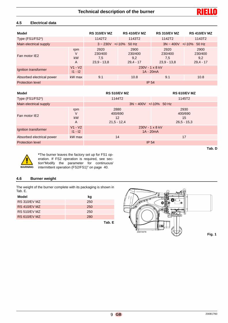
4.5 Electrical data
Tab. D
4.6 Burner weight
The weight of the burner complete with its packaging is shown inTab. E.
Tab. E
Model RS 310/EV MZ RS 410/EV MZ RS 310/EV MZ RS 410/EV MZ
Type (FS1/FS2*) 1142T2 1143T2 1142T2 1143T2
Main electrical supply 3 ~ 230V +/-10% 50 Hz 3N ~ 400V +/-10% 50 Hz
Fan motor IE2
rpmV
kWA
2920230/400
7,523,9 - 13,8
2900230/400
9,229,4 - 17
2920230/400
7,523,9 - 13,8
2900230/400
9,229,4 - 17
Ignition transformerV1 - V2I1 - I2
230V - 1 x 8 kV1A - 20mA
Absorbed electrical power kW max 9.1 10.8 9.1 10.8
Protection level IP 54
Model RS 510/EV MZ RS 610/EV MZ
Type (FS1/FS2*) 1144T2 1145T2
Main electrical supply 3N ~ 400V +/-10% 50 Hz
Fan motor IE2
rpmV
kWA
2880400/690
1221,5 - 12,4
2930400/690
1526,5 - 15,3
Ignition transformerV1 - V2I1 - I2
230V - 1 x 8 kV1A - 20mA
Absorbed electrical power kW max 14 17
Protection level IP 54
WARNING
*The burner leaves the factory set up for FS1 op-eration. If FS2 operation is required, see sec-tion“Modify the parameter for continuous/intermittent operation (FS2/FS1)” on page 40.
Model kg
RS 310/EV MZ 250
RS 410/EV MZ 250
RS 510/EV MZ 250
RS 610/EV MZ 280
Fig. 120072079

20081760 10 GB
Technical description of the burner
4.7 Maximum dimensions
The maximum dimensions of the burner are given in Fig. 2.
Bear in mind that inspection of the combustion head requires theburner to be opened and the rear part turned on the hinge.
The maximum dimensions of the open burner are indicated bythe L and R positions.
The l position is reference for the refractory thickness of the boilerdoor.
Tab. F
** Maximum position for the extraction of the servomotor cover.
WARNING
* The gas adaptor is set also for DN 80 bore.
Fig. 2
20072082
mm A B C D E F* G H I** L M N O R
RS 310/EV MZ 1178 519 178 306 520 DN65 900 790 177 1015 400 528 290 890
RS 410/EV MZ 1178 519 178 306 520 DN65 940 790 177 1015 400 528 290 890
RS 510/EV MZ 1178 519 178 306 520 DN65 940 790 177 1015 400 528 290 890
RS 610/EV MZ 1178 500 178 330 520 DN65 980 790 177 1015 400 528 290 890

11 20081760GB
Technical description of the burner
4.8 Firing rates
The MAXIMUM OUTPUT is chosen from within the diagram area(Fig. 3).
The MINIMUM OUTPUT must not be lower than the minimumlimit of the diagram:
Tab. G
Model kW
RS 310/EV MZ 600
RS 410/EV MZ 800
RS 510/EV MZ 800
RS 610/EV MZ 820
WARNING
The firing rate value (Fig. 3) has been obtainedconsidering an ambient temperature of 20 °C, anatmospheric pressure of 1013 mbar (approx. 0 ma.s.l.), and with the combustion head adjusted asshown on pag. 24.
Fig. 3Thermal power – kW
Pre
ssu
re in
co
mbu
stio
n he
ad -
mb
ar
20072010
RS 310/EV
RS 410/EV
RS 510/EV
RS 610/EV

20081760 12 GB
Technical description of the burner
4.9 Test boiler
The burner/boiler combination does not pose any problems if theboiler is EC approved and its combustion chamber dimensionsare similar to those indicated in the diagram (Fig. 4).
If the burner must be combined with a boiler that has not been ECapproved and/or its combustion chamber dimensions are clearlysmaller than those indicated in the diagram, consult the manufac-turer.
The firing rates were set in relation to special test boilers, accord-ing to EN 676 regulations.
In Fig. 4 you can see the diameter and length of the test combus-tion chamber.
Example: RS 510/EV MZOutput 7000 kW - diameter 120 cm - length 6m
4.10 Burner equipment
Gasket for gas train adaptor. . . . . . . . . . . . . . . . . . . . . . . . No. 1
Adaptor for gas train. . . . . . . . . . . . . . . . . . . . . . . . . . . . . . No. 1
Screws for fixing the gas train adaptor: M 16 x 70 . . . . . . No. 4
Thermal insulation screen . . . . . . . . . . . . . . . . . . . . . . . . . No. 1
M 18 x 60 screws to secure the burner flange to the boiler . . . . . . . . . . . . . . . . . . . . . . . . . . . . . . . . . . . . . . . . . No. 4
Cable grommets kit for optional electrical wiring input . . . . No. 1
M16 nuts to fix the gas elbow to the pipe coupling . . . . . . No. 8
Stud bolts M16X60 to fix the gas elbow to the pipe coupling . . . . . . . . . . . . . . . . . . . . . . . . . . . . . . . . . . . . . . . No. 1
Instructions . . . . . . . . . . . . . . . . . . . . . . . . . . . . . . . . . . . . No. 1
Spare parts list . . . . . . . . . . . . . . . . . . . . . . . . . . . . . . . . . No. 1
20057548 Fig. 4
Com
bus
tion
cham
ber
m

13 20081760GB
Technical description of the burner
4.11 Burner description
1 Lifting rings2 Fan3 Fan motor4 Air damper servomotor5 Combustion head gas pressure test point6 Combustion head7 Ignition electrode8 Flame stability disk9 Electrical panel casing10 Gas butterfly valve servomotor11 Fan air inlet12 Pipe coupling13 Gasket for boiler fixing14 Gas butterfly valve15 Shutter16 Combustion head movement screw17 Lever for controlling the dampers with graduated scale18 Air pressure switch19 Combustion head air pressure test point20 Maximum gas pressure switch with pressure test point21 Flame sensor probe22 Hinge for opening the burner23 Pressure test point for air pressure switch “+”24 Combustion head air pressure test points25 Gas train adapter26 Indication for checking the rotation direction of the purging
motor27 Flame inspection window28 Provision for flame sensor kit29 Reset button30 Transparent protection31 Rpm sensor
156191 16271189
17 11 4
20
14
8
29
30
217
25
22 282412513
10
26
3
2
23
31
20082864
Fig. 5
ASSEMBLY VIEW
The burner can be opened to the right or to the leftwithout links to the fuel supply side.
WARNING
To open the burner see section “Access to headinternal part” on page 23.

20081760 14 GB
Technical description of the burner
4.12 Electrical panel description
1 Electrical control box2 ON/OFF selector3 Output regulator4 Earth terminal5 Supply cables and external connections passage. See sec-
tion “Electrical wiring” on page 296 Bracket for applying the kits7 Main terminal supply board8 Relay with clean contacts for signalling the burner is in lock-
out9 Relay with clean contacts for signalling the burner is operat-
ing10 Auxiliary circuits fuse (includes a spare fuse)11 Air pressure switch12 Ignition transformer13 Ionisation probe cable14 Operator panel with LCD display15 Light signalling burner lockout16 Reset button17 Relay with clean contacts for VSD signal18 Relay with clean contacts19 Control terminal board 4-20 mA
12
14
6
2
5
4
4
134
4
5
7
4
3
16
15
1
11
919
18
17810
Fig. 6
20081976

15 20081760GB
Technical description of the burner
4.13 Control box for the air/fuel ratio (REC37...)
Warnings
The control box is a system to check the burners, based on a mi-croprocessor and equipped with components to adjust and su-pervise medium and large capacity forced draught burners.The control box contains the following components:– burner management system with valve leak detection control
device;– electronic device to check the fuel/air ratio with a maximum
of 2 actuators;– Modbus interface.
All interventions (assembly and installation operations,assistance, etc.) must be carried out by qualified personnel.
Before carrying out any checks on the wiring, fully isolate thesystem from the electric mains (omnipolar separation).Check the system is not powered and cannot be accidentallyreconnected. Failure to do this will lead to the risk of electro-cution.
Protection against electrocution from the control box and allconnected electric components is obtained with the correctassembly.
After every intervention (assembly and installation opera-tions, assistance, etc.), ensure the wiring is in order and thatthe parameters are correctly set, then perform the safetychecks.
Falls and collisions can negatively affect the safety func-tions. In this case, the control box must not be operated,even if it displays no evident damage.
During the programming of the air-fuel ratio control curves,the technician should constantly observe the quality of thecombustion process (for example using a gas analyser) and,in the event of inadequate combustion values or dangerousconditions, should take appropriate action, for example shut-ting down the system manually.
The plugs of the connection cables or other accessories canbe disconnected when the system has been switched off.
The connections to the actuators do not provide a secureseparation from the mains voltage. Before connecting orchanging the actuators the system should be off to avoid anyconditions that could cause the formation of condensation orhumidity. Otherwise, before switching on again, make surethat the entire control box is perfectly dry!
Static charges must be avoided since they can damage thecontrol box’s electronic components when touched.
Static charges must be avoided since they can damage thecontrol box’s electronic components when touched.
WARNING
To avoid accidents, material and/or environmentaldamage, observe the following instructions!
The control box is a safety device! Avoid openingor modifying it, or forcing its operation. RielloS.p.A. cannot assume any responsibility for dam-age resulting from unauthorised interventions!
Risk of explosion!
An incorrect configuration can provoke fuel over-charging, with the consequential risk of explosion!The operators must be aware that the incorrectsetting of the visualisation and operation controlbox, and of the positions of the fuel and/or air ac-tuators, can cause dangerous conditions duringburner operation.
WARNING
For the safety and reliability of the control box,comply with the following instructions:
Fig. 7D8266

20081760 16 GB
Technical description of the burner
Technical data
Tab. H
Control box Mains voltage AC 230 V -15% / +10%
Mains frequency 50 / 60 Hz ±6%
Power absorption < 30 W
Safety class I, with components in compliance with II and III, ac-cording to DIN EN 60730-1
Load on‘input’ terminals
Fuse on the control box (can be inspected) 6.3 AT
Undervoltage– Safety switch-off from operating position to mains
voltage– Restart when mains voltage picks up
< AC 186V
> AC 195V
Cable length – Main line AC 230 V– Control load (TL1-TL2)– External reset button (RS)– Load exit (DC 0/2...10V)– Fuel valve – Other lines
Max. 100 m (100 pF / m)Max. 20 m (100 pF/m)Max 20 m (100 pF/m)Max. 10 m (100 pF/m)Max. 3 m (100 pF/m)Max. 3 m (100 pF/m)
Environmental conditions
Storage– Climatic conditions– Mechanical conditions– Temperature range– Humidity
DIN EN 60721-3-1Class 1K3Class 1M2-20 ... +60 °C< 95% RH
Transport– Climatic conditions– Mechanical conditions– Temperature range– Humidity
DIN EN 60721-3-2Class 2K2Class 2M2-30 ... +60 °C< 95% RH
Operation– Climatic conditions– Mechanical conditions– Temperature range– Humidity
DIN EN 60721-3-3Class 3K3Class 3M3-20 ... +60 °C< 95% RH
WARNING
Condensation, the formation of ice and the entryof water are prohibited!

17 20081760GB
Technical description of the burner
4.14 Operation sequence of the burner
t1
p
P
P
5 s 30 s
P
P
00 02 10 12 22 24 30 36 38 39 40 42
8)
44 6260 70 72 74 78 80 81 82 83 90
246245244243242248234233
212
230
0,6 s
227
229
244226230
6) 13)5)27 s
214213
217 211
4)
9) 9)
2)
12)
7) 7) 7)
3)
Phase number
Thermostat/pressure switch
OU
TP
UT
SIG
NA
LS
Thermostat/pressure switch
Ionisation probe ION
Air pressure switch PA
Min. gas pressure switch
Min. gas pressure switch
Gas pressure switch for PGVP leak detection control
Alternative to the control
safety TS
Fan motor MV
Transformer of
Safety valve VS
Fuel valve V1
Fuel valve V2
Pilot valve VP
Lock-out signal
indicator TL
SE
RV
OM
OT
OR
S
Air
Fu
el
90°Nominal load
Pos. of post-purgingIgnition load
Low flamePos. without load
0°
S9024
Fig. 8
Checking ofseal
Switching offStart-up
Timer 1 (parameters)
Timer 2 (parameters)
Timer 3 = max. phase time
Input signals
PGmin
PGMin
Max gas pressure switchPGMax
CPI seal
TA ignition
90°Nominal load
Pos. of post-purgingIgnition load
Low flamePos. without load
0°
RAST plug
X3-04 Pin 1/2
PIN number
X5-03 Pin 1/4
X10-05
X3-02 Pin 1/2
X5-01 Pin 2/3
X5-01 Pin 2/3
X5-02 Pin 2/3
X9-04 Pin 2/3
X5-02 Pin 2/3
X3-05 Pin 1
X4-02 Pin 2/3
X6-03 Pin 2/3
X8-02 Pin 1/3
X7-01 Pin 2/3
X7-02 Pin 2/3
X3-05 Pin 2
RAST plugPIN number
X54
X53
Signal ON
Signal OFF
Both states are allowed
X74
VS
D
Operation
Timer - Resolution - Ratio
INP
UT
SIG
NA
LS
Pin 2 Pin 3/4X10-06 Pin 1/2
90°Nominal load
Pos. of post-purgingIgnition load
Low flamePos. without load
0°

20081760 18 GB
Technical description of the burner
4.14.1 List of phases
4.15 Operator panel operation
The REC37 ... control box is directly connected to the operatorpanel (Fig. 9).
The buttons allow you to programme the operation and diagnos-tics menus.
The burner management system is shown on the LCD display(Fig. 10). To simplify the diagnostics, the display shows the oper-ating status, type of problem, and when the problem arose.
4.15.1 Description of the symbols on the display
The brightness of the display can be adjusted from 0 ... 100%with the parameter 126.
Phase Description
Ph00 Lockout phase
Ph02 Safety phase
Ph10 Closing paused
Ph12 Standby
Ph22 Fan motor (MV) = ON Safety valve (VS) = ON
Ph24 The burner moves to the pre-purging position
Ph30 Pre-purging time
Ph36 The burner moves to the ignition position
Ph38 Ignition phase (TA) = ON
Ph39 Minimum gas pressure switch test (PGmin.)
Ph40 Fuel valve (V) = ON
Ph42 Ignition (TA) = OFF
Ph44 t44 = interval time 1
Ph60 Operation
Ph62 The burner moves to the switching off position
Ph70 t13 = post-combustion time
Ph72 The burner moves to the post-purging position
Ph74 t8 = post-purging time
Ph78 t3 = post-purging time
Ph80 emptying time (valve leak detection)
Ph81 Atmospheric time test (valve leak control)
Ph82 filling time (valve leak detection)
Ph83 pressure test time (valve leak detection)
Ph90 Standby time due to lack of gas
Phase Description
WARNING
Observe the procedures and adjustmentsshown below.
All interventions (assembly and installationoperations, assistance, etc.) must be carriedout by qualified personnel.
If the display and operator panel are dirty,clean them with a dry cloth.
Protect the panel from excessive tempera-tures and liquids.
D9001Fig. 9
Lock-out lamp
Flame presence
Valve poweredIgnition transformer
Fan motor powered
Pre-heater active
Heat request
Info mode active
Service mode active
Closure of servomotors
Opening of servomotors
Unit of measurement
Lockout
Parameter mode active
only for light oil burners
V h min sD9000
powered
Fig. 10

19 20081760GB
Technical description of the burner
4.15.2 Description of the buttons
Tab. I
Button Button Function
Button FTo adjust the fuel servomotor
(keep pressed and adjust the value by pressing or )
Button ATo adjust the air servomotor
(keep pressed and adjust the value by pressing or )
Buttons A and FVSD function
To change the mode setting parameter P
(simultaneously press and plus or
Button Info and Enter
• Enter in Parameters Mode• Reset in the event of a lockout• Access to a lower level of the menu• To navigate in Mode Info or Service and permits:
– the selection of the parameter (flashing symbol) (press for <1 s)– access to a lower level of the menu (press from 1...3 s)– access to a higher level of the menu (press from 3...8 s)– access to another Mode (press for > 8 s)
Button -
Lowering the value– Access to a lower point of the modulation curve– Scrolling the parameter list
Button +
Increasing the value– Access to a higher point of the modulation curve– Scrolling the parameter list
Buttons - and +
Quit function (ESC)
(press and simultaneously)– Does not confirm the value– Access to a higher level of the menu
F F
A A
VSD
AFF A
������
ESC

20081760 20 GB
Technical description of the burner
4.16 Servomotor (SQM33....)
Warnings
Installation notes The static torque is reduced when the electrical supply of the
actuator is switched off.
Technical data
Tab. J
WARNING
To avoid accidents, material or environmentaldamage, observe the following instructions!Do not open, modify or force the actuators.
All interventions (assembly and installationoperations, assistance, etc.) must be carriedout by qualified personnel.
Before modifying the wiring of the servomotorin the connection area, fully disconnect theburner control device from the power supply(omnipolar separation).
To avoid the risk of electrocution, protect theconnection terminals in a suitable mannerand correctly fix the cover.
After every intervention (assembly and instal-lation operations, assistance, etc.), ensurethe wiring is in order, then make the safetychecks.
Falls and collisions can negatively affect thesafety functions. In this case, the servomotormust not be operated, even if it displays noevident damage.
WARNING
Assembly notes
The connection between the actuator commandshaft and the control element must be rigid, with-out any mechanical play.
WARNING
During the maintenance or replacement of theactuators, be careful not to invert the connec-tors.
Model SQM33.5...
Operating voltage AC / DC 24V ± 20%
Safety class 2 according to EN 60 730
Power absorption Max. 10 W
Protection level IP54 in compliance with EN 60 529-1
Cable connection RAST2,5, connectors
Rotation direction - GAS servomotor: clockwise - Air servomotor: anticlockwise
WARNING
The rotation direction is set in thefactory using the control box param-eter REC ...
Rated torque (max.) 3 Nm
Static torque (max.) 3 Nm
Running time (min.) for 90°
5....120 s.
Weight approx. 1.4 kg
Environmental conditions:
OperationClimatic conditionsMechanical conditionsTemperature rangeHumidity
DIN EN 60 721-3-3Class 3K5Class 3M4-20...+60°C< 95% rh
WARNING
Condensation, the formation of ice and the entryof water are prohibited!
D8271 Fig. 11

21 20081760GB
Installation
5.1 Notes on safety for the installation
After carefully cleaning all around the area where the burner is tobe installed, and arranging for the environment to be illuminatedcorrectly, proceed with the installation operations.
5.2 Handling
The burner packaging includes a wooden platform, it is thereforepossible to move the burner (still packaged) with a transpallettruck or fork lift truck.
5.3 Preliminary checks
Checking the consignment
Checking the characteristics of the burner
Check the identification label of the burner, showing: the model (A)(Fig. 12) and type of burner (B); the year of manufacture, in cryptographic form (C); the serial number (D); the data for electrical supply and the protection level (E); the absorbed electrical power (F); the types of gas used and the relative supply pressures (G); the data of the burner's minimum and maximum output pos-
sibilities (H) (see Firing rate)Warning. The burner output must be within the boiler's firingrate;
the category of the appliance/countries of destination (I).
5 Installation
DANGER
All the installation, maintenance and disassemblyoperations must be carried out with the electricitysupply disconnected.
WARNING
The installation of the burner must be carried outby qualified personnel, as indicated in this manualand in compliance with the standards and regula-tions of the laws in force.
DANGER
Combustion air inside the boiler must be free fromhazardous mixes (e.g.: chloride, fluoride, halo-gen); if present, it is highly recommended to carryout cleaning and maintenance more frequently.
WARNING
The handling operations for the burner can behighly dangerous if not carried out with the great-est attention: keep any unauthorised people at adistance; check the integrity and suitableness ofthe available means of handling.Check also that the area in which you are workingis empty and that there is an adequate escapearea (i.e. a free, safe area to which you can quick-ly move if the burner should fall).When handling, keep the load at not more than20-25 cm from the ground.
After positioning the burner near the installationpoint, correctly dispose of all residual packaging,separating the various types of material.
CAUTION
Before proceeding with the installation operations,carefully clean all around the area where the burn-er will be installed.
CAUTION
After removing all the packaging, check the integ-rity of the contents. In the event of doubt, do notuse the burner; contact the supplier.
The packaging elements (wooden cage or card-board box, nails, clips, plastic bags, etc.) must notbe abandoned as they are potential sources ofdanger and pollution; but should be collected anddisposed of in the appropriate places.
WARNING
A burner label, or any other component, that hasbeen tampered with, removed or is missing, pre-vents the definite identification of the burner andmakes any installation or maintenance work diffi-cult
R.B.L.
GAS-KAASUGAZ-AEPIO
X
RIELLO S.p.A.I-37045 Legnago (VR)
AD E
B CF
I
G HG H
Fig. 12D10411

20081760 22 GB
Installation
5.4 Operating position
5.5 Preparing the boiler
5.5.1 Boring the boiler plate
Drill the combustion chamber locking plate as shown in Fig. 14(Tab. K). The position of the threaded holes can be marked usingthe thermal screen supplied with the burner.
5.5.2 Blast tube length
The length of the blast tube must be selected according to the in-dications provided by the manufacturer of the boiler, and in anycase it must be greater than the thickness of the boiler door com-plete with its fettling.For boilers with front flue passes 1)(Fig. 15) or flame inversionchamber, a protection in refractory material 5) must be insertedbetween the boiler fettling 2) and the blast tube 4).The refractory can have a conical shape (minimum 60°).This protective fettling must not compromise the extraction of theblast tube.For boilers with a water-cooled front piece, a refractory lining 2)-5) (Fig. 15) is not necessary, unless expressly requested by theboiler manufacturer. Tab. K
5.6 Securing the burner to the boiler
Fit the heat insulation supplied onto the blast tube(4)(Fig. 15).
Fit the entire burner onto the boiler hole prepared previously(Fig. 14), and fasten with the screws supplied.
WARNING
The burner is designed to operate only inpositions 1, 2, 3 and 4 (Fig. 13).
Installation 1 is preferable, as it is the onlyone that allows the maintenance operationsas described in this manual.
Installations 2, 3 and 4 permit operation butmake maintenance and inspection of thecombustion head more difficult.
DANGER
Any other position could compromise the cor-rect operation of the appliance.
Installation 5 is prohibited for safety reasons.
Fig. 13
2 3 4 51
D7739
mm A B C
RS 310/EV MZ 335 452 M18
RS 410/EV MZ 335 452 M18
RS 510/EV MZ 335 452 M18
RS 610/EV MZ 350 452 M18
Fig. 14D455
Prepare a suitable lifting system using the rings3)(Fig. 15), after removing the fixing screws 7) ofthe casing 8).
WARNING
The seal between burner and boiler must beairtight.
20072088Fig. 15

23 20081760GB
Installation
5.7 Access to head internal part
The burner leaves the factory set for opening to the left, thereforemaintaining the pin 1)(Fig. 16) in the housing.
To open the burner towards the left, proceed as follows:A Disconnect the plug/socket 9)(Fig. 16) of the maximum gas
pressure switch;B Remove the screws 2);C Open the burner to a maximum of 100-150 mm by rotating
around the hinge and release the cables of the probe 5) andelectrode 11);
D Fully open the burner as in Fig. 16;F Undo the screw 4) with pressure test point.G Release the head by lifting it from its housing 3), then take out
the combustion head.
5.8 Probe-electrode position
WARNING
To open the burner from the opposite side, beforeremoving the pin 1)(Fig. 16), make sure that the 4screws 2) are tight. Then shift the pin 1) to the op-posite side, only then is it possible to remove thescrews 2). Disconnect the socket 9 (Fig. 16) of themaximum gas pressure switch, then proceed asdescribed above at point C).
2
2 4
1
10
1
2
2
93
5
11
Fig. 1620078008
WARNING
Check that the probe and the electrode are placedas in Fig. 17, according to the dimensions indicat-ed.
Fig. 17
20072038
Electrode Probe

20081760 24 GB
Installation
5.9 Gas butterfly valve
If necessary, replace the gas butterfly valve. The correct positionis shown in Fig. 18.
5.10 Combustion head adjustment
Rotate the screw 1) until the notch you have found correspondswith the front surface of the screw itself.
The combustion head is opened by turning the screw 1) anti-clockwise.
The combustion head is closed by turning the screw 1) clockwise(Fig. 19)
Central air adjustment:
The factory setting is shown in Tab. L
Tab. L
In the event that the specific application requires a particular ad-justment, it is possible to change the central air flow rate using thering nut 4)(Fig. 20). To carry out this operation loosen the screws5)(Fig. 20) and move the ring nut 4)(Fig. 20). When finished, lockthe screws 5) again (Fig. 20).
Fig. 1820078516
NOYES
Burner RS 310 RS 410 RS 510 RS 610
Set-point 7 4 7 7
WARNING
Normally the calibrations indicated in Tab. Lshould not be changed.
Fig. 1920073539
Fig. 20
20077011

25 20081760GB
Installation
Below is a diagram (Fig. 21) that shows the recommended ad-justment of the combustion head.
NOTE:Depending on the specific application, the adjustment canbe modified.
Fig. 21
20078016No. Notches (air = gas)
Maximum burner output (kW)

20081760 26 GB
Installation
5.11 Gas pressures
5.11.1 Gas feeding line
Key (Fig. 22 - Fig. 23 - Fig. 24 - Fig. 25)
1 Gas input pipe
2 Manual valve
3 Vibration damping joint
4 Pressure gauge with push-button cock
5 Filter
6A Includes:– Filter– working valve– safety valve– pressure adjuster
6B Includes– working valve– safety valve– pressure adjuster
6C Includes– safety valve– working valve
6D Includes:– safety valve– working valve
7 Minimum gas pressure switch
8 Leak detection control, provided as an accessory or integrat-ed, based on the gas train code. In compliance with the EN676 standard, the leak detection control is compulsory forburners with maximum outputs over 1200 kW.
9 Gasket, for "flanged" versions only
10 Pressure adjuster
11 Train-Burner adaptor, supplied separately
P2 Upstream pressure of valves/adjuster
P3 Upstream pressure of the filter
L Gas train, supplied separately
L1 The responsibility of the installer
Explosion danger due to fuel leaks in the pres-ence of a flammable source.
Precautions: avoid knocking, attrition, sparks andheat.
Make sure the fuel interception tap is closed be-fore performing any operation on the burner.
WARNING
The fuel supply line must be installed by qualifiedpersonnel, in compliance with current standardsand laws.
L1 L
6AP2
7
4
P3
321
8
Fig. 22D11854
MBC “threaded”
LL1
P2 6B
7
9
8
4
P3
321 5
11
Fig. 23D11855
MBC “flanged”
LL1
5
6C
P2
7
321
8
10
119
Fig. 24D11856
DMV “flanged or threaded”
LL1
5
6D
P2
7
321
8
10
119
Fig. 25D11857
CB “flanged or threaded”

27 20081760GB
Installation
5.11.2 Gas train
Approved according to standard EN 676 and provided separatelyfrom the burner.
To select the correct gas train model, refer to the supplied "Burn-er-gas train combination" manual.
5.11.3 Gas train installation
DANGER
Disconnect the electrical power using the mainswitch.
Check that there are no gas leaks.
Pay attention when handling the train: danger ofcrushing of limbs.
Make sure that the gas train is properly installedby checking for any fuel leaks.
The operator must use the required equipmentduring installation.
Fig. 2620072044

20081760 28 GB
Installation
5.11.4 Gas pressure
Tab. M indicates the minimum pressure drops along the gas sup-ply line, depending on the maximum burner output.
The values shown in Tab. M refer to: – Natural gas G 20 NCV 9.45 kWh/Sm3 (8.2 Mcal/Sm3)– Natural gas G 25 NCV 8.13 kWh/Sm3 (7.0 Mcal/Sm3)
Column 1
Combustion head pressure drop.Gas pressure measured at the test point P1)(Fig. 26), with:• Combustion chamber at 0 mbar;• Burner working at maximum output;• Combustion head adjusted as in pag. 24.
Column 2Pressure loss at gas butterfly valve 14)(Fig. 5 on page 13) withmaximum opening: 90°.
Calculate the approximate maximum output of the burner in thisway:– subtract the combustion chamber pressure from the gas
pressure measured at test point P1)(Fig. 26).– Find, in the table Tab. M related to the burner concerned, the
pressure value closest to the result of the subtraction.– read the corresponding output on the left.
Example RS 410/EV MZ with G20 natural gas:Maximum output operationGas pressure at test point P1)(Fig. 26) = 46.7 mbarPressure in combustion chamber = 5.0 mbar
46.7 - 5.0 = 41.7 mbar
A pressure of 41.7 mbar, column 1, corresponds in Tab. M to anoutput of 4900 kW.
This value serves as a rough guide; the effective output must bemeasured at the gas meter.
To calculate the required gas pressure at test point P1)(Fig. 26),set the MAX output required from the burner operation:– find the nearest output value in the table Tab. M for the burner
in question.– read, on the right (column 1), the pressure at the test point
P1)(Fig. 26).– Add this value to the estimated pressure in the combustion
chamber.
Example RS 410/EV MZ with G20 natural gas:Required burner maximum output operation: 4900 kWGas pressure at an output of 4900 kW = 41.7 mbarPressure in combustion chamber = 5.0 mbar
41.7 + 5.0 = 46.5 mbarPressure required at test point P1)(Fig. 26).
Tab. M
kW1 p (mbar) 2 p (mbar)
G 20 G 25 G 20 G 25
RS
310
/EV
MZ
1300 3.4 5.1 0.1 0.11560 5.5 8.2 0.5 0.71820 7.8 11.6 1.6 2.42080 10.3 15.4 2.7 4.02340 13.0 19.4 3.9 5.82600 15.9 23.7 5.0 7.52860 18.9 28.2 6.2 9.33120 22.2 33.1 7.5 11.23380 25.7 38,3 8.7 13.03640 29.3 43.7 10.0 14.93900 33.2 49,5 11.4 17.0
RS
410
/EV
MZ
2000 13.8 20.6 2.4 3.62290 14.5 21.6 3.6 5.42580 15.7 23.4 4.9 7.32870 17.4 26.0 6.3 9.43160 19.5 29.1 7.7 11.53450 22.1 33.0 9.1 13.63740 25.1 37.4 10.5 15.74030 28,6 42.7 12.0 17.94320 32.5 48.5 13.6 20.34610 36.9 55.1 15.1 22.54900 41,7 62.2 16.8 25.1
RS
510
/EV
MZ
2200 15.7 23.4 3.3 4.92540 16.3 24.3 4.8 7.22880 17.4 26.0 6.3 9.43220 19.2 28,6 8.0 11.93560 21.6 32,2 9.6 14.33900 24.6 36.7 11.4 17.04240 28.2 42.1 13.1 19.54580 32.5 48.5 15.0 22.44920 37,3 55.7 16.9 25.25260 42,8 63,9 18.8 28.05600 48,9 73.0 20.8 31.0
RS
610
/EV
MZ
2400 10.3 15.4 4.1 6.12790 13.8 20.6 5.9 8.83180 17.8 26.6 7.8 11.63570 22.2 33.1 9.7 14.53960 27,0 40.3 11.7 17.54350 32,2 48.0 13.7 20.44740 37,9 56.5 15.9 23.75130 43.9 65.5 18.1 27,05520 50,4 75,2 20.3 30.35910 57,3 85,5 22.7 33.96300 64,6 96,4 25.1 37.4
WARNING
I dati di potenza termica e pressione gas in te-sta sono riferiti a funzionamento con farfallagas tutta aperta (90°).

29 20081760GB
Installation
5.12 Electrical wiring
Notes on safety for the electrical wiring
Before carrying out any maintenance, cleaning or checking oper-ations:
If the cover is still present, remove it and proceed with the electri-cal wiring according to the wiring diagrams.
Use flexible cables in compliance with the EN 60 335-1 standard.
DANGER
The electrical wiring must be carried out with the electrical supply disconnected. Electrical wiring must be made in accordance with the regulations currently in force in the country of destination
and by qualified personnel. Refer to the wiring diagrams. The manufacturer declines all responsibility for modifications or connections different from those shown in the wir-
ing diagrams. Check that the electrical supply of the burner corresponds to that shown on the identification label and in this man-
ual. The electrical safety of the device is obtained only when it is correctly connected to an efficient earthing system,
made according to current standards. It is necessary to check this fundamental safety requirement. In the event ofdoubt, have the electrical system checked by qualified personnel. Do not use the gas tubes as an earthing systemfor electrical devices.
The electrical system must be suitable for the maximum power absorption of the device, as indicated on the labeland in the manual, checking in particular that the section of the cables is suitable for that level of power absorp-tion.
For the main power supply of the device from the electricity mains:- do not use adapters, multiple sockets or extensions;- make provisions for an omnipolar switch with a gap between the contacts of at least 3 mm (over-voltage cate-
gory III), as required by current safety regulations. Do not touch the device with wet or damp body parts and/or in bare feet. Do not pull the electric cables. Check the electric wiring inside the boiler complies with the national and local safety regulations. Live and neutral should not be mixed up (this could cause dangerous malfunctions, a loss of protection against
electric shocks, etc..). Make sure the cable grommets of the connected cables comply with the relevant standards (e.g. EN 60 730 and
EN 60 335). When wiring the unit, make sure that AC 230V mains voltage cables are run strictly separate from extra low-volt-
age cables to avoid risks of electrical shock. The RS 310-410-510-610/EV burners equipped with REC 37... can operate in FS1 or FS2 mode. See section
“Modify the parameter for continuous/intermittent operation (FS2/FS1)” on page 40. Refer to the following notesfor the type of operation that has been set.
The FS1 burners have been set for intermittent operation. This means that the burner should compulsorily bestopped at least once every 24 hours to enable the electric control box to check its own safety and efficiency atstart-up. Normally, burner stopping is guaranteed by the boiler's thermostat/pressure switch. If this is not the case,a time switch should be fitted in series to TL to stop the FS1 burner at least once every 24 hours. Refer to the wir-ing diagrams.
The FS2 burners have been set for continuous operation. This means that the burner should compulsorily bestopped at least once every 72 hours to enable the electric control box to check its own safety and efficiency atstart-up. Normally, burner stopping is guaranteed by the boiler's thermostat/pressure switch. If this is not the case,a time switch should be fitted in series to TL to stop the FS2 burner at least once every 72 hours. Refer to the wir-ing diagrams.
DANGER
Turn off the burner's power supply using the mainsystem switch.
DANGER
Turn off the fuel interception tap.
DANGER
Avoid condensate, ice and water leaks from form-ing.

20081760 30 GB
Installation
5.12.1 Supply cables and external connections passage
All the cables to be connected to the burner must be threadedthrough cable grommets. The use of the cable grommets cantake various forms; by way of example see Fig. 27.
Key (Fig. 27)1 Electrical supply - Bore for M322 Consents and safety devices - Bore for M203 Minimum gas pressure switch - Bore for M204 VPS gas valve leak detection control kit- Bore for M205 Gas train - Bore for M206 Available - Bore for M207 Available - Bore for M168 Available - Bore for M32
Cable grommets used in the factory:A Rpm sensorB Maximum gas pressure switchC GAS servomotorD AIR servomotor
After carrying out maintenance, cleaning orchecking operations, reassemble the cover andall the safety and protection devices of the burner.
Fig. 2720081977

31 20081760GB
Start-up, calibration and operation of the burner
6.1 Notes on safety for the first start-up
6.2 Adjustments prior to ignition
Combustion head adjustment has already been already de-scribed in the section “Combustion head adjustment” on page24.
In addition, the following adjustments must also be made: Open manual valves upstream from the gas train. Adjust the minimum gas pressure switch to the start of the
scale. Adjust the maximum gas pressure switch to the end of the
scale. Adjust the air pressure switch to the start of the scale. Adjust the pressure switch for the leak detection control
(PVP kit)(Fig. 39 on page 55) according to the instructionssupplied with the kit.
Purge the air from the gas line.We recommend using a plastic tube routed outside the build-ing and to purge air until gas is smelt.
Fit a U-type pressure gauge or a differential pressure gauge(Fig. 28), with socket (+) on the gas pressure of the pipecoupling and (-) in the combustion chamber.The manometer readings are used to calculate MAX burneroutput using the Tab. M.
Connect two lamps or testers to the two gas line solenoids tocheck the exact moment in which voltage is supplied. Thisoperation is unnecessary if each of the two solenoids isequipped with a pilot light that signals voltage passingthrough.
6.3 Start-up procedure
Electrically power the burner using the disconnecting switchon the boiler panel.Close the thermostats/pressure switches and set the switch ofFig. 29 to “1/ON”.
As the burner is not fitted with a device to check the sequence ofthe phases, it may be that the rotation of the motoris incorrect.As soon as the burner starts up, go in front of fan motor coolingfan and check it is rotating anticlockwise or else in the directionof the arrow shown in the diagram Fig. 5.If this is not the case:– put the switch of Fig. 29 to “0/OFF” and wait until the control
box carries out the switching off phase;– disconnect the burner form the electrical supply.
6 Start-up, calibration and operation of the burner
WARNING
The first start-up of the burner must be carried outby qualified personnel, as indicated in this manualand in compliance with the standards and regula-tions of the laws in force.
WARNING
Check the correct working of the adjustment, com-mand and safety devices.
WARNING
Refer to paragraph “Safety test - with gas ballvalve closed” on page 52 before the first start-up.
CAUTION
Before starting up the burner, it is good practice toadjust the gas train so that ignition takes place inconditions of maximum safety, i.e. with gas deliv-ery at the minimum.
Fig. 2820072095
DANGER
Make sure that the lights or testers connected tothe solenoids, or the pilot lights on the solenoidsthemselves, indicate that no voltage is present.If voltage is present, stop the burner immediatelyand check the electrical connections.
DANGER
Invert the phases on the three-phase power sup-ply. This operation must be carried out with theelectrical supply disconnected. Follow the “Start-up procedure” on page 31.
Fig. 2920076576
20081760 32 GB
Start-up, calibration and operation of the burner
6.4 Air / fuel adjustment
Air/fuel synchronisation is carried out with the relevant air andgas servomotors by logging a calibration curve by using the elec-tronic cam.It is advisable, to reduce the loss and for a wide calibration field,to adjust the servomotors to the maximum of the output used, thenearest possible to the maximum opening (90°).The choking of the air, taking into account the maximum combus-tion output, takes place by varying the adjustment of the combus-tion head (see “Combustion head adjustment” on page 24.).On the gas butterfly valve, the fuel step according to the burneroutput required, with servomotor completely open, is carried outby the pressure stabiliser on the gas train.
6.4.1 Air adjustment for maximum output Adjust the servomotor to maximum opening (nearly 90°) so
that the air butterfly valves are entirely open 17) Fig. 5 onpage 13.
6.4.2 Air/fuel adjustment and output modulation system
The air/gas regulator and output modulation system equippingRS/EV series burners performs a number of integrated functionsto optimise burner function, in both individual installations and incombination with other units (e.g. double furnace boiler or multi-ple heat generators in parallel).
The basic system functions control:1 The dosage of the air and fuel through positioning using
direct servocommands of the relevant valves eliminating thepossible play in the calibration systems with mechanicalcam lever mechanisms, used on traditional modulatingburners.
2 The modulation of the burner output in accordance with the loadrequired by the system, with maintenance of the pressure ortemperature of the boiler at the operating values set.
3 The sequence (cascade adjustment) of more than oneboiler through the suitable connection of the various unitsand the activation of the internal software of the individualsystems (option).
Further interfaces and communication functions with computers,for remote control or integration in central supervision systemsare available on the basis of the configuration of the system.
6.4.3 Burner adjustment
The optimum adjustment of the burner requires an analysis offlue gases at the boiler outlet.
Adjust in sequence:1 - Output upon ignition2 - MAX output3 - MIN output4 - Intermediate outputs between Min. and Max.5 - Air pressure switch6 - Maximum gas pressure switch7 - Minimum gas pressure switch
6.4.4 Output upon ignition
Ignition must occur at a lower output than the max. operation out-put. Regulations provide that the ignition output of this burnermust be equal to or less than 1/3 of the MAX operation output.
Example:MAX operation output of 600 kW.The ignition output must be equal to or less than 200 kW with ts = 3s
In order to measure the ignition output: disconnect the plug-socket 13)(Fig. 5 on page 13) on the
ionisation probe cable (the burner will fire and then go intolockout after the safety time has elapsed);
perform 10 consecutive ignitions with lockouts; on the meter, read the quantity of gas burned:
This quantity must be equal to, or lower than, the quantitygiven by the formula, for ts = 3s:
Vg volume supplied in ignitions carried out (Sm3)Qa ignition delivery (Sm3/h)n number of ignitions (10)ts safety time (sec)
Example for gas G20 (9.45 kWh/Sm3):ignition output 200 kW corresponding to
After 10 ignitions with their lockouts, the delivery indicated on themeter must be equal to or less than:
Air adjustment
The adjustment of the air is carried out by changing the angle ofthe air damper (17) Fig. 5 on page 13) changing the degrees ofthe air servomotor inside the electronic cam programme.
6.4.5 Maximum output
The MAX output must be set within the firing rate (Fig. 3 onpage 11).
Adjustment of gas delivery
Measure the gas delivery on the gas meter. As an indicative guide it can be taken from Tab. Q on page 42,just read the gas pressure on the pressure gauge (shown inFig. 37 on page 54) and follow the instructions given on pag. 28.– If it is necessary to reduce it, lower the output gas pressure
via the pressure adjuster located beneath the gas valve.– If delivery needs to be increased, increase the adjuster outlet
gas pressure.
Air adjustment
If necessary vary the degrees of the air servomotor.
6.4.6 Minimum output
The MIN output must be set within the firing rate (Fig. 3 onpage 11).
WARNING
The first start up and every further internal settingoperation of the adjustment system or the expansionof the base functions require access by means ofpassword and are to be carried out by service per-sonnel who are especially trained for the internalprogramming of the instrument and the specific ap-plication created with this burner.
Vg =3600
Qa (max. burner delivery) x n x ts
9.45200
= 21.16 Sm3/h
Vg =3600
21.16 x 10 x 3= 0,176 Sm3

33 20081760GB
Start-up, calibration and operation of the burner
6.5 Final adjustment of the pressure switches
6.5.1 Air pressure switch
Adjust the air pressure switch (Fig. 30) after performing all otherburner adjustments with the air pressure switch set to the start ofthe scale.
With the burner operating at minimum output, insert a combus-tion analyser in the stack, slowly close the suction inlet of the fan(for example, with a piece of cardboard) until the CO value doesnot exceed 100 ppm.
Slowly turn the appropriate knob clockwise until the burner goesinto lockout.
Check the indication of the arrow pointing upwards on the gradu-ated scale. Turn the knob clockwise again, until the value shownon the scale corresponds with the arrow pointing downwards,and so recovering the hysteresis of the pressure switch shown bythe white mark on a blue background, between the two arrows.
Now check the correct start-up of the burner. If the burner locksout again, turn the knob anti-clockwise a little bit more. Duringthese operations it may be useful to measure the air pressurewith a pressure gauge.
The connection of the pressure gauge is shown in Fig. 30. Thestandard configuration is that with the air pressure switch con-nected in absolute mode. Note the presence of a “T” connection,not supplied.
In certain applications in strong depression situations, the con-nection of the pressure switch does not allow it to change over.In this case it is necessary to connect the pressure switch in dif-ferential mode, applying a second tube between the air pressureswitch and the fan suction line mouth. In this case also, the pressure gauge must be connected in differ-ential mode, as shown in Fig. 30.
Fig. 30
D3951
Connection of the pressure gauge with the pressure switch in absolute mode
20076584

20081760 34 GB
Start-up, calibration and operation of the burner
6.6 Pressure switch adjustment
6.6.1 Maximum gas pressure switch
Adjust the maximum gas pressure switch (Fig. 31) after perform-ing all other burner adjustments with the maximum gas pressureswitch set to the end of the scale.
With the burner operating at maximum output, lower the adjust-ment pressure by slowly turning the relative knob anticlockwiseuntil the burner locks out.
Now turn the knob clockwise by 0.2 kPa (2 mbar) and repeatburner start-up to ensure it is uniform
If the burner locks out again, turn the knob clockwise again by 0.1 kPa (1 mbar)
6.6.2 Minimum gas pressure switch
Adjust the minimum gas pressure switch (Fig. 32) after perform-ing all the other burner adjustments with the pressure switch setto the start of the scale.
With the burner operating at maximum output, increase adjust-ment pressure by slowly turning the relative knob clockwise untilthe burner stops.
Now turn the knob anticlockwise by 0.2 kPa (2 mbar) and repeatburner start-up to ensure it is uniform.
If the burner locks out again, turn the knob anticlockwise again by0.1 kPa (1 mbar).
6.6.3 PVP pressure switch kit
Adjust the pressure switch for the leak detection control (PVPkit)(Fig. 33) according to the instructions supplied with the kit.
WARNING
1 Kpa = 10 mbar
Fig. 31D3856
Fig. 32D3855
Fig. 33D3855

35 20081760GB
Start-up, calibration and operation of the burner
6.7 Visualisation and programming mode
6.7.1 Normal mode
The Normal mode is the standard operation mode visualised onthe operator panel display. It is the main level of the menu. Visualises the operation conditions and allows you to modify
the operation point of the burner manually. It does not require any use of the keys of the Operator
Panel. It allows access to the other visualisation and programming
modes.
From Normal mode you can access other levels:– Info mode (InFo)– Service mode (SEr)– Parameter mode (PArA)
Some examples in the standard conditions are given below.
6.7.1.1 Burner in stand-by display
The burner is in the heat request waiting mode, or the selector“0-1” (Fig. 29 on page 31) is at “0”.
6.7.1.2 Display during starting / stopping
The display visualises the various phases of the start-up, ignitionand switch-off of the burner.
In the example, the display indicates that the burner is inPhase 30 (see diagram Fig. 34) and there are 12 seconds untilthe next phase.
6.7.1.3 Display of the work position
The burner is working in the requested load position (in the exam-ple alongside, 78.4%).
6.7.1.4 Error state message, display of the errors and information
The display visualises alternately the error code (in the examplec: 12) and the relative diagnostic (in the example d: 0).
The system goes into safety mode and the message shown in thenext figure appears.
The burner goes into lockout.
The display visualises alternately the lockout code (in the exam-ple alongside c: 4) and the relative diagnostic (in the example d: 3). The red lockout lamp is on.
The display visualises alternately an error code and a diagnostic,which does not take the system into safety mode.
D90
02
P
hV min s %
D9
00
3
P
hV min s %
D9
004
P
hV min s %
D9
00
5
P
hV min s %
D9
00
6
P
hV min s %
D9
00
7
P
%sminV h
D9
00
8
P
hV min s %
D9
00
9
P
%sminV h
D9
01
0
P
hV min s %

20081760 36 GB
Start-up, calibration and operation of the burner
6.7.1.5 Reset procedure
The burner is in lockout when the red indicator light on the oper-ator panel is lit up, and the display visualises the lockout code (inthe example alongside c: 4) and the relative diagnostics (in theexample d: 3) alternately.
To reset, press the “i/reset” key for 1 s: the display will show “rESEt”. When the key is released, the lockout signal will disap-pear and the red indicator light will switch off. The control box is reset.
6.7.1.6 Manual lockout procedure
If necessary, it is possible to manually block the control box and,consequently, the burner, by pressing the key “i/reset“ simulta-neously with any other key of the operator panel.
6.7.1.7 Manual operation procedure
After the adjustment of the burner and the setting of the points onthe modulation curve, it is possible to manually check the opera-tion of the burner along the entire curve.
Example: the burner is working at the requested load percentage: 20%.
Press the “F” key for 1 second: “LoAd” is displayed and the loadpercentage flashes.
Releasing the “F” key, the standard visualisation appears, withthe current load percentage flashing: this means that the burneris working in Manual mode (any outside adjustment is excludedand only the safety devices are active).
Keep the “F” key pressed and, with the keys “+” or “–”, increaseor decrease the load percentage.
To exit manual mode, press the keys “+” and “-” (ESC) simulta-neously for 3 seconds: the burner will work in Automatic modeand the output will depend on the thermostat/adjustment pres-sure switch (TR).
6.7.2 Info mode
The Info mode (InFo) visualises general system information. Toaccess this level you must: press the “i/reset” key for 1-3 s. Release the key immediately when the display shows
“InFo”.
The list of parameters (in the sequence in which they are dis-played) is shown in Tab. N.
Tab. N
CAUTION
With the selector “0-1” (Fig. 29 on page 31), theburner does not stop immediately, but the switch-off phase is activated.
D9
00
7
P
%sminV h
D9
00
8P
hV min s %D
90
13
P
%sminV h������
D9
01
4
P
hV min s %
D9
01
5
P
sminV h
No. Parameter
167Volumetric delivery of fuel in the unit of measurementselected
162 Operation time with flame
163 Operation time
164 No. of resettable ignitions
166 Total no. of ignitions
113 Identification code of the burner
107 Software version
108 Software variation
102 Control box test date
103 Identification code of the control box
104 Identification number of the group of parameters set
105 Version of the group of parameters
143 Reserved
End
D9
016
P
shV min
D9
01
7
P
sminV h
ESC
������
P
%minV h s
D9
01
9

37 20081760GB
Start-up, calibration and operation of the burner
6.7.3 Service mode
The Service mode (SEr) visualises the error log and certaintechnical information about the system. To access this level youmust: press the “i/reset” key for more than 3 s. Release the key immediately when the display shows
“SEr”.
The list of parameters (in the sequence in which they are dis-played) is shown in Tab. O.
Tab. O
6.7.3.1 Operating mode on Info Mode and Service Mode
After access to these levels, the display visualises the number ofthe parameter (flashing) on the left, and the corresponding valueon the right.
If the value is not displayed, press the “i/reset” key for a periodof 1 to 3 seconds
To return to the Parameter List, press the “i/reset” key for morethan 3 s, or press the keys “+” and “-” (ESC) simultaneously.
To move on to the next parameter, press the key “+” or “i/reset”for less than 1s. At the end of the list, the display visualises“End”.
To move back to the previous parameter, press the key “-”.
To return to the Normal/Standard Visualisation Mode, press the“i/reset” key for more than 3 s, or press the keys “+” and “-”(ESC) simultaneously.
For a moment the display will show “OPErAte”.
6.7.4 Parameters Mode
The Parameters Mode (PArA) displays and allows you to modi-fy/programme the parameters list on pag. 46.
The factory-set parameters are not visible.
To access this level it is necessary to follow the "Access proce-dure with password".
6.7.4.1 Access procedure with password
Press the “F” and “A” keys simultaneously for 1s.
For a moment the display will show “CodE“, and immediately af-ter you will see 7 dashes, the first one flashing.
With the keys “+” and “–” select the first character of the pass-word (letter or number), and confirm by pressing the key “i/reset”.
Once you have confirmed, the sign “–” will appear.
Continue in the same way for the other characters.
After inserting the last character of the password, confirm bypressing the key “i/reset”: if the password inserted is correct youwill see “PArA“ for a few seconds, then you can access the var-ious groups of parameters.
With the keys “+” and “–” select the group you require.
If the password inserted is incorrect, the message “Error“ willappear for a moment. It is then necessary to repeat the proce-dure.
No. Parameter
954 Flame intensity (%)
960 Actual fuel which passes in units of volume / h(m³/h, l/h, ft³/h, gal/h)
121 Manual setting of outputNot defined = automatic operation
922 Position of the servomotors (expressed in de-grees, symbol )0 = fuel1 = air
161 Number of errors
701÷725 Log of the errors: 701-725.01, Code
������
D9
02
0
P
shV min %
D9
02
1
P
%minh s
D9
02
5
P
V %minh s
D9
02
6
P
V %sminh
VSD
AF
������
D9
02
7
P
h min s %V
������
D9
02
2
P
sh min %V
D9
02
3
P
V %sminh
D9
02
4
P
h min s %V

20081760 38 GB
Start-up, calibration and operation of the burner
Once the access procedure has been carried out, the display willshow “PArA” for a few seconds.
Select the group of parameters with keys “+“ and “-“, and con-firm by pressing the key “i/reset”.
Within the group you have chosen, scroll through the list with thekeys “+“ and “-”. At the end of the list, the display visualises“End“.
To return to Normal visualisation mode, simultaneously press thekeys “+” and “-” (ESC) twice.
6.7.4.2 Assigning parameter levels
The parameters level is subdivided into groups as shown in Tab. P.
Tab. P
To modify a parameter, refer to the "Parameter modificationprocedure".
6.8 Parameter modification procedure
After accessing the level and group of parameters, the displayvisualises the number of the parameter (flashing) on the left, andthe corresponding value on the right.
If the value is not visualised, press the key “i/reset for 1 - 3 sec-onds.Find below an example of how to modify the parameter relatingto the pre-purging time (No. 225).Press the key “i/reset“: the value 20 (seconds) will appear.
NOTE:The unit of measurement of the time is not visualised but is un-derstood in seconds.
Press the key “+“ and increase the value to 25 seconds (flash-ing). Press the key “i/reset“ to confirm and store.
To return to the list of parameters, press the keys “+“ and “-“(ESC) simultaneously.
WARNING
The password must only be communicated to thequalified personnel or the Technical AssistanceService, and must be kept in a safe place.
D9
02
2
P
sh min %V
������
ESC
No. Parameter
100: ParA General parametersInformation and identification data of the system.
200: ParA Checks on the burnerType of operation, intervention and safety timesof the various phases.
400: Set Air/fuel modulation curveSetting of air/fuel adjustment points
500: ParA Positioning of servomotorsChoice of positions of the air/fuel servomotors inthe various phases.
600: ParA ServomotorsSetting and addressing of the servomotors.
700: HISt Log of the errors:Choice of different visualisation modes for the er-rors log.
900: dAtA Process informationVisualisation of information for the remote man-agement of the burner.
WARNING
All the parameters are checked in the factory. Modification/tampering may compromise thegood operation of the burner and cause injury topeople or damage to things. In any case, modifi-cations must be carried out by qualified person-nel.
D9
028
P
%sminh
������
D9
02
9
h min s %V
P
D90
30
P
V %sh mi ������
D9
03
1
P
%sh min
ESC

39 20081760GB
Start-up, calibration and operation of the burner
6.8.0.1 Procedure for inserting and adjusting points on the modulation curve
Nine adjustment/calibration points (P1 ÷ P9) can be inserted inthe control box for each servomotor, varying their position by de-grees and, consequently, the quantity of air and fuel introduced.
The ignition point P0 is independent of the minimum modulationvalue. This means that, in the event of difficulty, it is possible toswitch on the burner at a value other than the modulation mini-mum (P1).
To access the Parameter mode (group 400) referring to the “Ac-cess procedure with password” on page 37.
To insert or adjust a point, proceed as follows.
Using the keys “+” and “-” insert/select the curve point you wantand wait for it to flash: this means that the servomotors are nowpositioned on the values shown on the display and which corre-spond to the point previously set.
It is now possible to insert/modify the position by degrees.
For the fuel servomotor, keep the key “F” pressed (the positionin degrees flashes) and press the keys “+” or “-” to increase ordecrease the value.
For the air servomotor, keep the key “A” pressed (the position indegrees flashes) and press the keys “+” or “-” to increase or de-crease the value.
To adjust the speed of the inverter (expressed in % and that is 50 Hz = 100 %), keep the buttons “F” and “A” simultaneouslypressed, the percentage position blinks and press buttons “+” or“-” to increase or decrease the value.
Select another point, or exit this area by pressing the keys “+”and “-” (ESC) simultaneously.
6.8.0.2 CALC function
The diagram (Fig. 34) shows how the fuel modulation curve ismodified if the values of point “P5” are changed.By keeping the “+” key pressed for more than 3 s, the pointsfrom “P6” to “P8” are recalculated.By keeping the “-” key pressed for more than 3 s, the pointsfrom “P4” to “P2” are recalculated.
The diagram of (Fig. 35) shows the fuel modulation curve when,after the modification of point “P5”, the recalculation of all the oth-er points is not carried out.
WARNING
The set value does not require confirmation.
D9
03
2
P
minh s %V
D9
033
P
s %F
D9
03
4
P
V minhA
D1
213
5
h min %
P
V
VSD
AF
ESC
Fig. 34
P0 P1 P2 P3 P4 P5 P6 P7 P8 P90
10
20
30
40
50
60
70
80
90
100
An
gle
(deg
rees
)
Point of the curve
originalcurve
Fuel
CALC-
CALC+
D7908
Recalculation
Fig. 35
P0 P1 P2 P3 P4 P5 P6 P7 P8 P90
10
20
30
40
50
60
70
80
90
100
Point of the curve
Ang
le (
degr
ees
)
D7909
Fuel

20081760 40 GB
Start-up, calibration and operation of the burner
6.8.1 Modify "acceleration- deceleration train" parameter
The burner leaves the factory with the parameters 522 (acceler-ation) and 523 (deceleration) already set.
If the operator needs to modify them, proceed as follows:
Access the Parameters Level referring to see “Access procedurewith password” on page 37.
Using the “+” key select the parameters group 500:
Using the “+” key select the parameters group 522 (accelera-tion):
press the “info” key to change parameter 522.
The set value must be at least 20% greater than the ACCELER-ATION TRAIN parameter of the inverter.
With the key "+"
Select the parameter 523 (deceleration):
press the “"info"” key to change parameter 523.
The set value must be at least 20% greater than the DECELER-ATION TRAIN parameter of the inverter.
6.8.2 Modify the parameter for continuous/intermittent operation (FS2/FS1)
The burner leaves the factory with parameter 239 set at “1”. Thismeans that the burner is ready for intermittent operation (FS1).
In the event that continuous operation (FS2) is required, proceedas follows:
access the Parameter Level referring to “Access procedure withpassword” on page 37, with the "+" key select the parametersgroup 200:
With the "+" key select the parameter 239 and then follow theprocedure for changing a parameter on page 38 to set the value0 (FS2).
For details on the type of operation, see “Electrical wiring” onpage 29.
WARNING
Example:
522 at 12s ----> inverter parameter at 10s
522 at 10s ----> inverter parameter at 8s
WARNING
Example:
523 at 12s ----> inverter parameter at 10s
523 at 10s ----> inverter parameter at 8s
������ h min s %
P
D9
59
4
������ h min s %
P
D9
595
WARNING
For the burners in the RS 310-410-510- 610/ EVseries, continuous operation (FS2) is allowed onlywith an ionisation type of flame detector. There-fore the UV sensor kit is not permitted.
������
20
082
21
5
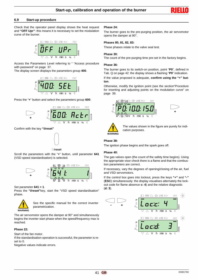
41 20081760GB
Start-up, calibration and operation of the burner
6.9 Start-up procedure
Check that the operator panel display shows the heat requestand “OFF Upr”: this means it is necessary to set the modulationcurve of the burner.
Access the Parameters Level referring to “ “Access procedurewith password” on page 37.The display screen displays the parameters group 400.
Press the “+” button and select the parameters group 600:
Confirm with the key “i/reset”
Scroll the parameters with the “+” button, until parameter 641(VSD speed standardisation) is selected.
Set parameter 641 = 1.Press the “i/reset”key, start the “VSD speed standardisation”phase.
The air servomotor opens the damper at 90° and simultaneouslybegins the inverter start phase when the speed/frequency max isreached.
Phase 22:
Start of the fan motor. If the standardisation operation is successful, the parameter is re-set to 0. Negative values indicate errors.
Phase 24:
The burner goes to the pre-purging position, the air servomotoropens the damper at 90°.
Phases 80, 81, 82, 83:
These phases relate to the valve seal test.
Phase 30:The count of the pre-purging time pre-set in the factory begins.
Phase 36:
The burner goes to its switch-on position, point “P0”, defined inTab. Q on page 42: the display shows a flashing “P0” indication.
If the value proposed is adequate, confirm using the “+” but-ton.
Otherwise, modify the ignition point (see the section“Procedurefor inserting and adjusting points on the modulation curve” onpage 39.
Phase 38:
The ignition phase begins and the spark goes off.
Phase 40:
The gas valves open (the count of the safety time begins). Usingthe appropriate visor check there is a flame and that the combus-tion parameters are correct.
If necessary, vary the degrees of opening/closing of the air, fueland VSD servomotors.
If the control box goes into lockout, press the keys “+” and “-”(ESC) simultaneously: the display visualises alternately the lock-out code for flame absence c: 4) and the relative diagnostic (d: 3).
WARNING
See the specific manual for the correct inverterparametrization.
D9
03
5
h min s %V
P
D9
023
P
V %sminh
h min s %V
P
D1
21
36
������
h min s %
P
D1
21
37
WARNING
The values shown in the figure are purely for indi-cation purposes.
D9
032
P
minh s %V
D9
00
7D
90
08
P
%sminV h
P
hV min s %

20081760 42 GB
Start-up, calibration and operation of the burner
Solve the problem, referring to the paragraph “Ignition failure” onpage 50.
To unlock, see “Reset procedure” on page 36. The display vis-ualises “OFF Upr”.
Repeat the "Start-up procedure".
Once the ignition has occurred (point “P0”), proceed with thecalibration of the modulation curve.
Press the button “+”: the display visualises the indicator “P1”flashing and proposes the same settings as point “P0”.
Press button “+” again: the display shows “CALC” for a few sec-onds.
The control box will automatically report the same values set inpoints “P0” and “P1” at points “P2” to “P8”.
Press “+” until point “P9” is reached.
Once point“P9” is reached wait for the display to show the flash-ing indicator “P9” proposing the same settings as point “P0”.
Now it is possible to change this value to obtain the maximum op-erating power desired.
If the gas pressure is insufficient, despite opening the gas servo-motor to a maximum of 90°, it is necessary to use the gas valvestabiliser.
After adjusting point “P9” keep the “-” key on the display pressedfor about 5 seconds, “CALC” appears for a few seconds.
The control box will automatically calculate the points from “P8”to “P2”, distributing them in a straight line. These are theoreticaland must be checked.
Check that the settings of point “P8” are adequate.
If not, modify the point.
Proceed in sequence, with the “-” button, up to point “P1”.
It is possible to modify point “P1” to obtain a minimum modulationpoint different to the ignition point (“P0”).
During the adjustment of each point, work on the air and gas ser-vomotors, without modifying the position of the gas valve stabilis-er.
Halfway through the procedure (i.e. around point P4 or P5), youare advised to measure gas delivery and check that the output isabout 50% of the maximum output.
If this is not the case, work also on the gas valve stabiliser: in thiscase however, it is necessary to revise the calibrations of all thepoints previously set.
Once the calibration of point “P1” is completed, confirm by press-ing the keys “+” and “-” (ESC) simultaneously: parameter “546”will appear.
If you want to make the burner work on the entire modulationcurve, press the “+” and “-” (ESC) keys simultaneously: in thisway, parameter “546” will automatically be assigned the value of100% and parameter “545” will have a value of 20%.
If you want to make the burner work on just a part of the modula-tion curve, modify the parameters “546” and “545” according tothe“Parameter modification procedure” on page 38.
Press the keys “+” and “-” (ESC) simultaneously twice, the dis-play will show the current load position.
Factory settings
Tab. Q
WARNING
The values previously inserted remain stored.
IMPORTANT
The purpose of this is to reach point “P9” to regu-late/determine the maximum operation output.
IMPORTANT
Before moving on from one point to the next, waitfor the servomotors to reach the position visual-ised on the display.
D9
041
h min s %V
P
D9
041
h min s %V
P
Point of the curve
Burner
RS 310/EV RS 410/EV RS 510/EV RS 610/EV
P0 air 5° 5° 5° 13°
gas 15° 15° 15° 25°
VSD 70% 70% 70% 70%
WARNING
At the end of the "Start-up procedure" it is nec-essary to carry out a "Backup", which is used tomemorise the parameters and the data in the con-trol box within the display RDI21…
This operation allows the parameters and thepoints of the modulation curve to be restored inthe event of problems.
It is advisable to perform a backup every time thata parameter is changed!
For the procedure see “Backup” on page 43.
D9
01
4
P
hV min s %
ESC

43 20081760GB
Start-up, calibration and operation of the burner
6.10 Backup / Restore procedure
At the end of the "Start-up procedure" it is wise to carry out abackup, creating a copy of the data memorised on the REC, inthe RDI 21 display panel.
This will allow the data to be used for programming a new RECor to return to the memorised settings of the same REC.
6.10.1 Backup
To perform the backup, proceed as follows: access the Parameters Level referring to “Access procedure
with password” on page 37 .
The display screen displays the parameters group 400.
With the key "-":
Select the parameters group 000:
The 000 parameter blinks, confirm using the "i/reset" key:
The display screen shows parameter 050 blinking:
Confirm with the key "i/reset":
The parameter bAC_UP appears on the display screen:
confirm with the key "i/reset":
The display screen shows the following value:
Use the button "+":
The value will be set to 1. Value 1 is flashing:
confirm with the button "i/reset" to activate the backup process.
The value 1 appears on the display screen:
After approx 5 seconds (it depends on the duration of the pro-gramme), the 0 value appears on the display screen, this is to in-dicate that the backup process has been completed correctly.
WARNING
We suggest that this operation be carried out atthe end of any intervention that involves modifica-tions to what has been set on the cam.
This will allow you to carry out a restore in a simplemanner on a new cam supplied as a replacementpart, without having to reprogramme the system.
D9
023
P
V %sminh
D1
214
0
h min s %
P
������
D1
214
1
h min s %
P
������
D1
21
42
h min s %
P
V
������
D1
214
3
h min s %
P
V
D1
21
44
h min s
P
V
������
D1
21
45
h min s %
P
V
D1
21
43
h min s %
P
V

20081760 44 GB
Start-up, calibration and operation of the burner
NOTE:If an error occurs during the backup process, the displayscreen shows a negative value. Refer to diagnostic code 137 to determine the cause of theerror (see section “List of error codes” on page 56).
6.10.2 Restore
To perform the restore procedure, proceed as follows: access the Parameters Level referring to “Access procedure
with password” on page 37 .
The display screen displays the parameters group 400.
With the key "-":
Select the parameters group 000:
The 000 parameter blinks, confirm using the "i/reset" key:
The display screen shows parameter 050 blinking:
Confirm with the key "i/reset":
The parameter bAC_UP appears on the display screen:
With the key "+"
select the rEStorE parameter
Confirm with the key "i/reset":
The display shows the following value.
Use the button "+":
The value will be set to 1. Value 1 is flashing:
confirm with the button "i/reset" to activate the restore process.
WARNING
It is advisable to perform a backup every timethat a parameter is changed, after checkingthat the modification carried out is correct.
WARNING
Use this procedure when replacing equipmentwith a parts code. In this way it is possible to havethe default parameters already memorised orthose memorised during the start-up.
This procedure cannot be carried out onequipment coming from other burners.
D9
02
3
P
V %sminh
D1
21
40
h min s %
P
������
D1
21
41
h min s %
P
������
D12
14
2
h min s %
P
V
D1
214
6
h min s %
P
V
������
D1
21
43
h min s %
P
V
D1
21
44
h min s
P
V
������

45 20081760GB
Start-up, calibration and operation of the burner
The value 1 appears on the display screen:
After approx 8 seconds (it depends on the duration of the pro-gramme), the 0 value appears on the display screen, this is to in-dicate that the restore process has been completed correctly.
NOTE:When the restore process is successfully completed, the 0value is shown on the display screen. Err C information: 136 D: 1 (restore process initialised) isdisplayed for a brief moment.
NOTE:If an error occurs during the backup process, the displayscreen shows a negative value. Refer to diagnostic code 137 to determine the cause of theerror (see section “List of parameters” on page 46).
IMPORTANT
At the end of the restore process, it is neces-sary to check the sequence of functions andthe list of parameters.
WARNING
It is advisable to perform a backup every timethat a parameter is changed, after checkingthat the modification carried out is correct.
D1
21
45
h min s %
P
V
D1
214
3h min s %
P
V

20081760 46 GB
Start-up, calibration and operation of the burner
6.10.3 List of parameters
ParameterNo. of
elements
Unit of measure-
ment
Modifica-tion
Values intervalDegree of precision
Predefined setting
Access modeNo. Description Min. Max.
000 INTERNAL PARAMETERS
050
Start backup/restore process via RDI21... / PC TOOL (set the parameter to 1)Index 0 = create backupIndex 1 = perform restoreNegative values indicate errors
2 - Modification -99 2 1 0; 0 Service mode
055Burner identification number created from the backup on RDI21...
1 - Reading only 0 99999999 1 0 Service mode
056 ASN number created by the backup on RDI21... 8 - Reading only 0 127 1 0 Service mode
057 Software Version created by the backup on RDI21... 1 - Reading only 0x100 0xFFF9 1 0 Service mode
100 GENERAL PARAMETERS
102 Control box identification date 1 - Reading only 0 255 1 Info mode
103 Control box identification number 1 - Reading only 0 65535 1 Info mode
104 Identification number of the group of parameters set 1 - Reading only 0 255 1 30 Info mode
105 Version of the group of parameters set 1 - Reading only 0 0xFFFF 1 V 01.08 Info mode
107 Software version 1 - Reading only 0 0xFFF9 1 V 03.30 Info mode
108 Software variation 1 - Reading only 0 225 1 1 Info mode
111ASN number to verify the ASN number created by the backup on RDI 21…
8 - Reading only 0 127 1 0 Service mode
113 Burner identification 1 - Modification 0 99999999 1 Not definedInfo Mode
with password Service Mode
121Manual setting of outputNot defined = automatic operation
1 %Modification /zero setting
0% 100% 0.1% Not defined Info mode
123
Minimum output step positionIndex 0: BACS outputIndex 1: output of the external load regulator, analogue.Index 2: output of the external load regulator contacts.
3 % Modification 0% 100% 0.1%0% ; 1%;
0%Service mode
124Beginning flame loss test (TÜV test)(define the parameter at 1)(switch of flame loss fuel valves) A negative value indicates an error (see code 150)
1 - Modification -6 1 1 0 Service mode
125Frequency of main power supply0 = 50 Hz1 = 60 Hz
1 - Modification 0 1 1 0 Service Mode
126 Brightness of display 1 % Modification 0% 100% 1% 75% Service Mode
128Fuel meter: Led pulse valence(led pulses / volumetric flow units)
1 - Modification 0 400 0,01 0 Service Mode
130
Eliminate visualisation error chronologyTo eliminate the visualisation, set the parameter to 1, then to 2Answer 0: process successfulAnswer -1: timeout of 1_2 - sequence
1 - Modification -5 2 1 0 Service Mode
133
Default output for TÜV test:Not valid for TÜV test when output is activated 2,000 ..... 10,000 = low flame or first / second / third stage
1 %Modification /zero setting
20% 100% 0.1% Not defined Service Mode
141
Remote management of control box0 = off1 = Modbus2 = reserved
1 - Modification 0 2 1 0 Service Mode
142
Standby time before a new attempt in event of com-munication faultSet values: 0 = not active1 = .... 7200 s
1 s Modification 0s 7200s 1s 120s Service Mode
143 Reserved 1 - Modification 1 8 1 1 Info Mode
144 Reserved 1 s Modification 10s 60s 1s 30s Service Mode
145Peripheral address for ModbusSet values:1 ... 247
1 - Modification 1 247 1 1 Service Mode
146
Baud Rate for ModbusSet values:0 = 96001 = 19200
1 - Modification 0 1 1 1 Service Mode

47 20081760GB
Start-up, calibration and operation of the burner
147
Parity for Modbus0 = none1 = odd2 = even
1 - Modification 0 2 1 0 Service Mode
148
Selection of the burner operation during the interrup-tion of the switch-over with the system of remote man-agement.With modulating operation the settings of the valuesare the following:0...19.9 = burner switched off20...100 = 20...100% modulation field of the burner.With stage operation: 0 = burner off P1, P2, P3No setting = no function in the event of communicationinterruption
1 %Modification /zero setting
0% 100% 0.1% Not defined Service Mode
161 Total number of errors 1 - Reading only 0 65535 1 0 Info mode
162 Hours of operation (that can be reset) 1 h Reset 0 h 999999h 1 h 0h Info mode
163 Total hours of power supply to control box 1 h Reading only 0h 999999h 1h 0h Info mode
164 Total number of start-ups (that can be reset) 1 - Reset 0 999999 1 0 Info mode
166 Total number of start-ups 1 - Reading only 0 999999 1 0 Info mode
167Volumetric delivery of fuel in the selected unit of meas-urement (that can be reset)
1m3, l,ft3, gal
Reset 0 99999999 1 0 Info mode
200 BURNER CHECKS
201
Burner operation mode (fuel supply line, modulating/stage, servomotors, etc.)-- = not defined (eliminate curves)1 = Gmod2 = Gp1 mod3 = Gp2 mod4 = Lo mod5 = Lo 2 stage6 = Lo 3 stage7 = Gmod pneu8 = Gp1 mod pneu9 = Gp2 mod pneu10 = LoGp mod11 = LoGp 2-stage12 = Lo mod 2 fuel valves13 = LoGp mod 2 fuel valves14 = G mod pneu without actuator15 = Gp1 mod pneu without actuator16 = Gp2 mod pneu without actuator17 = Lo 2-stage without actuator18 = Lo 3-stage without actuator19 = G mod only gas actuator20 = Gp1 mod only gas actuator21 = Gp2 mod only gas actuator22 = Lo mod only oil actuator
1 -Modify/set to
zero1 22 1 Not defined Service Mode
208
Stopping of the program0 = deactivated1 = pre-purging (Ph24)2 = Ignition (Ph36)3 = Interval 1 (Ph44)4 = Interval 2 (Ph52)
1 - Modification 0 4 1 0 Service Mode
210Alarm as the pre-purging phase begins;0 = Deactivated;1 = Activated
1 - Modification 0 1 1 0 Service Mode
211 Uphill train fan motor 1 s Modification 2s 60s 0.2s 2s Service Mode
212 Maximum time to reach low flame 1 s Modification 0.2s 10 min 0.2s 45s Service Mode
215
Maximum repeats of safety circuit1 = No repetition2...15 = Number of repetitions16 = Constant repetitions
1 - Modification 1 16 1 16 Service Mode
221Gas: selection of flame sensor0 = QRB.../ QRC1 = ION / QRA
1 - Modification 0 1 1 1 Service Mode
222Gas: Selection of the pre-purging function0 = deactivated1 = activated
1 - Modification 0 1 1 1 Service Mode
ParameterNo. of
elements
Unit of measure-
ment
Modifica-tion
Values intervalDegree of precision
Predefined setting
Access modeNo. Description Min. Max.

20081760 48 GB
Start-up, calibration and operation of the burner
223
Maximum repeats of minimum gas pressure switch intervention1 = No repetition2...15 = Number of repetitions16 = Constant repetitions
1 - Modification 1 16 1 16 Service Mode
225 Gas: pre-purging time 1 s Modification 20s 60 min 0.2s 20s Service Mode
226 Gas: pre-ignition time 1 s Modification 0.4 s 60 min 0.2s 2s Service Mode
230 Gas: interval 1 1 s Modification 1s 60s 0.2s 2s Service Mode
232 Gas: interval 2 1 s Modification 0.4 s 60s 0.2s 2s Service Mode
233 Gas: post-combustion time 1 s Modification 0.2s 60s 0.2s 8s Service Mode
234 Gas: Post-purging time (no extraneous light test) 1 s Modification 0.2s 108 min 0.2s 0.2s Service Mode
236
Gas: Minimum gas pressure switch input0 = deactivated1 = minimum gas pressure switch (upstream of the fuel valve 1 (V1))2 = valve control via the minimum pressure switch (between fuel vale 1 (V1) and 2 (V2))
1 - Modification 1 2 1 1 Service Mode
237
Gas: Maximum gas pressure switch / POC Input0 = deactivated1 = Maximum gas pressure switch2 = POC
1 - Modification 1 2 1 1 Service Mode
239Gas: Intermittent operation0 = deactivated1 = activated
1 - Modification 0 1 1 1 Service Mode
241
Gas: Valve leak detection test0 = test deactivated1 = valve leak detection test at start up2 = valve leak detection test at shutdown3 = valve leak detection test at start-up and at shut-down
1 - Modification 0 3 1 2 Service Mode
248Gas: Post-purging time (t3)(at deactivation of the load (LR)) - ON
1 s Modification 1s 108 min 0.2s 1s Service Mode
261Oil: selection of flame sensor0 = QRB.../ QRC...1 = ION / QRA...
1 - Modification 0 1 1 0 Service Mode
265 Oil: pre-purging time 1 s Modification 15s 60 min 0.2s 15s Service Mode
266 Oil: pre-ignition time 1 s Modification 0.6s 60 min 0.2s 2s Service Mode
270 Oil: interval 1 1 s Modification 0.4 s 60 min 0.2s 2s Service Mode
272 Oil: interval 2 1 s Modification 0.4 s 60 min 0.2s 2s Service Mode
273 Oil: post-combustion time 1 s Modification 0.2s 60s 0.2s 8s Service Mode
274 Oil: Post-purging time (no extraneous light test) 1 s Modification 0.2s 108 min 0.2s 0.2s Service Mode
276
Oil: Minimum input oil pressure switch0 = deactivated1 = activated from phase 382 = activated from safety time (TSA)
1 - Modification 1 2 1 1 Service Mode
277
Oil: Maximum oil pressure switch / POC Input0 = deactivated1 = Maximum oil pressure switch2 = POC
1 - Modification 1 2 1 1 Service Mode
279Oil: Intermittent operation0 = deactivated1= activated
1 - Modification 0 1 1 1 Service Mode
281Oil: selection transformer ignition phase TA0 = brief pre-ignition (Ph38)1 = long pre-ignition (with fan)(Ph22)
1 - Modification 0 1 1 1 Service Mode
284Oil: Post-purging time (t3)(at deactivation of the load (LR)) - ON
1 s Modification 1s 108 min 0.2s 1s Service Mode
400 AIR / FUEL MODULATION CURVES
401 Checking servomotor fuel (only curve setting) 13 (°) Modification 0° 90° 0.1°0°; 0°; 15°; Not defined
Service Mode
402 Checking servomotor air (only curve setting) 13 (°) Modification 0° 90° 0.1°0°; 90°; 45°; Not defined
Service Mode
403 VSD control curve ratio (only curve setting) 13 (°) Modification 20° 100° 0.1°0°; 100°; 50°; Not defined
Service Mode
500 POSITIONING OF SERVOMOTORS
ParameterNo. of
elements
Unit of measure-
ment
Modifica-tion
Values intervalDegree of precision
Predefined setting
Access modeNo. Description Min. Max.

49 20081760GB
Start-up, calibration and operation of the burner
501
Position of the fuel servomotor in absence of flameIndex 0 = standby positionIndex 1 = pre-purging positionIndex 2 = post-purging position
3 (°) Modification 0° 90° 0.1° 0°; 0°; 15° Service Mode
502
Position of the air servomotor in absence of flameIndex 0 = standby positionIndex 1 = pre-purging positionIndex 2 = post-purging position
3 (°) Modification 0° 90° 0.1° 0°; 90°; 45° Service Mode
503
VSD speed without flameIndex 0 = standby speedIndex 1 = pre-purging speedIndex 2 = post-purging speed
3 (°) Modification 0° 100° 0.1° 0°; 100°; 50° Service Mode
522 Acceleration 1 s Modification 5 s 20s 1s 10s Service Mode
523 Deceleration 1 s Modification 5 s 20s 1s 10s Service Mode
542
VSD/PWM activation
0 = Deactivated
1 = Activated
1 - Modification 0 1 1 0 Service Mode
545Minimum modulation limitNot defined = 20%
1 %Modification /zero setting
20% 100% 0.1% Not defined Service Mode
546Maximum modulation limitNot defined = 100%
1 %Modification /zero setting
20% 100% 0.1% Not defined Service Mode
600 SERVOMOTORS
606
Tolerance limit for position check (0.1°)Index 0 = fuelIndex 1 = airMore serious position error, where a defect has cer-tainly been detected- > Stop range: (P 606 - 0.6°) a P606
2 (°) Modification 0.5° 4° 0.1° 1.7°; 1.7° Service Mode
641
VSD speed standardisation controlNegative value error diagnostics (see error code 82)0 = standardisation deactivated1 = Standardisation active
1 - Modification -25 1 1 0 Service Mode
642Standardised speedIndex 0 = speed 1Index 1 = speed 2
2 - Reading only 650 6500 0.1 Not defined Service Mode
645
Analogue exit configuration0 = DC 0...10 V1 = DC 2...10 V2 = DC 0 / 2...10 V
1 - Modification 0 2 1 2 Service Mode
700 LOG OF THE ERRORS
701 Error chronology: 701-725.01.Code 25 - Reading only 0 255 1 0 Info mode
• Error chronology: 701-725.02.Diagnostic code 25 - Reading only 0 255 1 0 Info mode
• Error chronology: 701-725.03.Error class 25 - Reading only 0 6 1 0 Info mode
• Error chronology: 701-725.04.Phase 25 - Reading only 0 255 1 0 Info mode
• Error chronology: 701-725.05.Start-up meter 25 - Reading only 0 99999999 1 0 Info mode
725 Error chronology: 701-725.06.Load 25 % Reading only 0% 100% 0.1% 0% Info mode
900 PROCESS INFORMATION
903Actual outputIndex 0 = fuelIndex 1 = air
2 % Reading only 0% 100% 0.1% 0% Info mode
922Position of the servomotorsIndex 0 = fuelIndex 1 = air
2 (°) Reading only -50° 150° 0.01° 0° Info mode
935 Absolute speed 1 - Reading only 0 6553,5 0,1 0 Service mode
936 Standardised speed 1 % Reading only -200% 200% 0.1% 0% Info mode
942
Heat source active1 = output during the definition of the curves2 = manual output3 = BACS output4 = analogue input output5 = output of the external load regulator contacts
1 - Reading only 0 255 1 0 Service mode
ParameterNo. of
elements
Unit of measure-
ment
Modifica-tion
Values intervalDegree of precision
Predefined setting
Access modeNo. Description Min. Max.

20081760 50 GB
Start-up, calibration and operation of the burner
Tab. R
6.11 Operation
Burner without modulating operation kitOnce the start-up cycle is completed, the servomotor commandmoves on to the thermostat/pressure switch TR that controls thepressure or the temperature in the boiler. If the temperature or the pressure is low (so the thermostat/
pressure switch TR is closed), the burner progressivelyincreases the output as far as the MAX value (point “ P9”).
If the temperature or the pressure increases as far as theopening of the thermostat/pressure switch TR, the burnerprogressively reduces the output as far as the MIN value(point “P1”),. The sequence repeats endlessly.
The burner stops when the heat request is less than the heatsupplied by the burner at MIN output.
The thermostat/pressure switch TL opens, the control boxcarries out the switching off phase.
The air damper closes completely to reduce heat losses to aminimum.
As an alternative to control through TR, the command for burnermodulation can be made also using a 4-20 mA signal.
Burner with modulating operation kitSee manual enclosed with the adjuster kit.
6.12 Ignition failure
If the burner does not switch on, there is a lockout within 3s of theelectrical supply reaching the gas valve.
It may be that the gas does not arrive at the combustion headwithin the safety time of 3s.
In this case increase gas ignition flow rate. The arrival of gas tothe pipe coupling is displayed on the pressure gauge, as shownin (Fig. 37 on page 54).
947
Result of the sampling of the contact (codified in bits)Bit 0.0 = 1: Minimum pressure switchBit 0.1 = 2: Maximum pressure switchBit 0.2 = 4: Pressure switch control valvesBit 0.3 = 8: Air pressure switchBit 0.4 = 16: Open load checkBit 0.5 = 32: ON load checkBit 0.6 = 64: Closed load checkBit 0.7 = 128: Safety circuit Bit 1.0 = 1: Safety valveBit 1.1 = 2: IgnitionBit 1.2 = 4: Fuel valve 1Bit 1.3 = 8: Fuel valve 2Bit 1.4 = 16: Fuel valve 3/ pilot valveBit 1.5 = 32: Reset
2 - Reading only 0 255 1 0 Info mode
950
Relay request status (coded in bits)Bit 0 = 1: AlarmBit 1 = 2: Safety valve Bit 2 = 4: IgnitionBit 3 = 8: Fuel valve 1Bit 4 = 16: Fuel valve 2Bit 5 = 32: Fuel valve 3/ pilot valve
1 - Reading only 0 255 1 0 Info mode
954 Flame intensity 1 % Reading only 0% 100% 1% 0% Info mode
960 Actual output 1m3/h, l, h, ft3/h, gal/h
Reading only 0 6553,5 0,1 0 Info mode
961 Status of external modules and visualisation 1 - Reading only 0 255 1 0 Info mode
981 Memory error: Code 1 - Reading only 0 255 1 0 Info mode
982 Memory error: diagnostic code 1 - Reading only 0 255 1 0 Info mode
992 Error indicators 10 - Reset 00xFFFFFF
FF1 0 Service mode
ParameterNo. of
elements
Unit of measure-
ment
Modifica-tion
Values intervalDegree of precision
Predefined setting
Access modeNo. Description Min. Max.
WARNING
In the event the burner stops, in order to preventany damage to the installation, do not unblock theburner more than twice in a row.
If the burner locks out for a third time, contact thecustomer service.
DANGER
In the event there are further lockouts or faultswith the burner, the maintenance interventionsmust only be carried out by qualified, authorisedpersonnel, in accordance with the contents of thismanual and in compliance with the standards andregulations of current laws.

51 20081760GB
Start-up, calibration and operation of the burner
6.13 Burner flame goes out during operation
If the flame should go out during operation, the burner will lockoutwithin 1s.
6.14 Stopping of the burner
The burner can be stopped by: intervening on the disconnecting switch of the electrical sup-
ply line, located on the boiler panel; removing the transparent protection 30) Fig. 6 on page 14,
after unscrewing the relative screw.
There are now two possibilities:– using the operator panel according to the manual lockout pro-
cedure on pag. 35;– using the switch 0-1 of Fig. 28 on page 31.
6.15 Final checks (with burner operating)
Tab. S
Open the thermostat/pressure switch TL Open the thermostat/pressure switch TS The burner must stop
Turn the gas maximum pressure switch knob to the mini-mum end of scale position
Turn the air pressure switch knob to the maximum end ofscale position
The burner must stop in lockout
Turn off the burner and cut off the power Disconnect the minimum gas pressure switch connector The burner must not start
Disconnect the connector of the ionisation probe The burner must stop in lockout due to ignition failure
WARNING
Make sure that the mechanical locking systemson the various adjustment devices are fully tight-ened.

20081760 52 GB
Maintenance
7.1 Notes on safety for the maintenance
The periodic maintenance is essential for the good operation,safety, yield and duration of the burner.
It allows you to reduce consumption and polluting emissions andto keep the product in a reliable state over time.
Before carrying out any maintenance, cleaning or checking oper-ations:
7.2 Maintenance programme
7.2.1 Maintenance frequency
7.2.2 Safety test - with gas ball valve closed
It is fundamental to ensure the correct execution of the electricalconnections between the gas solenoid valves and the burner toperform safely the commissioning.
For this purpose, after checking that the connections have beencarried out in accordance with the burner's electrical diagrams,an ignition cycle with closed gas ball valve -dry test- must be per-formed.1 The manual ball gas valve must be closed2 The electrical contacts of the burner limit switch need to be
closed3 Ensures closed the contact of the low gas pressure switch4 Make a trial for burner ignition
The start-up cycle must be as follows:– Starting the fan for pre-ventilation– Performing the gas valve seal control, if provided– Completion of pre-ventilation– Arrival of the ignition point– Power supply of the ignition transformer– Electrical Supply of solenoid gas valves
Since the manual gas ball valve is closed, the burner will not lightup and its control box will go to a safety lockout condition.
The actual electrical supply of the solenoid gas valves can be ver-ified by inserting a tester. Some valves are equipped with lightsignals (or close/open position indicator) that turn on at the sametime as their power supply.
7.2.3 Checking and cleaning
CombustionThe optimum calibration of the burner requires an analysis of theflue gases. Significant differences with respect to the previousmeasurements indicate the points where most care should be ex-ercised during maintenance.
Combustion headOpen the burner and make sure that all components of thecombustion head are in good condition, not deformed by thehigh temperatures, free of impurities from the surroundingsand correctly positioned.
BurnerCheck that there are not excess wear or loosen screws.
Clean the outside of the burner.
FanCheck to make sure that no dust has accumulated inside the fanor on its blades, as this condition will cause a reduction in the airflow rate and provoke polluting combustion.
BoilerClean the boiler as indicated in its accompanying instructions inorder to maintain all the original combustion characteristics in-tact, especially the flue gas temperature and combustion cham-ber pressure.
Gas leaksMake sure that there are no gas leaks on the pipe between thegas meter and the burner.
7 Maintenance
DANGER
The maintenance interventions and the calibrationof the burner must only be carried out by qualified,authorised personnel, in accordance with the con-tents of this manual and in compliance with thestandards and regulations of current laws.
DANGER
Turn off the burner's power supply using the mainsystem switch.
DANGER
Turn off the fuel interception tap.
Wait for the components in contact with heatsources to cool down completely.
The gas combustion system should be checked atleast once a year by a representative of the man-ufacturer or another specialised technician.
WARNING
IF THE ELECTRICAL SUPPLY OF THE GAS VALVESOCCURS AT UNEXPECTED TIMES, DO NOT OPENMANUAL GAS BALL VALVE, SWITCH OFF POWERLINE; CHECK THE WIRES; CORRECT THE ERRORSAND REPEAT THE COMPLETE TEST.
The operator must use the required equipmentduring maintenance.

53 20081760GB
Maintenance
Gas filterChange the gas filter when it is dirty.
CombustionIf the combustion values measured before starting maintenancedo not comply with applicable legislation or do not indicate effi-cient combustion, consult the 7.2.4 or contact our Technical Sup-port Service to implement the necessary adjustments. It is advisable to set the burner according to the type of gas usedand following the indications in7.2.4.
Tab. T
7.2.4 Safety components
The safety components should be replaced at the end of their lifecycle indicated in the following table.
The specified life cycles do not refer to the warranty terms indi-cated in the delivery or payment conditions.
Tab. U
EN 676Air excess
Max. output. 1.2
Min. output 1.3
GASCO2 theoretical max. 0% O2
CO2 % Calibration CO NOX
= 1.2 = 1.3 mg/kWh mg/kWh
G 20 11.7 9.7 9.0 100 170
G 25 11.5 9.5 8.8 100 170
G 30 14.0 11.6 10.7 100 230
G 31 13.7 11.4 10.5 100 230
Safety
componentLife cycle
Flame control10 years or 250,000
operation cycles
Flame sensor10 years or 250,000
operation cycles
Gas valves (solenoid)10 years or 250,000
operation cycles
Pressure switches10 years or 250,000
operation cycles
Pressure adjuster 15 years
Servomotor (electronic cam )(if present)
10 years or 250,000
operation cycles
Oil valve (solenoid) (if pres-ent)
10 years or 250,000
operation cycles
Oil regulator (if present)10 years or 250,000
operation cycles
Oil pipes/ couplings (metallic)(if present)
10 years
Flexible hoses (if present)5 years or 30,000 pressurised cy-
cles
Fan impeller 10 years or 500,000 start-ups

20081760 54 GB
Maintenance
7.2.5 Measuring the ionisation current
The burner is fitted with an ionisation system to check that aflame is present.
The minimum current for control box operation is 4 µA. The oper-ator panel displays “30%” (see “List of parameters” on page 46,parameter no. 954).
The burner provides a much higher current, so controls are notnormally required.
However, if it is necessary to measure the ionisation current, dis-connect the plug-socket on the ionisation probe cable and inserta direct current microammeter with a base scale of 100 µA, asshown in Fig. 36.
7.2.6 Checking the air and gas pressure on the combustion head
To carry out this operation it is necessary to use a pressure gaugeto measure the air and gas pressure at the combustion head, asshown in Fig. 37.
7.3 Checking the position of the rpm sensor
To calibrate the rpm sensor, proceed as follows:
loosen the screws 3) rest the sensor on the disc extension 2).
Take the scale 4) as a reference, pull back the rpm sensor byabout a notch so that the distance from the disc extension 2) isabout 2 mm.
Key (Fig. 38)
1 - Rpm sensor
2 - Disc
3 - Screw
4 - Scale
WARNING
Carefully check the polarities!
Fig. 3620076585
20076586
Checkingair pressure
Checkinggas pressure
Fig. 37
2
13
3
2
4
20082216
Fig. 38

55 20081760GB
Maintenance
7.4 Opening the burner
To open the burner, use the same procedure set out in “Accessto head internal part” on page 23.
7.5 Closing the burner
Refit following the steps described but in reverse order; refit allburner components as they were originally assembled.
DANGER
Turn off the burner's power supply using the mainsystem switch.
DANGER
Turn off the fuel interception tap.
Wait for the components in contact with heatsources to cool down completely. 2
2 4
1
10
1
2
2
93
5
11
Fig. 3920078008
After carrying out maintenance, cleaning orchecking operations, reassemble the cover andall the safety and protection devices of the burner.

20081760 56 GB
Faults - Possible causes - Solutions
If faults arise in ignition or operations, the burner performs a"safety stop", which is signalled by the red burner lockout LED.
The display of the operator panel visualises alternately the lock-out code and the relative diagnostic.
To restore start-up conditions, refer to the “Reset procedure” onpage 36.
When the burner starts up again, the red LED goes out.
8.1 List of error codes
8 Faults - Possible causes - Solutions
WARNING
In the event the burner stops, in order to preventany damage to the installation, do not unblock theburner more than twice in a row.
If the burner locks out for a third time, contact thecustomer service.
DANGER
In the event there are further lockouts or faultswith the burner, the maintenance interventionsmust only be carried out by qualified, authorisedpersonnel, in accordance with the contents of thismanual and in compliance with the standards andregulations of current laws.
Error code
Diagnostic code Meaning of the REC 37.400A2 system Recommended measures
No Comm No communication between REC 37.400A2 and RDI21…
Check the wiring between the control box REC 37.400A2 and display RDI21…
2 # No flame at the end of TSA1
1 No flame at the end of safety time 1 (TSA1)
2 No flame at the end of safety time 2 (TSA2)
4No flame at the end of safety time 1 (TSA1)(software version V02.00)
3 # Air pressure error
0 Air pressure switch off
1 Air pressure switch on
4 Air pressure on – Lockout alarm at start
20 Air pressure, fuel pressure on - Alarm lock at start
68 Air pressure, POC on – Alarm lockout at start
84 Air pressure, fuel pressure, POC on - Alarm lockout at start
4 # Extraneous light
0 Extraneous light during start-up
1 Extraneous light during switch-off
2 Extraneous light during start-up – Lockout alarm at start
6Extraneous light during start-up, air pressure - Alarm lockout at start
18Extraneous light during start-up, fuel pressure - Alarm lockout at start
24Extraneous light during start-up, air pressure, fuel pressure - Alarm lockout at start
66Extraneous light during start-up, POC – Alarm lockout at start
70Extraneous light during start-up, air pressure, POC - Alarm lockout at start
82Extraneous light during start-up, fuel pressure, POC - Alarm lockout at start
86Extraneous light during start-up, air pressure, fuel pressure, poc - Alarm lockout at start
7 # Loss of flame
0 Loss of flame
3 Flame loss (software version V02.00)
3…255 Flame loss during TÜV test (flame loss test)
The diagnostics covers the period of time from the closure of thefuel valves to the point the flame loss was detected (resolution0.2 s value 5 = 1 s).
12 # Valve leak detection control
0 V1 leaks
Leak testCheck if the valve on the side of the gas has any leaks.Check the wiring and make sure that the circuit is open.

57 20081760GB
Faults - Possible causes - Solutions
1 V2 leaks
Leak testCheck if the valve on the side of the burner has any leaks.Check if the pressure switch for the leak test (PGVP) is closed when gas pressure is not present.Check the wiring and check if there is a short circuit.
2 Valve leak detection test not possibleThe valve leak detection is active, but the minimum gas pressure switch is selected as input for X9-04 (check parameters 238 and 241)
3 Valve leak detection test not possibleThe valve leak detection is active, but no input has been assigned (check parameters 236 and 237)
4 Valve leak detection not possibleValve leak detection is active, but 2 inputs have already been assigned (configure parameter 237 or maximum gas Pressure switch or POC)
5 Valve leak detection not possibleThe valve leak detection is active, but 2 inputs have been assigned (check parameters 236 and 237)
14 # POC
0 POC Open Check if the closure contact of the valve is closed
1 POC Closed Check the wiringCheck if the closure contact of the valve opens when the valve is checked
64 POC Open - Alarm lockout at start Check the wiringCheck if the closure contact of the valve is closed
19 80 Fuel pressure, POC - Alarm lockout at startCheck that the pressure switch is closed when no pressure is present from the fuelCheck that there are no short-circuits
20 # Pmin
0 Minimum gas/oil pressure absent Check that there are no line interruptions
1 Scarcity of gas - Alarm lockout at start Check that there are no line interruptions
21 # Pmax/POC
0Pmax: Max. gas/oil pressure exceededPOC: POC open (software version V02.00)
Check the wiring.POC: check whether the closure contact of the valve is closed
1 POC closed (software version V02.00)
Check the wiring.Check if the closure contact of the valve opens when the valve is checked
64POC Open - Lockout alarm at the start (software version V02.00)
Check the wiring.Check if the contact of the valve opens when the valve is checked
22OFF S
# Safety circuit/Burner flange
0 Safety circuit open /Burner flange open
1Safety circuit open /Burner flange open - Alarm lockout at start
3Safety circuit open /Burner flange open, extraneous light - Alarm lockout at start
5Safety circuit open /Burner flange open, extraneous light - Alarm lockout at start
17Safety circuit open /Burner flange open, extraneous light - Alarm lockout at start
19Safety circuit open /Burner flange open, extraneous light - Alarm lockout at start
21Safety circuit open /Burner flange open, extraneous light - Alarm lockout at start
23Safety circuit open /Burner flange open, extraneous light, air pressure, fuel pressure - Alarm lockout at start
65Safety circuit /Burner flange open, POC - Alarm lockout at start
67Safety circuit open /Burner flange open, extraneous light, POC - Alarm lockout at start
69Safety circuit open /Burner flange open, air pressure, POC - Alarm lockout at start
71Safety circuit open /Burner flange open, extraneous light, air pressure, POC - Alarm lockout at start
81Safety circuit open /Burner flange open, fuel pressure, POC - Alarm lockout at start
83Safety circuit open /Burner flange open, extraneous light, air pressure, POC - Alarm lockout at start
Error code
Diagnostic code Meaning of the REC 37.400A2 system Recommended measures

20081760 58 GB
Faults - Possible causes - Solutions
85Safety circuit open /Burner flange, air pressure, fuel pressure, POC - Alarm lockout at start
87Safety circuit open /Burner flange, extraneous light, air pressure, fuel pressure, POC - Alarm lockout at start
50 ÷ 58 # Internal errorCarry out a reset; if the error arises repeatedly, replace the control box
60 0 Internal error: no valid load checking deviceCarry out a reset; if the error arises repeatedly, replace the control box
65 ÷ 67 # Internal errorCarry out a reset; if the error arises repeatedly, replace the control box
70 #Fuel/air checking error: Calculation position in modulation
23 Invalid load No valid load
26 Curve points not defined Adjust the curve points of all the actuators
71 # Special position not defined
0 Standby position Set the standby position of all the servomotors used
1 Pre-purging position Set the pre-purging position of all the servomotors used
2 Post-purging position Set the post-purging position of all the servomotors used
3 Ignition position Set the ignition position of all the servomotors used
72 # Fuel/air internal checking error:Carry out a reset; if the error arises repeatedly, replace the control box
73 #Fuel/air internal checking error: multistep calculation position
23 Position calculation, invalid stage load No valid load
26 Position calculation, stage curve points not defined Adjust the curve points of all the servomotors
75 #Fuel/air ratio internal checking error: cyclical data check
1 Check synchronisation data, different current load
2 Check synchronisation data, different target load
4 Check synchronisation data, different target positions
16 Check synchronisation data, different positions reached
May be caused by different standardisation speeds (for example following the resetting of the data set) when the VSD is active -> perform the standardisation again and check the regulation of the fuel/air ratio.
76 # Fuel/air internal checking error:Carry out a reset; if the error arises repeatedly, replace the control box
80 # VSD control range limit
The standard unit could not correct the speed difference and has reached a limit in the control range.1. The base unit is not standardised for this motor----> repeat the standardisation. WARNING!check the settings of the air/fuel ratio control!
2. The VSD train times are not shorter than those of the standard unit (parameters 522, 523). 3. The VSD characteristic is not linear. The VSD voltage input configuration must correspond with that of the standard unit (parameter 645). 4. The VSD does not follow the changes of the standard unit quickly enough. Check the VSD settings (input filter, slide compensation, different latent speeds).
1 Lower control range limit The VSD speed was too high
2 Upper control range limit The VSD speed was too low
81 1 Interruption in speed limit inputExcessive electromagnetic interference on the sensor line -> improve the EMC
82 # Error during VSD speed standardisation
1Standardisation time-out (the descent time of the VSD train is too long)
Time-out at the end of the standardisation, during deceleration of VSD 1. The VSD train times are not shorter than those of the standard unit (parameter: 523)
2 Logging of the standardised speed not successfulError during the logging of the standardised speed ---> block the standard unit, reset it and repeat the standardisation
Error code
Diagnostic code Meaning of the REC 37.400A2 system Recommended measures

59 20081760GB
Faults - Possible causes - Solutions
3 Speed sensor circuit open
The standard unit does not receive pulses from the speed sensor: 1. The motor does not turn. 2. The speed sensor is not connected. 3. The speed sensor is not activated by the sensor disc (check the distance)
4Variation in speed / VSD acceleration time too long / speed below the minimum limit for standardisation
The motor has not reached a stable speed after acceleration. 1. The VSD train times are not shorter than those of the standard unit (parameters 522, 523).2. The VSD characteristic is not linear. The VSD voltage input configuration must correspond with that of the standard unit (parameter 645). 3. The VSD does not follow the changes of the standard unit quickly enough. Check the VSD settings (input filter, slide compensation, different latent speeds).4. The VSD speed is below the minimum for standardisation (650 rpm).
5 Incorrect rotation direction
The motor rotation direction is incorrect. 1. The motor does not rotate in the correct direction ---> modify the parameterisation of the rotation direction, or invert 2 phases. 2. The sensor disc is incorrectly assembled ---> turn the sensor disc.
6 Implausible speed sensor signals
The required pulse pattern (60°, 120°, 180°) has not been correctly identified. 1. The speed sensor does not detect all the noses of the sensor disc ---> check the distance 2. When the motor turns, other metal parts are detected along with the noses ---> improve the assembly. 3. Electromagnetic interference on the sensor lines ---> check the cable path, improve the EMC
7 Standardised speed not validThe standardised speed measured is not within the allowed range. 1. The motor turns too slowly or too quickly.
15 Speed deviation µC1 + µC2
Microcomputer speeds 1 and 2 have an excessive deviation. This may be caused by incorrect standardised speeds (e.g. after the reintegration of a set of data in a new unit)---> repeat the standardisation and check the air/fuel ratio.
20 Incorrect phase of the phase controllerThe standardisation was performed in the wrong phase. The only phases allowed are 12 ---> controller OFF, restart the standardisation.
21 Safety loop/burner flange openThe safety loop or burner flange is open ---> repeat the standardisation with the safety loop closed
22 Pneumatic actuator without reference
The air actuator has no reference, or has lost it. 1. Check whether the reference position can be approached. 2. Check whether the actuators have been swapped over. 3. If the error only arises after the start of standardisation, the actuator may be overloaded and unable to reach its destination.
23 VSD deactivatedThe standardisation was started with the VSD deactivated ---> activate the VSD and repeat the standardisation
24 No valid operation modeThe standardisation was started without a valid operation mode ---> activate a valid operation mode and repeat the standardisation
25 Pneumatic control of the air/fuel ratioThe standardisation was started with a pneumatic control of the air/fuel ratio ---> it is not possible to carry out the standardisation with a pneumatic control of the air/fuel ratio
128 Run command without prior standardisation The VSD is controlled but not standardised ---> perform the standardisation
255 No standardised speed availableThe motor turns but is not standardised ---> perform the standardisation
83 # VSD speed error The required speed has not been reached
Bit 0 Valence 1
Lower control range limit The speed was not reached because the control range limit was activated ---> for the measurements, see error code 80
Bit 1 Valence 2...3
Greater control range limit The speed was not reached because the control range limit was activated ---> for the measurements, see error code 80
Error code
Diagnostic code Meaning of the REC 37.400A2 system Recommended measures

20081760 60 GB
Faults - Possible causes - Solutions
Bit 2Valence 4...7
Stop caused by electromagnetic interferenceThe speed has not been reached because there are too many electromagnetic interferences on the sensor line. For the measurements, see error code 81.
Bit 3Valence 8
Curve too steep in terms of train speed
The speed was not reached because the curve was too steep. 1. With a train REC3... of 20 s, the speed variation between 2 points of the curve (in modulating mode) cannot exceed 10%. With a train REC3... of 10 s, the speed variation between 2 points of the curve (in modulating mode) cannot exceed 20%. With a train REC3... of 5 s, the speed variation between 2 points of the curve (in modulating mode) cannot exceed 40%. ---> Between the ignition point (P0) and the low flame point (P1), the speed in modulating mode may vary by a maximum of 40%, regardless of the train REC3…. 2. The VSD train must be about 20% faster than the train of the standard unit (parameters 522, 523).
Bit 4Valence 16
Speed signal interruption
No speed detected, despite the control. 1. Check whether the motor turns. 2. Check whether the speed sensor provides a signal (LED / check the distance from the sensor disc). 3. Check the VSD wiring.
Bit 5 Valence 32
Quick switch-off due to excessive speed deviation
For about 1 s, the speed deviation was >10% outside the envisaged range. 1. Check the train times of REC3.... and VSD. 2. Check the VSD wiring.
84 # Servomotors curve slope
Bit 0 Valence 1
VSD: Curve too steep in terms of train speed
1. With a train REC3... of 20 s, the speed variation between points of the curve (in modulating mode) cannot exceed 10%With a train REC3... of 10 s, the speed variation between points of the curve (in modulating mode) cannot exceed 20%2. With a train REC3... of 5 s, the speed variation between points of the curve (in modulating mode) cannot exceed 40%---> Between the ignition point (P0) and the low flame point (P1), the speed in modulating mode may vary by a maximum of 40%, regardless of the train REC3….The VSD train must be about 20% faster than the train of the standard unit (parameters 522, 523)
Bit 1Valence 2..3
Fuel servomotor: Curve too steep in terms of train ratioThe slope of the curve can correspond to a maximum position variation of 31° between 2 points of the modulation curve
Bit 2Valence 4..7
Air servomotor: Curve too steep in terms of train ratioThe slope of the curve can correspond to a maximum position variation of 31° between 2 points of the modulation curve
85 # Reference error of a servomotor
0 Reference error of the fuel servomotor
The reference of the fuel servomotor was not successful. It was not possible to reach the reference point.1. Check if the servomotors have been inverted.2. Check if the servomotor is blocked or overloaded.
1 Reference error of the air servomotor
The reference of the air servomotor was not successful.It was not possible to reach the reference point.1. Check if the servomotors have been inverted.2. Check if the servomotor is blocked or overloaded.
Bit 7Valence 128
Reference error owing to parameter modification
The parameterisation of an actuator (e.g. the reference position) has been modified. This error will be visualised to start up a new reference.
86 # Fuel servomotor error
0 Position error
It was not possible to reach the target position within the required range ---> Check to see if the servomotor is blocked or overloaded.
Bit 0Valence 1
Circuit openOpen circuit detected on the connection of the servomotor ---> Check the wiring (voltage between pins 5 or 6 and 2 of the X54 connector should be > 0.5 V).
Bit 3Valence 8
Curve too steep in terms of train ratioThe slope of the curve can correspond to a maximum position modification of 31° between 2 points of the modulation curve.
Bit 4Valence 16
Deviation of section compared with the last reference
Overloading of the servomotor or servomotor subjected to mechanical torsion.1. Check if the servomotor is blocked in any point along its range of action.2. Check if the torque is sufficient for the application.
Error code
Diagnostic code Meaning of the REC 37.400A2 system Recommended measures

61 20081760GB
Faults - Possible causes - Solutions
87 # Air servomotor error
0 Position errorIt was not possible to reach the target position within the requested tolerance range.1. Check if the servomotor is blocked or overloaded.
Bit 0Valence 1
Circuit openOpen circuit detected on the connection of the servomotor ---> Check the wiring (voltage between pins 5 or 6 and 2 of the X54 connector should be > 0.5 V).
Bit 3Valence 8
Curve too steep in terms of train ratioThe slope of the curve can correspond to a maximum position modification of 31° between 2 points of the modulation curve.
Bit 4Valence 16
Deviation of section compared with the last reference
Overloading of the servomotor or servomotor subjected to mechanical torsion.1. Check if the servomotor is blocked in any point along its range of action.2. Check if the torque is sufficient for the application.
90 - 91 # Burner internal checking error
93 # Flame signal acquisition error
3 Short circuit of the sensorShort circuit in the QRB sensor...1. Check the wiring.2. Flame detector probably faulty.
95 # Relay supervision error
3 Ignition transformers4 Fuel valve 15 Fuel valve 26 Fuel valve 3
External power supply - Contact active Check the wiring
96 # Relay supervision error
3 Ignition transformers4 Fuel valve 15 Fuel valve 26 Fuel valve 3
The relay contacts have joined together
Check the contacts:1. Control box connected to the power supply: the fan output must be without voltage.2. Disconnect the power supply. Disconnect the fan. The resistive connection between the fan output and the neutral wire is not allowed.If one of the 2 tests fails, replace the control box because the contacts are definitively joined together and it is no longer possible to guarantee safety.
97 # Relay supervision error
0The safety relay contacts have joined together or the safety relay has been powered by an external power supply
Check the contacts:1. Control box connected to the power supply: the fan output must be without voltage.2. Disconnect the power supply. Disconnect the fan. The resistive connection between the fan output and the neutral wire is not allowed.If one of the 2 tests fails, replace the control box because the contacts are definitively joined together and it is no longer possible to guarantee safety.
98 # Relay supervision error
2 – Safety valve3 Ignition transformers4 Fuel valve 15 Fuel valve 26 Fuel valve 3
The relay does not start up Carry out a reset; if the error arises repeatedly, replace the unit
99 # Relay internal checking errorCarry out a reset; if the error arises repeatedly, replace the control box
3 Relay internal checking error
Carry out a reset; if the error arises repeatedly, replace the control boxSoftware version V03.10: If error C:99 D:3 occurs during the standardisation of the VSD, temporarily deactivate the Alarm function at the start of the pre-purging phase (parameter 210 = 0) or interrupt the signal controller-ON
100 # Relay internal checking errorCarry out a reset; if the error arises repeatedly, replace the control box
105 # Contact sampling internal error
Error code
Diagnostic code Meaning of the REC 37.400A2 system Recommended measures

20081760 62 GB
Faults - Possible causes - Solutions
0 Min. pressure switch1 Max. pressure switch2 Valve operation test pressure switch3 Air pressure4 Load controller open5 Load controller on/off6 Load controller closed7 Safety loop / burner flange8 Safety valve9 Ignition transformers10 Fuel valve 111 Fuel valve 212 Fuel valve 313 Reset
Blocked upon irregularityCan be caused by capacitive loads or presence of DC voltage on the main power supply of the control box. The diagnostic code indicates the input in which the problem arose
106 ÷ 108 # Contact request internal errorCarry out a reset; if the error arises repeatedly, replace the control box
110 # Voltage monitoring test internal errorCarry out a reset; if the error arises repeatedly, replace the control box
111 0 Low level of power supplyInsufficient mains voltage.Conversion of the diagnostic code ---> Voltage value (230 V AC : 1,683)
112 0 Reset power supply voltageError code for the carrying out of a reset in the event of power supply restoration (absence of error)
113 # Mains voltage supervision internal errorCarry out a reset; if the error arises repeatedly, replace the control box
115 # Control box meter internal error
116 0Life cycle of the control box in the critical interval (250,000 Start ups)
The envisaged life cycle of the control box has been exceeded. Replace it.
117 0 Life cycle of the control box exceeded The switch-off threshold has been reached.
120 0 Interruption of fuel limiting meter inputToo many disturbance impulses on the input of the fuel meter ---> Improve the electromagnetic compatibility.
121 ÷ 124 # EEPROM access internal errorCarry out a reset, repeat and check the last setting of the parameters. Restore the group of parameters: if the error arises repeatedly, replace the control box.
125 # EEPROM reading access internal errorCarry out a reset, repeat and check the last setting of the parameters. If the error arises repeatedly, replace the control box.
126 # EEPROM writing access internal errorCarry out a reset, repeat and check the last setting of the parameters. If the error arises repeatedly, replace the control box.
127 # EEPROM access internal errorCarry out a reset, repeat and check the last setting of the parameters. Restore the group of parameters: if the error arises repeatedly, replace the control box.
128 0EEPROM access internal error - synchronisation during the initialisation
Carry out a reset; If the error arises repeatedly, replace the control box.
129 #EEPROM access internal error – command synchronisation
Carry out a reset, repeat and check the last setting of the parameters. If the error arises repeatedly, replace the control box.
130 # EEPROM access internal error - time-outCarry out a reset, repeat and check the last setting of the parameters. If the error arises repeatedly, replace the control box.
131 # EEPROM access internal error - page interruptedCarry out a reset, repeat and check the last setting of the parameters. If the error arises repeatedly, replace the control box.
132 # EEPROM register initialisation internal errorCarry out a reset; if the error arises repeatedly, replace the control box.
133 ÷ 135 #EEPROM access internal error – request synchronisation
Carry out a reset, repeat and check the last setting of the parameters. If the error arises repeatedly, replace the control box.
136 1 Restoration started The restoration of a backup has been started (no error)
137 # Internal error – backup / restoration
157 (-99)Restoration – OK, but backup < compared with set data of current system
Restoration successful, but the backup data installed are fewer than those currently present in the system.
239 (-17) Backup - logging of the backup on RDI21… failed Perform the reset and repeat backup
240 (-16) Reset - no backup in RDI21… No backup in RDI21…
241 (-15) Reset - Interruptions relating to impracticable ASN The backup has an impracticable ASN and cannot reset the unit
242 (-14) Backup – the backup carried out is contradictory The backup is irregular and cannot be transferred again
243 (-13)Backup – the data comparison between the internal microprocessors is irregular
Repeat the reset and backup
Error code
Diagnostic code Meaning of the REC 37.400A2 system Recommended measures

63 20081760GB
Faults - Possible causes - Solutions
244 (-12) The backup data are incompatible The backup data are incompatible with the current version of the software; the restoration is not possible
245 (-11) Error in access to the parameter Restore_Complete Repeat the reset and backup
246 (-10) Restoration – time-out during logging in EEPROM Repeat the reset and backup
247 (-9) The data received are contradictory The series of backup data is not valid; restoration is not possible
248 (-8) The restoration cannot currently be carried out Repeat the reset and backup
249 (-7)Restoration – interruption caused by inadequate identification of the burner
The backup has an inadequate identification of the burner and must not be transferred to the control box
250 (-6) Backup – the CRC of a page is not correct The series of backup data is not valid; restoration is not possible
251 (-5) Backup – the identification of the burner is not defined Define the identification of the burner and repeat the backup
252 (-4) After restoration, the pages are still in INTERRUPTION Repeat the reset and backup
253 (-3) The restoration cannot currently be carried out Repeat the reset and backup
254 (-2) Interruption owing to transmission error Repeat the reset and backup
255 (-1) Interruption owing to time-out during the restoration Carry out a reset, check the connections and repeat the backup
146 # Time-out of the system automation interface Refer to the Modbus User Documentation (A7541)
1 Modbus time-out
150 # TÜV test
1 (-1) Invalid phase The TÜV test can only be started in phase 60 (operation)
2 (-2) The TÜV test default output is too lowThe output of the TÜV test must be lower than the minor output limit
3 (-3) The TÜV test default output is too highThe output of the TÜV test must be greater than the upper output limit
4 (-4) Manual interruption No error: Manual interruption of the TÜV test by the user
5 (-5) TÜV test time-out
No flame loss after the fuel valves have been closed1. Check for any extraneous lights2. Check that there are no short-circuits3. Check whether one of the valves is leaking
165 # Internal error
166 0 Watchdog reset internal error
167 # Manual lockout The control box has been manually blocked (no error)
1 Manual lockout from remote reset command
2 Manual lockout from RDI21…
3 Manual lockout from PC interface
8Manual lockout from RDI21…Time-out/interrupted communication
During a regulation of the curve via the operating panel RDI21…the time-out for the operating menu is passed (setting via the 127 parameter), or else the communication between REC 37.400A2 and RDI21... has been interrupted
9Manual lockout from PC interfaceCommunication interrupted
During an adjustment of the curve via the PC interface, the communication between REC 37.400A2 and the operator panel has been interrupted for more than 30 seconds
33Manual lockout after the PC tool has performed a tentative reset
The PC tool has performed a tentative reset, even if the system has worked correctly
168 ÷ 171 # Internal error managementCarry out a reset; if the error arises repeatedly, replace the control box
200 OFF # System free of errors No error
201 OFF UPr
# Lockout or error at start Lockout or error due to lack of unit parameter settings
Bit 0Valency 1
No valid operation mode
Bit 1Valency 2..3
No fuel train defined
Bit 2Valency 4..7
No curve defined
Bit 3Valency 8..15
Standardisation speed not defined
Bit 4Valency 16..31
Backup / Reset impossible
202 # Selection of internal operation mode Redefine the operation mode (parameter 201)
203 # Internal error
Redefine the operation mode (parameter 201)Carry out a reset; if the error arises repeatedly, replace the control box
Error code
Diagnostic code Meaning of the REC 37.400A2 system Recommended measures

20081760 64 GB
Faults - Possible causes - Solutions
Tab. V
204 Phase number Program stop The program stop is active (no error)
205 # Internal errorCarry out a reset; if the error arises repeatedly, replace the control box
206 0Combination of control box and operator panel not allowed
207 # Compatibility of control box with operator panel
0 Obsolete version of control box
1 Obsolete version of operator panel
208 - 209 # Internal errorCarry out a reset; if the error arises repeatedly, replace the control box
210 0The selected operating mode is not released for the standard unit
Select an operating mode released for the standard unit
240 # Internal errorCarry out a reset; if the error arises repeatedly, replace the control box
245 # Internal errorCarry out a reset; if the error arises repeatedly, replace the control box
250 # Internal errorCarry out a reset; if the error arises repeatedly, replace the control box
Error code
Diagnostic code Meaning of the REC 37.400A2 system Recommended measures

65 20081760GB
Appendix - Accessories
Kit for modulating operation
Inverter (VSD)
UV flame sensor kit
Soundproofing box kit
Continuous purging kit
Software interface kit (ACS410 + OCI410.30) - Service Level
A Appendix - Accessories
Burner Output regulator Code
All models RWF 50.2 3-POINT OUTLET 20085417
All models RWF 55.5 COMPLETE WITH RS-485 INTERFACE 20074441
All models RWF 55.6 COMPLETE WITH RS-485/PROFIBUS INTERFACE 20074442
Burner Probe Adjustment field Code
All models PT 100 temperature - 100...+ 500°C 3010110
All models 4 - 20 mA pressure 0...2.5 bar 3010213
All models 4 - 20 mA pressure 0...16 bar 3010214
BurnerLine
voltage Motor Output
(kW)Inverter Output
(kW)Code
RS 310/EV 230V 7.5 7.5 20083590
RS 310/EV 400V 7.5 7.5 20028307
RS 410/EV 230V 9.2 11 20083611
RS 410/EV 400V 9.2 11 3090952
RS 510/EV 400V 12 15 3090960
RS 610/EV 400V 15 15 3090960
WARNING
The use of inverters other than those indicated by the manufacturer may lead to burner failure and,in extreme cases, a potential risk of harm to people and damage to property.
The manufacturing company shall not be liable for any such damage arising from non-observance ofthe requirements contained in this manual.
WARNING
Burner Code
Only FS1 models 20077814
Burner Type dB(A) Code
All models C7 10 3010376
Burner Code
All models 20077810
Burner Code
All models 3010436

20081760 66 GB
Appendix - Accessories
Modbus interface kit
PVP kit (Seal control function - See gas train booklet)
Gas trains in compliance with EN 676
Please refer to manual.
Burner Model Code
All models OCI412 3010437
Burner Ramp type Code
All models MB - CB 3010344

67 20081760GB
Appendix - Electrical panel layout
B Appendix - Electrical panel layout
Index of layouts
2 Indication of references
3 Single-wire output layout
4 Single-wire output layout
5 Functional layout REC 37...
6 Functional layout REC 37...
7 Functional layout REC 37...
9 Electrical wiring of internal output power regulator
10 Electrical wiring that the installer is responsible for
11 Electrical wiring that the installer is responsible for
12 Output power regulator inputs/outputs
1
2
Sheet no.
/1.A1
Co-ordinates
Indication of references

20081760 68 GB
Appendix - Electrical panel layout
���
������
�
���
�
���
��
��
���
��
� �
� �
���
���
��
� �
� �
���
���
����
�������
���
��� ��
�
�
��
��
�
�
��
��
�
� ! " # $ �
� ! " # $ �
�"�$
�����%�%&�
'$�#%�()
*$�+
�&�
,)�
*�)�
���%�%&�
'�)�
*(�*
$%�#
'��*
%�$�
�&$%�*
����
�"�$
��
�"�$
�����%�%&�
%'$�#$
�(�%��
��"
$
��������-��
������
�
&&�
&�($
.!"
��,$
!�!�!�
.!!
���
���
/���"�
'$"��000
��#
-�0�
��
�
�
�,��
,$���
�����
/��
.!!
��
($
���� �($
��
($
.!"
����
%��$'
*$'��!!
��"�
���
��,$!�!�!�
!�
!�
�')'
��1�
���-
����
�
�
/��
�
"��)��"
�$'�
�*)
��1�2�334
�
�
�
�
�
!����
�
�1�0��
334./��
-�0#�
��
��
��
��
�0��
�*
&� &
�
($($
&
��� �
��
-�0!
� �
&-�0#
�-�0#
��
.
�
.�
�
!��5�!
&��-
�!&�
$�-�!
&$��
-�!
&��
!��5��
$')�
-�!
&�"�
�-��
)%'�
-��
"� �'+
,$�5��%�&&
)�-�,
$&&)
�-
�6���
$�-��
$&!
���5��
$'#$
�-��
'$$�
�-��
$'*�
-��
'7�
'#�5�'
)��)
�-�'
$#�-
�')�
�$�-
�')*
��
5�!%��"
)�-�
�%*$
�-�!
&��"
�-�
$%��
)�5��'�
�"%)�-
�)'�
��$�-�)
'���
$�-�)
'���
$�*5
��%)&$
**)�
-��
%)&$
*�-��
%)&$
*�-��
%)&$
**
�,5��'
%�%)�-
��'$
,�-
��'%��
-��
'��
(�5�')
���-
�(%���
-�'
)�$�-�'
)��
�#5�)'
)�-��
)&#�
-�)
'�-��
)&#
*5�*�
'"�$
�$�-
�*�'
�)
%�$�-�*
�'�)
%�$�-�*
�'�%�!
&��
�'5��'�
$�*)
�-��
%&�$'
�-��
'�$�
*�-��
%&!$
'��
,$5
��%�&&
)-�$'
#$�-
�,$&
&) -�'
$$��
-�6���
$-�$'
*�-��
$&!-
�'��
!��5��
�''
)�$�-�!
') ��
-��
�''
)��-
�!'�
��
!�
!�
!�
%�#�
"*%�$
(')�
%�%*,�� %*"�
�89��:;9�<��=��
)�*
.��
#%�
'��"
'��!
�"'
#")�
��#
#%�
���>;:9�
�000��
���
#�%�
?
69 20081760GB
Appendix - Electrical panel layout
���������
�� ��
�
��
�
��
�
��
�
��
� � � � � �
� � � � � �
���������������������� ��!�
��"�� ��������������� ��
������� �#������� ��#�������
������������������������������
�$�%��
�
��
$�%��
� �
�
�
�
$ %�
�$ %�
���&�����$������$������$�����
��&������$������$������$����'��!
"��&�#������$�"����'�$�(�����$�#���
#��&�)�����$�#�����$�)�� �$�#�*�
���&�������$�����$����#��$���
'��&��������$�'
�� ��$�������$�'
����
�#&���������$�����#��$�����#��$�����#�
) &�)���� ��$�)���� �$�)���� �$�)����
#"&�#��#���$�#��"�$�#����$�#���
�&������$�����$������$�����
#�&�����$�#����$����$�#���
+&� ��������$� ��+������$� ��+������$� ��������
��&���#�� ��$����)���$���#�� �$�������
#�"�&�#�����$)�����$�"����'$#�����$�(����$)�� �$�#���$#���
���&���������$����'��$��������$������

20081760 70 GB
Appendix - Electrical panel layout
���������
�
���
����
����
����
���
���
���
����
���
��
��� �
�
���
������
������
������
������
�����
�����
���
��
��� ��
�
�� �� ���
�
�
��
��
�
�
��
��
� ! " # $
� ! " # $
�!�#���$%&'()&�*#��#!��+++
�#!��+++�)�#���()&�*�*�,)%�
#��(# ��!�#����#!��+++
�!�#���$)&!�()&�*��#!��+++
��
- +��*
-�+��&
- +"�
*
�#!��+++
�
��
�
�
��
�
�
��
�
�
��
�
-�+�
-�+�
-�+�
*�
&&�
�#� �#
����
. !
������
����
�
�/
���
�
�/
�
�
.
�
�
.
���
�����
.
���
� �
.
�0
�
���
�
�����
� �
.
�
�
�
.
�
���
��
����
��1�
�#
��
� ����
. !
&
�
��
-�+ �
�
&�
��
��
��
�
��
-�+ �
�
&�
����
. !
*
*-�+"
&-�+"
%�2� *%�-� *%#�-� *#%�-� *�
%
��2�&#�)�-� *�
!��-�&)(��-��!�3��'
,#�2��(�**)�-�,#**)3�-�4�%&#�-��#*
�&�2��#�"#�-���##&�-��#���-���5&
�"�2��)��)�-��#"�-��)%�#�-��)�
3��2� (�&!)�-�3
�(�#�-� *�
&!�-�3
#(��
)�2����&!()�-�)��&�#�-�)��&�#�-�)��&�#
��2��()*#��)�-��()*#��-��()*#��-��()*#��
�,2���(�()�-���#,
�-���(��-����%
��2��)���-��(&��-��)�#�-��)��
�"2�)�)�-��)*"�-�)��-��)*"
�62��%�!�#�#�-��%�6%)(�#�-��%�6%)(�#�-��%��(� *�
%
��2����#&�)�-��(*�#��-����#&��-��(* #�
�&,#2��(�**)-�#�"#�-�,#**)3-��##&�-�4�%&#-
�#���-��#* -��%&
&�2�����)&#�-� �)3&�-�����)&�-� ��%&
�)3#�������7
��$#�,�*))�
%�&#�
$*�&�#
��+�(&�
����8!�(9
�+��
�#�#�
��
�:��

71 20081760GB
Appendix - Electrical panel layout
���������
�
��� �
� � �
� � �
���
��� �
��� �
��� �
���
��
��� �
�
���
��� �
�
��
���
����
��
��
���
���
�
��
��
��
�
��
��
��
� � � !
� � � !
��" #�!$�%���� ��
���&&&
� ���&&&��� ����������$�
� ��� ����" #��
���&&&
��" #�!����������
���&&&
�'�&���
'�&��
� ���&&&
��
�
��
�
��
�
�
�
��
�
�
��
'�&
�������
�
(
�(
�
� ��
���
� ����
� �
� �
� ��
�����
��
� �
� �
� ��
&
���
� ��
�
���
�
�
��
��
�
�$
��
�
)
�
)���
)
� �
� *)�
'�&��
��
�$�� ���
�
�
���
'�&��
��
�$�� �
������$�
���
���
'�&��
��
)��
��#
����
����
� �'�&�
� �'�&�
� '�&�
�'�&�
�'�&�
�$�+��
�$�'
���$ �'
��� $�'
���$
���+��
���'
������'
������'
���",�%
� �+�-
�����'
�� ���,�'
�.$� �'
�- ��
-��+�)
�� �'
�-� ��'
�) ���'
�-�/�
���+��
�����'
�� ��'
���$- �'
����
,"�+��
�����'
�,"�� �'
������'
�, ���
�-+�
������'
����- �'
����- �'
����-
)�+�)
��� ����'
�)��� ��'
�)��� ��'
�)��� ��
-�+�-
��-���'
�-� ��'
�-����'
�-�$
��+��
���'
������'
���� �'
����
-�+��
���'
�-����'
����'
�-���
�0+��
$��" � �'
��$�0$��� �'
��$�0$��� �'
��$������$
��+�
�- ����'
����) ��'
��- ���'
����� �
-�� +�-
����') �� �'
�� ���,'-� ��'
�.$� ') ���'
�- ��'-�$�
���+�#
���� �'
����,��'
�#�����'
���$�
��'�!!
��, �
0�&&&&
-��
0��&&&&
���
)
��
��
)�
)�')�
�)
��-��
0��&&&&
)
)�
)�')�
�)

20081760 72 GB
Appendix - Electrical panel layout
���
������
�
��
���
���
���
���
���
��
����
����
����
����
���
��
��
���
������
����
�����
� !"#�
�$�
�
���
��
����
%�
�
���
�%
�
�
��
��
�
�
��
��
� & � � �
� & � � �
�&'�
����(
)��(
��
���&
�***
��&
�***���
�����(
���
���
���
������
�&'�
���
�& �
***�&
'�����(
&���(
����
& �***
��&
�***
��
�
��
�
�
�
�
�
�
�
�+�*
���
&��
���
����
�&�
���
����
����
�(��
��&�
����
�&��
(���
��(�
������
��
%��
�(,��(,
���,����,
$(��&,�
$(��$��(�-��
%��
�(,��(,
���,����,
$(��&,�
$(��$��(�-��
�
�.�##
�
��&
�
+�*
�
�
�
�/���%
%�&
�***�
/�0�/�
����
%�&
��
�&���
%�
���1��
���+
����
��+��
����
+��
��
�-�1�(
����
+��
�&-
�+�(
����
+��
&'2�)
���1�$���
��+��
����
2�+
�3�(
��+�$
���
$(�1�4
����
�+�$
���(
�+�4
����
+�$
�5(
���1��
����
�+��
���+
����
$��+
����
2'�
1���(&
��+�2
'���
�+��
�(&
�+�2
����
�$1��
(&���+
���
($��+��
�($
��+��
�($
�4�1
�4����
����
+�4
����
��+�4
����
��+�4
����
��
$�1�$�
�$���+
�$��
��+
�$����
+�$
��
�-1���
��+
���(-�
+��
����+��
��
$�1���
��+�$
����
+��
��+�$
���
�61���
�&'�
���+
����
6��
����+��
��6��
����+��
��-���
��
��1��$
�(��
�+��
��4��
�+�
�$�(
��+��
����
�$(
��1
�$���
�+4��
���+
����
��2+$�
��(�
+�3�(
�+4��
��+�$
���+
$��(
�(�1��
��
�(��+��
��2(�
+��
��
�(�+
���
�(
�&��4
$(�
���/
���/
�&��4
$(�
���
���
�(,�
�(,
���,
���
�,
$(�
�&,�
�(,�
�(,
���,
���
�,
$(�
�&,�
4��
��&
�
�%
7�8��
$(�
���/
���/
��.89#:;
$(�
�(��
���
�/0

73 20081760GB
Appendix - Electrical panel layout
���������
�
��
��
��
��
��
��
��
��
� � � � � �
� � � � � �
����������������������� ���!��"#
�!��"# ��$��$����!������$���������
���������$�����������!��"#
�������$����$������$���������!��"#
�"�
%�#��
�"
%�#��
�""
%�#��
�%�#���
%�#��
�
�
�&�
�!���"###
�
��
��
�'
"
�
�"�
�"�
�
�"� �
�"'
�"
�
�
��
(�
(�
�
&
�)
$
�)
��
�$�*���$�%���$��%����$�%����$
���*������%�������%������%���+!��
,��*��������%�,����!�%�-�$���%�����
���*�.�����%�������%�.����%���/�
���*�������%�����%���$���%����
!+�*��������%�!
+����%�������%�!
����
��*���������%��������%��������%�������
.�*�.��������%�.������%�.������%�.������
�,*��������%����,�%������%����$
��*������%������%������%�����
��*�����%������%����%�����
�(*��$��+����%��$�($�����%��$�($�����%��$�������$
��*���������%����.���%��������%�������
��,�*�������%.�����%�,����!%������%�-�$��%.����%�����%��$�
���*�&�������%����!��%�&������%����$�
�
�
�
�(
�
�
��
�
�)
��
�
��
��
�)

20081760 74 GB
Appendix - Electrical panel layout
���
����
��
����
����
��
��
����
��
��
����
��
��
����
��
��
� ��
��
�� ������
����
���
����
����
����
���
����
� ����
���
��
�� �� �� ��
����
�� �
!��
"#�
��
���
����
����
���
����
����
����
���
����
����
����
���
����
����
����
���
����
� � � �
��
���
���
$"#�
����
%�!
� #&
� �
����
��'
!
��(
��
�) ���
��
��
�� ��
"�
���
&*
�!�#
���
!&�
��!
� ��
"
�� %
%��
&%�
�!�
�)�*
�� �
��
�
%!��
�!
���$
"�"�
��!
+�*�
����
#&
���
',-
� �!
�!�
����
��!
���
�',-
��!
�!�
����
���!
�
�"%�
./
"�
��� �
&
�"%�
"
�
��
��
01
�
��
��
01
! ( � * �
! ( � * �
�#��
�%!
��&
� ��
����
� �
�!��
�!
�*��
�2�
&��!
��!
�#��
����
�� �
!��
�#&&
���
#&��
����
()�
&��!
����
���+
��#!
&���
�3��
���
#��
&��!
��!
���
�!�
�3
���&
�!��
#�*�
��&
���4
����
� �
���
���
4�"
!��
�2�
&��!
��!
���
�5��
''
6
&��
����
����
��7
��!
�,�
� �
& &
"�
"�
����
����
���
����
��7
$(�
�
�
��
�
��
"� "�
�
05��
8� �
�5��
8�
�
��� ��
� "�"�
&�
����
��!
((��
"#�
!��
���
���
� %�
� %�
�
%
�
%�
1
�
05��
8� �
�5��
8� �
��8
�
�
��8
� �
��
��
�0
�0
�999�
��'
!(��$
(���
$(�
$(� �
�5��
''
6
&
�!�,
�
&( &�
��
�
"
� (& �� �
�
$(�
���
&
&
�5��
''
6
(��&&���� &
�!�,
�
(������&��!����"�
� ��
(+ ��� �� (�&���#&
(�� !�#��� &�&� #&�
��
�!��
#&�!
�� �
"�
� �
#��!
%��
����
�#&�
!��
�#�
���
� �&
"�
" " � ��:�!(���!��&%�*���(��&&���
$(�
(�#�!%��(����(�&����#�+�#�
�� � (�#��#�(�� !�#����� �
�
�
";
"� "��
"�" "�"�
�#��
���
#&�!
����
"�#"
���
!�
%!&%
�3�
���
&+#&
�!+�
�
$(� &�������!�!��
!�!����#&*�����*�!�!��
�� � !��!���� &��������� "�" "�"�
�
�
";
�
"�
����
�
(�<
�(�
���(
���
��(
���
��(
�!
(+�<
�&��
#��
�(�!
�+��
�&#
���
����
�!
��)
��<�
% !
��#�
��)
���#
���
�=!
&��
��%
��(
%&�<
����
*���
�%��
�&��
����
���
�%�3
&�*
�<��
#��#
����
�*��
��#
%���
��#�
���
<�(
!&�
#��
���
����
�(�!
&���
���
��#%
<�!
�!&�
#��
�#�!
&%��
��#
�!&%
���
�#�!
&%�
��<
�� #
����
#��
�� #
����
���
#��
���
�� #
����
%)<�
%� %
#��
�%��
)��
�%�
���
�%�!
"+
<��#
�!��
�" &
+��
��#�
���
��#�
!%*
<�#�
#��
�%#�
*��
�#��
��%
#�*
��<�
���
����
����
��
# ��
����
��
# ��
����
�+
�(�!
��
<�!
�%�&
�#��
�� �
���
���!
�%�&
���
�� �
(��
%&)
�<�%
!��
#��
��*�
���)
���#
��
%���
&��
�=!
&��
���
���
�%��
(�%�
&(&
�<��
!��
#&��
��(
�#�
&��
��!
��#&
���(
�!&
��
��
�
��
��
��
��
��
�
��
��
��
��
��
�
��
��
��
��
��
�
��
��
��
���!
�>%
�%��
''
6�?'
./@
�%��
''
6�?'
./@$
A�.�
BC
���9
��'
'6$
A�.�
BC
�� �
''
6
���!
�>%
�% �
�''
6�?'
./@
�% �
�''
6�?'
./@$
A�.�
BC
���9
��'
'6$
A�.�
BC
�� �
''
6
!&�
�#�
#�
!&�
�#�
#�
�� � �� �
��
�� ��
��
�
� � �� � ��
�
� D/E�.F/,B
�,G��
��!
�>%
�%�9
��'
'6�
?'./
@
�%�9
��'
'6�
?'./
@$A�
.�BC
���9
��'
'6$
A�.�
BC
�� �
''
6
���!
�>%
�%��
''
6�?'
./@
�%��
''
6�?'
./@$
A�.�
BC
���9
��'
'6$
A�.�
BC
�� �
''
6
���!
�>%
�%��
''
6�?'
./@
�%��
''
6�?'
./@$
A�.�
BC
���9
��'
'6$
A�.�
BC
�� �
''
6
���!
�>%
�%��
''
6�?'
./@
�%��
''
6�?'
./@$
A�.�
BC
���9
��'
'6$
A�.�
BC
�� �
''
6
!&�
�#�
#�
!&�
�#�
#�
!&�
�#�
#�
!&�
�#�
#�
�� � �� � �� � �� �
��
�� ��
�� ��
�� ��
��
�
�
�
� � �� � �� � �� � ��
�
�
�
�
&���
�!�#
�* �
&��
���
�#��
�*
���
&� !
����
�%�
����
���
"#�
(� <
���'
! �
�&�
��#�
*��
����
����
�!��
���!
���
!�
#�*
�!�
��&
�!�
#&��
�#�
#��
*��
����
����
��&
%#��
!�
���'
� �
��!
�*
���
&� !
����
���
���#
#���
�)"�
�(�
<���
'!
����
&��
�!��
��
��(�
��!
����
**!
���
#�#�
���#
�+!
(���
*!�
��!
���
�'��
!&%
���
&
�&��
!��
*2�
&���
�"�
���
*
4��&
� ��
���#
� �
����
)"�
�(�
<���
'!
���&
���
��*#
����
���!
��#
���
��!
(���
*2!
� �
�&�!
� #&
�*�
�#�
���
*# �
�!�
# �
&��
�#&%
��
��!
��*
����
'
��
!��
���
&���
*
���&
� !
����
!��
���
�)"�
(� <
���'
!��
H��
�&*�
���&
���
���
���
��%�
��*�
����
&*!
���
#�#�
���#
�+!
(���
*!�
��!
���
�'��
!&%
���
&
�!
��5
�!

75 20081760GB
Appendix - Electrical panel layout
����������
�
���
�� �
�� �
�
��
���
�
�
��
��
��
��
��
��
��
��
� � � � � �
� � � � � �
����� �!������������������"�������#������
�������
����������������������������$
������
����
��������
���%�&����'�!
������
�����"���"�("�&%���
��������!�����)������*"
��������")� ����#������
�����"�
�� ��
��
�� +����
���,���-.�
�
����
+��
�� ��,���-.�
�� ��
������
� ��
� �
� *��
� *��
���
���
���
�� ����������� ����(��/�������0
�"� "�� �1
����� "������/��������0
�� "����"����� "����
����/�������0
�����"� ��� ����/�����0
� ��
2 !�
�� �+
�� "�
�� +
��
����
������
��
��
��
�� ����������� ����(��/�������0
�"� "�� �1
����� "������/�������0
�� "����"����� "����
����/������0
�����"� ��� ����/�"����0
�1����� "�������1
��%
� �������������
���"� "�� �1
����� "������/��������0
�"� "�� �1
����� "������/�������0
�"�3���"�4���"��4����"�4����
"��
�3������4����
���4������4���%1��(
$��3� ������4�$����1�4�5�"�
��4� ���
��3�'�����4� �����4�'����4� �&
���
�3����
���4�����4���"
��4����
1%�3��������4�1
%����4����
���4�1
����
� 3����
�����4����
� ��4����
� ��4����
� �
'�3�'������
��4�'������4�'������4�'������
$3� �
� ���4� ��$�4� ����4� ��
" �
3���
���4� ����4����
��4����
� �
3���
��4� ����4����4� ���
�*3��"
��%����4��"�
*"�����4��"�
*"�����4��"�
����
��"
��3���
����
�4����'���4���
����4�������
�$�3� �����4
'�����4�$����14 �
����4�5�"�
�4'����4� ���4
�"�
���3�!���
����4����
1��4�!���
���4����
"�
������� "���
����� �!����
������
�����
$��"�
�%������
������
�
��� �����
���
������
���%�!����
����������
���%�����
�%�&��
����%���"�
�&%�
��
����� �
����4"�
������� �����
��6
�����������!����
��� � ���
���
������ "
�4�"
� "�
�����%
���"
� "�
� �1
����� "����
�6��������
� � ����
�"�
����
�)�4
����
����"��� "
����"�
���� "
����
���6
'������
� � ����
�&�����
��
4�"�
��
����������
"� �
�� ����6
��(��%������%��"����������
����� �
����4"�
������� �����
��6
�����������!����
����!��"
���������� �����
��
������ "
�4�"
� "�
�����%
���"
� "�
� �1
����� "����
�6��������
��%��!��"
�������"�
"�� �
�"�
����
�)�4
����
����"��� "
����"�
���� "
����
���6
'�������!��"
����"��� "
����"�
����
�&�����
��
4�"�
��
����������
"� �
�� ����6
��(��%������%��"������������"
� ��
�����

20081760 76 GB
Appendix - Electrical panel layout
����������
��
���
�
���
����
�
���
���
�
���
���
�
����������������� ������
��������
�
��
��
���
�
��
��
���
��
���
���
�
�� �
������������� �������
������������������
���� !�"��#####
���
�
��
��
��
��$
���
��
��������������� ������������������ ������������
���������������������������������
������ ������� �
��
���
��
��
�$
%!
&'
��
�$
%!
&'
� � � �
� � � �
��(� ���)����� �� (������ ������� �*�
�����)������������ �����������
��� (������
��(��()���(��(�� ��� �����(�� (� ��
���+ )����� ����� (���� ���� ���������
��(�
�,�-.�/01�234�.1�
53-��-.06789�-
����$��)��%:�
;������������%%##<
(�
��
(��
� ����
;������������%%##<
�3784.�/01�38�,8�
";$<��":���"��"����
��
��
�
(���� �
������
;������������%%##<
�� �
��
"��":���$��":����
��
����
;������������%%#!<
������������
�$��
"�����"��"����
�
��
��
(�
��
�
!�"��#####
(�
")�"�
��
�
;������������%%##<
(���
��
��
��(��
�
��
�
$####�":�
����""
��
��
����
��
��
�
����
";$<��":����
;������������%%##<
��
��
��(�(�
��
";�<�%���"��"����
��
��
�
��
��
�
��=����)��� �)�� ��)����
>�=�� ���)����>�)������)�������*
� �=�(������)�� �����)�?��� �)�( �
(��=�� �� �)�(� ��)�� ���)�(�@�
���=�������)�� ��)����( �)����
���=�������)����� �)������)�� ���
�(=���������)�����( �)�����( �)�����(
��=����� ����)����� ��)����� ��)����� ��
(�=�(��(���)�(� ��)�(����)�(���
�>=������)����>�)���� �)�����
(�=�����)�(����)����)�(���
� =������ � �)���� ���� �)���� ���� �)����>�����
��=���( ����)����� ��)���( ���)���� �
(�� =�(�����)� �� �)�� ����)(� ��)�?��� )� ���)�( �)(���
��=������� �)������)��������)�����
���-:3938,4�
��6/6�.09�����-:3:���-
/0���A/-��9/-98/��"���%��
��6/6�.09�����-:3:���-
/0���A/-��9/-98/�
�B��B���
�B��B���
�-3C��A/���98--�0��38�,8�
���;�%��<
�B�)�B����;<
�B�)�B����;�<
�(��
�-3C��A/���234�.1��38�,8�
�8�6/7����:,�-.�8-�
��6/6�.09�
�3��0�/3:���-�"��"""��
��2/9��A/���98--�0��38�,8�
��2/9��A/���234�.1��38�,8�

77 20081760GB
Appendix - Electrical panel layout
Wiring layout key
A1 Electronic cam
A2 Display and calibration unit
B1 Output regulator RWF internal
B2 Output regulator RWF external
BA Output probe in current
BA1 Device with output under current, for modifying re-mote setpoint
BMS Modulation control 4-20mA
BP Pressure probe
BP1 Pressure probe
BR Remote setpoint potentiometer
BT1 Thermocouple probe
BT2 Probe Pt100, 2 wires
BT3 Probe Pt100, 3 wires
BT4 Probe Pt100, 3 wires
BTEXT External probe for climatic compensation of the set-point
BV Output probe in voltage
BV1 Output devicein voltage to modify remote setpoint
CN1 Ionisation probe connector
FU Auxiliary circuits safety fuse
GF Inverter
G2 Communication interface for Modbus system
H Burner working lighting signal output
IN Burner manual stop electric switch
ION Ionisation probe
K1 Clean contacts output relay burner switched on
K2 Clean contacts output relay burner lockout
K3 Clean contacts output relay VSD alarm
K4 Clean contacts output relay
MV Fan motor
PA Air pressure switch
PE Burner earth
PGMax Maximum gas pressure switch
PGMin Minimum gas pressure switch
PGVP Gas pressure switch for valve leak detection controldevice
RS Burner reset switch
S2 ON/OFF selector
SM1 Air servomotor
SM2 Gas servomotor
TA Ignition transformer
TL Limit thermostat/pressure switch
TR Adjustment thermostat/pressure switch
TS Safety thermostat/pressure switch
Y Gas regulator valve + gas safety valve
X1 Main terminal supply board
X3 Terminal board for modulation control 4-20mA
XPD Plug for on board display
XP1 Connector for output power regulator kit
XPGMax Maximum gas pressure switch connector
XPGMin Minimum gas pressure switch connector
XPGVP Gas pressure switch connector for valve leak detec-tion control device
XRWF Terminal board for output power regulator
XSM1 Air servomotor connector
XSM2 Gas servomotor connector

Subject to modifications
RIELLO S.p.A.
I-37045 Legnago (VR)
Tel.: +39.0442.630111
http:// www.riello.it
http:// www.riello.com