Force Measurement Services at NIST
11
Force Measurement Services at NIST: Equipment, Procedures, and Uncertainty Thomas W. Bartel, Simone L. Yaniv and Rick L. Seifarth Force Group, Manufacturing Engineering Laboratory National Institute of Standards and Technology Gaithersburg, MD 20899 Abstract The facilities, instrumentation, and procedures currently used at the National Institute of Standards and Technology (NIST) for force measurement services are described. The uncertainty in the forces realized by the NIST primary force standard deadweight machines is reviewed. The maintenance and the uncertainty of the voltage ratio indicating system for strain gage load cells are discussed. 1. Introduction The NIST Force Group provides a force calibration service featuring the application of deadweight primary force standards from 0.5 kN to 4.448 MN for elastic force-measuring devices. In addition, a hydraulic testing machine capable of generating forces up to 53 MN is available for calibrating large capacity force transducers through comparison with secondary force transfer standards maintained by NIST. The force calibration relates the forces applied to a force measuring system to the response of that system, usually by means of a second or third order polynomial equation that is derived from the calibration data. The sensor response may be determined by means of an electrical indicator, as is the case for strain gage load cells, or a mechanical deflection indicator such as those built into proving rings. Force calibrations are usually performed according to the procedures specified by ASTM E 74-95, Standard Practice of Calibration of Force-Measuring Instruments for Verifiing the Force Indication of Testing Machines’. A minimum of 30 forces are applied during the course of each calibration. These forces are applied in two or more calibration runs with, at a minimum, two positions of the sensor in the deadweight machine. The applied forces are selected at approximately every 10 9i0 in the calibration range. Upon request, a device may be calibrated by modified procedures tailored to meet particular end uses. Force calibrations are distinct from mass calibrations; adjustments for the local gravitational acceleration at the Gaithersburg force laboratory and for air buoyancy have already been applied to 1997 NCSL Workshop & Symposium 421 Session 4B
-
Upload
khangminh22 -
Category
Documents
-
view
5 -
download
0
Transcript of Force Measurement Services at NIST

Force Measurement Services at NIST: Equipment,Procedures, and Uncertainty
Thomas W. Bartel, Simone L. Yaniv and Rick L. SeifarthForce Group, Manufacturing Engineering Laboratory
National Institute of Standards and TechnologyGaithersburg, MD 20899
Abstract
The facilities, instrumentation, and procedures currently used at the National Instituteof Standards and Technology (NIST) for force measurement services are described.The uncertainty in the forces realized by the NIST primary force standard deadweightmachines is reviewed. The maintenance and the uncertainty of the voltage ratioindicating system for strain gage load cells are discussed.
1. Introduction
The NIST Force Group provides a force calibration service featuring the application of deadweightprimary force standards from 0.5 kN to 4.448 MN for elastic force-measuring devices. In addition, ahydraulic testing machine capable of generating forces up to 53 MN is available for calibrating largecapacity force transducers through comparison with secondary force transfer standards maintained byNIST. The force calibration relates the forces applied to a force measuring system to the response ofthat system, usually by means of a second or third order polynomial equation that is derived from thecalibration data. The sensor response may be determined by means of an electrical indicator, as is thecase for strain gage load cells, or a mechanical deflection indicator such as those built into provingrings.
Force calibrations are usually performed according to the procedures specified by ASTM E 74-95,Standard Practice of Calibration of Force-Measuring Instruments for Verifiing the Force Indicationof Testing Machines’. A minimum of 30 forces are applied during the course of each calibration.These forces are applied in two or more calibration runs with, at a minimum, two positions of thesensor in the deadweight machine. The applied forces are selected at approximately every 10 9i0 in thecalibration range. Upon request, a device may be calibrated by modified procedures tailored to meetparticular end uses.
Force calibrations are distinct from mass calibrations; adjustments for the local gravitational
acceleration at the Gaithersburg force laboratory and for air buoyancy have already been applied to
1997 NCSL Workshop & Symposium 421 Session 4B

+
r=NIST Mass LabWorking Standards lKg
L-JNIST Large MsssStandards 10,000 lb
@@@+ * * *
NIST Deadweight Masses Adjusted to Produce Desired Nominal Forces
Selected Weights Re-calibrated in 1971,1989 and 1996
Figure 1. Traceability of the NIST primary force standards to the basic unit of mass.
the masses of the NIST deadweight in order to determine the actual forces exerted by thesedeadweights. If the customer were to use a NIST calibrated force-measuring device to determine themass of an object, the local gravity and air buoyancy in the laboratory of the customer would need tobe taken into account. The traceability of the primary force standards to the basic units is shown inFigure 1.
In addition to performing calibrations, the Force Group serves as the technical arm of the NationalConference of Weights and Measures in the load cell area. In this capacity, the group performspattern evaluation testing of load cells used in electronic systems. These tests are performed inaccordance with the specifications of the National Conference of Weights and MeasuresPublication 14, denoted in this paper as NTEP2. The International Organization of LegalMetrology3 has adopted a similar standard, OIML R 60. While there exist some differences
between the national and the international standards they are minimal. Both procedures prescribedeadweight loading tests of prototype load cells for linearity, repeatability, hysteresis and creepover a temperature range of -10 “C to 40 ‘C. These prototype load cells are submitted by
manufacturers desiring to certify their load cell families as compliant with accuracy classrequirements specified either in NIST Handbook 444 or OIML R 60.
Improvements have been made in recent years to the facilities, instrumentation, and calibration
procedures used by the Force Group. This paper describes the :~rrent NIST force measurement
capabilities, thereby supplementing information given previously ‘ , and provides an accounting ofthe uncertainty in the forces exerted.
1997 NCSL Workshop & Symposium 422 Session 4B

Table 1. Characteristics of the six NIST deadweight machines.
Capacity,2.2 27 113 498 1334 4448
(k%f) (0.505) (6.1) (25.3) (1 12) (300) (1000)Min. Load,
0.044 0.44 0.89 222(k~f) (0.01) (o. 1) (0.2) ;3; (1: (50)
Min. IncrementkN 0.022 0.22 0.44 4.4 44 222
(klbf) (0.005) (0.05) (0.1) (1) (lo) (50)Compression setup space:
Vertical, m 0.25 0.61 0.76 1.02 1.65 1.98Horizontal, m 0.29 0.47 0.50 0.71 0.91 0.86
Tension setup space:Vertical, m 0.56 0.76 0.91 2.16 2.49 4.45
[ Horizontal, m 0,29 0.64 0.66 0.71 0.91 1.17Alloy
AISI Series 302 302 302 410 410 410
Density at 20 ‘Ckg/m3 7890 7890 7890 7720 7720 7720
2. Facility
Primary force calibrations are performed in both tension and compression over a range of 44 N(10 lbf) to 4.4 MN (1000 klbf) using the six NIST deadweight machines described in Table 1.
The deadweights of all NIST deadweight machines are made of stainless steel. This material was
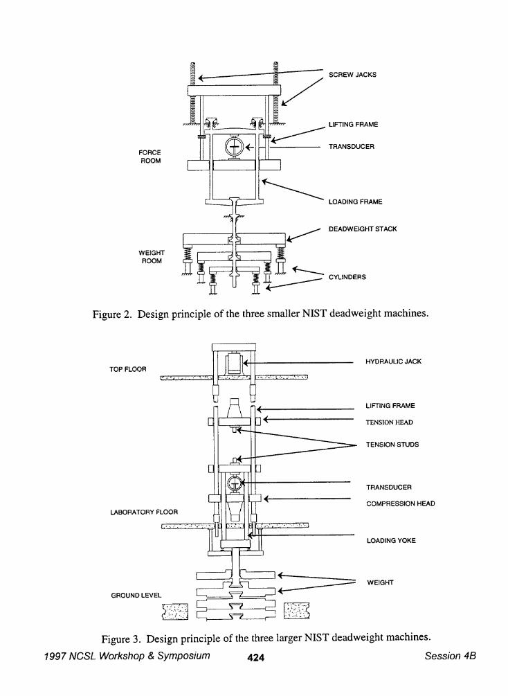
chosen because of its well-known long-term stability, machinability and availability. Moreover,the working mass standards used by the NIST Mass Group to calibrate the deadweights are alsomade of stainless steel. Therefore, the errors associated with air buoyancy adjustments areminimized. The particular alloy used for each deadweight machine is listed in Table 1. The designprinciples involved in the three smallest deadweight machines are shown in Figure 2 while the designof the larger machines are shown in Figure 3.
Today all NIST deadweight machines are able to apply forces in ascending and descendingfashion. Originally, actuation of the deadweight of the 113 kN and 2.2 kN deadweight machineswas such that the weight frame needed to be unloaded from the device under test, permitting onlyreturn-to-zero loading sequences. During the automation of the force facility, this limitation was
overcome by installing pneumatically operated stabilizing mechanisms on these two machines,enabling their deadweights to be changed while the frame is loaded without incurring eitherexcessive wear on the deadweight seats or swinging of the weight frame. These mechanismsretract from the weight frame shafts after each deadweight change. Ascending and descendingforce sequences can now be applied in these machines.
1997 NCSL Workshop & Symposium 423 Session 4B
)-f===b SCREW JACKS
FORCEROOM
WEIGHTROOM
AL AA
Figure 2. Design principle of the three smaller NIST deadweight machines.
I I
‘rI
TOP FLOOR
+
. . . . . . . . . . .
LABORATORY FLOOR?
LIFflNG FRAME
TRANSDUCER
LOADING FRAME
DEADWEIGHT STACK
CYLINDERS
n
HYDRAULIC JACK
~fl
~ “m’NG‘RAME
TRANSDUCER
COMPRESSION HEAD
LOADING YOKE
GROUND LEVEL
B
-
a
.-., , .-
D
.. ., .. .... ... ... .. ,.~...,>,... - .
,:. ... .. ... .... . ..... .. . .
WEIGHT
Figure 3. Design principle of the three larger NIST deadweight machines.
1997 NCSL Workshop & Symposium 424 Session 46

With theexception of the27kN (6.1 klbf)machine, the NISTdeadweight machines are now fullyautomated. Further, except for the 27 kN and the 4.448 MN machines, all are equipped withenvironmental chambers to allow NTEP and OIML testing.
2.2 kN (505 lbf) deadweight machineAir-powered cylinders manipulate lifting bars that allow the individual deadweights to be applied orremoved from the main shaft of the machine at any time during the measurement.
27 kN (6.1 klbf) deadweight machine
Hydraulic cylinders raise and lower deadweights individually onto the main shaft usually only whilethe machine is in the unloaded position. When the required deadweight complement is selected, themain shaft is positioned to allow force application to the unit under test. Limited ascending anddescending loading is possible in this machine under special circumstances. A unique feature of thisdeadweight machine is that nominal metric forces can be applied by activating an auxiliruydeadweight set. This deadweight machine is operated manually.
113 kN (25.3 klbf) deadwei~ht machineThe deadweight positioning system consists of a pair of hydraulic cylinders for each deadweight.These cylinders allow application or removal of every deadweight to the main shaft at any time. Amanually placed set of auxiliary metric conversion deadweights is available for this machine whichproduces nominal forces in 4.903 kN increments up to 107.873 kN. These conversion deadweightare used only in non automated measurements.
498 kN (112 klbf) deadweight machineCalibration forces are generated in this machine by serially applying deadweights from two differentstacks. The minimum force is 13.3 kN (3000 lb~ which consists of the calibrated frame and mainshaft of the machine and is always included as the first applied force. All other applied forces mustbe added to this minimum. The main stack consists of ten 44.4 kN (10,000 lbf) deadweights. ‘Thesecond stack consists of nine 4.44 kN (1,000 lbf) deadweights. The deadweights are removed oradded to the minimum 13.3 kN (3,000 Ibf) frame in increments of 4.44 kN (1000 lbf). Anexamination of the available deadweight combinations reveals that in some cases it is necessary tounload part of the small stack in order to reach a particular ascending force without first overshooting11.
1.33 MN (300,000 Ibfl deadweight machineAll deadweights in this machine are applied sequentially with no further individual manipulationpossible. The deadweights are of three different sizes. There are thirteen 44 kN (10 klbf)
deadweights, four 89 kN (20 klbf) deadweights and three 133 kN (30 klbf) deadweights. Thisarrangement allows the sequential calibration in ten equally spaced increments of nominal 444 kN(100 klbf), 890 kN (200 klbf), and 1.33 MN (300 klbf) force transducers.
1997 NCSL Workshop & Symposium 425 Session 4B
4.45 MN (1,000,000 lbf) deadweight machineThis deadweight machine simply applies twenty 222~(50,0Wlb~ forces sequentially. The mainlifting frame raises hydraulicdly topickup additional deadweights in the stack. This machine hasbeen fully automated.
3. Instrumentation
3.1. Deadweight Machine Control Instrumentation
Except for the 27 kN deadweight machine, all the NIST deadweight machines have beeninstrumented for automated control. With the exception of the mounting and positioning of the forcesensor into the deadweight machine, all machine operations can be done under computer control.Details of the automation have been described in reference 7.
A force measurement system has two components: a sensing component, normally called atransducer, and an indicating component, called an indicator. For example, if the transducer is aconventional proving ring, the response of the transducer, that is the change in diameter as the ringdistorts under an applied force, is indicated by a vibrating reed and a spherical button mounted cm theend of a micrometer. For conventional load cells, the change in strain at one or more points alongthe surface of the sensing element is indicated by a change in the output signal relative to the vc)ltageapplied to the load cell bridge. Only the reading of load cell indicators has been automated.Accordingly, measurements on proving rings are performed manually while measurements of mostload cells are performed automatically.
The benefits to be derived from the automation implemented in the force group are numerous. Theyinclude the ability to perform measurements with complex loading sequences, precise control of theloading time intervals, and more consistent indicator readings. In addition, in contrast to calibrations,the NTEP and OIML type evaluation tests require positioning of the load cell in the deadweightmachine only once, at the beginning of a test. The associated equipment required for these tests havealso been automated. Thus, the thermal bath units used to heat and cool the environmental chambersand the sensors used to monitor conditions, including the temperature of the load cell, are also undercomputer control. Thus, the tests, which typically take several days, can be conducted around theclock without any manual intervention.
3.2. Voltage Ratio Instrumentation
The force applied to a load cell produces a change in the resistive unbalance in the load cell straingage bfidge. For most load cellmeasurements performed at NIST, this resistive bridge unbalance is
measured with a calibrated NIST voltage-ratio indicating system.
The NIST indicating system supplies direct current excitation to the load cell, through the use of aspecially built power supply which applies DC voltages to the load cell excitation input leads of +5 Vrelative to the load cell ground wire, yielding 10 V difference between the leads. This excitationvoltage is stable to within ~ 5 ~V over a time period of 15 s. This power supply was designed to
switch internally the wires going to the load cell terminals by means of a computer command, thusreversing the polarity of the excitation signal to the load cell. This action makes it possible to cancel
1997 NCSL Workshop & Symposium 426 Session 4B
out small thermal biases in the strain gage bridge and connecting wires, as well as any zero offsets inthe rest of the indicating system. The switching is not done if the load cell is not designed toaccommodate reversed polarity excitation.
The excitation voltage and the load cell output voltage are sampled simultaneously by an 8’Iz digitcomputing voltmeter operating in voltage-ratio mode; the voltmeter calculates the correspondingvoltage ratio internally and returns that value in digital form to the computer. The voltmeter is readtwice, with the excitation voltage polarity reversed between readings; the final voltage ratio is takenas the average of the voltage ratios measured at each polarity. The sampling time at each polarity,and the delay after switching polarity before resuming the sampling, are specified by the operatorthrough the computer control/acquisition program. A typical time for one complete voltage ratioreading is 10s. This time can be shortened or lengthened as appropriate for the measurement beingconducted.
Calibration of the voltmeters in voltage-ratio mode is done by providing calibrated DC voltagesibgals simultaneous y to both inputs, with the DC calibrated signals derived from a 10 V Josephson-Junction reference voltage array maintained by the Electricity Division of the NIST Electronics andElectricity Engineering Laboratory. The NIST Electricity Division calibrates the Force Groupvoltmeters each year. The Force Group maintains the calibration of all of its voltmeters by monthlycomparison with the voltmeters most recently calibrated by the Electricity Division, through the useof two devices: a precision voltage reference divider having a 100:1 ratio and a load cell simulatorthat is stable to within+ 5 nV/V over a 24-hour time interval.
4. Measurement Uncertainty
4.1 Uncertainty in the Applied Force
In 1965 when the NIST deadweight machines were designed and built, a decision was made to adjustthe deadweight to exert standard pounds force, the standard pound force being defined as the forceacting on a one-pound mass under the influence of a gravity field of 9.80665 rn/s2. Deadweightswere adjusted for the local values of the gravitational acceleration and air density at the NISTGaithersburg site to generate a standard pound force given by:
F=9flo:65(l-~ , (1)
where I’ is the generated standard pound force, m is the mass of the weight, g is the local
acceleration due to gravity at the elevation of the center of gravity of the weight, Pu is the ~r density>and PWis the density of the weight. The uncertainties in the determination of m, /)a, and g are theprincipal sources of uncertainty in the applied force.
The mass of the deadweights of the NIST machines were determined by the NIST Mass Group.These calibrations were performed in 1965 prior to the assembly of the deadweights into themachines. Over the years, some of the deadweights were re-ca.librated. The 498 lcN deadweightmachine was partially disassembled in 1971 and 1989, with some of its deadweights removed and re-calibrated each time. The 2.2 kN machine was completely refurbished in 1996, and all of its
f997 NCSL Workshop & Symposium 427 Session 4B

deadweights were re-calibrated at that time. No significant changes in the mass of the deadweightswere detectable in either machine, confirming the long-term stability of the stainless steel alloys usedin the construction of both the smaller and larger NIST deadweight machines.
For each of the larger machines, the values of gravity were estimated at the approximate center ofgravity of the major components and at the center of gravity of the deadweight stacks. The gravityreference is located on the concrete slab of the first floor of the building where the deadweightmachines are located. The assigned absolute value of free-fall acceleration of gravit at this location
Lis 9.801018 m/s2, and is based upon an absolute determination conducted by Tate in 1965. Allother gravity values were based upon a gravity gradient of -0.000003/s2. A subsequent gravitysurvey at several positions within the force laboratory done by the Office of Ocean and EarthSciences of the National Oceanic and Atmospheric Administration in September 1991 confirmed theresults obtained in 1965.
The air density at the Gaithersburg site varies over a range of 1.145 kg/m3 to 1.226 kg/m3 throughoutthe year. In 1965, when the facility was built a decision was made to use an average value of airdensity equal to 1.185 kg/ m3”
The standard uncertainty in the force applied by the NIST deadweight machines incorporates theuncertainties associated with the determination of the mass of the deadweights, the accelerationto gravity and the air density as follows:
(a) The uncertainty in the determination of the mass of the deadweights is u~~ s 0.0003 %.
due
(b) The maximum error caused by the use of an average air density is the largest systematic errorin the applied force and is equal to 0.0005 %. The estimated standard deviation, assuming arectangular probability distribution, is Uwb = 0.0003 Yo.
(c) The estimated standard deviation associated with the variation in gravitational accelerationwith height, assuming a rectangular probability distribution, is uWC= 0.0001 70.
The standard uncertainty in the applied force is computed as:
Using the valuesUw= 0.0005 %.
JUw = uwa2 + uw~2 + UWC2. (2)
listed in (a), (b) and (c) above yields a standard uncertainty in the applied force
4.2 Uncertainty in Voltage Ratio Measurement
The standard uncertainty associated with the digital voltmeters used by the NIST Force Group forvoltage-ratio measurement incorporates the following:
(a) the uncertainty in calibration of the voltage-ratio of the voltmeters as determined by the NISTElectricity Division using a Josephson-Junction voltage array as a primary standard; the
1997 NCSL Workshop & Symposium 428 Session 4B

(b)
(c)
(d)
standard uncertainty in the voltage ratio over the range from 1 mV/V to 10 mV/V isU“a<0.0002 70.
differences between voltmeter calibrations performed by the NIST Electricity Division andcomparisons to a 10 mV/V reference ratio obtained with a precision reference divider useci bythe Force Group to track the voltmeter drift. The estimated standard deviation of thesedifferences assuming a rectangular probability distribution is Uvb = 0.0003 %.
the repeatability in measurements for each voltmeter (made at one-month intervals) of the10 mV/V response relative to the precision reference divideq the standard deviation for anindividual voltmeter is u,. = 0.0003940 of the reference ratio.
the nonlinearity in the voltage-ratio measurement response of the voltmeters in the range of1 mV/V to 10 mV/V; the estimated standard deviation based on Electricity Division dataassuming a rectangular probability distribution is Uvd = 0.0001 % of the reference ratio.
The standard uncertainty in the voltage-ratio instrument is given by:
JUv = UV=2+uvb2 + UVC2 +uvd2 . (3)
Applying the values given above yields a standard uncertainty for the voltage ratio uv = 0.0005 Yo.
4.3 Uncertainty in the Calibration Data
The calibration data acquired for a force sensor consists of the values of the forces applied to thesensor and the associated readings of the indicating system. These data usually incorporate two orthree orientations of the sensor in the deadweight machine. To obtain the actual deflection, theindicator reading observed during the force application is corrected for the reading observed withoutany force application. The calibration equation is derived by fitting a polynomial to the data usingthe method of least squares. The calibration curve is of the from:
(4)
where D is the deflection, F is the applied force, Ai are the coefficients yielded by the least-squaresfit, and the summation is generally carried to an order of 2 or 3.
ASTM E 74-95 standard specifies a standard deviation that is calculated from the differencesbetween the values observed during the course of calibration and the corresponding values computedfrom the calibration curve. This standard deviation is given by:
/
Zdj2
‘= (n-m) ‘(5)
where s is the standard deviation, the dj are the differences between the measured and calculateddeflections, n is the number of measured deflections, and rn is the number of degrees of freedom in
1997 NCSL Workshop & Symposium 429 Session 4B
the polynomial, the degree of the polynomial plus one. This standard deviation is one of the termsused in estimating the combined uncertainty as reported in the NIST calibration reports where it isdenoted as Ur.
The errors contained in u, are ordinarily much greater than the uncertainty in the applied load G. Thetwo major sources of systematic errors are mechanical misalignment and load-time effects. Inaddition, the response of the transducer is also dependent upon the loading sequence, the loading rate,the duration and stability of the load. A detailed statistical analysis that yields separate estimates ofuncertainty resulting from various sources of error can be found in reference.
The combined standard uncertainty stated in NIST force calibration reports is computed using thefollowing equation:
‘c=~ (6)
where UCis the combined standard uncertainty as defined in NIST Technical Note 12979, u~ is thestandard uncertainty in the applied deadweight forces (discussed in section 4.1), and u, is thestandard uncertainty in the calibration of the voltage-ratio measurement instrumentation (discussedin section 4.2), and u, is the standard deviation calculated accordingly to ASTM E 74-95. It shouldbe noted that the term u, applies only in calibrations involving voltage ratio measurementsperformed using the NIST voltmeters.
References
1.
2.
3.
4.
5.
6.
ASTM E 74-95, Standard Practice of Calibration of Force-Measuring Instruments forVerifying the Force Indication of Testing Machines, available from the American Society forTesting and Materials, Philadelphia, PA (1995).
National Conference on Weights and Measures, Publication 14, Section 2 - Chapter 3,Checklist for Load Cells (1994).
Organization Intemationale de M6trologie L&gale R 60, Metrological Regulation for LoadCells, Bureau International de Metrologies L6gale (1991).
NIST Handbook 44, Specifications, Tolerances, and Other Technical Requirements forWeighing and Measuring Devices, U.S. Department of Commerce, Gaithersburg, MD(1993).
S.L. Yaniv, A. Sawla, and M. Peters, Summary of the Intercomparison of the Force StandardMachines of the National Institute of Standards and Technology, USA, and the Physikalisch-
Technische Bundesanstalt, Germany, J. Res. Natl. Inst. Stand. Technol. 96,529-540 (1991).
R.A. Mitchell, Force Calibration at the National Bureau of Standards, NBS Technical Note1227, U.S. Department of Commerce, Gaithersburg, MD (1986).
1997 NCSL Workshop & Symposium 430 Session 46

7. K.W. Yee, Automation of Strain-Gauge Load-Cell Force Calibrations, Proc. 1992 Natl. Conf.of Stand. Lab. Workshop and Symposium, Washington, DC, p. 387-391, August 1992.
8. C.P. Reeve, A New Statistical Model for the Calibration of Force Sensors, NBSTechnical Note 1246, U.S. Department of Commerce, Gaithersburg, MD (1988).
9. B.N. Taylor and C.E. Kuyatt, Guidelines for Evaluating and Expressing the Uncertainty ofNIST Measurement Results, NIST Technical Note 1297, U.S. Department of Commerce,Gaithersburg, MD (1994).
10. D.R. Tate, Acceleration Due to Gravity at the National Bureau of Standards, NBSMonograph 107, U.S. Department of Commerce, Gaithersburg, MD (1968).
1997 IVCSL Workshop & Symposium 431 Session 4B