Focus on YOU - ProMinent
238
Volume 3/3 Focus on YOU Water Treatment and Disinfection Product catalogue 2021
-
Upload
khangminh22 -
Category
Documents
-
view
0 -
download
0
Transcript of Focus on YOU - ProMinent
Volume 3/3
Focus on YOU
Water Treatment and Disinfection Product catalogue 2021

Issued by:
ProMinent GmbH
Im Schuhmachergewann 5–11
69123 Heidelberg
Germany
Phone +49 6221 842–0
www.prominent.com
Technical changes reserved.
All previous catalogues and price lists are superseded with the release of this product catalogue.
You can view our general terms and conditions on our homepage.
Heidelberg, June 2021

1
Water treatment and water disinfectionOne-stop technology-independent solutions
Chapter 1
UV systems for gentle and chemical-free water treatment. They are ideal for the disinfection of municipal potable water or product water in the beverage industry. UV systems ensure swimming fun in perfectly clear water without undesired combined chlorine in swimming pool water treatment.
Ozone systems are the optimum solution if undesirable organic or inorganic substances need to be effectively removed. The reactive ozone provides efficient disinfection without the formation of by-products. It simply decomposes in water to form oxygen.
Electrolysis systems generate chlorine in a chemical-free manner on site from salt and electricity. There is therefore no need for the transport and storage of potentially hazardous chemicals and the chlorine products are produced just when they are needed. ProMinent electrolysis systems generate chlorine gas for swimming pool disinfection, hypochlorite for potable water treatment and hypochlorous acid for disinfection in the food industry.
Systems for chlorine gas metering DULCO® Vaq are particularly economical to run even with very high capacities. Vacuum technology means that chlorine gas systems are reliable and robust and are used glob-ally in potable water and in swimming pool water treatment.
Chlorine dioxide offers long-lasting microbiological protection, for instance of long pipework in potable wa-ter treatment. It can also be used in the most diverse applications in the food industry, for instance in bottle rinsers, process water, CIP (cleaning in place).
Chapter 2
Metering systems Ultromat® win customers over with their ease of assembly and operation. They meet very stringent requirements in terms of the separation of colloidal solids from liquids.
Storage tanks are indispensable. They comply with internationally applicable manufacturing approvals and are suitable for installation outdoors and indoors.
Chapter 3
Membrane systems are essential if particles or dissolved substances, such as salts, need to be removed from the water. Combined with the ProMinent product range, you can source complete water treatment solutions from a single supplier.
We’re there for youChoosing a product depends on a very wide range of factors.
Our team will be happy to be of assistance should you have any questions about our metering technology. Give us a call! We look forward to hearing from you.
Monday to Friday 8:00 am – 4:30 pmProMinent Germany Sales 0049 6221 842 - 1800 [email protected] consulting 0049 6221 842 - 1850 [email protected]
We can also support you by phone when selecting the right products and, in many cases, opti-mising entire applications. With more complex requirements, our consultants will hand the task over to a field sales colleague, who will then clarify your requirements in person on site.
After-sales service
Our service technicians are on hand to help you. Whether for the initial installation or maintenance and repair work. We’re happy to help!
0049 6221 842–1850 [email protected]
Product Catalogue Volume 3
01.06.2021 Product Catalogue Volume 3
2
Water treatment and water disinfection Page
1 Disinfection Systems and Oxidation Systems 131.1 UV Systems Dulcodes 13
1.1.1 General Notes on UV Treatment 131.1.2 Performance Overview of Dulcodes UV
Systems16
1.1.3 Questionnaire for Designing a UV System 181.1.4 UV System Dulcodes LP 191.1.5 UV System Dulcodes LP certified 231.1.6 UV system Dulcodes LP F&B 261.1.7 UV System Dulcodes LP-PE 281.1.8 UV System Dulcodes MP 301.1.9 UV System Dulcodes A 321.1.10 Accessories for Dulcodes UV Systems 351.1.11 DULCONNEX – digital fluid management 38
1.2 Ozone systems OZONFILT® and DULCOZON® 391.2.1 Ozone in Water Treatment 391.2.2 Performance Overview of Ozone Systems 401.2.3 Questionnaire on the Design of an Ozone
System41
1.2.4 Ozone System OZONFILT® OZVb 421.2.5 System Solution OZONFILT® Compact
OMVb47
1.2.6 Ozone System OZONFILT® OZMa 491.2.7 Ozone system DULCOZON® OZLa 561.2.8 Accessories and Spare Parts for Ozone
Systems60
1.2.8.1 Room Air Monitoring 651.2.9 Personal Protection Accessories 67
1.3 Bello Zon® Chlorine Dioxide Systems 681.3.1 Chlorine Dioxide in Water Treatment 681.3.2 Performance Overview of Chlorine Dioxide
Systems70
1.3.3 Questionnaire on the Design of a Chlorine Dioxide System
71
1.3.4 Chlorine Dioxide System Bello Zon® CDLb 721.3.5 Chlorine dioxide system Bello Zon® CDLb
H2SO4
74
1.3.6 Chlorine Dioxide System Bello Zon® CDLb with Multiple Points of Injection
81
1.3.7 Chlorine Dioxide System Bello Zon® CDEb 821.3.8 Chlorine Dioxide System Bello Zon® CDVd 841.3.9 Chlorine Dioxide System Bello Zon® CDKd 891.3.10 Storage Tank Accessories 941.3.11 Bypass Line Accessories 951.3.12 Chemical Supply Accessories 981.3.13 Safety Accessories and Analysis 1011.3.14 DULCONNEX - digital fluid management 105
1.4 Electrolysis systems CHLORINSITU and DULCO®Lyse 106
Table of contents
01.06.2021Product Catalogue Volume 3
3
1.4.1 Electrolysis Systems CHLORINSITU 1061.4.2 Performance Overview 1071.4.3 Questionnaire on the design of an electrolysis
plant109
1.4.4 Electrolysis System CHLORINSITU IIa 60 – 2,500 g/h
110
1.4.5 Electrolysis System CHLORINSITU III 1151.4.6 Electrolysis systems CHLORINSITU® III
Compact and IV Compact117
1.4.7 Electrolysis System CHLORINSITU® IV Compact
119
1.4.8 Electrolysis system CHLORINSITU® V 1211.4.9 Electrolysis system CHLORINSITU® V Plus 1231.4.10 Questionnaire on the Design of a
DULCO®Lyse Electrolysis System126
1.4.11 Electrolysis System DULCO®Lyse 1271.5 Chlorine Gas Metering Systems DULCO®Vaq 131
1.5.1 General Information on Chlorine Gas Metering Systems
131
1.5.2 Performance Overview of Chlorine Gas Metering Systems DULCO®Vaq
132
1.5.3 Questionnaire on the Design of a Chlorine Gas Metering System
133
1.5.4 Vacuum controller for chlorine gas DULCO®Vaq
134
1.5.5 Motor-Driven Control Valve for Chlorine Gas DULCO®Vaq
139
1.5.6 Manual Chlorine Gas Metering Unit DULCO®Vaq PM3720 C
141
1.5.7 Automatic Chlorine Gas Metering System DULCO®Vaq
142
1.5.8 Chlorine Gas Metering System DULCO®Vaq 1441.5.9 Vacuum Switch-Over for Chlorine Gas
DULCO®Vaq146
1.5.10 Pressure Switch-Over for Chlorine Gas DULCO®Vaq
148
1.5.11 Injector for Chlorine Gas DULCO®Vaq 1491.5.12 Flow Meter for Chlorine Gas DULCO®Vaq 1511.5.13 Automatic Emergency Shut-Off System for
Chlorine Gas DULCO®Vaq152
1.5.14 Evaporator for Chlorine Gas DULCO®Vaq 1541.5.15 Neutraliser for Chlorine Gas DULCO®Vaq 1551.5.16 Accessories for Chlorine Gas Metering 1561.5.17 Accessories for Room and Safety Equipment 1601.5.18 Other Accessories 1631.5.19 Personal Safety Equipment 165
2 Metering Systems 1672.1 Polymer Preparation and Metering Systems 167
2.1.1 Polyelectrolytes in Water Treatment 167
Water treatment and water disinfection Page
Table of contents
01.06.2021 Product Catalogue Volume 3

4
2.1.2 Performance overview of polymer batching and metering systems Ultromat® and PolyRex
168
2.1.3 Questionnaire for the design of polymer batching and metering systems Ultromat® and PolyRex
169
2.1.4 Preparation stations and metering of powdered and liquid polymer solutions Ultromat®
170
2.1.5 Metering System Ultromat® ULFa 1712.1.6 Metering System Ultromat® ULPa 1762.1.7 Metering System Ultromat® ULDa 1802.1.8 Metering System Ultromat® ULIa (Inline
System Liquid)185
2.1.9 Metering System Ultromat® MT for Batch Operation
189
2.1.10 Ultromat® Accessories including Big Bag Systems
191
2.1.11 Batching stations and metering of powdered and liquid polymer solutions PolyRex
194
2.1.12 Metering System PolyRex 1952.1.13 Metering System PolyRex Big Bag 1982.1.14 Metering System PolyRex Liquid 2012.1.15 PolyRex Accessories – Mixing Systems 2032.1.16 TOMAL® multi-screw feeder 204
2.2 Metering and emptying station DULCODOS® SAFE-IBC
205
2.2.1 Metering and emptying station DULCODOS® SAFE-IBC
205
2.3 Storage and process tanks 2082.3.1 PE/PP storage tank, general 2082.3.2 PE Storage Tank With General WHG
Approval209
2.3.3 Accessories according to the specifications of the Federal Water Act (WHG) and/or the Ordinance on installations for the handling of substances hazardous to water (VAwS)
212
2.3.4 Other Accessories 2142.3.5 PP/PE process storage tank, customised 215
3 Filtration 2173.1 Overview of Membrane Technology 2173.2 Ultrafiltration Systems 218
3.2.1 Performance Overview of Ultrafiltration 2183.2.2 Questionnaire on the Design of a UF System 2203.2.3 Ultrafiltration Systems Dulcoclean® UF 221
3.3 Nanofiltration Systems 2223.3.1 Nanofiltration System Dulcosmose® NF 222
3.4 Reverse Osmosis Systems 2243.4.1 Performance Overview of Reverse Osmosis 2243.4.2 Questionnaire on the Design of an RO
System226
3.4.3 Reverse Osmosis System Dulcosmose® TW 227
Water treatment and water disinfection Page
Table of contents
01.06.2021Product Catalogue Volume 3
5
3.4.4 Reverse Osmosis System Dulcosmose® BW 2293.4.5 Reverse Osmosis System Dulcosmose® SW 231
3.5 Gravity Filters 2333.5.1 Sand filter INTERFILT SK 233
Water treatment and water disinfection Page
Table of contents
01.06.2021 Product Catalogue Volume 3
6
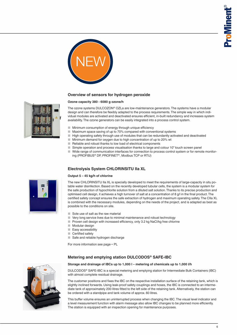
Overview of sensors for hydrogen peroxideOzone capacity 380 - 6080 g ozone/h
The ozone systems DULCOZON® OZLa are low-maintenance generators. The systems have a modular design and can therefore be flexibly adapted to the process requirements. The simple way in which indi-vidual modules are activated and deactivated ensures efficient, in-built redundancy and increases system availability. The ozone generators can be easily integrated into a process control system.
■ Minimum consumption of energy through unique efficiency ■ Maximum space saving of up to 70% compared with conventional systems ■ High operating safety through use of modules that can be redundantly activated and deactivated ■ Minimum demand for oxygen due to high concentration of up to 20% wt ■ Reliable and robust thanks to low load of electrical components ■ Simple operation and process visualisation thanks to large and colour 10” touch screen panel ■ Wide range of communication interfaces for connection to process control system or for remote monitor-
ing (PROFIBUS® DP, PROFINET®, Modbus TCP or RTU)
Electrolysis System CHLORINSITU IIa XLOutput 5 – 45 kg/h of chlorine
The new CHLORINSITU IIa XL is specially developed to meet the requirements of large-capacity in situ po-table water disinfection. Based on the recently developed tubular cells, the system is a modular system for the safe production of hypochlorite solution from a diluted salt solution. Thanks to its precise production and optimised cell design, it achieves a high turnover of salt at a concentration of 8 g/l in the final product. The certified safety concept ensures the safe extraction of hydrogen and maximum operating safety. The CIIa XL is combined with the necessary modules, depending on the needs of the project, and is adapted as best as possible to the conditions on site.
■ Sole use of salt as the raw material ■ Very long service lives due to minimal maintenance and robust technology ■ Proven cell design with increased efficiency, only 3.2 kg NaCl/kg free chlorine ■ Modular design ■ Easy accessibility ■ Certified safety ■ Safe and reliable hydrogen discharge
For more information see page→ PL
Metering and emptying station DULCODOS® SAFE-IBCStorage and drainage of IBCs up to 1,000 l – metering of chemicals up to 1,000 l/h
DULCODOS® SAFE-IBC is a special metering and emptying station for Intermediate Bulk Containers (IBC) with almost complete residual drainage.
The customer positions and fixes the IBC on the respective installation surface of the retaining tank, which is slightly inclined forwards. Using leak-proof safety couplings and hoses, the IBC is connected to an interme-diate tank of approximately 200 litres fitted to the left side of the retaining tank. Alternatively, the station can be ordered with a standpipe and tank volume of approx. 60 litres.
This buffer volume ensures an uninterrupted process when changing the IBC. The visual level indicator and a level measurement function with alarm message also allow IBC changes to be planned more efficiently. The station is equipped with an inspection opening for maintenance purposes.
7
To ensure reliable metering, a compact metering station can be integrated in the front of the intermediate tank depending on process requirements. This is equipped either with one or two solenoid metering pumps or with one motor-driven metering pump.
Larger metering stations can be configured as required and designed for side mounting on the wall or instal-lation on the floor.
■ Maximum operating safety. ■ Excellent process reliability due to interruption-free metering in the process. ■ Secure installation of an IBC on a special roll-under retaining tank construction. Any drops are reliably
collected and cannot escape at the installation site. ■ Almost complete residual drainage of the IBC. ■ Intermediate tank with a volume of approx. 200 litres combined with an integrated metering station. ■ Retaining tank and intermediate tank both have DIBt approval Z-40.21-585. ■ Special designs for installation in earthquake zones 1 to 3 in accordance with DIN 4149.
For more information see page→ PL
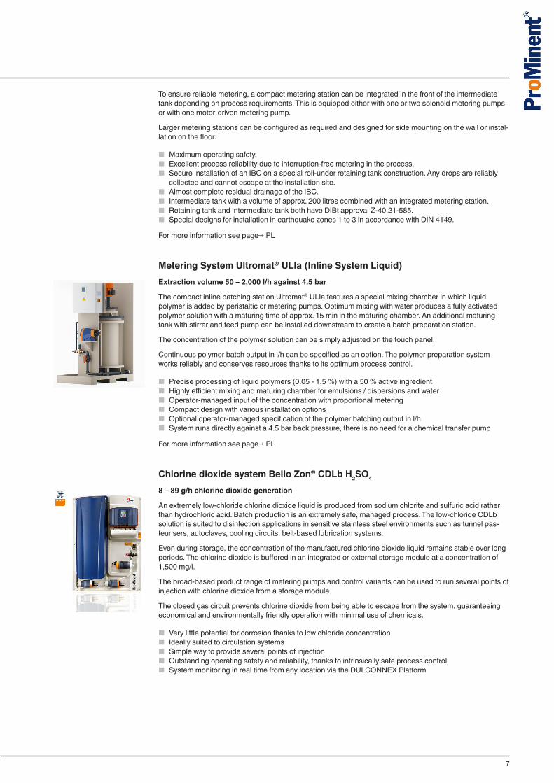
Metering System Ultromat® ULIa (Inline System Liquid)Extraction volume 50 – 2,000 l/h against 4.5 bar
The compact inline batching station Ultromat® ULIa features a special mixing chamber in which liquid polymer is added by peristaltic or metering pumps. Optimum mixing with water produces a fully activated polymer solution with a maturing time of approx. 15 min in the maturing chamber. An additional maturing tank with stirrer and feed pump can be installed downstream to create a batch preparation station.
The concentration of the polymer solution can be simply adjusted on the touch panel.
Continuous polymer batch output in l/h can be specified as an option. The polymer preparation system works reliably and conserves resources thanks to its optimum process control.
■ Precise processing of liquid polymers (0.05 - 1.5 %) with a 50 % active ingredient ■ Highly efficient mixing and maturing chamber for emulsions / dispersions and water ■ Operator-managed input of the concentration with proportional metering ■ Compact design with various installation options ■ Optional operator-managed specification of the polymer batching output in l/h ■ System runs directly against a 4.5 bar back pressure, there is no need for a chemical transfer pump
For more information see page→ PL
Chlorine dioxide system Bello Zon® CDLb H2SO4
8 – 89 g/h chlorine dioxide generation
An extremely low-chloride chlorine dioxide liquid is produced from sodium chlorite and sulfuric acid rather than hydrochloric acid. Batch production is an extremely safe, managed process. The low-chloride CDLb solution is suited to disinfection applications in sensitive stainless steel environments such as tunnel pas-teurisers, autoclaves, cooling circuits, belt-based lubrication systems.
Even during storage, the concentration of the manufactured chlorine dioxide liquid remains stable over long periods. The chlorine dioxide is buffered in an integrated or external storage module at a concentration of 1,500 mg/l.
The broad-based product range of metering pumps and control variants can be used to run several points of injection with chlorine dioxide from a storage module.
The closed gas circuit prevents chlorine dioxide from being able to escape from the system, guaranteeing economical and environmentally friendly operation with minimal use of chemicals.
■ Very little potential for corrosion thanks to low chloride concentration ■ Ideally suited to circulation systems ■ Simple way to provide several points of injection ■ Outstanding operating safety and reliability, thanks to intrinsically safe process control ■ System monitoring in real time from any location via the DULCONNEX Platform

8
DULCONNEX - the total solution for your digital fluid managementProMinent’s DULCONNEX is the smart overall solution for digitally networking your system components. The DULCONNEX is based on robustly networked products that can be individually adapted to operat-ing conditions. As all the components of a system are networked, metering pumps, disinfection systems, controllers and sensors can interact in an optimised manner – increasing process reliability and system efficiency.
Location-independent system monitoring in real time
With DULCONNEX, you always have access to all key data and measured values for your installations. Monitor the status of your system in real time and benefit from continuous documentation. Check your device data safely and reliably when you’re out and about. Simply use the terminal device of your choice: smartphone, tablet or PC. Configurable alarms and messages inform you of relevant events 24/7.
Be in a position to act promptly at all times with DULCONNEX. Whether potable water, waste water, indus-trial and process water, cooling water or swimming pool water – DULCONNEX supports you in ensuring the reliable treatment of your fluids.
9
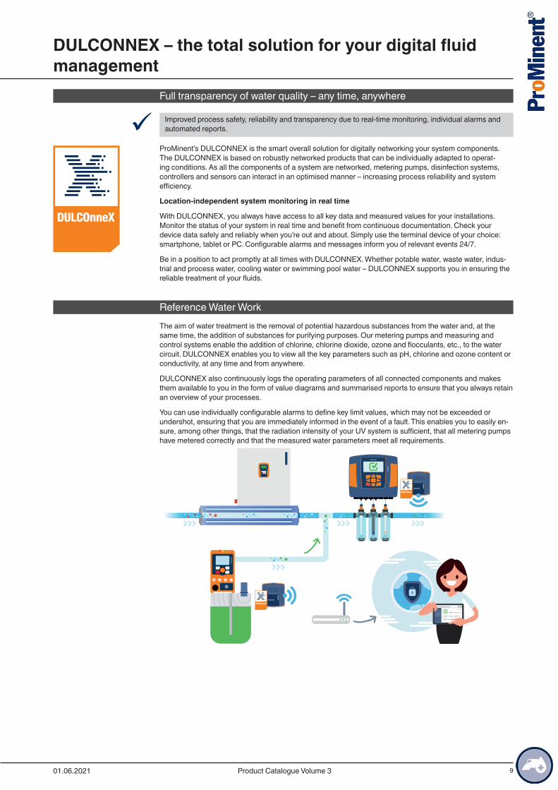
Full transparency of water quality – any time, anywhere
9 Improved process safety, reliability and transparency due to real-time monitoring, individual alarms and automated reports.
ProMinent’s DULCONNEX is the smart overall solution for digitally networking your system components. The DULCONNEX is based on robustly networked products that can be individually adapted to operat-ing conditions. As all the components of a system are networked, metering pumps, disinfection systems, controllers and sensors can interact in an optimised manner – increasing process reliability and system efficiency.
Location-independent system monitoring in real time
With DULCONNEX, you always have access to all key data and measured values for your installations. Monitor the status of your system in real time and benefit from continuous documentation. Check your device data safely and reliably when you’re out and about. Simply use the terminal device of your choice: smartphone, tablet or PC. Configurable alarms and messages inform you of relevant events 24/7.
Be in a position to act promptly at all times with DULCONNEX. Whether potable water, waste water, indus-trial and process water, cooling water or swimming pool water – DULCONNEX supports you in ensuring the reliable treatment of your fluids.
Reference Water WorkThe aim of water treatment is the removal of potential hazardous substances from the water and, at the same time, the addition of substances for purifying purposes. Our metering pumps and measuring and control systems enable the addition of chlorine, chlorine dioxide, ozone and flocculants, etc., to the water circuit. DULCONNEX enables you to view all the key parameters such as pH, chlorine and ozone content or conductivity, at any time and from anywhere.
DULCONNEX also continuously logs the operating parameters of all connected components and makes them available to you in the form of value diagrams and summarised reports to ensure that you always retain an overview of your processes.
You can use individually configurable alarms to define key limit values, which may not be exceeded or undershot, ensuring that you are immediately informed in the event of a fault. This enables you to easily en-sure, among other things, that the radiation intensity of your UV system is sufficient, that all metering pumps have metered correctly and that the measured water parameters meet all requirements.
https://dulconnex.prominent.com
DULCONNEX – the total solution for your digital fluid management
01.06.2021 Product Catalogue Volume 3
10
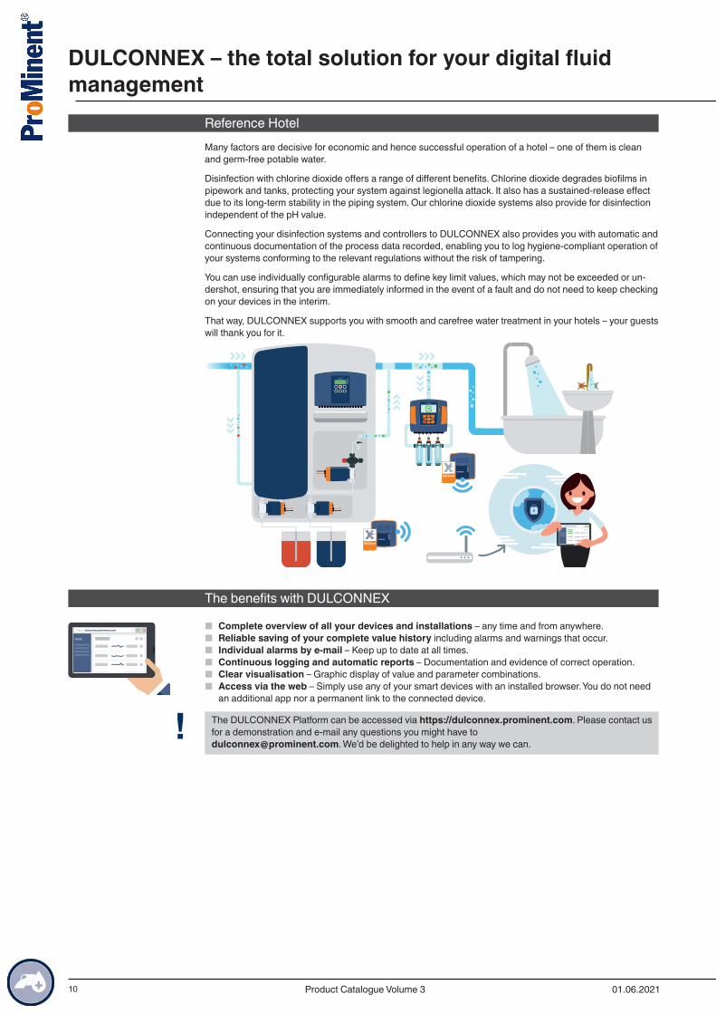
Reference HotelMany factors are decisive for economic and hence successful operation of a hotel – one of them is clean and germ-free potable water.
Disinfection with chlorine dioxide offers a range of different benefits. Chlorine dioxide degrades biofilms in pipework and tanks, protecting your system against legionella attack. It also has a sustained-release effect due to its long-term stability in the piping system. Our chlorine dioxide systems also provide for disinfection independent of the pH value.
Connecting your disinfection systems and controllers to DULCONNEX also provides you with automatic and continuous documentation of the process data recorded, enabling you to log hygiene-compliant operation of your systems conforming to the relevant regulations without the risk of tampering.
You can use individually configurable alarms to define key limit values, which may not be exceeded or un-dershot, ensuring that you are immediately informed in the event of a fault and do not need to keep checking on your devices in the interim.
That way, DULCONNEX supports you with smooth and carefree water treatment in your hotels – your guests will thank you for it.
https://dulconnex.prominent.com
The benefits with DULCONNEX
■ Complete overview of all your devices and installations – any time and from anywhere. ■ Reliable saving of your complete value history including alarms and warnings that occur. ■ Individual alarms by e-mail – Keep up to date at all times. ■ Continuous logging and automatic reports – Documentation and evidence of correct operation. ■ Clear visualisation – Graphic display of value and parameter combinations. ■ Access via the web – Simply use any of your smart devices with an installed browser. You do not need
an additional app nor a permanent link to the connected device.
! The DULCONNEX Platform can be accessed via https://dulconnex.prominent.com. Please contact us for a demonstration and e-mail any questions you might have to [email protected]. We’d be delighted to help in any way we can.
https://dulconnex.prominent.com
DULCONNEX – the total solution for your digital fluid management
01.06.2021Product Catalogue Volume 3
11
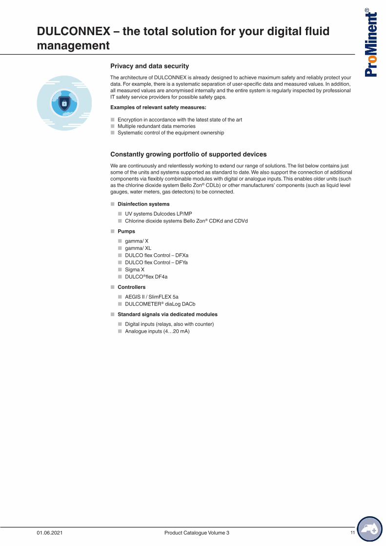
Privacy and data securityThe architecture of DULCONNEX is already designed to achieve maximum safety and reliably protect your data. For example, there is a systematic separation of user-specific data and measured values. In addition, all measured values are anonymised internally and the entire system is regularly inspected by professional IT safety service providers for possible safety gaps.
Examples of relevant safety measures:
■ Encryption in accordance with the latest state of the art ■ Multiple redundant data memories ■ Systematic control of the equipment ownership
Constantly growing portfolio of supported devicesWe are continuously and relentlessly working to extend our range of solutions. The list below contains just some of the units and systems supported as standard to date. We also support the connection of additional components via flexibly combinable modules with digital or analogue inputs. This enables older units (such as the chlorine dioxide system Bello Zon® CDLb) or other manufacturers’ components (such as liquid level gauges, water meters, gas detectors) to be connected.
■ Disinfection systems
■ UV systems Dulcodes LP/MP ■ Chlorine dioxide systems Bello Zon® CDKd and CDVd
■ Pumps
■ gamma/ X ■ gamma/ XL ■ DULCO flex Control – DFXa ■ DULCO flex Control – DFYa ■ Sigma X ■ DULCO®flex DF4a
■ Controllers
■ AEGIS II / SlimFLEX 5a ■ DULCOMETER® diaLog DACb
■ Standard signals via dedicated modules
■ Digital inputs (relays, also with counter) ■ Analogue inputs (4…20 mA)
DULCONNEX – the total solution for your digital fluid management
01.06.2021 Product Catalogue Volume 3
12
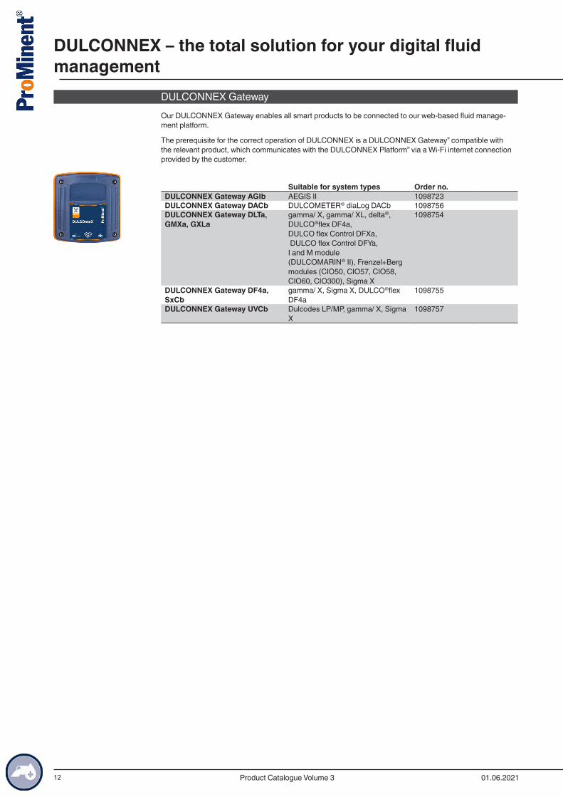
DULCONNEX GatewayOur DULCONNEX Gateway enables all smart products to be connected to our web-based fluid manage-ment platform.
The prerequisite for the correct operation of DULCONNEX is a DULCONNEX Gateway” compatible with the relevant product, which communicates with the DULCONNEX Platform” via a Wi-Fi internet connection provided by the customer.
Suitable for system types Order no.
DULCONNEX Gateway AGIb AEGIS II 1098723DULCONNEX Gateway DACb DULCOMETER® diaLog DACb 1098756DULCONNEX Gateway DLTa, GMXa, GXLa
gamma/ X, gamma/ XL, delta®, DULCO®flex DF4a, DULCO flex Control DFXa, DULCO flex Control DFYa, I and M module (DULCOMARIN® II), Frenzel+Berg modules (CIO50, CIO57, CIO58, CIO60, CIO300), Sigma X
1098754
DULCONNEX Gateway DF4a, SxCb
gamma/ X, Sigma X, DULCO®flex DF4a
1098755
DULCONNEX Gateway UVCb Dulcodes LP/MP, gamma/ X, Sigma X
1098757
DULCONNEX – the total solution for your digital fluid management
01.06.2021Product Catalogue Volume 3
13
1.1.1 General Notes on UV Treatment Disinfection is a key stage in modern water treatment. UV disinfection is used to an ever increasing extent as a safe, chemical-free and reliable disinfection process. Extensive research projects and numerous systems operating without any issues prove the safety and reliability of UV disinfection.
With UV disinfection, the water to be disinfected is irradiated with ultraviolet light. This is a purely physical, chemical-free process for water disinfection.
UV-C radiation in particular, with a wavelength ranging from 240 to 280 nm, attacks the vital DNA of the germs directly. The radiation initiates a photochemical reaction and destroys the genetic information contained in the DNA. The germs lose their reproduction capability and are destroyed. Even parasites, like Cryptosporidia or Giardia, which are extremely resistant to chemical disinfectants, are efficiently reduced.
Photochemical reactions are triggered in other applications too. For example, the undesirable use of com-bined chlorine in swimming pool water is reduced through UV radiation, resulting in enormous fresh water savings. Oxidants, such as ozone, chlorine or chlorine dioxide, are reliably reduced in the production water used in the food and pharmaceutical industry, avoiding the need for costly active carbon filters.
UV disinfection has many advantages:
■ Immediate and safe destruction of germs without the addition of chemicals ■ Photochemical reduction of undesirable substances ■ No THM or AOX formation, no formation of other undesirable substances ■ No impairment of the odour or taste of the water ■ No storage and handling of chemicals required ■ Effect is independent of the pH value ■ No reaction vessel or reaction tank required ■ Minimal space requirement ■ Low investment and operating costs with excellent reliability and efficiency
Applications of Dulcodes UV SystemsA large number of our UV disinfection systems have been supplied worldwide, for the most diverse of appli-cations:
■ Private water suppliers and municipal water works
■ for the disinfection of drinking water
■ Food and beverage industry
■ to destroy germs in the water needed for food and beverage production and for the disinfection of process water
■ for the reduction of chlorine dioxide, ozone or chlorine in product water ■ for the disinfection of sugar syrup
■ Pharmaceutical and cosmetics industry
■ to meet the high microbiological requirements of the production water ■ to destroy residual ozone in the production water without the use of active carbon filters
■ Reverse osmosis systems
■ for permeate disinfection
■ Horticulture
■ for the disinfection of irrigation water
■ Spa pools and swimming pools
■ for the disinfection of the pool water ■ for chloramine reduction in the pool water
Description of Dulcodes UV Systems
Dulcodes UV disinfection systems essentially consist of:
■ High-quality radiation chambers made of stainless steel (DIN 1.4404) or UV-resistant plastic ■ Lamp protection tubes made of high-quality quartz, easily removable for cleaning purposes ■ Lamps with an exceptionally high UV output in the 254 nm range ■ Highly selective UV sensors with good long-term and temperature stability ■ UV system controllers and modern electronic ballasts fitted in a control cabinet
1.1 UV Systems Dulcodes
01.06.2021 Product Catalogue Volume 3
Dis
infe
ctio
n Sy
stem
s an
d O
xida
tion
Syst
ems

14
The special features of our Dulcodes UV disinfection systems are:
■ Homogeneous UV dose distribution thanks to optimised flow behaviour in the reactor guarantees maxi-mum flow output with a minimum number of lamps and minimum pressure loss
■ Reduced life cycle costs due to the long service life of high-output lamps with low energy consumption and high UV yield
■ Unique active temperature management of Vario-Flux low-pressure technology adapts the lamp output in seconds and provides for optimum disinfection even with rapidly changing flows and temperature conditions
■ Efficient and chemical-free cleaning of the cover tubes with manual or automatic wiper system without interruption to operation
■ Continuous monitoring of the reactor temperature by temperature sensor Pt 1000 ■ Electronic ballasts for the gentle ignition and operation and individual monitoring of the lamps ■ Dulcodes LP control cabinet with efficient recirculation cooling ensures the long life of electronic compo-
nents and protects against corrosion in aggressive ambient conditions ■ Various options for simple integration of the system in higher-level control systems thanks to many ana-
logue and digital interfaces and connectors ■ User-friendly and intuitive control for displaying operating statuses and adjusting operating parameters ■ Comprehensive biodosimetric validation in line with EPA-UVDGM or DVGW and ÖVGW certification for
selected product ranges confirm disinfection efficiency
Dulcodes UV Lamps
Low-pressure lamp Vario-Flux
Newly developed and patented high-performance amalgam lamp with a guaranteed life expectancy of 14,000 operating hours (pro rata). The lamps are characterised by their high UV yield and minimal ageing behaviour. Thanks to the unique combination of electronic ballast technology and the Vario-Flux lamps, they can be controlled quickly and precisely over a broad capacity range of up to 50% of the nominal power. Sea-sonal fluctuations in water temperature are no longer an issue and are simply compensated for by the active temperature management of the lamp. Efficiency increases even in dimmed mode. This has a particularly positive effect when the actual flow is below the system’s maximum possible flow. The special technology also enables vertical and horizontal installation.
Medium-pressure lamp Powerline
Medium-pressure mercury lamp with a life expectancy of approx. 8,000 to 10,000 operating hours, depend-ing on the lamp size. The high output of these lamps permits the treatment of very large flows. Thanks to their broad range spectrum, these lamps are particularly suitable for photochemical processes. The operat-ing temperature of the lamps is 650 – 850 °C. The water temperature is therefore monitored and the system switches off when a limit temperature is exceeded.
1.1 UV Systems Dulcodes
01.06.2021Product Catalogue Volume 3
Dis
infe
ctio
n Sy
stem
s an
d O
xida
tion
Syst
ems
15
Dulcodes UV Controllers
Compact controller
Compact unit for controlling all the UV system’s functions. The controller can be selected for single lamp systems of the Dulcodes LP product range. The display alternately shows the current radiation intensity, the operating hours and the number of lamp switch-ons. The Compact controller informs the operator if values fall below freely programmable safety and warning thresholds. Different functions, such as commissioning flushing, interval flushing, idle flushing and a run-on time can be freely set to meet demand.
The controller has the following inputs and outputs:
■ Connection for both a flushing and shut-off valve (230 V) ■ Potential-free contact output for the end of lamp service life, power failure and warning ■ Potential-free changeover output for operating and common alarm messages ■ Potential-free contact input for temperature or flow control and pause ■ 4-20 mA standard signal output for sensor signal
Comfort controller UVCb
The Comfort controller consists of a control PCB and a remote display and control unit integrated in the door of the control cabinet. The UV systems are controlled in a user-friendly and intuitive manner. All operating statuses are shown on the display and all operating and fault messages are issued in plain text. The sys-tem’s operating status (Operation/Warning/Fault) can be seen from afar by means of LEDs.
The Comfort controller UVCb is connected to the electronic ballasts via a bus system so that each individ-ual lamp can be precisely monitored. Different cable lengths are detected automatically and the operating parameters adjusted accordingly. The interaction between the coordinated controller, electronic ballasts and UV lamp components enables the output of the low- and medium-pressure lamps to be adjusted to the water quality or water flow via an external 4-20 mA standard signal.
Various auxiliary functions, such as the automatic flushing of the system over a freely programmable flush-ing time, the control of a shut-off valve and a circulating pump are integrated as standard. The controller is responsible for controlling the automatic wiper system. During the wiping process, the position is checked a number of times for absolute operational safety of the wiper system. This is done by monitoring the end position and by continuous data exchanges between the wiper motor and controller.
The UVC sensor signal can be monitored online via a standard signal output 0/4-20 mA. Any transgressions of the warning threshold, minimum radiation strength and faults are reported via contact outputs. The reactor temperature is monitored by a temperature sensor to avoid the temperature being impermissibly exceeded.
Potential-free control inputs make it possible to connect to external higher-order systems: The “Pause” input can be used to regularly interrupt system operation, with the “External fault” contact input leading to the sys-tem being shut down in the event of a fault on a peripheral component connected externally. If the applica-tion requires different UV doses, a contact input can quickly adapt the UV dose to the changing requirement.
The Comfort controller UVCb features an operating diary. All events are saved on an SD card and can sim-ply be read off on a PC. The UV sensor signal and other measuring parameters, connected to the controller via external standard signals, are stored on the SD card at set time intervals.
The controller has the following inputs and outputs:
■ 3 switched voltage outputs for flushing and shut-off valve and feed pump (230 V or 24 V) ■ 3 potential-free contact outputs for warning, common alarm and operating messages ■ 4 potential-free contact inputs for pause, external fault, activate emergency mode, setpoint 1/2 switcho-
ver ■ 1 standard signal output 4-20 mA for sensor signal ■ 2 standard signal inputs 4-20 mA for flow and turbidity or combined chlorine with a limit value function ■ CAN-bus interface for integrating higher-level controls
Comfort controller Dulcodes A
A Siemens S7– 1200 controller with a KP 300 Basic operating panel is used to operate and control Dul-codes A systems. The functionality corresponds to that of the Comfort controller UVCb.
1.1 UV Systems Dulcodes
01.06.2021 Product Catalogue Volume 3
Dis
infe
ctio
n Sy
stem
s an
d O
xida
tion
Syst
ems

16
1.1.2 Performance Overview of Dulcodes UV SystemsProMinent offers a wide range of UV systems for the most diverse applications. The following overview shows the capacity and main applications of our standard systems:
certifiedTyp LP
Plastic chamberTyp MPConventional
ballast technologyElectronic
ballast technology
Typ LPF&B
Typ LP Typ LPnot certified
Type LP: Low pressure
Type MP: Medium pressure
ProMinent provides all the advice you need to safely operate a Dulcodes UV system:
■ Evaluation of the situation on site by trained, expert field sales staff. ■ Project planning of the system. ■ Commissioning and system maintenance by our trained service technicians.
1.1 UV Systems Dulcodes
01.06.2021Product Catalogue Volume 3
Dis
infe
ctio
n Sy
stem
s an
d O
xida
tion
Syst
ems
17
Notes on Planning and Designing an UV System
■ The system should always be designed for the maximum water flow. ■ The system should always be designed for the lowest expected UV transmission. ■ Provide valves for microbiological sampling upstream and downstream of UV disinfection systems. ■ Provide a manual shut-off valve upstream of the UV system to isolate the system for maintenance work. ■ Provide an electrically controlled shut-off valve downstream of the UV disinfection system for drinking
water disinfection and similar applications, which also closes automatically in the event of mains power failure (solenoid valve, automatic motor valve or similar).
■ With process water disinfection, it is normally sufficient to provide a manual valve to isolate the system for maintenance work, instead of an electrically controlled valve.
■ Provide a rinse valve downstream of UV disinfection with drinking water disinfection and similar applica-tions.
■ It must be ensured that there is sufficient space available for removing the lamp protection tube and lamp replacement.
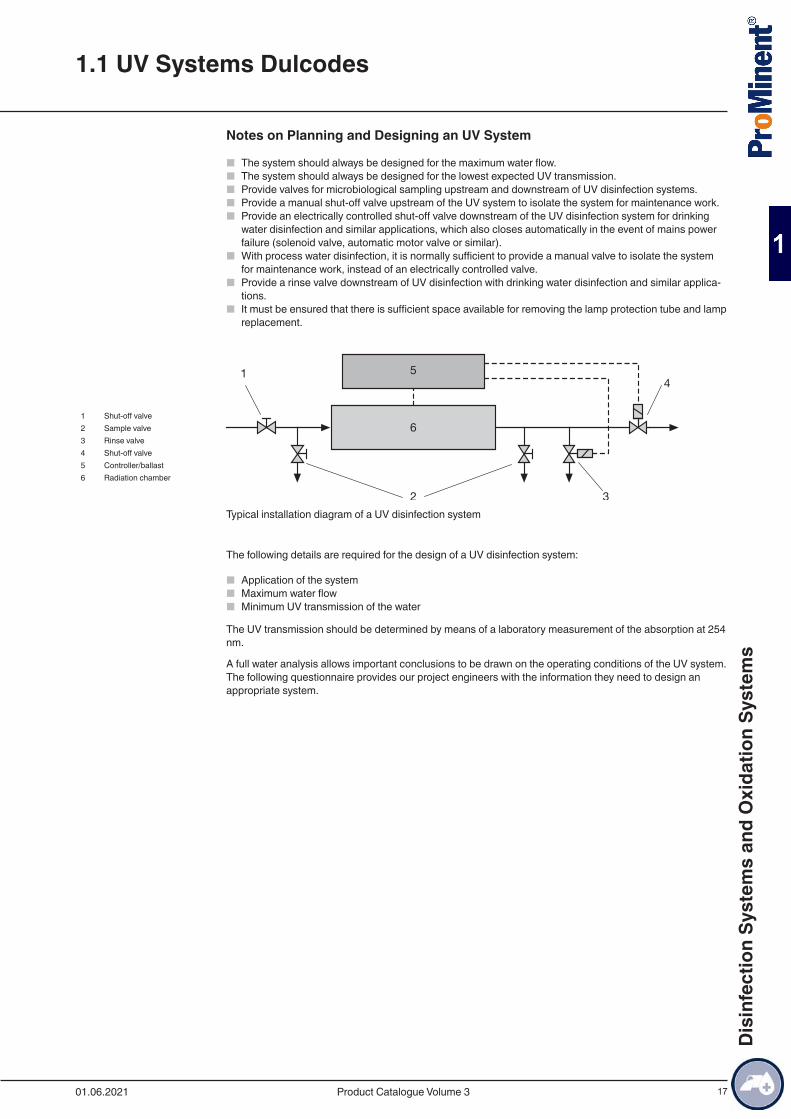
1 Shut-off valve2 Sample valve3 Rinse valve4 Shut-off valve5 Controller/ballast6 Radiation chamber
Typical installation diagram of a UV disinfection system
The following details are required for the design of a UV disinfection system:
■ Application of the system ■ Maximum water flow ■ Minimum UV transmission of the water
The UV transmission should be determined by means of a laboratory measurement of the absorption at 254 nm.
A full water analysis allows important conclusions to be drawn on the operating conditions of the UV system. The following questionnaire provides our project engineers with the information they need to design an appropriate system.
1.1 UV Systems Dulcodes
01.06.2021 Product Catalogue Volume 3
Dis
infe
ctio
n Sy
stem
s an
d O
xida
tion
Syst
ems
18
1.1.3 Questionnaire for Designing a UV System
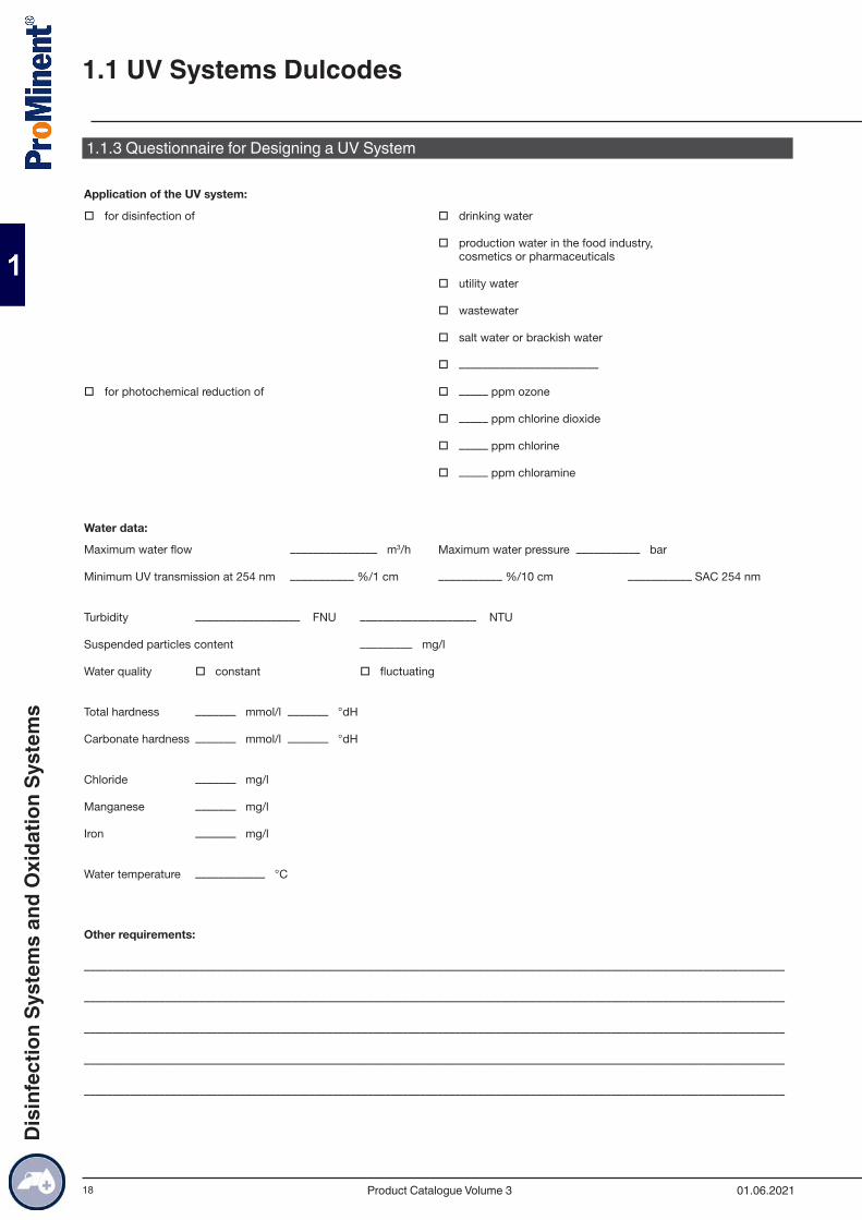
Application of the UV system:
� for disinfection of � drinking water
� production water in the food industry,cosmetics or pharmaceuticals
� utility water
� wastewater
� salt water or brackish water
� ––––––––––––––––––––––––
� for photochemical reduction of � ––––– ppm ozone
� ––––– ppm chlorine dioxide
� ––––– ppm chlorine
� ––––– ppm chloramine
Water data:
Maximum water flow ––––––––––––––– m3/h Maximum water pressure ––––––––––– bar
Minimum UV transmission at 254 nm ––––––––––– %/1 cm ––––––––––– %/10 cm ––––––––––– SAC 254 nm
Turbidity –––––––––––––––––– FNU –––––––––––––––––––– NTU
Suspended particles content ––––––––– mg/l
Water quality � constant � fluctuating
Total hardness ––––––– mmol/l ––––––– °dH
Carbonate hardness ––––––– mmol/l ––––––– °dH
Chloride ––––––– mg/l
Manganese ––––––– mg/l
Iron ––––––– mg/l
Water temperature –––––––––––– °C
Other requirements:
–––––––––––––––––––––––––––––––––––––––––––––––––––––––––––––––––––––––––––––––––––––––––––––––––––––––––––––––––––––––––
–––––––––––––––––––––––––––––––––––––––––––––––––––––––––––––––––––––––––––––––––––––––––––––––––––––––––––––––––––––––––
–––––––––––––––––––––––––––––––––––––––––––––––––––––––––––––––––––––––––––––––––––––––––––––––––––––––––––––––––––––––––
–––––––––––––––––––––––––––––––––––––––––––––––––––––––––––––––––––––––––––––––––––––––––––––––––––––––––––––––––––––––––
–––––––––––––––––––––––––––––––––––––––––––––––––––––––––––––––––––––––––––––––––––––––––––––––––––––––––––––––––––––––––
1.1 UV Systems Dulcodes
01.06.2021Product Catalogue Volume 3
Dis
infe
ctio
n Sy
stem
s an
d O
xida
tion
Syst
ems
19
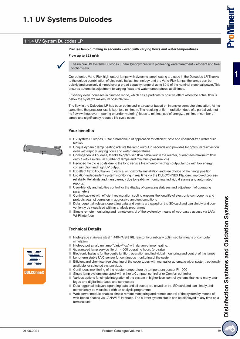
1.1.4 UV System Dulcodes LPPrecise lamp dimming in seconds – even with varying flows and water temperatures
Flow up to 523 m³/h
9 The unique UV systems Dulcodes LP are synonymous with pioneering water treatment – efficient and free of chemicals.
Our patented Vario-Flux high-output lamps with dynamic lamp heating are used in the Dulcodes LP. Thanks to the unique combination of electronic ballast technology and the Vario-Flux lamps, the lamps can be quickly and precisely dimmed over a broad capacity range of up to 50% of the nominal electrical power. This ensures automatic adjustment to varying flows and water temperatures at all times.
Efficiency even increases in dimmed mode, which has a particularly positive effect when the actual flow is below the system’s maximum possible flow.
The flow in the Dulcodes LP has been optimised in a reactor based on intensive computer simulation. At the same time the pressure loss is kept to a minimum. The resulting uniform radiation dose of a partial volumet-ric flow (without over-metering or under-metering) leads to minimal use of energy, a minimum number of lamps and significantly reduced life cycle costs.
Your benefits
■ UV system Dulcodes LP for a broad field of application for efficient, safe and chemical-free water disin-fection
■ Unique dynamic lamp heating adjusts the lamp output in seconds and provides for optimum disinfection even with rapidly varying flows and water temperatures
■ Homogeneous UV dose, thanks to optimised flow behaviour in the reactor, guarantees maximum flow output with a minimum number of lamps and minimum pressure loss
■ Reduced life cycle costs due to the long service life of Vario-Flux high-output lamps with low energy consumption and high UV output
■ Excellent flexibility, thanks to vertical or horizontal installation and free choice of the flange position ■ Location-independent system monitoring in real time via the DULCONNEX Platform: Improved process
reliability. Reliability and transparency due to real-time monitoring, individual alarms and automated reports.
■ User-friendly and intuitive control for the display of operating statuses and adjustment of operating parameters
■ Control cabinet with efficient recirculation cooling ensures the long life of electronic components and protects against corrosion in aggressive ambient conditions
■ Data logger: all relevant operating data and events are saved on the SD card and can simply and con-veniently be visualised with an analysis programme
■ Simple remote monitoring and remote control of the system by means of web-based access via LAN/Wi-Fi interface
Technical Details
■ High-grade stainless steel 1.4404/AISI316L reactor hydraulically optimised by means of computer simulation
■ High-output amalgam lamp “Vario-Flux” with dynamic lamp heating. ■ Guaranteed lamp service life of 14,000 operating hours (pro rata) ■ Electronic ballasts for the gentle ignition, operation and individual monitoring and control of the lamps ■ Long-term stable UVC sensor for continuous monitoring of the system ■ Efficient and chemical-free cleaning of the cover tubes with manual or automatic wiper system, optionally
available for selected system sizes ■ Continuous monitoring of the reactor temperature by temperature sensor Pt 1000 ■ Single lamp system: equipped with either a Compact controller or Comfort controller ■ Various options for simple integration of the system in higher-level control systems thanks to many ana-
logue and digital interfaces and connectors ■ Data logger: all relevant operating data and ell events are saved on the SD card and can simply and
conveniently be visualised with an analysis programme ■ Web server module enables simple remote monitoring and remote control of the system by means of
web-based access via LAN/Wi-Fi interface. The current system status can be displayed at any time on a terminal unit
1.1 UV Systems Dulcodes
01.06.2021 Product Catalogue Volume 3
Dis
infe
ctio
n Sy
stem
s an
d O
xida
tion
Syst
ems
20
Field of application
■ Potable water treatment ■ Food and beverage production ■ Swimming pool water
1.1 UV Systems Dulcodes
01.06.2021Product Catalogue Volume 3
Dis
infe
ctio
n Sy
stem
s an
d O
xida
tion
Syst
ems
21
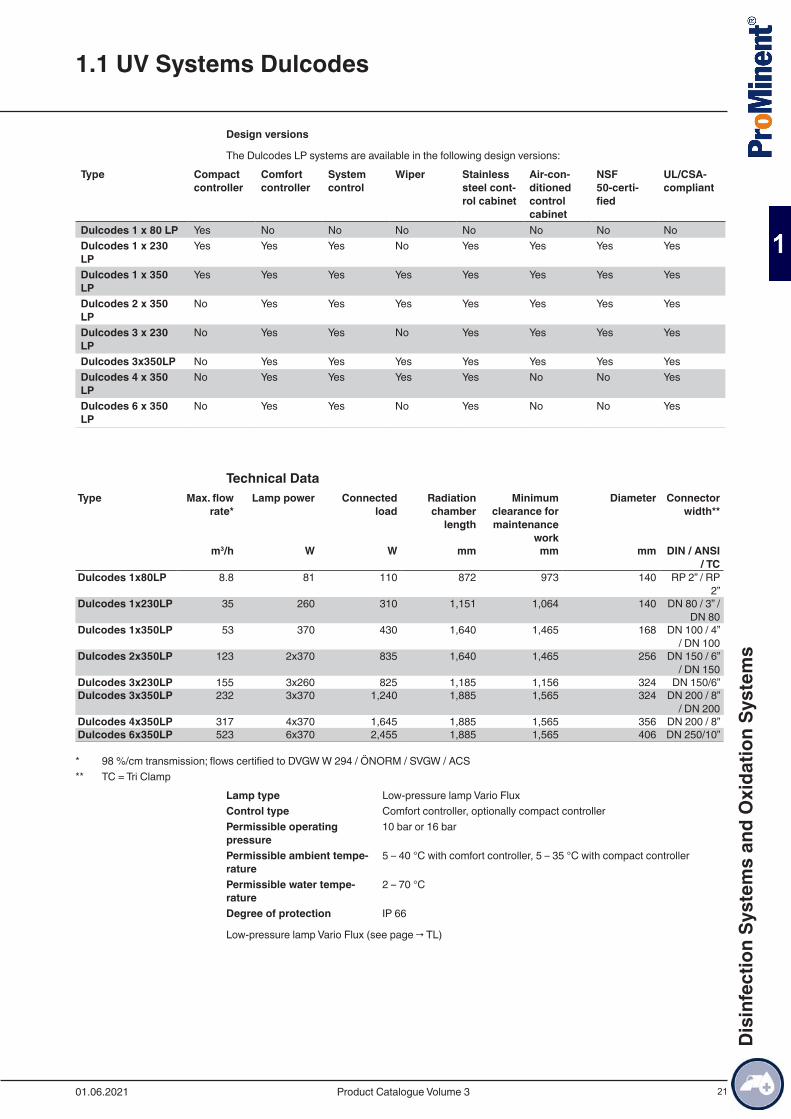
Design versions
The Dulcodes LP systems are available in the following design versions:Type Compact
controllerComfort controller
System control
Wiper Stainless steel cont-rol cabinet
Air-con-ditioned control cabinet
NSF 50-certi-fied
UL/CSA-compliant
Dulcodes 1 x 80 LP Yes No No No No No No NoDulcodes 1 x 230 LP
Yes Yes Yes No Yes Yes Yes Yes
Dulcodes 1 x 350 LP
Yes Yes Yes Yes Yes Yes Yes Yes
Dulcodes 2 x 350 LP
No Yes Yes Yes Yes Yes Yes Yes
Dulcodes 3 x 230 LP
No Yes Yes No Yes Yes Yes Yes
Dulcodes 3x350LP No Yes Yes Yes Yes Yes Yes YesDulcodes 4 x 350 LP
No Yes Yes Yes Yes No No Yes
Dulcodes 6 x 350 LP
No Yes Yes No Yes No No Yes
Technical DataType Max. flow
rate*Lamp power Connected
loadRadiation chamber
length
Minimum clearance for maintenance
work
Diameter Connector width**
m3/h W W mm mm mm DIN / ANSI / TC
Dulcodes 1x80LP 8.8 81 110 872 973 140 RP 2” / RP 2”
Dulcodes 1x230LP 35 260 310 1,151 1,064 140 DN 80 / 3” / DN 80
Dulcodes 1x350LP 53 370 430 1,640 1,465 168 DN 100 / 4” / DN 100
Dulcodes 2x350LP 123 2x370 835 1,640 1,465 256 DN 150 / 6” / DN 150
Dulcodes 3x230LP 155 3x260 825 1,185 1,156 324 DN 150/6”Dulcodes 3x350LP 232 3x370 1,240 1,885 1,565 324 DN 200 / 8”
/ DN 200Dulcodes 4x350LP 317 4x370 1,645 1,885 1,565 356 DN 200 / 8”Dulcodes 6x350LP 523 6x370 2,455 1,885 1,565 406 DN 250/10”
* 98 %/cm transmission; flows certified to DVGW W 294 / ÖNORM / SVGW / ACS** TC = Tri Clamp
Lamp type Low-pressure lamp Vario FluxControl type Comfort controller, optionally compact controllerPermissible operating pressure
10 bar or 16 bar
Permissible ambient tempe-rature
5 – 40 °C with comfort controller, 5 – 35 °C with compact controller
Permissible water tempe-rature
2 – 70 °C
Degree of protection IP 66
Low-pressure lamp Vario Flux (see page → TL)
1.1 UV Systems Dulcodes
01.06.2021 Product Catalogue Volume 3
Dis
infe
ctio
n Sy
stem
s an
d O
xida
tion
Syst
ems
22
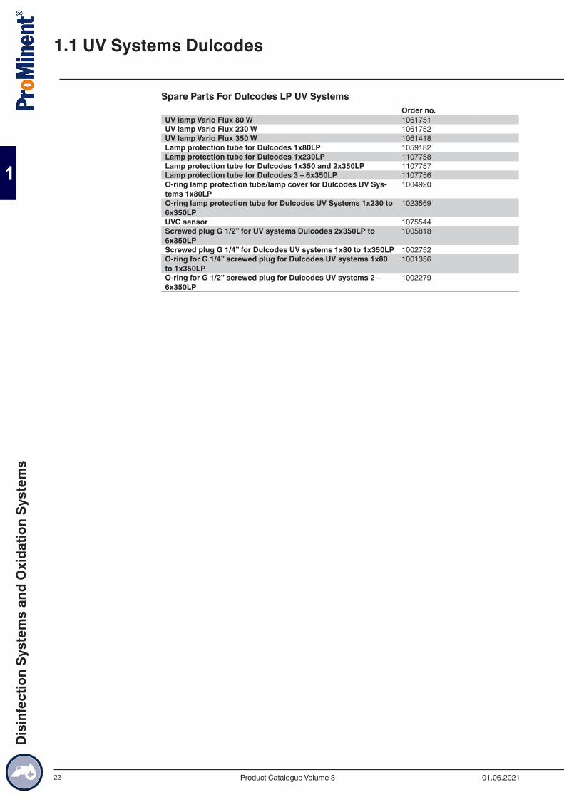
Spare Parts For Dulcodes LP UV SystemsOrder no.
UV lamp Vario Flux 80 W 1061751UV lamp Vario Flux 230 W 1061752UV lamp Vario Flux 350 W 1061418Lamp protection tube for Dulcodes 1x80LP 1059182Lamp protection tube for Dulcodes 1x230LP 1107758Lamp protection tube for Dulcodes 1x350 and 2x350LP 1107757Lamp protection tube for Dulcodes 3 – 6x350LP 1107756O-ring lamp protection tube/lamp cover for Dulcodes UV Sys-tems 1x80LP
1004920
O-ring lamp protection tube for Dulcodes UV Systems 1x230 to 6x350LP
1023569
UVC sensor 1075544Screwed plug G 1/2” for UV systems Dulcodes 2x350LP to 6x350LP
1005818
Screwed plug G 1/4” for Dulcodes UV systems 1x80 to 1x350LP 1002752O-ring for G 1/4” screwed plug for Dulcodes UV systems 1x80 to 1x350LP
1001356
O-ring for G 1/2” screwed plug for Dulcodes UV systems 2 – 6x350LP
1002279
1.1 UV Systems Dulcodes
01.06.2021Product Catalogue Volume 3
Dis
infe
ctio
n Sy
stem
s an
d O
xida
tion
Syst
ems
23
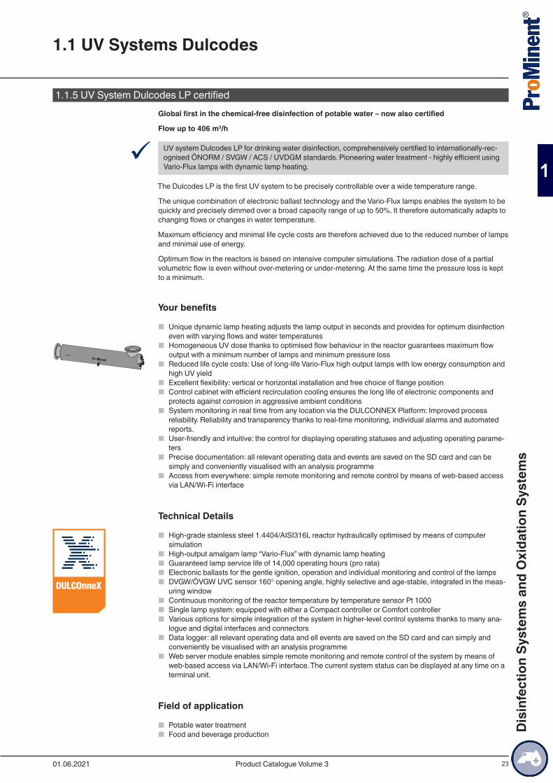
1.1.5 UV System Dulcodes LP certifiedGlobal first in the chemical-free disinfection of potable water – now also certified
Flow up to 406 m3/h
9 UV system Dulcodes LP for drinking water disinfection, comprehensively certified to internationally-rec-ognised ÖNORM / SVGW / ACS / UVDGM standards. Pioneering water treatment - highly efficient using Vario-Flux lamps with dynamic lamp heating.
The Dulcodes LP is the first UV system to be precisely controllable over a wide temperature range.
The unique combination of electronic ballast technology and the Vario-Flux lamps enables the system to be quickly and precisely dimmed over a broad capacity range of up to 50%. It therefore automatically adapts to changing flows or changes in water temperature.
Maximum efficiency and minimal life cycle costs are therefore achieved due to the reduced number of lamps and minimal use of energy.
Optimum flow in the reactors is based on intensive computer simulations. The radiation dose of a partial volumetric flow is even without over-metering or under-metering. At the same time the pressure loss is kept to a minimum.
Your benefits
■ Unique dynamic lamp heating adjusts the lamp output in seconds and provides for optimum disinfection even with varying flows and water temperatures
■ Homogeneous UV dose thanks to optimised flow behaviour in the reactor guarantees maximum flow output with a minimum number of lamps and minimum pressure loss
■ Reduced life cycle costs: Use of long-life Vario-Flux high output lamps with low energy consumption and high UV yield
■ Excellent flexibility: vertical or horizontal installation and free choice of flange position ■ Control cabinet with efficient recirculation cooling ensures the long life of electronic components and
protects against corrosion in aggressive ambient conditions ■ System monitoring in real time from any location via the DULCONNEX Platform: Improved process
reliability. Reliability and transparency thanks to real-time monitoring, individual alarms and automated reports.
■ User-friendly and intuitive: the control for displaying operating statuses and adjusting operating parame-ters
■ Precise documentation: all relevant operating data and events are saved on the SD card and can be simply and conveniently visualised with an analysis programme
■ Access from everywhere: simple remote monitoring and remote control by means of web-based access via LAN/Wi-Fi interface
Technical Details
■ High-grade stainless steel 1.4404/AISI316L reactor hydraulically optimised by means of computer simulation
■ High-output amalgam lamp “Vario-Flux” with dynamic lamp heating ■ Guaranteed lamp service life of 14,000 operating hours (pro rata) ■ Electronic ballasts for the gentle ignition, operation and individual monitoring and control of the lamps ■ DVGW/ÖVGW UVC sensor 160° opening angle, highly selective and age-stable, integrated in the meas-
uring window ■ Continuous monitoring of the reactor temperature by temperature sensor Pt 1000 ■ Single lamp system: equipped with either a Compact controller or Comfort controller ■ Various options for simple integration of the system in higher-level control systems thanks to many ana-
logue and digital interfaces and connectors ■ Data logger: all relevant operating data and ell events are saved on the SD card and can simply and
conveniently be visualised with an analysis programme ■ Web server module enables simple remote monitoring and remote control of the system by means of
web-based access via LAN/Wi-Fi interface. The current system status can be displayed at any time on a terminal unit.
Field of application
■ Potable water treatment ■ Food and beverage production
1.1 UV Systems Dulcodes
01.06.2021 Product Catalogue Volume 3
Dis
infe
ctio
n Sy
stem
s an
d O
xida
tion
Syst
ems
24
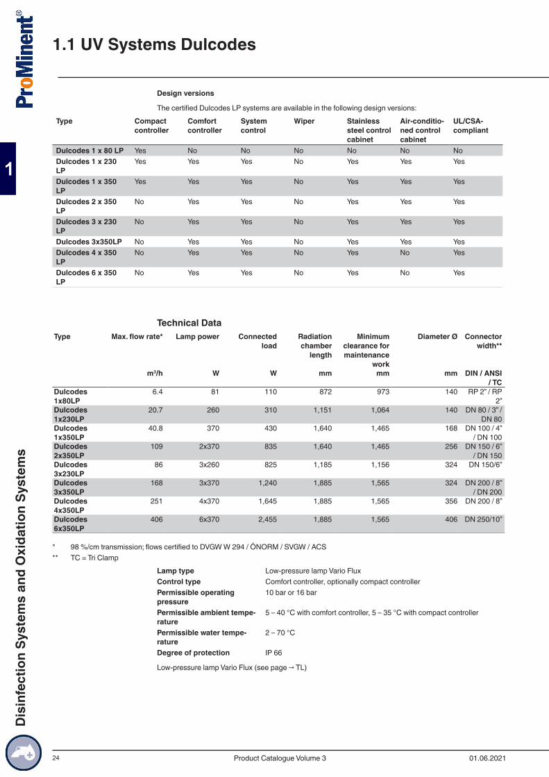
Design versions
The certified Dulcodes LP systems are available in the following design versions:Type Compact
controllerComfort controller
System control
Wiper Stainless steel control cabinet
Air-conditio-ned control cabinet
UL/CSA-compliant
Dulcodes 1 x 80 LP Yes No No No No No NoDulcodes 1 x 230 LP
Yes Yes Yes No Yes Yes Yes
Dulcodes 1 x 350 LP
Yes Yes Yes No Yes Yes Yes
Dulcodes 2 x 350 LP
No Yes Yes No Yes Yes Yes
Dulcodes 3 x 230 LP
No Yes Yes No Yes Yes Yes
Dulcodes 3x350LP No Yes Yes No Yes Yes YesDulcodes 4 x 350 LP
No Yes Yes No Yes No Yes
Dulcodes 6 x 350 LP
No Yes Yes No Yes No Yes
Technical DataType Max. flow rate* Lamp power Connected
loadRadiation chamber
length
Minimum clearance for maintenance
work
Diameter Ø Connector width**
m3/h W W mm mm mm DIN / ANSI / TC
Dulcodes 1x80LP
6.4 81 110 872 973 140 RP 2” / RP 2”
Dulcodes 1x230LP
20.7 260 310 1,151 1,064 140 DN 80 / 3” / DN 80
Dulcodes 1x350LP
40.8 370 430 1,640 1,465 168 DN 100 / 4” / DN 100
Dulcodes 2x350LP
109 2x370 835 1,640 1,465 256 DN 150 / 6” / DN 150
Dulcodes 3x230LP
86 3x260 825 1,185 1,156 324 DN 150/6”
Dulcodes 3x350LP
168 3x370 1,240 1,885 1,565 324 DN 200 / 8” / DN 200
Dulcodes 4x350LP
251 4x370 1,645 1,885 1,565 356 DN 200 / 8”
Dulcodes 6x350LP
406 6x370 2,455 1,885 1,565 406 DN 250/10”
* 98 %/cm transmission; flows certified to DVGW W 294 / ÖNORM / SVGW / ACS** TC = Tri Clamp
Lamp type Low-pressure lamp Vario FluxControl type Comfort controller, optionally compact controllerPermissible operating pressure
10 bar or 16 bar
Permissible ambient tempe-rature
5 – 40 °C with comfort controller, 5 – 35 °C with compact controller
Permissible water tempe-rature
2 – 70 °C
Degree of protection IP 66
Low-pressure lamp Vario Flux (see page → TL)
1.1 UV Systems Dulcodes
01.06.2021Product Catalogue Volume 3
Dis
infe
ctio
n Sy
stem
s an
d O
xida
tion
Syst
ems
25
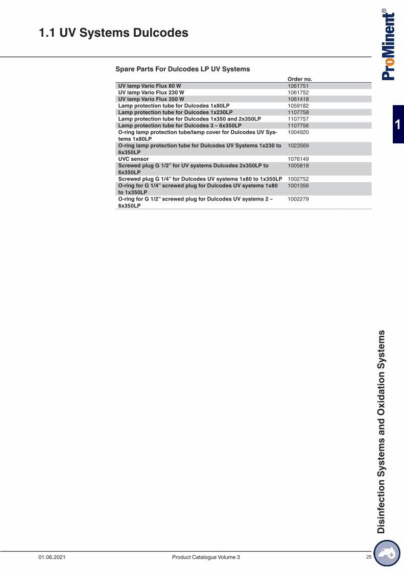
Spare Parts For Dulcodes LP UV SystemsOrder no.
UV lamp Vario Flux 80 W 1061751UV lamp Vario Flux 230 W 1061752UV lamp Vario Flux 350 W 1061418Lamp protection tube for Dulcodes 1x80LP 1059182Lamp protection tube for Dulcodes 1x230LP 1107758Lamp protection tube for Dulcodes 1x350 and 2x350LP 1107757Lamp protection tube for Dulcodes 3 – 6x350LP 1107756O-ring lamp protection tube/lamp cover for Dulcodes UV Sys-tems 1x80LP
1004920
O-ring lamp protection tube for Dulcodes UV Systems 1x230 to 6x350LP
1023569
UVC sensor 1076149Screwed plug G 1/2” for UV systems Dulcodes 2x350LP to 6x350LP
1005818
Screwed plug G 1/4” for Dulcodes UV systems 1x80 to 1x350LP 1002752O-ring for G 1/4” screwed plug for Dulcodes UV systems 1x80 to 1x350LP
1001356
O-ring for G 1/2” screwed plug for Dulcodes UV systems 2 – 6x350LP
1002279
1.1 UV Systems Dulcodes
01.06.2021 Product Catalogue Volume 3
Dis
infe
ctio
n Sy
stem
s an
d O
xida
tion
Syst
ems
26
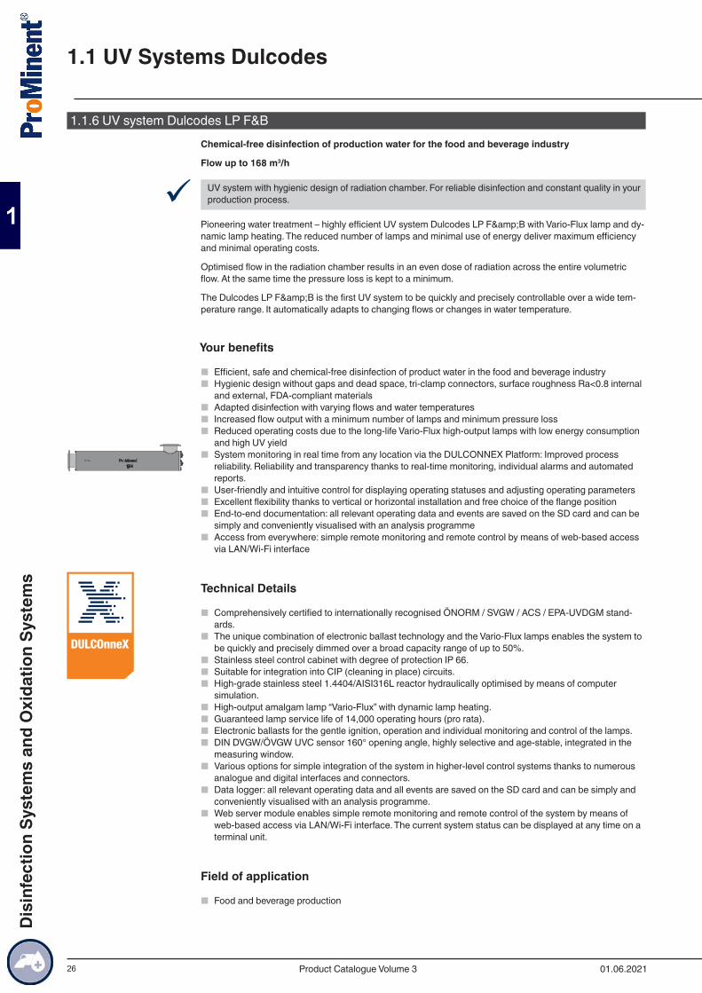
1.1.6 UV system Dulcodes LP F&BChemical-free disinfection of production water for the food and beverage industry
Flow up to 168 m3/h
9 UV system with hygienic design of radiation chamber. For reliable disinfection and constant quality in your production process.
Pioneering water treatment – highly efficient UV system Dulcodes LP F&B with Vario-Flux lamp and dy-namic lamp heating. The reduced number of lamps and minimal use of energy deliver maximum efficiency and minimal operating costs.
Optimised flow in the radiation chamber results in an even dose of radiation across the entire volumetric flow. At the same time the pressure loss is kept to a minimum.
The Dulcodes LP F&B is the first UV system to be quickly and precisely controllable over a wide tem-perature range. It automatically adapts to changing flows or changes in water temperature.
Your benefits
■ Efficient, safe and chemical-free disinfection of product water in the food and beverage industry ■ Hygienic design without gaps and dead space, tri-clamp connectors, surface roughness Ra<0.8 internal
and external, FDA-compliant materials ■ Adapted disinfection with varying flows and water temperatures ■ Increased flow output with a minimum number of lamps and minimum pressure loss ■ Reduced operating costs due to the long-life Vario-Flux high-output lamps with low energy consumption
and high UV yield ■ System monitoring in real time from any location via the DULCONNEX Platform: Improved process
reliability. Reliability and transparency thanks to real-time monitoring, individual alarms and automated reports.
■ User-friendly and intuitive control for displaying operating statuses and adjusting operating parameters ■ Excellent flexibility thanks to vertical or horizontal installation and free choice of the flange position ■ End-to-end documentation: all relevant operating data and events are saved on the SD card and can be
simply and conveniently visualised with an analysis programme ■ Access from everywhere: simple remote monitoring and remote control by means of web-based access
via LAN/Wi-Fi interface
Technical Details
■ Comprehensively certified to internationally recognised ÖNORM / SVGW / ACS / EPA-UVDGM stand-ards.
■ The unique combination of electronic ballast technology and the Vario-Flux lamps enables the system to be quickly and precisely dimmed over a broad capacity range of up to 50%.
■ Stainless steel control cabinet with degree of protection IP 66. ■ Suitable for integration into CIP (cleaning in place) circuits. ■ High-grade stainless steel 1.4404/AISI316L reactor hydraulically optimised by means of computer
simulation. ■ High-output amalgam lamp “Vario-Flux” with dynamic lamp heating. ■ Guaranteed lamp service life of 14,000 operating hours (pro rata). ■ Electronic ballasts for the gentle ignition, operation and individual monitoring and control of the lamps. ■ DIN DVGW/ÖVGW UVC sensor 160° opening angle, highly selective and age-stable, integrated in the
measuring window. ■ Various options for simple integration of the system in higher-level control systems thanks to numerous
analogue and digital interfaces and connectors. ■ Data logger: all relevant operating data and all events are saved on the SD card and can be simply and
conveniently visualised with an analysis programme. ■ Web server module enables simple remote monitoring and remote control of the system by means of
web-based access via LAN/Wi-Fi interface. The current system status can be displayed at any time on a terminal unit.
Field of application
■ Food and beverage production
160°
1.1 UV Systems Dulcodes
01.06.2021Product Catalogue Volume 3
Dis
infe
ctio
n Sy
stem
s an
d O
xida
tion
Syst
ems
27
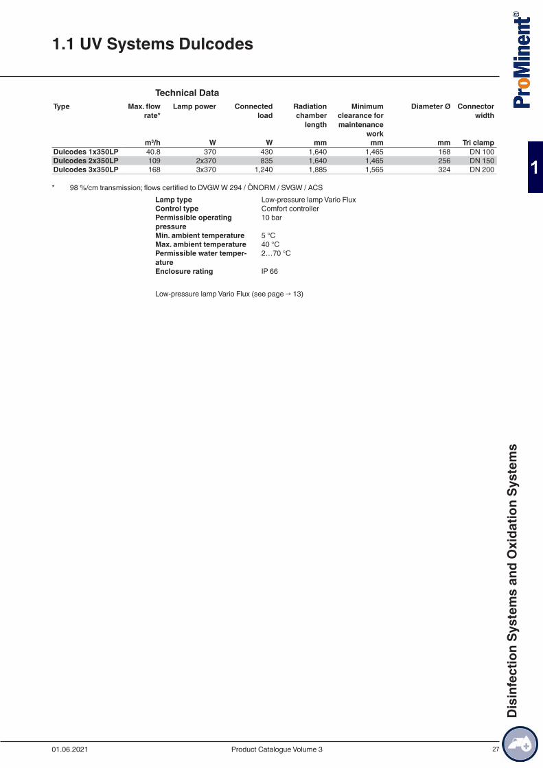
Technical DataType Max. flow
rate*Lamp power Connected
loadRadiation chamber
length
Minimum clearance for maintenance
work
Diameter Ø Connector width
m3/h W W mm mm mm Tri clampDulcodes 1x350LP 40.8 370 430 1,640 1,465 168 DN 100Dulcodes 2x350LP 109 2x370 835 1,640 1,465 256 DN 150Dulcodes 3x350LP 168 3x370 1,240 1,885 1,565 324 DN 200
* 98 %/cm transmission; flows certified to DVGW W 294 / ÖNORM / SVGW / ACSLamp type Low-pressure lamp Vario FluxControl type Comfort controllerPermissible operating pressure
10 bar
Min. ambient temperature 5 °CMax. ambient temperature 40 °CPermissible water temper-ature
2…70 °C
Enclosure rating IP 66
Low-pressure lamp Vario Flux (see page → 13)
1.1 UV Systems Dulcodes
01.06.2021 Product Catalogue Volume 3
Dis
infe
ctio
n Sy
stem
s an
d O
xida
tion
Syst
ems
28
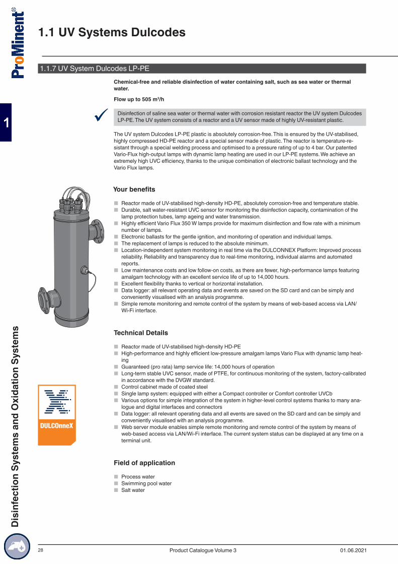
1.1.7 UV System Dulcodes LP-PEChemical-free and reliable disinfection of water containing salt, such as sea water or thermal water.
Flow up to 505 m3/h
9 Disinfection of saline sea water or thermal water with corrosion resistant reactor the UV system Dulcodes LP-PE. The UV system consists of a reactor and a UV sensor made of highly UV-resistant plastic.
The UV system Dulcodes LP-PE plastic is absolutely corrosion-free. This is ensured by the UV-stabilised, highly compressed HD-PE reactor and a special sensor made of plastic. The reactor is temperature-re-sistant through a special welding process and optimised to a pressure rating of up to 4 bar. Our patented Vario-Flux high-output lamps with dynamic lamp heating are used in our LP-PE systems. We achieve an extremely high UVC efficiency, thanks to the unique combination of electronic ballast technology and the Vario Flux lamps.
Your benefits
■ Reactor made of UV-stabilised high-density HD-PE, absolutely corrosion-free and temperature stable. ■ Durable, salt water-resistant UVC sensor for monitoring the disinfection capacity, contamination of the
lamp protection tubes, lamp ageing and water transmission. ■ Highly efficient Vario Flux 350 W lamps provide for maximum disinfection and flow rate with a minimum
number of lamps. ■ Electronic ballasts for the gentle ignition, and monitoring of operation and individual lamps. ■ The replacement of lamps is reduced to the absolute minimum. ■ Location-independent system monitoring in real time via the DULCONNEX Platform: Improved process
reliability. Reliability and transparency due to real-time monitoring, individual alarms and automated reports.
■ Low maintenance costs and low follow-on costs, as there are fewer, high-performance lamps featuring amalgam technology with an excellent service life of up to 14,000 hours.
■ Excellent flexibility thanks to vertical or horizontal installation. ■ Data logger: all relevant operating data and events are saved on the SD card and can be simply and
conveniently visualised with an analysis programme. ■ Simple remote monitoring and remote control of the system by means of web-based access via LAN/
Wi-Fi interface.
Technical Details
■ Reactor made of UV-stabilised high-density HD-PE ■ High-performance and highly efficient low-pressure amalgam lamps Vario Flux with dynamic lamp heat-
ing ■ Guaranteed (pro rata) lamp service life: 14,000 hours of operation ■ Long-term stable UVC sensor, made of PTFE, for continuous monitoring of the system, factory-calibrated
in accordance with the DVGW standard. ■ Control cabinet made of coated steel ■ Single lamp system: equipped with either a Compact controller or Comfort controller UVCb ■ Various options for simple integration of the system in higher-level control systems thanks to many ana-
logue and digital interfaces and connectors ■ Data logger: all relevant operating data and all events are saved on the SD card and can be simply and
conveniently visualised with an analysis programme. ■ Web server module enables simple remote monitoring and remote control of the system by means of
web-based access via LAN/Wi-Fi interface. The current system status can be displayed at any time on a terminal unit.
Field of application
■ Process water ■ Swimming pool water ■ Salt water
1.1 UV Systems Dulcodes
01.06.2021Product Catalogue Volume 3
Dis
infe
ctio
n Sy
stem
s an
d O
xida
tion
Syst
ems
29
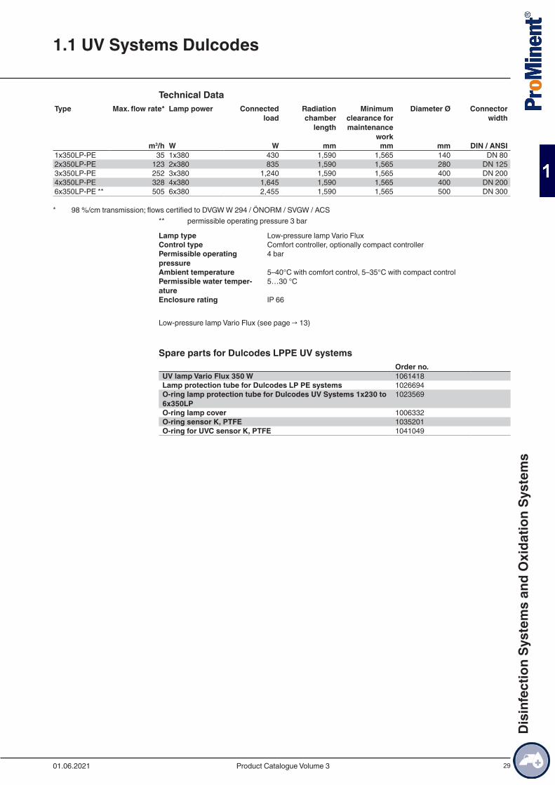
Technical DataType Max. flow rate* Lamp power Connected
loadRadiation chamber
length
Minimum clearance for maintenance
work
Diameter Ø Connector width
m3/h W W mm mm mm DIN / ANSI1x350LP-PE 35 1x380 430 1,590 1,565 140 DN 802x350LP-PE 123 2x380 835 1,590 1,565 280 DN 1253x350LP-PE 252 3x380 1,240 1,590 1,565 400 DN 2004x350LP-PE 328 4x380 1,645 1,590 1,565 400 DN 2006x350LP-PE ** 505 6x380 2,455 1,590 1,565 500 DN 300
* 98 %/cm transmission; flows certified to DVGW W 294 / ÖNORM / SVGW / ACS** permissible operating pressure 3 bar
Lamp type Low-pressure lamp Vario FluxControl type Comfort controller, optionally compact controllerPermissible operating pressure
4 bar
Ambient temperature 5–40°C with comfort control, 5–35°C with compact controlPermissible water temper-ature
5…30 °C
Enclosure rating IP 66
Low-pressure lamp Vario Flux (see page → 13)
Spare parts for Dulcodes LPPE UV systemsOrder no.
UV lamp Vario Flux 350 W 1061418Lamp protection tube for Dulcodes LP PE systems 1026694O-ring lamp protection tube for Dulcodes UV Systems 1x230 to 6x350LP
1023569
O-ring lamp cover 1006332O-ring sensor K, PTFE 1035201O-ring for UVC sensor K, PTFE 1041049
1.1 UV Systems Dulcodes
01.06.2021 Product Catalogue Volume 3
Dis
infe
ctio
n Sy
stem
s an
d O
xida
tion
Syst
ems
30
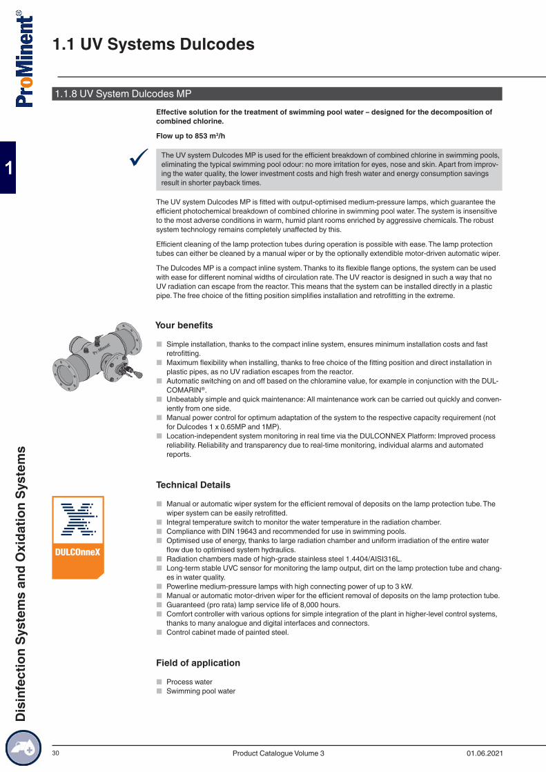
1.1.8 UV System Dulcodes MPEffective solution for the treatment of swimming pool water – designed for the decomposition of combined chlorine.
Flow up to 853 m3/h
9 The UV system Dulcodes MP is used for the efficient breakdown of combined chlorine in swimming pools, eliminating the typical swimming pool odour: no more irritation for eyes, nose and skin. Apart from improv-ing the water quality, the lower investment costs and high fresh water and energy consumption savings result in shorter payback times.
The UV system Dulcodes MP is fitted with output-optimised medium-pressure lamps, which guarantee the efficient photochemical breakdown of combined chlorine in swimming pool water. The system is insensitive to the most adverse conditions in warm, humid plant rooms enriched by aggressive chemicals. The robust system technology remains completely unaffected by this.
Efficient cleaning of the lamp protection tubes during operation is possible with ease. The lamp protection tubes can either be cleaned by a manual wiper or by the optionally extendible motor-driven automatic wiper.
The Dulcodes MP is a compact inline system. Thanks to its flexible flange options, the system can be used with ease for different nominal widths of circulation rate. The UV reactor is designed in such a way that no UV radiation can escape from the reactor. This means that the system can be installed directly in a plastic pipe. The free choice of the fitting position simplifies installation and retrofitting in the extreme.
Your benefits
■ Simple installation, thanks to the compact inline system, ensures minimum installation costs and fast retrofitting.
■ Maximum flexibility when installing, thanks to free choice of the fitting position and direct installation in plastic pipes, as no UV radiation escapes from the reactor.
■ Automatic switching on and off based on the chloramine value, for example in conjunction with the DUL-COMARIN®.
■ Unbeatably simple and quick maintenance: All maintenance work can be carried out quickly and conven-iently from one side.
■ Manual power control for optimum adaptation of the system to the respective capacity requirement (not for Dulcodes 1 x 0.65MP and 1MP).
■ Location-independent system monitoring in real time via the DULCONNEX Platform: Improved process reliability. Reliability and transparency due to real-time monitoring, individual alarms and automated reports.
Technical Details
■ Manual or automatic wiper system for the efficient removal of deposits on the lamp protection tube. The wiper system can be easily retrofitted.
■ Integral temperature switch to monitor the water temperature in the radiation chamber. ■ Compliance with DIN 19643 and recommended for use in swimming pools. ■ Optimised use of energy, thanks to large radiation chamber and uniform irradiation of the entire water
flow due to optimised system hydraulics. ■ Radiation chambers made of high-grade stainless steel 1.4404/AISI316L. ■ Long-term stable UVC sensor for monitoring the lamp output, dirt on the lamp protection tube and chang-
es in water quality. ■ Powerline medium-pressure lamps with high connecting power of up to 3 kW. ■ Manual or automatic motor-driven wiper for the efficient removal of deposits on the lamp protection tube. ■ Guaranteed (pro rata) lamp service life of 8,000 hours. ■ Comfort controller with various options for simple integration of the plant in higher-level control systems,
thanks to many analogue and digital interfaces and connectors. ■ Control cabinet made of painted steel.
Field of application
■ Process water ■ Swimming pool water
1.1 UV Systems Dulcodes
01.06.2021Product Catalogue Volume 3
Dis
infe
ctio
n Sy
stem
s an
d O
xida
tion
Syst
ems
31
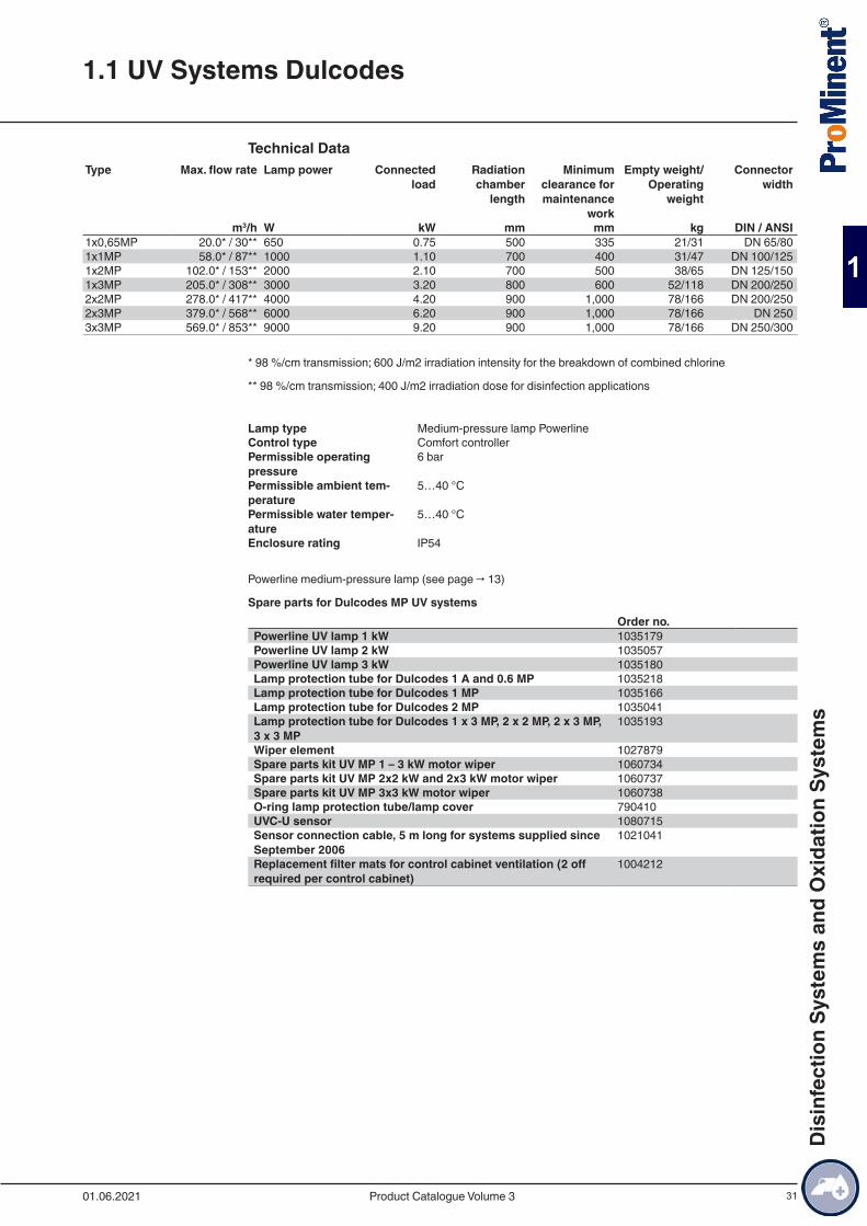
Technical DataType Max. flow rate Lamp power Connected
loadRadiation chamber
length
Minimum clearance for maintenance
work
Empty weight/Operating
weight
Connector width
m3/h W kW mm mm kg DIN / ANSI1x0,65MP 20.0* / 30** 650 0.75 500 335 21/31 DN 65/801x1MP 58.0* / 87** 1000 1.10 700 400 31/47 DN 100/1251x2MP 102.0* / 153** 2000 2.10 700 500 38/65 DN 125/1501x3MP 205.0* / 308** 3000 3.20 800 600 52/118 DN 200/2502x2MP 278.0* / 417** 4000 4.20 900 1,000 78/166 DN 200/2502x3MP 379.0* / 568** 6000 6.20 900 1,000 78/166 DN 2503x3MP 569.0* / 853** 9000 9.20 900 1,000 78/166 DN 250/300
* 98 %/cm transmission; 600 J/m2 irradiation intensity for the breakdown of combined chlorine
** 98 %/cm transmission; 400 J/m2 irradiation dose for disinfection applications
Lamp type Medium-pressure lamp PowerlineControl type Comfort controllerPermissible operating pressure
6 bar
Permissible ambient tem-perature
5…40 °C
Permissible water temper-ature
5…40 °C
Enclosure rating IP54
Powerline medium-pressure lamp (see page → 13)
Spare parts for Dulcodes MP UV systemsOrder no.
Powerline UV lamp 1 kW 1035179Powerline UV lamp 2 kW 1035057Powerline UV lamp 3 kW 1035180Lamp protection tube for Dulcodes 1 A and 0.6 MP 1035218Lamp protection tube for Dulcodes 1 MP 1035166Lamp protection tube for Dulcodes 2 MP 1035041Lamp protection tube for Dulcodes 1 x 3 MP, 2 x 2 MP, 2 x 3 MP, 3 x 3 MP
1035193
Wiper element 1027879Spare parts kit UV MP 1 – 3 kW motor wiper 1060734Spare parts kit UV MP 2x2 kW and 2x3 kW motor wiper 1060737Spare parts kit UV MP 3x3 kW motor wiper 1060738O-ring lamp protection tube/lamp cover 790410UVC-U sensor 1080715Sensor connection cable, 5 m long for systems supplied since September 2006
1021041
Replacement filter mats for control cabinet ventilation (2 off required per control cabinet)
1004212
1.1 UV Systems Dulcodes
01.06.2021 Product Catalogue Volume 3
Dis
infe
ctio
n Sy
stem
s an
d O
xida
tion
Syst
ems
32
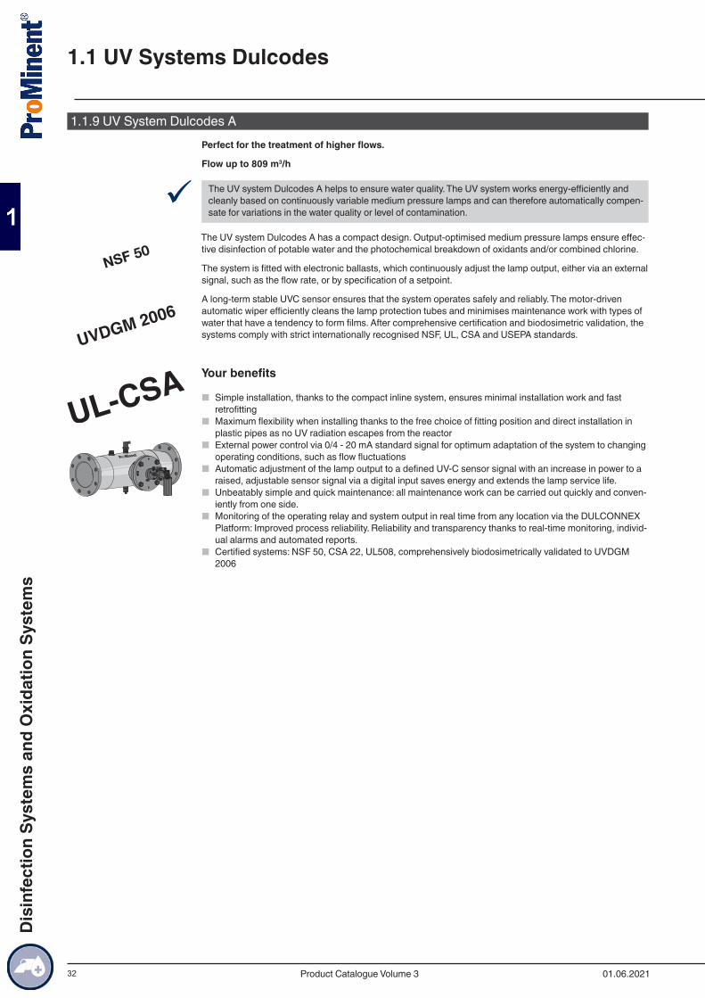
1.1.9 UV System Dulcodes APerfect for the treatment of higher flows.
Flow up to 809 m3/h
9 The UV system Dulcodes A helps to ensure water quality. The UV system works energy-efficiently and cleanly based on continuously variable medium pressure lamps and can therefore automatically compen-sate for variations in the water quality or level of contamination.
The UV system Dulcodes A has a compact design. Output-optimised medium pressure lamps ensure effec-tive disinfection of potable water and the photochemical breakdown of oxidants and/or combined chlorine.
The system is fitted with electronic ballasts, which continuously adjust the lamp output, either via an external signal, such as the flow rate, or by specification of a setpoint.
A long-term stable UVC sensor ensures that the system operates safely and reliably. The motor-driven automatic wiper efficiently cleans the lamp protection tubes and minimises maintenance work with types of water that have a tendency to form films. After comprehensive certification and biodosimetric validation, the systems comply with strict internationally recognised NSF, UL, CSA and USEPA standards.
Your benefits
■ Simple installation, thanks to the compact inline system, ensures minimal installation work and fast retrofitting
■ Maximum flexibility when installing thanks to the free choice of fitting position and direct installation in plastic pipes as no UV radiation escapes from the reactor
■ External power control via 0/4 - 20 mA standard signal for optimum adaptation of the system to changing operating conditions, such as flow fluctuations
■ Automatic adjustment of the lamp output to a defined UV-C sensor signal with an increase in power to a raised, adjustable sensor signal via a digital input saves energy and extends the lamp service life.
■ Unbeatably simple and quick maintenance: all maintenance work can be carried out quickly and conven-iently from one side.
■ Monitoring of the operating relay and system output in real time from any location via the DULCONNEX Platform: Improved process reliability. Reliability and transparency thanks to real-time monitoring, individ-ual alarms and automated reports.
■ Certified systems: NSF 50, CSA 22, UL508, comprehensively biodosimetrically validated to UVDGM 2006
1.1 UV Systems Dulcodes
01.06.2021Product Catalogue Volume 3
Dis
infe
ctio
n Sy
stem
s an
d O
xida
tion
Syst
ems
33
Technical Details
■ Optimised use of energy, thanks to large radiation chamber and uniform irradiation of the entire water flow due to optimised system hydraulics.
■ Radiation chambers made of high-grade stainless steel 1.4404/AISI316L ■ Powerline A medium-pressure lamps with high power input of up to 3 kW ■ Guaranteed (pro rata) lamp service life of 8,000 hours ■ Long-term stable UVC sensor for monitoring the lamp output, lamp protection tube fouling and changes
in water quality ■ Integral temperature sensor for monitoring the water temperature in the radiation chamber ■ Automatic motor-driven wiper for efficient removal of deposits on the lamp protection tube ■ Double, independent and automatic monitoring of the wiper function by revolution counter and limit
switch ■ Control cabinet made of coated steel ■ Freely programmable control (Comfort controller Dulcodes A) with backlit display during normal opera-
tion (green), warning (yellow) and fault (red) ■ Large graphic display to show all important operating parameters, such as the UV sensor signal, lamp
power consumption, control type and operating status ■ Interfaces and connectors for: ■ Stopcock and flushing valve ■ Control of the feed pump ■ Operating signal relay ■ Warning and alarm relay for UV intensity ■ Collective malfunction alert relay ■ Pause contact ■ Relay for monitoring reactor temperature ■ Temperature monitoring and fault indicating relay for control cabinet temperature ■ Input for external fault ■ Digital input for switch-over to second power stage ■ 4-20 mA standard signal input for flow-dependent lamp control or control dependent on measured value ■ Standard signal output 4-20 mA of UV sensor signal
Field of application
■ Potable water ■ Process water ■ Swimming pool water
1.1 UV Systems Dulcodes
01.06.2021 Product Catalogue Volume 3
Dis
infe
ctio
n Sy
stem
s an
d O
xida
tion
Syst
ems
34
Technical DataType Max. flow
rateLamp power Connected
loadRadiation chamber
length
Minimum clearance for maintenance
work
Min. dis-tance from
wall
Empty weight/Oper-ating weight
Connector width
m3/h W kW mm mm mm kg DIN / ANSI1 x 1A 50* / 83** 1.000 1.10 700 400 300 31/47 DN 100/4”1 x 2A 91* / 149** 2.000 2.10 700 500 300 38/65 DN 150/6”1 x 3A 176* / 290** 3.000 3.20 800 600 300 52/118 DN 200/8”2 x 2A 240* / 395** 4.000 4.20 900 1,000 300 78/166 DN 200/8”2 x 3A 328* / 539** 6.000 6.20 900 1,000 300 78/166 DN 250/10”3 x 3A 492* / 809** 9.000 9.20 900 1,000 300 78/166 DN 300/12”
* 98 %/cm transmission; 600 J/m2 irradiation intensity for the breakdown of combined chlorine
** 98 %/cm transmission; 400 J/m2 irradiation dose for disinfection applications
Lamp type Medium-pressure lamp Powerline APermissible operating pressure
10 bar for single-lamp systems 1 x 1A - 1 x 3A
7 bar for multiple-lamp systems 2 x 2A - 3 x 3APermissible ambient tem-perature
5…40 °C
Permissible water temper-ature
5…40 °C
Enclosure rating IP54
Powerline medium-pressure lamp (see page → 13)
Accessories for Dulcodes 1 x 1 A, 1 x 2 A and 1 x 3 AOrder no.
Cable set 25 m including lamp cable, UV sensor, Pt1000, limit switch and safety switch
1106743
Spare Parts for Dulcodes A UV SystemsOrder no.
Powerline UV lamp 1 kW 1035179Powerline UV lamp 2 kW 1041450Powerline UV lamp 3 kW 1041451Lamp protection tube for Dulcodes 1 A and 0.6 MP 1035218Lamp protection tube for Dulcodes 2 A 1041723Lamp protection tube for Dulcodes 3 A 1041485Wiper element 1027879Spare parts set for UV A 1-3 kW motor wiper 1042860Spare parts kit UV MP 2x2 kW and 2x3 kW motor wiper 1044862Spare parts kit UV MP 3x3 kW motor wiper 1044863O-ring lamp protection tube for Dulcodes UV Systems 1x230 to 6x350LP
1023569
UVC-U sensor M -1, 4-20 mA 1080714Replacement filter mats for control cabinet ventilation (2 off required per control cabinet)
1004212
1.1 UV Systems Dulcodes
01.06.2021Product Catalogue Volume 3
Dis
infe
ctio
n Sy
stem
s an
d O
xida
tion
Syst
ems
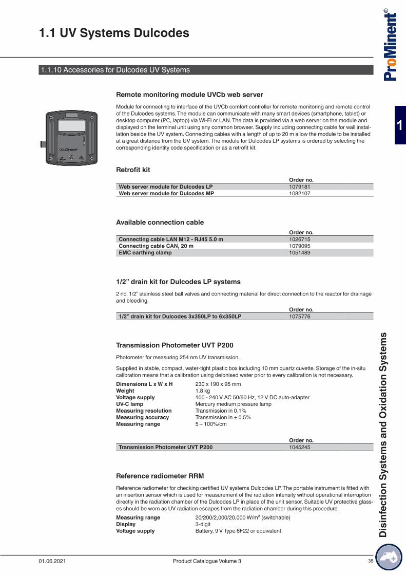
35
1.1.10 Accessories for Dulcodes UV Systems
Remote monitoring module UVCb web serverModule for connecting to interface of the UVCb comfort controller for remote monitoring and remote control of the Dulcodes systems. The module can communicate with many smart devices (smartphone, tablet) or desktop computer (PC, laptop) via Wi-Fi or LAN. The data is provided via a web server on the module and displayed on the terminal unit using any common browser. Supply including connecting cable for wall instal-lation beside the UV system. Connecting cables with a length of up to 20 m allow the module to be installed at a great distance from the UV system. The module for Dulcodes LP systems is ordered by selecting the corresponding identity code specification or as a retrofit kit.
Retrofit kitOrder no.
Web server module for Dulcodes LP 1079181Web server module for Dulcodes MP 1082107
Available connection cableOrder no.
Connecting cable LAN M12 - RJ45 5.0 m 1026715Connecting cable CAN, 20 m 1079095EMC earthing clamp 1051489
1/2” drain kit for Dulcodes LP systems2 no. 1/2” stainless steel ball valves and connecting material for direct connection to the reactor for drainage and bleeding.
Order no.1/2” drain kit for Dulcodes 3x350LP to 6x350LP 1075776
Transmission Photometer UVT P200Photometer for measuring 254 nm UV transmission.
Supplied in stable, compact, water-tight plastic box including 10 mm quartz cuvette. Storage of the in-situ calibration means that a calibration using deionised water prior to every calibration is not necessary.Dimensions L x W x H 230 x 190 x 95 mmWeight 1.8 kgVoltage supply 100 - 240 V AC 50/60 Hz, 12 V DC auto-adapterUV-C lamp Mercury medium pressure lampMeasuring resolution Transmission in 0.1%Measuring accuracy Transmission in ± 0.5%Measuring range 5 – 100%/cm
Order no.Transmission Photometer UVT P200 1045245
Reference radiometer RRMReference radiometer for checking certified UV systems Dulcodes LP. The portable instrument is fitted with an insertion sensor which is used for measurement of the radiation intensity without operational interruption directly in the radiation chamber of the Dulcodes LP in place of the unit sensor. Suitable UV protective glass-es should be worn as UV radiation escapes from the radiation chamber during this procedure.Measuring range 20/200/2,000/20,000 W/m² (switchable)Display 3-digitVoltage supply Battery, 9 V Type 6F22 or equivalent
1.1 UV Systems Dulcodes
01.06.2021 Product Catalogue Volume 3
Dis
infe
ctio
n Sy
stem
s an
d O
xida
tion
Syst
ems
36
Versionfor measuring field angle 40° for measuring field
angle 40°1025094
for measuring field angle 160° for measuring field angle 160°
1076575
for measuring field angle 40° and 160° for measuring field angle 40° and 160°
1076576
UV protective glassesProtective glasses to protect against UV radiation that may be harmful to the eye when working on open UV systems.
Order no.UV protective glasses 1025243
Protective glovesProtective gloves made of white cotton to avoid fingerprints on UV lamps and lamp protection tubes. 1 pair in universal size.
Order no.Protective gloves 1032815
Sampling valveOrder no.
Sampling valve 1074593
Cleaning systemCleaning system for flushing the radiation chamber with a cleaning concentrate to remove deposits on the lamp protection tubes and internal surfaces of the UV system. Consists of chemical tanks, feed and metering pumps, valves and complete automatic or manual controller. Design and technical equipment are matched to the particular UV system and its application.
Order no.Cleaning system on request
FittingsFittings provided for quick and easy wall mounting of the UV radiation chamber. Fitting parts comprise 2 screw-in pipe clips in high alloy steel (V2A), 2 base plates with M12 nut, 2 set screws and 4 M12 hexagon nuts.
Two-part clip with increased material cross-section to ensure high bearing strength and breaking resistance. A soundproofing layer ensures marked resistance in the sound level.
Type Order no.Fittings A2 1x80LP, 1x230LP 1039828Fittings A2 1x350LP, 3x230LP 1077823Fittings A2 2x350LP 1077844
Overvoltage ProtectionOvervoltage protection for Dulcodes UV systems, which are run at 230 V 50 - 60 Hz.
The external overvoltage protection is intended for cases where the protection provided inside the unit is not sufficient for voltage surges of 1 kV between the conductors and 2 kV to earth. To protect systems on grids with high levels of interference energy, overvoltage protection can significantly improve the interference resistance of Dulcodes systems as a precision protection measure.
1.1 UV Systems Dulcodes
01.06.2021Product Catalogue Volume 3
Dis
infe
ctio
n Sy
stem
s an
d O
xida
tion
Syst
ems

37
Only an in-depth investigation into the voltage circumstances on site can establish whether further meas-ures, such as medium-level or broad-based protection, are needed in addition to precision protection.
Order no.Fine protection PT 2-DE IS 230 IAC 733010
Replacement Plug-in Insert After TrippingOrder no.
Replacement plug-in insert PT 2-DE / S 230 / AC - ST 733011
Clip-on thermostat for systems with compact controlOrder no.
Clip-on thermostat 30-90 °C 230 VAC 1043944
1.1 UV Systems Dulcodes
01.06.2021 Product Catalogue Volume 3
Dis
infe
ctio
n Sy
stem
s an
d O
xida
tion
Syst
ems
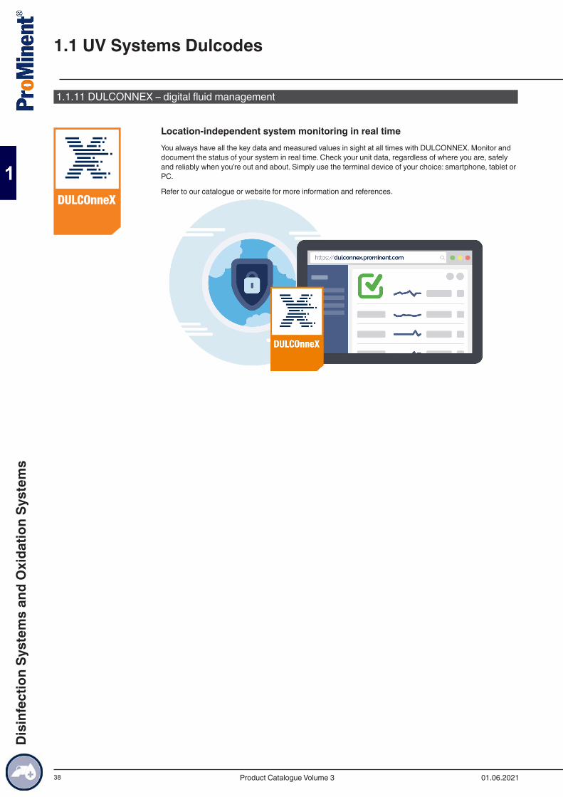
38
1.1.11 DULCONNEX – digital fluid management
Location-independent system monitoring in real timeYou always have all the key data and measured values in sight at all times with DULCONNEX. Monitor and document the status of your system in real time. Check your unit data, regardless of where you are, safely and reliably when you’re out and about. Simply use the terminal device of your choice: smartphone, tablet or PC.
Refer to our catalogue or website for more information and references.
1.1 UV Systems Dulcodes
01.06.2021Product Catalogue Volume 3
Dis
infe
ctio
n Sy
stem
s an
d O
xida
tion
Syst
ems
39
1.2.1 Ozone in Water TreatmentAs the most powerful oxidant that can be used in water treatment, ozone permits a broad spectrum of possi-ble applications:
Outstanding disinfection effectiveness against
■ Bacteria and viruses ■ Fungi and parasites
Oxidation of undesirable inorganic substances in the water
■ Iron and manganese ■ Arsenic ■ Nitrite and sulphide
Oxidation of undesirable organic substances in the water
■ Strong-smelling and strong-tasting compounds ■ Humic substances and other compounds which affect the colour of the water ■ Cyclic hydrocarbons ■ Trihalomethanes, chloramines and other chlorine compounds
Micro-flocculating action
■ After oxidation with ozone, substances and colloids dissolved in the water become insoluble and can be filtered
Significantly fewer environmentally harmful by-products result from the generation and use of ozone than with other comparable oxidants and disinfectants. As a highly reactive gas, ozone is generated on site from oxygen and introduced to the water directly without interim storage. Because of its high reactivity, ozone decomposes into oxygen again in the water, with a half-life of several minutes. Therefore all the components of an ozone treatment system have to be perfectly coordinated to one another and the planned application to achieve an optimum relationship between ozone generation and its effect.
With every new project, our engineers draw on experience that we have accumulated since 1971 in the following applications:
Potable water supply
■ Oxidation of iron, manganese or arsenic ■ Refinement and improvement of taste ■ Disinfection
Food and beverage industry
■ Disinfection of table water ■ Disinfection of rinsers in the beverage industry ■ Disinfection of production water
Swimming pools
■ Reduction of chloramines and trihalomethanes, avoiding typical swimming pool odours ■ Crystal clear water thanks to micro-flocculating action ■ Reliable microbiological barriers in therapy pools ■ Reduction in investment and operating costs through scope for reducing the circulating power and throt-
tling the fresh water inlet
Industry
■ Cooling water treatment ■ Combating legionella in cooling water circuits ■ Disinfection of process water ■ Removal of odorous substances in air scrubbers
Municipal waste water treatment
■ Removal of micropolutants ■ Reduction of clarifier sludge ■ COD reduction/breakdown ■ Removal of colour
1.2 Ozone systems OZONFILT® and DULCOZON®
01.06.2021 Product Catalogue Volume 3
Dis
infe
ctio
n Sy
stem
s an
d O
xida
tion
Syst
ems
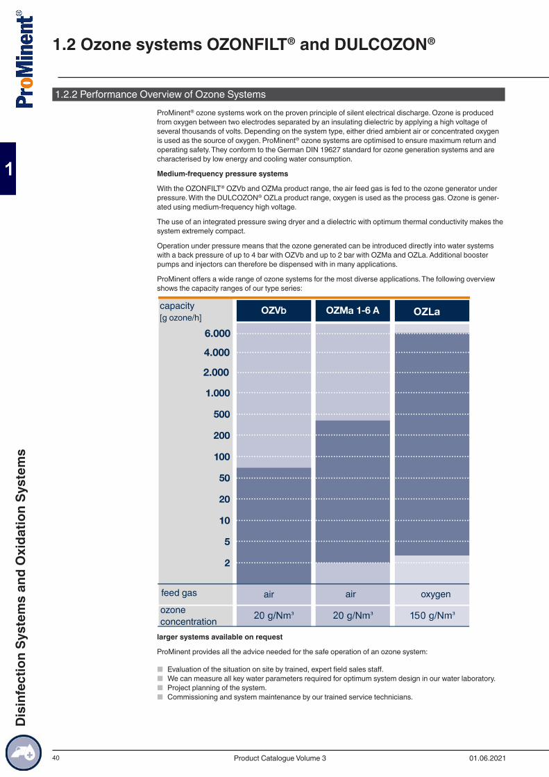
40
1.2.2 Performance Overview of Ozone SystemsProMinent® ozone systems work on the proven principle of silent electrical discharge. Ozone is produced from oxygen between two electrodes separated by an insulating dielectric by applying a high voltage of several thousands of volts. Depending on the system type, either dried ambient air or concentrated oxygen is used as the source of oxygen. ProMinent® ozone systems are optimised to ensure maximum return and operating safety. They conform to the German DIN 19627 standard for ozone generation systems and are characterised by low energy and cooling water consumption.
Medium-frequency pressure systems
With the OZONFILT® OZVb and OZMa product range, the air feed gas is fed to the ozone generator under pressure. With the DULCOZON® OZLa product range, oxygen is used as the process gas. Ozone is gener-ated using medium-frequency high voltage.
The use of an integrated pressure swing dryer and a dielectric with optimum thermal conductivity makes the system extremely compact.
Operation under pressure means that the ozone generated can be introduced directly into water systems with a back pressure of up to 4 bar with OZVb and up to 2 bar with OZMa and OZLa. Additional booster pumps and injectors can therefore be dispensed with in many applications.
ProMinent offers a wide range of ozone systems for the most diverse applications. The following overview shows the capacity ranges of our type series:
2.000
4.000
6.000
capacity[g ozone/h]
air air oxygenfeed gas
ozoneconcentration
larger systems available on request
ProMinent provides all the advice needed for the safe operation of an ozone system:
■ Evaluation of the situation on site by trained, expert field sales staff. ■ We can measure all key water parameters required for optimum system design in our water laboratory. ■ Project planning of the system. ■ Commissioning and system maintenance by our trained service technicians.
1.2 Ozone systems OZONFILT® and DULCOZON®
01.06.2021Product Catalogue Volume 3
Dis
infe
ctio
n Sy
stem
s an
d O
xida
tion
Syst
ems
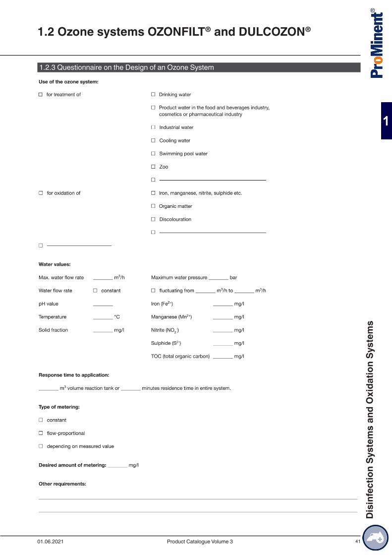
41
1.2.3 Questionnaire on the Design of an Ozone System
1.2 Ozone systems OZONFILT® and DULCOZON®
01.06.2021 Product Catalogue Volume 3
Dis
infe
ctio
n Sy
stem
s an
d O
xida
tion
Syst
ems
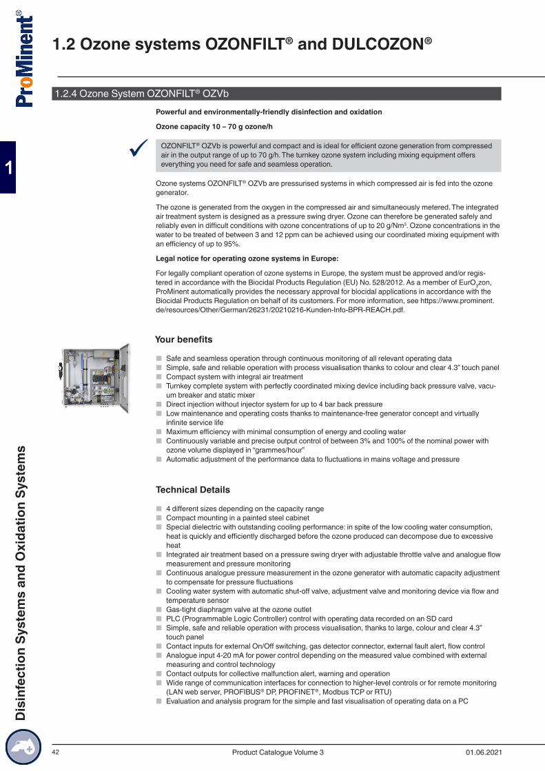
42
1.2.4 Ozone System OZONFILT® OZVbPowerful and environmentally-friendly disinfection and oxidation
Ozone capacity 10 – 70 g ozone/h
9 OZONFILT® OZVb is powerful and compact and is ideal for efficient ozone generation from compressed air in the output range of up to 70 g/h. The turnkey ozone system including mixing equipment offers everything you need for safe and seamless operation.
Ozone systems OZONFILT® OZVb are pressurised systems in which compressed air is fed into the ozone generator.
The ozone is generated from the oxygen in the compressed air and simultaneously metered. The integrated air treatment system is designed as a pressure swing dryer. Ozone can therefore be generated safely and reliably even in difficult conditions with ozone concentrations of up to 20 g/Nm3. Ozone concentrations in the water to be treated of between 3 and 12 ppm can be achieved using our coordinated mixing equipment with an efficiency of up to 95%.
Legal notice for operating ozone systems in Europe:
For legally compliant operation of ozone systems in Europe, the system must be approved and/or regis-tered in accordance with the Biocidal Products Regulation (EU) No. 528/2012. As a member of EurO3zon, ProMinent automatically provides the necessary approval for biocidal applications in accordance with the Biocidal Products Regulation on behalf of its customers. For more information, see https://www.prominent.de/resources/Other/German/26231/20210216-Kunden-Info-BPR-REACH.pdf.
Your benefits
■ Safe and seamless operation through continuous monitoring of all relevant operating data ■ Simple, safe and reliable operation with process visualisation thanks to colour and clear 4.3” touch panel ■ Compact system with integral air treatment ■ Turnkey complete system with perfectly coordinated mixing device including back pressure valve, vacu-
um breaker and static mixer ■ Direct injection without injector system for up to 4 bar back pressure ■ Low maintenance and operating costs thanks to maintenance-free generator concept and virtually
infinite service life ■ Maximum efficiency with minimal consumption of energy and cooling water ■ Continuously variable and precise output control of between 3% and 100% of the nominal power with
ozone volume displayed in “grammes/hour” ■ Automatic adjustment of the performance data to fluctuations in mains voltage and pressure
Technical Details
■ 4 different sizes depending on the capacity range ■ Compact mounting in a painted steel cabinet ■ Special dielectric with outstanding cooling performance: in spite of the low cooling water consumption,
heat is quickly and efficiently discharged before the ozone produced can decompose due to excessive heat
■ Integrated air treatment based on a pressure swing dryer with adjustable throttle valve and analogue flow measurement and pressure monitoring
■ Continuous analogue pressure measurement in the ozone generator with automatic capacity adjustment to compensate for pressure fluctuations
■ Cooling water system with automatic shut-off valve, adjustment valve and monitoring device via flow and temperature sensor
■ Gas-tight diaphragm valve at the ozone outlet ■ PLC (Programmable Logic Controller) control with operating data recorded on an SD card ■ Simple, safe and reliable operation with process visualisation, thanks to large, colour and clear 4.3”
touch panel ■ Contact inputs for external On/Off switching, gas detector connector, external fault alert, flow control ■ Analogue input 4-20 mA for power control depending on the measured value combined with external
measuring and control technology ■ Contact outputs for collective malfunction alert, warning and operation ■ Wide range of communication interfaces for connection to higher-level controls or for remote monitoring
(LAN web server, PROFIBUS® DP, PROFINET®, Modbus TCP or RTU) ■ Evaluation and analysis program for the simple and fast visualisation of operating data on a PC
1.2 Ozone systems OZONFILT® and DULCOZON®
01.06.2021Product Catalogue Volume 3
Dis
infe
ctio
n Sy
stem
s an
d O
xida
tion
Syst
ems
43
Options
■ Stainless steel control cabinet ■ Pressure controller with filter unit at the compressed air input ■ Different designs of ready-wired installed mixing unit up to complete equipment including back pressure
valve, vacuum breaker and integral static mixer ■ Air conditioning: The system can be equipped with integral air conditioning with ambient temperatures
above 40 °C ■ Control of a cooling water heat exchanger ■ Integration of a dew point sensor to monitor the quality of compressed air
Field of application
■ Potable water supply: Oxidation of iron, manganese and arsenic, refinement and taste enhancement and disinfection
■ Waste water treatment: Degradation/reduction of COD and microcontaminants, reduction of sewage sludge
■ Food and beverage industry: Oxidation of iron and manganese, disinfection of potable water and rinser water
■ Swimming pools: Degradation of disinfection by-products, reliable microbiological barrier and produc-tion of crystal-clear water thanks to its microflocculating effect
■ Industry: Legionella prevention and disinfection of cooling water
1.2 Ozone systems OZONFILT® and DULCOZON®
01.06.2021 Product Catalogue Volume 3
Dis
infe
ctio
n Sy
stem
s an
d O
xida
tion
Syst
ems
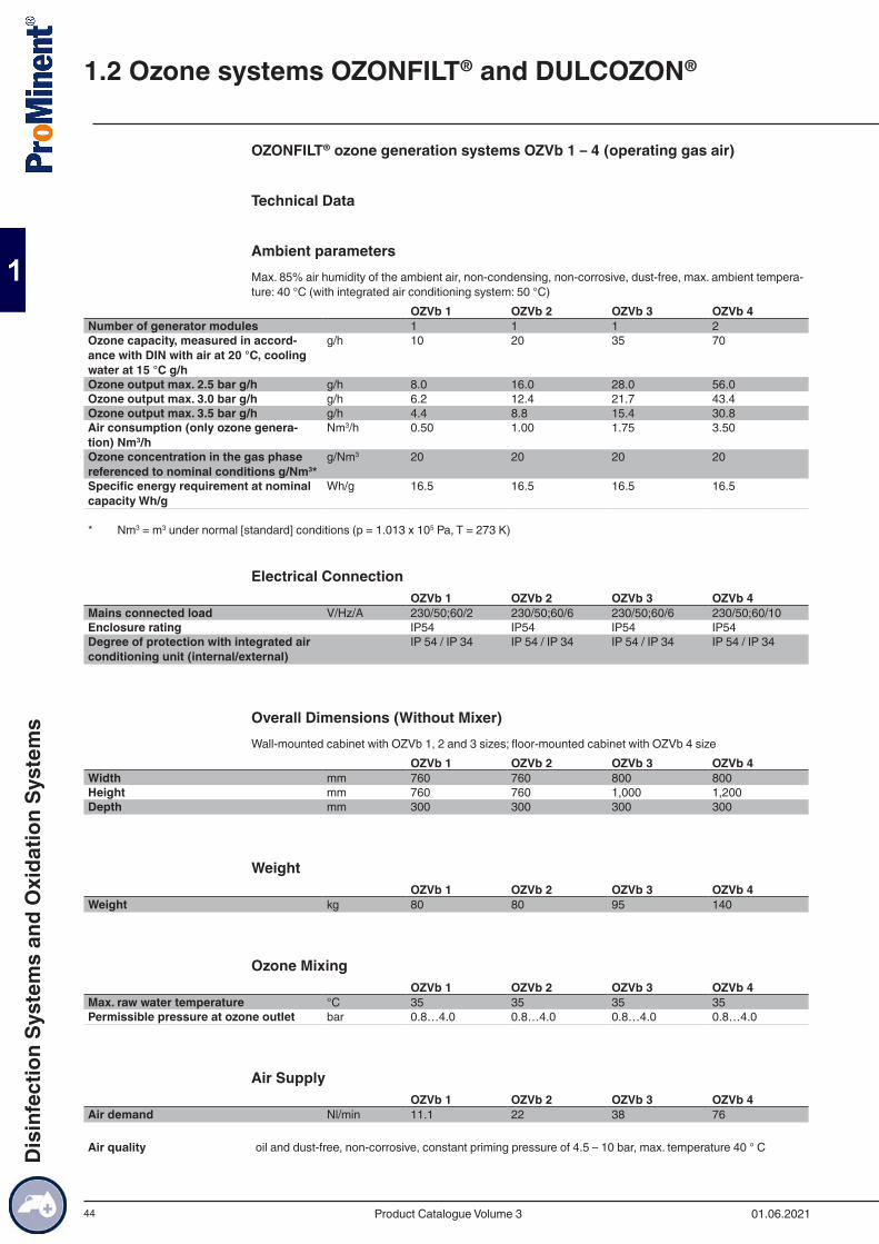
44
OZONFILT® ozone generation systems OZVb 1 – 4 (operating gas air)
Technical Data
Ambient parametersMax. 85% air humidity of the ambient air, non-condensing, non-corrosive, dust-free, max. ambient tempera-ture: 40 °C (with integrated air conditioning system: 50 °C)
OZVb 1 OZVb 2 OZVb 3 OZVb 4Number of generator modules 1 1 1 2Ozone capacity, measured in accord-ance with DIN with air at 20 °C, cooling water at 15 °C g/h
g/h 10 20 35 70
Ozone output max. 2.5 bar g/h g/h 8.0 16.0 28.0 56.0Ozone output max. 3.0 bar g/h g/h 6.2 12.4 21.7 43.4Ozone output max. 3.5 bar g/h g/h 4.4 8.8 15.4 30.8Air consumption (only ozone genera-tion) Nm3/h
Nm3/h 0.50 1.00 1.75 3.50
Ozone concentration in the gas phase referenced to nominal conditions g/Nm3*
g/Nm3 20 20 20 20
Specific energy requirement at nominal capacity Wh/g
Wh/g 16.5 16.5 16.5 16.5
* Nm3 = m3 under normal [standard] conditions (p = 1.013 x 10⁵ Pa, T = 273 K)
Electrical ConnectionOZVb 1 OZVb 2 OZVb 3 OZVb 4
Mains connected load V/Hz/A 230/50;60/2 230/50;60/6 230/50;60/6 230/50;60/10Enclosure rating IP54 IP54 IP54 IP54Degree of protection with integrated air conditioning unit (internal/external)
IP 54 / IP 34 IP 54 / IP 34 IP 54 / IP 34 IP 54 / IP 34
Overall Dimensions (Without Mixer)Wall-mounted cabinet with OZVb 1, 2 and 3 sizes; floor-mounted cabinet with OZVb 4 size
OZVb 1 OZVb 2 OZVb 3 OZVb 4Width mm 760 760 800 800Height mm 760 760 1,000 1,200Depth mm 300 300 300 300
WeightOZVb 1 OZVb 2 OZVb 3 OZVb 4
Weight kg 80 80 95 140
Ozone MixingOZVb 1 OZVb 2 OZVb 3 OZVb 4
Max. raw water temperature °C 35 35 35 35Permissible pressure at ozone outlet bar 0.8…4.0 0.8…4.0 0.8…4.0 0.8…4.0
Air SupplyOZVb 1 OZVb 2 OZVb 3 OZVb 4
Air demand Nl/min 11.1 22 38 76
Air quality oil and dust-free, non-corrosive, constant priming pressure of 4.5 – 10 bar, max. temperature 40 ° C
1.2 Ozone systems OZONFILT® and DULCOZON®
01.06.2021Product Catalogue Volume 3
Dis
infe
ctio
n Sy
stem
s an
d O
xida
tion
Syst
ems
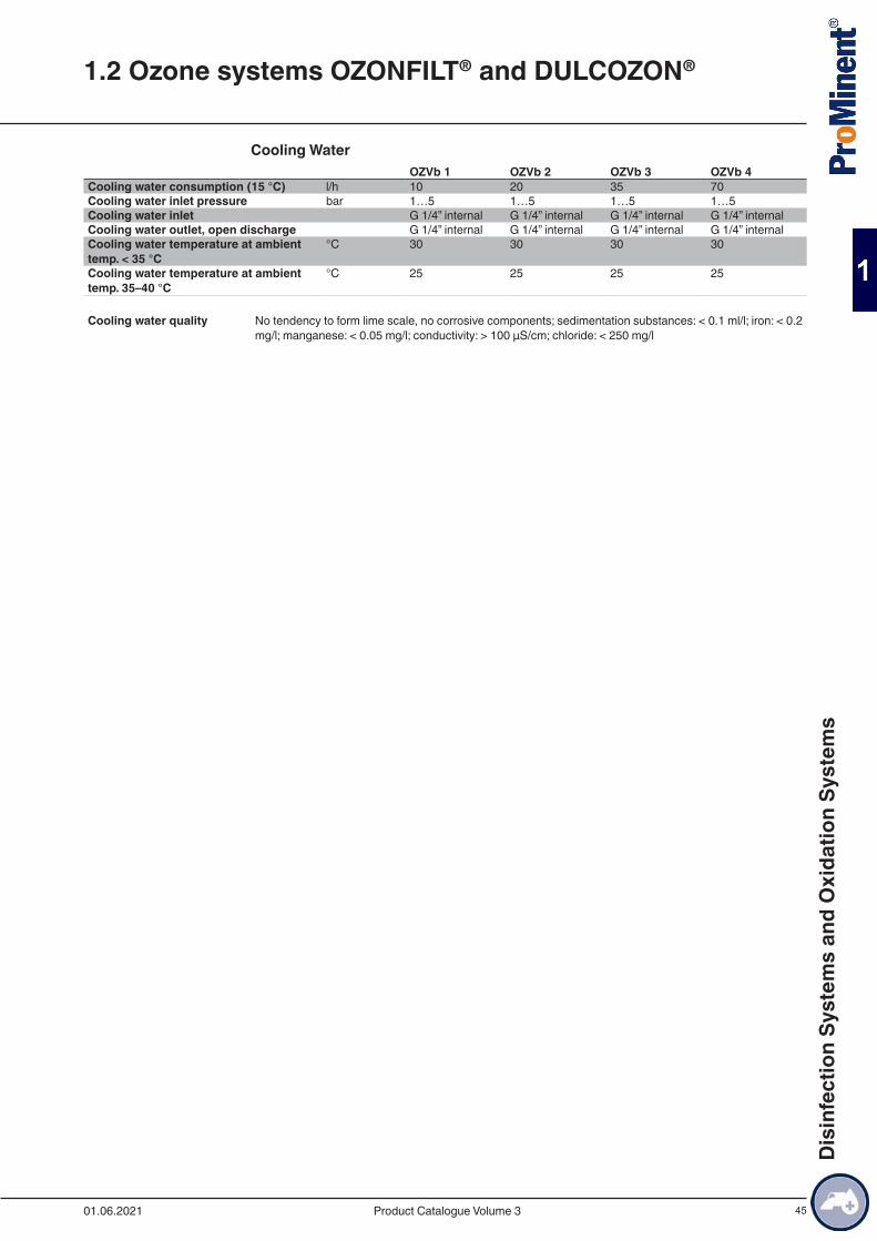
45
Cooling WaterOZVb 1 OZVb 2 OZVb 3 OZVb 4
Cooling water consumption (15 °C) l/h 10 20 35 70Cooling water inlet pressure bar 1…5 1…5 1…5 1…5Cooling water inlet G 1/4” internal G 1/4” internal G 1/4” internal G 1/4” internalCooling water outlet, open discharge G 1/4” internal G 1/4” internal G 1/4” internal G 1/4” internalCooling water temperature at ambient temp. < 35 °C
°C 30 30 30 30
Cooling water temperature at ambient temp. 35–40 °C
°C 25 25 25 25
Cooling water quality No tendency to form lime scale, no corrosive components; sedimentation substances: < 0.1 ml/l; iron: < 0.2 mg/l; manganese: < 0.05 mg/l; conductivity: > 100 µS/cm; chloride: < 250 mg/l
1.2 Ozone systems OZONFILT® and DULCOZON®
01.06.2021 Product Catalogue Volume 3
Dis
infe
ctio
n Sy
stem
s an
d O
xida
tion
Syst
ems
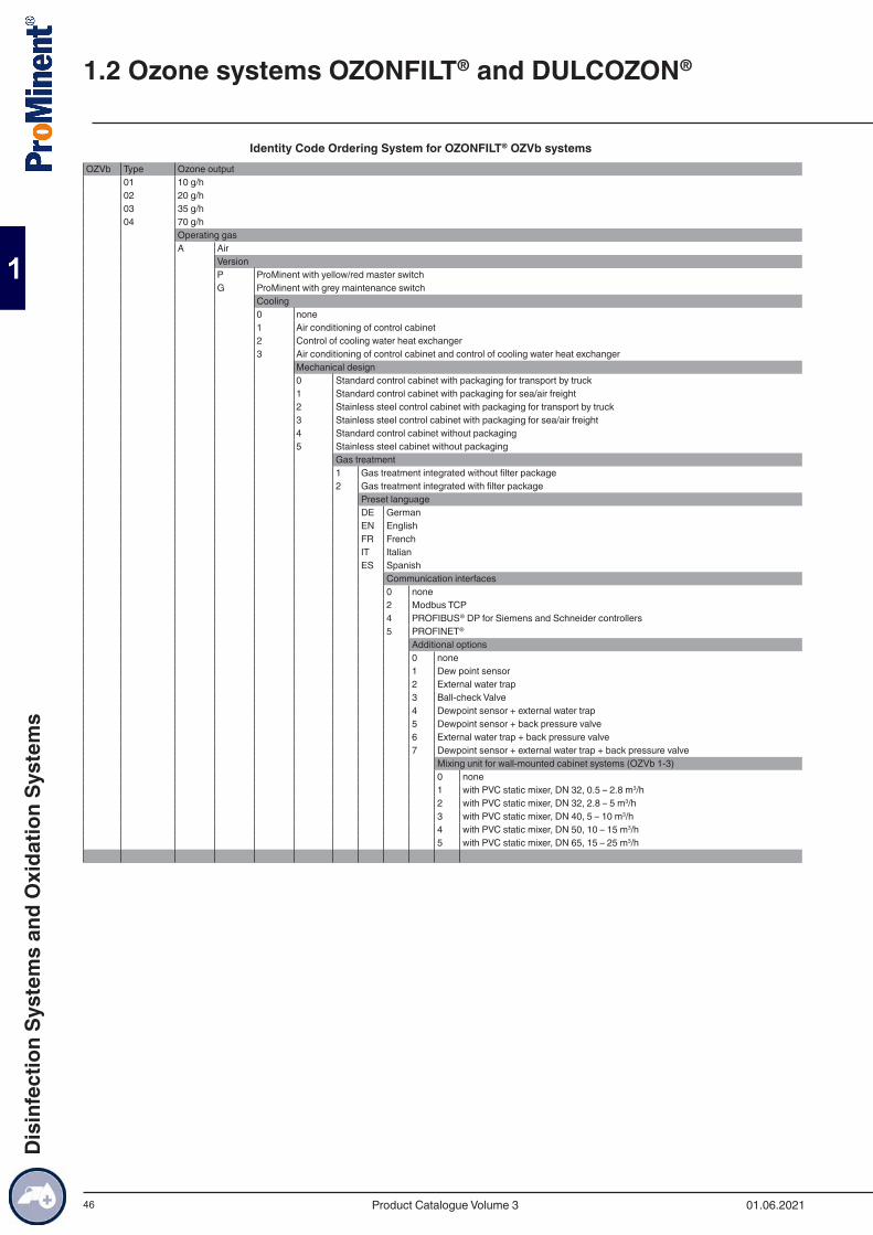
46
Identity Code Ordering System for OZONFILT® OZVb systemsOZVb Type Ozone output
01 10 g/h02 20 g/h03 35 g/h04 70 g/h
Operating gasA Air
VersionP ProMinent with yellow/red master switchG ProMinent with grey maintenance switch
Cooling0 none1 Air conditioning of control cabinet2 Control of cooling water heat exchanger3 Air conditioning of control cabinet and control of cooling water heat exchanger
Mechanical design0 Standard control cabinet with packaging for transport by truck1 Standard control cabinet with packaging for sea/air freight2 Stainless steel control cabinet with packaging for transport by truck3 Stainless steel control cabinet with packaging for sea/air freight4 Standard control cabinet without packaging5 Stainless steel cabinet without packaging
Gas treatment1 Gas treatment integrated without filter package2 Gas treatment integrated with filter package
Preset languageDE GermanEN EnglishFR FrenchIT ItalianES Spanish
Communication interfaces0 none2 Modbus TCP4 PROFIBUS® DP for Siemens and Schneider controllers5 PROFINET®
Additional options0 none1 Dew point sensor2 External water trap3 Ball-check Valve4 Dewpoint sensor + external water trap5 Dewpoint sensor + back pressure valve6 External water trap + back pressure valve7 Dewpoint sensor + external water trap + back pressure valve
Mixing unit for wall-mounted cabinet systems (OZVb 1-3)0 none1 with PVC static mixer, DN 32, 0.5 – 2.8 m3/h2 with PVC static mixer, DN 32, 2.8 – 5 m3/h3 with PVC static mixer, DN 40, 5 – 10 m3/h4 with PVC static mixer, DN 50, 10 – 15 m3/h5 with PVC static mixer, DN 65, 15 – 25 m3/h
1.2 Ozone systems OZONFILT® and DULCOZON®
01.06.2021Product Catalogue Volume 3
Dis
infe
ctio
n Sy
stem
s an
d O
xida
tion
Syst
ems
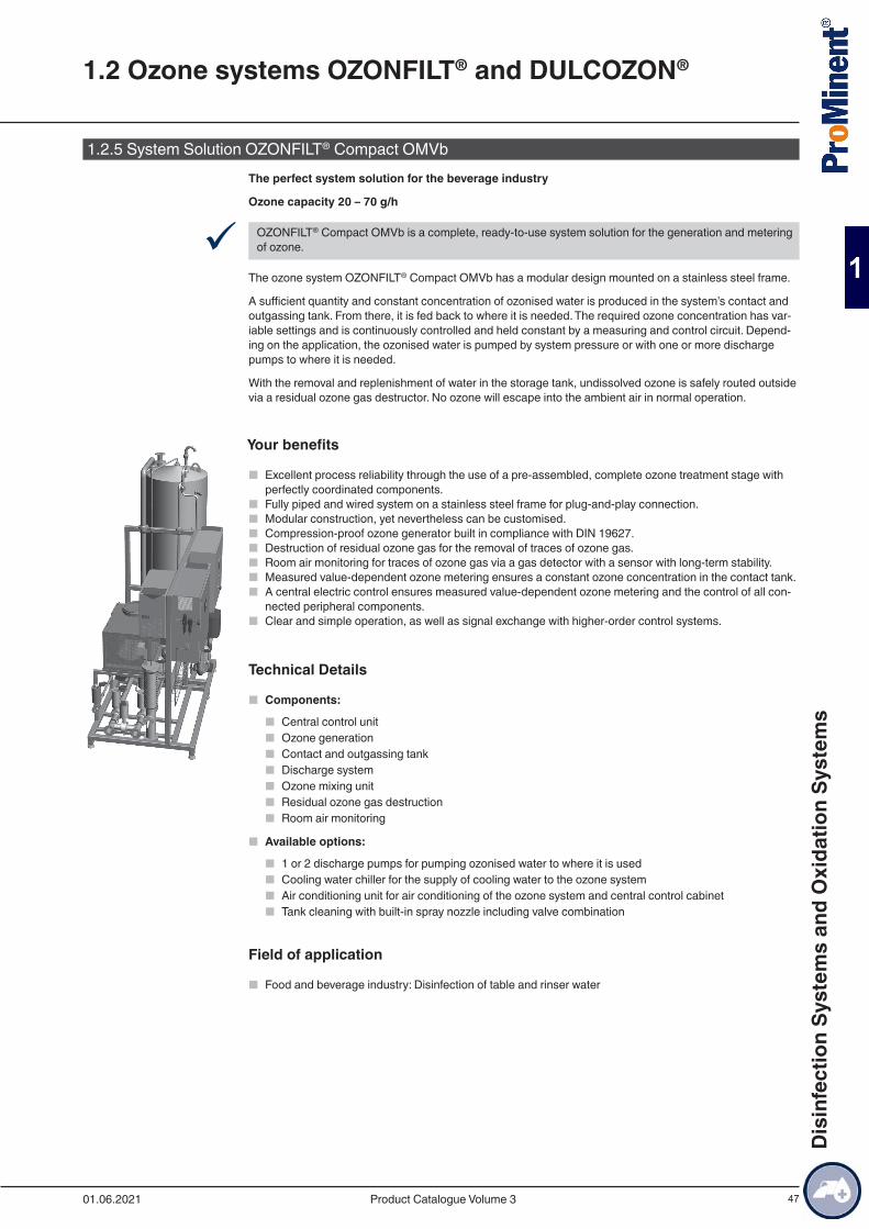
47
1.2.5 System Solution OZONFILT® Compact OMVbThe perfect system solution for the beverage industry
Ozone capacity 20 – 70 g/h
9 OZONFILT® Compact OMVb is a complete, ready-to-use system solution for the generation and metering of ozone.
The ozone system OZONFILT® Compact OMVb has a modular design mounted on a stainless steel frame.
A sufficient quantity and constant concentration of ozonised water is produced in the system’s contact and outgassing tank. From there, it is fed back to where it is needed. The required ozone concentration has var-iable settings and is continuously controlled and held constant by a measuring and control circuit. Depend-ing on the application, the ozonised water is pumped by system pressure or with one or more discharge pumps to where it is needed.
With the removal and replenishment of water in the storage tank, undissolved ozone is safely routed outside via a residual ozone gas destructor. No ozone will escape into the ambient air in normal operation.
Your benefits
■ Excellent process reliability through the use of a pre-assembled, complete ozone treatment stage with perfectly coordinated components.
■ Fully piped and wired system on a stainless steel frame for plug-and-play connection. ■ Modular construction, yet nevertheless can be customised. ■ Compression-proof ozone generator built in compliance with DIN 19627. ■ Destruction of residual ozone gas for the removal of traces of ozone gas. ■ Room air monitoring for traces of ozone gas via a gas detector with a sensor with long-term stability. ■ Measured value-dependent ozone metering ensures a constant ozone concentration in the contact tank. ■ A central electric control ensures measured value-dependent ozone metering and the control of all con-
nected peripheral components. ■ Clear and simple operation, as well as signal exchange with higher-order control systems.
Technical Details
■ Components:
■ Central control unit ■ Ozone generation ■ Contact and outgassing tank ■ Discharge system ■ Ozone mixing unit ■ Residual ozone gas destruction ■ Room air monitoring
■ Available options:
■ 1 or 2 discharge pumps for pumping ozonised water to where it is used ■ Cooling water chiller for the supply of cooling water to the ozone system ■ Air conditioning unit for air conditioning of the ozone system and central control cabinet ■ Tank cleaning with built-in spray nozzle including valve combination
Field of application
■ Food and beverage industry: Disinfection of table and rinser water
1.2 Ozone systems OZONFILT® and DULCOZON®
01.06.2021 Product Catalogue Volume 3
Dis
infe
ctio
n Sy
stem
s an
d O
xida
tion
Syst
ems

48
Technical DataType TWA for fillerType OMVb TWA 20 –
1000OMVb TWA 35 – 1000
OMVb TWA 70 – 2000
Type ozone generator OZVb 2 OZVb 3 OZVb 4Reaction tank volume l 1,000 1,000 2,000Ozone output at 20 g/Nm3 g/h 20 35 70Nominal flow rate m3/h 5…15 15…30 45…60Enclosure rating IP54 IP54 IP54
Type RI for rinser applicationsType OMVb RI 20 – 500Type ozone generator OZVb 2Reaction tank volume l 500Ozone output at 20 g/Nm3 g/h 20Nominal flow rate m3/h 5…15Enclosure rating IP54
1.2 Ozone systems OZONFILT® and DULCOZON®
01.06.2021Product Catalogue Volume 3
Dis
infe
ctio
n Sy
stem
s an
d O
xida
tion
Syst
ems
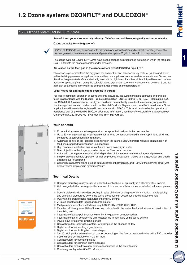
49
1.2.6 Ozone System OZONFILT® OZMa Powerful and yet environmentally-friendly. Disinfect and oxidise ecologically and economically.
Ozone capacity 70 – 420 g ozone/h
9 OZONFILT® OZMa is synonymous with maximum operational safety and minimal operating costs. The ozone generator is maintenance-free and generates up to 420 g/h of ozone from compressed air.
The ozone systems OZONFILT® OZMa have been designed as pressurised systems, in which the feed gas – air – is fed into the ozone generator under pressure.
Air is used as the feed gas in the ozone system Ozonfilt®OZMaA type 1 to 6
The ozone is generated from the oxygen in the ambient air and simultaneously metered. A demand-driven, self-optimising pressure swing dryer reduces the consumption of compressed air to a minimum. Ozone can therefore be generated safely and reliably even with a high level of ambient air humidity with ozone concen-trations of up to 20 g/Nm3. Using the suitable mixing equipment, ozone concentrations of between 3 and 12 ppm can be achieved in the water to be treated, depending on the temperature.
Legal notice for operating ozone systems in Europe:
For legally compliant operation of ozone systems in Europe, the system must be approved and/or regis-tered in accordance with the Biocidal Products Regulation (EU) No. 528/2012 or REACH Regulation (EU) No. 1907/2006. As a member of EurO3zon, ProMinent automatically provides the necessary approval for biocidal applications in accordance with the Biocidal Products Regulation on behalf of its customers. Other applications will have to be registered in accordance with REACH. This must be done by the operator but assistance can be provided by EurO3zon. For more information, see https://www.prominent.de/resources/Other/German/26231/20210216-Kunden-Info-BPR-REACH.pdf.
Your benefits
■ Economical: maintenance-free generator concept with virtually unlimited service life ■ Up to 30% energy savings for air treatment, thanks to demand-controlled and self-optimising air drying
compared to conventional air treatment. ■ Automatic control of the feed gas depending on the ozone output, therefore reduced consumption of
feed gas produced with intensive use of energy. ■ High ozone concentration ensures optimum ozone solubility in water ■ Direct injection without injector system for up to 2 bar back pressure ■ Automatic ozone generation, virtually independent of fluctuations in mains voltage and pressure ■ Simple, safe and reliable operation as well as process visualisation thanks to a large, colour and clearly
arranged 6.5” touch panel ■ Continuous adjustment and precise output control of between 3% and 100% of the nominal power with
ozone volume displayed in “grammes/hour”
Technical Details
■ Compact mounting, ready-to-use in a painted steel cabinet or optionally in a stainless steel cabinet ■ With integrated filter package for the removal of dust and small amounts of residual oil in the compressed
air ■ Special dielectric with excellent cooling: in spite of the low cooling water consumption, heat is quickly
and efficiently discharged before the ozone produced can decompose due to excessive heat. ■ PLC with integrated ozone measurement and PID control ■ 7” touch panel with data logger and screen plotter ■ Multiple communications interfaces (e.g. LAN, Profibus® DP, ISDN, TCP) ■ Excellent efficiency: over 90% of the ozone is dissolved in the water thanks to the special construction of
the mixing unit. ■ Integration of a dew point sensor to monitor the quality of compressed air ■ Integration of an air conditioning unit to adjust the temperature of the ozone system ■ Pause input for external switching on/off ■ Contact input for locking the system, for example in the absence of flow ■ Digital input for connecting a gas detector ■ Digital input for controlling two power stages ■ 0/4-20 mA input for external output control depending on the flow or measured value with a PIC controller ■ Second freely configurable 0/ 4-20 mA input ■ Contact output for operating status ■ Contact output for common alarm message ■ Contact output for limit violation, ozone concentration in the water too low ■ One freely configurable 0/ 4-20 mA output
1.2 Ozone systems OZONFILT® and DULCOZON®
01.06.2021 Product Catalogue Volume 3
Dis
infe
ctio
n Sy
stem
s an
d O
xida
tion
Syst
ems

50
Field of application
■ Potable water supply: Oxidation of iron, manganese and arsenic, refinement and taste enhancement and disinfection
■ Waste water treatment: Degradation/reduction of COD and microcontaminants, reduction of sewage sludge
■ Food and beverage industry: Oxidation of iron and manganese, disinfection of potable water and rinser water
■ Swimming pools: Degradation of disinfection by-products, reliable microbiological barrier and produc-tion of crystal-clear water thanks to its microflocculating effect
■ Industry: Legionella prevention and disinfection of cooling water
1.2 Ozone systems OZONFILT® and DULCOZON®
01.06.2021Product Catalogue Volume 3
Dis
infe
ctio
n Sy
stem
s an
d O
xida
tion
Syst
ems
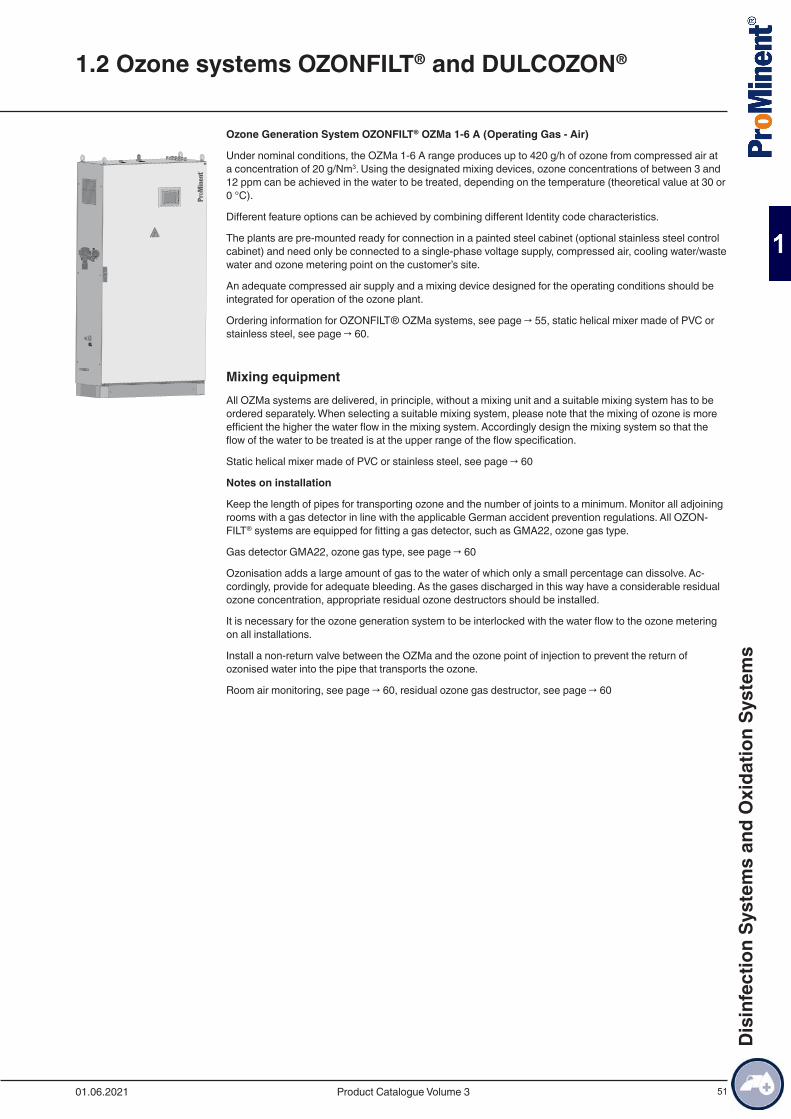
51
Ozone Generation System OZONFILT® OZMa 1-6 A (Operating Gas - Air)
Under nominal conditions, the OZMa 1-6 A range produces up to 420 g/h of ozone from compressed air at a concentration of 20 g/Nm3. Using the designated mixing devices, ozone concentrations of between 3 and 12 ppm can be achieved in the water to be treated, depending on the temperature (theoretical value at 30 or 0 °C).
Different feature options can be achieved by combining different Identity code characteristics.
The plants are pre-mounted ready for connection in a painted steel cabinet (optional stainless steel control cabinet) and need only be connected to a single-phase voltage supply, compressed air, cooling water/waste water and ozone metering point on the customer’s site.
An adequate compressed air supply and a mixing device designed for the operating conditions should be integrated for operation of the ozone plant.
Ordering information for OZONFILT® OZMa systems, see page → 55, static helical mixer made of PVC or stainless steel, see page → 60.
Mixing equipmentAll OZMa systems are delivered, in principle, without a mixing unit and a suitable mixing system has to be ordered separately. When selecting a suitable mixing system, please note that the mixing of ozone is more efficient the higher the water flow in the mixing system. Accordingly design the mixing system so that the flow of the water to be treated is at the upper range of the flow specification.
Static helical mixer made of PVC or stainless steel, see page → 60
Notes on installation
Keep the length of pipes for transporting ozone and the number of joints to a minimum. Monitor all adjoining rooms with a gas detector in line with the applicable German accident prevention regulations. All OZON-FILT® systems are equipped for fitting a gas detector, such as GMA22, ozone gas type.
Gas detector GMA22, ozone gas type, see page → 60
Ozonisation adds a large amount of gas to the water of which only a small percentage can dissolve. Ac-cordingly, provide for adequate bleeding. As the gases discharged in this way have a considerable residual ozone concentration, appropriate residual ozone destructors should be installed.
It is necessary for the ozone generation system to be interlocked with the water flow to the ozone metering on all installations.
Install a non-return valve between the OZMa and the ozone point of injection to prevent the return of ozonised water into the pipe that transports the ozone.
Room air monitoring, see page → 60, residual ozone gas destructor, see page → 60
1.2 Ozone systems OZONFILT® and DULCOZON®
01.06.2021 Product Catalogue Volume 3
Dis
infe
ctio
n Sy
stem
s an
d O
xida
tion
Syst
ems

52
Technical Data
Ozone Generation Systems OZONFILT® OZMa 1-3 A (Process Gas - Air)
Ambient parametersMax. 85% air humidity of the ambient air, non-condensing, non-corrosive, dust-free, max. ambient tempera-ture: 40 °C (with integrated air conditioning system: 50 °C)
OZMa 1A OZMa 2A OZMa 3ANumber of generator modules 1 1 1Ozone capacity, measured in accordance with DIN with air at 20 °C, cooling water at 15 °C
g/h 70 105 140
Air consumption (only ozone generation) Nm3/h 3.50 5.25 7.00Ozone concentration in the gas phase referenced to nom-inal conditions
g/Nm3 20 20 20
Specific energy requirement at nominal capacity Wh/g 16.5 16.5 16.5Power factor at full capacity cos φ 0.95 0.95 0.95Ozone connection Rp 3/8” Rp 3/8” Rp 3/8”
Electrical ConnectionOZMa 1A OZMa 2A OZMa 3A
Mains connected load V/Hz/A V/Hz/A 230/50;60/10 230/50;60/16 230/50;60/16Enclosure rating IP54 IP54 IP54Degree of protection with integrated air conditioning unit (internal/external)
IP 54 / IP 34 IP 54 / IP 34 IP 54 / IP 34
Overall Dimensions (Without Mixer)OZMa 1A OZMa 2A OZMa 3A
Width mm 1,114 1,114 1,114Height mm 1,961 1,961 1,961Depth mm 405 405 405
WeightOZMa 1A OZMa 2A OZMa 3A
Weight kg 270 280 300
Ozone MixingOZMa 1A OZMa 2A OZMa 3A
Max. raw water temperature °C 35 35 35Permissible pressure at ozone outlet bar 0.8…2.0 0.8…2.0 0.8…2.0
Air SupplyOZMa 1A OZMa 2A OZMa 3A
Air demand Nl/min 73 110 147
Air quality oil and dust-free, non-corrosive, constant priming pressure of 4.5 – 10 bar, max. temperature 40 ° C
1.2 Ozone systems OZONFILT® and DULCOZON®
01.06.2021Product Catalogue Volume 3
Dis
infe
ctio
n Sy
stem
s an
d O
xida
tion
Syst
ems

53
Cooling WaterOZMa 1A OZMa 2A OZMa 3A
Cooling water consumption (15 °C) l/h 90 135 180Cooling water consumption (30 °C) l/h 125 190 250Cooling water inlet pressure bar 2…5 2…5 2…5Cooling water outlet, open discharge mm 8 x 5 8 x 5 12 x 9Cooling water inlet, PE pressure hose mm 8 x 5 8 x 5 12 x 9
Cooling water quality No tendency to form lime scale, no corrosive components; sedimentation substances: < 0.1 ml/l; iron: < 0.2 mg/l; manganese: < 0.05 mg/l; conductivity: > 100 µS/cm; chloride: < 250 mg/l
Ozone Generation Systems OZONFILT® OZMa 4-6 A (Process Gas - Air)
Ambient parametersMax. 85% air humidity of the ambient air, non-condensing, non-corrosive, dust-free, max. ambient tempera-ture: 40 °C (with integrated air conditioning system: 50 °C)
OZMa 4A OZMa 5A OZMa 6ANumber of generator modules 2 2 3Ozone capacity, measured in accordance with DIN with air at 20 °C, cooling water at 15 °C
g/h 210 280 420
Air consumption (only ozone generation) Nm3/h 10.50 14.00 21.00Ozone concentration in the gas phase referenced to nom-inal conditions*
g/Nm3 20 20 20
Specific energy requirement at nominal capacity Wh/g 16.5 16.5 16.5Power factor at full capacity cos φ 0.95 0.95 0.95Ozone connection Rp 3/8” Rp 3/8” Rp 3/8”
* Nm3 = m3 under normal [standard] conditions (p = 1.013 x 10⁵ Pa, T = 273 K)
Electrical ConnectionOZMa 4A OZMa 5A OZMa 6A
Mains connected load V/Hz/A V/Hz/A 400/50;60/16 400/50;60/16 400/50;60/16Enclosure rating IP54 IP54 IP54Degree of protection with integrated air conditioning unit (internal/external)
IP 54 / IP 34 IP 54 / IP 34 IP 54 / IP 34
Overall Dimensions (Without Mixer)OZMa 4A OZMa 5A OZMa 6A
Width mm 1,320 1,320 1,606Height mm 1,961 1,961 1,961Depth mm 605 605 605
WeightOZMa 4A OZMa 5A OZMa 6A
Weight kg 420 445 580
1.2 Ozone systems OZONFILT® and DULCOZON®
01.06.2021 Product Catalogue Volume 3
Dis
infe
ctio
n Sy
stem
s an
d O
xida
tion
Syst
ems
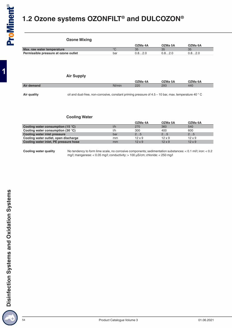
54
Ozone MixingOZMa 4A OZMa 5A OZMa 6A
Max. raw water temperature °C 35 35 35Permissible pressure at ozone outlet bar 0.8…2.0 0.8…2.0 0.8…2.0
Air SupplyOZMa 4A OZMa 5A OZMa 6A
Air demand Nl/min 220 293 440
Air quality oil and dust-free, non-corrosive, constant priming pressure of 4.5 – 10 bar, max. temperature 40 ° C
Cooling WaterOZMa 4A OZMa 5A OZMa 6A
Cooling water consumption (15 °C) l/h 270 360 540Cooling water consumption (30 °C) l/h 300 400 600Cooling water inlet pressure bar 2…5 2…5 2…5Cooling water outlet, open discharge mm 12 x 9 12 x 9 12 x 9Cooling water inlet, PE pressure hose mm 12 x 9 12 x 9 12 x 9
Cooling water quality No tendency to form lime scale, no corrosive components; sedimentation substances: < 0.1 ml/l; iron: < 0.2 mg/l; manganese: < 0.05 mg/l; conductivity: > 100 µS/cm; chloride: < 250 mg/l
1.2 Ozone systems OZONFILT® and DULCOZON®
01.06.2021Product Catalogue Volume 3
Dis
infe
ctio
n Sy
stem
s an
d O
xida
tion
Syst
ems
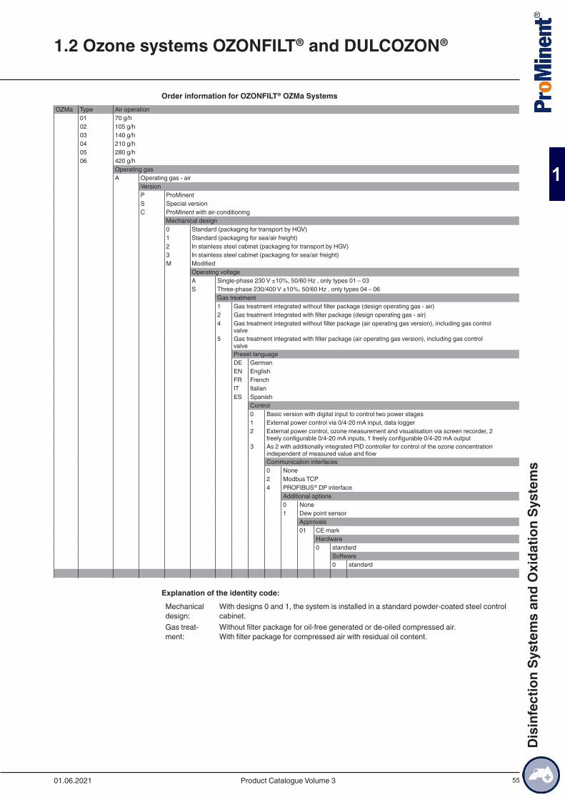
55
Order information for OZONFILT® OZMa SystemsOZMa Type Air operation
01 70 g/h02 105 g/h03 140 g/h04 210 g/h05 280 g/h06 420 g/h
Operating gasA Operating gas - air
VersionP ProMinentS Special versionC ProMinent with air-conditioning
Mechanical design0 Standard (packaging for transport by HGV)1 Standard (packaging for sea/air freight)2 In stainless steel cabinet (packaging for transport by HGV)3 In stainless steel cabinet (packaging for sea/air freight)M Modified
Operating voltageA Single-phase 230 V ±10%, 50/60 Hz , only types 01 – 03S Three-phase 230/400 V ±10%, 50/60 Hz , only types 04 – 06
Gas treatment1 Gas treatment integrated without filter package (design operating gas - air)2 Gas treatment integrated with filter package (design operating gas - air)4 Gas treatment integrated without filter package (air operating gas version), including gas control
valve5 Gas treatment integrated with filter package (air operating gas version), including gas control
valvePreset languageDE GermanEN EnglishFR FrenchIT ItalianES Spanish
Control0 Basic version with digital input to control two power stages1 External power control via 0/4-20 mA input, data logger2 External power control, ozone measurement and visualisation via screen recorder, 2
freely configurable 0/4-20 mA inputs, 1 freely configurable 0/4-20 mA output3 As 2 with additionally integrated PID controller for control of the ozone concentration
independent of measured value and flowCommunication interfaces0 None2 Modbus TCP4 PROFIBUS® DP interface
Additional options0 None1 Dew point sensor
Approvals01 CE mark
Hardware0 standard
Software0 standard
Explanation of the identity code:Mechanical design:
With designs 0 and 1, the system is installed in a standard powder-coated steel control cabinet.
Gas treat-ment:
Without filter package for oil-free generated or de-oiled compressed air. With filter package for compressed air with residual oil content.
1.2 Ozone systems OZONFILT® and DULCOZON®
01.06.2021 Product Catalogue Volume 3
Dis
infe
ctio
n Sy
stem
s an
d O
xida
tion
Syst
ems
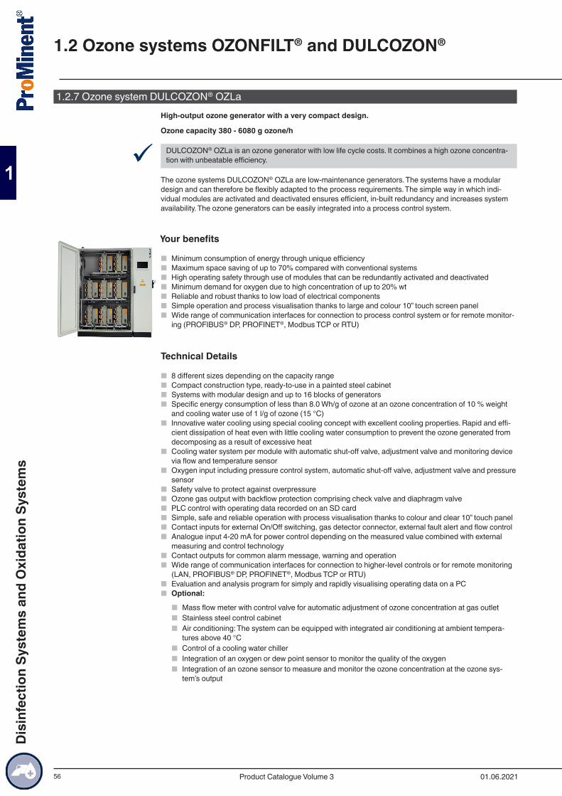
56
1.2.7 Ozone system DULCOZON® OZLaHigh-output ozone generator with a very compact design.
Ozone capacity 380 - 6080 g ozone/h
9 DULCOZON® OZLa is an ozone generator with low life cycle costs. It combines a high ozone concentra-tion with unbeatable efficiency.
The ozone systems DULCOZON® OZLa are low-maintenance generators. The systems have a modular design and can therefore be flexibly adapted to the process requirements. The simple way in which indi-vidual modules are activated and deactivated ensures efficient, in-built redundancy and increases system availability. The ozone generators can be easily integrated into a process control system.
Your benefits
■ Minimum consumption of energy through unique efficiency ■ Maximum space saving of up to 70% compared with conventional systems ■ High operating safety through use of modules that can be redundantly activated and deactivated ■ Minimum demand for oxygen due to high concentration of up to 20% wt ■ Reliable and robust thanks to low load of electrical components ■ Simple operation and process visualisation thanks to large and colour 10” touch screen panel ■ Wide range of communication interfaces for connection to process control system or for remote monitor-
ing (PROFIBUS® DP, PROFINET®, Modbus TCP or RTU)
Technical Details
■ 8 different sizes depending on the capacity range ■ Compact construction type, ready-to-use in a painted steel cabinet ■ Systems with modular design and up to 16 blocks of generators ■ Specific energy consumption of less than 8.0 Wh/g of ozone at an ozone concentration of 10 % weight
and cooling water use of 1 l/g of ozone (15 °C) ■ Innovative water cooling using special cooling concept with excellent cooling properties. Rapid and effi-
cient dissipation of heat even with little cooling water consumption to prevent the ozone generated from decomposing as a result of excessive heat
■ Cooling water system per module with automatic shut-off valve, adjustment valve and monitoring device via flow and temperature sensor
■ Oxygen input including pressure control system, automatic shut-off valve, adjustment valve and pressure sensor
■ Safety valve to protect against overpressure ■ Ozone gas output with backflow protection comprising check valve and diaphragm valve ■ PLC control with operating data recorded on an SD card ■ Simple, safe and reliable operation with process visualisation thanks to colour and clear 10” touch panel ■ Contact inputs for external On/Off switching, gas detector connector, external fault alert and flow control ■ Analogue input 4-20 mA for power control depending on the measured value combined with external
measuring and control technology ■ Contact outputs for common alarm message, warning and operation ■ Wide range of communication interfaces for connection to higher-level controls or for remote monitoring
(LAN, PROFIBUS® DP, PROFINET®, Modbus TCP or RTU) ■ Evaluation and analysis program for simply and rapidly visualising operating data on a PC ■ Optional:
■ Mass flow meter with control valve for automatic adjustment of ozone concentration at gas outlet ■ Stainless steel control cabinet ■ Air conditioning: The system can be equipped with integrated air conditioning at ambient tempera-
tures above 40 °C ■ Control of a cooling water chiller ■ Integration of an oxygen or dew point sensor to monitor the quality of the oxygen ■ Integration of an ozone sensor to measure and monitor the ozone concentration at the ozone sys-
tem’s output
1.2 Ozone systems OZONFILT® and DULCOZON®
01.06.2021Product Catalogue Volume 3
Dis
infe
ctio
n Sy
stem
s an
d O
xida
tion
Syst
ems

57
Field of application
■ Drinking water supply: Oxidation of iron, manganese and arsenic, refinement and taste enhancement and disinfection
■ Waste water treatment: Degradation / reduction of COD and microcontaminants, reduction of sewage sludge and disinfection
■ Aquaculture: Oxidation and disinfection during the treatment of water for fish farming ■ Textile industry: Oxidation of waste water and treatment of textile fibres ■ Industry: Cooling water disinfection and legionella prevention ■ Food and beverage industry: Oxidation of iron and manganese, disinfection of table water and rinser
water
1.2 Ozone systems OZONFILT® and DULCOZON®
01.06.2021 Product Catalogue Volume 3
Dis
infe
ctio
n Sy
stem
s an
d O
xida
tion
Syst
ems
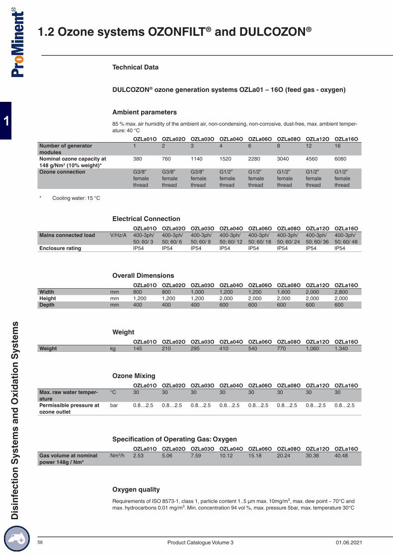
58
Technical Data
DULCOZON® ozone generation systems OZLa01 – 16O (feed gas - oxygen)
Ambient parameters85 % max. air humidity of the ambient air, non-condensing, non-corrosive, dust-free, max. ambient temper-ature: 40 °C
OZLa01O OZLa02O OZLa03O OZLa04O OZLa06O OZLa08O OZLa12O OZLa16ONumber of generator modules
1 2 3 4 6 8 12 16
Nominal ozone capacity at 148 g/Nm3 (10% weight)*
380 760 1140 1520 2280 3040 4560 6080
Ozone connection G3/8” female thread
G3/8” female thread
G3/8” female thread
G1/2” female thread
G1/2” female thread
G1/2” female thread
G1/2” female thread
G1/2” female thread
* Cooling water: 15 °C
Electrical ConnectionOZLa01O OZLa02O OZLa03O OZLa04O OZLa06O OZLa08O OZLa12O OZLa16O
Mains connected load V/Hz/A 400-3ph/ 50; 60/ 3
400-3ph/ 50; 60/ 6
400-3ph/ 50; 60/ 9
400-3ph/ 50; 60/ 12
400-3ph/ 50; 60/ 18
400-3ph/ 50; 60/ 24
400-3ph/ 50; 60/ 36
400-3ph/ 50; 60/ 48
Enclosure rating IP54 IP54 IP54 IP54 IP54 IP54 IP54 IP54
Overall DimensionsOZLa01O OZLa02O OZLa03O OZLa04O OZLa06O OZLa08O OZLa12O OZLa16O
Width mm 800 800 1,000 1,200 1,200 1,600 2,000 2,800Height mm 1,200 1,200 1,200 2,000 2,000 2,000 2,000 2,000Depth mm 400 400 400 600 600 600 600 600
WeightOZLa01O OZLa02O OZLa03O OZLa04O OZLa06O OZLa08O OZLa12O OZLa16O
Weight kg 145 210 295 410 540 770 1,060 1,340
Ozone MixingOZLa01O OZLa02O OZLa03O OZLa04O OZLa06O OZLa08O OZLa12O OZLa16O
Max. raw water temper-ature
°C 30 30 30 30 30 30 30 30
Permissible pressure at ozone outlet
bar 0.8…2.5 0.8…2.5 0.8…2.5 0.8…2.5 0.8…2.5 0.8…2.5 0.8…2.5 0.8…2.5
Specification of Operating Gas: OxygenOZLa01O OZLa02O OZLa03O OZLa04O OZLa06O OZLa08O OZLa12O OZLa16O
Gas volume at nominal power 148g / Nm3
Nm3/h 2.53 5.06 7.59 10.12 15.18 20.24 30.36 40.48
Oxygen qualityRequirements of ISO 8573-1, class 1, particle content 1..5 µm max. 10mg/m³, max. dew point – 70°C and max. hydrocarbons 0.01 mg/m³. Min. concentration 94 vol %, max. pressure 5bar, max. temperature 30°C
1.2 Ozone systems OZONFILT® and DULCOZON®
01.06.2021Product Catalogue Volume 3
Dis
infe
ctio
n Sy
stem
s an
d O
xida
tion
Syst
ems
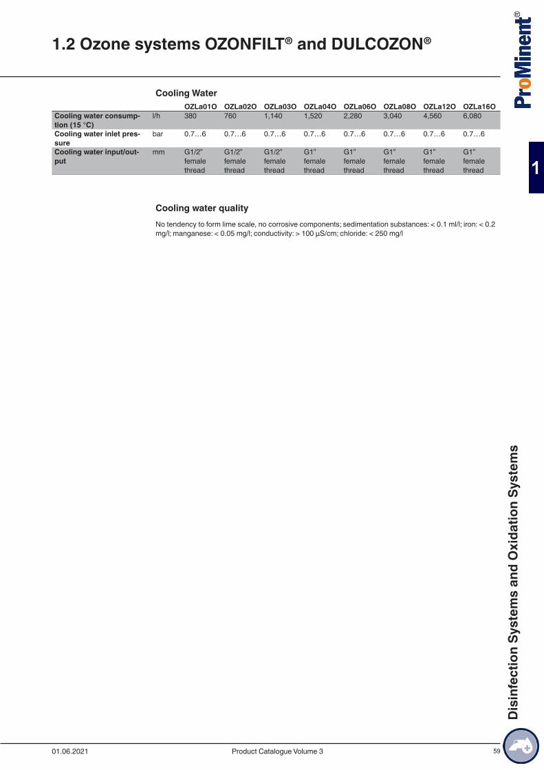
59
Cooling WaterOZLa01O OZLa02O OZLa03O OZLa04O OZLa06O OZLa08O OZLa12O OZLa16O
Cooling water consump-tion (15 °C)
l/h 380 760 1,140 1,520 2,280 3,040 4,560 6,080
Cooling water inlet pres-sure
bar 0.7…6 0.7…6 0.7…6 0.7…6 0.7…6 0.7…6 0.7…6 0.7…6
Cooling water input/out-put
mm G1/2” female thread
G1/2” female thread
G1/2” female thread
G1” female thread
G1” female thread
G1” female thread
G1” female thread
G1” female thread
Cooling water qualityNo tendency to form lime scale, no corrosive components; sedimentation substances: < 0.1 ml/l; iron: < 0.2 mg/l; manganese: < 0.05 mg/l; conductivity: > 100 µS/cm; chloride: < 250 mg/l
1.2 Ozone systems OZONFILT® and DULCOZON®
01.06.2021 Product Catalogue Volume 3
Dis
infe
ctio
n Sy
stem
s an
d O
xida
tion
Syst
ems
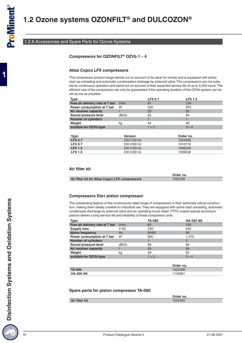
60
1.2.8 Accessories and Spare Parts for Ozone Systems
Compressors for OZONFILT® OZVb 1 – 4
Atlas Copco LFX compressorsThis compressor product range stands out on account of its value for money and is equipped with active start-up unloading and automatic condensation drainage by solenoid valve. The compressors are not suita-ble for continuous operation and stand out on account of their expected service life of up to 5,000 hours. The efficient use of the compressor can only be guaranteed if the operating duration of the OZVb system can be set as low as possible.Type LFX 0.7 LFX 1.5Free air delivery rate at 7 bar l/min 61 124Power consumption at 7 bar W 530 970Air receiver capacity l 20 20Sound pressure level dB(A) 62 64Number of cylinders 1 1Weight kg 44 48suitable for OZVb type 1 + 2 3 + 4
Type Version Order no.LFX 0.7 230 V/50 Hz 1004458LFX 0.7 230 V/60 Hz 1010719LFX 1.5 230 V/50 Hz 1006343LFX 1.5 230 V/60 Hz 1009638
Air filter kitOrder no.
Air filter kit for Atlas Copco LFX compressors 1005789
Compressors Dürr piston compressorThe outstanding feature of this continuously rated range of compressors is their extremely robust construc-tion, making them ideally suitable for industrial use. They are equipped with active start unloading, automatic condensate discharge by solenoid valve and an operating hours meter. PTFE coated special aluminium pistons deliver a long service life and reliability of these compressor units.Type TA-080 HA-200 AKFree air delivery rate at 7 bar l/min 62 120Supply max. V AC 230 230Mains frequency Hz 50/60 50Power consumption at 7 bar W 800 1,370Number of cylinders 1 2Sound pressure level dB(A) 68 69Air receiver capacity l 25 55Weight kg 49 62suitable for OZVb type 1 + 2 3 + 4
Order no.TA-080 1025398HA-200 AK 1105981
Spare parts for piston compressor TA-080Order no.
Air filter kit 1025400
1.2 Ozone systems OZONFILT® and DULCOZON®
01.06.2021Product Catalogue Volume 3
Dis
infe
ctio
n Sy
stem
s an
d O
xida
tion
Syst
ems

61
Spare parts for piston compressor HA 200 AKOrder no.
Air filter kit; 1 no. needed per plunger 1105982Vibration damper set 1105983Cup seal and cylinder; 1 no. needed per plunger; replace after 8,000 hours of operation
1106034
Ozone gas distributor moduleThe ozone gas distribution module regulates the amount of ozone as is driven by demand for up to 6 points of injection. The ozone is automatically controlled to a constant setpoint or variably using an analogue signal. The measured value may be dependent on a measurement of ozone concentration, ORP or flow. The desired metering quantity per point of injection is entered via a touch panel and exactly and clearly shown on the display. Dissonant values are recognised by the intelligent control when entered.
Your benefits
■ Low investment costs thanks to gas distribution to up to 6 points of injection with one ozone generator ■ Wide ozone quantity control range for each point of injection of 5-45 l/min or 10-90 l/min (air systems: 6 -
54 g/h or 12 -108 g/h; oxygen systems 45 – 405 g/h or 90 – 810 g/h) ■ Simple operation and visualisation with a touch panel ■ Automatic control of ozone quantities by means of a constant setpoint or depending on measured value ■ Simple pneumatic and electric connection to the ozone system using matched units ■ The number of points of injection can be adjusted thanks to the modular system setup ■ Simple installation since all components are fitted on one panel
Technical Details
■ Unit with modular design and ozone gas distribution to up to 6 individual points of injection ■ Panel-mounted distributor with remote control cabinet ■ Simple, safe and reliable operation with process visualisation thanks to colour and clear 4.3” touch panel ■ Individual panel-mounted dosing lines, fitted with the following main components ■ Individual panel-mounted dosing lines, fitted with the following main components
■ Manual shut-off valve to insulate the dosing line during maintenance ■ Combined gas/flow quantity measurement with control valve ■ Pneumatic diaphragm valve for automatically shutting off the dosing line in stand-by mode
■ PLC control with operating data recorded on an SD card ■ Contact inputs for external On/Off switching and external fault alert ■ Analogue input 4-20 mA for controlling ozone quantities depending on the measured value combined
with external measuring and control technology ■ Contact outputs for common alarm message, warning and operation ■ Integration of an ozone sensor to measure and monitor the ozone concentration at the ozone system’s
output
Field of application
■ All applications needing several points of injection in their vicinity
Electrical ConnectionMains connected load Enclosure ratingV/Hz/A 230-1ph/ 50;60 V/Hz/A IP 55
Control range for feed chemicalProduct designation l/min [g/h at 20 g/Nm³] l/min [g/h at 150 g/Nm³]Size 1 control valve 5 – 45 l/min [6 – 54 g/h] 5 – 45 l/min [45 – 405 g/h]Size 2 control valve 10 – 90 l/min [12 – 108 g/h] 5 – 90 l/min [90 – 810 g/h]
Overall dimensions and weight
1.2 Ozone systems OZONFILT® and DULCOZON®
01.06.2021 Product Catalogue Volume 3
Dis
infe
ctio
n Sy
stem
s an
d O
xida
tion
Syst
ems
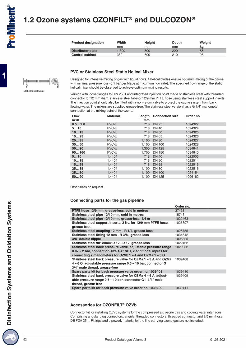
62
Product designation Width Height Depth Weight mm mm mm kgDistributor plate 1,300 500 220 55Control cabinet 380 600 210 25
PVC or Stainless Steel Static Helical MixerDesigned for intensive mixing of gas with liquid flows. 4 helical blades ensure optimum mixing of the ozone with minimal pressure loss (0.1 bar per blade at maximum flow rate). The specified flow range of the static helical mixer should be observed to achieve optimum mixing results.
Version with loose flanges to DIN 2501 and integrated injection point made of stainless steel with threaded connector for 12 mm diam. stainless steel tube or 12/9 mm PTFE hose using stainless steel support inserts. The injection point should also be fitted with a non-return valve to protect the ozone system from back flowing water. The mixers are supplied grease-free. The stainless steel version has a G 1/4” manometer connection at the mixing point of the ozone.Flow Material Length Connection size Order no.m3/h mm 0.5…2.8 PVC-U 718 DN 25 10943275…10 PVC-U 718 DN 40 102432410…15 PVC-U 718 DN 50 102432515…25 PVC-U 718 DN 65 102432625…35 PVC-U 1,100 DN 80 102432735…50 PVC-U 1,100 DN 100 102432850…90 PVC-U 1,300 DN 125 103464195…160 PVC-U 1,700 DN 150 10346405…10 1.4404 718 DN 40 102250310…15 1.4404 718 DN 50 102251415…25 1.4404 718 DN 65 102251525…35 1.4404 1,100 DN 80 102251635…50 1.4404 1,100 DN 100 102415450…90 1.4404 1,100 DN 125 1096162
Other sizes on request
Connecting parts for the gas pipelineOrder no.
PTFE hose 12/9 mm, grease-less, sold in metres 37428Stainless steel pipe 12/10 mm, sold in metres 15743Stainless steel pipe 12/10 mm, grease-less, 1.4 m 1022463Stainless steel support inserts, 2 No. for 12/9 mm PTFE hose, grease-less
1025397
Stainless steel coupling 12 mm - R 1/4, grease-less 1025755Stainless steel fitting 12 mm - R 3/8, grease-less 10346423/8” double nipple 1005825Stainless steel 90° elbow D 12 - D 12, grease-less 1022462Stainless steel back pressure valve, adjustable pressure range 0.07 – 2 bar, connection size 1/4” NPT, 2 additional inputs for connecting 2 manometers for OZVb 1 – 4 and OZMa 1 – 3 O
1029032
Stainless steel back pressure valve for OZMa 1 – 3 A and OZMa 4 – 6 O, adjustable pressure range 0.5 – 10 bar, connector G 3/4” male thread, grease-free
1039408
Spare parts kit for back pressure valve order no. 1039408 1039410Stainless steel back pressure valve for OZMa 4 – 6 A, adjust-able pressure range 0.5 – 10 bar, connector G 1 1/4” male thread, grease-free
1039409
Spare parts kit for back pressure valve order no. 1039409 1039411
Accessories for OZONFILT® OZVbConnector kit for installing OZVb systems for the compressed air, ozone gas and cooling water interfaces. Comprising angular plug connectors, angular threaded connectors, threaded connector and 8/5 mm hose DE FDA 35m. Fittings and pipework material for the line carrying ozone gas are not included.
Static Helical Mixer
1.2 Ozone systems OZONFILT® and DULCOZON®
01.06.2021Product Catalogue Volume 3
Dis
infe
ctio
n Sy
stem
s an
d O
xida
tion
Syst
ems
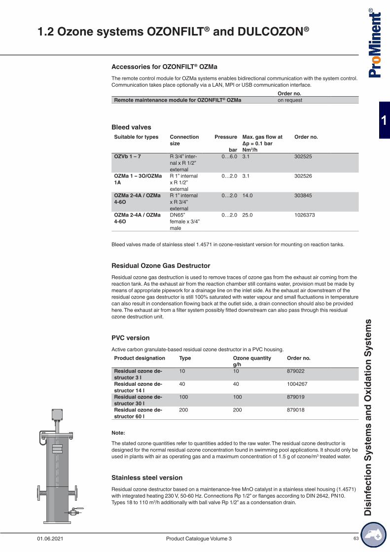
63
Accessories for OZONFILT® OZMaThe remote control module for OZMa systems enables bidirectional communication with the system control. Communication takes place optionally via a LAN, MPI or USB communication interface. Order no.Remote maintenance module for OZONFILT® OZMa on request
Bleed valvesSuitable for types Connection
sizePressure Max. gas flow at
Δp = 0.1 barOrder no.
bar Nm3/h OZVb 1 – 7 R 3/4” inter-
nal x R 1/2” external
0…6.0 3.1 302525
OZMa 1 – 3O/OZMa 1A
R 1” internal x R 1/2” external
0…2.0 3.1 302526
OZMa 2-4A / OZMa 4-6O
R 1” internal x R 3/4” external
0…2.0 14.0 303845
OZMa 2-4A / OZMa 4-6O
DN65” female x 3/4” male
0…2.0 25.0 1026373
Bleed valves made of stainless steel 1.4571 in ozone-resistant version for mounting on reaction tanks.
Residual Ozone Gas DestructorResidual ozone gas destruction is used to remove traces of ozone gas from the exhaust air coming from the reaction tank. As the exhaust air from the reaction chamber still contains water, provision must be made by means of appropriate pipework for a drainage line on the inlet side. As the exhaust air downstream of the residual ozone gas destructor is still 100% saturated with water vapour and small fluctuations in temperature can also result in condensation flowing back at the outlet side, a drain connection should also be provided here. The exhaust air from a filter system possibly fitted downstream can also pass through this residual ozone destruction unit.
PVC versionActive carbon granulate-based residual ozone destructor in a PVC housing.Product designation Type Ozone quantity Order no. g/h Residual ozone de-structor 3 l
10 10 879022
Residual ozone de-structor 14 l
40 40 1004267
Residual ozone de-structor 30 l
100 100 879019
Residual ozone de-structor 60 l
200 200 879018
Note:
The stated ozone quantities refer to quantities added to the raw water. The residual ozone destructor is designed for the normal residual ozone concentration found in swimming pool applications. It should only be used in plants with air as operating gas and a maximum concentration of 1.5 g of ozone/m3 treated water.
Stainless steel versionResidual ozone destructor based on a maintenance-free MnO catalyst in a stainless steel housing (1.4571) with integrated heating 230 V, 50-60 Hz. Connections Rp 1/2” or flanges according to DIN 2642, PN10. Types 18 to 110 m3/h additionally with ball valve Rp 1/2” as a condensation drain.
1.2 Ozone systems OZONFILT® and DULCOZON®
01.06.2021 Product Catalogue Volume 3
Dis
infe
ctio
n Sy
stem
s an
d O
xida
tion
Syst
ems
64
Max. gas flow Heating power
Dimensions H x W x D
Connection size Order no.
m3/h W mm 1.5 100 700 x 110 x
180Rp 1/2” 1018440
8.0 100 735 x 110 x 235
Rp 1/2” 1018406
18.0 140 1,154 x 275 x 240
DN 25 1019155
28.0 140 1,154 x 300 x 259
DN 25 1021037
40.0 500 1,156 x 330 x 264
DN 25 1026335
73.0 500 1,158 x 400 x 320
DN 32 1019971
110.0 500 1,160 x 450 x 375
DN 40 1027238
Note:
The catalytic residual ozone destructor should only be used in chlorine-free gas flows. The PVC version should therefore be used with swimming pool applications.
1.2 Ozone systems OZONFILT® and DULCOZON®
01.06.2021Product Catalogue Volume 3
Dis
infe
ctio
n Sy
stem
s an
d O
xida
tion
Syst
ems
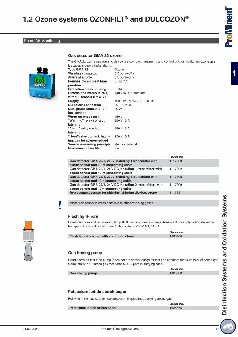
65
Room Air Monitoring
Gas detector GMA 22 ozoneThe GMA 22 ozone gas warning device is a compact measuring and control unit for monitoring ozone gas leakages in ozone installations.Type GMA 22 OzoneWarning at approx. 0.3 ppm/vol%Alarm at approx. 0.5 ppm/vol%Permissible ambient tem-perature
0...45 °C
Protection class housing IP 64Dimensions (without PGs, without sensor) H x W x D
140 x 97 x 50 mm mm
Supply 100 – 240 V AC / 50 – 60 HzDC power connection 20 - 30 V DCMax. power consumption incl. sensor
20 W
Warm-up phase max. 150 s“Warning” relay contact, latching
250 V ; 3 A
“Alarm” relay contact, latching
250 V ; 3 A
“Horn” relay contact, latch-ing, can be acknowledged
250 V ; 3 A
Sensor measuring principle electrochemical Maximum sensor life 2 a
Order no.Gas detector GMA 22/1, 230V including 1 transmitter with ozone sensor and 10 m connecting cable
1117289
Gas detector GMA 22/1, 24 V DC including 1 transmitter with ozone sensor and 10 m connecting cable
1117292
Gas detector GMA 22/2, 230V including 2 transmitter with ozone sensor and 10m connecting cable
1117305
Gas detector GMA 22/2, 24 V DC including 2 transmitters with ozone sensor and 10m connecting cable
1117309
Replacement sensor for chlorine, chlorine dioxide, ozone 1117331
! Note:The sensor is cross-sensitive to other oxidising gases.
Flash light-hornCombined horn and red warning lamp. IP 65 housing made of impact-resistant grey polycarbonate with a transparent polycarbonate dome. Rating values: 230 V AC, 50 mA.
Order no.Flash light-horn, red with continuous tone 1083160
Gas tracing pumpHand operated test tube pump (does not run continuously) for fast and accurate measurement of ozone gas. Complete with 10 ozone gas test tubes 0.05-5 ppm in carrying case.
Order no.Gas tracing pump 1025533
Potassium iodide starch paperRoll with 4.8 m test strip for leak detection on pipelines carrying ozone gas.
Order no.Potassium iodide starch paper 1025575
1.2 Ozone systems OZONFILT® and DULCOZON®
01.06.2021 Product Catalogue Volume 3
Dis
infe
ctio
n Sy
stem
s an
d O
xida
tion
Syst
ems
66
Cooling Water ChillerA cooling water chiller can be used as an alternative to the use of fresh water as cooling water. The cooling water is fed through the chiller and ozone system in a circuit. The cooling water chiller releases the heat to the surroundings.
■ Single circuit system with tank open to the atmosphere ■ Air-cooled refrigeration unit ■ Integrated evaporator ■ Tank with water level indication and level switch with alarm contact ■ Microprocessor-controlled temperature controller with digital display ■ Integrated circulation pump ■ Manometer ■ Stainless steel housing ■ Installation material with 10 m hose for direct connection to the ozone system ■ Electrical contact inputs/outputs: On/Off contact, alarm contact, min. water level contact
Order no. 1075498 1075499 1075501Refrigerant CFC-free R134a R134a R134aUseful cooling output at 20 °C/50 Hz
kW 2.1 2.1 3.0
Operating range °C +10/+30 +10/+30 +10/+30Ambient tempe-rature
°C 10 – 55 10 – 55 10 – 55
Pump Type Speck, LNY-2841 Speck, LNY-2841 Speck, LNY-2841Pump capacity at 2 bar
l/min 3.4 3.4 3.4
Water connec-tions
Inch 6x4 12x9 12x9
Power consump-tion
kW 1.9 1.9 1.9
Mains connec-tion
V/Hz 230/50 – 60 230/50 – 60 230/50 – 60
Degree of pro-tection
IP 44 44 44
Weight kg 63 63 83Outside dimensi-ons (W x D x H)
mm 770x560x562 510x770x500 510x770x500
Type Order no.Cooling Water Chiller OZVb 1 – 4 1075498Cooling Water Chiller OZMa 1 – 2 A 1075499Cooling Water Chiller OZMa 3 A 1075501
1.2 Ozone systems OZONFILT® and DULCOZON®
01.06.2021Product Catalogue Volume 3
Dis
infe
ctio
n Sy
stem
s an
d O
xida
tion
Syst
ems
67
1.2.9 Personal Protection Accessories
Gas maskOzone-resistant, full-face respiratory protective mask with panoramic window shield according to EN 136 Class 3. Medium size with EN 148-1 threaded connector. Complete with combination filter NO-P3 and carrying case.
Order no.Gas mask 1025574
Warning labelWarning label in accordance with the “Guidelines for the use of ozone for water treatment” ZH 1/474, issued by the central office of the industrial safety associations. Version supplied as a combined adhesive label with markings as follows: warning sign, ozone plant room indication and prohibited activity signs.
Order no.Warning label 740921
Emergency stop switchFor installation near the door of the ozone system room. IP 65 PVC housing.
Order no.Emergency stop switch 700560
Overvoltage ProtectionOvervoltage protection for OZONFILT® systems operated at 230 V 50-60 Hz.
The external overvoltage protection is intended for the operating case where the device internal protection is insufficient for surge voltages of 1 kV between the conductors and of 2 kV to earth. To protect the system when the supply mains is prone to power transients an overvoltage trip can be fitted as a low protection surge arrestor to significantly increase the stability of the ozone systems.
Whether the low protection surge arrestor requires further measures such as medium and main protection can only be determined by thorough investigation of the voltage behaviour on site.
Order no.Fine protection PT 2-DE IS 230 IAC 733010
Replacement Plug-in Insert After TrippingOrder no.
Replacement plug-in insert PT 2-DE / S 230 / AC - ST 733011
1.2 Ozone systems OZONFILT® and DULCOZON®
01.06.2021 Product Catalogue Volume 3
Dis
infe
ctio
n Sy
stem
s an
d O
xida
tion
Syst
ems
68
1.3.1 Chlorine Dioxide in Water TreatmentChlorine dioxide is an exceptionally reactive gas, which is not stored due to its instability, but rather should only be manufactured in special systems to meet requirements at its place of use.
Chlorine dioxide has a number of advantages over chlorine, which is predominantly used in water disinfec-tion. For instance, the disinfection effect does not reduce as the pH increases, as is the case with chlorine; rather it increases slightly. Chlorine dioxide remains stable in pipework systems over long periods and provides microbiological water protection for many hours and up to several days. Ammonia or ammonium, which cause considerable chlorine consumption, do not react with chlorine dioxide so that the metered chlo-rine dioxide remains fully available for disinfection purposes. Chlorophenols, strongly smelling compounds, which may result from the chlorination of water, are not formed with chlorine dioxide. Trihalomethanes (THMs), a substance class, which, like its main representative, chloroform, is suspected of being carcino-genic, result from the reaction of chlorine with dissolved matter naturally found in water (humic acids, fulvic acids, etc.). If chlorine dioxide is used as an alternative disinfectant these substances are not produced.
1.3.1.1 Advantages of chlorine dioxide:
■ Disinfectant effect regardless of the pH value. ■ Sustained-release effect thanks to long-term stability in the piping system. ■ Degradation of biofilms in pipework and tanks, thus reliable protection of entire water systems against
legionella attack. ■ No reaction with ammonia or ammonium. ■ No formation of chlorophenols and other strongly smelling compounds that can be produced during
water chlorination. ■ No formation of trihalomethanes (THM) and other chlorinated hydrocarbons, no increase in AOX values.
Chlorine Dioxide ApplicationsWith every new project, our engineers draw on experience that we have accumulated since 1976 in the following applications:
1.3.1.2 Municipal potable water and waste water companies
■ Disinfection of potable water ■ Disinfection of waste water
1.3.1.3 Hotels, hospitals, care homes, sports centres etc.
■ Combating legionella in cold and hot water systems ■ Water disinfection in the cooling towers of air conditioning systems ■ Disinfection of swimming pool filters
1.3.1.4 Food and beverage industry
■ Disinfection of product and industrial water ■ Bottle cleaning, rinsers and pasteurisers ■ Cold-sterile bottling ■ Disinfectant in CIP systems ■ Water vapour treatment (condensate) in the dairy industry ■ Washing water disinfection for fruit, vegetables, seafood, fish and poultry
1.3.1.5 Horticulture
■ Disinfection of irrigation water in plant cultivation
1.3.1.6 Industry
■ Cooling water treatment ■ Combating legionella in cooling water circuits ■ Disinfection of process water ■ Removal of odorous substances in air scrubbers ■ Slime control in the paper industry
1.3 Bello Zon® Chlorine Dioxide Systems
01.06.2021Product Catalogue Volume 3
Dis
infe
ctio
n Sy
stem
s an
d O
xida
tion
Syst
ems

69
Bello Zon® System TechnologyBello Zon® chlorine dioxide generation and metering systems use the chlorite/acid process. These systems generate a chlorine-free chlorine dioxide solution through the reaction of sodium chlorite solution with hydro-chloric acid.
Decades of experience with Bello Zon® chlorine dioxide systems have shown that using the selected pro-cess parameters can achieve an excellent yield of up to 99% (relative to the stoichiometric ratio).
In most applications, metering is proportional to the flow, i.e. the flow depends on the signal from an induc-tive or contact flow meter or is performed in parallel to a feed pump.
With circulation systems, such as bottle rinsing machines, cooling circuits, etc., where a chlorine dioxide loss need only be made good, the addition can also be controlled based on a measurement of chlorine dioxide.
1.3.1.7 Features
■ Precise and reproducible chlorine dioxide production thanks to the use of calibratable metering pumps for the starting chemicals.
■ Convenient and easy operation thanks to microprocessor control with display of all relevant operating parameters and error messages in plain text.
■ Display of the current production quantity as well as the flow rate of the connected flow meters with CDV and CDK.
■ Highest safety level provided as standard, thanks to construction and operation in accordance with DVGW specifications W 224 and W 624.
Bello Zon® CDLCompact dimensions and maximum cost-effectiveness - chlorine dioxide system for one or more points of injection.
0 – 120 g/h preparation capacity with storage of up to 60 g of chlorine dioxide for peak metering. Max. flow at 0.2 ppm ClO2 metering is 600 m3/h
Bello Zon® CDEBello Zon® CDEb impresses customers with its ultra-simple operation and very clear construction.
5-200 g/h chlorine dioxide. Max. flow at 0.2 ppm ClO2 dosing is 1,000 m3/h
Bello Zon® CDVBello Zon® CDVd is the convenient system for treating average to large volumes of water.
5 – 2,000 g/h chlorine dioxide. Max. flow at 0.2 ppm ClO2 dosing is 10,000 m3/h
Bello Zon® CDKBello Zon® CDKd is a convenient system impressing customers with its safe handling of chemicals.
15 – 12,000 g/h chlorine dioxide. Max. flow at 0.2 ppm ClO2 metering is 60,000 m3/h
ProMinent provides all the advice needed for the safe operation of a chlorine dioxide system:
■ Evaluation of the situation on site by trained, expert field sales staff. ■ Interpretation of water analysis. ■ Project planning of the system. ■ Commissioning and system maintenance by our trained service technicians.
1.3 Bello Zon® Chlorine Dioxide Systems
01.06.2021 Product Catalogue Volume 3
Dis
infe
ctio
n Sy
stem
s an
d O
xida
tion
Syst
ems
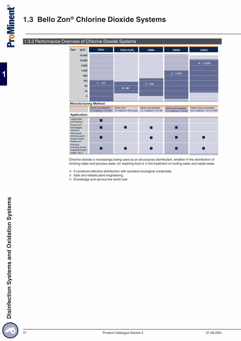
70
1.3.2 Performance Overview of Chlorine Dioxide SystemsCDLb H2SO4
8 – 89
H2SO4
8
3
Chlorine dioxide is increasingly being used as an all-purpose disinfectant, whether in the disinfection of drinking water and process water, for washing food or in the treatment of cooling water and waste water.
■ It combines effective disinfection with excellent ecological credentials ■ Safe and reliable plant engineering ■ Knowledge and service the world over
1.3 Bello Zon® Chlorine Dioxide Systems
01.06.2021Product Catalogue Volume 3
Dis
infe
ctio
n Sy
stem
s an
d O
xida
tion
Syst
ems
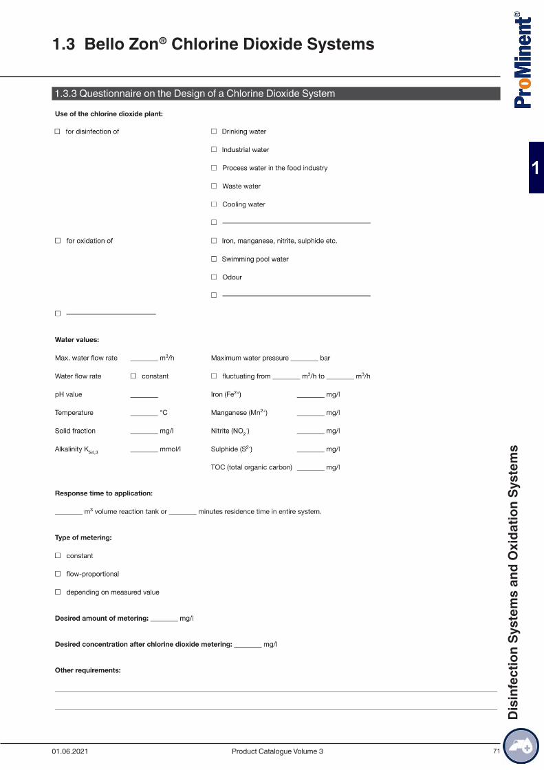
71
1.3.3 Questionnaire on the Design of a Chlorine Dioxide System
1.3 Bello Zon® Chlorine Dioxide Systems
01.06.2021 Product Catalogue Volume 3
Dis
infe
ctio
n Sy
stem
s an
d O
xida
tion
Syst
ems
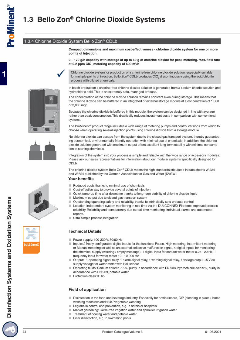
72
1.3.4 Chlorine Dioxide System Bello Zon® CDLbCompact dimensions and maximum cost-effectiveness - chlorine dioxide system for one or more points of injection.
0 – 120 g/h capacity with storage of up to 60 g of chlorine dioxide for peak metering. Max. flow rate at 0.2 ppm ClO2 metering capacity of 600 m3/h
9 Chlorine dioxide system for production of a chlorine-free chlorine dioxide solution, especially suitable for multiple points of injection. Bello Zon® CDLb produces ClO2 discontinuously using the acid/chlorite process with diluted chemicals.
In batch production a chlorine-free chlorine dioxide solution is generated from a sodium chlorite solution and hydrochloric acid. This is an extremely safe, managed process. The concentration of the chlorine dioxide solution remains constant even during storage. This means that the chlorine dioxide can be buffered in an integrated or external storage module at a concentration of 1,000 or 2,000 mg/l.
Because the chlorine dioxide is buffered in this module, the system can be designed in line with average rather than peak consumption. This drastically reduces investment costs in comparison with conventional systems.
The ProMinent® product range includes a wide range of metering pumps and control versions from which to choose when operating several injection points using chlorine dioxide from a storage module.
No chlorine dioxide can escape from the system due to the closed gas transport system, thereby guarantee-ing economical, environmentally friendly operation with minimal use of chemicals. In addition, the chlorine dioxide solution generated with maximum output offers excellent long-term stability with minimal consump-tion of starting chemicals.
Integration of the system into your process is simple and reliable with the wide range of accessory modules.Please ask our sales representatives for information about our modular systems specifically designed for CDLb.
The chlorine dioxide system Bello Zon® CDLb meets the high standards stipulated in data sheets W 224 and W 624 published by the German Association for Gas and Water (DVGW).Your benefits
■ Reduced costs thanks to minimal use of chemicals ■ Cost-effective way to provide several points of injection ■ Quick ramp-up time after downtime thanks to long-term stability of chlorine dioxide liquid ■ Maximum output due to closed gas transport system ■ Outstanding operating safety and reliability, thanks to intrinsically safe process control ■ Location-independent system monitoring in real time via the DULCONNEX Platform: Improved process
reliability. Reliability and transparency due to real-time monitoring, individual alarms and automated reports.
■ Ultra-simple process integration
Technical Details
■ Power supply: 100-230 V, 50/60 Hz ■ Inputs: 2 freely configurable digital inputs for the functions Pause, High metering, Intermittent metering
or Manual metering as well as an external collective malfunction signal, 4 digital inputs for monitoring the chemical supply (warning / empty message), 1 digital input for contact water meter 0.25 - 20 Hz, 1 frequency input for water meter 10 - 10,000 Hz
■ Outputs: 1 operating signal relay, 1 alarm signal relay, 1 warning signal relay, 1 voltage output +5 V as supply voltage for water meter with Hall sensor
■ Operating fluids: Sodium chlorite 7.5%, purity in accordance with EN 938, hydrochloric acid 9%, purity in accordance with EN 939, potable water
■ Protection class: IP 65
Field of application
■ Disinfection in the food and beverage industry. Especially for bottle rinsers, CIP (cleaning in place), bottle washing machines and fruit / vegetable washing
■ Legionella control and prevention, e.g. in hotels or hospitals ■ Market gardening: Germ-free irrigation water and sprinkler irrigation water ■ Treatment of cooling water and potable water ■ Filter disinfection, e.g. in swimming pools
1.3 Bello Zon® Chlorine Dioxide Systems
01.06.2021Product Catalogue Volume 3
Dis
infe
ctio
n Sy
stem
s an
d O
xida
tion
Syst
ems
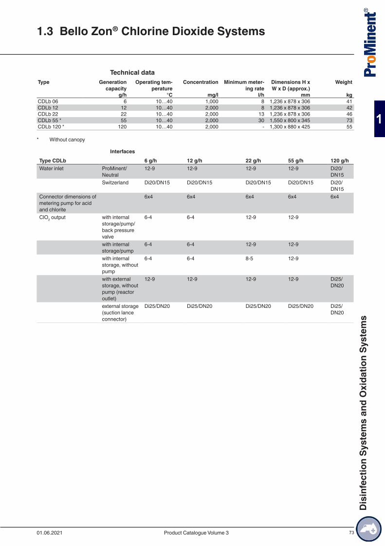
73
Technical data
Type Generation capacity
Operating tem-perature
Concentration Minimum meter-ing rate
Dimensions H x W x D (approx.)
Weight
g/h °C mg/l l/h mm kgCDLb 06 6 10…40 1,000 8 1,236 x 878 x 306 41CDLb 12 12 10…40 2,000 8 1,236 x 878 x 306 42CDLb 22 22 10…40 2,000 13 1,236 x 878 x 306 46CDLb 55 * 55 10…40 2,000 30 1,550 x 800 x 345 73CDLb 120 * 120 10…40 2,000 - 1,300 x 880 x 425 55
* Without canopy
InterfacesType CDLb 6 g/h 12 g/h 22 g/h 55 g/h 120 g/hWater inlet ProMinent/
Neutral12-9 12-9 12-9 12-9 Di20/
DN15 Switzerland Di20/DN15 Di20/DN15 Di20/DN15 Di20/DN15 Di20/
DN15Connector dimensions of metering pump for acid and chlorite
6x4 6x4 6x4 6x4 6x4
ClO2 output with internal storage/pump/back pressure valve
6-4 6-4 12-9 12-9
with internal storage/pump
6-4 6-4 12-9 12-9
with internal storage, without pump
6-4 6-4 8-5 12-9
with external storage, without pump (reactor outlet)
12-9 12-9 12-9 12-9 Di25/DN20
external storage (suction lance connector)
Di25/DN20 Di25/DN20 Di25/DN20 Di25/DN20 Di25/DN20
1.3 Bello Zon® Chlorine Dioxide Systems
01.06.2021 Product Catalogue Volume 3
Dis
infe
ctio
n Sy
stem
s an
d O
xida
tion
Syst
ems
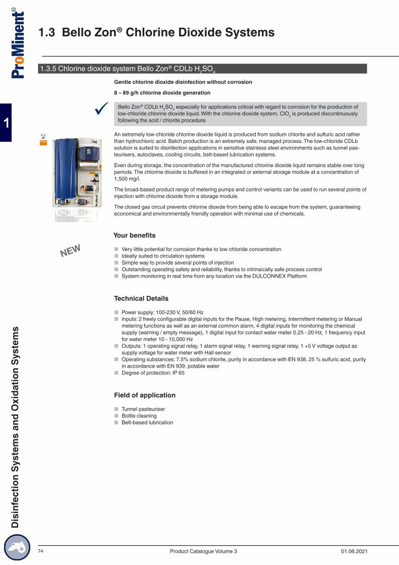
74
1.3.5 Chlorine dioxide system Bello Zon® CDLb H2SO4
Gentle chlorine dioxide disinfection without corrosion
8 – 89 g/h chlorine dioxide generation
9 Bello Zon® CDLb H2SO4 especially for applications critical with regard to corrosion for the production of low-chloride chlorine dioxide liquid. With the chlorine dioxide system, ClO2 is produced discontinuously following the acid / chlorite procedure.
An extremely low-chloride chlorine dioxide liquid is produced from sodium chlorite and sulfuric acid rather than hydrochloric acid. Batch production is an extremely safe, managed process. The low-chloride CDLb solution is suited to disinfection applications in sensitive stainless steel environments such as tunnel pas-teurisers, autoclaves, cooling circuits, belt-based lubrication systems.
Even during storage, the concentration of the manufactured chlorine dioxide liquid remains stable over long periods. The chlorine dioxide is buffered in an integrated or external storage module at a concentration of 1,500 mg/l.
The broad-based product range of metering pumps and control variants can be used to run several points of injection with chlorine dioxide from a storage module.
The closed gas circuit prevents chlorine dioxide from being able to escape from the system, guaranteeing economical and environmentally friendly operation with minimal use of chemicals.
Your benefits
■ Very little potential for corrosion thanks to low chloride concentration ■ Ideally suited to circulation systems ■ Simple way to provide several points of injection ■ Outstanding operating safety and reliability, thanks to intrinsically safe process control ■ System monitoring in real time from any location via the DULCONNEX Platform
Technical Details
■ Power supply: 100-230 V, 50/60 Hz ■ Inputs: 2 freely configurable digital inputs for the Pause, High metering, Intermittent metering or Manual
metering functions as well as an external common alarm, 4 digital inputs for monitoring the chemical supply (warning / empty message), 1 digital input for contact water meter 0.25 - 20 Hz, 1 frequency input for water meter 10 - 10,000 Hz
■ Outputs: 1 operating signal relay, 1 alarm signal relay, 1 warning signal relay, 1 +5 V voltage output as supply voltage for water meter with Hall sensor
■ Operating substances: 7.5% sodium chlorite, purity in accordance with EN 938, 25 % sulfuric acid, purity in accordance with EN 939, potable water
■ Degree of protection: IP 65
Field of application
■ Tunnel pasteuriser ■ Bottle cleaning ■ Belt-based lubrication
1.3 Bello Zon® Chlorine Dioxide Systems
01.06.2021Product Catalogue Volume 3
Dis
infe
ctio
n Sy
stem
s an
d O
xida
tion
Syst
ems
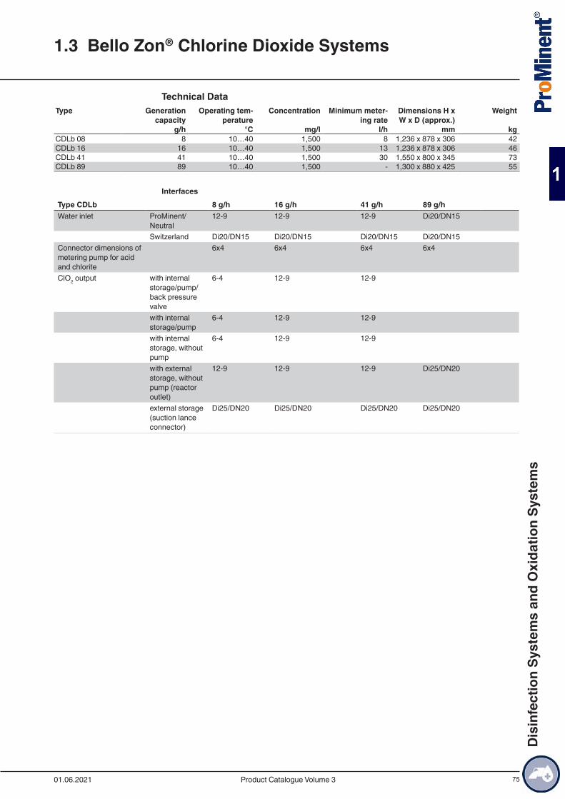
75
Technical DataType Generation
capacityOperating tem-
peratureConcentration Minimum meter-
ing rateDimensions H x W x D (approx.)
Weight
g/h °C mg/l l/h mm kgCDLb 08 8 10…40 1,500 8 1,236 x 878 x 306 42CDLb 16 16 10…40 1,500 13 1,236 x 878 x 306 46CDLb 41 41 10…40 1,500 30 1,550 x 800 x 345 73CDLb 89 89 10…40 1,500 - 1,300 x 880 x 425 55
InterfacesType CDLb 8 g/h 16 g/h 41 g/h 89 g/h Water inlet ProMinent/
Neutral12-9 12-9 12-9 Di20/DN15
Switzerland Di20/DN15 Di20/DN15 Di20/DN15 Di20/DN15 Connector dimensions of metering pump for acid and chlorite
6x4 6x4 6x4 6x4
ClO2 output with internal storage/pump/back pressure valve
6-4 12-9 12-9
with internal storage/pump
6-4 12-9 12-9
with internal storage, without pump
6-4 12-9 12-9
with external storage, without pump (reactor outlet)
12-9 12-9 12-9 Di25/DN20
external storage (suction lance connector)
Di25/DN20 Di25/DN20 Di25/DN20 Di25/DN20
1.3 Bello Zon® Chlorine Dioxide Systems
01.06.2021 Product Catalogue Volume 3
Dis
infe
ctio
n Sy
stem
s an
d O
xida
tion
Syst
ems
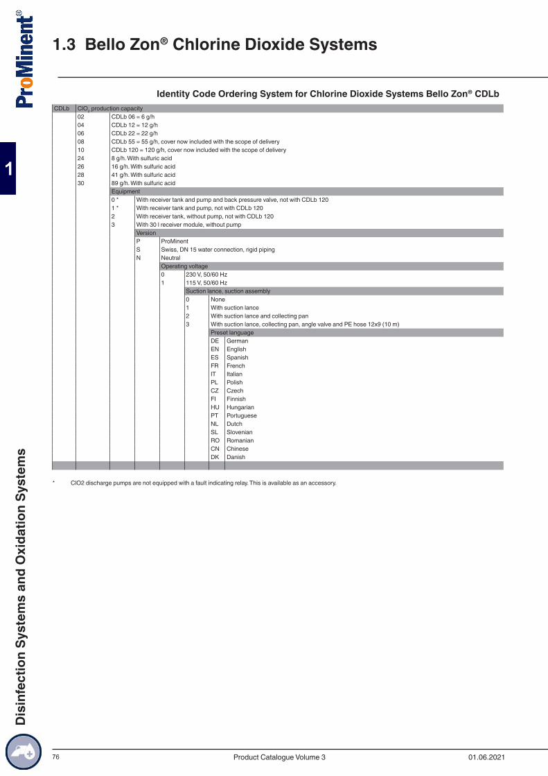
76
Identity Code Ordering System for Chlorine Dioxide Systems Bello Zon® CDLb CDLb ClO2 production capacity
02 CDLb 06 = 6 g/h04 CDLb 12 = 12 g/h06 CDLb 22 = 22 g/h08 CDLb 55 = 55 g/h, cover now included with the scope of delivery10 CDLb 120 = 120 g/h, cover now included with the scope of delivery24 8 g/h. With sulfuric acid26 16 g/h. With sulfuric acid28 41 g/h. With sulfuric acid30 89 g/h. With sulfuric acid
Equipment0 * With receiver tank and pump and back pressure valve, not with CDLb 1201 * With receiver tank and pump, not with CDLb 1202 With receiver tank, without pump, not with CDLb 1203 With 30 l receiver module, without pump
VersionP ProMinentS Swiss, DN 15 water connection, rigid pipingN Neutral
Operating voltage0 230 V, 50/60 Hz1 115 V, 50/60 Hz
Suction lance, suction assembly0 None1 With suction lance2 With suction lance and collecting pan3 With suction lance, collecting pan, angle valve and PE hose 12x9 (10 m)
Preset languageDE GermanEN EnglishES SpanishFR FrenchIT ItalianPL PolishCZ CzechFI FinnishHU HungarianPT PortugueseNL DutchSL SlovenianRO RomanianCN ChineseDK Danish
* ClO2 discharge pumps are not equipped with a fault indicating relay. This is available as an accessory.
1.3 Bello Zon® Chlorine Dioxide Systems
01.06.2021Product Catalogue Volume 3
Dis
infe
ctio
n Sy
stem
s an
d O
xida
tion
Syst
ems
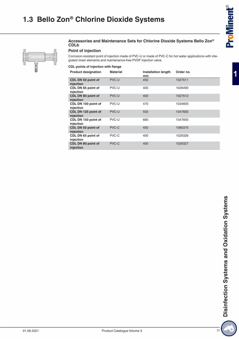
77
Accessories and Maintenance Sets for Chlorine Dioxide Systems Bello Zon® CDLb Point of injectionCorrosion-resistant point of injection made of PVC-U or made of PVC-C for hot water applications with inte-grated mixer elements and maintenance-free PVDF injection valve.
CDL points of injection with flangeProduct designation Material Installation length Order no. mm CDL DN 50 point of injection
PVC-U 450 1027611
CDL DN 65 point of injection
PVC-U 400 1026490
CDL DN 80 point of injection
PVC-U 400 1027612
CDL DN 100 point of injection
PVC-U 470 1034693
CDL DN 125 point of injection
PVC-U 550 1047692
CDL DN 150 point of injection
PVC-U 680 1047693
CDL DN 50 point of injection
PVC-C 450 1080375
CDL DN 65 point of injection
PVC-C 400 1029326
CDL DN 80 point of injection
PVC-C 400 1029327
1.3 Bello Zon® Chlorine Dioxide Systems
01.06.2021 Product Catalogue Volume 3
Dis
infe
ctio
n Sy
stem
s an
d O
xida
tion
Syst
ems
78
CDL points of injection with threaded connector (including separate reductions in each case to one nominal width smaller)Product designation Material Order no.CDL DN 25 point of injection PVC-C 1080362CDL DN 40 point of injection PVC-C 1080374CDL DN 25 point of injection PVC-U 1080359CDL DN 40 point of injection PVC-U 1080361
Temperature/pressure resistance of point of injection CDLWater temperature (°C) Maximum permissible operating pressure (bar) PVC-U PVC-C40 12 1250 7 9.560 4.5 7.570 – 580 – 3
Back pressure valve and angle valveBack pressure valve type DHV with wall bracket and 6 x 4 mm hose connection for fitting in the chlorine di-oxide dosing line. Angle valve for the transition from the customer’s process water pipeline to the 12x9 hose connector on the CDLb.
Order no.DHV-S-DK 1.0 - 10 bar d6-12 PC1 302321Angle valve kit (support insert 12/9 stainless steel) DN15 G 1/2” brass
1046350
Fault indicating relay for the ClO2 pumpFault indicating relay retrofit kit for the ClO2 discharge pump
Order no.Relay 3-pin 1029309
Hood for CDLbOrder no.
Hood for CDLb 55 PE black 1045889Hood for CDLb 120 PE black 1045890
Safety collecting pan for chemical containersCollecting pan with two separate compartments - 1 No. 25 l Bello Zon® acid and 1 No. 10 l Bello Zon® chlo-rite chemical container.
Dimensions (HxWxD): 290 x 700 x 350 mmOrder no.
Safety collecting pan CDLa 1026744
Safety collecting pan for chemical tanks (CDLb)Collecting pan for a 25 l Bello Zon® acid or Bello Zon® chlorite chemical canister.
Dimensions (HxWxD): 266 x 400 x 500 mmOrder no.
Safety collecting pan CDLb 791726
1.3 Bello Zon® Chlorine Dioxide Systems
01.06.2021Product Catalogue Volume 3
Dis
infe
ctio
n Sy
stem
s an
d O
xida
tion
Syst
ems
79
Maintenance kits for CDLaThe kits contain all wear parts that have to be replaced within the scope of regular system maintenance. This is the annual kit and every 3 years, the 3-yearly kit also has to be used.
Order no.1-year maintenance kit for pressure relief valve 1029442
For CDLa with ClO2 pumpType Order no.
Annual maintenance kit, 230 V CDL 5 10272633-yearly maintenance set, 230 V CDL 5 1049659Annual maintenance kit, 230 V CDL 10 10315493-yearly maintenance set, 230 V CDL 10 1049665Annual maintenance kit, 115 V CDLa 5 10801083-yearly maintenance set, 115 V CDLa 5 1049657Annual maintenance kit, 115 V CDLa 10 10801103-yearly maintenance set, 115 V CDLa 10 1049663
For CDLa without ClO2 pumpType Order no.
Annual maintenance kit, 230 V CDL5 10428293-yearly maintenance set, 230 V CDL5 1049660Annual maintenance kit, 230 V CDL10 10428303-yearly maintenance set, 230 V CDL10 1049666Annual maintenance kit, 115 V CDLa 5 10801073-yearly maintenance set, 115 V CDLa 5 1049658Annual maintenance kit, 115 V CDLa 10 10801093-yearly maintenance set, 115 V CDLa 10 1049664
Maintenance kits for Bello Zon® CDLb
For CDLb with storage tank, pump and back pressure valveType Order no.
Annual maintenance kit, 230 V CDLb 06, CDLb 12, CDLb 08 H2SO4
1044484
Annual maintenance kit, 230 V CDLb 22, CDLb 16 H2SO4 1044501Annual maintenance kit, 230 V CDLb 55, CDLb 41 H2SO4 1044509Annual maintenance kit, 115 V CDLb 06, CDLb 12, CDLb 08
H2SO4
1079198
Annual maintenance kit, 115 V CDLb 22, CDLb 16 H2SO4 1079202Annual maintenance kit, 115 V CDLb 55, CDLb 41 H2SO4 10792063-yearly maintenance set, 230 V CDLb 06, CDLb 12, CDLb 08
H2SO4
1044494
3-yearly maintenance set, 230 V CDLb 22, CDLb 16 H2SO4 10445023-yearly maintenance set, 230 V CDLb 55, CDLb 41 H2SO4 10445103-yearly maintenance set, 115 V CDLb 06, CDLb 12, CDLb 08
H2SO4
1045212
3-yearly maintenance set, 115 V CDLb 22, CDLb 16 H2SO4 10452163-yearly maintenance set, 115 V CDLb 55, CDLb 41 H2SO4 1045220
1.3 Bello Zon® Chlorine Dioxide Systems
01.06.2021 Product Catalogue Volume 3
Dis
infe
ctio
n Sy
stem
s an
d O
xida
tion
Syst
ems
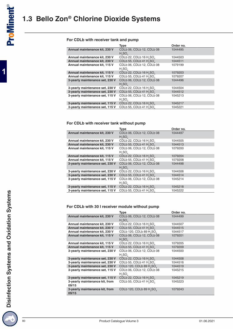
80
For CDLb with receiver tank and pumpType Order no.
Annual maintenance kit, 230 V CDLb 06, CDLb 12, CDLb 08 H2SO4
1044495
Annual maintenance kit, 230 V CDLb 22, CDLb 16 H2SO4 1044503Annual maintenance kit, 230 V CDLb 55, CDLb 41 H2SO4 1044511Annual maintenance kit, 115 V CDLb 06, CDLb 12, CDLb 08
H2SO4
1079199
Annual maintenance kit, 115 V CDLb 22, CDLb 16 H2SO4 1079203Annual maintenance kit, 115 V CDLb 55, CDLb 41 H2SO4 10792073-yearly maintenance set, 230 V CDLb 06, CDLb 12, CDLb 08
H2SO4
1044496
3-yearly maintenance set, 230 V CDLb 22, CDLb 16 H2SO4 10445043-yearly maintenance set, 230 V CDLb 55, CDLb 41 H2SO4 10445123-yearly maintenance set, 115 V CDLb 06, CDLb 12, CDLb 08
H2SO4
1045213
3-yearly maintenance set, 115 V CDLb 22, CDLb 16 H2SO4 10452173-yearly maintenance set, 115 V CDLb 55, CDLb 41 H2SO4 1045221
For CDLb with receiver tank without pumpType Order no.
Annual maintenance kit, 230 V CDLb 06, CDLb 12, CDLb 08 H2SO4
1044497
Annual maintenance kit, 230 V CDLb 22, CDLb 16 H2SO4 1044505Annual maintenance kit, 230 V CDLb 55, CDLb 41 H2SO4 1044513Annual maintenance kit, 115 V CDLb 06, CDLb 12, CDLb 08
H2SO4
1079200
Annual maintenance kit, 115 V CDLb 22, CDLb 16 H2SO4 1079204Annual maintenance kit, 115 V CDLb 55, CDLb 41 H2SO4 10792083-yearly maintenance set, 230 V CDLb 06, CDLb 12, CDLb 08
H2SO4
1044498
3-yearly maintenance set, 230 V CDLb 22, CDLb 16 H2SO4 10445063-yearly maintenance set, 230 V CDLb 55, CDLb 41 H2SO4 10445143-yearly maintenance set, 115 V CDLb 06, CDLb 12, CDLb 08
H2SO4
1045214
3-yearly maintenance set, 115 V CDLb 22, CDLb 16 H2SO4 10452183-yearly maintenance set, 115 V CDLb 55, CDLb 41 H2SO4 1045222
For CDLb with 30 l receiver module without pumpType Order no.
Annual maintenance kit, 230 V CDLb 06, CDLb 12, CDLb 08 H2SO4
1044499
Annual maintenance kit, 230 V CDLb 22, CDLb 16 H2SO4 1044507Annual maintenance kit, 230 V CDLb 55, CDLb 41 H2SO4 1044515Annual maintenance kit, 230 V CDLb 120, CDLb 89 H2SO4 1044517Annual maintenance kit, 115 V CDLb 06, CDLb 12, CDLb 08
H2SO4
1079201
Annual maintenance kit, 115 V CDLb 22, CDLb 16 H2SO4 1079205Annual maintenance kit, 115 V CDLb 55, CDLb 41 H2SO4 10792093-yearly maintenance set, 230 V CDLb 06, CDLb 12, CDLb 08
H2SO4
1044500
3-yearly maintenance set, 230 V CDLb 22, CDLb 16 H2SO4 10445083-yearly maintenance set, 230 V CDLb 55, CDLb 41 H2SO4 10445163-yearly maintenance set, 230 V CDLb 120, CDLb 89 H2SO4 10445193-yearly maintenance set, 115 V CDLb 06, CDLb 12, CDLb 08
H2SO4
1045215
3-yearly maintenance set, 115 V CDLb 22, CDLb 16 H2SO4 10452193-yearly maintenance kit, from 09/15
CDLb 55, CDLb 41 H2SO4 1045223
3-yearly maintenance kit, from 09/15
CDLb 120, CDLb 89 H2SO4 1079243
1.3 Bello Zon® Chlorine Dioxide Systems
01.06.2021Product Catalogue Volume 3
Dis
infe
ctio
n Sy
stem
s an
d O
xida
tion
Syst
ems
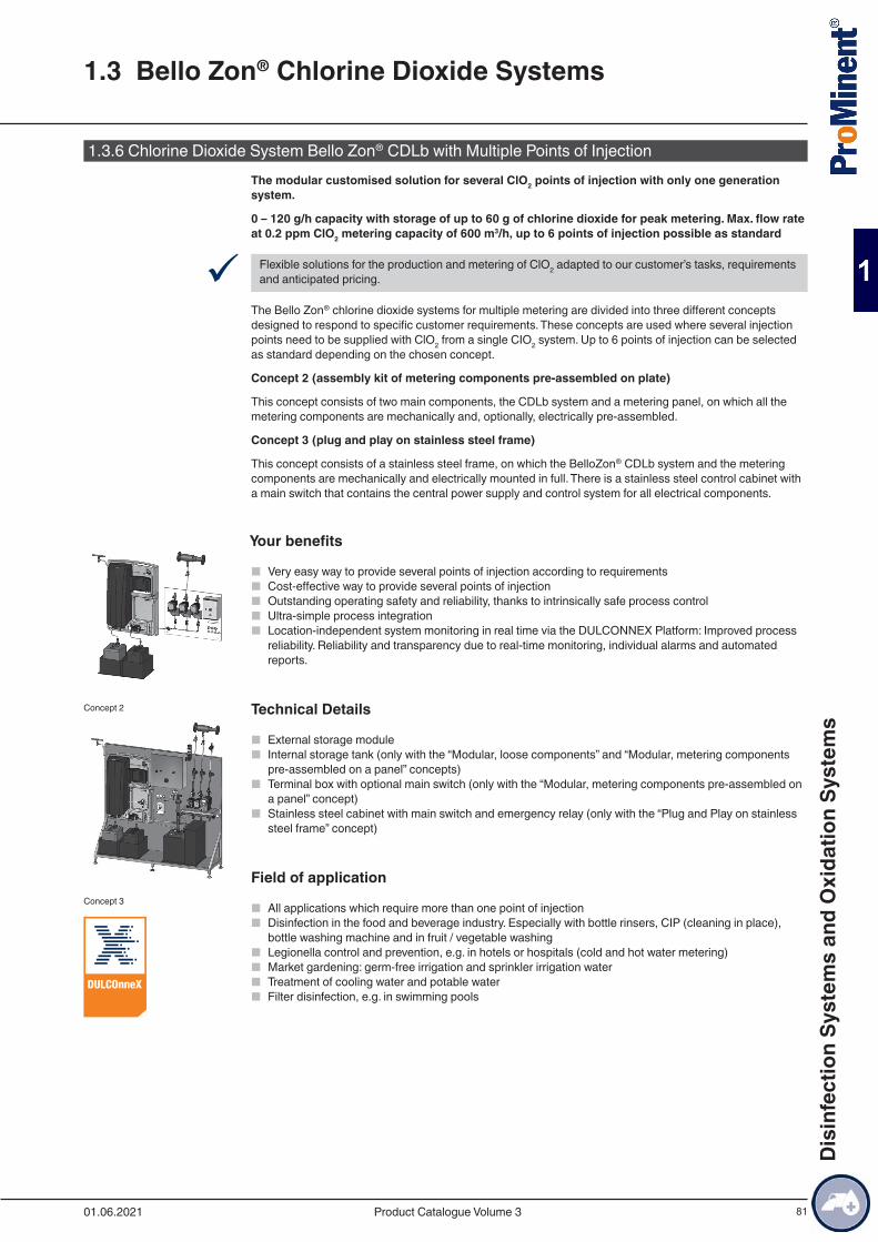
81
1.3.6 Chlorine Dioxide System Bello Zon® CDLb with Multiple Points of InjectionThe modular customised solution for several ClO2 points of injection with only one generation system.
0 – 120 g/h capacity with storage of up to 60 g of chlorine dioxide for peak metering. Max. flow rate at 0.2 ppm ClO2 metering capacity of 600 m3/h, up to 6 points of injection possible as standard
9 Flexible solutions for the production and metering of ClO2 adapted to our customer’s tasks, requirements and anticipated pricing.
The Bello Zon® chlorine dioxide systems for multiple metering are divided into three different concepts designed to respond to specific customer requirements. These concepts are used where several injection points need to be supplied with ClO2 from a single CIO2 system. Up to 6 points of injection can be selected as standard depending on the chosen concept.
Concept 2 (assembly kit of metering components pre-assembled on plate)
This concept consists of two main components, the CDLb system and a metering panel, on which all the metering components are mechanically and, optionally, electrically pre-assembled.
Concept 3 (plug and play on stainless steel frame)
This concept consists of a stainless steel frame, on which the BelloZon® CDLb system and the metering components are mechanically and electrically mounted in full. There is a stainless steel control cabinet with a main switch that contains the central power supply and control system for all electrical components.
Your benefits
■ Very easy way to provide several points of injection according to requirements ■ Cost-effective way to provide several points of injection ■ Outstanding operating safety and reliability, thanks to intrinsically safe process control ■ Ultra-simple process integration ■ Location-independent system monitoring in real time via the DULCONNEX Platform: Improved process
reliability. Reliability and transparency due to real-time monitoring, individual alarms and automated reports.
Technical Details
■ External storage module ■ Internal storage tank (only with the “Modular, loose components” and “Modular, metering components
pre-assembled on a panel” concepts) ■ Terminal box with optional main switch (only with the “Modular, metering components pre-assembled on
a panel” concept) ■ Stainless steel cabinet with main switch and emergency relay (only with the “Plug and Play on stainless
steel frame” concept)
Field of application
■ All applications which require more than one point of injection ■ Disinfection in the food and beverage industry. Especially with bottle rinsers, CIP (cleaning in place),
bottle washing machine and in fruit / vegetable washing ■ Legionella control and prevention, e.g. in hotels or hospitals (cold and hot water metering) ■ Market gardening: germ-free irrigation and sprinkler irrigation water ■ Treatment of cooling water and potable water ■ Filter disinfection, e.g. in swimming pools
Concept 2
Concept 3
1.3 Bello Zon® Chlorine Dioxide Systems
01.06.2021 Product Catalogue Volume 3
Dis
infe
ctio
n Sy
stem
s an
d O
xida
tion
Syst
ems
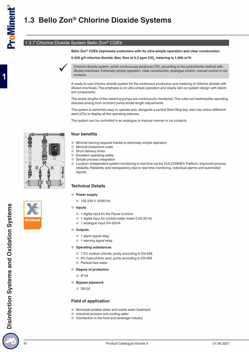
82
1.3.7 Chlorine Dioxide System Bello Zon® CDEbBello Zon® CDEb impresses customers with its ultra-simple operation and clear construction.
5-200 g/h chlorine dioxide. Max. flow at 0.2 ppm ClO2 metering is 1,000 m3/h
9 Chlorine dioxide system, which continuously produces ClO2 according to the acid/chlorite method with diluted chemicals. Extremely simple operation, clear construction, analogue control, manual control or via contacts.
A ready-to-use chlorine dioxide system for the continuous production and metering of chlorine dioxide with diluted chemicals. The emphasis is on ultra-simple operation and clearly laid out system design with stand-ard components.
The stroke lengths of the metering pumps are continuously monitored. This rules out inadmissible operating statuses arising from incorrect pump stroke length adjustments.
The system is extremely easy to operate and, alongside a central Start-Stop key, also has colour-differenti-ated LEDs to display all the operating statuses.
The system can be controlled in an analogue or manual manner or via contacts
Your benefits
■ Minimal training required thanks to extremely simple operation ■ Minimal investment costs ■ Short delivery times ■ Excellent operating safety ■ Simple process integration ■ Location-independent system monitoring in real time via the DULCONNEX Platform: Improved process
reliability. Reliability and transparency due to real-time monitoring, individual alarms and automated reports.
Technical Details
■ Power supply
■ 100-230 V, 50/60 Hz
■ Inputs
■ 1 digital input for the Pause function ■ 1 digital input for contact water meter 0.25-20 Hz ■ 1 analogue input 0/4-20mA
■ Outputs
■ 1 alarm signal relay ■ 1 warning signal relay
■ Operating substances
■ 7.5% sodium chlorite, purity according to EN 938 ■ 9% hydrochloric acid, purity according to EN 939 ■ Particle-free water
■ Degree of protection
■ IP 54
■ Bypass pipework
■ DN 20
Field of application
■ Municipal potable water and waste water treatment ■ Industrial process and cooling water ■ Disinfection in the food and beverage industry
1.3 Bello Zon® Chlorine Dioxide Systems
01.06.2021Product Catalogue Volume 3
Dis
infe
ctio
n Sy
stem
s an
d O
xida
tion
Syst
ems
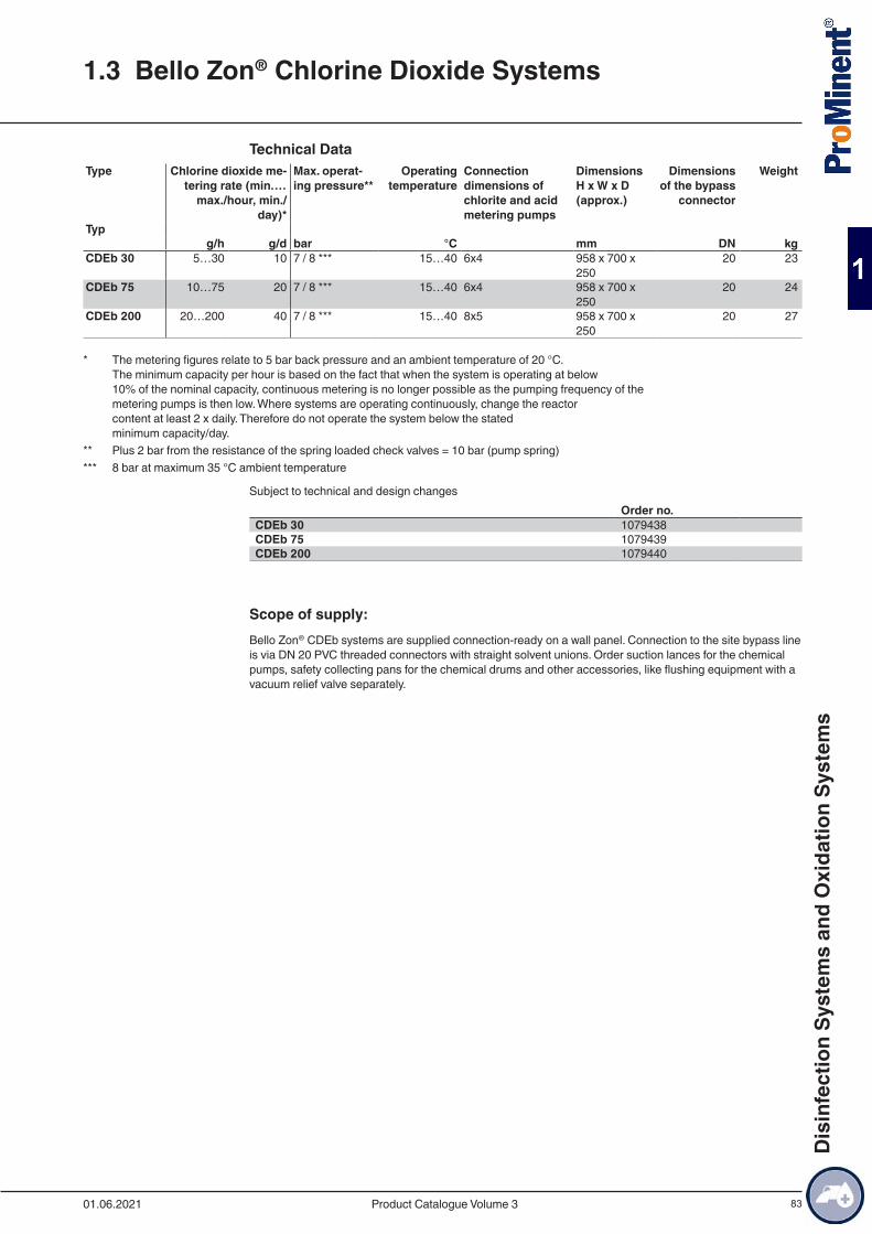
83
Technical DataType Chlorine dioxide me-
tering rate (min.…max./hour, min./
day)*
Max. operat-ing pressure**
Operating temperature
Connection dimensions of chlorite and acid metering pumps
Dimensions H x W x D (approx.)
Dimensions of the bypass
connector
Weight
Typ g/h g/d bar °C mm DN kgCDEb 30 5…30 10 7 / 8 *** 15…40 6x4 958 x 700 x
25020 23
CDEb 75 10…75 20 7 / 8 *** 15…40 6x4 958 x 700 x 250
20 24
CDEb 200 20…200 40 7 / 8 *** 15…40 8x5 958 x 700 x 250
20 27
* The metering figures relate to 5 bar back pressure and an ambient temperature of 20 °C. The minimum capacity per hour is based on the fact that when the system is operating at below 10% of the nominal capacity, continuous metering is no longer possible as the pumping frequency of the metering pumps is then low. Where systems are operating continuously, change the reactor content at least 2 x daily. Therefore do not operate the system below the stated minimum capacity/day.
** Plus 2 bar from the resistance of the spring loaded check valves = 10 bar (pump spring)*** 8 bar at maximum 35 °C ambient temperature
Subject to technical and design changesOrder no.
CDEb 30 1079438CDEb 75 1079439CDEb 200 1079440
Scope of supply:Bello Zon® CDEb systems are supplied connection-ready on a wall panel. Connection to the site bypass line is via DN 20 PVC threaded connectors with straight solvent unions. Order suction lances for the chemical pumps, safety collecting pans for the chemical drums and other accessories, like flushing equipment with a vacuum relief valve separately.
1.3 Bello Zon® Chlorine Dioxide Systems
01.06.2021 Product Catalogue Volume 3
Dis
infe
ctio
n Sy
stem
s an
d O
xida
tion
Syst
ems
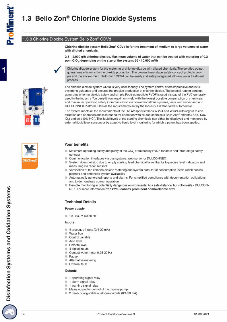
84
1.3.8 Chlorine Dioxide System Bello Zon® CDVdChlorine dioxide system Bello Zon® CDVd is for the treatment of medium to large volumes of water with diluted chemicals.
2.5 – 2,000 g/h chlorine dioxide. Maximum volume of water that can be treated with metering of 0.2 ppm ClO2, depending on the size of the system: 50 - 10,000 m3/h
9 Chlorine dioxide system for the metering of chlorine dioxide with diluted chemicals. The certified output guarantees efficient chlorine dioxide production. The proven three-stage safety concept protects peo-ple and the environment. Bello Zon® CDVd can be easily and safely integrated into any water treatment process.
The chlorine dioxide system CDVd is very user-friendly. The system control offers impressive and intui-tive menu guidance and ensures the precise production of chlorine dioxide. The special reactor concept generates chlorine dioxide safely and simply. Food-compatible PVDF is used instead of the PVC generally used in the industry. You benefit from maximum yield with the lowest possible consumption of chemicals and maximum operating safety. Communication via conventional bus systems, via a web server and our DULCONNEX Platform fulfils all the requirements set by the Industry 4.0 standards of tomorrow.The system meets all the requirements of the DVGW specifications W 224 and W 624 with regard to con-struction and operation and is intended for operation with diluted chemicals Bello Zon® chlorite (7.5% NaC-lO2) and acid (9% HCl). The liquid levels of the starting chemicals can either be displayed and monitored by external liquid level sensors or by adaptive liquid level monitoring for which a patent has been applied.
Your benefits ■ Maximum operating safety and purity of the CIO2 produced by PVDF reactors and three-stage safety
concept ■ Communication interfaces via bus systems, web server or DULCONNEX ■ System does not stop due to empty starting feed chemical tanks thanks to precise level indicators and
measuring via radar sensors ■ Verification of the chlorine dioxide metering and system output: For consumption levels which can be
planned and enhanced system availability ■ Automatically generated reports and alarms: For simplified compliance with documentation obligations
and to demonstrate correct operation ■ Remote monitoring in potentially dangerous environments: At a safe distance, but still on-site - DULCON-
NEX. For more information:https://dulconnex.prominent.com/welcome.html
Technical DetailsPower supply
■ 100-230 V, 50/60 Hz
Inputs
■ 4 analogue inputs (0/4-20 mA) ■ Water flow ■ Control variable ■ Acid level ■ Chlorite level ■ 4 digital inputs ■ Contact water meter 0.25-20 Hz ■ Pause ■ Alternative metering ■ External fault
Outputs
■ 1 operating signal relay ■ 1 alarm signal relay ■ 1 warning signal relay ■ Mains output for control of the bypass pump ■ 2 freely configurable analogue outputs (0/4-20 mA)
1.3 Bello Zon® Chlorine Dioxide Systems
01.06.2021Product Catalogue Volume 3
Dis
infe
ctio
n Sy
stem
s an
d O
xida
tion
Syst
ems
85
Operating substances
■ 7.5% sodium chlorite, purity according to EN 938 ■ 9% hydrochloric acid, purity according to EN 939 ■ Particle-free water
Degree of protection
■ IP 65
Bus communication options
■ Modbus TCP / DULCONNEX ■ Modbus RTU / DULCONNEX ■ Profibus DULCONNEX ■ Profinet DULCONNEX
Field of application
■ Municipal drinking water and waste water treatment ■ Industrial process and cooling water ■ Disinfection in the food and beverage industry, above all with inlet water treatment
Technical DataType Chlorine dioxide metering rate
(min.…max./hour, min./day)*Max. operat-
ing pressure**Operating tem-
peratureAcid Dimensions
of the bypass connector
g/h g/d bar °C DNCDVd 45 2.5…45 16 8 10…40 6x4 6x4 25CDVd 120 6…120 40 8 10…40 6x4 6x4 25CDVd 240 12…240 80 8 10…40 8x5 8x5 25CDVd 600 30…600 140 8 15…40 12x9 12x9 25CDVd 2000 100…2,000 468 5 15…40 Pressure hose
nozzle d16Pressure hose nozzle d16
40
* The metering figures relate to 5 or 2 bar back pressure and an ambient temperature of 20 °C. The minimum capacity per hour is based on the fact that when the system is operating at below 5 % of the nominal capacity, continuous metering is no longer possible as the pumping frequency of the metering pumps is then low. When plants are not operating continuously, the reactor contents should be changed at least twice a day. Therefore do not operate the system below the stated minimum capacity/day.
** at an ambient temperature of 35 °C
Type Dimensions H x W x D (approx.)*
Weight Supply voltage 230 V**
Supply voltage 115 V**
Power con-sumption
without by-pass pump
Power con-sumption
with bypass pump
HCl*** NaClO2
mm kg A A W W l/h l/hCDVd 45 1,300 x 1,000 x 250 55 3.8 1.6 100 630 1.1 1.1CDVd 120 1,300 x 1,000 x 250 55 3.9 1.6 110 640 2.9 2.9CDVd 240 1,300 x 1,000 x 250 59 3.9 1.8 120 650 5.7 5.7CDVd 600 1,525 x 1,160 x 253 84 4.0 1.9 220 750 14.3 14.3CDVd 2000 2,000 x 1,320 x 290 129 - 2.6 300 - 47.6 47.6
* including main system, pre-dilution and rinse valve, without bypass pump and water feed section** 230 V figures with bypass pump (CDKd 150-900), 115 V figures without bypass pump*** Sodium chlorite (NaClO2) 24.5 %, purity in accordance with EN 938, hydrochloric acid 25-36%, purity in accordance with EN 939. The
chemical consumption may vary depending on the temperature. The hydrochloric acid consumption is calculated for a concentration of 30%. Up to 25% hydrochloric acid can be saved with the aid of automatic acid adjustment.
1.3 Bello Zon® Chlorine Dioxide Systems
01.06.2021 Product Catalogue Volume 3
Dis
infe
ctio
n Sy
stem
s an
d O
xida
tion
Syst
ems

86
Ambient conditions:Permissible relative air humidity (non-condensing) max. 85% rel.Permissible ambient temperature 40 °CPermissible temperature of chemicals 10 … 35 °CStorage and transport temperature -10 … +40 °CDegree of protection IP 65
1.3 Bello Zon® Chlorine Dioxide Systems
01.06.2021Product Catalogue Volume 3
Dis
infe
ctio
n Sy
stem
s an
d O
xida
tion
Syst
ems

87
Identity code ordering system for CDVd systemsCDVd Capacity
45 CDVd 00045 = 45 g/h120 CDVd 00120 = 120 g/h240 CDVd 00240 = 240 g/h600 CDVd 00600 = 600 g/h2000 CDVd 02000 = 2,000 g/h
VersionP ProMinent
Bypass version0 without bypass1 Bypass PVC-U without bypass pump2 Bypass PVC-U with bypass pump 230 V / 50 Hz3 Bypass in USA design with ASI connections and unit in gpm, without bypass pump (only up to 600 g/h)4 Bypass for the secure filling of a buffer tank with 24 V valve and water meter, without buffer tank / without bypass pump
(CDVd 240 + 600)5 Bypass 24 V for the secure filling of a buffer tank with 24 V valve and water meter, with 30-litre buffer tank, without bypass
pump (CDVd 120 - 600 g/h)6 Bypass for the secure filling of a buffer tank with 24 V valve and water meter, with 150 litre buffer tank, without bypass
pump (CDVd 120 - 2,000 g/h)Suction lance, suction assembly for chemicals0 None1 Suction lance for 5 ... 60 l storage tank2 Suction lance for 200 l storage tank3 Flexible suction assembly up to 5 m with two-stage level switch4 Suction lance for 25 l storage tank with two 40 l collecting pans without leak sensor
Preset languageDE GermanEN EnglishFR FrenchIT ItalianES SpanishSV SwedishFI FinnishBG BulgarianCN ChineseDA DanishEL GreekET EstonianHR CroatianHU HungarianLT LithuanianLV LatvianMS MalayNL DutchNO NorwegianPL PolishPT PortugueseRO RomanianRU RussianSK SlovakianSL SlovenianTR TurkishCZ Czech
Analogue input / output0 none1 with input / output2 with input / output and with level measurement for chlorite + acid via radar sensors
Bus communication0 none1 Modbus TCP2 Modbus RTU3 PROFIBUS® DP4 PROFINET5 Modbus TCP / DULCOnneX6 Modbus RTU / DULCOnneX7 PROFIBUS® / DULCOnneX8 PROFINET / DULCOnneX
1.3 Bello Zon® Chlorine Dioxide Systems
01.06.2021 Product Catalogue Volume 3
Dis
infe
ctio
n Sy
stem
s an
d O
xida
tion
Syst
ems

88
Maintenance Sets for Bello Zon® CDV Chlorine Dioxide SystemsThe maintenance kits contain all wear parts that have to be replaced within the scope of regular system maintenance.
Maintenance kits for CDVd plantsOrder no.
Maintenance kit, complete CDVd 45 1105948Maintenance kit, complete CDVd 120 1105949Maintenance kit, complete CDVd 240 1105950Maintenance kit, complete CDVd 600 1105951Maintenance kit, complete CDVd 2000 1105952
Maintenance kits for CDVc plantsOrder no.
Maintenance set, complete CDVc 20 1034758Maintenance set, complete CDVc 45 1034759Maintenance set, complete CDVc 120 1034760Maintenance set, complete CDVc 240 1034761Maintenance set, complete CDVc 600 1034762Maintenance kit, complete CDVc 2000 up to delivery date 03/2011
1034763
Maintenance kit, complete CDVc 2000 from delivery date 04/2011
1048801
Maintenance kits for CDVb plantsOrder no.
Maintenance set, complete CDVb 15 1022252Maintenance set, complete CDVb 35 1022253Maintenance set, complete CDVb 60 1022264Maintenance set, complete CDVb 120 1022265Maintenance set, complete CDVb 220 1024614
Maintenance kits for CDVa plantsOrder no.
Maintenance set, complete 230 V CDVa 35 791842Maintenance set, complete 230 V CDVa 60 791913Maintenance set, complete 230 V CDVa 120 791915Maintenance set, complete 230 V CDVa 220 740824Maintenance set, complete 230 V CDVa 400 740765Maintenance set, complete 230 V CDVa 600 740826Maintenance set, complete 230 V CDVa 2000 1005333Maintenance set, complete 115 V CDVa 35 791860Maintenance set, complete 115 V CDVa 60 791914Maintenance set, complete 115 V CDVa 120 791916Maintenance set, complete 115 V CDVa 220 740825Maintenance set, complete 115 V CDVa 400 740819Maintenance set, complete 115 V CDVa 600 740827Maintenance set, complete 115 V CDVa 2000 1005344
Additional spare parts are listed in the operation instructions for the systems.
1.3 Bello Zon® Chlorine Dioxide Systems
01.06.2021Product Catalogue Volume 3
Dis
infe
ctio
n Sy
stem
s an
d O
xida
tion
Syst
ems
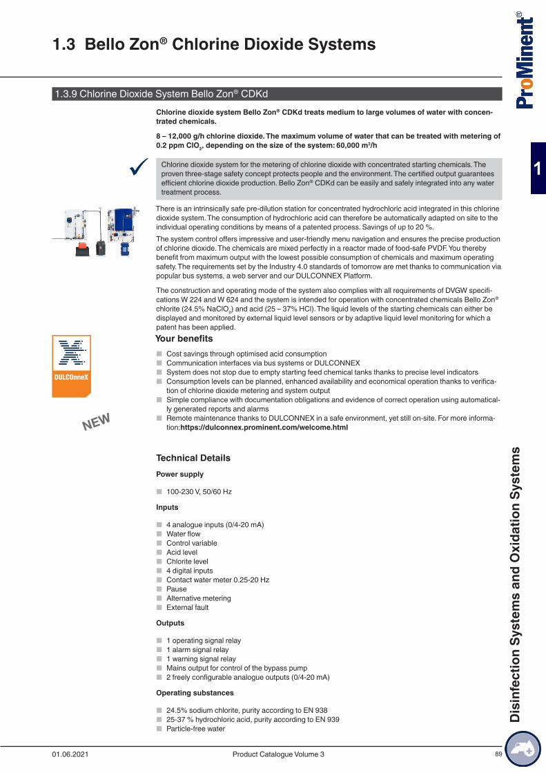
89
1.3.9 Chlorine Dioxide System Bello Zon® CDKdChlorine dioxide system Bello Zon® CDKd treats medium to large volumes of water with concen-trated chemicals.
8 – 12,000 g/h chlorine dioxide. The maximum volume of water that can be treated with metering of 0.2 ppm ClO2, depending on the size of the system: 60,000 m3/h
9 Chlorine dioxide system for the metering of chlorine dioxide with concentrated starting chemicals. The proven three-stage safety concept protects people and the environment. The certified output guarantees efficient chlorine dioxide production. Bello Zon® CDKd can be easily and safely integrated into any water treatment process.
There is an intrinsically safe pre-dilution station for concentrated hydrochloric acid integrated in this chlorine dioxide system. The consumption of hydrochloric acid can therefore be automatically adapted on site to the individual operating conditions by means of a patented process. Savings of up to 20 %.The system control offers impressive and user-friendly menu navigation and ensures the precise production of chlorine dioxide. The chemicals are mixed perfectly in a reactor made of food-safe PVDF. You thereby benefit from maximum output with the lowest possible consumption of chemicals and maximum operating safety. The requirements set by the Industry 4.0 standards of tomorrow are met thanks to communication via popular bus systems, a web server and our DULCONNEX Platform.
The construction and operating mode of the system also complies with all requirements of DVGW specifi-cations W 224 and W 624 and the system is intended for operation with concentrated chemicals Bello Zon® chlorite (24.5% NaClO2) and acid (25 – 37% HCl). The liquid levels of the starting chemicals can either be displayed and monitored by external liquid level sensors or by adaptive liquid level monitoring for which a patent has been applied.Your benefits
■ Cost savings through optimised acid consumption ■ Communication interfaces via bus systems or DULCONNEX ■ System does not stop due to empty starting feed chemical tanks thanks to precise level indicators ■ Consumption levels can be planned, enhanced availability and economical operation thanks to verifica-
tion of chlorine dioxide metering and system output ■ Simple compliance with documentation obligations and evidence of correct operation using automatical-
ly generated reports and alarms ■ Remote maintenance thanks to DULCONNEX in a safe environment, yet still on-site. For more informa-
tion:https://dulconnex.prominent.com/welcome.html
Technical DetailsPower supply
■ 100-230 V, 50/60 Hz
Inputs
■ 4 analogue inputs (0/4-20 mA) ■ Water flow ■ Control variable ■ Acid level ■ Chlorite level ■ 4 digital inputs ■ Contact water meter 0.25-20 Hz ■ Pause ■ Alternative metering ■ External fault
Outputs
■ 1 operating signal relay ■ 1 alarm signal relay ■ 1 warning signal relay ■ Mains output for control of the bypass pump ■ 2 freely configurable analogue outputs (0/4-20 mA)
Operating substances
■ 24.5% sodium chlorite, purity according to EN 938 ■ 25-37 % hydrochloric acid, purity according to EN 939 ■ Particle-free water
1.3 Bello Zon® Chlorine Dioxide Systems
01.06.2021 Product Catalogue Volume 3
Dis
infe
ctio
n Sy
stem
s an
d O
xida
tion
Syst
ems
90
Degree of protection
■ IP 65
Bus communication options
■ Modbus TCP / DULCONNEX ■ Modbus RTU / DULCONNEX ■ Profibus DULCONNEX ■ Profinet DULCONNEX
Field of application
■ Municipal drinking water and waste water treatment ■ Industrial process and cooling water
Technical Data
Type Chlorine dioxide metering rate (min.…max./hour, min./day)*
Max. operat-ing pressure**
Operating tem-perature
Chlorite Dimensions of the bypass
connector g/h g/d bar °C DNCDKd 150 7.5…150 56 8 10…40 8x5 6x4 25CDKd 400 20…400 140 8 10…40 12x9 8x5 25CDKd 900 45…900 300 8 10…40 Pressure hose
nozzle d168x5 25
CDKd 2000 100…2,000 700 5 10…40 Pressure hose nozzle d20
12x9 40
CDKd 2800 140…2,800 700 5 15…40 Pressure hose nozzle
12x9 40
CDKd 7300 370…7,300 1,750 3 15…40 Pressure hose nozzle
Pressure hose nozzle d16
40
CDKd 12000 600…12,000 1,750 2 18…40 Pressure hose nozzle d32
Pressure hose nozzle d16
40
* The metering figures relate to 5 or 2 bar back pressure and an ambient temperature of 20 °C. The minimum capacity per hour is based on the fact that when the system is operating at below 5 % of the nominal capacity, continuous metering is no longer possible as the pumping frequency of the metering pumps is then low. When plants are not operating continuously, the reactor contents should be changed at least twice a day. Therefore do not operate the system below the stated minimum capacity/day.
** at an ambient temperature of 35 °C
Type Dimensions H x W x D (approx.)*
Weight Supply voltage 230 V**
Supply voltage 115 V**
Power con-sumption
without by-pass pump
Power con-sumption
with bypass pump
HCl*** NaClO2***
mm kg A A W W l/h l/hCDKd 150 1,300 x 1,000 x 250 89 3.9 1.7 110 640 0.9 0.9CDKd 400 1,675 x 900 x 460 119 3.9 1.8 160 690 2.5 2.5CDKd 900 1,920 x 920 x 520 131 4.2 2.3 210 740 5.6 5.6CDKd 2000 1,880 x 1,320 x 570 201 - 3.7 370 - 12.3 12.3CDKd 2800 1,880 x 1,320 x 570 201 - 3.7 370 - 17.3 17.3CDKd 7300 2,250 x 1,850 x 500 216 - 8.6 610 - 45.1 45.1CDKd 12000 2,250 x 1,850 x 500 216 - 8.6 610 - 74.1 74.1
* including main system, pre-dilution and rinse valve, without bypass pump and water feed section** 230 V figures with bypass pump (CDKd 150-900), 115 V figures without bypass pump*** Sodium chlorite (NaClO2) 24.5 %, purity in accordance with EN 938, hydrochloric acid 25-36%, purity in accordance with EN 939. The
chemical consumption may vary depending on the temperature. The hydrochloric acid consumption is calculated for a concentration of 30%. Up to 25% hydrochloric acid can be saved with the aid of automatic acid adjustment.
1.3 Bello Zon® Chlorine Dioxide Systems
01.06.2021Product Catalogue Volume 3
Dis
infe
ctio
n Sy
stem
s an
d O
xida
tion
Syst
ems
91
Ambient conditions:Permissible relative air humidity (non-condensing) max. 85% rel.Permissible ambient temperature 40 °CPermissible temperature of chemicals 10 … 35 °CStorage and transport temperature -10 … +40 °CDegree of protection IP 65
1.3 Bello Zon® Chlorine Dioxide Systems
01.06.2021 Product Catalogue Volume 3
Dis
infe
ctio
n Sy
stem
s an
d O
xida
tion
Syst
ems
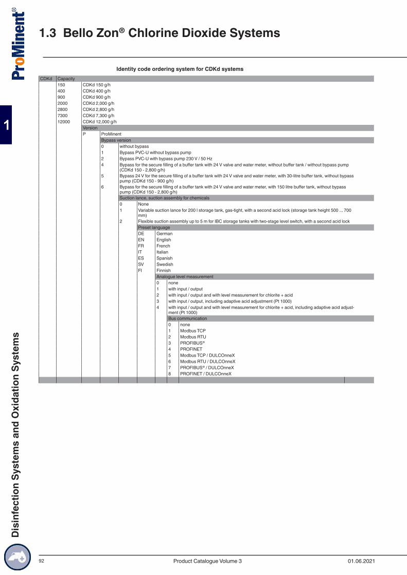
92
Identity code ordering system for CDKd systemsCDKd Capacity
150 CDKd 150 g/h400 CDKd 400 g/h900 CDKd 900 g/h2000 CDKd 2,000 g/h2800 CDKd 2,800 g/h7300 CDKd 7,300 g/h12000 CDKd 12,000 g/h
VersionP ProMinent
Bypass version0 without bypass1 Bypass PVC-U without bypass pump2 Bypass PVC-U with bypass pump 230 V / 50 Hz4 Bypass for the secure filling of a buffer tank with 24 V valve and water meter, without buffer tank / without bypass pump
(CDKd 150 - 2,800 g/h)5 Bypass 24 V for the secure filling of a buffer tank with 24 V valve and water meter, with 30-litre buffer tank, without bypass
pump (CDKd 150 - 900 g/h)6 Bypass for the secure filling of a buffer tank with 24 V valve and water meter, with 150 litre buffer tank, without bypass
pump (CDKd 150 - 2,800 g/h)Suction lance, suction assembly for chemicals0 None1 Variable suction lance for 200 l storage tank, gas-tight, with a second acid lock (storage tank height 500 ... 700
mm)2 Flexible suction assembly up to 5 m for IBC storage tanks with two-stage level switch, with a second acid lock
Preset languageDE GermanEN EnglishFR FrenchIT ItalianES SpanishSV SwedishFI Finnish
Analogue level measurement0 none1 with input / output2 with input / output and with level measurement for chlorite + acid3 with input / output, including adaptive acid adjustment (Pt 1000)4 with input / output and with level measurement for chlorite + acid, including adaptive acid adjust-
ment (Pt 1000)Bus communication0 none1 Modbus TCP2 Modbus RTU3 PROFIBUS®
4 PROFINET5 Modbus TCP / DULCOnneX6 Modbus RTU / DULCOnneX7 PROFIBUS® / DULCOnneX8 PROFINET / DULCOnneX
1.3 Bello Zon® Chlorine Dioxide Systems
01.06.2021Product Catalogue Volume 3
Dis
infe
ctio
n Sy
stem
s an
d O
xida
tion
Syst
ems
93
Maintenance kits for Bello Zon® chlorine dioxide systems type CDKdThe spare parts kits include all wearing parts that need replacing in the course of regular maintenance.
Order no.Maintenance kit, complete CDKd 150 1105953Maintenance kit, complete CDKd 400 1105954Maintenance kit, complete CDKd 900 1105955Maintenance kit, complete CDKd 2000 1105956Maintenance kit, complete CDKd 2800 1105957Maintenance kit, complete CDKd 7300 1105958Maintenance kit, complete CDKd 12000 1105959
Additional spare parts are listed in the operation instructions for the systems.
Maintenance Kits for Bello Zon® Type CDK Chlorine Dioxide SystemsThe spare parts kits include all wearing parts that need replacing in the course of regular maintenance.
Order no.Maintenance kit, complete CDKc 150 (type 20) 1043841Maintenance kit, complete CDKc 170 (type 02) 1036454Maintenance kit, complete CDKc 400 (type 21) 1043842Maintenance kit, complete CDKc 420 (type 04) 1036455Maintenance kit, complete CDKc 900 (type 22) 1043843Maintenance kit, complete CDKc 900 (type 06) 1036456Maintenance kit, complete CDKc 2000 (type 23) 1043864Maintenance kit, complete CDKc 2100 (type 08) 1036457Maintenance kit, complete CDKc 2800 (type 24) 1043865Maintenance kit, complete CDKc 3000 (type 10) 1036458Maintenance kit, complete CDKc 7500 (type 25) 1043866Maintenance kit, complete CDKc 7500 (type 12) 1036459Maintenance kit, complete CDKc 12000 (type 26) 1043867Maintenance kit, complete CDKc 12000 (type 14) 1040079
Additional spare parts are listed in the operation instructions for the systems.
Maintenance kits for Bello Zon® chlorine dioxide systems type CDKaThe spare parts kits include all wearing parts that need replacing in the course of regular maintenance.
Order no.Maintenance kit, complete 230 V CDKa 150 740740Maintenance kit, complete 230 V CDKa 420 740743Maintenance kit, complete 230 V CDKa 750 1000172Maintenance kit, complete 230 V CDKa 1500 1000856Maintenance kit, complete 230 V CDKa 6000 1004814Maintenance kit, complete 230 V CDKa 10000 1006647Maintenance kit, complete 115 V CDKa 150 740741Maintenance kit, complete 115 V CDKa 420 740744Maintenance kit, complete 115 V CDKa 750 1000173Maintenance kit, complete 115 V CDKa 1500 1000855Maintenance kit, complete 115 V CDKa 6000 1004815
Additional spare parts are listed in the operation instructions for the systems.
1.3 Bello Zon® Chlorine Dioxide Systems
01.06.2021 Product Catalogue Volume 3
Dis
infe
ctio
n Sy
stem
s an
d O
xida
tion
Syst
ems
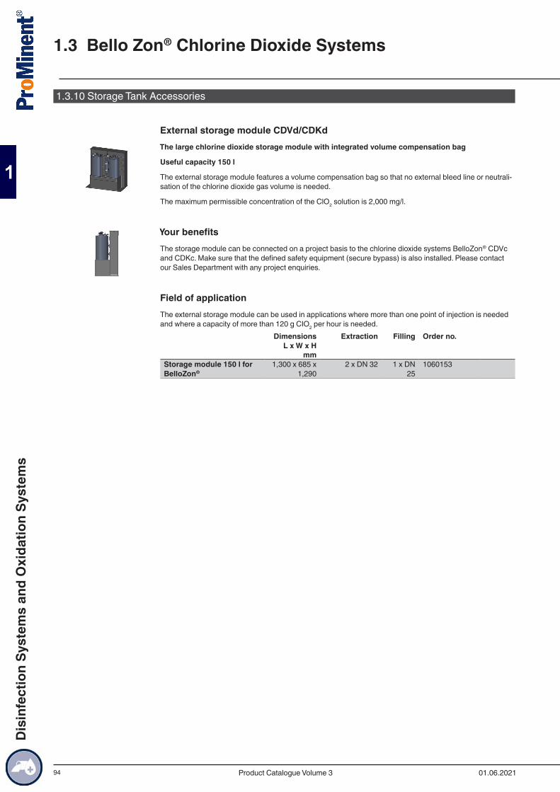
94
1.3.10 Storage Tank Accessories
External storage module CDVd/CDKdThe large chlorine dioxide storage module with integrated volume compensation bag
Useful capacity 150 l
The external storage module features a volume compensation bag so that no external bleed line or neutrali-sation of the chlorine dioxide gas volume is needed.
The maximum permissible concentration of the ClO2 solution is 2,000 mg/l.
Your benefitsThe storage module can be connected on a project basis to the chlorine dioxide systems BelloZon® CDVc and CDKc. Make sure that the defined safety equipment (secure bypass) is also installed. Please contact our Sales Department with any project enquiries.
Field of applicationThe external storage module can be used in applications where more than one point of injection is needed and where a capacity of more than 120 g CIO2 per hour is needed.
Dimensions L x W x H
Extraction Filling Order no.
mm Storage module 150 l for BelloZon®
1,300 x 685 x 1,290
2 x DN 32 1 x DN 25
1060153
1.3 Bello Zon® Chlorine Dioxide Systems
01.06.2021Product Catalogue Volume 3
Dis
infe
ctio
n Sy
stem
s an
d O
xida
tion
Syst
ems
95
1.3.11 Bypass Line Accessories
Premixers Made of PVCThe pre-mixers of types CDVb 15-120 are permanently integrated in the system provided they were ordered using an identity code. With CDVb 220, the pre-mixer can also be ordered using an identity code, but is then supplied loose with the system. With all other systems, the pre-mixer can be ordered in part using an identity code and in part separately. The scope of delivery for the pre-mixer includes PVC threaded connectors, screw clamps and other mounting material. With CDVa 2000 and CDKa 1500–10000, the pre-mixer com-prises two parts.Plant Volume Length Connection nomi-
nal diameterOrder no.
l mm CDVb 220, CDKa 150
1.5 594 DN 25 740649
CDVa 400, CDKa 420
4.5 756 DN 25 740650
CDVa 600, CDKa 750
7.0 1,306 DN 32 740832
CDVa 2000, CDKa 1500
13.4 1,316 DN 40 1001000
CDKa 6000/10000 13.4 1,330 DN 50 1003121
Bypass PumpBooster pumps made of cast iron or stainless steel (SS) for operation in the bypass line. Electrical design 220 – 230 V, 50 Hz, with integrated overload protection.
Consider the bypass flow required when selecting a suitable bypass pump. The following flow data is recom-mended for the different systems:
System type Bypass line Diameter
(mm)Flow (m3/h)
CDV 15 - 600 DN 25 32 0.5-2CDV 2,000 DN 40 50 2-10CDKa 150 - 420
DN 25 32 0.5-2
CDKa 750 DN 32 40 1-3.5CDKa 1,500 DN 40 50 1.5-10CDKa 6,000 - 10,000
DN 50 63 6-10
CDKc 150 - 900
DN 25 32 0.5-2
CDKc 2,000 - 2,800
DN 40 50 2-10
CDKc 7,300 DN 40 50 6-10CDKc 12,000 DN 40 50 10-15
Use PVC as the material for the bypass. The thickness should at least correspond to the pressure range PN 10, or even better PN 16 (bar).Type Connection suction/
discharge sideMate-
rialPump
capacity at 2 bar
Nom-inal
rating
Nominal current
Order no.
G-DN m3/h W A ZHM 3 RP 1”/1” SS 1.2 500 2.3 1051081
Important: Do not allow pump to come into contact with ClO2!
1.3 Bello Zon® Chlorine Dioxide Systems
01.06.2021 Product Catalogue Volume 3
Dis
infe
ctio
n Sy
stem
s an
d O
xida
tion
Syst
ems
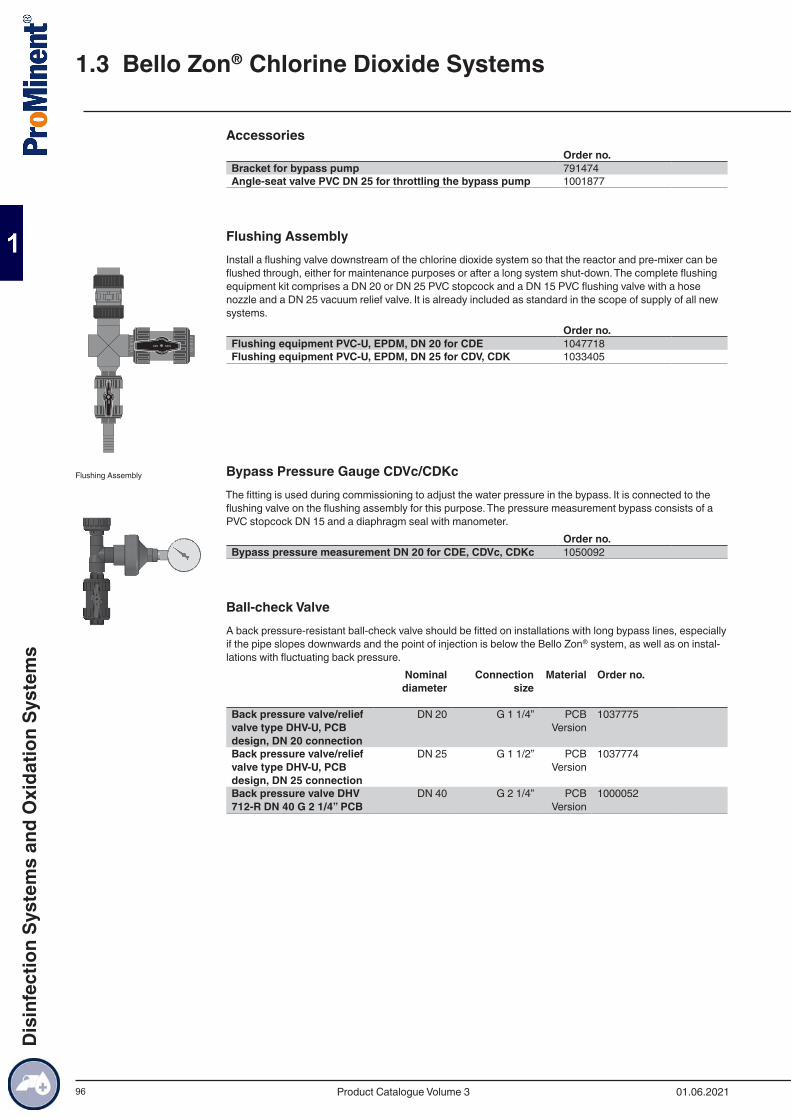
96
AccessoriesOrder no.
Bracket for bypass pump 791474Angle-seat valve PVC DN 25 for throttling the bypass pump 1001877
Flushing AssemblyInstall a flushing valve downstream of the chlorine dioxide system so that the reactor and pre-mixer can be flushed through, either for maintenance purposes or after a long system shut-down. The complete flushing equipment kit comprises a DN 20 or DN 25 PVC stopcock and a DN 15 PVC flushing valve with a hose nozzle and a DN 25 vacuum relief valve. It is already included as standard in the scope of supply of all new systems.
Order no.Flushing equipment PVC-U, EPDM, DN 20 for CDE 1047718Flushing equipment PVC-U, EPDM, DN 25 for CDV, CDK 1033405
Bypass Pressure Gauge CDVc/CDKcThe fitting is used during commissioning to adjust the water pressure in the bypass. It is connected to the flushing valve on the flushing assembly for this purpose. The pressure measurement bypass consists of a PVC stopcock DN 15 and a diaphragm seal with manometer.
Order no.Bypass pressure measurement DN 20 for CDE, CDVc, CDKc 1050092
Ball-check ValveA back pressure-resistant ball-check valve should be fitted on installations with long bypass lines, especially if the pipe slopes downwards and the point of injection is below the Bello Zon® system, as well as on instal-lations with fluctuating back pressure.
Nominal diameter
Connection size
Material Order no.
Back pressure valve/relief valve type DHV-U, PCB design, DN 20 connection
DN 20 G 1 1/4” PCB Version
1037775
Back pressure valve/relief valve type DHV-U, PCB design, DN 25 connection
DN 25 G 1 1/2” PCB Version
1037774
Back pressure valve DHV 712-R DN 40 G 2 1/4” PCB
DN 40 G 2 1/4” PCB Version
1000052
Flushing Assembly
1.3 Bello Zon® Chlorine Dioxide Systems
01.06.2021Product Catalogue Volume 3
Dis
infe
ctio
n Sy
stem
s an
d O
xida
tion
Syst
ems
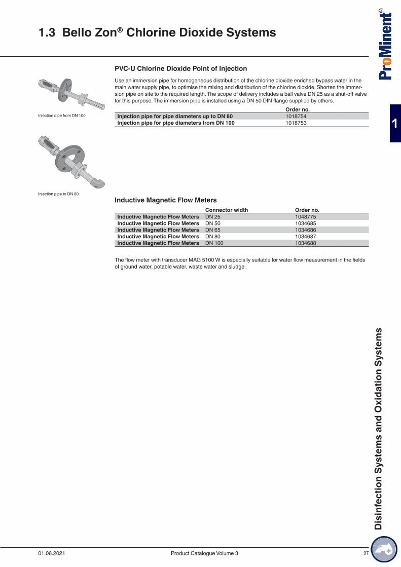
97
PVC-U Chlorine Dioxide Point of InjectionUse an immersion pipe for homogeneous distribution of the chlorine dioxide enriched bypass water in the main water supply pipe, to optimise the mixing and distribution of the chlorine dioxide. Shorten the immer-sion pipe on site to the required length. The scope of delivery includes a ball valve DN 25 as a shut-off valve for this purpose. The immersion pipe is installed using a DN 50 DIN flange supplied by others.
Order no.Injection pipe for pipe diameters up to DN 80 1018754Injection pipe for pipe diameters from DN 100 1018753
Inductive Magnetic Flow MetersConnector width Order no.
Inductive Magnetic Flow Meters DN 25 1048775Inductive Magnetic Flow Meters DN 50 1034685Inductive Magnetic Flow Meters DN 65 1034686Inductive Magnetic Flow Meters DN 80 1034687Inductive Magnetic Flow Meters DN 100 1034688
The flow meter with transducer MAG 5100 W is especially suitable for water flow measurement in the fields of ground water, potable water, waste water and sludge.
Injection pipe from DN 100
Injection pipe to DN 80
1.3 Bello Zon® Chlorine Dioxide Systems
01.06.2021 Product Catalogue Volume 3
Dis
infe
ctio
n Sy
stem
s an
d O
xida
tion
Syst
ems

98
1.3.12 Chemical Supply Accessories
Suction Lances and AccessoriesSuction lances have a rigid construction that can be precisely adapted to the chemical tank. Suction assem-blies consist of flexible suction lines.
All suction lances and suction assemblies are made of PVC with FKM seals and are fitted with a foot valve and two-stage level switch including cable and round plug. Select relevant components from the ProMinent motor-driven metering pump accessories range for system types not listed here.
Suitable for system types Order no.Suction lance for connection to 5-60 litre non-reusable tank with 2 m long suction hose (6/4 mm)
CDVc 20-120, CDE 45-80 802077
Suction lance for connection to 5-60 litre non-reusable tank with 2 m long suction hose (6/4 mm)
CDLb 790650
Suction lance for connection to 5-60 litre non-reusable tank with 2 m long suction hose (8/5 mm)
CDVc 240-600, CDE 140 802078
Suction lance for connection to 200 litre drums with 3 m long suction hose (6/4 mm)
CDVc 20-120, CDE 45-80 802079
Suction lance for connection to 200 litre drums with 3 m long suction hose (6/4 mm)
CDLb 791563
Suction lance for connection to 200 litre drums with 3 m long suction hose (8/5 mm)
CDVc 240-600, CDE 140 802080
Flexible suction fitting with D55 screw cap and 5 m suction hose (6/4mm)
CDVc 20-120, CDE 45-80 1034602
Flexible suction fitting with D55 screw cap and 5 m suction hose (8/5 mm)
CDVc 240-600, CDE 140 1034644
Suction lance DN 25 PP for connection to 200 litre drums, excluding cable
CDVc 2000 1039397
Suction lance DN 25 PP for connection to 1,000 litre IBC container, excluding cable
CDVc 2000 1039399
Gas-tight suction lance for 200 litre drums with bleed valve, connection for 6/4 and 8/5 mm suction lines and connector for 6/4 mm return line
CDKc 150-2800 1036371
Gas-tight suction lance for 60-litre canister with bleed valve, connector for 6/4 and 8/5 mm suction line and connector for 6/4 mm return line
CDKc 150-2800 1030891
Flexible suction assembly with 5 m suction hose (6/4 mm) and gas-tight D55 screw cap with opening for a return line
CDKc 150-2800 1036174
Flexible suction assembly with 5 m suction hose (8/5 mm) and gas-tight D55 screw cap with opening for a return line
CDKc 150-2800 1036175
1.3 Bello Zon® Chlorine Dioxide Systems
01.06.2021Product Catalogue Volume 3
Dis
infe
ctio
n Sy
stem
s an
d O
xida
tion
Syst
ems
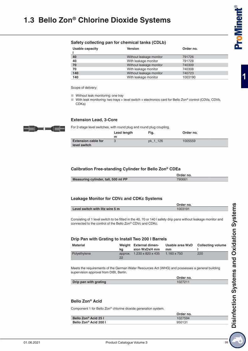
99
Safety collecting pan for chemical tanks (CDLb)Usable capacity Version Order no.l 40 Without leakage monitor 79172640 With leakage monitor 79172870 Without leakage monitor 74030970 With leakage monitor 740308140 Without leakage monitor 740723140 With leakage monitor 1003190
Scope of delivery:
■ Without leak monitoring: one tray ■ With leak monitoring: two trays + level switch + electronics card for Bello Zon® control (CDVa, CDVb,
CDKa)
Extension Lead, 3-CoreFor 2-stage level switches, with round plug and round plug coupling. Lead length Fig. Order no. m Extension cable for level switch
3 pk_1_126 1005559
Calibration Free-standing Cylinder for Bello Zon® CDEaOrder no.
Measuring cylinder, tall, 500 ml PP 790661
Leakage Monitor for CDVc and CDKc SystemsOrder no.
Level switch with litz wire 5 m 1003191
Consisting of 1 level switch to be fitted in the 40, 70 or 140 l safety drip pans without leakage monitor and connected to the control of the Bello Zon® CDVc and CDKc.
Drip Pan with Grating to Install Two 200 l BarrelsMaterial Weight
kgExternal dimen-sion WxDxH mm
Usable area WxD mm
Collecting volume l
Polyethylene approx. 22
1.230 x 820 x 435 1.160 x 750 220
Meets the requirements of the German Water Resources Act (WHG) and possesses a general building supervision approval from DIBt, Berlin.
Order no.Drip pan with grating 1027211
Bello Zon® AcidComponent 1 for Bello Zon® chlorine dioxide generation system.
Order no.Bello Zon® Acid 25 l 1027594Bello Zon® Acid 200 l 950131
1.3 Bello Zon® Chlorine Dioxide Systems
01.06.2021 Product Catalogue Volume 3
Dis
infe
ctio
n Sy
stem
s an
d O
xida
tion
Syst
ems
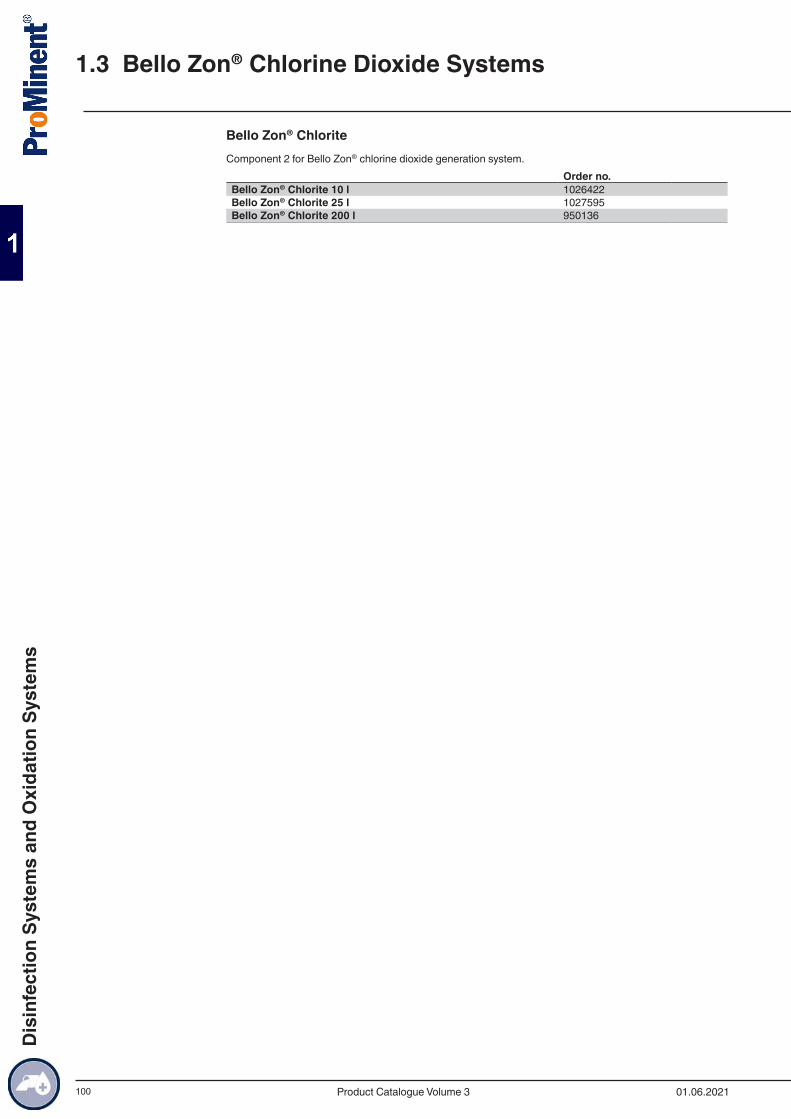
100
Bello Zon® ChloriteComponent 2 for Bello Zon® chlorine dioxide generation system.
Order no.Bello Zon® Chlorite 10 l 1026422Bello Zon® Chlorite 25 l 1027595Bello Zon® Chlorite 200 l 950136
1.3 Bello Zon® Chlorine Dioxide Systems
01.06.2021Product Catalogue Volume 3
Dis
infe
ctio
n Sy
stem
s an
d O
xida
tion
Syst
ems

101
1.3.13 Safety Accessories and Analysis
Gas detector GMA 22 chlorine dioxideThe GMA 22 chlorine dioxide gas detector is designed as a compact measuring and switching unit for moni-toring the ambient air for dangerous concentrations of chlorine dioxide.Type GMA 22 Chlorine dioxideWarning at approx. 0.2 ppm/vol%Alarm at approx. 1.0 ppm/vol%Permissible ambient tem-perature
0...45 °C
Protection class housing IP 64Dimensions (without PGs, without sensor) H x W x D
140 x 97 x 50 mm mm
Supply 100 – 240 V AC / 50 – 60 HzDC power connection 20 - 30 V DCMax. power consumption incl. sensor
20 W
Warm-up phase max. 150 s“Warning” relay contact, latching
250 V ; 3 A
“Alarm” relay contact, latching
250 V ; 3 A
“Horn” relay contact, latch-ing, can be acknowledged
250 V ; 3 A
Sensor measuring principle electrochemical Maximum sensor life 2 a
Order no.Gas detector GMA 22/1, 230 V including 1 transmitter with ClO2 sensor and 10 m connecting cable
1117291
Gas detector GMA 22/1, 24 V DC including 1 transmitter with ClO2 sensor and 10 m connecting cable
1117304
Gas detector GMA 22/2, 230 V including 2 transmitters with ClO2 sensor and 10 m connecting cable
1117308
Gas detector GMA 22/2, 24 V DC including 2 transmitters with ClO2 sensor and 10 m connecting cable
1117311
Replacement sensor for chlorine, chlorine dioxide, ozone * 1117331
* Sensor storage at 4 °C... 10 °C
Accessories for connecting a second sensorOrder no.
Connecting cable 5x0.25 mm² 10 m 1117330
Flash light-hornCombined horn and red warning lamp. IP 65 housing made of impact-resistant grey polycarbonate with a transparent polycarbonate dome. Rating values: 230 V AC, 50 mA.
Order no.Flash light-horn, red with continuous tone 1083160
Warning label for chlorine dioxide systemSoft PVC film, yellow/black, 300 x 200 mm, self-adhesive.
1.3 Bello Zon® Chlorine Dioxide Systems
01.06.2021 Product Catalogue Volume 3
Dis
infe
ctio
n Sy
stem
s an
d O
xida
tion
Syst
ems
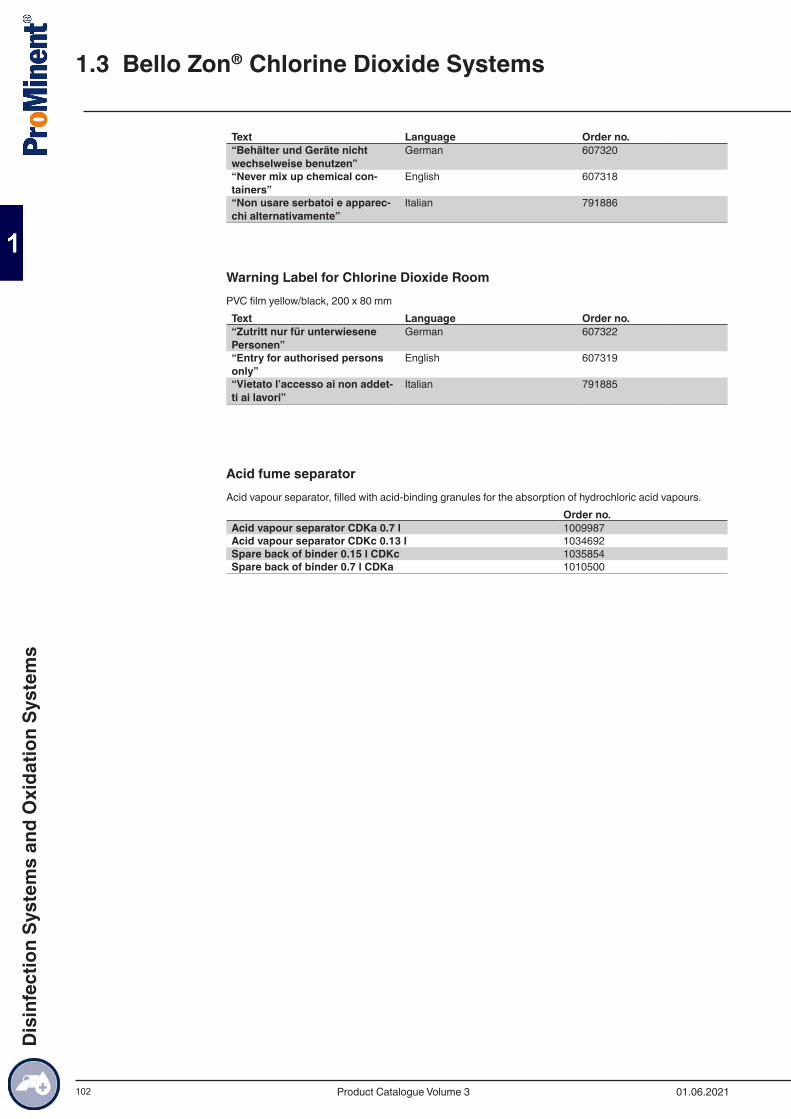
102
Text Language Order no.“Behälter und Geräte nicht wechselweise benutzen”
German 607320
“Never mix up chemical con-tainers”
English 607318
“Non usare serbatoi e apparec-chi alternativamente”
Italian 791886
Warning Label for Chlorine Dioxide RoomPVC film yellow/black, 200 x 80 mmText Language Order no.“Zutritt nur für unterwiesene Personen”
German 607322
“Entry for authorised persons only”
English 607319
“Vietato l’accesso ai non addet-ti ai lavori”
Italian 791885
Acid fume separatorAcid vapour separator, filled with acid-binding granules for the absorption of hydrochloric acid vapours.
Order no.Acid vapour separator CDKa 0.7 l 1009987Acid vapour separator CDKc 0.13 l 1034692Spare back of binder 0.15 l CDKc 1035854Spare back of binder 0.7 l CDKa 1010500
1.3 Bello Zon® Chlorine Dioxide Systems
01.06.2021Product Catalogue Volume 3
Dis
infe
ctio
n Sy
stem
s an
d O
xida
tion
Syst
ems

103
Photometers DT1, DT2 and DT4
■ Portable, compact photometer ■ Simple operation with text support ■ Safe, simple measurement of chlorine, chlorine dioxide, fluoride, chlorite, H2O2, bromine, ozone, pH and
cyanuric acid ■ Calibratable
Measuring ranges of the DT1B
0.05 … 6.0 mg/l free chlorine (DPD1) + total chlorine (DPD1+3) 5 … 200 mg/l free chlorine (high range) 0.1 … 13.0 mg/l bromine (DPD1) 0.05 … 11 mg/l chlorine dioxide (DPD1) 0.03 … 4.0 mg/l ozone (DPD4) 6.5 … 8.4 pH (phenol red) 1 … 80 mg/l cyanuric acid
Measuring ranges of the DT2C
0.05 … 2.0 mg/l fluoride 0.05 … 6.0 mg/l free chlorine and total chlorine 0.05 … 11.0 mg/l chlorine dioxide
DT4 ranges 0.03 … 2.5 mg/l chlorite 0.05 … 11 mg/l chlorine dioxide 0.05 … 6 mg/l chlorine
Measuring tolerance Dependent upon measured value and measuring methodBattery 4 AA/LR6 batteriesMin. ambient temperature 5 °CMax. ambient temperature 40 °CRelative humidity 30 … 90% (non-condensing)Material Housing: ABS
Keypad: Polycarbonate filmDimensions L x W x H 190 x 110 x 55Weight 0.4 kg
Description Order no.Photometer DT1B Complete with carrying case 1039315Photometer DT2C Complete with carrying case 1039316Photometer DT4B Complete with carrying case 1039318
The standard delivery package for the photometers includes accessories, cuvettes and reagents
Case for Chlorine Dioxyde Depletion TestThe case contains the equipment needed for a ClO2 depletion test. A photometer and the starting chemicals are also needed.
Important: Only allow trained personnel to use the case!Order no.
Measuring case 1042890
Photometer
1.3 Bello Zon® Chlorine Dioxide Systems
01.06.2021 Product Catalogue Volume 3
Dis
infe
ctio
n Sy
stem
s an
d O
xida
tion
Syst
ems

104
Consumables for AnalysisOrder no.
DPD1 tablets, 100 tablets 1115981DPD3 tablets, 100 tablets 1115982Glycine tablets, 20 pieces 1115983Phenol red tablets 100 pieces 1116004Cyanuric acid tablets, 100 tablets 1039744SPADNS reagent, 250 ml for fluoride detection 1010381Calibration standard fluoride 1 mg/l, for calibration of the pho-tometer during fluoride determination
1010382
3 pieces replacement cuvettes; round cuvettes with lid for DPD, phenol red and cyanuric acid detection (DT1, DT1B, DT4, DT4B, DT2B, DT2C)
1007566
3 pieces replacement cuvettes for fluoride detection (DT2B and DT2C)
1010396
Chlorine dioxide tablets No. 1, 250 no. 1039732Chlorine dioxide tablets No. 2, 250 no. 1039733Chlorine HR tablets, 100 pieces 1075056Acidifying tablets, 100 pieces 1075057
DPD reagents for measuring excess chlorine, ozone or chlorine dioxide in the water in combination with Lovibond comparator.
Volume Order no.DPD tablets no. 1 100 501319DPD tablets no. 2 100 501320DPD tablets no. 3 100 501321DPD tablets no. 4 100 501322
1.3 Bello Zon® Chlorine Dioxide Systems
01.06.2021Product Catalogue Volume 3
Dis
infe
ctio
n Sy
stem
s an
d O
xida
tion
Syst
ems

105
1.3.14 DULCONNEX - digital fluid management
Location-independent system monitoring in real timeYou always have all the key data and measured values in sight at all times with DULCONNEX. Monitor and document the status of your system in real time. Check your unit data, regardless of where you are, safely and reliably when you’re out and about. Simply use the terminal device of your choice: smartphone, tablet or PC.
Refer to our catalogue or website for more information and references.
1.3 Bello Zon® Chlorine Dioxide Systems
01.06.2021 Product Catalogue Volume 3
Dis
infe
ctio
n Sy
stem
s an
d O
xida
tion
Syst
ems
106
1.4.1 Electrolysis Systems CHLORINSITUWith electrolysis, chlorine and sodium hydroxide solution are produced in situ from salt water using electric current.
In theopen electrolysis cell (type CHLORINSITU IIa), the electrochemical reaction takes place in a flow chamber, so that the freshly produced chlorine gas immediately reacts with the sodium hydroxide solution also produced to form sodium hypochlorite. A saturated brine is used as a salt solution, which is produced in a separate salt dissolving tank from salt of a defined quality. The benefit of the open electrolysis cell lies in the simple construction of the equipment, its ease of maintenance and low investment compared tomem-brane electrolysis systems. The disadvantage is the low yield of the salt solution, higher entrainment of chloride into the water to be treated, higher power consumption and low chlorine concentrations in the end product.
Inmembrane electrolysis, the electrochemical reaction takes place in two electrode chambers, separated by a diaphragm, so that the formation of the freshly produced chlorine gas and sodium hydroxide solution is physically separated. Systems of types CHLORINSITU III and CHLORINSITU III Compact bring the reaction mixtures of both electrode chambers together again after the electrochemical reaction to produce a stock solution of sodium hypochlorite (25 g/l FAC), which can be stored temporarily and metered as needed.
With systems of types CHLORINSITU IV Compact and CHLORINSITU V, the highly pure chlorine gas is fed directly into the water to be treated through an injector and under constant vacuum. It then dissolves as hy-pochlorous acid. In systems of type CHLORINSITU V Plus, any excess chlorine gas produced is combined with the sodium hydroxide solution, as in the CHLORINSITU III system, to form sodium hypochlorite and is then stored temporarily. The systems therefore only need to be designed for average chlorine demand, as peaks in capacity can be compensated for from the sodium hypochlorite supply tank. In all systems of types CHLORINSITU IV Compact, CHLORINSITU V and CHLORINSITU V Plus, the sodium hydroxide solution produced during electrolysis is stored temporarily and metered in, as required, to correct the pH value.
The benefit of membrane systems lies in their excellent efficiency (85 % brine yield) and minimal entrain-ment of chloride compared to open electrolysis cells. In systems of types CHLORINSITU V and CHLORIN-SITU V Plus, the entrainment of chloride and chlorate from the electrolysis cell into the water to be treated can be avoided completely. In membrane cell electrolysis systems for producing sodium hypochlorite, the higher yield results in solutions with a significantly higher chlorine content than is the case with open elec-trolysis cells.
■ Disinfection from natural sodium chloride ■ No handling of hazardous chemicals ■ High-purity product, thanks to production in situ and short temporary storage periods ■ The chlorine gas is generated under a constant vacuum, absolutely reliably and with maximum operating
safety, thanks to the units being designed as vacuum systems ■ Chlorine generation and pH correction with one system (CHLORINSITU IV Compact, CHLORINSITU V
and CHLORINSITU V Plus) ■ Improved working conditions for operating personnel ■ No risk of confusing dangerous chemical tanks
1.4 Electrolysis systems CHLORINSITU and DULCO®-
Lyse
01.06.2021Product Catalogue Volume 3
Dis
infe
ctio
n Sy
stem
s an
d O
xida
tion
Syst
ems
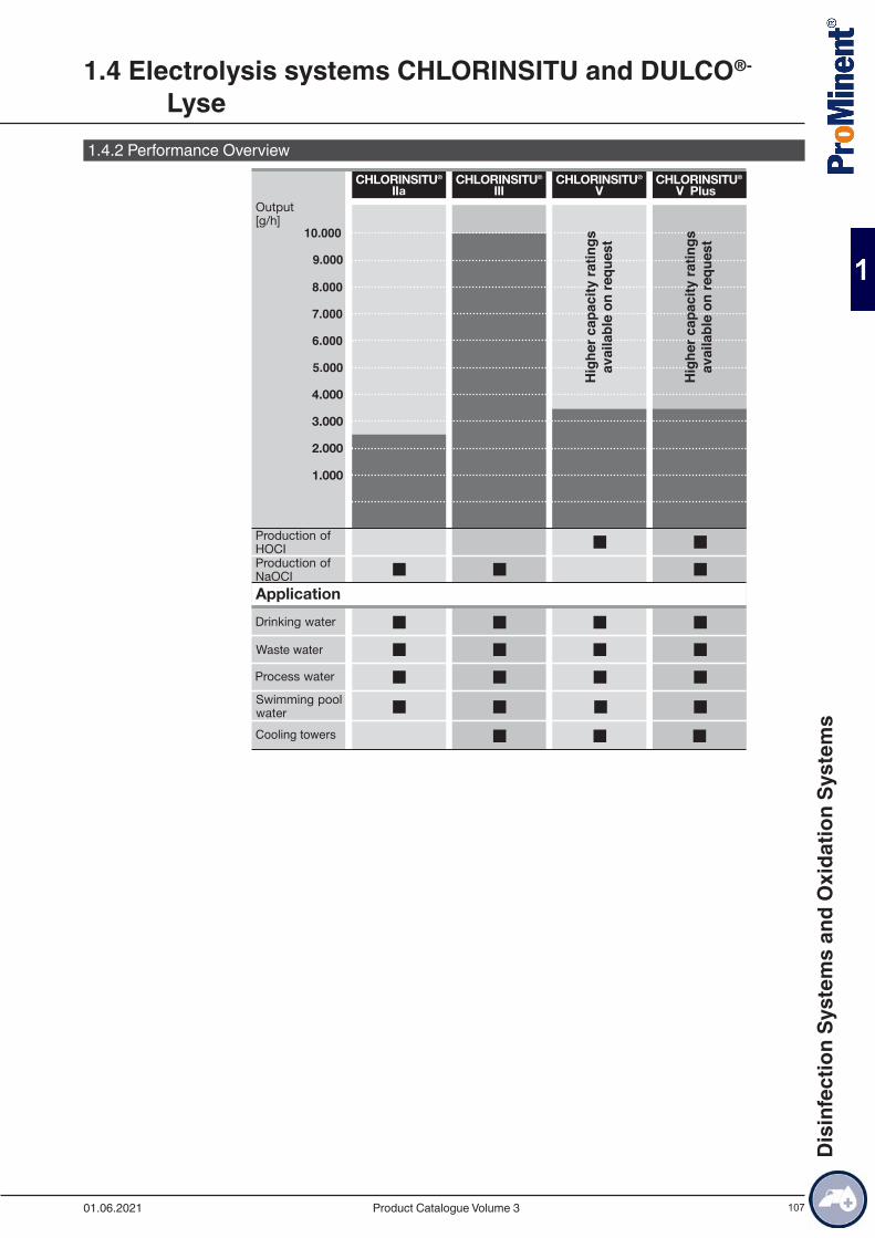
107
1.4.2 Performance Overview
1.4 Electrolysis systems CHLORINSITU and DULCO®-
Lyse
01.06.2021 Product Catalogue Volume 3
Dis
infe
ctio
n Sy
stem
s an
d O
xida
tion
Syst
ems
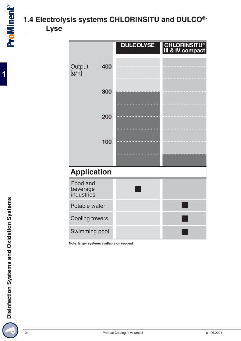
108
ApplicationFood andbeverage industries
Potable water
Cooling towers
Swimming pool
Note: larger systems available on request
1.4 Electrolysis systems CHLORINSITU and DULCO®-
Lyse
01.06.2021Product Catalogue Volume 3
Dis
infe
ctio
n Sy
stem
s an
d O
xida
tion
Syst
ems
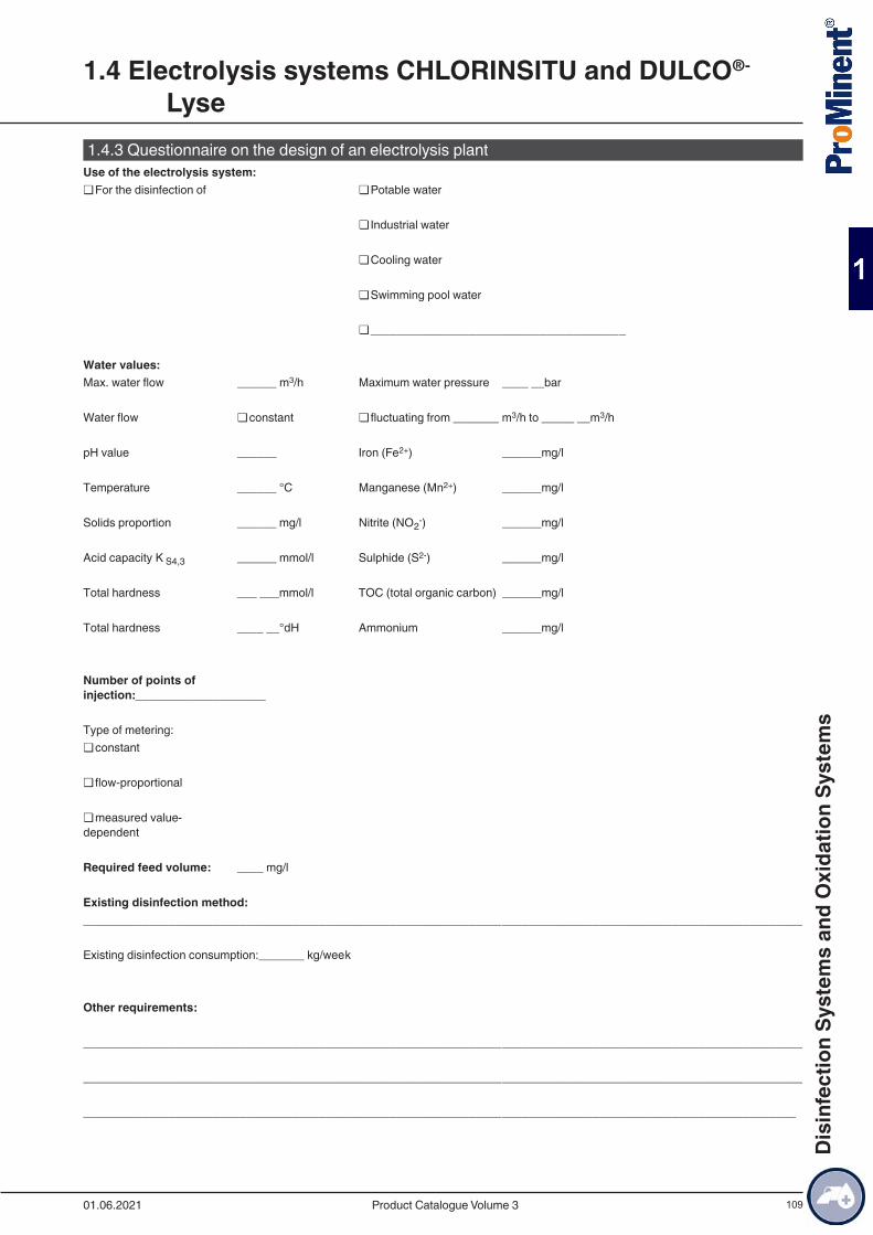
109
1.4.3 Questionnaire on the design of an electrolysis plant
1.4 Electrolysis systems CHLORINSITU and DULCO®-
Lyse
01.06.2021 Product Catalogue Volume 3
Dis
infe
ctio
n Sy
stem
s an
d O
xida
tion
Syst
ems

110
1.4.4 Electrolysis System CHLORINSITU IIa 60 – 2,500 g/hElectrolysis system CHLORINSITU IIa with open cell electrolysis: improved efficiency through innovative design.
Output 60 – 2,500 g/h of chlorine
9 CHLORINSITU IIa is a compact on-site electrolysis system for the production of a low-chlorate hypochlo-rite solution from sodium chloride and electrical energy. A key advantage is its simple process manage-ment and excellent system safety through integrated ventilation and bleeding.
The CHLORINSITU IIa product range combines the proven and durable design of the undivided electrolysis cell with an innovative design. An exceptional quality of hypochlorite solution is achieved when the salt and power output is increased. The chlorate content of the product is significantly below the limit value specified in EN 901.
The electrolysis system is perfectly equipped for all safe water disinfection with an increased capacity of up to 2,500 g of chlorine per hour.
All relevant system components are accommodated in a space-saving housing. Integrated hydrogen drain-age enables the system to be installed without any need for additional ventilation at the installation site.
The softener and a 50-litre product tank are installed in the system housing with systems up to 300 g/h. An integrated metering pump circulates the chlorine from the tank directly to the application or into a larger storage tank.
An H2 deaerator dissolves the hydrogen directly from the hypochlorite with systems above 625 g/h. The hydrogen-free product is pumped by an integrated pump into an external product tank. The product pump is also capable of pumping across height differences of up to 7 m. Customised metering stations supply the points of injection.
The external product tank does not require additional hydrogen bleeding. There are therefore no additional costs relating to installation and operation.
The system is immediately ready for use, thanks to its plug-and-play concept. Operation of the electrolysis system has been consciously kept simple.
Your benefits
■ Durable design, reliable technology ■ Low-chlorate product (below the EN 901 limit value) ■ High output: only 3.0 kg of salt per kg of chlorine ■ Reduced energy consumption: only 4 kWh/kg chlorine ■ Minimal maintenance and ease of operation ■ System monitoring in real time from any location via DULCONNEX Platform: improved process reliability,
overall reliability and transparency through real-time monitoring, individual alarms and automated reports
Technical Details
■ efficient undivided electrolytic cell ■ corrosion-proof housing with integrated ventilation fan ■ control with multicoloured touch panel ■ optional remote maintenance module ■ salt dissolving storage tank included in the scope of delivery ■ integrated 50-litre product storage tank with optional diaphragm metering pump for the metering of the
chlorine solution (up to 300 g/h) ■ integrated softener (up to 300 g/h)
Field of application
■ Potable water ■ Swimming pool water ■ Process water
1.4 Electrolysis systems CHLORINSITU and DULCO®-
Lyse
01.06.2021Product Catalogue Volume 3
Dis
infe
ctio
n Sy
stem
s an
d O
xida
tion
Syst
ems
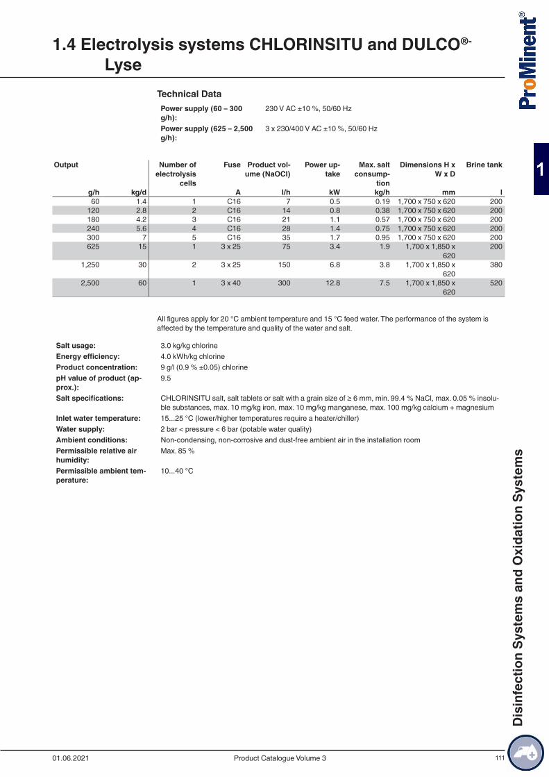
111
Technical DataPower supply (60 – 300 g/h):
230 V AC ±10 %, 50/60 Hz
Power supply (625 – 2,500 g/h):
3 x 230/400 V AC ±10 %, 50/60 Hz
Output Number of
electrolysis cells
Fuse Product vol-ume (NaOCl)
Power up-take
Max. salt consump-
tion
Dimensions H x W x D
Brine tank
g/h kg/d A l/h kW kg/h mm l60 1.4 1 C16 7 0.5 0.19 1,700 x 750 x 620 200
120 2.8 2 C16 14 0.8 0.38 1,700 x 750 x 620 200180 4.2 3 C16 21 1.1 0.57 1,700 x 750 x 620 200240 5.6 4 C16 28 1.4 0.75 1,700 x 750 x 620 200300 7 5 C16 35 1.7 0.95 1,700 x 750 x 620 200625 15 1 3 x 25 75 3.4 1.9 1,700 x 1,850 x
620200
1,250 30 2 3 x 25 150 6.8 3.8 1,700 x 1,850 x 620
380
2,500 60 1 3 x 40 300 12.8 7.5 1,700 x 1,850 x 620
520
All figures apply for 20 °C ambient temperature and 15 °C feed water. The performance of the system is affected by the temperature and quality of the water and salt.
Salt usage: 3.0 kg/kg chlorineEnergy efficiency: 4.0 kWh/kg chlorineProduct concentration: 9 g/l (0.9 % ±0.05) chlorinepH value of product (ap-prox.):
9.5
Salt specifications: CHLORINSITU salt, salt tablets or salt with a grain size of ≥ 6 mm, min. 99.4 % NaCl, max. 0.05 % insolu-ble substances, max. 10 mg/kg iron, max. 10 mg/kg manganese, max. 100 mg/kg calcium + magnesium
Inlet water temperature: 15...25 °C (lower/higher temperatures require a heater/chiller)Water supply: 2 bar < pressure < 6 bar (potable water quality)Ambient conditions: Non-condensing, non-corrosive and dust-free ambient air in the installation roomPermissible relative air humidity:
Max. 85 %
Permissible ambient tem-perature:
10...40 °C
1.4 Electrolysis systems CHLORINSITU and DULCO®-
Lyse
01.06.2021 Product Catalogue Volume 3
Dis
infe
ctio
n Sy
stem
s an
d O
xida
tion
Syst
ems

112
Identity Code Ordering System for Electrolysis Systems CHLORINSITU IIaCIIa Type Output
0060 60 g/h0120 120 g/h0180 180 g/h0240 240 g/h0300 300 g/h0625 625 g/h1250 1,250 g/h2500 2,500 g/h
VersionP ProMinentS Non-standard
Mechanical design0 standardM modified
Electrical Connection0 230 V, 50/60 Hz / 3x 230/400 VAC; 50 Hz (625 – 2,500 g/h)
Softener0 None (only 625- 2500 g/h)1 with
Chlorine pump0 none1 with (60 – 300 g/h)
Communication interfaces0 none1 Remote Engineer (60 – 300 g/h)2 Modbus (625 – 2,500 g/h)
Additional options0 None1 with digital liquid level sensors for product tank (625 – 2,500 g/h)
Preset languageDE GermanEN EnglishFR FrenchES SpanishIT ItalianHR CroatianPL Polish
Maintenance sets for CHLORINSITU IIaOrder no.
Maintenance set 1-year 60 g/h 1097435Maintenance set 1-year 120 g/h 1097436Maintenance set 1-year 180 g/h 1097437Maintenance set 1-year 240 g/h 1097438Maintenance set 1-year 300 g/h 1097439Maintenance set 3-years 60 g/h 1097440Maintenance set 3-years 120 g/h 1097441Maintenance set 3-years 180 g/h 1097442Maintenance set 3-years 240 g/h 1097443Maintenance set 3-years 300 g/h 1097455
Spare parts for CHLORINSITU IIaOrder no.
Electrolysis cell CIIa 60 g/h 1098825
1.4 Electrolysis systems CHLORINSITU and DULCO®-
Lyse
01.06.2021Product Catalogue Volume 3
Dis
infe
ctio
n Sy
stem
s an
d O
xida
tion
Syst
ems
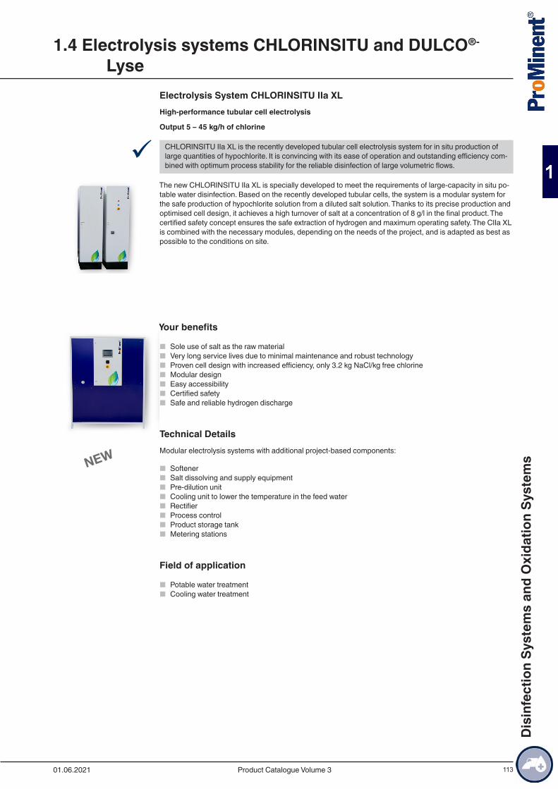
113
Electrolysis System CHLORINSITU IIa XLHigh-performance tubular cell electrolysis
Output 5 – 45 kg/h of chlorine
9 CHLORINSITU IIa XL is the recently developed tubular cell electrolysis system for in situ production of large quantities of hypochlorite. It is convincing with its ease of operation and outstanding efficiency com-bined with optimum process stability for the reliable disinfection of large volumetric flows.
The new CHLORINSITU IIa XL is specially developed to meet the requirements of large-capacity in situ po-table water disinfection. Based on the recently developed tubular cells, the system is a modular system for the safe production of hypochlorite solution from a diluted salt solution. Thanks to its precise production and optimised cell design, it achieves a high turnover of salt at a concentration of 8 g/l in the final product. The certified safety concept ensures the safe extraction of hydrogen and maximum operating safety. The CIIa XL is combined with the necessary modules, depending on the needs of the project, and is adapted as best as possible to the conditions on site.
Your benefits
■ Sole use of salt as the raw material ■ Very long service lives due to minimal maintenance and robust technology ■ Proven cell design with increased efficiency, only 3.2 kg NaCl/kg free chlorine ■ Modular design ■ Easy accessibility ■ Certified safety ■ Safe and reliable hydrogen discharge
Technical DetailsModular electrolysis systems with additional project-based components:
■ Softener ■ Salt dissolving and supply equipment ■ Pre-dilution unit ■ Cooling unit to lower the temperature in the feed water ■ Rectifier ■ Process control ■ Product storage tank ■ Metering stations
Field of application
■ Potable water treatment ■ Cooling water treatment
1.4 Electrolysis systems CHLORINSITU and DULCO®-
Lyse
01.06.2021 Product Catalogue Volume 3
Dis
infe
ctio
n Sy
stem
s an
d O
xida
tion
Syst
ems
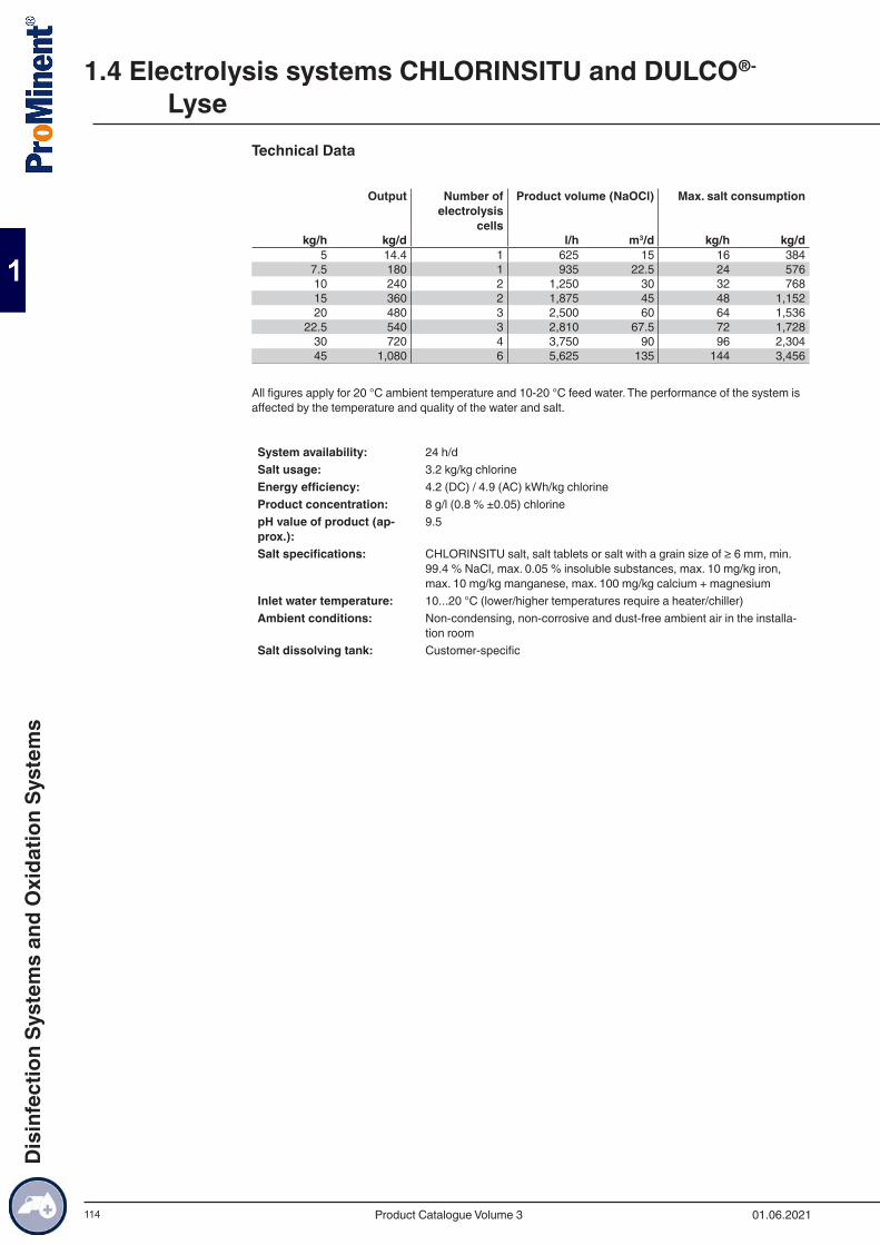
114
Technical Data
Output Number of electrolysis
cells
Product volume (NaOCl) Max. salt consumption
kg/h kg/d l/h m3/d kg/h kg/d5 14.4 1 625 15 16 384
7.5 180 1 935 22.5 24 57610 240 2 1,250 30 32 76815 360 2 1,875 45 48 1,15220 480 3 2,500 60 64 1,536
22.5 540 3 2,810 67.5 72 1,72830 720 4 3,750 90 96 2,30445 1,080 6 5,625 135 144 3,456
All figures apply for 20 °C ambient temperature and 10-20 °C feed water. The performance of the system is affected by the temperature and quality of the water and salt.
System availability: 24 h/dSalt usage: 3.2 kg/kg chlorineEnergy efficiency: 4.2 (DC) / 4.9 (AC) kWh/kg chlorineProduct concentration: 8 g/l (0.8 % ±0.05) chlorinepH value of product (ap-prox.):
9.5
Salt specifications: CHLORINSITU salt, salt tablets or salt with a grain size of ≥ 6 mm, min. 99.4 % NaCl, max. 0.05 % insoluble substances, max. 10 mg/kg iron, max. 10 mg/kg manganese, max. 100 mg/kg calcium + magnesium
Inlet water temperature: 10...20 °C (lower/higher temperatures require a heater/chiller)Ambient conditions: Non-condensing, non-corrosive and dust-free ambient air in the installa-
tion roomSalt dissolving tank: Customer-specific
1.4 Electrolysis systems CHLORINSITU and DULCO®-
Lyse
01.06.2021Product Catalogue Volume 3
Dis
infe
ctio
n Sy
stem
s an
d O
xida
tion
Syst
ems
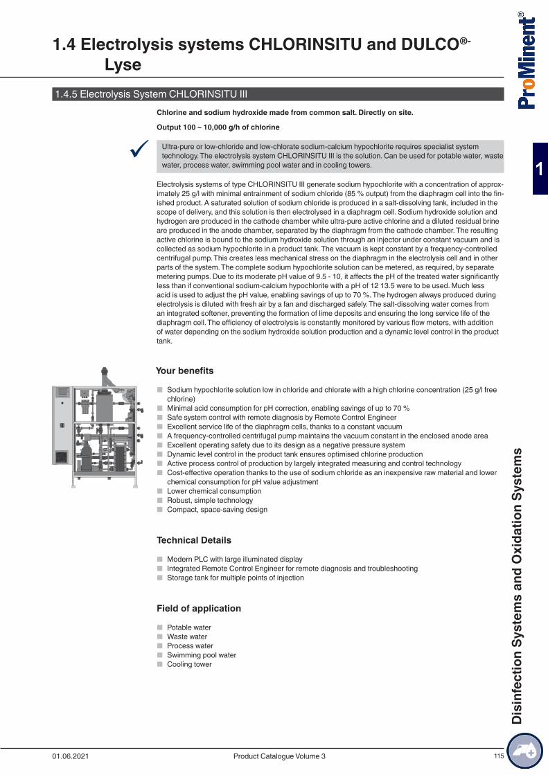
115
1.4.5 Electrolysis System CHLORINSITU III Chlorine and sodium hydroxide made from common salt. Directly on site.
Output 100 – 10,000 g/h of chlorine
9 Ultra-pure or low-chloride and low-chlorate sodium-calcium hypochlorite requires specialist system technology. The electrolysis system CHLORINSITU III is the solution. Can be used for potable water, waste water, process water, swimming pool water and in cooling towers.
Electrolysis systems of type CHLORINSITU III generate sodium hypochlorite with a concentration of approx-imately 25 g/l with minimal entrainment of sodium chloride (85 % output) from the diaphragm cell into the fin-ished product. A saturated solution of sodium chloride is produced in a salt-dissolving tank, included in the scope of delivery, and this solution is then electrolysed in a diaphragm cell. Sodium hydroxide solution and hydrogen are produced in the cathode chamber while ultra-pure active chlorine and a diluted residual brine are produced in the anode chamber, separated by the diaphragm from the cathode chamber. The resulting active chlorine is bound to the sodium hydroxide solution through an injector under constant vacuum and is collected as sodium hypochlorite in a product tank. The vacuum is kept constant by a frequency-controlled centrifugal pump. This creates less mechanical stress on the diaphragm in the electrolysis cell and in other parts of the system. The complete sodium hypochlorite solution can be metered, as required, by separate metering pumps. Due to its moderate pH value of 9.5 - 10, it affects the pH of the treated water significantly less than if conventional sodium-calcium hypochlorite with a pH of 12 13.5 were to be used. Much less acid is used to adjust the pH value, enabling savings of up to 70 %. The hydrogen always produced during electrolysis is diluted with fresh air by a fan and discharged safely. The salt-dissolving water comes from an integrated softener, preventing the formation of lime deposits and ensuring the long service life of the diaphragm cell. The efficiency of electrolysis is constantly monitored by various flow meters, with addition of water depending on the sodium hydroxide solution production and a dynamic level control in the product tank.
Your benefits
■ Sodium hypochlorite solution low in chloride and chlorate with a high chlorine concentration (25 g/l free chlorine)
■ Minimal acid consumption for pH correction, enabling savings of up to 70 % ■ Safe system control with remote diagnosis by Remote Control Engineer ■ Excellent service life of the diaphragm cells, thanks to a constant vacuum ■ A frequency-controlled centrifugal pump maintains the vacuum constant in the enclosed anode area ■ Excellent operating safety due to its design as a negative pressure system ■ Dynamic level control in the product tank ensures optimised chlorine production ■ Active process control of production by largely integrated measuring and control technology ■ Cost-effective operation thanks to the use of sodium chloride as an inexpensive raw material and lower
chemical consumption for pH value adjustment ■ Lower chemical consumption ■ Robust, simple technology ■ Compact, space-saving design
Technical Details
■ Modern PLC with large illuminated display ■ Integrated Remote Control Engineer for remote diagnosis and troubleshooting ■ Storage tank for multiple points of injection
Field of application
■ Potable water ■ Waste water ■ Process water ■ Swimming pool water ■ Cooling tower
1.4 Electrolysis systems CHLORINSITU and DULCO®-
Lyse
01.06.2021 Product Catalogue Volume 3
Dis
infe
ctio
n Sy
stem
s an
d O
xida
tion
Syst
ems
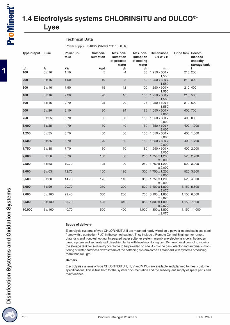
116
Technical DataPower supply 3 x 400 V (VAC/3P/N/PE/50 Hz)
Type/output Fuse Power up-take
Salt con-sumption
Max. con-sumption
of process water
Max. con-sumption of cooling
water
Dimensions L x W x H
Brine tank Recom-mended capacity storage tank
g/h A kW kg/d l/h l/h mm l l100 3 x 16 1.10 5 4 80 1,250 x 600 x
1,550210 200
200 3 x 16 1.50 10 8 80 1,250 x 600 x 1,550
210 300
300 3 x 16 1.90 15 12 100 1,250 x 600 x 1,550
210 400
400 3 x 16 2.30 20 16 100 1,250 x 600 x 1,550
210 500
500 3 x 16 2.70 25 20 125 1,250 x 600 x 1,550
210 600
600 3 x 20 3.10 30 24 125 1,650 x 600 x 2,000
400 700
750 3 x 25 3.70 35 30 150 1,650 x 600 x 2,000
400 800
1,000 3 x 25 4.70 50 40 150 1,650 x 600 x 2,000
400 1,200
1,250 3 x 35 5.70 60 50 150 1,650 x 600 x 2,000
400 1,500
1,500 3 x 35 6.70 70 60 180 1,650 x 600 x 2,000
400 1,700
1,750 3 x 35 7.70 80 70 180 1,650 x 600 x 2,000
400 2,000
2,000 3 x 50 8.70 100 80 200 1,750 x 1,200 x 2,000
520 2,200
2,500 3 x 63 10.70 125 100 250 1,750 x 1,200 x 2,000
520 3,000
3,000 3 x 63 12.70 150 120 300 1,750 x 1,200 x 2,000
520 3,300
3,500 3 x 80 14.70 175 140 350 1,750 x 1,200 x 2,000
520 4,000
5,000 3 x 90 20.70 250 200 500 3,100 x 1,800 x 2,070
1,150 5,800
7,000 3 x 100 29.40 350 280 700 3,100 x 1,800 x 2,070
1,150 6,000
8,500 3 x 130 35.70 425 340 850 4,300 x 1,800 x 2,070
1,150 7,500
10,000 3 x 160 40.70 500 400 1,000 4,300 x 1,800 x 2,070
1,150 11,000
Scope of delivery
Electrolysis systems of type CHLORINSITU III are mounted ready-wired on a powder-coated stainless steel frame with a controller (PLC) in the control cabinet. They include a Remote Control Engineer for remote diagnosis and troubleshooting, integrated water softener system, membrane electrolysis cells, hydrogen bleed system and separate salt dissolving tanks with level monitoring unit. Dynamic level control to monitor the storage tank for sodium hypochlorite to be provided on site. A chlorine gas detector and automatic mon-itoring of water hardness downstream of the softening system come as standard with systems producing more than 600 g/h.
Remark
Electrolysis systems of type CHLORINSITU II, III, V and V Plus are available and planned to meet customer specifications. This is true both for the system documentation and the subsequent supply of spare parts and maintenance.
1.4 Electrolysis systems CHLORINSITU and DULCO®-
Lyse
01.06.2021Product Catalogue Volume 3
Dis
infe
ctio
n Sy
stem
s an
d O
xida
tion
Syst
ems
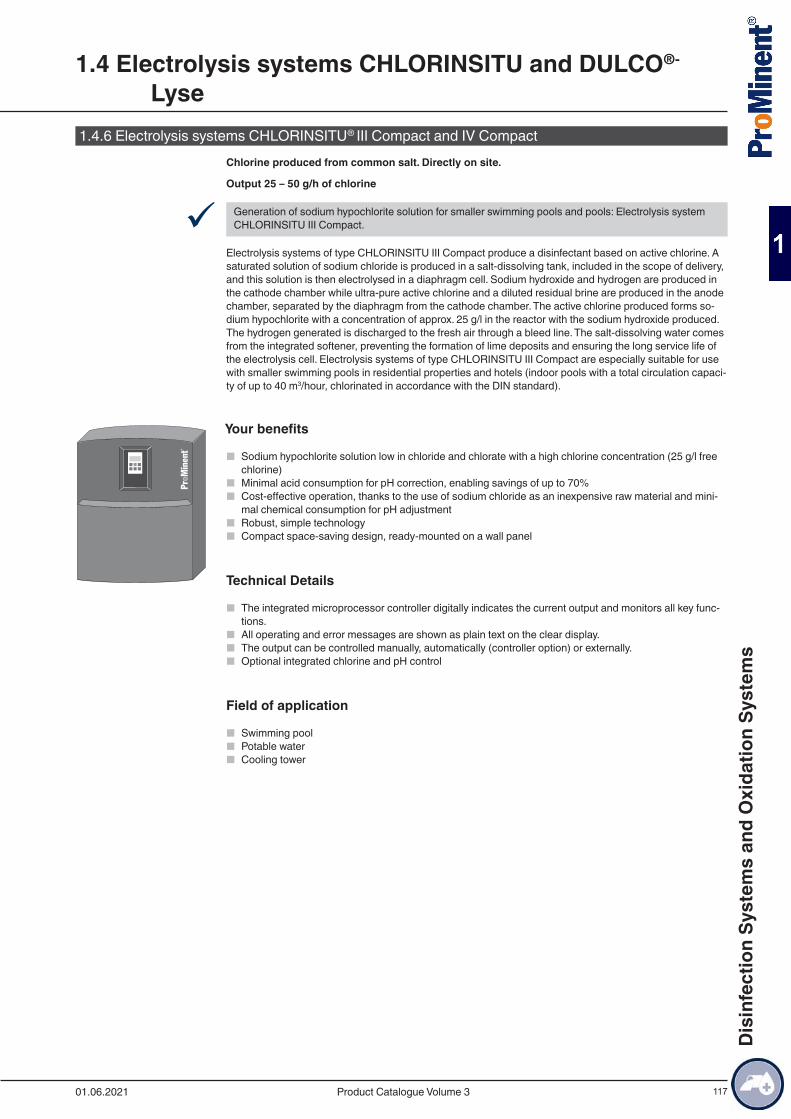
117
1.4.6 Electrolysis systems CHLORINSITU® III Compact and IV CompactChlorine produced from common salt. Directly on site.
Output 25 – 50 g/h of chlorine
9 Generation of sodium hypochlorite solution for smaller swimming pools and pools: Electrolysis system CHLORINSITU III Compact.
Electrolysis systems of type CHLORINSITU III Compact produce a disinfectant based on active chlorine. A saturated solution of sodium chloride is produced in a salt-dissolving tank, included in the scope of delivery, and this solution is then electrolysed in a diaphragm cell. Sodium hydroxide and hydrogen are produced in the cathode chamber while ultra-pure active chlorine and a diluted residual brine are produced in the anode chamber, separated by the diaphragm from the cathode chamber. The active chlorine produced forms so-dium hypochlorite with a concentration of approx. 25 g/l in the reactor with the sodium hydroxide produced. The hydrogen generated is discharged to the fresh air through a bleed line. The salt-dissolving water comes from the integrated softener, preventing the formation of lime deposits and ensuring the long service life of the electrolysis cell. Electrolysis systems of type CHLORINSITU III Compact are especially suitable for use with smaller swimming pools in residential properties and hotels (indoor pools with a total circulation capaci-ty of up to 40 m3/hour, chlorinated in accordance with the DIN standard).
Your benefits
■ Sodium hypochlorite solution low in chloride and chlorate with a high chlorine concentration (25 g/l free chlorine)
■ Minimal acid consumption for pH correction, enabling savings of up to 70% ■ Cost-effective operation, thanks to the use of sodium chloride as an inexpensive raw material and mini-
mal chemical consumption for pH adjustment ■ Robust, simple technology ■ Compact space-saving design, ready-mounted on a wall panel
Technical Details
■ The integrated microprocessor controller digitally indicates the current output and monitors all key func-tions.
■ All operating and error messages are shown as plain text on the clear display. ■ The output can be controlled manually, automatically (controller option) or externally. ■ Optional integrated chlorine and pH control
Field of application
■ Swimming pool ■ Potable water ■ Cooling tower
1.4 Electrolysis systems CHLORINSITU and DULCO®-
Lyse
01.06.2021 Product Catalogue Volume 3
Dis
infe
ctio
n Sy
stem
s an
d O
xida
tion
Syst
ems
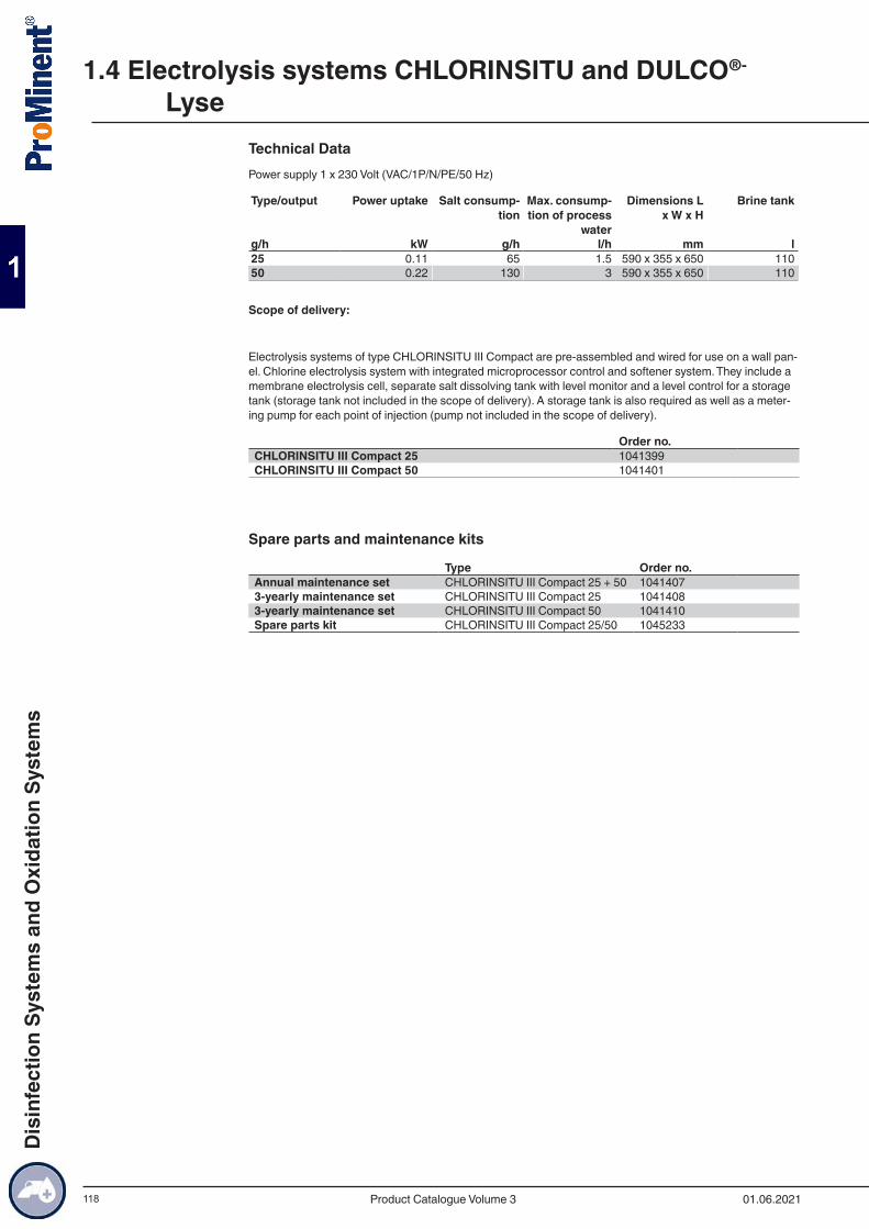
118
Technical DataPower supply 1 x 230 Volt (VAC/1P/N/PE/50 Hz)
Type/output Power uptake Salt consump-tion
Max. consump-tion of process
water
Dimensions L x W x H
Brine tank
g/h kW g/h l/h mm l25 0.11 65 1.5 590 x 355 x 650 11050 0.22 130 3 590 x 355 x 650 110
Scope of delivery:
Electrolysis systems of type CHLORINSITU III Compact are pre-assembled and wired for use on a wall pan-el. Chlorine electrolysis system with integrated microprocessor control and softener system. They include a membrane electrolysis cell, separate salt dissolving tank with level monitor and a level control for a storage tank (storage tank not included in the scope of delivery). A storage tank is also required as well as a meter-ing pump for each point of injection (pump not included in the scope of delivery).
Order no.CHLORINSITU III Compact 25 1041399CHLORINSITU III Compact 50 1041401
Spare parts and maintenance kits
Type Order no.Annual maintenance set CHLORINSITU III Compact 25 + 50 10414073-yearly maintenance set CHLORINSITU III Compact 25 10414083-yearly maintenance set CHLORINSITU III Compact 50 1041410Spare parts kit CHLORINSITU III Compact 25/50 1045233
1.4 Electrolysis systems CHLORINSITU and DULCO®-
Lyse
01.06.2021Product Catalogue Volume 3
Dis
infe
ctio
n Sy
stem
s an
d O
xida
tion
Syst
ems
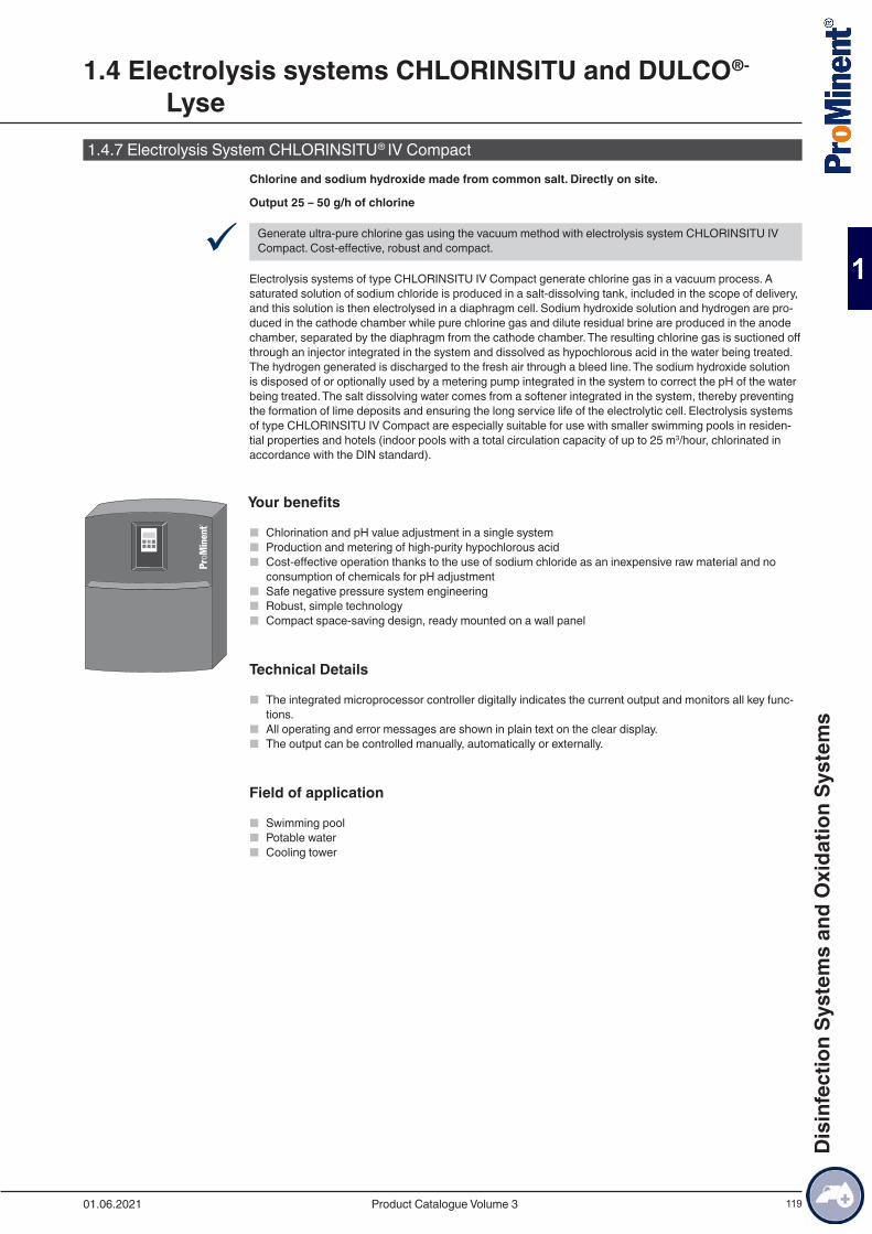
119
1.4.7 Electrolysis System CHLORINSITU® IV CompactChlorine and sodium hydroxide made from common salt. Directly on site.
Output 25 – 50 g/h of chlorine
9 Generate ultra-pure chlorine gas using the vacuum method with electrolysis system CHLORINSITU IV Compact. Cost-effective, robust and compact.
Electrolysis systems of type CHLORINSITU IV Compact generate chlorine gas in a vacuum process. A saturated solution of sodium chloride is produced in a salt-dissolving tank, included in the scope of delivery, and this solution is then electrolysed in a diaphragm cell. Sodium hydroxide solution and hydrogen are pro-duced in the cathode chamber while pure chlorine gas and dilute residual brine are produced in the anode chamber, separated by the diaphragm from the cathode chamber. The resulting chlorine gas is suctioned off through an injector integrated in the system and dissolved as hypochlorous acid in the water being treated. The hydrogen generated is discharged to the fresh air through a bleed line. The sodium hydroxide solution is disposed of or optionally used by a metering pump integrated in the system to correct the pH of the water being treated. The salt dissolving water comes from a softener integrated in the system, thereby preventing the formation of lime deposits and ensuring the long service life of the electrolytic cell. Electrolysis systems of type CHLORINSITU IV Compact are especially suitable for use with smaller swimming pools in residen-tial properties and hotels (indoor pools with a total circulation capacity of up to 25 m3/hour, chlorinated in accordance with the DIN standard).
Your benefits
■ Chlorination and pH value adjustment in a single system ■ Production and metering of high-purity hypochlorous acid ■ Cost-effective operation thanks to the use of sodium chloride as an inexpensive raw material and no
consumption of chemicals for pH adjustment ■ Safe negative pressure system engineering ■ Robust, simple technology ■ Compact space-saving design, ready mounted on a wall panel
Technical Details
■ The integrated microprocessor controller digitally indicates the current output and monitors all key func-tions.
■ All operating and error messages are shown in plain text on the clear display. ■ The output can be controlled manually, automatically or externally.
Field of application
■ Swimming pool ■ Potable water ■ Cooling tower
1.4 Electrolysis systems CHLORINSITU and DULCO®-
Lyse
01.06.2021 Product Catalogue Volume 3
Dis
infe
ctio
n Sy
stem
s an
d O
xida
tion
Syst
ems
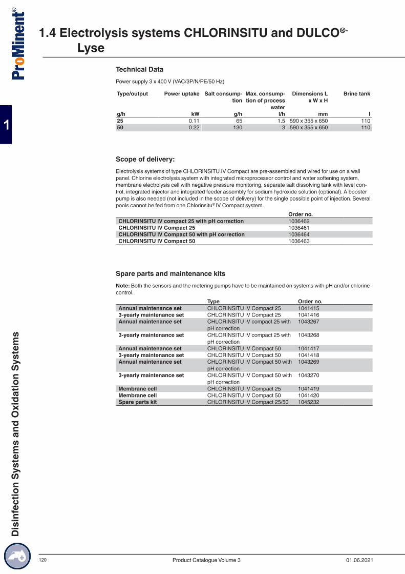
120
Technical DataPower supply 3 x 400 V (VAC/3P/N/PE/50 Hz)
Type/output Power uptake Salt consump-tion
Max. consump-tion of process
water
Dimensions L x W x H
Brine tank
g/h kW g/h l/h mm l25 0.11 65 1.5 590 x 355 x 650 11050 0.22 130 3 590 x 355 x 650 110
Scope of delivery:Electrolysis systems of type CHLORINSITU IV Compact are pre-assembled and wired for use on a wall panel. Chlorine electrolysis system with integrated microprocessor control and water softening system, membrane electrolysis cell with negative pressure monitoring, separate salt dissolving tank with level con-trol, integrated injector and integrated feeder assembly for sodium hydroxide solution (optional). A booster pump is also needed (not included in the scope of delivery) for the single possible point of injection. Several pools cannot be fed from one Chlorinsitu® IV Compact system.
Order no.CHLORINSITU IV compact 25 with pH correction 1036462CHLORINSITU IV Compact 25 1036461CHLORINSITU IV Compact 50 with pH correction 1036464CHLORINSITU IV Compact 50 1036463
Spare parts and maintenance kitsNote: Both the sensors and the metering pumps have to be maintained on systems with pH and/or chlorine control.
Type Order no.Annual maintenance set CHLORINSITU IV Compact 25 10414153-yearly maintenance set CHLORINSITU IV Compact 25 1041416Annual maintenance set CHLORINSITU IV compact 25 with
pH correction1043267
3-yearly maintenance set CHLORINSITU IV compact 25 with pH correction
1043268
Annual maintenance set CHLORINSITU IV Compact 50 10414173-yearly maintenance set CHLORINSITU IV Compact 50 1041418Annual maintenance set CHLORINSITU IV Compact 50 with
pH correction1043269
3-yearly maintenance set CHLORINSITU IV Compact 50 with pH correction
1043270
Membrane cell CHLORINSITU IV Compact 25 1041419Membrane cell CHLORINSITU IV Compact 50 1041420Spare parts kit CHLORINSITU IV Compact 25/50 1045232
1.4 Electrolysis systems CHLORINSITU and DULCO®-
Lyse
01.06.2021Product Catalogue Volume 3
Dis
infe
ctio
n Sy
stem
s an
d O
xida
tion
Syst
ems
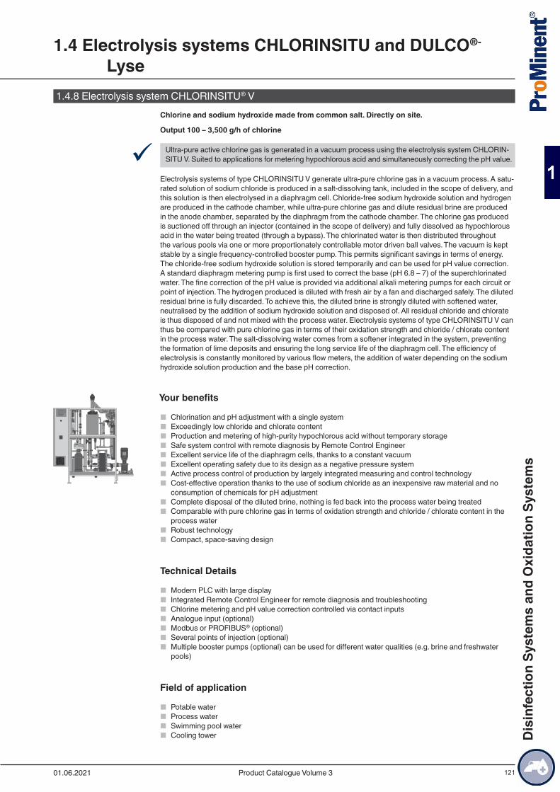
121
1.4.8 Electrolysis system CHLORINSITU® VChlorine and sodium hydroxide made from common salt. Directly on site.
Output 100 – 3,500 g/h of chlorine
9 Ultra-pure active chlorine gas is generated in a vacuum process using the electrolysis system CHLORIN-SITU V. Suited to applications for metering hypochlorous acid and simultaneously correcting the pH value.
Electrolysis systems of type CHLORINSITU V generate ultra-pure chlorine gas in a vacuum process. A satu-rated solution of sodium chloride is produced in a salt-dissolving tank, included in the scope of delivery, and this solution is then electrolysed in a diaphragm cell. Chloride-free sodium hydroxide solution and hydrogen are produced in the cathode chamber, while ultra-pure chlorine gas and dilute residual brine are produced in the anode chamber, separated by the diaphragm from the cathode chamber. The chlorine gas produced is suctioned off through an injector (contained in the scope of delivery) and fully dissolved as hypochlorous acid in the water being treated (through a bypass). The chlorinated water is then distributed throughout the various pools via one or more proportionately controllable motor driven ball valves. The vacuum is kept stable by a single frequency-controlled booster pump. This permits significant savings in terms of energy. The chloride-free sodium hydroxide solution is stored temporarily and can be used for pH value correction. A standard diaphragm metering pump is first used to correct the base (pH 6.8 – 7) of the superchlorinated water. The fine correction of the pH value is provided via additional alkali metering pumps for each circuit or point of injection. The hydrogen produced is diluted with fresh air by a fan and discharged safely. The diluted residual brine is fully discarded. To achieve this, the diluted brine is strongly diluted with softened water, neutralised by the addition of sodium hydroxide solution and disposed of. All residual chloride and chlorate is thus disposed of and not mixed with the process water. Electrolysis systems of type CHLORINSITU V can thus be compared with pure chlorine gas in terms of their oxidation strength and chloride / chlorate content in the process water. The salt-dissolving water comes from a softener integrated in the system, preventing the formation of lime deposits and ensuring the long service life of the diaphragm cell. The efficiency of electrolysis is constantly monitored by various flow meters, the addition of water depending on the sodium hydroxide solution production and the base pH correction.
Your benefits
■ Chlorination and pH adjustment with a single system ■ Exceedingly low chloride and chlorate content ■ Production and metering of high-purity hypochlorous acid without temporary storage ■ Safe system control with remote diagnosis by Remote Control Engineer ■ Excellent service life of the diaphragm cells, thanks to a constant vacuum ■ Excellent operating safety due to its design as a negative pressure system ■ Active process control of production by largely integrated measuring and control technology ■ Cost-effective operation thanks to the use of sodium chloride as an inexpensive raw material and no
consumption of chemicals for pH adjustment ■ Complete disposal of the diluted brine, nothing is fed back into the process water being treated ■ Comparable with pure chlorine gas in terms of oxidation strength and chloride / chlorate content in the
process water ■ Robust technology ■ Compact, space-saving design
Technical Details
■ Modern PLC with large display ■ Integrated Remote Control Engineer for remote diagnosis and troubleshooting ■ Chlorine metering and pH value correction controlled via contact inputs ■ Analogue input (optional) ■ Modbus or PROFIBUS® (optional) ■ Several points of injection (optional) ■ Multiple booster pumps (optional) can be used for different water qualities (e.g. brine and freshwater
pools)
Field of application
■ Potable water ■ Process water ■ Swimming pool water ■ Cooling tower
1.4 Electrolysis systems CHLORINSITU and DULCO®-
Lyse
01.06.2021 Product Catalogue Volume 3
Dis
infe
ctio
n Sy
stem
s an
d O
xida
tion
Syst
ems
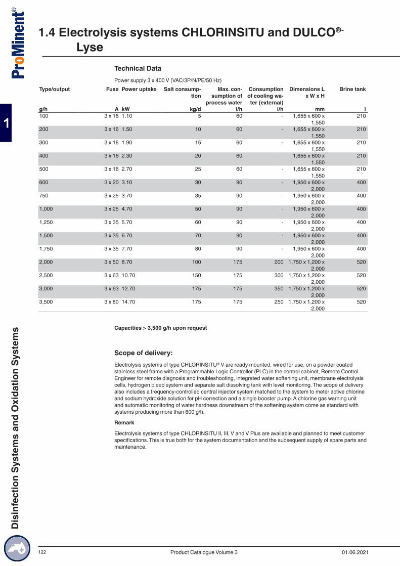
122
Technical DataPower supply 3 x 400 V (VAC/3P/N/PE/50 Hz)
Type/output Fuse Power uptake Salt consump-tion
Max. con-sumption of
process water
Consumption of cooling wa-ter (external)
Dimensions L x W x H
Brine tank
g/h A kW kg/d l/h l/h mm l100 3 x 16 1.10 5 60 - 1,655 x 600 x
1,550210
200 3 x 16 1.50 10 60 - 1,655 x 600 x 1,550
210
300 3 x 16 1.90 15 60 - 1,655 x 600 x 1,550
210
400 3 x 16 2.30 20 60 - 1,655 x 600 x 1,550
210
500 3 x 16 2.70 25 60 - 1,655 x 600 x 1,550
210
600 3 x 20 3.10 30 90 - 1,950 x 600 x 2,000
400
750 3 x 25 3.70 35 90 - 1,950 x 600 x 2,000
400
1,000 3 x 25 4.70 50 90 - 1,950 x 600 x 2,000
400
1,250 3 x 35 5.70 60 90 - 1,950 x 600 x 2,000
400
1,500 3 x 35 6.70 70 90 - 1,950 x 600 x 2,000
400
1,750 3 x 35 7.70 80 90 - 1,950 x 600 x 2,000
400
2,000 3 x 50 8.70 100 175 200 1,750 x 1,200 x 2,000
520
2,500 3 x 63 10.70 150 175 300 1,750 x 1,200 x 2,000
520
3,000 3 x 63 12.70 175 175 350 1,750 x 1,200 x 2,000
520
3,500 3 x 80 14.70 175 175 250 1,750 x 1,200 x 2,000
520
Capacities > 3,500 g/h upon request
Scope of delivery:Electrolysis systems of type CHLORINSITU® V are ready mounted, wired for use, on a powder coated stainless steel frame with a Programmable Logic Controller (PLC) in the control cabinet, Remote Control Engineer for remote diagnosis and troubleshooting, integrated water softening unit, membrane electrolysis cells, hydrogen bleed system and separate salt dissolving tank with level monitoring. The scope of delivery also includes a frequency-controlled central injector system matched to the system to meter active chlorine and sodium hydroxide solution for pH correction and a single booster pump. A chlorine gas warning unit and automatic monitoring of water hardness downstream of the softening system come as standard with systems producing more than 600 g/h.
Remark
Electrolysis systems of type CHLORINSITU II, III, V and V Plus are available and planned to meet customer specifications. This is true both for the system documentation and the subsequent supply of spare parts and maintenance.
1.4 Electrolysis systems CHLORINSITU and DULCO®-
Lyse
01.06.2021Product Catalogue Volume 3
Dis
infe
ctio
n Sy
stem
s an
d O
xida
tion
Syst
ems

123
1.4.9 Electrolysis system CHLORINSITU® V PlusChlorine and sodium hydroxide made from common salt. Directly on site.
Output 100 – 3,500 g/h of chlorine
9 Ultra-pure active chlorine gas is generated in a vacuum process using the electrolysis system CHLORIN-SITU V. Suited to applications for metering hypochlorous acid and simultaneously correcting the pH value.
Electrolysis systems of type CHLORINSITU V Plus generate ultra-pure chlorine gas combined with a sodium hypochlorite solution in a vacuum process. A saturated solution of sodium chloride is produced in a salt-dissolving tank, included in the scope of delivery, and this solution is then electrolysed in a diaphragm cell. Chloride-free sodium hydroxide solution and hydrogen are produced in the cathode chamber, while ultra-pure chlorine gas and residual brine are produced in the anode chamber, separated by a diaphragm from the cathode chamber. The resulting ultra-pure chlorine gas is further processed in two ways. Firstly, it is suctioned off through an injector (included in the scope of delivery) and fully dissolved as hypochlorous acid in the water being treated (through a bypass). The superchlorinated water is then distributed throughout the various pools via one or more proportionately controllable motor driven ball valves. The vacuum is kept sta-ble by a single frequency-controlled booster pump. This permits significant savings in terms of energy. If the complete production output is not needed, excess chlorine gas can be combined with the sodium hydroxide solution produced and then temporarily stored as sodium hypochlorite (PLUS system). The system thus does not have to be sized based on the maximum chlorine gas demand rather on the average daily demand. Peaks in demand are met by the additional metering of sodium hypochlorite from the temporary reservoir, which, as with hypochlorous acid, is fed through a central injector system.
The chloride-free sodium hydroxide solution is stored temporarily and can be used for pH value correction. First the base pH (pH 6.8 – 7) of the superchlorinated water is corrected by a standard diaphragm metering pump or through the addition of sodium hypochlorite. The fine correction of the pH value is provided via additional alkali metering pumps for each circuit or point of injection. They are connected directly to the sys-tem’s control through an external pH value controller. The hydrogen produced is seriously diluted with fresh air by a fan and discharged safely. The residual brine is fully discarded. To achieve this, the residual brine is strongly diluted with softened water, neutralised by the addition of sodium hydroxide solution and disposed of in the sewer. Any residual chloride and chlorate is thereby disposed of and not mixed with the process water. Electrolysis systems of type CHLORINSITU V Plus can therefore be compared with pure chlorine gas in terms of their oxidation strength and chloride / chlorate content in the process water. The salt-dissolving water comes from a softener integrated in the system, preventing the formation of lime deposits and ensur-ing the long service life of the diaphragm cell. The efficiency of the electrolysis is constantly monitored by various flow meters, the addition of water depending on the sodium hydroxide solution production and the base pH correction.
Your benefits
■ Chlorination and pH adjustment with a single system ■ Exceedingly low chloride and chlorate content ■ Production and metering of high-purity hypochlorous acid without temporary storage ■ Safe system control with remote diagnosis by Remote Control Engineer ■ Excellent service life of the diaphragm cells, thanks to a constant vacuum ■ Excellent operating safety due to its design as a negative pressure system ■ Active process control of production by largely integrated measuring and control technology ■ Cost-effective operation thanks to the use of sodium chloride as an inexpensive raw material and no
consumption of chemicals for pH adjustment ■ Complete disposal of the diluted brine, nothing is fed back into the process water being treated ■ Comparable with pure chlorine gas in terms of oxidation strength and chloride / chlorate content in the
process water ■ Robust technology ■ Compact, space-saving design
Technical Details
■ Modern PLC with large display ■ Integrated Remote Control Engineer for remote diagnosis and troubleshooting ■ Chlorine metering and pH value correction controlled via contact inputs ■ Analogue input (optional) ■ Modbus or PROFIBUS® (optional) ■ Several points of injection (optional) ■ Multiple booster pumps (optional) can be used for different water qualities (e.g. brine and freshwater
pools)
1.4 Electrolysis systems CHLORINSITU and DULCO®-
Lyse
01.06.2021 Product Catalogue Volume 3
Dis
infe
ctio
n Sy
stem
s an
d O
xida
tion
Syst
ems
124
Field of application
■ Potable water ■ Process water ■ Swimming pool water ■ Cooling tower
1.4 Electrolysis systems CHLORINSITU and DULCO®-
Lyse
01.06.2021Product Catalogue Volume 3
Dis
infe
ctio
n Sy
stem
s an
d O
xida
tion
Syst
ems
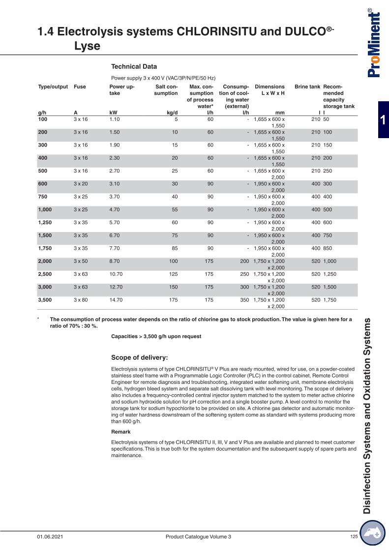
125
Technical DataPower supply 3 x 400 V (VAC/3P/N/PE/50 Hz)
Type/output Fuse Power up-take
Salt con-sumption
Max. con-sumption
of process water*
Consump-tion of cool-
ing water (external)
Dimensions L x W x H
Brine tank Recom-mended capacity storage tank
g/h A kW kg/d l/h l/h mm l l100 3 x 16 1.10 5 60 - 1,655 x 600 x
1,550210 50
200 3 x 16 1.50 10 60 - 1,655 x 600 x 1,550
210 100
300 3 x 16 1.90 15 60 - 1,655 x 600 x 1,550
210 150
400 3 x 16 2.30 20 60 - 1,655 x 600 x 1,550
210 200
500 3 x 16 2.70 25 60 - 1,655 x 600 x 2,000
210 250
600 3 x 20 3.10 30 90 - 1,950 x 600 x 2,000
400 300
750 3 x 25 3.70 40 90 - 1,950 x 600 x 2,000
400 400
1,000 3 x 25 4.70 55 90 - 1,950 x 600 x 2,000
400 500
1,250 3 x 35 5.70 60 90 - 1,950 x 600 x 2,000
400 600
1,500 3 x 35 6.70 75 90 - 1,950 x 600 x 2,000
400 750
1,750 3 x 35 7.70 85 90 - 1,950 x 600 x 2,000
400 850
2,000 3 x 50 8.70 100 175 200 1,750 x 1,200 x 2,000
520 1,000
2,500 3 x 63 10.70 125 175 250 1,750 x 1,200 x 2,000
520 1,250
3,000 3 x 63 12.70 150 175 300 1,750 x 1,200 x 2,000
520 1,500
3,500 3 x 80 14.70 175 175 350 1,750 x 1,200 x 2,000
520 1,750
* The consumption of process water depends on the ratio of chlorine gas to stock production. The value is given here for a ratio of 70% : 30 %.
Capacities > 3,500 g/h upon request
Scope of delivery:Electrolysis systems of type CHLORINSITU® V Plus are ready mounted, wired for use, on a powder-coated stainless steel frame with a Programmable Logic Controller (PLC) in the control cabinet, Remote Control Engineer for remote diagnosis and troubleshooting, integrated water softening unit, membrane electrolysis cells, hydrogen bleed system and separate salt dissolving tank with level monitoring. The scope of delivery also includes a frequency-controlled central injector system matched to the system to meter active chlorine and sodium hydroxide solution for pH correction and a single booster pump. A level control to monitor the storage tank for sodium hypochlorite to be provided on site. A chlorine gas detector and automatic monitor-ing of water hardness downstream of the softening system come as standard with systems producing more than 600 g/h.
Remark
Electrolysis systems of type CHLORINSITU II, III, V and V Plus are available and planned to meet customer specifications. This is true both for the system documentation and the subsequent supply of spare parts and maintenance.
1.4 Electrolysis systems CHLORINSITU and DULCO®-
Lyse
01.06.2021 Product Catalogue Volume 3
Dis
infe
ctio
n Sy
stem
s an
d O
xida
tion
Syst
ems
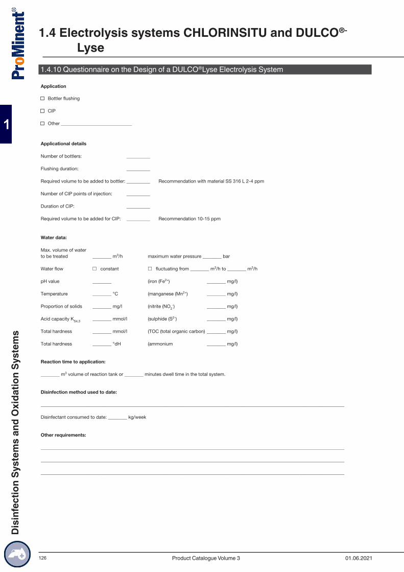
126
1.4.10 Questionnaire on the Design of a DULCO®Lyse Electrolysis System
1.4 Electrolysis systems CHLORINSITU and DULCO®-
Lyse
01.06.2021Product Catalogue Volume 3
Dis
infe
ctio
n Sy
stem
s an
d O
xida
tion
Syst
ems
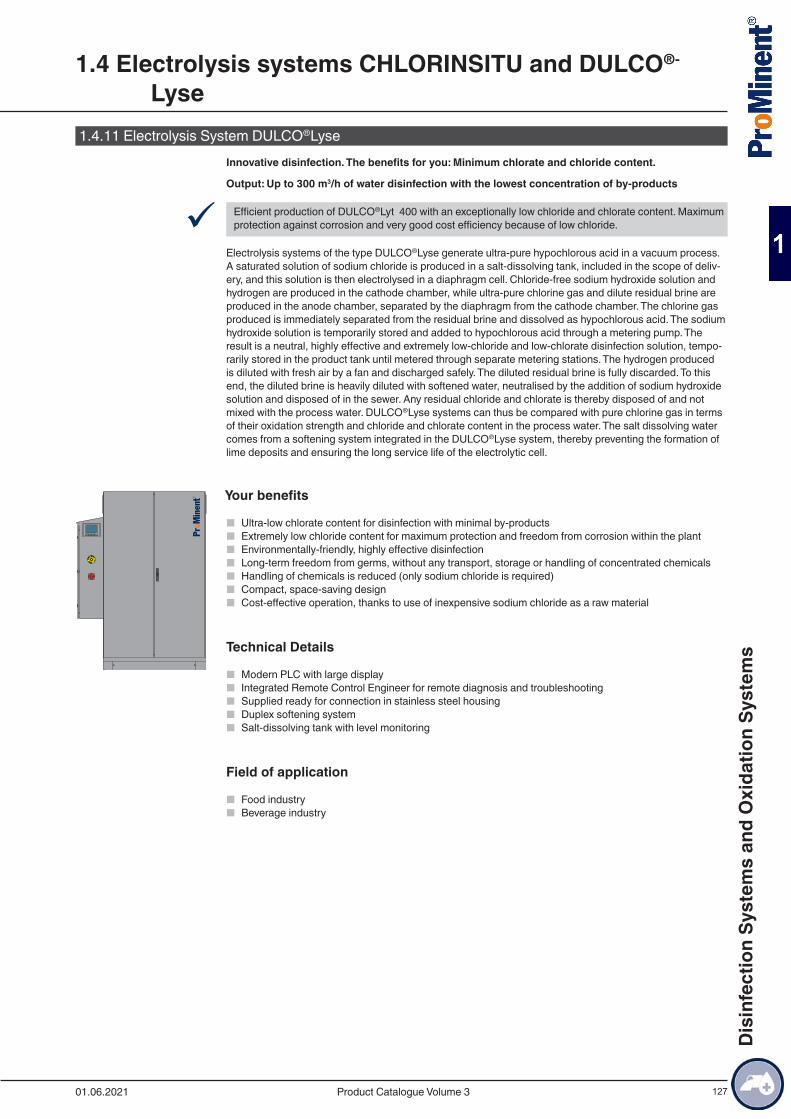
127
1.4.11 Electrolysis System DULCO®Lyse Innovative disinfection. The benefits for you: Minimum chlorate and chloride content.
Output: Up to 300 m3/h of water disinfection with the lowest concentration of by-products
9 Efficient production of DULCO®Lyt 400 with an exceptionally low chloride and chlorate content. Maximum protection against corrosion and very good cost efficiency because of low chloride.
Electrolysis systems of the type DULCO®Lyse generate ultra-pure hypochlorous acid in a vacuum process. A saturated solution of sodium chloride is produced in a salt-dissolving tank, included in the scope of deliv-ery, and this solution is then electrolysed in a diaphragm cell. Chloride-free sodium hydroxide solution and hydrogen are produced in the cathode chamber, while ultra-pure chlorine gas and dilute residual brine are produced in the anode chamber, separated by the diaphragm from the cathode chamber. The chlorine gas produced is immediately separated from the residual brine and dissolved as hypochlorous acid. The sodium hydroxide solution is temporarily stored and added to hypochlorous acid through a metering pump. The result is a neutral, highly effective and extremely low-chloride and low-chlorate disinfection solution, tempo-rarily stored in the product tank until metered through separate metering stations. The hydrogen produced is diluted with fresh air by a fan and discharged safely. The diluted residual brine is fully discarded. To this end, the diluted brine is heavily diluted with softened water, neutralised by the addition of sodium hydroxide solution and disposed of in the sewer. Any residual chloride and chlorate is thereby disposed of and not mixed with the process water. DULCO®Lyse systems can thus be compared with pure chlorine gas in terms of their oxidation strength and chloride and chlorate content in the process water. The salt dissolving water comes from a softening system integrated in the DULCO®Lyse system, thereby preventing the formation of lime deposits and ensuring the long service life of the electrolytic cell.
Your benefits
■ Ultra-low chlorate content for disinfection with minimal by-products ■ Extremely low chloride content for maximum protection and freedom from corrosion within the plant ■ Environmentally-friendly, highly effective disinfection ■ Long-term freedom from germs, without any transport, storage or handling of concentrated chemicals ■ Handling of chemicals is reduced (only sodium chloride is required) ■ Compact, space-saving design ■ Cost-effective operation, thanks to use of inexpensive sodium chloride as a raw material
Technical Details
■ Modern PLC with large display ■ Integrated Remote Control Engineer for remote diagnosis and troubleshooting ■ Supplied ready for connection in stainless steel housing ■ Duplex softening system ■ Salt-dissolving tank with level monitoring
Field of application
■ Food industry ■ Beverage industry
1.4 Electrolysis systems CHLORINSITU and DULCO®-
Lyse
01.06.2021 Product Catalogue Volume 3
Dis
infe
ctio
n Sy
stem
s an
d O
xida
tion
Syst
ems

128
Technical DataPower supply: 1 x 230 Volt (V AC/1P/N/PE/50 Hz)
Dimensions (H x W x D): 2,100 x 1,250 x 610 mm
Product designation Type/output DULCO®Lyt production at 400 ppm
Power uptake
Salt solu-tion tank volume
Cabinet Order no.
g/h l/h kW l DULCO®Lyse 100 100 250 1.10 210 stainless
steel cabinet1041424
DULCO®Lyse 100 100 250 1.10 210 open cabinet 1062093DULCO®Lyse 200 200 500 1.50 210 stainless
steel cabinet1043987
DULCO®Lyse 200 200 500 1.50 210 open cabinet 1062104DULCO®Lyse 300 300 750 1.90 210 stainless
steel cabinet1043988
DULCO®Lyse 300 300 750 1.90 210 open cabinet 1062135
Scope of delivery:DULCO®Lyse electrolysis systems are fitted ready for use in a sealed stainless steel or open cabinet
■ PLC (Programmable Logic Controller) in the attached control cabinet ■ Duplex water softening system ■ Salt-dissolving tank with level monitoring ■ Ultrasound level probe for the DULCO®Lyt product tank ■ Piping between the salt-dissolving storage tank and DULCO®Lyse system ■ Hardness control measuring equipment ■ pH4 + pH7 buffer solution
Not included in the scope of delivery:
■ DULCO®Lyt product tank ■ DULCO®Lyt metering station
Spare parts and maintenance kitsType Order no.
Spare parts kit up to manufac-turing year 2015
DULCO®Lyse 100 – 300 1044366
Spare parts kit from manufac-turing year 2015 onwards
DULCO®Lyse 100 – 300 1079469
Annual maintenance set DULCO®Lyse 100 – 300 10414273-yearly maintenance set DULCO®Lyse 100 – 300 1041430
1.4 Electrolysis systems CHLORINSITU and DULCO®-
Lyse
01.06.2021Product Catalogue Volume 3
Dis
infe
ctio
n Sy
stem
s an
d O
xida
tion
Syst
ems
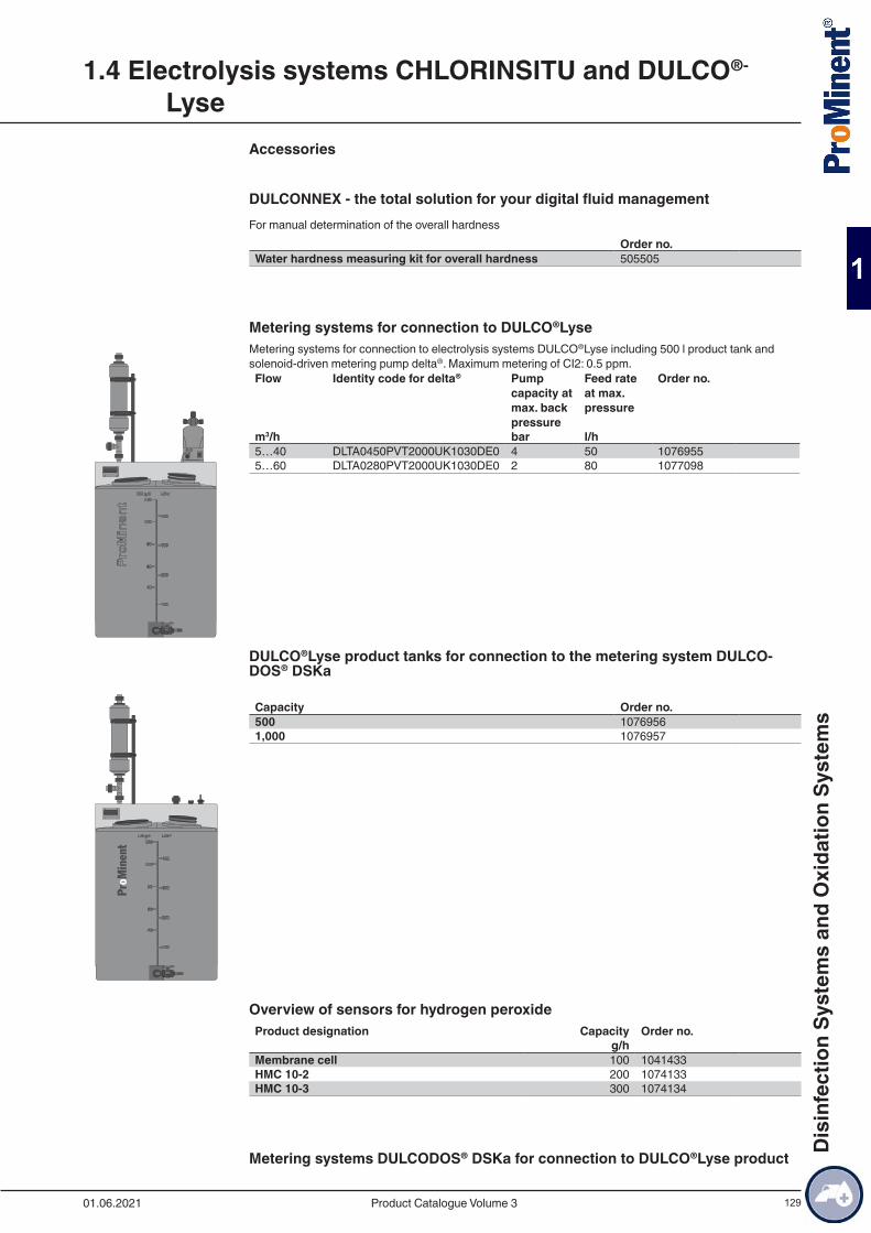
129
Accessories
DULCONNEX - the total solution for your digital fluid managementFor manual determination of the overall hardness
Order no.Water hardness measuring kit for overall hardness 505505
Metering systems for connection to DULCO®LyseMetering systems for connection to electrolysis systems DULCO®Lyse including 500 l product tank and solenoid-driven metering pump delta®. Maximum metering of CI2: 0.5 ppm.Flow Identity code for delta® Pump
capacity at max. back pressure
Feed rate at max. pressure
Order no.
m3/h bar l/h 5…40 DLTA0450PVT2000UK1030DE0 4 50 10769555…60 DLTA0280PVT2000UK1030DE0 2 80 1077098
DULCO®Lyse product tanks for connection to the metering system DULCO-DOS® DSKa Capacity Order no.500 10769561,000 1076957
Overview of sensors for hydrogen peroxideProduct designation Capacity Order no. g/h Membrane cell 100 1041433HMC 10-2 200 1074133HMC 10-3 300 1074134
Metering systems DULCODOS® DSKa for connection to DULCO®Lyse product
1.4 Electrolysis systems CHLORINSITU and DULCO®-
Lyse
01.06.2021 Product Catalogue Volume 3
Dis
infe
ctio
n Sy
stem
s an
d O
xida
tion
Syst
ems
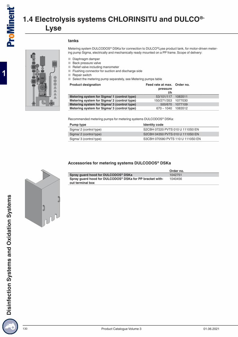
130
tanks
Metering system DULCODOS® DSKa for connection to DULCO®Lyse product tank, for motor-driven meter-ing pump Sigma, electrically and mechanically ready mounted on a PP frame. Scope of delivery:
■ Diaphragm damper ■ Back pressure valve ■ Relief valve including manometer ■ Flushing connector for suction and discharge side ■ Repair switch ■ Select the metering pump separately, see Metering pumps table
Product designation Feed rate at max. pressure
Order no.
l/h Metering system for Sigma/ 1 (control type) 53/101/117 1083511Metering system for Sigma/ 2 (control type) 150/271/353 1077030Metering system for Sigma/ 3 (control type) 500/670 1077109Metering system for Sigma/ 3 (control type) 670 – 1040 1083512
Recommended metering pumps for metering systems DULCODOS® DSKa:Pump type Identity codeSigma/ 2 (control type) S2CBH 07220 PVTS 010 U 1110S0 ENSigma/ 2 (control type) S2CBH 04350 PVTS 010 U 1110S0 ENSigma/ 3 (control type) S3CBH 070580 PVTS 110 U 1110S0 EN
Accessories for metering systems DULCODOS® DSKa
Order no.Spray guard hood for DULCODOS® DSKa 1042751Spray guard hood for DULCODOS® DSKa for PP bracket with-out terminal box
1040456
1.4 Electrolysis systems CHLORINSITU and DULCO®-
Lyse
01.06.2021Product Catalogue Volume 3
Dis
infe
ctio
n Sy
stem
s an
d O
xida
tion
Syst
ems
131
1.5.1 General Information on Chlorine Gas Metering SystemsChlorine gas metering systems are used in water treatment for disinfection and oxidation. They prevent and/or reduce the growth of micro-organisms.
The safety of users is the priority. This is essentially guaranteed by vacuum operation directly from the chlorine gas tank and downstream of the evaporator. This ensures that the escape of chlorine gas can be prevented even in the event of a ruptured pipe.
All the components are perfectly coordinated to each other and ensure seamless operation. With higher demand, several storage tanks can be combined using manifolds. Uninterrupted chlorine gas supply can be ensured by the use of an automatic vacuum switch.
Chlorine gas stands out on account of its high bacteria destruction speed coupled with low operating costs. Due to the high level of reactivity, sensible handling and compliance with common safety regulations (e.g. DIN 19606, BGV D5 / DGUV-V 50, BGR/GUV-R 108 and other regional regulations) is imperative.
No by-products are metered by the use of pure chlorine gas and thus the water quality is maintained. Fur-thermore, chlorine gas can be stored as required without forming decomposition products.
Chlorine is a pungent smelling yellow/green gas in its normal state. The density is ~3.2 kg/m3, thus chlorine gas is heavier than air. Chlorine is supplied in liquid form and changes to its gaseous state during extraction caused by reduced pressure. The vacuum generated by an injector draws the chlorine gas by suction to the point of injection. The chlorine gas is dissolved in water and produces hypochlorous acid responsible for disinfection.
Make sure that only a technical expert carries out commissioning, maintenance and repair. Com-pliance with national and regional regulations is mandatory.
Chlorine Gas Metering Systems DULCO®VaqIn the metering system DULCO®Vaq, chlorine gas is safely handled under a vacuum. The negative pressure generated in the injector opens the vacuum dosing regulator fitted on the chlorine gas tank and the chlorine gas enters the water to be treated. Adjustment valves control the metering volume and flow meters precisely indicate the chlorine gas flow. A large number of individual configurations is provided for by the use of addi-tional components, such as motorised control valves, injectors or vacuum switch-overs.
ProMinent DULCO®Vaq components are used for large-scale chlorine gas systems for applications in industry and the treatment of large volumes of water. Additional components, such as evaporators, pressure reducing valves, pressure switch-overs, metering systems and corresponding room equipment.
ProMinent experts consider the latest safety requirements when designing systems for specific projects.
Perfect safety for operators and users with ProMinent chlorine gas metering systems DULCO®Vaq.
1.5 Chlorine Gas Metering Systems DULCO®Vaq
01.06.2021 Product Catalogue Volume 3
Dis
infe
ctio
n Sy
stem
s an
d O
xida
tion
Syst
ems
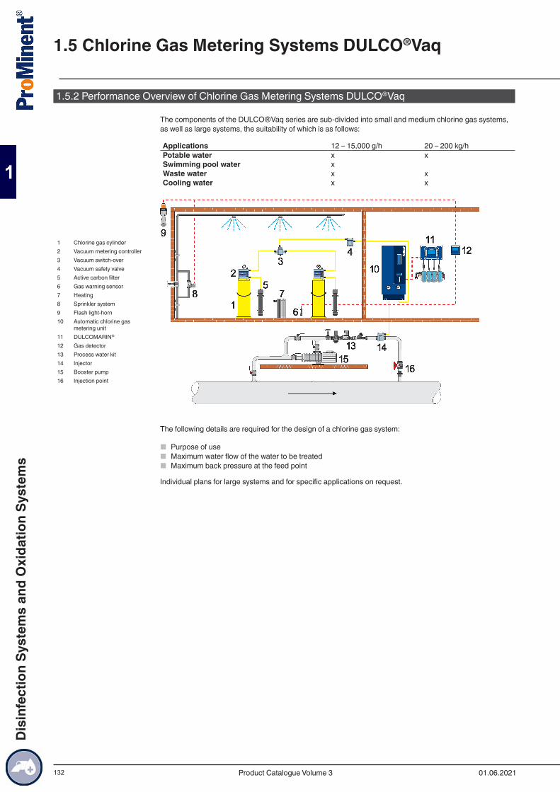
132
1.5.2 Performance Overview of Chlorine Gas Metering Systems DULCO®Vaq
The components of the DULCO®Vaq series are sub-divided into small and medium chlorine gas systems, as well as large systems, the suitability of which is as follows:
Applications 12 – 15,000 g/h 20 – 200 kg/hPotable water x xSwimming pool water x Waste water x xCooling water x x
1 Chlorine gas cylinder2 Vacuum metering controller3 Vacuum switch-over4 Vacuum safety valve5 Active carbon filter6 Gas warning sensor7 Heating8 Sprinkler system9 Flash light-horn10 Automatic chlorine gas
metering unit11 DULCOMARIN®
12 Gas detector13 Process water kit14 Injector15 Booster pump16 Injection point
The following details are required for the design of a chlorine gas system:
■ Purpose of use ■ Maximum water flow of the water to be treated ■ Maximum back pressure at the feed point
Individual plans for large systems and for specific applications on request.
1.5 Chlorine Gas Metering Systems DULCO®Vaq
01.06.2021Product Catalogue Volume 3
Dis
infe
ctio
n Sy
stem
s an
d O
xida
tion
Syst
ems

133
1.5.3 Questionnaire on the Design of a Chlorine Gas Metering System
Use of the chlorine gas system:For the disinfection of � Potable water
� Swimming pool water� Waste water� Cooling water� ___________
Water values:Max. water flow ____ m3/hWater flow � constant
� fluctuating from _______ m3/h to _____ __m3/hBack pressure in the main line ____ barpH value ____Temperature ____ °CSolids proportion ____ mg/lAcid capacity K S4,3 ____ mmol/lDistance from the vacuum controller to the injector ____ m
Type of metering: � manual� automatic � flow-proportional
� measured value-dependent� both
Required feed volume: ____ mg/l
Required concentration after chlorine gas metering: ____ mg/l
Design of the system:Number of points of injection ____Vacuum controller duty / standby � yes / � noChlorine gas unit duty / standby � yes / � noChlorine gas cylinders or drums ____ cylinder(s) ____ kg
____ drum(s) ____ kgBooster pump fitted � yes / � no
Other requirements:_____________________________________________________________________________________________________________________________________________________________________________________________________________________________________________________________________________________________________________________________________________________________________________________________________________________________________________________________________
1.5 Chlorine Gas Metering Systems DULCO®Vaq
01.06.2021 Product Catalogue Volume 3
Dis
infe
ctio
n Sy
stem
s an
d O
xida
tion
Syst
ems
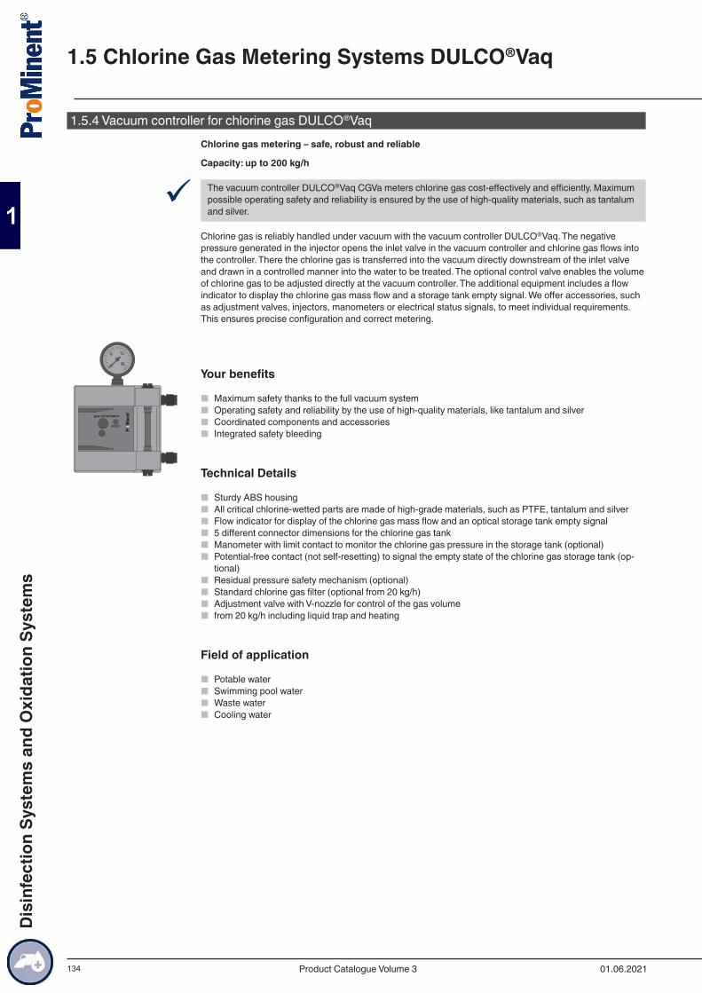
134
1.5.4 Vacuum controller for chlorine gas DULCO®VaqChlorine gas metering – safe, robust and reliable
Capacity: up to 200 kg/h
9 The vacuum controller DULCO®Vaq CGVa meters chlorine gas cost-effectively and efficiently. Maximum possible operating safety and reliability is ensured by the use of high-quality materials, such as tantalum and silver.
Chlorine gas is reliably handled under vacuum with the vacuum controller DULCO®Vaq. The negative pressure generated in the injector opens the inlet valve in the vacuum controller and chlorine gas flows into the controller. There the chlorine gas is transferred into the vacuum directly downstream of the inlet valve and drawn in a controlled manner into the water to be treated. The optional control valve enables the volume of chlorine gas to be adjusted directly at the vacuum controller. The additional equipment includes a flow indicator to display the chlorine gas mass flow and a storage tank empty signal. We offer accessories, such as adjustment valves, injectors, manometers or electrical status signals, to meet individual requirements. This ensures precise configuration and correct metering.
Your benefits
■ Maximum safety thanks to the full vacuum system ■ Operating safety and reliability by the use of high-quality materials, like tantalum and silver ■ Coordinated components and accessories ■ Integrated safety bleeding
Technical Details
■ Sturdy ABS housing ■ All critical chlorine-wetted parts are made of high-grade materials, such as PTFE, tantalum and silver ■ Flow indicator for display of the chlorine gas mass flow and an optical storage tank empty signal ■ 5 different connector dimensions for the chlorine gas tank ■ Manometer with limit contact to monitor the chlorine gas pressure in the storage tank (optional) ■ Potential-free contact (not self-resetting) to signal the empty state of the chlorine gas storage tank (op-
tional) ■ Residual pressure safety mechanism (optional) ■ Standard chlorine gas filter (optional from 20 kg/h) ■ Adjustment valve with V-nozzle for control of the gas volume ■ from 20 kg/h including liquid trap and heating
Field of application
■ Potable water ■ Swimming pool water ■ Waste water ■ Cooling water
1.5 Chlorine Gas Metering Systems DULCO®Vaq
01.06.2021Product Catalogue Volume 3
Dis
infe
ctio
n Sy
stem
s an
d O
xida
tion
Syst
ems
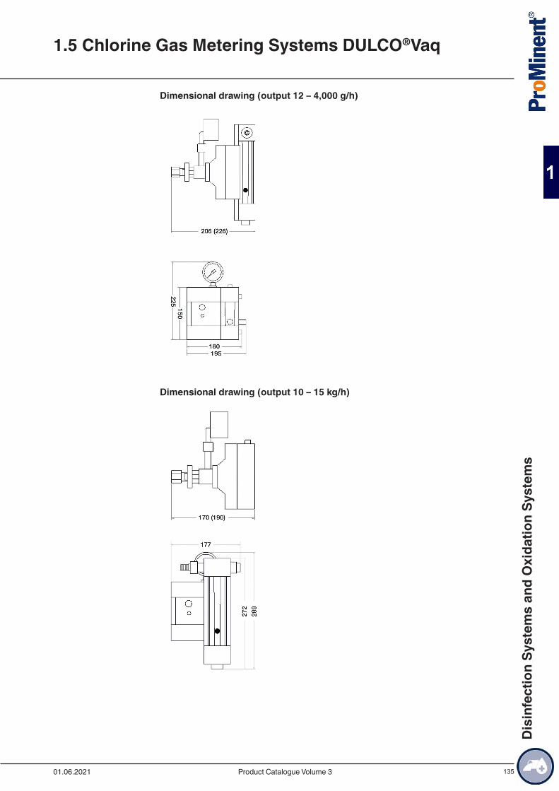
135
Dimensional drawing (output 12 – 4,000 g/h)
Dimensional drawing (output 10 – 15 kg/h)
1.5 Chlorine Gas Metering Systems DULCO®Vaq
01.06.2021 Product Catalogue Volume 3
Dis
infe
ctio
n Sy
stem
s an
d O
xida
tion
Syst
ems
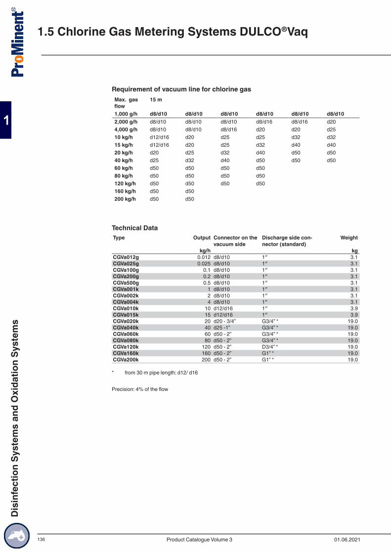
136
Requirement of vacuum line for chlorine gasMax. gas flow
15 m
1,000 g/h d8/d10 d8/d10 d8/d10 d8/d10 d8/d10 d8/d102,000 g/h d8/d10 d8/d10 d8/d10 d8/d16 d8/d16 d204,000 g/h d8/d10 d8/d10 d8/d16 d20 d20 d2510 kg/h d12/d16 d20 d25 d25 d32 d3215 kg/h d12/d16 d20 d25 d32 d40 d4020 kg/h d20 d25 d32 d40 d50 d5040 kg/h d25 d32 d40 d50 d50 d5060 kg/h d50 d50 d50 d50 80 kg/h d50 d50 d50 d50 120 kg/h d50 d50 d50 d50 160 kg/h d50 d50 200 kg/h d50 d50
Technical DataType Output Connector on the
vacuum sideDischarge side con-nector (standard)
Weight
kg/h kgCGVa012g 0.012 d8/d10 1″ 3.1CGVa025g 0.025 d8/d10 1″ 3.1CGVa100g 0.1 d8/d10 1″ 3.1CGVa200g 0.2 d8/d10 1″ 3.1CGVa500g 0.5 d8/d10 1″ 3.1CGVa001k 1 d8/d10 1″ 3.1CGVa002k 2 d8/d10 1″ 3.1CGVa004k 4 d8/d10 1″ 3.1CGVa010k 10 d12/d16 1″ 3.9CGVa015k 15 d12/d16 1″ 3.9CGVa020k 20 d20 - 3/4” G3/4” * 19.0CGVa040k 40 d25 -1” G3/4” * 19.0CGVa060k 60 d50 - 2” G3/4” * 19.0CGVa080k 80 d50 - 2” G3/4” * 19.0CGVa120k 120 d50 - 2” D3/4” * 19.0CGVa160k 160 d50 - 2” G1” * 19.0CGVa200k 200 d50 - 2” G1” * 19.0
* from 30 m pipe length: d12/ d16
Precision: 4% of the flow
1.5 Chlorine Gas Metering Systems DULCO®Vaq
01.06.2021Product Catalogue Volume 3
Dis
infe
ctio
n Sy
stem
s an
d O
xida
tion
Syst
ems
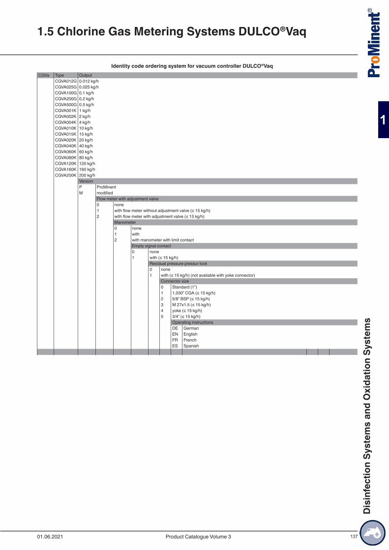
137
Identity code ordering system for vacuum controller DULCO®VaqCGVa Type Output
CGVA012G 0.012 kg/hCGVA025G 0.025 kg/hCGVA100G 0.1 kg/hCGVA200G 0.2 kg/hCGVA500G 0.5 kg/hCGVA001K 1 kg/hCGVA002K 2 kg/hCGVA004K 4 kg/hCGVA010K 10 kg/hCGVA015K 15 kg/hCGVA020K 20 kg/hCGVA040K 40 kg/hCGVA060K 60 kg/hCGVA080K 80 kg/hCGVA120K 120 kg/hCGVA160K 160 kg/hCGVA200K 200 kg/h
VersionP ProMinentM modified
Flow meter with adjustment valve0 none1 with flow meter without adjustment valve (≤ 15 kg/h)2 with flow meter with adjustment valve (≤ 15 kg/h)
Manometer0 none1 with2 with manometer with limit contact
Empty signal contact0 none1 with (≤ 15 kg/h)
Residual pressure pressur lock0 none1 with (≤ 15 kg/h) (not available with yoke connector)
Connector size0 Standard (1”)1 1,030” CGA (≤ 15 kg/h)2 5/8” BSP (≤ 15 kg/h)3 M 27x1.5 (≤ 15 kg/h)4 yoke (≤ 15 kg/h)5 3/4” (≤ 15 kg/h)
Operating instructionsDE GermanEN EnglishFR FrenchES Spanish
1.5 Chlorine Gas Metering Systems DULCO®Vaq
01.06.2021 Product Catalogue Volume 3
Dis
infe
ctio
n Sy
stem
s an
d O
xida
tion
Syst
ems
138
Vacuum controller accessories
Flow limiter 900 g/h
For limiting the throughput of a vacuum controller to 900 g/h for instance with continuously extraction from multiple cylinders. Designed as a PVDF fitting, screwed into the output of the vacuum controller.
Order no.Flow limiter 900 g/h 1082816
1.5 Chlorine Gas Metering Systems DULCO®Vaq
01.06.2021Product Catalogue Volume 3
Dis
infe
ctio
n Sy
stem
s an
d O
xida
tion
Syst
ems
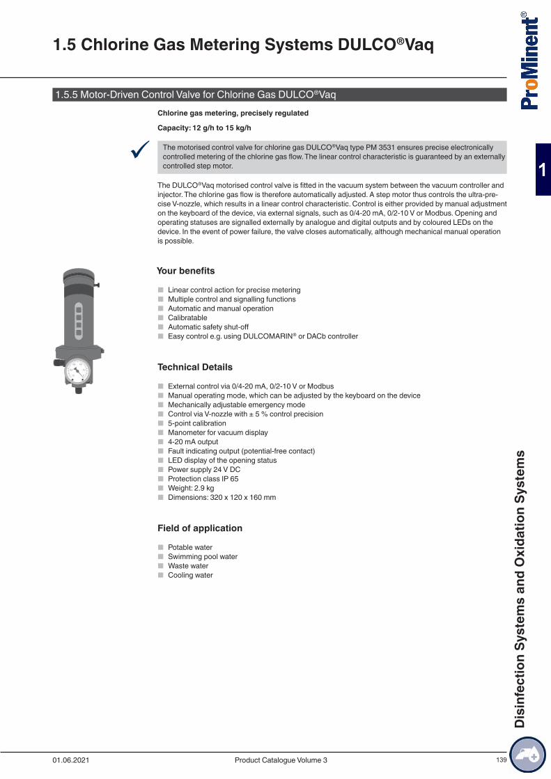
139
1.5.5 Motor-Driven Control Valve for Chlorine Gas DULCO®VaqChlorine gas metering, precisely regulated
Capacity: 12 g/h to 15 kg/h
9 The motorised control valve for chlorine gas DULCO®Vaq type PM 3531 ensures precise electronically controlled metering of the chlorine gas flow. The linear control characteristic is guaranteed by an externally controlled step motor.
The DULCO®Vaq motorised control valve is fitted in the vacuum system between the vacuum controller and injector. The chlorine gas flow is therefore automatically adjusted. A step motor thus controls the ultra-pre-cise V-nozzle, which results in a linear control characteristic. Control is either provided by manual adjustment on the keyboard of the device, via external signals, such as 0/4-20 mA, 0/2-10 V or Modbus. Opening and operating statuses are signalled externally by analogue and digital outputs and by coloured LEDs on the device. In the event of power failure, the valve closes automatically, although mechanical manual operation is possible.
Your benefits
■ Linear control action for precise metering ■ Multiple control and signalling functions ■ Automatic and manual operation ■ Calibratable ■ Automatic safety shut-off ■ Easy control e.g. using DULCOMARIN® or DACb controller
Technical Details
■ External control via 0/4-20 mA, 0/2-10 V or Modbus ■ Manual operating mode, which can be adjusted by the keyboard on the device ■ Mechanically adjustable emergency mode ■ Control via V-nozzle with ± 5 % control precision ■ 5-point calibration ■ Manometer for vacuum display ■ 4-20 mA output ■ Fault indicating output (potential-free contact) ■ LED display of the opening status ■ Power supply 24 V DC ■ Protection class IP 65 ■ Weight: 2.9 kg ■ Dimensions: 320 x 120 x 160 mm
Field of application
■ Potable water ■ Swimming pool water ■ Waste water ■ Cooling water
1.5 Chlorine Gas Metering Systems DULCO®Vaq
01.06.2021 Product Catalogue Volume 3
Dis
infe
ctio
n Sy
stem
s an
d O
xida
tion
Syst
ems

140
Technical Data
with vacuum meterOutput Connection size Order no.kg/h 0.012 d8/d10 10771970.025 d8/d10 10771980.1 d8/d10 10771990.2 d8/d10 10772000.5 d8/d10 10772011 d8/d10 10772022 d8/d10 10772034 d8/d10 107720410 d12/d16 107720515 d12/d16 1077207
without vacuum meterOutput Connection size Order no.kg/h 0.012 d8/d10 10784220.25 d8/d10 10784250.1 d8/d10 10777230.2 d8/d10 10777640.5 d8/d10 10784261 d8/d10 10784272 d8/d10 10784284 d8/d10 107842910 d12/d16 107843015 d12/d16 1078432
! Note: A flow meter needs to be fitted to read off the exact flow and calibrate the motorised control valve. Not included in the scope of delivery.
1.5 Chlorine Gas Metering Systems DULCO®Vaq
01.06.2021Product Catalogue Volume 3
Dis
infe
ctio
n Sy
stem
s an
d O
xida
tion
Syst
ems
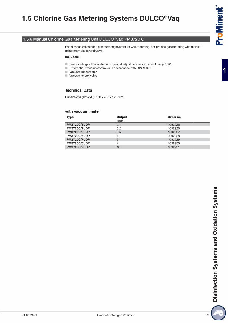
141
1.5.6 Manual Chlorine Gas Metering Unit DULCO®Vaq PM3720 CPanel-mounted chlorine gas metering system for wall mounting. For precise gas metering with manual adjustment via control valve.
Includes:
■ Long-scale gas flow meter with manual adjustment valve; control range 1:20 ■ Differential pressure controller in accordance with DIN 19606 ■ Vacuum manometer ■ Vacuum check valve
Technical DataDimensions (HxWxD): 500 x 400 x 120 mm
with vacuum meterType Output Order no. kg/h PM3720C/3UDP 0.1 1092925PM3720C/4UDP 0.2 1092926PM3720C/5UDP 0.5 1092927PM3720C/6UDP 1 1092928PM3720C/7UDP 2 1092929PM3720C/8UDP 4 1092930PM3720C/9UDP 10 1092931
1.5 Chlorine Gas Metering Systems DULCO®Vaq
01.06.2021 Product Catalogue Volume 3
Dis
infe
ctio
n Sy
stem
s an
d O
xida
tion
Syst
ems

142
1.5.7 Automatic Chlorine Gas Metering System DULCO®VaqMaximum safety and precision in chlorine gas metering.
Capacity: 12 g/h - 15 kg/h
9 The chlorine gas metering system DULCO®Vaq type PM 3610 C for automatically controlled metering of chlorine gas. Its simple operation offers safety and precision in accordance with the current state of tech-nology and in line with DIN standards.
The automatic chlorine gas metering system DULCO®Vaq type PM 3610 C is fitted in the vacuum system between the vacuum controller and injector. The chlorine gas flow is automatically adjusted. A stepper motor controls an ultra-precise V-nozzle, enabling a linear control characteristic over a wide range. Control is by means of external control, such as analogue signals, 0/2 - 10 V, Modbus or by manually setting on the device’s keypad. Opening and operating statuses are signalled externally by analogue and digital outputs and by LEDs on the device. In the event of power failure, the valve closes automatically, although mechani-cal manual operation is possible. The flow of chlorine gas is displayed on a long-scale flow meter and is held constant by the integrated differential pressure regulator even with fluctuating pressure conditions.
Manometers display both the injector vacuum as well as the operating vacuum.
The entire system is ready-wired and mounted on a PVC panel and protected by an appropriate cover.
Your benefits
■ Automatic chlorine gas metering ■ Plug and Play ■ DIN 19606-compliant ■ Panel-mounted system ■ Wide-ranging controllable motorised control valve ■ Functional cover hood
Technical DetailsFull-vacuum chlorine gas metering unit type PM 3610 C including:
■ motorised control valve PM 3531 C, capacity up to 15 kg/h with C-control nozzle with 1:20 controllability, with automatic proportional metering via a 4-20 mA signal.
■ LED indicator for the opening status ■ 5-point calibration ■ Simple, manual or automatic operation ■ Potential-free contact for error signalling ■ Long-scale flow meter (165 mm) with a precision of ± 4 % ■ Differential pressure controller in accordance with DIN 19606 ■ Manometer to display the operating vacuum ■ Manometer to display the injector vacuum ■ Non-return valve on the outlet side ■ Power supply: 230 VAC 50/60 Hz ■ Degree of protection: IP67 ■ Pipework: PVC-U PN16 ■ Vacuum switch (vacuum too high / vacuum too low) (-HL)
Field of application
■ Potable water ■ Swimming pool ■ Waste water ■ Cooling water
1.5 Chlorine Gas Metering Systems DULCO®Vaq
01.06.2021Product Catalogue Volume 3
Dis
infe
ctio
n Sy
stem
s an
d O
xida
tion
Syst
ems
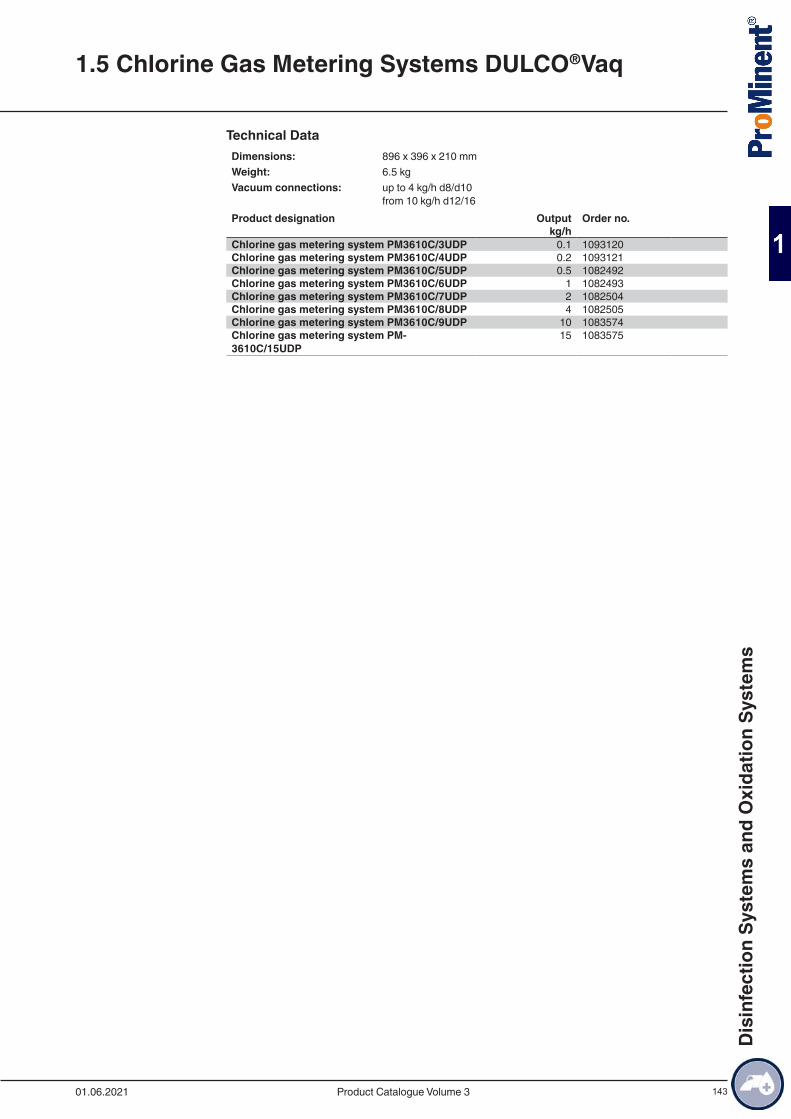
143
Technical DataDimensions: 896 x 396 x 210 mmWeight: 6.5 kgVacuum connections: up to 4 kg/h d8/d10
from 10 kg/h d12/16Product designation Output Order no. kg/h Chlorine gas metering system PM3610C/3UDP 0.1 1093120Chlorine gas metering system PM3610C/4UDP 0.2 1093121Chlorine gas metering system PM3610C/5UDP 0.5 1082492Chlorine gas metering system PM3610C/6UDP 1 1082493Chlorine gas metering system PM3610C/7UDP 2 1082504Chlorine gas metering system PM3610C/8UDP 4 1082505Chlorine gas metering system PM3610C/9UDP 10 1083574Chlorine gas metering system PM-3610C/15UDP
15 1083575
1.5 Chlorine Gas Metering Systems DULCO®Vaq
01.06.2021 Product Catalogue Volume 3
Dis
infe
ctio
n Sy
stem
s an
d O
xida
tion
Syst
ems
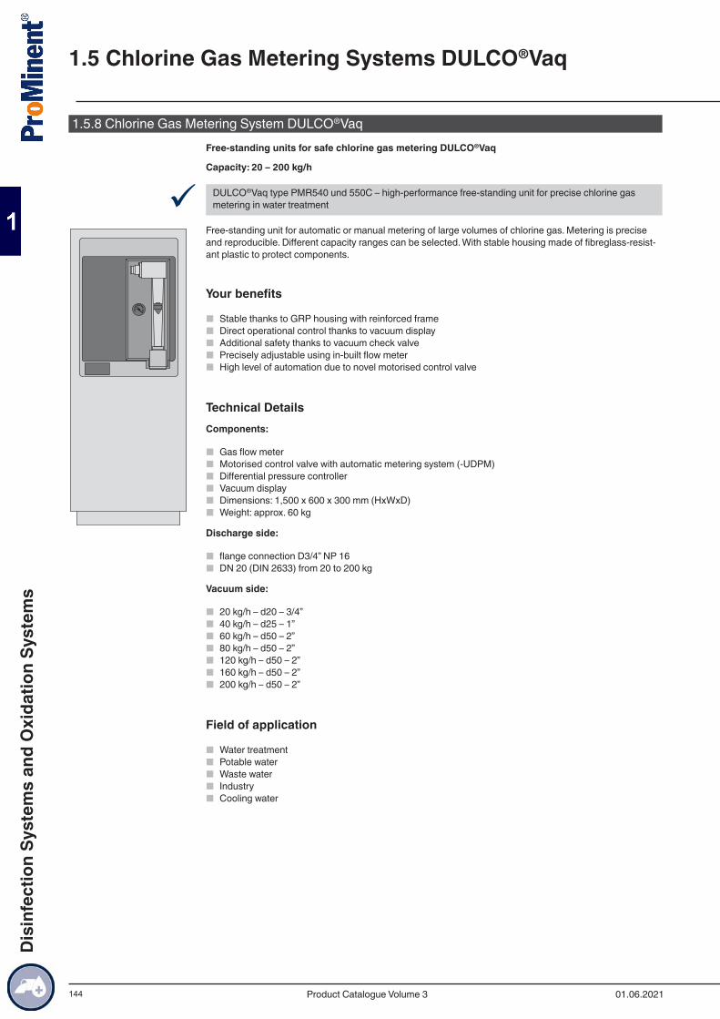
144
1.5.8 Chlorine Gas Metering System DULCO®VaqFree-standing units for safe chlorine gas metering DULCO®Vaq
Capacity: 20 – 200 kg/h
9 DULCO®Vaq type PMR540 und 550C – high-performance free-standing unit for precise chlorine gas metering in water treatment
Free-standing unit for automatic or manual metering of large volumes of chlorine gas. Metering is precise and reproducible. Different capacity ranges can be selected. With stable housing made of fibreglass-resist-ant plastic to protect components.
Your benefits
■ Stable thanks to GRP housing with reinforced frame ■ Direct operational control thanks to vacuum display ■ Additional safety thanks to vacuum check valve ■ Precisely adjustable using in-built flow meter ■ High level of automation due to novel motorised control valve
Technical DetailsComponents:
■ Gas flow meter ■ Motorised control valve with automatic metering system (-UDPM) ■ Differential pressure controller ■ Vacuum display ■ Dimensions: 1,500 x 600 x 300 mm (HxWxD) ■ Weight: approx. 60 kg
Discharge side:
■ flange connection D3/4” NP 16 ■ DN 20 (DIN 2633) from 20 to 200 kg
Vacuum side:
■ 20 kg/h – d20 – 3/4” ■ 40 kg/h – d25 – 1” ■ 60 kg/h – d50 – 2” ■ 80 kg/h – d50 – 2” ■ 120 kg/h – d50 – 2” ■ 160 kg/h – d50 – 2” ■ 200 kg/h – d50 – 2”
Field of application
■ Water treatment ■ Potable water ■ Waste water ■ Industry ■ Cooling water
1.5 Chlorine Gas Metering Systems DULCO®Vaq
01.06.2021Product Catalogue Volume 3
Dis
infe
ctio
n Sy
stem
s an
d O
xida
tion
Syst
ems
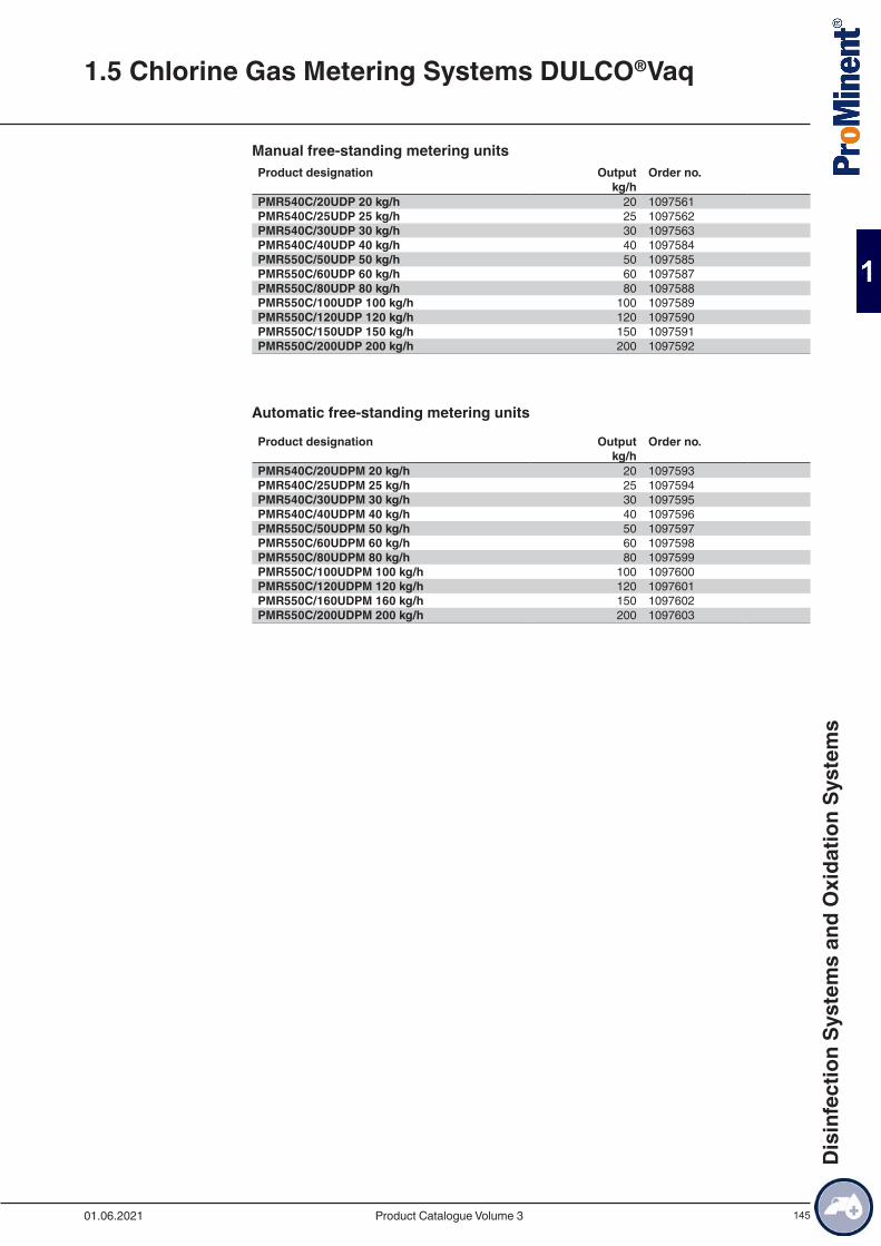
145
Manual free-standing metering unitsProduct designation Output Order no. kg/h PMR540C/20UDP 20 kg/h 20 1097561PMR540C/25UDP 25 kg/h 25 1097562PMR540C/30UDP 30 kg/h 30 1097563PMR540C/40UDP 40 kg/h 40 1097584PMR550C/50UDP 50 kg/h 50 1097585PMR550C/60UDP 60 kg/h 60 1097587PMR550C/80UDP 80 kg/h 80 1097588PMR550C/100UDP 100 kg/h 100 1097589PMR550C/120UDP 120 kg/h 120 1097590PMR550C/150UDP 150 kg/h 150 1097591PMR550C/200UDP 200 kg/h 200 1097592
Automatic free-standing metering units
Product designation Output Order no. kg/h PMR540C/20UDPM 20 kg/h 20 1097593PMR540C/25UDPM 25 kg/h 25 1097594PMR540C/30UDPM 30 kg/h 30 1097595PMR540C/40UDPM 40 kg/h 40 1097596PMR550C/50UDPM 50 kg/h 50 1097597PMR550C/60UDPM 60 kg/h 60 1097598PMR550C/80UDPM 80 kg/h 80 1097599PMR550C/100UDPM 100 kg/h 100 1097600PMR550C/120UDPM 120 kg/h 120 1097601PMR550C/160UDPM 160 kg/h 150 1097602PMR550C/200UDPM 200 kg/h 200 1097603
1.5 Chlorine Gas Metering Systems DULCO®Vaq
01.06.2021 Product Catalogue Volume 3
Dis
infe
ctio
n Sy
stem
s an
d O
xida
tion
Syst
ems
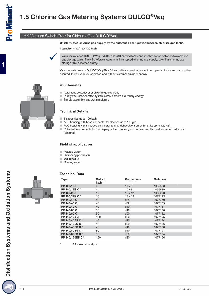
146
1.5.9 Vacuum Switch-Over for Chlorine Gas DULCO®VaqUninterrupted chlorine gas supply by the automatic changeover between chlorine gas tanks.
Capacity: 4 kg/h to 120 kg/h
9 Vacuum switches DULCO®Vaq PM 400 and 440 automatically and reliably switch between two chlorine gas storage tanks. They therefore ensure an uninterrupted chlorine gas supply, even if a chlorine gas storage tank becomes empty.
Vacuum switch-overs DULCO®Vaq PM 400 and 440 are used where uninterrupted chlorine supply must be ensured. Purely vacuum-operated and without external auxiliary energy.
Your benefits
■ Automatic switchover of chlorine gas sources ■ Purely vacuum-operated system without external auxiliary energy ■ Simple assembly and commissioning
Technical Details
■ 5 capacities up to 120 kg/h ■ ABS housing with hose connector for devices up to 10 kg/h ■ PVC housing with threaded connector and straight solvent union for units up to 120 kg/h ■ Potential-free contacts for the display of the chlorine gas source currently used via an indicator box
(optional)
Field of application
■ Potable water ■ Swimming pool water ■ Waste water ■ Cooling water
Technical DataType Output Connectors Order no. kg/h PM400/1 C 4 10 x 8 1055838PM400/1ES C * 4 10 x 8 1055839PM400/2 C 10 16 x 12 1060293PM400/2ES C * 10 16 x 12 1077183PM440/40 C 40 d25 1075780PM440/40 C 40 d32 1077185PM440/40 C 40 d40 1077187PM440/80 C 80 d40 1077190PM440/80 C 80 d50 1077192PM440/120 C 120 d50 1077195PM440/40ES C * 40 d25 1077184PM440/40ES C * 40 d32 1077186PM440/40ES C * 40 d40 1077188PM440/80ES C * 80 d40 1077191PM440/80ES C * 80 d50 1077194PM440/120ES C * 120 d50 1077196
* ES = electrical signal
1.5 Chlorine Gas Metering Systems DULCO®Vaq
01.06.2021Product Catalogue Volume 3
Dis
infe
ctio
n Sy
stem
s an
d O
xida
tion
Syst
ems
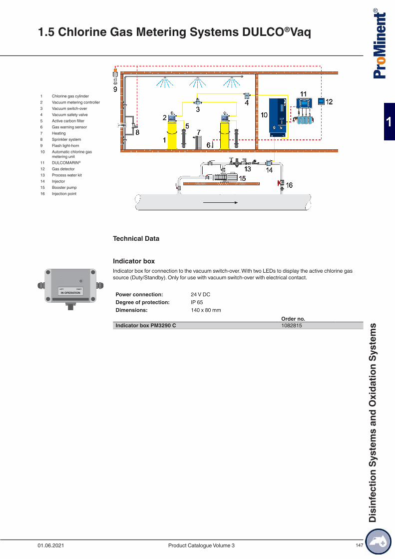
147
1 Chlorine gas cylinder2 Vacuum metering controller3 Vacuum switch-over4 Vacuum safety valve5 Active carbon filter6 Gas warning sensor7 Heating8 Sprinkler system9 Flash light-horn10 Automatic chlorine gas
metering unit11 DULCOMARIN®
12 Gas detector13 Process water kit14 Injector15 Booster pump16 Injection point
Technical Data
Indicator boxIndicator box for connection to the vacuum switch-over. With two LEDs to display the active chlorine gas source (Duty/Standby). Only for use with vacuum switch-over with electrical contact.
Power connection: 24 V DCDegree of protection: IP 65Dimensions: 140 x 80 mm
Order no.Indicator box PM3290 C 1082815
1.5 Chlorine Gas Metering Systems DULCO®Vaq
01.06.2021 Product Catalogue Volume 3
Dis
infe
ctio
n Sy
stem
s an
d O
xida
tion
Syst
ems
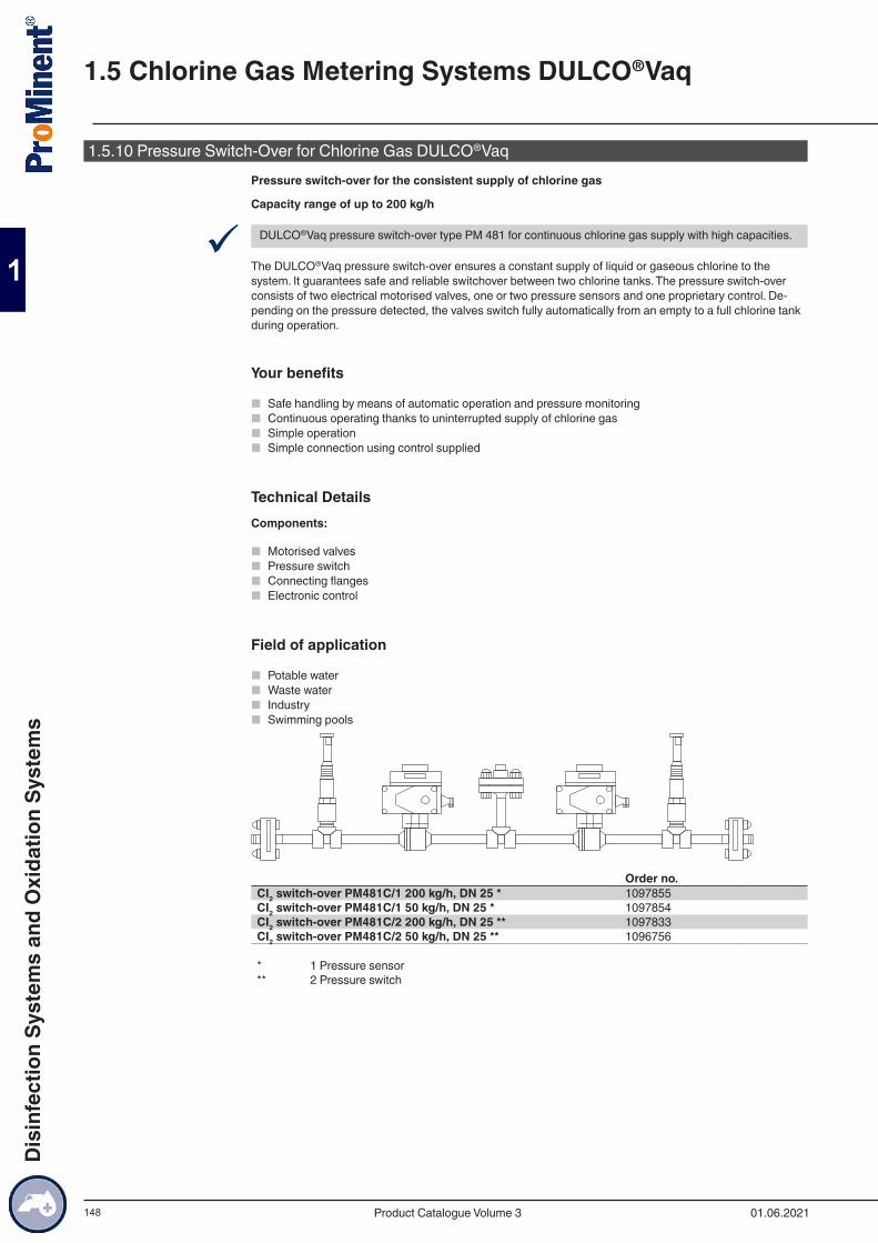
148
1.5.10 Pressure Switch-Over for Chlorine Gas DULCO®VaqPressure switch-over for the consistent supply of chlorine gas
Capacity range of up to 200 kg/h
9 DULCO®Vaq pressure switch-over type PM 481 for continuous chlorine gas supply with high capacities.
The DULCO®Vaq pressure switch-over ensures a constant supply of liquid or gaseous chlorine to the system. It guarantees safe and reliable switchover between two chlorine tanks. The pressure switch-over consists of two electrical motorised valves, one or two pressure sensors and one proprietary control. De-pending on the pressure detected, the valves switch fully automatically from an empty to a full chlorine tank during operation.
Your benefits
■ Safe handling by means of automatic operation and pressure monitoring ■ Continuous operating thanks to uninterrupted supply of chlorine gas ■ Simple operation ■ Simple connection using control supplied
Technical DetailsComponents:
■ Motorised valves ■ Pressure switch ■ Connecting flanges ■ Electronic control
Field of application
■ Potable water ■ Waste water ■ Industry ■ Swimming pools
Order no.CI2 switch-over PM481C/1 200 kg/h, DN 25 * 1097855CI2 switch-over PM481C/1 50 kg/h, DN 25 * 1097854CI2 switch-over PM481C/2 200 kg/h, DN 25 ** 1097833CI2 switch-over PM481C/2 50 kg/h, DN 25 ** 1096756
* 1 Pressure sensor** 2 Pressure switch
1.5 Chlorine Gas Metering Systems DULCO®Vaq
01.06.2021Product Catalogue Volume 3
Dis
infe
ctio
n Sy
stem
s an
d O
xida
tion
Syst
ems
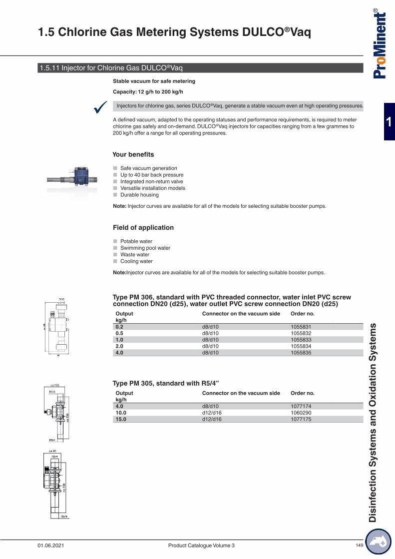
149
1.5.11 Injector for Chlorine Gas DULCO®VaqStable vacuum for safe metering
Capacity: 12 g/h to 200 kg/h
9 Injectors for chlorine gas, series DULCO®Vaq, generate a stable vacuum even at high operating pressures.
A defined vacuum, adapted to the operating statuses and performance requirements, is required to meter chlorine gas safely and on-demand. DULCO®Vaq injectors for capacities ranging from a few grammes to 200 kg/h offer a range for all operating pressures.
Your benefits
■ Safe vacuum generation ■ Up to 40 bar back pressure ■ Integrated non-return valve ■ Versatile installation models ■ Durable housing
Note: Injector curves are available for all of the models for selecting suitable booster pumps.
Field of application
■ Potable water ■ Swimming pool water ■ Waste water ■ Cooling water
Note:Injector curves are available for all of the models for selecting suitable booster pumps.
Type PM 306, standard with PVC threaded connector, water inlet PVC screw connection DN20 (d25), water outlet PVC screw connection DN20 (d25)Output Connector on the vacuum side Order no.kg/h 0.2 d8/d10 10558310.5 d8/d10 10558321.0 d8/d10 10558332.0 d8/d10 10558344.0 d8/d10 1055835
Type PM 305, standard with R5/4”Output Connector on the vacuum side Order no.kg/h 4.0 d8/d10 107717410.0 d12/d16 106029015.0 d12/d16 1077175
1.5 Chlorine Gas Metering Systems DULCO®Vaq
01.06.2021 Product Catalogue Volume 3
Dis
infe
ctio
n Sy
stem
s an
d O
xida
tion
Syst
ems

150
Type PM 300, with immersion pipe R3/4”, pressure < 6 bar, water inlet R3/4”, water outlet R3/4”
Output Connector on the vacuum side Order no.kg/h 0.2 d8/d10 10558220.5 d8/d10 10558231.0 d8/d10 10558242.0 d8/d10 10558254.0 d8/d10 1055826
Type PM 301, reinforced for pressure up to 20 bar, water inlet DN 32 (1 1/4”), water outlet DN 32 (1 1/4”)Output Connector on the vacuum side Order no.kg/h 0.2 d8/d10 10558270.5 d8/d10 10558281.0 d8/d10 10558292.0 d8/d10 1055830
Type PM 340, flange DN 50, water inlet DN 50 (2”), water outlet DN 50 (2”)Output Connector on the vacuum side Order no.kg/h 20.0 d20/d25/d32/d40 107717640.0 d20/d25/d32/d40 1077177
Type PM 350, flange DN 80, for pressure < 6 barOutput Water
inletWater outlet Connector on the
vacuum sideOrder no.
kg/h 60 DN 80 (3”) DN 80 (3”) d32/d40/d50 107717880 DN 80 (3”) DN 80 (3”) d32/d40/d50 1077179120 DN 80 (3”) DN 80 (3”) d32/d40/d50 1077180160 pro-
ject-spe-cific
project-spe-cific
- 1077181
200 pro-ject-spe-cific
project-spe-cific
- 1077182
1.5 Chlorine Gas Metering Systems DULCO®Vaq
01.06.2021Product Catalogue Volume 3
Dis
infe
ctio
n Sy
stem
s an
d O
xida
tion
Syst
ems
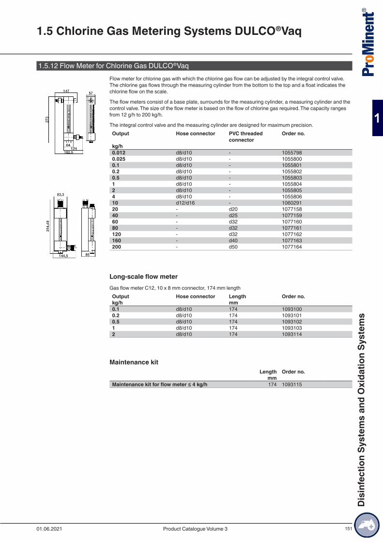
151
1.5.12 Flow Meter for Chlorine Gas DULCO®VaqFlow meter for chlorine gas with which the chlorine gas flow can be adjusted by the integral control valve. The chlorine gas flows through the measuring cylinder from the bottom to the top and a float indicates the chlorine flow on the scale.
The flow meters consist of a base plate, surrounds for the measuring cylinder, a measuring cylinder and the control valve. The size of the flow meter is based on the flow of chlorine gas required. The capacity ranges from 12 g/h to 200 kg/h.
The integral control valve and the measuring cylinder are designed for maximum precision.Output Hose connector PVC threaded
connectorOrder no.
kg/h 0.012 d8/d10 - 10557980.025 d8/d10 - 10558000.1 d8/d10 - 10558010.2 d8/d10 - 10558020.5 d8/d10 - 10558031 d8/d10 - 10558042 d8/d10 - 10558054 d8/d10 - 105580610 d12/d16 - 106029120 - d20 107715840 - d25 107715960 - d32 107716080 - d32 1077161120 - d32 1077162160 - d40 1077163200 - d50 1077164
Long-scale flow meterGas flow meter C12, 10 x 8 mm connector, 174 mm lengthOutput Hose connector Length Order no.kg/h mm 0.1 d8/d10 174 10931000.2 d8/d10 174 10931010.5 d8/d10 174 10931021 d8/d10 174 10931032 d8/d10 174 1093114
Maintenance kitLength Order no.
mmMaintenance kit for flow meter ≤ 4 kg/h 174 1093115
1.5 Chlorine Gas Metering Systems DULCO®Vaq
01.06.2021 Product Catalogue Volume 3
Dis
infe
ctio
n Sy
stem
s an
d O
xida
tion
Syst
ems
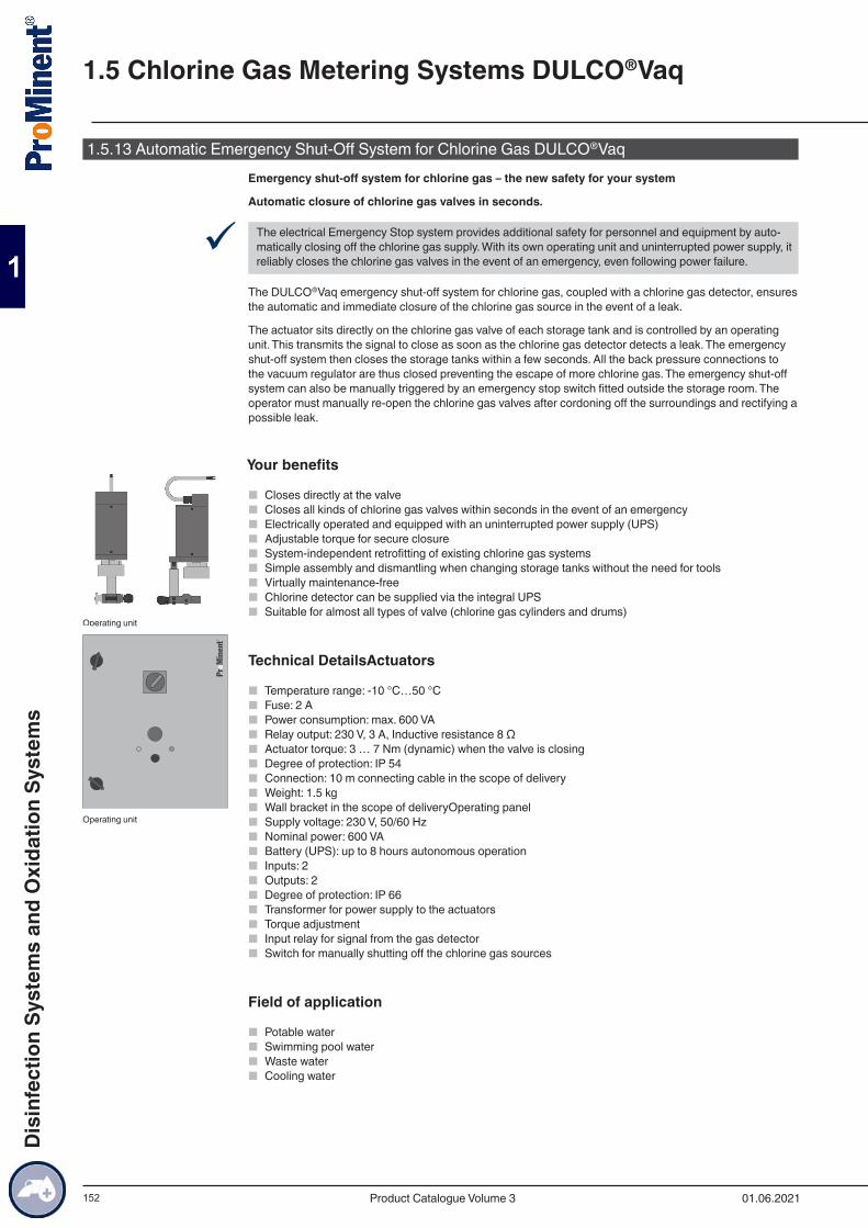
152
1.5.13 Automatic Emergency Shut-Off System for Chlorine Gas DULCO®VaqEmergency shut-off system for chlorine gas – the new safety for your system
Automatic closure of chlorine gas valves in seconds.
9 The electrical Emergency Stop system provides additional safety for personnel and equipment by auto-matically closing off the chlorine gas supply. With its own operating unit and uninterrupted power supply, it reliably closes the chlorine gas valves in the event of an emergency, even following power failure.
The DULCO®Vaq emergency shut-off system for chlorine gas, coupled with a chlorine gas detector, ensures the automatic and immediate closure of the chlorine gas source in the event of a leak.
The actuator sits directly on the chlorine gas valve of each storage tank and is controlled by an operating unit. This transmits the signal to close as soon as the chlorine gas detector detects a leak. The emergency shut-off system then closes the storage tanks within a few seconds. All the back pressure connections to the vacuum regulator are thus closed preventing the escape of more chlorine gas. The emergency shut-off system can also be manually triggered by an emergency stop switch fitted outside the storage room. The operator must manually re-open the chlorine gas valves after cordoning off the surroundings and rectifying a possible leak.
Your benefits
■ Closes directly at the valve ■ Closes all kinds of chlorine gas valves within seconds in the event of an emergency ■ Electrically operated and equipped with an uninterrupted power supply (UPS) ■ Adjustable torque for secure closure ■ System-independent retrofitting of existing chlorine gas systems ■ Simple assembly and dismantling when changing storage tanks without the need for tools ■ Virtually maintenance-free ■ Chlorine detector can be supplied via the integral UPS ■ Suitable for almost all types of valve (chlorine gas cylinders and drums)
Technical DetailsActuators
■ Temperature range: -10 °C…50 °C ■ Fuse: 2 A ■ Power consumption: max. 600 VA ■ Relay output: 230 V, 3 A, Inductive resistance 8 Ω ■ Actuator torque: 3 … 7 Nm (dynamic) when the valve is closing ■ Degree of protection: IP 54 ■ Connection: 10 m connecting cable in the scope of delivery ■ Weight: 1.5 kg ■ Wall bracket in the scope of deliveryOperating panel ■ Supply voltage: 230 V, 50/60 Hz ■ Nominal power: 600 VA ■ Battery (UPS): up to 8 hours autonomous operation ■ Inputs: 2 ■ Outputs: 2 ■ Degree of protection: IP 66 ■ Transformer for power supply to the actuators ■ Torque adjustment ■ Input relay for signal from the gas detector ■ Switch for manually shutting off the chlorine gas sources
Field of application
■ Potable water ■ Swimming pool water ■ Waste water ■ Cooling water
Operating unit
Operating unit
1.5 Chlorine Gas Metering Systems DULCO®Vaq
01.06.2021Product Catalogue Volume 3
Dis
infe
ctio
n Sy
stem
s an
d O
xida
tion
Syst
ems
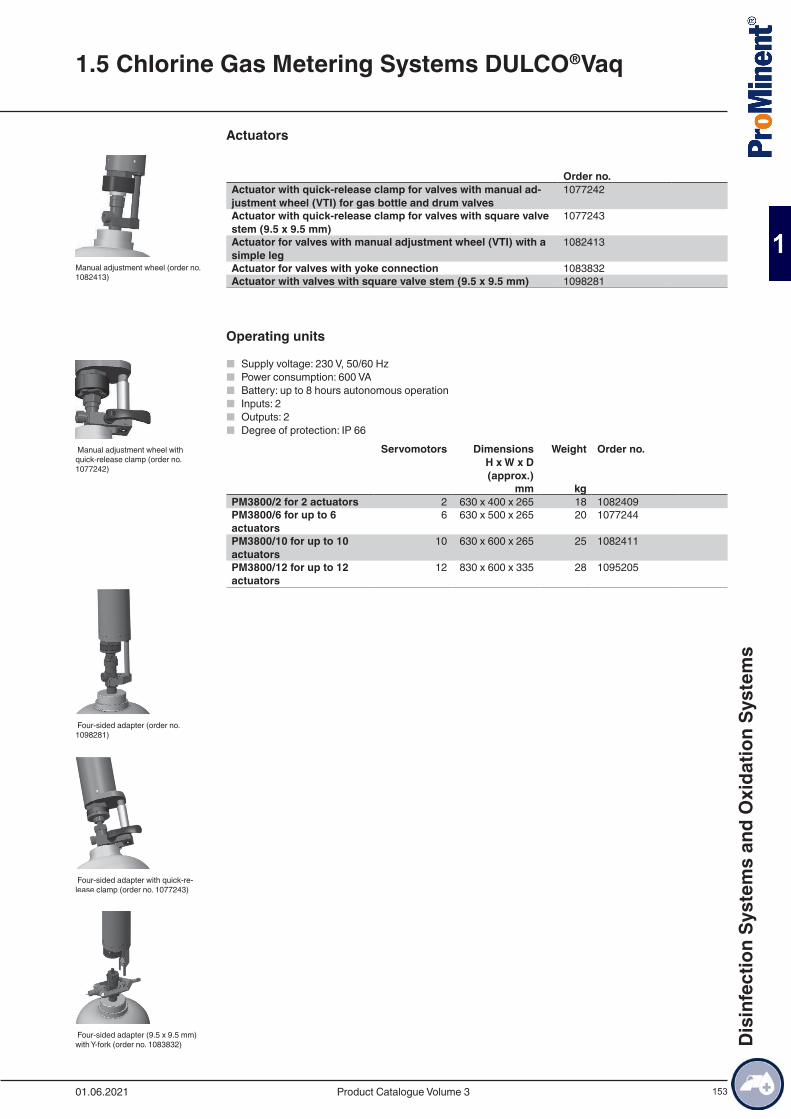
153
Actuators
Order no.Actuator with quick-release clamp for valves with manual ad-justment wheel (VTI) for gas bottle and drum valves
1077242
Actuator with quick-release clamp for valves with square valve stem (9.5 x 9.5 mm)
1077243
Actuator for valves with manual adjustment wheel (VTI) with a simple leg
1082413
Actuator for valves with yoke connection 1083832Actuator with valves with square valve stem (9.5 x 9.5 mm) 1098281
Operating units
■ Supply voltage: 230 V, 50/60 Hz ■ Power consumption: 600 VA ■ Battery: up to 8 hours autonomous operation ■ Inputs: 2 ■ Outputs: 2 ■ Degree of protection: IP 66
Servomotors Dimensions H x W x D (approx.)
Weight Order no.
mm kg PM3800/2 for 2 actuators 2 630 x 400 x 265 18 1082409PM3800/6 for up to 6 actuators
6 630 x 500 x 265 20 1077244
PM3800/10 for up to 10 actuators
10 630 x 600 x 265 25 1082411
PM3800/12 for up to 12 actuators
12 830 x 600 x 335 28 1095205
Manual adjustment wheel (order no. 1082413)
Manual adjustment wheel with quick-release clamp (order no. 1077242)
Four-sided adapter (order no. 1098281)
Four-sided adapter with quick-re-lease clamp (order no. 1077243)
Four-sided adapter (9.5 x 9.5 mm) with Y-fork (order no. 1083832)
1.5 Chlorine Gas Metering Systems DULCO®Vaq
01.06.2021 Product Catalogue Volume 3
Dis
infe
ctio
n Sy
stem
s an
d O
xida
tion
Syst
ems
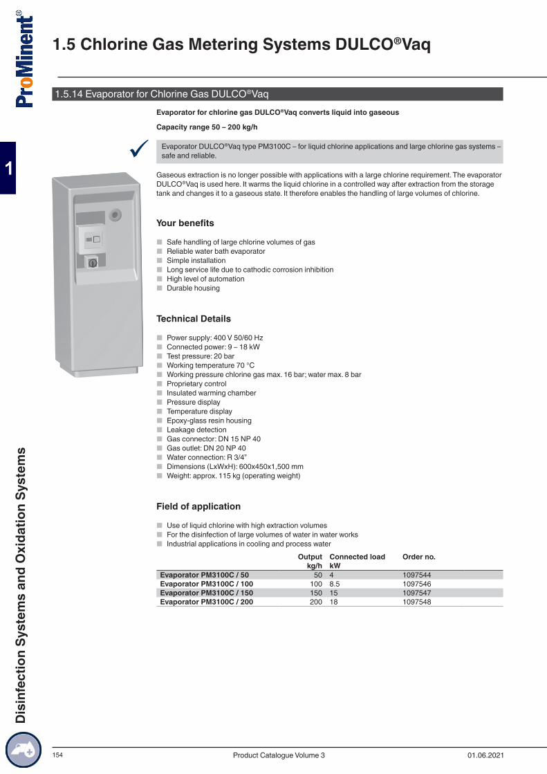
154
1.5.14 Evaporator for Chlorine Gas DULCO®VaqEvaporator for chlorine gas DULCO®Vaq converts liquid into gaseous
Capacity range 50 – 200 kg/h
9 Evaporator DULCO®Vaq type PM3100C – for liquid chlorine applications and large chlorine gas systems – safe and reliable.
Gaseous extraction is no longer possible with applications with a large chlorine requirement. The evaporator DULCO®Vaq is used here. It warms the liquid chlorine in a controlled way after extraction from the storage tank and changes it to a gaseous state. It therefore enables the handling of large volumes of chlorine.
Your benefits
■ Safe handling of large chlorine volumes of gas ■ Reliable water bath evaporator ■ Simple installation ■ Long service life due to cathodic corrosion inhibition ■ High level of automation ■ Durable housing
Technical Details
■ Power supply: 400 V 50/60 Hz ■ Connected power: 9 – 18 kW ■ Test pressure: 20 bar ■ Working temperature 70 °C ■ Working pressure chlorine gas max. 16 bar; water max. 8 bar ■ Proprietary control ■ Insulated warming chamber ■ Pressure display ■ Temperature display ■ Epoxy-glass resin housing ■ Leakage detection ■ Gas connector: DN 15 NP 40 ■ Gas outlet: DN 20 NP 40 ■ Water connection: R 3/4” ■ Dimensions (LxWxH): 600x450x1,500 mm ■ Weight: approx. 115 kg (operating weight)
Field of application
■ Use of liquid chlorine with high extraction volumes ■ For the disinfection of large volumes of water in water works ■ Industrial applications in cooling and process water
Output Connected load Order no.kg/h kW
Evaporator PM3100C / 50 50 4 1097544Evaporator PM3100C / 100 100 8.5 1097546Evaporator PM3100C / 150 150 15 1097547Evaporator PM3100C / 200 200 18 1097548
1.5 Chlorine Gas Metering Systems DULCO®Vaq
01.06.2021Product Catalogue Volume 3
Dis
infe
ctio
n Sy
stem
s an
d O
xida
tion
Syst
ems
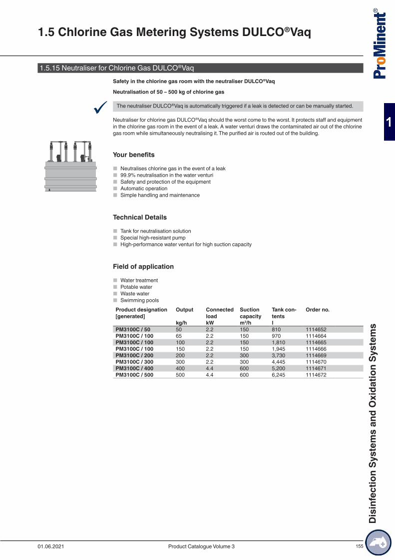
155
1.5.15 Neutraliser for Chlorine Gas DULCO®VaqSafety in the chlorine gas room with the neutraliser DULCO®Vaq
Neutralisation of 50 – 500 kg of chlorine gas
9 The neutraliser DULCO®Vaq is automatically triggered if a leak is detected or can be manually started.
Neutraliser for chlorine gas DULCO®Vaq should the worst come to the worst. It protects staff and equipment in the chlorine gas room in the event of a leak. A water venturi draws the contaminated air out of the chlorine gas room while simultaneously neutralising it. The purified air is routed out of the building.
Your benefits
■ Neutralises chlorine gas in the event of a leak ■ 99.9% neutralisation in the water venturi ■ Safety and protection of the equipment ■ Automatic operation ■ Simple handling and maintenance
Technical Details
■ Tank for neutralisation solution ■ Special high-resistant pump ■ High-performance water venturi for high suction capacity
Field of application
■ Water treatment ■ Potable water ■ Waste water ■ Swimming pools
Product designation [generated]
Output Connected load
Suction capacity
Tank con-tents
Order no.
kg/h kW m3/h l PM3100C / 50 50 2.2 150 810 1114652PM3100C / 100 65 2.2 150 970 1114664PM3100C / 100 100 2.2 150 1,810 1114665PM3100C / 100 150 2.2 150 1,945 1114666PM3100C / 200 200 2.2 300 3,730 1114669PM3100C / 300 300 2.2 300 4,445 1114670PM3100C / 400 400 4.4 600 5,200 1114671PM3100C / 500 500 4.4 600 6,245 1114672
1.5 Chlorine Gas Metering Systems DULCO®Vaq
01.06.2021 Product Catalogue Volume 3
Dis
infe
ctio
n Sy
stem
s an
d O
xida
tion
Syst
ems
156
1.5.16 Accessories for Chlorine Gas Metering
Active carbon absorption tankAbsorption storage tank for chlorine gas with active carbon filling.
For the connection to the safety vent of the vacuum regulator.Order no.
Active carbon filter 1055840Replacement filling (3 kg) 1075273
Vacuum safety valveThe vacuum safety valve PM 3903 according to DIN 19606 is used to protect the installation from the possi-ble build-up of pressure in the vacuum line.
Order no.Vacuum safety valve, 15 kg/h, d20 threaded connector 1103039Vacuum safety valve, 4 kg/h, 10 x 8 mm connector 1082416Vacuum safety valve, 15 kg/h, 16 x 12 mm connector 1082417Maintenance kit for vacuum safety valve PM3903 4 kg/h 1096390Maintenance kit for vacuum safety valve PM3903 15 kg/h 1096391
Vacuum lineVacuum-resistant PE hose material to connect up the components in the chlorine gas metering system.
Order no.Hose PE-LD d8/d10 1055837Hose PE-LD d12/d16 1077236T-hose connector d12/d16 to d8/d10 1095446L-hose connector d12/d16 to d8/d10 1095447
Vacuum shut-off valveManual shut-off valve PVC-U for installation in the vacuum line.
Order no.Cl2 vacuum shut-off valve d10x8 1056321Cl2 vacuum shut-off valve d16x12 1056322
Chlorine gas non-return valve PM3901Mechanical non-return valve for the vacuum line. As additional backup against the ingress of water from the injector into the chlorine gas metering system.
Order no.Non-return valve 10x8 PVC-U 1055836Non-return valve 15 kg/h 16x12 PVC-U 1075781Non-return valve 40 kg/h DN 25 PVC-U 1077240Non-return valve 120 kg/h DN 50 PVC-U 1077241
Differential pressure regulatorThe differential pressure regulator adjusts any fluctuations within the vacuum before and after the rate valve and ensures constant metering. Complies with DIN 19606.
1.5 Chlorine Gas Metering Systems DULCO®Vaq
01.06.2021Product Catalogue Volume 3
Dis
infe
ctio
n Sy
stem
s an
d O
xida
tion
Syst
ems
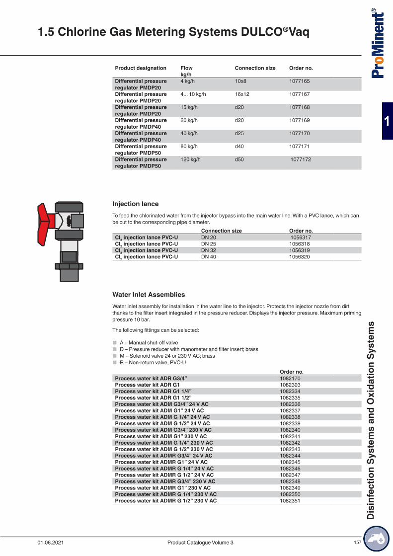
157
Product designation Flow Connection size Order no. kg/h Differential pressure regulator PMDP20
4 kg/h 10x8 1077165
Differential pressure regulator PMDP20
4... 10 kg/h 16x12 1077167
Differential pressure regulator PMDP20
15 kg/h d20 1077168
Differential pressure regulator PMDP40
20 kg/h d20 1077169
Differential pressure regulator PMDP40
40 kg/h d25 1077170
Differential pressure regulator PMDP50
80 kg/h d40 1077171
Differential pressure regulator PMDP50
120 kg/h d50 1077172
Injection lanceTo feed the chlorinated water from the injector bypass into the main water line. With a PVC lance, which can be cut to the corresponding pipe diameter.
Connection size Order no.Cl2 injection lance PVC-U DN 20 1056317Cl2 injection lance PVC-U DN 25 1056318Cl2 injection lance PVC-U DN 32 1056319Cl2 injection lance PVC-U DN 40 1056320
Water Inlet AssembliesWater inlet assembly for installation in the water line to the injector. Protects the injector nozzle from dirt thanks to the filter insert integrated in the pressure reducer. Displays the injector pressure. Maximum priming pressure 10 bar.
The following fittings can be selected:
■ A – Manual shut-off valve ■ D – Pressure reducer with manometer and filter insert; brass ■ M – Solenoid valve 24 or 230 V AC; brass ■ R – Non-return valve, PVC-U
Order no.Process water kit ADR G3/4” 1082170Process water kit ADR G1 1082303Process water kit ADR G1 1/4” 1082334Process water kit ADR G1 1/2” 1082335Process water kit ADM G3/4” 24 V AC 1082336Process water kit ADM G1” 24 V AC 1082337Process water kit ADM G 1/4” 24 V AC 1082338Process water kit ADM G 1/2” 24 V AC 1082339Process water kit ADM G3/4” 230 V AC 1082340Process water kit ADM G1” 230 V AC 1082341Process water kit ADM G 1/4” 230 V AC 1082342Process water kit ADM G 1/2” 230 V AC 1082343Process water kit ADMR G3/4” 24 V AC 1082344Process water kit ADMR G1” 24 V AC 1082345Process water kit ADMR G 1/4” 24 V AC 1082346Process water kit ADMR G 1/2” 24 V AC 1082347Process water kit ADMR G3/4” 230 V AC 1082348Process water kit ADMR G1” 230 V AC 1082349Process water kit ADMR G 1/4” 230 V AC 1082350Process water kit ADMR G 1/2” 230 V AC 1082351
1.5 Chlorine Gas Metering Systems DULCO®Vaq
01.06.2021 Product Catalogue Volume 3
Dis
infe
ctio
n Sy
stem
s an
d O
xida
tion
Syst
ems
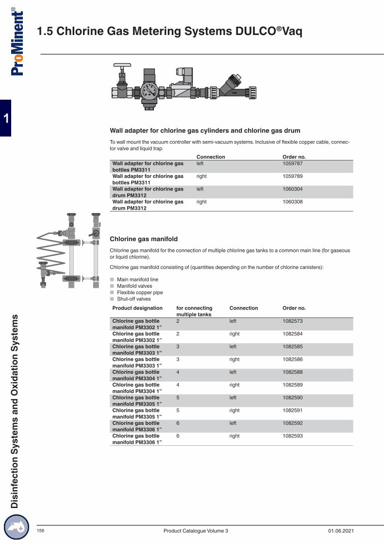
158
Wall adapter for chlorine gas cylinders and chlorine gas drumTo wall mount the vacuum controller with semi-vacuum systems. Inclusive of flexible copper cable, connec-tor valve and liquid trap.
Connection Order no.Wall adapter for chlorine gas bottles PM3311
left 1059787
Wall adapter for chlorine gas bottles PM3311
right 1059789
Wall adapter for chlorine gas drum PM3312
left 1060304
Wall adapter for chlorine gas drum PM3312
right 1060308
Chlorine gas manifoldChlorine gas manifold for the connection of multiple chlorine gas tanks to a common main line (for gaseous or liquid chlorine).
Chlorine gas manifold consisting of (quantities depending on the number of chlorine canisters):
■ Main manifold line ■ Manifold valves ■ Flexible copper pipe ■ Shut-off valves
Product designation for connecting multiple tanks
Connection Order no.
Chlorine gas bottle manifold PM3302 1”
2 left 1082573
Chlorine gas bottle manifold PM3302 1”
2 right 1082584
Chlorine gas bottle manifold PM3303 1”
3 left 1082585
Chlorine gas bottle manifold PM3303 1”
3 right 1082586
Chlorine gas bottle manifold PM3304 1”
4 left 1082588
Chlorine gas bottle manifold PM3304 1”
4 right 1082589
Chlorine gas bottle manifold PM3305 1”
5 left 1082590
Chlorine gas bottle manifold PM3305 1”
5 right 1082591
Chlorine gas bottle manifold PM3306 1”
6 left 1082592
Chlorine gas bottle manifold PM3306 1”
6 right 1082593
1.5 Chlorine Gas Metering Systems DULCO®Vaq
01.06.2021Product Catalogue Volume 3
Dis
infe
ctio
n Sy
stem
s an
d O
xida
tion
Syst
ems
159
Product designation for connecting multiple tanks
Connection Order no.
Manifold for chlorine gas vessel PM3322 1”
2 left 1075771
Manifold for chlorine gas vessel PM3322 1”
2 right 1075772
Manifold for chlorine gas vessel PM3323 1”
3 left 1082596
Manifold for chlorine gas vessel PM3323 1”
3 right 1082597
Manifold for chlorine gas vessel PM3324 1”
4 left 1082598
Manifold for chlorine gas vessel PM3324 1”
4 right 1082599
Manifold for chlorine gas vessel PM3325 1”
5 left 1082600
Manifold for chlorine gas vessel PM3325 1”
5 right 1082601
Manifold for chlorine gas vessel PM3326 1”
6 left 1082602
Manifold for chlorine gas vessel PM3326 1”
6 right 1082603
! Note: The right and left side of the manifold must be ordered if a switch-over is used.
Heating kitSelf-limiting heating band whose heat output decreases as the temperature rises. Output 15 W/m. incl. terminal kit and temperature sensor Pt100, length 10 m.
Order no.Complete heating set for chlorine gas manifold, 230 V 1082707
1.5 Chlorine Gas Metering Systems DULCO®Vaq
01.06.2021 Product Catalogue Volume 3
Dis
infe
ctio
n Sy
stem
s an
d O
xida
tion
Syst
ems
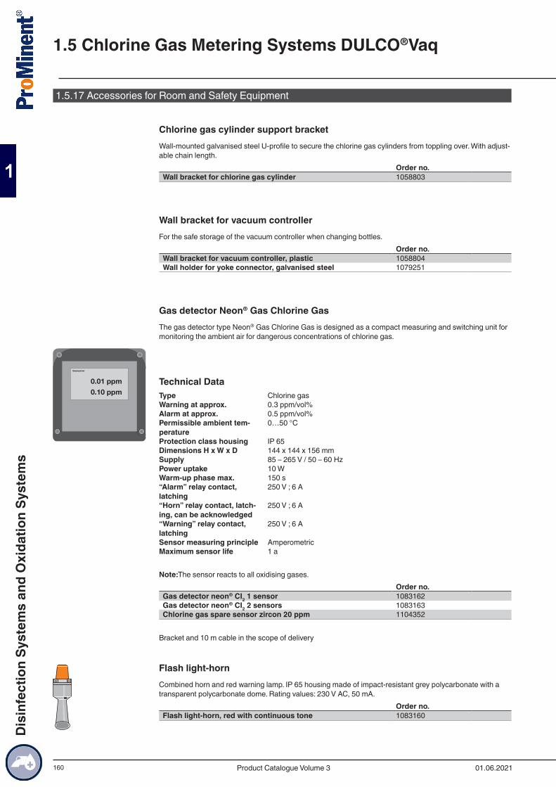
160
1.5.17 Accessories for Room and Safety Equipment
Chlorine gas cylinder support bracketWall-mounted galvanised steel U-profile to secure the chlorine gas cylinders from toppling over. With adjust-able chain length.
Order no.Wall bracket for chlorine gas cylinder 1058803
Wall bracket for vacuum controllerFor the safe storage of the vacuum controller when changing bottles.
Order no.Wall bracket for vacuum controller, plastic 1058804Wall holder for yoke connector, galvanised steel 1079251
Gas detector Neon® Gas Chlorine GasThe gas detector type Neon® Gas Chlorine Gas is designed as a compact measuring and switching unit for monitoring the ambient air for dangerous concentrations of chlorine gas.
Technical DataType Chlorine gasWarning at approx. 0.3 ppm/vol%Alarm at approx. 0.5 ppm/vol%Permissible ambient tem-perature
0…50 °C
Protection class housing IP 65Dimensions H x W x D 144 x 144 x 156 mmSupply 85 – 265 V / 50 – 60 HzPower uptake 10 WWarm-up phase max. 150 s“Alarm” relay contact, latching
250 V ; 6 A
“Horn” relay contact, latch-ing, can be acknowledged
250 V ; 6 A
“Warning” relay contact, latching
250 V ; 6 A
Sensor measuring principle AmperometricMaximum sensor life 1 a
Note:The sensor reacts to all oxidising gases.Order no.
Gas detector neon® CI2 1 sensor 1083162Gas detector neon® CI2 2 sensors 1083163Chlorine gas spare sensor zircon 20 ppm 1104352
Bracket and 10 m cable in the scope of delivery
Flash light-hornCombined horn and red warning lamp. IP 65 housing made of impact-resistant grey polycarbonate with a transparent polycarbonate dome. Rating values: 230 V AC, 50 mA.
Order no.Flash light-horn, red with continuous tone 1083160
0.01 ppm0.10 ppm
Gaswarner
1.5 Chlorine Gas Metering Systems DULCO®Vaq
01.06.2021Product Catalogue Volume 3
Dis
infe
ctio
n Sy
stem
s an
d O
xida
tion
Syst
ems
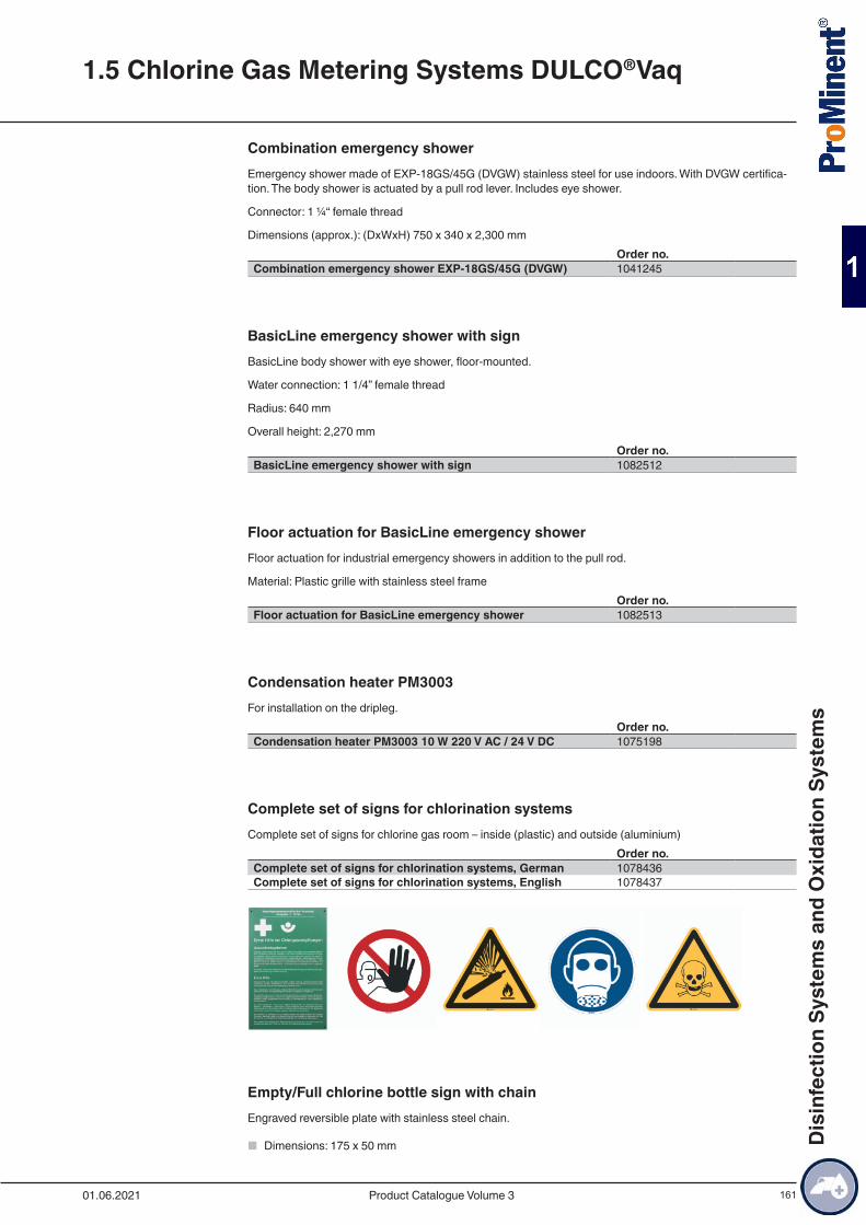
161
Combination emergency showerEmergency shower made of EXP-18GS/45G (DVGW) stainless steel for use indoors. With DVGW certifica-tion. The body shower is actuated by a pull rod lever. Includes eye shower.
Connector: 1 ¼“ female thread
Dimensions (approx.): (DxWxH) 750 x 340 x 2,300 mmOrder no.
Combination emergency shower EXP-18GS/45G (DVGW) 1041245
BasicLine emergency shower with signBasicLine body shower with eye shower, floor-mounted.
Water connection: 1 1/4” female thread
Radius: 640 mm
Overall height: 2,270 mmOrder no.
BasicLine emergency shower with sign 1082512
Floor actuation for BasicLine emergency showerFloor actuation for industrial emergency showers in addition to the pull rod.
Material: Plastic grille with stainless steel frameOrder no.
Floor actuation for BasicLine emergency shower 1082513
Condensation heater PM3003For installation on the dripleg.
Order no.Condensation heater PM3003 10 W 220 V AC / 24 V DC 1075198
Complete set of signs for chlorination systemsComplete set of signs for chlorine gas room – inside (plastic) and outside (aluminium)
Order no.Complete set of signs for chlorination systems, German 1078436Complete set of signs for chlorination systems, English 1078437
Empty/Full chlorine bottle sign with chainEngraved reversible plate with stainless steel chain.
■ Dimensions: 175 x 50 mm
1.5 Chlorine Gas Metering Systems DULCO®Vaq
01.06.2021 Product Catalogue Volume 3
Dis
infe
ctio
n Sy
stem
s an
d O
xida
tion
Syst
ems
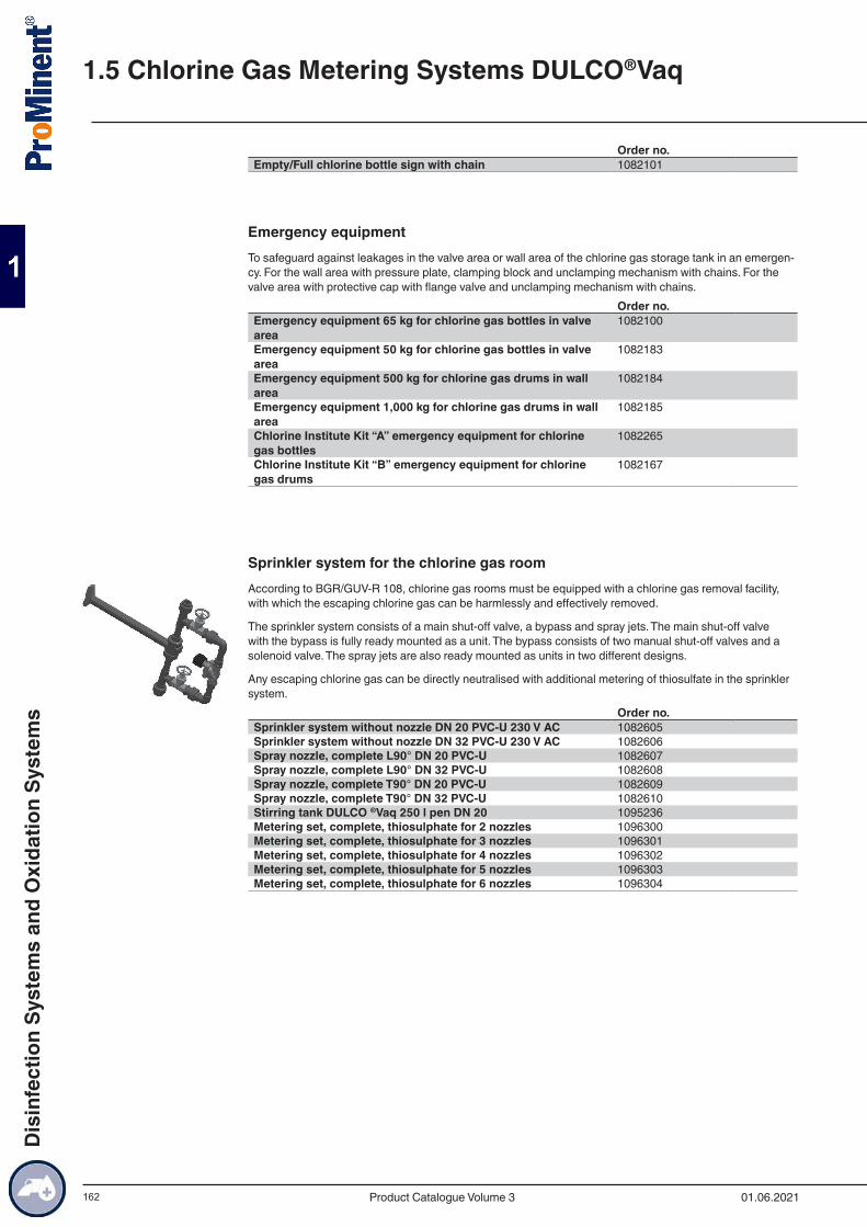
162
Order no.Empty/Full chlorine bottle sign with chain 1082101
Emergency equipmentTo safeguard against leakages in the valve area or wall area of the chlorine gas storage tank in an emergen-cy. For the wall area with pressure plate, clamping block and unclamping mechanism with chains. For the valve area with protective cap with flange valve and unclamping mechanism with chains.
Order no.Emergency equipment 65 kg for chlorine gas bottles in valve area
1082100
Emergency equipment 50 kg for chlorine gas bottles in valve area
1082183
Emergency equipment 500 kg for chlorine gas drums in wall area
1082184
Emergency equipment 1,000 kg for chlorine gas drums in wall area
1082185
Chlorine Institute Kit “A” emergency equipment for chlorine gas bottles
1082265
Chlorine Institute Kit “B” emergency equipment for chlorine gas drums
1082167
Sprinkler system for the chlorine gas roomAccording to BGR/GUV-R 108, chlorine gas rooms must be equipped with a chlorine gas removal facility, with which the escaping chlorine gas can be harmlessly and effectively removed.
The sprinkler system consists of a main shut-off valve, a bypass and spray jets. The main shut-off valve with the bypass is fully ready mounted as a unit. The bypass consists of two manual shut-off valves and a solenoid valve. The spray jets are also ready mounted as units in two different designs.
Any escaping chlorine gas can be directly neutralised with additional metering of thiosulfate in the sprinkler system.
Order no.Sprinkler system without nozzle DN 20 PVC-U 230 V AC 1082605Sprinkler system without nozzle DN 32 PVC-U 230 V AC 1082606Spray nozzle, complete L90° DN 20 PVC-U 1082607Spray nozzle, complete L90° DN 32 PVC-U 1082608Spray nozzle, complete T90° DN 20 PVC-U 1082609Spray nozzle, complete T90° DN 32 PVC-U 1082610Stirring tank DULCO ®Vaq 250 l pen DN 20 1095236Metering set, complete, thiosulphate for 2 nozzles 1096300Metering set, complete, thiosulphate for 3 nozzles 1096301Metering set, complete, thiosulphate for 4 nozzles 1096302Metering set, complete, thiosulphate for 5 nozzles 1096303Metering set, complete, thiosulphate for 6 nozzles 1096304
1.5 Chlorine Gas Metering Systems DULCO®Vaq
01.06.2021Product Catalogue Volume 3
Dis
infe
ctio
n Sy
stem
s an
d O
xida
tion
Syst
ems

163
1.5.18 Other Accessories
Wall fansWall-mounted axial ventilators for ventilation of chlorine gas chamber. DN 500 with quadratic mounting plate and automatic cover flap.Product designation Output Order no. m3/h Wall fan 400 V 50 Hz 5,800 1082412Wall fan 400 V 50 Hz 2,500 1082410Wall fan 400 V 50 Hz 1,150 1082408
Chlorine gas storage tankHigh-grade safety-tested chlorine gas storage tank for use as original equipment or spare part. Supplied empty without chlorine gas.Product designation Volume Order no. l Chlorine gas storage tank P355NL1 EN14208 400 1082164Chlorine gas storage tank P355NL1 EN14208 840 1082165Steel bottle, 35 bar test pressure, standard taper, welded
52 1082133
Weighing systems and drum storageTo monitor and check the liquid level of chlorine gas bottles and drums. Barrel storage for the safe storage and alignment of the chlorine gas drums.
Order no.Electrical bottle scales GR100K-1 1 x 150 kg 1082138Electrical bottle scales GR100K-2 2 x 150 kg 1082139Hydraulic bottle scales 4D100K-1 1 x 150 kg 1082140Hydraulic bottle scales 4D100K-2 2 x 150 kg 1082141Drum scales DR20K 2,000 kg with electronic display 1082136Drum scales DR40K 4,000 kg with electronic display 1082415Drum scales 8D20K 2,000 kg with hydraulic display 1082564Drum scales 8D40K 4,000 kg with hydraulic display 1082565Steel bottle, 35 bar test pressure, standard taper, welded 1082135Drum pallet , galvanised steel 1082166
Crane beam and crane scalesFor the safe transport and loading of chlorine gas drums up to max. 2 tonnes.
Order no.Crane beam for drum length 2,022–2,076 mm steel 1082137Chain hoist HZE020 2,000 kg 3,0 m 1082294Digital crane scales 3,000 kg IP67 230 V SS 1082295Electrical chain hoist 2,000 kg 400 V 50 Hz IP55 1082296Chain container BD4 for 4 m chain length 1082297Cable trolley for power supply, width 132 mm 1082298
Reaction tower with granulated marbleDuring the chlorination of water, hydrochloric acid, which lowers the pH value of the water, is also produced alongside the hypochlorous acid, which has an excellent disinfection effect. If there is insufficient carbonate
1.5 Chlorine Gas Metering Systems DULCO®Vaq
01.06.2021 Product Catalogue Volume 3
Dis
infe
ctio
n Sy
stem
s an
d O
xida
tion
Syst
ems
164
hardness in the water, the buffer capacity is inadequate and can be replaced in the form of reaction towers with granulated marble.
Filter storage tank made of glass fibre-reinforced epoxy resin with a seamless ABS inner liner
■ Operating pressure: max. 10 bar ■ Operating temperature: max. 50 °C ■ Volume: 170 or 310 litres
Order no.Reaction tower HClO 170 l 10 bar epoxy/PE 1082168Reaction tower HClO 310 l 10 bar epoxy/PE 1082169Filter material CaCO3 4.0 – 6.0 mm unit kg 1082544
1.5 Chlorine Gas Metering Systems DULCO®Vaq
01.06.2021Product Catalogue Volume 3
Dis
infe
ctio
n Sy
stem
s an
d O
xida
tion
Syst
ems
165
1.5.19 Personal Safety Equipment
Full face mask Dräger X-Plore 6300Efficient and cost-effective full protection respiratory mask without filter made from EPDM and a viewing panel made from scratchproof PMMA for a 180° wide-angle view.
Order no.Dräger full mask XP 6300 EN136 class 2 1082117
Dräger X-plore breathing filterFor full mask XP 6300. Specifically suitable for use in chlorine gas systems.
Order no.Dräger X-plore breathing filter Rd40 940A2B2 EN143 1082118
Safety bootsWater-tight and slip-resistant.
Order no.Safety boots, yellow size 45 PVC S5 SRA 1082122
Acid apronOrder no.
Acid apron 100 x 120 cm PVC with fabric; black 1082123
Compressed air breathing apparatus, Diablo Rina 1800 Marine
■ Back carrier panel with belt strap carrier ■ Overpressure breathing regulator ■ Pressure reducer with safety valve ■ Manometer ■ Acoustic warning device ■ including full mask C607/SPA (Class 3) with screw connector M45x3 (DIN EN 148-3) ■ including compressed air cylinder (6 l, 300 bar) steel ■ Operating period approx. 45 minutes (1800 l breathing air)
Order no.Compressed air breathing apparatus, Diablo Rina 1800 Marine 1082124
Compressed air cylinderAs replacement cylinder for compressed air breathing apparatus Diablo Rina 1800 (order no. 1082124).
Order no.Compressed air cylinder 6 litres – 300 bar steel 1082173
Protective glovesOrder no.
Protective gloves 640 PVC, Size10 Cat.3 1082126
1.5 Chlorine Gas Metering Systems DULCO®Vaq
01.06.2021 Product Catalogue Volume 3
Dis
infe
ctio
n Sy
stem
s an
d O
xida
tion
Syst
ems
166
Chemical suit VS5 Polyran-LOne-part complete full-body chemical protective suit with fixed visor; gas-tight chemical protective suite with breathing air supply carried in the suit independent of the ambient air, i.e. a storage device with compressed air. Inclusive of gloves and safety boots.
Re-usable, washable, very good mechanical properties (tear-resistant, wear-resistant, puncture-resistant).
Certification: DIN EN 943 Part 1 –1a (Industry)Order no.
Chemical suit VS5 Polyran-L, yellow 1082509
1.5 Chlorine Gas Metering Systems DULCO®Vaq
01.06.2021Product Catalogue Volume 3
Dis
infe
ctio
n Sy
stem
s an
d O
xida
tion
Syst
ems
167
2.1.1 Polyelectrolytes in Water TreatmentThe use of polyelectrolytes as flocculation aids is characterised by an extensive field of applications. They can be used in all applications where colloidal solids need to be economically separated from liquids.
Our preparation and metering systems have been designed specifically for the production of ordinary or standard solutions of synthetic polyelectrolytes in powdered or liquid form and have proved themselves many times over.
The experts in waste water treatment at ProMinent understand how to provide the efficient technology to implement this specialist application. They have developed systems for the most stringent requirements, which are also very easy to assemble and operate.
ProMinent also provides all the advice needed for the efficient operation of a polymer batching and metering system:
■ Evaluation of the situation on site by trained, expert field sales staff. ■ Project planning of the system. ■ Commissioning and system maintenance by our trained service technicians.
2.1 Polymer Preparation and Metering Systems
01.06.2021 Product Catalogue Volume 3
Met
erin
g Sy
stem
s
168
2.1.2 Performance overview of polymer batching and metering systems Ultromat® and PolyRexProMinent offers a wide range of systems for the most diverse batching and metering applications. The following overview shows the capacity ranges of our type series:
Continuous flow system Extraction rate l/h
concentration max. 0.5 %Application Characteristic
ULFa ■ Powder ■ Liquid
400 – 8,000 (maturation time 60 min., starts with batching mode)
■ Potable water treatment ■ Waste water treatment (in-dustry and local authorities) ■ Sludge dewatering
■ Simple screw feeder with good dosing pre-cision proportional to the water supply ■ Functionally simple mixing system with/without wetting cone ■ PP tank, 3-chamber design
Batch preparation stations Extraction rate l/h
concentration max. 0.5 %Application Characteristic
ULDa ■ Powder ■ Liquid
400 – 2,000 (maturation time 60 min., starts with batching mode)
■ Potable water treatment ■ Waste water treatment (in-dustry and local authorities) ■ Sludge dewatering ■ Paper production
■ Simple screw feeder with good dosing pre-cision proportional to the water supply ■ Functionally simple mixing system with/without wetting cone ■ PP tank, double-decker design
PolyRex ■ Powder ■ Liquid
240 – 8,200 (maturation time 45 min., starts after metering)
■ Potable water treatment ■ Waste water treatment (in-dustry and local authorities) ■ Sludge dewatering ■ Paper production
■ Multi-screw feeder with high dosing preci-sion ■ Special flushing system with water ejector for effective powder hydration ■ Stainless steel tanks, double-decker design ■ Integrated Big Bag emptying system
PolyRex Liquid ■ Liquid
1,060 – 3,180 (maturation time 15 min., starts after metering)
■ Waste water treatment (in-dustry and local authorities) ■ Sludge dewatering
■ High-energy mixing ■ Stainless steel tanks
MT ■ Powder
140 – 4,000 ■ Potable water treatment ■ Waste water treatment (in-dustry and local authorities) ■ Sludge dewatering
■ For manual batching operation ■ Ultra-simple mixing system ■ PP tank
In-line preparation station Extraction rate l/h
concentration max. 1.5 %Application Characteristic
ULla ■ Liquid
55 – 2,000 (maturation time 15 min, starts with batching mode)
■ Sludge dewatering and thickening ■ Potable water treatment ■ Waste water treatment (in-dustry and local authorities)
■ Integrated mixing and maturing chamber for fully activated liquid polymer solutions ■ Peristaltic pump and/or metering pumps for the metering of emulsions/dispersions ■ Operator-managed input of the concentra-tion with proportional metering ■ Optional specification of the polymer prepa-ration output
Pendulum system Extraction rate l/h
concentration max. 0.5 %Application Characteristic
ULPa ■ Powder ■ Liquid
400 – 4,000 (maturation time 60 min., starts with batching mode)
■ Potable water treatment ■ Paper production
■ Simple screw feeder with good dosing pre-cision proportional to the water supply ■ Functionally simple mixing system with wetting cone ■ Preparation system using 2 PP tanks
2.1 Polymer Preparation and Metering Systems
01.06.2021Product Catalogue Volume 3
Met
erin
g Sy
stem
s
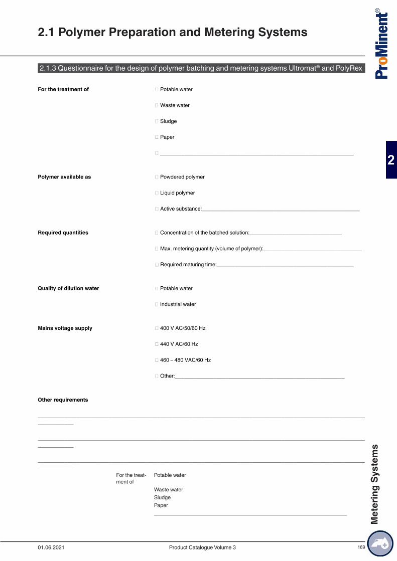
169
2.1.3 Questionnaire for the design of polymer batching and metering systems Ultromat® and PolyRex
For the treatment of � Potable water
� Waste water
� Sludge
� Paper
� _________________________________________________________________
Polymer available as � Powdered polymer
� Liquid polymer
� Active substance:_____________________________________________________
Required quantities � Concentration of the batched solution:_______________________________
� Max. metering quantity (volume of polymer):_________________________________
� Required maturing time:______________________________________________
Quality of dilution water � Potable water
� Industrial water
Mains voltage supply � 400 V AC/50/60 Hz
� 440 V AC/60 Hz
� 460 – 480 VAC/60 Hz
� Other:_________________________________________________________
Other requirements
__________________________________________________________________________________________________________________________
__________________________________________________________________________________________________________________________
__________________________________________________________________________________________________________________________
For the treat-ment of
Potable water
Waste waterSludgePaper_________________________________________________________________
2.1 Polymer Preparation and Metering Systems
01.06.2021 Product Catalogue Volume 3
Met
erin
g Sy
stem
s
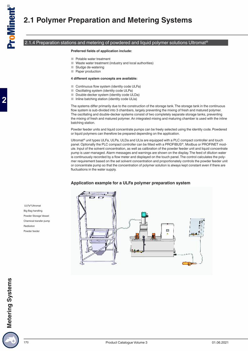
170
2.1.4 Preparation stations and metering of powdered and liquid polymer solutions Ultromat®
Preferred fields of application include:
■ Potable water treatment ■ Waste water treatment (industry and local authorities) ■ Sludge de-watering ■ Paper production
4 different system concepts are available:
■ Continuous flow system (identity code ULFa) ■ Oscillating system (identity code ULPa) ■ Double-decker system (identity code ULDa) ■ Inline batching station (identity code ULIa)
The systems differ primarily due to the construction of the storage tank. The storage tank in the continuous flow system is sub-divided into 3 chambers, largely preventing the mixing of fresh and matured polymer. The oscillating and double-decker systems consist of two completely separate storage tanks, preventing the mixing of fresh and matured polymer. An integrated mixing and maturing chamber is used with the inline batching station.
Powder feeder units and liquid concentrate pumps can be freely selected using the identity code. Powdered or liquid polymers can therefore be prepared depending on the application.
Ultromat® unit types ULFa, ULPa, ULDa and ULIa are equipped with a PLC compact controller and touch panel. Optionally the PLC compact controller can be fitted with a PROFIBUS®, Modbus or PROFINET mod-ule. Input of the solvent concentration, as well as calibration of the powder feeder unit and liquid concentrate pump is user-managed. Alarm messages and warnings are shown on the display. The feed of dilution water is continuously recorded by a flow meter and displayed on the touch panel. The control calculates the poly-mer requirement based on the set solvent concentration and proportionately controls the powder feeder unit or concentrate pump so that the concentration of polymer solution is always kept constant even if there are fluctuations in the water supply.
Application example for a ULFa polymer preparation system
ULFa®Ultromat
Big Bag handling
Powder Storage Vessel
Chemical transfer pump
Redilution
Powder feeder
2.1 Polymer Preparation and Metering Systems
01.06.2021Product Catalogue Volume 3
Met
erin
g Sy
stem
s
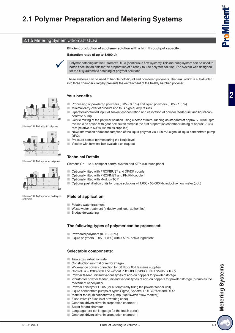
171
2.1.5 Metering System Ultromat® ULFaEfficient production of a polymer solution with a high throughput capacity.
Extraction rates of up to 8,000 l/h
9 Polymer batching station Ultromat® ULFa (continuous flow system): This metering system can be used to batch flocculation aids for the preparation of a ready-to-use polymer solution. The system was designed for the fully automatic batching of polymer solutions.
These systems can be used to handle both liquid and powdered polymers. The tank, which is sub-divided into three chambers, largely prevents the entrainment of the freshly batched polymer.
Your benefits
■ Processing of powdered polymers (0.05 – 0.5 %) and liquid polymers (0.05 – 1.0 %) ■ Minimal carry-over of product and thus high-quality results ■ Operator-controlled input of solvent concentration and calibration of powder feeder unit and liquid con-
centrate pump ■ Gentle mixing of the polymer solution using electric stirrers, running as standard at approx. 700/840 rpm,
available as option with gear box driven stirrer in the first preparation chamber running at approx. 70/84 rpm (relative to 50/60 Hz mains supplies)
■ New: information about consumption of the liquid polymer via 4-20 mA signal of liquid concentrate pump DFXa
■ Pressure sensor for measuring the liquid level ■ Version with terminal box available on request
Technical DetailsSiemens S7 – 1200 compact control system and KTP 400 touch panel
■ Optionally fitted with PROFIBUS® and DP/DP coupler ■ Optionally fitted with PROFINET and PN/PN coupler ■ Optionally fitted with Modbus TCP ■ Optional post dilution units for usage solutions of 1,000 - 50,000 l/h, inductive flow meter (opt.)
Field of application
■ Potable water treatment ■ Waste water treatment (industry and local authorities) ■ Sludge de-watering
The following types of polymer can be processed:
■ Powdered polymers (0.05 - 0.5%) ■ Liquid polymers (0.05 - 1.0 %) with a 50 % active ingredient
Selectable components:
■ Tank size / extraction rate ■ Construction (normal or mirror image) ■ Wide-range power connection for 50 Hz or 60 Hz mains supplies ■ Control S7 – 1200 (with and without PROFIBUS®/PROFINET/Modbus TCP) ■ Powder feeder unit and various types of add-on hoppers for powder storage ■ Vibrator for powder feeder unit and various types of add-on hoppers for powder storage (promotes the
movement of polymer) ■ Powder conveyor FG205 (for automatically filling the powder feeder unit) ■ Liquid concentrate pumps of types Sigma, Spectra, DULCO®flex and DFXa ■ Monitor for liquid concentrate pump (float switch / flow monitor) ■ Flush valve (Y-flush inlet or wetting cone) ■ Gear box driven stirrer in preparation chamber 1 ■ Stirrer for 3rd chamber ■ Language (pre-set language for the touch panel) ■ Gear box driven stirrer in preparation chamber 1
Ultromat® ULFa for liquid polymers
Ultromat® ULFa for powder polymers
Ultromat® ULFa for powder and liquid polymers
2.1 Polymer Preparation and Metering Systems
01.06.2021 Product Catalogue Volume 3
Met
erin
g Sy
stem
s
172
The standard scope of delivery includes among other things:
■ Pause function/operating message/running dry function ■ Preparation operation active message ■ Monitoring of an optional post dilution unit ■ Lifting lugs for transport
2.1 Polymer Preparation and Metering Systems
01.06.2021Product Catalogue Volume 3
Met
erin
g Sy
stem
s
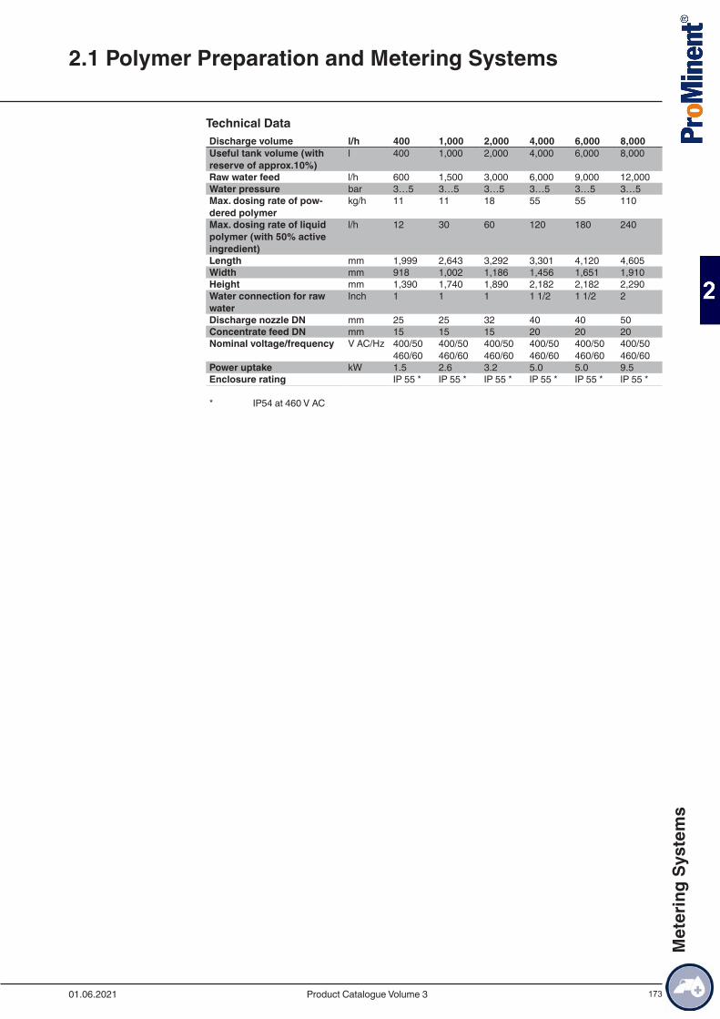
173
Technical DataDischarge volume l/h 400 1,000 2,000 4,000 6,000 8,000Useful tank volume (with reserve of approx.10%)
l 400 1,000 2,000 4,000 6,000 8,000
Raw water feed l/h 600 1,500 3,000 6,000 9,000 12,000Water pressure bar 3…5 3…5 3…5 3…5 3…5 3…5Max. dosing rate of pow-dered polymer
kg/h 11 11 18 55 55 110
Max. dosing rate of liquid polymer (with 50% active ingredient)
l/h 12 30 60 120 180 240
Length mm 1,999 2,643 3,292 3,301 4,120 4,605Width mm 918 1,002 1,186 1,456 1,651 1,910Height mm 1,390 1,740 1,890 2,182 2,182 2,290Water connection for raw water
Inch 1 1 1 1 1/2 1 1/2 2
Discharge nozzle DN mm 25 25 32 40 40 50Concentrate feed DN mm 15 15 15 20 20 20Nominal voltage/frequency V AC/Hz 400/50
460/60400/50 460/60
400/50 460/60
400/50 460/60
400/50 460/60
400/50 460/60
Power uptake kW 1.5 2.6 3.2 5.0 5.0 9.5Enclosure rating IP 55 * IP 55 * IP 55 * IP 55 * IP 55 * IP 55 *
* IP54 at 460 V AC
2.1 Polymer Preparation and Metering Systems
01.06.2021 Product Catalogue Volume 3
Met
erin
g Sy
stem
s
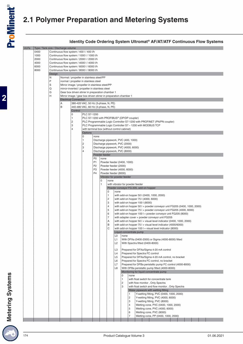
174
Identity Code Ordering System Ultromat® AF/AT/ATF Continuous Flow SystemsULFa Type / Tank size / Discharge volume
0400 Continuous flow system / 400 l / 400 l/h1000 Continuous flow system / 1000 l / 1000 l/h2000 Continuous flow system / 2000 l / 2000 l/h4000 Continuous flow system / 4000 l / 4000 l/h6000 Continuous flow system / 6000 l / 6000 l/h8000 Continuous flow system / 8000 l / 8000 l/h
DesignN Normal / propeller in stainless steel/PPP normal / propeller in stainless steelS Mirror image / propeller in stainless steel/PPQ mirror-inverted / propeller in stainless steelG Gear box driven stirrer in preparation chamber 1H Mirror image / gear box driven stirrer in preparation chamber 1
Electrical ConnectionA 380-420 VAC, 50 Hz (3-phase, N, PE)B 440-480 VAC, 60 Hz (3-phase, N, PE)
Control0 PLC S7-12001 PLC S7-1200 with PROFIBUS® (DP/DP coupler)2 PLC Programmable Logic Controller S7-1200 with PROFINET (PN/PN coupler)3 PLC Programmable Logic Controller S7 – 1200 with MODBUS TCP4 with terminal box (without control cabinet)
Options0 none1 Discharge pipework, PVC (400, 1000)2 Discharge pipework, PVC (2000)3 Discharge pipework, PVC (4000, 6000)4 Discharge pipework, PVC (8000)
Powder feederP0 noneP1 Powder feeder (0400, 1000)P2 Powder feeder (2000)P3 Powder feeder (4000, 6000)P4 Powder feeder (8000)
Vibrator for powder feeder0 none1 with vibrator for powder feeder
Powder conveyor FG 205, add-on hopper0 none1 with add-on hopper 50 l (0400, 1000, 2000)2 with add-on hopper 75 l (4000, 6000)3 with add-on hopper 100 l (8000)4 with add-on hopper 50 l + powder conveyor unit FG205 (0400, 1000, 2000)5 with add-on hopper 75 l + powder conveyor unit FG205 (4000, 6000)6 with add-on hopper 100 l + powder conveyor unit FG205 (8000)7 with adapter cover + powder conveyor unit FG205A with add-on hopper 50 l + visual level indicator (0400, 1000, 2000)B with add-on hopper 75 l + visual level indicator (4000/6000)C with add-on hopper 100 l + visual level indicator (8000)
Liquid concentrate pumpL0 noneL1 With DFXa (0400-2000) or Sigma (4000-8000) fittedL2 With Spectra fitted (0400-8000)
L3 Prepared for DFXa/Sigma 4-20 mA controlL4 Prepared for Spectra FC controlL5 Prepared for DFXa/Sigma 4-20 mA control, no bracketL6 Prepared for Spectra FC control, no bracketL7 Prepared for DFBa peristaltic pump FC control (4000-8000)L8 With DFBa peristaltic pump fitted (4000-8000)
Monitoring for liquid concentrate pump0 none1 with float switch for concentrate tank2 with flow monitor , Only Spectra3 with float switch and flow monitor , Only Spectra
Water pipework with wetting fitting1 Y-wetting fitting, PVC (0400, 1000, 2000)2 Y-wetting fitting, PVC (4000, 6000)3 Y-wetting fitting, PVC (8000)4 Wetting cone, PVC (0400, 1000, 2000)5 Wetting cone, PVC (4000, 6000)6 Wetting cone, PVC (8000)7 Wetting cone, PP (0400, 1000, 2000)
2.1 Polymer Preparation and Metering Systems
01.06.2021Product Catalogue Volume 3
Met
erin
g Sy
stem
s
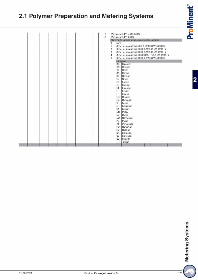
175
8 Wetting cone, PP (4000, 6000)9 Wetting cone, PP (8000)
Stirrer for 3<superscript>rd</superscript> chamber0 none1 Stirrer for storage tank 400, 0.18/0.25 kW, 50/60 Hz2 Stirrer for storage tank 1000, 0.55/0.68 kW, 50/60 Hz3 Stirrer for storage tank 2000, 0.75/0.86 kW, 50/60 Hz4 Stirrer for storage tank 4000/6000, 1.1/1.3 kW, 50/60 Hz5 Stirrer for storage tank 8000, 2.2/2.55 kW, 50/60 Hz
LanguageBG BulgarianCN ChineseCZ CzechDA DanishDE GermanEL GreekEN EnglishES SpanishET EstonianFI FinnishFR FrenchHR CroatianHU HungarianIT ItalianLT LithuanianLV LatvianMS MalayNL DutchNO NorwegianPL PolishPT PortugueseRO RomanianRU RussianSK SlovakianSL SlovenianSV SwedishTR Turkish
2.1 Polymer Preparation and Metering Systems
01.06.2021 Product Catalogue Volume 3
Met
erin
g Sy
stem
s
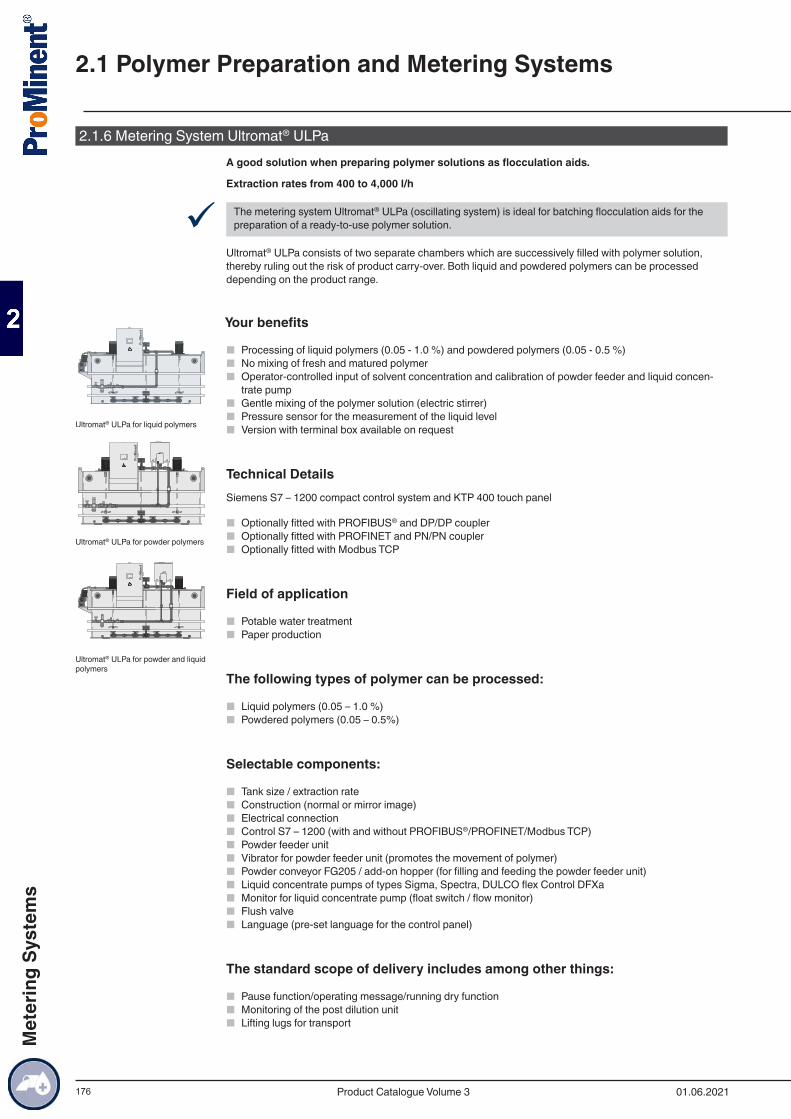
176
2.1.6 Metering System Ultromat® ULPaA good solution when preparing polymer solutions as flocculation aids.
Extraction rates from 400 to 4,000 l/h
9 The metering system Ultromat® ULPa (oscillating system) is ideal for batching flocculation aids for the preparation of a ready-to-use polymer solution.
Ultromat® ULPa consists of two separate chambers which are successively filled with polymer solution, thereby ruling out the risk of product carry-over. Both liquid and powdered polymers can be processed depending on the product range.
Your benefits
■ Processing of liquid polymers (0.05 - 1.0 %) and powdered polymers (0.05 - 0.5 %) ■ No mixing of fresh and matured polymer ■ Operator-controlled input of solvent concentration and calibration of powder feeder and liquid concen-
trate pump ■ Gentle mixing of the polymer solution (electric stirrer) ■ Pressure sensor for the measurement of the liquid level ■ Version with terminal box available on request
Technical DetailsSiemens S7 – 1200 compact control system and KTP 400 touch panel
■ Optionally fitted with PROFIBUS® and DP/DP coupler ■ Optionally fitted with PROFINET and PN/PN coupler ■ Optionally fitted with Modbus TCP
Field of application
■ Potable water treatment ■ Paper production
The following types of polymer can be processed:
■ Liquid polymers (0.05 – 1.0 %) ■ Powdered polymers (0.05 – 0.5%)
Selectable components:
■ Tank size / extraction rate ■ Construction (normal or mirror image) ■ Electrical connection ■ Control S7 – 1200 (with and without PROFIBUS®/PROFINET/Modbus TCP) ■ Powder feeder unit ■ Vibrator for powder feeder unit (promotes the movement of polymer) ■ Powder conveyor FG205 / add-on hopper (for filling and feeding the powder feeder unit) ■ Liquid concentrate pumps of types Sigma, Spectra, DULCO flex Control DFXa ■ Monitor for liquid concentrate pump (float switch / flow monitor) ■ Flush valve ■ Language (pre-set language for the control panel)
The standard scope of delivery includes among other things:
■ Pause function/operating message/running dry function ■ Monitoring of the post dilution unit ■ Lifting lugs for transport
Ultromat® ULPa for liquid polymers
Ultromat® ULPa for powder polymers
Ultromat® ULPa for powder and liquid polymers
2.1 Polymer Preparation and Metering Systems
01.06.2021Product Catalogue Volume 3
Met
erin
g Sy
stem
s
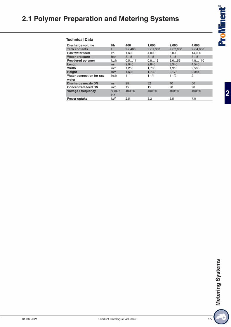
177
Technical DataDischarge volume l/h 400 1,000 2,000 4,000Tank contents l 2 x 400 2 x 1,000 2 x 2,000 2 x 4,000Raw water feed l/h 1,600 4,000 8,000 14,000Water pressure bar 3…5 3…5 3…5 3…5Powdered polymer kg/h 0.5…11 0.8…18 3.6…55 4.8…110Length mm 2,040 2,840 3,340 4,540Width mm 1,253 1,733 1,918 2,583Height mm 1,635 1,739 2,178 2,384Water connection for raw water
Inch 1 1 1/4 1 1/2 2
Discharge nozzle DN mm 25 32 40 50Concentrate feed DN mm 15 15 20 20Voltage / frequency V AC /
Hz400/50 400/50 400/50 400/50
Power uptake kW 2.5 3.2 5.5 7.0
2.1 Polymer Preparation and Metering Systems
01.06.2021 Product Catalogue Volume 3
Met
erin
g Sy
stem
s
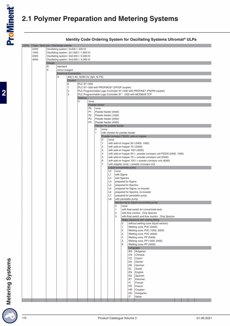
178
Identity Code Ordering System for Oscillating Systems Ultromat® ULPaULPa Type / Tank size / Discharge volume
0400 Oscillating system / 2x400 l / 400 l/h1000 Oscillating system / 2x1,000 l / 1,000 l/h2000 Oscillating system / 2x2,000 l / 2,000 l/h4000 Oscillating system / 2x4,000 l / 4,000 l/h
DesignN standardS mirror-imaged
Electrical ConnectionA 400 V AC, 50/60 Hz (3ph, N, PE)
Control0 PLC S7-12001 PLC S7-1200 with PROFIBUS® (DP/DP coupler)2 PLC Programmable Logic Controller S7-1200 with PROFINET (PN/PN coupler)3 PLC Programmable Logic Controller S7 – 1200 with MODBUS TCP
Options0 none
Powder feederP0 noneP1 Powder feeder (0400)P2 Powder feeder (1000)P3 Powder feeder (2000)P4 Powder feeder (4000)
Vibrator for powder feeder0 none1 with vibrator for powder feeder
Powder conveyor FG205, add-on hopper0 none1 with add-on hopper 50 l (0400, 1000)2 with add-on hopper 75 l (2000)3 with add-on hopper 100 l (4000)4 with add-on hopper 50 l + powder conveyor unit FG205 (0400, 1000)5 with add-on hopper 75 l + powder conveyor unit (2000)6 with add-on hopper 100 l + powder conveyor unit (4000)7 with adapter cover + powder conveyor unit
Liquid concentrate pumpL0 noneL1 with SigmaL2 with SpectraL3 prepared for SigmaL4 prepared for SpectraL5 prepared for Sigma, no bracketL6 prepared for Spectra, no bracketL7 prepared for peristaltic pumpL8 with peristaltic pump
Monitoring for liquid concentrate pump0 none1 with float switch for concentrate tank2 with flow monitor , Only Spectra3 with float switch and flow monitor , Only Spectra
Water pipework with wetting fitting0 without wetting cone (liquid version)1 Wetting cone, PVC (0400)2 Wetting cone, PVC (1000, 2000)3 Wetting cone, PVC (4000)4 Wetting cone, PP (0400)5 Wetting cone, PP (1000, 2000)6 Wetting cone, PP (4000)
LanguageBG BulgarianCN ChineseCZ CzechDA DanishDE GermanEL GreekEN EnglishES SpanishET EstonianFI FinnishFR FrenchHR CroatianHU HungarianIT Italian
2.1 Polymer Preparation and Metering Systems
01.06.2021Product Catalogue Volume 3
Met
erin
g Sy
stem
s
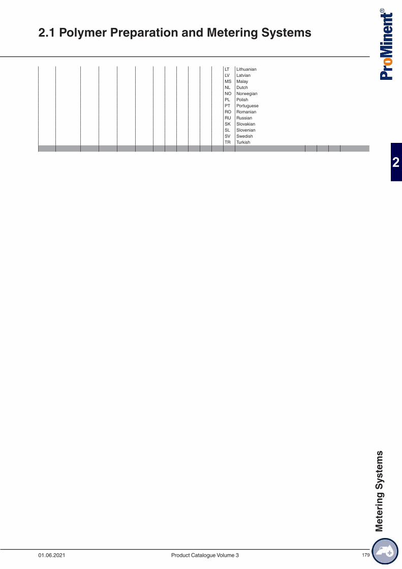
179
LT LithuanianLV LatvianMS MalayNL DutchNO NorwegianPL PolishPT PortugueseRO RomanianRU RussianSK SlovakianSL SlovenianSV SwedishTR Turkish
2.1 Polymer Preparation and Metering Systems
01.06.2021 Product Catalogue Volume 3
Met
erin
g Sy
stem
s
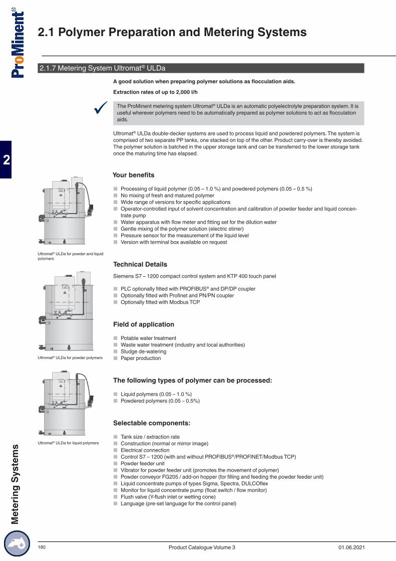
180
2.1.7 Metering System Ultromat® ULDaA good solution when preparing polymer solutions as flocculation aids.
Extraction rates of up to 2,000 l/h
9 The ProMinent metering system Ultromat® ULDa is an automatic polyelectrolyte preparation system. It is useful wherever polymers need to be automatically prepared as polymer solutions to act as flocculation aids.
Ultromat® ULDa double-decker systems are used to process liquid and powdered polymers. The system is comprised of two separate PP tanks, one stacked on top of the other. Product carry-over is thereby avoided. The polymer solution is batched in the upper storage tank and can be transferred to the lower storage tank once the maturing time has elapsed.
Your benefits
■ Processing of liquid polymer (0.05 – 1.0 %) and powdered polymers (0.05 – 0.5 %) ■ No mixing of fresh and matured polymer ■ Wide range of versions for specific applications ■ Operator-controlled input of solvent concentration and calibration of powder feeder and liquid concen-
trate pump ■ Water apparatus with flow meter and fitting set for the dilution water ■ Gentle mixing of the polymer solution (electric stirrer) ■ Pressure sensor for the measurement of the liquid level ■ Version with terminal box available on request
Technical DetailsSiemens S7 – 1200 compact control system and KTP 400 touch panel
■ PLC optionally fitted with PROFIBUS® and DP/DP coupler ■ Optionally fitted with Profinet and PN/PN coupler ■ Optionally fitted with Modbus TCP
Field of application
■ Potable water treatment ■ Waste water treatment (industry and local authorities) ■ Sludge de-watering ■ Paper production
The following types of polymer can be processed:
■ Liquid polymers (0.05 – 1.0 %) ■ Powdered polymers (0.05 – 0.5%)
Selectable components:
■ Tank size / extraction rate ■ Construction (normal or mirror image) ■ Electrical connection ■ Control S7 – 1200 (with and without PROFIBUS®/PROFINET/Modbus TCP) ■ Powder feeder unit ■ Vibrator for powder feeder unit (promotes the movement of polymer) ■ Powder conveyor FG205 / add-on hopper (for filling and feeding the powder feeder unit) ■ Liquid concentrate pumps of types Sigma, Spectra, DULCOflex ■ Monitor for liquid concentrate pump (float switch / flow monitor) ■ Flush valve (Y-flush inlet or wetting cone) ■ Language (pre-set language for the control panel)
Ultromat® ULDa for powder and liquid polymers
Ultromat® ULDa for powder polymers
Ultromat® ULDa for liquid polymers
2.1 Polymer Preparation and Metering Systems
01.06.2021Product Catalogue Volume 3
Met
erin
g Sy
stem
s
181
The standard scope of delivery includes among other things:
■ Pause function/operating message/running dry function ■ Monitoring of the post dilution unit ■ Lifting lugs
2.1 Polymer Preparation and Metering Systems
01.06.2021 Product Catalogue Volume 3
Met
erin
g Sy
stem
s
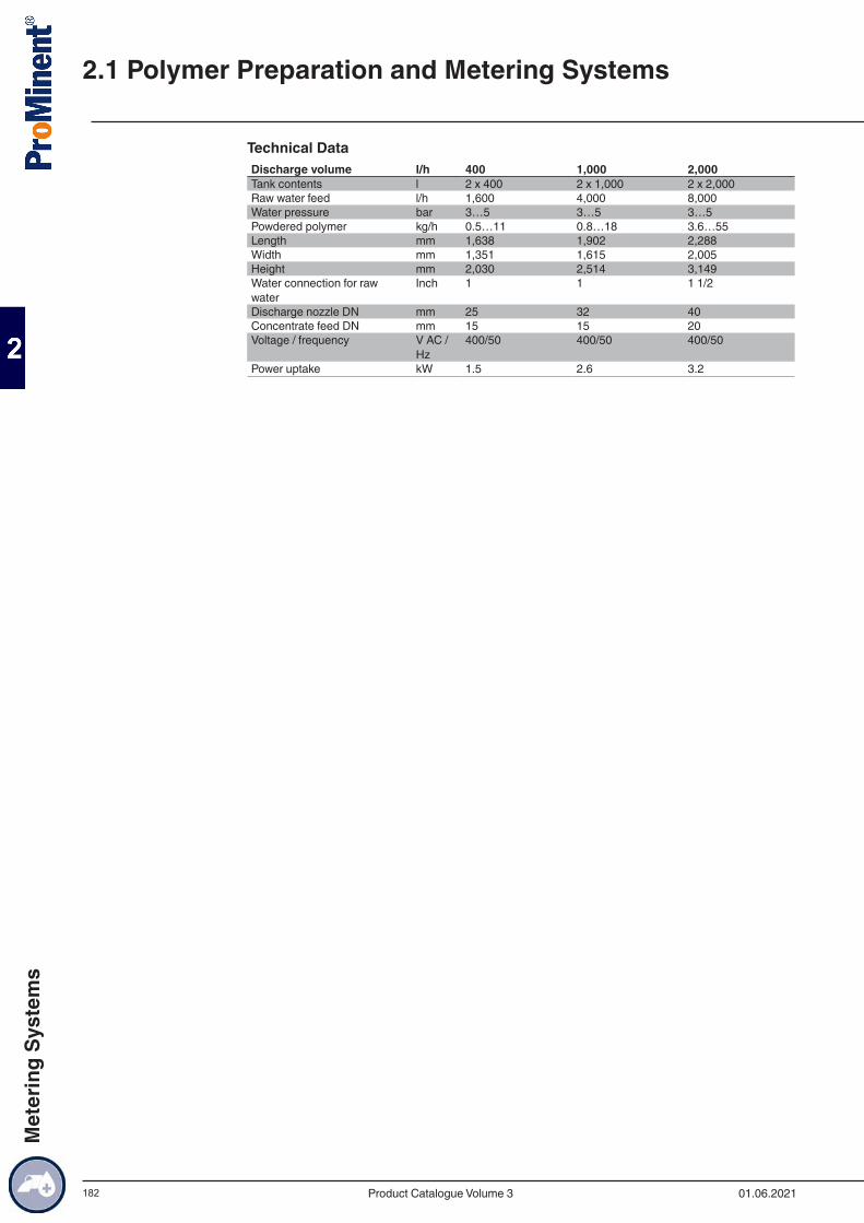
182
Technical DataDischarge volume l/h 400 1,000 2,000Tank contents l 2 x 400 2 x 1,000 2 x 2,000Raw water feed l/h 1,600 4,000 8,000Water pressure bar 3…5 3…5 3…5Powdered polymer kg/h 0.5…11 0.8…18 3.6…55Length mm 1,638 1,902 2,288Width mm 1,351 1,615 2,005Height mm 2,030 2,514 3,149Water connection for raw water
Inch 1 1 1 1/2
Discharge nozzle DN mm 25 32 40Concentrate feed DN mm 15 15 20Voltage / frequency V AC /
Hz400/50 400/50 400/50
Power uptake kW 1.5 2.6 3.2
2.1 Polymer Preparation and Metering Systems
01.06.2021Product Catalogue Volume 3
Met
erin
g Sy
stem
s
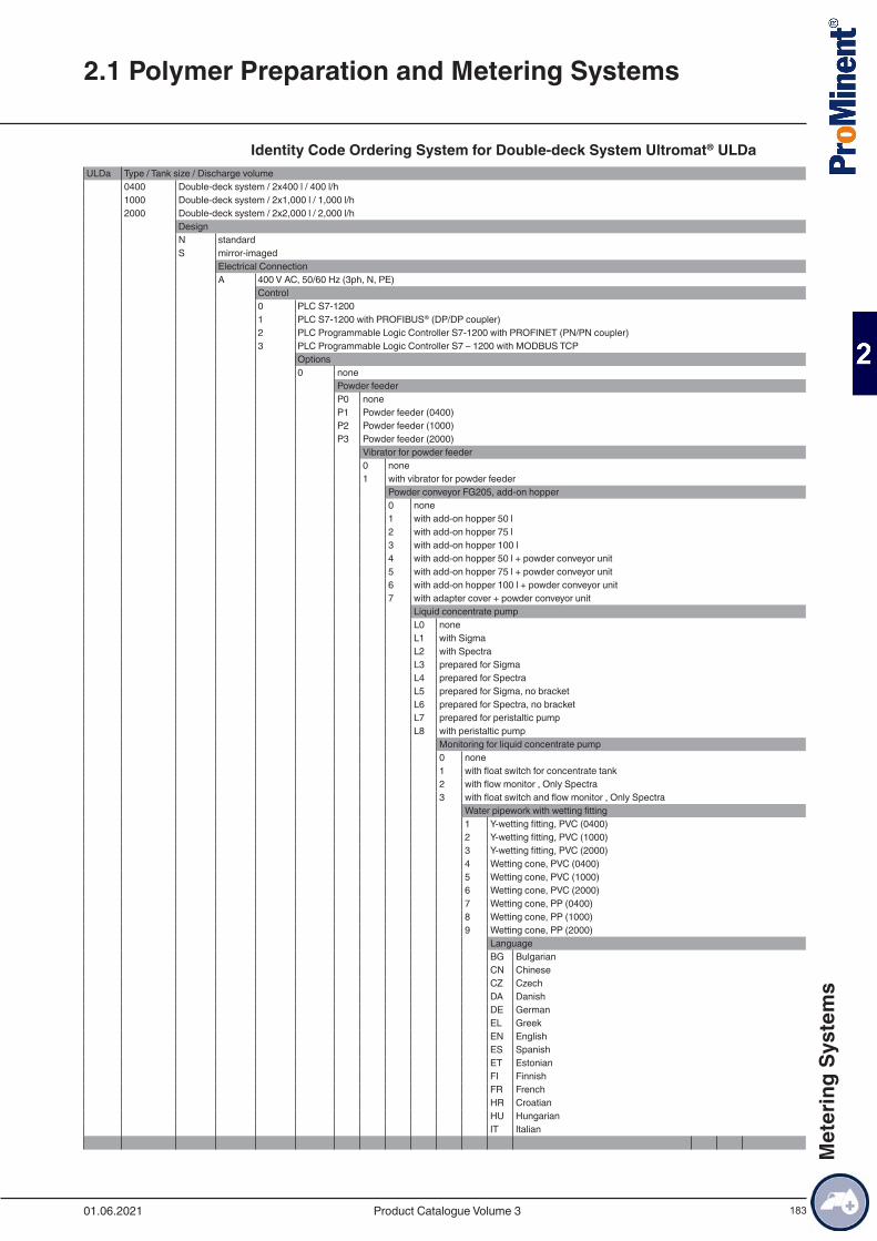
183
Identity Code Ordering System for Double-deck System Ultromat® ULDaULDa Type / Tank size / Discharge volume
0400 Double-deck system / 2x400 l / 400 l/h1000 Double-deck system / 2x1,000 l / 1,000 l/h2000 Double-deck system / 2x2,000 l / 2,000 l/h
DesignN standardS mirror-imaged
Electrical ConnectionA 400 V AC, 50/60 Hz (3ph, N, PE)
Control0 PLC S7-12001 PLC S7-1200 with PROFIBUS® (DP/DP coupler)2 PLC Programmable Logic Controller S7-1200 with PROFINET (PN/PN coupler)3 PLC Programmable Logic Controller S7 – 1200 with MODBUS TCP
Options0 none
Powder feederP0 noneP1 Powder feeder (0400)P2 Powder feeder (1000)P3 Powder feeder (2000)
Vibrator for powder feeder0 none1 with vibrator for powder feeder
Powder conveyor FG205, add-on hopper0 none1 with add-on hopper 50 l2 with add-on hopper 75 l3 with add-on hopper 100 l4 with add-on hopper 50 l + powder conveyor unit5 with add-on hopper 75 l + powder conveyor unit6 with add-on hopper 100 l + powder conveyor unit7 with adapter cover + powder conveyor unit
Liquid concentrate pumpL0 noneL1 with SigmaL2 with SpectraL3 prepared for SigmaL4 prepared for SpectraL5 prepared for Sigma, no bracketL6 prepared for Spectra, no bracketL7 prepared for peristaltic pumpL8 with peristaltic pump
Monitoring for liquid concentrate pump0 none1 with float switch for concentrate tank2 with flow monitor , Only Spectra3 with float switch and flow monitor , Only Spectra
Water pipework with wetting fitting1 Y-wetting fitting, PVC (0400)2 Y-wetting fitting, PVC (1000)3 Y-wetting fitting, PVC (2000)4 Wetting cone, PVC (0400)5 Wetting cone, PVC (1000)6 Wetting cone, PVC (2000)7 Wetting cone, PP (0400)8 Wetting cone, PP (1000)9 Wetting cone, PP (2000)
LanguageBG BulgarianCN ChineseCZ CzechDA DanishDE GermanEL GreekEN EnglishES SpanishET EstonianFI FinnishFR FrenchHR CroatianHU HungarianIT Italian
2.1 Polymer Preparation and Metering Systems
01.06.2021 Product Catalogue Volume 3
Met
erin
g Sy
stem
s
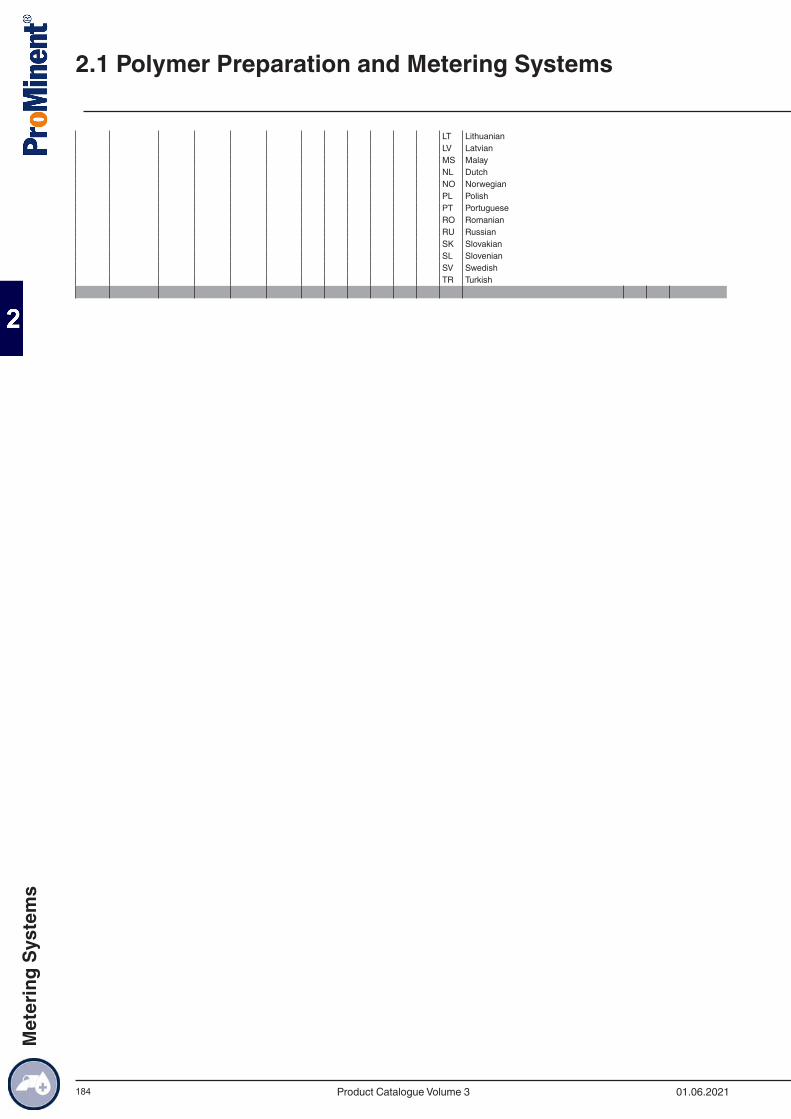
184
LT LithuanianLV LatvianMS MalayNL DutchNO NorwegianPL PolishPT PortugueseRO RomanianRU RussianSK SlovakianSL SlovenianSV SwedishTR Turkish
2.1 Polymer Preparation and Metering Systems
01.06.2021Product Catalogue Volume 3
Met
erin
g Sy
stem
s
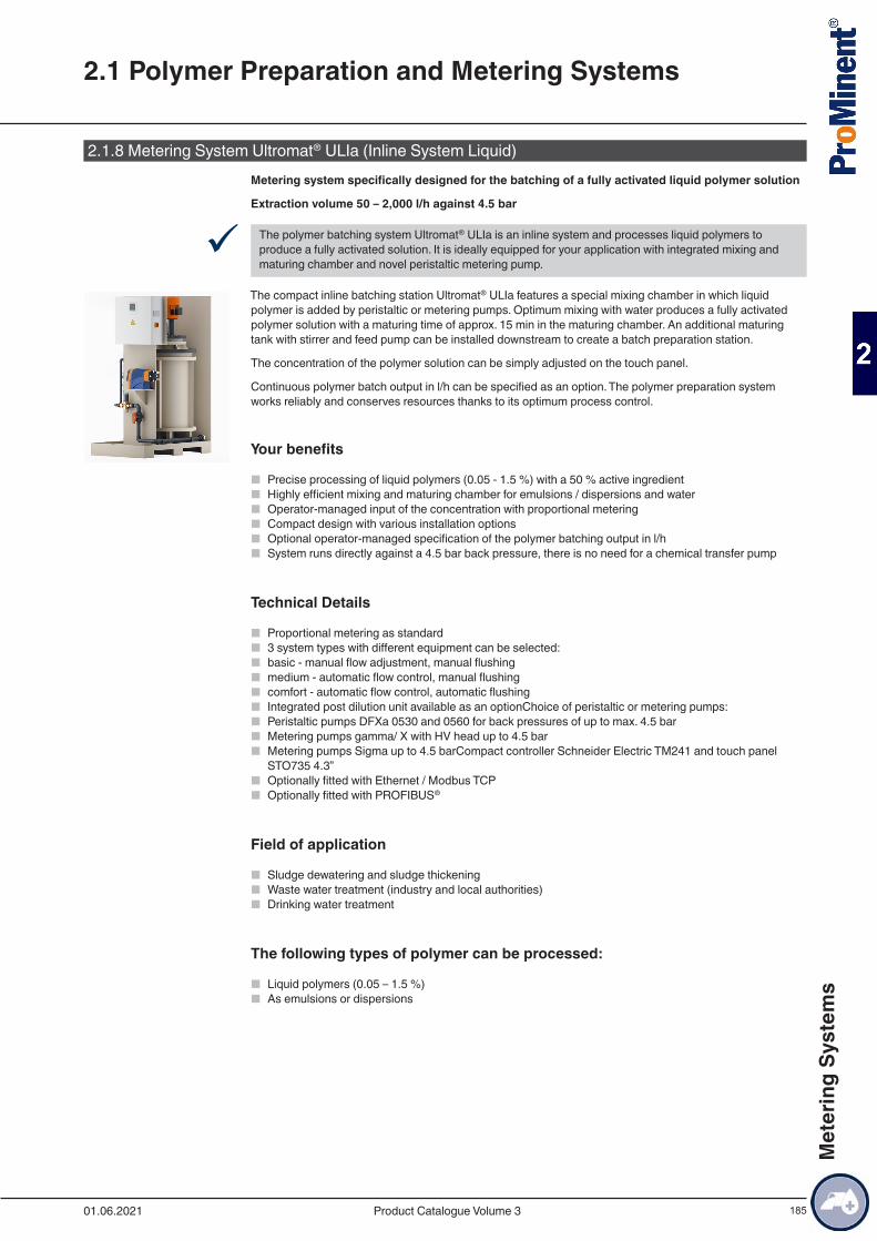
185
2.1.8 Metering System Ultromat® ULIa (Inline System Liquid)Metering system specifically designed for the batching of a fully activated liquid polymer solution
Extraction volume 50 – 2,000 l/h against 4.5 bar
9 The polymer batching system Ultromat® ULIa is an inline system and processes liquid polymers to produce a fully activated solution. It is ideally equipped for your application with integrated mixing and maturing chamber and novel peristaltic metering pump.
The compact inline batching station Ultromat® ULIa features a special mixing chamber in which liquid polymer is added by peristaltic or metering pumps. Optimum mixing with water produces a fully activated polymer solution with a maturing time of approx. 15 min in the maturing chamber. An additional maturing tank with stirrer and feed pump can be installed downstream to create a batch preparation station.
The concentration of the polymer solution can be simply adjusted on the touch panel.
Continuous polymer batch output in l/h can be specified as an option. The polymer preparation system works reliably and conserves resources thanks to its optimum process control.
Your benefits
■ Precise processing of liquid polymers (0.05 - 1.5 %) with a 50 % active ingredient ■ Highly efficient mixing and maturing chamber for emulsions / dispersions and water ■ Operator-managed input of the concentration with proportional metering ■ Compact design with various installation options ■ Optional operator-managed specification of the polymer batching output in l/h ■ System runs directly against a 4.5 bar back pressure, there is no need for a chemical transfer pump
Technical Details
■ Proportional metering as standard ■ 3 system types with different equipment can be selected: ■ basic - manual flow adjustment, manual flushing ■ medium - automatic flow control, manual flushing ■ comfort - automatic flow control, automatic flushing ■ Integrated post dilution unit available as an optionChoice of peristaltic or metering pumps: ■ Peristaltic pumps DFXa 0530 and 0560 for back pressures of up to max. 4.5 bar ■ Metering pumps gamma/ X with HV head up to 4.5 bar ■ Metering pumps Sigma up to 4.5 barCompact controller Schneider Electric TM241 and touch panel
STO735 4.3” ■ Optionally fitted with Ethernet / Modbus TCP ■ Optionally fitted with PROFIBUS®
Field of application
■ Sludge dewatering and sludge thickening ■ Waste water treatment (industry and local authorities) ■ Drinking water treatment
The following types of polymer can be processed:
■ Liquid polymers (0.05 – 1.5 %) ■ As emulsions or dispersions
2.1 Polymer Preparation and Metering Systems
01.06.2021 Product Catalogue Volume 3
Met
erin
g Sy
stem
s
186
Selectable components:
■ Batching output as an inline batching station or batch preparation station ■ Configuration versions ■ Electrical connection ■ Control versions with or without data communication ■ Operating versions ■ Liquid polymer metering pumps
■ Peristaltic pump DFXa ■ Metering pump gamma/ X ■ Metering pump Sigma 1 Control
■ Monitoring of low liquid polymers ■ Raw water booster pump ■ Post dilution unit ■ Additional maturing tank with stirrer for batch preparation ■ Feed pump for additional maturing storage tank ■ Language
2.1 Polymer Preparation and Metering Systems
01.06.2021Product Catalogue Volume 3
Met
erin
g Sy
stem
s
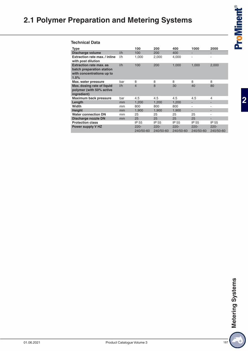
187
Technical DataType 100 200 400 1000 2000Discharge volume l/h 100 200 400 - -Extraction rate max. / inline with post dilution
l/h 1,000 2,000 4,000 - -
Extraction rate max. as batch preparation station with concentrations up to 1.5%
l/h 100 200 1,000 1,000 2,000
Max. water pressure bar 8 8 8 8 8Max. dosing rate of liquid polymer (with 50% active ingredient)
l/h 4 8 30 40 80
Maximum back pressure bar 4.5 4.5 4.5 4.5 4Length mm 1,200 1,200 1,200 - -Width mm 800 800 800 - -Height mm 1,900 1,900 1,900 - -Water connection DN mm 25 25 25 25 -Discharge nozzle DN mm 25 25 25 25 -Protection class IP 55 IP 55 IP 55 IP 55 IP 55Power supply V HZ 220-
240/50-60220-240/50-60
220-240/50-60
220-240/50-60
220-240/50-60
2.1 Polymer Preparation and Metering Systems
01.06.2021 Product Catalogue Volume 3
Met
erin
g Sy
stem
s
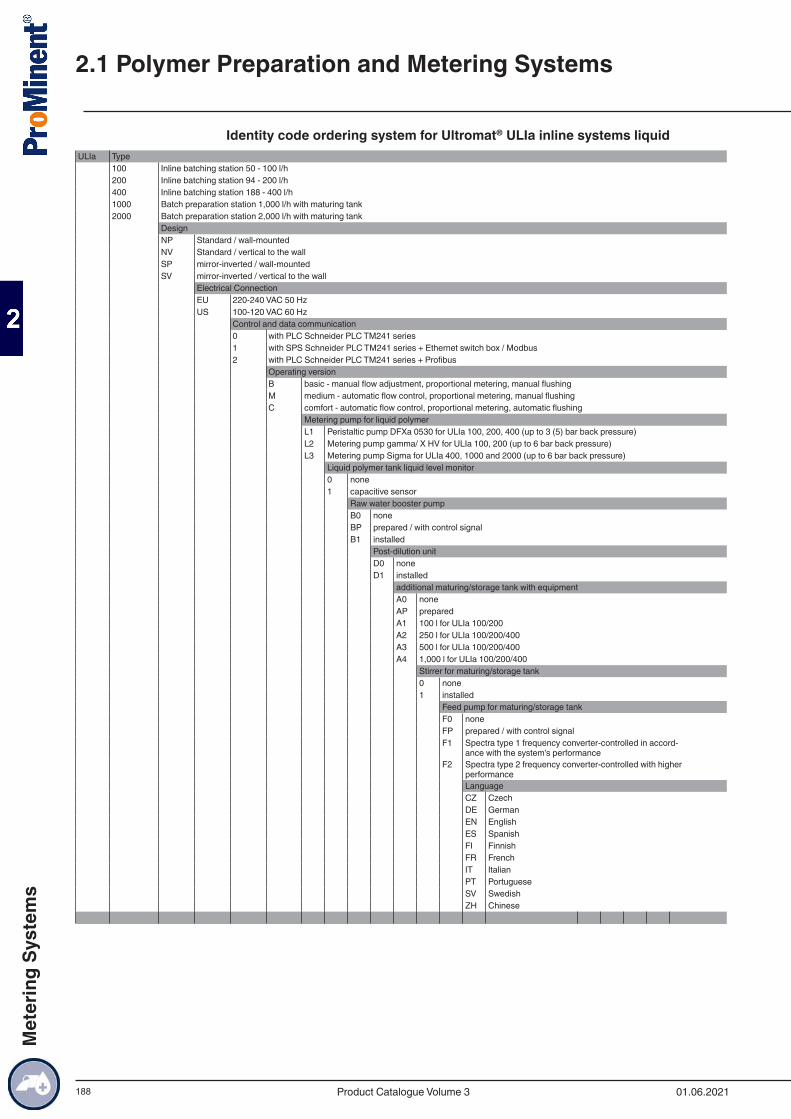
188
Identity code ordering system for Ultromat® ULIa inline systems liquidULIa Type
100 Inline batching station 50 - 100 l/h200 Inline batching station 94 - 200 l/h400 Inline batching station 188 - 400 l/h1000 Batch preparation station 1,000 l/h with maturing tank2000 Batch preparation station 2,000 l/h with maturing tank
DesignNP Standard / wall-mountedNV Standard / vertical to the wallSP mirror-inverted / wall-mountedSV mirror-inverted / vertical to the wall
Electrical ConnectionEU 220-240 VAC 50 HzUS 100-120 VAC 60 Hz
Control and data communication0 with PLC Schneider PLC TM241 series1 with SPS Schneider PLC TM241 series + Ethernet switch box / Modbus2 with PLC Schneider PLC TM241 series + Profibus
Operating versionB basic - manual flow adjustment, proportional metering, manual flushingM medium - automatic flow control, proportional metering, manual flushingC comfort - automatic flow control, proportional metering, automatic flushing
Metering pump for liquid polymerL1 Peristaltic pump DFXa 0530 for ULIa 100, 200, 400 (up to 3 (5) bar back pressure)L2 Metering pump gamma/ X HV for ULIa 100, 200 (up to 6 bar back pressure)L3 Metering pump Sigma for ULIa 400, 1000 and 2000 (up to 6 bar back pressure)
Liquid polymer tank liquid level monitor0 none1 capacitive sensor
Raw water booster pumpB0 noneBP prepared / with control signalB1 installed
Post-dilution unitD0 noneD1 installed
additional maturing/storage tank with equipmentA0 noneAP preparedA1 100 l for ULIa 100/200A2 250 l for ULIa 100/200/400A3 500 l for ULIa 100/200/400A4 1,000 l for ULIa 100/200/400
Stirrer for maturing/storage tank0 none1 installed
Feed pump for maturing/storage tankF0 noneFP prepared / with control signalF1 Spectra type 1 frequency converter-controlled in accord-
ance with the system’s performanceF2 Spectra type 2 frequency converter-controlled with higher
performanceLanguageCZ CzechDE GermanEN EnglishES SpanishFI FinnishFR FrenchIT ItalianPT PortugueseSV SwedishZH Chinese
2.1 Polymer Preparation and Metering Systems
01.06.2021Product Catalogue Volume 3
Met
erin
g Sy
stem
s
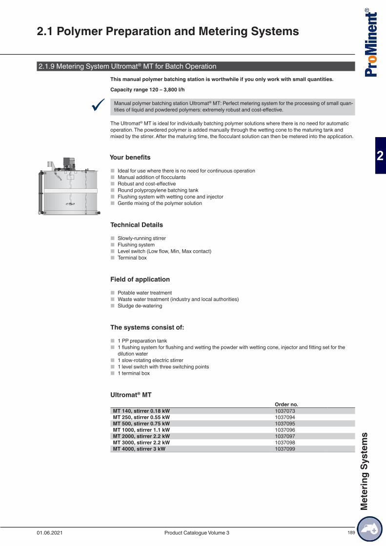
189
2.1.9 Metering System Ultromat® MT for Batch OperationThis manual polymer batching station is worthwhile if you only work with small quantities.
Capacity range 120 – 3,800 l/h
9 Manual polymer batching station Ultromat® MT: Perfect metering system for the processing of small quan-tities of liquid and powdered polymers: extremely robust and cost-effective.
The Ultromat® MT is ideal for individually batching polymer solutions where there is no need for automatic operation. The powdered polymer is added manually through the wetting cone to the maturing tank and mixed by the stirrer. After the maturing time, the flocculant solution can then be metered into the application.
Your benefits
■ Ideal for use where there is no need for continuous operation ■ Manual addition of flocculants ■ Robust and cost-effective ■ Round polypropylene batching tank ■ Flushing system with wetting cone and injector ■ Gentle mixing of the polymer solution
Technical Details
■ Slowly-running stirrer ■ Flushing system ■ Level switch (Low flow, Min, Max contact) ■ Terminal box
Field of application
■ Potable water treatment ■ Waste water treatment (industry and local authorities) ■ Sludge de-watering
The systems consist of:
■ 1 PP preparation tank ■ 1 flushing system for flushing and wetting the powder with wetting cone, injector and fitting set for the
dilution water ■ 1 slow-rotating electric stirrer ■ 1 level switch with three switching points ■ 1 terminal box
Ultromat® MTOrder no.
MT 140, stirrer 0.18 kW 1037073MT 250, stirrer 0.55 kW 1037094MT 500, stirrer 0.75 kW 1037095MT 1000, stirrer 1.1 kW 1037096MT 2000, stirrer 2.2 kW 1037097MT 3000, stirrer 2.2 kW 1037098MT 4000, stirrer 3 kW 1037099
2.1 Polymer Preparation and Metering Systems
01.06.2021 Product Catalogue Volume 3
Met
erin
g Sy
stem
s
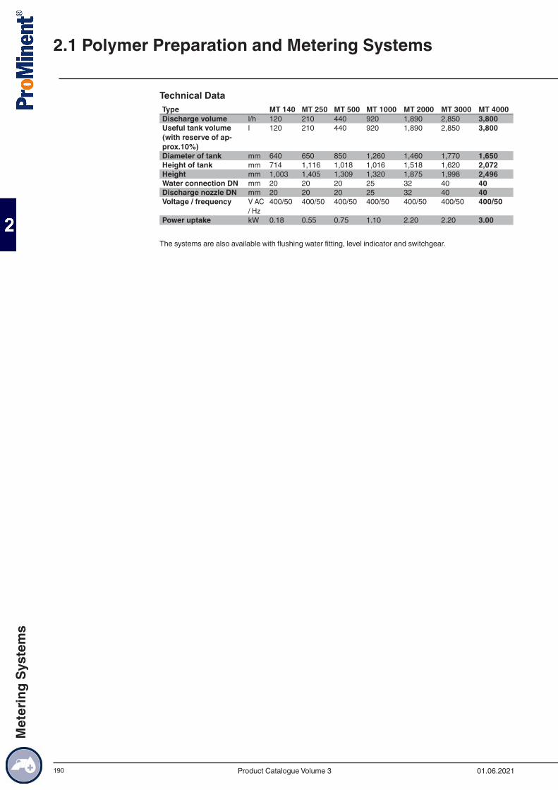
190
Technical DataType MT 140 MT 250 MT 500 MT 1000 MT 2000 MT 3000 MT 4000Discharge volume l/h 120 210 440 920 1,890 2,850 3,800Useful tank volume (with reserve of ap-prox.10%)
l 120 210 440 920 1,890 2,850 3,800
Diameter of tank mm 640 650 850 1,260 1,460 1,770 1,650Height of tank mm 714 1,116 1,018 1,016 1,518 1,620 2,072Height mm 1,003 1,405 1,309 1,320 1,875 1,998 2,496Water connection DN mm 20 20 20 25 32 40 40Discharge nozzle DN mm 20 20 20 25 32 40 40Voltage / frequency V AC
/ Hz400/50 400/50 400/50 400/50 400/50 400/50 400/50
Power uptake kW 0.18 0.55 0.75 1.10 2.20 2.20 3.00
The systems are also available with flushing water fitting, level indicator and switchgear.
2.1 Polymer Preparation and Metering Systems
01.06.2021Product Catalogue Volume 3
Met
erin
g Sy
stem
s
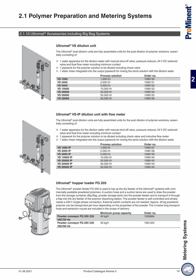
191
2.1.10 Ultromat® Accessories including Big Bag Systems
Ultromat® VS dilution unitThe Ultromat® post dilution units are fully assembled units for the post dilution of polymer solutions, essen-tially consisting of:
■ 1 water apparatus for the dilution water with manual shut-off valve, pressure reducer, 24 V DC solenoid valve and float flow meter including minimum contact
■ 1 pipework for the polymer solution to be diluted including check valve ■ 1 static mixer integrated into the output pipework for mixing the stock solution with the dilution water
Process solution Order no.VS 1000 1,000 l/h 1096130VS 2000 2,000 l/h 1096131VS 5000 5,000 l/h 1096132VS 10000 10,000 l/h 1096133VS 20000 20,000 l/h 1096134VS 30000 30,000 l/h 1096135VS 50000 50,000 l/h 1096136
Ultromat® VS-IP dilution unit with flow meterThe Ultromat® post dilution units are fully assembled units for the post dilution of polymer solutions, essen-tially consisting of:
■ 1 water apparatus for the dilution water with manual shut-off valve, pressure reducer, 24 V DC solenoid valve and float flow meter including minimum contact
■ 1 pipework for the polymer solution to be diluted including check valve and inductive flow meter ■ 1 static mixer integrated into the output pipework for mixing the stock solution with the dilution water
Process solution Order no.VS 1000 IP 1,000 l/h 1096137VS 2000 IP 2,000 l/h 1096138VS 5000 IP 5,000 l/h 1096139VS 10000 IP 10,000 l/h 1096140VS 20000 IP 20,000 l/h 1096142VS 30000 IP 30,000 l/h 1096143VS 50000 IP 50,000 l/h 1096144
Ultromat® hopper loader FG 205The Ultromat® powder feeder FG 205 is used to top up the dry feeder of the Ultromat® systems with com-mercially available powdered polymers. A suction hose and a suction lance are used to draw the powder from the storage container (Big Bag, powder storage tank) into the powder feeder and to transport it through a flap into the dry feeder of the polymer dissolving station. The powder feeder is self-controlled and simply needs a 230 V single-phase connection. External switch contacts are not needed. Approx. 40 kg powdered polymer can be transported per hour depending on the properties of the powder. The 4-metre long transport hose and extraction nozzle are included in the scope of delivery.
Minimum pump capacity Order no.Powder conveyor FG 205 230 VAC/50 Hz
40 kg/h 1000664
Powder conveyor FG 205 230 VAC/60 Hz
40 kg/h 1061422
2.1 Polymer Preparation and Metering Systems
01.06.2021 Product Catalogue Volume 3
Met
erin
g Sy
stem
s

192
Powder pre-storage tankThe powder pre-storage tank is used for interim storage of powdered polymers that are delivered in Big-Bags. The Big-Bag is suspended over the tank on a frame and emptied into the powder pre-storage tank.
Order no.Powder pre-storage tank 1005573
Powder pre-storage tank with bag tipperThe powder pre-storage tank with bag tipper is used for interim storage of powdered polymers delivered in 25 kg sacks.
Order no.Powder pre-storage tank with bag tipper 1025137
2.1 Polymer Preparation and Metering Systems
01.06.2021Product Catalogue Volume 3
Met
erin
g Sy
stem
s
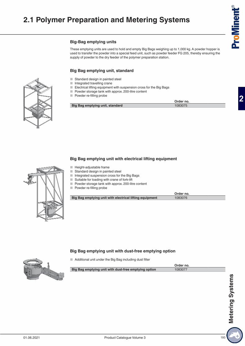
193
Big-Bag emptying unitsThese emptying units are used to hold and empty Big Bags weighing up to 1,000 kg. A powder hopper is used to transfer the powder into a special feed unit, such as powder feeder FG 205, thereby ensuring the supply of powder to the dry feeder of the polymer preparation station.
Big Bag emptying unit, standard
■ Standard design in painted steel ■ Integrated travelling crane ■ Electrical lifting equipment with suspension cross for the Big Bags ■ Powder storage tank with approx. 200-litre content ■ Powder re-filling probe
Order no.Big Bag emptying unit, standard 1083075
Big Bag emptying unit with electrical lifting equipment
■ Height-adjustable frame ■ Standard design in painted steel ■ Integrated suspension cross for the Big Bags ■ Suitable for loading with crane of fork-lift ■ Powder storage tank with approx. 200-litre content ■ Powder re-filling probe
Order no.Big Bag emptying unit with electrical lifting equipment 1083076
Big Bag emptying unit with dust-free emptying option
■ Additional unit under the Big Bag including dust filterOrder no.
Big Bag emptying unit with dust-free emptying option 1083077
2.1 Polymer Preparation and Metering Systems
01.06.2021 Product Catalogue Volume 3
Met
erin
g Sy
stem
s
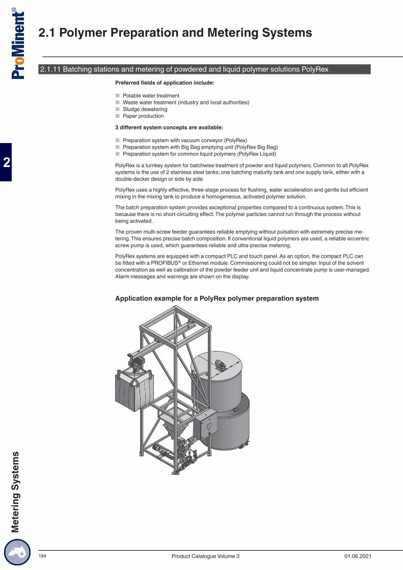
194
2.1.11 Batching stations and metering of powdered and liquid polymer solutions PolyRexPreferred fields of application include:
■ Potable water treatment ■ Waste water treatment (industry and local authorities) ■ Sludge dewatering ■ Paper production
3 different system concepts are available:
■ Preparation system with vacuum conveyor (PolyRex) ■ Preparation system with Big Bag emptying unit (PolyRex Big Bag) ■ Preparation system for common liquid polymers (PolyRex Liquid)
PolyRex is a turnkey system for batchwise treatment of powder and liquid polymers. Common to all PolyRex systems is the use of 2 stainless steel tanks; one batching maturity tank and one supply tank, either with a double-decker design or side by side.
PolyRex uses a highly effective, three-stage process for flushing, water acceleration and gentle but efficient mixing in the mixing tank to produce a homogeneous, activated polymer solution.
The batch preparation system provides exceptional properties compared to a continuous system. This is because there is no short-circuiting effect. The polymer particles cannot run through the process without being activated.
The proven multi-screw feeder guarantees reliable emptying without pulsation with extremely precise me-tering. This ensures precise batch composition. If conventional liquid polymers are used, a reliable eccentric screw pump is used, which guarantees reliable and ultra-precise metering.
PolyRex systems are equipped with a compact PLC and touch panel. As an option, the compact PLC can be fitted with a PROFIBUS® or Ethernet module. Commissioning could not be simpler. Input of the solvent concentration as well as calibration of the powder feeder unit and liquid concentrate pump is user-managed. Alarm messages and warnings are shown on the display.
Application example for a PolyRex polymer preparation system
2.1 Polymer Preparation and Metering Systems
01.06.2021Product Catalogue Volume 3
Met
erin
g Sy
stem
s
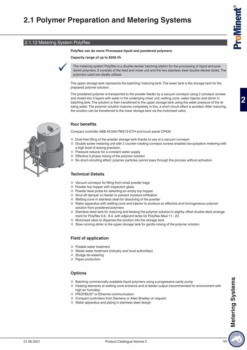
195
2.1.12 Metering System PolyRexPolyRex can do more: Processes liquid and powdered polymers.
Capacity range of up to 8200 l/h
9 The metering system PolyRex is a double-decker batching station for the processing of liquid and pow-dered polymers. It consists of the feed and mixer unit and the two stainless steel double-decker tanks. The polymers used are ideally utilised.
The upper storage tank represents the batching/ maturing tank. The lower tank is the storage tank for the prepared polymer solution.
The powdered polymer is transported to the powder feeder by a vacuum conveyor using 2 conveyor screws and mixed into 3 layers with water in the underlying mixer unit; wetting cone, water injector and stirrer in batching tank. The solution is then transferred to the upper storage tank using the water pressure of the di-luting water. The polymer solution matures completely in this, a short circuit effect is avoided. After maturing, the solution can be transferred to the lower storage tank via the motorised valve.
Your benefitsCompact controller ABB AC500 PM573-ETH and touch panel CP635
■ Dust-free filling of the powder storage tank thanks to use of a vacuum conveyor ■ Double screw metering unit with 2 counter-rotating conveyor screws enables low-pulsation metering with
a high level of dosing precision. ■ Pressure reducer for a constant water supply ■ Effective 3-phase mixing of the polymer solution ■ No short-circuiting effect: polymer particles cannot pass through the process without activation
Technical Details
■ Vacuum conveyor for filling from small powder bags ■ Powder top hopper with inspection glass ■ Powder level probe for detecting an empty top hopper ■ Shut-off damper on feeder to prevent moisture infiltration ■ Wetting cone in stainless steel for dissolving of the powder ■ Water apparatus with wetting cone and injector to produce an effective and homogeneous polymer
solution from powdered polymers ■ Stainless steel tank for maturing and feeding the polymer solution in slightly offset double-deck arrange-
ment for PolyRex 0.6 - 8.4, with adjacent tanks for PolyRex Maxi 11 - 23 ■ Motorised valve to dispense the solution into the storage tank ■ Slow-running stirrer in the upper storage tank for gentle mixing of the polymer solution
Field of application
■ Potable water treatment ■ Waste water treatment (industry and local authorities) ■ Sludge de-watering ■ Paper production
Options
■ Batching commercially-available liquid polymers using a progressive cavity pump ■ Heating elements at wetting cone entrance and at feeder output (recommended for environment with
high air humidity) ■ PROFIBUS® or Ethernet communication ■ Compact controllers from Siemens or Allen Bradley on request ■ Water apparatus and piping in stainless steel design
2.1 Polymer Preparation and Metering Systems
01.06.2021 Product Catalogue Volume 3
Met
erin
g Sy
stem
s
196
Accessories
■ Re-dilution with highly effective static mixer ■ Progressive cavity pump with speed control ■ Electromagnetic flow meter for precise control of the metering pump
2.1 Polymer Preparation and Metering Systems
01.06.2021Product Catalogue Volume 3
Met
erin
g Sy
stem
s

197
Technical DataProduct designation Tank contents Discharge volume Polymer dosing
capacity m3 l/h kg/hPolyRex 0.6 2 x 0.3 240 1.2PolyRex 1.0 2 x 0.6 460 2.3PolyRex 2.0 2 x 1.0 940 4.7PolyRex 3.0 2 x 1.5 1,280 6.4PolyRex 4.0 2 x 2.0 1,900 9.5PolyRex 5.4 2 x 2.7 2,400 12.0PolyRex 6.6 2 x 3.3 3,200 16.0PolyRex 8.4 2 x 4.2 3,820 19.2PolyRex Maxi 11 2 x 5.5 5,100 25.5PolyRex Maxi 16 2 x 8.0 6,600 33.0PolyRex Maxi 23 2 x 11.5 8,200 41.0
2.1 Polymer Preparation and Metering Systems
01.06.2021 Product Catalogue Volume 3
Met
erin
g Sy
stem
s
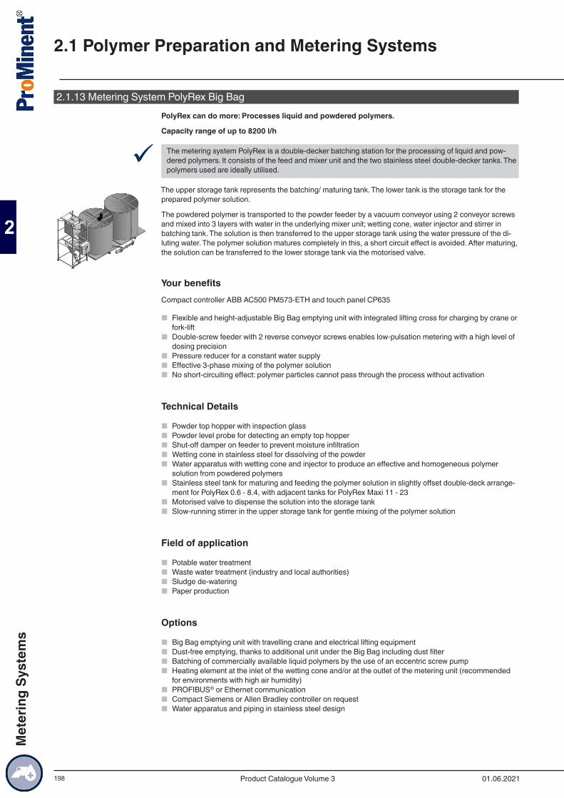
198
2.1.13 Metering System PolyRex Big BagPolyRex can do more: Processes liquid and powdered polymers.
Capacity range of up to 8200 l/h
9 The metering system PolyRex is a double-decker batching station for the processing of liquid and pow-dered polymers. It consists of the feed and mixer unit and the two stainless steel double-decker tanks. The polymers used are ideally utilised.
The upper storage tank represents the batching/ maturing tank. The lower tank is the storage tank for the prepared polymer solution.
The powdered polymer is transported to the powder feeder by a vacuum conveyor using 2 conveyor screws and mixed into 3 layers with water in the underlying mixer unit; wetting cone, water injector and stirrer in batching tank. The solution is then transferred to the upper storage tank using the water pressure of the di-luting water. The polymer solution matures completely in this, a short circuit effect is avoided. After maturing, the solution can be transferred to the lower storage tank via the motorised valve.
Your benefitsCompact controller ABB AC500 PM573-ETH and touch panel CP635
■ Flexible and height-adjustable Big Bag emptying unit with integrated lifting cross for charging by crane or fork-lift
■ Double-screw feeder with 2 reverse conveyor screws enables low-pulsation metering with a high level of dosing precision
■ Pressure reducer for a constant water supply ■ Effective 3-phase mixing of the polymer solution ■ No short-circuiting effect: polymer particles cannot pass through the process without activation
Technical Details
■ Powder top hopper with inspection glass ■ Powder level probe for detecting an empty top hopper ■ Shut-off damper on feeder to prevent moisture infiltration ■ Wetting cone in stainless steel for dissolving of the powder ■ Water apparatus with wetting cone and injector to produce an effective and homogeneous polymer
solution from powdered polymers ■ Stainless steel tank for maturing and feeding the polymer solution in slightly offset double-deck arrange-
ment for PolyRex 0.6 - 8.4, with adjacent tanks for PolyRex Maxi 11 - 23 ■ Motorised valve to dispense the solution into the storage tank ■ Slow-running stirrer in the upper storage tank for gentle mixing of the polymer solution
Field of application
■ Potable water treatment ■ Waste water treatment (industry and local authorities) ■ Sludge de-watering ■ Paper production
Options
■ Big Bag emptying unit with travelling crane and electrical lifting equipment ■ Dust-free emptying, thanks to additional unit under the Big Bag including dust filter ■ Batching of commercially available liquid polymers by the use of an eccentric screw pump ■ Heating element at the inlet of the wetting cone and/or at the outlet of the metering unit (recommended
for environments with high air humidity) ■ PROFIBUS® or Ethernet communication ■ Compact Siemens or Allen Bradley controller on request ■ Water apparatus and piping in stainless steel design
2.1 Polymer Preparation and Metering Systems
01.06.2021Product Catalogue Volume 3
Met
erin
g Sy
stem
s
199
Accessories
■ Re-dilution with highly effective static mixer ■ Eccentric screw pump with speed control ■ Electromagnetic flow meter for the precise control of the metering pump
2.1 Polymer Preparation and Metering Systems
01.06.2021 Product Catalogue Volume 3
Met
erin
g Sy
stem
s
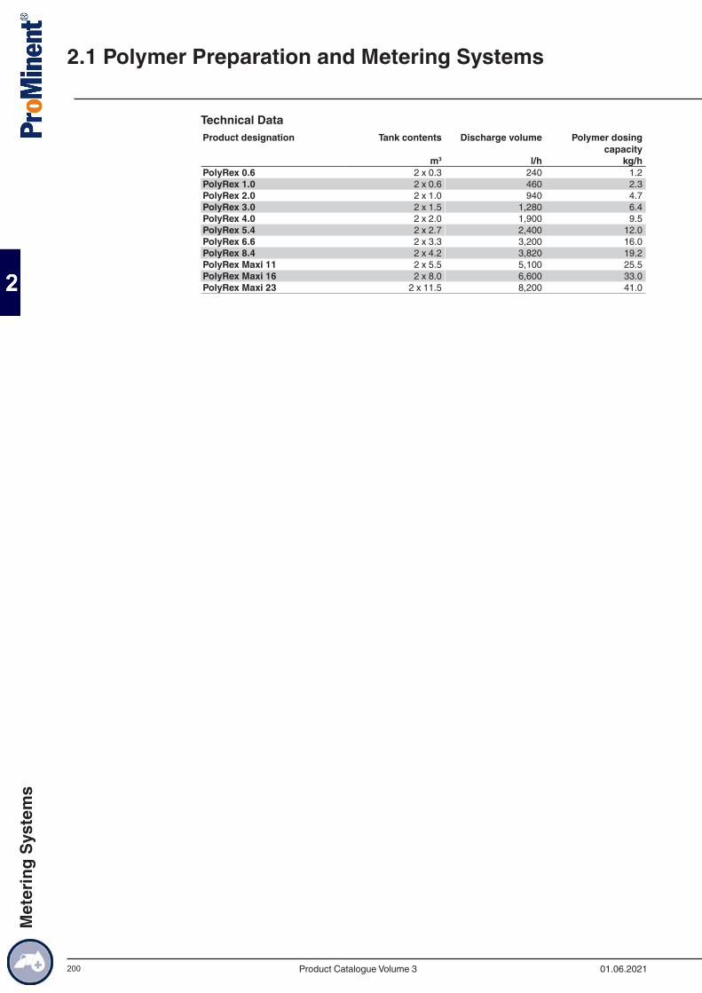
200
Technical DataProduct designation Tank contents Discharge volume Polymer dosing
capacity m3 l/h kg/hPolyRex 0.6 2 x 0.3 240 1.2PolyRex 1.0 2 x 0.6 460 2.3PolyRex 2.0 2 x 1.0 940 4.7PolyRex 3.0 2 x 1.5 1,280 6.4PolyRex 4.0 2 x 2.0 1,900 9.5PolyRex 5.4 2 x 2.7 2,400 12.0PolyRex 6.6 2 x 3.3 3,200 16.0PolyRex 8.4 2 x 4.2 3,820 19.2PolyRex Maxi 11 2 x 5.5 5,100 25.5PolyRex Maxi 16 2 x 8.0 6,600 33.0PolyRex Maxi 23 2 x 11.5 8,200 41.0
2.1 Polymer Preparation and Metering Systems
01.06.2021Product Catalogue Volume 3
Met
erin
g Sy
stem
s
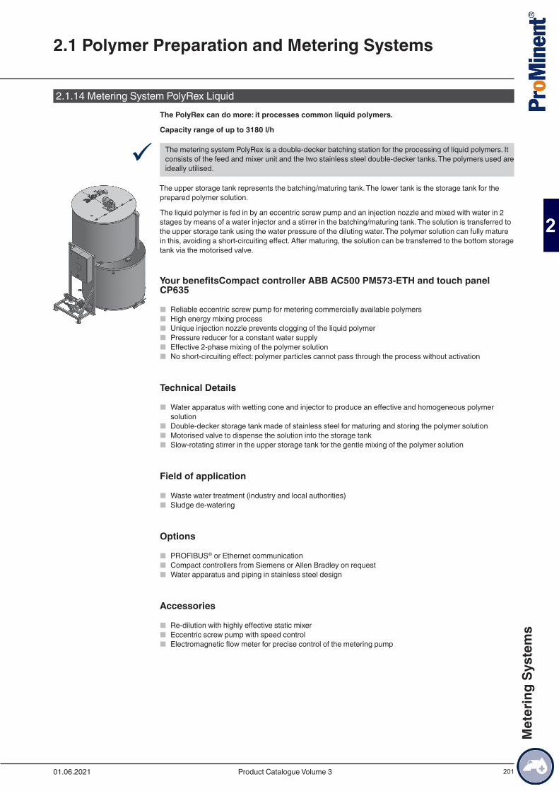
201
2.1.14 Metering System PolyRex LiquidThe PolyRex can do more: it processes common liquid polymers.
Capacity range of up to 3180 l/h
9 The metering system PolyRex is a double-decker batching station for the processing of liquid polymers. It consists of the feed and mixer unit and the two stainless steel double-decker tanks. The polymers used are ideally utilised.
The upper storage tank represents the batching/maturing tank. The lower tank is the storage tank for the prepared polymer solution.
The liquid polymer is fed in by an eccentric screw pump and an injection nozzle and mixed with water in 2 stages by means of a water injector and a stirrer in the batching/maturing tank. The solution is transferred to the upper storage tank using the water pressure of the diluting water. The polymer solution can fully mature in this, avoiding a short-circuiting effect. After maturing, the solution can be transferred to the bottom storage tank via the motorised valve.
Your benefitsCompact controller ABB AC500 PM573-ETH and touch panel CP635
■ Reliable eccentric screw pump for metering commercially available polymers ■ High energy mixing process ■ Unique injection nozzle prevents clogging of the liquid polymer ■ Pressure reducer for a constant water supply ■ Effective 2-phase mixing of the polymer solution ■ No short-circuiting effect: polymer particles cannot pass through the process without activation
Technical Details
■ Water apparatus with wetting cone and injector to produce an effective and homogeneous polymer solution
■ Double-decker storage tank made of stainless steel for maturing and storing the polymer solution ■ Motorised valve to dispense the solution into the storage tank ■ Slow-rotating stirrer in the upper storage tank for the gentle mixing of the polymer solution
Field of application
■ Waste water treatment (industry and local authorities) ■ Sludge de-watering
Options
■ PROFIBUS® or Ethernet communication ■ Compact controllers from Siemens or Allen Bradley on request ■ Water apparatus and piping in stainless steel design
Accessories
■ Re-dilution with highly effective static mixer ■ Eccentric screw pump with speed control ■ Electromagnetic flow meter for precise control of the metering pump
2.1 Polymer Preparation and Metering Systems
01.06.2021 Product Catalogue Volume 3
Met
erin
g Sy
stem
s

202
Technical DataProduct designation Tank contents m3 Discharge volume
l/hPolymer dosing
capacity kg/h m3 l/h kg/hPolyRex Liquid 1.0 0.5 1,060 5.3PolyRex Liquid 2.0 1.0 1,900 9.5PolyRex Liquid 3.0 1.5 2,480 12.4PolyRex Liquid 4.0 2.0 3,180 15.9
Note:The metering rate of liquid polymer in kg/h denotes a 100 % active ingredient content. Naturally, the concentration of the active ingredient in the systems can be adjusted to the commercially available liquid polymers with a 30 - 60 % active ingredient percentage.
2.1 Polymer Preparation and Metering Systems
01.06.2021Product Catalogue Volume 3
Met
erin
g Sy
stem
s
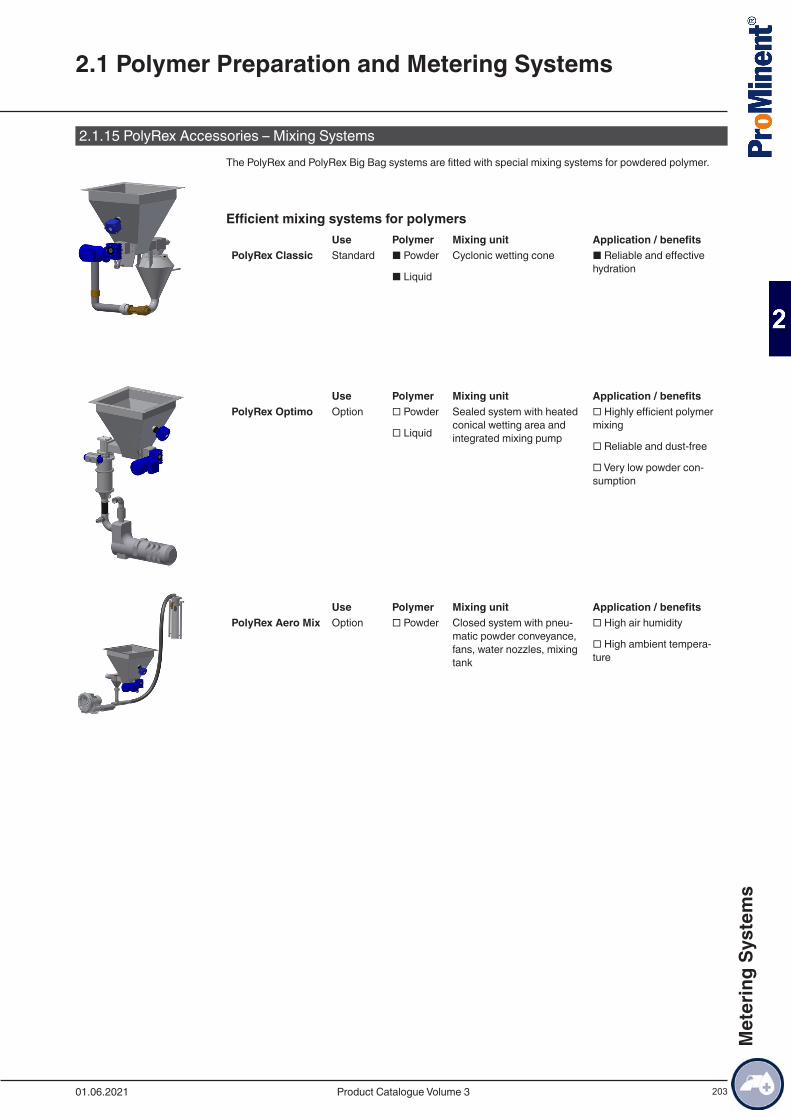
203
2.1.15 PolyRex Accessories – Mixing SystemsThe PolyRex and PolyRex Big Bag systems are fitted with special mixing systems for powdered polymer.
Efficient mixing systems for polymers Use Polymer Mixing unit Application / benefitsPolyRex Classic Standard ■ Powder
■ Liquid
Cyclonic wetting cone ■ Reliable and effective hydration
Use Polymer Mixing unit Application / benefitsPolyRex Optimo Option □ Powder
□ Liquid
Sealed system with heated conical wetting area and integrated mixing pump
□ Highly efficient polymer mixing
□ Reliable and dust-free
□ Very low powder con-sumption
Use Polymer Mixing unit Application / benefitsPolyRex Aero Mix Option □ Powder
Closed system with pneu-matic powder conveyance, fans, water nozzles, mixing tank
□ High air humidity
□ High ambient tempera-ture
2.1 Polymer Preparation and Metering Systems
01.06.2021 Product Catalogue Volume 3
Met
erin
g Sy
stem
s
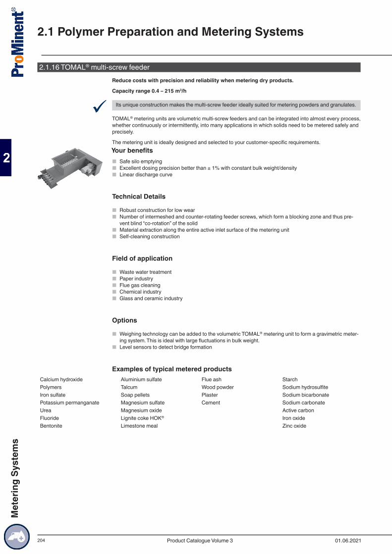
204
2.1.16 TOMAL® multi-screw feederReduce costs with precision and reliability when metering dry products.
Capacity range 0.4 – 215 m3/h
9 Its unique construction makes the multi-screw feeder ideally suited for metering powders and granulates.
TOMAL® metering units are volumetric multi-screw feeders and can be integrated into almost every process, whether continuously or intermittently, into many applications in which solids need to be metered safely and precisely.
The metering unit is ideally designed and selected to your customer-specific requirements.Your benefits
■ Safe silo emptying ■ Excellent dosing precision better than ± 1% with constant bulk weight/density ■ Linear discharge curve
Technical Details
■ Robust construction for low wear ■ Number of intermeshed and counter-rotating feeder screws, which form a blocking zone and thus pre-
vent blind “co-rotation” of the solid ■ Material extraction along the entire active inlet surface of the metering unit ■ Self-cleaning construction
Field of application
■ Waste water treatment ■ Paper industry ■ Flue gas cleaning ■ Chemical industry ■ Glass and ceramic industry
Options
■ Weighing technology can be added to the volumetric TOMAL® metering unit to form a gravimetric meter-ing system. This is ideal with large fluctuations in bulk weight.
■ Level sensors to detect bridge formation
Examples of typical metered productsCalcium hydroxide Aluminium sulfate Flue ash StarchPolymers Talcum Wood powder Sodium hydrosulfiteIron sulfate Soap pellets Plaster Sodium bicarbonatePotassium permanganate Magnesium sulfate Cement Sodium carbonateUrea Magnesium oxide Active carbonFluoride Lignite coke HOK® Iron oxideBentonite Limestone meal Zinc oxide
2.1 Polymer Preparation and Metering Systems
01.06.2021Product Catalogue Volume 3
Met
erin
g Sy
stem
s
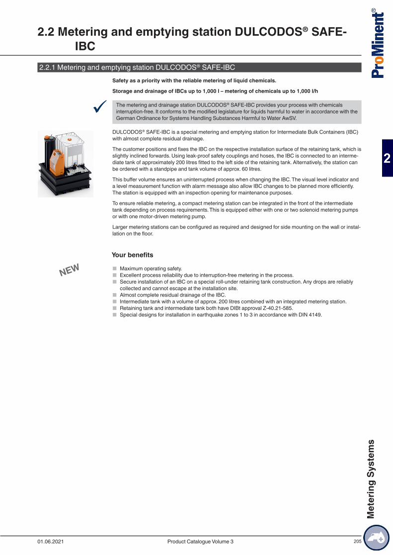
205
2.2.1 Metering and emptying station DULCODOS® SAFE-IBCSafety as a priority with the reliable metering of liquid chemicals.
Storage and drainage of IBCs up to 1,000 l – metering of chemicals up to 1,000 l/h
9 The metering and drainage station DULCODOS® SAFE-IBC provides your process with chemicals interruption-free. It conforms to the modified legislature for liquids harmful to water in accordance with the German Ordinance for Systems Handling Substances Harmful to Water AwSV.
DULCODOS® SAFE-IBC is a special metering and emptying station for Intermediate Bulk Containers (IBC) with almost complete residual drainage.
The customer positions and fixes the IBC on the respective installation surface of the retaining tank, which is slightly inclined forwards. Using leak-proof safety couplings and hoses, the IBC is connected to an interme-diate tank of approximately 200 litres fitted to the left side of the retaining tank. Alternatively, the station can be ordered with a standpipe and tank volume of approx. 60 litres.
This buffer volume ensures an uninterrupted process when changing the IBC. The visual level indicator and a level measurement function with alarm message also allow IBC changes to be planned more efficiently. The station is equipped with an inspection opening for maintenance purposes.
To ensure reliable metering, a compact metering station can be integrated in the front of the intermediate tank depending on process requirements. This is equipped either with one or two solenoid metering pumps or with one motor-driven metering pump.
Larger metering stations can be configured as required and designed for side mounting on the wall or instal-lation on the floor.
Your benefits
■ Maximum operating safety. ■ Excellent process reliability due to interruption-free metering in the process. ■ Secure installation of an IBC on a special roll-under retaining tank construction. Any drops are reliably
collected and cannot escape at the installation site. ■ Almost complete residual drainage of the IBC. ■ Intermediate tank with a volume of approx. 200 litres combined with an integrated metering station. ■ Retaining tank and intermediate tank both have DIBt approval Z-40.21-585. ■ Special designs for installation in earthquake zones 1 to 3 in accordance with DIN 4149.
2.2 Metering and emptying station DULCODOS® SAFE-IBC
01.06.2021 Product Catalogue Volume 3
Met
erin
g Sy
stem
s
206
Technical Details
■ Robust welded construction of the PE-HD retaining tank with a total volume of 1,300 litres ■ Internal steel-reinforced PE-HD bracing on all sides ■ PE-HD intermediate tank holding approx. 200 l, alternatively PE-HD standpipe holding approx. 60 l can
be selected ■ For installation indoors at temperatures of up to 35 °C ■ Outer dimensions approx. 1,840 x 1,850 x 2,098 mm (W x D x H) ■ Retaining tank and intermediate tank with German Institute for Building Technology (DIBt) certification ■ For chemicals with a density of up to max. 1.8 kg/dm3
■ For liquids on the Media lists 40-1.1 published by the DIBt ■ Installation surface for the IBC tilted forwards measuring approximately 1,010 x 1,620 (W x D) with grille
(polyester resin/GRP) on a special load-bearing construction to withstand a maximum load of 2,000 kg, stop rail to the rear of the station and fixing block at the front
■ Roll-under pallet base of retaining tank with a height of approx. 100 mm ■ Special designs for installation in earthquake zones 1 to 3 in accordance with DIN 4149, see design
versions ■ Connection of the IBC to the intermediate tank or standpipe:
■ dual-acting PP/ FKM quick-release couplings, PP/EPDM options available ■ Secure storage of the connection once uncoupled from the IBC in a recessed collection tray at the
front ■ PVC spiral hose with wire coil, optionally also available in a PTFE material version
■ The intermediate tank or the standpipe act as a compensation vessel for the volume of the IBC, with the principle of communicating pipes technically ruling out the possibility of overfilling
■ Equipment of the intermediate tank or standpipe:
■ drain connector with shut-off valve for the IBC’s hose connector ■ suction-side connector to the metering station with shut-off valve ■ connection for return of the safety overflow line ■ visual level indicator ■ continuous level measurement by liquid level sensors with alarm message ■ screw lid acts as an inspection opening ■ ventilation connectors
■ Metering stations for all solenoid metering pumps and motor-driven metering pumps up to Sigma/ 3 can be integrated: DSUa mini, DSKa Sigma/ 1 - 3
■ Metering stations DSUa, DSWb and customer-specific designs can be set up with side wall mounting and/or floor installation associated and associated connection hoses
■ Fittings and seals in PVC/FKM, PVC/EPDM options available ■ Also available as a mirror-image design ■ A chemical vapour barrier with a vapour recovery line to the IBC can be added to the intermediate tank
for outgassing media ■ A liquid level measurement with radar sensor or ultrasound sensor can be used as an option
Field of application
■ Metering of liquids in chemical and industrial production ■ Drinking water treatment ■ Cooling water treatment ■ Food & beverage ■ Electroplating ■ Paper industry
2.2 Metering and emptying station DULCODOS® SAFE-IBC
01.06.2021Product Catalogue Volume 3
Met
erin
g Sy
stem
s
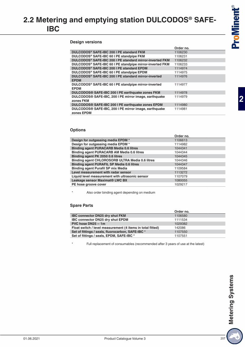
207
Design versionsOrder no.
DULCODOS® SAFE-IBC 200 l PE standard FKM 1106230DULCODOS® SAFE-IBC 60 l PE standpipe FKM 1106231DULCODOS® SAFE-IBC 200 l PE standard mirror-inverted FKM 1106232DULCODOS® SAFE-IBC 60 l PE standpipe mirror-inverted FKM 1106233DULCODOS® SAFE-IBC 200 l PE standard EPDM 1114974DULCODOS® SAFE-IBC 60 l PE standpipe EPDM 1114975DULCODOS® SAFE-IBC 200 l PE standard mirror-inverted EPDM
1114976
DULCODOS® SAFE-IBC 60 l PE standpipe mirror-inverted EPDM
1114977
DULCODOS® SAFE-IBC 200 l PE earthquake zones FKM 1114978DULCODOS® SAFE-IBC, 200 l PE mirror image, earthquake zones FKM
1114979
DULCODOS® SAFE-IBC 200 l PE earthquake zones EPDM 1114980DULCODOS® SAFE-IBC, 200 l PE mirror image, earthquake zones EPDM
1114981
OptionsOrder no.
Design for outgassing media EPDM * 1106613Design for outgassing media EPDM * 1114982Binding agent PURACARB Media 0.6 litres 1044341Binding agent PURACARB AM Media 0.6 litres 1044344Binding agent PK 2050 0.6 litres 1044345Binding agent CHLOROSORB ULTRA Media 0.6 litres 1044346Binding agent PURAFIL SP Media 0.6 litres 1044347Binding agent Purafil SP mix Media 1109584Level measurement with radar sensor 1113272Liquid level measurement with ultrasonic sensor 1107079Leakage sensor Maximat® LWC BX 1080055PE hose groove cover 1029217
* Also order binding agent depending on medium
Spare PartsOrder no.
IBC connector DN25 dry shut FKM 1106580IBC connector DN25 dry shut EPDM 1111534PVC hose DN25 -- 1m 1029382Float switch / level measurement (4 items in total fitted) 142086Set of fittings / seals, fluorocarbon, SAFE-IBC * 1107550Set of fittings / seals, EPDM, SAFE-IBC * 1107551
* Full replacement of consumables (recommended after 3 years of use at the latest)
2.2 Metering and emptying station DULCODOS® SAFE-IBC
01.06.2021 Product Catalogue Volume 3
Met
erin
g Sy
stem
s
208
2.3.1 PE/PP storage tank, generalSafe and reliable handling of chemicals.
Useful capacity 500 l – 50,000 l, indoor and outdoor installation
9 Our plastic storage tanks guarantee compliance with statutory specifications taking into account coun-try-specific approvals, which regulate the production and operation of systems for storage and metering or environmentally-hazardous substances.
Production of plastic storage tanks to customers’ specific requirements and in accordance with the test cer-tification. Constructional design and production are in compliance with the construction and test guidelines as laid down by the German Institute for Building Technology (DIBT).
After specification of the key requirements, including fill medium, installation place, storage and ambient conditions, as well as service life, a statistical calculation of the storage tank volume is produced which then provides the technical basis for detailed construction drawings.
PE-HD and PP plate material is primarily used.
Your benefits
■ Excellent process reliability of the products, thanks to 25 years of experience in the engineering and production of plastic storage tanks.
■ Wide diversity of installation components and storage tank accessories ■ Selection of a suitable material after testing its chemical resistance and process-specific requirements. ■ Excellent manufacturing quality by the use of state-of-the-art plastics processing machines
Field of applicationSuitable for the storage of chemicals. Applications include: Potable water and process water treatment, process technology, waste water technology, electroplating, swimming pool technology and exhaust air treatment.
2.3 Storage and process tanks
01.06.2021Product Catalogue Volume 3
Met
erin
g Sy
stem
s
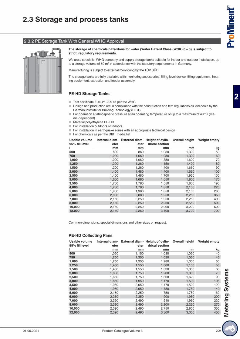
209
2.3.2 PE Storage Tank With General WHG ApprovalThe storage of chemicals hazardous for water (Water Hazard Class (WGK) 0 – 3) is subject to strict, regulatory requirements.
We are a specialist WHG company and supply storage tanks suitable for indoor and outdoor installation, up to a storage volume of 50 m3 in accordance with the statutory requirements in Germany.
Manufacturing is subject to external monitoring by the TÜV SÜD.
The storage tanks are fully available with monitoring accessories, filling level device, filling equipment, heat-ing equipment, extraction and feeder assembly.
PE-HD Storage Tanks
■ Test certificate Z-40.21-229 as per the WHG ■ Design and production are in compliance with the construction and test regulations as laid down by the
German Institute for Building Technology (DIBT) ■ For operation at atmospheric pressure at an operating temperature of up to a maximum of 40 °C (me-
dia-dependent) ■ Material polyethylene PE-HD ■ For installation outdoors or indoors ■ For installation in earthquake zones with an appropriate technical design ■ For chemicals as per the DIBT media list
Usable volume 95% fill level
Internal diam-eter
External diam-eter
Height of cylin-drical section
Overall height Weight empty
l mm mm mm mm kg500 800 860 1,050 1,300 50750 1,000 1,060 1,050 1,300 601,000 1,000 1,060 1,350 1,600 701,250 1,200 1,260 1,150 1,400 801,500 1,200 1,260 1,400 1,650 902,000 1,400 1,480 1,400 1,650 1002,500 1,400 1,480 1,700 1,950 1303,000 1,600 1,680 1,550 1,800 1703,500 1,700 1,780 1,550 1,800 1904,000 1,700 1,780 1,850 2,100 2205,000 1,900 1,980 1,850 2,100 2806,000 2,000 2,080 1,950 2,250 3507,000 2,150 2,250 1,950 2,250 4008,000 2,150 2,250 2,250 2,550 50010,000 2,150 2,250 2,900 3,200 60012,000 2,150 2,250 3,400 3,700 700
Common dimensions, special dimensions and other sizes on request.
PE-HD Collecting PansUsable volume 95% fill level
Internal diam-eter
External diam-eter
Height of cylin-drical section
Overall height Weight empty
l mm mm mm mm kg500 1,050 1,150 1,030 1,050 40750 1,250 1,350 1,030 1,050 451,000 1,250 1,350 1,280 1,300 501,250 1,450 1,550 1,080 1,100 551,500 1,450 1,550 1,330 1,350 602,000 1,650 1,750 1,280 1,300 702,500 1,650 1,750 1,600 1,620 903,000 1,850 1,950 1,470 1,500 1053,500 1,950 2,050 1,470 1,500 1204,000 1,950 2,050 1,750 1,780 1405,000 2,150 2,250 1,750 1,780 1606,000 2,250 2,350 1,900 1,950 2007,000 2,390 2,490 1,910 1,960 2208,000 2,390 2,490 2,200 2,250 27010,000 2,390 2,490 2,750 2,800 35012,000 2,390 2,490 3,300 3,350 450
2.3 Storage and process tanks
01.06.2021 Product Catalogue Volume 3
Met
erin
g Sy
stem
s
210
Common dimensions, special dimensions and other sizes on request.
2.3 Storage and process tanks
01.06.2021Product Catalogue Volume 3
Met
erin
g Sy
stem
s
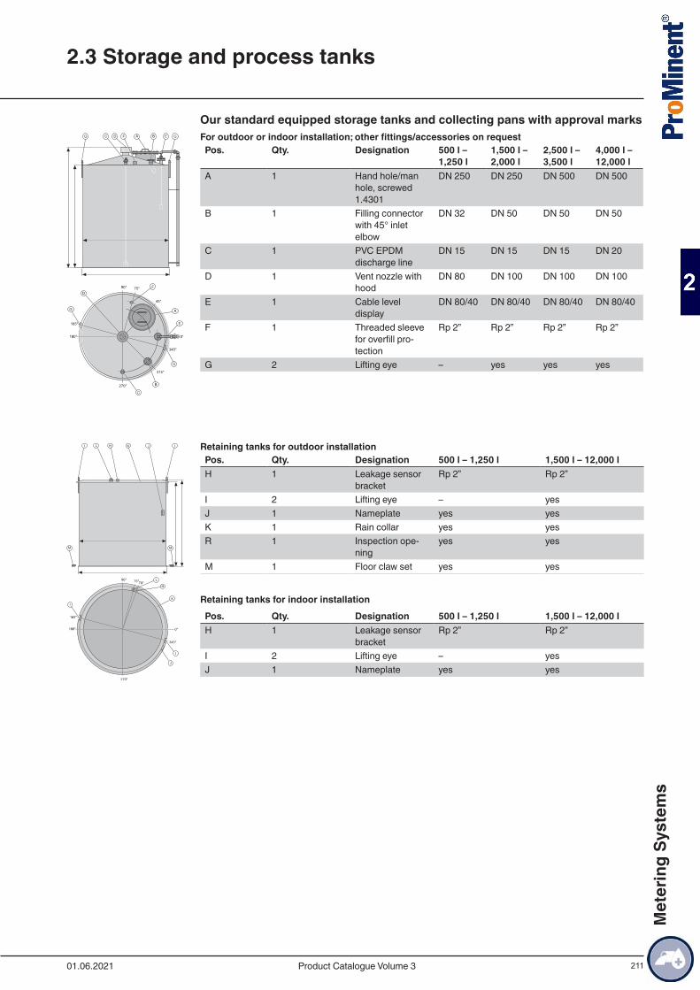
211
Our standard equipped storage tanks and collecting pans with approval marksFor outdoor or indoor installation; other fittings/accessories on requestPos. Qty. Designation 500 l –
1,250 l1,500 l – 2,000 l
2,500 l – 3,500 l
4,000 l – 12,000 l
A 1 Hand hole/man hole, screwed 1.4301
DN 250 DN 250 DN 500 DN 500
B 1 Filling connector with 45° inlet elbow
DN 32 DN 50 DN 50 DN 50
C 1 PVC EPDM discharge line
DN 15 DN 15 DN 15 DN 20
D 1 Vent nozzle with hood
DN 80 DN 100 DN 100 DN 100
E 1 Cable level display
DN 80/40 DN 80/40 DN 80/40 DN 80/40
F 1 Threaded sleeve for overfill pro-tection
Rp 2” Rp 2” Rp 2” Rp 2”
G 2 Lifting eye – yes yes yes
Retaining tanks for outdoor installationPos. Qty. Designation 500 l – 1,250 l 1,500 l – 12,000 lH 1 Leakage sensor
bracketRp 2” Rp 2”
I 2 Lifting eye – yesJ 1 Nameplate yes yesK 1 Rain collar yes yesR 1 Inspection ope-
ningyes yes
M 1 Floor claw set yes yes
Retaining tanks for indoor installationPos. Qty. Designation 500 l – 1,250 l 1,500 l – 12,000 lH 1 Leakage sensor
bracketRp 2” Rp 2”
I 2 Lifting eye – yesJ 1 Nameplate yes yes
2.3 Storage and process tanks
01.06.2021 Product Catalogue Volume 3
Met
erin
g Sy
stem
s
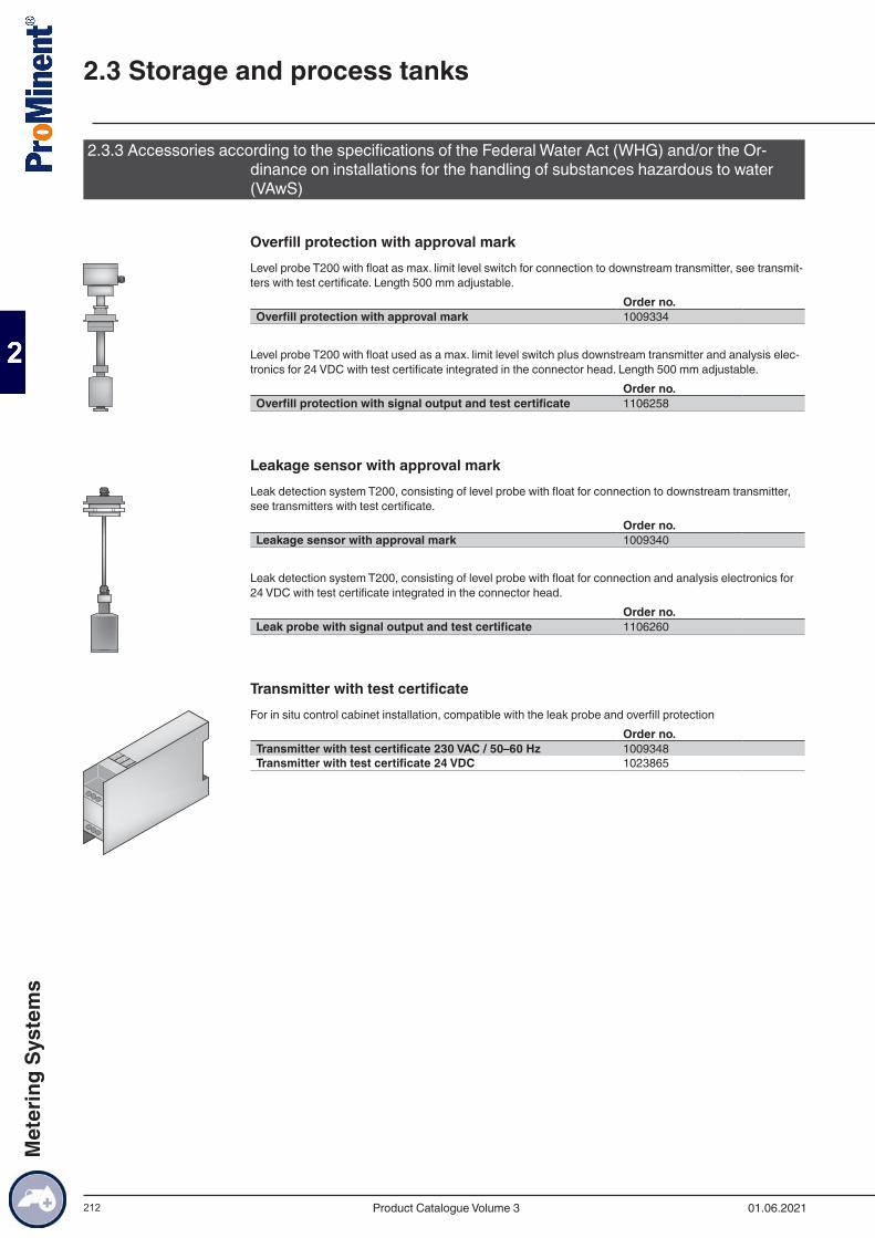
212
2.3.3 Accessories according to the specifications of the Federal Water Act (WHG) and/or the Or-dinance on installations for the handling of substances hazardous to water (VAwS)
Overfill protection with approval markLevel probe T200 with float as max. limit level switch for connection to downstream transmitter, see transmit-ters with test certificate. Length 500 mm adjustable.
Order no.Overfill protection with approval mark 1009334
Level probe T200 with float used as a max. limit level switch plus downstream transmitter and analysis elec-tronics for 24 VDC with test certificate integrated in the connector head. Length 500 mm adjustable.
Order no.Overfill protection with signal output and test certificate 1106258
Leakage sensor with approval markLeak detection system T200, consisting of level probe with float for connection to downstream transmitter, see transmitters with test certificate.
Order no.Leakage sensor with approval mark 1009340
Leak detection system T200, consisting of level probe with float for connection and analysis electronics for 24 VDC with test certificate integrated in the connector head.
Order no.Leak probe with signal output and test certificate 1106260
Transmitter with test certificateFor in situ control cabinet installation, compatible with the leak probe and overfill protection
Order no.Transmitter with test certificate 230 VAC / 50–60 Hz 1009348Transmitter with test certificate 24 VDC 1023865
2.3 Storage and process tanks
01.06.2021Product Catalogue Volume 3
Met
erin
g Sy
stem
s
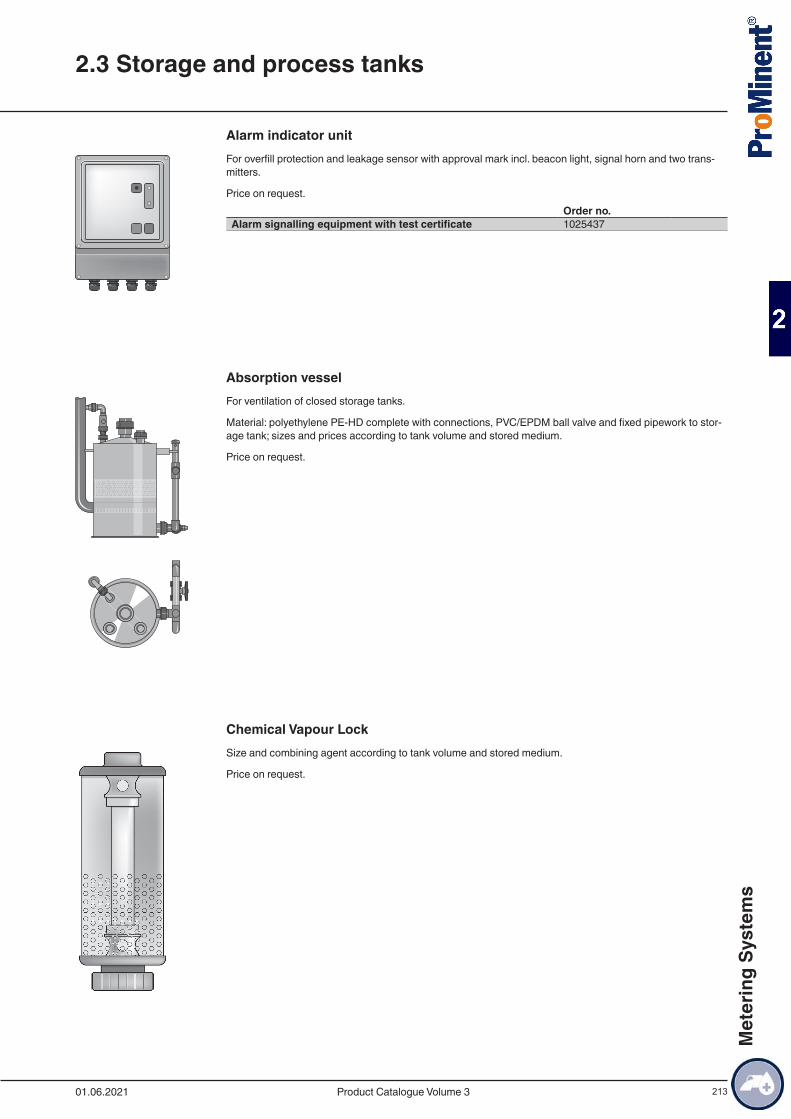
213
Alarm indicator unitFor overfill protection and leakage sensor with approval mark incl. beacon light, signal horn and two trans-mitters.
Price on request.Order no.
Alarm signalling equipment with test certificate 1025437
Absorption vesselFor ventilation of closed storage tanks.
Material: polyethylene PE-HD complete with connections, PVC/EPDM ball valve and fixed pipework to stor-age tank; sizes and prices according to tank volume and stored medium.
Price on request.
Chemical Vapour LockSize and combining agent according to tank volume and stored medium.
Price on request.
2.3 Storage and process tanks
01.06.2021 Product Catalogue Volume 3
Met
erin
g Sy
stem
s
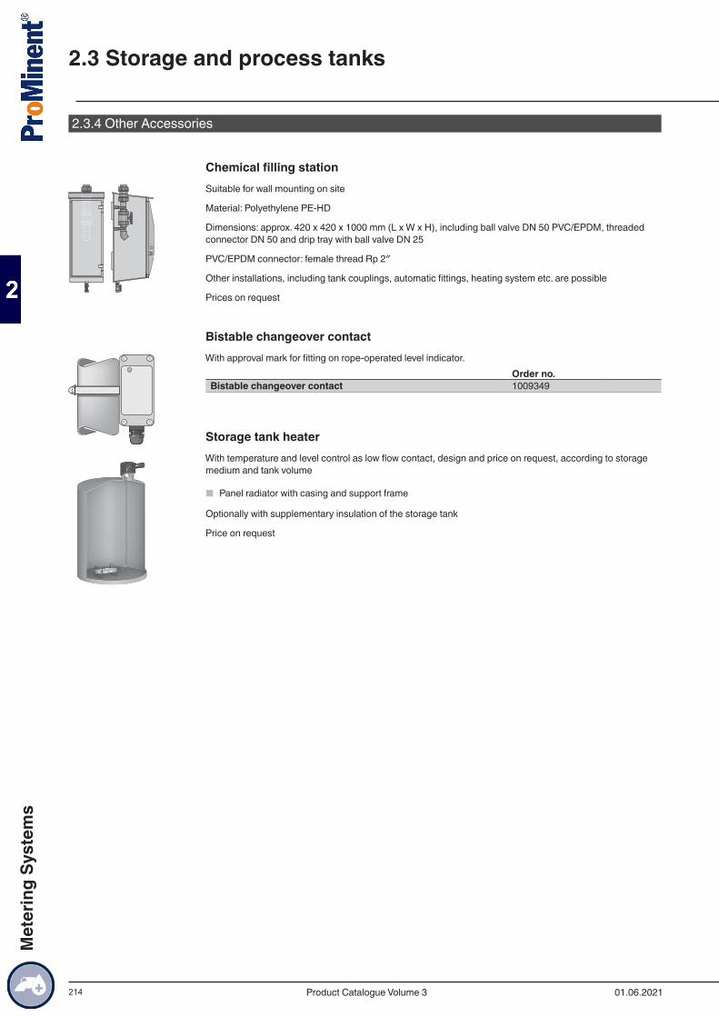
214
2.3.4 Other Accessories
Chemical filling stationSuitable for wall mounting on site
Material: Polyethylene PE-HD
Dimensions: approx. 420 x 420 x 1000 mm (L x W x H), including ball valve DN 50 PVC/EPDM, threaded connector DN 50 and drip tray with ball valve DN 25
PVC/EPDM connector: female thread Rp 2″
Other installations, including tank couplings, automatic fittings, heating system etc. are possible
Prices on request
Bistable changeover contactWith approval mark for fitting on rope-operated level indicator.
Order no.Bistable changeover contact 1009349
Storage tank heaterWith temperature and level control as low flow contact, design and price on request, according to storage medium and tank volume
■ Panel radiator with casing and support frame
Optionally with supplementary insulation of the storage tank
Price on request
2.3 Storage and process tanks
01.06.2021Product Catalogue Volume 3
Met
erin
g Sy
stem
s
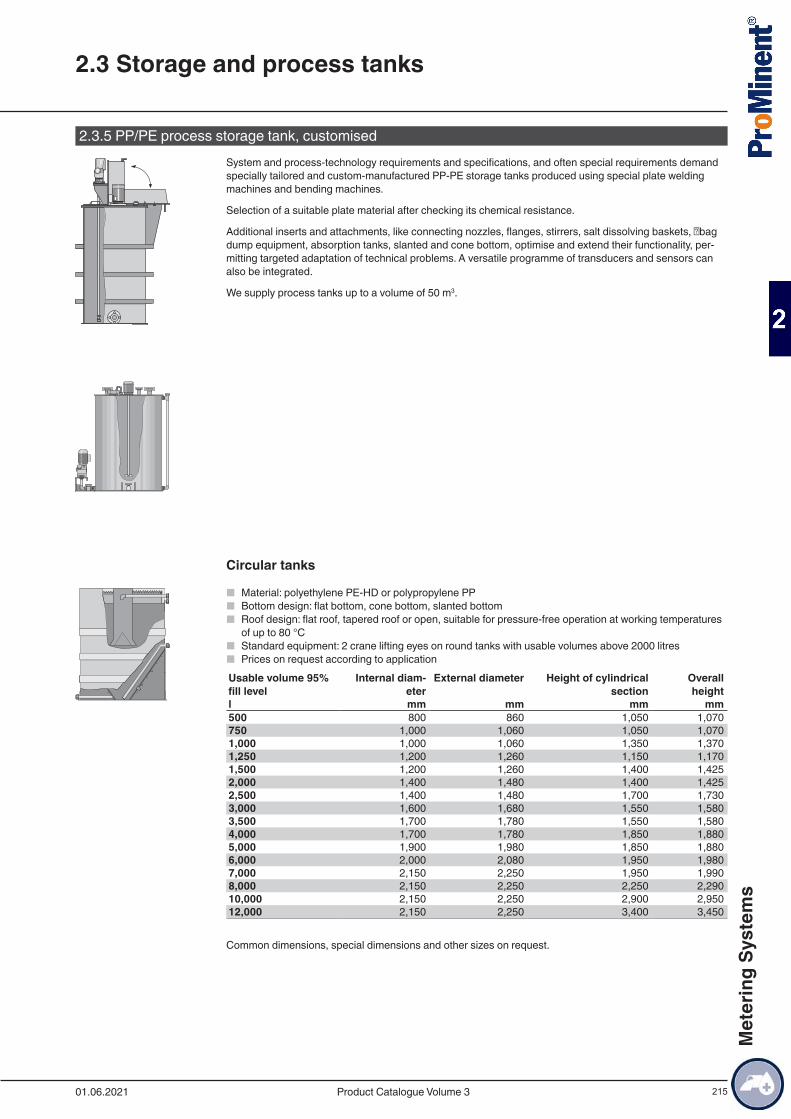
215
2.3.5 PP/PE process storage tank, customisedSystem and process-technology requirements and specifications, and often special requirements demand specially tailored and custom-manufactured PP-PE storage tanks produced using special plate welding machines and bending machines.
Selection of a suitable plate material after checking its chemical resistance.
Additional inserts and attachments, like connecting nozzles, flanges, stirrers, salt dissolving baskets, bag dump equipment, absorption tanks, slanted and cone bottom, optimise and extend their functionality, per-mitting targeted adaptation of technical problems. A versatile programme of transducers and sensors can also be integrated.
We supply process tanks up to a volume of 50 m3.
Circular tanks
■ Material: polyethylene PE-HD or polypropylene PP ■ Bottom design: flat bottom, cone bottom, slanted bottom ■ Roof design: flat roof, tapered roof or open, suitable for pressure-free operation at working temperatures
of up to 80 °C ■ Standard equipment: 2 crane lifting eyes on round tanks with usable volumes above 2000 litres ■ Prices on request according to application
Usable volume 95% fill level
Internal diam-eter
External diameter Height of cylindrical section
Overall height
l mm mm mm mm500 800 860 1,050 1,070750 1,000 1,060 1,050 1,0701,000 1,000 1,060 1,350 1,3701,250 1,200 1,260 1,150 1,1701,500 1,200 1,260 1,400 1,4252,000 1,400 1,480 1,400 1,4252,500 1,400 1,480 1,700 1,7303,000 1,600 1,680 1,550 1,5803,500 1,700 1,780 1,550 1,5804,000 1,700 1,780 1,850 1,8805,000 1,900 1,980 1,850 1,8806,000 2,000 2,080 1,950 1,9807,000 2,150 2,250 1,950 1,9908,000 2,150 2,250 2,250 2,29010,000 2,150 2,250 2,900 2,95012,000 2,150 2,250 3,400 3,450
Common dimensions, special dimensions and other sizes on request.
2.3 Storage and process tanks
01.06.2021 Product Catalogue Volume 3
Met
erin
g Sy
stem
s
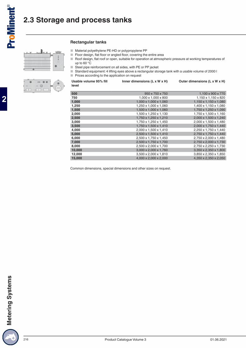
216
Rectangular tanks
■ Material polyethylene PE-HD or polypropylene PP ■ Floor design, flat floor or angled floor, covering the entire area ■ Roof design, flat roof or open, suitable for operation at atmospheric pressure at working temperatures of
up to 60 °C ■ Steel pipe reinforcement on all sides, with PE or PP jacket ■ Standard equipment: 4 lifting eyes above a rectangular storage tank with a usable volume of 2000 l ■ Prices according to the application on request
Usable volume 95% fill level
Inner dimensions (L x W x H) Outer dimensions (L x W x H)
500 950 x 750 x 750 1,100 x 900 x 770750 1,000 x 1,000 x 800 1,150 x 1,150 x 8201,000 1,000 x 1,000 x 1,060 1,150 x 1,150 x 1,0801,250 1,250 x 1,000 x 1,060 1,400 x 1,150 x 1,0801,500 1,500 x 1,000 x 1,060 1,750 x 1,250 x 1,0902,000 1,500 x 1,250 x 1,130 1,750 x 1,500 x 1,1602,500 1,750 x 1,250 x 1,210 2,000 x 1,500 x 1,2403,000 1,750 x 1,250 x 1,450 2,000 x 1,500 x 1,4803,500 1,750 x 1,500 x 1,410 2,000 x 1,750 x 1,4404,000 2,000 x 1,500 x 1,410 2,250 x 1,750 x 1,4405,000 2,500 x 1,500 x 1,410 2,750 x 1,750 x 1,4406,000 2,500 x 1,750 x 1,450 2,750 x 2,000 x 1,4807,000 2,500 x 1,750 x 1,700 2,750 x 2,000 x 1,7308,000 2,500 x 2,000 x 1,700 2,750 x 2,250 x 1,73010,000 3,000 x 2,000 x 1,760 3,350 x 2,350 x 1,80012,000 3,500 x 2,000 x 1,810 3,850 x 2,350 x 1,85015,000 4,000 x 2,000 x 2,000 4,350 x 2,350 x 2,050
Common dimensions, special dimensions and other sizes on request.
2.3 Storage and process tanks
01.06.2021Product Catalogue Volume 3
Met
erin
g Sy
stem
s
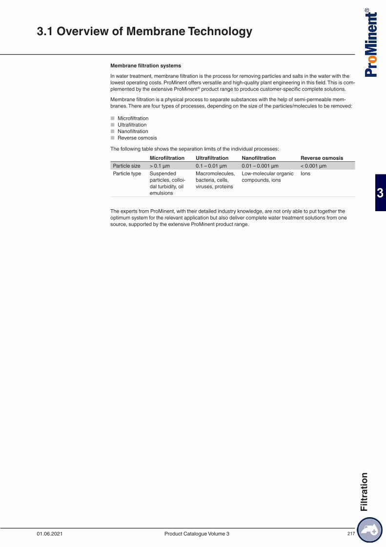
217
Membrane filtration systems
In water treatment, membrane filtration is the process for removing particles and salts in the water with the lowest operating costs. ProMinent offers versatile and high-quality plant engineering in this field. This is com-plemented by the extensive ProMinent® product range to produce customer-specific complete solutions.
Membrane filtration is a physical process to separate substances with the help of semi-permeable mem-branes. There are four types of processes, depending on the size of the particles/molecules to be removed:
■ Microfiltration ■ Ultrafiltration ■ Nanofiltration ■ Reverse osmosis
The following table shows the separation limits of the individual processes: Microfiltration Ultrafiltration Nanofiltration Reverse osmosisParticle size > 0.1 μm 0.1 – 0.01 μm 0.01 – 0.001 μm < 0.001 μmParticle type Suspended
particles, colloi-dal turbidity, oil emulsions
Macromolecules, bacteria, cells, viruses, proteins
Low-molecular organic compounds, ions
Ions
The experts from ProMinent, with their detailed industry knowledge, are not only able to put together the optimum system for the relevant application but also deliver complete water treatment solutions from one source, supported by the extensive ProMinent product range.
3.1 Overview of Membrane Technology
01.06.2021 Product Catalogue Volume 3
Filtr
atio
n

218
3.2.1 Performance Overview of UltrafiltrationUltrafiltration is a membrane process which is increasingly used in water treatment to separate undesired water components. Parasites, bacteria, viruses and high-molecular organic substances as well as other particles are retained.
The applications of ultrafiltration are widespread and may include different types of water.
Typical applications include drinking water, river water, process water, swimming pool water, salt water and waste water.
The tasks range from potable water purification to meet physical and microbiological limit values in accord-ance with the German Drinking Water Ordinance up to the pre-treatment of seawater for desalination by reverse osmosis.
The systems are matched to a specific task by individually selecting the membrane type and the operating mode. ProMinent uses extremely robust and resistant UF membranes and the dead-end principle to ensure optimisation with regard to investment costs, required space and operating costs. With this selection, all raw waters with the exception of waste water can be filtered largely without using chemicals.
The dead-end operation represents the standard operating mode. The raw water flows into the capillaries. The pure water (filtrate) passes through the membrane while the other constituents are retained on the surface of the membrane.
The constituents form a layer on the membrane. The membrane is backwashed fully automatically in regular intervals to remove the filter cake.
Ultrafiltration Systems Basically Consist of:
■ Stainless steel or high-grade coated steel rack ■ Pre-filter to protect the membranes, if required. This filter can be designed as a backflushing filter if
needed. ■ UF membrane modules ■ Pneumatically controlled valves made of high-quality materials ■ Electronic pressure measurement ■ Filtration pump and backflush pump if needed with frequency converter made of suitable high-quality
materials ■ Magnetically inductive flow metering to control the flow rates for filtration and backflushing. ■ Integrated filling system for the backflushing water tank. The backflushing water tank is also integral to
small systems. With larger systems, tanks from our product range can be integrated or an alternative application-specific solution found, depending on the customer’s requirements.
■
PLC with touch screen panel or microprocessor control unit.
The PLC simultaneously monitors all important parameters, such as pressure, pressure difference and flow rates. This ensures that the membranes are ideally protected. The control of pre- and post-treatment processes can be integrated, if required.
Advantages of Ultrafiltration Systems
■ Filtrate values of less than 0.1 NTU independent of the turbidity of the raw water. ■ Molecular weight cut off of the membranes (MWCO) approx. 100 kDa (kilodalton). ■ Best possible retention rates for bacteria (99.9999%) and viruses (99.99% based on MS2 phages). ■ Very easy to use and simple to combine with other systems owing to PLC Programmable Logic Control-
ler with touch screen. ■ Optimum operating processes due to modern measuring and control technology. ■ Complete solutions with perfectly coordinated pre- and post-treatment are available on request.
3.2 Ultrafiltration Systems
01.06.2021Product Catalogue Volume 3
Filtr
atio
n
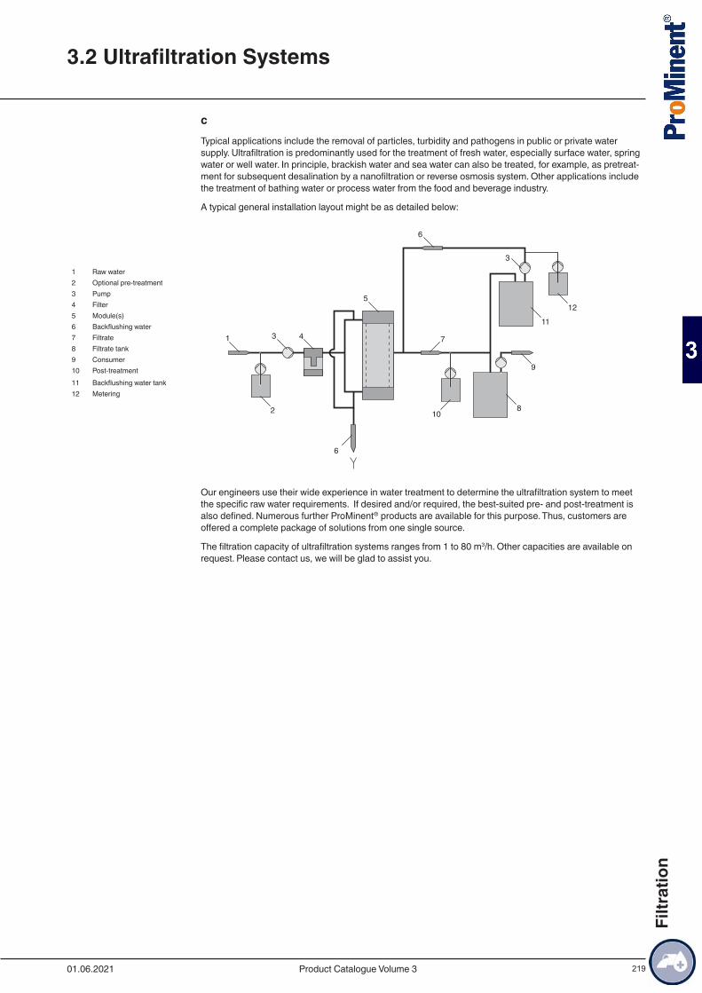
219
cTypical applications include the removal of particles, turbidity and pathogens in public or private water supply. Ultrafiltration is predominantly used for the treatment of fresh water, especially surface water, spring water or well water. In principle, brackish water and sea water can also be treated, for example, as pretreat-ment for subsequent desalination by a nanofiltration or reverse osmosis system. Other applications include the treatment of bathing water or process water from the food and beverage industry.
A typical general installation layout might be as detailed below:
1 Raw water2 Optional pre-treatment3 Pump4 Filter5 Module(s)6 Backflushing water7 Filtrate8 Filtrate tank9 Consumer10 Post-treatment11 Backflushing water tank12 Metering
Our engineers use their wide experience in water treatment to determine the ultrafiltration system to meet the specific raw water requirements. If desired and/or required, the best-suited pre- and post-treatment is also defined. Numerous further ProMinent® products are available for this purpose. Thus, customers are offered a complete package of solutions from one single source.
The filtration capacity of ultrafiltration systems ranges from 1 to 80 m3/h. Other capacities are available on request. Please contact us, we will be glad to assist you.
3.2 Ultrafiltration Systems
01.06.2021 Product Catalogue Volume 3
Filtr
atio
n
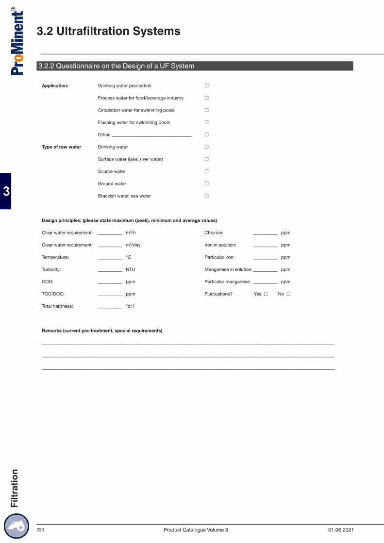
220
3.2.2 Questionnaire on the Design of a UF System
3.2 Ultrafiltration Systems
01.06.2021Product Catalogue Volume 3
Filtr
atio
n
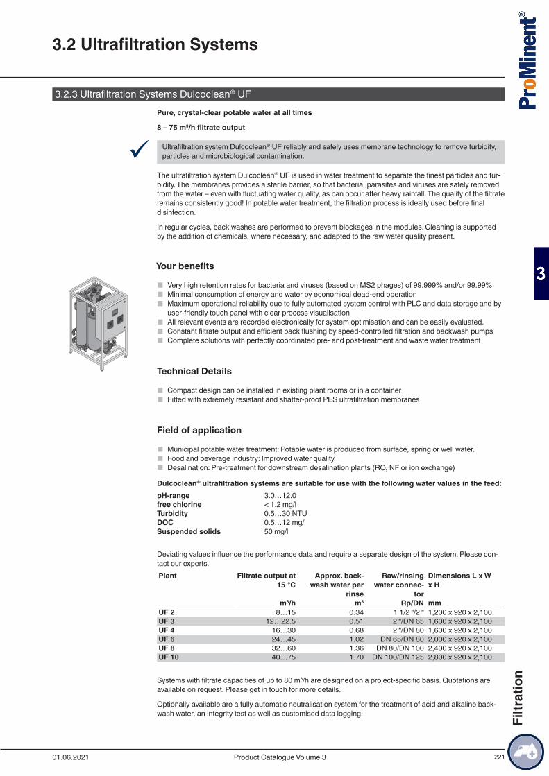
221
3.2.3 Ultrafiltration Systems Dulcoclean® UFPure, crystal-clear potable water at all times
8 – 75 m3/h filtrate output
9 Ultrafiltration system Dulcoclean® UF reliably and safely uses membrane technology to remove turbidity, particles and microbiological contamination.
The ultrafiltration system Dulcoclean® UF is used in water treatment to separate the finest particles and tur-bidity. The membranes provides a sterile barrier, so that bacteria, parasites and viruses are safely removed from the water – even with fluctuating water quality, as can occur after heavy rainfall. The quality of the filtrate remains consistently good! In potable water treatment, the filtration process is ideally used before final disinfection.
In regular cycles, back washes are performed to prevent blockages in the modules. Cleaning is supported by the addition of chemicals, where necessary, and adapted to the raw water quality present.
Your benefits
■ Very high retention rates for bacteria and viruses (based on MS2 phages) of 99.999% and/or 99.99% ■ Minimal consumption of energy and water by economical dead-end operation ■ Maximum operational reliability due to fully automated system control with PLC and data storage and by
user-friendly touch panel with clear process visualisation ■ All relevant events are recorded electronically for system optimisation and can be easily evaluated. ■ Constant filtrate output and efficient back flushing by speed-controlled filtration and backwash pumps ■ Complete solutions with perfectly coordinated pre- and post-treatment and waste water treatment
Technical Details
■ Compact design can be installed in existing plant rooms or in a container ■ Fitted with extremely resistant and shatter-proof PES ultrafiltration membranes
Field of application
■ Municipal potable water treatment: Potable water is produced from surface, spring or well water. ■ Food and beverage industry: Improved water quality. ■ Desalination: Pre-treatment for downstream desalination plants (RO, NF or ion exchange)
Dulcoclean® ultrafiltration systems are suitable for use with the following water values in the feed:pH-range 3.0…12.0free chlorine < 1.2 mg/lTurbidity 0.5…30 NTUDOC 0.5…12 mg/lSuspended solids 50 mg/l
Deviating values influence the performance data and require a separate design of the system. Please con-tact our experts.Plant Filtrate output at
15 °CApprox. back-
wash water per rinse
Raw/rinsing water connec-
tor
Dimensions L x W x H
m3/h m3 Rp/DN mmUF 2 8…15 0.34 1 1/2 “/2 “ 1,200 x 920 x 2,100UF 3 12…22.5 0.51 2 “/DN 65 1,600 x 920 x 2,100UF 4 16…30 0.68 2 “/DN 80 1,600 x 920 x 2,100UF 6 24…45 1.02 DN 65/DN 80 2,000 x 920 x 2,100UF 8 32…60 1.36 DN 80/DN 100 2,400 x 920 x 2,100UF 10 40…75 1.70 DN 100/DN 125 2,800 x 920 x 2,100
Systems with filtrate capacities of up to 80 m3/h are designed on a project-specific basis. Quotations are available on request. Please get in touch for more details.
Optionally available are a fully automatic neutralisation system for the treatment of acid and alkaline back-wash water, an integrity test as well as customised data logging.
3.2 Ultrafiltration Systems
01.06.2021 Product Catalogue Volume 3
Filtr
atio
n
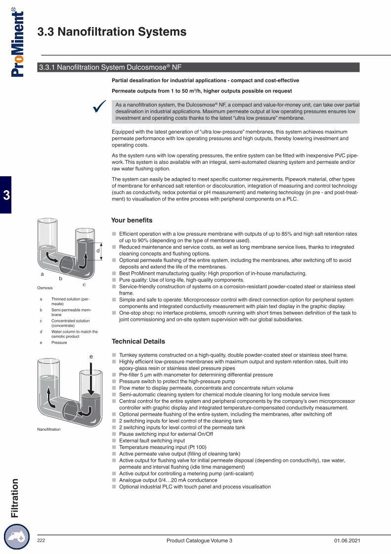
222
3.3.1 Nanofiltration System Dulcosmose® NFPartial desalination for industrial applications - compact and cost-effective
Permeate outputs from 1 to 50 m3/h, higher outputs possible on request
9 As a nanofiltration system, the Dulcosmose® NF, a compact and value-for-money unit, can take over partial desalination in industrial applications. Maximum permeate output at low operating pressures ensures low investment and operating costs thanks to the latest “ultra low pressure” membrane.
Equipped with the latest generation of “ultra low-pressure” membranes, this system achieves maximum permeate performance with low operating pressures and high outputs, thereby lowering investment and operating costs.
As the system runs with low operating pressures, the entire system can be fitted with inexpensive PVC pipe-work. This system is also available with an integral, semi-automated cleaning system and permeate and/or raw water flushing option.
The system can easily be adapted to meet specific customer requirements. Pipework material, other types of membrane for enhanced salt retention or discolouration, integration of measuring and control technology (such as conductivity, redox potential or pH measurement) and metering technology (in pre - and post-treat-ment) to visualisation of the entire process with peripheral components on a PLC.
Your benefits
■ Efficient operation with a low pressure membrane with outputs of up to 85% and high salt retention rates of up to 90% (depending on the type of membrane used).
■ Reduced maintenance and service costs, as well as long membrane service lives, thanks to integrated cleaning concepts and flushing options.
■ Optional permeate flushing of the entire system, including the membranes, after switching off to avoid deposits and extend the life of the membranes.
■ Best ProMinent manufacturing quality: High proportion of in-house manufacturing. ■ Pure quality: Use of long-life, high-quality components. ■ Service-friendly construction of systems on a corrosion-resistant powder-coated steel or stainless steel
frame. ■ Simple and safe to operate: Microprocessor control with direct connection option for peripheral system
components and integrated conductivity measurement with plain text display in the graphic display. ■ One-stop shop: no interface problems, smooth running with short times between definition of the task to
joint commissioning and on-site system supervision with our global subsidiaries.
Technical Details
■ Turnkey systems constructed on a high-quality, double powder-coated steel or stainless steel frame. ■ Highly efficient low-pressure membranes with maximum output and system retention rates, built into
epoxy-glass resin or stainless steel pressure pipes ■ Pre-filter 5 µm with manometer for determining differential pressure ■ Pressure switch to protect the high-pressure pump ■ Flow meter to display permeate, concentrate and concentrate return volume ■ Semi-automatic cleaning system for chemical module cleaning for long module service lives ■ Central control for the entire system and peripheral components by the company’s own microprocessor
controller with graphic display and integrated temperature-compensated conductivity measurement. ■ Optional permeate flushing of the entire system, including the membranes, after switching off ■ 2 switching inputs for level control of the cleaning tank ■ 2 switching inputs for level control of the permeate tank ■ Pause switching input for external On/Off ■ External fault switching input ■ Temperature measuring input (Pt 100) ■ Active permeate valve output (filling of cleaning tank) ■ Active output for flushing valve for initial permeate disposal (depending on conductivity), raw water,
permeate and interval flushing (idle time management) ■ Active output for controlling a metering pump (anti-scalant) ■ Analogue output 0/4…20 mA conductance ■ Optional industrial PLC with touch panel and process visualisation
a Thinned solution (per-
meate)b Semi-permeable mem-
branec Concentrated solution
(concentrate)d Water column to match the
osmotic producte Pressure
Osmosis
Nanofiltration
3.3 Nanofiltration Systems
01.06.2021Product Catalogue Volume 3
Filtr
atio
n

223
Field of application
■ Low-cost alternative to reverse osmosis systems for special desalination tasks, such as the elimination of multiple charged ions or the removal of dyes
■ Partial water softening or water softening in public drinking water ■ Partial desalination in the chemical and pharmaceutical industry, food and beverage industry, metal
processing industry and in electroplating
Nanofiltration is based on the same principle as reverse osmosis. The only difference is that the separation limit is slightly lower. Admittedly this type of membrane filtration retains ions dissolved in water, but to a significantly lesser extent than with reverse osmosis. Ultimately that saves operating costs.
Typical salt retention rates are around 80 – 90%. Multi-value ions (e.g. Ca and Mg) are retained better than single-value ions (e.g. Na, K) so that nanofiltration systems are often also used as an alternative to tradition-al water softening.
In principle with nanofiltration, the raw water to be softened is introduced into a chamber, separated by a semi-permeable diaphragm. An artificial pressure is generated in the chamber against the osmotic pressure gradient. The membrane is permeable to pure water and smaller ions. All other components of the water are retained. This produces partially softened water (permeate) and a concentrated solution (concentrate). ProMinent uses high-quality nano filtration membranes for this process.
3.3 Nanofiltration Systems
01.06.2021 Product Catalogue Volume 3
Filtr
atio
n
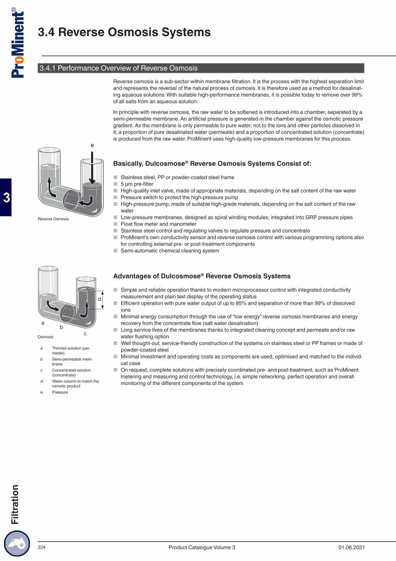
224
3.4.1 Performance Overview of Reverse OsmosisReverse osmosis is a sub-sector within membrane filtration. It is the process with the highest separation limit and represents the reversal of the natural process of osmosis. It is therefore used as a method for desalinat-ing aqueous solutions. With suitable high-performance membranes, it is possible today to remove over 99% of all salts from an aqueous solution.
In principle with reverse osmosis, the raw water to be softened is introduced into a chamber, separated by a semi-permeable membrane. An artificial pressure is generated in the chamber against the osmotic pressure gradient. As the membrane is only permeable to pure water, not to the ions and other particles dissolved in it, a proportion of pure desalinated water (permeate) and a proportion of concentrated solution (concentrate) is produced from the raw water. ProMinent uses high-quality low-pressure membranes for this process.
Basically, Dulcosmose® Reverse Osmosis Systems Consist of:
■ Stainless steel, PP or powder-coated steel frame ■ 5 µm pre-filter ■ High-quality inlet valve, made of appropriate materials, depending on the salt content of the raw water ■ Pressure switch to protect the high-pressure pump ■ High-pressure pump, made of suitable high-grade materials, depending on the salt content of the raw
water ■ Low-pressure membranes, designed as spiral winding modules, integrated into GRP pressure pipes ■ Float flow meter and manometer ■ Stainless steel control and regulating valves to regulate pressure and concentrate ■ ProMinent’s own conductivity sensor and reverse osmosis control with various programming options also
for controlling external pre- or post-treatment components ■ Semi-automatic chemical cleaning system
Advantages of Dulcosmose® Reverse Osmosis Systems
■ Simple and reliable operation thanks to modern microprocessor control with integrated conductivity measurement and plain text display of the operating status
■ Efficient operation with pure water output of up to 85% and separation of more than 99% of dissolved ions
■ Minimal energy consumption through the use of “low energy” reverse osmosis membranes and energy recovery from the concentrate flow (salt water desalination)
■ Long service lives of the membranes thanks to integrated cleaning concept and permeate and/or raw water flushing option
■ Well thought-out, service-friendly construction of the systems on stainless steel or PP frames or made of powder-coated steel
■ Minimal investment and operating costs as components are used, optimised and matched to the individ-ual case
■ On request, complete solutions with precisely coordinated pre- and post-treatment, such as ProMinent metering and measuring and control technology, i.e. simple networking, perfect operation and overall monitoring of the different components of the system
Reverse Osmosis
a Thinned solution (per-
meate)b Semi-permeable mem-
branec Concentrated solution
(concentrate)d Water column to match the
osmotic producte Pressure
Osmosis
3.4 Reverse Osmosis Systems
01.06.2021Product Catalogue Volume 3
Filtr
atio
n
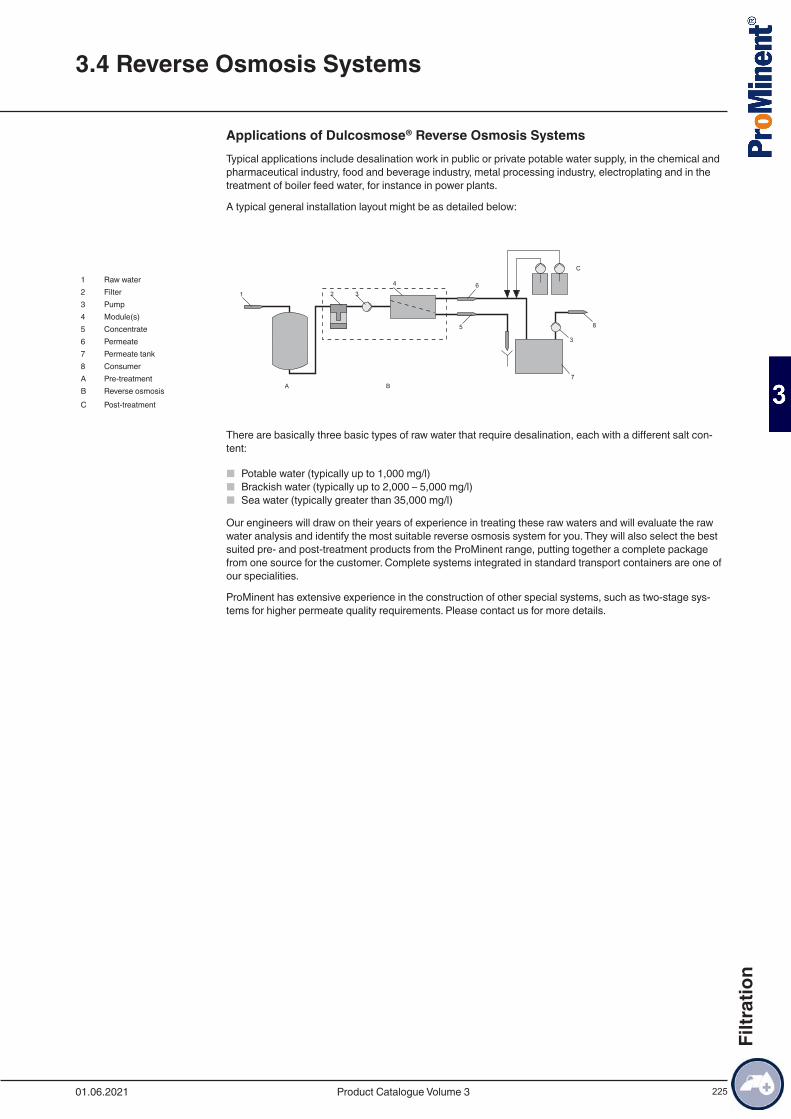
225
Applications of Dulcosmose® Reverse Osmosis SystemsTypical applications include desalination work in public or private potable water supply, in the chemical and pharmaceutical industry, food and beverage industry, metal processing industry, electroplating and in the treatment of boiler feed water, for instance in power plants.
A typical general installation layout might be as detailed below:
1 Raw water2 Filter3 Pump4 Module(s)5 Concentrate6 Permeate7 Permeate tank8 ConsumerA Pre-treatmentB Reverse osmosisC Post-treatment
There are basically three basic types of raw water that require desalination, each with a different salt con-tent:
■ Potable water (typically up to 1,000 mg/l) ■ Brackish water (typically up to 2,000 – 5,000 mg/l) ■ Sea water (typically greater than 35,000 mg/l)
Our engineers will draw on their years of experience in treating these raw waters and will evaluate the raw water analysis and identify the most suitable reverse osmosis system for you. They will also select the best suited pre- and post-treatment products from the ProMinent range, putting together a complete package from one source for the customer. Complete systems integrated in standard transport containers are one of our specialities.
ProMinent has extensive experience in the construction of other special systems, such as two-stage sys-tems for higher permeate quality requirements. Please contact us for more details.
3.4 Reverse Osmosis Systems
01.06.2021 Product Catalogue Volume 3
Filtr
atio
n
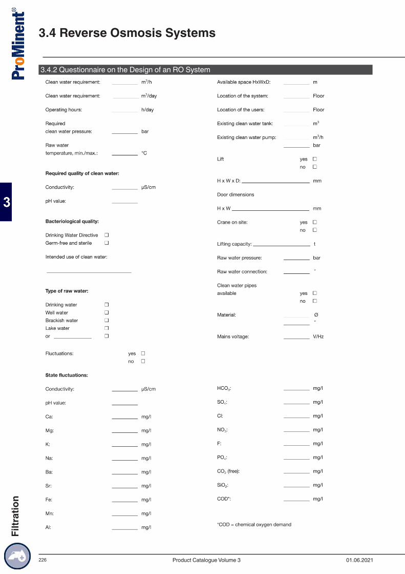
226
3.4.2 Questionnaire on the Design of an RO System
3.4 Reverse Osmosis Systems
01.06.2021Product Catalogue Volume 3
Filtr
atio
n
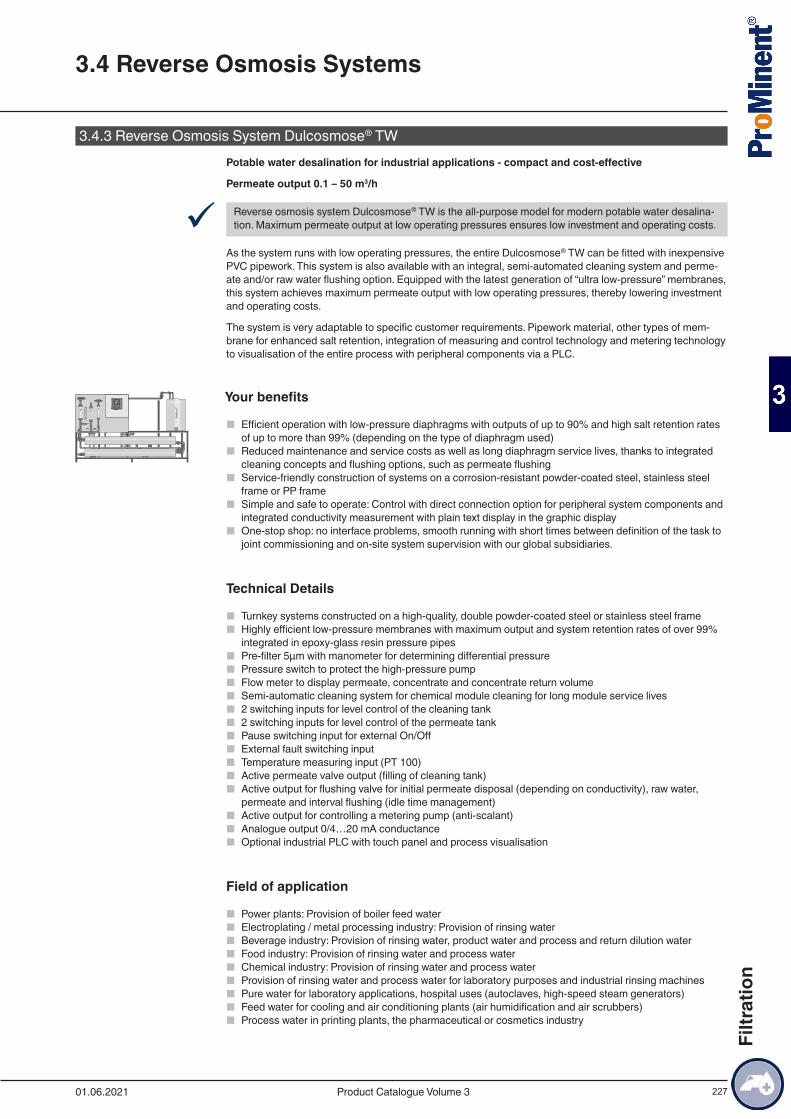
227
3.4.3 Reverse Osmosis System Dulcosmose® TWPotable water desalination for industrial applications - compact and cost-effective
Permeate output 0.1 – 50 m3/h
9 Reverse osmosis system Dulcosmose® TW is the all-purpose model for modern potable water desalina-tion. Maximum permeate output at low operating pressures ensures low investment and operating costs.
As the system runs with low operating pressures, the entire Dulcosmose® TW can be fitted with inexpensive PVC pipework. This system is also available with an integral, semi-automated cleaning system and perme-ate and/or raw water flushing option. Equipped with the latest generation of “ultra low-pressure” membranes, this system achieves maximum permeate output with low operating pressures, thereby lowering investment and operating costs.
The system is very adaptable to specific customer requirements. Pipework material, other types of mem-brane for enhanced salt retention, integration of measuring and control technology and metering technology to visualisation of the entire process with peripheral components via a PLC.
Your benefits
■ Efficient operation with low-pressure diaphragms with outputs of up to 90% and high salt retention rates of up to more than 99% (depending on the type of diaphragm used)
■ Reduced maintenance and service costs as well as long diaphragm service lives, thanks to integrated cleaning concepts and flushing options, such as permeate flushing
■ Service-friendly construction of systems on a corrosion-resistant powder-coated steel, stainless steel frame or PP frame
■ Simple and safe to operate: Control with direct connection option for peripheral system components and integrated conductivity measurement with plain text display in the graphic display
■ One-stop shop: no interface problems, smooth running with short times between definition of the task to joint commissioning and on-site system supervision with our global subsidiaries.
Technical Details
■ Turnkey systems constructed on a high-quality, double powder-coated steel or stainless steel frame ■ Highly efficient low-pressure membranes with maximum output and system retention rates of over 99%
integrated in epoxy-glass resin pressure pipes ■ Pre-filter 5µm with manometer for determining differential pressure ■ Pressure switch to protect the high-pressure pump ■ Flow meter to display permeate, concentrate and concentrate return volume ■ Semi-automatic cleaning system for chemical module cleaning for long module service lives ■ 2 switching inputs for level control of the cleaning tank ■ 2 switching inputs for level control of the permeate tank ■ Pause switching input for external On/Off ■ External fault switching input ■ Temperature measuring input (PT 100) ■ Active permeate valve output (filling of cleaning tank) ■ Active output for flushing valve for initial permeate disposal (depending on conductivity), raw water,
permeate and interval flushing (idle time management) ■ Active output for controlling a metering pump (anti-scalant) ■ Analogue output 0/4…20 mA conductance ■ Optional industrial PLC with touch panel and process visualisation
Field of application
■ Power plants: Provision of boiler feed water ■ Electroplating / metal processing industry: Provision of rinsing water ■ Beverage industry: Provision of rinsing water, product water and process and return dilution water ■ Food industry: Provision of rinsing water and process water ■ Chemical industry: Provision of rinsing water and process water ■ Provision of rinsing water and process water for laboratory purposes and industrial rinsing machines ■ Pure water for laboratory applications, hospital uses (autoclaves, high-speed steam generators) ■ Feed water for cooling and air conditioning plants (air humidification and air scrubbers) ■ Process water in printing plants, the pharmaceutical or cosmetics industry
3.4 Reverse Osmosis Systems
01.06.2021 Product Catalogue Volume 3
Filtr
atio
n
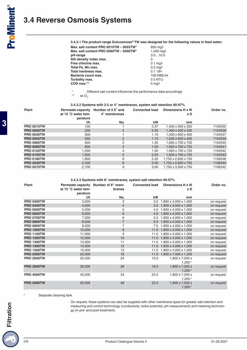
228
3.4.3.1 The product range Dulcosmose® TW was designed for the following values in feed water:Max. salt content PRO 0010TW – 0055TW* 650 mg/lMax. salt content PRO 0060TW – 5000TW* 1,000 mg/lpH-range 3.0…10.0Silt density index max. 3Free chlorine max. 0.1 mg/lTotal Fe, Mn max. 0.2 mg/lTotal hardness max. 0.1 °dHBacteria count max. 100 KBE/mlTurbidity max. 0.5 NTUCOD max.** 5 mg/l
* Different salt content influences the performance data accordingly** as O2
3.4.3.2 Systems with 2.5 or 4” membranes, system salt retention 90-97%Plant Permeate capacity
at 15 °C water tem-perature
Number of 2.5” and 4” membranes
Connected load Dimensions H x W x D
Order no.
l/h No. kW mm PRO 0010TW 100 1 0.37 1,400 x 500 x 320 1104535PRO 0020TW 200 2 0.55 1,400 x 500 x 320 1104536PRO 0030TW 300 1 1.10 1,500 x 600 x 400 1104537PRO 0055TW 550 2 1.10 1,500 x 600 x 400 1104539PRO 0060TW 600 2 1.50 1,650 x 700 x 720 1104540PRO 0090TW 900 3 1.50 1,650 x 700 x 720 1104541PRO 0120TW 1,200 4 1.50 1,650 x 700 x 720 1104542PRO 0150TW 1,500 5 2.20 1,650 x 700 x 720 1104543PRO 0180TW 1,800 6 2.20 1,750 x 2,600 x 750 1106338PRO 0240TW 2,400 8 3.00 1,750 x 2,600 x 750 1106340PRO 0270TW 2,700 9 3.00 1,750 x 3,500 x 750 1106342
3.4.3.3 Systems with 8” membranes, system salt retention 90-97%Plant Permeate capacity
at 15 °C water tem-perature
Number of 8″ mem-branes
Connected load Dimensions H x W x D
Order no.
l/h No. kW mm PRO 0300TW 3,000 3 3.0 1,800 x 4,000 x 1,000 on requestPRO 0400TW 4,000 4 3.0 1,800 x 3,000 x 1,000 on requestPRO 0500TW 5,000 5 4.0 1,800 x 4,000 x 1,000 on requestPRO 0600TW 6,000 6 4.0 1,800 x 4,000 x 1,000 on requestPRO 0700TW 7,000 6 5.5 1,800 x 4,000 x 1,000 on requestPRO 0800TW 8,000 7 5.5 1,800 x 4,000 x 1,000 on requestPRO 0900TW 9,000 7 7.5 1,800 x 4,000 x 1,000 on requestPRO 1000TW 10,000 8 11.0 1,800 x 3,000 x 1,000 on requestPRO 1100TW 11,000 9 11.0 1,800 x 4,000 x 1,000 on requestPRO 1200TW 12,000 10 11.0 1,800 x 4,000 x 1,000 on requestPRO 1300TW 13,000 11 11.0 1,800 x 4,000 x 1,000 on requestPRO 1400TW 14,000 12 11.0 1,800 x 4,000 x 1,000 on requestPRO 1500TW 15,000 12 11.0 1,800 x 4,000 x 1,000 on requestPRO 2000TW 20,000 18 11.0 1,800 x 7,000 x 1,200 on requestPRO 2500TW 25,000 24 15.0 1,800 x 7,000 x
1,200 *on request
PRO 3000TW 30,000 28 18.5 1,800 x 7,000 x 1,200 *
on request
PRO 4000TW 40,000 34 22.0 1,800 x 7,000 x 1,200 *
on request
PRO 5000TW 50,000 48 22.0 1,800 x 7,000 x 1,200 *
on request
* Separate cleaning tank
On request, these systems can also be supplied with other membrane types for greater salt retention and measuring and control technology (conductivity, redox potential, pH measurement) and metering technolo-gy (in pre- and post-treatment).
3.4 Reverse Osmosis Systems
01.06.2021Product Catalogue Volume 3
Filtr
atio
n
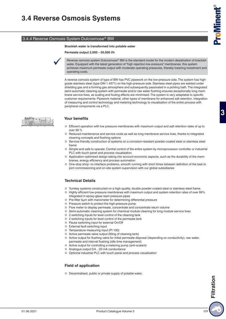
229
3.4.4 Reverse Osmosis System Dulcosmose® BW Brackish water is transformed into potable water
Permeate output 2,000 – 50,000 l/h
9 Reverse osmosis system Dulcosmose® BW is the standard model for the modern desalination of brackish water. Equipped with the latest generation of “high rejection low-pressure” membranes, this system achieves maximum permeate output with moderate operating pressures, thereby lowering investment and operating costs.
A reverse osmosis system of type of BW has PVC pipework on the low-pressure side. The system has high-grade stainless steel (type DIN 1.4571) on the high-pressure side. Stainless steel pipes are welded under shielding gas and a forming gas atmosphere and subsequently passivated in a pickling bath. The integrated semi-automatic cleaning system with permeate and/or raw water flushing ensures exceptionally long mem-brane service lives, as scaling and fouling effects are minimised. The system is very adaptable to specific customer requirements. Pipework material, other types of membrane for enhanced salt retention, integration of measuring and control technology and metering technology to visualisation of the entire process with peripheral components via a PLC.
Your benefits
■ Efficient operation with low pressure membranes with maximum output and salt retention rates of up to over 99 %
■ Reduced maintenance and service costs as well as long membrane service lives, thanks to integrated cleaning concepts and flushing options
■ Service-friendly construction of systems on a corrosion-resistant powder-coated steel or stainless steel frame
■ Simple and safe to operate: Central control of the entire system by microprocessor controller or industrial PLC with touch panel and process visualisation.
■ Application-optimised design taking into account economic aspects, such as the durability of the mem-branes, energy efficiency and process automation
■ One-stop shop: no interface problems, smooth running with short times between definition of the task to joint commissioning and on-site system supervision with our global subsidiaries
Technical Details
■ Turnkey systems constructed on a high-quality, double powder-coated steel or stainless steel frame. ■ Highly efficient low-pressure membranes with maximum output and system retention rates of over 99%
integrated in epoxy-glass resin pressure pipes ■ Pre-filter 5µm with manometer for determining differential pressure ■ Pressure switch to protect the high-pressure pump ■ Flow meter to display permeate, concentrate and concentrate return volume ■ Semi-automatic cleaning system for chemical module cleaning for long module service lives ■ 2 switching inputs for level control of the cleaning tank ■ 2 switching inputs for level control of the permeate tank ■ Pause switching input for external On/Off ■ External fault switching input ■ Temperature measuring input (Pt 100) ■ Active permeate valve output (filling of cleaning tank) ■ Active output for flushing valve for initial permeate disposal (depending on conductivity), raw water,
permeate and interval flushing (idle time management) ■ Active output for controlling a metering pump (anti-scalant) ■ Analogue output 0/4…20 mA conductance ■ Optional industrial PLC with touch panel and process visualisation
Field of application
■ Decentralised, public or private supply of potable water.
356564.5
356564.
5
356564.5
356563.7 356563.7
3.4 Reverse Osmosis Systems
01.06.2021 Product Catalogue Volume 3
Filtr
atio
n
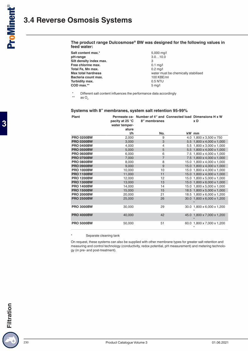
230
The product range Dulcosmose® BW was designed for the following values in feed water:Salt content max.* 5,000 mg/lpH-range 3.0…10.0Silt density index max. 3Free chlorine max. 0.1 mg/lTotal Fe, Mn max. 0.2 mg/lMax total hardness water must be chemically stabilisedBacteria count max. 100 KBE/mlTurbidity max. 0.5 NTUCOD max.** 5 mg/l
* Different salt content influences the performance data accordingly** as O2
Systems with 8” membranes, system salt retention 95-99%Plant Permeate ca-
pacity at 25 °C water temper-
ature
Number of 4″ and 8″ membranes
Connected load Dimensions H x W x D
l/h No. kW mmPRO 0200BW 2,000 9 4.0 1,800 x 3,500 x 750PRO 0300BW 3,000 3 5.5 1,800 x 4,000 x 1,000PRO 0400BW 4,000 4 5.5 1,800 x 3,000 x 1,000PRO 0500BW 5,000 5 5.5 1,800 x 4,000 x 1,000PRO 0600BW 6,000 6 7.5 1,800 x 4,000 x 1,000PRO 0700BW 7,000 7 7.5 1,800 x 4,000 x 1,000PRO 0800BW 8,000 8 15.0 1,800 x 4,000 x 1,000PRO 0900BW 9,000 9 15.0 1,800 x 4,000 x 1,000PRO 1000BW 10,000 10 15.0 1,800 x 4,000 x 1,000PRO 1100BW 11,000 11 15.0 1,800 x 4,000 x 1,000PRO 1200BW 12,000 12 15.0 1,800 x 5,000 x 1,000PRO 1300BW 13,000 13 15.0 1,800 x 6,000 x 1,000PRO 1400BW 14,000 14 15.0 1,800 x 5,000 x 1,000PRO 1500BW 15,000 15 18.5 1,800 x 5,000 x 1,000PRO 2000BW 20,000 21 18.5 1,800 x 6,000 x 1,200PRO 2500BW 25,000 26 30.0 1,800 x 6,000 x 1,200
*PRO 3000BW 30,000 29 30.0 1,800 x 6,000 x 1,200
*PRO 4000BW 40,000 42 45.0 1,800 x 7,000 x 1,200
*PRO 5000BW 50,000 51 60.0 1,800 x 7,000 x 1,200
*
* Separate cleaning tank
On request, these systems can also be supplied with other membrane types for greater salt retention and measuring and control technology (conductivity, redox potential, pH measurement) and metering technolo-gy (in pre- and post-treatment).
3.4 Reverse Osmosis Systems
01.06.2021Product Catalogue Volume 3
Filtr
atio
n

231
3.4.5 Reverse Osmosis System Dulcosmose® SW Salt water is transformed into drinking water.
Permeate output 780 – 29,000 l/h
9 The reverse osmosis system Dulcosmose® SW is the standard model for modern desalination of salt wa-ter. Equipped with the latest generation of “high rejection low-pressure” membranes, this system achieves maximum permeate output with moderate operating pressures, thereby lowering investment and operating costs.
A reverse osmosis system of type of SW has PVC pipework on the low-pressure side. The high-pressure side of the system has a potable water-compatible, highly corrosion-resistant inner seal due to the high NaCI content. The integrated semi-automatic cleaning system with permeate and/or raw water flushing en-sures exceptionally long membrane service lives, as scaling and fouling effects are minimised. The system can be adapted with ease to specific customer requirements. Pipework material, other types of membrane for enhanced salt retention, integration of measuring and control technology and metering technology to visualisation of the entire process with peripheral components via a PLC. Everything can be selected at random. Optional for all systems: They can be fitted with a system for energy recovery from the concentrate flow. The latest generation of what are known as pressure controllers is used.
Your benefits
■ Integrated energy recovery system based on state-of-the-art pressure controllers ■ Efficient operation with low pressure membranes with outputs of up to 50% and high salt retention rates
of up to over 99% ■ Reduced maintenance and service costs as well as long membrane service lives, thanks to integrated
cleaning concepts and flushing options ■ Service-friendly construction of systems on a corrosion-resistant powder-coated steel or stainless steel
frame ■ Simple and safe to operate: Central control of the entire system by microprocessor controller or industrial
PLC with touch panel and process visualisation ■ Application-optimised design taking into account economic aspects, such as the durability of the mem-
branes, energy efficiency and process automation ■ One-stop shop: no interface problems, smooth running with short times between definition of the task to
joint commissioning and on-site system supervision with our global subsidiaries
Technical Details
■ Turnkey systems constructed on a high-quality, double powder-coated steel or stainless steel frame ■ Highly efficient low-pressure membranes with maximum output and system retention rates of over 99%
integrated in epoxy-glass resin pressure pipes ■ Pre-filter 5µm with manometer for determining differential pressure ■ Pressure switch to protect the high-pressure pump ■ Flow meter to display permeate and concentrate volume ■ Semi-automatic cleaning system for chemical module cleaning for long module service lives ■ Central PLC of the entire system and peripheral components, adapted to customer requirements
Field of application
■ Decentralised, public or private supply of potable water.
3.4 Reverse Osmosis Systems
01.06.2021 Product Catalogue Volume 3
Filtr
atio
n
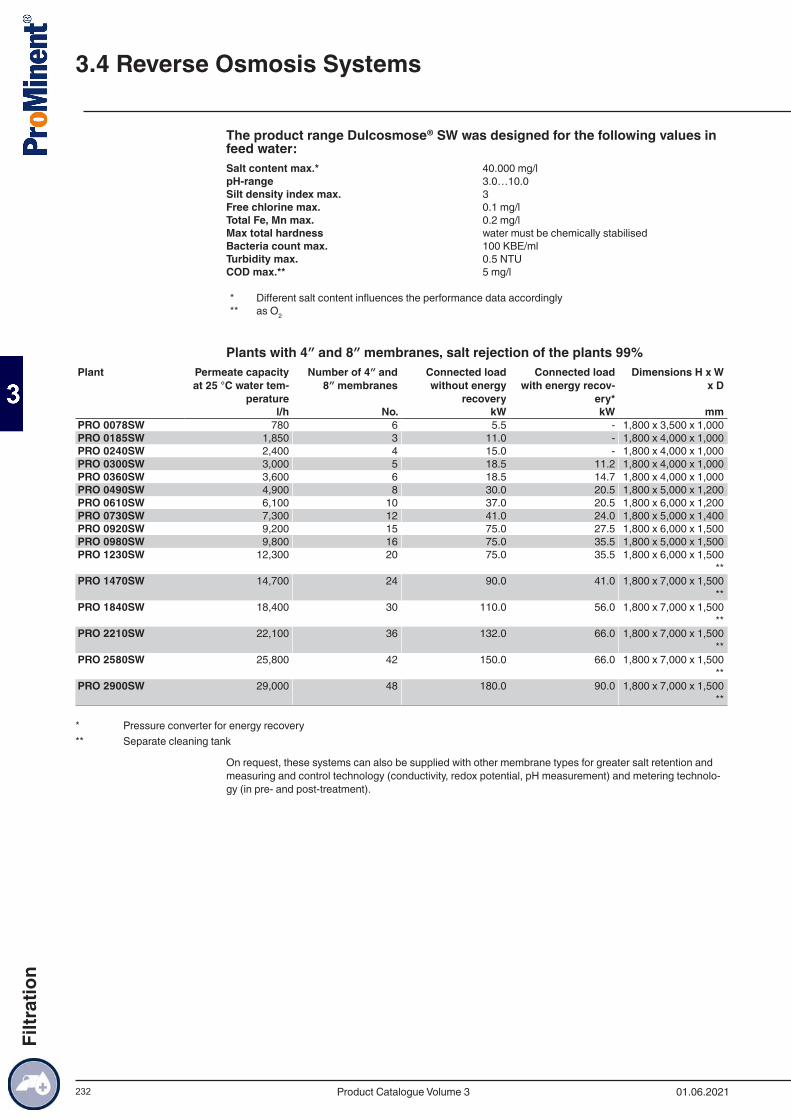
232
The product range Dulcosmose® SW was designed for the following values in feed water:Salt content max.* 40.000 mg/lpH-range 3.0…10.0Silt density index max. 3Free chlorine max. 0.1 mg/lTotal Fe, Mn max. 0.2 mg/lMax total hardness water must be chemically stabilisedBacteria count max. 100 KBE/mlTurbidity max. 0.5 NTUCOD max.** 5 mg/l
* Different salt content influences the performance data accordingly** as O2
Plants with 4″ and 8″ membranes, salt rejection of the plants 99%Plant Permeate capacity
at 25 °C water tem-perature
Number of 4″ and 8″ membranes
Connected load without energy
recovery
Connected load with energy recov-
ery*
Dimensions H x W x D
l/h No. kW kW mmPRO 0078SW 780 6 5.5 - 1,800 x 3,500 x 1,000PRO 0185SW 1,850 3 11.0 - 1,800 x 4,000 x 1,000PRO 0240SW 2,400 4 15.0 - 1,800 x 4,000 x 1,000PRO 0300SW 3,000 5 18.5 11.2 1,800 x 4,000 x 1,000PRO 0360SW 3,600 6 18.5 14.7 1,800 x 4,000 x 1,000PRO 0490SW 4,900 8 30.0 20.5 1,800 x 5,000 x 1,200PRO 0610SW 6,100 10 37.0 20.5 1,800 x 6,000 x 1,200PRO 0730SW 7,300 12 41.0 24.0 1,800 x 5,000 x 1,400PRO 0920SW 9,200 15 75.0 27.5 1,800 x 6,000 x 1,500PRO 0980SW 9,800 16 75.0 35.5 1,800 x 5,000 x 1,500PRO 1230SW 12,300 20 75.0 35.5 1,800 x 6,000 x 1,500
**PRO 1470SW 14,700 24 90.0 41.0 1,800 x 7,000 x 1,500
**PRO 1840SW 18,400 30 110.0 56.0 1,800 x 7,000 x 1,500
**PRO 2210SW 22,100 36 132.0 66.0 1,800 x 7,000 x 1,500
**PRO 2580SW 25,800 42 150.0 66.0 1,800 x 7,000 x 1,500
**PRO 2900SW 29,000 48 180.0 90.0 1,800 x 7,000 x 1,500
**
* Pressure converter for energy recovery** Separate cleaning tank
On request, these systems can also be supplied with other membrane types for greater salt retention and measuring and control technology (conductivity, redox potential, pH measurement) and metering technolo-gy (in pre- and post-treatment).
3.4 Reverse Osmosis Systems
01.06.2021Product Catalogue Volume 3
Filtr
atio
n
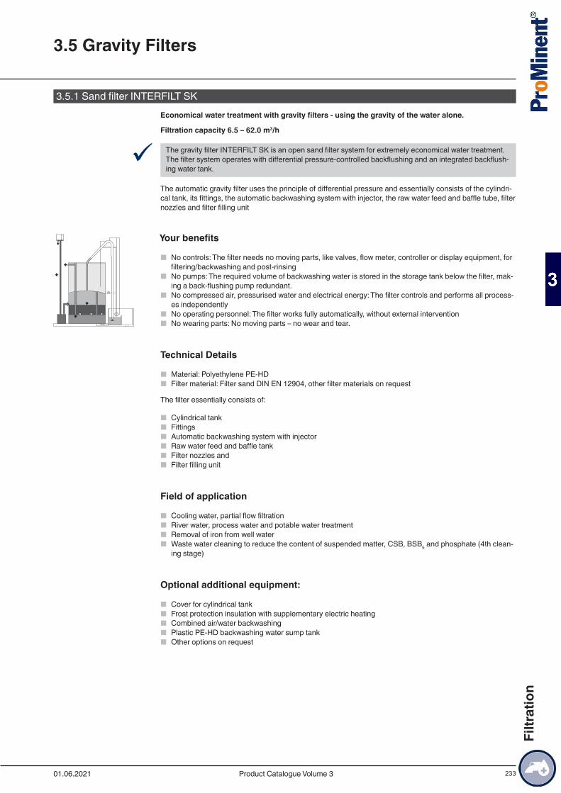
233
3.5.1 Sand filter INTERFILT SKEconomical water treatment with gravity filters - using the gravity of the water alone.
Filtration capacity 6.5 – 62.0 m3/h
9 The gravity filter INTERFILT SK is an open sand filter system for extremely economical water treatment. The filter system operates with differential pressure-controlled backflushing and an integrated backflush-ing water tank.
The automatic gravity filter uses the principle of differential pressure and essentially consists of the cylindri-cal tank, its fittings, the automatic backwashing system with injector, the raw water feed and baffle tube, filter nozzles and filter filling unit
Your benefits
■ No controls: The filter needs no moving parts, like valves, flow meter, controller or display equipment, for filtering/backwashing and post-rinsing
■ No pumps: The required volume of backwashing water is stored in the storage tank below the filter, mak-ing a back-flushing pump redundant.
■ No compressed air, pressurised water and electrical energy: The filter controls and performs all process-es independently
■ No operating personnel: The filter works fully automatically, without external intervention ■ No wearing parts: No moving parts – no wear and tear.
Technical Details
■ Material: Polyethylene PE-HD ■ Filter material: Filter sand DIN EN 12904, other filter materials on request
The filter essentially consists of:
■ Cylindrical tank ■ Fittings ■ Automatic backwashing system with injector ■ Raw water feed and baffle tank ■ Filter nozzles and ■ Filter filling unit
Field of application
■ Cooling water, partial flow filtration ■ River water, process water and potable water treatment ■ Removal of iron from well water ■ Waste water cleaning to reduce the content of suspended matter, CSB, BSB5 and phosphate (4th clean-
ing stage)
Optional additional equipment:
■ Cover for cylindrical tank ■ Frost protection insulation with supplementary electric heating ■ Combined air/water backwashing ■ Plastic PE-HD backwashing water sump tank ■ Other options on request
3.5 Gravity Filters
01.06.2021 Product Catalogue Volume 3
Filtr
atio
n
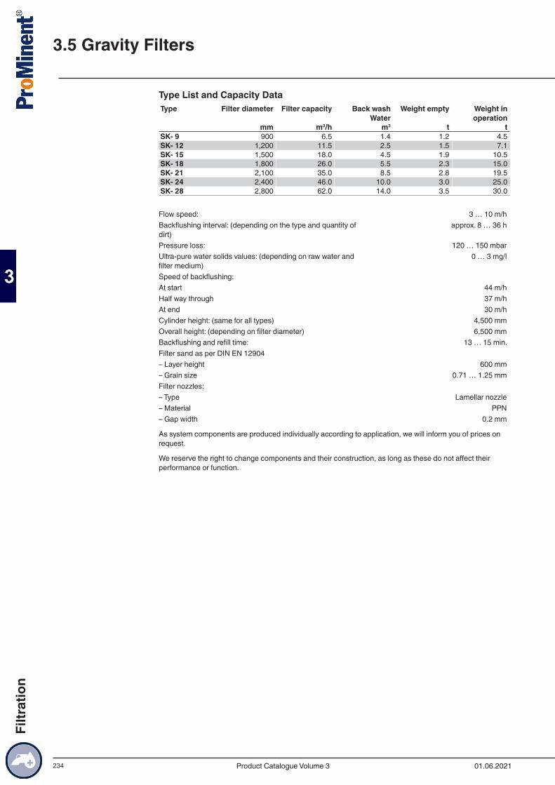
234
Type List and Capacity DataType Filter diameter Filter capacity Back wash
WaterWeight empty Weight in
operation mm m3/h m3 t tSK- 9 900 6.5 1.4 1.2 4.5SK- 12 1,200 11.5 2.5 1.5 7.1SK- 15 1,500 18.0 4.5 1.9 10.5SK- 18 1,800 26.0 5.5 2.3 15.0SK- 21 2,100 35.0 8.5 2.8 19.5SK- 24 2,400 46.0 10.0 3.0 25.0SK- 28 2,800 62.0 14.0 3.5 30.0
Flow speed: 3 … 10 m/hBackflushing interval: (depending on the type and quantity of dirt)
approx. 8 … 36 h
Pressure loss: 120 … 150 mbarUltra-pure water solids values: (depending on raw water and filter medium)
0 … 3 mg/l
Speed of backflushing:At start 44 m/hHalf way through 37 m/hAt end 30 m/hCylinder height: (same for all types) 4,500 mmOverall height: (depending on filter diameter) 6,500 mmBackflushing and refill time: 13 … 15 min.Filter sand as per DIN EN 12904– Layer height 600 mm– Grain size 0.71 … 1.25 mmFilter nozzles:– Type Lamellar nozzle– Material PPN– Gap width 0.2 mm
As system components are produced individually according to application, we will inform you of prices on request.
We reserve the right to change components and their construction, as long as these do not affect their performance or function.
3.5 Gravity Filters
01.06.2021Product Catalogue Volume 3
Filtr
atio
n

You can find our individual catalogue volumes for download or online browsing at
www.prominent.com/en/product-catalogue
Do you need an overview of our entire product range?
Then we would recommend our product overview.
www.prominent.com/en/productoverview
Metering Technology
Measuring, Control and Sensor Technology
Water Treatment and Disinfection
Your digital reference source. Wherever you want. Whenever you want.Product catalogue 2021
Groundbreaking diversity: ProMinent 2021.
Our product catalogue is available in three individual volumes.