
Focus on Data Entities - MDPI
34
applied sciences Article Linguistic Patterns and Linguistic Styles for Requirements Specification: Focus on Data Entities Alberto Rodrigues da Silva 1, * and Dušan Savi´ c 2 Citation: da Silva, A.R.; Savi´ c, D. Linguistic Patterns and Linguistic Styles for Requirements Specification: Focus on Data Entities. Appl. Sci. 2021, 11, 4119. https://doi.org/ 10.3390/app11094119 Academic Editor: Francisco García-Sánchez Received: 6 April 2021 Accepted: 27 April 2021 Published: 30 April 2021 Publisher’s Note: MDPI stays neutral with regard to jurisdictional claims in published maps and institutional affil- iations. Copyright: © 2021 by the authors. Licensee MDPI, Basel, Switzerland. This article is an open access article distributed under the terms and conditions of the Creative Commons Attribution (CC BY) license (https:// creativecommons.org/licenses/by/ 4.0/). 1 INESC-ID, Instituto Superior Técnico, Universidade de Lisboa, 1000-029 Lisbon, Portugal 2 Faculty of Organizational Sciences, University in Belgrade, 11000 Belgrade, Serbia; [email protected] * Correspondence: [email protected] Abstract: Requirements specification includes technical concerns of an information system and is used throughout its life cycle. It allows for sharing the vision of the system among stakeholders and facilitates its development and operation processes. Natural languages are the most common form of requirements representation, however, they also exhibit characteristics that often introduce quality problems, such as inconsistency, incompleteness, and ambiguousness. This paper adopts the notions of linguistic pattern and linguistic style and discusses their relevance to produce better technical documentation. It focuses on the textual specification of data entities, which are elements commonly referred to throughout different types of requirements, like use cases, user stories, or functional requirements. This paper discusses how to textually represent the following elements: data entity, attribute, data type, data entity constraint, attribute constraint, and even cluster of data entities. This paper shows concrete examples and supports the discussion with three linguistic styles, represented by a rigorous requirements specification language and two informal controlled natural languages, one with a more compact and another with a more verbose, expressive, and complete representation. We analyzed how other languages cope with the representation of these data entity elements and complemented that analysis and comparison based on the PENS classification scheme. We conducted a pilot evaluation session with nineteen professional subjects who participated and provided encouraging feedback, with positive scores in all the analyzed dimensions. From this feedback, we preliminarily conclude that the adoption of these linguistic patterns would help to produce better requirements specifications written more systematically and consistently. Keywords: requirements specification; linguistic pattern; linguistic style; controlled natural language; data entities; domain model 1. Introduction Requirements engineering (RE) is a discipline that intends to provide a shared vision and understanding of socio-technical systems among the involved stakeholders throughout their life-cycle [1,2]. The negative consequences of ignoring these early RE activities are extensively reported and discussed in the literature [3,4]. A system requirements specification (SRS, or just “requirements specification”) is an im- portant document that structures the concerns of such systems from the RE perspective. In many cases, these systems are only focused on software applications and respective databases, while in other circumstances, they may involve other elements and concerns. A good SRS offers several benefits such as reported in the literature [2,5,6]: it contributes to the establishment of an agreement and business contract between customers and suppliers; provides a common ground for supporting the project budget and schedule estimation and plan; supports the project scope validation and verification and may support deployment and future maintenance activities. It is usually recommended that an SRS be defined accordingly as a predefined SRS template as well as a set of recommendations on how to customize and use it. An SRS template prescribes a given document structure with Appl. Sci. 2021, 11, 4119. https://doi.org/10.3390/app11094119 https://www.mdpi.com/journal/applsci
-
Upload
khangminh22 -
Category
Documents
-
view
5 -
download
0
Transcript of Focus on Data Entities - MDPI
applied sciences
Article
Linguistic Patterns and Linguistic Styles for RequirementsSpecification: Focus on Data Entities
Alberto Rodrigues da Silva 1,* and Dušan Savic 2
�����������������
Citation: da Silva, A.R.; Savic, D.
Linguistic Patterns and Linguistic
Styles for Requirements Specification:
Focus on Data Entities. Appl. Sci.
2021, 11, 4119. https://doi.org/
10.3390/app11094119
Academic Editor:
Francisco García-Sánchez
Received: 6 April 2021
Accepted: 27 April 2021
Published: 30 April 2021
Publisher’s Note: MDPI stays neutral
with regard to jurisdictional claims in
published maps and institutional affil-
iations.
Copyright: © 2021 by the authors.
Licensee MDPI, Basel, Switzerland.
This article is an open access article
distributed under the terms and
conditions of the Creative Commons
Attribution (CC BY) license (https://
creativecommons.org/licenses/by/
4.0/).
1 INESC-ID, Instituto Superior Técnico, Universidade de Lisboa, 1000-029 Lisbon, Portugal2 Faculty of Organizational Sciences, University in Belgrade, 11000 Belgrade, Serbia; [email protected]* Correspondence: [email protected]
Abstract: Requirements specification includes technical concerns of an information system and isused throughout its life cycle. It allows for sharing the vision of the system among stakeholdersand facilitates its development and operation processes. Natural languages are the most commonform of requirements representation, however, they also exhibit characteristics that often introducequality problems, such as inconsistency, incompleteness, and ambiguousness. This paper adoptsthe notions of linguistic pattern and linguistic style and discusses their relevance to produce bettertechnical documentation. It focuses on the textual specification of data entities, which are elementscommonly referred to throughout different types of requirements, like use cases, user stories, orfunctional requirements. This paper discusses how to textually represent the following elements:data entity, attribute, data type, data entity constraint, attribute constraint, and even cluster of dataentities. This paper shows concrete examples and supports the discussion with three linguistic styles,represented by a rigorous requirements specification language and two informal controlled naturallanguages, one with a more compact and another with a more verbose, expressive, and completerepresentation. We analyzed how other languages cope with the representation of these data entityelements and complemented that analysis and comparison based on the PENS classification scheme.We conducted a pilot evaluation session with nineteen professional subjects who participated andprovided encouraging feedback, with positive scores in all the analyzed dimensions. From thisfeedback, we preliminarily conclude that the adoption of these linguistic patterns would help toproduce better requirements specifications written more systematically and consistently.
Keywords: requirements specification; linguistic pattern; linguistic style; controlled natural language;data entities; domain model
1. Introduction
Requirements engineering (RE) is a discipline that intends to provide a shared visionand understanding of socio-technical systems among the involved stakeholders throughouttheir life-cycle [1,2]. The negative consequences of ignoring these early RE activities areextensively reported and discussed in the literature [3,4].
A system requirements specification (SRS, or just “requirements specification”) is an im-portant document that structures the concerns of such systems from the RE perspective.In many cases, these systems are only focused on software applications and respectivedatabases, while in other circumstances, they may involve other elements and concerns.A good SRS offers several benefits such as reported in the literature [2,5,6]: it contributes tothe establishment of an agreement and business contract between customers and suppliers;provides a common ground for supporting the project budget and schedule estimation andplan; supports the project scope validation and verification and may support deploymentand future maintenance activities. It is usually recommended that an SRS be definedaccordingly as a predefined SRS template as well as a set of recommendations on howto customize and use it. An SRS template prescribes a given document structure with
Appl. Sci. 2021, 11, 4119. https://doi.org/10.3390/app11094119 https://www.mdpi.com/journal/applsci

Appl. Sci. 2021, 11, 4119 2 of 34
supplementary practical guidelines. In general, these templates recommend the use ofvarious views and constructs (e.g., actors, use cases, user stories) that might be considered“modular artifacts” in the sense of their definition and reuse. Because there are dependen-cies among these constructs, some authors argue that it is essential to minimize or preventthem, and some templates give support in this respect [7].
On the other hand, and because both technical and business stakeholders commonlyuse SRSs, they tend to be specified mostly in natural languages [8]. Indeed, naturallanguages reach an adequate communication level as they are flexible and universal, andhumans are proficient at using them to communicate with each other. Additionally, theyhave minimal adoption resistance as a requirements documentation technique. However,they also exhibit some intrinsic features that frequently put them as the source of manyquality problems such as inconsistency, incompleteness, and ambiguousness [1,2,9,10].
Due to these problems, some authors have proposed practical recommendations forbetter writing requirements [1,11–15], including general guidelines like the following: thelanguage should be simple, clear, and precise; it should follow a standardized format togive coherence and uniformity to all sentences; the sentences should be simple, short, andwritten in an affirmative and active voice style; the vocabulary should be limited. However,these recommendations are better supported by the guidance of controlled natural languages(further information in Section 2).
In this scope, linguistic patterns are grammatical rules that allow their users to writecorrectly in a common language (additional details in Section 3). From a linguistic per-spective, grammar is a collection of rules, but also a set of blueprints that guide speakersin producing more comprehensible and predictable sentences [16]. Despite the diversityof terms found in the literature—for instance, “syntactic requirements pattern” [1], “re-quirements template” [17], or “standardized format” [15]—we adopt in this paper theterms “linguistic pattern” and “linguistic style” as discussed originally by Silva to mean,respectively, the definition and the representation of such grammatical rules [18]. In thatpaper, Silva focused on business-level constructs, namely: glossary terms, stakeholders,business goals, processes, events, and flows [18]. We also use the terms “linguistic style”and “writing style” as synonyms, which provide concrete and consistent representation ofa given pattern. Although being inspired by that earlier work, this paper is unique becauseit is focused on the textual specification of data entities, and this was not addressed in thatformer work or by others as discussed in the related work (see Section 5).
Data entities denote conceptual or domain objects of the system-of-interest and theyare commonly referred to in various types of requirements like use cases, user stories,functional, or even informal requirements. As suggested in Figure 1, data entities andassociated elements (e.g., attributes, attribute values, enumerations of concrete values,data constraints) are usually referred to in requirements scattered throughout the text and,unfortunately, represented inconsistently with different writing styledsxxxxxxxxxxfs. Forinstance, as showed in Figure 1, the names “Products” (in sentence S3) and “product” (inS5) should refer to the same data entity; or “rate type” (in S4) and “rate” (in S4 and S4) arerepresented inconsistently and ambiguously because they should denote the same attribute.
In requirements specifications, data entities can be defined in a general way (e.g., byonly referring to their names) or more exhaustively by enumerating their attributes, types,and even constraints. It might need to also specify the data entity’s attributes by onlydefining their names or also by specifying their types and constraints. An attribute typemight be just a predefined value, like Integer, Double, String, Date, Boolean, or still involvedata enumeration or customized types. Additionally, an attribute constraint might definethat the attribute shall be unique, not null, a foreign key to another data entity, or even acustomized check constraint.

Appl. Sci. 2021, 11, 4119 3 of 34Appl. Sci. 2021, 11, x FOR PEER REVIEW 3 of 34
Figure 1. Example of informal requirements with data entities and other related elements.
In requirements specifications, data entities can be defined in a general way (e.g., by only referring to their names) or more exhaustively by enumerating their attributes, types, and even constraints. It might need to also specify the data entity’s attributes by only de-fining their names or also by specifying their types and constraints. An attribute type might be just a predefined value, like Integer, Double, String, Date, Boolean, or still in-volve data enumeration or customized types. Additionally, an attribute constraint might define that the attribute shall be unique, not null, a foreign key to another data entity, or even a customized check constraint.
The key contribution of this paper is the proposal and discussion of an integrated set of linguistic patterns, which allow requirements engineers and product designers to write systematically and consistently data related aspects commonly found in requirements specifications, including data entities, attributes, related constraints, and even clusters of data entities, if relevant. To support the discussion, the application of these linguistic pat-terns is showed with a simple yet illustrative example, represented according to different linguistic or writing styles, namely the RSL, a rigorous requirements specification lan-guage, and two informal controlled natural languages, the CNL-A and the CNL-B.
Despite being significant, it is not in the scope of this paper to discuss other linguistic patterns and related concepts such as use cases, user stories, or functional requirements. Still, it is out of the scope to discuss approaches that exist to transform text specifications of data entities into domain models (e.g., represented with visual notations like ER dia-grams [19,20] or UML class diagrams [21]), ontologies (e.g., formally represented with OWL, which is a family of knowledge representation languages [22,23]) or even system’s database schemas (commonly represented with the SQL language [24]), and vice-versa. These aspects can be considered for future work as the foundation for the design of an intermediate language (IL), that would support automatic transformations from natural language to IL sentences, e.g., using NLP (natural language processing) techniques [10] and, on the other hand, from IL to visual models or other representations (such as ontol-ogies) using model-driven techniques [25,26]. Some of these aspects were surveyed for example by Bozyiğit et al. [27], Bork et al. [28], Schön et al. [29], and Cabot [30].
This paper is structured into seven sections. Section 2 introduces the relevance of controlled natural languages to the writing of requirement specifications and introduces the languages used in this research: CNL-A, CNL-B, and RSL. Section 3 defines the core notions of linguistic pattern and linguistic style. Section 4 discusses the proposed data entities’ linguistic patterns and supports the debate with an easy-to-understand running example. Section 5 refers to and discusses the related work. Section 6 presents the evalu-ation of the proposed linguistic patterns and styles conducted with a pilot user session.
Figure 1. Example of informal requirements with data entities and other related elements.
The key contribution of this paper is the proposal and discussion of an integratedset of linguistic patterns, which allow requirements engineers and product designers towrite systematically and consistently data related aspects commonly found in requirementsspecifications, including data entities, attributes, related constraints, and even clustersof data entities, if relevant. To support the discussion, the application of these linguisticpatterns is showed with a simple yet illustrative example, represented according to differentlinguistic or writing styles, namely the RSL, a rigorous requirements specification language,and two informal controlled natural languages, the CNL-A and the CNL-B.
Despite being significant, it is not in the scope of this paper to discuss other linguisticpatterns and related concepts such as use cases, user stories, or functional requirements.Still, it is out of the scope to discuss approaches that exist to transform text specificationsof data entities into domain models (e.g., represented with visual notations like ER di-agrams [19,20] or UML class diagrams [21]), ontologies (e.g., formally represented withOWL, which is a family of knowledge representation languages [22,23]) or even system’sdatabase schemas (commonly represented with the SQL language [24]), and vice-versa.These aspects can be considered for future work as the foundation for the design of anintermediate language (IL), that would support automatic transformations from naturallanguage to IL sentences, e.g., using NLP (natural language processing) techniques [10] and,on the other hand, from IL to visual models or other representations (such as ontologies)using model-driven techniques [25,26]. Some of these aspects were surveyed for exampleby Bozyigit et al. [27], Bork et al. [28], Schön et al. [29], and Cabot [30].
This paper is structured into seven sections. Section 2 introduces the relevance ofcontrolled natural languages to the writing of requirement specifications and introduces thelanguages used in this research: CNL-A, CNL-B, and RSL. Section 3 defines the core notionsof linguistic pattern and linguistic style. Section 4 discusses the proposed data entities’linguistic patterns and supports the debate with an easy-to-understand running example.Section 5 refers to and discusses the related work. Section 6 presents the evaluation of theproposed linguistic patterns and styles conducted with a pilot user session. Lastly, Section 7presents the conclusion and discusses open issues. In Addition, Appendix A describes therunning example used in Section 4 and includes a draft representation of that example withthe discussed writing styles as well as with a UML class diagram. Appendix B summarizesthe linguistic patterns, their recommended vocabulary, and provides a specification of thelinguistic patterns represented with the CNL-B notation.
2. Controlled Natural Languages
The specification of requirements based on natural languages is very expressive,easy to be written and read by humans, but not very precise because natural languages
Appl. Sci. 2021, 11, 4119 4 of 34
are ambiguous and inconsistent by nature and hard to be automatically manipulated bycomputers [31]. The usage of formal language methods could overcome these problems [32].However, this only addresses part of the question due to the difficulty in applying them intonot-so-critical systems because they require specialized training and are time-consuming.In the attempt to get the best from both worlds, i.e., the familiarity of natural language andthe rigorousness of formal language, some approaches have proposed controlled naturallanguages, which are engineered to resemble natural languages [33].
A controlled natural language (CNL) defines a constrained use of a natural language’sgrammar (syntax) and a set of terms (comprising the semantics of these terms) to beused in the constrained grammar [1,2]. The adoption of CNLs delivers the followingbenefits: CNL sentences are easy to understand since they are like sentences in naturallanguage. However, they are less ambiguous than expressions in natural language sincethey have a simplified grammar and a predefined vocabulary with precise semantics; andare semantically correct and can be computational manipulated since they may have aformal grammar and predefined terms.
For the sake of the explanation of this paper, we consider three different linguisticstyles represented by two informal CNLs (named CNL-A and CNL-B) and a rigorouslydefined CNL (the RSL language).
2.1. CNL-A and CNL-B Languages
CNL-A and CNL-B are informally defined as follows.CNL-A is intended to express statements in a more compact writing style, namely ac-
cording to the following meta-pattern: “<id> is a <type> <element> [, extends <isA>]?.”,in which “<id>”, “<type>” “<element>” and “<isA>” are template fragments that arereplaced by concrete text fragments. Some sentence examples with this language can be:KeyUser is a Person Stakeholder.Customer is a User Actor.CustomerVIP is a User Actor, extends Customer.
On the other hand, CNL-B intends to define statements in a more verbose, expressive, andcomplete writing style, based on the following meta-pattern: “<element> <id> [(<name>)]?is a <type> [ and a <isA>]? [, described as <description>]?.”. Some equivalent sentenceswritten with this language can be the following:Stakeholder KeyUser (Key User) is a Person, described as a user representative.Actor Customer is a User, described as a user that buys products from the eShop.Actor CustomerVIP (Customer VIP) is a User and a Customer, described as a user that
buys products from the eShop with a special discount program.
2.2. RSL Language
RSL is a controlled natural language designed for the rigorous specification of require-ments and tests [18,34]. RSL includes several constructs logically classified according totwo dimensions [34]: abstraction level and specific concerns. The abstraction levels areBusiness, Application, Software, and Hardware levels. The concerns are active structure(subjects), behavior (actions), passive structure (objects), requirements, tests, relations andsets, and other concerns. From a syntactical perspective, any construct can be used inany type of system regardless of its abstraction level. That means it is possible to use aDataEntity construct at application or software levels but also business or hardware levels.However, the use of a DataEntity at the business level will be more general in comparisonwith its use at application or software levels, which shall be more detailed.
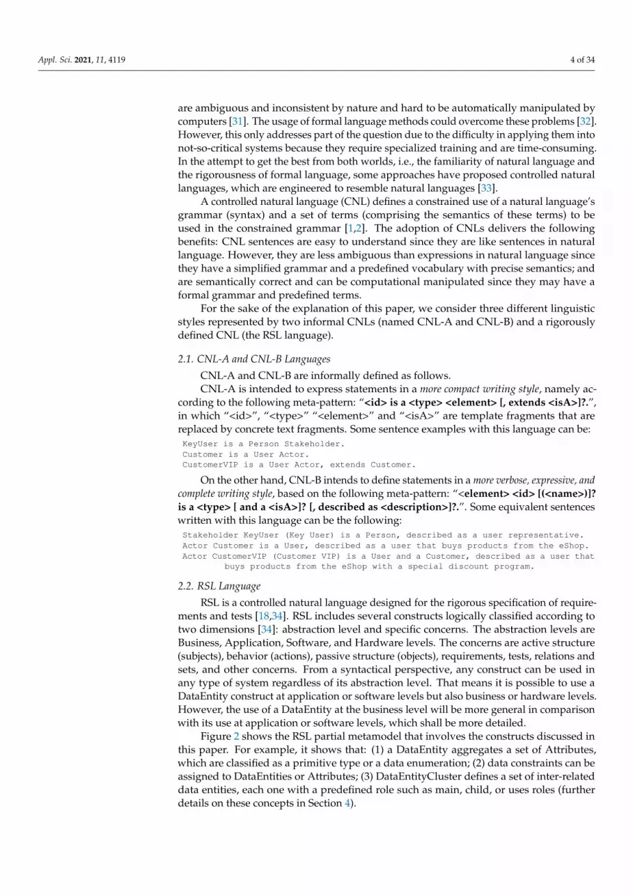
Figure 2 shows the RSL partial metamodel that involves the constructs discussed inthis paper. For example, it shows that: (1) a DataEntity aggregates a set of Attributes,which are classified as a primitive type or a data enumeration; (2) data constraints can beassigned to DataEntities or Attributes; (3) DataEntityCluster defines a set of inter-relateddata entities, each one with a predefined role such as main, child, or uses roles (furtherdetails on these concepts in Section 4).
Appl. Sci. 2021, 11, 4119 5 of 34
Appl. Sci. 2021, 11, x FOR PEER REVIEW 5 of 34
However, the use of a DataEntity at the business level will be more general in comparison with its use at application or software levels, which shall be more detailed.
Figure 2 shows the RSL partial metamodel that involves the constructs discussed in this paper. For example, it shows that: (1) a DataEntity aggregates a set of Attributes, which are classified as a primitive type or a data enumeration; (2) data constraints can be assigned to DataEntities or Attributes; (3) DataEntityCluster defines a set of inter-related data entities, each one with a predefined role such as main, child, or uses roles (further details on these concepts in Section 4).
Figure 2. RSL partial metamodel with data entities related constructs (UML notation).
The examples illustrated above can be represented with RSL as: Stakeholder KeyUser “Key User”: Person [description “a user representative”] Actor Customer: User [description “a user that buys products from the eShop”] Actor CustomerVIP “Customer VIP”: User [isA Customer description “a user that
buys products from the eShop with a special discount program”]
3. Linguistic Patterns and Linguistic Styles As discussed originally by Silva [18], a linguistic pattern is a set of rules that defines
the elements and the vocabulary that will be used in the sentences of these requirements technical documents. An element rule consists in a set of element attributes (e.g., <id>, <name> or <type>) defined by the following properties: name, type, and multiplicity. On the other hand, a vocabulary rule defines a set of literal terms (e.g., ‘‘User”, ‘ExternalSys-tem”) used to categorize some element attributes and to restrict the use of a limited num-ber of terms. For example, the linguistic pattern Actor is defined by the following set of rules (i.e., the Actor element rule and the ActorType vocabulary rule): Actor:: <id:ID> <name:String> <type:ActorType> <stakeholder:Stakeholder>? <isA:Actor>? <description:String>? enum ActorType:: User | ExternalSystem
The Actor element rule defines its element attributes (e.g., <id>, <name>, <type>, <isA>, <stakeholder>, <description>) and for each attribute the respective name (e.g., name, type, isA), type (e.g., ID, String, ActorType, Stakeholder) and multiplicity (e.g., ‘?’) properties. The multiplicity of an attribute is not represented by default (and in this case means “1”, a mandatory attribute), or can be represented by the following characters ‘?’, ‘+’, and ‘*’ meaning, respectively, 0..1 (optional), 1..* (one or many), and 0..* (zero or many).
Figure 2. RSL partial metamodel with data entities related constructs (UML notation).
The examples illustrated above can be represented with RSL as:Stakeholder KeyUser “Key User”: Person [description “a user representative”]Actor Customer: User [description “a user that buys products from the eShop”]Actor CustomerVIP “Customer VIP”: User [isA Customer description “a user that
buys products from the eShop with a special discount program”]
3. Linguistic Patterns and Linguistic Styles
As discussed originally by Silva [18], a linguistic pattern is a set of rules that defines theelements and the vocabulary that will be used in the sentences of these requirements tech-nical documents. An element rule consists in a set of element attributes (e.g., <id>, <name>or <type>) defined by the following properties: name, type, and multiplicity. On the otherhand, a vocabulary rule defines a set of literal terms (e.g., “User”, ‘ExternalSystem”) usedto categorize some element attributes and to restrict the use of a limited number of terms.For example, the linguistic pattern Actor is defined by the following set of rules (i.e., theActor element rule and the ActorType vocabulary rule):Actor::
<id:ID> <name:String> <type:ActorType><stakeholder:Stakeholder>? <isA:Actor>? <description:String>?
enum ActorType::User | ExternalSystem
The Actor element rule defines its element attributes (e.g., <id>, <name>, <type>,<isA>, <stakeholder>, <description>) and for each attribute the respective name (e.g.,name, type, isA), type (e.g., ID, String, ActorType, Stakeholder) and multiplicity (e.g., ‘?’)properties. The multiplicity of an attribute is not represented by default (and in this casemeans “1”, a mandatory attribute), or can be represented by the following characters ‘?’,‘+’, and ‘*’ meaning, respectively, 0..1 (optional), 1..* (one or many), and 0..* (zero or many).The type of an attribute can be a type (e.g., ID, String, Boolean); an element type (e.g., theActor of the isA attribute); or a vocabulary type (e.g., the ActorType of the type of attribute).
The ActorType vocabulary rule is prefixed with the “enum” tag and defines the valuesof its parts, namely the literals ‘User’, and ‘ExternalSystem’.
As shown in this simple example, a linguistic pattern defines two key aspects: a set ofelement attributes with respective name, type, and multiplicity; and a vocabulary, with alimited number of terms.
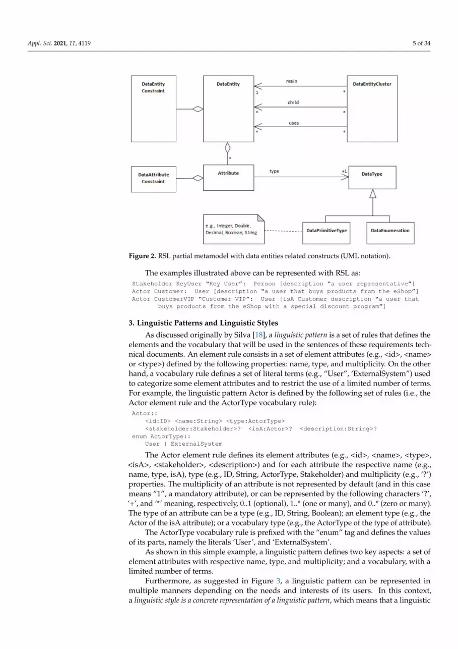
Furthermore, as suggested in Figure 3, a linguistic pattern can be represented inmultiple manners depending on the needs and interests of its users. In this context,a linguistic style is a concrete representation of a linguistic pattern, which means that a linguistic
Appl. Sci. 2021, 11, 4119 6 of 34
style is a specific template to which attributes of the linguistic pattern can be substituted.Thus, a linguistic pattern can be represented by multiple linguistic styles, such as RSL, CNL-A,CNL-B, and others.
Appl. Sci. 2021, 11, x FOR PEER REVIEW 6 of 34
The type of an attribute can be a type (e.g., ID, String, Boolean); an element type (e.g., the Actor of the isA attribute); or a vocabulary type (e.g., the ActorType of the type of attrib-ute).
The ActorType vocabulary rule is prefixed with the “enum” tag and defines the val-ues of its parts, namely the literals ‘User’, and ‘ExternalSystem’.
As shown in this simple example, a linguistic pattern defines two key aspects: a set of element attributes with respective name, type, and multiplicity; and a vocabulary, with a limited number of terms.
Furthermore, as suggested in Figure 3, a linguistic pattern can be represented in mul-tiple manners depending on the needs and interests of its users. In this context, a linguistic style is a concrete representation of a linguistic pattern, which means that a linguistic style is a specific template to which attributes of the linguistic pattern can be substituted. Thus, a linguistic pattern can be represented by multiple linguistic styles, such as RSL, CNL-A, CNL-B, and others.
Figure 3. Relation between linguistic pattern and linguistic style (UML notation).
A linguistic style is an ordered set of two types of text fragments: literal text frag-ments (e.g., ‘actor’, ‘[‘, ‘]’, ‘, described as‘); and other template text fragments that are rep-resented by the pattern “<element_name.attribute_name>”, i.e., the element name fol-lowed by its attribute name, delimited between ‘<’ and ‘>’ (e.g., <actor.type>). For brevity, it is possible to omit the reference to the “element_name.”. The multiplicity constraints are represented by the same characters referred to above (i.e., ‘?’, ‘+’ and ‘*’).
Also, the syntactical rules that define RSL constructs are compliant with the follow-ing general linguistic style, as a set of formal rules defined by an Extended BNF grammar. This grammar is supported by the Xtext framework [35], which provides a ready-to-use integrated authoring tool, built on top of the Eclipse IDE. ‘Element’ id=ID (name=STRING)? ‘:’ type=ElementType (‘[‘ ‘isA’ super=[Element])? (‘description’ description=STRING)? [etc.] ‘]’)?
We can even use different formats to define the linguistic styles. For example, using a verbose representation (i.e., using complete names of the attributes), we might have: Actor <actor.id> [<actor.name>]? is a <actor.type> [, extends <actor.isA>]? [,
associated to the stakeholder <actor.stakeholder>]? [, described as <ac-tor.description>]?.
Or using a more compact representation (i.e., using unqualified names of the attrib-utes) we may have the equivalent representation. For the sake of simplicity, this would be the adopted format to represent the linguistic styles CNL-A and CNL-B throughout this paper: Actor <id> [<name>]? is a <type> [, extends <isA>]? [, associated to the stake-
holder <stakeholder>]? [, described as <description>]?.
While for the definition of the RSL, we use the following type of representation:
Figure 3. Relation between linguistic pattern and linguistic style (UML notation).
A linguistic style is an ordered set of two types of text fragments: literal text fragments(e.g., ‘actor’, ‘[‘, ‘]’, ‘, described as‘); and other template text fragments that are representedby the pattern “<element_name.attribute_name>”, i.e., the element name followed by itsattribute name, delimited between ‘<’ and ‘>’ (e.g., <actor.type>). For brevity, it is possibleto omit the reference to the “element_name.”. The multiplicity constraints are representedby the same characters referred to above (i.e., ‘?’, ‘+’ and ‘*’).
Also, the syntactical rules that define RSL constructs are compliant with the followinggeneral linguistic style, as a set of formal rules defined by an Extended BNF grammar.This grammar is supported by the Xtext framework [35], which provides a ready-to-useintegrated authoring tool, built on top of the Eclipse IDE.‘Element’ id=ID (name=STRING)? ‘:’ type=ElementType
(‘[‘ ‘isA’ super=[Element])? (‘description’ description=STRING)? [etc.] ‘]’)?
We can even use different formats to define the linguistic styles. For example, using averbose representation (i.e., using complete names of the attributes), we might have:Actor <actor.id> [<actor.name>]? is a <actor.type> [, extends <actor.isA>]? [,
associated to the stakeholder <actor.stakeholder>]? [, described as<actor.description>]?.
Or using a more compact representation (i.e., using unqualified names of the attributes)we may have the equivalent representation. For the sake of simplicity, this would be theadopted format to represent the linguistic styles CNL-A and CNL-B throughout this paper:Actor <id> [<name>]? is a <type> [, extends <isA>]? [, associated to the
stakeholder <stakeholder>]? [, described as <description>]?.
While for the definition of the RSL, we use the following type of representation:‘Actor’ name=ID (nameAlias=STRING)? ‘:’ type=ActorType (‘[‘
(‘isA’ super=[Actor])?(‘stakeholder’ stakeholder= Stakeholder)(‘description’ description=STRING)? ‘]’)?
4. Data Entities’ Linguistic Patterns and Linguistic Styles
Data entities denote structural entities that exist in information systems, commonlyassociated with data concepts captured and identified from requirements elicitation anddomain analysis processes. (These entities can later be represented by data structures, liketables or collections of some databases, but that is out of the scope of this paper.)
As illustrated in the mind map of Figure 4, this suggests the existence and relationshipof the following concepts: data entity, data attribute, data entity constraint, data attributeconstraint, cluster of data entities, data enumeration, and data primitive type. Often these

Appl. Sci. 2021, 11, 4119 7 of 34
concepts appear in many specifications but scattered throughout the text and inconsistentlywith different names or different writing styles, as briefly introduced above in Section 1and depicted in Figure 1. In this section, we argue that for all these concepts, there arepatterns that might have diverse but consistent representations.
Appl. Sci. 2021, 11, x FOR PEER REVIEW 7 of 34
‘Actor’ name=ID (nameAlias=STRING)? ‘:’ type=ActorType (‘[‘ (‘isA’ super=[Actor])? (‘stakeholder’ stakeholder= Stakeholder) (‘description’ description=STRING)? ‘]’)?
4. Data Entities’ Linguistic Patterns and Linguistic Styles Data entities denote structural entities that exist in information systems, commonly
associated with data concepts captured and identified from requirements elicitation and domain analysis processes. (These entities can later be represented by data structures, like tables or collections of some databases, but that is out of the scope of this paper.)
As illustrated in the mind map of Figure 4, this suggests the existence and relation-ship of the following concepts: data entity, data attribute, data entity constraint, data at-tribute constraint, cluster of data entities, data enumeration, and data primitive type. Of-ten these concepts appear in many specifications but scattered throughout the text and inconsistently with different names or different writing styles, as briefly introduced above in Section 1 and depicted in Figure 1. In this section, we argue that for all these concepts, there are patterns that might have diverse but consistent representations.
Figure 4. General view of the Data Entities’ linguistic patterns (Mind Map notation).
This paper uses a running example to support the explanation and discussion. This example refers to the requirements of a fictitious information system called “BillingSys-tem”, which is an invoice management system inspired and adapted from the example initially introduced by Silva [18]. Figure 5 depicts the main data entities and relationships of this example with a simplified UML class diagram: the BillingSystem must manage data entities like invoices with invoice lines, customers, users, products, etc. For the sake of simplicity, the examples showed in this section are only in CNL-A and CNL-B nota-tions. However, Appendix A shows a complete description of these specifications in CNL-A, CNL-B and RSL, as well an equivalent UML model.
Figure 5. Domain model of the running example (UML notation).
Figure 4. General view of the Data Entities’ linguistic patterns (Mind Map notation).
This paper uses a running example to support the explanation and discussion. Thisexample refers to the requirements of a fictitious information system called “BillingSystem”,which is an invoice management system inspired and adapted from the example initiallyintroduced by Silva [18]. Figure 5 depicts the main data entities and relationships of thisexample with a simplified UML class diagram: the BillingSystem must manage data entitieslike invoices with invoice lines, customers, users, products, etc. For the sake of simplicity,the examples showed in this section are only in CNL-A and CNL-B notations. However,Appendix A shows a complete description of these specifications in CNL-A, CNL-B andRSL, as well an equivalent UML model.
Appl. Sci. 2021, 11, x FOR PEER REVIEW 7 of 34
‘Actor’ name=ID (nameAlias=STRING)? ‘:’ type=ActorType (‘[‘ (‘isA’ super=[Actor])? (‘stakeholder’ stakeholder= Stakeholder) (‘description’ description=STRING)? ‘]’)?
4. Data Entities’ Linguistic Patterns and Linguistic Styles Data entities denote structural entities that exist in information systems, commonly
associated with data concepts captured and identified from requirements elicitation and domain analysis processes. (These entities can later be represented by data structures, like tables or collections of some databases, but that is out of the scope of this paper.)
As illustrated in the mind map of Figure 4, this suggests the existence and relation-ship of the following concepts: data entity, data attribute, data entity constraint, data at-tribute constraint, cluster of data entities, data enumeration, and data primitive type. Of-ten these concepts appear in many specifications but scattered throughout the text and inconsistently with different names or different writing styles, as briefly introduced above in Section 1 and depicted in Figure 1. In this section, we argue that for all these concepts, there are patterns that might have diverse but consistent representations.
Figure 4. General view of the Data Entities’ linguistic patterns (Mind Map notation).
This paper uses a running example to support the explanation and discussion. This example refers to the requirements of a fictitious information system called “BillingSys-tem”, which is an invoice management system inspired and adapted from the example initially introduced by Silva [18]. Figure 5 depicts the main data entities and relationships of this example with a simplified UML class diagram: the BillingSystem must manage data entities like invoices with invoice lines, customers, users, products, etc. For the sake of simplicity, the examples showed in this section are only in CNL-A and CNL-B nota-tions. However, Appendix A shows a complete description of these specifications in CNL-A, CNL-B and RSL, as well an equivalent UML model.
Figure 5. Domain model of the running example (UML notation).
Figure 5. Domain model of the running example (UML notation).
4.1. Data Entity
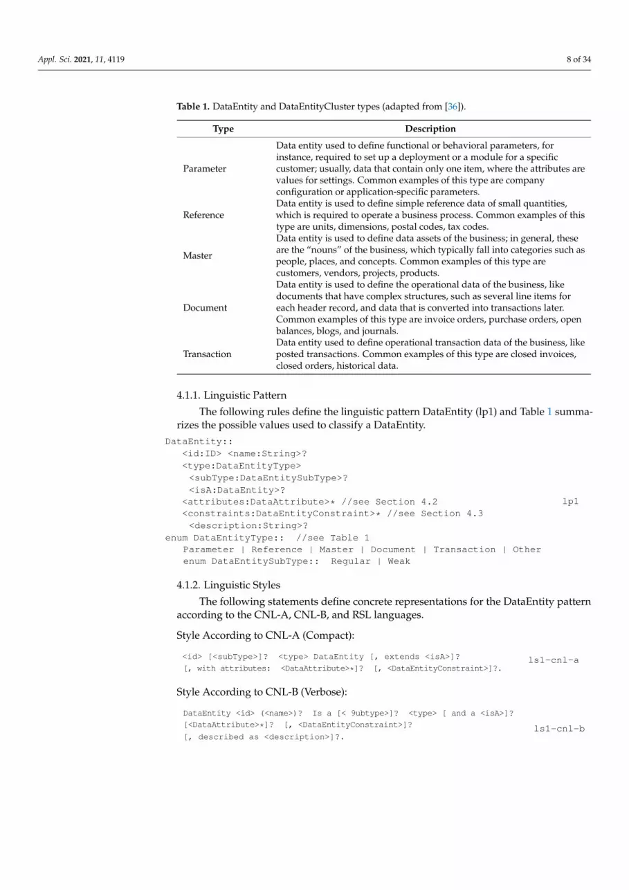
The construct DataEntity denotes an individual structural entity that might include thespecification of attributes and data constraints. A type and an optional subtype categorizea DataEntity. DataEntity type values can be the following, as proposed for instanceby Microsoft [36]: “Parameter”, “Reference”, “Master”, “Document” and “Transaction”;based on their purposes and the type of data that they serve (see Table 1 for furtherinformation). Moreover, DataEntity subtype values can be defined as “Regular” and“Weak” (as suggested originally by Chen [19]), meaning, respectively, that the data entityhas its relevance and identification (e.g., the Invoice entity) or that its existence depends onanother entity (e.g., the InvoiceLine entity that depends on the Invoice entity). A DataEntitycan also include a set of attributes (which denotes a particular structural property) as wellas a set of data constraints.
Appl. Sci. 2021, 11, 4119 8 of 34
Table 1. DataEntity and DataEntityCluster types (adapted from [36]).
Type Description
Parameter
Data entity used to define functional or behavioral parameters, forinstance, required to set up a deployment or a module for a specificcustomer; usually, data that contain only one item, where the attributes arevalues for settings. Common examples of this type are companyconfiguration or application-specific parameters.
ReferenceData entity is used to define simple reference data of small quantities,which is required to operate a business process. Common examples of thistype are units, dimensions, postal codes, tax codes.
Master
Data entity is used to define data assets of the business; in general, theseare the “nouns” of the business, which typically fall into categories such aspeople, places, and concepts. Common examples of this type arecustomers, vendors, projects, products.
Document
Data entity is used to define the operational data of the business, likedocuments that have complex structures, such as several line items foreach header record, and data that is converted into transactions later.Common examples of this type are invoice orders, purchase orders, openbalances, blogs, and journals.
TransactionData entity used to define operational transaction data of the business, likeposted transactions. Common examples of this type are closed invoices,closed orders, historical data.
4.1.1. Linguistic Pattern
The following rules define the linguistic pattern DataEntity (lp1) and Table 1 summa-rizes the possible values used to classify a DataEntity.
DataEntity::<id:ID> <name:String>?<type:DataEntityType><subType:DataEntitySubType>?<isA:DataEntity>?
<attributes:DataAttribute>* //see Section 4.2<constraints:DataEntityConstraint>* //see Section 4.3<description:String>?
enum DataEntityType:: //see Table 1Parameter | Reference | Master | Document | Transaction | Otherenum DataEntitySubType:: Regular | Weak
lp1
4.1.2. Linguistic Styles
The following statements define concrete representations for the DataEntity patternaccording to the CNL-A, CNL-B, and RSL languages.
Style According to CNL-A (Compact):
<id> [<subType>]? <type> DataEntity [, extends <isA>]?
[, with attributes: <DataAttribute>*]? [, <DataEntityConstraint>]?.ls1-cnl-a
Style According to CNL-B (Verbose):
DataEntity <id> (<name>)? Is a [< 9ubtype>]? <type> [ and a <isA>]?
[<DataAttribute>*]? [, <DataEntityConstraint>]?
[, described as <description>]?.ls1-cnl-b

Appl. Sci. 2021, 11, 4119 9 of 34
Style According to RSL:‘DataEntity’ name=ID (nameAlias=STRING)? ‘:’ type=DataEntityType(‘:’ subType=DataEntitySubType)? (‘[‘(‘isA’ super=[DataEntity | QualifiedName] )?(attributes+=DataAttribute)*(constraint=DataEntityConstraint)?(‘description’ description=STRING)? ‘]’)?
ls1-rsl
4.1.3. Examples
Considering the BillingSystem example (see Appendix A for a complete description)and following a text analysis, we identify and annotate the data entities with bold text,and hence capture concepts like Invoice, Customer, Customer VIP, Product, VAT.
A VAT consists of the following information: VAT code, rate, name, and value.The VAT rates consider the following values: standard, reduced, and special.[ . . . ] The system will maintain the following information for products: name,price, VAT rate, VAT value, and size category; a size category consists of oneof the following sizes: Small, Regular, Large, ExtraLarge. [ . . . ] The systemwill maintain the following information for customers: name, fiscal id,image, bank information, and additional information such as address andpersonal contacts. A customer can also be defined as a customer VIP, and inthis situation, there is a discount tax that can change over time. The operatorshall create invoices (with respective details defined as invoice lines).An invoice will have the following information [ . . . ].
Furthermore, we classify each of these data entities according to some taxonomy(e.g., such as that proposed and referred to in Table 1). For example, with the knowledgeobtaining from the domain analysis, we can classify the Invoice as a Document entity, andthe Customer as a Master entity, etc. From this analysis and considering the linguistic stylesdefined above, the data entities captured from the text can be represented as follows:
With the CNL-A Style (ls1-cnl-a):
e_VAT Reference DataEntity.e_Product Master DataEntity.e_Customer Master DataEntity.e_CustomerVIP Master DataEntity, extends e_Customer.e_Invoice Regular Document DataEntity.e_InvoiceLine Weak Document DataEntity.
With the CNL-B Style (ls1-cnl-b):
DataEntity e_VAT (VAT Category) is a Reference, described as [ . . . ]DataEntity e_Product (Product) is a Master, described as [ . . . ]DataEntity e_Customer (Customer) is a Master, described as [ . . . ]DataEntity e_CustomerVIP (CustomerVIP) is a Master and a e_Customer, described
as [ . . . ]DataEntity e_Invoice (Invoice) is a Regular Document, described as [ . . . ]DataEntity e_InvoiceLine (InvoiceLine) is a Weak Document, described as [ . . . ]
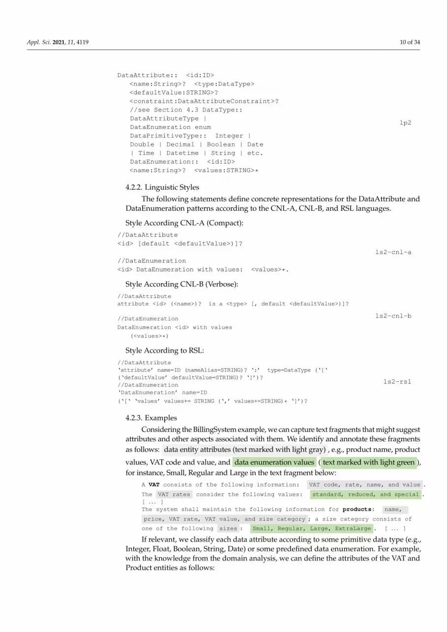
4.2. Data Attribute, DataPrimitiveType and DataEnumeration4.2.1. Linguistic Pattern
A DataAttribute denotes a particular structural property of a data entity. A dataattribute has the following properties: identifier (id), name, type, an optional default value(i.e., the value assigned by default), and some predefined constraints (DataAttributeCon-straint), such as NotNull, Unique, Derived, ReadOnly, Encrypted properties, multiplicity,or even other customized constraints.
A DataEnumeration denotes a customized data type with a predefined set of string values.A DataType (i.e., an attribute type) might be a primitive type (DataPrimitiveType, e.g., In-
teger, Double, String, Date, DateTime) or a customized data enumeration (DataEnumeration).The following rules define the linguistic patterns DataAttribute, DataType, and
DataEnumeration (lp2).
Appl. Sci. 2021, 11, 4119 10 of 34
DataAttribute:: <id:ID><name:String>? <type:DataType><defaultValue:STRING>?<constraint:DataAttributeConstraint>?//see Section 4.3 DataType::DataAttributeType |DataEnumeration enumDataPrimitiveType:: Integer |Double | Decimal | Boolean | Date| Time | Datetime | String | etc.DataEnumeration:: <id:ID><name:String>? <values:STRING>*
lp2
4.2.2. Linguistic Styles
The following statements define concrete representations for the DataAttribute andDataEnumeration patterns according to the CNL-A, CNL-B, and RSL languages.
Style According CNL-A (Compact)://DataAttribute<id> [default <defaultValue>)]?
//DataEnumeration<id> DataEnumeration with values: <values>*.
ls2-cnl-a
Style According CNL-B (Verbose)://DataAttributeattribute <id> (<name>)? is a <type> [, default <defaultValue>)]?
//DataEnumeration
DataEnumeration <id> with values
(<values>*)
ls2-cnl-b
Style According to RSL://DataAttribute‘attribute’ name=ID (nameAlias=STRING)? ‘:’ type=DataType (‘[‘(‘defaultValue’ defaultValue=STRING)? ‘]’)?//DataEnumeration‘DataEnumeration’ name=ID
(‘[‘ ‘values’ values+= STRING (‘,’ values+=STRING)* ‘]’)?
ls2-rsl
4.2.3. Examples
Considering the BillingSystem example, we can capture text fragments that might suggestattributes and other aspects associated with them. We identify and annotate these fragmentsas follows: data entity attributes (text marked with light gray) , e.g., product name, product
values, VAT code and value, and data enumeration values ( text marked with light green ),for instance, Small, Regular and Large in the text fragment below:
A VAT consists of the following information: VAT code, rate, name, and value .
The VAT rates consider the following values: standard, reduced, and special .[ . . . ]The system shall maintain the following information for products: name,
price, VAT rate, VAT value, and size category ; a size category consists of
one of the following sizes : Small, Regular, Large, ExtraLarge . [ . . . ]
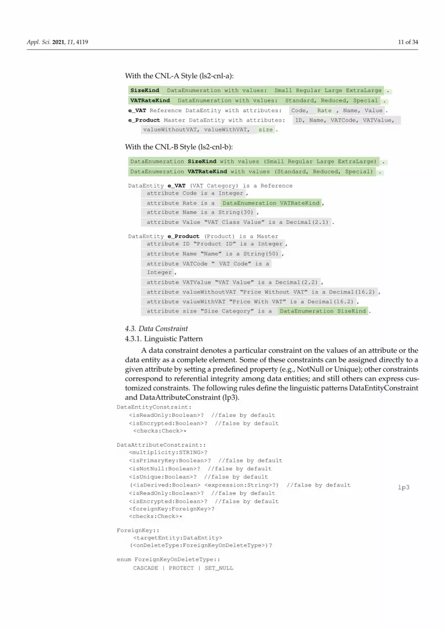
If relevant, we classify each data attribute according to some primitive data type (e.g.,Integer, Float, Boolean, String, Date) or some predefined data enumeration. For example,with the knowledge from the domain analysis, we can define the attributes of the VAT andProduct entities as follows:
Appl. Sci. 2021, 11, 4119 11 of 34
With the CNL-A Style (ls2-cnl-a):
SizeKind DataEnumeration with values: Small Regular Large ExtraLarge .
VATRateKind DataEnumeration with values: Standard, Reduced, Special .
e_VAT Reference DataEntity with attributes: Code, Rate , Name, Value .
e_Product Master DataEntity with attributes: ID, Name, VATCode, VATValue,
valueWithoutVAT, valueWithVAT, size .
With the CNL-B Style (ls2-cnl-b):
DataEnumeration SizeKind with values (Small Regular Large ExtraLarge) .
DataEnumeration VATRateKind with values (Standard, Reduced, Special) .
DataEntity e_VAT (VAT Category) is a Referenceattribute Code is a Integer ,
attribute Rate is a DataEnumeration VATRateKind ,
attribute Name is a String(30) ,
attribute Value “VAT Class Value” is a Decimal(2.1) .
DataEntity e_Product (Product) is a Masterattribute ID “Product ID” is a Integer ,
attribute Name “Name” is a String(50) ,
attribute VATCode “ VAT Code” is a
Integer ,
attribute VATValue “VAT Value” is a Decimal(2.2) ,
attribute valueWithoutVAT “Price Without VAT” is a Decimal(16.2) ,
attribute valueWithVAT “Price With VAT” is a Decimal(16.2) ,
attribute size “Size Category” is a DataEnumeration SizeKind .
4.3. Data Constraint4.3.1. Linguistic Pattern
A data constraint denotes a particular constraint on the values of an attribute or thedata entity as a complete element. Some of these constraints can be assigned directly to agiven attribute by setting a predefined property (e.g., NotNull or Unique); other constraintscorrespond to referential integrity among data entities; and still others can express cus-tomized constraints. The following rules define the linguistic patterns DataEntityConstraintand DataAttributeConstraint (lp3).
DataEntityConstraint:
<isReadOnly:Boolean>? //false by default
<isEncrypted:Boolean>? //false by default<checks:Check>*
DataAttributeConstraint::<multiplicity:STRING>?
<isPrimaryKey:Boolean>? //false by default
<isNotNull:Boolean>? //false by default
<isUnique:Boolean>? //false by default
(<isDerived:Boolean> <expression:String>?) //false by default
<isReadOnly:Boolean>? //false by default
<isEncrypted:Boolean>? //false by default<foreignKey:ForeignKey>?<checks:Check>*
ForeignKey::<targetEntity:DataEntity>
(<onDeleteType:ForeignKeyOnDeleteType>)?
enum ForeignKeyOnDeleteType::
CASCADE | PROTECT | SET_NULL
lp3
Appl. Sci. 2021, 11, 4119 12 of 34
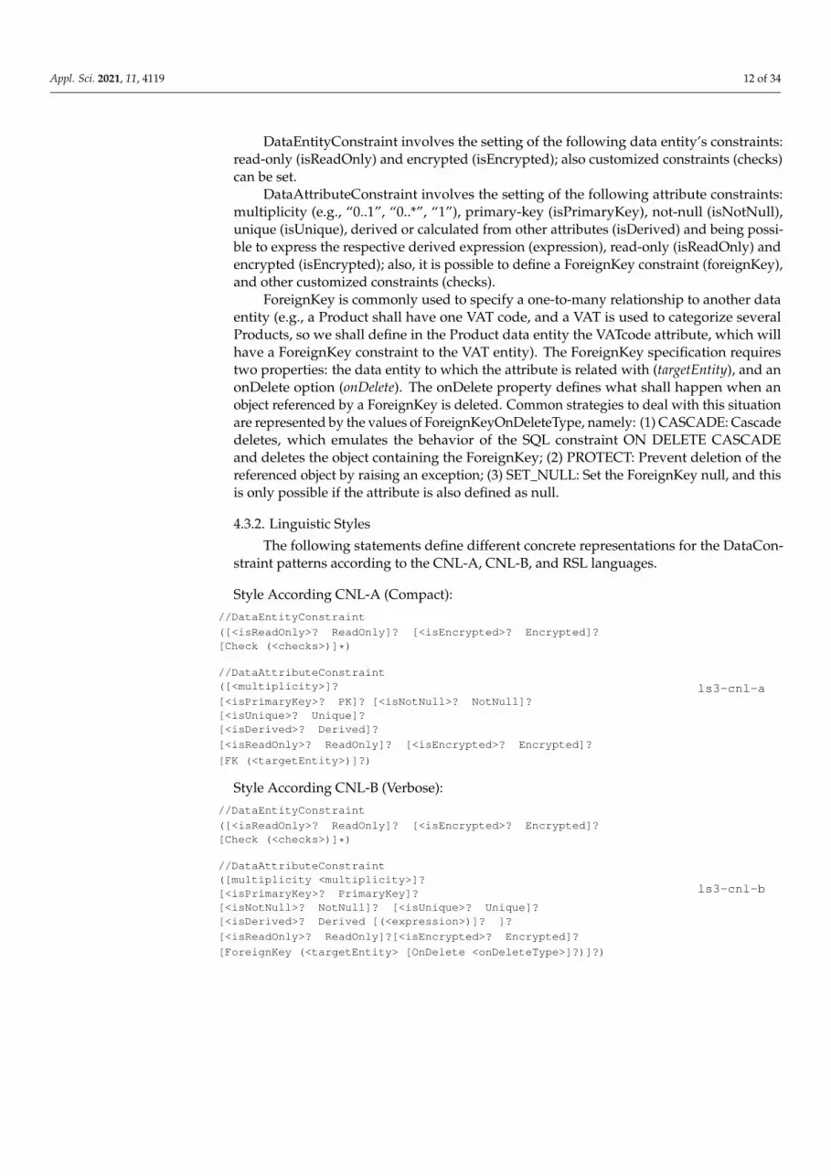
DataEntityConstraint involves the setting of the following data entity’s constraints:read-only (isReadOnly) and encrypted (isEncrypted); also customized constraints (checks)can be set.
DataAttributeConstraint involves the setting of the following attribute constraints:multiplicity (e.g., “0..1”, “0..*”, “1”), primary-key (isPrimaryKey), not-null (isNotNull),unique (isUnique), derived or calculated from other attributes (isDerived) and being possi-ble to express the respective derived expression (expression), read-only (isReadOnly) andencrypted (isEncrypted); also, it is possible to define a ForeignKey constraint (foreignKey),and other customized constraints (checks).
ForeignKey is commonly used to specify a one-to-many relationship to another dataentity (e.g., a Product shall have one VAT code, and a VAT is used to categorize severalProducts, so we shall define in the Product data entity the VATcode attribute, which willhave a ForeignKey constraint to the VAT entity). The ForeignKey specification requirestwo properties: the data entity to which the attribute is related with (targetEntity), and anonDelete option (onDelete). The onDelete property defines what shall happen when anobject referenced by a ForeignKey is deleted. Common strategies to deal with this situationare represented by the values of ForeignKeyOnDeleteType, namely: (1) CASCADE: Cascadedeletes, which emulates the behavior of the SQL constraint ON DELETE CASCADEand deletes the object containing the ForeignKey; (2) PROTECT: Prevent deletion of thereferenced object by raising an exception; (3) SET_NULL: Set the ForeignKey null, and thisis only possible if the attribute is also defined as null.
4.3.2. Linguistic Styles
The following statements define different concrete representations for the DataCon-straint patterns according to the CNL-A, CNL-B, and RSL languages.
Style According CNL-A (Compact)://DataEntityConstraint
([<isReadOnly>? ReadOnly]? [<isEncrypted>? Encrypted]?[Check (<checks>)]*)
//DataAttributeConstraint([<multiplicity>]?
[<isPrimaryKey>? PK]? [<isNotNull>? NotNull]?[<isUnique>? Unique]?[<isDerived>? Derived]?
[<isReadOnly>? ReadOnly]? [<isEncrypted>? Encrypted]?
[FK (<targetEntity>)]?)
ls3-cnl-a
Style According CNL-B (Verbose)://DataEntityConstraint
([<isReadOnly>? ReadOnly]? [<isEncrypted>? Encrypted]?[Check (<checks>)]*)
//DataAttributeConstraint([multiplicity <multiplicity>]?[<isPrimaryKey>? PrimaryKey]?[<isNotNull>? NotNull]? [<isUnique>? Unique]?[<isDerived>? Derived [(<expression>)]? ]?
[<isReadOnly>? ReadOnly]?[<isEncrypted>? Encrypted]?
[ForeignKey (<targetEntity> [OnDelete <onDeleteType>]?)]?)
ls3-cnl-b

Appl. Sci. 2021, 11, 4119 13 of 34
Style According RSL://DataEntityConstraint(isReadOnly=‘ReadOnly’)?(isEncrypted=‘Encrypted’)?
(checks+=‘Check’ ‘(‘ checkExpression=STRING ‘)’)*
//DataAttributeConstraint(‘multiplicity’ multiplicity=Multiplicity)?(isPrimaryKey=‘PrimaryKey’)?(isNotNull=‘NotNull’)?(isUnique=‘Unique’)?
(isDerived=‘Derived’) (‘(‘ ‘from’ expression=STRING) ‘)‘?)?(isReadOnly=‘ReadOnly’)?(isEncrypted=‘Encrypted’)?(foreignKey=ForeignKey)?
(checks+=‘Check’ ‘(‘ checkExpression=STRING ‘)’)*
//ForeignKey‘ForeignKey’ ‘(‘ entity=[DataEntity]
(‘onDelete’ onDelete=
ForeignKeyOnDeleteType )? ‘)’ ;
ls3-rsl
4.3.3. Examples
From the analysis of the BillingSystem example and the general understanding ofits domain, the VAT and Product data entities can be represented now in a complete way,by expressing their data constraints (text marked with light gray ), as follows with thelinguistic styles defined above.
With the Style of the CNL-A:
e_VAT is a Reference DataEntity: VATCode ( PK ), VATName ( NotNull ), VATValue
( NotNull ).
e_Product is a Master DataEntity: ID ( PK ), Name ( “1..2” ), VATCode ( NotNull FK
(e_VAT) ), VATValue ( NotNull Derived ), valueWithoutVAT ( NotNull ), valueWithVAT
( NotNull Derived ), size.
With the Style of the CNL-B:
DataEntity e_VAT (VAT Category) is a Referenceattribute VATCode “VAT Code” is a Integer ( PrimaryKey ),attribute Rate “Rate” is a DataEnumeration VATRateKind,attribute VATName “VAT Class Name” is a String(30) ( NotNull ),
attribute VATValue “VAT Class Value” is a Decimal(2.1)( NotNull ).
DataEntity e_Product (Product) is a Masterattribute ID “Product ID” is a Integer ( PrimaryKey )
attribute Name “Name” is a String(50) ( multiplicity “1..2” ),
attribute VATCode “VAT Code” is a Integer ( NotNull ForeignKey (e_VAT
onDelete PROTECT) ),
attribute VATValue “VAT Value” is a Decimal(2.2) ( NotNull Derived
(“e_VAT.VATValue”))
attribute valueWithoutVAT “Price Without VAT” is a Decimal(16.2) ( NotNull ),
attribute valueWithVAT “Price With VAT” is a Decimal(16.2) ( NotNull Derived
(“Self.valueWithoutVAT * (1 + Self.VATValue)”) ),
attribute size is a DataEnumeration SizeKind.
4.4. Cluster of Data Entities
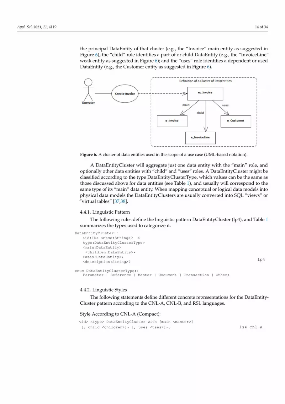
A DataEntityCluster denotes a group of data entities that have logical arrangementsamong themselves. A DataEntityCluster can be a construct particularly relevant whenassociated with use cases, as suggested in Figure 6. Each data entity that belongs to acluster has a specific role, namely: “main”, “child”, and “uses”. The “main” role identifies
Appl. Sci. 2021, 11, 4119 14 of 34
the principal DataEntity of that cluster (e.g., the “Invoice” main entity as suggested inFigure 6); the “child” role identifies a part-of or child DataEntity (e.g., the “InvoiceLine”weak entity as suggested in Figure 6); and the “uses” role identifies a dependent or usedDataEntity (e.g., the Customer entity as suggested in Figure 6).
Appl. Sci. 2021, 11, x FOR PEER REVIEW 13 of 34
DataEntity e_VAT (VAT Category) is a Reference attribute VATCode “VAT Code” is a Integer (PrimaryKey), attribute Rate “Rate” is a DataEnumeration VATRateKind, attribute VATName “VAT Class Name” is a String(30) (NotNull), attribute VATValue “VAT Class Value” is a Decimal(2.1)(NotNull).
DataEntity e_Product (Product) is a Master attribute ID “Product ID” is a Integer (PrimaryKey) attribute Name “Name” is a String(50) (multiplicity “1..2”), attribute VATCode “VAT Code” is a Integer (NotNull ForeignKey (e_VAT onDelete
PROTECT)), attribute VATValue “VAT Value” is a Decimal(2.2) (NotNull Derived (“e_VAT.
VATValue”)) attribute valueWithoutVAT “Price Without VAT” is a Decimal(16.2) (NotNull), attribute valueWithVAT “Price With VAT” is a Decimal(16.2) (NotNull Derived
(“Self.valueWithoutVAT * (1 + Self.VATValue)”)), attribute size is a DataEnumeration SizeKind.
4.4. Cluster of Data Entities A DataEntityCluster denotes a group of data entities that have logical arrangements
among themselves. A DataEntityCluster can be a construct particularly relevant when as-sociated with use cases, as suggested in Figure 6. Each data entity that belongs to a cluster has a specific role, namely: “main”, “child”, and “uses”. The “main” role identifies the principal DataEntity of that cluster (e.g., the “Invoice” main entity as suggested in Figure 6); the “child” role identifies a part-of or child DataEntity (e.g., the “InvoiceLine” weak entity as suggested in Figure 6); and the “uses” role identifies a dependent or used DataEntity (e.g., the Customer entity as suggested in Figure 6).
Figure 6. A cluster of data entities used in the scope of a use case (UML-based notation).
A DataEntityCluster will aggregate just one data entity with the “main” role, and optionally other data entities with “child” and “uses” roles. A DataEntityCluster might be classified according to the type DataEntityClusterType, which values can be the same as those discussed above for data entities (see Table 1), and usually will correspond to the same type of its “main” data entity. When mapping conceptual or logical data models into physical data models the DataEntityClusters are usually converted into SQL “views” or “virtual tables” [37,38].
4.4.1. Linguistic Pattern The following rules define the linguistic pattern DataEntityCluster (lp4), and Table 1
summarizes the types used to categorize it.
Figure 6. A cluster of data entities used in the scope of a use case (UML-based notation).
A DataEntityCluster will aggregate just one data entity with the “main” role, andoptionally other data entities with “child” and “uses” roles. A DataEntityCluster might beclassified according to the type DataEntityClusterType, which values can be the same asthose discussed above for data entities (see Table 1), and usually will correspond to thesame type of its “main” data entity. When mapping conceptual or logical data models intophysical data models the DataEntityClusters are usually converted into SQL “views” or“virtual tables” [37,38].
4.4.1. Linguistic Pattern
The following rules define the linguistic pattern DataEntityCluster (lp4), and Table 1summarizes the types used to categorize it.
DataEntityCluster::<id:ID> <name:String>? <type:DataEntityClusterType><main:DataEntity><children:DataEntity>*
<uses:DataEntity>*<description:String>?
enum DataEntityClusterType::Parameter | Reference | Master | Document | Transaction | Other;
lp4
4.4.2. Linguistic Styles
The following statements define different concrete representations for the DataEntity-Cluster pattern according to the CNL-A, CNL-B, and RSL languages.
Style According to CNL-A (Compact):<id> <type> DataEntityCluster with [main <master>]
[, child <children>]* [, uses <uses>]*. ls4-cnl-a
Appl. Sci. 2021, 11, 4119 15 of 34
Style According to CNL-B (Verbose):
DataEntityCluster <id> (<name>)? is a <type> with[<master> as the main entity][, <children> as child entity]* [, <uses > as uses entity]*[, <description>]?.
ls4-cnl-b
Style According to RSL:
‘DataEntityCluster’ name=ID (nameAlias=STRING)? ‘:’ type=DataEntityClusterType (‘[‘(main=MainDEntity)(children+=ChildDEntity)*(uses+=UseDEntity)*(‘description’ description=STRING)? ‘]’)?
ls4-rsl
4.4.3. Examples
From the analysis of the BillingSystem example and considering the linguistic stylesdefined above, the clusters of data entities can be represented as follows:
With the Style ls4-cnl-a:
ec_Product Master DataEntityCluster with main e_Product, uses e_VAT.ec_Invoice Document DataEntityCluster with main e_Invoice, child e_InvoiceLine,
uses e_Customer.
With the Style ls4-cnl-b:
DataEntityCluster ec_Product is a Master with e_Product as the main entity,e_VAT as the uses entity.
DataEntityCluster ec_Invoice is a Document with e_Invoice as the main entity,
e_InvoiceLine as child entity, e_Customer as the uses entity.
5. Related Work
The process of producing requirements specifications consists of creating descriptionsof the application domain as well as a prescription of what the system should do, andother organizational, legal, or technological constraints [39]. In general, these requirementsare specified in natural languages because of their higher expressiveness and ease ofuse. However, natural languages present drawbacks like ambiguity, inconsistency, andincompleteness [1,2,9,40], and so, their specifications are usually complemented by somesort of other requirements and models that use CNLs, formal or modeling languages. Theselanguages provide constructs (e.g., data entity, actor, use case, or requirement) that defineits abstract syntax and semantics, and address diverse concerns and abstraction levels.Also, these languages provide different notations or concrete syntaxes, such as textual,graphical, tabular, or form-based representations [28,41,42].
On the other hand, data modeling involves the definition of different data modelsor data schemas defined at different levels of abstraction [37,38]. In this respect, Ribeiroet al. [42] present an extensive discussion and give examples of data modeling and dataanalytics processes. They discuss data modeling at different abstraction levels (i.e., concep-tual, logical, and physical data models) considering not only operational but also decisionsupport and big data technologies [42].
Moreover, ontology engineering has proposed methods for building ontologies, whichare formal representations of a set of concepts within a domain and the relationships be-tween those concepts. For instance, as Tudorache discussed [43], ontology engineering hasbeen strengthened by the adoption of standards about ontologies, by the development orextension of ontology software tools, and the by wider recognition of the importance of stan-dardized vocabularies and formalized semantics. However, despite these advancements,ontology engineering is still a difficult process, and many challenges remain to be solved.
Appl. Sci. 2021, 11, 4119 16 of 34
For instance, semantic web languages, especially OWL, have a high learning curve [44],even for technical people with software engineering or database backgrounds [43].
Although this paper is focused on CNLs and their intrinsic linguistic patterns, we dis-cuss below other approaches with concrete languages and discuss their key characteristicsin what concerns the specification of data entities and data modeling.
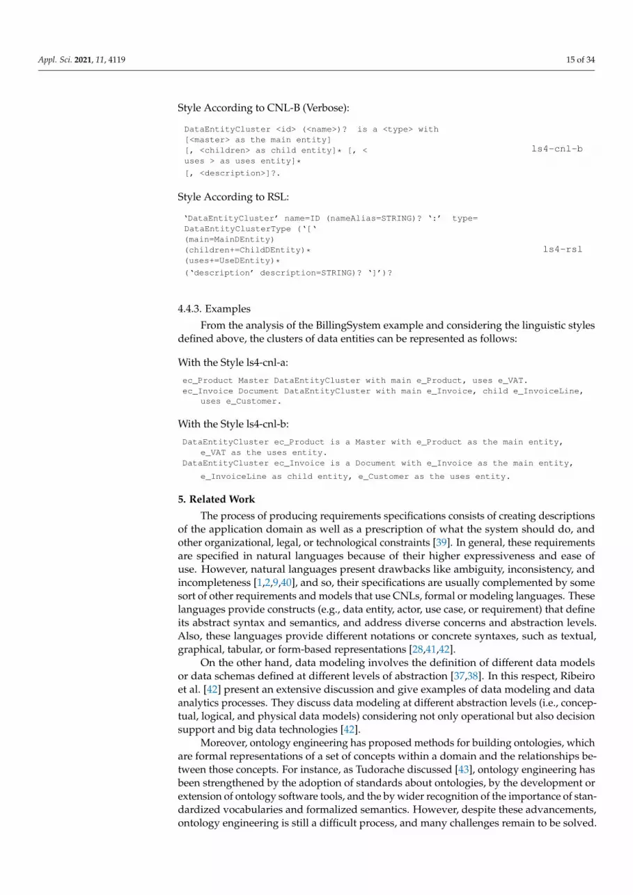
Tables 2 and 3 summarize the comparison of the languages analyzed below. Thatincludes the classification of each language grouped by the following language categories:natural language, formal language, controlled natural language, and modeling language.
Table 2 compares these languages based on the following aspects: (1) the languageapplication scope (e.g., general communication, software engineering, system engineering,or requirements engineering); (2) the language definition technique (e.g., grammar, meta-modeling, or implicitly); (3) the language concrete syntax (e.g., textual, graphical, tabular,or form-based); and (4) the language classification based on the PENS schema.
PENS is a CNL classification framework proposed by Kuhn [33], based on the fol-lowing dimensions: Precision, Expressiveness, Naturalness, and Simplicity; with eachdimension classified in a 1 to 5 scale of classes. These PENS dimensions have the followingmeaning: Precision captures the degree to which the meaning of a text in a certain languagecan be directly retrieved from its textual form, i.e., the sequence of language symbols.Expressiveness describes the range of propositions that a given language can express. Natu-ralness describes how close the language is to a natural language in terms of readabilityand understandability to speakers of the given language. Simplicity is a measure of howsimple or difficult is to comprehensively describe a given language, which will cover thedescription of its syntax and semantics; it is not a measure for the effort needed by a humanto learn the language, but rather it is closely related to the effort needed to fully implementthe syntax and semantics of a language by a computer program (because of that, the name“simplicity” can be misunderstood, and maybe “computability” could be a better namefor this dimension; nevertheless, we keep the original name as proposed by Kuhn withthis caveat).
Table 2. Comparison of languages used for data entity specification and data modeling: PENS analysis.
LanguageCategory Language Scope Definition
(Meta-Language) Concrete Syntax PENSClassification
NaturalLanguage English General
Communication [Implicit] Textual [Tabular] P1E5N5S1
FormalLanguage B Method Software Engineering Explicit (BNF Grammar) Textual P5E1N1S4
CNLACE Knowledge
Representation Explicit (Rules) Textual [Tabular] P4E3N4S3
RNL-ER Data Modeling Explicit (Rules) Textual P3E2N4S3
SilabREQ Software Engineering Explicit (BNF Grammar) Textual [Tabular] P4E2N2S4
ModelingLanguage
UML Software Engineering Explicit (MOF) Graphical P3E3N1S3
SysML Systems Engineering Explicit (UML) Graphical P3E3N1S3
RML RequirementsEngineering [Implicit] Graphical, Tabular,
Form P2E3N2S2
XIS* Software Engineering Explicit (UML) Graphical P4E2N1S3
CNLs showed in thepaper
CNL-A RequirementsEngineering [Implicit] Textual [Tabular] P3E3N4S3
CNL-B RequirementsEngineering [Implicit] Textual [Tabular] P3E4N4S3
RSL RequirementsEngineering Explicit (BNF Grammar) Textual [Tabular,
Graphical] P4E4N3S4
Appl. Sci. 2021, 11, 4119 17 of 34
Table 3. Comparison of languages used for data entity specification and data modeling: Concepts supported.
LanguageCategory Language
Data Entity DataEntity ClusterData
EnumerationConcept Type isA ConstraintData Attribute Concept Type Entity
RolesConcept Type Constraint
NaturalLanguage English NA NA NA NA NA NA NA NA NA NA NA
FormalLanguage
BMethod
AbstractMachine N N
Y: Asser-tion,
Invari-ant
Property N
Y: Asser-tion,
Invari-ant
NA NA NA N
CNLACE NA NA NA NA NA NA NA NA NA NA NA
RNL-ER Entity N N N Attribute Y Y: Multi-plicity N N N N
SilabREQ DataConcept N Y N Attribute Y N N N N N
ModelingLanguage
UML Class N YY: AnyCon-
straintAttribute Y
Y: Multi-plicity,
Derived,Any
N N N Y
SysML Class,Block N Y
Y: AnyCon-
straintAttribute Y
Y: Multi-plicity,
Derived,Any
N N N Y
RMLBusiness
DataObject
N N BusinessRule Field Y
Property,Business
RuleN N N N
XIS* Entity N Y N EntityAttribute Y Y: PK,
NullBusiness
Entity N Y Y
CNLsshowed inthe paper
CNL-A DataEntity Y Y Y Data
Attribute N Y AllData
EntityCluster
Y Y Y
CNL-B DataEntity Y Y Y Data
Attribute Y Y: AllData
EntityCluster
Y Y Y
RSL DataEntity Y Y Y Data
Attribute Y Y: AllData
EntityCluster
Y Y Y
For example, for Precision and Simplicity, English is on the bottom end of the scalein class 1, represented as P1 and S1. On the opposite end of the scale, a formal languagelike B is in classes 5 and 4, represented with P5 and S4. For expressiveness and naturalness,the roles are switched: English is at the top end (E5 and N5) and B formal language at thebottom (E1 and N1). As pointed out by Kuhn, in general, more is better for each of thePENS dimensions, however, this does not necessarily hold in practice. Indeed, a certainlevel in any of the dimensions is often good enough for a given application domain andgoing beyond that level will not bring additional benefit [33]. Apart from few languages(i.e., English, B, and ACE), which were previously discussed and evaluated by Kuhn,the PENS-based evaluation of the other languages was performed by us in a reflectiveapproach and, therefore, subject to some subjectivity and debate.
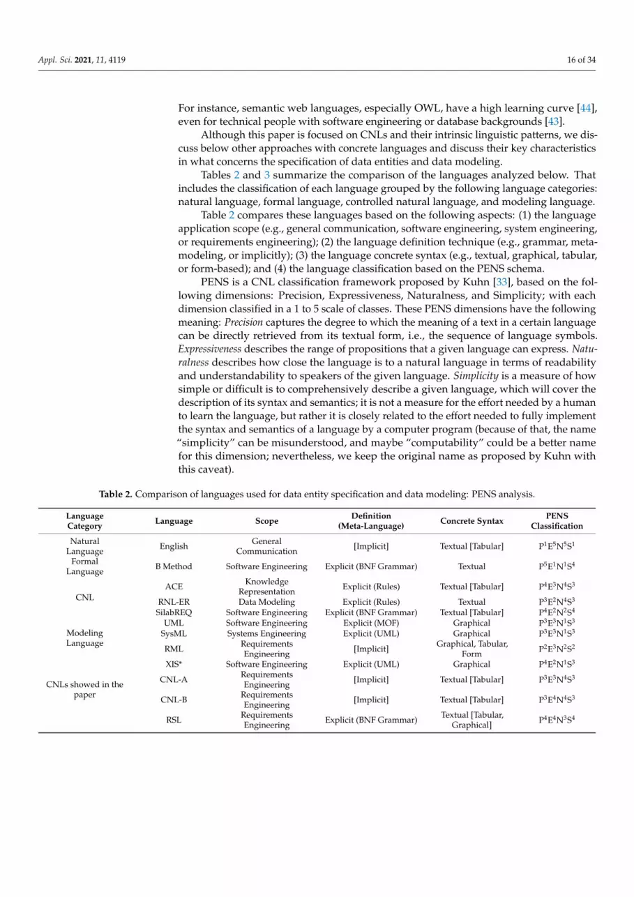
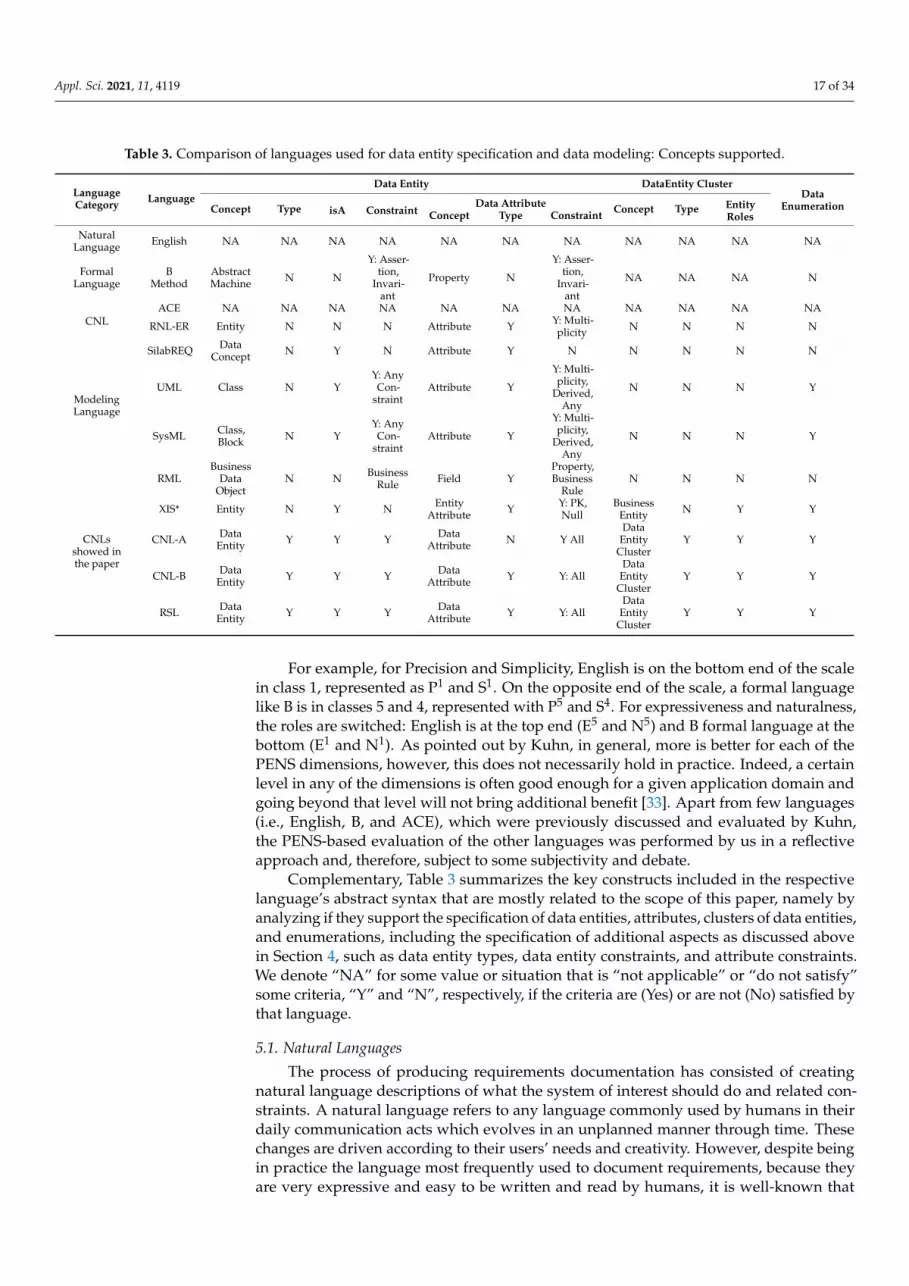
Complementary, Table 3 summarizes the key constructs included in the respectivelanguage’s abstract syntax that are mostly related to the scope of this paper, namely byanalyzing if they support the specification of data entities, attributes, clusters of data entities,and enumerations, including the specification of additional aspects as discussed abovein Section 4, such as data entity types, data entity constraints, and attribute constraints.We denote “NA” for some value or situation that is “not applicable” or “do not satisfy”some criteria, “Y” and “N”, respectively, if the criteria are (Yes) or are not (No) satisfied bythat language.
5.1. Natural Languages
The process of producing requirements documentation has consisted of creatingnatural language descriptions of what the system of interest should do and related con-straints. A natural language refers to any language commonly used by humans in theirdaily communication acts which evolves in an unplanned manner through time. Thesechanges are driven according to their users’ needs and creativity. However, despite beingin practice the language most frequently used to document requirements, because theyare very expressive and easy to be written and read by humans, it is well-known that

Appl. Sci. 2021, 11, 4119 18 of 34
these specifications are ambiguous and inconsistent by nature, and hard to be interpretedand checked automatically by computers [1,2]. In what concerns the documentation ofdata entities, natural language-based specifications tend to be inconsistent and incomplete:only define the names of data entities and their data attributes, but, for instance, miss theexplicit definition of the involved types, constraints, or even these names use to be writteninconsistently as discussed originally in Section 1 and illustrated in Figure 1. For thesereasons, a natural language, like English, is evaluated as P1E5N5S1 (see Table 2).
5.2. Formal Method Languages
Formal methods were expected to solve some of the drawbacks referred to as naturallanguage approaches, namely dealing with ambiguity and enabling the specification ofsoftware systems or just their components. Many formal methods (e.g., Z, VDM, B, Alloy)follow state-based formalisms [45], in which their languages provide constructs for definingmodular abstractions that have an internal state. These methods were also expected toexhibit an increased expressivity beyond algorithmic descriptions. For instance, the BMethod [32,46] is a popular representative of this class of approaches. It is a formalmethod that employs mathematical formalisms (such as set theory and logic) for iterativelydeveloping software through stepwise refinements, from its initial abstract specificationto its source code implementation. The B language is based on abstract machine notation,which is a specification language embedded with several high-level programming languagenotions. According to B specifications, the system of interest is represented as a set ofabstract machines. The notion of the abstract machine allows one to encapsulate boththe state and operations (on the state) of a system component and assign it a meaningfulname. This notation allows one to define an invariant based on the machine’s internalvariables, which must not be violated regardless of the abstract machine’s state. Besides, Bsupports the definition of constraints, which express requirements related to the applicationdomain; and assertions, which consist of a set of theorems that supports the processof discharging proof obligations and are essential to ensure that the resulting sourcecode can be proven to be consistent with the original specification. These invariants areequivalent to the (data entity and attributes) constraints discussed in this paper. However,the discussed constraints are not dependent on the behavior of the involved data entityand are more focused on the static or structural aspects. Despite the benefits arising fromthe usage of a sound theoretical foundation, formal methods present some limitations,namely their difficulty in properly using such formal languages, even for users with atechnical background but lacking the necessary mathematical foundation. In general, thecomplexity of these languages often impairs these approaches from being cost-effectivefor documenting and developing software systems other than mission-critical ones [47,48].Due to these reasons, B is evaluated as P5E1N1S4 (see Table 2).
5.3. Controlled Natural Languages
A controlled natural language (CNL) is a constructed language that is based on somenatural language, being more restrictive concerning lexicon, syntax, and semantics whilepreserving most of its natural properties [33]. CNL approaches have emerged in differentapplication domains and various disciplines such as computer science, philosophy, linguis-tics, and engineering. CNLs have been designed for better supporting technical writingor knowledge engineering. CNLs have been applied to improve communication amonghumans, to improve translation, or to provide natural and intuitive representations forformal notations. CNLs can be classified into two general categories: human-oriented andmachine-oriented CNLs. Human-oriented CNLs intend to improve the readability andcomprehensibility of technical documentation and to simplify and standardize human-human communication for specific purposes. On the other hand, machine oriented CNLsintend to improve the translatability of technical documents and the acquisition, repre-sentation, and processing of knowledge. Since the structure of CNLs is usually simplerthan the structure of natural language, CNLs are easier for a computer to process and more
Appl. Sci. 2021, 11, 4119 19 of 34
natural for humans to understand. An ideal CNL should also be effortless to write andexpressive enough to describe the problem at hand.
Schwitter surveys machine oriented CNLs that can be used for knowledge representa-tion and can serve as high-level interface languages to knowledge systems, namely [49]:Attempto Controlled English (ACE), Processable English (PENG), and Computer Process-able Language (CPL). Also, based on the PENS classification scheme, Kuhn surveys anextensive list of 100 English-based CNLs, including, for example, Basic English, CaterpillarFundamental English, SBVR Structured English, ACE, and Gherkin.
Among these CNLs, we highlight ACE as a relevant representative of this categoryof languages. ACE is a precisely defined subset of English that can automatically andunambiguously be translated into first-order logic [31]. ACE may appear to be completelynatural but is a formal language; concretely, it is a first-order logic language with Englishsyntax. ACE was first proposed as a language for software specifications, but later, its focusshifted towards knowledge representation and the semantic web. The essential features ofACE include complex noun phrases, plurals, anaphoric references, subordinated clauses,modality, and questions [31]. So, and contrary to this paper, which is focused on thedefinition of specific data entity elements that exist in requirements specifications, ACE is amore general-purpose language dedicated to knowledge representation that, of course, canrepresent all the discussed concepts, likewise a natural language. As showed in Table 2,ACE was originally classified by Kuhn as P4E3N4S3 [33].
RNL-ER [50] is a CNL for specifying entity-relationship models that not only solvethe verbalization problem for these models but also provides the benefits of automaticverification and validation, and semantic round-tripping which makes the communicationprocess transparent between the domain experts and the knowledge engineers. However,the RNL-ER language is particularly aligned with ER models and hence simpler in compar-ison with the linguistic patterns and styles discussed in this paper, e.g., it does not allow acomplete classification of data entities or data attributes or does not provide concepts likedata enumeration, more complete constraints, or data entity clusters. For these reasons,RNL-ER is classified as P3E2N4S3.
SilabREQ [51] is another CNL for use case specification that allows describing userand system actions in a precise way. SilabREQ enables automated analysis and processingof software requirements and to achieve the generation of different parts of informationsystems by the adoption of model-driven techniques. SilabREQ is formally defined bya BNF grammar that includes constructs like actors, use cases, data concepts, and statemachines. Contrary to other languages, SilabREQ proposes constructs to textually specifythe details of use cases, including scenarios and use case actions. As shown in Table 3,SilabREQ also allows the specification of data entities with its construct “Concept” but onlyin a simple way. For instance, it does not support concepts like a cluster of data entities,data enumeration, data constraints. Due to that SilabREQ is classified as P4E2N2S4.
5.4. Modeling Languages
Requirements specifications have been often documented according to a blendedapproach, i.e., by using natural language (or CNL) textual sentences complemented withgraphical models. These models are represented with general-purpose modeling languages,such as UML [21] or SysML [52], or with more specific modeling languages, such asRML [53] or XIS* [54–56]. Although these models can be more precise than plain textualspecifications, they still leave room for ambiguity and inconsistency; thus, they are usuallyconsidered as being semi-formal.
UML (Unified Modeling Language) [21] is the general-purpose modeling languagepromoted by OMG and considered by many as the de facto standard for modeling anddocumenting object-oriented software systems. UML is defined explicitly by the MOF(OMG Meta Object Facility) and provides many types of diagrams, such as class, object,sequence, use cases, state machine, component diagrams, etc., with several of them appliedat different abstraction levels. Considering its application to the specifications of require-
Appl. Sci. 2021, 11, 4119 20 of 34
ments, UML provides relevant constructs such as actors, use cases, classes/objects, andstate machines, which are commonly used as complementary representations.
SysML (Systems Modeling Language) [52] is another general-purpose modeling lan-guage mainly targeted for systems engineering. It supports the specification of an extensiverange of systems and systems-of-systems, involved not only software but also hardwareand other physical elements. SysML is defined as an extension of UML, using the UMLprofile mechanism, and mainly introducing new diagram types such as block definition,internal block, and requirements diagrams. On the other hand, SysML requirements dia-grams allow to illustrate requirements graphically (i.e., represented as a particular box witha name, and a stereotype) and their relationships, which are divided into two categories:relationships between requirements (e.g., containment, derive, and copy) and relationshipsbetween requirements and other model elements (e.g., satisfy, verify, refine, and trace).Although SysML includes this new requirement diagram, it suffers from the same draw-backs referred above for UML, namely in what concerns the multiple interpretations oftheir expressive but semi-formal models.
In what concerns the data entity constructs, UML and SysML allow a flexible definitionof entities, attributes, data enumerations, and even some simple and predefined constraints.However, foreign keys and more complex constraints are not easily defined graphically,sometimes are expressed as complementary annotations; still, the categorization of dataentities is not very common, though we still may use stereotypes for that purpose. Onthe other hand, the models produced with these languages are not natural and easy tounderstand by non-technical users, namely in comparison with CNL-based approaches.For these reasons, both UML and SysML are classified as P3E3N1S3 (see Table 2).
RML (Requirements Modeling Language) [53] is one of the largest RE-specific lan-guage that gathers many constructs and types of models, some of them found in popularmodeling languages such as UML or SysML, e.g., business data diagram or state diagram,or in earlier languages like Structured Analysis, e.g., data dictionary, system flow, statediagram. On the contrary to these languages, RML specifications are not just a graphicallanguage but provides also other representations such as tabular (e.g., data dictionary, rolesand permissions matrix, state table), and form-based (e.g., use cases). RML models areclassified into the following categories: objectives, people, systems, and data. The mostrelated to this paper are the business data diagram (BDD) and the data dictionary (DD).BDDs look very similar to ER diagrams and show business data objects and respectiverelationships from a business stakeholder’s perspective. Complementary, DDs define thefields that make up the business data objects by presenting in a tabular format the list ofthe respective attributes (fields), with the detail of their properties, such as id, name, datatype, valid values, and data attribute constraints. However, RML is defined implicitly,and consequently, its models/specifications are simple and intuitive but less rigorous andprecise in comparison with UML, SysML, or RSL (which are defined by metamodels orgrammars). Also, RML does not consider the definition of data enumerations, data entitylevel constraints, or data entity clusters, as discussed in this paper. For these reasons, thedata-specific models of RML (i.e., BDD and DD) are classified as P2E3N2S2 (see Table 2).
XIS* represents a set of modeling languages designed to model web and mobileapplications in a platform-independent way, sharing a common structure with concretelanguages like XIS-Mobile [54,55], XIS-Web [56], and XIS [57]. These languages have beenimplemented as UML Profiles and so their models can be considered UML extensionsbased on specific stereotypes. XIS* models are defined around four views [55,56]: entitiesview, architectural view, use cases view, and user-interfaces view. Regarding the focus ofthis paper, the relevant view for our analysis is the “entities view”, in which entities andbusiness entities and respective relationships are graphically represented. As shown inTable 3, many of the concepts discussed in this paper are provided by XIS*; however, XIS*languages do not allow the categorization of data entities or clusters of data entities, northe specification of constraints as discussed in this paper. These XIS* models are not so
Appl. Sci. 2021, 11, 4119 21 of 34
natural for non-technical users, more precise than the equivalent UML models but also lessexpressive. For these reasons, XIS* are classified as P4E2N1S3 (see Table 2).
5.5. CNLs Used in This Paper
For the sake of the explanation of this paper, we introduced two informal CNLs, CNL-A and CNL-B, and the RSL language. Both CNL-A and CNL-B were informally definedin Section 2.1 and extensively used to discuss different writing styles close to the naturallanguage. CNL-A allows to express of sentences in a compact writing style, and despite itssimplicity and compactness, it allows to represent of most of the aspects of the discussedlinguistic patterns, except the details of constraints, the classification of data attributes,and some other details (e.g., it does not represent the elements’ description and alternativename). On the other hand, CNL-B allows defining sentences in a more expressive andcomplete writing style according to the various aspects of the discussed linguistic patterns.We do not claim that they should be “the” informal CNLs to represent data entity’s aspectsmost naturally, but they are good starting points for consideration and customization bydifferent teams and individuals. According to the PENS classification scheme, as shownin Table 2, CNL-A and CNL-B are classified respectively as P3E3N4S3 and P3E4N4S3; theirmain difference is on the expressiveness dimension because CNL-B allows producing moreexpressive and complete sentences than CNL-A.
Finally, RSL [18,34] shares common concepts with SilabREQ, XIS* [55,56], and ASL [58],namely concerning the definition of use cases and data entities. However, SilabREQ, XIS*,and ASL are focused on software models while RSL on the specification of requirements.RSL addresses RE aspects by providing business- and system-level constructs and sup-porting multiple requirement types such as use cases, goals, quality requirements, or userstories. Concerning the definition of data entity elements, in the scope of requirementsspecification, RSL shows to be a rich language by supporting most aspects of the discussedlinguistic patterns. Also, RSL shows a higher level in what concerns precision and simplic-ity (i.e., computability) dimension because it is a rigorous language and, hence, easy to beimplementable by a software program. Due to its higher expressiveness and the fact that itis not easy to write RSL sentences without appropriate tool support, RSL is classified asP4E4N3S4 according to the PENS scheme.
5.6. Other Approaches
The linguistic patterns discussed in this paper can be represented according to differentconcrete syntaxes as discussed above, mostly for the sake of the requirements quality, andhence, for the sake of their writers and readers. Recent work in the areas of ontologyengineering [43] and knowledge graphs [59,60] deserves to be mentioned too.
A knowledge graph (KG) is a multi-relational graph composed of entities (nodes)and relations (different types of edges), usually defined at the data level [59]. Each edgeis represented as a triple of the form (head entity, relation, tail entity), also called a fact,indicating that two entities are connected by a specific relation. Their uses range commonlyfrom intelligent search to analytics, cataloging, data integration, and more, as well as inscenarios that require exploiting diverse, dynamic, large-scale collections of data. Hoganet al. [60] provide a very recent and extensive primer to KGs. They discuss variousgraph-based data models and query languages that are used for KGs and debate theroles of schema, identity, and context. Moreover, they review methods for the creation,enrichment, quality assessment, refinement, and publication of KGs, and overview popularopen and enterprise KGs, their applications, and how to use the techniques. Wang et al.present a survey of approaches and applications of KG embedding [59], which are embedcomponents of a KG, including entities and relations, into continuous vector spaces, thatallow simplifying the manipulation while preserving the inherent structure of the KG.
Some work on ontologies and KGs has being researched in the RE domain, especiallyin the specification of requirements. For instance, Pan et al. [61] propose the adoption of aPattern-Based KG-Embedding to represent non-functional requirements and respective
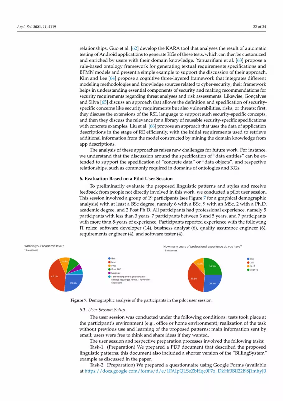
Appl. Sci. 2021, 11, 4119 22 of 34
relationships. Guo et al. [62] develop the KARA tool that analyses the result of automatictesting of Android applications to generate KGs of these tests, which can then be customizedand enriched by users with their domain knowledge. Yanuarifiani et al. [63] propose arule-based ontology framework for generating textual requirements specifications andBPMN models and present a simple example to support the discussion of their approach.Kim and Lee [64] propose a cognitive three-layered framework that integrates differentmodeling methodologies and knowledge sources related to cyber-security; their frameworkhelps in understanding essential components of security and making recommendations forsecurity requirements regarding threat analyses and risk assessments. Likewise, Gonçalvesand Silva [65] discuss an approach that allows the definition and specification of security-specific concerns like security requirements but also vulnerabilities, risks, or threats; first,they discuss the extensions of the RSL language to support such security-specific concepts,and then they discuss the relevance for a library of reusable security-specific specificationswith concrete examples. Liu et al. [66] propose an approach that uses the data of applicationdescriptions in the stage of RE efficiently, with the initial requirements used to retrieveadditional information from the model constructed by mining the domain knowledge fromapp descriptions.
The analysis of these approaches raises new challenges for future work. For instance,we understand that the discussion around the specification of “data entities” can be ex-tended to support the specification of “concrete data” or “data objects”, and respectiverelationships, such as commonly required in domains of ontologies and KGs.
6. Evaluation Based on a Pilot User Session
To preliminarily evaluate the proposed linguistic patterns and styles and receivefeedback from people not directly involved in this work, we conducted a pilot user session.This session involved a group of 19 participants (see Figure 7 for a graphical demographicanalysis) with at least a BSc degree, namely 6 with a BSc, 9 with an MSc, 2 with a Ph.D.academic degree, and 2 Post Ph.D. All participants had professional experience, namely 5participants with less than 3 years, 7 participants between 3 and 5 years, and 7 participantswith more than 5-years of experience. Participants reported experience with the followingIT roles: software developer (14), business analyst (6), quality assurance engineer (6),requirements engineer (4), and software tester (4).
Appl. Sci. 2021, 11, x FOR PEER REVIEW 22 of 34
Figure 7. Demographic analysis of the participants in the pilot user session.
6.1. User Session Setup The user session was conducted under the following conditions: tests took place at
the participant’s environment (e.g., office or home environment); realization of the task without previous use and learning of the proposed patterns; main information sent by email; users were free to think and share ideas if they wanted.
The user session and respective preparation processes involved the following tasks: Task-1: (Preparation) We prepared a PDF document that described the proposed lin-
guistic patterns; this document also included a shorter version of the “BillingSystem” ex-ample as discussed in the paper.
Task-2: (Preparation) We prepared a questionnaire using Google Forms (available at https://docs.google.com/forms/d/e/1FAIpQLSeZbHqc0F7z_DkHf0BiI22l98j1mhyJ0sqkjo-CeNCm8KHLMog/closedform (accessed on 15 April 2021)) consisting of 11 questions, in-cluding the following parts: 1. The first three questions were focused on the general characterization of the partici-
pant. 2. Five questions directly related to the assessment of the proposed patterns and their
styles; we first asked participants to rate in a 5-Likert scale (i.e., from 0 to 5, 0—Do not know, 1-Very Low, 2 -Low, 3-Medium, 4-High, and 5-Very High) how does she rate the proposed linguistic patterns, and How does she rate each linguistic style (i.e., CNL-A, CNL-B, RSL), in what concerns different specific qualities (i.e., simplicity, expressiveness, readability, and completeness).
3. Two additional questions were more time-consuming: the participant was chal-lenged to specify some entities informally referred in the case study (and not in-cluded in the PDF sent), namely specify the “Invoice”, “InvoiceLine” and “Cus-tomer” data entities; finally, the participants were invited to shortly explain her de-cisions and response.
4. The final question asked if the participant had some previous contact with text-based UML notations (e.g., TextUML, Umple, yUML) used for describing domain entities and if she gives advantages to the proposed linguistic styles and notations. Task-3: (Preparation) We prepared the list of participants and invited them to partic-
ipate in the user session; an email with clear instructions on how to complete the survey was sent to each participant and it was asked to fill in the evaluation questionnaire.
Task-4: (Execution) Each invited participant read the PDF document with the addi-tional instructions and performed autonomously the proposed tasks; in the end, they an-swered the evaluation questionnaire.
Task-5: (Analysis) We collected the responses submitted by the participants and an-alyzed their results.
6.2. Questionnaire Analysis As introduced above the questionnaire involves several questions grouped into four
dimensions of analysis.
Figure 7. Demographic analysis of the participants in the pilot user session.
6.1. User Session Setup
The user session was conducted under the following conditions: tests took place atthe participant’s environment (e.g., office or home environment); realization of the taskwithout previous use and learning of the proposed patterns; main information sent byemail; users were free to think and share ideas if they wanted.
The user session and respective preparation processes involved the following tasks:Task-1: (Preparation) We prepared a PDF document that described the proposed
linguistic patterns; this document also included a shorter version of the “BillingSystem”example as discussed in the paper.
Task-2: (Preparation) We prepared a questionnaire using Google Forms (availableat https://docs.google.com/forms/d/e/1FAIpQLSeZbHqc0F7z_DkHf0BiI22l98j1mhyJ0

Appl. Sci. 2021, 11, 4119 23 of 34
sqkjoCeNCm8KHLMog/closedform (accessed on 15 April 2021)) consisting of 11 questions,including the following parts:
1. The first three questions were focused on the general characterization of the participant.2. Five questions directly related to the assessment of the proposed patterns and their
styles; we first asked participants to rate in a 5-Likert scale (i.e., from 0 to 5, 0—Donot know, 1-Very Low, 2 -Low, 3-Medium, 4-High, and 5-Very High) how does sherate the proposed linguistic patterns, and How does she rate each linguistic style (i.e.,CNL-A, CNL-B, RSL), in what concerns different specific qualities (i.e., simplicity,expressiveness, readability, and completeness).
3. Two additional questions were more time-consuming: the participant was challengedto specify some entities informally referred in the case study (and not included in thePDF sent), namely specify the “Invoice”, “InvoiceLine” and “Customer” data entities;finally, the participants were invited to shortly explain her decisions and response.
4. The final question asked if the participant had some previous contact with text-basedUML notations (e.g., TextUML, Umple, yUML) used for describing domain entitiesand if she gives advantages to the proposed linguistic styles and notations.
Task-3: (Preparation) We prepared the list of participants and invited them to partici-pate in the user session; an email with clear instructions on how to complete the surveywas sent to each participant and it was asked to fill in the evaluation questionnaire.
Task-4: (Execution) Each invited participant read the PDF document with the ad-ditional instructions and performed autonomously the proposed tasks; in the end, theyanswered the evaluation questionnaire.
Task-5: (Analysis) We collected the responses submitted by the participants andanalyzed their results.
6.2. Questionnaire Analysis
As introduced above the questionnaire involves several questions grouped into fourdimensions of analysis.
First, after the questions related to the general characterization of each participant, thefirst question that requires the participants to rate was Q3:
Q3: How do you rate the proposed linguistic patterns (Data Entities, Data Attribute, DataConstraints, Cluster of Data Entities)?
Responses to this question revealed good to very good grades, as summarized inTable 4: Data Constraints patterns were rated slightly below 4 (i.e., 3.74), while the othershad the average ratings above or equal 4, namely: the average rating was 4.58 for DataEntity,4.53 for DataEntityCluster, and 4.0 for DataAttribute patterns in the 5-Likert scale (in which1 is Very Low and 5-Very High). We may also conclude that the more difficult to understandand to apply patterns (i.e., DataConstraint and DataAttribute patterns) were rated slightlylower than the others.
Table 4. How do participants rate the proposed linguistic patterns (values in a 1–5 scale)?
Linguistic Patterns Result
Data Entity (lp1) 4.58DataAttribute . . . (lp2) 4.00Data Constraint (lp3) 3.74Cluster of Data Entities (lp4) 4.53
Second, the questionnaire included 4 questions that asked participants to rank differentqualities (i.e., simplicity, expressiveness, readability, and completeness) of the discussedlinguistic patterns:
Q5: How do you rate the CNL-A linguistic style, in what concerns . . . ?Q6: How do you rate the CNL-B linguistic style, in what concerns . . . ?Q7: How do you rate the RSL linguistic style, in what concerns . . . ?

Appl. Sci. 2021, 11, 4119 24 of 34
Q8: Which notation is most appropriate for describing the proposed patterns?Concerning simplicity of CNL-A, CNL-B, and RSL (see Table 5 and Figure 8), partic-
ipants gave the highest score to CNL-A notation (the average score was 4.47), while thelowest score was given to RSL linguistic style (3.53). Additionally, CNL-B had the averagescore between these two scores (exactly 4). When expressiveness is considered, RSL wasthe best rated one, with a score of 4.21. CNL-A and CNL-B have similar average ratingswith regards to readability (4.32), while RSL is rated as the best one when completeness isconcerned (4.47).
Table 5. How do participants rate CNL-A, CNL-B, and RSL according to the following concerns(values in a 1–5 scale)?
Styles Simplicity Expressiveness Readability Completeness
CNL-A 4.47 3.58 4.32 3.54CNL-B 4.00 4.05 4.32 3.95RSL 3.53 4.21 3.89 4.47
Appl. Sci. 2021, 11, x FOR PEER REVIEW 24 of 34
Figure 8. Bar-chart on how participants rate the linguistic styles (values in a 1–5 scale).
According to the survey, ten (52.6%) participants responded that CNL-B was the most appropriate notation for describing the proposed patterns. This was followed by six participants (31.6%) that voted for CNL-A, and three (15.8%) voted for RSL. This result is a little surprising, considering that the average grades of all three notations are very close, but also understandable since RSL sentences are less simple and easy to read than the equivalents in CNL-A or CNL-B.
Third, the questionnaire included two open questions: Q9: According to the description of “BillingSystem” (See details in Appendix A) please spec-
ify the remaining entities (including the respective attributes, constraints, etc.), namely for “In-voice”, “InvoiceLine” and “Customer”, using your preferred notation. In particular, you may choose to use CNL-A, CNL-B, RSL, or even other textual notation.
Q10: Please, justify your decision regarding the previous question. Not all participants specified the remaining entities described in the case study, but
most did (15 of them). When performing a careful analysis of the submitted specifications, we noticed that participants mostly used CNL-B and RSL linguistic styles. All responses had the specification of the three asked entities: Customer, Invoice, and InvoiceLine. The style was generally fully complied with, but it was noted that a few of them did not ac-complish the specification of constraints.
The analysis of the comments led to the conclusion that it would be helpful for the participants to have an appropriate tool editor that would better support the writing of the chosen style.
Fourth, the questionnaire still included a final question: Q11: Comparing to other text-based UML notations (TextUML, Umple, yUML, etc.) for
describing the domain model do you give advantages to the proposed linguistic styles and notations (CNL-A, CNL-B, or RSL)?
Slightly more than half of the participants (11 of them) found it advantageous to pro-posed linguistic styles and notations than other text-based UML notations. Furthermore, 7 participants answered that the differences between these two groups are not that signif-icant, while 1 participant was not sure about it. Also, some participants referred that they like to use graphical notation to specify domain model and that it would be a plus to have some software tool to automatically produce such visual models from textual specifica-tions, and vice-versa.
Figure 8. Bar-chart on how participants rate the linguistic styles (values in a 1–5 scale).
According to the survey, ten (52.6%) participants responded that CNL-B was themost appropriate notation for describing the proposed patterns. This was followed by sixparticipants (31.6%) that voted for CNL-A, and three (15.8%) voted for RSL. This resultis a little surprising, considering that the average grades of all three notations are veryclose, but also understandable since RSL sentences are less simple and easy to read thanthe equivalents in CNL-A or CNL-B.
Third, the questionnaire included two open questions:Q9: According to the description of “BillingSystem” (See details in Appendix A) please
specify the remaining entities (including the respective attributes, constraints, etc.), namely for“Invoice”, “InvoiceLine” and “Customer”, using your preferred notation. In particular, you maychoose to use CNL-A, CNL-B, RSL, or even other textual notation.
Q10: Please, justify your decision regarding the previous question.Not all participants specified the remaining entities described in the case study, but
most did (15 of them). When performing a careful analysis of the submitted specifications,we noticed that participants mostly used CNL-B and RSL linguistic styles. All responses

Appl. Sci. 2021, 11, 4119 25 of 34
had the specification of the three asked entities: Customer, Invoice, and InvoiceLine. Thestyle was generally fully complied with, but it was noted that a few of them did notaccomplish the specification of constraints.
The analysis of the comments led to the conclusion that it would be helpful for theparticipants to have an appropriate tool editor that would better support the writing of thechosen style.
Fourth, the questionnaire still included a final question:Q11: Comparing to other text-based UML notations (TextUML, Umple, yUML, etc.) for
describing the domain model do you give advantages to the proposed linguistic styles and notations(CNL-A, CNL-B, or RSL)?
Slightly more than half of the participants (11 of them) found it advantageous toproposed linguistic styles and notations than other text-based UML notations. Further-more, 7 participants answered that the differences between these two groups are not thatsignificant, while 1 participant was not sure about it. Also, some participants referredthat they like to use graphical notation to specify domain model and that it would be aplus to have some software tool to automatically produce such visual models from textualspecifications, and vice-versa.
To summarize, the results gathered from this initial evaluation were generally encour-aging with positive scores in all the analyzed dimensions. Even that it can be stated thatthe number of participants of the session is relatively small, we consider this number issufficient to take meaningful conclusions because usability experts have noted that a groupof 5 testers is enough to uncover over 80% of the usability problems [67]. Also, since ourquestionnaire focuses on the usability of the patterns and writing styles, we think that19 participants is a reasonable number for an exploratory assessment, at least to identifychallenges on the usability of these aspects.
7. Conclusions
The specification of requirements describes technical concerns of a system and is usedthroughout several stages of its life cycle. A requirements specification document helps toshare the system vision among the main stakeholders, as well as facilitate the developmentand operation processes. The use of natural language for these specifications is widespreadand effective because humans can easily read and write them. However, natural languagealso exhibits inherent characteristics that often present as the root cause of many qualityproblems such as inconsistency, incompleteness, and ambiguousness.
Due to these problems, natural language specifications are often completed by somesort of other requirements and models that use controlled, formal, or semi-formal modelinglanguages, as extensively discussed in the related work section. These provide a set ofconstructs (e.g., data entity, actor, use case, or requirement) that explicitly or implicitlydefine its abstract syntax and semantics, and addresses different concerns and abstractionlevels. Also, these languages provide different notations or concrete syntaxes, such astextual, graphical, tabular, or even form-based representations. Furthermore, some authorshave proposed recommendations for better writing requirements; however, many of themare just general and abstract guidelines and hard to follow in practice.
We claim that it is needed better and more specific guidance to improve the wayrequirements engineers and product designers write and validate their specifications. Weargue that improving the awareness and knowledge of linguistic patterns, like the onesdiscussed in this paper, may contribute to enhance this current situation. On the otherhand, as showed throughout this paper with the CNL-A, CNL-B, and RSL languages,these linguistic patterns may be represented in practice by different writing styles, beingcompact (as with CNL-A), verbose and expressive (as CNL-B), or even based on a rigorousrequirements specification language (as with RSL). This discussion was supported by arepresentative yet simple and straightforward running example that allows illustrating,indeed, both the proposed patterns and associated writing styles. Additionally, AppendixA includes a visual representation of this example using the UML notation. This discussion
Appl. Sci. 2021, 11, 4119 26 of 34
was still complemented and validated within a pilot user session with 19 participants, ITprofessionals not directly involved in the research. The feedback received was generallyencouraging with positive scores in all the analyzed dimensions.
For future work, we plan to extend our research on linguistic patterns, namely foruse cases, user stories, goals, and other types of requirement-related elements. Also,different writing styles shall be explored, including mixing textual with tabular and visualrepresentations. We intend to explore and implement document automation featuresin this scope of RE, namely by automatically generate requirements specifications withdifferent writing styles from intermediate formats like the one defined with RSL or similar.Moreover, the patterns discussed shall be extended to consider data- and knowledge-drivenapproaches, such as those in the areas of knowledge graphs or linked data as discussed inthe related work section.
Author Contributions: Conceptualization, A.R.d.S.; formal analysis, A.R.d.S.; funding acquisition,A.R.d.S.; investigation, All; evaluation methodology, D.S.; supervision, A.R.d.S.; writing—originaldraft, A.R.d.S.; writing—review and editing, All. All authors have read and agreed to the publishedversion of the manuscript.
Funding: This research was partially funded by FCT UIDB/50021/2020 and 02/SAICT/2017/29360.The APC was funded by MDPI.
Institutional Review Board Statement: Not applicable.
Informed Consent Statement: Not applicable.
Acknowledgments: Work supported by funds under FCT UIDB/50021/2020 and 02/SAICT/2017/29360.
Conflicts of Interest: The authors declare no conflict of interest.
Appendix A. The BillingSystem Running Example
This paper uses a running example to support the explanation and discussion of theproposed linguistic patterns and linguistic styles. This example refers to the requirementsof a fictitious information system called “BillingSystem”, which is a simple invoice manage-ment system. The following text partially describes a diversity of its informal requirementsas adapted from the example initially introduced by Silva [18].
Appendix A.1. Informal and Annotated Informal Description
The following sentences informally describe the requirements of the BillingSystem:The BillingSystem is a system that allows its users to manage customers, products,and invoices. A user is someone that has a user account and is assigned toa user role, namely as operator, manager, administrator, and customer [ . . . ].The administrator may register users, which involves the following information:first and last names, email address, username, password, and user role [ . . . ].A VAT consists of the following information: VAT code, rate, name, and value.The VAT rates consider the following values: standard, reduced, and special.[ . . . ]A product consists of the following information: name, price, VAT rate,VAT value, and size category; a size category consists of one of the followingvalues: Small, Regular, Large, ExtraLarge. Product names are strings andprices are decimals. [ . . . ]A customer consists of the following information: name, fiscal id, image,bank information, and additional information such as address and personalcontacts. A customer can also be defined as a customer VIP, and in thissituation, there is a discount tax that can change over time.The operator shall create invoices with respective details defined as invoice lines.An invoice shall have the following information: customer id, dates (e.g.,of creation, approval, and paid), status (e.g., created, approved, rejected, paid,deleted), total value with and without VAT. Also, an invoice line shall includeproduct id, number of items, product value with and without VAT [ . . . ].
For the sake of readability, we may highlight special text fragments of these sentencesas follows: candidate data entities are marked with bold text; data entity attributes are

Appl. Sci. 2021, 11, 4119 27 of 34
marked with light gray background color (e.g., product name, product values, VAT code,
and value); data enumeration values are marked with light green background color(e.g., Small, Regular and Large):The BillingSystem is a system that allows its users to manage customers, products,and invoices. A user is someone that has a user account and is assigned to auser role, namely as operator, manager, administrator, and customer [ . . . ].The administrator may register users, which involves the following information:first and last names, email address, username, password, and user role [ . . . ].
A VAT consists of the following information: VAT code, rate, name, and value .
The VAT rates consider the following values: standard, reduced, and special .[ . . . ]A product consists of the following information: name, price, VAT rate, VAT value,
and size category ; a size category consists of one of the following values:
Small, Regular, Large, and ExtraLarge . Product names are strings and pricesare decimals. [ . . . ]A customer consists of the following information: name, fiscal id, image,
bank information, and additional information such as address and personal contacts .A customer can also be defined as a customer VIP, and in this situation,there is a discount tax that can change over time.The operator shall create invoices with respective details defined as invoice lines.An invoice shall have the following information: customer id, dates (e. g., of
creation, approval, and paid), status (e.g., created , approved, rejected, paid,
deleted), total value with and without VAT . Also, an invoice line shall include
product id, number of items, product value with and without VAT [ . . . ].
The following text fragments describe the data entity’s related elements specified withthe CNL-A, CNL-B, RSL, and UML languages. For the sake of conciseness, these fragmentspresent a complete specification for only the VAT, Product, Invoice, and InvoiceLine dataentities (the remaining elements are suggested as an exercise to the interested reader).
Appendix A.2. Data Entities Represented with a Compact Writing Style (CNL-A)
DataEnumerations:UserRoleKind DataEnumeration with values: Admin, Manager, Operator, Customer.VATRateKind DataEnumeration with values: Standard, Reduced, Special.SizeKind DataEnumeration with values: Small Regular Large ExtraLarge.InvoiceStatusKind DataEnumeration with values: Pending, Approved, Rejected,Paid, Deleted.
DataEntities:e_VAT Reference DataEntity with attributes: Code (PK), Rate (NotNull), Name,
Value (NotNull).e_Product Master DataEntity with attributes: ID (PK), Name (“1..2”), VATCode
(NotNull FK(e_VAT)), VATValue (NotNull Derived), valueWithoutVAT (NotNull),valueWithVAT (NotNull Derived), size.
e_Invoice is a Regular Document DataEntity with attributes: ID (PK), customerId(NotNull FK(e_Customer)), creationDate (NotNull), approvalDate, paidDate, status,valueWithoutVAT (Derived), valueWithVAT (Derived).
e_InvoiceLine is a Weak Document DataEntity with attributes: ID (PK), invoiceID(NotNull FK(e_Invoice)),productID (NotNull FK(e_Product)), numberItems, productVAT(NotNull Derived), productPriceWithoutVAT (NotNull Derived).
e_Customer is a Master DataEntity [ . . . ].e_CustomerVIP is a Master DataEntity, extends e_Customer [ . . . ].
e_User is a Master DataEntity [ . . . ].
DataEntityClusters:ec_Customer Master DataEntityCluster with main e_Customer.ec_Product Master DataEntityCluster with main e_Product, uses e_VAT.ec_Invoice is a Document DataEntityCluster with main e_Invoice,
child e_InvoiceLine, uses e_Customer.ec_Invoice_Simple Document DataEntityCluster with main e_Invoice, uses e_Customer.
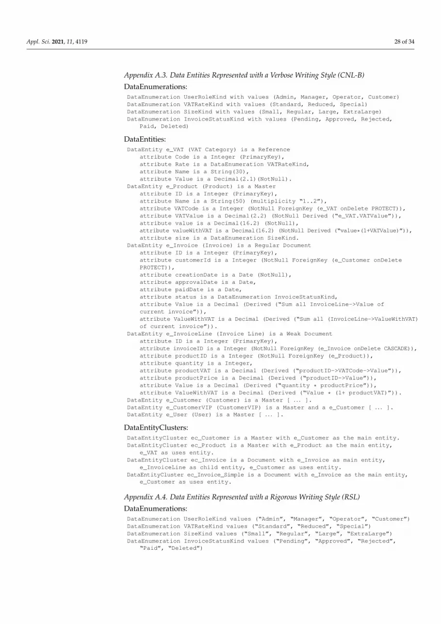
Appl. Sci. 2021, 11, 4119 28 of 34
Appendix A.3. Data Entities Represented with a Verbose Writing Style (CNL-B)
DataEnumerations:DataEnumeration UserRoleKind with values (Admin, Manager, Operator, Customer)DataEnumeration VATRateKind with values (Standard, Reduced, Special)DataEnumeration SizeKind with values (Small, Regular, Large, ExtraLarge)DataEnumeration InvoiceStatusKind with values (Pending, Approved, Rejected,
Paid, Deleted)
DataEntities:DataEntity e_VAT (VAT Category) is a Reference
attribute Code is a Integer (PrimaryKey),attribute Rate is a DataEnumeration VATRateKind,attribute Name is a String(30),attribute Value is a Decimal(2.1)(NotNull).
DataEntity e_Product (Product) is a Masterattribute ID is a Integer (PrimaryKey),attribute Name is a String(50) (multiplicity “1..2”),attribute VATCode is a Integer (NotNull ForeignKey (e_VAT onDelete PROTECT)),attribute VATValue is a Decimal(2.2) (NotNull Derived (“e_VAT.VATValue”)),attribute value is a Decimal(16.2) (NotNull),attribute valueWithVAT is a Decimal(16.2) (NotNull Derived (“value*(1+VATValue)”)),attribute size is a DataEnumeration SizeKind.
DataEntity e_Invoice (Invoice) is a Regular Documentattribute ID is a Integer (PrimaryKey),attribute customerId is a Integer (NotNull ForeignKey (e_Customer onDeletePROTECT)),attribute creationDate is a Date (NotNull),attribute approvalDate is a Date,attribute paidDate is a Date,attribute status is a DataEnumeration InvoiceStatusKind,attribute Value is a Decimal (Derived (“Sum all InvoiceLine->Value ofcurrent invoice”)),attribute ValueWithVAT is a Decimal (Derived (“Sum all (InvoiceLine->ValueWithVAT)of current invoice”)).
DataEntity e_InvoiceLine (Invoice Line) is a Weak Documentattribute ID is a Integer (PrimaryKey),attribute invoiceID is a Integer (NotNull ForeignKey (e_Invoice onDelete CASCADE)),attribute productID is a Integer (NotNull ForeignKey (e_Product)),attribute quantity is a Integer,attribute productVAT is a Decimal (Derived (“productID->VATCode->Value”)),attribute productPrice is a Decimal (Derived (“productID->Value”)),attribute Value is a Decimal (Derived (“quantity * productPrice”)),attribute ValueWithVAT is a Decimal (Derived (“Value * (1+ productVAT)”)).
DataEntity e_Customer (Customer) is a Master [ . . . ].DataEntity e_CustomerVIP (CustomerVIP) is a Master and a e_Customer [ . . . ].DataEntity e_User (User) is a Master [ . . . ].
DataEntityClusters:DataEntityCluster ec_Customer is a Master with e_Customer as the main entity.DataEntityCluster ec_Product is a Master with e_Product as the main entity,
e_VAT as uses entity.DataEntityCluster ec_Invoice is a Document with e_Invoice as main entity,
e_InvoiceLine as child entity, e_Customer as uses entity.DataEntityCluster ec_Invoice_Simple is a Document with e_Invoice as the main entity,
e_Customer as uses entity.
Appendix A.4. Data Entities Represented with a Rigorous Writing Style (RSL)
DataEnumerations:DataEnumeration UserRoleKind values (“Admin”, “Manager”, “Operator”, “Customer”)DataEnumeration VATRateKind values (“Standard”, “Reduced”, “Special”)DataEnumeration SizeKind values (“Small”, “Regular”, “Large”, “ExtraLarge”)DataEnumeration InvoiceStatusKind values (“Pending”, “Approved”, “Rejected”,
“Paid”, “Deleted”)
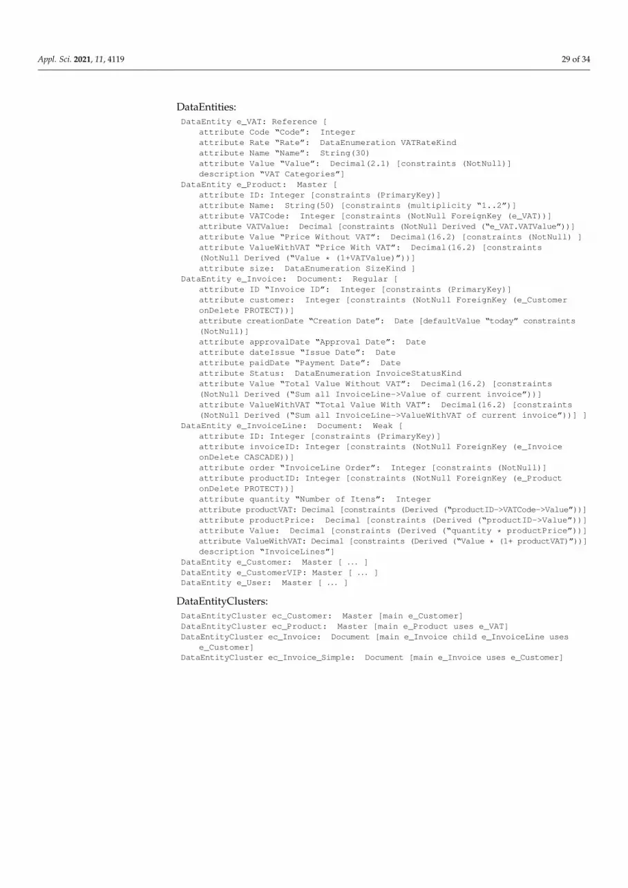
Appl. Sci. 2021, 11, 4119 29 of 34
DataEntities:DataEntity e_VAT: Reference [
attribute Code “Code”: Integerattribute Rate “Rate”: DataEnumeration VATRateKindattribute Name “Name”: String(30)attribute Value “Value”: Decimal(2.1) [constraints (NotNull)]description “VAT Categories”]
DataEntity e_Product: Master [attribute ID: Integer [constraints (PrimaryKey)]attribute Name: String(50) [constraints (multiplicity “1..2”)]attribute VATCode: Integer [constraints (NotNull ForeignKey (e_VAT))]attribute VATValue: Decimal [constraints (NotNull Derived (“e_VAT.VATValue”))]attribute Value “Price Without VAT”: Decimal(16.2) [constraints (NotNull) ]attribute ValueWithVAT “Price With VAT”: Decimal(16.2) [constraints(NotNull Derived (“Value * (1+VATValue)”))]attribute size: DataEnumeration SizeKind ]
DataEntity e_Invoice: Document: Regular [attribute ID “Invoice ID”: Integer [constraints (PrimaryKey)]attribute customer: Integer [constraints (NotNull ForeignKey (e_CustomeronDelete PROTECT))]attribute creationDate “Creation Date”: Date [defaultValue “today” constraints(NotNull)]attribute approvalDate “Approval Date”: Dateattribute dateIssue “Issue Date”: Dateattribute paidDate “Payment Date”: Dateattribute Status: DataEnumeration InvoiceStatusKindattribute Value “Total Value Without VAT”: Decimal(16.2) [constraints(NotNull Derived (“Sum all InvoiceLine->Value of current invoice”))]attribute ValueWithVAT “Total Value With VAT”: Decimal(16.2) [constraints(NotNull Derived (“Sum all InvoiceLine->ValueWithVAT of current invoice”))] ]
DataEntity e_InvoiceLine: Document: Weak [attribute ID: Integer [constraints (PrimaryKey)]attribute invoiceID: Integer [constraints (NotNull ForeignKey (e_InvoiceonDelete CASCADE))]attribute order “InvoiceLine Order”: Integer [constraints (NotNull)]attribute productID: Integer [constraints (NotNull ForeignKey (e_ProductonDelete PROTECT))]attribute quantity “Number of Itens”: Integerattribute productVAT: Decimal [constraints (Derived (“productID->VATCode->Value”))]attribute productPrice: Decimal [constraints (Derived (“productID->Value”))]attribute Value: Decimal [constraints (Derived (“quantity * productPrice”))]attribute ValueWithVAT: Decimal [constraints (Derived (“Value * (1+ productVAT)”))]description “InvoiceLines”]
DataEntity e_Customer: Master [ . . . ]DataEntity e_CustomerVIP: Master [ . . . ]DataEntity e_User: Master [ . . . ]
DataEntityClusters:DataEntityCluster ec_Customer: Master [main e_Customer]DataEntityCluster ec_Product: Master [main e_Product uses e_VAT]DataEntityCluster ec_Invoice: Document [main e_Invoice child e_InvoiceLine uses
e_Customer]DataEntityCluster ec_Invoice_Simple: Document [main e_Invoice uses e_Customer]
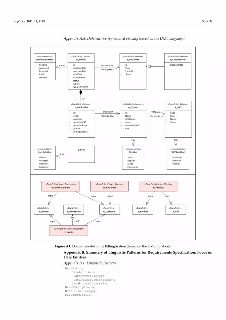
Appl. Sci. 2021, 11, 4119 30 of 34
Appendix A.5. Data entities represented visually (based on the UML language)
Appl. Sci. 2021, 11, x FOR PEER REVIEW 29 of 33
attribute ValueWithVAT: Decimal [constraints (Derived (“Value * (1+ product-VAT)”))]
description “InvoiceLines”] DataEntity e_Customer: Master […] DataEntity e_CustomerVIP: Master […] DataEntity e_User: Master […]
DataEntityClusters: DataEntityCluster ec_Customer: Master [main e_Customer] DataEntityCluster ec_Product: Master [main e_Product uses e_VAT] DataEntityCluster ec_Invoice: Document [main e_Invoice child e_InvoiceLine uses
e_Customer] DataEntityCluster ec_Invoice_Simple: Document [main e_Invoice uses e_Customer]
Appendix A.5. Data entities represented visually (based on the UML language)
Figure A1. Domain model of the BillingSystem (based on the UML notation).
Appendix B. Summary of Linguistic Patterns for Requirements Specification: Focus on Data Entities Appendix B.1. Linguistic Patterns DataEntity
Figure A1. Domain model of the BillingSystem (based on the UML notation).
Appendix B. Summary of Linguistic Patterns for Requirements Specification: Focus onData Entities
Appendix B.1. Linguistic PatternsDataEntity
DataAttributeDataAttributeTypeDataAttributeConstraint
DataEntityConstraintDataEntityClusterDataPrimitiveTypeDataEnumeration

Appl. Sci. 2021, 11, 4119 31 of 34
Appendix B.2. Common VocabularyDataEntity
DataEntityType: Parameter | Reference | Master | Document | TransactionDataEntitySubType: Regular | WeakDataAttribute:DataAttributeType: DataPrimitiveType | DataEnumerationDataAttributeConstraint:Multiplicity(<expression>),PrimaryKey, NotNull, Unique, ReadOnly, Encrypted,Derived(<expression>),ForeignKey(targetDataEntity, onDeleteType(CASCADE | PROTECT | SET_NULL)),Check(<expression>)
DataEntityConstraint:ReadOnly, Encrypted,Check(<expression>)
DataEntityCluster:DataEntityClusterType: Parameter | Reference | Master | Document | Transactionmain:DataEntitydetails:DataEntityreferences:DataEntity
DataPrimitiveType: Integer | Double | Boolean | Date | Time | Datetime | String| etc.DataEnumeration
Appendix B.3. Data Entities’ Linguistic Patterns defined with CNL-B Notation
DataEnumerations:DataEnumeration DataEntityType with values
(Parameter, Reference, Master, Document, Transaction, Other).DataEnumeration DataEntitySubType with values
(Regular, Weak, Other).DataEnumeration DataEntityClusterType with values
(Parameter, Reference, Master, Document, Transaction, Other).DataEnumeration DataAttributeType with values
(Integer, Double, Decimal, Boolean, Date, Time, Datetime, String).DataEnumeration ForeignKeyOnDeleteType with values
(CASCADE, PROTECT, SET_NULL, SET_DEFAULT).
DataEntities:DataEntity DataEnumeration is a Reference
attribute id is a String (NotNull Unique),attribute name is a String,attribute values is a String (multiplicity "1..*"),attribute description is a String.
DataEntity DataEntity is a Regular Masterattribute id is a String (NotNull Unique),attribute name is a String,attribute type is a DataEnumeration DataEntityType (NotNull),attribute subType is a DataEnumeration DataEntitySubType,attribute isA is a String (ForeignKey (DataEntity onDelete PROTECT)),attribute description is a String.
DataEntity DataAttribute is a Weak Masterattribute id is a String (NotNull Unique),attribute name is a String,attribute type is a DataEnumeration DataAttributeType,attribute typeAlternative is a String,attribute defaultValue is a String,attribute multiplicity is a String,attribute isPrimaryKey is a Boolean,attribute isNotNull is a Boolean,attribute isUnique is a Boolean,attribute isDerived is a Boolean,attribute isReadOnly is a Boolean,attribute isEncrypted is a Boolean,attribute foreignKey_Target is a String (ForeignKey (DataEntity)),attribute foreignKey_onDeleteType DataEnumeration ForeignKeyOnDeleteType,attribute checkExpressions is a String (multiplicity "*").
DataEntity DataEntityCluster is a Masterattribute id is a String (NotNull Unique),

Appl. Sci. 2021, 11, 4119 32 of 34
attribute type is a DataEnumeration DataEntityClusterType,attribute main is a String (ForeignKey (DataEntity)),|attribute children is a String (multiplicity "*" ForeignKey (DataEntity)),attribute uses is a String (multiplicity "*" ForeignKey (DataEntity)),attribute description is a String.
References1. Pohl, K. Requirements Engineering: Fundamentals, Principles, and Techniques; Springer: Berlin/Heidelberg, Germany, 2010.2. Robertson, S.; Robertson, J. Mastering the Requirements Process, 2nd ed.; Addison-Wesley: Boston, MA, USA, 2006.3. Eveleens, L.; Verhoef, C. The Rise and Fall of the Chaos Report Figures. IEEE Softw. 2010, 27, 30. [CrossRef]4. Standish Group. Chaos Summary 2009 Report: The 10 Laws of Chaos; Standish Group: Boston, MA, USA, 2009.5. Kovitz, B. Practical Software Requirements: Manual of Content and Style; Manning: Shelter Island, NY, USA, 1998.6. Withall, S. Software Requirements Patterns; Microsoft Press: Redmond, WA, USA, 2007.7. Verelst, J.; Silva, A.R.; Mannaert, H.; Ferreira, D.A.; Huysmans, P. Identifying Combinatorial Effects in Requirements Engineering.
In Proceedings of the Third Enterprise Engineering Working Conference (EEWC 2013), Luxembourg, 13–14 May 2013.8. Luisa, M.; Mariangela, F.; Pierluigi, N.I. Market research for requirements analysis using linguistic tools. Requir. Eng. 2004, 9,
40–56. [CrossRef]9. Fernández, D.M.; Wagner, S.; Kalinowski, M.; Felderer, M.; Mafra, P.; Vetrò, A.; Conte, T.; Christiansson, M.T.; Greer, D.; Lassenius,
C.; et al. Naming the Pain in Requirements Engineering: Contemporary Problems, Causes, and Effects in Practice. Empir. Softw.Eng. 2017, 22, 2298–2338. [CrossRef]
10. Zhao, L.; Alhoshan, W.; Ferrari, A.; Letsholo, K.J.; Ajagbe, M.A.; Chioasca, E.V.; Batista-Navarro, R.T. Natural Language Processing(NLP) for Requirements Engineering: A Systematic Mapping Study. arXiv 2020, arXiv:2004.01099.
11. Videira, C.; Silva, A.R. Patterns and metamodel for a natural-language-based requirements specification language. In Proceedingsof the 17th Conference on Advanced Information Systems Engineering (CAiSE’05 Forum), Porto, Portugal, 13–17 June 2005.
12. Videira, C.; Ferreira, D.; Silva, A.R. A linguistic patterns approach for requirements specification. In Proceedings of the 32ndEuromicro Conference on Software Engineering and Advanced Applications (Euromicro’2006), Cavtat, Croatia, 29 August–1September 2006.
13. Chung, L.; Nixon, B.A.; Yu, E.; Mylopoulos, J. Non-Functional Requirements in Software Engineering; Kluwer Academic: Dordrecht,The Netherlands, 2000.
14. Cockburn, A. Writing Effective Use Cases; Addison-Wesley: Boston, MA, USA, 2001.15. Fernandes, J.M.; Machado, R.J. Requirements in Engineering Projects; Springer: Berlin/Heidelberg, Germany, 2016.16. DeCapua, A. Grammar for Teachers: A Guide to American English for Native and Non-Native Speakers; Springer: Berlin/Heidelberg,
Germany, 2008.17. Durán, A.; Bernárdez, B.; Toro, M.; Corchuelo, R.; Ruiz, A.; Pérez, J. Expressing customer requirements using natural language
requirements templates and patterns. In Proceedings of the 3rd IMACS/IEEE International Multiconference on: Circuits, Systems,Communications and Computers (CSCC’99), Athens, Greece, 4–8 July 1999.
18. Silva, A.R. Linguistic Patterns and Linguistic Styles for Requirements Specification (I): An Application Case with the Rig-orous RSL/Business-level Language. In Proceedings of the 22nd European Conference on Pattern Languages of Programs(EuroPLOP’2017), Irsee, Germany, 12–16 July 2017.
19. Chen, P. The entity-relationship model—toward a unified view of data. ACM Trans. Database Syst. 1976, 1, 9–36. [CrossRef]20. Chen, P. English Sentence Structure and Entity-Relationship Diagrams. Inf. Sci. 1983, 29, 127–149. [CrossRef]21. Object Management Group. Unified Modeling Language; Version 2.5.1; OMG: Milford, MA, USA, 2017; Available online: http:
//www.omg.org/spec/UML/ (accessed on 15 April 2021).22. McGuinness, D.L.; Van Harmelen, F. OWL web ontology language overview. W3C Recomm. 2004, 10, 1–22.23. Hitzler, P.; Krötzsch, M.; Parsia, B.; Patel-Schneider, P.F.; Rudolph, S. OWL 2 web ontology language primer. W3C Recomm. 2009,
27, 123.24. International Organization for Standardization. ISO/IEC 9075-1:2016: Information Technology—Database Languages—SQL—Part 1:
Framework (SQL/Framework); ISO: Geneva, Switzerland, 2016.25. Da Silva, A.R. Model-driven engineering: A survey supported by the unified conceptual model. Comput. Lang. Syst. Struct. 2015,
43, 139–155.26. Hutchinson, J.; Rouncefield, M.; Whittle, J. Model-driven engineering practices in industry. In Proceedings of the 33rd Interna-
tional Conference on Software Engineering, Honolulu, HI, USA, 21–28 May 2011; pp. 633–642.27. Bozyigit, F.; Aktas, Ö.; Kılınç, D. Linking software requirements and conceptual models: A systematic literature review. Eng. Sci.
Technol. Int. J. 2021, 24, 71–82.28. Bork, D.; Karagiannis, D.; Pittl, B. A survey of modeling language specification techniques. Inf. Syst. 2020, 87, 101425. [CrossRef]29. Schön, E.M.; Thomaschewski, J.; Escalona, M.J. Agile Requirements Engineering: A systematic literature review. Comput. Stand.
Interfaces 2017, 49, 79–91. [CrossRef]30. Cabot, J. Text to UML and Other “Diagrams as Code” Tools—Fastest Way to Create Your Models. 2020. Available online:
https://modeling-languages.com/ (accessed on 1 April 2021).

Appl. Sci. 2021, 11, 4119 33 of 34
31. Fuchs, N.E.; Kaljurand, K.; Kuhn, T. Attempto controlled English for knowledge representation. In Proceedings of the 4thInternational Reasoning Web Summer School 2008, Venice, Italy, 7–11 September 2008; pp. 104–124.
32. Schneider, S. The B-Method: An Introduction; Palgrave Macmillan: London, UK, 2001.33. Kuhn, T. A Survey and Classification of Controlled Natural Languages. Comput. Linguist. 2014, 40, 121–170. [CrossRef]34. Silva, A.R. Rigorous Specification of Use Cases with the RSL Language. In Proceedings of the 28th International Conference on
Information Systems Development (ISD’2019), Toulon, France, 28–30 August 2019.35. Bettini, L. Implementing Domain-Specific Languages with Xtext and Xtend; Packt Publishing Ltd.: Birmingham, UK, 2016.36. Microsoft. Data Entities Overview: Categories of Entities, Dynamics 365 White Paper. 2019. Available online: https://docs.
microsoft.com/en-us/dynamics365/fin-ops-core/dev-itpro/data-entities/data-entities#categories-of-entities (accessed on 1April 2021).
37. Ramakrishnan, R.; Gehrke, J. Database Management Systems, 3rd ed.; McGraw-Hill: New York, NY, USA, 2012.38. Connolly, T.M.; Begg, C.E. Database Systems: A Practical Approach to Design, Implementation, and Management, 6th ed.; Pearson
Education: London, UK, 2014.39. Lamsweerde, A. Requirements Engineering: From System Goals to UML Models to Software Specifications; Wiley: Hoboken, NJ, USA,
2009.40. Institute of Electrical and Electronics Engineers. IEEE Std 830-1998, IEEE Recommended Practice for Software Requirements Specifica-
tions; IEEE: New York, NY, USA, 1998.41. Mernik, M.; Heering, J.; Sloane, A. When and how to develop domain-specific languages. ACM Comput. Surv. 2005, 37, 316–344.
[CrossRef]42. Ribeiro, A.; Silva, A.; da Silva, A.R. Data Modeling and Data Analytics: A Survey from a Big Data Perspective. J. Softw. Eng. Appl.
2015, 8, 617–634. [CrossRef]43. Tudorache, T. Ontology engineering: Current state, challenges, and future directions. Semant. Web 2020, 11, 1–14. [CrossRef]44. Vigo, M.; Bail, S.; Jay, C.; Stevens, R.D. Overcoming the pitfalls of ontology authoring: Strategies and implications for tool design.
Int. J. Hum. Comput. Stud. 2014, 72, 835–845. [CrossRef]45. Jackson, D. Software Abstractions: Logic, Language, and Analysis; The MIT Press: Cambridge, MA, USA, 2012.46. Abrial, J.-R.; Lee, M.K.O.; Neilson, D.S.; Scharbach, P.N.; Sørensen, I.H. The B-method. In Proceedings of the 4th International
Symposium of VDM Europe (VDM’91), Noordwijkerhout, The Netherlands, 21–25 October 1991.47. Foster, H.D.; Krolnik, A.C.; Lacey, D.J. Assertion-Based Design; Springer: Berlin/Heidelberg, Germany, 2004.48. Sommerville, I.; Sawyer, P. Requirements Engineering: A Good Practice Guide; Wiley: Hoboken, NJ, USA, 1997.49. Schwitter, R. Controlled natural languages for knowledge representation. In Proceedings of the COLING ‘10: Proceedings of the
23rd International Conference on Computational Linguistics, Beijing, China, 23–27 August 2021; Association for ComputationalLinguistics: Stroudsburg, PA, USA, 2010; pp. 1113–1121.
50. Hossain, B.A.; Schwitter, R. Semantic Round-Tripping in Conceptual Modelling Using Restricted Natural Language. In Proceed-ings of the Australasian Database Conference, Melbourne, VIC, Australia, 3–7 February 2020; pp. 3–15.
51. Savic, D.; Vlajic, S.; Lazarevic, S.; Antovic, I.; Stanojevic, V.; Milic, M.; Silva, A.R. SilabMDD: A Use Case Model-Driven Approach.In Proceedings of the ICIST 2015 5th International Conference on Information Society and Technology, Kopaonik, Serbia, 8–11March 2015.
52. Object Management Group. System Modeling Language; Version 1.5; OMG: Milford, MA, USA, 2017; Available online: http://www.omg.org/spec/SysML/ (accessed on 1 April 2021).
53. Chen, A.; Beatty, J. Visual Models for Software Requirements; Microsoft Press: Redmond, WA, USA, 2012.54. Ribeiro, A.; Silva, A.R. XIS-Mobile: A DSL for Mobile Applications. In Proceedings of the 29th Annual ACM Symposium on
Applied Computing (SAC), Gyeongju, Korea, 24–28 March 2014.55. Ribeiro, A.; Silva, A.R. Evaluation of XIS-Mobile, a Domain Specific Language for Mobile Application Development. J. Softw. Eng.
Appl. 2014, 7, 906–919. [CrossRef]56. Seixas, J.; Ribeiro, A.; Silva, A.R. A Model-Driven Approach for Developing Responsive Web Apps. In Proceedings of the 14th
International Conference on Evaluation of Novel Approaches to Software Engineering (ENASE’2019), Heraklion, Greece, 4–5May 2019.
57. Silva, A.R.; Saraiva, J.; Silva, R.; Martins, C. XIS—UML Profile for eXtreme Modeling Interactive Systems. In Proceedings of the4th International Workshop on Model Based Methodologies for Pervasive and Embedded Software (MOMPES’2007), Braga,Portugal, 31 March 2007.
58. Gamito, I.; Silva, A.R. From Rigorous Requirements and User Interfaces Specifications into Software Business Applications.2020. In Proceedings of the 13th International Conference on the Quality of Information and Communications Technology(QUATIC’2020), Braga, Portugal, 8–11 September 2020.
59. Wang, Q.; Mao, Z.; Wang, B.; Guo, L. Knowledge graph embedding: A survey of approaches and applications. IEEE Trans. Knowl.Data Eng. 2017, 29, 2724–2743. [CrossRef]
60. Hogan, A.; Blomqvist, E.; Cochez, M.; d’Amato, C.; de Melo, G.; Gutierrez, C.; Gayo, J.E.L.; Kirrane, S.; Neumaier, S.; Polleres,A.; et al. Knowledge graphs. arXiv 2020, arXiv:2003.02320.
Appl. Sci. 2021, 11, 4119 34 of 34
61. Pan, Z.; Zhuang, X.; Ren, J.; Zhang, X. Pattern-Based Knowledge Graph Embedding for Non-functional Requirements. In Pro-ceedings of the 6th International Conference on Dependable Systems and Their Applications (DSA’2019), Harbin, China, 3–6January 2020.
62. Guo, C.; He, T.; Yuan, W.; Guo, Y.; Hao, R. Crowdsourced requirements generation for automatic testing via knowledge graph. InProceedings of the 29th ACM SIGSOFT International Symposium on Software Testing and Analysis, Virtual Conference, LosAngeles, CA, USA, 18–22 July 2020.
63. Yanuarifiani, A.P.; Chua, F.F.; Chan, G.Y. Feasibility Analysis of a Rule-Based Ontology Framework (ROF) for Au-to-Generation ofRequirements Specification. In Proceedings of the 2020 IEEE 2nd International Conference on Artificial Intelligence in Engineeringand Technology (IICAIET’2020), Kota Kinabalu, Malaysia, 26–27 September 2020.
64. Kim, B.J.; Lee, S.W. Understanding and recommending security requirements from problem domain ontology: A cognitivethree-layered approach. J. Syst. Softw. 2020, 169, 110695. [CrossRef]
65. Gonçalves, L.; Silva, A. Towards a Catalogue of Reusable Security Requirements, Risks and Vulnerabilities. In Proceedings of the27th International Conference on Information Systems Development (ISD’2018), Lund, Sweden, 22–24 August 2018.
66. Liu, Y.; Liu, L.; Liu, H.; Li, S. Information recommendation based on domain knowledge in app descriptions for improving thequality of requirements. IEEE Access 2019, 7, 9501–9514. [CrossRef]
67. Nielsen, J.; Landauer, T.K. A Mathematical Model of the Finding of Usability Problems. In Proceedings of the INTERACT’93 andCHI’93 Conference on Human Factors in Computing Systems, Amsterdam, The Netherlands, 24–29 April 1993.