
A multiple view system for modeling building entities
10
A Multiple View System for Modeling Building Entities Frank Steinicke, Timo Ropinski, Klaus Hinrichs, Gerd Bruder Institut f ¨ ur Informatik, Westf¨ alische Wilhelms-Universit¨ at M ¨ unster {fsteini,ropinski,khh,g brud01}@math.uni-muenster.de Abstract Modeling virtual buildings is an essential task in the city planning domain whereas several aspects have essen- tial influence. Planners have to deal with different types of potentially multiform datasets; moreover they have to con- sider certain guidelines and constraints that are imposed on the development areas to which buildings are related. The planning process can be divided into different subtasks with varying requirements regarding the interaction tech- niques that are used for their accomplishment. To incorpo- rate these aspects multiple view systems have proven enor- mous potential in order to provide efficient user interfaces. In this paper, we present strategies for modeling virtual building entities via a multiple view system as part of a 3D decision support system that enables the intuitive genera- tion and evaluation of building proposals. City planners have been involved in the design process of the system, in particular the multiple view concepts. Therefore each view of the system, which visualizes different aspects concerning the underlying models, meets the demands of city planners. Furthermore, we present both coupled and uncoupled in- teraction techniques between different views with respect to requirements of the city planning domain. Keywords— Geovisualization, city planning, building enti- ties, multiple view systems, coupling techniques 1 Introduction City planning tasks are of major importance for civil works since both the environment and the inhabitants of a city are affected. The cityscape as well as the quality of life of the residents essentially depend on the appearance of different entities such as road networks, planting, green spaces, and recreation areas, and in particular buildings. To define such virtual buildings city planners usually use two-dimensional CAD concepts to design the develop- ment for a certain area based on existing cadastral data, which is available for every town in Germany. Based on this cadastral data city planners define development plans as depicted in Figure 1 (a). Development plans incorporate several geospecific entities, e.g., buildings and recreation areas, associated with a set of constraints, which specify what types of geoobjects are allowed and what require- ments have to be incorporated. When a development plan is provided city planners can design several geoobjects, in particular building entities, which are associated to certain buildings areas in the plan. When finishing this design pro- cess, the resulting design plan illustrates, for instance, po- tential home buyers how the residential area will look like. As depicted in Figure 1 (a) the data of development or design plans usually contains building footprints, road net- works, parcel boundaries and other information in a vector- based format. A virtual building defined in this format is stored by means of the building footprint, number of floors and floor’s height, roof type and further information given by numerical or textual hints. Figure 1 (b) shows the cadas- tral information for an example building of the develop- ment plan illustrated in Figure 1 (a). The outlines define the building footprint. The hatching enclosed by the outlines determines the type of roof. In this case a diagonal hatch- ing denotes a gabled roof, whereas, for instance, vertical straight lines specify a flat roof. Numerical values in the outline encode further information, e.g., roman numbers represent the number of stories, and textual information en- codes the address. Figure 1 (c) illustrates the correspond- ing 3D virtual buildings automatically generated from this two-dimensional vector data. One drawback when using such 2D CAD concepts is that they do not allow a realistic 3D preview of the build- ing regarding facades, roof types, and its integration into surrounding properties. To facilitate a realistic impres- sion of how a building would visually integrate into the environment and to enable communication regarding de- velopment proposals, two approaches are commonly used. One approach is to deliver the development plan to an architectural office. On the basis of this plan architects generate virtual 3D models and return exemplary three- dimensional visualizations of these planned areas to city planners. This procedure has the following two major shortcomings. First, the returned visualizations are static insofar as city planners cannot explore the 3D models in- teractively. Second, city planners cannot perform modifi-
Transcript of A multiple view system for modeling building entities
A Multiple View System for Modeling Building Entities
Frank Steinicke, Timo Ropinski, Klaus Hinrichs, Gerd BruderInstitut fur Informatik, Westfalische Wilhelms-Universitat Munster
{fsteini,ropinski,khh,g brud01}@math.uni-muenster.de
AbstractModeling virtual buildings is an essential task in the
city planning domain whereas several aspects have essen-tial influence. Planners have to deal with different types ofpotentially multiform datasets; moreover they have to con-sider certain guidelines and constraints that are imposedon the development areas to which buildings are related.The planning process can be divided into different subtaskswith varying requirements regarding the interaction tech-niques that are used for their accomplishment. To incorpo-rate these aspects multiple view systems have proven enor-mous potential in order to provide efficient user interfaces.In this paper, we present strategies for modeling virtualbuilding entities via a multiple view system as part of a 3Ddecision support system that enables the intuitive genera-tion and evaluation of building proposals. City plannershave been involved in the design process of the system, inparticular the multiple view concepts. Therefore each viewof the system, which visualizes different aspects concerningthe underlying models, meets the demands of city planners.Furthermore, we present both coupled and uncoupled in-teraction techniques between different views with respectto requirements of the city planning domain.
Keywords—Geovisualization, city planning, building enti-ties, multiple view systems, coupling techniques
1 Introduction
City planning tasks are of major importance for civilworks since both the environment and the inhabitants of acity are affected. The cityscape as well as the quality oflife of the residents essentially depend on the appearanceof different entities such as road networks, planting, greenspaces, and recreation areas, and in particular buildings.
To define such virtual buildings city planners usuallyuse two-dimensional CAD concepts to design the develop-ment for a certain area based on existing cadastral data,which is available for every town in Germany. Based onthis cadastral data city planners define development plansas depicted in Figure 1 (a). Development plans incorporate
several geospecific entities, e.g., buildings and recreationareas, associated with a set of constraints, which specifywhat types of geoobjects are allowed and what require-ments have to be incorporated. When a development planis provided city planners can design several geoobjects, inparticular building entities, which are associated to certainbuildings areas in the plan. When finishing this design pro-cess, the resulting design plan illustrates, for instance, po-tential home buyers how the residential area will look like.
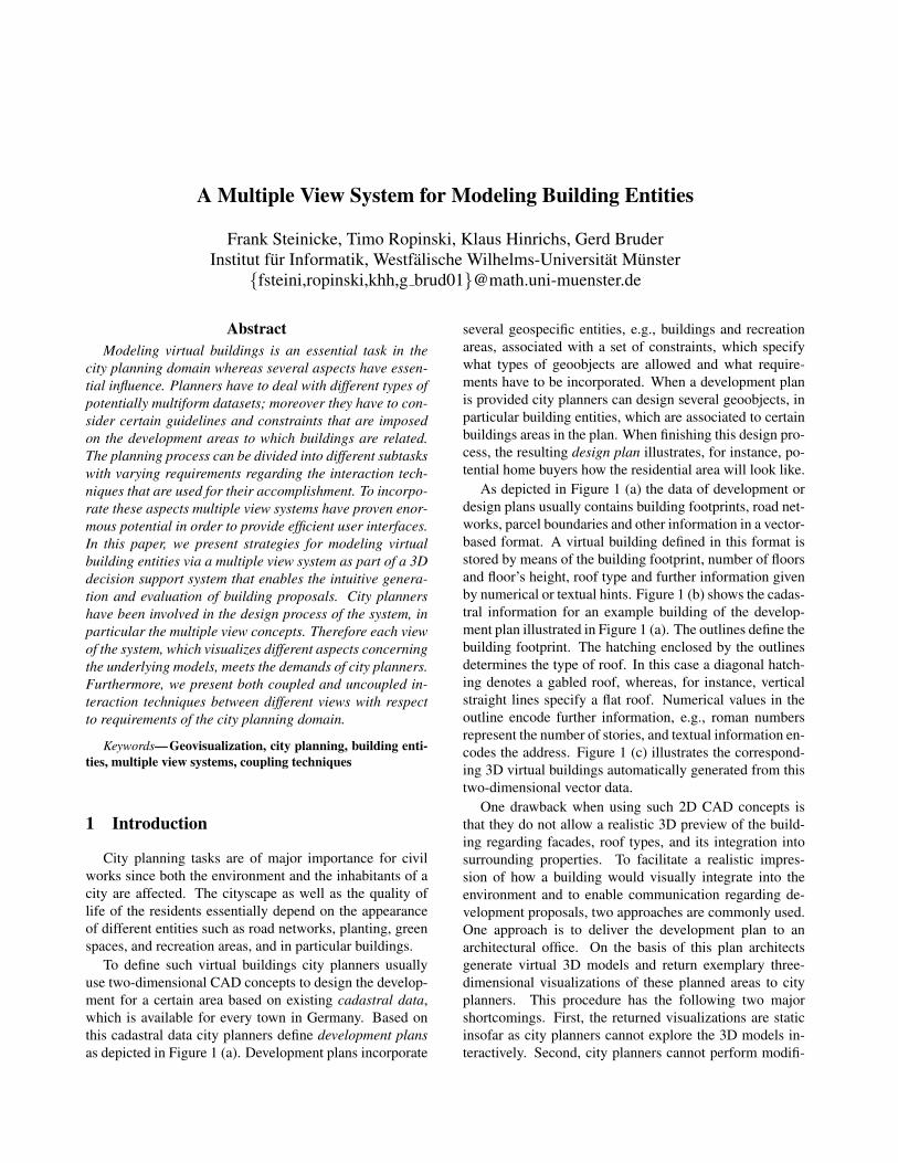
As depicted in Figure 1 (a) the data of development ordesign plans usually contains building footprints, road net-works, parcel boundaries and other information in a vector-based format. A virtual building defined in this format isstored by means of the building footprint, number of floorsand floor’s height, roof type and further information givenby numerical or textual hints. Figure 1 (b) shows the cadas-tral information for an example building of the develop-ment plan illustrated in Figure 1 (a). The outlines define thebuilding footprint. The hatching enclosed by the outlinesdetermines the type of roof. In this case a diagonal hatch-ing denotes a gabled roof, whereas, for instance, verticalstraight lines specify a flat roof. Numerical values in theoutline encode further information, e.g., roman numbersrepresent the number of stories, and textual information en-codes the address. Figure 1 (c) illustrates the correspond-ing 3D virtual buildings automatically generated from thistwo-dimensional vector data.
One drawback when using such 2D CAD concepts isthat they do not allow a realistic 3D preview of the build-ing regarding facades, roof types, and its integration intosurrounding properties. To facilitate a realistic impres-sion of how a building would visually integrate into theenvironment and to enable communication regarding de-velopment proposals, two approaches are commonly used.One approach is to deliver the development plan to anarchitectural office. On the basis of this plan architectsgenerate virtual 3D models and return exemplary three-dimensional visualizations of these planned areas to cityplanners. This procedure has the following two majorshortcomings. First, the returned visualizations are staticinsofar as city planners cannot explore the 3D models in-teractively. Second, city planners cannot perform modifi-
(a) Development data (b) Cadastral data (c) 3D virtual building
Figure 1: Example section of a city development plan embedded into cadastral information (a) and an enlarged view of thecadastral data showing a virtual building (c) and its 3D representation (c).
cations to the 3D models, which, for instance, have beenproposed after reviewing the 3D visualization. Instead,the architectural office has to be asked again to incorpo-rate these modifications into the 3D model. During a plan-ning task, this usually takes several iterations resulting ininefficiency as well as unnecessary expense. The secondcommon alternative to get a realistic impression of a virtualbuilding is to build a physical block model usually made ofwood, plastic or paper. After a physical block model hasbeen finished, performing modifications is often awkward,since most elements are inflexible and fixated to the model,so that they have to be removed and replaced by new ele-ments. For these reasons, simpler solutions to visualizeplanned development areas are desired.
In cooperation with the urban development, city plan-ning and transport planning office as well as the land sur-veying and land registry office of the city of Munster inGermany, we have developed a 3D decision support systemto solve these problems ([16]). This so-called 3D residen-tial city planner enables city planners to generate and eval-uate design plans by means of creating and manipulatinggeoobjects, in particular virtual buildings, and integratingthem into building areas.
We have chosen VRS, the Virtual Rendering System [6],as core graphics library for the 3D residential city plan-ner. VRS is an object-oriented and scenegraph based C++graphics library. It introduces the usage of two differentgraphs. Geometry graphs, which store the visual appear-ance of virtual objects collected in scene nodes, are com-bined with behavior graphs to represent their behavior interms of interaction and animation. Different renderingsare ensured with this library, since VRS provides wrap-ping classes to photorealistic renderers, such as POVRayor Radiance, but also real-time renderers, e.g., OpenGL,
are supported.
The 3D residential city planner consists of four con-ceptual components: The converter tool parses and con-verts the cadastral data into a scenegraph structure, whichis used to represent the corresponding geodata. The geoob-ject model is the collection of geoobjects and their prop-erties. This model is generated during the parser processof the converter tool. Components of this model are build-ings, building and traffic areas, trees etc. The visualiza-tion component constructs the scenegraph representingthe topological structure of the city model. Each scenenode in the geometry graph representing a collection ofgeoobjects is associated with a visual appearance, e.g., byassigning colors or textures. The interaction componentmanages required interactions with virtual 3D city mod-els. A graphical user interface (GUI) based on wxWidgetsallows to access certain interactions.
When using the 3D residential city planner, at first thecadastral data and the development plan are converted intoa three-dimensional representation as illustrated in Figure1 (c). Since the cadastral data is geo-referenced, virtual 3Dcity models can be generated automatically. Because thereis no overall accepted standard for storing cadastral infor-mation, we have developed an interface which providesthe required generality and flexibility to enable import ofcadastral data from different sources. Based on this infor-mation the system generates a geo-referenced virtual 3Dcity model of the surrounding area, which is superimposedwith aerial photographs to provide more realism and higherrecognition. To generate a design plan based on this 3Dmodel, city planners can create or import several geoob-ject entities such as roads, plant and in particular buildingentities.
Generating or manipulating virtual buildings that shall
be integrated into a design plan is a complex task consist-ing of several subtasks. These subtasks make various de-mands on the interaction, since the dimensions and typesof the underlying model vary, and restrictions associatedwith certain development plans are different for each build-ing area. When developing a virtual city model, severalsources with different dimensionality have to be combined.For example, vector-based cadastral data and developmentplans as well as raster-based aerial photographs and tex-tures are two-dimensional, whereas the buildings heightand roof geometry describe three-dimensional structures.Hence, it is beneficial to use different interaction tech-niques to accomplish the tasks to be performed. For ex-ample, manipulations of building footprints are most in-tuitive to perform by changing the vertices in two dimen-sions via drag and drop or by specifying numerical values.In contrast, roof types or integration of virtual buildingsinto surroundings can be evaluated best in three dimen-sions. Furthermore, there are certain restrictions regard-ing the allowed operations, e.g., in certain building areasusually only certain roof types are allowed, or distancesbetween buildings as well as buildings and streets have tobe fulfilled. In addition, to allow a better comprehensionwhen viewing a virtual building different levels of abstrac-tion are required, e.g., city planners desire both photoreal-istic as well as non-photorealistic, e.g., block model, visu-alization for virtual buildings ([3, 7]).
All these different issues and requirements have to beconsidered, when providing an intuitive user interface tosupport the efficient generation of virtual buildings. How-ever, to prevent a contextual switch when city plannersperform building planning tasks incorporating multiformdatasets, different aspects can be combined in multipleview systems ([11, 14, 13]). According to North and Shnei-derman ([11]), multiple view systems are interactive sys-tems, which use two or more distinct views to support theexploration and investigation of conceptual entities. Thiscan be achieved by presenting different aspects of the sameinformation in different views in order to support usersto better understand structures and configurations ([1]).Such multiple view system are commonly used, and theirapplication has emerged as a valuable strategy for manydomains, for example, medical visualization, informationvisualization, architectural design, 3D modeling, or webbrowsing ([13]). For instance, medical visualization appli-cations usually exploit three views providing axial, coro-nal, sagittal slices of an object to be analyzed ([12]). Em-pirical studies of such multiple view systems have pointedout significant advancement in user performance in a vari-ety of these situations.
As mentioned above the concept of multiple view sys-tem is widely used in several application domains. For the
geovisualization domain, in particular city planning, thereare some approaches providing multiple views accordingto the aforementioned different dimensions of the datasets([5, 4]). However, in these systems only a subset of therequired information is presented, e.g., the surrounding ofthe building as well as the underlying restrictions of the de-velopment plan are ignored. Thus, when using these sys-tems the constraints that affect the design process have tobe considered by the city planners using different strate-gies. Therefore, city planners have to use another appli-cation, which shows a digital version of the developmentplan, or a printed version has to be exploited. However, itwould be desirable to combine these aspects in a computeraided design process. To the authors knowledge none ofthe currently available multiple view systems for city plan-ning, in particular modeling of virtual buildings, incorpo-rates the addressed multiform requirements.
In this paper, we present a multiple view system for de-signing virtual buildings that meets the demands of cityplanners. Furthermore, it is shown that multiple view sys-tems provide enormous potential for the domain of cityplanning if appropriate interaction concepts are supported,e.g., both a tight coupling between the views as well asautonomous interaction should be possible. The paper isstructured as follows. Section 2 discusses the demands ofthe city planners with respect to the building modeling pro-cess. Section 3 introduces the building editor and describesthe coupling of multiple views and how interaction is per-formed. Section 4 shows the result of a preliminary us-ability study in which a planning process based on the pro-posed multiple view system is compared with a planningprocess based on the ordinary 2D single view procedure.Section 5 concludes the paper and gives an overview aboutfuture work.
2 Requirements of City Planners
Since multiple view systems provide the potential forefficient user interfaces, their application in 3D residentialcity planning systems to support the intuitive design of vir-tual buildings is desired. However, as described in [2], it isa challenging task to chose an appropriate number and kindof views in order to provide intuitive and comprehensibleinterfaces and not to overstrain the user. Since the urbandevelopment, city planning and transport planning officeas well as the land surveying and land registry office of thecity of Munster in Germany were involved closely into thedevelopment process of the 3D residential city planner, inparticular the multiple view building editor, it has been en-sured that all developed concepts are relevant with respectto the demands of the city planners.
During the design process of the multiple view building
editor the city planners have been involved during the im-portant phases. At first, in cooperation with the city plan-ners we decided to apply multiple views for the computeraided planning of virtual buildings. Following, in a se-lection phase a set of coordinated views to be used wereidentified, and we determined how information has to besegmented to the used views. In the following presentationphase, we specified how the views should be presented.Due to the fact that many different arrangements on thescreen are possible as well as different visualizations in-side each view, we designed proposals of possible visual-izations and arrangements. The city planners tested andevaluated these proposals and gave us feedback and hintswe integrated to obtain an improved version. This proce-dure took several iterations. In the interaction phase we hadto determine, which interactions among the different viewsare possible with respect to the demands of city planners.
The way in which multiple view systems visualize cer-tain aspects of datasets depends on the intention of the viewand the characteristics of the data. Multiple realizationscan be formed from the application of different visualiza-tion algorithms, by changing the mapping algorithm on thedata or by using the same visual form, but rendered fromdifferent positions and orientations ([15]). These aspectsand factors have essential influence on the choice of views,choice of data to displayed in each view, choice of inter-activity provided for each view and its level of couplingbetween the views.
In the following subsections these demands on the de-sign of the building editor, which affected the describedphases, are pointed out.
2.1 Miscellaneous Views
As mentioned in the introduction, one major drawbackof the usage of two-dimensional CAD systems is, that usu-ally only one preview of a building, e.g., orthogonal viewonto the building footprints, is supported. City planners ex-ploit photorealistic 3D previews provided by architecturaloffices, but also schematic representations given by build-ing block models, to obtain a comprehensible impressionof how potential buildings would look like and how theyvisually integrate into the surrounding. Although theserepresentations provide city planners with valuable infor-mation about the appearance of certain buildings, the obvi-ous drawback results from the fact that city planners per-ceive these impressions not during the actual design pro-cess. Hence, city planners desire to have more sophisti-cated control about the 3D previews of building entitiesin order to provide them with additional information andadvanced comprehension especially during the design pro-cess. Thus, interactive exploration supported by intuitivenavigation concepts, which allow to view a building entity
from different perspectives, is a major demand. However,the demand for previews is not restricted to photorealis-tic visualization of virtual buildings, city planners also de-sire different levels of abstraction, i.e., realistic represen-tations but also schematic illustrations provided by non-photorealistic renderings (NPR). Such conceptual viewsenable them to evaluate the modifications applied to a par-ticular building in an abstract way. To assess modificationsin the context of the surrounding of such buildings, i.e.,building areas, other buildings, streets etc., city plannersdesire also contextual previews that provide them with anoverview about the building’s surrounding.
2.2 Modification of Properties
City planners usually use two-dimensional CAD sys-tems in order to change the features of virtual buildingswith respect to their main properties, i.e., building foot-prints and building’s height, in particular the number ofstories and the height of each story as well as the jambwall. When using 2D CAD systems, they define buildingfootprints in 2D and add textual flags indicating further in-formation such as building’s height, roof type etc. Theydesire to be able to specify these and further properties inan intuitive way. Furthermore, city planners request to beable to generate arbitrary complex buildings, for example,with overlapping footprint edges, extra stories built on topof already existing building structures etc. Furthermore,city planners desire flexible roof types for a building. Sev-eral generic roof types need to be supported, e.g., flat roofs,gabled roof, hipped roof etc.
Although change of visual appearance in terms of fa-cades or roof covering etc. is usually not performed by cityplanners, they desire to be able to texture facades by apply-ing brick, wood, plaster or photographic textures; more-over, positions and sizes of doors and windows should bemodifiable in order to enable a more realistic impression.
2.3 Handling of Multiple Data Models
City planning deals with multiple data models from dif-ferent sources that contribute to the generation of virtualcity models. As mentioned before, for example, cadas-tral data and development plans are given in a vector-basedformat, whereas aerial photographs and textures, e.g., forground, roofs or facades are given in raster-based formats.Furthermore, the cadastral data contains several layers;building footprints are stored in one layer, whereas streets,or textual information are provided in other layers. In ad-dition, when generating a design plan, city planners haveto incorporate the underlying terrain model, which affectsthe appearance of the cityscape.
There are many properties of a building, which can be
defined in one dimension, for example, number of stories,a stories height etc. Other features of a building entity suchas building footprints are given by two-dimensional data,whereas a realistic building preview can be provided best inthree dimensions. Besides these typical requirements onhandling multi-dimensional datasets, city planner desire tobe able to evaluate the behavior of shadows cast by build-ings over time giving a forth dimension. Thus, potentialhome buyers may estimate the insolation, for example inorder to set up solar heating or to plan balcony and gardeninstallations.
2.4 Coupled vs. De-Coupled Interaction
Many of the aforementioned requirements argue for theusage of a multiple view system. Once multiple views havebeen generated they may be explored and manipulated si-multaneously; in this case the views are said to be coupled.A tight coupling, sometimes referred to as linking or coor-dination, of the views is important to enable the synchro-nization during interaction processes such that users canrelate information between the views. Furthermore, ele-ments displayed in several views may be jointly selectedin one view, which causes their highlighting in the corre-sponding views ([8]).
Most of the described demands require a tight couplingfor the linkage between the different views, for example,all modifications of the geometry influence the visual ap-pearance of the 3D building preview. However, sometimesit is desired to allow an unconstrained coupling in orderto provide the user with more autonomy when interactingwith a single view of a multiple view system. Some build-ing planning operations can be performed in a de-coupledway, i.e., interactions performed in one view need not af-fect another view. For instance, if an NPR visualization ischosen for the preview, it may be changed for another viewalso, e.g., a lateral view, but it need not. In general, how-ever, most interactions should be cross related to enhancethe navigation process when using a multiple view system([10, 15]). For instance, the selection of a particular wall inorder to change the position of windows or doors is moreeasily performed in a two-dimensional view in comparisonto a selection in a lateral view in which the desired wall isoccluded, for example, by another wall. This is due to thefact that the virtual building has to be rotated first in orderto be able to select the desired wall.
Furthermore, as pointed out by city planners many inter-action concepts require different dimensions. For example,modifications of two-dimensional footprints are more eas-ily accomplished in two dimensions, whereas the selectionof the floor on which the modifications shall be performedis difficult in 2D, since it would require a mechanism to tabthrough the stories. Hence, an active story is more easily
to specify in a lateral view or 3D preview, and thereuponthe footprints are modified in a two-dimensional view.
2.5 Constraint-based Interaction
When developing a virtual building several constraintshave to be incorporated, which influence the interactionwith geoobjects and restrict their manipulability. Theseconstraints classify into geometrical, topological, andstructural constraints. Geometrical constraints restrictinteraction processes referring to the geometry of buildingentities, e.g., only floor-wise scaling is supported, whereasa maximum building height has to be observed. Topo-logical constraints determine relations between buildings.For instance, a development plan can define a minimaldistance between geoobjects, such as distances betweenbuildings or distances between buildings and streets, whichhave to be maintained. City planners can define struc-tural constraints in a development plan, which relate abuilding entity exactly to one building area. Furthermore,the city planner can define further constraints in terms ofthe orientation of building entities or approved roof types.Besides such constraints, there are further dependencies,which have to be incorporated. For example, the buildingsin a certain area must be uniform in terms of their visualappearance.
Although many constraints are defined in developmentplans, city planners desire to be able to suspend theseconstraints. Hence, a mechanism is needed to turn offconstraints during interaction. Nevertheless, city plannerswant to get informed about the constraints and restrictions,which are imposed on certain building areas.
3 Multiple Views for Modeling Buildings
Regarding the requirements discussed in the previoussection, we have developed a multiple view building edi-tor system, which provides city planners with several dis-tinguished views supporting appropriate interaction tech-niques. This section explains this multiple view system indetail; in particular the features of each view as well asthe associated interaction techniques are pointed out. Fur-thermore, the coupled and de-coupled interaction conceptsbetween the different views are discussed.
3.1 View Layout
As illustrated in Figure 2, the proposed multiple viewsystem is composed of six different views. In addition,each window representing a view and its properties is usedas a floating window and can be docked to the multipleview system. Hence, the arrangement of the views and

Figure 2: The building editor is composed of six views: contextual 3D preview (upper-left), 2D vector-based topview(lower-left), lateral view (upper-middle), orthogonal wall view (lower-middle), hierarchical structure view (upper-right),and property view (lower-right).
their sizes are variable; thus they can be adapted in a user-definable way.
When using the multiple view building editor either anexisting building can be loaded into the editor, or a newbuilding can be created, whereas thereupon the building isin the focus of each view. In the upper-left view, referredto as contextual 3D preview, a three-dimensional previewof the virtual building shows its integration into the sur-rounding. The neighbor buildings can be either displayedin order to allow a preview of the integration or they canbe ignored in order to maintain the focus on the build-ing to be manipulated. The vector-based topview in thelower-left view shows a two-dimensional presentation ofthe building footprint, it enables city planners to modifythe ground plans of all buildings’ floors. Moreover, an ar-bitrary wall can be selected and thereupon the selected wall
will be in the focus of the view in the upper-middle viewof the editor, referred to as lateral side view, i.e., the vir-tual camera is steered to that wall in order to afford a sideview. Furthermore, also the orthogonal wall view depictedin the lower-middle view focuses on the current wall. Us-ing that view the city planner can add respectively removeor manipulate windows or doors, and he can assign corre-sponding textures to them. The hierarchical structure viewin the upper-right view allows a visualization of the sto-ries in a hierarchical visualization ordered by stories. Theproperty view in the lower-right shows further informationabout particular parts of the building such as windows orwalls.
After finishing the generation of a virtual building, it canbe stored and imported into a virtual 3D city model. Oncegenerated virtual buildings can be stored in a virtual build-
ing library that can be accessed in each new developmentplan.
3.2 Interaction with Multiple Views
In the next subsections we will explain how certain in-teraction concepts are realized within the views and howthese interactions are coupled respectively de-coupled inorder to provide an efficient user interface.
3.2.1 Contextual 3D Preview
The conceptual 3D preview (see Figure 2 (upper-left)) ofthe editor provides city planners with a three-dimensionalpreview of the building, which shows its integration intothe surrounding. The virtual camera in this preview usesa focus-based approach such that all mouse-based naviga-tion manipulates the virtual camera in a way that the cityplanner can move around the building, he can zoom in andout, whereas the building always stays in the focus of thevirtual camera. The toolbar allows to switch between dif-ferent visualizations, e.g., realistic rendering as shown inFigure 2 (upper-left), NPR visualization as illustrated inFigure 2 (upper-middle) etc. Furthermore, developmentplan information, aerial photographs as well as textures canbe switched off or they can be attached to the 3D model.By default interactions performed in the 3D preview haveno influence on the other previews, i.e., interactions per-formed in this view are de-coupled from the other views.This enables the planner to review the building processwithout affecting the other views where modifications areperformed currently. However, the user can link this viewto other views such that camera motions performed in thisview are also applied to the other views.
3.2.2 Vector-based Topview
The vector-based topview on the lower-left of Figure 2shows the building footprints of each story of a buildingentity. The city planner can modify the position of eachvertex by a simple drag and drop mechanism. The devel-opment plan can overlay the grid such that city plannerscomprehend the restrictions concerning the manipulationprocess. By overlaying the development plan onto thisview, the city planner gets visual information about theconstraints that impose buildings, which are located intothe corresponding parcel boundary area. For example, thetransparent light-colored blue area shows a building area,where the building entity has to be placed in. Furthermore,constraint-based interaction concepts prevent not allowedoperations, e.g., vertices can not be moved outside the par-cel area.
This view is tightly coupled to the other views. Dur-ing modifying the vertices of the building footprints otherviews are updated accordingly. When the city planner se-lects a wall as illustrated for the wall at the upper right, theactive wall is marked in this view and the camera steers au-tomatically to that wall in the lateral view, where it is han-dled as active wall as described in Section 3.2.3. Since asmooth motion of the virtual camera is used for the steeringprocess, the city planner comprehends the relation betweenthese views immediately.
3.2.3 Lateral View
Similar to the contextual 3D preview, the lateral view en-ables a three-dimensional preview of the building entity;in particular it allows an evaluation of a selected wallwithin a certain story. After the city planner has selecteda wall of the building entity, for example via the vector-based topview, the virtual camera initiates a motion pro-cess, which results in a steered view to that wall. To drawthe city planner’s attention to the selected story and the se-lected wall, a frame is displayed around the wall’s edgesand around the entire story’s bounding box. Although ini-tially the camera is focused on one wall, the city plannercan modify the camera in terms of rotation around or lift-ing along the height axis in order to access another wallmanually. The view can be focused to another wall byusing mouse-based picking techniques to select a desiredwall in this view. Further camera modifications are pre-vented in this view in order to prevent an overstraining ofthe city planner resulting from complex exploration tech-niques. The visualization can be altered in the same wayas for the contextual 3D preview. A wall in the focus ofthis 3D lateral view will also be loaded into the orthogonalwall view, described in the next subsection.
3.2.4 Orthogonal Wall View
The orthogonal wall view is tightly coupled to the vector-based topview as well as to the lateral view described in theprevious subsections. The active wall in the focus of thelateral view is displayed as two-dimensional facet into thisview. The city planner can associate textures to this wall,e.g., to change the construction material such as bricks,wood or plaster. Moreover, he can arrange windows anddoors by clamping them onto the wall by means of us-ing direct interaction strategies with the mouse. The visualmodifications performed in this window are transferred tothe 3D preview as well as to the lateral view, which resultsin tight coupling.
3.2.5 Hierarchical Structure View
This structured view at the upper-right of the multiple viewsystem visualizes the building entity, in particular its sto-ries, in a textual hierarchical structure; the order is definedby the stories. This view is primarily used to add respec-tively remove further stories, or to access them in corre-sponding other views. For example, if the city planner se-lects a story within this structure, the story will also be inthe focus of the lateral view as well as the vector-basedtopview and the orthogonal wall view.
3.2.6 Property View
The property view enables the city planner to associatetextual or numerical values to each entity of a building.Thereby, city planners can determine the height of a storyor they can assign house numbers or comments to a build-ing, which can be used, for example, for annotation pur-poses. Furthermore, all values definable via the previouslydescribed views can be entered in a discrete way in orderto support exact inputs, e.g., to specify the vertex positionsof the building footprints in Gauß=Kruger coordinates.
4 Preliminary Usability Study
Our cooperation partners, in particular the land survey-ing and land registry office, have evaluated a pre-versionof the proposed building editor concepts. As the versionintroduced in this paper, the pre-version was also based onmultiple view system strategies. However, it lacked manyfeatures that are supported by the current version. Manyof these functionalities have been integrated during and af-ter the evaluation phase of the cooperation partners. Thesefunctions include snapping processes when modifying thevertices of the building footprints and the support of over-laying this 2D data with a development plan to incorporateconstraints imposed by the development plan. In addition,visualization techniques that enable different levels of ab-straction that are specifiable for each preview have beenintegrated.
Hence, we have tested the current version proposed inthis paper in a further usability study in which 8 users haveparticipated. The 7 male and 1 female participants arestudents of geoinformatics (1) and computer science (4)as well as research assistants (2), which are familiar withcity planning tasks. In this preliminary usability study theobjective was to evaluate whether and how users exploitmultiple views when generating a virtual building. Weprovided the participants with a standard desktop environ-ment, i.e., 19” display in combination with a 2D mouse anda keyboard. In the next both subsection we propose the testsetup and the results of this user study.
4.1 Task
We provided the participants with a test environment inwhich they had to rebuild simple virtual buildings such asillustrated in Figure 1 (c), whereas the degree of complex-ity varied for each building. The buildings were classi-fied into simple and into complex buildings with respectto the number of vertices per story as well as the numberof floors, i.e., a building consisting of at least two floorsand with at least six vertices that define the footprints ofthe first floor is classified as a complex building, whereasa building with equal or less number of floors respectivelyvertices is classified as simple building.
Based upon three dimensional visualizations that illus-trate the target building entities from different views, theparticipants had to generate the corresponding buildingboth using a two-dimensional CAD system as well as usingour proposed multiple view building editor system. Thevisualizations of the 3D target buildings were availableto the participants during the entire building process. Ascreen capturing software recorded the proceedings of theusers. Thus, a review to analyze the generation processeshas been possible.
We have evaluated the accuracy of reproduced build-ings in terms of equality with the target building and wehave measured the required time using both systems, i.e.,2D CAD and the proposed multiple view system. Further-more, we have measured the time and number of relevantactions performed in each subview.
Since the task was simplified to the reproduction of agiven virtual building, neither aesthetic nor design taskshad to be accomplished by the participants, which woulddefinitely benefit from 3D previews. Furthermore, no con-straints regarding neighborhood information or constraintsimposed by the development plan had to be consideredby the users. Hence, in the tested planning environmentthere was no need for a multiple view system, i.e., all taskscould be accomplished in 2D very efficiently. However,we wanted to evaluate whether and how the adding of thedescribed views affects such tasks typically performed in2D.
4.2 Results
The main result of the user study indicates that withan increasing complexity of the target buildings the us-age of multiple views gets more beneficial, although thetasks were constrained to a simple reproduction of a givenbuilding. However, the study pointed out that the requiredtime to perform the generation process was less using or-dinary 2D CAD approaches. As illustrated in Figure 3 therequired time to reproduce a simple building averages to167 seconds when using a 2D system in comparison to 215
0
50
100
150
200
250
300
simple buildings complex buildings
2D CAD Multiple View System2D CAD Multiple View System
(1) (2) (3) (4)
time
in se
cond
s
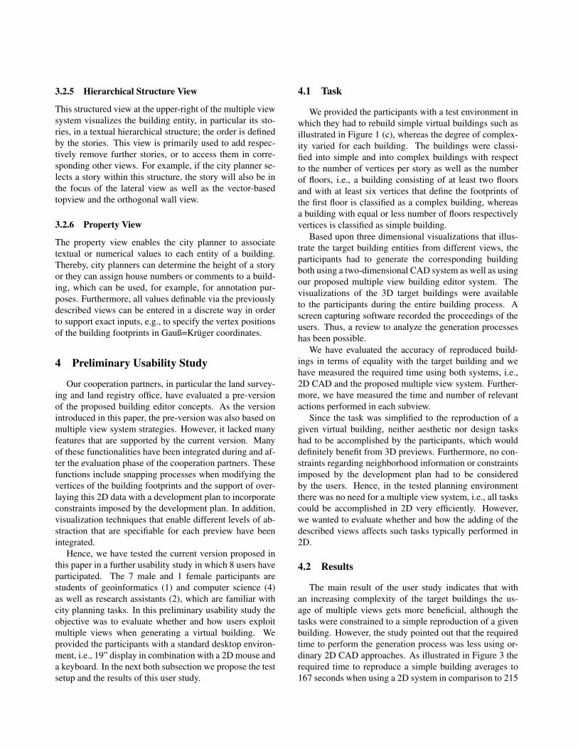
Figure 3: Required time for the generation of simple buildings using the 2D CAD system (1) respectively the proposedmultiple view system (2) and for the generation of complex buildings using 2D CAD concepts (3) respectively the multipleview system (4).
seconds when using the multiple view system. For morecomplex buildings the required time to perform the gener-ation task averages to 202 seconds when using 2D CADstrategies, whereas when using the proposed multiple viewsystem the task requires 236 seconds in average.
Based on observations of the participants during thetest, this is due to the fact that when using the 2D view only,the users seem to be more focussed on the objective. Whenthe participants use a straightforward way, for example, bysuccessively handling the building walls and floors to ar-range windows and doors, without considering the result,this task can be accomplished very fast in particular in twodimensions. However, this procedure causes errors sincethe spatial cognition of a 3D representation of the targetbuilding to a 2D topview is more difficult than comparingtwo visual representations defined with the same dimen-sionality. When additional 3D previews are provided theimmediate visual feedback attracts the users attention andthe user checks performed steps before proceeding
Hence, the usage of additional 3D preview results in ahigher accuracy when accomplishing certain tasks. Thisissue is also reflected in the user study. When using themultiple view system, each generated building was builtcorrectly in terms of building footprints, position of wallsand doors, number of stories and roof types etc. In con-trast, the participants made faults when using only the 2DCAD system, i.e., one users chooses the wrong roof type,two users misarranged doors and windows to the walls.
Furthermore, Figure 3 indicates that with an increasingcomplexity of the target building the performance loss re-sulting from the usage of multiple view system decreases.While for simple buildings the performance loss when us-ing a multiple view system is more than 22%, the per-formance loss decrease to less than 15% when generating
more complex buildings; although the difference betweenboth types of buildings was marginal, e.g., specifying thebuilding footprints of the complex buildings requires onlytwo further vertices. Therefore, we assume that for morecomplicated buildings, which, for example, consist of sev-eral stories with complex polygonal footprints, the usage ofthe proposed multiple view system will increase the perfor-mance. Moreover, in particular design tasks, which havebeen ignored in this user study, benefit from the usage ofmultiple view systems because the user gets immediate vi-sual feedback by means of 3D previews. Hence, an exten-sion of the described usability study that incorporates suchissues will underline further advantageous of the proposedsystem.
5 Conclusions and Future Directions
In this paper we presented a multiple view system forthe generation and manipulation of virtual buildings. Theusage of the described coupled as well as de-coupled inter-action concepts has shown the potential for the city plan-ning domain. Preliminary tests have indicated that themodeling process of building entities can be performedmore accurately and therefore more efficient in compari-son to the usage of ordinary 2D procedures. However, forsimple building entities ordinary 2D CAD systems seem tobe more advantageous.
Currently, the land surveying and land registry officeevaluate the proposed version of the multiple view build-ing editor system and the urban development, city planningand transport planning office will test the application in areal planning process soon. When these field studies arefinished, modifications of the current system and integra-
tion of further functionality will be accomplished. Amongothers these functions will include an automatic featureextraction from images used for texturing walls. For ex-ample, from images, which have been taken with a digitalcamera, windows and doors shall be extracted in order togenerate according geometry that can be modified there-upon. Furthermore, we plan to perform another usabilitystudy in which also design aspects and constraints imposedby development plans have to be incorporated.
Acknowledgments
We would like to acknowledge the land surveying andland registry office as well as the urban development,city planning and transport planning office of the city ofMunster for their cooperation and useful hints during thedesign and implementation phase of the 3D decision sup-port system, in particular the multiple view system. Fur-thermore, we thank both cooperation partners for the pro-vision of relevant datasets.
We also would like to thank the students who imple-mented most parts of the 3D residential city planner aswell as the multiple view system and we thank the partic-ipants of the user study. Moreover, we acknowledge JorgMensmann for recording a demonstration movie ([9]).
References[1] M. Baldonado, A. Woodruff, and A. Kuchinsky.
Guidelines for Using Multiple Views in InformationVisualization. In Proceedings of the Working Confer-ence on Advanced Visual Interfaces, pages 110–119,2000.
[2] N. Boukhelifa, J. Roberts, and P. Rodgers. A Co-ordination Model for Exploratory Multi-View Visu-alization. In J. Roberts, editor, Proceedings of theInternational Conference on Coordinated and Multi-ple Views in Exploratory Visualization (CMV 2003).IEEE, 2003.
[3] H. Buchholz, J. Dollner, M. Nienhaus, and F. Kirsch.Real-Time Non-Photorealistic Rendering of 3D CityModels. In Proceedings of the 1st InternationalWorkshop on Next Generation 3D City Models, 2005.
[4] J. Dollner and H. Buchholz. Continuous Level-of-Detail Modeling of Buildings in Virtual 3D CityModels. In Proceedings of the 13th InternationalSymposium of Geographical Information Systems(GIS), pages 173–181. ACM, 2005.
[5] J. Dollner, H. Buchholz, F. Brodersen, T. Glander,S. Jutterschenke, and A. Klimetschek. SmartBuild-ings - A Concept for Ad-Hoc Creation and Refine-ment of 3D Building Models. In Proceedings of the
1st International Workshop on Next Generation 3DCity Models, 2005.
[6] J. Dollner and K. Hinrichs. A Generic Rendering Sys-tem. IEEE Transaction on Visualization and Com-puter Graphics, 8(2):99–118, 2002.
[7] J. Dollner and M. Walther. Real-Time ExpressiveRendering of City Models. In Proceedings of 7th In-ternational Conference on Information Visualization,pages 245–250. IEEE, 2003.
[8] A. Martin and M. Ward. High Dimensional Brushingfor Interactive Exploration of Multivariate Data. InIn Proceedings of Conference on Visualisation, pages271–278. IEEE, 1995.
[9] J. Mensmann. Multiple View Building Edi-tor System, Video Presentation (available underhttp://3dsp.uni-muenster.de).
[10] C. North. Multiple Views and Tight Coupling in Vi-sualization: A Language, Taxonomy, and System. InProceedings of CSREA CISST, Workshop of Funda-mental Issues in Visualization, pages 626–632, 2001.
[11] C. North and B. Shneiderman. A Taxonomy of Mul-tiple Window Coordinations. Technical Report CS-TR-3854, University of Maryland Computer, 1997.
[12] C. North, B. Shneiderman, and C. Plaisant. User Con-trolled Overviews of an Image Library: A Case Studyof the Visible Human. In Proceedings of ACM Dig-ital Libraries, Reprinted in Readings in InformationVisualization: Using Vision to Think, pages 74–82.Morgan Kaufmann Pub, 1999.
[13] J. C. Roberts. Aspects of Abstraction in ScientificVisualization. PhD thesis, Computing Laboratory,1995.
[14] J. C. Roberts. On Encouraging Multiple Views forVisualization. In E. Banissi, F. Khosrowshahi, andM. Sarfraz, editors, Proceedings International Con-ference on Information Visualization, pages 8–14.IEEE, 1998.
[15] J. C. Roberts. Multiple-View and Multiform Visual-ization. Proceedings of Visual Data Exploration andAnalysis, 3960(VII):176–185, 2000.
[16] F. Steinicke, T. Ropinski, K. Hinrichs, andJ. Mensmann. Urban City Planning in Semi-immersive Virtual Reality. In Proceedings of the In-ternational Conference on Computer Graphics The-ory and Applications (GRAPP2006), pages 192–199,2006.


![Emergency Communication Guide for Public Entities [in Hebrew]](https://static.fdokumen.com/doc/165x107/631bd186665120b3330b8d32/emergency-communication-guide-for-public-entities-in-hebrew.jpg)

