FM6-135(1969).pdf - Berlin Information-center for ...
84
JJS" s/sfwir 40. Í ' FM 6-Î35% \ DEPARTMENT OF THE ARMY FIELD MANUAL 7« y- ADJUSTMENT OF ARTILLERY, FIRE THE COMBAT SOLDIER THE A1MY LIBRARY WASKiriilOW, D. C. EADQUARTERS, DEPARTMENT OF THE ARMy FEBRUARY 1969 TACO 6677C
-
Upload
khangminh22 -
Category
Documents
-
view
0 -
download
0
Transcript of FM6-135(1969).pdf - Berlin Information-center for ...
J JS" s/sfwir 40. Í
' FM 6-Î35% \ DEPARTMENT OF THE ARMY FIELD MANUAL 7« y-
ADJUSTMENT
OF
ARTILLERY, FIRE
THE COMBAT SOLDIER THE A1MY LIBRARY WASKiriilOW, D. C.
EADQUARTERS, DEPARTMENT OF THE ARMy
FEBRUARY 1969
TACO 6677C

FIELD MANUAL
FM 6-135
HEADQUARTERS
DEPARTMENT OF THE ARMY
WASHINGTON, D.C. H February 1969 No. 6-135
ADJUSTMENT OF ARTILLERY FIRE
BY THE COMBAT SOLDIER
Paragraphs
CHAPTER 1. GENERAL 1-5
2. CONDUCT OF FIRE
Section I. General 6-13
II. Requesting fire - - . 14-25
III. Area fire - 26-30
IV. Summary of principles 31, 32
V. Suggestions for special situations 33-35
VI. Observation 36-39
VII. Communications 40-42
APPENDIX A. REFERENCES
B. HINTS FOR THE OBSERVER
INDEX
/ ’'This manual supersedes FM 6-135, 9 January 1963.
Page 3
8
24
39
50
51
53
61
67
69
71
AGO 6677C 1

CHAPTER 1
GENERAL
1. Purpose and Scope
This manual provides basic instruction in the technique of adjusting field artillery fire, includ- ing the cöfiduct of area fire, the principles of ob- servation, and the data transmitted in request- ing artillery fire. It is written for the combat soldier who is not an artilleryman but who may find himself in a position from which he can observe and adjust artillery fire on an enemy. The material presented herein is applicable with- out modification to both nuclear and nonnuclear warfare.
2. Changes or Comments
Users of this manual are encouraged to submit recommended changes or comments to improve the manual. Comments should be keyed to the specific page, paragraph, and line of the text in which the change is recommended. Reasons should be provided for each comment to insure understanding and complete evaluation. Com- ments should be forwarded direct to Command- ant, ATTN : AKPSIAS-PL, U.S. Army Artillery and Missile School, Fort Sill, Oklahoma 73503.
3. Obtaining Artillery Fire a. General. A field artillery observer will not
AGO 6677G 3
always be present when a profitable target ap- pears; hence, each combat soldier must be pre- pared to call for and adjust artillery fire. He requires only the necessary communications and a knowledge of the basic information contained in this manual.
b. Appropriate Artillery Targets. Judgment must be used in the selection of artillery targets. If other weapons are available that are more suit- able under the conditions, they should be used instead of artillery. For example, if an observer sees an enemy patrol of only two or three men within rifle or machinegun range, he should utilize small-arms or automatic weapons fire. However, if he sees a company of enemy infantry or an enemy machinegun, he should call for ar- tillery fire. Resupply of ammunition also is an important factor in deciding which weapon to use. A rifle bullet weighs less than an ounce, whereas an artillery shell weighs many pounds. Some examples of appropriate artillery targets are listed below. The size and disposition of a target and the number of personnel or units of materiel should be included in the call for fire.
(1) Troops in foxholes or dug-in.
(2) Machineguns, especially when they have overhead cover.
(3) Artillery pieces, heavy weapons, mor- tars, and tanks.
(4) Concrete emplacements. (5) Truck and tank columns. (6) Truck parks.
4 AGO 6677C
(7) Troop assembly areas, command posts, and communication centers.
(8) Supply or ammunition dumps.
Note. Minefields and barbed wire entanglements are not included in this list of targets because of the ineffec- tiveness of artillery fire on them.
c. Communications. The combat soldier desir- ing to adjust artillery fire may contact the ar- tillery fire direction center by radio or telephone through the artillery forward observe or liaison officer with his unit or through the communica- tion channels of his own unit for artillery fire (para 40). For methods of requesting fire, see paragraphs 14 through 25.
4. Basic Technical Knowledge
The combat soldier will find that much of his previous training and experience will be of great value in the adjustment of artillery fire. It is not necessary to be a trained forward observer or an expert in communications in order to observe and adjust field artillery fire. However, the ad- justment of artillery fire is greatly facilitated by a knowledge of the methods of conducting fire, the communication nets available, and the proper radiotelephone communication procedures. Every soldier receives training in the following mili- tary subjects, which provide sufficient back- ground to undertake the adjustment of artillery fire by using the procedure described in this manual :
a. Communications.
AGO 6677C 5
b. Map reading, terrain appreciation, and small-unit tactics.
c. Range estimation.
d. Use of binoculars.
e. Phonetic alphabet.
f. Use of compass.
5. Field Artillery Gunnery Team
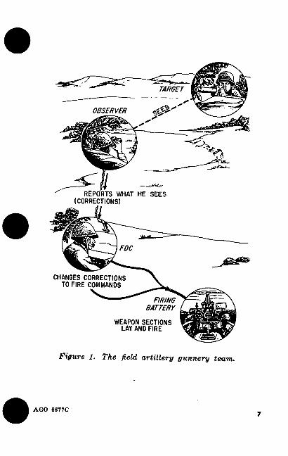
a. General. When a combat soldier adjusts field artillery fire on a target, he becomes a member of the field artillery gunnery team (fig. 1), consist- ing of himself, as the observer; an artillery fire direction center (FDC) ; and a firing battery. The observer spots the projectile bursts with re- spect to the target. He changes these spottings into corrections for deviation (right or left) and range (add or drop) to bring the shell bursts closer to the target.
b. Fire Direction Center (FDC). Personnel in the field artillery fire direction center receive corrections from the observer, change the correc- tions to fire commands, and then relay the fire commands to the weapon crews. If an observer becomes confused or forgets the steps in adjust- ing fire, he can ask the fire direction center per- sonnel for assistance. If necessary, the fire direc- tion center can coach the observer through the adjustment, step by step, and bring fire upon the target.
6 AGO 6677C
OBSERVER
«ri
REPORTS WHAT HE SEES (CORRECTIONS)
EDO
FIRING BATTERY
CHANGES CORRECTIONS TO FIRE COMMANDS
WEAPON SECTIONS LAY AND FIRE
Figure 1. The field artillery gunnery team.
AGO 6677C 7
CHAPTER 2
CONDUCT OF FIRE
Section I. GENERAL
6. Introduction
The purpose of the conduct of fire is to place effective fire on the target by adjusting the fire with data derived from bursts previously ob- served. The fire can be considered as being ad- justed on the target when rounds or fragments strike the target or when the target has been inclosed by a bracket (para 13) of the appropri- ate size.
7. Terminology
a. Certain standard terms are used in the field artillery to simplify calls for fire and radiotele- phone procedures. The terms are defined in FM 6-40. The use of these terms is not in any way intended to keep the observer from transmitting other information which would assist the fire direction center personnel in bringing effective fire to bear on the target.
b. The terms most commonly used in request- ing and adjusting artillery fire are defined as follows :
(1) ADD—A correction used by a spotter or an observer to indicate that an increase in range along a spotting line is desired.
8 AGO 6677C

(2) ADJUST FIRE—1. A command or re- quest to initiate the process of adjustment.
2. A method of con- trol transmitted in the call for fire by the spotter or observer to indicate that he will control the adjustment.
(3) ADJUSTMENT—Process used in ar- tillery fire to obtain correct direction and range in engaging a target by observed fire.
(4) AT MY COMMAND—The command used when it is desired to control the exact time of delivery of fire.
(5) BRACKETING—A method of adjust- ing fire in which a bracket is established by ob- taining an over and short along the spotting line and then successively splitting the bracket until a target hit or desired bracket is obtained.
(6) CALL FOR FIRE—A request for fire containing data necessary for obtaining the re- quired fire on a target.
(7) CANCEL—A command used to cancel a previous order (except for quantity or type of ammunition). The command CANCEL must be followed by announcing the element to be can- celed.
(8) CHECK FIRING—A command to cause a temporary halt in firing.
(9) COORDINATES—Numbers and/or let- ters of a coordinate system which designate a location on a gridded map, photograph, or chart.
(10) CORRECTION—1. Any change in fir- ing data to bring the mean point of impact or burst closer to the target.
AGO 6677C 9
2. A communication proword to indicate that an error in data has been announced and that corrected data will follow.
(11) DANGER CLOSE—Information in a call for fire to indicate that friendly forces may be endangered. This information is always given when friendly forces are within 600 meters of the target.
(12) DESCRIPTION OF TARGET—An ele- ment in the call for fire in which the spotter or observer describes (in terms of number of per- sonnel or units of materiel, size, and disposition) the installation, personnel, equipment, or activity to be taken under fire.
(13) DESTRUCTION FIRE—Fire delivered for the sole purpose of destroying materiel ob- jects.
(14) DIRECTION—Term used by a spotter or an observer in a call for fire to indicate the azimuth of the spotting line. The direction re- ported is always from the observer to the target.
(15) DROP—A correction used by a spotter or an observer to indicate that a decrease in range along a spotting line is desired.
(16) END OF MISSION—A command given to terminate firing on a specific target.
(17) FINAL PROTECTIVE FIRE (FPF)— An immediately available prearranged barrier of fire designed to impede enemy movement across defensive lines or areas.
(18) FIRE FOR EFFECT—1. Fire which is delivered after the mean point of impact or burst
10 AGO 6677C
is within the desired distance of the target or adjusting point.
2. A term which indicates that the adjustment is satisfactory and that fire for effect is desired.
(19) FIRE MISSION—1. Specific assign- ment given to a fire unit as part of a definite plan.
2. Command used to alert personnel of the weapon/battery area and to indicate that the message following is a call for fire. ,
(20) GRID—1. (A short form of the term “military grid.”) The two sets of parallel lines intersecting at right angles and forming squares ; the grid is superimposed on maps, charts, and other similar representations of the earth’s sur- face in an accurate and consistent manner to permit identification of ground locations with respect to other locations and computation of di- rection and distance to other points.
2. (A short form of the term “grid coordinates.”) Used in announcing the lo- cation of a geographic point.
(21) LOST—A spotting or an observation used by a spotter or an observer to indicate that rounds fired by a gun were not observed.
(22) MARK—A call for fire on a specified location to orient the spotter or observer.
(23) OBSERVER IDENTIFICATION—The first element of a call for fire to establish commu- nications and to identify the spotter or observer.
(24) OT DISTANCE, or OT RANGE (see
AGO 6677C 11
para 10)—The distance along an imaginary straight line from the spotter or observer to the target.
(25) OBSERVER-TARGET LINE (OT LINE)—An imaginary straight line from the spotter or observer to the target. See also SPOT- TING LINE.
(26) REFERENCE LINE—A convenient and readily identifiable line used by the spotter or observer as the line to which spottings will be related. See also SPOTTING LINE.
(27) REFERENCE POINT—A prominent, easily located point on the terrain.
(28) REPEAT—A command or request to fire again the same number of rounds with the same method of fire.
(29) ROUNDS COMPLETE—The term used to report that the number of rounds specified has been fired.
(30) SHOT—A report that indicates that a gun or guns have been fired.
(31) SPOT—To determine, by observation, deviations of fire from the target for thé purpose of supplying necessary information for adjust- ment of fire.
(32) SPOTTING—A process of determining, by visual or electronic observation, deviations of artillery or naval gunfire from the target in rela- tion to a spotting line for the purpose of supply- ing necessary information for the adjustment or analysis of fire.
(33) SPOTTING LINE—The gun-target
12 AGO 6677C
line, the observer-target line, or a reference line used by the spotter or observer in making spot corrections.
(34) TARGET—1. Personnel, materiel, or a piece of terrain that warrants engagement by fire and that may be numbered for future ref- erence.
2. An observation indicat- ing that the round hit the target.
(35) TARGET OF OPPOTUNITY—A tar- get visible to a surface or air observer which is within range of available weapons and against which fire has not been scheduled or requested.
(36) TIME ON TARGET (TOT)—The method of firing on a target in which various artillery units time their fire so as to insure that all projectiles reach the target simultaneously.
8. Mil Relation
a. The mil (pf) is the unit of angular measure- ment used in solving the few computations used in the adjustment of indirect fire. A circle is divided into 6,400 angles of 1 mil each. At a distance of 1,000 meters, an object 1 meter wide will measure 1 mil. Thus, mils can be changed to meters by multiplying the number of mils by the range (distance) in thousands of meters. By a similar method, the unknown width of an object or the unknown range to an object may be ob- tained (fig. 2). For example, an object seen at a distance of 2,000 meters is measured with binocu- lars to be 3 mils wide; 3 mils multiplied by 2, the range (distance) in thousands, equals 6
AGO 6677C 13
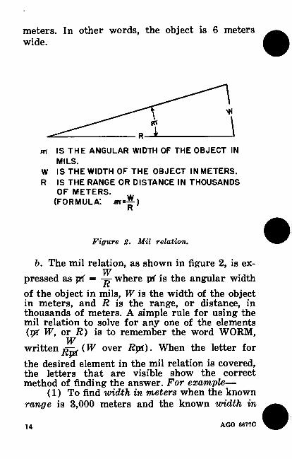
meters. In other words, the object is 6 meters wide.
m IS THE ANGULAR WIDTH OF THE OBJECT IN
W IS THE WIDTH OF THE OBJECT IN METERS. R IS THE RANGE OR DISTANCE IN THOUSANDS
OF METERS. (FORMULA: *i=^)
R
b. The mil relation, as shown in figure 2, is ex- W pressed as pi = -p where pf is the angular width
of the object in mils, W is the width of the object in meters, and R is the range, or distance, in thousands of meters. A simple rule for using the mil relation to solve for any one of the elements (nff VF, or Ä) is to remember the word WORM,
W written ( W over Rpl). When the letter for
the desired element in the mil relation is covered, the letters that are visible show the correct method of finding the answer. For example—
(1) To find width in meters when the known range is 3,000 meters and the known width in
\ MILS.
Figure 2. Mil relation.
14 AGO 6677C
mils is 20 mils, multiply the range in thousands (3) by the width in mils (20) to obtain a width of 60 meters (3 x 20 = 60).
(2) To find range when the known width in meters (between two bursts or two objects) is 60 meters and the known width in mils is 20 mils, divide the width in meters (60) by the width in mils (20) to obtain a range of 3,000 meters (60 + 20 = 3, or 3,000 meters).
(3) To find width in mils when the known width in meters (between a reference point and the target) is 60 meters and the known range to the target is 3,000 meters, divide the width in meters (60) by the range in thousands (3) to obtain a width of 20 mils (60 + 3 = 20).
c. The observer uses the mil relation in com- puting deviation shifts as indicated in figure 3.
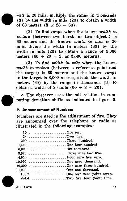
9. Announcement of Numbers
Numbers are used in the adjustment of fire. They are announced over the telephone or radio as illustrated in the following examples:
10 One zero. 25 Two five.
300 Three hundred. 1,400 One four hundred. 6,000 .. Six thousand. 3,925 Three nine two five. 4,050 - Four zero five zero.
10.000 One zero thousand. 10,300 One zero three hundred. 11.000 One one thousand.
100.7 One zero zero point seven. 254.4 Two five four point four.
AGO 6677C 15
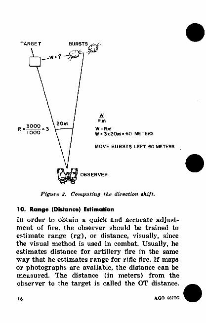
TARGET
'H-?
20iri
R=¿222=3 IOOO
BURSTS^
W RM
W = RM W = 3x20m = 60 METERS
MOVE BURSTS LEFT 60 METERS
OBSERVER
Figure S. Computing the direction shift.
10. Range (Distance) Estimation
In order to obtain a quick and accurate adjust- ment of fire, the observer should be trained to estimate range (rg), or distance, visually, since the visual method is used in combat. Usually, he estimates distance for artillery fire in the same way that he estimates range for rifle fire. If maps or photographs are available, the distance can be measured. The distance (in meters) from the observer to the target is called the OT distance.
16 AGO 6677C
11. Lateral Distance Estimation
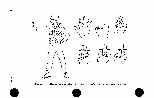
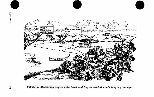
The observer must be able to determine quickly and with reasonable accuracy the shift in meters from an object, registration point, or reference point to a target (fig. 5). He can use an angle- measuring instrument, such as binoculars, to measure the angular distance in mils, or he can use his hand and fingers, held at arm’s length (fig. 4), to measure the angle. Each time the ob- server uses the hand method, he must extend his hand and fingers the same distance from his eye. Each individual, before going into the field, should determine the various measurements of his own hand (fig. 4) and practice measuring angles with his hand. After getting a measure- ment in mils by either of the two methods, the observer uses the mil relation, W = R + jti, to obtain the width in meters between the object or bursts and the target.
12. Spottings
a. Factors Influencing Spottings. The average soldier firing a rifle would be disappointed if he did not have a small, compact group of hits after firing a clip of ammunition at a target. It is not possible to obtain this compactness of hits with an artillery piece. Since each round is affected by varying conditions of weather and by variations in the manufacture of the ammunition and weap- on, several rounds fired at the same range will not strike in the same place. Because projectiles burst and cover a wide area with steel frag- ments, a direct hit on the target is not always
AGO 6677C 17
AG
O 6677C
125 LU
180
n 70 0<- 100
Figure 4. Measuring angles in terms of mils with hand and figures.
ÎÇ- JütreBEHCE^HT
>,«■ 'Hr.. TARGET CONCEALED
X
IOúe*¿*
RANGE 2£00
Figure 5. Measuring angles with hand and fingere held at arm’s length from eye.
essential. The closer the burst is to the target, the denser the fragments that cover the target, and, thus, the greater the number of casualties.
b. Deviation Spottings. An imaginary line from the observer to the target is called the OT (observer-target) line, or spotting line. The bursts of rounds are spotted for deviation as right or left (of the OT line) or as line (on the OT line). The spotting must be measured from the center of the burst or from the center of the group of bursts. All spottings for deviation to the right (left) of the OT line are spotted (so much) RIGHT(LEFT) and are measured in mils. For example, 40 RIGHT would mean that the ob- server saw and spotted the burst 40 mils to the right of the OT line.
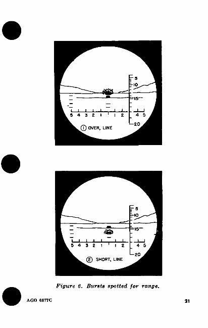
c. Range Spottings. To spot the burst with respect to a target, the observer mentally notes what he sees at the moment the shell bursts. The observer must make his spotting promptly. If the burst is directly behind the target, the observer spots the burst as OVER, LINE (fig. 6). If the burst appears between the target and the observer, he spots the burst as SHORT, LINE (fig. 6). If the observer is not sure whether the burst is over or short of a target, he spots it as DOUBTFUL (fig. 6). A burst not seen by the observer is spotted as LOST. A spotting of LOST, OVER (LOST, SHORT) may be made when the observer has accurate knowledge of the terrain. Sometimes it may be possible to spot a seemingly doubtful round by watching the drifting smoke and dust. The observer, however, must be careful
20 AGO 6677C
r 3 -io
m =15
1 j I I I 1 4 5 5 4 3 Z I
-20 ® OVER, LINE
r 3 HO
20
© SHORT LINE
Figure 6. Bursts spotted for range.
AGO 6677C 21
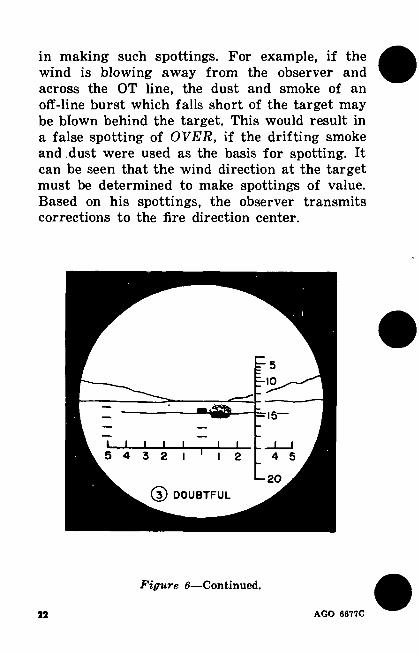
in making such spottings. For example, if the wind is blowing away from the observer and across the OT line, the dust and smoke of an off-line burst which falls short of the target may be blown behind the target. This would result in a false spotting of OVER, if the drifting smoke and . dust were used as the basis for spotting. It can be seen that the wind direction at the target must be determined to make spottings of value. Based on his spottings, the observer transmits corrections to the fire direction center.
15—
4 5
20
(D DOUBTFUL
Figure 6—Continued.
22 AGO 6677C
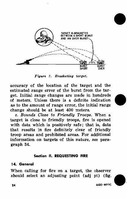
13. Bracketing
a. General. The basic principle in adjusting artillery fire is to bracket the target. Bracketing means to enclose the target between bursts which are over and short of the target in range (fig. 7). For example, if a round bursts on the OT line between the observer and the target and the next round is fired at a 400-meter greater range and bursts on the OT line beyond the target, the target is bracketed between these two ranges. The observer knows that the target liés some- where within the 400-meter bracket. This bracket is split by dividing it in half. To split the bracket, the observer sends a correction of DROP 200. Whether the spotting of the next round fired is short (fig. 6) or over (fig. 6), the observer will know that the target now lies within a 200-meter bracket. Assuming that the round that split the 400-meter bracket was short, he announces a cor- rection of ADD 100. At this point the bracket has been narrowed to 100 meters. If the next round fired results in a spotting of over (fig. 6) or short (fig. 6), the observer has established that the target is within a 100-meter bracket and has completed the adjustment. A bracket of 100 meters is considered appropriate for most targets, and fire for effect (para 29 and 32) is started by splitting the 100-meter bracket.
h. Range Bounds. After a round has been spotted, the first range correction sent to the fire direction center should be large enough to bracket the target. To obtain this bracket, the observer bases the size of the first range bound on the
AGO 6677C 23
TARGET IS BRACKETED BETWEEN A SHORT BURST AND AN OVER BURST-. A
BURST SHORT
BURST OVER
Figure 7. Bracketing target.
accuracy of the location of the target and the estimated range error of the burst from the tar- get. Initial range changes are made in hundreds of meters. Unless there is a definite indication as to the amount of range error, the initial range change should be at least 400 meters.
c. Bounds Close to Friendly Troops. When a target is close to friendly troops, fire is opened with data which is positively safe; that is, data that results in fire definitely clear of friendly troop areas and prohibited areas. For additional information on targets of this nature, see para- graph 34.
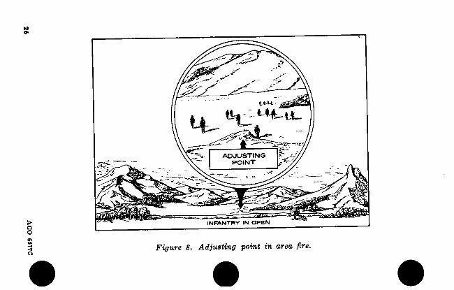
14. General
When calling for fire on a target, the observer should select an adjusting point (adj pt) (fig.
Section II. REQUESTING FIRE
24 AGO 667TC

8). The adjusting 'point is a plainly visible object, which is used by the observer for the adjustment of fire. It may be the target, a portion of the target, or some well-defined point in the target area. He must then visualize the imaginary OT line (para 7b (25)) between himself and the tar- get (adjusting point). The distance from the observer to the target (adjusting point) is called the OT distance and is determined by one of the methods outlined in paragraph 10.
15. Call for Fire
a. After selecting an adjusting point and es- tablishing communications with the fire direc- tion center, the observer transmits his call for fire.
b. The call for fire includes those elements ap- propriate to the mission. The elements which should be considered in requesting a fire mission are listed below in the sequence in which they should be transmitted. These elements are ex- plained in paragraphs 16 through 22.
Element
(1) Identification of ob- server.
(2) Warning order.
(3) Location of target and direction from observer to target. (The sequ- ence of these elements depends on the manner of reporting the loca-
Example
(1) I AM THE PLATOON SERGEANT OP THE 1ST PLATOON, ALFA COMPANY.
(2) FIRE MISSION (I have a fire mission).
(3) GRID 555897, DIREC- TION 4340.
AGO 6677C 35.
AG
O
6677C
tt* - - ^^4-Uu
£ ADJUSTING
POINT
4A Wn
INFANTRY IN OPEN
Figure 8. Adjusting point in area fire.
• • #
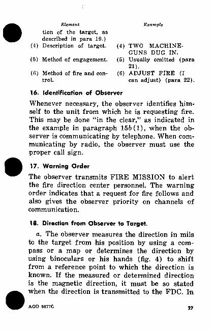
Element Example
tion of the target, as described in para 19.)
(4) Description of target. (4)
(5) Method of engagement. (5)
(6) Method of fire and con- (6) trol.
16. Identification of Observer
Whenever necessary, the observer identifies him- self to the unit from which he is requesting fire. This may be done “in the clear,” as indicated in the example in paragraph 15h(l), when the ob- server is communicating by telephone. When com- municating by radio, the observer must use the proper call sign.
17. Warning Order
The observer transmits FIRE MISSION to alert the fire direction center personnel. The warning order indicates that a request for fire follows and also gives the observer priority on channels of communication.
18. Direction from Observer to Target.
a. The observer measures the direction in mils to the target from his position by using a com- pass or a map or determines the direction by using binoculars or his hands (fig. 4) to shift from a reference point to which the direction is known. If the measured or determined direction is the magnetic direction, it must be so stated when the direction is transmitted to the FDC. In
TWO MACHINE- GUNS DUG IN. Usually omitted (para 21). ADJUST FIRE (I can adjust) (para 22).
AGO 6677C 27
a call for fire the direction is announced to the nearest 10 mils; for example, DIRECTION 4340. When the direction to a reference point has been measured, the direction to the target may be de- termined as follows: First, measure the angle in mils between the reference point and the target. Second, if the target is to the left of the reference point, subtract the angle from the direction of the reference point; if the target is to the right of the reference point, add the angle to the direction of the reference point.
Example 1: The direction from the observer’s position to the reference point has been measured or is known to be 970 mils. A target is located 80 mils to the left of the reference point. Therefore, the angle is sub- tracted from the direction of the reference point. The direction to the target is 890 (970 -80) mils.
Example 2: The direction to the reference point from the observer’s position has been meas- ured with a compass and found to be 4,140 mils. A target appears 200 mils to the right of the reference point, as measured with the binoculars. Since the target is to the right of the reference point, the angle is added to the direction of the reference point. Thus, the direction to the target is 4,340 (4,140 +200) mils.
b. When no direction-measuring instrument is available, the observer must estimate the direc- tion. If the announced direction is in error, it will
28 AGO 8677C
be corrected by; the fire direction center personnel during the course of the adjustment.
c. Direction is announced at that point in the sequence of the call for fire where it can be most efficiently applied by the fire direction center per- sonnel. Depending on the manner in which the location of the target (para 19) is reported, di- rection is announced as follows:
(1) When the target is located by grid co- ordinates, the direction is announced after the coordinates: for example, GRID 476521, DIREC- TION 1920.
(2) When the target is located by a shift from a known point, the direction is announced immediately after the designation of the point from which the shift is being made ; for example, FROM REGISTRATION POINT 1, DIREC- TION 2450, RIGHT 250, ADD 400.
(3) When the target is located by polar co- ordinates, the direction is announced as the first element of the target location ; for example, DIRECTION 1870, DISTANCE 1600.
19. Location of Target
The location of the target may be given in any manner clearly understandable to both the ob- server and the fire direction center personnel. Normally, one of the following methods is used to locate a target:
a. Chid Coordinates. The observer may locate the target by determining its grid coordinates on a map. For example, a target is shown on a map 540 meters east (right) of the south to north
AGO 6677C M
Iftie numbered 37 and 350 meters north (up) from the west to east line numbered 81. The grid coordinates of the target are 3754 and 8135, (to the nearest 10 meters) which are written as 3754 and announced as GRID, THREE, SEVEN, FIVE, FOUR, EIGHT, ONE, THREE, FIVE. Grid coordinates are always read to the right and up from the origin. (See fig. 10 for an ex- ample of a target location by grid coordinates.)
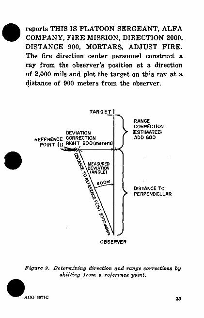
&. Shift from a Known Point. The observer may locate the target by a shift from a reference point, a registration point, a numbered target, or any other point the location of which is known to both the observer and the fire direction center personnel. A shift often may be made from a target previously fired on or from a smoke round fired deliberately into the center of the area to give the observer a point from which to shift the fire to the target (d below). The shift is given as a correction in meters. If no correc- tion is to be made in either range or vertical shift, that element is omitted. The procedure for locating a target by a shift from a known point is discussed in (1) and (2) below and demon- strated in figure 9.
(1) Deviation correction. The deviation an- gle in mils from the known point to the target is measured, and the distance to the reference point is estimated. The correction in meters from the known point to the OT line is then deter- mined by use of the mil relation (para 8) and the observer-known point distance.
(a) The observer measures the angle
30 AGO 6677C
from the observer-known point line to the OT line (400-pi).
(6) By using the observer-known point distance (2,000 meters) as the range in the mil relation, the observer determines the unknown width in meters (to the nearest 10 meters) (W = 2 X 400pi = 800 meters).
(c) The direction correction is included in the call for fire; for example, FROM REGIS- TRATION POINT 1, DIRECTION (so much), RIGHT 800. If the target were left of the regis- tration point, the correction would be FROM REGISTRATION POINT 1, DIRECTION (so much), LEFT 800.
(2) Range correction. The correction for range from the reference point to the target is estimated by the observer (fig. 9). To estimate the range correction, the observer visualizes an imaginary line from the reference point to point A, at a right angle to the OT line. He estimates the distance from point A to the target. This estimated distance—from point A to the target —is the range correction. He announces the cor- rection as ADD 600. If the target were short of point A, the correction announced would be DROP (so much). If the range from the observer to the target were the same as the range from the observer to th^ reference point, the observer would omit any reference to range.
c. Geographic Locations. The observer may lo- cate the target by means of geographic direction and distance from a known point. Examples are—
AGO 6677C 31
FROM TARGET AF4013, DIRECTION 200, WEST 100, SOUTH 300.
FROM ROAD JUNCTION 615, DIREC- TION 1400, DISTANCE 900.
FROM CROSSROADS 932, DIRECTION 600, NORTHEAST 600.
d. Marking. The observer may request a mark- ing round from which he can shift to his target. This procedure is especially useful when the ob- server cannot identify an artillery point, such as a registration point or known point, from which he can shift or when maps or photomaps are not available. Examples of requests for mark- ing are MARK REGISTRATION POINT 1 and MARK CENTER OF SECTOR. The observer may request an airburst to assist him in locating the fire he has requested particularly in terrain having a large amount of undergrowth and woods covering the target area.
e. Polar Coordinates. If the observer’s location is known by the fire direction center personnel, the observer may locate the target initially by giving the direction and distance to the target from his position. This is known as the polar co- ordinate method of locating targets. The fire di- rection center personnel plot the targets on the direction and at the distance from the observer’s location as reported by the observer. This method is particularly desirable in the case of large lateral (horizontal) shifts of fire and short ob- serving (OT) distances. Example: The observer
32 AGO 6677C
reports THIS IS PLATOON SERGEANT, ALFA COMPANY, FIRE MISSION, DIRECTION 2000, DISTANCE 900, MORTARS, ADJUST FIRE. The fire direction center personnel construct a ray from the observer’s position at a direction of 2,000 mils and plot the target on this ray at a distance of 900 meters from the observer.
Figure 9. Determining direction and range corrections by shifting from a reference point.
TARGET I
DEV
REFERENCE C0F
POINT (I) W®
RANGE CORRECTION
(ESTIMATED) ADD 600
DISTANCE TO PERPENDICULAR
OBSERVER
AGO 6677C 33
20. Description of Target
The description of the target includes the size, type, and activity observed. The description should be brief but sufficiently informative to in- dicate to the fire direction center personnel the importance of the target and the best manner of attack. Example: TROOPS MASSING FOR AS- SAULT, LENGTH A00 (meters) WIDTH 200 (meters).
21. Method of Engagement
a. Danger Close. The term DANGER CLOSE will be included in the method of engagement when the target is within 600 meters of friendly forces or prohibited areas.
b. Ammunition and Fuze Action. The type of ammunition and fuze action is usually omitted from the observer’s call for fire, and the fire direction officer automatically directs that high- explosive (HE) shell with a percussion (impact/ point detonating) fuze be used. If the observer wants a different type of shell or fuze action, he may request it: for example, SMOKE. The ob- server may also request the volume of fire he deems necessary in fire for effect; e.g., 3 ROUNDS. For further discussion of fuze action, see paragraph 28.
22. Method of Fire and Control
a. Method of Fire. In area fire the adjustment normally is conducted with the two center pieces of the adjusting battery firing simultaneously. If, because of an unusual condition, the observer de
34 AGO 6677C
termines that another method of fire is more adequate, he asks for it in his call for fire. Other methods of fire are PLATOON (BATTERY) RIGHT (LEFT). BATTERY LEFT (RIGHT) fire may be requested by the observer when, be- cause of the wind blowing across the target, he is unable to get a spotting of the battery fire. In this method of fire, the weapons are fired in suc- cession at 5-second intèrvals, starting with the weapon on the left (right). The time interval al- lows the dust and smoke from each round to clear away before the next round bursts, thereby making spotting easier.
5. Control of Fire. The observer can designate control by including in his call for fire one of the terms defined in (1) through (4) below.
(1) ADJUST FIRE (AF)—Indicates that the observer can and will adjust the fire.
(2) FIRE FOR EFFECT (FFE)—Means that the observer is absolutely sure that the fire requested will be effective without further ad- justment or any adjustment at all. For example, when the target has been adjusted on previously, the observer may send TARGET AF4025, DI- RECTION 5100, FIRE FOR EFFECT.
(3) AT MY COMMAND (AMC)—Used by the observer when he desires that the rounds be fired at specific times as called for by him. When using this method, the observer must give FIRE before the battery or battalion will fire. This method of control remains in effect until CAN- CEL AT MY COMMAND is announced by the observer.
AGO 6677C 35
(4) CANNOT OBSERVE—Used by the ob- server when he is unable to see the target well enough to make an adjustment but believes that a target is at the given location.
23. Information Sent to Observer
a. Upon receipt of a fire mission, the fire direc- tion officer, unless safety or some other considera- tion should interfere, immediately issues instruc- tions, which are referred to as the fire order. From this order the fire commands for the pieces are prepared. Certain elements of the fire order are needed by the observer to inform him of the amount and type of fire which will be delivered. These elements of the fire order are transmitted to the observer at the time the fire order is being announced to the FDC personnel. These elements are indicated by asterisks (*) in the following fire order :
Element Example
*(i>
* (2) (3)
*(4)
*(5)
* (6)
b. is so
Battery (batteries) to fire for effect. Adjusting battery. Ammunition lot and charge. Fuze (when different from observer’s request). Number of rounds in fire for effect. Target number.
BATTALION
BRAVO LOT XY, CHARGE 5 QUICK
3 ROUNDS
TARGET AF4050
If the mission cannot be fired, the observer notified.
c. The fire direction center personnel announce SHOT to the observer as each round (or rounds) in an adjustment is fired. After fire for effect
36 AGO 6677C
is completed, the fire direction center personnel announce ROUNDS COMPLETE to the ob- server.
d. The observer may request that TIME OF FLIGHT or SPLASH be announced by the fire direction center personnel. He can make these requests either at the beginning of the fire mis- sion or at any time during the fire mission. The time of flight is announced by the fire direction center as TIME OF FLIGHT (so many) SEC- ONDS. The warning is announced SPLASH 5 seconds before each round (or rounds) is due to burst. The warning SPLASH is transmitted to the observer to assist him in identifying his own round, to eliminate the requirement for constant search with binoculars, or as a safety measure to allow him to take cover until immediately be- fore he must look for his round to burst. Gen- erally, when the time of flight is long, the fire direction center personnel transmit TIME OF FLIGHT and SPLASH without request. This is usually the case when medium and heavy artil- lery is fired or when high-angle fire is used.
24. Subsequent Corrections
Subsequent corrections are the corrections made in any of the firing data after an adjustment has been started. The observer sends the fire di- rection center personnel the corrections which he wants applied to the next firing. Corrections are given in the following order:
a. Deviation Correction. The observer trans- mits a deviation correction to correct an off-line
AGO 6677C 37
shot by moving the burst or bursts to the right (left) to bring them to the OT line.
b. Distribution Correction. The observer trans- mits a distribution correction to change the loca- tion of bursts or to widen or narrow the dis- tance between bursts. Examples are as follows:
(1) CONVERGE is transmitted to indicate that all bursts are to be converged on a point.
(2) SHEAF (so many meters) is trans- mitted to indicate that an evenly spaced sheaf is to be spread over a width of so many meters.
c. Range Correction. A range correction is given to change the observer burst distance to get the burst nearer the target. For example; if the rounds land between the adjusting point and the observer, he announces a range correction of ADD (so much), if the rounds burst beyond the adjusting point the observer announces DROP. If there is no correction to direction or range the observer will announce REPEAT.
25. Correction of Errors
If, after transmitting his call for fire, the ob- server realizes that he made an error in one of the elements (para 15), he announces CORREC- TION and transmits the correct data for the ele- ment in error. The elements of the call for fire requiring no correction need not be repeated. If any element has been omitted by mistake, the observer transmits the omitted element to the fire direction center as a separate transmission, without repeating the entire call for fire.
38 AGO 6677C
Section III. AREA FIRE
26. General
The purpose of area fire is to cover the target area with fire so that the desired effect will be obtained. In adjusting area fire, the observer establishes a bracket (para 13) as quickly as pos- sible and rapidly reduces the size of the bracket to 100 meters. Dense fire is then immediately brought on the target with fire for effect (para 29). Speed and accuracy during adjustment are important. Speed will allow the fire for effect to catch the enemy by surprise, and accuracy will cause the greatest damage and most casualties before the enemy can move away or take cover. The type of ammunition and the amount of fire requested by the observer depend on the type of target and whether the target is moving; for example, infantry dug in, a machinegun nest, moving vehicles in an open field. A good adjust- ment results in more effective fire.
27. Adjustment
a. General. Paragraph 30 illustrates the adjust- ment of artillery fire in an area fire mission, which is usually conducted with the two center pieces. The other pieces of the battery are used in the adjustment when desired by the observer or as directed by the fire direction officer. The range of the rounds as a whole unit is spotted ; for example, SHORT, LINE: OVER, 5 RIGHT.
b. Deviation. The deviation of the burst center with respect to the OT line is determined (para 12). The burst center is then brought to and kept
AGO 6677C 39
on the OT line. A burst center which is to one side of the OT line is brought to the line by multiplying the observed deviation (angle) in mils by the estimated OT range in thousands and transmitting the resulting correction of RIGHT (LEFT) (so much) (fig. 3) to the fire direction center.
c. Range. Range changes are made in hundreds of meters until a range change of less than 100 meters is required. Normally, range bounds are 200, 400, or 800 meters. A range change of less than 50 meters is not made in an area fire mis- sion. The bracket sought in adjustment depends on the nature of the target and on the knowledge of its location. A bracket of 100 meters is ob- tained prior to fire for effect because most tar- gets that occupy a small area are not expected to move quickly. A larger bracket may be used when firing for effect on a target that occupies a larger area. The fire direction officer may decide on the size of the bracket for fire for effect.
28. Selection of Fuze
The observer should consider the nature of the target in selecting the fuze. The characteristics of the fuzes and the types of targets on which they are effective are discussed in a through c below.
a. Fuze Quick (FQ). Fuze quick bursts on im- pact and is effective against personnel in the open and against materiel. It normally is used for adjustment on a target. Fuze quick is the
40 AGO 6677C

fuze the fire direction officer will fire if the ob- server does not specify a fuze in the call for fire.
b. Fuze Delay (FD). With fuze delay, the projectile has time either to penetrate the ground and produce mine action (burst below the ground surface) or to ricochet before detonation. If the shell ricochets (the projectile hits the ground and bounces back into the air before it bursts), the burst will look like a low airburst. The delayed action of the fuze keeps it from bursting when the projectile first hits. If mine action occurs, the burst will appear as a small column of dust and dirt shooting into the air. Spottings used for height of burst when fuze delay is used are AIR (for ricochet) and GRAZE (for mine action). Fuze delay is effective in penetrating pillboxes, bunkers, and dugouts.
c. Fuze VT (Variable Time). The VT fuze is a radio-activated fuze which detonates the pro- jectile automatically at a predetermined height above the earth’s surface. During the adjustment, fuze quick is employed ; in fire-for-effect, fuze VT is used. Fuze VT is effective against personnel in the open, personnel in entrenchments, and area targets when neutralization is desired.
d. Subsequent Corrections. Where the observer sends erroneous data during adjustment, he cor- rects it by sending CORRECTION, followed by the corrected element. For example, the observer has transmitted LEFT 200, ADD 400. He desires to change ADD 400 to DROP 400. To correct his error he sends CORRECTION, LEFT 200, DROP 400. The word CORRECTION in this case cor-
AGO 6677C 41
rects the entire original transmission in which the error occurred.
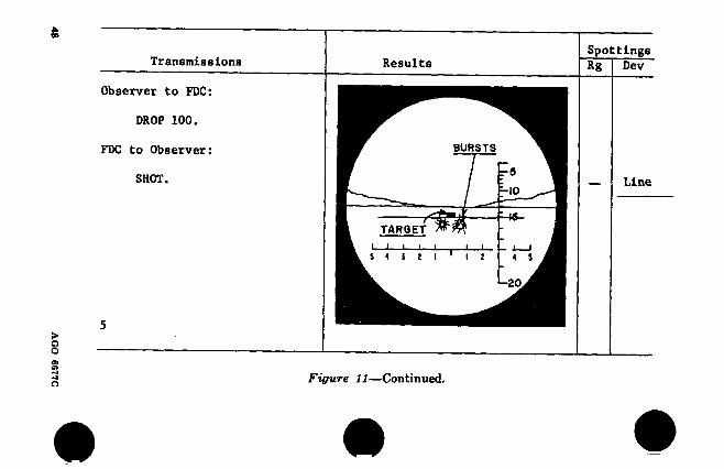
29. Fire for Effect (fig- 11)
a. General. Fire for effect is started when a satisfactory adjustment has been obtained; that is, when the direction of fire and the range are correct or when effective fire will result when the range bracket is split. Range and deviation are spotted for a group of rounds as a whole unit; for example, OVER, LINE (para 27a).
b. Range. The fire direction officer will order an appropriate number of rounds to be fired dur- ing fire for effect. If fire for effect is accurate but insufficient, the observer may obtain addi- tional fire by announcing REPEAT.
c. Surveillance. On completion of fire for ef- fect, the observer tranàmits END OF MISSION (if the fire has been effective and sufficient) and reports the effect which he has observed; for ex- ample, END OF MISSION, 10 ENEMY KILLED, REMAINDER DISPERSED.
30. Illustrative Example, Area Fire Mission
The target is a vehicle park in the open (fig. 11) in the vicinity of the adjusting point; materiel, 105-mm howitzer; ammunition, shell HE. In fig- ure 11, the symbol “ + ” indicates a spotting of over, “ —” a spotting of short, and “?” a spotting of doubtful. (See fig. 10 for observer-target rela- tionship.). In the example in figure 11, the ob- server locates the target on his map. The target is, therefore, designated by means of grid coordi-
42 AGO 6677C
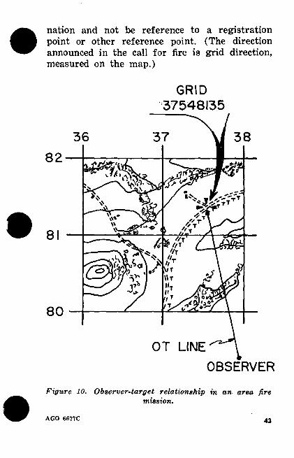
nation and not be reference to a registration point or other reference point. (The direction announced in the call for fire is grid direction, measured on the map.)
GRID 37548135
37 38 36
■'ta 2 »
V' —T «rT
V'* " r ' T
8 //T 6 » //T
'/T
VT w \\r
u1
n. 80
OT LINE
OBSERVER
Figure 10. Observer-target relationship in an area fire mission.
AGO 6677C 43
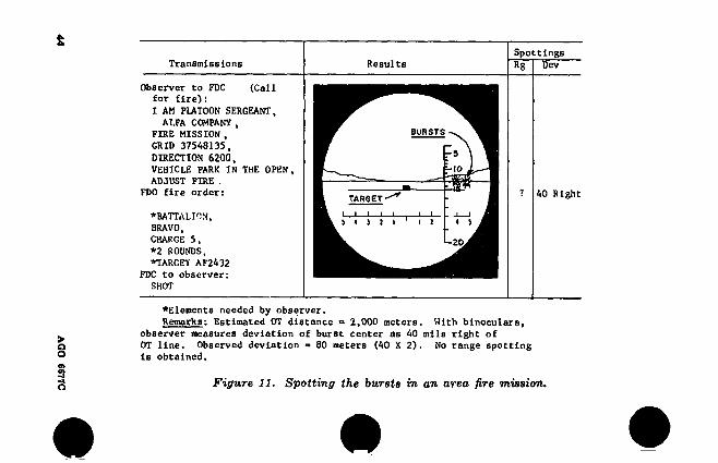
Transmissions Results Spottings
Rg Dev
Observer to FDC (Call for fire)i
I AM PLATOON SERGEANT, ALFA COMPANY ,
FIRE MISSION , GRID 37548135,
DIRECTION 6200, VEHICLE PARK IN THE OPEN, ADJUST FIRE .
FDO fire order:
♦BATTALION, BRAVO, CHARGE 5,
*2 ROUNDS, ♦TARGET AF2432
FDC to observer:
BURSTS
rD
-10
TARGET
I L ' l
L-20
40 Right
SHOT
♦Elements needed by observer. Remarks: Estimated OT distance » 2,000 meters. With binoculars,
observer measures deviation of burst center as 40 mils right of OT line. Observed deviation = 80 meters (40 X 2). No range spotting
is obtained.
Figure 11. Spotting the bursts in an area fire mission.
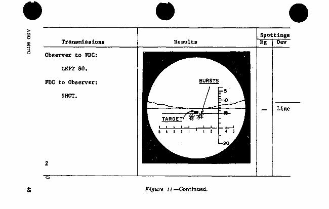
Transmissions
Observer to FDC:
LEFT 80.
FDC to Observer:
SHOT.
2
~
Results
Spottings
Rg Dev
BURSTS
-10
HP TARGET
« S i 2
20
Line
Figure 11—Continued.
AG
O serte
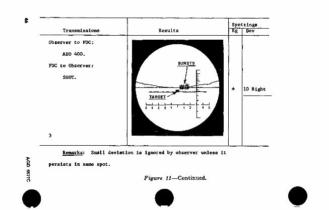
Transmissions Results Spottings Rg Dev
Observer to FDC:
ADD 400.
FDC to Observer:
SHOT.
BURSTS
TARGET
i 2 4 5 5 4 3 2 1
10 Right
Remarks: Small deviation is Ignored by observer unless It
persists in same spot.
Figure 11—Continued.
• #
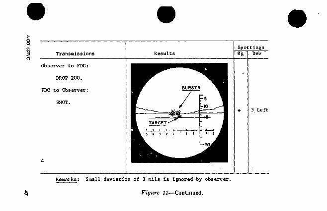
Transmissions
Observer to FDC:
DROP 200.
FDC to Observer:
SHOT.
4
Results
Spottings
Rg Dev
BURSTS
r 5
m TARGET
I I 2 I
L-2Q
3 Left
Remarks : Small deviation of 3 mils is ignored by observer.
Figure 11—Continued.
Transmissions
Observer to FDC:
DROP 100.
FDC to Observer:
SHOT.
Results Spottings
Rg Dev
BURSTS
1-5
-10
fWi TARGET
I I 4 S
L-20
Line
Figure 11—Continued.

AG
O
6677C
Transmissions
Observer ¿o PDC:
ADD SO, FIRE FOR EFFECT.
PDC to Observer:
FIRING FOR EFFECT.
Kg Dev
BURSTS
-S Rang Line
-10
ecc
TARGET
14 1t 4 S
-20
Remarks: First rounds in effect spotted range correct, line.
Remainder of fire is observed and, if necessary, corrections arc
sent .to the fire direction center
Observer to PDC:
END OP MISSION,
2 VEHICLES DESTROYED, -
10 ENEMY KILLED.
« Figure 11—Continued.
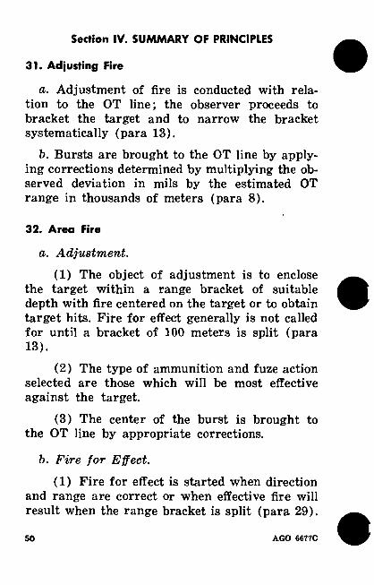
Section IV. SUMMARY OF PRINCIPLES
31. Adjusting Fire
a. Adjustment of fire is conducted with rela- tion to the OT line; the observer proceeds to bracket the target and to narrow the bracket systematically (para 13).
b. Bursts are brought to the OT line by apply- ing corrections determined by multiplying the ob- served deviation in mils by the estimated OT range in thousands of meters (para 8).
32. Area Fire
a. Adjustment.
(1) The object of adjustment is to enclose the target within a range bracket of suitable depth with fire centered on the target or to obtain target hits. Fire for effect generally is not called for until a bracket of 100 meters is split (para 13).
(2) The type of ammunition and fuze action selected are those which will be most effective against the target.
(3) The center of the burst is brought to the OT line by appropriate corrections.
b. Fire for Effect.
(1) Fire for effect is started when direction and range are correct or when effective fire will result when the range bracket is split (para 29).
so AGO 6677C

(2) Fire for effect is started at the center range of the established bracket.
(3) Deviation is corrected on entering fire for effect so that the fire is centered on the target or the area to be covered.
(4) The range should be improved if the bulk of the fire for effect is over or short. The direction is established properly when the sheaf is centered on the target.
(5) If the fire for effect is ineffective or in- sufficient, necessary corrections are made and ad- ditional fire for effect is requested.
(6) On completion of fire for effect, the ob- server transmits END OF MISSION and reports the effect observed.
Section V. SUGGESTIONS FOR SPECIAL SITUATIONS
33. Lost Rounds
If the terrain is rough or if the observer’s loca- tion of the target is in error to the extent that he cannot see the first round, the round is spotted as LOST. The observer may see smoke or dust rising from the burst (para 12) or hear the sound of the burst. If the observer cannot locate the burst, he should spot the round as LOST, then take the actions indicated in a or b below.
a. Ask for a change in range or direction that may bring the burst into open terrain. Care must be taken to insure that the next burst is not moved into an area occupied by friendly troops.
b. Ask for a round of smoke or white phosphorus.
AGO 6677C 51
34. Targets Close to Friendly Troops
When a target is close to friendly troops, fire should be opened at a range that definitely re- sults in a burst beyond the target. For friendly troop safety, it is advisable to request that the first round in adjustment be a smoke round. The observer will include in his call for fire the term DANGER CLOSE when firing within 600 meters of friendly troops. The adjustment may be con- ducted using the whole battery rather than a platoon. In addition, the observer should make range correction of 50 to 100 meters and not at- tempt to bracket the target. Range corrections of less than 25 meters are not made. However, as the bursts are brought close to the target, the observer may use a series of 25-meter range cor- rections until he obtains a range correct or a short splotting. This type of adjustment is called creeping.
35. Control of Fire
If smoke obscures the target or if, for any reason, the observer desires to control the actual time the weapons fire, he transmits AT MY COM- MAND to the fire direction center. In this case, fire direction center personnel report BATTERY IS READY when the weapons are ready to fire. When the observer desires that the weapons fire, he commands FIRE. When the necessity for fir- ing at his command ceases, the observer includes the phrase CANCEL AT MY COMMAND in his next message.
S3 AGO 6677C
Section VI. OBSERVATION
36. General
The artillery forward observer often will not be able to occupy an observation post which will permit him to see all the targets which appear in his area of responsibility. The combat soldier can fill any gaps in the forward observer’s field of view. These gaps may exist on a probable avenue of approach, on a boundary between units, or in any area in which the assigned forward observer cannot see. In the course of his normal duties, the combat soldier often will have an op- portunity to occupy a vantage point from which he will be able to observe targets and adjust artillery fire. He will find the information in paragraph 37 useful in establishing an observa- tion post.
37. Selection of Observation Posts e
a. General. Observation posts should be se- lected to obtain a wide and deep field of view. Consideration should be given to the ease of con- cealment of the location and the routes leading to the observation post, the ease of installation, the maintenance of communications, and the avoidance of prominent landmarks.
b. Alternate Observation Post. After locating and establishing the best available observation post, the observer selects and prepares an alter- nate observation post. He occupies the alternate post if he is discovered by the enemy or is re- quired to move for any other reason.
AGO 6677C 53
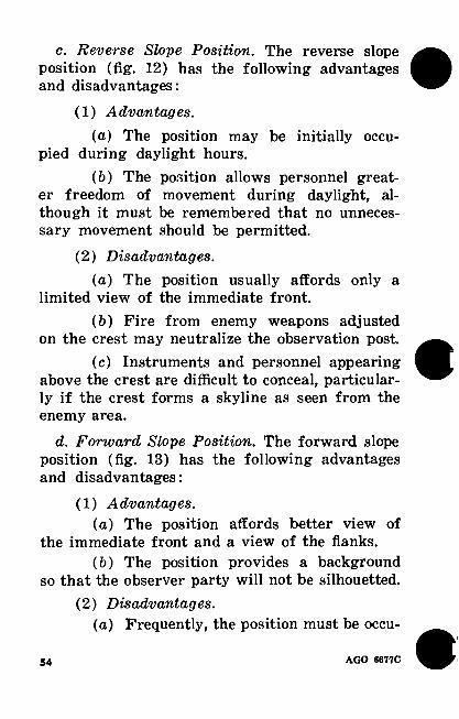
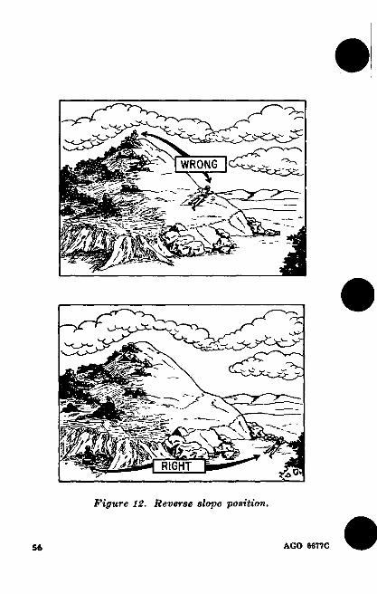
c. Reverse Slope Position. The reverse slope position (fig. 12) has the following advantages and disadvantages:
(1) Advantages.
(a) The position may be initially occu- pied during daylight hours.
(ft) The position allows personnel great- er freedom of movement during daylight, al- though it must be remembered that no unneces- sary movement should be permitted.
(2) Disadvantages.
(a) The position usually affords only a limited view of the immediate front.
(b) Fire from enemy weapons adjusted on the crest may neutralize the observation post.
(c) Instruments and personnel appearing above the crest are difficult to conceal, particular- ly if the crest forms a skyline as seen from the enemy area.
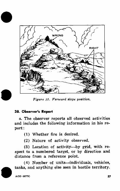
d. Forward Slope Position. The forward slope position (fig. 13) has the following advantages and disadvantages:
(1) Advantages. (a) The position affords better view of
the immediate front and a view of the flanks. (b) The position provides a background
so that the observer party will not be silhouetted. (2) Disadvantages.
(a) Frequently, the position must be occu-
54 AGO 6677C

pied under cover of darkness to prevent discovery.
(b) The observer may not be able to change positions during daylight without risk of disclosing his position.
(c) Maintenance of wire communications during daylight is often impractical and difficult.
AGO 6677C 55
^>2 X
N WRONG TV
X
fi /T,
RIGHT o*
Figure 12. Reverse slope position.
AGO 8877C
WRONG
RIGHT r¿.
z—5
v, RIGHT
¡K-
Figure 13. Forward slope position.
38. Observer's Report
a. The observer reports all observed activities and includes the following information in his re- port:
(1) Whether fire is desired. (2) Nature of activity observed. (3) Location of activity—by grid, with re-
spect to a numbered target, or by direction and distance from a reference point.
(4) Number of units—individuals, vehicles, tanks, and anything else seen in hostile territory.
AGO 6677C" 57
For example, five men on bicycles; two medium tanks; etc.
(5) Direction and speed of movement in hostile territory.
(6) Location and movement of friendly for- ward elements, with regard for the security of such information.
b. The observer reports exactly what he ob- serves and never infers, or deduces, from his observation.
c. During intervals when no activity is ob- served, he makes periodic negative reports.
39. Auxiliary Map Data
a. Augmentation of Maq> Data. As soon as the observer has oriented himself, he should begin a systematic augmentation of map data. The map is augmented with lines of direction radiating from the observer’s position at convenient angu- lar intervals. These lines are intersected with arcs of distance by using the observer’s position as the center (fig. 14). The observer then marks points of importance which were not included on the map when it was printed. He also marks (empha- sizes) any points which he might frequently need, such as reference points, registration points, targets, and likely points of enemy activity.
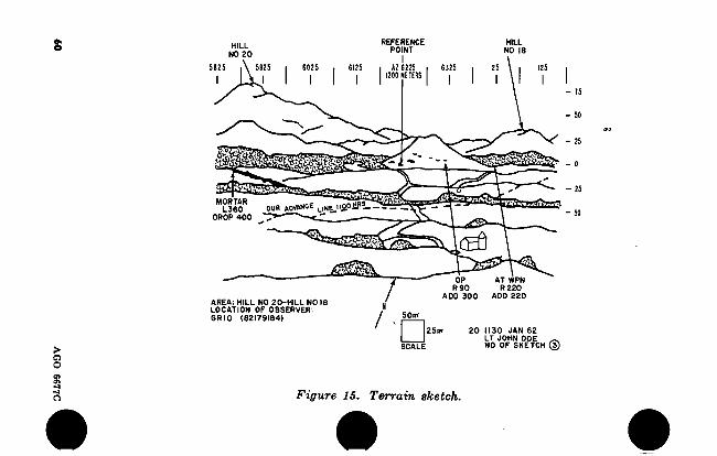
b. Terrain Sketch. A rough sketch of the ter- rain on which the observer expects to select tar- gets and adjust fire (fig. 15) will help him to determine the locations of targets. If known, such points as the registration point, reference points, and target should be drawn on the sketch in
58 AGO 6677C
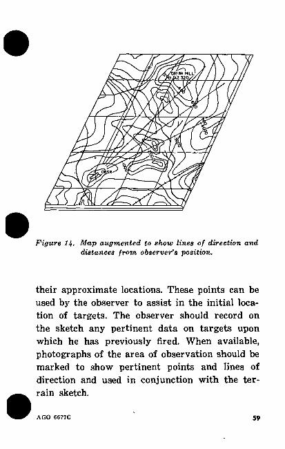
Figure 14. Map augmented to show lines of direction and distances from observer’s position.
their approximate locations. These points can be used by the observer to assist in the initial loca- tion of targets. The observer should record on the sketch any pertinent data on targets upon which he has previously fired. When available, photographs of the area of observation should be marked to show pertinent points and lines of direction and used in conjunction with the ter- rain sketch.
AGO 6677C 59
AG
O
6677C
S REFERENCE
POINT HILL
H LL NO 6
NO 20
5925 6025 6125 i AZ 6225 , 6325 ■ I200 NEIERS i
- 75
MORTAR b* OUR ADVANCE L,ME n¿oüR!- L360
DROP 400
CEO
AREA: HILL NO 20-HILL NO 18 LOCATION OF OBSERVER:
GRID (82179164) 9WH1
R 90 R220 ADD 300 ADD 220
20 1130 JAN 62 LT JOHN DOE ^ NO OF SKETCH ®
90
Figure 15. Terrain sketch.

Section VII. COMMUNICATIONS
40. Communication Procedures
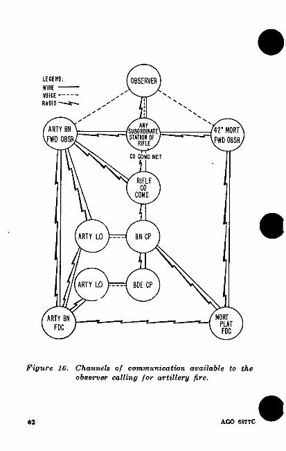
a. Normally, there is a field artillery liaison officer with each airborne infantry, mechanized infantry, infantry, and tank battalion and a field artillery forward observer with each committed rifle and tank company. The liaison officer and forward observer are equipped with radio and telephone equipment with which they can send fire missions to the field artillery unit without delay (fig. 16). When an artillery observer is not available, fire missions may be sent to the artillery unit in one of several ways. Some meth- ods of communicating with the field artillery unit are as follows:
(1) Any station in the rifle company com- mand net or in the company wire system can contact the field artillery forward observer by radio or telephone. The forward observer has the necessary equipment to operate in both systems. He can receive the fire mission through either system and relay it to the field artillery unit through artillery channels, utilizing either radio or wire. In addition, the platoon leader can be reached through the squad leader’s radio and tele- phone. The platoon leader can then contact the artillery forward observer on the company net or wire system.
(2) If the artillery forward observer cannot be reached by one of the aforementioned methods, the company commander’s communication chan- nels, either wire or radio, may be used to relay calls for fire to the infantry battalion or brigade
AGO 6677C 61
LEGEND:
WIRE VOICE RADIO
OBSERVER
f ANY ' SUBORDINATE STATION OF ^ RIFLE J
ARTY BN FWO OBSR
42’ MORT FWD OBSR
CO COMD NET
RIFLE CO
COMO
ARTY LO BN CP
ARTY LO BDE CP
MORT PLAT F DC
ARTY I FDC
Figure 16. Channels of communication available to the
observer calling for artillery fire.
62 AGO 6677C
headquarters, where the artillery unit liaison of- ficer can transmit the fire missions to the field artillery unit through artillery channels, utiliz- ing either wire or radio communications. Addi- tionally, if the artillery frequency is known, any- one with a valid request for fire may enter the artillery net directly.
b. Field artillery battalions of the armored division artillery rely principally on the use of radio communications. The use of wire (tele- phone) communications is not practical for armor units when they are moving rapidly; therefore, all tanks of an armored division have radios. The field artillery forward observer with a tank unit usually has a tank assigned to him.
c. The airborne division artillery normally maintains the same radio and telephone commu- nication systems as the infantry division artil- lery.
41. Phonetic Alphabet
a. The phonetic alphabet (shown below) is a list of words used to identify letters in a message transmitted by radio or telephone. The purpose of the phonetic alphabet is to assist in clarifying and identifying letters or words which might be difficult to hear or understand over a radio or telephone. A ALFA B BRAVO C CHARLIE D DELTA E ECHO F FOXTROT
G GOLF H HOTEL I INDIA J JULIETT K KILO L LIMA
AGO 6677C 63
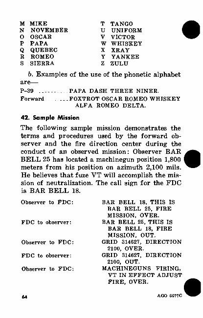
M MIKE T TANGO N NOVEMBER U UNIFORM O OSCAR V VICTOR P PAPA W WHISKEY Q QUEBEC X XRAY R ROMEO Y YANKEE S SIERRA Z ZULU
b. Examples of the use of the phonetic alphabet are— P-39 PAPA DASH THREE NINER. Forward FOXTROT OSCAR ROMEO WHISKEY
ALFA ROMEO DELTA.
42. Sample Mission
The following sample mission demonstrates the terms and procedures used by the forward ob- server and the fire direction center during the conduct of an observed mission: Observer BAR BELL 25 has located a machinegun position 1,800 meters from his position on azimuth 2,100 mils. He believes that fuze VT will accomplish the mis- sion of neutralization. The call sign for the FDC is BAR BELL 18.
Observer to FDC:
FDC to observer:
Observer to FDC:
FDC to observer:
Observer to FDC:
BAR BELL 18, THIS IS BAR BELL 25, FIRE MISSION, OVER.
BAR BELL 25, THIS IS BAR BELL 18, FIRE MISSION, OUT.
GRID 314627, DIRECTION 2100, OVER.
GRID 314627, DIRECTION 2100, OUT.
MACHINEGUNS FIRING, VT IN EFFECT ADJUST FIRE, OVER.
64 AGO 6677C
F DC to observer:
Observer to FDC:
FDC to observer: Observer to FDC:
Observer’s spotting Observer to FDC: FDC to observer:
Observer to FDC: Observer’s spotting
Observer to FDC:
FDC to observer:
Observer to FDC: Observer’s spotting
Observer to FDC:
FDC to observer:
Observer to FDC: Observer’s spotting
Observer to FDC: FDC to observer:
Observer to FDC: Observer’s spotting
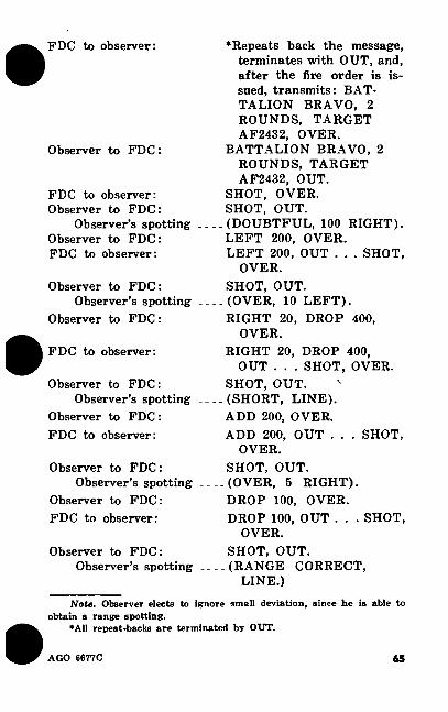
‘Repeats back the message, terminates with OUT, and, after the fire order is is- sued, transmits : BAT- TALION BRAVO, 2 ROUNDS, TARGET AF2432, OVER.
BATTALION BRAVO, 2 ROUNDS, TARGET AF2432, OUT.
SHOT, OVER. SHOT, OUT.
.(DOUBTFUL, 100 RIGHT). LEFT 200, OVER. LEFT 200, OUT . . . SHOT,
OVER. SHOT, OUT.
.(OVER, 10 LEFT). RIGHT 20, DROP 400,
OVER. RIGHT 20, DROP 400,
OUT . . . SHOT, OVER. SHOT, OUT.
.(SHORT, LINE). ADD 200, OVER. ADD 200, OUT . . . SHOT,
OVER. SHOT, OUT.
.(OVER, 5 RIGHT). DROP 100, OVER. DROP 100, OUT . . . SHOT,
OVER. SHOT, OUT.
.(RANGE CORRECT, LINE.)
Note. Observer elects to ignore small deviation, since he is able to
obtain a range spotting. *A11 repeat-backs are terminated by OUT.
AGO 6677C 65
Observer to FDC:
FDC to observer:
Observer to FDC: FDC to observer:
Observer to FDC :
FDC to observer:
FIRE FOR EFFECT, OVER.
FIRE FOR EFFECT, OUT . . . SHOT, OVER.
SHOT, OUT. ROUNDS COMPLETE,
OVER. ROUNDS COMPLETE,
OUT . . . END OF MIS- SION, MACHINEGUNS SILENCED, OVER.
END OF MISSION, MACHINEGUNS SILENCED, OUT.
66 AGO 6677C
APPENDIX A
REFERENCES
AR 320-5 Dictionary of United States Army Terms.
AR 320-50 Authorized Abbreviations and Brevity Codes.
DA Pam 108-1 Index of Army Films, Trans- parencies, GTA Charts, and Recordings.
DA Pam 310-series Military Publications In- dexes.
FM 6-10 Field Artillery Communica- tions.
FM 6-40
FM 7-11
FM 17-15
FM 21-5
FM 21-6
Field Artillery Cannon Gunnery.
Rifle Company, Infantry, Airborne, and Mechanized.
Tank Units, Platoon, Com- pany, and Battalion.
Military Training Manage- ment.
Techniques of Military In- struction.
AGO 6677C 67
FM 21-26
FM 21-30
TM 9-1900
Map Reading.
Military Symbols.
Ammunition, General.
ACP, 125 US Supp U.S. Supp-2 Radiotelephone Procedure for Conduct of Artillery and Naval Gun- fire.
«8 AGO 6677C
APPENDIX B
HINTS FOR THE OBSERVER
1. Develop skill in reading maps and photo- graphs.
2. Be able to orient maps and know your loca- tion at all times, develop skill in using the com- pass.
3. Prepare a terrain sketch and keep it current. 4. Mark obstacles such as boobytraps and anti-
personnel and antitank mines and report their locations to higher headquarters.
5. Dig foxholes deep. Keep all your equipment (rations, communication equipment, etc.) under cover to prevent discovery of your position by the enemy. Items with reflective surfaces are espe- cially revealing. If possible, dig a connecting com- munication trench.
6. Know the destination, route, and time of friendly patrols so that you will not bring artil- lery fire on them.
7. Always know the locations of forward friendly elements.
8. Be able to use binoculars skillfully. 9. Enemy guns, especially antitank guns which
first open fire on our attacking forces, are usu- ally in the second line of defense. The close-up guns are waiting for an easy kill. Be on the lookout and see them first.
AGO 6677C 69
10. Even though you see only a small part of an object, such as a gun, tank, vehicle, or anti- tank gun, be able to identify it as enemy equip- ment.
11. Remember that CONTINUOUS AND CLOSE WATCHING of the target area is vitally important and may save valuable life and equip- ment.
12. Prompt and proper treatment of wounds will prevent shock, one of the real killers on the battlefield. Know the locations of aidmen and the infantry aid station.
13. When planning a forward movement, make a personal reconnaissance if possible. If a personal reconnaissance is impossible, carefully study air photographs.
14. Use every pair of eyes available to you to observe and designate targets for you; there are many pairs of eyes in your unit.
15. Know these words: WHO? WHAT? WHEN? WHERE? HOW? They are the key words for all observers and intelligence person- nel when reporting enemy activities.
OBSERVER’S NOTES (RECORD OF ADJUSTMENT)
The observer or his assistant may record the cor- rections transmitted to the fire direction center while adjusting fire. This is not necessary, but the notes will be helpful to the observer who has trouble remembering the size of his bracket and his last correction.
70 AGO 6677C
INDEX
Paragraph
Adjusting fire 31 Adjusting point 14 Adjustment 27, 30, 32 Alphabet, phonetic 41 Alternate observation post 37 Angles, measuring 8, 11 Announcement of numbers 9 Appropriate artillery targets 3 Area fire:
Adjustment 27, 30, 32 29, 32
26 36
3 39
4 22 11 13
26 27 13 15 7
3, 40 8, 11
6 22, 35
15 25
Fire for effect General
Area of observation Artillery fire, obtaining _ Auxiliary map data Basic technical knowledge Battery left (right) Binoculars, use Bounds, range Bracket :
Area fire - _ Size
Bracketing, procedure Call for fire Check firing Communication Computing direction shift Conduct of fire, general _ _ Control of fire _ Correction of errors:
Direction Initial call for fire
Page
50 24
39, 42, 50 63 53
13, 17 15
3
39, 42, 50 42, 50
39 53
3 58
5 34 17 23
39 39 23 25 8
3, 61 13, 17
8 34, 52
25 38
AGO 6677C 71
Paragraph Page
Subsequent 24 37 Data, map, auxiliary 39 58 Designating location of target 19 29 Determination of direction 18 27 Deviation spottings 12 17 Direction and distribution, area 27 39
fire. Direction, determination 18 27 Direction shift, computing 8, 11 13, 17 Distance 10, 11 16, 17 End of mission — 7 8 Errors, correction 25 38 Estimation of lateral distance 11 17 Field artillery gunnery team 5 6
Fire : Adjusting principles 31 50 Area, general 26 39 Close to friendly troops 13, 34 23, 52 Conduct, general 6 8 Control 23, 35 36, 52 For effect: 32 50 Order, from fire direction 23 36
officer to observer. Requesting 14, 20 24, 34 Ricochet 28 40
Fire direction center 5 6 Forward slope observation post .. 37 53 Fuze, selection 28 40 Grid _ 19 29 Hints for observers app B 69 Information sent to observer 23 36 Initial range change 13 23 Lateral distance 11 17 Lost rounds 7, 33 8, 51 Map data, augmentation 39 58 Marking rounds 19 29 Measuring angles 8, 11 13, 17 Mil relation 8 13 Nature of target .. 20 34
72 AGO 6677C
Paragraph
Nonartillery observers 36, 38, 40 Numbers, announcement Observation Observation post Observer :
Communications Information sent Nonartillery - Notes Reports
Observer-target distance Observer-target line Obtaining artillery fire Order :
Fire, from fire direction offi- cer to observer.
Warning Phonetic alphabet Polar coordinates Procedures, communication Radio communications Range :
Bounds Change Correction Estimation - Spotting
Record of adjustment References Relation, mil Repeat Reports of observers _ Requesting fires:
Ammunition and fuze action _ Call for fire Control Description of target - Identification of observer Location of target
9 36 37
3, 40 23 36
app B 38
10, 14 14, 31
3
23
18,
17 41 19 40 40
13 27
19, 25 10, 11
12 B A 8
29 38
22 15 22 20 16 19
app app
29,
3,
Page
53, 57, 61 15 53 53
3, 61 36 53 69 57
16, 24 24, 50
3
36
27 63
27, 29 61 61
23 39
29, 38 16, 17
17 69 67 13 42
42, 57
34 25 34
3, 34 27 29
AGO 6677C 73

Paragraph Page
Method of engagement 21 34 Method of fire and control - - 22 34 Warning order - 17 27
Reverse slope observation post .. 37 53 Ricochet fire 28 40 Rounds lost 7, 33 8, 51 Selection of ammunition 22 34 Shift from reference point 11, 19 17, 29 Sketch, terrain 39 58 Splash 23 36 Spottings 12 17 Subsequent calls for fire 24 37 Subsequent corrections 25 38 Target:
Artillery, appropriate 3 3 Description 20 34 Location 19 29
Team, field artillery gunnery 5 6 Technical knowledge, basic 4 5 Terminology 7 8 Terrain sketch 39 58 Time of flight 23 36 Warning order 17 27 Wire communications 40 61
74 AGO 6677C
By Order of the Secretary of the Army :
Official : KENNETH G. WICKHAM, Major General, United States Army, The Adjutant General.
W. C. WESTMORELAND, General, United States Army, Chief of Staff.
Distribution : To be distributed in accordance with DA
Form 12-11 requirements for Adjustment of Artillery Fire By The Combat Soldier FA Battery.


«


3000015794 •

e
Cv
FM 6
-135
AD
JU
ST
ME
NT O
F A
RT
ILL
ER
Y
FIR
E
BY
TH
E C
OM
BA
T S
OL
DIE
R-1
96
9