Flying the Garmin G1000 - Ed Williams' Aviation Page
24
Flying the Garmin G1000 Ed Williams CFII/ATP SMX-XX April 2008 An intro to glass panels… Primary Flight Display (PFD) Multi-Function Display (MFD)
-
Upload
khangminh22 -
Category
Documents
-
view
0 -
download
0
Transcript of Flying the Garmin G1000 - Ed Williams' Aviation Page
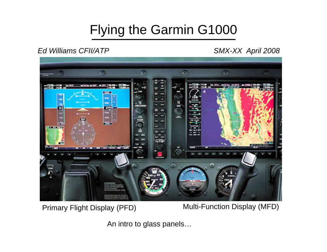
Flying the Garmin G1000Ed Williams CFII/ATP SMX-XX April 2008
An intro to glass panels…
Primary Flight Display (PFD) Multi-Function Display (MFD)

Garmin’s G1000 panel dominates the new airplane market
Cessna 172, 182, T206Beech G36Columbia 400Diamond DA40, DA42Mooney Ovation 20RTiger AG-5BVLJ’s etc…
• The promise is greater functionality at lower cost.• Better maintainability and reliability than analog instrumentation?• Not just data, but information.
Diamond DA42 twinstar
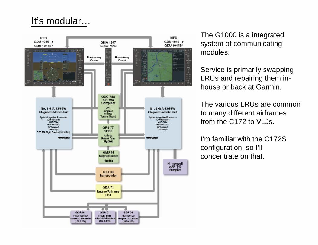
The G1000 is a integrated system of communicating modules.
Service is primarily swapping LRUs and repairing them in-house or back at Garmin.
The various LRUs are common to many different airframes from the C172 to VLJs.
I’m familiar with the C172S configuration, so I’ll concentrate on that.
It’s modular…
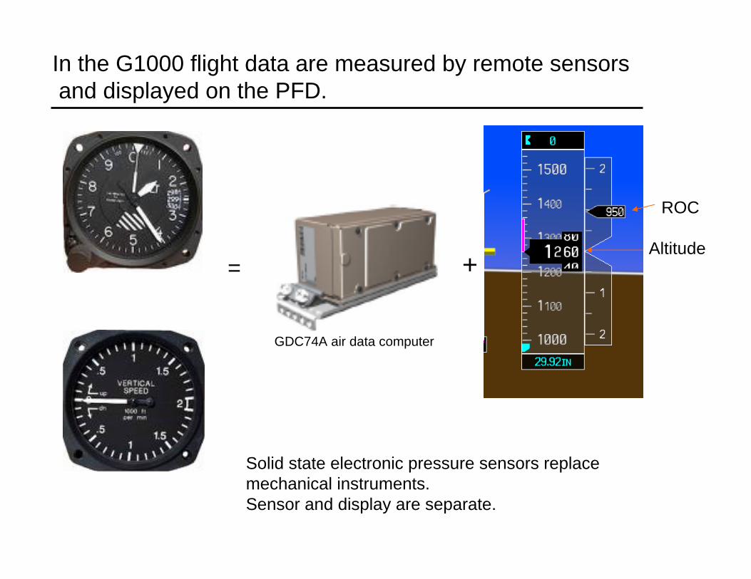
In the G1000 flight data are measured by remote sensorsand displayed on the PFD.
= +
GDC74A air data computer
Altitude
ROC
Solid state electronic pressure sensors replace mechanical instruments.Sensor and display are separate.
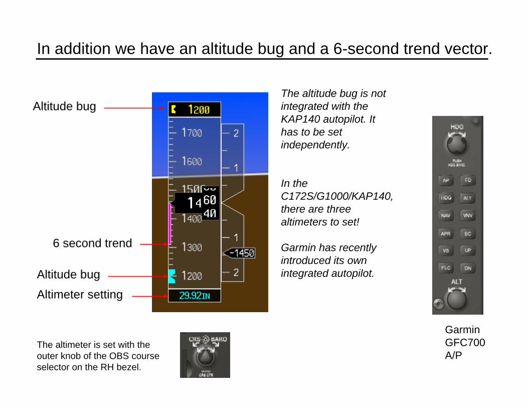
In addition we have an altitude bug and a 6-second trend vector.
Altitude bug
Altimeter setting
6 second trend
The altitude bug is not integrated with the KAP140 autopilot. It has to be set independently.
In the C172S/G1000/KAP140, there are three altimeters to set!
Garmin has recently introduced its own integrated autopilot.
GarminGFC700A/P
Altitude bug
The altimeter is set with the outer knob of the OBS course selector on the RH bezel.
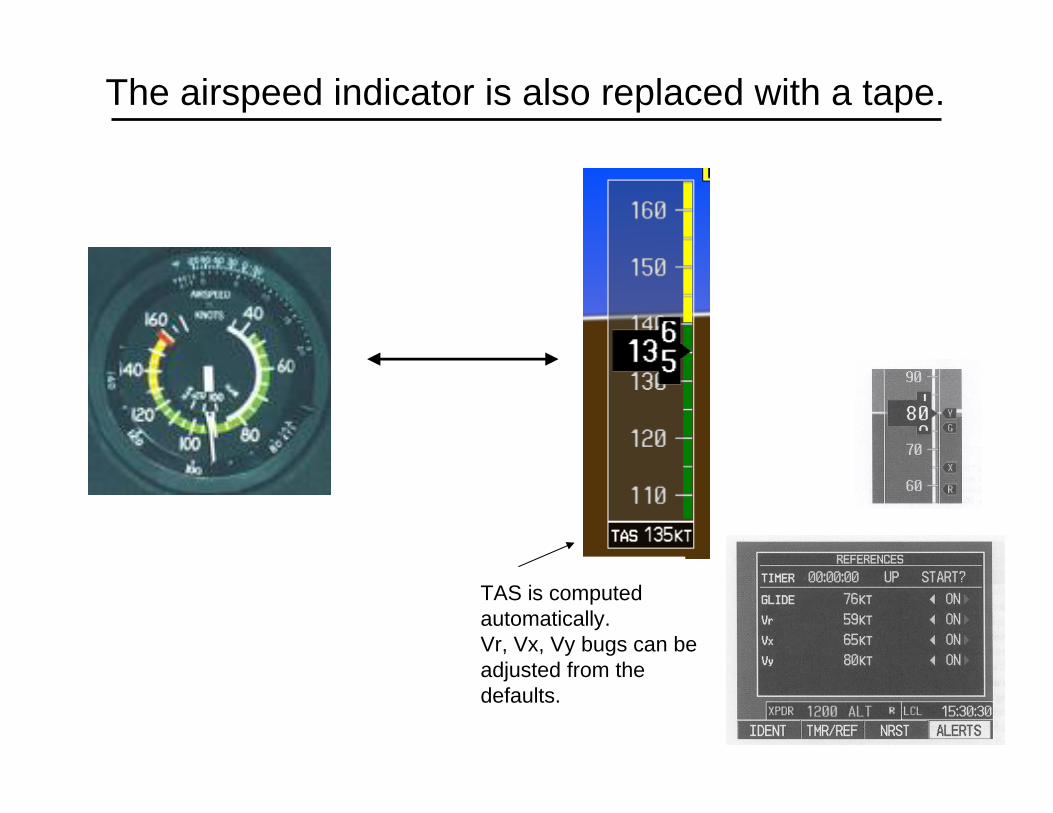
The airspeed indicator is also replaced with a tape.
TAS is computed automatically.Vr, Vx, Vy bugs can be adjusted from the defaults.
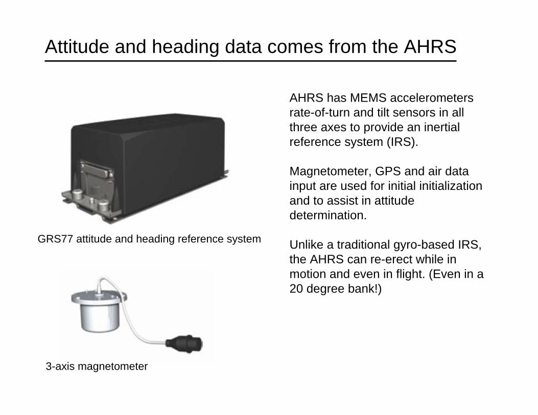
Attitude and heading data comes from the AHRS
GRS77 attitude and heading reference system
3-axis magnetometer
AHRS has MEMS accelerometers rate-of-turn and tilt sensors in all three axes to provide an inertial reference system (IRS).
Magnetometer, GPS and air data input are used for initial initialization and to assist in attitude determination.
Unlike a traditional gyro-based IRS, the AHRS can re-erect while in motion and even in flight. (Even in a 20 degree bank!)

The AHRS will degrade into a reversionary mode if external inputs are lost. It has some redundancy…
Normal AHRSAHRS w/o magnetometer
The “ball”.
Rate of turn(6 sec trend)
Standard rate mark.
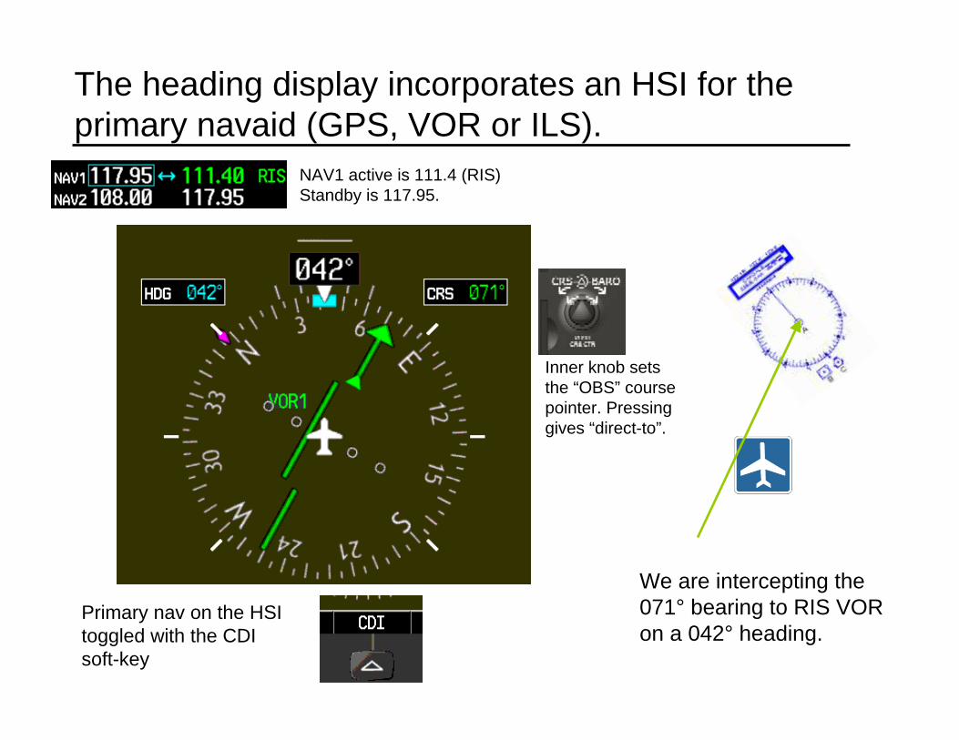
The heading display incorporates an HSI for the primary navaid (GPS, VOR or ILS).
We are intercepting the 071° bearing to RIS VOR on a 042° heading.
Inner knob sets the “OBS” course pointer. Pressing gives “direct-to”.
NAV1 active is 111.4 (RIS) Standby is 117.95.
Primary nav on the HSI toggled with the CDI soft-key
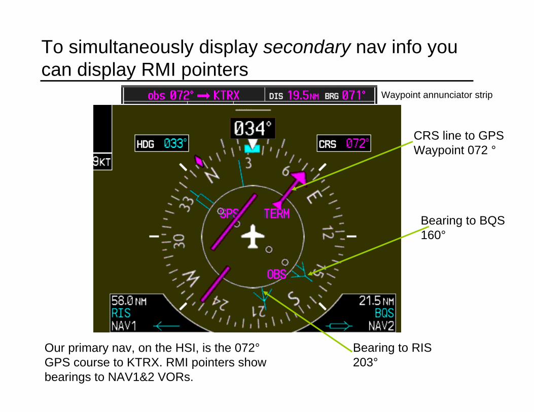
To simultaneously display secondary nav info you can display RMI pointers
Bearing to BQS160°
Bearing to RIS203°
CRS line to GPSWaypoint 072 °
Our primary nav, on the HSI, is the 072°GPS course to KTRX. RMI pointers show bearings to NAV1&2 VORs.
Waypoint annunciator strip
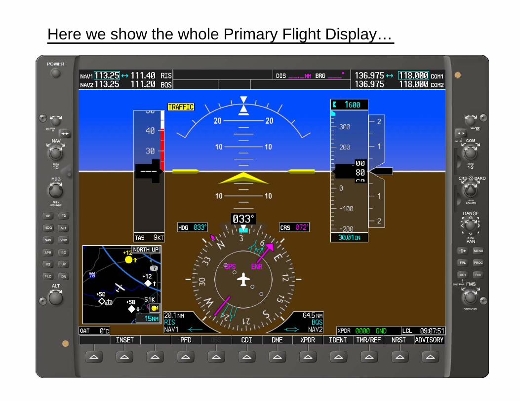
Here we show the whole Primary Flight Display…
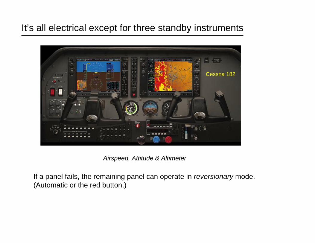
It’s all electrical except for three standby instruments
Airspeed, Attitude & Altimeter
Cessna 182
If a panel fails, the remaining panel can operate in reversionary mode.(Automatic or the red button.)
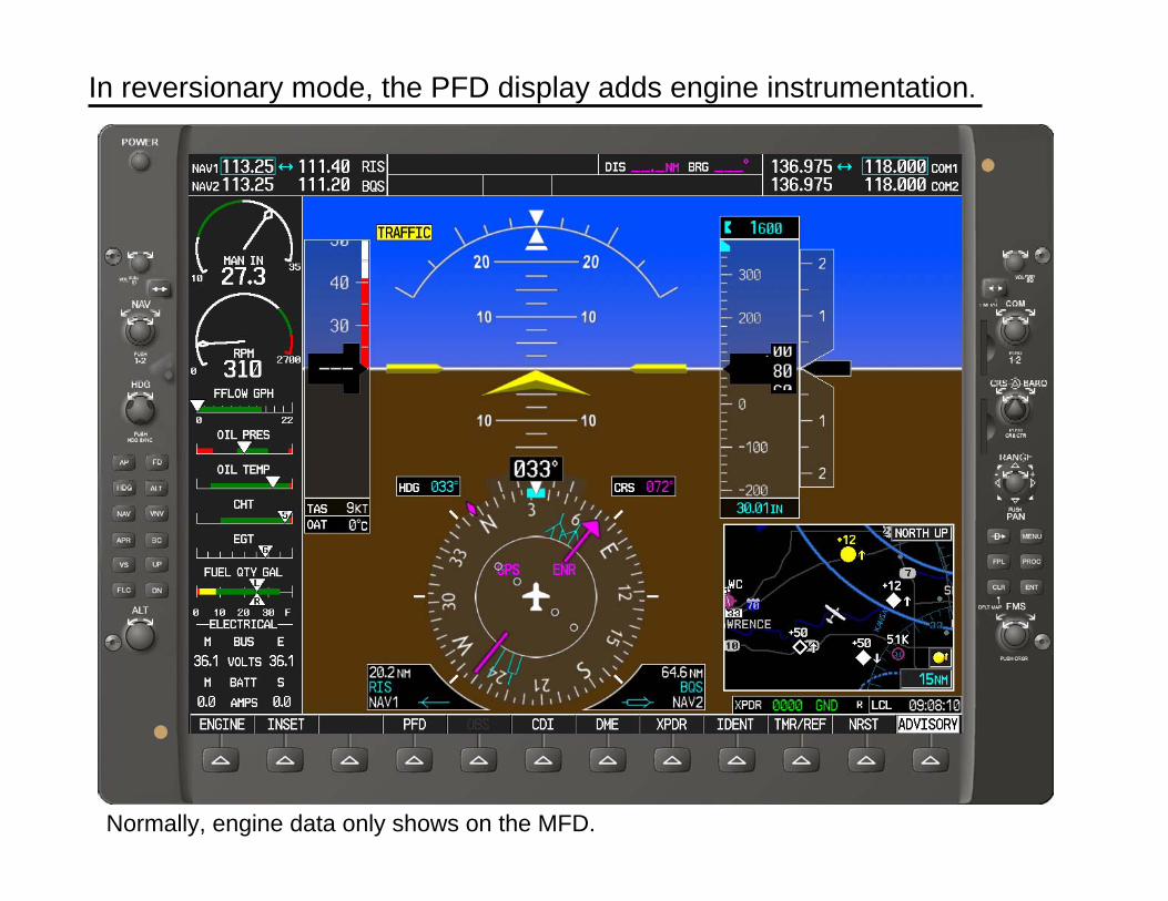
In reversionary mode, the PFD display adds engine instrumentation.
Normally, engine data only shows on the MFD.

In the C172/Garmin 1000 a standby battery can power the essential bus.
• Essential bus powers PFD, AHRS, engine/airframe sensors, #1 Nav-Com and 1 GPS.
• If the alternator fails, turning off the master switch and leaving the stand-by battery switch armed will allow you to preserve main battery capacity for later in the flight.
• The standby battery has little or no power remaining once the essential bus voltage drops to 20V.
(excerpted from the C172S manual)
From the starting checklist:
4. STBY BATT Switch – TEST (hold for 20 sec, verify the green test lamp does not go out), then ARM (verify PFD comes on)
checks the condition of the standby battery.
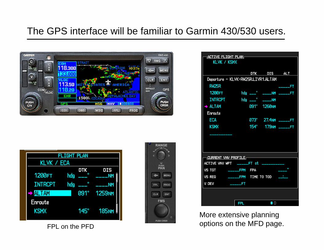
The GPS interface will be familiar to Garmin 430/530 users.
FPL on the PFD
More extensive planning options on the MFD page.
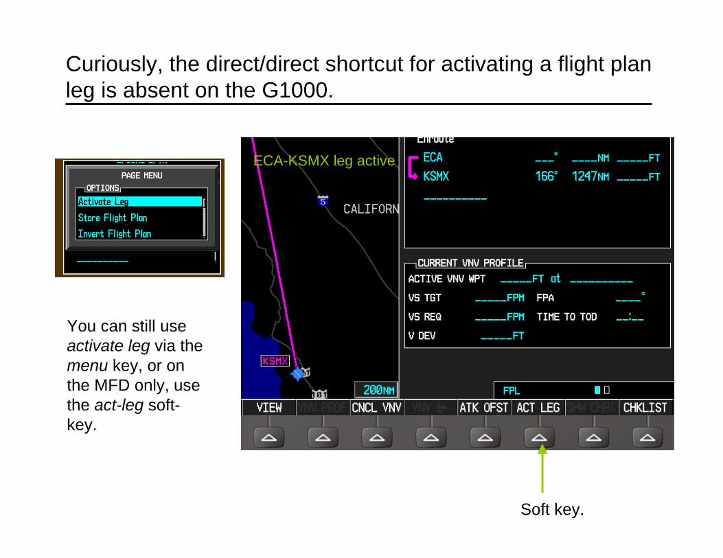
Curiously, the direct/direct shortcut for activating a flight plan leg is absent on the G1000.
You can still use activate leg via the menu key, or on the MFD only, use the act-leg soft-key.
ECA-KSMX leg active
Soft key.

The MAP page on the MFD shows the flight plan and position.
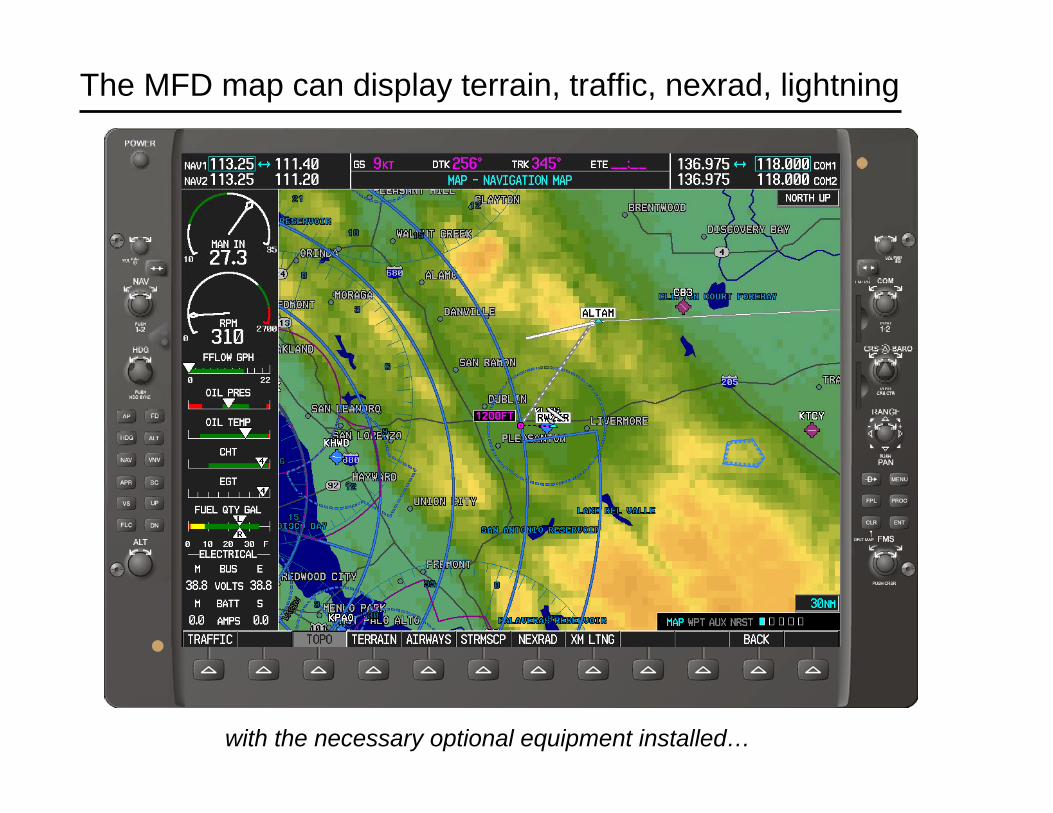
The MFD map can display terrain, traffic, nexrad, lightning
with the necessary optional equipment installed…

The MFD is showing XM NEXRAD data.
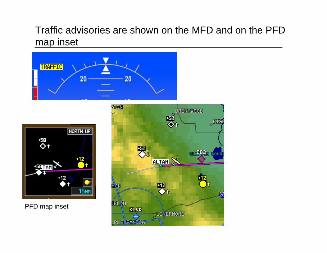
Traffic advisories are shown on the MFD and on the PFD map inset
PFD map inset

I highly recommend this book…

The King School is a good overview -- but is $249
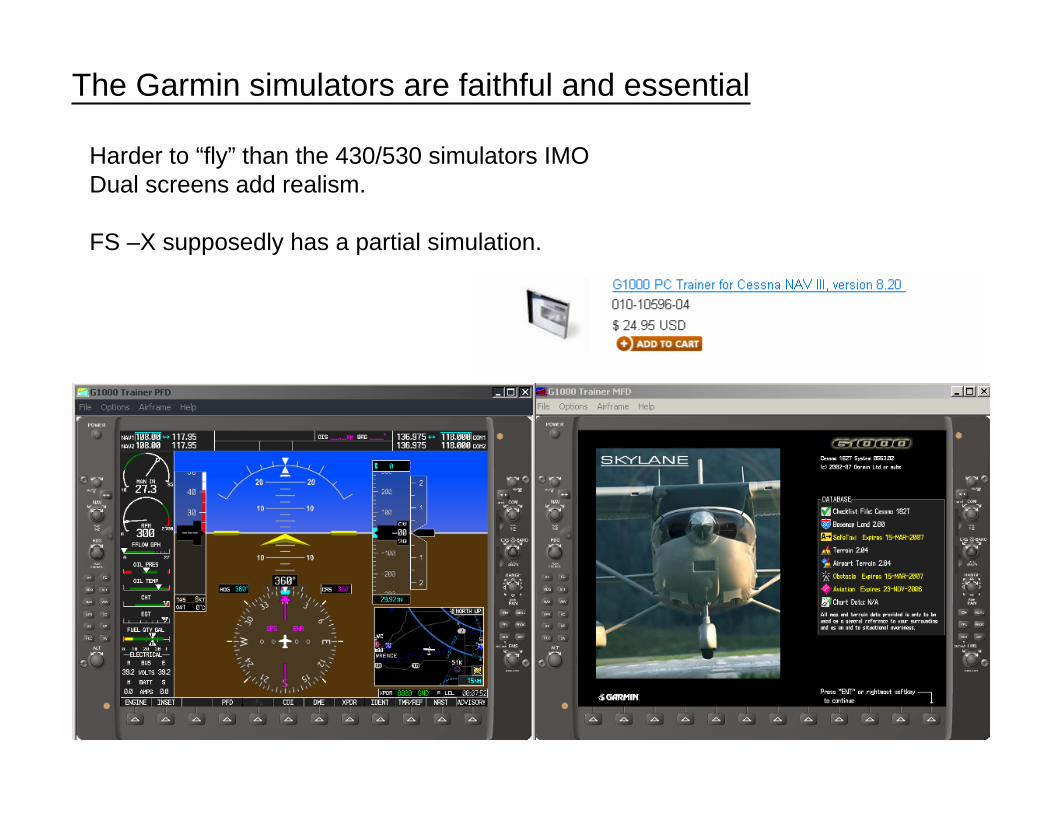
The Garmin simulators are faithful and essential
Harder to “fly” than the 430/530 simulators IMODual screens add realism.
FS –X supposedly has a partial simulation.
If you’ve not flown a glass panel, give it a try.
• I found the instrument display intuitive – easy to transition to.
• Practice with the simulator was greatly rewarded.
• The GPS is easy if you know the 430/530.
• Keep looking out the window!!