Fluid Mechanics Series - Armfield
30
Fluid Mechanics Series The Armfield F series is known worldwide for its durability, reliability and easy operation. This family of products covers all of the relevant aspects of Fluid Mechanics: Fluid Dynamics, Hydrostatics, Open and Closed Channel Flow as well as Rotodynamic Machines. The latest upgrade of the range includes a Digital Hydraulic Bench, a redesigned Series and Parallel Pumps accessory and updated modules such as the Pascal’s Apparatus and the Cavitation Demonstration. The series is also now complemented with the exclusive Armfield F1-aBASIC software supplied along with both versions of the Basic Hydraulic Bench. This facilitates the laboratory sessions for students and instructors by enabling manual datalogging and permitting the users to focus on the understanding of the principles of the phenomena being simulated in the Fluid Mechanics Laboratory. F1a-Basic SOFTWARE INCLUDED AS STANDARD F SERIES USA office - email: [email protected] tel: +1 (609) 208-2800 (USA only) UK office - email: [email protected] tel: +44 (0)1425 478781 (for ROW) Web: armfield.co.uk ©2021 Armfield Ltd. All Rights Reserved Part of Judges Scientific PLC ISO 9001:2015 Complete Fluid Mechanics Laboratory – F1 F SERIES: BASIC FLUID MECHANICS
-
Upload
khangminh22 -
Category
Documents
-
view
2 -
download
0
Transcript of Fluid Mechanics Series - Armfield

Fluid Mechanics Series
The Armfield F series is known worldwide for its durability, reliability and easy operation. This family of products covers all of the relevant aspects of Fluid Mechanics: Fluid Dynamics, Hydrostatics, Open and Closed Channel Flow as well as Rotodynamic Machines.
The latest upgrade of the range includes a Digital Hydraulic Bench, a redesigned Series and Parallel Pumps accessory and updated modules such as the Pascal’s Apparatus and the Cavitation Demonstration.
The series is also now complemented with the exclusive Armfield F1-aBASIC software supplied along with both versions of the Basic Hydraulic Bench. This facilitates the laboratory sessions for students and instructors by enabling manual datalogging and permitting the users to focus on the understanding of the principles of the phenomena being simulated in the Fluid Mechanics Laboratory.
F1a-Basic SOFTWARE
INCLUDED AS STANDARD
F SERIES
USA office - email: [email protected]: +1 (609) 208-2800 (USA only)
UK office - email: [email protected] tel: +44 (0)1425 478781 (for ROW)
Web: armfield.co.uk©2021 Armfield Ltd. All Rights Reserved Part of Judges Scientific PLC
ISO 9001:2015
Complete Fluid Mechanics Laboratory – F1F SERIES: BASIC FLUID MECHANICS

armfield.co.ukWe reserve the right to amend these specif ications without prior notice. E&OE © 2022 Armfield Ltd. All Rights Reserved
UK office - email: [email protected] tel: +44 (0) 1425 478781 (for ROW)USA office - email: [email protected] tel: +1 (609) 208-2800 (USA only)
Overall dimensionsLength 1.13m
Width 0.73m
Height 1.0m
Packed and crated shipping specifications
Volume 1.5m3
Gross weight 160kg
Technical specificationsPump
(using volumetric tank) (using appropriate accessory)
SubmersibleMax head: 8.3m H2OMax flow: 80 litres/minMax flow: 100 litres/min
Motor rating 0.25kWSump tank capacity 250 litresHigh flow volumetric tank 40 litresLow flow volumetric tank 6 litresHeight of working surface 1m above floor level
u F1-10-A u F1-10-B u F1-10-G
u F1-10-2-A/-B/-G u F1-10-2-A/-B/-G u F1-10-2-A/-B/-G
u F1-10-1 Digital Flow Meter for F1-10 Hydraulics Bench
Ordering codes
1Ph
F1a-Basic SOFTWARE
INCLUDED AS STANDARDF
SERIES
Issue: 2 Applications
URL: http://www.armfield.co.uk/f1 CE IPChE ME
Complete Fluid Mechanics Laboratory – F1F SERIES: BASIC FLUID MECHANICS
The F1-10 unit is a portable and self-contained service module providing a controlled flow of water to a range of optional accessories. It is supplied as standard with the Fluid Mechanics F1-aBASIC SoftwareThis mobile bench is constructed from lightweight corrosion-resistant plastic and incorporates an open channel with side channels to support the accessories on test. The hydraulics bench includes a volumetric measuring tank stepped to accommodate low or high flow rates and a stilling baffle to reduce turbulence. A remote sight tube with scale gives an instantaneous indication of water level. The bench additionally includes a quick-release pipe connector situated in the benchtop enabling rapid exchange of accessories without the need for hand tools, a measuring cylinder for measurement of very small flow rates, stopwatch and a copy of Armfield’s F1-aBASIC educational software. The F1-10 hydraulics bench can be supplied with either a factory fitted electronic flow meter with digital display or an optional inline digital flow meter that can be added in line to the experiment on test at any time.
Optional factory fitted electronic flow meter
Hydraulics Bench - F1-10
Electrical supply: Basic Hydraulics Bench:
u F1-10-A 220-240V / 1ph / 50Hz @ 10 amp u F1-10-B 110-120V / 1ph / 60Hz @ 20 amp u F1-10-G 220V / 1ph / 60Hz @ 10 amp
Digital Hydraulics Bench (with digital flow meter): u F1-10-2-A 220-240V / 1ph / 50Hz @ 10 amp u F1-10-2-B 110-120V / 1ph / 60Hz @ 20 amp u F1-10-2-G 220V / 1ph / 60Hz @ 10 amp
Water: Fill with clean water. No permanent connection required.
Requirements Scale
COLD HOT
PC IFD 7
FM 6X
1Ph
COLD USB
oil DRAIN
COLD HOT
PC IFD 7
FM 6X
1Ph
COLD USB
oil HEARING PROTECTION
EXTRACTOR
PC IFD 7
FM 6X
1Ph
COLD USB
oil DRAIN
HEARING PROTECTION
EXTRACTOR GENERATOR
STEAMSTEAM
GENERATOR
STEAM
DRAIN
USB USB I/O
USB
3Ph
FM 6X
FM 6X
COLD
GRAVEL
DYE
COMP. AIR
GENERATOR
STEAM
FILTRATION CHILLER
PC
1Ph
IFD 7
F 1-10
HOT
DRAIN
SAND
OIL
EXTRACTOR
COMP. AIR
SOUND PROOFING
COLD
F1-10_New_Layout_v2b.indd 1F1-10_New_Layout_v2b.indd 1 08/02/2022 17:19:5508/02/2022 17:19:55

armfield.co.ukWe reserve the right to amend these specif ications without prior notice. E&OE © 2022 Armfield Ltd. All Rights Reserved
UK office - email: [email protected] tel: +44 (0) 1425 478781 (for ROW)USA office - email: [email protected] tel: +1 (609) 208-2800 (USA only)Service and maintenance support: armfieldassist.com
Armfield’s F1-aBASIC software is now included as standard with either of the hydraulic benches. The Armfield software is a powerful manual data entry learning package which enhances the educational content and understanding of Armfield’s F1 Fluid Mechanics accessories that utilise either of the F1-10 Hydraulics benches.
The software allows the user to manually input data from primary instrumentation and offers a powerful tool for displaying and processing the results.
Software additionally includes the electronic version of the manual for all the modules on test.
Some of the major features include:
Mimic Diagram - a pictorial representation of the equipment with fields to enter measurements from the equipment which displays any calculated variables directly in engineering units.
Tabular Display - As the data is entered, it is stored in a spreadsheet format. The table also contains columns for the calculated values.
Graphical Display - When several samples have been recorded, they can be viewed in graphical format. Powerful and flexible graph plotting tools are available in the software allowing the user full choice over what is displayed.
armfield.co.ukWe reserve the right to amend these specif ications without prior notice. E&OE © 2022 Armfield Ltd. All Rights Reserved
UK office - email: [email protected] tel: +44 (0) 1425 478781 (for ROW)USA office - email: [email protected] tel: +1 (609) 208-2800 (USA only)
Overall dimensionsLength 1.13m
Width 0.73m
Height 1.0m
Packed and crated shipping specifications
Volume 1.5m3
Gross weight 160kg
Technical specificationsPump
(using volumetric tank) (using appropriate accessory)
SubmersibleMax head: 8.3m H2OMax flow: 80 litres/minMax flow: 100 litres/min
Motor rating 0.25kWSump tank capacity 250 litresHigh flow volumetric tank 40 litresLow flow volumetric tank 6 litresHeight of working surface 1m above floor level
u F1-10-A u F1-10-B u F1-10-G
u F1-10-2-A/-B/-G u F1-10-2-A/-B/-G u F1-10-2-A/-B/-G
u F1-10-1 Digital Flow Meter for F1-10 Hydraulics Bench
Ordering codes
1Ph
F1a-Basic SOFTWARE
INCLUDED AS STANDARDF
SERIES
Issue: 2 Applications
URL: http://www.armfield.co.uk/f1 CE IPChE ME
Complete Fluid Mechanics Laboratory – F1F SERIES: BASIC FLUID MECHANICS
The F1-10 unit is a portable and self-contained service module providing a controlled flow of water to a range of optional accessories. It is supplied as standard with the Fluid Mechanics F1-aBASIC SoftwareThis mobile bench is constructed from lightweight corrosion-resistant plastic and incorporates an open channel with side channels to support the accessories on test. The hydraulics bench includes a volumetric measuring tank stepped to accommodate low or high flow rates and a stilling baffle to reduce turbulence. A remote sight tube with scale gives an instantaneous indication of water level. The bench additionally includes a quick-release pipe connector situated in the benchtop enabling rapid exchange of accessories without the need for hand tools, a measuring cylinder for measurement of very small flow rates, stopwatch and a copy of Armfield’s F1-aBASIC educational software. The F1-10 hydraulics bench can be supplied with either a factory fitted electronic flow meter with digital display or an optional inline digital flow meter that can be added in line to the experiment on test at any time.
Optional factory fitted electronic flow meter
Hydraulics Bench - F1-10
Electrical supply: Basic Hydraulics Bench:
u F1-10-A 220-240V / 1ph / 50Hz @ 10 amp u F1-10-B 110-120V / 1ph / 60Hz @ 20 amp u F1-10-G 220V / 1ph / 60Hz @ 10 amp
Digital Hydraulics Bench (with digital flow meter): u F1-10-2-A 220-240V / 1ph / 50Hz @ 10 amp u F1-10-2-B 110-120V / 1ph / 60Hz @ 20 amp u F1-10-2-G 220V / 1ph / 60Hz @ 10 amp
Water: Fill with clean water. No permanent connection required.
Requirements Scale
COLD HOT
PC IFD 7
FM 6X
1Ph
COLD USB
oil DRAIN
COLD HOT
PC IFD 7
FM 6X
1Ph
COLD USB
oil HEARING PROTECTION
EXTRACTOR
PC IFD 7
FM 6X
1Ph
COLD USB
oil DRAIN
HEARING PROTECTION
EXTRACTOR GENERATOR
STEAMSTEAM
GENERATOR
STEAM
DRAIN
USB USB I/O
USB
3Ph
FM 6X
FM 6X
COLD
GRAVEL
DYE
COMP. AIR
GENERATOR
STEAM
FILTRATION CHILLER
PC
1Ph
IFD 7
F 1-10
HOT
DRAIN
SAND
OIL
EXTRACTOR
COMP. AIR
SOUND PROOFING
COLD
F1-10_New_Layout_v2b.indd 1F1-10_New_Layout_v2b.indd 1 08/02/2022 17:19:5508/02/2022 17:19:55
F SERIES
Issue: 2 Applications
URL: http://www.armfield.co.uk/f1 CE IPChE ME
armSOFT Software F1-aBASIC
Impact of a Jet F1-16-MKII
Complete Fluid Mechanics Laboratory – F1F SERIES: BASIC FLUID MECHANICS
Mimic Diagram
Graphical Display
Tabular Display
SOFTWARE INCLUDED WITH
ALL F1-10 BENCH’S AS STANDARD

Experimental content u To calibrate a Bourdon type pressure gauge and to determine the
gauge errors u To determine the measurement errors in the reference pressure
source used for calibration
Dead Weight Calibrator - F1-11
120
100
80
60
40
20
00 20 40 60 80 100 120
Calib
rate
d pr
essu
re k
N/m
2
Indicated pressure kN/m
3
This calibrator functions under the same principle adopted in calibrating industrial pressure gauges.
F1-11 shown with the F9092 bench
Description
The Dead Weight Calibrator consists of a precision-machined piston and cylinder assembly mounted on levelling screws.
A Bourdon gauge is supplied for calibration. The weights supplied are added to the upper end of the piston rod which is rotated to minimise friction effects.
The gauge is thus subject to known pressures which may be compared with the gauge readings and an error curve drawn.
Overall dimensions
Length 0.25m
Width 0.125m
Height 0.50m
Technical specifications
Pressure gauge Bourdon tube
range 0 to 200 kN/m2 (kPa)
Area of piston 244.8 x 10⁻⁶ m2
Mass of piston 0.5kg
Ancillary masses 2x 0.5kg, 1.0kg and 2.5kg
u F1-11
Ordering codes
SOFTWARE INCLUDED WITH
ALL F1-10 BENCH’S AS STANDARDF
SERIES
armfield.co.ukWe reserve the right to amend these specif ications without prior notice. E&OE © 2022 Armfield Ltd. All Rights Reserved
UK office - email: [email protected] tel: +44 (0) 1425 478781 (for ROW)USA office - email: [email protected] tel: +1 (609) 208-2800 (USA only)
Issue: 2 Applications
URL: http://www.armfield.co.uk/f1 CE IPChE ME
Complete Fluid Mechanics Laboratory – F1F SERIES: BASIC FLUID MECHANICS
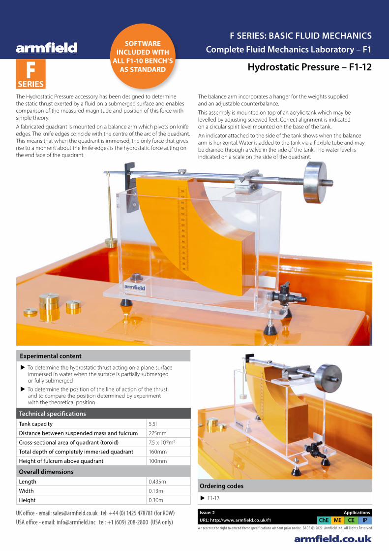
Hydrostatic Pressure – F1-12
Experimental content
u To determine the hydrostatic thrust acting on a plane surface immersed in water when the surface is partially submerged or fully submerged
u To determine the position of the line of action of the thrust and to compare the position determined by experiment with the theoretical position
The Hydrostatic Pressure accessory has been designed to determine the static thrust exerted by a fluid on a submerged surface and enables comparison of the measured magnitude and position of this force with simple theory.
A fabricated quadrant is mounted on a balance arm which pivots on knife edges. The knife edges coincide with the centre of the arc of the quadrant. This means that when the quadrant is immersed, the only force that gives rise to a moment about the knife edges is the hydrostatic force acting on the end face of the quadrant.
The balance arm incorporates a hanger for the weights supplied and an adjustable counterbalance.
This assembly is mounted on top of an acrylic tank which may be levelled by adjusting screwed feet. Correct alignment is indicated on a circular spirit level mounted on the base of the tank.
An indicator attached to the side of the tank shows when the balance arm is horizontal. Water is added to the tank via a flexible tube and may be drained through a valve in the side of the tank. The water level is indicated on a scale on the side of the quadrant.
Overall dimensionsLength 0.435m
Width 0.13m
Height 0.30m
Technical specificationsTank capacity 5.5l
Distance between suspended mass and fulcrum 275mm
Cross-sectional area of quadrant (toroid) 7.5 x 10⁻³m2
Total depth of completely immersed quadrant 160mm
Height of fulcrum above quadrant 100mm
u F1-12
Ordering codes
SOFTWARE INCLUDED WITH
ALL F1-10 BENCH’S AS STANDARDF
SERIES
armfield.co.ukWe reserve the right to amend these specif ications without prior notice. E&OE © 2022 Armfield Ltd. All Rights Reserved
UK office - email: [email protected] tel: +44 (0) 1425 478781 (for ROW)USA office - email: [email protected] tel: +1 (609) 208-2800 (USA only)Service and maintenance support: armfieldassist.com
SOFTWARE INCLUDED WITH
ALL F1-10 BENCH’S AS STANDARDF
SERIES
Issue: 2 Applications
URL: http://www.armfield.co.uk/f1 CE IPChE ME
Complete Fluid Mechanics Laboratory – F1F SERIES: BASIC FLUID MECHANICS
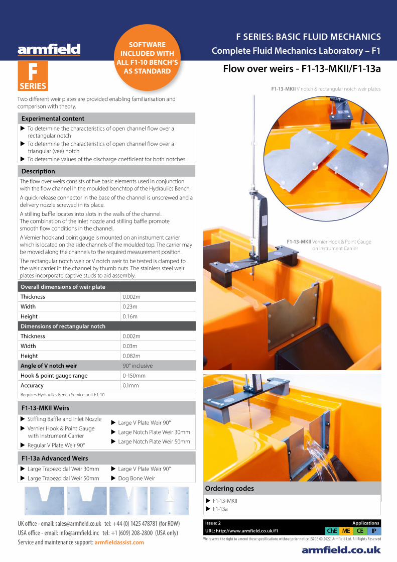
Flow over weirs - F1-13-MKII/F1-13a
F1-13-MKII V notch & rectangular notch weir plates
F1-13-MKII Vernier Hook & Point Gauge on Instrument Carrier
u F1-13-MKII u F1-13a
Ordering codes
Experimental content u To determine the characteristics of open channel flow over a
rectangular notch u To determine the characteristics of open channel flow over a
triangular (vee) notch u To determine values of the discharge coefficient for both notches
DescriptionThe flow over weirs consists of five basic elements used in conjunction with the flow channel in the moulded benchtop of the Hydraulics Bench.
A quick-release connector in the base of the channel is unscrewed and a delivery nozzle screwed in its place.
A stilling baffle locates into slots in the walls of the channel. The combination of the inlet nozzle and stilling baffle promote smooth flow conditions in the channel.
A Vernier hook and point gauge is mounted on an instrument carrier which is located on the side channels of the moulded top. The carrier may be moved along the channels to the required measurement position.
The rectangular notch weir or V notch weir to be tested is clamped to the weir carrier in the channel by thumb nuts. The stainless steel weir plates incorporate captive studs to aid assembly.
F1-13a Advanced Weirs
u Large Trapezoidal Weir 30mm
u Large Trapezoidal Weir 50mm
u Large V Plate Weir 90°
u Dog Bone Weir
F1-13-MKII Weirs
u Stiffling Baffle and Inlet Nozzle
u Vernier Hook & Point Gauge with Instrument Carrier
u Regular V Plate Weir 90°
u Large V Plate Weir 90°
u Large Notch Plate Weir 30mm
u Large Notch Plate Weir 50mm
Overall dimensions of weir plate
Thickness 0.002m
Width 0.23m
Height 0.16m
Dimensions of rectangular notch
Thickness 0.002m
Width 0.03m
Height 0.082m
Angle of V notch weir 90° inclusive
Hook & point gauge range 0-150mm
Accuracy 0.1mmRequires Hydraulics Bench Service unit F1-10
Two different weir plates are provided enabling familiarisation and comparison with theory.

armfield.co.ukWe reserve the right to amend these specif ications without prior notice. E&OE © 2022 Armfield Ltd. All Rights Reserved
UK office - email: [email protected] tel: +44 (0) 1425 478781 (for ROW)USA office - email: [email protected] tel: +1 (609) 208-2800 (USA only)Service and maintenance support: armfieldassist.com
SOFTWARE INCLUDED WITH
ALL F1-10 BENCH’S AS STANDARDF
SERIES
Issue: 2 Applications
URL: http://www.armfield.co.uk/f1 CE IPChE ME
Complete Fluid Mechanics Laboratory – F1F SERIES: BASIC FLUID MECHANICS
Flow over weirs - F1-13-MKII/F1-13a
F1-13-MKII V notch & rectangular notch weir plates
F1-13-MKII Vernier Hook & Point Gauge on Instrument Carrier
u F1-13-MKII u F1-13a
Ordering codes
Experimental content u To determine the characteristics of open channel flow over a
rectangular notch u To determine the characteristics of open channel flow over a
triangular (vee) notch u To determine values of the discharge coefficient for both notches
DescriptionThe flow over weirs consists of five basic elements used in conjunction with the flow channel in the moulded benchtop of the Hydraulics Bench.
A quick-release connector in the base of the channel is unscrewed and a delivery nozzle screwed in its place.
A stilling baffle locates into slots in the walls of the channel. The combination of the inlet nozzle and stilling baffle promote smooth flow conditions in the channel.
A Vernier hook and point gauge is mounted on an instrument carrier which is located on the side channels of the moulded top. The carrier may be moved along the channels to the required measurement position.
The rectangular notch weir or V notch weir to be tested is clamped to the weir carrier in the channel by thumb nuts. The stainless steel weir plates incorporate captive studs to aid assembly.
F1-13a Advanced Weirs
u Large Trapezoidal Weir 30mm
u Large Trapezoidal Weir 50mm
u Large V Plate Weir 90°
u Dog Bone Weir
F1-13-MKII Weirs
u Stiffling Baffle and Inlet Nozzle
u Vernier Hook & Point Gauge with Instrument Carrier
u Regular V Plate Weir 90°
u Large V Plate Weir 90°
u Large Notch Plate Weir 30mm
u Large Notch Plate Weir 50mm
Overall dimensions of weir plate
Thickness 0.002m
Width 0.23m
Height 0.16m
Dimensions of rectangular notch
Thickness 0.002m
Width 0.03m
Height 0.082m
Angle of V notch weir 90° inclusive
Hook & point gauge range 0-150mm
Accuracy 0.1mmRequires Hydraulics Bench Service unit F1-10
Two different weir plates are provided enabling familiarisation and comparison with theory.
Complete Fluid Mechanics Laboratory – F1F SERIES: BASIC FLUID MECHANICS
SOFTWARE INCLUDED WITH
ALL F1-10 BENCH’S AS STANDARDF
SERIES
armfield.co.ukWe reserve the right to amend these specif ications without prior notice. E&OE © 2022 Armfield Ltd. All Rights Reserved
UK office - email: [email protected] tel: +44 (0) 1425 478781 (for ROW)USA office - email: [email protected] tel: +1 (609) 208-2800 (USA only)
Issue: 2 Applications
URL: http://www.armfield.co.uk/f1 CE IPChE ME
Metacentric Height - F1-14
This equipment enables a thorough investigation of the factors affecting the stability of a floating body.
Experimental content
u Determining the centre of gravity of the pontoon u Determining the metacentric height and from this the position
of the metacentre for the pontoon u Varying the metacentric height with angle of heel
DescriptionThe position of the metacentre can be varied to produce stable and unstable equilibrium.
The equipment consists of a plastic rectangular floating pontoon where the centre of gravity can be varied by an adjustable weight which slides and can be clamped in any position on a vertical mast.
A single plumb bob is suspended from the mast which indicates the angle of heel on a calibrated scale.
A weight with lateral adjustment enables the degree of heel to be varied and hence the stability of the pontoon determined.
The equipment does not require a separate water tank as it may be used on the hydraulics bench by filling the volumetric tank.
F1-14 Calibrated scale
Technical specificationsOverall dimensions:
Length 0.35m
Width 0.20m
Height 0.475m
Max angle of heel ±13°
Corresponding linear dimension ±90mm
u F1-14
Ordering codes

armfield.co.ukWe reserve the right to amend these specif ications without prior notice. E&OE © 2022 Armfield Ltd. All Rights Reserved
UK office - email: [email protected] tel: +44 (0) 1425 478781 (for ROW)USA office - email: [email protected] tel: +1 (609) 208-2800 (USA only)
Issue: 2 Applications
URL: http://www.armfield.co.uk/f1 CE IPChE ME
Bernoulli’s Theorem Demonstration - F1-15
This accessory illustrates the circumstances to which Bernoulli’s Theorem may be applied.
It also explains why in other circumstances the theorem gives an inadequate description of the fluid behaviour.
Experimental content u To investigate the validity of the Bernoulli equation when applied
to the steady flow of water in a converging, or, a diverging duct u Conservation of energy divergent/convergent pipe flow u Effect of friction loss on Bernoulli equation u Recording the pressure curve in a Venturi nozzle u Recording the velocity curve in a Venturi nozzle u Determining the flow coefficient
Description
The test section consists of a classical Venturi machined in clear acrylic.
A series of wall tappings enable measurement of the static pressure distribution along the converging and diverging duct. A total head tube is provided to traverse along the centre line of the test section.
These tappings are connected to a manometer bank incorporating a manifold with an air bleed valve.
Pressurisation of the manometers is facilitated by a hand pump. The test section is arranged so that the characteristics of flow through both a converging and diverging section can be studied.
Water is fed through a hose connector and is controlled by a flow regulator valve at the outlet of the test section.
The Venturi can be demonstrated as a means of flow measurement and the discharge coefficient can be determined.
F1-15: Manometer bank
F1-15: Venturi tube
Overall dimensionsLength 0.55mWidth 0.25mHeight 0.60m
Technical specifications (Requires Hydraulics Bench Service unit F1-10/F1-10-2)
Manometer range 0-300mm
Number of manometer tubes 8
Throat diameter 10.0mm
Upstream diameter 25.0mm
Upstream taper 14°
Downstream taper 21°
u F1-15
Ordering codes
F SERIES
Complete Fluid Mechanics Laboratory – F1F SERIES: BASIC FLUID MECHANICS
SOFTWARE INCLUDED WITH
ALL F1-10 BENCH’S AS STANDARD
F SERIES
armfield.co.ukWe reserve the right to amend these specif ications without prior notice. E&OE © 2022 Armfield Ltd. All Rights Reserved
UK office - email: [email protected] tel: +44 (0) 1425 478781 (for ROW)USA office - email: [email protected] tel: +1 (609) 208-2800 (USA only)
Issue: 1 Applications
URL: http://www.armfield.co.uk/f1 CE IPChE ME
Complete Fluid Mechanics Laboratory – F1F SERIES: BASIC FLUID MECHANICS
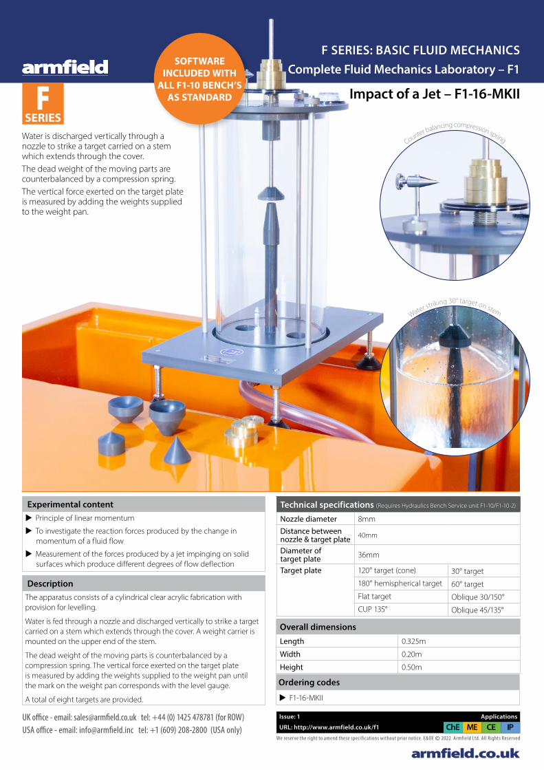
Water is discharged vertically through a nozzle to strike a target carried on a stem which extends through the cover. The dead weight of the moving parts are counterbalanced by a compression spring.The vertical force exerted on the target plate is measured by adding the weights supplied to the weight pan.
Experimental content u Principle of linear momentum
u To investigate the reaction forces produced by the change in momentum of a fluid flow
u Measurement of the forces produced by a jet impinging on solid surfaces which produce different degrees of flow deflection
DescriptionThe apparatus consists of a cylindrical clear acrylic fabrication with provision for levelling.
Water is fed through a nozzle and discharged vertically to strike a target carried on a stem which extends through the cover. A weight carrier is mounted on the upper end of the stem.
The dead weight of the moving parts is counterbalanced by a compression spring. The vertical force exerted on the target plate is measured by adding the weights supplied to the weight pan until the mark on the weight pan corresponds with the level gauge.
A total of eight targets are provided.
Counter balancing compression spring
Water striking 30° target on stem
Overall dimensionsLength 0.325m
Width 0.20m
Height 0.50m
Technical specifications (Requires Hydraulics Bench Service unit F1-10/F1-10-2)
Nozzle diameter 8mmDistance between nozzle & target plate 40mm
Diameter of target plate 36mm
Target plate 120° target (cone) 30° target180° hemispherical target 60° targetFlat target Oblique 30/150°CUP 135° Oblique 45/135°
u F1-16-MKII
Ordering codes
Impact of a Jet – F1-16-MKII
SOFTWARE INCLUDED WITH
ALL F1-10 BENCH’S AS STANDARD

Orifice and Free Jet Flow - F1-17F SERIES
armfield.co.ukWe reserve the right to amend these specif ications without prior notice. E&OE © 2022 Armfield Ltd. All Rights Reserved
UK office - email: [email protected] tel: +44 (0) 1425 478781 (for ROW)USA office - email: [email protected] tel: +1 (609) 208-2800 (USA only)
Issue: 2 Applications
URL: http://www.armfield.co.uk/f1 CE IPChE ME
Complete Fluid Mechanics Laboratory – F1F SERIES: BASIC FLUID MECHANICS
F1-17: Free Jet Flow Orifice
This equipment permits calibration of two orifices of differing diameter and enables the trajectory of the jet to be plotted.
A constant head tank is maintained with water supplied from the hydraulics bench.
The orifice (3mm or 6mm) is installed at the base of this tank ensuring a flush inside surface.
The jet trajectory is mapped using 8-point gauges to determine the discharge coefficient.
DescriptionThe Orifice & Free Jet Flow accessory incorporates a constant head tank fed with water from the hydraulics bench. The orifice is installed at the base of this tank by means of a special wall fitting which provides a flush inside surface.
The head is maintained at a constant value by an adjustable overflow pipe and is indicated by a level scale. A series of adjustable probes enable the path followed by the jet to be ascertained.
Adjustable feet permit levelling.
u Establishing the coefficient of velocity for a small orifice u Finding the coefficient of discharge for a small orifice with flow
under constant head and flow under varying head u Comparing the measured trajectory of a jet with that predicted
by simple theory of mechanics u Effect of tank level on jet outlet velocity
Experimental content
Overall dimensionsLength 0.67m
Width 0.33m
Height 0.60m
Technical specificationsOrifice diameters 3.0mm and 6.0mm
Jet trajectory probes 8Max constant head 410mm
Requires hydraulics bench service unit F1-10/F1-10-2
u F1-17
Ordering codes
SOFTWARE INCLUDED WITH
ALL F1-10 BENCH’S AS STANDARD
armfield.co.ukWe reserve the right to amend these specif ications without prior notice. E&OE © 2022 Armfield Ltd. All Rights Reserved
UK office - email: [email protected] tel: +44 (0) 1425 478781 (for ROW)USA office - email: [email protected] tel: +1 (609) 208-2800 (USA only)
Issue: 2 Applications
URL: http://www.armfield.co.uk/f1 CE IPChE ME
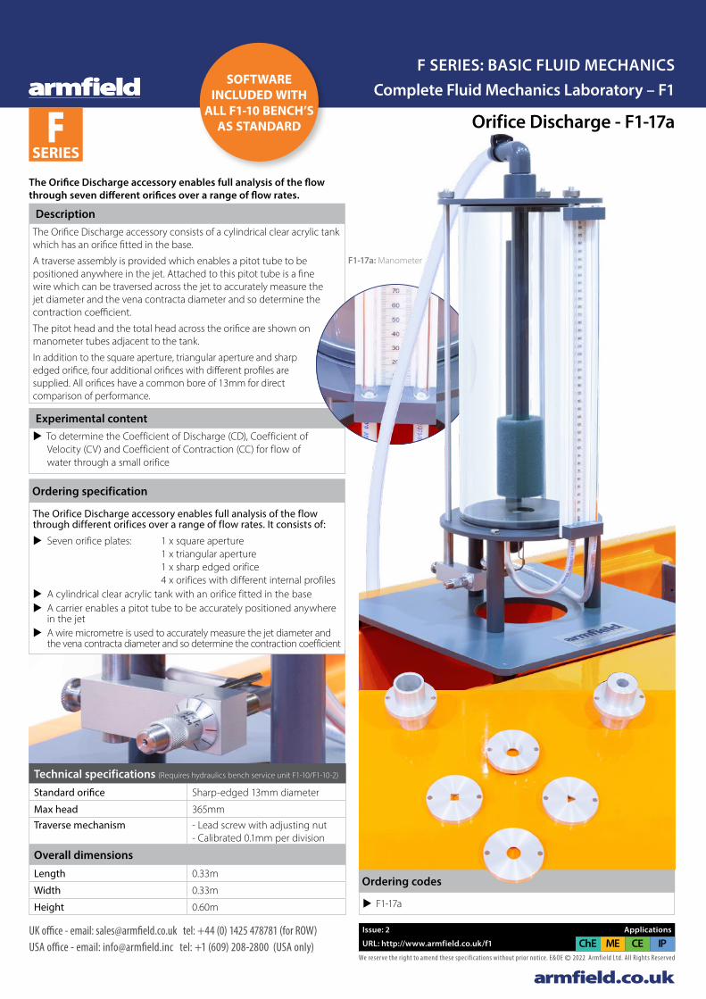
Orifice Discharge - F1-17a
The Orifice Discharge accessory enables full analysis of the flow through different orifices over a range of flow rates. It consists of:
u Seven orifice plates: 1 x square aperture 1 x triangular aperture 1 x sharp edged orifice 4 x orifices with different internal profiles
u A cylindrical clear acrylic tank with an orifice fitted in the base u A carrier enables a pitot tube to be accurately positioned anywhere
in the jet u A wire micrometre is used to accurately measure the jet diameter and
the vena contracta diameter and so determine the contraction coefficient
Ordering specification
The Orifice Discharge accessory enables full analysis of the flow through seven different orifices over a range of flow rates.
Experimental content u To determine the Coefficient of Discharge (CD), Coefficient of
Velocity (CV) and Coefficient of Contraction (CC) for flow of water through a small orifice
DescriptionThe Orifice Discharge accessory consists of a cylindrical clear acrylic tank which has an orifice fitted in the base.
A traverse assembly is provided which enables a pitot tube to be positioned anywhere in the jet. Attached to this pitot tube is a fine wire which can be traversed across the jet to accurately measure the jet diameter and the vena contracta diameter and so determine the contraction coefficient.
The pitot head and the total head across the orifice are shown on manometer tubes adjacent to the tank.
In addition to the square aperture, triangular aperture and sharp edged orifice, four additional orifices with different profiles are supplied. All orifices have a common bore of 13mm for direct comparison of performance.
F1-17a: Orifice plates
Ordering codes
u F1-17a
Overall dimensionsLength 0.33m
Width 0.33m
Height 0.60m
Technical specifications (Requires hydraulics bench service unit F1-10/F1-10-2)
Standard orifice Sharp-edged 13mm diameter
Max head 365mmTraverse mechanism - Lead screw with adjusting nut
- Calibrated 0.1mm per division
F1-17a: Manometer
F SERIES
Complete Fluid Mechanics Laboratory – F1F SERIES: BASIC FLUID MECHANICS
SOFTWARE INCLUDED WITH
ALL F1-10 BENCH’S AS STANDARD
Armfield F1-17a DataSheet v2b.indd 1Armfield F1-17a DataSheet v2b.indd 1 24/01/2022 12:23:1624/01/2022 12:23:16
Energy Losses in Pipes - F1-18F SERIES
armfield.co.ukWe reserve the right to amend these specif ications without prior notice. E&OE © 2022 Armfield Ltd. All Rights Reserved
UK office - email: [email protected] tel: +44 (0) 1425 478781 (for ROW)USA office - email: [email protected] tel: +1 (609) 208-2800 (USA only)
Issue: 2 Applications
URL: http://www.armfield.co.uk/f1 CE IPChE ME
Complete Fluid Mechanics Laboratory – F1F SERIES: BASIC FLUID MECHANICS
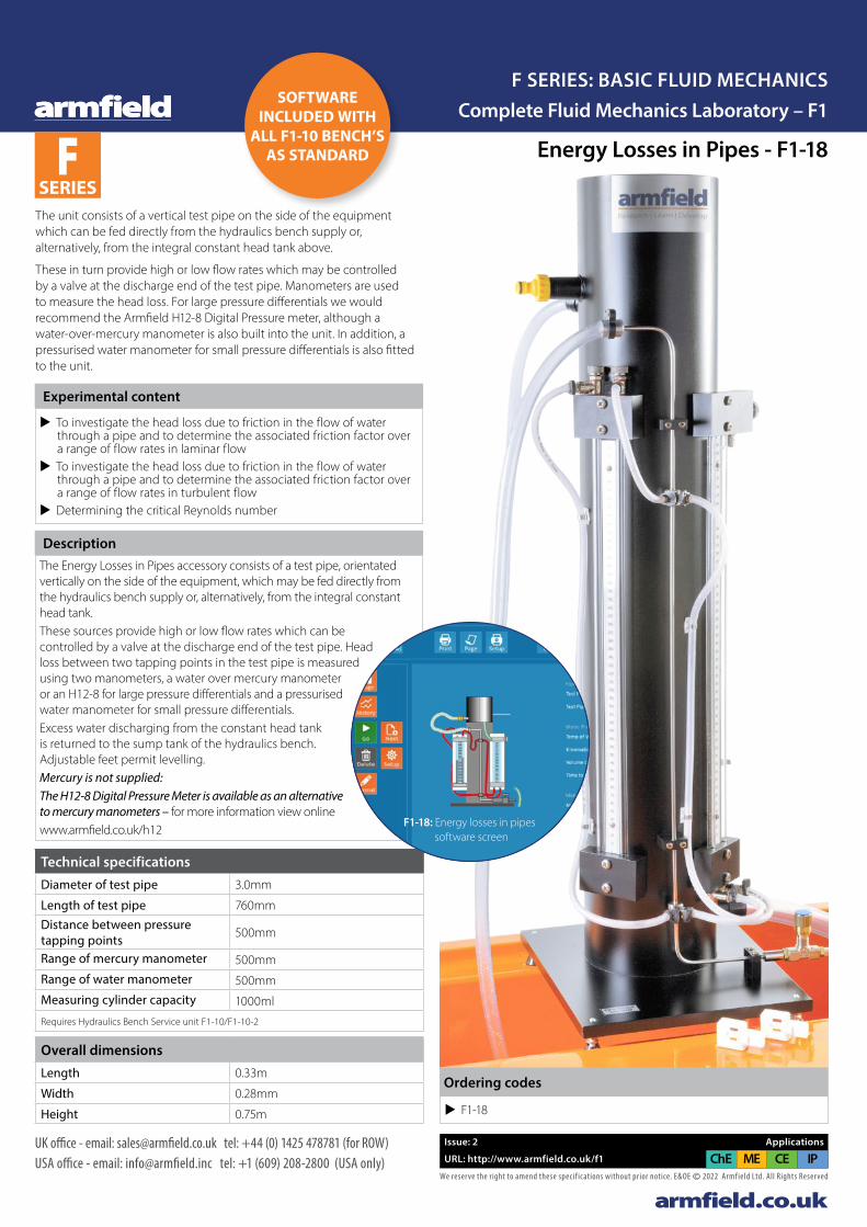
The unit consists of a vertical test pipe on the side of the equipment which can be fed directly from the hydraulics bench supply or, alternatively, from the integral constant head tank above.
These in turn provide high or low flow rates which may be controlled by a valve at the discharge end of the test pipe. Manometers are used to measure the head loss. For large pressure differentials we would recommend the Armfield H12-8 Digital Pressure meter, although a water-over-mercury manometer is also built into the unit. In addition, a pressurised water manometer for small pressure differentials is also fitted to the unit.
Experimental content
u To investigate the head loss due to friction in the flow of water through a pipe and to determine the associated friction factor over a range of flow rates in laminar flow
u To investigate the head loss due to friction in the flow of water through a pipe and to determine the associated friction factor over a range of flow rates in turbulent flow
u Determining the critical Reynolds number
DescriptionThe Energy Losses in Pipes accessory consists of a test pipe, orientated vertically on the side of the equipment, which may be fed directly from the hydraulics bench supply or, alternatively, from the integral constant head tank.These sources provide high or low flow rates which can be controlled by a valve at the discharge end of the test pipe. Head loss between two tapping points in the test pipe is measured using two manometers, a water over mercury manometer or an H12-8 for large pressure differentials and a pressurised water manometer for small pressure differentials.Excess water discharging from the constant head tank is returned to the sump tank of the hydraulics bench. Adjustable feet permit levelling.Mercury is not supplied:The H12-8 Digital Pressure Meter is available as an alternative to mercury manometers – for more information view onlinewww.armfield.co.uk/h12
Overall dimensionsLength 0.33m
Width 0.28mm
Height 0.75m
Technical specificationsDiameter of test pipe 3.0mm
Length of test pipe 760mmDistance between pressure tapping points 500mm
Range of mercury manometer 500mmRange of water manometer 500mmMeasuring cylinder capacity 1000ml
Requires Hydraulics Bench Service unit F1-10/F1-10-2
u F1-18
Ordering codes
F1-18: Energy losses in pipes software screen
SOFTWARE INCLUDED WITH
ALL F1-10 BENCH’S AS STANDARD
armfield.co.ukWe reserve the right to amend these specif ications without prior notice. E&OE © 2022 Armfield Ltd. All Rights Reserved
UK office - email: [email protected] tel: +44 (0) 1425 478781 (for ROW)USA office - email: [email protected] tel: +1 (609) 208-2800 (USA only)
Issue: 2 Applications
URL: http://www.armfield.co.uk/f1 CE IPChE ME
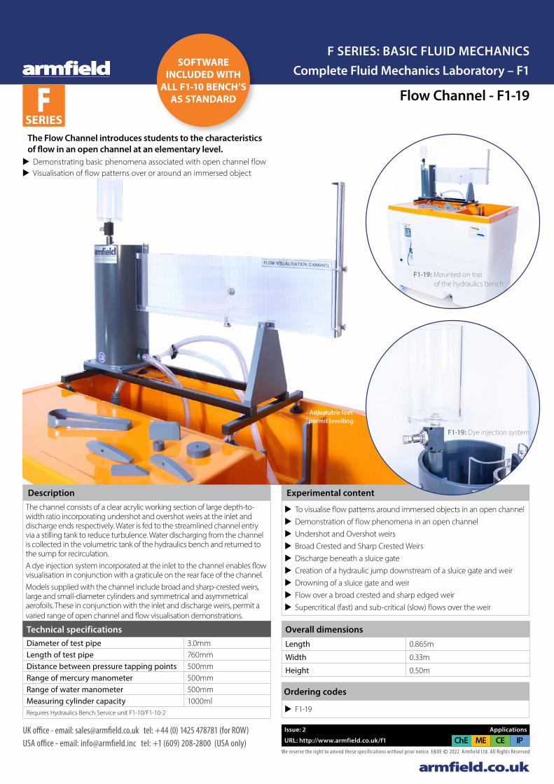
Flow Channel - F1-19
The Flow Channel introduces students to the characteristics of flow in an open channel at an elementary level. u Demonstrating basic phenomena associated with open channel flow u Visualisation of flow patterns over or around an immersed object
F1-19: Mounted on top of the hydraulics bench
Experimental content
u To visualise flow patterns around immersed objects in an open channel u Demonstration of flow phenomena in an open channel u Undershot and Overshot weirs u Broad Crested and Sharp Crested Weirs u Discharge beneath a sluice gate u Creation of a hydraulic jump downstream of a sluice gate and weir u Drowning of a sluice gate and weir u Flow over a broad crested and sharp edged weir u Supercritical (fast) and sub-critical (slow) flows over the weir
DescriptionThe channel consists of a clear acrylic working section of large depth-to-width ratio incorporating undershot and overshot weirs at the inlet and discharge ends respectively. Water is fed to the streamlined channel entry via a stilling tank to reduce turbulence. Water discharging from the channel is collected in the volumetric tank of the hydraulics bench and returned to the sump for recirculation.A dye injection system incorporated at the inlet to the channel enables flow visualisation in conjunction with a graticule on the rear face of the channel.Models supplied with the channel include broad and sharp-crested weirs, large and small-diameter cylinders and symmetrical and asymmetrical aerofoils. These in conjunction with the inlet and discharge weirs, permit a varied range of open channel and flow visualisation demonstrations.
Overall dimensionsLength 0.865m
Width 0.33m
Height 0.50m
Technical specificationsDiameter of test pipe 3.0mmLength of test pipe 760mmDistance between pressure tapping points 500mmRange of mercury manometer 500mmRange of water manometer 500mmMeasuring cylinder capacity 1000mlRequires Hydraulics Bench Service unit F1-10/F1-10-2
Ordering codes
u F1-19
F1-19: Dye injection system
- Adjustable feet permit levelling
F SERIES
Complete Fluid Mechanics Laboratory – F1F SERIES: BASIC FLUID MECHANICS
SOFTWARE INCLUDED WITH
ALL F1-10 BENCH’S AS STANDARD
armfield.co.ukWe reserve the right to amend these specif ications without prior notice. E&OE © 2022 Armfield Ltd. All Rights Reserved
UK office - email: [email protected] tel: +44 (0) 1425 478781 (for ROW)USA office - email: [email protected] tel: +1 (609) 208-2800 (USA only)
Issue: 2 Applications
URL: http://www.armfield.co.uk/f1 CE IPChE ME
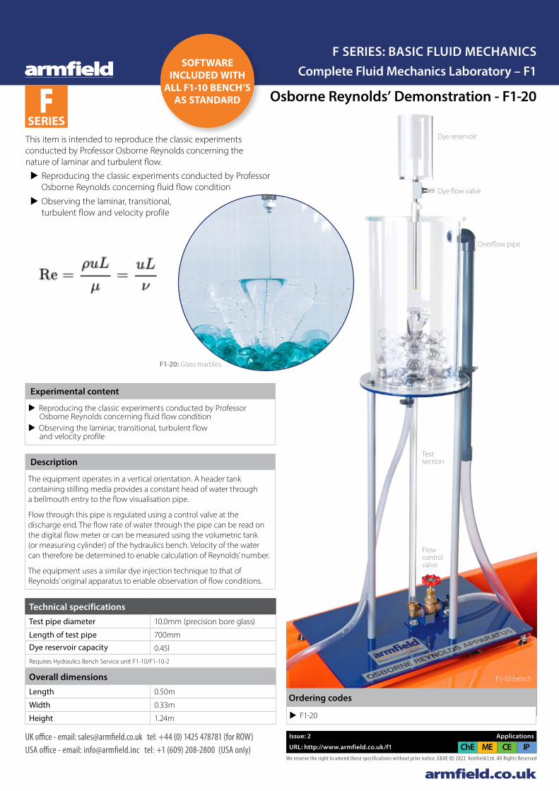
Osborne Reynolds’ Demonstration - F1-20
This item is intended to reproduce the classic experiments conducted by Professor Osborne Reynolds concerning the nature of laminar and turbulent flow.
u Reproducing the classic experiments conducted by Professor Osborne Reynolds concerning fluid flow condition
u Observing the laminar, transitional, turbulent flow and velocity profile
Experimental content
u Reproducing the classic experiments conducted by Professor Osborne Reynolds concerning fluid flow condition
u Observing the laminar, transitional, turbulent flow and velocity profile
Description
The equipment operates in a vertical orientation. A header tank containing stilling media provides a constant head of water through a bellmouth entry to the flow visualisation pipe.
Flow through this pipe is regulated using a control valve at the discharge end. The flow rate of water through the pipe can be read on the digital flow meter or can be measured using the volumetric tank (or measuring cylinder) of the hydraulics bench. Velocity of the water can therefore be determined to enable calculation of Reynolds’ number.
The equipment uses a similar dye injection technique to that of Reynolds’ original apparatus to enable observation of flow conditions.
Overall dimensionsLength 0.50m
Width 0.33m
Height 1.24m
Technical specificationsTest pipe diameter 10.0mm (precision bore glass)
Length of test pipe 700mmDye reservoir capacity 0.45l
Requires Hydraulics Bench Service unit F1-10/F1-10-2
u F1-20
Ordering codes
Dye reservoir
Dye flow valve
Overflow pipe
F1-10 bench
Test section
Flow control valve
F1-20: Glass marbles
F SERIES
Complete Fluid Mechanics Laboratory – F1F SERIES: BASIC FLUID MECHANICS
SOFTWARE INCLUDED WITH
ALL F1-10 BENCH’S AS STANDARD
armfield.co.ukWe reserve the right to amend these specif ications without prior notice. E&OE © 2022 Armfield Ltd. All Rights Reserved
UK office - email: [email protected] tel: +44 (0) 1425 478781 (for ROW)USA office - email: [email protected] tel: +1 (609) 208-2800 (USA only)
Issue: 2 Applications
URL: http://www.armfield.co.uk/f1 CE IPChE ME
Flow Meter Demonstration - F1-21F SERIES
Complete Fluid Mechanics Laboratory – F1F SERIES: BASIC FLUID MECHANICS
SOFTWARE INCLUDED WITH
ALL F1-10 BENCH’S AS STANDARD
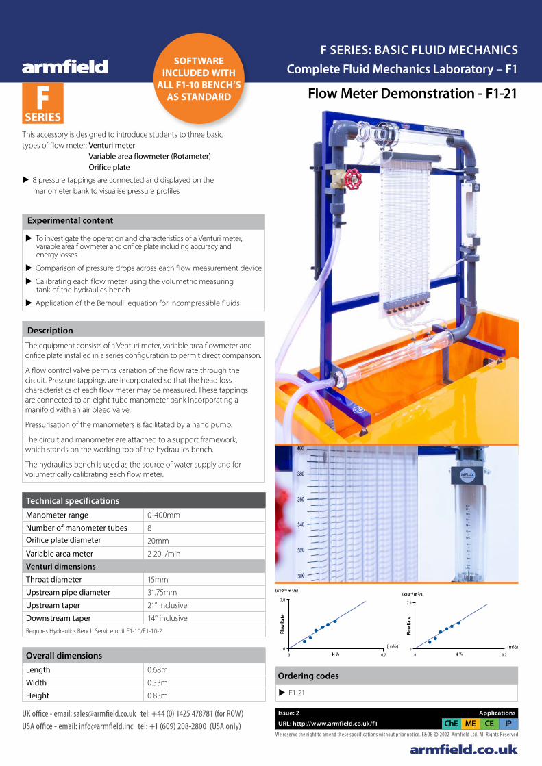
This accessory is designed to introduce students to three basic types of flow meter: Venturi meter
Variable area flowmeter (Rotameter) Orifice plate
u 8 pressure tappings are connected and displayed on the manometer bank to visualise pressure profiles
7.0
00 0.7
Flow
Rat
e
H /12
(x10 -4 m 3/s)
7.0
00 0.7
Flow
Rat
e
H /12
(x10 -4 m 3/s)
(m½)
(m½)
7.0
00 0.7
Flow
Rat
e
H /12
(x10 -4 m 3/s)
7.0
00 0.7
Flow
Rat
e
H /12
(x10 -4 m 3/s)
(m½)
(m½)
Experimental content
u To investigate the operation and characteristics of a Venturi meter, variable area flowmeter and orifice plate including accuracy and energy losses
u Comparison of pressure drops across each flow measurement device
u Calibrating each flow meter using the volumetric measuring tank of the hydraulics bench
u Application of the Bernoulli equation for incompressible fluids
Description
The equipment consists of a Venturi meter, variable area flowmeter and orifice plate installed in a series configuration to permit direct comparison.
A flow control valve permits variation of the flow rate through the circuit. Pressure tappings are incorporated so that the head loss characteristics of each flow meter may be measured. These tappings are connected to an eight-tube manometer bank incorporating a manifold with an air bleed valve.
Pressurisation of the manometers is facilitated by a hand pump.
The circuit and manometer are attached to a support framework, which stands on the working top of the hydraulics bench.
The hydraulics bench is used as the source of water supply and for volumetrically calibrating each flow meter.
Overall dimensionsLength 0.68m
Width 0.33m
Height 0.83m
Technical specificationsManometer range 0-400mm
Number of manometer tubes 8Orifice plate diameter 20mm
Variable area meter 2-20 l/min
Venturi dimensions
Throat diameter 15mm
Upstream pipe diameter 31.75mm
Upstream taper 21° inclusive
Downstream taper 14° inclusive
Requires Hydraulics Bench Service unit F1-10/F1-10-2
Ordering codes
u F1-21
Armfield F1-21 Datasheet v2b.indd 1Armfield F1-21 Datasheet v2b.indd 1 24/01/2022 12:27:4724/01/2022 12:27:47

armfield.co.ukWe reserve the right to amend these specif ications without prior notice. E&OE © 2022 Armfield Ltd. All Rights Reserved
UK office - email: [email protected] tel: +44 (0) 1425 478781 (for ROW)USA office - email: [email protected] tel: +1 (609) 208-2800 (USA only)
Issue: 2 Applications
URL: http://www.armfield.co.uk/f1 CE IPChE ME
Energy Losses in Bends and Fittings - F1-22F SERIES
Complete Fluid Mechanics Laboratory – F1F SERIES: BASIC FLUID MECHANICS
This accessory permits losses in different bends and fittings, sudden contraction, sudden enlargement and a typical control valve to be demonstrated.
u Mitre bend - 90° elbow - Short and long bends u Sudden contraction and sudden enlargement u Fully instrumented with upstream and downstream pressure tappings
u A bank of 12 water manometer tubes mounted on the framework for visualisation of the pressure drop profiles
u Differential Pressure Gauge for direction reading of losses through the gate valve
Experimental contentMeasuring the losses in the devices related to flow rate and calculating loss coefficients related to velocity head including:
u Short bend u Long bend u Elbow bend u Mitre bend u Area enlargement u Area contraction u Gate valve fitting u Comparing the pressure drop across each device
DescriptionThe equipment is mounted on a free-standing framework which supports the test pipework and instrumentation. The following typical pipe fittings are incorporated for study: mitre bend, 90° elbow, swept bends (large and small radius), sudden contraction and sudden enlargement. All are instrumented with upstream and downstream pressure tappings. These tappings are connected to a bank of 12 water manometer tubes mounted on the framework. Pressurisation of the manometers is facilitated by a hand pump. A gate valve is used to control the flow rate.A separate gate valve is instrumented with upstream and downstream pressure tappings which are connected to a differential gauge on the edge of the framework. The unit stands on the working top of the hydraulics bench which is also used as the source of water supply.
Overall dimensionsLength 0.63mWidth 0.33mHeight 0.83m
Technical specificationsPipe diameter 19.48mmDifferential pressure gauge 0-3 barEnlargement diameter 26.2mmContraction diameter 19.48mmFittings short bend
long bendelbow bend45° mitre bendenlargementcontractiongate valve
Manometer range 0-440mmNumber of manometer tubes 12Differential manometers 6Requires Hydraulics Bench Service unit F1-10/F1-10-2
u F1-22
Ordering codes
SOFTWARE INCLUDED WITH
ALL F1-10 BENCH’S AS STANDARD
Armfield F1-22 Datasheet v2b.indd 1Armfield F1-22 Datasheet v2b.indd 1 24/01/2022 12:36:5024/01/2022 12:36:50
armfield.co.ukWe reserve the right to amend these specif ications without prior notice. E&OE © 2022 Armfield Ltd. All Rights Reserved
UK office - email: [email protected] tel: +44 (0) 1425 478781 (for ROW)USA office - email: [email protected] tel: +1 (609) 208-2800 (USA only)
Issue: 2 Applications
URL: http://www.armfield.co.uk/f1 CE IPChE ME
Free and Forced Vortices - F1-23-MKIIF SERIES
Complete Fluid Mechanics Laboratory – F1F SERIES: BASIC FLUID MECHANICS
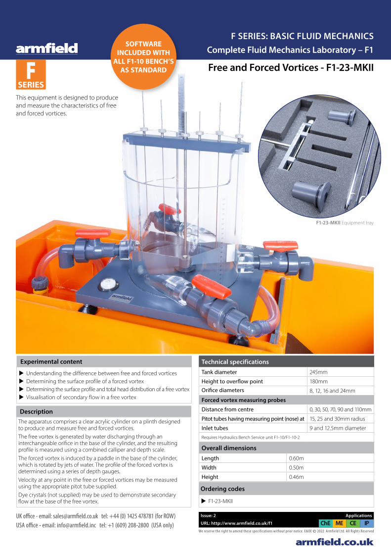
F1-23-MKII Equipment tray
This equipment is designed to produce and measure the characteristics of free and forced vortices.
Experimental content
u Understanding the difference between free and forced vortices u Determining the surface profile of a forced vortex u Determining the surface profile and total head distribution of a free vortex u Visualisation of secondary flow in a free vortex
DescriptionThe apparatus comprises a clear acrylic cylinder on a plinth designed to produce and measure free and forced vortices.The free vortex is generated by water discharging through an interchangeable orifice in the base of the cylinder, and the resulting profile is measured using a combined calliper and depth scale. The forced vortex is induced by a paddle in the base of the cylinder, which is rotated by jets of water. The profile of the forced vortex is determined using a series of depth gauges.Velocity at any point in the free or forced vortices may be measured using the appropriate pitot tube supplied. Dye crystals (not supplied) may be used to demonstrate secondary flow at the base of the free vortex.
Overall dimensionsLength 0.60m
Width 0.50m
Height 0.46m
Technical specificationsTank diameter 245mm
Height to overflow point 180mmOrifice diameters 8, 12, 16 and 24mm
Forced vortex measuring probes
Distance from centre 0, 30, 50, 70, 90 and 110mm
Pitot tubes having measuring point (nose) at 15, 25 and 30mm radius
Inlet tubes 9 and 12.5mm diameter
Requires Hydraulics Bench Service unit F1-10/F1-10-2
Ordering codes
u F1-23-MKII
SOFTWARE INCLUDED WITH
ALL F1-10 BENCH’S AS STANDARD
armfield.co.ukWe reserve the right to amend these specif ications without prior notice. E&OE © 2022 Armfield Ltd. All Rights Reserved
UK office - email: [email protected] tel: +44 (0) 1425 478781 (for ROW)USA office - email: [email protected] tel: +1 (609) 208-2800 (USA only)
Issue: 2 Applications
URL: http://www.armfield.co.uk/f1 CE IPChE ME
Hydraulic Ram - F1-24F SERIES
Complete Fluid Mechanics Laboratory – F1F SERIES: BASIC FLUID MECHANICS
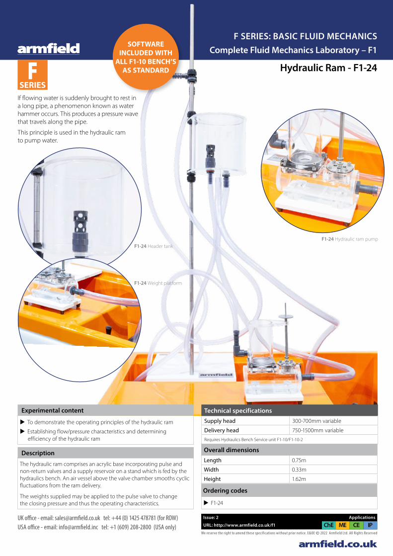
F1-24 Hydraulic ram pump
If flowing water is suddenly brought to rest in a long pipe, a phenomenon known as water hammer occurs. This produces a pressure wave that travels along the pipe.
This principle is used in the hydraulic ram to pump water.
Experimental content
u To demonstrate the operating principles of the hydraulic ram
u Establishing flow/pressure characteristics and determining efficiency of the hydraulic ram
Description
The hydraulic ram comprises an acrylic base incorporating pulse and non-return valves and a supply reservoir on a stand which is fed by the hydraulics bench. An air vessel above the valve chamber smooths cyclic fluctuations from the ram delivery.
The weights supplied may be applied to the pulse valve to change the closing pressure and thus the operating characteristics.
Overall dimensionsLength 0.75m
Width 0.33m
Height 1.62m
Technical specificationsSupply head 300-700mm variable
Delivery head 750-1500mm variable
Requires Hydraulics Bench Service unit F1-10/F1-10-2
u F1-24
Ordering codes
F1-24 Header tank
F1-24 Weight platform
SOFTWARE INCLUDED WITH
ALL F1-10 BENCH’S AS STANDARD
armfield.co.ukWe reserve the right to amend these specif ications without prior notice. E&OE © 2022 Armfield Ltd. All Rights Reserved
UK office - email: [email protected] tel: +44 (0) 1425 478781 (for ROW)USA office - email: [email protected] tel: +1 (609) 208-2800 (USA only)
Issue: 2 Applications
URL: http://www.armfield.co.uk/f1 CE IPChE ME
F SERIES
Complete Fluid Mechanics Laboratory – F1F SERIES: BASIC FLUID MECHANICS
Demonstration Pelton Turbine - F1-25
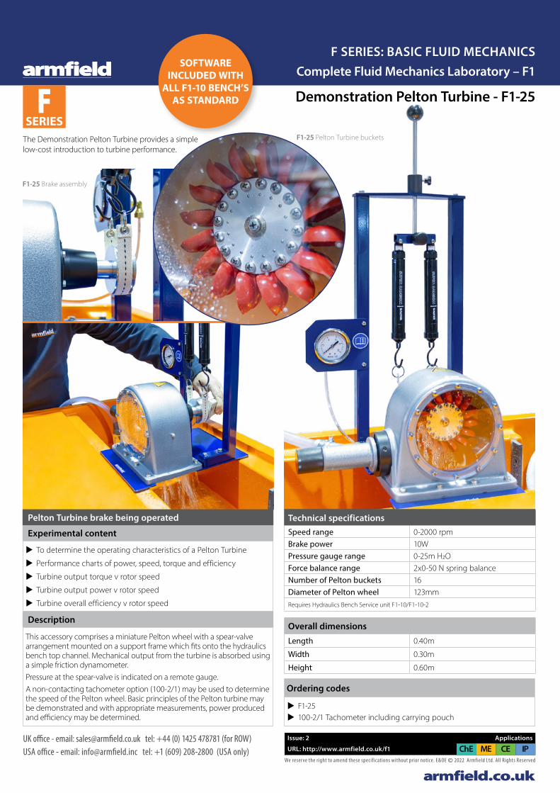
The Demonstration Pelton Turbine provides a simple low-cost introduction to turbine performance.
F1-25 Pelton Turbine buckets
F1-25 Brake assembly
Experimental content
u To determine the operating characteristics of a Pelton Turbine
u Performance charts of power, speed, torque and efficiency
u Turbine output torque v rotor speed
u Turbine output power v rotor speed
u Turbine overall efficiency v rotor speed
Description
This accessory comprises a miniature Pelton wheel with a spear-valve arrangement mounted on a support frame which fits onto the hydraulics bench top channel. Mechanical output from the turbine is absorbed using a simple friction dynamometer.Pressure at the spear-valve is indicated on a remote gauge. A non-contacting tachometer option (100-2/1) may be used to determine the speed of the Pelton wheel. Basic principles of the Pelton turbine may be demonstrated and with appropriate measurements, power produced and efficiency may be determined.
Pelton Turbine brake being operated
Overall dimensionsLength 0.40m
Width 0.30m
Height 0.60m
Technical specificationsSpeed range 0-2000 rpmBrake power 10WPressure gauge range 0-25m H2OForce balance range 2x0-50 N spring balanceNumber of Pelton buckets 16Diameter of Pelton wheel 123mmRequires Hydraulics Bench Service unit F1-10/F1-10-2
Ordering codes
u F1-25 u 100-2/1 Tachometer including carrying pouch
SOFTWARE INCLUDED WITH
ALL F1-10 BENCH’S AS STANDARD
armfield.co.ukWe reserve the right to amend these specif ications without prior notice. E&OE © 2022 Armfield Ltd. All Rights Reserved
UK office - email: [email protected] tel: +44 (0) 1425 478781 (for ROW)USA office - email: [email protected] tel: +1 (609) 208-2800 (USA only)
Issue: 2 Applications
URL: http://www.armfield.co.uk/f1 CE IPChE ME
F SERIES
Complete Fluid Mechanics Laboratory – F1F SERIES: BASIC FLUID MECHANICS
F1-27 Centrifugal Pump Characteristics
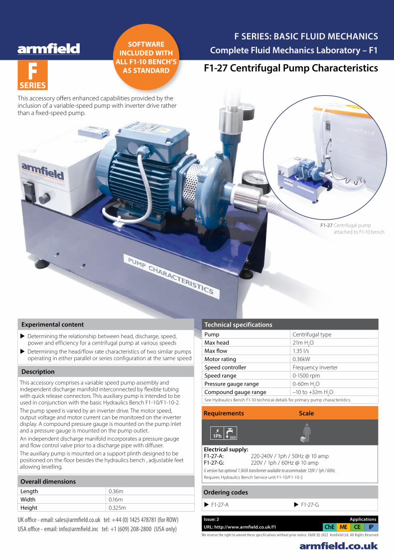
This accessory offers enhanced capabilities provided by the inclusion of a variable-speed pump with inverter drive rather than a fixed-speed pump.
F1-27 Centrifugal pump attached to F1-10 bench
Experimental content
u Determining the relationship between head, discharge, speed, power and efficiency for a centrifugal pump at various speeds
u Determining the head/flow rate characteristics of two similar pumps operating in either parallel or series configuration at the same speed
Description
This accessory comprises a variable speed pump assembly and independent discharge manifold interconnected by flexible tubing with quick release connectors. This auxiliary pump is intended to be used in conjunction with the basic Hydraulics Bench F1-10/F1-10-2. The pump speed is varied by an inverter drive. The motor speed, output voltage and motor current can be monitored on the inverter display. A compound pressure gauge is mounted on the pump inlet and a pressure gauge is mounted on the pump outlet.An independent discharge manifold incorporates a pressure gauge and flow control valve prior to a discharge pipe with diffuser.The auxiliary pump is mounted on a support plinth designed to be positioned on the floor besides the hydraulics bench , adjustable feet allowing levelling.
Electrical supply: F1-27-A: 220-240V / 1ph / 50Hz @ 10 amp F1-27-G: 220V / 1ph / 60Hz @ 10 ampG version has optional 1.5kVA transformer available to accommodate 120V / 1ph / 60Hz. Requires Hydraulics Bench Service unit F1-10/F1-10-2
Requirements Scale
COLD HOT
PC IFD 7
FM 6X
1Ph
COLD USB
oil DRAIN
COLD HOT
PC IFD 7
FM 6X
1Ph
COLD USB
oil HEARING PROTECTION
EXTRACTOR
PC IFD 7
FM 6X
1Ph
COLD USB
oil DRAIN
HEARING PROTECTION
EXTRACTOR GENERATOR
STEAMSTEAM
GENERATOR
STEAM
DRAIN
USB USB I/O
USB
3Ph
FM 6X
FM 6X
COLD
GRAVEL
DYE
COMP. AIR
GENERATOR
STEAM
FILTRATION CHILLER
PC
1Ph
IFD 7
F 1-10
HOT
DRAIN
SAND
OIL
EXTRACTOR
COMP. AIR
SOUND PROOFING
1Ph
COLD
Overall dimensionsLength 0.36mWidth 0.16mHeight 0.325m
Technical specificationsPump Centrifugal typeMax head 21m H2OMax flow 1.35 l/sMotor rating 0.36kWSpeed controller Frequency inverterSpeed range 0-1500 rpmPressure gauge range 0-60m H2OCompound gauge range –10 to +32m H2OSee Hydraulics Bench F1-10 technical details for primary pump characteristics.
Ordering codes
u F1-27-A u F1-27-G
SOFTWARE INCLUDED WITH
ALL F1-10 BENCH’S AS STANDARD
F SERIES
armfield.co.ukWe reserve the right to amend these specif ications without prior notice. E&OE © 2022 Armfield Ltd. All Rights Reserved
UK office - email: [email protected] tel: +44 (0) 1425 478781 (for ROW)USA office - email: [email protected] tel: +1 (609) 208-2800 (USA only)
Issue: 2 Applications
URL: http://www.armfield.co.uk/f1 CE IPChE ME
Complete Fluid Mechanics Laboratory – F1F SERIES: BASIC FLUID MECHANICS
Ordering codes
u F1-28
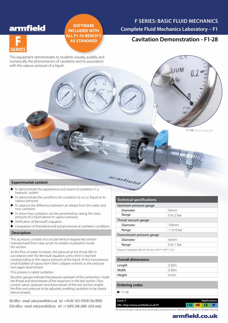
This equipment demonstrates to students visually, audibly and numerically the phenomenon of cavitation and its association with the vapour pressure of a liquid.
Overall dimensionsLength 0.30mWidth 0.30mHeight 0.15m
Technical specificationsUpstream pressure gauge Diameter 63mm Range 0 to 2 barThroat vacuum gauge Diameter 100mm Range -1 to 0 barDownstream pressure gauge Diameter 63mm Range 0 to 1 barRequires Hydraulics Bench Service unit F1-10/F1-10-2
F1-28 Vacuum gauge
Cavitation Demonstration - F1-28
SOFTWARE INCLUDED WITH
ALL F1-10 BENCH’S AS STANDARD
Description
This accessory consists of a circular Venturi-shaped test section manufactured from clear acrylic to enable visualisation inside the section. As the flow of water increases, the pressure at the throat falls in accordance with the Bernoulli equation until a limit is reached corresponding to the vapour pressure of the liquid. At this low pressure small bubbles of vapour form then collapse violently as the pressure rises again downstream.This process is called cavitation.Bourdon gauges indicate the pressure upstream of the contraction, inside the throat and downstream of the expansion in the test section. Flow control valves upstream and downstream of the test section enable the flow and pressure to be adjusted, enabling cavitation to be clearly demonstrated.
Experimental content
u To demonstrate the appearance and sound of cavitation in a hydraulic system
u To demonstrate the conditions for cavitation to occur (liquid at its vapour pressure)
u To observe the difference between air release from the water and true cavitation
u To show how cavitation can be prevented by raising the static pressure of a liquid above its vapour pressure
u Verification of Bernoulli’s equation u Comparison of theoretical and actual pressure at cavitation conditions

armfield.co.ukWe reserve the right to amend these specif ications without prior notice. E&OE © 2022 Armfield Ltd. All Rights Reserved
UK office - email: [email protected] tel: +44 (0) 1425 478781 (for ROW)USA office - email: [email protected] tel: +1 (609) 208-2800 (USA only)
Issue: 2 Applications
URL: http://www.armfield.co.uk/f1 CE IPChE ME
Fluid Statics and Manometry - F1-29
Experimental content
u Demonstrating the behaviour of liquids at rest (hydrostatics) u Showing that the free surface of a liquid is horizontal and
independent of cross section or inclination of the container u Effect of changes in air pressure above a liquid surface u Measuring the level of a liquid using basic measuring techniques such as
a scale, vernier depth gauge and inclined scale and the effect of parallax u Measuring small changes in liquid level using a micro-manometer u Measuring changes in liquid level using a Vernier hook and point gauge u Using a single limb manometer / piezometer tube to measure head u Using manometer tubes to measure differential pressure u Using an inclined manometer to measure small pressure differences u Using a ‘U’ tube manometer to measure pressure differences in
a gas (air over liquid) u Using an inverted pressurised ‘U’ tube manometer to measure
pressure differences in a liquid u Enlarged limb manometer u Using liquids with different densities to change the sensitivity
of a ‘U’ tube manometer u Demonstrating the effect of trapped air on the accuracy of a manometer u Demonstrating the effects caused by friction when a fluid is in motion
The right-hand manometer tube is separate from the other tubes and incorporates a pivot and indexing mechanism at the base that enables this tube to be inclined at fixed angles of 5°, 30°, 60° and 90° (vertical).The reservoir incorporates a hook and point gauge with Vernier scale mounted through the lid that enables large changes in level to be measured with precision. A vertical transparent piezometer tube through the lid of the reservoir enables the static head above the water in the reservoir to be observed when the air space above the water is not open to the atmosphere.
F1-29 Manometer
F1-29: Different inclination angles in the inclined manometer
Overall dimensions
Length 0.425m
Width 0.15m
Height 1.09m
Technical specifications
Max depth inside reservoir 574mm
Inside diameter of reservoir 100mm
Scale length of manometer tubes 460mm
Ordering codes
u F1-29
F SERIES
Complete Fluid Mechanics Laboratory – F1F SERIES: BASIC FLUID MECHANICS
armfield.co.ukWe reserve the right to amend these specif ications without prior notice. E&OE © 2022 Armfield Ltd. All Rights Reserved
UK office - email: [email protected] tel: +44 (0) 1425 478781 (for ROW)USA office - email: [email protected] tel: +1 (609) 208-2800 (USA only)
Issue: 2 Applications
URL: http://www.armfield.co.uk/f1 CE IPChE ME
F1-30 Fluid Properties ApparatusF SERIES
Complete Fluid Mechanics Laboratory – F1F SERIES: BASIC FLUID MECHANICS
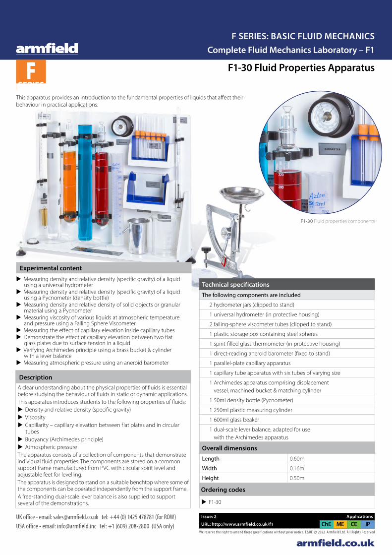
F1-30 Fluid properties components
DescriptionA clear understanding about the physical properties of fluids is essential before studying the behaviour of fluids in static or dynamic applications.This apparatus introduces students to the following properties of fluids:
u Density and relative density (specific gravity) u Viscosity u Capillarity – capillary elevation between flat plates and in circular
tubes u Buoyancy (Archimedes principle) u Atmospheric pressure
The apparatus consists of a collection of components that demonstrate individual fluid properties. The components are stored on a common support frame manufactured from PVC with circular spirit level and adjustable feet for levelling. The apparatus is designed to stand on a suitable benchtop where some of the components can be operated independently from the support frame.A free-standing dual-scale lever balance is also supplied to support several of the demonstrations.
This apparatus provides an introduction to the fundamental properties of liquids that affect their behaviour in practical applications.
Overall dimensions
Length 0.60m
Width 0.16m
Height 0.50m
Ordering codes
u F1-30
Technical specifications
The following components are included
2 hydrometer jars (clipped to stand)
1 universal hydrometer (in protective housing)
2 falling-sphere viscometer tubes (clipped to stand)
1 plastic storage box containing steel spheres
1 spirit-filled glass thermometer (in protective housing)
1 direct-reading aneroid barometer (fixed to stand)
1 parallel-plate capillary apparatus
1 capillary tube apparatus with six tubes of varying size
1 Archimedes apparatus comprising displacement vessel, machined bucket & matching cylinder
1 50ml density bottle (Pycnometer)
1 250ml plastic measuring cylinder
1 600ml glass beaker
1 dual-scale lever balance, adapted for use with the Archimedes apparatus
Experimental content
u Measuring density and relative density (specific gravity) of a liquid using a universal hydrometer
u Measuring density and relative density (specific gravity) of a liquid using a Pycnometer (density bottle)
u Measuring density and relative density of solid objects or granular material using a Pycnometer
u Measuring viscosity of various liquids at atmospheric temperature and pressure using a Falling Sphere Viscometer
u Measuring the effect of capillary elevation inside capillary tubes u Demonstrate the effect of capillary elevation between two flat
glass plates due to surface tension in a liquid u Verifying Archimedes principle using a brass bucket & cylinder
with a lever balance u Measuring atmospheric pressure using an aneroid barometer
Armfield F1-30 Datasheet v2b.indd 1Armfield F1-30 Datasheet v2b.indd 1 24/01/2022 13:13:4524/01/2022 13:13:45
armfield.co.ukWe reserve the right to amend these specif ications without prior notice. E&OE © 2022 Armfield Ltd. All Rights Reserved
UK office - email: [email protected] tel: +44 (0) 1425 478781 (for ROW)USA office - email: [email protected] tel: +1 (609) 208-2800 (USA only)
Issue: 2 Applications
URL: http://www.armfield.co.uk/f1 CE IPChE ME
F1-31 PASCAL’S APPARATUSF SERIES
Complete Fluid Mechanics Laboratory – F1F SERIES: BASIC FLUID MECHANICS
Technical specifications
Parallel vessel 26mm inside diameter
Conical vessel 26-101mm inside diameter at top
Tapered vessel 26mm to 9mm inside diameter at top
Diameter at diaphragm 56mm
Maximum depth of water 228mm (to top of vessels)
Overall dimensions
Length 0.35m
Width 0.135m
Height 0.45m
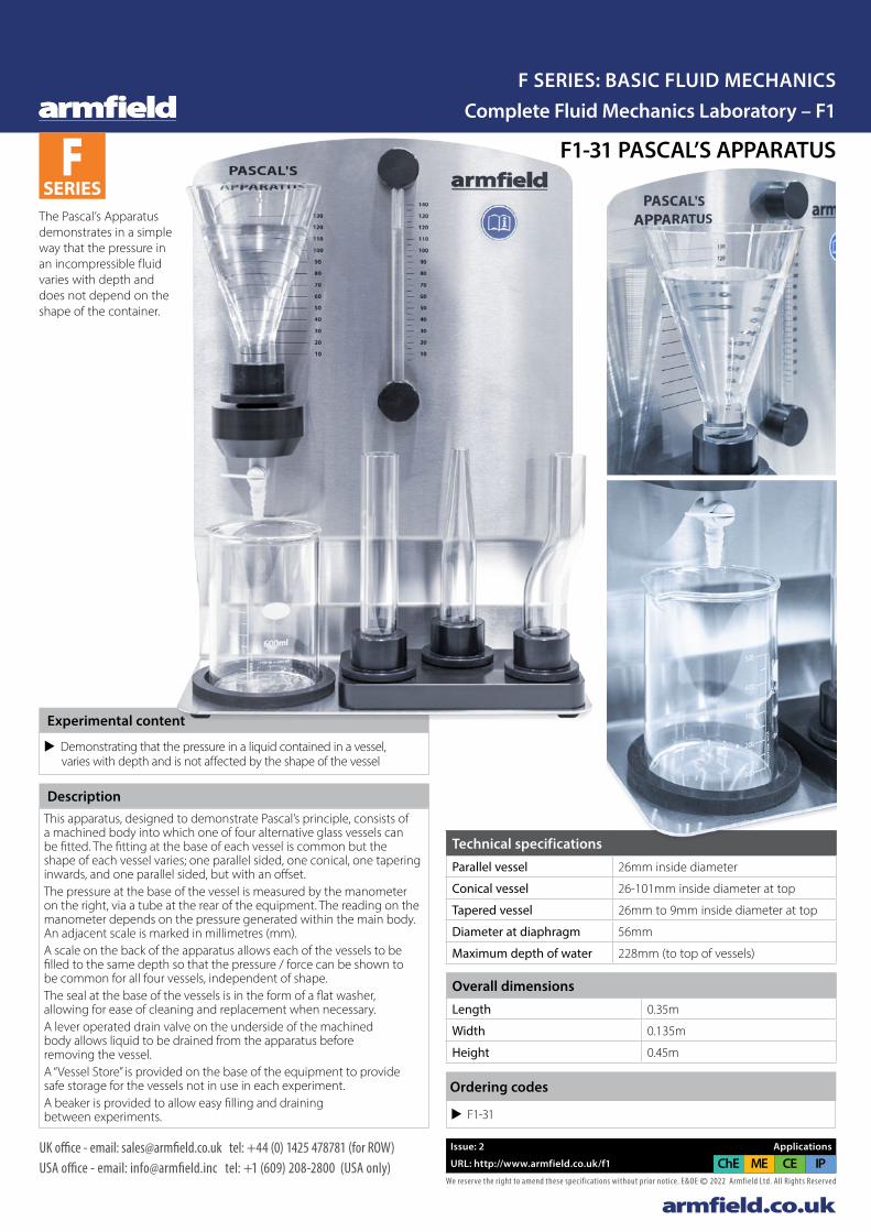
Experimental content
u Demonstrating that the pressure in a liquid contained in a vessel, varies with depth and is not affected by the shape of the vessel
DescriptionThis apparatus, designed to demonstrate Pascal’s principle, consists of a machined body into which one of four alternative glass vessels can be fitted. The fitting at the base of each vessel is common but the shape of each vessel varies; one parallel sided, one conical, one tapering inwards, and one parallel sided, but with an offset.The pressure at the base of the vessel is measured by the manometer on the right, via a tube at the rear of the equipment. The reading on the manometer depends on the pressure generated within the main body. An adjacent scale is marked in millimetres (mm).A scale on the back of the apparatus allows each of the vessels to be filled to the same depth so that the pressure / force can be shown to be common for all four vessels, independent of shape.The seal at the base of the vessels is in the form of a flat washer, allowing for ease of cleaning and replacement when necessary.A lever operated drain valve on the underside of the machined body allows liquid to be drained from the apparatus before removing the vessel.A “Vessel Store” is provided on the base of the equipment to provide safe storage for the vessels not in use in each experiment.A beaker is provided to allow easy filling and draining between experiments. u F1-31
Ordering codes
The Pascal’s Apparatus demonstrates in a simple way that the pressure in an incompressible fluid varies with depth and does not depend on the shape of the container.
Armfield F1-31 Datasheet v2b.indd 1Armfield F1-31 Datasheet v2b.indd 1 24/01/2022 14:27:0124/01/2022 14:27:01
armfield.co.ukWe reserve the right to amend these specif ications without prior notice. E&OE © 2022 Armfield Ltd. All Rights Reserved
UK office - email: [email protected] tel: +44 (0) 1425 478781 (for ROW)USA office - email: [email protected] tel: +1 (609) 208-2800 (USA only)
Issue: 2 Applications
URL: http://www.armfield.co.uk/f1 CE IPChE ME
F1-32 FRANCIS TURBINE
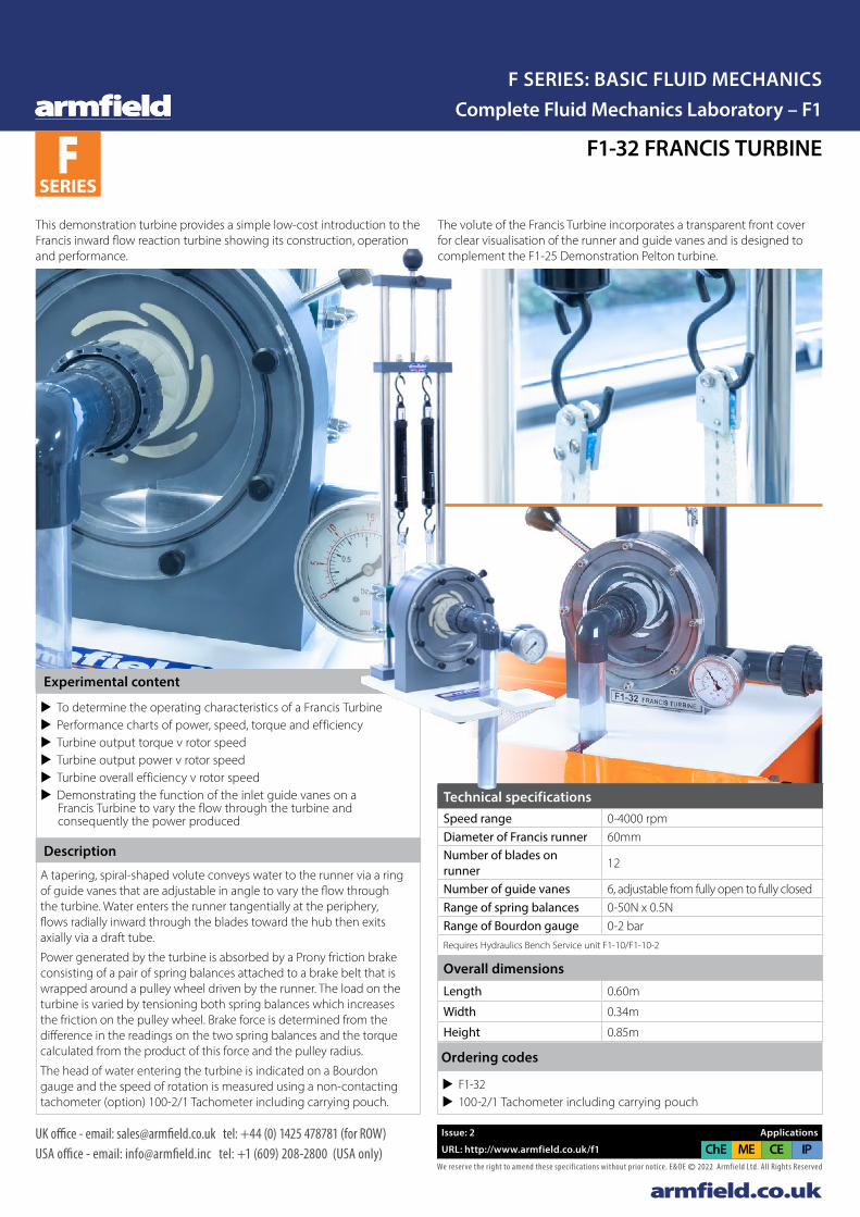
This demonstration turbine provides a simple low-cost introduction to the Francis inward flow reaction turbine showing its construction, operation and performance.
The volute of the Francis Turbine incorporates a transparent front cover for clear visualisation of the runner and guide vanes and is designed to complement the F1-25 Demonstration Pelton turbine.
Experimental content
u To determine the operating characteristics of a Francis Turbine u Performance charts of power, speed, torque and efficiency u Turbine output torque v rotor speed u Turbine output power v rotor speed u Turbine overall efficiency v rotor speed u Demonstrating the function of the inlet guide vanes on a
Francis Turbine to vary the flow through the turbine and consequently the power produced
Description
A tapering, spiral-shaped volute conveys water to the runner via a ring of guide vanes that are adjustable in angle to vary the flow through the turbine. Water enters the runner tangentially at the periphery, flows radially inward through the blades toward the hub then exits axially via a draft tube.
Power generated by the turbine is absorbed by a Prony friction brake consisting of a pair of spring balances attached to a brake belt that is wrapped around a pulley wheel driven by the runner. The load on the turbine is varied by tensioning both spring balances which increases the friction on the pulley wheel. Brake force is determined from the difference in the readings on the two spring balances and the torque calculated from the product of this force and the pulley radius.
The head of water entering the turbine is indicated on a Bourdon gauge and the speed of rotation is measured using a non-contacting tachometer (option) 100-2/1 Tachometer including carrying pouch.
Technical specificationsSpeed range 0-4000 rpmDiameter of Francis runner 60mmNumber of blades on runner 12
Number of guide vanes 6, adjustable from fully open to fully closedRange of spring balances 0-50N x 0.5NRange of Bourdon gauge 0-2 barRequires Hydraulics Bench Service unit F1-10/F1-10-2
Overall dimensionsLength 0.60m
Width 0.34m
Height 0.85m
u F1-32 u 100-2/1 Tachometer including carrying pouch
Ordering codes
F SERIES
Complete Fluid Mechanics Laboratory – F1F SERIES: BASIC FLUID MECHANICS
armfield.co.ukWe reserve the right to amend these specif ications without prior notice. E&OE © 2022 Armfield Ltd. All Rights Reserved
UK office - email: [email protected] tel: +44 (0) 1425 478781 (for ROW)USA office - email: [email protected] tel: +1 (609) 208-2800 (USA only)
Issue: 2 Applications
URL: http://www.armfield.co.uk/f1 CE IPChE ME
F1-32 FRANCIS TURBINE
This demonstration turbine provides a simple low-cost introduction to the Francis inward flow reaction turbine showing its construction, operation and performance.
The volute of the Francis Turbine incorporates a transparent front cover for clear visualisation of the runner and guide vanes and is designed to complement the F1-25 Demonstration Pelton turbine.
Experimental content
u To determine the operating characteristics of a Francis Turbine u Performance charts of power, speed, torque and efficiency u Turbine output torque v rotor speed u Turbine output power v rotor speed u Turbine overall efficiency v rotor speed u Demonstrating the function of the inlet guide vanes on a
Francis Turbine to vary the flow through the turbine and consequently the power produced
Description
A tapering, spiral-shaped volute conveys water to the runner via a ring of guide vanes that are adjustable in angle to vary the flow through the turbine. Water enters the runner tangentially at the periphery, flows radially inward through the blades toward the hub then exits axially via a draft tube.
Power generated by the turbine is absorbed by a Prony friction brake consisting of a pair of spring balances attached to a brake belt that is wrapped around a pulley wheel driven by the runner. The load on the turbine is varied by tensioning both spring balances which increases the friction on the pulley wheel. Brake force is determined from the difference in the readings on the two spring balances and the torque calculated from the product of this force and the pulley radius.
The head of water entering the turbine is indicated on a Bourdon gauge and the speed of rotation is measured using a non-contacting tachometer (option) 100-2/1 Tachometer including carrying pouch.
Technical specificationsSpeed range 0-4000 rpmDiameter of Francis runner 60mmNumber of blades on runner 12
Number of guide vanes 6, adjustable from fully open to fully closedRange of spring balances 0-50N x 0.5NRange of Bourdon gauge 0-2 barRequires Hydraulics Bench Service unit F1-10/F1-10-2
Overall dimensionsLength 0.60m
Width 0.34m
Height 0.85m
u F1-32 u 100-2/1 Tachometer including carrying pouch
Ordering codes
F SERIES
Complete Fluid Mechanics Laboratory – F1F SERIES: BASIC FLUID MECHANICS

Pitot Tube Demonstrator – F1-33
The pitot tube can be moved across the cross-section of the pipe in order to measure the dynamic head profile.
F1-33 Pitot tube mounting base
Technical specificationsInside diameter of test pipe 27mmPitot-static tube outside diameter 6mmPitot-static tube inside diameter 3.2mmScale length of manometer tubes 500mmCross section of manometer tubes 5.6mm diameterRange of pitot-static tube traverse 21mm with 3mm scale incrementsRequires Hydraulics Bench Service unit F1-10/F1-10-2
Overall dimensionsLength 1.00mWidth 0.35mHeight 0.52m
Ordering codes u F1-33
F SERIES
armfield.co.ukWe reserve the right to amend these specif ications without prior notice. E&OE © 2022 Armfield Ltd. All Rights Reserved
UK office - email: [email protected] tel: +44 (0) 1425 478781 (for ROW)USA office - email: [email protected] tel: +1 (609) 208-2800 (USA only)
Issue: 2 Applications
URL: http://www.armfield.co.uk/f1 CE IPChE ME
Complete Fluid Mechanics Laboratory – F1F SERIES: BASIC FLUID MECHANICS
Experimental content
u Demonstrating the use of a pitot-static tube to measure the dynamic head produced by water flowing inside a pipe using a pressurised water manometer to measure the difference between the static head and the total head
u Demonstrating the relationship between static head, total head and dynamic head
u Demonstrating how a pitot-static tube can be used to determine the velocity of a fluid
u Demonstrating how the dynamic head of a fluid flowing inside a pipe varies with radius due to the development of a boundary layer at the wall of the pipe
u Demonstrating how the dynamic head profile varies at the entrance to a pipe downstream of a 90 degree bend with undeveloped flow
The pitot tube can be moved across the cross-section of the pipe in order to measure the dynamic head profile.
The position of the measuring tip relative to the wall of the pipe can be read on a scale.
The pitot tube is connected to a pressurised water manometer to measure the differential head across the pitot static tube.
Description
Armfield F1-33 DataSheet v2b.indd 1Armfield F1-33 DataSheet v2b.indd 1 24/01/2022 14:03:0224/01/2022 14:03:02
armfield.co.ukWe reserve the right to amend these specif ications without prior notice. E&OE © 2022 Armfield Ltd. All Rights Reserved
UK office - email: [email protected] tel: +44 (0) 1425 478781 (for ROW)USA office - email: [email protected] tel: +1 (609) 208-2800 (USA only)
Issue: 1 Applications
URL: http://www.armfield.co.uk/f1 CE IPChE ME
Series & Parallel Pumps - F1-35F SERIES
Complete Fluid Mechanics Laboratory – F1F SERIES: BASIC FLUID MECHANICS
Overall dimensionsLength 0.85mWidth 0.35mHeight 0.55mPacked and crated shipping specificationsVolume 1.2m3
Gross weight 20Kg
Technical detailsPower Consumption 48W (max. per pump, for this application)
Max. Flow Rate 22L/min (max per pump (series), for this application (44L/min in parallel)
Max. Head 0.96m (datum to manifold gauge) (max pump head = 11m)
Constant head tank 2L (approx)Speed range 0-22 L/min Measuring rangesPressure (inlet) 1 x 2.0 barPressure (outlet) 2 x 2.2 barSee Hydraulics Bench F1-10 technical details for primary pump characteristics.
Specifically requires Hydraulics Bench Service unit F1-10-2 for operation
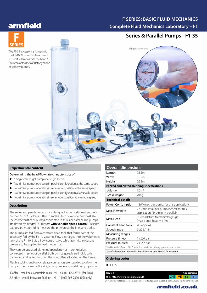
Experimental content
Determining the head/flow rate characteristics of: u A single centrifugal pump at a single speed u Two similar pumps operating in parallel configuration at the same speed u Two similar pumps operating in series configuration at the same speed u Two similar pumps operating in parallel configuration at a variable speed u Two similar pumps operating in series configuration at a variable speed
The series and parallel accessory is designed to be positioned securely on the F1-10-2 Hydraulics Bench and has two pumps to demonstrate the characteristics of pumps connected in series or parallel. The pumps are driven by integral DC motors with variable speed control. Pressure gauges are mounted to measure the pressure at the inlet and outlet.
The pumps are fed from a constant head tank that forms part of the accessory, fed by the F1-10-2 pump. Flow discharges into the volumetric tank of the F1-10-2 via a flow control valve which permits an output pressure to be applied to load the pumps.
They can be operated either independently or in conjunction, connected in series or parallel. Both pumps speeds are individually controlled and varied by using the controllers allocated on the frame.
Flexible tubing and quick release connectors are supplied to allow the pumps to be connected for single pump, series or parallel pump operation.
Description
Ordering codes
u F1-35
The F1-35 accessory is for use with the F1-10-2 Hydraulics Bench and is used to demonstrate the head / flow characteristics of Rotodynamic or Velocity pumps.
F1-35 Flow valve

armfield.co.uk
FE SERIES
Hele Shaw Apparatus – F1-38
The Armfield F1-38 Hele Shaw Apparatus enables investigation into the principles of potential flow and enables modelling of appropriate physical systems.
It allows students to study various source and sink arrangements and look at flow around a variety of different shaped models.
Issue: 1 Applications
URL: http://www.armfield.co.uk/f1-38 ChE IP
F1-38 - Hele Shaw Apparatus
F1-38- Flow through a sudden contraction
Sinks and sources may be used in combination with the flow of water between the plates to simulate a variety of flow situations.
Complete Fluid Mechanics Laboratory – F1F SERIES: BASIC FLUID MECHANICS
We reserve the right to amend these specif ications without prior notice. E&OE © 2022 Armfield Ltd. All Rights Reserved
UK office - email: [email protected] tel: +44 (0) 1425 478781 (for ROW)USA office - email: [email protected] tel: +1 (609) 208-2800 (USA only)
EXPERIMENT TO DEMONSTRATE POTENTIAL FLOW IN FLUID DYNAMICSSUPPLIED WITH SPARE MATERIAL FOR USER DEFINED SHAPES SUPPLIED WITH COMPREHENSIVE MANUAL
u Highly visual apparatus enabling the demonstration of a wide variety of flow patterns around different shapes
u Includes dye injection system
u Accessory to F1-10 bench
u Supplied with spare material for user defined shapes
u Optional visualiser F1-36b allows the user to capture or project video or still images via use of the supplied USB camera
u Supplied with comprehensive manual
Features
Valve operation and shut-off taps Flow straightener and dye injection system Bubble level Capture video or still images
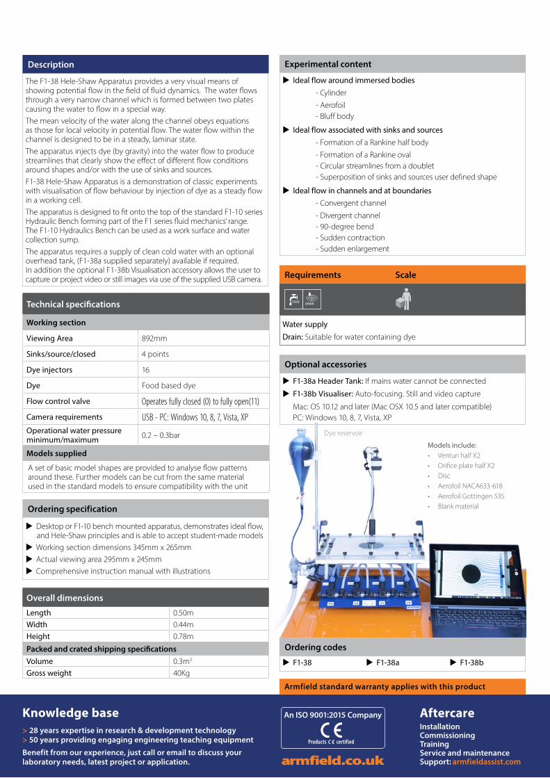
Products certified
An ISO 9001:2015 Company
armfield.co.uk
Knowledge base> 28 years expertise in research & development technology > 50 years providing engaging engineering teaching equipment
Benefit from our experience, just call or email to discuss your laboratory needs, latest project or application.
AftercareInstallation Commissioning TrainingService and maintenance Support: armfieldassist.com
Armfield standard warranty applies with this product
Technical specifications
Working section
Viewing Area 892mm
Sinks/source/closed 4 points
Dye injectors 16
Dye Food based dye
Flow control valve Operates fully closed (0) to fully open(11)
Camera requirements USB - PC: Windows 10, 8, 7, Vista, XPOperational water pressure minimum/maximum 0.2 – 0.3bar
Models supplied
A set of basic model shapes are provided to analyse flow patterns around these. Further models can be cut from the same material used in the standard models to ensure compatibility with the unit
u Ideal flow around immersed bodies - Cylinder
- Aerofoil - Bluff body
u Ideal flow associated with sinks and sources - Formation of a Rankine half body
- Formation of a Rankine oval - Circular streamlines from a doublet - Superposition of sinks and sources user defined shape
u Ideal flow in channels and at boundaries - Convergent channel
- Divergent channel - 90-degree bend - Sudden contraction - Sudden enlargement
Experimental content
Models include:• Venturi half X2• Orifice plate half X2• Disc• Aerofoil NACA633-618• Aerofoil Gottingen 535• Blank material
Dye reservoir
u F1-38a Header Tank: If mains water cannot be connected
u F1-38b Visualiser: Auto-focusing. Still and video capture
Mac: OS 10.12 and later (Mac OSX 10.5 and later compatible)PC: Windows 10, 8, 7, Vista, XP
Optional accessories
The F1-38 Hele-Shaw Apparatus provides a very visual means of showing potential flow in the field of fluid dynamics. The water flows through a very narrow channel which is formed between two plates causing the water to flow in a special way. The mean velocity of the water along the channel obeys equations as those for local velocity in potential flow. The water flow within the channel is designed to be in a steady, laminar state. The apparatus injects dye (by gravity) into the water flow to produce streamlines that clearly show the effect of different flow conditions around shapes and/or with the use of sinks and sources. F1-38 Hele-Shaw Apparatus is a demonstration of classic experiments with visualisation of flow behaviour by injection of dye as a steady flow in a working cell. The apparatus is designed to fit onto the top of the standard F1-10 series Hydraulic Bench forming part of the F1 series fluid mechanics’ range. The F1-10 Hydraulics Bench can be used as a work surface and water collection sump. The apparatus requires a supply of clean cold water with an optional overhead tank, (F1-38a supplied separately) available if required. In addition the optional F1-38b Visualisation accessory allows the user to capture or project video or still images via use of the supplied USB camera.
Description
u F1-38 u F1-38a u F1-38b
Ordering codes
u Desktop or F1-10 bench mounted apparatus, demonstrates ideal flow, and Hele-Shaw principles and is able to accept student-made models
u Working section dimensions 345mm x 265mm u Actual viewing area 295mm x 245mm u Comprehensive instruction manual with illustrations
Ordering specification
Overall dimensions
Length 0.50mWidth 0.44mHeight 0.78m
Packed and crated shipping specificationsVolume 0.3m3
Gross weight 40Kg
Water supply
Drain: Suitable for water containing dye
Requirements Scale
COLD HOT
PC IFD 7
FM 6X
1Ph
COLD USB
oil DRAIN
HEARING PROTECTION
EXTRACTOR
COLD HOT
PC IFD 7
FM 6X
1Ph
COLD USB
oil DRAIN
HEARING PROTECTION
EXTRACTOR
COLD HOT
PC IFD 7
FM 6X
1Ph
COLD USB
oil HEARING PROTECTION
EXTRACTOR
PC IFD 7
FM 6X
1Ph
COLD USB
oil DRAIN
HEARING PROTECTION
EXTRACTOR GENERATOR
STEAMSTEAM
GENERATOR
STEAMDRAIN
USB USB I/O
USB
3Ph
FM 6X
FM 6X
COLD
GRAVEL
DYE
COMP. AIR
GENERATOR
STEAM
FILTRATION CHILLER
PC
1Ph
IFD 7
F 1-10
HOT
DRAIN
SAND
OIL
EXTRACTOR
COMP. AIR
SOUND PROOFINGCOLD HOT
PC IFD 7
FM 6X
1Ph
COLD USB
oil HEARING PROTECTION
EXTRACTOR
PC IFD 7
FM 6X
1Ph
COLD USB
oil DRAIN
HEARING PROTECTION
EXTRACTOR GENERATOR
STEAMSTEAM
GENERATOR
STEAMDRAIN
USB USB I/O
USB
3Ph
FM 6X
FM 6X
COLD
GRAVEL
DYE
COMP. AIR
GENERATOR
STEAM
FILTRATION CHILLER
PC
1Ph
IFD 7
F 1-10
HOT
DRAIN
SAND
OIL
EXTRACTOR
COMP. AIR
SOUND PROOFING

Complete Fluid Mechanics Laboratory – F1F SERIES: BASIC FLUID MECHANICS
Part of Judges Scientific PLC
armfield®
REPRESENTATIVES IN MORE THAN 80 COUNTRIES
Products certified
An ISO 9001:2015 Company
armfield worldwide
U.S. Office:
Armfield Inc.9 Trenton Lakewood RoadClarksburg NJ 08510USA
Tel/Fax: +1 (609) 208-2800E-mail: [email protected]: armfieldassist.com
Head Office:
Armfield Limited10 Headlands Business Park,Ringwood, HampshireBH24 3PB England
Telephone: +44 (0)1425 478781 E-mail: [email protected]: armfieldassist.com
Innovative engineering teaching and research equipment 2021© Armfield Ltd. All Rights Reserved. We reserve the right to amend these specifications without prior notice. E&OE
To locate a contact in your area visit:
www.armfield.co.uk/contact-armfield/
Our Commitment to you
Armfield recognises that it is not enough to just supply quality engineering equipment, but that it must also ensure a complete range of services both pre and post-sale:
u Supplied equipment meets global curriculum requirements
u Expert consultation in laboratory design and layout
u Professional installation and commissioning service
u Comprehensive training for all products in house or on site
u Detailed learning outcomes and experiments supplied with all equipment
u In house trials (industrial and research)
u Two year warranty on all products
u Dedicated aftersales service