Flow resistance in smooth rectangular open-channels with low aspect ratios
19
1 Flow resistance in smooth rectangular open-channels with low aspect ratios Nguyen Ba Tuyen 1 and Nian-Sheng Cheng 2 1 Research Student, School of Civil and Environmental Engineering, Nanyang Technological University, Nanyang Avenue, Singapore 639798. Email: [email protected] 2 Associate Professor, School of Civil and Environmental Engineering, Nanyang Technological University, Nanyang Avenue, Singapore 639798. Email: [email protected] Abstract This note shows an approach that is useful for evaluating the resistance to flows in narrow open channels. A series of experiments were first carried out in a smooth rectangular open channel of which the aspect ratio varied from 0.12 to 1.53. Experimental data collected were then used to validate a resistance formula that was proposed previously by modifying Prandtl’s friction law. Introduction For many practical applications, open channel friction could be estimated by treating the channel as an equivalent pipe with a diameter four times the mean hydraulic radius. However, open channel flows are generally considered more complicated than circular pipe flows, due to the existence of secondary currents, a free surface, and the non-uniform distribution of
Transcript of Flow resistance in smooth rectangular open-channels with low aspect ratios

1
Flow resistance in smooth rectangular open-channels with low aspect ratios
Nguyen Ba Tuyen1 and Nian-Sheng Cheng2
1 Research Student, School of Civil and Environmental Engineering, Nanyang Technological
University, Nanyang Avenue, Singapore 639798. Email: [email protected]
2 Associate Professor, School of Civil and Environmental Engineering, Nanyang Technological
University, Nanyang Avenue, Singapore 639798. Email: [email protected]
Abstract
This note shows an approach that is useful for evaluating the resistance to flows in narrow open
channels. A series of experiments were first carried out in a smooth rectangular open channel of
which the aspect ratio varied from 0.12 to 1.53. Experimental data collected were then used to
validate a resistance formula that was proposed previously by modifying Prandtl’s friction law.
Introduction
For many practical applications, open channel friction could be estimated by treating the
channel as an equivalent pipe with a diameter four times the mean hydraulic radius. However,
open channel flows are generally considered more complicated than circular pipe flows, due to
the existence of secondary currents, a free surface, and the non-uniform distribution of
2
boundary shear stress. Therefore, the treatment of open channel resistance simply by analogy
with pipe friction is often found inappropriate (e.g. Montes 1998, Cheng et al. 2011).
Recently, by modifying Prandtl’s friction law, Cheng et al. (2011) developed an approach
for evaluating the friction of smooth rectangular channels. They expressed the open channel
friction factor, fch, as a function of the Reynolds number and the aspect ratio as follows:
−−⎡ ⎤⎛ ⎞+
= ⎢ ⎥⎜ ⎟⎢ ⎥⎝ ⎠⎣ ⎦
21210.33 log 0.11Re w
ch chwf e
w
(1)
where ( )ν=Re 4ch hR V is the channel Reynolds number, V is the average velocity, Rh is the
hydraulic radius, ν is the kinematic viscosity of the fluid, α= / 2w for α ≥ 2 and α2 / for α < 2,
α (= B/h) is the aspect ratio, B is the channel width, and h is the flow depth. Cheng et al. (2011)
showed that Eq. (1) performs much better than several other formulas available in the literature,
which usually were derived by reconciling the resistance difference between circular pipes and
rectangular channels. They verified Eq. (1) with their own experimental data and also those
presented by Tracy and Lester (1961) and Knight et al. (1984), of which α varies from 1.07 to 15
and Rech from 7.7×10³ to 5.5×10⁵. It should be mentioned that the data employed for the
verification only included a few measurements for low aspect ratios, say, α ≤ 2. In addition, it
also is noted that the information for experiments conducted for low aspect ratios is also very
limited in the literature. Therefore, to further verify the applicability of Eq. (1) for low aspect
ratios, additional data were collected from narrow open channel experiments that were
purposely designed in this study. The study results may also be useful for engineering
applications such as two-dimensional approximation studies of open channel flows and
validation of numerical models.
3
Experiments
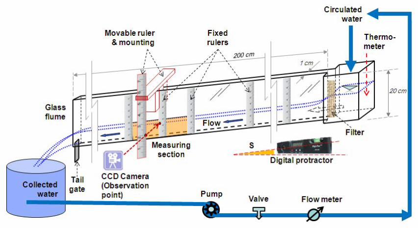
Experiments were conducted in a tilting narrow glass channel, 1 cm in width, 20 cm in height
and 200 cm in length, as illustrated in Fig. 1. Both the channel wall and bed were smooth. The
channel slope could be adjusted using a screw-jack, and a digital protractor was used to
measure the bed slope to a resolution of 0.05° (or 0.087%). When used in conjunction with the
screw-jack, the precision of slope measurement was increased by two times, i.e. 0.025°. Water
was circulated by a centrifugal pump and controlled by a mechanical valve, providing a steady
discharge in the range of 0-0.6 l/s. The flow rates, measured with a mechanical flow meter, were
then calibrated by volumetric measurement using a collecting device and a stop watch.
Meanwhile water temperature was measured using a mercury thermometer with an accuracy of
0.1oC. The following empirical formula was employed to estimate the kinematic viscosity of
water (Cheng et al. 2011),
ν −⎛ ⎞= ⎜ ⎟+⎝ ⎠
1.45660
1040T
(2)
where T is the temperature in degrees Celsius and ν is in m2/s. Eq. (2) applies for T = 0-100oC.
All the measurements were made under steady and uniform flow conditions. Water
entered the channel smoothly after passing through a filter. The surface elevation of the flow
then dropped quickly, following with a gradual decrease that approached a uniform flow profile.
This transition measured about 0.5-1.25 m in length, depending on flow discharge and channel
bed slope. After the transition, the water depth remained almost constant until about 25 cm
upstream of the channel outlet. The measurement area was located from 140 to 160 cm
4
measured from the beginning of the channel. For supercritical flow conditions (Fr > 1), this
observation area was far away from the outlet to ensure a constant water level in this section.
On the other hand, for subcritical flows (Fr < 1), a tailgate, equipped at the end of the flume, was
used to establish the uniform flow profile.
Due to the small scale of the experimental set-up, special attention was paid to the
accuracy of the experimental data. To investigate the longitudinal water surface profile, the flow
depths were measured first using semi-transparent rulers attached to the side wall of the glass
channel, and then checked with a point gage and/or images captured by a CCD camera
positioned perpendicular to the flow. The rulers were fixed to the side wall at a 10-cm interval for
the measurement area and a 25-cm interval for the rest of the flume (see Fig. 1). In addition, an
auxiliary ruler was also used to ensure the eye level (point of observation) was at the same level
as the water surface elevation before a reading was taken. This auxiliary ruler was mounted on
a rigid movable frame such that it was parallel to the ruler fixed on the glass wall. By matching
the two rulers, the water surface was measured exactly in the direction perpendicular to the side
wall, and, thus the flow, as illustrated in Fig. 2.
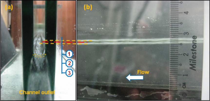
Given the narrow channel, water surface tension yielded a concave surface profile in the
lateral direction [see Fig. 3(a)]. From the observation point (side view), the water surface
appeared to be a triple-line, i.e., two bright lines [lines 1 and 3, see Fig. 3(b)] and a dark line in
the middle (line 2). Line No. 1 was induced by the light scattered by fluctuating water on the side
walls (due to water surface tension). Line 3 was caused by the light penetrating into the flow
through the fluctuating water surface, which visualized the lower part of the concave surface
profile. Line 2 represents the image of the channel bottom (which was made from black Perspex)
being reflected by the curved side of the water surface profile (acting like a convex mirror). With
those observations, the actual water level was taken as the elevation at the lower edge of line 2.
5
Such measurements were further verified using point gage readings taken at accessible points
across the channel. For most of the cases, the sharp edges of line 2 existed and, thus, the
water level reading could be made with sub-millimeter accuracy. For the case of large Froude
numbers, the water surface was subject to shock-like disturbances, and flow depth was taken
as an average over a duration of about 30 seconds. This value was also checked by the image
captured with a CCD camera that was positioned at the reading elevation.
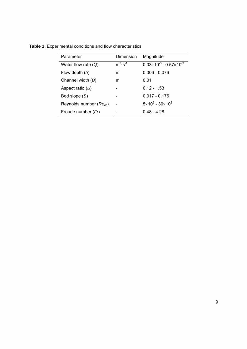
In total, 200 tests were completed for a wide range of experimental conditions, where the
flow depth h varies from 0.006 to 0.076 m, the aspect ratio α varies from 0.12 to 1.53, the bed
slope S varies from 0.017 to 0.176, the Reynolds number varies from 5×10³ to 3×10⁴, and the
Froude number varies from 0.48 to 4.28. The flow characteristics are summarized in Table 1
and the data are listed in Error! Reference source not found..
Comparisons
A comparison was first made between the friction factor f estimated from flow measurements, fe,
and the prediction made using Eq. (1), denoted the computed friction factor, fc. fe was calculated
from the flow shear velocity * hu gR S= and the cross-sectional average velocity V = Q/(B⋅h), as
( )2 2*8 / 8 /e hf u V gR S V= = (3)
where g is the gravitational acceleration, Rh = B⋅h/(B+2h) is the hydraulic radius, and S is the
energy slope that is the bed slope for steady, uniform flow. The goodness of agreement was
assessed using the relative prediction error,
100(%)c e
e
f fprediction error
f−
= × (4)
6
As shown in Fig. 4, the computed friction factors generally agree with the measurements,
in spite of some slight underestimates. The average prediction error is 1.32%. This level of
deviation is deemed acceptable, since the difference was within the measurement errors.
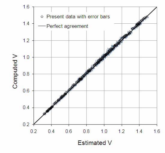
Second, fc was also used to compute the average flow velocity = 8c h cV gR S f . This
predicted velocity is then compared with the cross-sectional average velocity Vm calculated as
Q/(B⋅h). The results are plotted in Fig. 5 and show good agreement.
The error bars presented in Figs. 4 and 5 were estimated as follows. First, the errors (δ)
of the component parameters that were directly measured (i.e. the precisions of these
measurements) were evaluated. They are δQ = 0.001 l/s; δB = 0.1 mm; δh = 0.2 mm; δS =
0.025°; and δT = 0.1°C. For composite quantities, f and V, that depended on the component
parameters and were indirectly measured, their errors were estimated with the errors of all
component parameters. Since f = 8gRhS/V2, where Rh=Bh/(B+2h) and V = Q/(Bh), applying the
theory of errors (Herschy 2009), it can be shown that
1/22 2 2( ) ( ) ( ) ( )u V u Q u B u h⎡ ⎤= + +⎣ ⎦ (4)
1/22 2 2 2( ) 10 ( ) 10 ( ) 4 ( ) ( )u f u B u h u Q u S⎡ ⎤= + + +⎣ ⎦
(5)
where u(x)= 100·δx/x stands for the percentage error of quantity x. From the measurements, the
percentage errors of Q, B, h, and S were calculated for each test. With those values, the
percentage errors of V and f were then evaluated using Eqs. (4) and (5), respectively. The
average percentage error of f is 6.09% and that of V is 2.05%.
7
Conclusions
In this study, a series of experiments were conducted for steady uniform open-channel flows to
validate the formula previously proposed by Cheng et al. (2011) for evaluating smooth channel
resistance for the case of low aspect ratios. Comparisons show that the predicted friction factor
and mean flow velocity agree well with the values derived from the measurements. Together
with the results in Cheng et al. (2011), the results of both studies have verified that the proposed
formula is applicable for flows with the aspect ratio ranging from 0.12 to 15, Reynolds number
ranging from 5×10³ to 5.4×10⁵, and Froude number ranging from 0.24 to 4.28. This suggests
that the proposed formula is applicable for both wide and narrow open-channels.
References
Cheng, N. S., Nguyen, H. T., Zhao, K., and Tang, X. (2011). “Evaluation of flow resistance in
smooth rectangular open-channels with Modified Prandtl Friction Law.” Journal of Hydraulic
Engineering, ASCE, 137(4), 441-450.
Herschy, R. W. (2009). Streamflow Measurement, Routledge, London ; New York.
Knight, D. W., Demetriou, J. D., and Hamed, M. E. (1984). "Boundary shear in smooth
rectangular channels." Journal of Hydraulic Engineering, ASCE, 110(4), 405-422.
Montes, S. (1998). Hydraulics of open channel flow, ASCE press, Reston, VA.
Tracy, H. J., and Lester, C. M. (1961). "Resistance coefficients and velocity distribution, smooth
rectangular channel." U.S. Geological Survey Water-Supply Paper No. 1592-A.
8
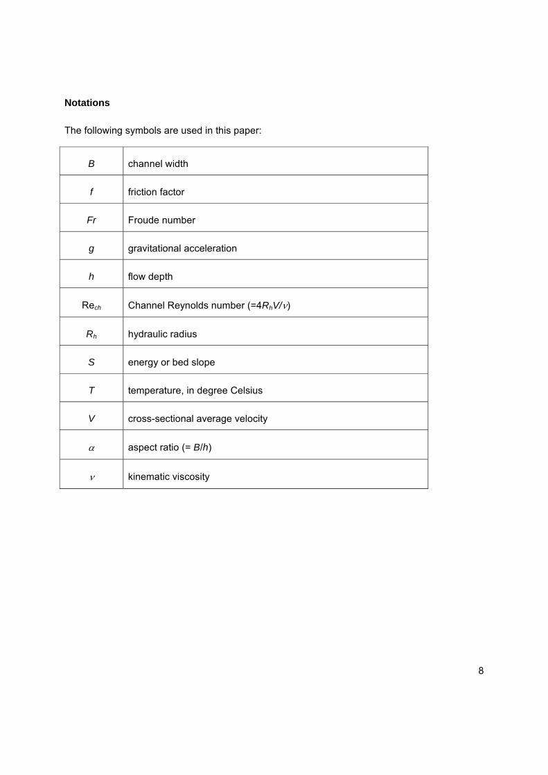
Notations
The following symbols are used in this paper:
B channel width
f friction factor
Fr Froude number
g gravitational acceleration
h flow depth
Rech Channel Reynolds number (=4RhV/ν)
Rh hydraulic radius
S energy or bed slope
T temperature, in degree Celsius
V cross-sectional average velocity
α aspect ratio (= B/h)
ν kinematic viscosity
9
Table 1. Experimental conditions and flow characteristics
Parameter Dimension Magnitude
Water flow rate (Q) m3·s-1 0.03×10⁻³ - 0.57×10⁻³
Flow depth (h) m 0.006 - 0.076
Channel width (B) m 0.01
Aspect ratio (α) - 0.12 - 1.53
Bed slope (S) - 0.017 - 0.176
Reynolds number (Rech) - 5×10³ - 30×103
Froude number (Fr) - 0.48 - 4.28
10
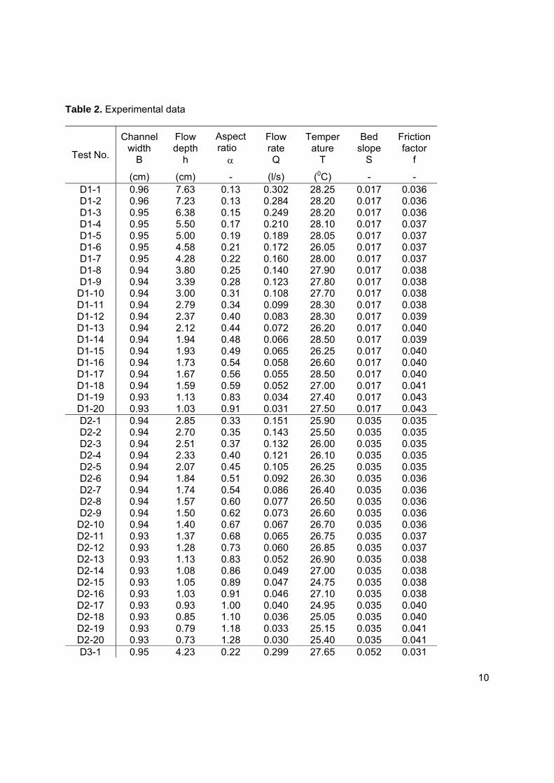
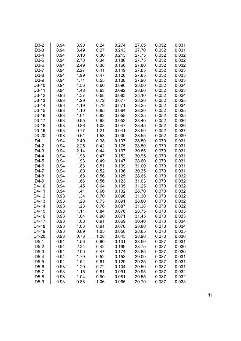
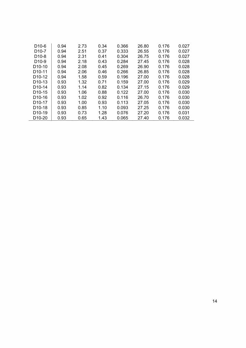
Table 2. Experimental data
Test No.
Channel width
B
Flow depth
h
Aspect ratio� α
Flow rate Q
Temperature
T
Bed slope
S
Friction factor
f
(cm) (cm) - (l/s) (0C) - - D1-1 0.96 7.63 0.13 0.302 28.25 0.017 0.036 D1-2 0.96 7.23 0.13 0.284 28.20 0.017 0.036 D1-3 0.95 6.38 0.15 0.249 28.20 0.017 0.036 D1-4 0.95 5.50 0.17 0.210 28.10 0.017 0.037 D1-5 0.95 5.00 0.19 0.189 28.05 0.017 0.037 D1-6 0.95 4.58 0.21 0.172 26.05 0.017 0.037 D1-7 0.95 4.28 0.22 0.160 28.00 0.017 0.037 D1-8 0.94 3.80 0.25 0.140 27.90 0.017 0.038 D1-9 0.94 3.39 0.28 0.123 27.80 0.017 0.038
D1-10 0.94 3.00 0.31 0.108 27.70 0.017 0.038 D1-11 0.94 2.79 0.34 0.099 28.30 0.017 0.038 D1-12 0.94 2.37 0.40 0.083 28.30 0.017 0.039 D1-13 0.94 2.12 0.44 0.072 26.20 0.017 0.040 D1-14 0.94 1.94 0.48 0.066 28.50 0.017 0.039 D1-15 0.94 1.93 0.49 0.065 26.25 0.017 0.040 D1-16 0.94 1.73 0.54 0.058 26.60 0.017 0.040 D1-17 0.94 1.67 0.56 0.055 28.50 0.017 0.040 D1-18 0.94 1.59 0.59 0.052 27.00 0.017 0.041 D1-19 0.93 1.13 0.83 0.034 27.40 0.017 0.043 D1-20 0.93 1.03 0.91 0.031 27.50 0.017 0.043 D2-1 0.94 2.85 0.33 0.151 25.90 0.035 0.035 D2-2 0.94 2.70 0.35 0.143 25.50 0.035 0.035 D2-3 0.94 2.51 0.37 0.132 26.00 0.035 0.035 D2-4 0.94 2.33 0.40 0.121 26.10 0.035 0.035 D2-5 0.94 2.07 0.45 0.105 26.25 0.035 0.035 D2-6 0.94 1.84 0.51 0.092 26.30 0.035 0.036 D2-7 0.94 1.74 0.54 0.086 26.40 0.035 0.036 D2-8 0.94 1.57 0.60 0.077 26.50 0.035 0.036 D2-9 0.94 1.50 0.62 0.073 26.60 0.035 0.036
D2-10 0.94 1.40 0.67 0.067 26.70 0.035 0.036 D2-11 0.93 1.37 0.68 0.065 26.75 0.035 0.037 D2-12 0.93 1.28 0.73 0.060 26.85 0.035 0.037 D2-13 0.93 1.13 0.83 0.052 26.90 0.035 0.038 D2-14 0.93 1.08 0.86 0.049 27.00 0.035 0.038 D2-15 0.93 1.05 0.89 0.047 24.75 0.035 0.038 D2-16 0.93 1.03 0.91 0.046 27.10 0.035 0.038 D2-17 0.93 0.93 1.00 0.040 24.95 0.035 0.040 D2-18 0.93 0.85 1.10 0.036 25.05 0.035 0.040 D2-19 0.93 0.79 1.18 0.033 25.15 0.035 0.041 D2-20 0.93 0.73 1.28 0.030 25.40 0.035 0.041 D3-1 0.95 4.23 0.22 0.299 27.65 0.052 0.031
11
D3-2 0.94 3.90 0.24 0.274 27.65 0.052 0.031 D3-3 0.94 3.49 0.27 0.243 27.70 0.052 0.031 D3-4 0.94 3.10 0.30 0.213 27.75 0.052 0.032 D3-5 0.94 2.78 0.34 0.188 27.75 0.052 0.032 D3-6 0.94 2.49 0.38 0.166 27.80 0.052 0.032 D3-7 0.94 2.27 0.41 0.149 27.85 0.052 0.033 D3-8 0.94 1.99 0.47 0.128 27.85 0.052 0.033 D3-9 0.94 1.71 0.55 0.108 27.90 0.052 0.033
D3-10 0.94 1.56 0.60 0.096 28.00 0.052 0.034 D3-11 0.94 1.48 0.63 0.092 28.60 0.052 0.033 D3-12 0.93 1.37 0.68 0.083 28.10 0.052 0.034 D3-13 0.93 1.29 0.72 0.077 28.20 0.052 0.035 D3-14 0.93 1.19 0.79 0.071 28.25 0.052 0.034 D3-15 0.93 1.10 0.85 0.064 28.30 0.052 0.035 D3-16 0.93 1.01 0.92 0.058 28.35 0.052 0.035 D3-17 0.93 0.95 0.98 0.053 28.40 0.052 0.036 D3-18 0.93 0.86 1.08 0.047 28.45 0.052 0.036 D3-19 0.93 0.77 1.21 0.041 28.50 0.052 0.037 D3-20 0.93 0.61 1.53 0.030 28.55 0.052 0.039 D4-1 0.94 2.49 0.38 0.197 28.50 0.070 0.031 D4-2 0.94 2.25 0.42 0.175 28.50 0.070 0.031 D4-3 0.94 2.14 0.44 0.167 30.85 0.070 0.031 D4-4 0.94 1.98 0.47 0.152 30.95 0.070 0.031 D4-5 0.94 1.93 0.49 0.147 28.60 0.070 0.031 D4-6 0.94 1.83 0.51 0.139 31.00 0.070 0.031 D4-7 0.94 1.80 0.52 0.136 30.35 0.070 0.031 D4-8 0.94 1.68 0.56 0.125 28.65 0.070 0.032 D4-9 0.94 1.66 0.56 0.123 31.03 0.070 0.032
D4-10 0.94 1.45 0.64 0.105 31.25 0.070 0.032 D4-11 0.94 1.41 0.66 0.102 28.70 0.070 0.032 D4-12 0.93 1.34 0.70 0.096 31.30 0.070 0.032 D4-13 0.93 1.28 0.73 0.091 28.80 0.070 0.032 D4-14 0.93 1.23 0.76 0.087 31.38 0.070 0.032 D4-15 0.93 1.11 0.84 0.076 28.75 0.070 0.033 D4-16 0.93 1.04 0.90 0.071 31.45 0.070 0.033 D4-17 0.93 1.03 0.91 0.069 30.40 0.070 0.034 D4-18 0.93 1.03 0.91 0.070 28.80 0.070 0.034 D4-19 0.93 0.89 1.05 0.058 28.85 0.070 0.035 D4-20 0.93 0.73 1.28 0.045 28.90 0.070 0.036 D5-1 0.94 1.56 0.60 0.131 28.50 0.087 0.031 D5-2 0.94 2.24 0.42 0.199 28.75 0.087 0.030 D5-3 0.94 2.00 0.47 0.174 28.85 0.087 0.030 D5-4 0.94 1.79 0.52 0.153 29.00 0.087 0.031 D5-5 0.94 1.54 0.61 0.129 29.25 0.087 0.031 D5-6 0.93 1.29 0.72 0.104 29.50 0.087 0.031 D5-7 0.93 1.15 0.81 0.091 29.95 0.087 0.032 D5-8 0.93 1.04 0.90 0.081 29.55 0.087 0.032 D5-9 0.93 0.88 1.06 0.065 29.70 0.087 0.033

12
D5-10 0.93 0.69 1.35 0.047 29.85 0.087 0.035 D5-11 0.94 2.03 0.46 0.177 27.80 0.087 0.030 D5-12 0.93 0.66 1.41 0.045 27.90 0.087 0.036 D5-13 0.94 3.17 0.30 0.294 27.95 0.087 0.029 D5-14 0.94 2.90 0.32 0.264 28.00 0.087 0.030 D5-15 0.94 2.62 0.36 0.237 28.05 0.087 0.029 D5-16 0.94 2.17 0.43 0.191 28.10 0.087 0.030 D5-17 0.94 1.81 0.52 0.155 28.20 0.087 0.030 D5-18 0.93 1.34 0.70 0.109 28.20 0.087 0.031 D5-19 0.93 1.10 0.85 0.085 28.25 0.087 0.033 D5-20 0.93 0.80 1.17 0.058 28.40 0.087 0.034 D6-1 0.94 3.16 0.30 0.327 30.05 0.105 0.028 D6-2 0.94 2.88 0.33 0.295 30.10 0.105 0.028 D6-3 0.94 2.59 0.36 0.261 30.15 0.105 0.029 D6-4 0.94 2.45 0.38 0.243 27.10 0.105 0.029 D6-5 0.94 2.25 0.42 0.223 30.30 0.105 0.029 D6-6 0.94 2.25 0.42 0.220 27.20 0.105 0.029 D6-7 0.94 2.01 0.47 0.194 27.35 0.105 0.030 D6-8 0.94 1.95 0.48 0.189 30.40 0.105 0.029 D6-9 0.94 1.92 0.49 0.184 26.80 0.105 0.030
D6-10 0.94 1.70 0.55 0.160 26.90 0.105 0.030 D6-11 0.94 1.63 0.57 0.153 30.50 0.105 0.030 D6-12 0.94 1.58 0.59 0.146 27.40 0.105 0.030 D6-13 0.93 1.34 0.70 0.122 30.60 0.105 0.030 D6-14 0.93 1.30 0.72 0.116 27.45 0.105 0.031 D6-15 0.93 1.10 0.85 0.095 27.60 0.105 0.031 D6-16 0.93 1.02 0.92 0.087 30.70 0.105 0.032 D6-17 0.93 0.98 0.95 0.083 27.70 0.105 0.032 D6-18 0.93 0.79 1.18 0.063 27.75 0.105 0.033 D6-19 0.93 0.70 1.33 0.055 30.75 0.105 0.033 D6-20 0.93 0.70 1.33 0.053 27.00 0.105 0.035 D7-1 0.93 0.89 1.05 0.080 28.30 0.123 0.032 D7-2 0.94 2.12 0.44 0.227 27.60 0.123 0.028 D7-3 0.94 2.37 0.40 0.258 27.70 0.123 0.028 D7-4 0.94 2.58 0.36 0.281 27.75 0.123 0.028 D7-5 0.93 0.79 1.18 0.069 28.40 0.123 0.033 D7-6 0.93 0.66 1.41 0.055 28.50 0.123 0.034 D7-7 0.94 1.90 0.49 0.199 27.90 0.123 0.029 D7-8 0.94 1.75 0.54 0.181 27.95 0.123 0.029 D7-9 0.94 1.56 0.60 0.158 28.00 0.123 0.030
D7-10 0.94 1.41 0.66 0.140 28.00 0.123 0.030 D7-11 0.93 1.29 0.72 0.127 28.05 0.123 0.030 D7-12 0.93 1.10 0.85 0.104 28.10 0.123 0.031 D7-13 0.93 1.20 0.78 0.117 28.20 0.123 0.030 D7-14 0.93 1.00 0.93 0.093 28.30 0.123 0.031 D7-15 0.94 2.97 0.32 0.331 27.40 0.123 0.028 D7-16 0.94 2.57 0.37 0.281 27.50 0.123 0.028 D7-17 0.94 2.16 0.43 0.229 27.55 0.123 0.029

13
D7-18 0.94 1.69 0.55 0.174 27.65 0.123 0.029 D7-19 0.94 1.42 0.66 0.141 27.70 0.123 0.030 D7-20 0.93 1.15 0.81 0.110 27.75 0.123 0.031 D8-1 0.94 4.16 0.23 0.512 22.00 0.141 0.028 D8-2 0.94 3.84 0.25 0.466 22.25 0.141 0.028 D8-3 0.94 3.64 0.26 0.442 22.35 0.141 0.028 D8-4 0.94 3.27 0.29 0.396 25.20 0.141 0.027 D8-5 0.94 3.23 0.29 0.386 22.45 0.141 0.028 D8-6 0.94 2.94 0.32 0.348 25.50 0.141 0.028 D8-7 0.94 2.73 0.34 0.321 25.75 0.141 0.028 D8-8 0.94 2.44 0.38 0.284 25.80 0.141 0.028 D8-9 0.94 2.25 0.42 0.259 26.00 0.141 0.028
D8-10 0.94 1.93 0.49 0.216 25.75 0.141 0.029 D8-11 0.94 1.88 0.50 0.210 25.25 0.141 0.029 D8-12 0.93 1.35 0.69 0.143 26.20 0.141 0.030 D8-13 0.93 1.33 0.70 0.139 23.80 0.141 0.031 D8-14 0.93 1.05 0.89 0.106 26.30 0.141 0.031 D8-15 0.93 0.95 0.98 0.093 26.45 0.141 0.031 D8-16 0.93 0.84 1.11 0.080 26.50 0.141 0.032 D8-17 0.93 0.80 1.17 0.075 25.10 0.141 0.033 D8-18 0.93 0.72 1.30 0.066 26.70 0.141 0.032 D8-19 0.93 0.67 1.39 0.060 25.45 0.141 0.033 D8-20 0.93 0.64 1.46 0.056 26.60 0.141 0.034 D9-1 0.95 4.31 0.22 0.565 22.80 0.158 0.027 D9-2 0.94 4.14 0.23 0.541 22.50 0.158 0.028 D9-3 0.94 3.78 0.25 0.488 22.60 0.158 0.028 D9-4 0.94 2.50 0.38 0.312 26.80 0.158 0.028 D9-5 0.94 3.19 0.30 0.405 22.50 0.158 0.028 D9-6 0.94 2.86 0.33 0.358 22.20 0.158 0.028 D9-7 0.94 1.67 0.56 0.194 22.00 0.158 0.030 D9-8 0.93 0.98 0.95 0.103 24.00 0.158 0.031 D9-9 0.94 2.82 0.33 0.360 26.90 0.158 0.027
D9-10 0.93 1.27 0.74 0.142 25.10 0.158 0.030 D9-11 0.93 1.12 0.83 0.123 25.40 0.158 0.030 D9-12 0.93 1.04 0.90 0.112 25.50 0.158 0.030 D9-13 0.93 0.91 1.03 0.095 25.65 0.158 0.031 D9-14 0.93 0.78 1.20 0.077 25.80 0.158 0.032 D9-15 0.93 0.64 1.46 0.061 25.90 0.158 0.032 D9-16 0.94 1.41 0.66 0.161 26.00 0.158 0.029 D9-17 0.94 3.13 0.30 0.405 26.70 0.158 0.027 D9-18 0.94 4.07 0.23 0.541 26.50 0.158 0.027 D9-19 0.94 3.92 0.24 0.519 26.50 0.158 0.027 D9-20 0.94 3.64 0.26 0.478 26.50 0.158 0.027 D10-1 0.94 3.69 0.26 0.517 26.45 0.176 0.026 D10-2 0.94 3.41 0.28 0.471 26.45 0.176 0.027 D10-3 0.94 3.23 0.29 0.442 26.75 0.176 0.027 D10-4 0.94 3.10 0.30 0.423 26.45 0.176 0.027 D10-5 0.94 2.76 0.34 0.371 26.50 0.176 0.027
14
D10-6 0.94 2.73 0.34 0.366 26.80 0.176 0.027 D10-7 0.94 2.51 0.37 0.333 26.55 0.176 0.027 D10-8 0.94 2.31 0.41 0.304 26.75 0.176 0.027 D10-9 0.94 2.18 0.43 0.284 27.45 0.176 0.028
D10-10 0.94 2.08 0.45 0.269 26.90 0.176 0.028 D10-11 0.94 2.06 0.46 0.266 26.85 0.176 0.028 D10-12 0.94 1.58 0.59 0.196 27.00 0.176 0.028 D10-13 0.93 1.32 0.71 0.159 27.00 0.176 0.029 D10-14 0.93 1.14 0.82 0.134 27.15 0.176 0.029 D10-15 0.93 1.06 0.88 0.122 27.00 0.176 0.030 D10-16 0.93 1.02 0.92 0.116 26.70 0.176 0.030 D10-17 0.93 1.00 0.93 0.113 27.05 0.176 0.030 D10-18 0.93 0.85 1.10 0.093 27.25 0.176 0.030 D10-19 0.93 0.73 1.28 0.076 27.20 0.176 0.031 D10-20 0.93 0.65 1.43 0.065 27.40 0.176 0.032