
Flexlift INOX mini - Varimixer
32
INSTRUCTION MANUAL SERIAL NUMBER: ____________________ Varimixer A/S Kirkebjerg Søpark 6 DK-2605 Brøndby Denmark P: +45 4344 2288 E: [email protected] www.varimixer.com SAP nr. 20060-1710 Version 1.1 UK Original language "English"
-
Upload
khangminh22 -
Category
Documents
-
view
0 -
download
0
Transcript of Flexlift INOX mini - Varimixer

INSTRUCTION MANUAL
SERIAL NUMBER: ____________________
Varimixer A/SKirkebjerg Søpark 6DK-2605 BrøndbyDenmark
P: +45 4344 2288E: [email protected]
SAP nr. 20060-1710Version 1.1 UKOriginal language "English"

EC - DECLARATION OF CONFORMITYMachinery Directive 2006/42/EC Annex II A
Manufacturer and party responsible for compiling technical documentation:
Company name:Address:Postal code:Phone number:
Hovmand A/SSandvadsvej 15DK-4600 Køge, Denmark+ 45 57 83 33 00www.hovmand.com
- hereby declare that the machine:
Designation:Type identification number:Serial number:
Mobile battery-powered lifterFlexlift INOXmini_______________________
- is manufactured in accordance with the Machinery Directive 2006/42/EC Annex II A.
The following directives and standards as well as technical reports have been applied, insofar as they havebeen found to be wholly or partly relevant in relation to the construction and design of the machine:
Directives: 2014/30/EC2014/35/EC2011/65/EC
Standards: EN/ISO12100: 2011EN/ISO/TR 14121-2: 2012EN 60204-1: 2016EN/IEC 63000: 2018EN/ISO3691-5: 2015DS/EN ISO20607: 2019
Authorisation of HOVMAND A/S, to prepare technical documentation and communicate information about thedevice, in response to any sufficiently motivated request from state authorities:
Køge 15/12-2021
Søren HovmandManaging DirectorHovmand A/S

DECLARATION OF CONFORMITYSupply of Machinery Safety Regulations 2008
Manufacturer and party responsible for compiling technical documentation:
Company name:Address:Postal code:Phone number:
Hovmand A/SSandvadsvej 15DK-4600 Køge, Denmark+ 45 57 83 33 00www.hovmand.com
- hereby declare that the machine:
Designation:Type identification number:Serial number:
Mobile battery-powered lifterFlexlift INOXmini_______________________
- is manufactured in accordance with the Supply of Machinery Safety Regulations 2008.
The following directives and standards as well as technical reports have been applied, insofar as they havebeen found to be wholly or partly relevant in relation to the construction and design of the machine:
Directives: Electromagnetic Compatibility Regulations 2016Electrical Equipment Safety Regulations 2016RoHS Regulations 2012:GB
Standards: BS/EN/ISO12100: 2011ISO/TR 14121-2: 2012BS/EN 60204-1: 2016BS/EN/IEC 63000: 2018BS/EN/ISO3691-5: 2015BS/EN ISO20607: 2019
Authorisation of HOVMAND A/S, to prepare technical documentation and communicate information about thedevice, in response to any sufficiently motivated request from state authorities:
Køge 15/12-2021
Søren HovmandManaging DirectorHovmand A/S

Table of content
1 Typographic convention 52 Specifications 63 General safety precautions during use 74 Exception of liability 85 Residual risks 86 Operating the lifter 96.1 Remote control - QC3 - 8 buttons 96.2 Shipping 96.3 Safety areas and distance 107 Construction and Materials 118 Batteries and chargers 129 Lifting equipment 139.1 Quick Clamp with turning unit - QC3 139.2 Light Indicator 149.3 Adjustments 149.4 Adjusting speed and Amps for gripping unit 1410 Maintenance and Inspection 1511 Disposal 1512 Cleaning instructions 1613 Resolving faults 1714 Electrical chart 1815 Spare parts 1915.1 Flexlift INOX mini - Complete 1915.2 Mast - Complete 2015.3 Mast 2115.4 Control box: 2215.5 Turning unit 2315.6 Tool 2415.7 leg set 2516 Dimensions 2616.1 Lifter dimension 2616.2 Tool dimensions 2717 Annual inspection 28

5
1 Typographic conventionThe following cautionary symbols may be used in the manual and / or on the lift.
Warning!This pictogram draws attention to the risk of personal injury.
Warning!This pictogram draws attention to the risk of personal injury.l There is a risk of getting your fingers crushed.
Warning!This pictogram draws attention to the risk of personal injury.l The lifter must not be used for lifting persons.
Warning!This pictogram draws attention to the risk of personal injury.l There should be no body parts below or near the lifting tool whenoperated up or down.
Warning!This pictogram draws attention to the risk of personal injury.l There should be no body parts on top of the front legs steel profile,when the lift is elevated or operated.

6
2 SpecificationsFlexlift INOX mini
Weight (kg) 83Height (mm) 1524Max load (kg) 50kgLifting speed (normal speed) 100 - 125 mm/sProtection class IP66Batteries 24V,18AHCharger 90 - 264V 47/63Hz – 2,5 AmpsCharging time 6 hours (80%) 8 hours (100%)Sound pressure level ≤ 70 Db(A)Vibration strength ≤ 2,5 m/s²

7
3 General safety precautions during useThe following guidelines must be observed and followed when using a lift, to prevent personal injury:
l Under no circumstances should the lift elevate more than specified on the label.l It is of most importance, due to personal safety, that the specified weight, load position,and height are respected and that the lift is not overloaded.
l The lift must not be used for lifting persons or live animals.
l No body parts near the sledge or tool at the mast or other lifting equipment when operatedup/down.
l Secure that there is no person below the load, tool and lift when operated.
l There should be no body parts on top of the front legs steel profile, when the lift is elevatedor operated.
l Only one person must operate the lift at a time.l The user must read and understand these instructions or must have them explained tothem before using the lifter.
l Only use the lift when operated on a hard-levelled surface during lifting or transportingloads.
l When transporting a cargo, the load should be lowered to the lowest possible position andsecured in order to ensure that the cargo cannot slide.
l Always secure the cargo on the lift when moving.l Not in use or storing, always ensure that the sledge is lowered to the lowest possible pos-ition and is free of any items or cargo.
l Operate and store in a clean, dry location with temperature from +5 °C to +40 °C.l Make sure that the tool is firmly attached to the sledge and no slack occurs in the bolt con-nection.
l The lifter is to be controlled at least once a year or according to laws, regulations, dir-ectives, working conditions and experience. The control shall be performed by the man-ufacturer or a skilled technician. Please check your local requirements.
l Do not lift or handle open containers containing corrosive fluids, harmful to people ifspilled.
l Industrial or commercial use only.l Indoor use only.l Do not use the lifter in explosive or flammable hazard environment.l Do not use or store in a corrosive environment.
8
4 Exception of liabilityl Hovmand cannot be held responsible for any modifications on the lift or attached equipment, not author-ized by Hovmand.
l Do only use original spare parts, otherwise Hovmand cannot be held liable for the function and safety ofthe lift.
l The lifter must only be serviced by a qualified technician, otherwise Hovmand cannot be held liable forthe function and safety of the lift.
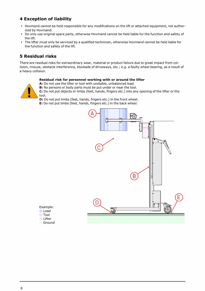
5 Residual risksThere are residual risks for extraordinary wear, material or product failure due to great impact from col-lision, misuse, obstacle interference, blockade of driveways, etc.; e.g. a faulty wheel bearing, as a result ofa heavy collision.
Residual risk for personnel working with or around the lifterA: Do not use the lifter or tool with unstable, unbalanced load.B: No persons or body parts must be put under or near the tool.C: Do not put objects or limbs (feet, hands, fingers etc.) into any opening of the lifter or thetool.D: Do not put limbs (feet, hands, fingers etc.) in the front wheel.E: Do not put limbs (feet, hands, fingers etc.) in the back wheel.
Example:n Loadn Tooln Liftern Ground

9
6 Operating the lifter
6.1 Remote control - QC3 - 8 buttons
The remote control has 8 buttons, which operate as follows:
The remote control symbols
Button no. / Function Description Symbol Comments
1 Lifting The lifter will lift while the button ispressed ⇧ Normal
speed
2 Lowering The lifter will lower while the button ispressed ⇩ Normal
speed
3 Turning left (counter clockwise) ⟲4 Turning right (clockwise) ⟳5+6 Manipulator reduces / grips 2 buttons must be pressed at the same
time 17+8 Manipulator expands / eases grip-ping
2 buttons must be pressed at the sametime 2
6.2 Shipping
When shipping the lifter:l The sledge must be lowered to the lowest possible position and be free of any items orcargo.
l Fasten the lifter securely during transport.

10
6.3 Safety areas and distance
Safety when operating the toolThe operator must ensure that the tool is clear of obstacles before lifting, lowering or rotating.The operator must warn other personnel before lifting, lowering, rotating or using the tool.When lifting, lowering, rotating or using the tool, the operator must:- stand behind the wheels of the lifter as illustrated below (n A).- ensure that all other personnel are out of the danger zone as illustrated below(n B).
n Liftern Tool
n Safety area for operatorA Safety distance = 1500 mm
n Safety area for other personnelB safety distance = 3000 mm

11
7 Construction and MaterialsAll materials are suitable for use in pharma and food industry.
Part MaterialMast Electro polished stainless steel (1.4301 / AISI 304)Handle Electro polished stainless steel (1.4301 / AISI 304)Sledge Electro polished stainless steel (1.4301 / AISI 304)Front cover for mast Electro polished stainless steel (1.4301 / AISI 304)Remote Polyamide 6
Wheel frame Electro polished stainless steel (1.4301 / AISI 304)Front wheels PolyurethaneBack wheels Polyamide and Polyurethane
12
8 Batteries and chargersBefore using the batteriesNew batteries should always be fully charged prior to using.
Charge the battery pack dailyThe battery pack must be charged daily as total discharge can damage the batteries or shortentheir lifespan.
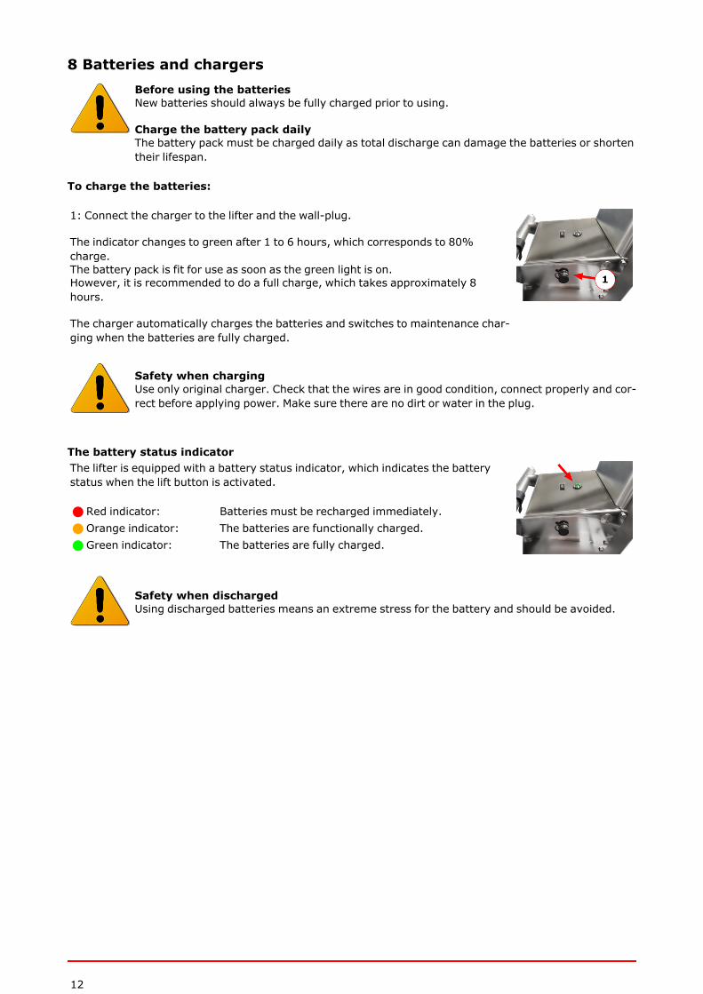
To charge the batteries:
1: Connect the charger to the lifter and the wall-plug.
The indicator changes to green after 1 to 6 hours, which corresponds to 80%charge.The battery pack is fit for use as soon as the green light is on.However, it is recommended to do a full charge, which takes approximately 8hours.
The charger automatically charges the batteries and switches to maintenance char-ging when the batteries are fully charged.
Safety when chargingUse only original charger. Check that the wires are in good condition, connect properly and cor-rect before applying power. Make sure there are no dirt or water in the plug.
The battery status indicatorThe lifter is equipped with a battery status indicator, which indicates the batterystatus when the lift button is activated.
n Red indicator: Batteries must be recharged immediately.n Orange indicator: The batteries are functionally charged.n Green indicator: The batteries are fully charged.
Safety when dischargedUsing discharged batteries means an extreme stress for the battery and should be avoided.
13
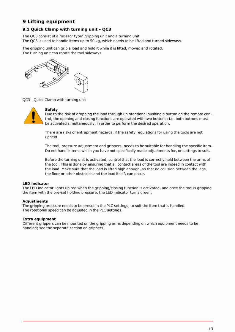
9 Lifting equipment9.1 Quick Clamp with turning unit - QC3The QC3 consist of a “scissor type” gripping unit and a turning unit.The QC3 is used to handle items up to 50 kg, which needs to be lifted and turned sideways.
The gripping unit can grip a load and hold it while it is lifted, moved and rotated.The turning unit can rotate the tool sideways.
QC3 - Quick Clamp with turning unit
SafetyDue to the risk of dropping the load through unintentional pushing a button on the remote con-trol, the opening and closing functions are operated with two buttons; i.e. both buttons mustbe activated simultaneously, in order to perform the desired operation.
There are risks of entrapment hazards, if the safety regulations for using the tools are notupheld.
The tool, pressure adjustment and grippers, needs to be suitable for handling the specific item.Do not handle items which you have not specifically made adjustments for, or settings to suit.
Before the turning unit is activated, control that the load is correctly held between the arms ofthe tool. This is done by ensuring that all contact areas of the tool are indeed in contact withthe load. Make sure that the load is lifted high enough, so that no collision between the legs,the floor or other obstacles and the load itself, can occur.
LED indicatorThe LED indicator lights up red when the gripping/closing function is activated, and once the tool is grippingthe item with the pre-set holding pressure, the LED indicator turns green.
AdjustmentsThe gripping pressure needs to be preset in the PLC settings, to suit the item that is handled.The rotational speed can be adjusted in the PLC settings.
Extra equipmentDifferent grippers can be mounted on the gripping arms depending on which equipment needs to behandled; see the separate section on grippers.
14
9.2 Light IndicatorThe LED indicator lights red during the Gripping / closing function, when the tool has gripped to the presetholding pressure, the LED indicator lights green.
9.3 AdjustmentsThe gripping pressure needs to be preset in the PLC settings, to suit the item that is handled.The rotational speed can be adjusted in the PLC settings.
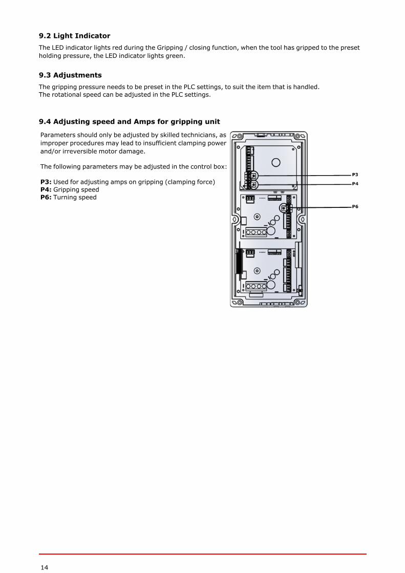
9.4 Adjusting speed and Amps for gripping unit
Parameters should only be adjusted by skilled technicians, asimproper procedures may lead to insufficient clamping powerand/or irreversible motor damage.
The following parameters may be adjusted in the control box:
P3: Used for adjusting amps on gripping (clamping force)P4: Gripping speedP6: Turning speed
15
10 Maintenance and InspectionAll Hovmand products are designed for minimum maintenance, however some safety checks and pro-cedures are required.
Hovmand strongly recommends the following checks be carried out on a daily basis and before using the lift.Ensure that the lift is functioning as intended. If in doubt, do not use.l The lifter must be free of dirt or debris which could affect safe operationl Ensure all labels are present, without damage and are readable.l Ensure no sign of wear, miss sounds or visual defects.l Ensure bolts, nuts and rivets should not be loose.l Ensure correct operation of the brakes.l Ensure the lifter moves freely on its wheel and the castors.l Ensure control unit are in working order.
The yearly maintenance must be performed by a qualified technician.
The critical components listed below, must be replaced with the intervals stated, to make sure that the lifteris in safe, operational condition.
Critical components:
Please contact Hovmand for instruction on how to replace critical components.
Cam beltl Replace when / if any of the below points occur:
l Any sign of wear, visual cracks, or miscolour.l Under normal use (Use < 20 lifts per day, in average over a year), replace after 8 years.l Under intensive use (Use > 20 lifts per day, in average over a year), replace after 4 years.
One way bearingl Replace when / if any of the below points occur:
l Any sign of wear, miss sounds or visual defects.l Under normal use (Use < 20 lifts per day in average over a year), replace after 8 years.l Under intensive use (Use > 20 lifts per day, in average over a year), replace after 4 years.
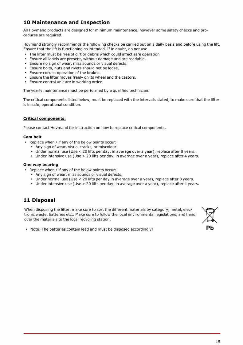
11 Disposal
When disposing the lifter, make sure to sort the different materials by category, metal, elec-tronic waste, batteries etc.. Make sure to follow the local environmental legislations, and handover the materials to the local recycling station.
l Note: The batteries contain lead and must be disposed accordingly!
16
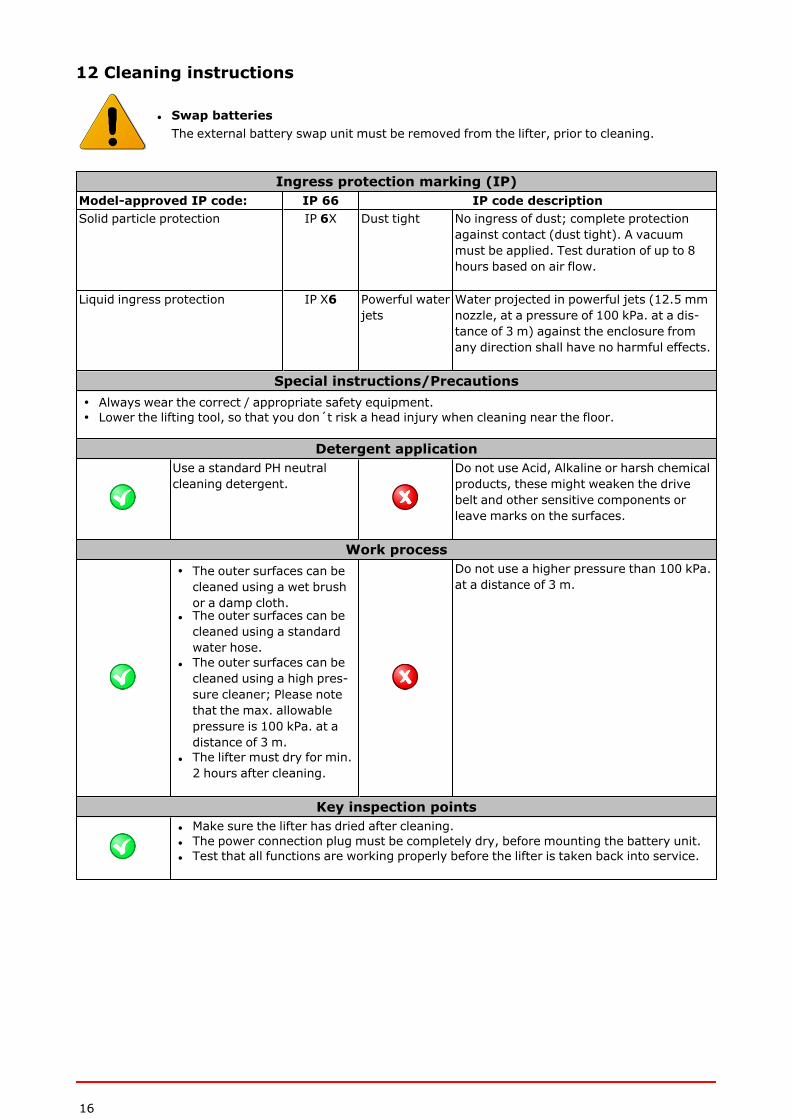
12 Cleaning instructions
l Swap batteriesThe external battery swap unit must be removed from the lifter, prior to cleaning.
Ingress protection marking (IP)Model-approved IP code: IP 66 IP code descriptionSolid particle protection IP 6X Dust tight No ingress of dust; complete protection
against contact (dust tight). A vacuummust be applied. Test duration of up to 8hours based on air flow.
Liquid ingress protection IP X6 Powerful waterjets
Water projected in powerful jets (12.5 mmnozzle, at a pressure of 100 kPa. at a dis-tance of 3 m) against the enclosure fromany direction shall have no harmful effects.
Special instructions/Precautionsl Always wear the correct / appropriate safety equipment.l Lower the lifting tool, so that you don´t risk a head injury when cleaning near the floor.
Detergent applicationUse a standard PH neutralcleaning detergent.
Do not use Acid, Alkaline or harsh chemicalproducts, these might weaken the drivebelt and other sensitive components orleave marks on the surfaces.
Work processl The outer surfaces can becleaned using a wet brushor a damp cloth.
l The outer surfaces can becleaned using a standardwater hose.
l The outer surfaces can becleaned using a high pres-sure cleaner; Please notethat the max. allowablepressure is 100 kPa. at adistance of 3 m.
l The lifter must dry for min.2 hours after cleaning.
Do not use a higher pressure than 100 kPa.at a distance of 3 m.
Key inspection pointsl Make sure the lifter has dried after cleaning.l The power connection plug must be completely dry, before mounting the battery unit.l Test that all functions are working properly before the lifter is taken back into service.

17
13 Resolving faults
Fault type Check the following Solve
The timing belt jumps onthe belt wheel (the belt ismaking crackling noises)
Is the belt slack? Tighten the belt using the screws at thetop of the mast.
Is the belt worn? Replace the belt.
The belt is skewed(the belt squeaks) Is the belt running skewed in the
track on the top cam wheel?
Adjust the screw at the top of themast, on the side to which the belt isskewed.
Is the belt worn? Replace the belt.
The sledge jerks Is there dirt in the mast on whichthe sledge runs? Remove the dirt and wipe with alcohol.
Is there dirt on the sledge wheels? Remove the dirt or replace the wheels.
The lifter does not respond Check whether the item being liftedis heavier than the lift's capacity Remove the item.
Check the main fuse or the on/offbutton
Replace the main fuse or press the but-ton.
Check that the batteries arecharged Connect the charger.
The lift works very slowly Check the voltage of the batteries Connect the charger.
Check the charging frequency. Doesthe light quickly change to greenwhen connected?
If the charger quickly changes togreen, it could indicate that the bat-teries should be replaced or the fuse onthe charger is broken or the mainswitch is off.
18
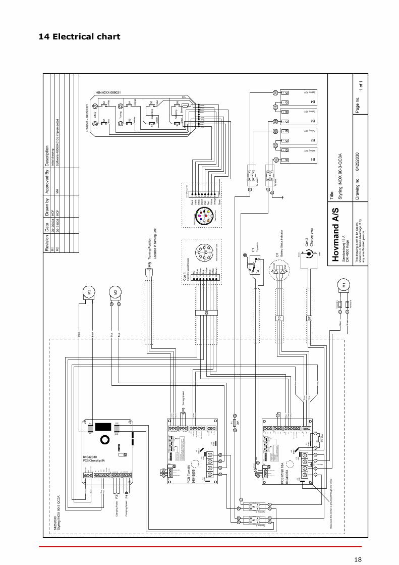
14 Electrical chart
19
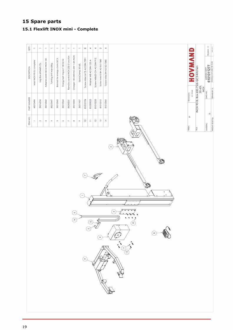
15 Spare parts15.1 Flexlift INOX mini - Complete
614
513
4
1112
3
10
71
2
8
9
ITEM
NO
.PA
RT N
UMBE
RD
ESC
RIPT
ION
QTY
.
140
0104
94M
ast I
NO
X 90
-3L
com
plet
e1
230
0162
34Le
g-Bo
x-65
0x46
5-75
s1
330
0120
62A
dap
ter p
late
QC
3/-IN
OX
130
1
440
0104
47Tu
rnin
g Un
it m
ax 6
0kg.
1
530
0120
63Br
acke
t for
ene
rgy
chai
n Q
C3
1
630
0120
64En
ergy
bel
t Im
pact
130
-3L+
M1
784
2900
31Re
mot
e co
ntro
l IN
OX
200
3 fu
nctio
n1
830
0100
04C
harg
er 1
00-2
40V
AC
-24V
1,8
A IN
OX
1
930
0174
57Q
uick
Cla
mp
30-6
0L1
1081
0101
94Sc
rew
M6x
16 C
S A
2 D
IN 7
991
8
1181
0300
25W
ashe
r M8
A2
DIN
125
A4
1281
0102
33Sc
rew
M8x
20 C
H A
2 D
IN 9
124
1381
0103
15Sc
rew
M4x
10 B
H A
2 IS
O 7
380
2
1481
0103
43Sc
rew
M3x
6 BH
A2
ISO
738
04
MA
TERI
AL:
Revi
sion:
2
INO
X 90
-3L
Box-
650-
75ds
QC
3-Ki
tche
n
6101
0112
776101011277
DRA
WN
BY:
LL
W
EIG
HT: 8
2.87
KgEP
SHEE
T 2
OF
3
DW
G N
O.
TITLE
:
FINIS
H:
INO
X30
-60L
Dat
e[yy
.mm
.dd
]:SS
Dim
ensio
ns:
+/- 5
mm
18.1
2.04
20
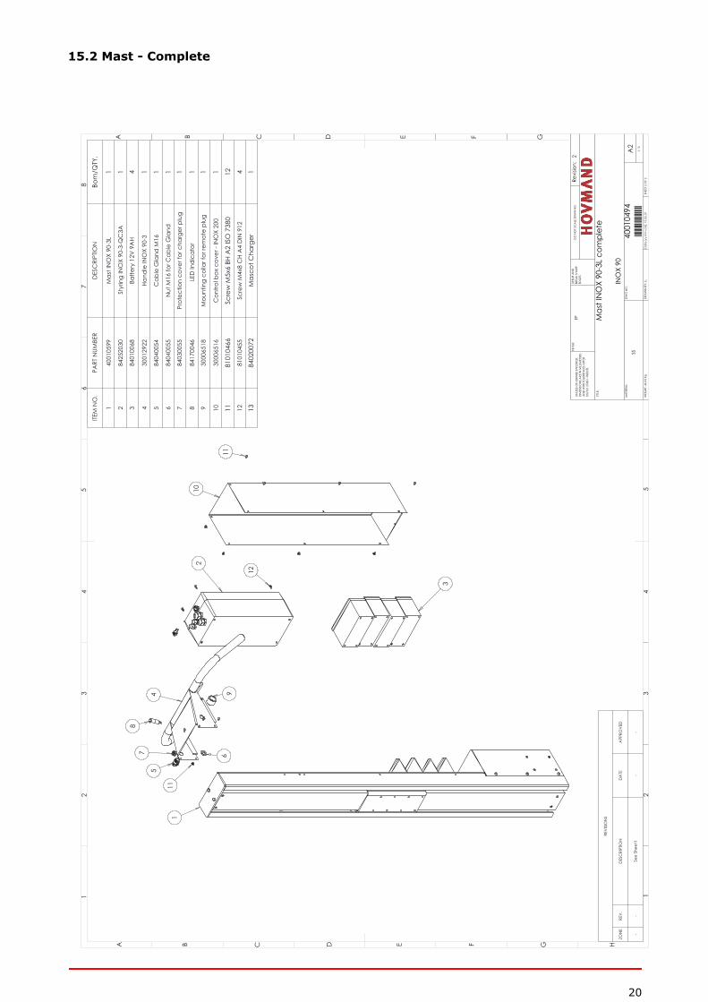
15.2 Mast - Complete
1
10
11
2
12
3
96
5
78
4
11
ITEM
NO
.PA
RT N
UMBE
RD
ESC
RIPT
ION
Bom
/QTY
.
140
0105
99M
ast I
NO
X 90
-3L
1
284
2520
30St
yrin
g IN
OX
90-3
-QC
3A1
384
0100
68Ba
ttery
12V
9A
H4
430
0129
22Ha
ndle
INO
X 90
-31
584
0400
54C
able
Gla
nd M
161
684
0400
55N
ut M
16 fo
r Cab
le G
land
17
8403
0055
Prot
ectio
n co
ver f
or c
harg
er p
lug
1
884
1700
46LE
D In
dic
ator
1
930
0065
18M
ount
ing
colla
r for
rem
ote
plug
1
1030
0065
16C
ontro
l box
cov
er -
INO
X 20
01
1181
0104
66Sc
rew
M5x
6 BH
A2
ISO
738
012
1281
0104
55Sc
rew
M4x
8 C
H A
4 D
IN 9
124
1384
0200
72M
asco
t Cha
rger
1
REV
ISIO
NS
ZON
ERE
V.
DES
CRI
PTIO
ND
ATE
APP
ROV
ED
--
See
Shee
t1-
-
A B C D E F G H
12
34
56
78
A B C D E F G
12
34
5
A2
MA
TERI
AL:
Revi
sion:
2
Mas
t IN
OX
90-3
L co
mpl
ete
4001
0494
40010494
DRA
WN
BY:
LL
W
EIG
HT: 4
6.93
Kg
EP
SS
SHEE
T 2
OF
2
1:10
DW
G N
O.
TITLE
:
DO
NO
T SC
ALE
DRA
WIN
GD
EBUR
AN
D
BREA
K SH
ARP
ED
GES
FINIS
H:UN
LESS
OTH
ERW
ISE
SPEC
IFIE
D:
DIM
ENSI
ON
S A
RE IN
MILL
IMET
ERS
AN
D W
ITH T
OLE
REN
CES
AFT
ERD
S/IS
O 2
768-
1 M
IDD
EL
INO
X 90
15.0
6.01
Dat
e[yy
.mm
.dd
]:
21
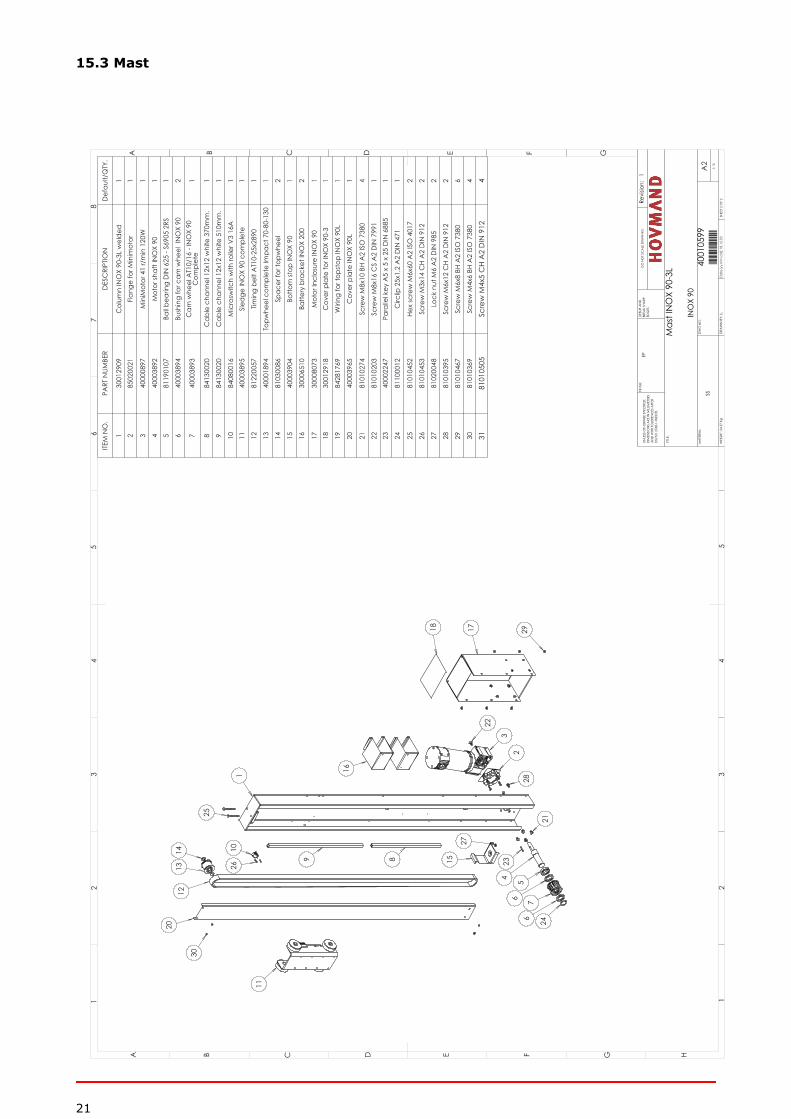
15.3 Mast
11
30
2013
1214 10
26
25
1
9 8 15
27
234 5
6 76 24
21
282
3
22
18 17 29
16
ITEM
NO
.PA
RT N
UMBE
RD
ESC
RIPT
ION
Def
ault/
QTY
.
130
0129
09C
olum
n IN
OX
90-3
L w
eld
ed1
285
0200
21Fl
ange
for M
inim
otor
1
340
0008
97M
iniM
otor
41
r/m
in 1
20W
1
440
0038
92M
otor
shaf
t IN
OX
901
581
1901
07Ba
ll bea
ring
DIN
625
- S6
905
2RS
1
640
0038
94Bu
shin
g fo
r cam
whe
el I
NO
X 90
2
740
0038
93C
am w
heel
AT1
0/16
- IN
OX
90
Com
plet
e1
884
1300
20C
able
cha
nnel
12x
12 w
hite
370
mm
.1
984
1300
20C
able
cha
nnel
12x
12 w
hite
510
mm
.1
1084
0800
16M
icro
switc
h w
ith ro
ller V
3 16
A1
1140
0038
95Sl
edge
INO
X 90
com
plet
e1
1281
2200
57Tim
ing
belt
AT1
0-25
x289
01
1340
0018
94To
pwhe
el c
ompl
ete
Impa
ct 7
0-80
-130
1
1481
0300
86Sp
acer
for t
opw
heel
2
1540
0039
04Bo
ttom
stop
INO
X 90
1
1630
0065
10Ba
ttery
bra
cket
INO
X 20
02
1730
0080
73M
otor
Incl
osur
e IN
OX
901
1830
0129
18C
over
pla
te fo
r IN
OX
90-3
1
1984
2817
69W
iring
for t
opst
op IN
OX
90L
1
2040
0039
65C
over
pla
te IN
OX
90L
1
2181
0102
74Sc
rew
M8x
10 B
H A
2 IS
O 7
380
4
2281
0102
03Sc
rew
M8x
16 C
S A
2 D
IN 7
991
123
4000
2247
Para
llel k
ey A
5 x
5 x
25 D
IN 6
885
1
2481
1000
12C
irclip
25x
1,2
A2
DIN
471
1
2581
0104
52He
x sc
rew
M6x
60 A
2 IS
O 4
017
2
2681
0104
53Sc
rew
M3x
14 C
H A
2 D
IN 9
122
2781
0200
48Lo
ck n
ut M
6 A
2 D
IN 9
852
2881
0103
95Sc
rew
M6x
12 C
H A
2 D
IN 9
122
2981
0104
67Sc
rew
M6x
8 BH
A2
ISO
738
06
3081
0103
69Sc
rew
M4x
6 BH
A2
ISO
738
04
3181
0105
05Sc
rew
M4x
5 C
H A
2 D
IN 9
124
A B C D E F G H
12
34
56
78
A B C D E F G
12
34
5
A2
MA
TERI
AL:
Revi
sion:
1
Mas
t IN
OX
90-3
L 4001
0599
40010599
DRA
WN
BY:
LL
W
EIG
HT: 2
4.57
Kg
EP
SS
SHEE
T 2
OF
2
1:10
DW
G N
O.
TITLE
:
DO
NO
T SC
ALE
DRA
WIN
GD
EBUR
AN
D
BREA
K SH
ARP
ED
GES
FINIS
H:UN
LESS
OTH
ERW
ISE
SPEC
IFIE
D:
DIM
ENSI
ON
S A
RE IN
MILL
IMET
ERS
AN
D W
ITH T
OLE
REN
CES
AFT
ERD
S/IS
O 2
768-
1 M
IDD
EL
INO
X 90
18.1
2.03
D
ate[
yy.m
m.d
d]:
22
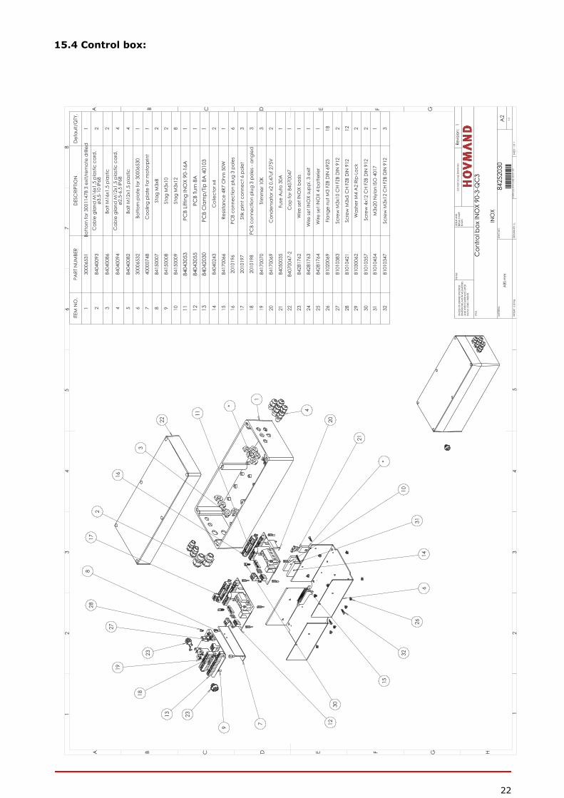
15.4 Control box:
2817
2
16
3
22
11
*
1
4
20
21
*
10
3114
626
32
15
30127
9
13
18
1927
8
23
23
ITEM
NO
.PA
RT N
UMBE
RD
ESC
RIPT
ION
Def
ault/
QTY
.
130
0065
31Bo
ttom
for 3
0011
478
3 ex
it/re
mot
e d
rille
d1
284
0400
93C
able
gla
nd M
16x1
,5 p
last
ic c
ard
, ø3
,5-1
0 IP
682
384
0400
86Bo
lt M
16x1
,5 p
last
ic2
484
0400
94C
able
gla
nd M
12x1
,5 p
last
ic c
ard
, ø2
,5-6
,5 IP
684
584
0400
82Bo
lt M
12x1
,5 p
last
ic4
630
0065
32Bo
ttom
pla
te fo
r 300
0653
01
740
0007
48C
oolin
g pl
ate
For m
otor
prin
t1
884
1500
07St
ag M
3x8
2
984
1500
08St
ag M
3x10
2
1084
1500
09St
ag M
3x12
8
1184
0430
53PC
B Lif
ting
INO
X 90
-16A
1
1284
0430
55PC
B Tu
rn 8
A1
1384
0420
30PC
B C
lam
p/Tip
8A
401
031
1484
0402
43C
olle
ctor
x4
2
1584
1700
66Re
sista
nce
4R7
Ohm
50W
1
1620
1019
6PC
B co
nnec
tion
plug
3 p
oles
6
1720
1019
7St
ik p
rint c
onne
ct 6
pol
et3
1820
1019
8PC
B co
nnec
tion
plug
3 p
oles
- an
gled
3
1984
1700
70Tr
imm
er 1
0K3
2084
1700
69C
ond
ensa
tor x
2 0,
47uf
275
V2
2184
0500
35Fu
se A
uto
30A
1
2284
0700
47-2
Cap
for 8
4070
047
1
2384
2817
62W
ire se
t IN
OX
basis
1
2484
2817
63W
ire se
t IN
OX
supp
l. 3
exit
1
2584
2817
64W
ire se
t IN
OX
4 ba
tterie
r1
2681
0200
69Fl
ange
nut
M3
FZB
DIN
692
318
2781
0103
83Sc
rew
M3x
10 C
H FZ
B D
IN 9
122
2881
0104
21Sc
rew
M3x
5 C
H FZ
B D
IN 9
1212
2981
0300
62W
ashe
r M4
A2
Rip-
Lock
2
3081
0103
57Sc
rew
4x1
2 C
H FZ
B D
IN 9
122
3181
0104
54M
3x20
Nyl
on IS
O 4
017
1
3281
0103
47Sc
rew
M3x
12 C
H FZ
B D
IN 9
123
A B C D E F G H
12
34
56
78
A B C D E F G
12
34
5
A2
MA
TERI
AL:
Revi
sion:
1
Con
trol b
ox IN
OX
90-3
-QC
3
8425
2030
84252030
DRA
WN
BY:
LL
W
EIG
HT: 2
.20
Kg
ABS
mm
SHEE
T 1 O
F 1
1:2
DW
G N
O.
TITLE
:
DO
NO
T SC
ALE
DRA
WIN
GD
EBUR
AN
D
BREA
K SH
ARP
ED
GES
FINIS
H:UN
LESS
OTH
ERW
ISE
SPEC
IFIE
D:
DIM
ENSI
ON
S A
RE IN
MILL
IMET
ERS
AN
D W
ITH T
OLE
REN
CES
AFT
ERD
S/IS
O 2
768-
1 M
IDD
EL
INO
X
20.0
1.02
D
ate[
yy.m
m.d
d]:
23
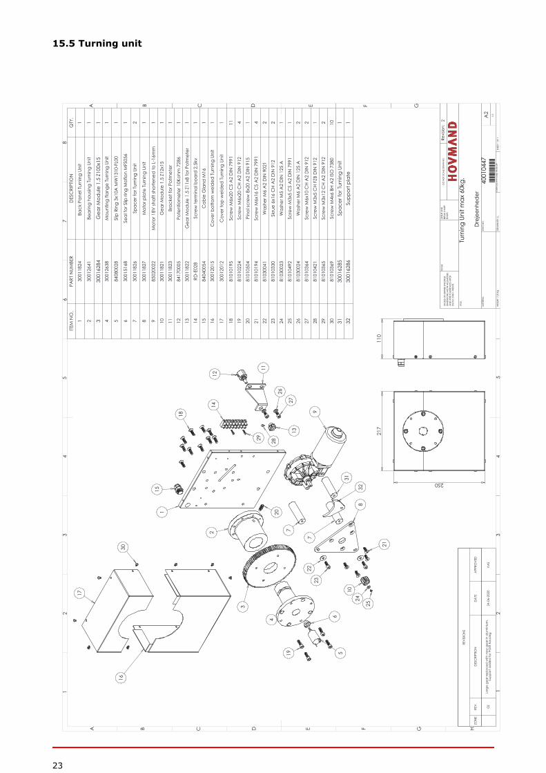
15.5 Turning unit
16
17
13
12
15
30
1
2
3
4
519
9
31
8
21
2223
1024
25
11
26
27
29
14
18
2028
6
7
7
32
217
250
110
ITEM
NO
.PA
RT N
UMBE
RD
ESC
RIPT
ION
QTY
.
130
0118
24Ba
ck P
anel
Tur
ning
Uni
t 1
230
0126
41Be
arin
g ho
usin
g Tu
rnin
g Un
it1
330
0162
84G
ear M
odul
e 1.
5 Z1
00x1
51
430
0126
38M
ount
ing
flang
e Tu
rnin
g Un
it1
584
0800
28Sl
ip R
ing
3x10
A M
W13
10-F
L00
1
630
0151
68Se
al fo
r Slip
ring
Mof
lon
MFS
056
1
730
0118
26Sp
acer
for T
urni
ng U
nit
2
830
0118
27M
otor
pla
te T
urni
ng U
nit
1
985
0200
22M
otor
18V
shaf
t sho
rtene
d to
L-1
6mm
1
1030
0118
21G
ear M
odul
e 1.
5 Z1
2x15
1
1130
0118
23Br
acke
t for
Pot
met
er1
1284
1700
05Po
tent
iom
eter
10K
ohm
728
61
1330
0118
22G
ear M
odul
e 1.
5 Z1
1x8
for P
otm
eter
1
14RD
-E02
8Sc
rew
term
inal
boa
rd 2
,5kv
1
1584
0400
54C
able
Gla
nd M
161
1630
0120
15C
over
bot
tom
wel
ded
Tur
ning
Uni
t1
1730
0120
12C
over
top
wel
ded
Tur
ning
Uni
t1
1881
0101
95Sc
rew
M6x
20 C
S A
2 D
IN 7
991
11
1981
0102
24Sc
rew
M6x
20 C
H A
2 D
IN 9
124
2081
0105
04Pi
nol s
crew
8x2
0 A
2 D
IN 9
151
2181
0101
94Sc
rew
M6x
16 C
S A
2 D
IN 7
991
4
2281
0300
41W
ashe
r M6
A2
DIN
902
12
2381
0103
30Sk
rue
6x16
CH
A2
DIN
912
2
2481
0300
23W
ashe
r M5
A2
DIN
125
A1
2581
0104
92Sc
rew
M3x
5 C
S A
2 D
IN 7
991
1
2681
0300
24W
ashe
r M6
A2
DIN
125
A2
2781
0103
64Sc
rew
M6x
10 C
H A
2 D
IN 9
122
2881
0104
21Sc
rew
M3x
5 C
H FZ
B D
IN 9
121
2981
0103
65Sc
rew
M3x
12 C
H A
2 D
IN 9
122
3081
0103
69Sc
rew
M4x
6 BH
A2
ISO
738
010
3130
0162
85Sp
acer
for T
urni
ng U
nit
132
3001
6286
Supp
ort p
late
1
REV
ISIO
NS
ZON
ERE
V.
DES
CRI
PTIO
ND
ATE
APP
ROV
ED
02La
rge
gear
repl
aced
with
new
gea
r in
alum
iniu
m.
Supp
ort a
dd
ed fo
r PO
M h
ousin
g24
-06-
2020
KAS
A B C D E F G H
12
34
56
78
A B C D E F G
12
34
5
A2
MA
TERI
AL:
Revi
sion:
2
Turn
ing
Unit
max
60k
g.
4001
0447
40010447
DRA
WN
BY:
LL
W
EIG
HT: 7
.20
KgSH
EET 1
OF
1
1:2
DW
G N
O.
TITLE
:
DO
NO
T SC
ALE
DRA
WIN
GD
EBUR
AN
D
BREA
K SH
ARP
ED
GES
FINIS
H:UN
LESS
OTH
ERW
ISE
SPEC
IFIE
D:
DIM
ENSI
ON
S A
RE IN
MILL
IMET
ERS
AN
D W
ITH T
OLE
REN
CES
AFT
ERD
S/IS
O 2
768-
1 M
IDD
EL
Dre
jeen
hede
r
18.0
6.29
D
ate[
yy.m
m.d
d]:

24
15.6 Tool
2 4
5
9
6
21
78
13
10
15
16
11
12
3
14
20
18 17
ITEM
NO
.PA
RT N
UMBE
RD
ESC
RIPT
ION
Def
ault/
QTY
.
130
0174
58Ba
ck fr
ame
Qui
ckC
lam
p 30
-60L
wel
ded
1
230
0010
09A
rm q
uick
Cla
mp
Kitc
hen
Lift
2
381
0600
15Bl
ind
rive
t 6,4
x14,
2 ss
clo
sed
64
4000
1001
Aks
el fo
r hæ
ngse
l Qui
ckC
lam
p2
540
0005
95A
ksel
for t
rykr
ulle
Ked
ellø
fter
2
681
1701
08Tr
ykru
lle ti
l ked
ellø
fter
2
730
0003
69Ho
lder
for a
ctua
tor c
lam
ping
func
tion
1
885
0204
40A
ctua
tor d
oubl
e-ac
ting.
2x5
0mm
. 400
0Nm
1
940
0018
52Tr
ykfo
d 1
, 80L
gry
de
210
8101
0284
Scre
w M
10x1
6 BH
A2
ISO
738
04
1181
0101
04Sc
rew
M6x
10 B
H A
2 IS
O 7
380
412
8101
0266
Scre
w M
6x16
BH
A2
ISO
738
04
1330
0016
51C
over
for a
ctua
tor Q
uick
Cla
mp
114
8101
0271
Scre
w M
6x40
BH
A2
ISO
738
04
1581
0101
75Bo
lt fo
r act
uato
r M10
x40
afko
rtet
216
8102
0050
Låse
møt
rik M
10 A
2 D
IN 9
852
1740
0006
71Br
acke
t for
act
uato
r2
1881
0101
93Sc
rew
M6x
12 C
S A
2 D
IN 7
991
419
4000
1053
Dup
sko
80x4
01
2081
0200
48Lo
ck n
ut M
6 A
2 D
IN 9
854
2181
0102
30Sc
rew
M6x
50 C
H A
2 D
IN 9
124
A B C D E F G H
12
34
56
78
A B C D E F G
12
34
5
A2
MA
TERI
AL:
Revi
sion:
3
Qui
ckC
lam
p 30
-60L 30
0174
5730017457
DRA
WN
BY:
LL
W
EIG
HT: 1
4.27
Kg
EP
SHEE
T 1 O
F 1
1:4
DW
G N
O.
TITLE
:
DO
NO
T SC
ALE
DRA
WIN
GD
EBUR
AN
D
BREA
K SH
ARP
ED
GES
FINIS
H:UN
LESS
OTH
ERW
ISE
SPEC
IFIE
D:
DIM
ENSI
ON
S A
RE IN
MILL
IMET
ERS
AN
D W
ITH T
OLE
REN
CES
AFT
ERD
S/IS
O 2
768-
1 M
IDD
EL
Kitc
hen
21.0
5.11
D
ate[
yy.m
m.d
d]:
25
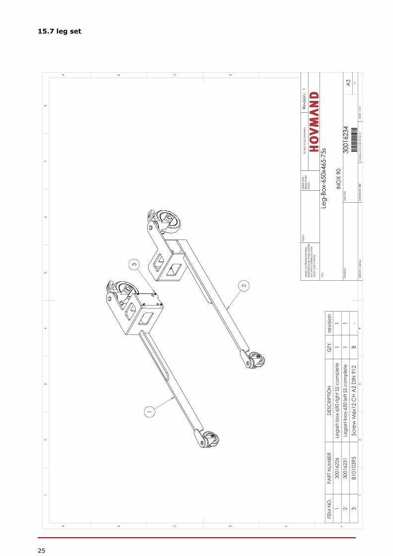
15.7 leg set
1
2
3
ITEM
NO
.PA
RT N
UMBE
RD
ESC
RIPT
ION
QTY
.re
visio
n1
3001
6226
Legs
et-b
ox-6
50 ri
ght S
S co
mpl
ete
11
230
0162
31Le
gset
-box
-650
left
SS c
ompl
ete
11
381
0103
95Sc
rew
M6x
12 C
H A
2 D
IN 9
128
-
D E FC
12
34
BA
32
15
C D
46
78
A B
Dat
e[yy
.mm
.dd
]:20
.06.
10
INO
X 90
UNLE
SS O
THER
WIS
E SP
ECIF
IED
:D
IMEN
SIO
NS
ARE
IN M
ILLIM
ETER
SA
ND
WITH
TO
LERE
NC
ES A
FTER
DS/
ISO
276
8-1
MID
DEL
FINIS
H:D
EBUR
AN
D
BREA
K SH
ARP
ED
GES
DO
NO
T SC
ALE
DRA
WIN
G
TITLE
:
DW
G N
O.
1:5
SHEE
T 1 O
F 1
WEI
GHT
: 12.
88 K
gD
RAW
N B
Y: R
BK
3001
6234
30016234
Leg-
Box-
650x
465-
75s
Revi
sion:
1
MA
TERI
AL:
A3
26
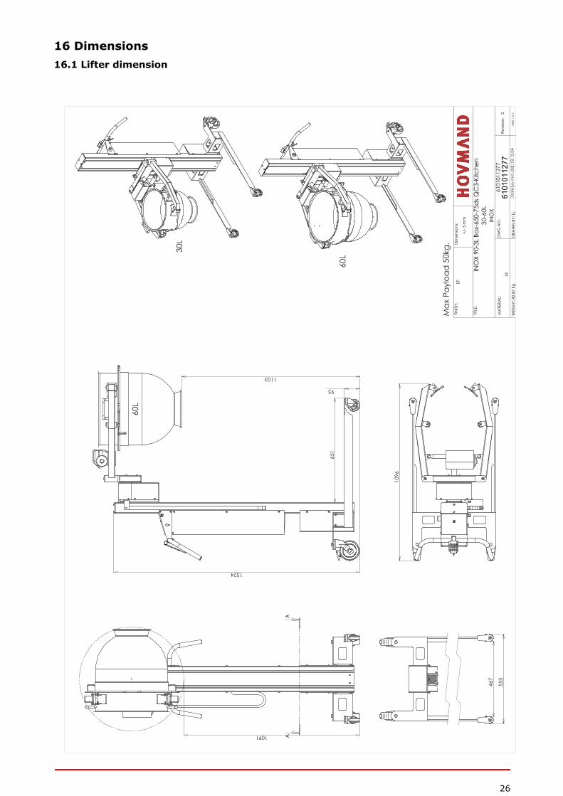
16 Dimensions16.1 Lifter dimension
651
95
1524
1103
109
6
1091
AA
30L
60L
467
553
Max
Pay
load
50k
g.
60L
MA
TERI
AL:
Revi
sion:
2
INO
X 90
-3L
Box-
650-
75ds
QC
3-Ki
tche
n
6101
0112
776101011277
DRA
WN
BY:
LL
W
EIG
HT: 8
2.87
KgEP
SHEE
T 1
OF
3
DW
G N
O.
TITLE
:
FINIS
H:
INO
X30
-60L
Dat
e[yy
.mm
.dd
]:SS
Dim
ensio
ns:
+/- 5
mm
18.1
2.04
27
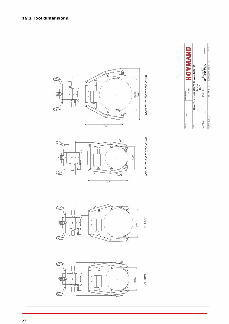
16.2 Tool dimensions
35
3
500
44
4
607
35
0
579
784
Min
imum
dia
met
er Ø
350
Max
imum
dia
met
er Ø
500
60 L
iter
30 L
iter
MA
TERI
AL:
Revi
sion:
2
INO
X 90
-3L
Box-
650-
75ds
QC
3-Ki
tche
n
6101
0112
776101011277
DRA
WN
BY:
LL
W
EIG
HT: 8
2.87
KgEP
SHEE
T 3
OF
3
DW
G N
O.
TITLE
:
FINIS
H:
INO
X30
-60L
Dat
e[yy
.mm
.dd
]:
SS
Dim
ensio
ns:
+/- 5
mm
18.1
2.04

28
17 Annual inspection
Date of inspection: Controller: Comments:
____________________ ____________________ _________________________________
____________________ ____________________ _________________________________
____________________ ____________________ _________________________________
____________________ ____________________ _________________________________
____________________ ____________________ _________________________________
____________________ ____________________ _________________________________
____________________ ____________________ _________________________________
____________________ ____________________ _________________________________
____________________ ____________________ _________________________________

29

30

31

CONTACT HOVMAND FOR SUPPORT AND SERVICE:
+45 57 83 33 [email protected]
Hovmand A/S | Sandvadsvej 15 | DK-4600 Køge+45 57 83 33 00 | [email protected] | www.hovmand.com