Flex Network High-Speed Counter Unit User Manual - HMI Store
77
Flex Network High Speed Counter Unit User Manual Digital Electronics Corporation
-
Upload
khangminh22 -
Category
Documents
-
view
0 -
download
0
Transcript of Flex Network High-Speed Counter Unit User Manual - HMI Store

Flex NetworkHigh Speed Counter
Unit User Manual
Digital Electronics Corporation

1Flex Network High-Speed Counter Unit User Manual
PrefaceThank you for purchasing the Pro-face’s Flex Network High-Speed Counter unit,hereafter referred to as “FN-HC unit” or “unit”.The unit is designed to be used with Pro-face’s Graphical Logic Controller (GLC)Series, LT Series, and GP3000 Series FLEX NETWORK board type (hereafterreferred to as “GLC”) as a remote I/O system.This manual explains the overall features and specifications of the unit, as well as itsinstallation procedures.Please be sure to read this manual thoroughly to understand the correct and safe usageof this product and its features.
< Note >1. It is forbidden to copy the contents of this manual, in whole or in part,
except for the user's personal use, without the express permission of theDigital Electronics Corporation.
2. The information provided in this manual is subject to change without notice.3. This manual has been written with care and attention to detail; however, should
you find any errors or omissions, please contact the Digital Electronics Corpo-ration and inform us of your findings.
4. Please be aware that Digital Electronics Corporation shall not be held liable bythe user for any damages, losses, or third party claims arising from the uses ofthis product.
All Company/Manufacturer names used in this manual are the registered trademarks ofthose companies.© 2001, Digital Electronics CorporationFLEX NETWORK® is a registered trademark of Digital Electronics Corporation.

Preface
2 Flex Network High-Speed Counter Unit User Manual
Table of ContentsPreface ........................................................................................................................ 1Essential Safety Precautions ................................................................................... 5General Precautions ................................................................................................. 7Flex Network Unit Models ....................................................................................... 7Compatible GLC Units ............................................................................................. 7Package Contents ..................................................................................................... 7Driver ......................................................................................................................... 8UL/c-UL (CSA) Application Notes .......................................................................... 8CE Marking Notes .................................................................................................... 8Documentation Conventions .................................................................................... 9
CHAPTER 1 INTRODUCTION
1.1 System Design ..................................................................................... 1-11.2 Accessories .......................................................................................... 1-3
CHAPTER 2 SPECIFICATIONS
2.1 General Specifications ........................................................................ 2-12.1.1 Electrical ................................................................................2-12.1.2 Environmental ........................................................................2-12.1.3 Structural ...............................................................................2-3
2.2 Performance Specifications ................................................................ 2-32.2.1 Performance Specifications ...................................................2-22.2.2 Data Transfer Settings (Flex Network Specifications) ..........2-32.2.3 Input / Output Specifications .................................................2-5
2.3 Input / Output Circuit .......................................................................... 2-52.4 Part Names and Features ................................................................... 2-7
2.4.1 Flex Network High-Speed Counter Unit ..............................2-72.5 Dimensions ......................................................................................... 2-10
2.5.1 Flex Network High-Speed Counter Unit ............................2-10
CHAPTER 3 INSTALLATION AND WIRING
3.1 Installation ........................................................................................... 3-13.1.1 Flex Network High-Speed Counter Unit Installation / Removal 3-1
3.2 Wiring ................................................................................................... 3-33.2.1 Connecting the Flex Network Communication Cable ...........3-33.2.2 Connecting the Power Cord..................................................3-43.2.3 General Cautions ...................................................................3-5

Preface
3Flex Network High-Speed Counter Unit User Manual
CHAPTER 4 FUNCTIONAL SPECIFICATIONS
4.1 Operation Mode .................................................................................. 4-14.2 Functions .............................................................................................. 4-2
CHAPTER 5 DATA SETTINGS
5.1 Flex Network Driver Settings ............................................................ 5-15.2 Data Settings ....................................................................................... 5-6
CHAPTER 6 PROBLEMS AND SOLUTIONS
6.1 Prior to Troubleshooting ..................................................................... 6-16.2 Error Code Display ............................................................................. 6-26.3 Troubleshooting for GLC2000/LT Series ......................................... 6-3
6.3.1 Troubleshooting Checklist for GLC2000/LT Series ..............6-36.3.2 Error Code List for GLC2000/LT Series ..............................6-7
6.4 Troubleshooting for GP3000 Series .................................................. 6-86.4.1 Troubleshooting Checklist for GP3000 Series ......................6-86.4.2 Error Code List for GP3000 Series ....................................6-12
APPENDIX
A.1 Ring Counter Function - Program Example .................................... A-1A.2 Comparator Output Function - Program Example .......................... A-4A.3 Cam Switch Output Function - Program Example .......................... A-7

Preface
4 Flex Network High-Speed Counter Unit User Manual
• An emergency stop circuit and an interlock circuit shouldbe constructed outside of this unit. Constructing thesecircuits inside a system that uses this unit may cause arunaway situation, system failure, or an accident due tounit failure.
• Systems using this unit should be designed so that out-put signals which could cause a serious accident aremonitored from outside the unit.
• This product is not appropriate for use with aircraft con-trol devices, medical life-support equipment, central trunkdata transmission (communication) devices, or nuclearpower control devices, due to their inherent requirementsof extremely high levels of safety and reliability.
• When using this product with transportation vehicles(trains, cars, and ships), disaster and crime-preventiondevices, various types of safety equipment, and medicaldevices that are not life-support related, use redundantand/or failsafe system designs to ensure proper reliabil-ity and safety.
This guide contains a variety of safety markings for safe and correct operation ofthe FN-HC unit. Please read this installation guide and any related manuals care-fully to fully understand how to correctly use the FN-HC unit’s functions.
Safety SymbolsPlease pay attention to these symbols and follow all instructions given.The safety symbols and their meanings are as follows:
Indicates situations where severe bodilyinjury, death or major machine damagewill definitely occur.Indicates situations where severe bodilyinjury, death or major machine damagecan possibly occur.
Indicates situations where slight bodilyinjury or machine damage can occur.
DANGER
WARNING
CAUTION
Essential Safety Precautions
DANGERS

Preface
5Flex Network High-Speed Counter Unit User Manual
• Communication cables or I/O signal lines must be wiredseparately from the main circuit (high-voltage, large-cur-rent) line, high-frequency lines such as inverter and powerlines. Otherwise, a malfunction may occur due to noise.
• This unit must be installed according to directions givenin its Installation Guide and User manual. Improper instal-lation may cause the unit to malfunction or fail.
• This unit must be wired according to directions in the In-stallation Guide and User Manual. Improper wiring maycause a malfunction, failure or electric shock.
• Do not allow foreign substances, including chips, wirepieces, water, or liquids to enter inside this unit’s case.Otherwise, a malfunction, failure, electric shock, or firemay occur.
• When disposing of this unit, it should be processed ac-cording to your country’s industrial waste disposal laws.
• Prior to installing, removing, wiring, and conducting main-tenance or inspections, be sure to disconnect power tothis unit to prevent an electric shock or fire.
• Do not disassemble or remodel this unit, since it may leadto an electric shock or fire.
• Do not use this unit in an environment that contains flam-mable gases since an explosion may occur.
• Do not use this unit in an environment that is not speci-fied in either the Installation Guide or User Manual. Other-wise, an electric shock, fire, malfunction or other failuremay occur.
• Due to the possibility of an electric shock or malfunction, donot touch the unit’s power terminals while it is operating.
WARNINGS
CAUTIONS

Preface
6 Flex Network High-Speed Counter Unit User Manual
Flex Network units allow the GLC to communicate via a Flex Network system. TheFlex Network unit model numbers are listed as follows:
To Prevent Unit Damage• Avoid storing or operating this unit in either direct sunlight or excessively dusty
or dirty environments.• Because this unit is a precision instrument, do not store or use it in locations
where excessive shocks or vibration may occur.• Avoid covering this unit’s ventilation holes, or operating it in an environment
that may cause it to overheat.• Avoid operating this unit in locations where sudden temperature changes can
cause condensation to form inside the unit.• Do not use paint thinner or organic solvents to clean this unit.
General Precautions
Flex Network Unit Models
Product Family Unit Name Model No. NodesRequired Manual
FN-X16TS41 1FN-X32TS41 2FN-Y16SK41 1FN-Y16SC41 1FN-XY08TS41 1FN-XY16SK41 1FN-XY16SC41 1FN-XY32SKS41 4FN-Y08RL41 1FN-AD02AH41 1FN-DA02AH41 1FN-AD04AH11 4FN-DA04AH11 4FN-PC10SK41 4FN-PC10LD41 -
High-Speed Counter Unit FN-HC10SK41 8 This Manual
Flex Network
I/O Unit DIO Unit User Manual
Analog Unit
Single-Axis Positioning Unit Single-Axis Positioning UnitUser Manual
Analog Unit User Manual
2-Channel Analog UnitUser Manual

Preface
7Flex Network High-Speed Counter Unit User Manual
Compatible GLC Units
Package ContentsFlex Network High-SpeedCounter Unit (1)(FN-HC10SK41)
Flex Network High-SpeedCounter Unit InstallationGuide – English/Japanese (1)
The Flex Network High-SpeedCounter Unit User Manual issold separately.
Special care and attention have been given to the packaging of this unit. However,if any of the items are damaged or missing, please contact your local distributorimmediately for prompt service.
Installation
The following GLC units can be used with the Flex Network units. (GLC, LT , and GPare referred to collectively as the “GLC” in this manual.)ProductFamily Unit Name Model No.
GLC2300T GLC2300-TC41-24VGLC2300L GLC2300-LG41-24V
GLC2400 Series GLC2400T GLC2400-TC41-24VGLC2500-TC41-24VGLC2500-TC41-200VGLC2600-TC41-24VGLC2600-TC41-200V
LT TypeB GLC150-BG41-FLEX-24VLT Type B+ GLC150-BG41-XY32KF-24V
LTC Type B+ GLC150-SC41-XY32KF-24VLT Type C GLC150-BG41-RSFL-24VAGP-3300L AGP3300-L1-D24-FN1MAGP-3300T AGP3300-T1-D24-FN1M
GP-3400 Series AGP-3400T AGP3400-T1-D24-FN1MAGP3500-T1-D24-FN1MAGP3500-T1-AF-FN1MAGP3600-T1-D24-FN1MAGP3600-T1-AF-FN1M
GP GP3000 Series GP-3500 Series AGP-3500T
GP-3600 Series AGP-3600T
GP-3300 Series
GLC2500T
GLC2600 Series GLC2600T
LT LT Series
Series Name
GLC GLC2000 Series GLC2500 Series
GLC2300 Series

Preface
8 Flex Network High-Speed Counter Unit User Manual
DriverThe driver for the Flex Network Unit is required in order to use the unit.
For GLC2000 series and LT series,You can select the Flex Network Driver via GP-PRO/PBIII C-Package (Pro-ControlEditor) or LT Editor.If the selection of the appropriate unit's name does not appear in the [I/O Configuration]- [I/O Unit Settings] area, you will need to update the driver file.You can download the latest driver from Pro-face's web site.URL :http://www.pro-face.com/
For GP3000 Series,You can select the Flex Network Driver via GP-Pro EX as an I/O driver.
UL/c-UL (CSA) Application NotesThe FN-HC10SK41 is a UL/c-UL (CSA) listed product. (UL file No. E220851)This unit conforms to the following standards:
UL 508 Industrial Control Equipment CAN/CSA C22.2 No.1010-1 MEASUREMENT AND CONTROL EQUIPMENT(Safety requirements for electrical equipment for measurement and laboratory use)
FN-HC10SK41 (UL Registration Model: 2980051-01)<Cautions>• The FN-HC must be a built-in component of an end-use product.• If the FN-HC is mounted so as to cool itself naturally, be sure to install the unit in a
vertical (upright) panel, using either a DIN rail, or the installation screw holes.• The power unit attached to the FN-HC should be a UL/c-UL (CSA) approved
Class 2 power unit, or a Class 2 transformer. *1
If a single power supply is used to power the GLC, or multiple Flex Network units,design the wiring so the sum of the Flex Network unit’s consumption current and thetotal load current does not exceed the Class 2 power unit or the Class 2 transformer’srating.
CE Marking NotesThe FN-HC10SK41 is a CE marked product that conform to EMC directivesEN55011 class A and EN61000-6-2. For detailed CE Marking information, pleasecontact your Flex Network distributor.
*1 A Class 2 power supply unit or Class 2 power supply transformer is defined byNEC as being 30V and, at 8A or less output, at less than 100VA.

Preface
9Flex Network High-Speed Counter Unit User Manual
Symbol Meaning
Indicates important information or procedures that must be followed forcorrect and risk-free software/device operation.
Provides useful or important supplemental information.
*1 Provides useful or important supplemental information.Cross-references useful or important supplemental information.
GLCGeneric name for the "GLC Series" of Graphic Logic Controllers made byPro-face. In this manual, it also indicates "LT Series" and "GP3000 SeriesFLEX NETWORK board type".
Documentation ConventionsThe list below describes the documentation conventions used in this manual.

10 Flex Network High-Speed Counter Unit User Manual
Memo

1–1Flex Network High-Speed Counter Unit User Manual
When connecting to the Flex Network, two channels are available – CH1 and CH2.Each channel outputs the same data and either can be used for data transmission.No software setup is required.The maximum number of connectable nodes when using a single channel is 31, andwhen using a second channel, the number increases by 32 to a total of 63.
• When conecting the FN-HC to the Flex Network, each unit connectedwill use 128 bits of GLC memory, equivalent to 8 I/O nodes. The maxi-mum number of connectable nodes (see above) therefore differsfrom the maximum number of connectable units.
• The Flex Network uses high-speed data-transfer technology, and ifa cable used for data transfer is not the same as that specified in thisdocument, network data-transfer performance cannot be guaranteed.Thus, be sure to use only the cable(s) recommended.
Flex Network I/F
Flex Network Units
Maximum cable length: 200m (6Mbps) 100m (12Mbps)Maximum No. of nodes: 31
With One (1) Channel
1.1 System Design
Chapter1 Introduction
1. System Design2. Accessories
This high-speed counter unit can be connected to a Flex Network.There are three types of counting operations. Select the type of counting that fits your
application needs. See 4.2 Functions• DC input/16-bit up counter (at 10kpps/1 multiplication)• DC input/32-bit up counter (at 10kpps/1 multiplication)• Differential input/32-bit up/down counter (at 200kpps/1 multiplication) and DC input
(at 3kpps/1 multiplication)
GLC

1–2 Flex Network High-Speed Counter Unit User Manual
Chapter 1 – Installation
16-point InputFN-HC Unit
DC24V DC24V
8-point Input /8-point Output
FN-HC Unit
Valve/Actuator
Lamp
DC24V DC24V
to next unit *1
Flex Network Unit
Flex Network I/F
6Mbps is the recommended speed.
With Two (2) Channels
Maximum cable length: 400m (6Mbps), 200m (12Mbps)Maximum No. of nodes: 63 (31 + 32)
Standard System Design
to next unit *1
*1.Be sure the Terminal Switch (TERM) at each end of the network’s last unit is ON.
SensorOperationSwitch
SensorOperation
Switch
Pulse Signal
When using two channels, up to 32 nodes can be connectedto either channel.
Pulse Signal
Channel 2
Channel 1
Channel 2
Channel 1
GLC
GLC

1–3Flex Network High-Speed Counter Unit User Manual
Chapter 1 – Installation
1.2 AccessoriesAll optional equipment listed here is sold separately.
Optional Items
Item Model No. DescriptionFN-CABLE 2010-31-MS(10m)FN-CABLE 2050-31-MS(50m)FN-CABLE 2200-31-MS(200m)
Flex NetworkCommunication Cable Connect GLC units with Flex Network units.

1–4 Flex Network High-Speed Counter Unit User Manual
Memo

2–1Flex Network High-Speed User Manual
2.1 General Specifications
Chapter2 Specifications
1. General Specifications2. Functional Specifications3. I/O Circuit Connection
Drawings4. Part Names and Features5. Dimensions
2.1.1 Electrical
2.1.2 Environmental
AmbientOperatingTemperature
0oC to 55oC
Storage Temp. -25oC to +70oCAmbient Humidity 30%RH to 95%RH (no condensation) Level RH-1Storage Humidity 30%RH to 95%RH (no condensation) Level RH-1Air Purity (Dust) 0.1mg/m3 or less (non-conductive levels)Corrosive Gasses Free of corrosive gassesAtmosphericPressure 800 hPa to 1114 hPa (2,000 meters or lower)
VibrationResistance
IEC61131-2 (JIS B 3501) compliantWhen vibration IS NOT continuous:10Hz to 57Hz 0.075mm, 57Hz to 150 Hz 9.8m/s2
When vibration IS continuous:10Hz to 57Hz 0.035mm, 57Hz to 150 Hz 4.9m/s2
X,Y, Z directions for 10 times (80 min.)
Shock EnduranceIEC61131-2 (JIS B 3501) compliant147m/s2 (for 11ms in X,Y, Z directions - 2 times each)
Noise Immunity(via noisesimulator)
Noise Voltage: 1000Vp-pPulse Duration: 1µsArise Time: 1ns
ElectrostaticDischargeImmunity
Contact discharge of 6kV (IEC61000-4-2, Level 3)
Rated Voltage DC24VRated VoltageRange DC20.4V to DC28.8V
AllowableVoltage Drop 10 ms or less (Power Voltage DC24V)
PowerConsumption 2.5W or less
In-rush Current 15A or lessVoltageEndurance AC500V 20mA for 1 min. (between I/O and earth terminals)
InsulationResistance DC500V at 10M Ω or higher (between I/O and earth terminals)

Chapter 2 – Specifications
2–2 Flex Network High-Speed User Manual
1. Refer to page 4–4 for the measurement speed of each counter .
ProtectionProtection: Equivalent to IP20Installation method: 35mm [1.38 in.] DIN railing or screw installation
Cooling Method Natural air c irculationWeight 150g or lessExternalDimensions W 108mm [4.25 in.] x H 45mm [1.77 in.] x D 49mm [1.93 in.]
2.1.3 Structural
2.2 Performance Specifications2.2.1 Performance Specifications
CounterType Input Type
Pulse CountMethod
(up/downcounter)
CalculatedSpeed
No. ofCounters
CalculationRange
CompareOutputMode
16-bit upcounter
10kpps /1kpps
20 to FFFF0 to 65535(16 bits)
ComparatorOutput x2
(=)
32-bit upcounter
10kpps /1kpps
10 to FFFFFFFF
0 to 4,294,967,295(32 bits)
ComparatorOutput x 2
(=)1-phase
1-multiplication /2-phase
1-multiplication*1
200kpps /50kpps
2-phase2-multiplication*1
100kpps /25kpps
2-phase4-multiplication*1
50kpps /12.5kpps
1-phase1-multiplication /
2-phase1-multiplication*1
3kpps /1kpps
2-phase2-multiplication*1
1.5kpps /0.5kpps
2-phase4-multiplication*1
0.75kpps/0.25kpps
DC Input(DC24VOpen
Collector)
Differ-ential Input
(Line Driver)
DC Input(DC24VOpen
Collector)
32-bit up/down
counter 80000000h to7FFFFFFFh(32-bit signed
binary)-2,147,483,648
to+2,147,483,647
Cam SwitchSimultaneous
Outputx 2
1(Encoder A,
Bdifferential
input)
80000000h to7FFFFFFFh(32-bit signed
binary)-2,147,483,648
to+2,147,483,647
Cam SwitchSimultaneous
Outputx 2
1(DC input)

Chapter 2 – Specifications
2–3Flex Network High-Speed User Manual
2.2.2 Data Transfer Settings (Flex Network Specifications)
GLC2000/LT Series GP3000 SeriesCommunicationConfigurationConnectionMethodMaximumDistanceCommunicationMethodCommunicationSpeedCommunicationInterfaceError Check
Number ofConnectableNodes
63 (max.), 1008 I/O points(depending on type of units used.)
63 stations max.,Bit variable input: 256 points,Bit variable output: 256 points,Integer variable input: 64 points,Integer variable output: 64 points(depending on type of units used.)
Number ofOccupied Nodes
6Mbps, 12Mbps
Differential, pulse-transformer isolation
Format detection, bit detection, CRC-12 detection
8
1:N
Multi-Drop Connection200m/channel at 6 Mbps100m/channel at 12 MbpsCyclic T ime Division, half-duplex

Chapter 2 – Specifications
2–4 Flex Network High-Speed User Manual
Pulse Input (PLS 1/2) External Reset Input(RST 1/2)
DC5V
DC4.5V to DC5.5V
Level
Phase
470ΩDC19V or higherDC5V or lower
OFF-ON Maximum: 1.5msON-OFF Maximum: 1.5ms
OFF-ONON-OFF
Short-circuitProtection None
50mA or lowerOutputDelay
Maximum: 1msMaximum: 1ms
Rated OutputVoltage DC24V
Rated OutputVoltage Range DC24V (+/-10%)
Output VoltageDrop DC1.5V or lower
Output Current
Leakage Current 0.1mA or lower
4.9kΩInput ON VoltageInput OFF VoltageInputDelay
DC Input (DC24V Open collector)
Rated InputVoltage DC24V
Max. Input Voltage DC26.4 V
Calculated Speed(Rise and Fall time)
EIA Standard RS-422-ADifferential Driver(Equivalent to TexasInstruments SN75157)
Input Type Differential Input (line driver)
Min. Pulse Width
Input Impedence
InputSignal
Square wave 0/24V signal90o phase differential 2-phase signal, 1 phase + directional signal,1 phase addition signal
INPUT
OUTPUT
2.2.3 Input / Output Specifications
t tt = 0.5µs or less
(200kpps)
t tt = 10µs or less
(10kpps)5µs
2.5µs 2.5µs
2.5ms100µs
50µs50µs

Chapter 2 – Specifications
2–5Flex Network High-Speed User Manual
1. The FN-HC unit’s input line is not isolated. When connecting this unit to a linedriver that is not isolated, be sure to connect the signal ground (SG) terminal.
2. Line Driver
3. Open Collector (Sink Output) Open Collector (Source Output)
4. The Input Common (I-COM) shown here is connected to a Sink Output type. (Thedotted line shows the connection with a Source Output type.)
PLSn
I-COMDC24V DC24V
PLSn
I-COM
This section explains the I/O connection (see circuit diagram, below) for the FN-HC unit.
If the FN-HC unit’s power lines and output lines, and the sen-sor power lines seem to be receiving excessive levels of fieldnoise, be sure to separate the power and signal lines.
FN-HC Unit Connection Diagram (from Rotary Encoder)
DC24V
FN-HC Unit
L
OV
24VOUT1
OUT2
A+
B+
B-
PLS1/A Phase
RST1RST2
I-COM*3
RotaryEncoder
(LineDriver) *3
O-COM
RotaryEncoder
(OpenCollector)*2
L
A-
DC24V
SG*1
2.3 Input / Output Circuit
PLS2/B Phase
A Phase/B Phase (+)
GND (SG terminal)A Phase/B Phase (-)

Chapter 2 – Specifications
2–6 Flex Network High-Speed User Manual
Input/Output Signal
Terminal Name FeatureT R+ Flex Network CommunicationT R- Flex Network Communication+24V Unit Power (DC24V)OV Unit Power (DC0V)
OUT 1Comparator Output (Counter 1) /Cam Switch 1 Output
OUT 2Comparator Output (Counter 2) /Cam Switch 2 Output
O-COM Output Common+A A Phase Line Driver DC5V Differential Input +-A A Phase Line Driver DC5V Differential Input -+B B Phase Line Driver DC5V Differential Input +-B B Phase Line Driver DC5V Differential Input -SG Signal GroundPLS1 Counter 1 DC InputPLS2 Counter 2 DC Input*1RST 1 External Reset Signal (Counter 1)RST 2 External Reset Signal (Counter 2) *1
I-COMInput Common DC24V(with Source Output type connection: 0V)
CommunicationChannel
Power
DC24V Input
Control Output(DC24V OpenCollector Output)
Differential LineDriver Input
1. PLS2 and RST2 Input are available only with Input Mode 1 (Mode 1).

Chapter 2 – Specifications
2–7Flex Network High-Speed User Manual
A:Dip SwitchesDesignates, from left to right, the Output Holdsetting, Communication Speed setting, and first(hex) digit of the FN-HC unit’s S-No.
Factory SettingsCommunication Speed: 6 MbpsStation Number (S-No): 0Output Hold: Non-Hold
B: Station No. SwitchDesignates the second (hex) digit of the FN-HCunit’s S-No.
C:TerminatorTurns the termination resistance feature ON or OFF.
D:Status LEDIndicates the following conditions.
A B
C
D
E
P W R G reen Pow er O N w hen pow er is tu rned O N .
ERR R ed ErrorO N w hen c om m unic a tion e rro r oc c urs;O F F w hen c om m unic a tion is norm al.
OUT1 G reenC am Sw itc h 1 /C ounter 1C om para tor O utput
O N w hen C am Sw itc h 1 O u tput is O N ;O N w hen C ounter 1 C om para tor ou tpu ts.
OUT2 G reenC am Sw itc h 2 /C ounter 2C om para tor O utput
O N w hen C am Sw itc h 2 O u tput is O N ;O N w hen C ounter 2 C om para tor ou tpu ts.
CW /CCW G reen R ota ting D irec tionO N during C W (fo rw ard ro ta tion);O F F during C C W (reverse ro ta tion).
RS T1 O rangeExterna l R eset 1(C ounte r 1 )
O N w hen R eset 1 input is O N .
RS T2 O rangeExterna l R eset 2(C ounte r 2 )
O F F w hen R eset 2 input is O N .
2.4 Part Names and Features2.4.1 Flex Network High-Speed Counter Unit
E: DIN Rail Attachment HookUse to attach the FN-HC Unit to the DIN rail.
Chapter 2 – Specifications
2–8 Flex Network High-Speed User Manual
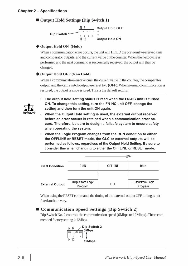
Output Hold ON (Hold)When a communication error occurs, the unit will HOLD the previously-received camand comparator outputs, and the current value of the counter. When the next cycle isperformed and the next command is successfully received, the output will then bechanged.
Dip Switch 1
Output Hold OFF
Output Hold ON
Output Hold Settings (Dip Switch 1)
Output Hold OFF (Non Hold)When a communication error occurs, the current value in the counter, the comparatoroutput, and the cam switch output are reset to 0 (OFF). When normal communication isrestored, the output is also restored. This is the default setting.
• The output hold setting status is read when the FN-HC unit is turnedON. To change this setting, turn the FN-HC unit OFF, change thesetting and then turn the unit ON again.
• When the Output Hold setting is used, the external output receivedbefore an error occurs is retained when a communication error oc-curs. Therefore, be sure to design a failsafe system to ensure safetywhen operating the system.
• When the Logic Program changes from the RUN condition to eitherthe OFFLINE or RESET mode, the GLC or external outputs will beperformed as follows, regardless of the Output Hold Setting. Be sure toconsider this when changing to either the OFFLINE or RESET mode.
When using the RESET command, the timing of the external output OFF timing is notfixed and can vary.
GLC Condition RUN OFFLINE RUN
External OutputOutput from Logic
Program OFF Output from Logic Program
Dip Switch 2
12Mbps
Communication Speed Settings (Dip Swtich 2)Dip Switch No. 2 controls the communication speed (6Mbps or 12Mbps). The recom-mended factory setting is 6Mbps.
6Mbps

Chapter 2 – Specifications
2–9Flex Network High-Speed User Manual
Termination SettingsThis setting helps prevent reflections (echoes) from the terminating unit (adjusts thetermination impedance).Be sure that this termination setting for each channel in your system’s final unit is setto ON.
ONOFF
The Communication Speed setting status is read when the FN-HC unit isturned ON. To change this setting, turn the FN-HC unit OFF, change thesetting and then turn the unit ON again.
S-No. (Station No.) S-No. (Station No.)SW3 SW4 SwitchOFF OFF 1
OFF ON 0
ON ON F
S-No. 63 (3Fh)
Dip Switch
S-No. 1 (01h)
S-No. 16 (10h)
S-No. Setting Example
Dip Switch 3 Dip Switch 4
ON
OFF
The arrow’s tipindicates theposition
S-No. (Station Number) Setting (Dip Switches 3, 4)Station numbers from 1 to 63 are set in hexadecimal (01h to 3Fh). The factory setting is 0.The hex upper digit is controlled by the ON/OFF settings of Dip switch 3 and 4, andthe lower digit is set via the S-No. 0 to F setting.
The S-No. setting status is read when the FN-HC unit is turned ON. Tochange this setting, turn the FN-HC unit OFF, change the setting and thenturn the unit ON again.

Chapter 2 – Specifications
2–10 Flex Network High-Speed User Manual
2.5 Dimensions2.5.1 Flex Network High-Speed Counter Unit
Units: mm [in.]
108 [4.25]33
[1.3
0]45
[1.7
7]
15.1
[0.5
9]28
.2 [1
.11] 49
[1.9
3]3.5 [0.14]
3.9
[0.1
5]
12.1 [0.48]
The Termination Resistance setting status is read when the FN-HC unit isturned ON. To change this setting, turn the FN-HC unit OFF, change thesetting and then turn the unit ON again.

3–1Flex Network High-Speed Counter Unit User Manual
AttachmentPlace the unit’s curved, top lip over the topof the DIN rail, and then tilt the unit downuntil the bottom face attachment clip clicksinto place.
3.1 Installation
Chapter3 Installation and Wiring
1. Installation2. Wiring
3.1.1 FlexNetwork High-Speed Counter Unit Installation / Removal
DINRail
High-SpeedCounter Unit
StandardScrewdriver
RemovalUse a standard screwdriver to force the unit’sattachment clip down until the bottom of theunit is freed from the rail. Next, tilt the unit upand remove.
Down
Attaching the Unit to a 35 mm DIN Rail
Check that the FN-HC unit is installed horizontally. If it is not correctlyinstalled, it may overheat and cause a malfunction.
Prior to installing the FN-HC Unit, be sure that the mainpower supply is turned completely OFF.
WARNING

3–2 Flex Network High-Speed Counter Unit User Manual
Chapter 3 – Installation and Wiring
When Installing the Unit in a PanelDrill installation holes in the panel according to the dimensions given below and use M4screws to attach the unit. A torque of only 1.0 to 1.3N•m is sufficient.
I/O unit centerI/O unit outline
DIN railcenter
2φφφφφ4.5 [0.08φφφφφ0.18]35
.0 [1
.38]
50.3 [1.98]
98.4 to 100.6 [3.87 to 3.96]
48.1 to 50.3 [1.89 to 1.98]
16.1
[0.6
3]18
.9[0
.74]
98.4 to 100.6 [3.87 to 3.96]
48.1 to 50.3[1.89 to 1.98] 50.3 [1.98]
35.0[1.38]
16.1[0.63]18.9[0.74]
Unit: mm [in.]
Check that the FN-HC unit is installed horizontally. If it is not correctlyinstalled, it may overheat and cause a malfunction.

3–3Flex Network High-Speed Counter Unit User Manual
Chapter 3 – Installation and Wiring
Use jumper wiring between the distributed Flex Network units (T-type connections arenot possible).Pro-face recommends that the following cables be used:
Blue (TR+)
Shield (SLD)
White (TR-)
6.0 or less[0.24]
φ φ φ φ φ 3.2 or more [0.13]
5.2 or more [0.20]3.8 or less [0.15]
Crimp terminals should be either taped or covered with a plastic tube.
• The required torque for securing ring terminals is 0.6 to1.0 N•m.
• Up to 2 terminals can be connected.
3.2 Wiring
3.2.1 Connecting the Flex Network Communication Cable
The cable should be made as shown below:
The shield line should either be taped or covered with a plastic tube.Also, since the FN-HC unit has no shield (SLD) line, be sure to connectthis line to an insulated or closed terminal connector.
Use the following type of crimp terminals.Unit: mm [in.]
Manufacturer Model No. LengthFN-CABLE2010-31-MS 10mFN-CABLE2050-31-MS 50mFN-CABLE2200-31-MS 200m
Digital Electronics Corporation
To prevent an electric shock, prior to wiring the FN-HC unit,be sure that the main power supply is turned OFF.
WARNING
3–4 Flex Network High-Speed Counter Unit User Manual
Chapter 3 – Installation and Wiring
• Be sure that the main power supply is turned com-pletely OFF before wiring the unit’s power cord.
• The FN-HC unit uses only DC24V power. Using ei-ther the incorrect voltage or AC power could resultin damage to both the power supply and the unit.
• Since this unit has no ON/OFF switch, be sure to in-stall a breaker device to switch the power ON or OFF.
FN-X16TS41(S-No.1)
FN-XY08TS41(S-No.2)
FN-XY08TS41(S-No.31)
CH1
Flex NetworkCommunicationI/F unit
Connector
FN-Y08RL41(S-No.32)
High SpeedCounter UnitFN-HC10SK41
(S-No.33)
CH2
• Wherever possible, use thick wires (max. 1.25mm2 [0.05in2]),and be sure to twist the wires’ ends to reduce noise.
• Use the same type of crimp terminals used for the FlexNetwork Communication Cable.
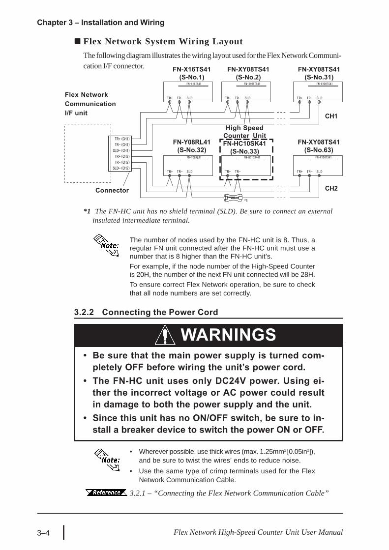
The number of nodes used by the FN-HC unit is 8. Thus, aregular FN unit connected after the FN-HC unit must use anumber that is 8 higher than the FN-HC unit’s.For example, if the node number of the High-Speed Counteris 20H, the number of the next FN unit connected will be 28H.To ensure correct Flex Network operation, be sure to checkthat all node numbers are set correctly.
3.2.1 – “Connecting the Flex Network Communication Cable”
FN-XY08TS41(S-No.63)
WARNINGS
*1
3.2.2 Connecting the Power Cord
Flex Network System Wiring LayoutThe following diagram illustrates the wiring layout used for the Flex Network Communi-cation I/F connector.
*1 The FN-HC unit has no shield terminal (SLD). Be sure to connect an externalinsulated intermediate terminal.

3–5Flex Network High-Speed Counter Unit User Manual
Chapter 3 – Installation and Wiring
If the cables cannot be separated, use shielded cables andground the shield line.
If the wires must be placed in the same duct, separate them via an earthed/groundeddivider.
Earth/Ground
GroundedSeparators
Duct(non-conductingresin/plastic)
CommunicationCables
PowerCables
RegularControl Lines
3.2.3 General Cautions
To help prevent noise and interference problems, separate all communication lines frompower lines by placing them in a separate duct.
• Use noice-reducing external wiring methods to increase overall sys-tem reliability.
• To prevent power surges or noise interference, use ducts to sepa-rate all DC I/O or current circuit wires from communication cables.
• To prevent malfunctions due to noise, communication cables mustbe wired separately from high-frequency lines and power lines suchas high-voltage lines, high-current lines, and inverters.
Duct forCommunication
Lines
Duct for RegularControl Lines
Duct forPower Lines

3–6 Flex Network High-Speed Counter Unit User Manual
Memo

4–1Flex Network High-Speed Counter Unit User Manual
4.1 Operation Mode
Chapter4 Functional Specifications
1. Operation Mode2. Functions
There are two operation modes — RUN Mode and Setting Mode — which can beswitched using bit 14 and bit 15 of the Control (CTL) register. If two 16-bit up countersare used, the modes in each counter can be changed.RUN ModeThe current value of the counter can be read. Commands cannot be used, however, tosend read/write data to the FN-HC unit.Setting ModeIn this mode, commands can be used to read/write data to the FN-HC unit. While inSetting Mode, FN-HC unit count input is not changed, however, output control isperformed based on this count data.When performing data Write in RUN mode, both the GLC unit and the FN-HCunit must be set to the same mode. If they are not, a malfunction can occur.
GLC Setting Mode
RUN Mode
FN-HC Unit
Data Write
Data Read
Count Condition Change
Count Condition
• Even in Setting Mode, the output produced will depend on the currentsetting value. for example, if the Current Value is equal to the ComparatorOutput Value, the Comparator Output turns ON. Also, When the CurrentValue is inside the Dog Setting Range, the Cam Switch Output will turn ON.
• After turning the FN-HC unit’s power OFF, all write data is reset to itsinitial values. In this case, be sure to reset all write data.

4–2 Flex Network High-Speed Counter Unit User Manual
Chapter 4 – Functional Specifications
Counter TypesYou can choose one of the following three types of counters:• 16-bit Up Counter – counts in ascending order within a 16-bit range. These two
counters operate independently.• 32-bit up counter – counts in ascending order within a 32-bit range.• 32-bit up/down counter – counts in both ascending and descending order within a
32-bit range.
Counter FunctionsYou can choose one of the following three types of functions. When using the 16-bit upcounter X 2, you can select a counter function for each of the two independent counters.• Linear counter – counts up to and maintains the maximum counting value.• Ring counter – counts between the Ring Counter’s upper and lower limit values.
After counting from the lower limit value to the upper limit value, the counter returnsto the lower limit value and begins to count again.
• Frequency counter – continuously displays the frequency.
4.2 Functions
Mode 1 Mode 2 Modes3 & 4
16-bitup counter
x 2
32-bitup counter
x 1
32-bitup/down
counter x 11 Counter Functions O O O2 Pulse Count Method X X O3 Measurement Speed O O O4 Input Type X X O5 Simultaneous Comparator Output O O X6 Cam Switch Output X X O7 Preset O O O8 Reset O O O9 Overflow Alarm O O O
10 Count Disable O O O11 Current Value Read O O O
Counter TypesNo.
The following settings are performed via the following dialog box.
For Flex Network Driver settings information, refer to the Pro-Control Editoror LT Editor On-line Help.
4–3Flex Network High-Speed Counter Unit User Manual
Chapter 4 – Functional Specifications
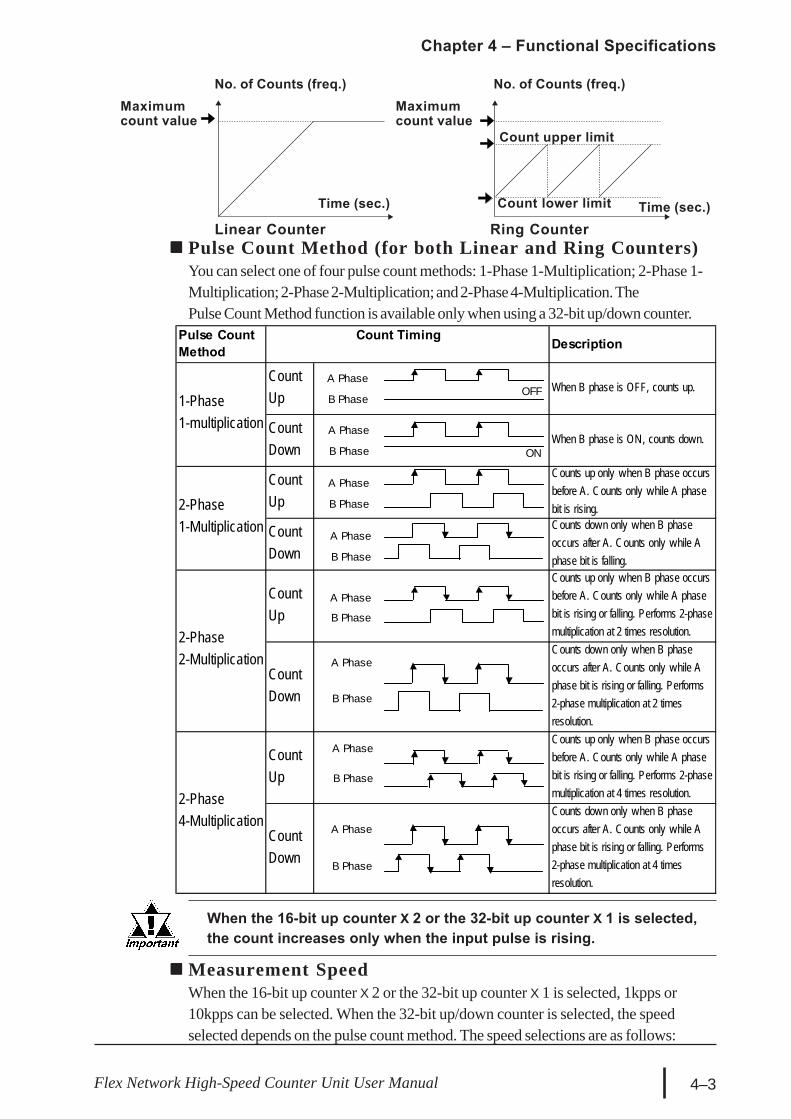
No. of Counts (freq.)Maximumcount value
Linear Counter Ring Counter
Count upper limit
Maximumcount value
Count lower limitTime (sec.) Time (sec.)
No. of Counts (freq.)
Pulse Count Method (for both Linear and Ring Counters)You can select one of four pulse count methods: 1-Phase 1-Multiplication; 2-Phase 1-Multiplication; 2-Phase 2-Multiplication; and 2-Phase 4-Multiplication. ThePulse Count Method function is available only when using a 32-bit up/down counter.
When the 16-bit up counter X 2 or the 32-bit up counter X 1 is selected,the count increases only when the input pulse is rising.
Pulse CountMethod Description
CountUp
When B phase is OFF, counts up.
CountDown
When B phase is ON, counts down.
CountUp
Counts up only when B phase occursbefore A. Counts only while A phasebit is rising.
CountDown
Counts down only when B phaseoccurs after A. Counts only while Aphase bit is falling.
CountUp
Counts up only when B phase occursbefore A. Counts only while A phasebit is rising or falling. Performs 2-phasemultiplication at 2 times resolution.
CountDown
Counts down only when B phaseoccurs after A. Counts only while Aphase bit is rising or falling. Performs2-phase multiplication at 2 timesresolution.
CountUp
Counts up only when B phase occursbefore A. Counts only while A phasebit is rising or falling. Performs 2-phasemultiplication at 4 times resolution.
CountDown
Counts down only when B phaseoccurs after A. Counts only while Aphase bit is rising or falling. Performs2-phase multiplication at 4 timesresolution.
2-Phase4-Multiplication
Count Timing
1-Phase1-multiplication
2-Phase1-Multiplication
2-Phase2-Multiplication
OFF
ON
A Phase
B Phase
A Phase
B Phase
A Phase
B Phase
A Phase
B Phase
A Phase
B Phase
A Phase
B Phase
A Phase
B Phase
A Phase
B Phase
Measurement SpeedWhen the 16-bit up counter X 2 or the 32-bit up counter X 1 is selected, 1kpps or10kpps can be selected. When the 32-bit up/down counter is selected, the speedselected depends on the pulse count method. The speed selections are as follows:

4–4 Flex Network High-Speed Counter Unit User Manual
Chapter 4 – Functional Specifications
Ring Counter FunctionThe Ring Counter function counts repeatedly between the lower limit value and theupper limit value. These limits are set in the Command setting.The ring counter can be used to control conditions, such as constant feed.
Ring Counter Function – ExampleA ring counter can be used in a system designed to cut a continuously-fed sheet, fromthe roller, at a value set by the ring counter.The Ring Counter functions as follows:1. The upper limit value and the lower limit value are set.2. The motor turns ON and the roller rotates.3. When the roller rolls out a specified length of sheet, the simultaneous ring counter
output causes the motor to turn OFF.4. The blade cuts the sheet.5. Steps 2 to 4 are repeated.
Differential Input (Line Drivers) DC Input (Open Collector)1-Phase1-Multiplication 50kpps or 200kpps 1kpps or 3kpps
2-Phase1-Multiplilcation 50kpps or 200kpps 1kpps or 3kpps
2-Phase2-Multiplication 25kpps or 100kpps 0.5kpps or 1.5kpps
2-Phase4-Multiplication 12.5kpps or 50kpps 0.25kpps or 0.75kpps
Input Type Pulse CountMethod
When using the 16-bit up counter X 2, the measurement speedmust be the same for both counters.
Input TypeYou can select an input type from either the line driver or the open collector. This featureis available only when a 32-bit up/down counter is selected.

4–5Flex Network High-Speed Counter Unit User Manual
Chapter 4 – Functional Specifications
Comparator Output Function (for both Linear and Ring Counters)When the current count value of the FN-HC unit equals the previously set ComparatorOutput setting, the FN-HC unit can perform simultaneous external output. Once theexternal output is produced, the unit will latch (will retain the output) until the Reset orPreset command is used.
The Comparator Output setting must be entered in the Write Dataregister.
ExplanationWhen the FN-HC unit’s current value matches the FN-HC unit’s user-specified previ-ously set count value, Comparator Output is produced. Since there is no effect from theGLC’s scan time, high-precision high-speed times as small as 1msec. can be used.Using the Comparator Output function requires that bit 8 and bit 9 of the Control (CTL)register be turned ON.
Comparator Output Function – ExampleIn a factory-processing system, the manufacture of a product corresponds to thecomparator output in each processing operation.1. Material is moved via the motor.2. The encoder gives the current value of the pulse, which corresponds to the current
position of the material.3. When the material moves into its specified position, the High-Speed Counter unit
produces the comparator output.
Encoder
MaterialSaw
Because the Comparator Output and the Cam Switch Output functions are set in andprocessed by the FN-HC unit, regardless of the GLC unit’s sequence program scantime, these functions can process at high speeds (max. 1ms).

4–6 Flex Network High-Speed Counter Unit User Manual
Chapter 4 – Functional Specifications
Cam Switch Output Function (both Linear and Ring Counters)The High-Speed Counter unit performs external output only when its count value is setwithin the range of a cam switch’s dog. Two (2) imaginary cam switches operating viasoftware can be used. Each switch can set up to eight (8) dogs.
Cam Switch 1 Setting Example Output Range 1) Cam switch 1 Output Dog 1 Lower limit: 51 Upper limit: 54 2) Cam Swtich 1 Output Dog 2 Lower limit: 104 Upper limit: 106
Cam Switch 2 Setting Example Output Range 1) Cam switch 2 Output Dog 1 Lower limit: 50 Upper limit: 53 2) Cam Swtich 2 Output Dog 2 Lower limit: 101 Upper limit: 103 3) Cam Swtich 2 Output Dog 3 Lower limit: 107 Upper limit: 108
• When counting up (during reverse movement), reaching theupper limit turns the Switch ON, and the lower limit turns it OFF.
• Set start and end points to zero for unused dogs.
Cam Switch 2 Output
Count Input
Cam Switch 1 Output
RUN Mode /Setting Mode Switch
(Control/CTL bit 14)
1 2 50 51 52 53 54 55 101 102 103 104 105 106 107 108
(1) (2)
(1) (2)OFF
Operation of Comparator Output Function
Comparator Output(when the Comparator Output is set to 100)RUN Mode / Setting Mode
Switch (Control/CTL bit 14, 15)
Comparator Output EnableSwitch (Control/CTL bit 8, 9)
ON
ON
Comparator OutputON
..... 98 99 100 101 .....
Count Input
ON
ON
ON
OFF
OFF
OFF
OFF
OFF
(3)
RESET(CTL bits 0, 1)
*1
*1 At a communication speed of 6Mbps with 63 nodes (Stations), allow at least 6ms for RESETto turn all comparator outputs OFF. 8 nodes would be approx. 2ms. (Comm. + Output delay)
(Up to 8 ouput settings can be used for each cam)

4–7Flex Network High-Speed Counter Unit User Manual
Chapter 4 – Functional Specifications
Preset Function (both Linear and Ring Counters)By turning the Preset command ON, you can change the High-Speed Counter unit’scurrent count values to preset values.
• Preset values must be entered in the Write Data register before usingthe Preset Function.
• When using Setting Mode, the Preset feature cannot be used.
ExplanationThe Preset Function enters a user-specified numeric value (preset value) from thecurrent counter value.The Preset Function is used when the pulse count starts from a user-specified value.Another feature of the Preset Function is that it can also be set with a Logic Program.
Preset Function Usage – ExampleUsing the Preset Function allows a product-counting system to continue from theprevious day’s production count.1. Products are carried by a loader.2. An encoder gives the current value of the pulse, which corresponds to the number of
products and the distance each product is carried.3. At the end of the day’s production, the buffer memory for that day’s last successful
current count value is stored in the retentive variable.Operation of Preset Function(Preset to 100)
RUN Mode /Setting Mode Switch
(Control/CTL bit 14, 15)
ON
Count Input
Preset Command(Control/CTL bit 2, 3) ON
1 2 3 50 51 100 101 .....
OFF
OFF
ONOFF
Because the Comparator Output and the Cam Switch Output functions are set in andprocessed by the High-Speed Counter unit, regardless of the GLC unit’s sequenceprogram scan time, these functions can process at high speeds (max. 1msec).
• Set the Cam Switch Output Range so that the dog’s lower limit and up-per limit values have at least three (3) seconds gap between them.
• Set the Cam switch Output Range from -2147483392 (0x80000100) to2147483391 (0x7FFFFEFF).
• Set the Cam Switch Ouput Range so that the Dog upper and lower limitvalue range is less than 2147483647 (0x7FFFFFFF).

4–8 Flex Network High-Speed Counter Unit User Manual
Chapter 4 – Functional Specifications
Reset Function (both Linear and Ring Counters)You can reset the unit’s current count value to its initial value. The comparator outputand the cam switch output are reset to 0 (OFF). The initial value for a Linear Counter iszero, and the initial value for a Ring Counter is minimum value.
During Setting Mode, the Reset Feature cannot be used.
Overflow Alarm Function (Ring Counter only)When a counter reaches the maximum value, the overflow flag turns ON. To turn OFFthe overflow flag, use either the Preset command or Reset function. The OverflowAlarm Function feature is available only when the counter function is set as a LinearCounter.
Count Disable Function (both Linear and Ring Counters)When the Setting Mode is selected, the High-Speed Counter unit’s count function canbe temporarily stopped. After reselecting RUN Mode, the count value resumes from thetime the count stopped — when the Setting Mode was selected. Only while the SettingMode is selected can each setting be entered with the Write Data register.
Current Value Read Function (both Linear and Ring Counters)The current value output by a High-Speed Counter unit can be read at every scan.
When the Setting Mode is selected, the current value is notupdated, but is retained until the RUN Mode resumes.
1. When a GLC unit’s 32-bit up counter uses a decimal format setting, andbecause the MSB of the 32-bit variable is a sign bit, the number that follows+2147483647 is –2147483648.
Type of Counter Initial Value Minimum Value Maximum Value0 (decimal) 0 (decimal) 65535 (decimal)0h (hexadecimal) 0h (hexadecimal) FFFFh (hexadecimal)0 (decimal) 0 (decimal) -1 (decimal)*1
0h (hexadecimal) 0h (hexadecimal) FFFFh (hexadecimal)0 (decimal) -2147483648 (decimal) 2147483647 (decimal)0h (hexadecimal) 80000000h (hexadecimal) 7FFFFFFFh (hexadecimal)
16-bit up counter x 2
32-bit up counter
32-bit up/down counter

5–1Flex Network High-Speed Counter Unit User Manual
5.1 Flex Network Driver Settings
Chapter5 Data Settings
1. Flex Network Driver Settings
2. Data Settings
The use of integer variables depends on the integer variable allocated to each treestructure terminal in the Flex Network Driver.When using GLC2000 series/LT series, integer variables can be allocated in GP-PRO/PBIII C-Package (Pro-Control Editor) or LT Editor. For details of each setup method,refer to each Editor’s online Help.When using GP3000 series, refer to GP-Pro EX Reference Manual.
<GLC2000/LT Series> <GP3000 Series>
The use of integer variables allocated to each terminal are as follows:STA : Status registerCTL : Control registerCMD : Command registerRD : Read Data registerWD : Write Data registerCV1 : Current Value (Counter 1)CV2 : Current Value (Counter 2)
• CV2 is displayed only when the setting is the 16-bit upcounter X 2.
• If variables are not allocated to all terminals, an error mes-sage will occur at the time of error check or download.
• The above-listed variable/registers are examples of pro-gram variables.
When setting up the I/O configuration, prior to starting the Logic Pro-gram, or while the program is being executed, when the I/O configura-tion is used to change the type of counter or function, depending onthe command used, the written data may be reset to its initial value.When the FN-HC unit’s power is turned ON, this data is written to theFN-HC unit.

5–2 Flex Network High-Speed Counter Unit User Manual
Chapter 5 – Data Settings
Status Register (STA)Stores bit information, such as the High-Speed Counter unit’s status.Each bit is used as follows:
Reserved locations cannot be used.
BitPosition Description 16-bit up
counter X 232-bit upcounter
32-bitup/downcounter
Note
Comparator Output (Counter 1)0: No Output; 1: Output O O X Reads out Comparator Output 1's status
to the Logic Program.Cam Switch Output 10: No Output; 1: Output X X O Reads out Cam Switch 1's status to the
Logic Program.Comparator Output (Counter 2)0: No Output; 1: Output O O X Reads out Comparator Output 2's status
to the Logic Program.Cam Switch Output 20: No Output; 1: Output X X O Reads out Cam Switch 2's status to the
Logic Program.
2 Overflow Flag (Counter 1)0: OFF; 1: ON O O O Reads out Counter 1's overflow status to
the Logic Program.
3 Overflow Flag (Counter 2)0: OFF; 1: ON O X X Reads out Counter 2's overflow status to
the Logic Program.
4 CW/CCW Rotate Notification0: CCW; 1: CW O O O
Reads out Count Up direction (CW,Count Down direction (CCW) to theLogic Program.
5 Reserved – – – –6 Reserved – – – –7 Reserved – – – –
Comparator Output Check(Counter 1)0: Disable; 1: Enable
O O XReads out Counter 1's ComparatorOutput Use/Not Use status to the LogicProgram.
CW Rotate Check(Cam Switch 1)0: Disable; 1: Enable
X X OWhen Cam SW1 is used, reads out CWOutput Use/Not Use status to the LogicProgram.
Comparator Output Check(Counter 2)0: Disable; 1: Enable
O X XReads out Counter 2's ComparatorOutput Use/Not Use status to the LogicProgram.
CCW Rotate Check(Cam Switch 1)0: Disable; 1: Enable
X X OWhen Cam SW1 is used, reads outCCW Output Use/Not Use status to theLogic Program.
10CW Rotate Check(Cam Switch 2)0: Disable; 1: Enable
X X OWhen Cam SW2 is used, reads out CWOutput Use/Not Use status to the LogicProgram.
11CCW Rotate Check(Cam Switch 2)0: Disable; 1: Enable
X X OWhen Cam SW2 is used, reads outCCW Output Use/Not Use status to theLogic Program.
12 Reserved – – – –13 Command Completion Flag O O O Confirms sending of CMD is completed.
14RUN Mode / Setting ModeSwitch (Counter 1)0: RUN Mode; 1: Setting Mode
O O O Reads out Counter 1's mode selection tothe Logic Program.
15RUN Mode / Setting ModeSwitch (Counter 2)0: RUN Mode; 1: Setting Mode
O X X Reads out Counter 2's mode selection tothe Logic Program.
0
1
8
9

5–3Flex Network High-Speed Counter Unit User Manual
Chapter 5 – Data Settings
ModesAvailable
BitLocation Description
16-bitup
counterX 2
32-bitup
counter
32-bitup/downcounter
Note
0 Reset (Counter 1) O O O Requests Counter 1 Reset1 Reset (Counter 2) O X X Requests Counter 2 Reset2 Preset Command (Counter 1) O O O Requests Counter 1 Preset3 Preset Command (Counter 2) O X X Requests Counter 2 Preset4 Reserved – – –5 Reserved – – –6 Reserved – – –7 Reserved – – –
Comparator Output(Counter 1)0: Disable; 1: Enable
O O X Requests Comparator OutputEnable/Disable for Counter 1
CW Direction(Cam Switch 1)0: Disable; 1: Enable
X X ORequests CW Enable setting forCam SW 1. CCW can also be setsimultaneously.
Comparator Output(Counter 2)0: Disable; 1: Enable
O X X Requests Comparator OutputEnable/Disable for Counter 2
CCW Rotate(Cam Switch 1)0: Disable; 1: Enable
X X ORequests CCW Enable setting forCam SW 1. CW can also be setsimultaneously.
10CW Rotate(Cam Switch 2)0: Disable; 1: Enable
X X ORequests CW Enable setting forCam SW 2. CCW can also be setsimultaneously.
11CCW Rotate(Cam Switch 2)0: Disable; 1: Enable
X X ORequests CCW Enable setting forCam SW 2. CW can also be setsimultaneously.
12 Reserved – – –13 Reserved – – –
14
RUN Mode / Setting ModeSwitch (Counter 1)0: RUN Mode; 1: SettingMode
O O O Requests RUN Mode or SettingMode for Counter 1.
15
RUN Mode / Setting ModeSwitch (Counter 2)0: RUN Mode; 1: SettingMode
O X X Requests RUN Mode or SettingMode for Counter 2.
8
9
–
–
Enabled inRUN orSettingMode
–
Enabledonly during
SettingMode
Enabled inRUN orSettingMode
–
Control Register (CTL)Used to control the High-Speed Counter unit’s operation.Each bit is used as follows:
• When the process has completed, the Reset and Presetcommands will turn OFF.
• Bits 8 to 11 are available only while the unit is operating inSetting Mode.
• Reserved locations cannot be used.
Even when bits 8 to 11 are disabled in setting mode, output is not turnedOFF. The Reset and Preset commands will turn output OFF.

5–4 Flex Network High-Speed Counter Unit User Manual
Chapter 5 – Data Settings
1. Available only with the 16-bit up counter X 2.2. Available only with the ring counter function.3. Available only with the 16-bit up counter X 2 or the 32-bit up counter.4. Available only with the 32-bit up/down counter.
Command Register (CMD)Used when data is written to the High-Speed Counter unit or when the unit’s data isread. This register is used together with either a WD or RD register.Prior to using a command, be sure to confirm that the FN-HC is in Setting Mode. Eachcommand is requested once. If a command needs to be repeated, repeat thecommand’s request for the desired number of times. Example
When writing a Preset value, enter “1” as the “CMD”.When reading a Preset value, enter “129” as the “CMD”.
The following commands are use in the same way.
Be sure to set the Cam Switch Output Range so that the dog’s lower limitand upper limit values have at least three (3) seconds gap between them.
WriteCommand
ReadCommand Description Initial Value
1 (01h) 129 (81h) Preset Value (Counter 1) 02 (02h) 130 (82h) Preset Value (Counter 2)*1 03 (03h) 131 (83h) Ring Counter Lower Limit (Counter 1)*2 Cntr. Min. value.4 (04h) 132 (84h) Ring Counter Upper Limit (Counter 1)*2 Cntr. Max. value.5 (05h) 133 (85h) Ring Counter Lower Limit (Counter 2)*1,*2 Cntr. Min. value.6 (06h) 134 (86h) Ring Counter Upper Limit (Counter 2)*1,*2 Cntr. Max. value.7 (07h) 135 (87h) Comparator Output Value (Counter 1)*3 08 (08h) 136 (88h) Comparator Output Value (Counter 2)*1 09 (09h) 137 (89h) Dog 1 Lower Limit of Cam Switch 1*4 010 (0Ah) 138 (8Ah) Dog 1 Upper Limit of Cam Switch 1*4 011 (0Bh) 139 (8Bh) Dog 2 Lower Limit of Cam Switch 1*4 012 (0Ch) 140 (8Ch) Dog 2 Upper Limit of Cam Switch 1*4 013 (0Dh) 141 (8Dh) Dog 3 Lower Limit of Cam Switch 1*4 014 (0Eh) 142 (8Eh) Dog 3 Upper Limit of Cam Switch 1*4 015 (0Fh) 143 (8Fh) Dog 4 Lower Limit of Cam Switch 1*4 016 (10h) 144 (90h) Dog 4 Upper Limit of Cam Switch 1*4 017 (11h) 145 (91h) Dog 5 Lower Limit of Cam Switch 1*4 018 (12h) 146 (92h) Dog 5 Upper Limit of Cam Switch 1*4 019 (13h) 147 (93h) Dog 6 Lower Limit of Cam Switch 1*4 020 (14h) 148 (94h) Dog 6 Upper Limit of Cam Switch 1*4 021 (15h) 149 (95h) Dog 7 Lower Limit of Cam Switch 1*4 022 (16h) 150 (96h) Dog 7 Upper Limit of Cam Switch 1*4 023 (17h) 151 (97h) Dog 8 Lower Limit of Cam Switch 1*4 024 (18h) 152 (98h) Dog 8 Upper Limit of Cam Switch 1*4 0

5–5Flex Network High-Speed Counter Unit User Manual
Chapter 5 – Data Settings
1. Available only with the 32-bit up/down counter.
Command List (cont.)
Read Data Register/RD (Enabled in Setting Mode)Stores data when the command to read data from the High-Speed Counter unit isentered. Also, stores data written after the command to write data to the High-SpeedCounter unit is entered.
Write Data Register/WD (Enabled in Setting Mode)Stores data before the command to write data to the High-Speed Counter unit isentered.
Current Value/CV1Normally used to store the current count value of Counter 1.
Current Value/CV2Normally used to store the current count value of Counter 2.
• After turning the FN-HC unit’s power OFF, all write data is reset to itsinitial values. In this case, be sure to reset all write data.
• Be sure to set the Cam Switch Output Range so that the dog’s lowerlimit and upper limit values have at least three (3) seconds gap be-tween them.
WriteCommand
ReadCommand Description Initial Value
25 (19h) 153 (99h) Dog 1 Lower Limit of Cam Switch 2*1 026 (1Ah) 154 (9Ah) Dog 1 Upper Limit of Cam Switch 2*1 027 (1Bh) 155 (9Bh) Dog 2 Lower Limit of Cam Switch 2*1 028 (1Ch) 156 (9Ch) Dog 2 Upper Limit of Cam Switch 2*1 029 (1Dh) 157 (9Dh) Dog 3 Lower Limit of Cam Switch 2*1 030 (1Eh) 158 (9Eh) Dog 3 Upper Limit of Cam Switch 2*1 031 (1Fh) 159 (9Fh) Dog 4 Lower Limit of Cam Switch 2*1 032 (20h) 160 (A0h) Dog 4 Upper Limit of Cam Switch 2*1 033 (21h) 161 (A1h) Dog 5 Lower Limit of Cam Switch 2*1 034 (22h) 162 (A2h) Dog 5 Upper Limit of Cam Switch 2*1 035 (23h) 163 (A3h) Dog 6 Lower Limit of Cam Switch 2*1 036 (24h) 164 (A4h) Dog 6 Upper Limit of Cam Switch 2*1 037 (25h) 165 (A5h) Dog 7 Lower Limit of Cam Switch 2*1 038 (26h) 166 (A6h) Dog 7 Upper Limit of Cam Switch 2*1 039 (27h) 167 (A7h) Dog 8 Lower Limit of Cam Switch 2*1 040 (28h) 168 (A8h) Dog 8 Upper Limit of Cam Switch 2*1 0
254 (FEh) Error Code Read255 (FFh) Version Read

5–6 Flex Network High-Speed Counter Unit User Manual
Chapter 5 – Data Settings
When you enter a Write command value in the Command (CMD) register, the WDvalue is written as data to the High-Speed Counter unit.
5.2 Data Settings
Data Write
Data settings are performed in the Setting Mode. Mode changes are controlled via theControl (CTL) bits 14 and 15. 4.1 – “Operation Mode”
If the WD register contains a value that is outside the allow-able Write command range, and the CMD register has beenset to a Write command, the maximum or minimum value willbe written to the High-Speed Counter unit.
Values written to the FN-HC unit are set in the Write Data (WD) register.
• When data containing more than 16 bits is written to data designated as16-bit, the 16-bit data will be overwritten.
• After turning the FN-HC unit’s power OFF, all write data is reset to itsinitial values. In this case, be sure to reset all write data.
If a Read command is set in the Command (CMD) register, values that are read fromthe High-Speed Counter unit are stored in the Read Data (RD) register.
• When an incorrect value is entered to the command (SMD)setting, that value will remain unchanged, in the register.
• When commands can be accepted, Bit 13 (CommandCompleted Flag) and the command value input will bothbe cleared (set to “0”).
Data Read
Values written to the FN-HC unit will be reflected in the RD command.Also, when command write is completed, it can be confirmed via the status area’s bit 13(Command Completed Flag), which will turn ON.
• When an incorrect value is entered to the command (SMD)setting, that value will remain unchanged, in the register.
• When commands can be accepted, Bit 13 (CommandCompleted Flag) and the command value input will bothbe cleared (set to “0”).
Also, when command read is completed, it can be confirmed via the status area’s bit 13(Command Completed Flag), which will turn ON.
When performing data Write in RUN mode, both the GLC unit and the FN-HCunit must be set to the same mode. If they are not, a malfunction can occur.

5–7Flex Network High-Speed Counter Unit User Manual
Chapter 5 – Data Settings
High Speed Counter Command FlowData Write to Ring Counter Upper/Lower Limit Values
Change to Setting Mode
(CTL bits 14, 15)Setting Mode
RUN Mode
Status Check
(STA bits 14, 15)
Ring counter Upper Limit or LowerLimit WD
Ring Counter Upper limit/Lower limitCommand Send/CMD
Command Complete Check/ Status(bit 13)
Check new Ring Counter value/RD
1)
2)
3)
4)
5)
6) Reflected in Status(STA)
Input of Ring Counter Upper Limit(Integer) or Lower Limit (Integer)
0 Clear
Ring Counter
Value
Depending onthe driver used,when the nextcommand isissued, this willturn OFF.
A
A
3: Counter 1 Lower limit
4: Counter2 Upper limit
5: Counter 2 Lower limit
6: Counter 2 Upper limit
The Flex Network Driver contains the RESET signal. All setting and reset-ting of all other signals is performed via the user’s software.
Since the upper limit andlower limit cannot be in-put at the same time, youwill need to repeat certainoperations.
Setting Mode
RUN Mode
1. Set WD register to a value. 1. Enter a Read command in the2. Enter a Write command in the CMD register.
CMD register.
Data is written to the High-speed Counter unit.
Data is read from the High-speed Counter unit to the RD register.
Write Read
Data Setting Procedures

5–8 Flex Network High-Speed Counter Unit User Manual
Chapter 5 – Data Settings
Comparator Output Value/Enable & Disable Changeover Settings
Change to Setting Mode
(CTL bits 14, 15)Setting Mode
RUN Mode
Status Check
(STA bits 14, 15)
Write Comparator Output Value WD
Comparator Output value CommandSend/CMD
Command Complete Check/ STA(bit 13)
Check new Ring Counter value/RD
1)
2)
3)
4)
5)
6) Reflected in Status(STA)
Comparator Output Value (Integer)
0 Clear
Ring Counter Value
Depending onthe driver used,when the nextcommand isissued, this willturn OFF.
A
A
Since the Counter 1 Compara-tor Output va lue and theCounter 2 Comparator Outputvalue cannot be written at thesame time, you will need to re-peat certain operations.
Setting Mode
RUN Mode
Ring Counter Upper limit/Lower limitCommand Send/CMD
7 (or 8)
Comparator Output Enable ChangeoverRUN Command/CTL (CTL bits 8, 9)
High-Speed Counter Operation
A
Comparator OutputEnable ProcessingCompleted
*1
Enable
DisablePerform this code in Compara-tor Output Enable ChangeoverRUN Command Setting Mode
*1 At a communication speed of 6Mbps with 63 nodes (Stations), allow at least 5msfor RESET to turn all Comparator Outputs OFF. 8 nodes would be approx. 1ms.
The Flex Network Driver contains the RESET signal. All setting and reset-ting of all other signals is performed via the user’s software.
The above procedures describe writing a Comparator Ouput Value to theFN-HC unit. However, while entering the above data is possible, it doesnot provide functionality for this feature.
To use the above data for the Comparator Value Count Up Output, use thefollowing Comparator Output Enable Changeover to enable output.

5–9Flex Network High-Speed Counter Unit User Manual
Chapter 5 – Data Settings
Cam Switch Dog Value Write & Direction Change and Enable/DisableChangeover Settings
Change to Setting Mode
(CTL bits 14, 15)Setting Mode
RUN Mode
Status Check
(STA bits 14, 15)
Cam Switch Dog Value Write/ WD
Cam Switch Dog Command Send/CMD
Command Complete Check/ STA(bit 13)
Check new Dog Value/RD
1)
2)
3)
4)
5)
6) Reflected in Status(STA)
Dog Value (Integer)
0 Clear
Dog Value
Depending onthe driver used,when the nextcommand isissued, this willturn OFF.
A
A
The Flex Network Driver contains the RESET signal. All setting and reset-ting of all other signals is performed via the user’s software.
Since only one Dog Value can bewritten at one time, you will needto repeat certain operations towrite multiple Dog Values.
Setting Mode
RUN Mode
Dog Values from 9 to 40 can be written to theCommand Register
9 to 40
Cam switch RUN Command/CTL(CTL bits 8, 9, 10, 11)
High-Speed Counter Operation
A
*1
Enable
Disable
Perform the Cam Switch RUNCommand in Setting Mode
*1 At a communication speed of 6Mbps with 63 nodes (Stations), allow at least 5msfor RESET. 8 nodes would be approx. 1ms.
The above procedures describe writing a Dog Value to the FN-HC unit.However, while entering the above data is possible, it does not providefunctionality for the Cam Switch Output feature.
To use the above Dog Value Setting data for simultaneous output, use thefollowing Cam Switch RUN Command to enable the Cam Switch.

5–10 Flex Network High-Speed Counter Unit User Manual
Chapter 5 – Data Settings
Preset Value Write and Preset RUN
Change to Setting Mode
(CTL bits 14, 15)Setting Mode
RUN Mode
Status Check
(STA bits 14, 15)
Preset Value Write/ WD
Preset Command Send/CMD
Command Complete Check/ STA(bit 13)
Check new Preset Value/RD
1)
2)
3)
4)
5)
6) Reflected in Status(STA)
Preset Value (Integer)
0 Clear
Preset Value
Depending onthe driver used,when the nextcommand isissued, this willturn OFF.
A
A
The Flex Network Driver contains the RESET signal. All setting and reset-ting of all other signals is performed via the user’s software.
Since only one Preset Value canbe written at one time, you willneed to repeat certain operationsto write multiple Preset Values.
Setting Mode
RUN Mode
Preset Write Requests to the CommandRegister can be “1” or “2”.
1 (or 2)
Preset Command/CTL
(CTL bits 2, 3)
High-Speed Counter OperationPreset ProcessingCompleted
*1
Enable
Disable
Only enabled in PresetCommand RUN mode.
*1 At a communication speed of 6Mbps with 63 nodes (Stations), allow at least 5msfor RESET. 8 nodes would be approx. 1ms.
User Software Driver
The above procedures describe writing a Preset Value to the FN-HC unit.However, while entering the above data is possible, it does not providefunctionality for the Preset command.
To use the above Preset data for simultaneous output, use the followingPreset Command to enable the Preset feature.

5–11Flex Network High-Speed Counter Unit User Manual
Chapter 5 – Data Settings
Control
(CTL bits 0, 1)
High-Speed Counter Operation
Reset Completed
*1
User Software
(1 scan)
Left and right are not performed inSetting and RUN modes.
User Software Driver
Reset
*1 At a communication speed of 6Mbps with 63 nodes (Stations), allow at least 5msfor RESET. 8 nodes would be approx. 1ms.

5–12 Flex Network High-Speed Counter Unit User Manual
Memo

6–1Flex Network High-Speed Counter Unit User Manual
This section describes the Flex Network system’s error messages and countermeasures.
Chapter6 Problems and Solutions
6.1 Prior to Troubleshooting
Before reading this chapter’s “Troubleshooting Checklist” section for the cause(s) ofa unit’s problem, first identify the type of problem itself, and then check other basicitems.Flex Network errors are classified, as follows, into three types of errors:1. Logic Program Error
The logic program does not run (GLC status LED: Green is not lit).2. Flex Network I/F Error
Communication cannot be performed with any Flex Network unit.3. Flex Network Unit Error
Flex Network unit cannot input or output signals.
Check ItemsAfter completing your preliminary check, and before troubleshooting for the cause(s) ofa unit’s problem, be sure to check the following items:• Is the correct power voltage supplied to the GLC and Flex Network units?• Is the power supplied to the GLC and Flex Network units within the allowable
voltage range?• Are all connected cable wiring and connections (communication cable, I/O cable)
secure and correct?• Are any Flex Network unit terminals loose or disconnected?• Are all Flex Network unit switches (S-No. switch, dip switch, terminal switch) set
correctly?• Is the required communication cable being used?
4. Troubleshooting for GP3000Series
1. Prior to Troubleshooting2. Error Code Display3. Troubleshooting for GLC2000/
LT Series

Chapter 6 – Problems and Solutions
6–2 Flex Network High-Speed Counter Unit User Manual
6.2 Error Code Display
By displaying an error code on the GLC screen with using the system variables thatindicate the I/O driver error codes, troubleshooting can be performed quickly.
Line Monitor
Production Control
Progress Monitor
Maintenance
Document Control
System Diagnosis
Model System VariableGLC2000/LT Series #IOStatusGP3000 Series #L_IOStatus
For GP3000 series, an error code is displayed in the systemwindow on the GP screen without using the system variables.
The following is an example of an error code display application.
Example Application1. Create an I/O System Diagnosis button.2. Create a ladder logic program that displays the system status as an error code when
the [System Diagnosis] button is pressed.
System Status
Error Occurred: Error Code: 841 Error Code (SystemVariable value) isdisplayed.

Chapter 6 – Problems and Solutions
6–3Flex Network High-Speed Counter Unit User Manual
YES
NOIs the I/Funit’s status LED
“RUN" lit ?
YES
Canthe logic
program be checked viathe Pro-Control
Editor?
6.3.1 Troubleshooting Checklist for GLC2000/LT Series
Use the following flowchart to locate the problem cause(s) and take appropriatecountermeasure(s).
Isthe GLC
unit’s green statusLED lit (notblinking)?
<Not lit>The GLC unit’s power has not been turned ON.Turn the power ON.
<Red LED is lit>A major error has occurred in the logic pro-gram. Check the logic program status.
<Green LED is lit>The logic program has not run. Activate thecontroller and run the logic program.
Pro-Control Editor OperationManual – Chapter 4LT Editor Operation Manual, LogicProgram Edition – Chapter 2Executing Logic Program
Wasthe “Use I/O”
check box selected beforethe logic program was
downloaded?
NO
YES
YES
NO
NO
YES
NO
NOIs Error code841 displayed?
YES
The Flex Networkunit is defective.Contact yourlocal distributorfor service.
Isan error
code displayed?
6.2 –“Error Code
Display”
Check the Pro-Control/LT Editor’s [RUN/STOP]window’s [Use I/O] check box, and then down-load the logic program to the GLC.
Pro-Control Editor OperationManual – Chapter 4LT Editor Operation Manual, LogicProgram Edition – Chapter 2 Execut-ing Logic Program
6.3 Troubleshooting for GLC2000/LT Series
6.3.2 Error Code List forGLC2000/LT Series
Chapter 6 – Problems and Solutions
6–4 Flex Network High-Speed Counter Unit User Manual
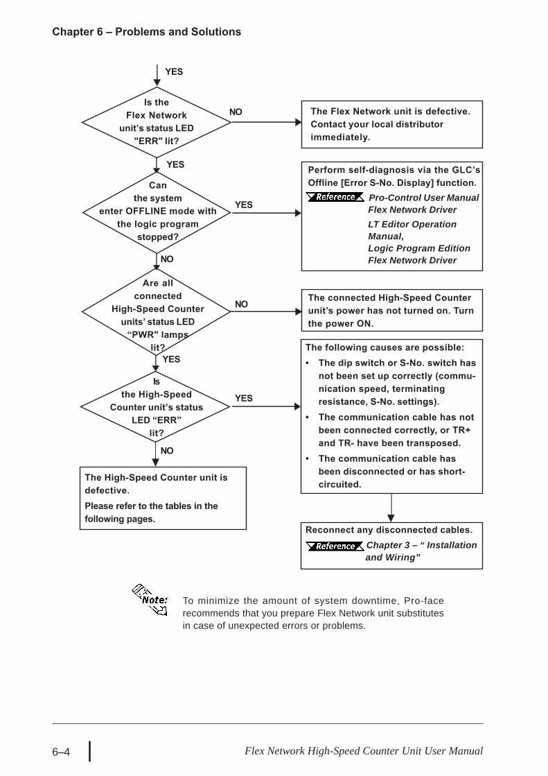
Reconnect any disconnected cables. Chapter 3 – “ Installation
and Wiring”
The following causes are possible:• The dip switch or S-No. switch has
not been set up correctly (commu-nication speed, terminatingresistance, S-No. settings).
• The communication cable has notbeen connected correctly, or TR+and TR- have been transposed.
• The communication cable hasbeen disconnected or has short-circuited.
The connected High-Speed Counterunit’s power has not turned on. Turnthe power ON.
YES
Is theFlex Network
unit’s status LED"ERR" lit?
NO
YES
The Flex Network unit is defective.Contact your local distributorimmediately.
YES
NO
Are allconnected
High-Speed Counterunits’ status LED
“PWR" lampslit?
NO
The High-Speed Counter unit isdefective.Please refer to the tables in thefollowing pages.
YES
Isthe High-Speed
Counter unit’s statusLED “ERR”
lit?
YES
NO
To minimize the amount of system downtime, Pro-facerecommends that you prepare Flex Network unit substitutesin case of unexpected errors or problems.
Canthe system
enter OFFLINE mode withthe logic program
stopped?
Perform self-diagnosis via the GLC’sOffline [Error S-No. Display] function.
Pro-Control User ManualFlex Network DriverLT Editor OperationManual,Logic Program EditionFlex Network Driver

Chapter 6 – Problems and Solutions
6–5Flex Network High-Speed Counter Unit User Manual
Condition Check Item SolutionIs the operation modeset to RUN Mode?
Set the RUN Mode / Setting Modeswitch (Control bits 14, 15) to ON.Failed to write initial set value.Either ST OP and RUN thecontroller, or turn the High-SpeedCounter unit OFF and then ON.If the condition is the same, thecommunication cable may bedisconnected or improperlyconnected, or the High-SpeedCounter unit may have failed.
845 in #IOST AT US?
Failed to write set value.Write set value again.If the condition is the same, thecommunication cable may bedisconnected or improperlyconnected, or the High-SpeedCounter unit may have failed.
Does the previous Command valueremain in CMD (has the value notc leared to 0)?
Check the values entered inthe Command (CMD) setting,and enter valid values.
Does the GLC display an error?
If the GLC unit displays an error, usethe troubleshooting section of thecorresponding GLC manual to setthe GLC unit to normal operation.
Are A Phase, B Phase, andPLS1/2 wired correctly?
Check and fix external wiring.
Is voltage directly appliedto pulse input terminals?
If the unit does not perform countoperation, check and fix the pulsegenerator and/or the external wiring.
Is the operation modeset to Setting Mode?
Set the RUN Mode and the SettingMode (CT L bits 14, 15) to OFF.
Has an overflow error occurred?Clear the overflow error byrunning Reset or Preset.
843 in #IOST AT US?
An error was detected in theHigh-Speed Counter unit.
6.3.2 – "Error Code List forGLC2000/LT Series"
844 in #IOST AT US?
Cannot write setvalue correctly
Does notperform countoperation
If you cannot find the source of the problem in this section’s “Troubleshooting”flowcharts, the High-Speed Counter unit itself may be the problem. Use the followingtable to take the appropriate problem-solving measures.
FN-HC Unit Troubleshooting Checklist

Chapter 6 – Problems and Solutions
6–6 Flex Network High-Speed Counter Unit User Manual
FN-HC Unit Troubleshooting Checklist (cont.)Condition Check Item Solution
Is 844 written to #IOSTATUS?
The read in of the initial value hasfailed. Turn the controller to STOP,then RUN, or turn the FN-HC unit'spower ON/OFF. IF the problemrepeats, check if the data transfercable is either cut, the connectoris loose or if the FN-HC unit isdamaged.
Does the input type of pulsematch the pulse input type inthe I/O configuration settings?
Match the input type of pulsewith the pulse input typein the I/O configuration.
Is the maximum speed ofinput pulses within the rangeof calculated speed set in theI/O configuration?
Correct the calculated speedsettings in the I/O configuration soas to correspond with the maximumspeed.
Does the pulse shape enteredmatch performance specifications?
Check pulse shape with asynchroscope. If it does not matchspecifications, enter the correctpulse shape.
Do the differential input wiresuse a twist pair shield cable?Is the shield line grounded?
Use a twist pair shield cable fordifferential input wires. If the shieldline is not grounded, ground it.
Are the insides of the paneland surrounding unitsprotected from noise?
Protect from noise.
Is there enough distancebetween high voltage unitsand the pulse input line?
Use an independent line for pulseinput wires. The pulse input lineand the power line should beseparated by more than 15cm.
Are the count input values thatare entered in PLS1 and PLS2the same?
When the count values are different,a hardware error exists. Pleasecontact your local distributor.
Count value isnot normal.

Chapter 6 – Problems and Solutions
6–7Flex Network High-Speed Counter Unit User Manual
Initialization Errors
Runtime Errors
Internal Error
Error Code Definition850 – Driver error #850. Please contact your local distributor.
Error Code Definition821 There is no hardware unit. Or the type is incorrect.822 Initial error.823 Analog unit setting error.
6.3.2 Error Code List for GLC2000/LT Series
System Design Errors
Error Code Definition501 Internal variable mapped to I/O terminal.502 Input variable mapped to output terminal.503 Output variable allocated to input terminal.504 Discrete variable mapped to integer terminal.505 Integer variable mapped to discrete terminal.506 Variable type not supported by driver.507 Variable is not mapped to terminal.801 Duplicate terminal number encountered.802 Duplicate S-No.803 S-No. exceeded the range.804 S-No. is duplicated in an analog unit.805 S-No. is duplicated in a counter unit.806 S-No. is duplicated in a single-axis positioning unit.
Error Code Definition841 Error (disconnect, malfunction) among connected I/O units.
842Error (disconnect, malfunction) in analog input unit.(Input range: set at 4 – 20mA)
843Error in the High-Speed Counter unit. Use a command to refer to the unit's errorcode details. High-Speed Counter Unit Errors
844 Initial error in the High-Speed Counter unit.845 Communication error with the High-Speed Counter unit.
846Error in the single-axis positioning unit. Use a command to refer to the unit'serror code details. Flex Network Single-Axis Positioning Unit User Manual
847 Communication error with the single-axis positioning unit.

Chapter 6 – Problems and Solutions
6–8 Flex Network High-Speed Counter Unit User Manual
High-Speed Counter Unit Errors
Use a Read Command to check the High-Speed Counterunit’s error code details.
Error Code Definition1 Set value error on the cam switch. 2 Set data error on the Ring Counter value (Counter 1).3 Set data error on the Ring Counter value (Counter 2).

Chapter 6 – Problems and Solutions
6–9Flex Network High-Speed Counter Unit User Manual
6.4.1 Troubleshooting Checklist for GP3000 Series
Use the following flowchart to locate the problem cause(s) and take appropriatecountermeasure(s).
6.4 Troubleshooting for GP3000 Series
YES
NOIs the I/Funit’s status LED
“RUN" lit ?
YES
Canthe logic
program be checked viathe GP-Pro EX?
Isthe GP
unit’s green statusLED lit (notblinking)?
<Not lit>The GP unit’s power has not been turned ON.Turn the power ON.
<Red LED is lit>A major error has occurred in the logic pro-gram. Check the logic program status.
<Green LED is lit>The logic program has not run. Activate thecontroller and run the logic program.
GP-Pro EX Reference Manual
Wasthe [I/O Settings]
check box selected beforethe logic program was
downloaded?
NO
YES
YES
NO
NO
YES
NO
NOIs Error code100 (64h) displayed?
YES
6.4.2 Error Code List forGP3000 Series
The Flex Networkunit is defective.Contact yourlocal distributorfor service.
Isan error
code displayed?
6.2 –“Error Code
Display”
Check the GP-Pro EX’s [I/O Settings] check boxin [Logic Settings] tab of [Main Unit Settings],and then download the logic program to theGP. GP-Pro EX Reference Manual

Chapter 6 – Problems and Solutions
6–10 Flex Network High-Speed Counter Unit User Manual
Reconnect any disconnected cables. Chapter 3 – “ Installation
and Wiring”
The following causes are possible:• The dip switch or S-No. switch has
not been set up correctly (commu-nication speed, terminatingresistance, S-No. settings).
• The communication cable has notbeen connected correctly, or TR+and TR- have been transposed.
• The communication cable hasbeen disconnected or has short-circuited.
The connected High-Speed Counterunit’s power has not turned on. Turnthe power ON.
YES
Is theFlex Network
unit’s status LED"ERR" lit?
NO
YES
The Flex Network unit is defective.Contact your local distributorimmediately.
YES
NO
Are allconnected
High-Speed Counterunits’ status LED
“PWR" lampslit?
NO
The High-Speed Counter unit isdefective.Please refer to the tables in thefollowing pages.
YES
Isthe High-Speed
Counter unit’s statusLED “ERR”
lit?
YES
NO
To minimize the amount of system downtime, Pro-facerecommends that you prepare Flex Network unit substitutesin case of unexpected errors or problems.
Canthe system
enter OFFLINE mode withthe logic program
stopped?
Perform self-diagnosis via the GPoffline’s [I/O Driver] Communicationcheck function.
Maintenance/Trouble-shooting

Chapter 6 – Problems and Solutions
6–11Flex Network High-Speed Counter Unit User Manual
Condition Check Item SolutionIs the operation modeset to RUN Mode?
Set the RUN Mode / Setting Modeswitch (Control bits 14, 15) to ON.Failed to write initial set value.Either ST OP and RUN thecontroller, or turn the High-SpeedCounter unit OFF and then ON.If the condition is the same, thecommunication cable may bedisconnected or improperlyconnected, or the High-SpeedCounter unit may have failed.
106 in #L_IOStatus?
Failed to write set value.Write set value again.If the condition is the same, thecommunication cable may bedisconnected or improperlyconnected, or the High-SpeedCounter unit may have failed.
Does the previous Command valueremain in CMD (has the value notc leared to 0)?
Check the values entered inthe Command (CMD) setting,and enter valid values.
Does the GP display an error?
If the GP unit displays an error, usethe troubleshooting section of thecorresponding GP manual to setthe GP unit to normal operation.
Are A Phase, B Phase, andPLS1/2 wired correctly?
Check and fix external wiring.
Is voltage directly appliedto pulse input terminals?
If the unit does not perform countoperation, check and fix the pulsegenerator and/or the external wiring.
Is the operation modeset to Setting Mode?
Set the RUN Mode and the SettingMode (CT L bits 14, 15) to OFF.
Has an overflow error occurred?Clear the overflow error byrunning Reset or Preset.
104 in #L_IOStatus?
An error was detected in theHigh-Speed Counter unit.
6.4.2 – "Error Code List for GP3000Series"
105 in #L_IOStatus?
Cannot write setvalue correctly
Does notperform countoperation
If you cannot find the source of the problem in this section’s “Troubleshooting”flowcharts, the High-Speed Counter unit itself may be the problem. Use the followingtable to take the appropriate problem-solving measures.
FN-HC Unit Troubleshooting Checklist

Chapter 6 – Problems and Solutions
6–12 Flex Network High-Speed Counter Unit User Manual
FN-HC Unit Troubleshooting Checklist (cont.)Condition Check Item Solution
Is 105 written to #L_IOStatus?
The read in of the initial value hasfailed. Turn the controller to STOP,then RUN, or turn the FN-HC unit'spower ON/OFF. IF the problemrepeats, check if the data transfercable is either cut, the connectoris loose or if the FN-HC unit isdamaged.
Does the input type of pulsematch the pulse input type inthe I/O configuration settings?
Match the input type of pulsewith the pulse input typein the I/O configuration.
Is the maximum speed ofinput pulses within the rangeof calculated speed set in theI/O configuration?
Correct the calculated speedsettings in the I/O configuration soas to correspond with the maximumspeed.
Does the pulse shape enteredmatch performance specifications?
Check pulse shape with asynchroscope. If it does not matchspecifications, enter the correctpulse shape.
Do the differential input wiresuse a twist pair shield cable?Is the shield line grounded?
Use a twist pair shield cable fordifferential input wires. If the shieldline is not grounded, ground it.
Are the insides of the paneland surrounding unitsprotected from noise?
Protect from noise.
Is there enough distancebetween high voltage unitsand the pulse input line?
Use an independent line for pulseinput wires. T he pulse input lineand the power line should beseparated by more than 15cm.
Are the count input values thatare entered in PLS1 and PLS2the same?
When the count values are different,a hardware error exists. Pleasecontact your local distributor.
Count value isnot normal.

Chapter 6 – Problems and Solutions
6–13Flex Network High-Speed Counter Unit User Manual
6.4.2 Error Code List for GP3000 Series
System Design ErrorsError Code Error Message Definition
001 Not supported unit. The type of the unit is different.
002 Illegal Parameter.The data type of the symbol variable assigned to theFlex Network unit is illegal.The Flex Network unit setting value is illegal.
003 Device offset beyond limit.The address of the symbol variable assigned to theFlex Network unit is out of range.
004 Terminal config overlapped.The number of Flex Network unit terminals exceedsthe limit.
005 Illegal terminal sequence.The I/O terminal numbers are not specified inascending order.
006 Insufficient terminals.The number of I/O terminals is not appropriate(insufficient).
007 Units config overlapped. Flex Network unit S-No. is duplicated and set.
008 Units count over limit.
The maximum number of connected Flex Networkunits (63 units) is exceeded.The maximum value of S-No. (S-No. 63) isexceeded.S-No. of the Flex Network unit that occupies morethan one node has exceeded the max. (S-No. 63).
009 Drivers config overlapped. The driver has been registered twice.
010 Unmatched In/Out terminal.The input/output settings of the Flex Network unit arenot correct.
011 Unmatched bit/word term.The variable type specified in the Flex Network unitis incorrect.
012 Illegal level nunber. Something is wrong with the I/O driver.
013 Illegal data addr. Gotten.The I/O driver information is incorrect.The controller information is incorrect.
014 No drivers/units registed. The I/O driver or Flex Network unit is not registered.
In the system window on the GP screen, an error code isdisplayed with RGE* put to the top of the error code.Ex.) RGE*001 Not supported unit

Chapter 6 – Problems and Solutions
6–14 Flex Network High-Speed Counter Unit User Manual
Runtime Errors
Internal Error
Error Code Error Message Definition
100 Unit communication error.
A communication error has occurred between themain unit and the Flex Network unit.The communication cable is cut off. The FlexNetwork unit is not connected. The editor settingshave problems.
101 4ch. analog setting error. Communication with the 4ch. analog unit has failed.102 2ch. analog setting error. Communication with the 2ch. analog unit has failed.
103 Analog unit's wire broken.The 4 to 20mA-ranging input signal of the 4ch. or2ch. analog unit is cut off.
104 Counter unit's error.
An error has occurred in the high-speed counter unit.For details, use a command to call up the unit's errorcode. High-Speed Counter UnitErrors
105 Counter initial error. Initializing the high-speed counter unit has failed.
106 Counter communication err.
A communication error with the high-speed counterunit has occurred.The communication cable is cut off. The high-speed counter unit is not connected. The editorsettings have problems.
107 Positioning Unit's error.
An error has occurred in the positioning unit. Fordetails, use a command to call up the unit's errorcode. Flex Network Single-AxisPositioning Unit User Manual
108 Comm.position error.
A communication error with the positioning unit hasoccurred.The communication cable is cut off. The positioningunit is not connected. The editor settings haveproblems.
109 2ch. analog comm. error.
A communication error with the 2ch. analog unit hasoccurred.The communication cable is cut off. The 2ch.analog unit is not connected. The editor settingshave problems.
Error Code Error Message Definition
200 SetValue func.(INT) NG.Integer-type Terminal data of the Flex Network unitcould not be read.
201 SetValue func.(bit) NG. Bit-type Terminal data could not be read.202 GetValue func.(INT) NG. Integer-type Terminal data could not be written.203 GetValue func.(bit) NG. Bit-type Terminal data could not be written.

Chapter 6 – Problems and Solutions
6–15Flex Network High-Speed Counter Unit User Manual
High-Speed Counter Unit Errors
Use a Read Command to check the High-Speed Counterunit’s error code details.
Error Code Definition1 Set value error on the cam switch. 2 Set data error on the Ring Counter value (Counter 1).3 Set data error on the Ring Counter value (Counter 2).

6–16 Flex Network High-Speed Counter Unit User Manual
Memo

A–1Flex Network High-speed Counter Unit User Manual
Appendix
1. Ring Counter FunctionProgram Example
2. Comparator Output FunctionProgram Example
3. Cam Switch Output FunctionProgram Example
This section gives examples of the logic program’s ring counter function, comparatoroutput function, and cam switch output function.In the following programs, the first action performed is Version data read out. In orderto set the Setting Value Write Flag to ON, the Preset value, Ring lower and upper limitvalues are read into the FN-HC unit.Next, turn the Counter Start Flag ON when you wish to begin counting. When you wantto make the current value the Preset Value, turn the Preset Command Flag ON. To usethe Reset feature, turn the Reset Flag ON.
A.1 Ring Counter Function- Program Example
I/O Configuration<GLC2000/LT Series>
<GP3000 Series>

A–2 Flex Network High-speed Counter Unit User Manual
Appendix
Logic Program Example for GLC2000/LT Series
*1 Turn each ON with the switches or the programs on the screen.
*1
*1
*1
*1
*1
*1

A–3Flex Network High-speed Counter Unit User Manual
Appendix
Logic Program Example of GP3000 Series
*1
*1
*1
*1
*1
*2
*3
*4
*5
*1 Turn each ON with the switches or the programs on the screen.*2 Data[0]:Ring Counter Lower Limit Value -> 100 (variable)
Data[1]:Ring Counter Upper Limit Value -> 1000 (variable)Data[2]:Preset Value -> 500 (variable)
*3 Parameter Setting for writing the Ring Counter Lower Limit Value and UpperLimit Value, and the Preset Value to the high speed counter unit.PARAMETER[0]:Parameter of the command to be written for writing the RingCounter Lower Limit Value to the high speed counter unit -> 3 (invariable)PARAMETER[1]:Parameter of the command to be written for writing the RingCounter Upper Limit Value to the high speed counter unit -> 4 (invariable)PARAMETER[2]:Parameter of the command to be written for writing the PresetValue to the high speed counter unit -> 1 (invariable)
*4 When the Write Bit turns ON, the program for writing Parameter to the high-speed counter unit operates.
*5 Program for writing the already set parameter to the high-speed counter unit(Continuous WRITE using array variables)

A–4 Flex Network High-speed Counter Unit User Manual
Appendix
A.2 Comparator Output Function- Program Example
I/O Configuration<GLC2000/LT Series>
<GP3000 Series>

A–5Flex Network High-speed Counter Unit User Manual
Appendix
Logic Program Example for GLC2000/LT Series
*1 Turn each ON with the switches or the programs on the screen.
*1
*1
*1

A–6 Flex Network High-speed Counter Unit User Manual
Appendix
Logic Program Example of GP3000 Series
*1 Turn each ON with the switches or the programs on the screen.*2 Simultaneously, Comparator Output of Counter1 is enabled.*3 Data: Setting Value of Comparator Output of Counter1 (variable)
PARAMETER: Parameter of the command to be written for writing the settingvalue of Comparator Output of Counter1 to the high-speed counter unit -> 7(invariable)
*4 When the Write Bit turns ON, the program for writing Parameter to the high-speed counter unit operates.
*1
*1
*1
*2
*3
*4

A–7Flex Network High-speed Counter Unit User Manual
Appendix
A.3 Cam Switch Output Function- Program Example
I/O Configuration<GLC2000/LT Series>
<GP3000 Series>

A–8 Flex Network High-speed Counter Unit User Manual
Appendix
*1 Turn each ON with the switches or the programs on the screen.
Logic Program Example for GLC2000/LT Series
*1

A–9Flex Network High-speed Counter Unit User Manual
Appendix
Logic Program Example of GP3000 Series
*1
*2
*3
*4
*5
*1 Turn each ON with the switches or the programs on the screen.*2 Simultaneously, CW, CCW Direction of Cam Switch 1 is enabled.*3 Data[0]: Parameter of Cam Switch 1's Lower Limit Value -> 1000 (variable)
Data[1]: Parameter of Cam Switch 1's Upper Limit Value -> 2000 (variable)*4 Parameter Setting for writing the Cam Switch 1's Lower Limit Value and Upper
Limit Value to the high speed counter unit.PARAMETER[0]:Parameter of the command to be written for writing the CamSwitch 1's Lower Limit Value to the high speed counter unit -> 9 (invariable)PARAMETER[1]:Parameter of the command to be written for writing the CamSwitch 1's Upper Limit Value to the high speed counter unit -> 10 (invariable)
*5 When the Write Bit turns ON, the program for writing Parameter to the high-speed counter unit operates.
*6 Program for writing the already set parameter to the high-speed counter unit(Continuous WRITE using array variables)
*6

A–10 Flex Network High-speed Counter Unit User Manual
Memo