Flat Ride; Problems and Solutions in Vehicle - De Gruyter
8
Nonlinear Engineering, Vol. 1 (2012), pp. 101–108 Copyright © 2013 De Gruyter. DOI 10.1515/nleng-2013-0002 Flat Ride; Problems and Solutions in Vehicle H. Marzbani 1; 1 School of Aerospace, Mechanical and Manufacturing Engineering, RMIT University, Melbourne, Australia Abstract. Flat ride is the condition in which the uncom- fortable pitch oscillation of the vehicle body turns into more tolerable bounce oscillation, when a car hits a bump in for- ward motion. Based on experimental results, Maurice Olley discovered and introduced two conditions for flat ride: 1: The radius of gyration in pitch should be equal to the product of the distance from the mass centers a 1 ;a 2 of the front and rear wheels of the car (r 2 D a 1 a 2 ). 2: The rear suspension should have around 20% higher rate then the front. The equation r 2 D a 1 a 2 makes the car to be considered as two separated uncoupled mass-spring sys- tems of front and rear suspensions. In this study, we will analytically review the flat ride condi- tions and provide design charts to satisfy the required con- ditions. The nonlinear practical model of shock absorbers modifies the conditions which were based on linear models. Keywords. Flat ride, Maurice Olley, Optimal suspension, Vehicle vibrations, Vehicle dynamics, Suspension design, Suspension optimization. 1 Flat Ride Definition The excitation inputs from the road to a straight moving car will affect the front wheels first and then, with a time lag, the rear wheels. The general recommendation was that the natural frequency of the front suspension should be lower than that of the rear. So, the rear part oscillates faster to catch up with the front to eliminate pitch and put the car in bounce before the vibrations die out by damping. This is what Olley called the Flat Ride Tuning [4, 6–8]. Mau- rice Olley .1889 1983/ established guidelines, back in the 1930, for designing vehicles with better ride. These were derived from experiments with a modified car to allow vari- ation of the pitch mass moment. Although the measures of ride were strictly subjective, those guidelines are consid- ered as valid rules of thumb even for modern cars. What is known as Olley’s Flat Ride not considering the other pre- requisites can be put forward as: Corresponding author: H. Marzbani, E-mail: [email protected]. Received: 8 February 2013. Accepted: 8 February 2013. The front suspension should have around 30% lower rate than the rear. An important prerequisite for flat ride was the uncou- pling condition, which was introduced by Rowell and Guest for the first time in 1923 [4, 6–9]. Rowell and Guest used the geometry of a bicycle car model to find the condition which sets the bounce and pitch centers of the model lo- cated on the springs. Having the condition, the front and rear spring systems of the vehicle can be regarded as two separate one degree of freedom systems. In this study, using analytical methods, we study the flat ride conditions which has been respected and followed by the car manufacturers’ designers since they were introduced for the first time. This article will provide a more reliable scientific and mathematical approach for what are the flat ride design criteria in vehicle dynamic studies. 2 Previous works Maurice Olley was one of the first pioneers who introduced and studied the concept of flat ride in vehicle dynamics. He was an English engineer born in 1889, who during his life added a lot to the general knowledge of vehicle dynamics and is counted as one of the great automobile engineers of his era. He is one of the founders of modern vehicle dy- namics. In his early career in the Rolls Royce design office, he worked under Sir Henry Royce but the majority of his career was spent at Cadillac in the USA and Vauxhall in England. Olley worked directly for Sir Henry Royce, and was in the United States for some ten years struggling to get off the ground the manufacture of Rolls-Royce cars at Springfield, Massachusetts. The financial crash of 1929 put the skids un- der the operation. His first task after moving to the Cadillac company in 1930 was suspension and ride. He introduced the Rolls-Royce type of bump rig and began a full program of ride development. He studied the oscillation of wheels and tires and by applying some changes on the rig was soon studying the basic ride motions of the car. In his paper [4] he published the results taken from his experiments using the test rig for the first time. He developed a bouncing table rig in General Motors proving grounds, on which humans were vibrated vertically at different frequencies and amplitudes. They would have increased the frequency till the person on the table begins to feel uncomfortable. Using this equipment Olley explained the relation between vertical acceleration and comfort over
-
Upload
khangminh22 -
Category
Documents
-
view
8 -
download
0
Transcript of Flat Ride; Problems and Solutions in Vehicle - De Gruyter

Nonlinear Engineering, Vol. 1 (2012), pp. 101–108 Copyright © 2013 De Gruyter. DOI 10.1515/nleng-2013-0002
Flat Ride; Problems and Solutions in Vehicle
H. Marzbani1;�
1 School of Aerospace, Mechanical and ManufacturingEngineering, RMIT University, Melbourne, Australia
Abstract. Flat ride is the condition in which the uncom-fortable pitch oscillation of the vehicle body turns into moretolerable bounce oscillation, when a car hits a bump in for-ward motion. Based on experimental results, Maurice Olleydiscovered and introduced two conditions for flat ride:1: The radius of gyration in pitch should be equal to theproduct of the distance from the mass centers a1; a2 of thefront and rear wheels of the car (r2 D a1a2).2: The rear suspension should have around 20% higher ratethen the front. The equation r2 D a1a2 makes the car tobe considered as two separated uncoupled mass-spring sys-tems of front and rear suspensions.In this study, we will analytically review the flat ride condi-tions and provide design charts to satisfy the required con-ditions. The nonlinear practical model of shock absorbersmodifies the conditions which were based on linear models.
Keywords. Flat ride, Maurice Olley, Optimal suspension,Vehicle vibrations, Vehicle dynamics, Suspension design,Suspension optimization.
1 Flat Ride Definition
The excitation inputs from the road to a straight moving carwill affect the front wheels first and then, with a time lag,the rear wheels. The general recommendation was that thenatural frequency of the front suspension should be lowerthan that of the rear. So, the rear part oscillates faster tocatch up with the front to eliminate pitch and put the carin bounce before the vibrations die out by damping. Thisis what Olley called the Flat Ride Tuning [4, 6–8]. Mau-rice Olley .1889 � 1983/ established guidelines, back in the1930, for designing vehicles with better ride. These werederived from experiments with a modified car to allow vari-ation of the pitch mass moment. Although the measuresof ride were strictly subjective, those guidelines are consid-ered as valid rules of thumb even for modern cars. What isknown as Olley’s Flat Ride not considering the other pre-requisites can be put forward as:
Corresponding author:H. Marzbani, E-mail: [email protected].
Received: 8 February 2013. Accepted: 8 February 2013.
The front suspension should have around 30% lower ratethan the rear.
An important prerequisite for flat ride was the uncou-pling condition, which was introduced by Rowell and Guestfor the first time in 1923 [4, 6–9]. Rowell and Guest usedthe geometry of a bicycle car model to find the conditionwhich sets the bounce and pitch centers of the model lo-cated on the springs. Having the condition, the front andrear spring systems of the vehicle can be regarded as twoseparate one degree of freedom systems.
In this study, using analytical methods, we study the flatride conditions which has been respected and followed bythe car manufacturers’ designers since they were introducedfor the first time. This article will provide a more reliablescientific and mathematical approach for what are the flatride design criteria in vehicle dynamic studies.
2 Previous works
Maurice Olley was one of the first pioneers who introducedand studied the concept of flat ride in vehicle dynamics. Hewas an English engineer born in 1889, who during his lifeadded a lot to the general knowledge of vehicle dynamicsand is counted as one of the great automobile engineers ofhis era. He is one of the founders of modern vehicle dy-namics. In his early career in the Rolls Royce design office,he worked under Sir Henry Royce but the majority of hiscareer was spent at Cadillac in the USA and Vauxhall inEngland.
Olley worked directly for Sir Henry Royce, and was inthe United States for some ten years struggling to get off theground the manufacture of Rolls-Royce cars at Springfield,Massachusetts. The financial crash of 1929 put the skids un-der the operation. His first task after moving to the Cadillaccompany in 1930 was suspension and ride. He introducedthe Rolls-Royce type of bump rig and began a full programof ride development. He studied the oscillation of wheelsand tires and by applying some changes on the rig was soonstudying the basic ride motions of the car. In his paper [4]he published the results taken from his experiments usingthe test rig for the first time.
He developed a bouncing table rig in General Motorsproving grounds, on which humans were vibrated verticallyat different frequencies and amplitudes. They would haveincreased the frequency till the person on the table begins tofeel uncomfortable. Using this equipment Olley explainedthe relation between vertical acceleration and comfort over
102 H. Marzbani
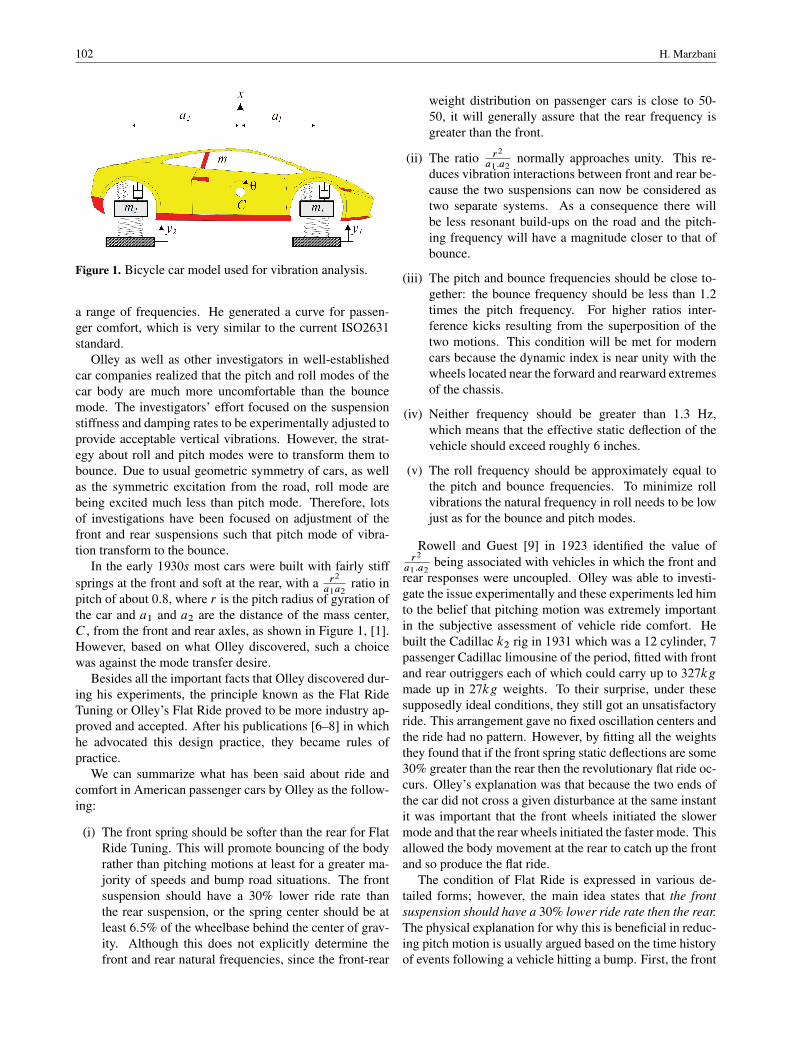
Figure 1. Bicycle car model used for vibration analysis.
a range of frequencies. He generated a curve for passen-ger comfort, which is very similar to the current ISO2631standard.
Olley as well as other investigators in well-establishedcar companies realized that the pitch and roll modes of thecar body are much more uncomfortable than the bouncemode. The investigators’ effort focused on the suspensionstiffness and damping rates to be experimentally adjusted toprovide acceptable vertical vibrations. However, the strat-egy about roll and pitch modes were to transform them tobounce. Due to usual geometric symmetry of cars, as wellas the symmetric excitation from the road, roll mode arebeing excited much less than pitch mode. Therefore, lotsof investigations have been focused on adjustment of thefront and rear suspensions such that pitch mode of vibra-tion transform to the bounce.
In the early 1930s most cars were built with fairly stiffsprings at the front and soft at the rear, with a r2
a1a2ratio in
pitch of about 0:8, where r is the pitch radius of gyration ofthe car and a1 and a2 are the distance of the mass center,C , from the front and rear axles, as shown in Figure 1, [1].However, based on what Olley discovered, such a choicewas against the mode transfer desire.
Besides all the important facts that Olley discovered dur-ing his experiments, the principle known as the Flat RideTuning or Olley’s Flat Ride proved to be more industry ap-proved and accepted. After his publications [6–8] in whichhe advocated this design practice, they became rules ofpractice.
We can summarize what has been said about ride andcomfort in American passenger cars by Olley as the follow-ing:
(i) The front spring should be softer than the rear for FlatRide Tuning. This will promote bouncing of the bodyrather than pitching motions at least for a greater ma-jority of speeds and bump road situations. The frontsuspension should have a 30% lower ride rate thanthe rear suspension, or the spring center should be atleast 6:5% of the wheelbase behind the center of grav-ity. Although this does not explicitly determine thefront and rear natural frequencies, since the front-rear
weight distribution on passenger cars is close to 50-50, it will generally assure that the rear frequency isgreater than the front.
(ii) The ratio r2
a1:a2normally approaches unity. This re-
duces vibration interactions between front and rear be-cause the two suspensions can now be considered astwo separate systems. As a consequence there willbe less resonant build-ups on the road and the pitch-ing frequency will have a magnitude closer to that ofbounce.
(iii) The pitch and bounce frequencies should be close to-gether: the bounce frequency should be less than 1:2times the pitch frequency. For higher ratios inter-ference kicks resulting from the superposition of thetwo motions. This condition will be met for moderncars because the dynamic index is near unity with thewheels located near the forward and rearward extremesof the chassis.
(iv) Neither frequency should be greater than 1:3 Hz,which means that the effective static deflection of thevehicle should exceed roughly 6 inches.
(v) The roll frequency should be approximately equal tothe pitch and bounce frequencies. To minimize rollvibrations the natural frequency in roll needs to be lowjust as for the bounce and pitch modes.
Rowell and Guest [9] in 1923 identified the value ofr2
a1:a2being associated with vehicles in which the front and
rear responses were uncoupled. Olley was able to investi-gate the issue experimentally and these experiments led himto the belief that pitching motion was extremely importantin the subjective assessment of vehicle ride comfort. Hebuilt the Cadillac k2 rig in 1931 which was a 12 cylinder, 7passenger Cadillac limousine of the period, fitted with frontand rear outriggers each of which could carry up to 327kgmade up in 27kg weights. To their surprise, under thesesupposedly ideal conditions, they still got an unsatisfactoryride. This arrangement gave no fixed oscillation centers andthe ride had no pattern. However, by fitting all the weightsthey found that if the front spring static deflections are some30% greater than the rear then the revolutionary flat ride oc-curs. Olley’s explanation was that because the two ends ofthe car did not cross a given disturbance at the same instantit was important that the front wheels initiated the slowermode and that the rear wheels initiated the faster mode. Thisallowed the body movement at the rear to catch up the frontand so produce the flat ride.
The condition of Flat Ride is expressed in various de-tailed forms; however, the main idea states that the frontsuspension should have a 30% lower ride rate then the rear.The physical explanation for why this is beneficial in reduc-ing pitch motion is usually argued based on the time historyof events following a vehicle hitting a bump. First, the front
Flat Ride; Problems and Solutions in Vehicle 103
of the vehicle responds “approximately- in the well-knowndamped oscillation manner. At some time later, controlledby the wheelbase and the vehicle speed, the rear respondsin similar fashion. The net motion of the vehicle is thencrudely some summation of these two motions which mini-mizes the vehicle pitch response, [2].
Confirmation of the effectiveness in pitch reduction ofthe Olley design was given by Best [1] over a limited rangeof circumstances. Random road excitation was applied to ahalf-car computer model, with identical front and rear exci-tations, considering the time delay generated by the wheel-base and vehicle’s speed. Pitch suppression was associatedwith the wheelbase filtering effect. Pitch suppression ap-peared to be necessarily associated with increases in bounceresponse, leaving in unclear whether or not it is a worth-while goal, [10].
Sharp and Pilbeam [11] attempted a more fundamentalinvestigation of the phenomenon, primarily by calculatingfrequency response for the half-car over a wide range ofspeed and design conditions. At higher speeds, remarkablereductions in pitch response with only small costs in termsof bounce response were shown. At low speeds, the situa-tion is reversed. These behavioral features were shown to begeneric insofar as variations in mass center location, pitchinertia and damping level were concerned, and the impli-fications from the frequency responses were confirmed bysimulations with nonlinear asymmetric suspension damp-ing.
Later on Sharp [10] discussed the rear to front stiffnesstuning of the suspension system of a car, through referenceto a half-car pitch plane mathematical model. He used newresults relating to the frequency responses of the bounc-ing and pitching motions of the car body to show that thepitch minimization mechanism of Olley’s Flat Ride tuning“involves interference between the responses to the frontand rear axle inputs. He showed that interference with re-spect to the rotational motion implies reinforcement withrespect to the translational motion, and vice versa. Sharpconclude almost the same facts mentioned by Best and otherresearchers before him, saying that at higher vehicle speeds,Olley tuning is shown to bring advantage in pitch suppres-sion with a very little disadvantage in terms of body accel-eration. At lower speeds, he continues, not only does thepitch tuning bring large vertical acceleration penalties butalso suspension stiffness implied are impractical from anattitude control standpoint.
The flat ride problem was revisited by Crolla andKing [2]. They generated vehicle vibration response spec-tra under random road excitations. Some results includedthe wheelbase filter effect, while others did not. Olley andreverse Olley designs were simulated at speeds of 10, 20,30, and 40 m/s, with the result that Olley design was goodin pitch and bad in bounce in all cases. It was confidentlyconcluded that the rear/front stiffness ratio has virtually noeffect on overall levels of ride comfort.
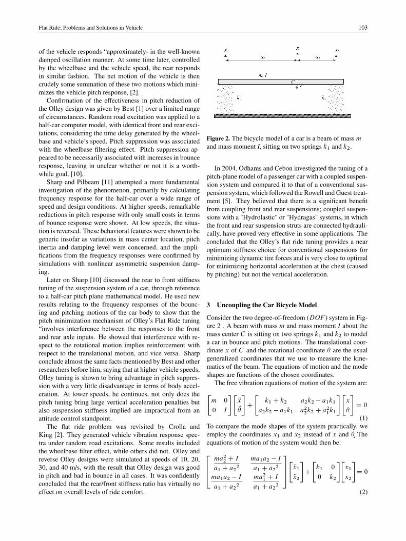
Figure 2. The bicycle model of a car is a beam of mass mand mass moment I, sitting on two springs k1 and k2.
In 2004, Odhams and Cebon investigated the tuning of apitch-plane model of a passenger car with a coupled suspen-sion system and compared it to that of a conventional sus-pension system, which followed the Rowell and Guest treat-ment [5]. They believed that there is a significant benefitfrom coupling front and rear suspensions; coupled suspen-sions with a "Hydrolastic" or "Hydragas" systems, in whichthe front and rear suspension struts are connected hydrauli-cally, have proved very effective in some applications. Theconcluded that the Olley’s flat ride tuning provides a nearoptimum stiffness choice for conventional suspensions forminimizing dynamic tire forces and is very close to optimalfor minimizing horizontal acceleration at the chest (causedby pitching) but not the vertical acceleration.
3 Uncoupling the Car Bicycle Model
Consider the two degree-of-freedom (DOF ) system in Fig-ure 2 . A beam with mass m and mass moment I about themass center C is sitting on two springs k1 and k2 to modela car in bounce and pitch motions. The translational coor-dinate x of C and the rotational coordinate � are the usualgeneralized coordinates that we use to measure the kine-matics of the beam. The equations of motion and the modeshapes are functions of the chosen coordinates.
The free vibration equations of motion of the system are:"m 0
0 I
#"Rx
R�
#C
"k1 C k2 a2k2 � a1k1
a2k2 � a1k1 a22k2 C a21k1
#"x
�
#D 0
(1)To compare the mode shapes of the system practically, weemploy the coordinates x1 and x2 instead of x and �¸ Theequations of motion of the system would then be:2664ma22 C I
a1 C a22ma1a2 � I
a1 C a22
ma1a2 � I
a1 C a22ma21 C I
a1 C a22
3775"Rx1
Rx2
#C
"k1 0
0 k2
#"x1
x2
#D 0
(2)
104 H. Marzbani
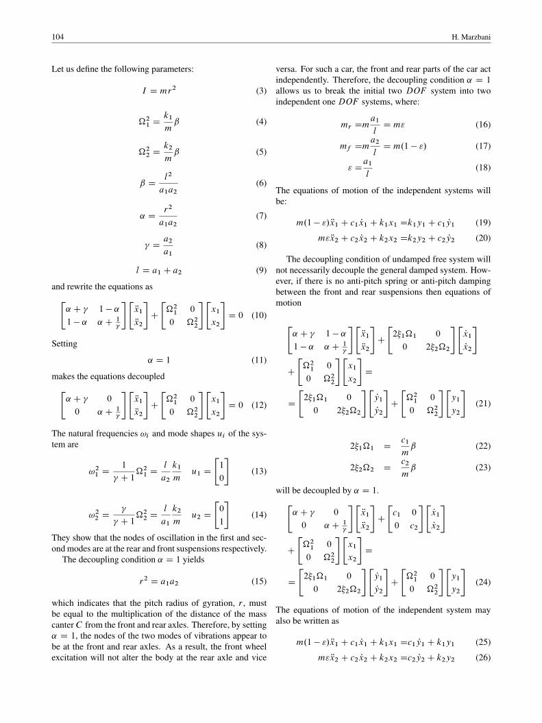
Let us define the following parameters:
I D mr2 (3)
�21 Dk1
mˇ (4)
�22 Dk2
mˇ (5)
ˇ Dl2
a1a2(6)
˛ Dr2
a1a2(7)
Da2
a1(8)
l D a1 C a2 (9)
and rewrite the equations as"˛ C 1 � ˛
1 � ˛ ˛ C 1
#"Rx1
Rx2
#C
"�21 0
0 �22
#"x1
x2
#D 0 (10)
Setting
˛ D 1 (11)
makes the equations decoupled"˛ C 0
0 ˛ C 1
#"Rx1
Rx2
#C
"�21 0
0 �22
#"x1
x2
#D 0 (12)
The natural frequencies !i and mode shapes ui of the sys-tem are
!21 D1
C 1�21 D
l
a2
k1
mu1 D
"1
0
#(13)
!22 D
C 1�22 D
l
a1
k2
mu2 D
"0
1
#(14)
They show that the nodes of oscillation in the first and sec-ond modes are at the rear and front suspensions respectively.
The decoupling condition ˛ D 1 yields
r2 D a1a2 (15)
which indicates that the pitch radius of gyration, r , mustbe equal to the multiplication of the distance of the masscanterC from the front and rear axles. Therefore, by setting˛ D 1, the nodes of the two modes of vibrations appear tobe at the front and rear axles. As a result, the front wheelexcitation will not alter the body at the rear axle and vice
versa. For such a car, the front and rear parts of the car actindependently. Therefore, the decoupling condition ˛ D 1
allows us to break the initial two DOF system into twoindependent one DOF systems, where:
mr Dma1
lD m" (16)
mf Dma2
lD m.1 � "/ (17)
" Da1
l(18)
The equations of motion of the independent systems willbe:
m.1 � "/ Rx1 C c1 Px1 C k1x1 Dk1y1 C c1 Py1 (19)
m" Rx2 C c2 Px2 C k2x2 Dk2y2 C c2 Py2 (20)
The decoupling condition of undamped free system willnot necessarily decouple the general damped system. How-ever, if there is no anti-pitch spring or anti-pitch dampingbetween the front and rear suspensions then equations ofmotion
"˛ C 1 � ˛
1 � ˛ ˛ C 1
#"Rx1
Rx2
#C
"2�1�1 0
0 2�2�2
#"Px1
Px2
#
C
"�21 0
0 �22
#"x1
x2
#D
D
"2�1�1 0
0 2�2�2
#"Py1
Py2
#C
"�21 0
0 �22
#"y1
y2
#(21)
2�1�1 Dc1
mˇ (22)
2�2�2 Dc2
mˇ (23)
will be decoupled by ˛ D 1."˛ C 0
0 ˛ C 1
#"Rx1
Rx2
#C
"c1 0
0 c2
#"Px1
Px2
#
C
"�21 0
0 �22
#"x1
x2
#D
D
"2�1�1 0
0 2�2�2
#"Py1
Py2
#C
"�21 0
0 �22
#"y1
y2
#(24)
The equations of motion of the independent system mayalso be written as
m.1 � "/ Rx1 C c1 Px1 C k1x1 Dc1 Py1 C k1y1 (25)
m" Rx2 C c2 Px2 C k2x2 Dc2 Py2 C k2y2 (26)

Flat Ride; Problems and Solutions in Vehicle 105
which are consistent with the decoupled equations 36 be-cause of
" D1C
�22(27)
4 No Flat Ride Solution for Linear Suspension
The time lag between the front and rear suspension oscil-lations is a function of the wheelbase, l , and speed of thevehicle, v. Soon after the rear wheels have passed over astep, the vehicle is at the worst condition of pitching. Olleyexperimentally determined a recommendation for the opti-mum frequency ratio of the front and rear ends of cars. Hissuggestion for American cars and roads of 50s was to havethe natural frequency of the front approximately 80% of thatof the rear suspension.
To examine Olley’s experimental recommendation andpossibly make an analytical base for flat ride, let us rewritethe equation of motion (25) and (26) as:
Rx1 C 2�1 Px1 Ck1
m.1 � "/x1 D2�1 Py1 C
k1
m.1 � "/y1 (28)
Rx2 C 2��1 Px2 Ckk1
m"x2 D2��1y2 C
kk1
m"y2 (29)
where,
� D�2
�1Dc1
c2
"
1 � "(30)
k Dk2
k1Dk1
k2
"
1 � "(31)
�1 Dc1
m.1 � "/(32)
�2 Dc2
m"(33)
Parameters k and � are the ratio of the rear/front spring ratesand damping ratios respectively.
The necessity to achieve a flat ride provides that the rearsystem must oscillate faster to catch up with the front sys-tem at a reasonable time. At the time both systems mustbe at the same amplitude and oscillate together afterwards.Therefore, an ideal flat ride happens if the frequency of therear system be higher than the front to catch up with the os-cillation of the front at a certain time and amplitude. Then,the frequency of the rear must reduce to the value of thefront frequency to oscillate in phase with the front. Fur-thermore, the damping ratio of the rear must also changeto keep the same amplitude. Such a dual behavior is notachievable with any linear suspension. Therefore, theoreti-cally, it is impossible to design linear suspensions to providea flat ride, as the linearity of the front and rear suspensionskeep their frequency of oscillation constant.
5 Nonlinear Damper
The force-velocity characteristics of an actual shock ab-sorber can be quite complex. Although we may expressthe complex behavior using an approximate function, ana-lytic calculation can be quite complicated with little designinformation. Furthermore, the representations of the exactshock absorber do not greatly affect the behavior of the sys-tem. The simplest linear viscous damper model is usuallyused for linear analytical calculation
FD D cvD (34)
where c is the damping coefficient of the damper.The bound and rebound forces of the damper are dif-
ferent, in other words the force-velocity characteristics dia-gram is not symmetric. Practically, a shock absorber com-presses much easier than decompression. A reason is thatduring rebound in which the damper extends back, it usesup the stored energy in the spring. A high compressiondamping, prevents to have enough spring compression tocollect enough potential energy. That is why in order to geta more reliable and close to reality response for analysis ondampers, using bilinear dampers is suggested. It is similarto a linear damper but with different coefficients for the twodirections [3].
FD D
´cDEvD ExtensioncDCvD Compression
(35)
where cDE is the damping coefficient when damper is ex-tended and cDC is the damping coefficient when the damperis compressed.
An ideal dual behavior damper is one which does notprovide any damping while being compressed and on theother hand damps the motion while extending.
After using the nonlinear model for the damper, the mo-tion had to be investigated in 3 steps for the front and samefor the rear. Ideally, the unit step moves the ground up inno time and therefore the motion of the system begins wheny D 1 and the suspension is compressed. The first stepis right after the wheel hits the step and the damper startsextending. The second step is when the damper starts thecompression phase, which the damping coefficient wouldbe equal to zero. The third step is when the damper startsextending again. Each of the equations of motion should besolved for the 3 steps separately in order to find the time andamplitude of the third peak of the motion which have beenchosen to be optimal time for the flat ride to happen at.
Figure 3 illustrates the behavior of the car equipped witha nonlinear damper when going over a unit step input.
106 H. Marzbani
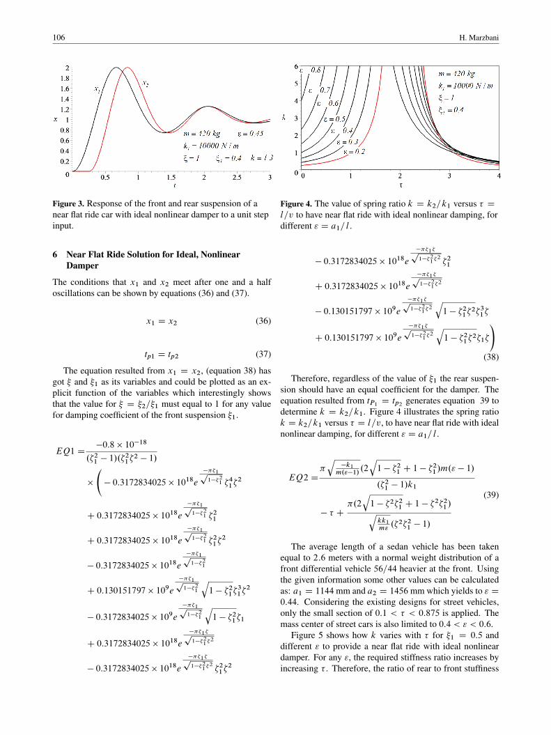
Figure 3. Response of the front and rear suspension of anear flat ride car with ideal nonlinear damper to a unit stepinput.
6 Near Flat Ride Solution for Ideal, NonlinearDamper
The conditions that x1 and x2 meet after one and a halfoscillations can be shown by equations (36) and (37).
x1 D x2 (36)
tp1 D tp2 (37)
The equation resulted from x1 D x2, (equation 38) hasgot � and �1 as its variables and could be plotted as an ex-plicit function of the variables which interestingly showsthat the value for � D �2=�1 must equal to 1 for any valuefor damping coefficient of the front suspension �1.
EQ1 D�0:8 � 10�18
.�21 � 1/.�21�2 � 1/
�
� 0:3172834025 � 1018e
���1p1��2
1 �41�2
C 0:3172834025 � 1018e
���1p1��2
1 �21
C 0:3172834025 � 1018e
���1p1��2
1 �21�2
� 0:3172834025 � 1018e
���1p1��2
1
C 0:130151797 � 109e
���1p1��2
1
q1 � �21�
31�2
� 0:3172834025 � 109e
���1p1��2
1
q1 � �21�1
C 0:3172834025 � 1018e
���1�p1��2
1�2
� 0:3172834025 � 1018e
���1�p1��2
1�2 �21�
2
Figure 4. The value of spring ratio k D k2=k1 versus � Dl=v to have near flat ride with ideal nonlinear damping, fordifferent " D a1=l .
� 0:3172834025 � 1018e
���1�p1��2
1�2 �21
C 0:3172834025 � 1018e
���1�p1��2
1�2
� 0:130151797 � 109e
���1�p1��2
1�2
q1 � �21�
2�31�
C 0:130151797 � 109e
���1�p1��2
1�2
q1 � �21�
2�1�
!(38)
Therefore, regardless of the value of �1 the rear suspen-sion should have an equal coefficient for the damper. Theequation resulted from tP1 D tp2 generates equation 39 todetermine k D k2=k1. Figure 4 illustrates the spring ratiok D k2=k1 versus � D l=v, to have near flat ride with idealnonlinear damping, for different " D a1=l .
EQ2 D�q
�k1m."�1/
.2
q1 � �21 C 1 � �
21/m." � 1/
.�21 � 1/k1
� � C�.2
q1 � �2�21 C 1 � �
2�21/qkk1m".�2�21 � 1/
(39)
The average length of a sedan vehicle has been takenequal to 2:6 meters with a normal weight distribution of afront differential vehicle 56=44 heavier at the front. Usingthe given information some other values can be calculatedas: a1 D 1144mm and a2 D 1456mm which yields to " D0:44. Considering the existing designs for street vehicles,only the small section of 0:1 < � < 0:875 is applied. Themass center of street cars is also limited to 0:4 < " < 0:6.
Figure 5 shows how k varies with � for �1 D 0:5 anddifferent " to provide a near flat ride with ideal nonlineardamper. For any ", the required stiffness ratio increases byincreasing � . Therefore, the ratio of rear to front stuffiness

Flat Ride; Problems and Solutions in Vehicle 107
increases when the speed of the car decreases. Figures 6and 9 also provide the same design graphs for �1 D 0:4,0:3, 0:2, 0:1, respectively.
Figure 5. " versus � , for different k for �1 D 0:5 to havenear flat ride with ideal nonlinear damping.
Figure 6. " versus � , for different k for �1 D 0:4 to havenear flat ride with ideal nonlinear damping.
Figure 7. " versus � , for different k for �1 D 0:3 to havenear flat ride with ideal nonlinear damping.
There will be a possibility of using the � vs. � diagramsas a design chart, which has been illustrated using the valuesin Table 1, by figure 10.
The box in figure 10, is indicating the values that thespring rate should be having as the travelling speed of the
Figure 8. " versus � , for different k for �1 D 0:2 to havenear flat ride with ideal nonlinear damping.
Figure 9. " versus � , for different k for �1 D 0:1 to havenear flat ride with ideal nonlinear damping.
Figure 10. Design chart for a smart suspension with a non-linear damper.
vehicle changes to provide the passengers with a flat ride,in case of having a smart active suspension. The point onthe figure is an example for a passive suspension vehicle. Itis showing the required spring rate, for getting a flat ride ina car with a wheelbase of 2.6 meters, traveling at 28 km/h.

108 H. Marzbani
Table 1. Specification of a sample car.
Specification Nominal value
m Œkg� 420
a1 Œm� 1:4
a2 Œm� 1:47
l Œm� 2:87
k1 ŒN=m� 10000
k2 ŒN=m� 13000
c1 ŒNs=m� 1000
c2 ŒNs=m� 1000
ˇ 4:00238
1:05
�1 95:2947
�2 123:8832
�1 0:05
�2 0:0384
7 ConclusionOlley’s flat ride tuning has been regarded as a rule for de-signing chassis. The fact that these rules were based on ex-perimental results, motivated many researchers to study andvalidate these rules. In this study, has been tried to validateOlley’s results analytically for the first time.
As a result of the dual behavior of the suspension whichis required to get the optimal flat ride, more accurate re-sults were looked for using a nonlinear suspension systemfor this analysis. The results prove that the forward speedof the vehicle affects the flat ride condition, which agreeswith previous researchers’ results. In a passive suspensionsyetem flat ride can be achieved at a certain speed only, sothe suspension system of a car should be designed in a waywhich provides the flat ride at a certain forward speed.
A design chart based on the nonlinear analysis, for smartactive suspension systems has been provided which enablesa car with smart suspension system to provide flat ride atany forward speed of the vehicle. The design chart can
be used for designing chassis with passive suspension fora specified speed as well. examples of both of the abovementioned conditions have been reviewed and discussed,by using some numerical values from a sample car. Theresearch proves the effectiveness of Olley’s flat ride for get-ting a more comfortable ride in cars, and considering theshortcomings of the principles suggests better ways of im-plementing them to the design of suspension systems for abetter and more effective flat ride tuning.
References[1] A. Best, ’Vehicle ride-stages in comprehension’, Physics in
Technology, vol. 15, no. 4, p. 205, 2002.[2] D. Crolla, and R. King, ’Olley’s" Flat Ride" revisited’, 2000.[3] J. Dixon, The shock absorber handbook, Wiley, 2008.[4] W. F. Milliken, D. L. Milliken, and M. Olley, Chassis design,
Professional Engineering Publ., 2002.[5] A. Odhams, and D. Cebon, ’An analysis of ride coupling
in automobile suspensions’, Proceedings of the Institution ofMechanical Engineers, Part D: Journal of Automobile Engi-neering, vol. 220, no. 8, pp. 1041-61, 2006.
[6] M. Olley, ’Independent wheel suspension–its whys andwherefores’, Society of Automotive Engineers Journal, 1934.
[7] M. Olley, ’National influences on American passenger cardesign’, Proceedings of the Institute of Automobile Engi-neers, vol. 32, no. 2, pp. 509-72, 1938.
[8] M. Olley, ’Road manners of the modern car’, Proceedingsof the Institute of Automobile Engineers, vol. 41, no. 1, pp.147-82, 1946.
[9] H. S. Rowell, and J. J. Guest, Proc. Inst. Automobile Engi-neers, 18, PP 455, 1923.
[10] R. Sharp, ’Wheelbase filtering and automobile suspensiontuning for minimizing motions in pitch’, Proceedings of theInstitution of Mechanical Engineers, Part D: Journal of Au-tomobile Engineering, vol. 216, no. 12, pp. 933-46, 2002.
[11] R. Sharp, and C. Pilbeam, ’Achievability and value of pas-sive suspension design for minimum pitch response’, VehicleRide and Handling, vol. 39, pp. 243-59, 1993.
[12] Dai Liming, Reza N. Jazar, Eds., ’Nonlinear Approachesin Engineering Applications’, Springer, New York,Chapter 1: Smart Flat Ride Tuning , Web Address:http://www.springer.com/materials/mechanics/book/978-1-4614-6876-9, 2013.