Finite-Precision Analysis of Demappers and Decoders for LDPC-Coded M-QAM Systems
15
Finite-Precision Analysis of Demappers and Decoders for LDPC-coded M-QAM Systems Marco Baldi, Franco Chiaraluce, Member, IEEE, Giovanni Cancellieri Abstract LDPC codes are state-of-art error correcting codes, included in several standards for broadcast transmissions. Iterative soft- decision decoding algorithms for LDPC codes reach excellent error correction capability; their performance, however, is strongly affected by finite-precision issues in the representation of inner variables. Great attention has been paid, in recent literature, to the topic of quantization for LDPC decoders, but mostly focusing on binary modulations and analyzing finite precision effects in a disaggregrated manner, i.e., considering separately each block of the receiver. Modern telecommunication standards, instead, often adopt high order modulation schemes, e.g. M-QAM, with the aim to achieve large spectral efficiency. This puts additional quantization problems, that have been poorly debated in previous literature. This paper discusses the choice of suitable quantization characteristics for both the decoder messages and the received samples in LDPC-coded systems using M-QAM schemes. The analysis involves also the demapper block, that provides initial likelihood values for the decoder, by relating its quantization strategy with that of the decoder. A new demapper version, based on approximate expressions, is also presented, that introduces a slight deviation from the ideal case but yields a low complexity hardware implementation. Index Terms Demodulation, digital communication, error correction codes, fixed point arithmetic, quantization. I. I NTRODUCTION The current scenario of error correcting codes is dominated by schemes using Soft-Input Soft-Output (SISO) decoding. Among them, an important role is played by Low-Density Parity-Check (LDPC) codes, that permit to approach the theoretical Shannon limit [1], [2], while ensuring reduced complexity. For such reason, these codes have been included in some recent telecommunication standards [3]-[5]. The second generation of Digital Video Broadcasting (DVB) standards, in particular, considers LDPC codes in place of more conventional concatenated schemes formed by Reed-Solomon and convolutional codes, that were adopted in first generation DVB standards. Similarly, the second version of the satellite DVB (DVB-S2) standard includes LDPC codes in conjunction with BCH codes [3]. LDPC codes will be probably adopted also in the upcoming second generation of the terrestrial DVB (DVB-T2) standard, that will replace soon its present version [6]. Possible technologies to be included in such new standard are currently under evaluation [7]. Based on the above considerations, a relevant issue concerns comparison between the error rate performance that is achievable by using LDPC codes and that ensured by other schemes employing SISO decoding. An example of such comparison will be given in Section II for the important case of the Digital Video Broadcasting - Return Channel Satellite (DVB-RCS) standard [8]. Moreover, modern broadcast communications are characterized by increasing throughput requirements; this is true, for example, for the DVB-T2 standard, that must support High Definition Television (HDTV) services. So, there is the need of large spectral efficiencies, that is usually satisfied by employing high order modulation schemes [9], [10]. The DVB-T standard adopts QPSK, 16-QAM and 64-QAM schemes in conjunction with OFDM, and probably the same will be for DVB-T2. Another issue in broadcast transmissions concerns complexity of the decoder implementation, that can be somehow reduced by introducing suitable approximations [11]. In particular, in SISO decoders, complexity is strongly affected by the finite- precision representation of the inner variables. The aim of this paper is to study finite-precision effects on an LDPC coded M -QAM system of the type depicted in Fig. 1; it employs binary LDPC codes in conjunction with high order modulation schemes [12]. The meaning of the various blocks and quantities involved in Fig. 1 will be explained in detail in Sections IV and V. This topic has been already discussed in previous literature, but most of previous works were limited to consider binary modulation. Higher order modulation schemes, like M -QAM, whose adoption is justified by the need to increase the spectral efficiency, put a number of additional problems. In particular, they require to model the effect of the demapper block (i.e., the symbol-to-metric calculator) and to refine the optimization procedure for saving the number of quantization bits without incurring significant performance losses. This can suggest, in particular, the adoption of suitable non-uniform quantization schemes, that are able to face efficiently the clipping effect. If not controlled, this effect can cause the appearance of remarkable and unexpected error floors. Copyright (c) 2008 IEEE. Personal use of this material is permitted. However, permission to use this material for any other purposes must be obtained from the IEEE by sending a request to [email protected]. The authors are with Università Politecnica delle Marche, Ancona, Italy (e-mail: [email protected]; [email protected], [email protected]).
-
Upload
independent -
Category
Documents
-
view
1 -
download
0
Transcript of Finite-Precision Analysis of Demappers and Decoders for LDPC-Coded M-QAM Systems

Finite-Precision Analysis of Demappers andDecoders for LDPC-coded M-QAM Systems
Marco Baldi, Franco Chiaraluce,Member, IEEE, Giovanni Cancellieri
Abstract
LDPC codes are state-of-art error correcting codes, included in several standards for broadcast transmissions. Iterative soft-decision decoding algorithms for LDPC codes reach excellent error correction capability; their performance, however, is stronglyaffected by finite-precision issues in the representation of inner variables. Great attention has been paid, in recent literature, tothe topic of quantization for LDPC decoders, but mostly focusing on binary modulations and analyzing finite precision effectsin a disaggregrated manner, i.e., considering separately each block of the receiver. Modern telecommunication standards, instead,often adopt high order modulation schemes, e.g.M -QAM, with the aim to achieve large spectral efficiency. This puts additionalquantization problems, that have been poorly debated in previous literature. This paper discusses the choice of suitable quantizationcharacteristics for both the decoder messages and the received samples in LDPC-coded systems usingM -QAM schemes. Theanalysis involves also the demapper block, that provides initial likelihood values for the decoder, by relating its quantizationstrategy with that of the decoder. A new demapper version, based on approximate expressions, is also presented, that introducesa slight deviation from the ideal case but yields a low complexity hardware implementation.
Index Terms
Demodulation, digital communication, error correction codes, fixed point arithmetic, quantization.
I. I NTRODUCTION
The current scenario of error correcting codes is dominatedby schemes using Soft-Input Soft-Output (SISO) decoding.Among them, an important role is played by Low-Density Parity-Check (LDPC) codes, that permit to approach the theoreticalShannon limit [1], [2], while ensuring reduced complexity.
For such reason, these codes have been included in some recent telecommunication standards [3]-[5]. The second generationof Digital Video Broadcasting (DVB) standards, in particular, considers LDPC codes in place of more conventional concatenatedschemes formed by Reed-Solomon and convolutional codes, that were adopted in first generation DVB standards. Similarly,the second version of the satellite DVB (DVB-S2) standard includes LDPC codes in conjunction with BCH codes [3]. LDPCcodes will be probably adopted also in the upcoming second generation of the terrestrial DVB (DVB-T2) standard, that willreplace soon its present version [6]. Possible technologies to be included in such new standard are currently under evaluation[7].
Based on the above considerations, a relevant issue concerns comparison between the error rate performance that is achievableby using LDPC codes and that ensured by other schemes employing SISO decoding. An example of such comparison will begiven in Section II for the important case of the Digital Video Broadcasting - Return Channel Satellite (DVB-RCS) standard[8].
Moreover, modern broadcast communications are characterized by increasing throughput requirements; this is true, forexample, for the DVB-T2 standard, that must support High Definition Television (HDTV) services. So, there is the need oflarge spectral efficiencies, that is usually satisfied by employing high order modulation schemes [9], [10]. The DVB-T standardadopts QPSK, 16-QAM and 64-QAM schemes in conjunction with OFDM, and probably the same will be for DVB-T2.
Another issue in broadcast transmissions concerns complexity of the decoder implementation, that can be somehow reducedby introducing suitable approximations [11]. In particular, in SISO decoders, complexity is strongly affected by the finite-precision representation of the inner variables.
The aim of this paper is to study finite-precision effects on an LDPC codedM -QAM system of the type depicted in Fig. 1;it employs binary LDPC codes in conjunction with high order modulation schemes [12]. The meaning of the various blocksand quantities involved in Fig. 1 will be explained in detailin Sections IV and V.
This topic has been already discussed in previous literature, but most of previous works were limited to consider binarymodulation. Higher order modulation schemes, likeM -QAM, whose adoption is justified by the need to increase the spectralefficiency, put a number of additional problems. In particular, they require to model the effect of the demapper block (i.e.,the symbol-to-metric calculator) and to refine the optimization procedure for saving the number of quantization bits withoutincurring significant performance losses. This can suggest, in particular, the adoption of suitable non-uniform quantizationschemes, that are able to face efficiently the clipping effect. If not controlled, this effect can cause the appearance ofremarkableand unexpected error floors.
Copyright (c) 2008 IEEE. Personal use of this material is permitted. However, permission to use this material for any other purposes must be obtainedfrom the IEEE by sending a request to [email protected].
The authors are with Università Politecnica delle Marche, Ancona, Italy (e-mail: [email protected]; [email protected], [email protected]).

1
Source
LDPC
Encoder
Mapper and
Modulator
AWGN
Channel
Demapper
LDPC
Decoder
binary word
binary codeword
QAM signal
intrinsic messages
extrinsic
messages
a posteriori messages
samplesreceived
Detector
Figure 1. Block diagram of the LDPC-codedM -QAM system.
After having derived, through examples, a quantitative evaluation of the quantization and clipping effects for the proposedscenario, we discuss a non-uniform quantization law that represents a good trade-off for both waterfall and error floorperformance. Differently from previous proposals, this non-uniform quantization scheme is specifically targeted to overcomeclipping issues arising inM-QAM systems, while maintaining reasonably small the number of quantization bits. This solutionis obtained through a simple compander-like approach, and can be implemented by exploiting uniform quantization hardware.
We discuss also the relationship that should exist between the number of bits to use in the quantization of the received signalsand the extrinsic messages, in such a way as to ensure comparable quantization errors. This analysis is based on theoreticalarguments on the demapper functions. Finally, we propose a low complexity receiver scheme that, requiring Look-Up Tableswith reduced size, can be convenient in a hardware implementation.
The organization of the paper is as follows. In Section II we present a comparison between the performance of LDPC codesand standard turbo codes for the DVB-RCS application. In Section III we provide a short overview of previous works on thequantization problem, that is the main issue of the paper. InSection IV we describe the system model. In Section V we discussthe choice of the quantization law for the decoder messages.In Section VI we find the relationship that should exist betweenthe input signals quantization and the decoder messages quantization in order to have comparable accuracies. In Section VIIwe develop an approximate analysis of the receiver that permits to express directly the number of quantization bits and,mostof all, can be used to conceive a more efficient implementation. Finally, Section VIII concludes the paper.
II. EXAMPLES OF TURBO-LIKE CODES IN DVB
The introduction of turbo codes has substantially changed the scenario of forward error correction, and started a revisionprocess of traditional coding schemes in practical applications.
Turbo codes are able to achieve very good correction performance, and to approach the Shannon capacity limit. This is dueto the adoption of soft-decision decoding algorithms implementing the so-called "turbo principle", which consists inan iteratedexchange and update of inner messages estimating the reliability of each received bit.
A very similar decoding approach characterizes LDPC codes,first introduced by Gallager [13] and then, recently, rediscoveredby the scientific community. It can be shown that turbo decoding is an instance of Pearl’s "Belief Propagation" algorithm,already implemented in LDPC decoders [14]; so, both turbo and LDPC codes can be included in a wider class of "turbo-like"codes.
Due to their excellent performance, turbo-like codes are being adopted in an increasing number of telecommunicationstandards and applications, with a special focus on DigitalVideo Broadcasting.
The DVB-S2 standard, in particular, makes use of semi-random LDPC codes, characterized by a parity-check matrix obtainedthrough the concatenation of a non-structured block and a staircase lower triangular block (that facilitates systematic encoding).LDPC codes with structured parity-check matrices can reduce both the encoding and decoding complexity; among them, animportant class is represented by Quasi-Cyclic LDPC (QC-LDPC) codes, that can be encoded through very simple circuitsbased on barrel shift registers.
The DVB-RCS standard, that deals with the implementation ofinteractive channels for satellite applications, includes insteada turbo code for error correction. Its turbo encoder uses a double binary circular recursive systematic convolutional code, an

2
optimized two-level interleaver and a puncturing map to deal with variable rates [15]. The information block lengths are alsovariable, ranging from 12 bytes to 216 bytes.
The performance of double binary turbo codes has been compared with that of structured LDPC codes in [16]. The authorsconclude that, for high code length and rate, LDPC codes often outperform turbo codes (they observed that the two schemesachieve comparable performance for rate 3/4 and block length 1152, while, for higher rate and block length, LDPC codes canbe better than turbo codes).
So, it seems interesting to investigate the applicability of structured LDPC codes in those applications where rather longand high-rate codes are needed. As a first example, we have considered the DVB-RCS standard turbo code mentioned above,with MPEG2 information block size (that is 188 bytes [17]) and code rate 4/5.
For comparison, we have simulated two LDPC codes designed with different approaches. Both of them have dimensionk = 1504 and lengthn = 1880, that are coincident with those of the turbo code. The first LDPC code has been designedby means of the Progressive Edge Growth (PEG) algorithm [18], that aims at maximizing the girth length within the Tannergraph. The associated parity-check matrix is non-structured; it has column weight3 and row weight ranging between14 and16.
The second LDPC code is structured and consists of a QC-LDPC code designed through the “Random Difference Families”(RDF) approach [19]. It is characterized by a parity-check matrix formed by a row of5 binary circulant blocks, i.e.,H =[H1, . . . ,H5]. Each block has size376× 376, and row/column weight5, 4, 5, 4 and5, respectively. This implies that matrixH has average column weightdv = 4.6 and row weightdc = 23.
By assuming, without loss of generality, that the blockH5 is non-singular, a very simple systematic form for the generatormatrix of the considered QC-LDPC code is as follows:
G =
I
(
H−15 ·H1
)T
(
H−15 ·H2
)T
(
H−15 ·H3
)T
(
H−15 ·H4
)T
. (1)
where superscripts−1 andT denote inversion and transposition, respectively. MatrixG is formed by a1504× 1504 identitymatrix followed by a column of4 binary circulant blocks (since obtained as the product of circulant blocks). So, the encoderimplementation is very simple, and basically consists in translating the last column of blocks into circuits based on barrel shiftregisters.
With the purpose of extending the comparison to higher rate codes, we have also considered another QC-LDPC code, stilldesigned through the RDF approach, with the same dimension (k = 1504) of the previous one, but rateR = 8/9 (i.e., lengthn = 1692). Its parity-check matrix is a row of nine circulant blocks with size 188 × 188, each having row/column weightequal to 4 or 5. The row weight of the whole matrix isdc = 40, while its average column weight isdv = 4.44.
Looking at the DVB-RCS turbo code, it should be noted that thecode rate8/9 is higher than those considered in thestandard. However, the optimized two-level interleaver can be used also for this rate, while the puncturing rule can be easilyextended, this way giving us the opportunity to make a comparison for a higher rate. Strictly speaking, however, it is quiteevident that this code cannot be considered a standard code;for this reason, we call it "DVB-RCS-like" turbo code with rate8/9.
Figure 2 reports the simulated performance of the considered codes over the AWGN channel, by using BPSK modulationand in absence of quantization. In simulating turbo codes, we have used 8 iterations for rate3/4, and 15 iterations for rate8/9;these choices are adequate for achieving satisfactory convergence of the decoding algorithm. From the figure, we observe thatthe performance of turbo codes and LDPC codes is similar at both rates. The turbo codes exhibit a slightly earlier waterfall,that yields an initial coding gain against LDPC codes, for small signal-to-noise ratio and high error rates. For smallererrorrates, however, the curves of the LDPC codes show a more favorable slope, and intersect those of the turbo codes. Thismeans that, coherent with the conclusions in [16], the LDPC codes can provide a valid alternative to the turbo codes for highsignal-to-noise ratios. If we focus on the FER curve for codes with rate8/9, in particular, an error floor effect appears in theturbo code performance, while the LDPC code has no evident floor, at least in the explored region of FER values.
So, well-designed high-rate LDPC codes are less exposed than turbo codes to floors for error rates of practical interest.Thepresence of error floor in the performance of LDPC codes is even more rare when adopting high order modulations, that arewidely used in modern telecommunication standards. In suchcase, however, “artificial” floors may arise when implementingquantized versions of the LDPC decoder, due to approximation and clipping of intrinsic messages. This motivates our workand, in the following sections, we will study quantization effects for the considered high-rate QC-LDPC code, in conjunctionwith high order modulation schemes.
III. OVERVIEW OF PREVIOUS WORK ON QUANTIZATION
The existence of finite-precision issues in LDPC decoders iswell consolidated: in [20] the “Parity Likelihood Ratio” approach,rather than the more conventional “Log-Likelihood Ratio” (LLR) approach, is proposed to overcome some quantization problems

3
0 1 2 3 4 5 610-8
10-7
10-6
10-5
10-4
10-3
10-2
10-1
BER
Eb/N
0 [dB]
DVB-RCS Turbo 4/5 PEG LDPC 4/5 QC-LDPC 4/5 DVB-RCS-like Turbo 8/9 QC-LDPC 8/9
(a)
0 1 2 3 4 5 610-7
10-6
10-5
10-4
10-3
10-2
10-1
100
FER
Eb/N
0 [dB]
DVB-RCS Turbo 4/5 PEG LDPC 4/5 QC-LDPC 4/5 DVB-RCS-like Turbo 8/9 QC-LDPC 8/9
(b)
Figure 2. Comparison of turbo and LDPC codes for DVB-RCS: (a) Bit Error Rate (BER) and (b) Frame Error Rate (FER) versus the signal-to-noise ratioper bit (Eb/N0).
that appear when the Sum-Product decoding algorithm is applied. In [2] it is clearly stated that adaptive quantization schemes(unfeasible in many practical applications) can exploit better the channel capacity. Besides quantization of decodermessages,in [21] quantization of the received samples is considered,concluding that a 4-bit representation is a good trade-off betweenperformance and complexity. This conclusion, however, is established only for binary (BPSK) modulation, neglecting the impactof the demapper block. On the other hand, in such paper the authors study the decoder structure and propose non-uniformquantization to implement hyperbolic functions.
A similar analysis is developed in [22], where low complexity versions of the logarithmic Sum Product Algorithm (LLR-SPA) are presented. The authors show that core hyperbolic functions of the LLR-SPA decoder can be effectively implementedthrough a uniform quantization or a piece-wise linear approximation, in the latter case with negligible performance loss. Therelevant issue of an optimal trade-off between resolution and dynamic range for decoding non-binary LDPC codes when usedwith BPSK modulation is instead addressed in [23].
Many authors suggest the adoption of 6-bit quantization forthe decoder messages as the best trade-off between performanceand complexity in coded binary modulation [21], [24]-[26].The same choice can be adopted for low-complexity versions ofthe Sum-Product Algorithm, like the Min-Sum variant [27]. But, in this case, it is also proved that less quantization bits inthe implementation of a Min-Sum LDPC decoder can yield a slight performance degradation [28].
When considering higher order modulation schemes, more bitsare necessary to represent both the received samples and thedecoder messages without incurring significant performance loss. Only a few papers are devoted to study such more involvedsituation. An example is in [29], where the authors consideronly uniform quantization schemes. Moreover, quantization isapplied to the decoder messages (with the peculiarities ofM -ary systems), while that of the received samples is neglected.
Even the several proposals of non-uniform quantization schemes are generally addressed to binary systems [30]; on the otherhand a valuable alternative to non-uniform quantization consists in the Soft-Bit decoding approach presented in [31].
The references above evidence the need for deepening the study in the case ofM -ary modulation schemes. An improvedanalysis should take into account the joint effects of the decoder and the demapper blocks. Actually, this is one of the targetsof the present paper, and our proposed solutions will be discussed in the next sections.
IV. SYSTEM MODEL
The analysis we have developed is quite general and can be applied, with some distinctions, to any value ofM . However,for better evidence, in the following we will mainly refer tothe specific case of a 16-QAM constellation. For anyM equal toan even power of 2, a Gray labeling can be adopted to match every sequence oft encoded bits to each symbol. An exampleof Gray labeling forM = 16 is shown in Fig. 3; we will refer to it in the subsequent analysis.
Attention will be focused on the high-rate QC-LDPC code described in Section II. It has lengthn = 1692 and dimensionk = 1504, coincident with the size of an MPEG2 Transport Stream (TS) packet [17]. The code rate isR = 8/9 ≃ 0.9; so, byassumingM = 16, the spectral efficiency is about 3.6 bit/s/Hz, that is a large enough value for most broadcast applications.

4
-4 -3 -2 -1 0 1 2 3 4-4
-3
-2
-1
0
1
2
3
4
0000 0001 00100011
0100 0101 01100111
1000 1001 10101011
1100 1101 11101111
Figure 3. Gray labeling for 16-QAM.
Let us look at Fig. 1. The LDPC encoder maps eachk-bit word produced by the source into ann-bit LDPC codeword.Each codeword is then passed to the mapper and modulator block, that transforms groups oft = log2 M code bits intoa symbol of the bi-dimensionalM -QAM constellation. The modulated signal is then transmitted over an Additive WhiteGaussian Noise (AWGN) channel. At the receiver side, the demapper block is a maximum a posteriori (MAP) symbol-to-bitmetric calculator, that is able to produce an initial likelihood value for each received bit (such values are denoted asintrinsicor channel messages). These messages serve as input for the Sum-Product Algorithm (SPA), that starts iterating and, at eachiteration, produces updated versions of theextrinsicand thea posteriorimessages [32]. The former are used as input for thesubsequent iteration (if needed), while the latter represent the decoder output, and serve to obtain an estimated codeword thatis subject to the hard decision and the parity-check test. The efficiency of this scheme, which is very simple to implement,has been tested even in comparison with more involved solutions, like those based on multilevel coding formats, showingeverywhere excellent error rate performance [12]; therefore, it is often preferred in practical applications.
Simulations have been carried out over the AWGN channel. As the QAM constellation is not geometrically uniform, thesimulated information patterns cannot be fixed (the all zerosequence would be the canonical choice) but are generated byarandom, uncorrelated, source.
V. QUANTIZATION OF DECODERMESSAGES
A. Outline of the Decoding Algorithm
Let x andy be the magnitude of the in-phase and quadrature components,respectively, for each received pass-band signal.The latter, denoted byr = x+ jy, is the sum of a symbols = sx + jsy of the constellation and a sample of a white Gaussiannoisen = nx+ jny, wherenx andny are independent Gaussian random variables with zero mean and varianceσ2. Moreover,let us denote bybk the k-th code bit (k ∈ [1, t]) associated with the symbol, byAk the subset of signals whose label has thevaluebk = 0, and byBk the subset of signals whose label has the valuebk = 1.
The LLR of the coded bitbk, given the received signalr, can be expressed as:
L(bk) = ln
∑
s∈Ake−
‖r−s‖2
2σ2
∑
s∈Bke−
‖r−s‖2
2σ2
= fk(x, y, σ). (2)
The values (2), calculated for all bits of a codeword, are theintrinsic messages given as input to the belief propagationalgorithm. They serve to initializeextrinsicmessages, that are then updated through the iterated exchange of messages betweenvariable and check nodes in the Tanner graph representing the code. At the end of each iteration,a posteriori messages arecalculated and, based on their sign, an estimate of the transmitted codeword is derived. The procedure stops when all theparity-check equations are satisfied or when the maximum number of iterations, fixed a priori, is reached.
The detailed description of the SPA algorithm for LDPC decoding can be found in several books and papers (see [33] and[34], for example) and is here omitted for the sake of brevity.
B. Uniform Midtread Quantization of the Decoder Messages
As stated in the Introduction, in a practical implementation, all the decoder messages are quantized, resulting in a performancedegradation compared to the ideal behavior, that is obtained by assuming real (double precision floating point) variables forthe involved quantities. In principle, we consider uniformmidtread quantization, that converts the real value into a word of m

5
bits. The corresponding law is reported in Eq. (3), whereT is the saturation threshold,d is the quantization step (dependenton the number of bitsm) andx andxuq are the exact and the uniform quantized values, respectively:
xuq = Qu (x,m, T ) =
−T x ≤ −T⌊
xd+ 1
2
⌋
· d −T < x < TT x ≥ T
. (3)
In this expression, “⌊·⌋” represents the floor function, that gives the largest relative number smaller than, or equal to,its argument. When considering uniform midtread quantization, two equivalent approaches are possible: direct fixed pointrepresentation and integer rescaling. In direct fixed pointrepresentation,f bits of each word are reserved for the fractionalpart (this is often denoted as(m : f)) and x is quantized by converting it into its nearest(m : f) value. In this case, thequantization step isd = 2−f and the saturation threshold isT = 2−f
(
2m−1 − 1)
. In the integer rescaling approach, instead,the saturation thresholdT is fixed in advance and the dynamic range±T is divided into(2m − 1) uniform intervals, each withamplituded = T/
(
2m−1 − 1)
. In this case, the value ofxuq can be denoted through them-bit interval indexi =⌊
xd+ 1
2
⌋
it is associated with, or through its fixed point value, coincident with the product of the interval index by the amplituded(whose fixed point representation must be suitably chosen).The set of all the2m − 1 possible values ofxuq can be stored inanm-bit indexed Look-Up Table (LUT) or calculated, any time, through a suitable multiplier circuit.
The integer rescaling approach requires an extra step for reconstructing the quantized values and, depending on the thresholdchoice, can yield a non optimal use of the fixed point representation. However, these drawbacks are overcome when the decoderinvolves only linear operations. For example, the Min-Sum approximate version of the LLR-SPA decoder requires additionsfor variable nodes update, minimum search operations for check nodes update, and sign operations for estimating each bitwhen the decoder stops iterating. In this case, all the quantities involved in the decoding process can be scaled byd, and thewhole decoder can work on integer values, without the need offixed point representation. Furthermore, theintrinsic messagescan be normalized into a fixed range; for example, if the demapper output is divided by its max amplitude (that, in a practicalimplementation, cannot diverge), the input LLRs are normalized into the range[−1;+1]. This way, the dynamic range of thedecoder messages and their quantization threshold become independent of the signal-to-noise ratio. In particular, the choice ofunitary threshold implies clipping of the updated messagesbut not that of initial messages, and this occurs independently ofthe signal-to-noise ratio. For this reason, we adopt the integer rescaling approach.
On the other hand, when using the Min-Sum approximate version of the decoder, the amount of memory required to storethe extrinsic information can be reduced through other strategies ([35], [36]), due to the fact that, at each iteration,extrinsicmessages associated with a check node can assume only two fixed values. This is not the case of the SPA decoder, in whichextrinsic information can assume arbitrary values.
C. Effect of Quantization and Clipping
Because of the inherent complexity of the decoding process,an analytical approach able to express the impact of thequantization/clipping effect would be very difficult to face. Moreover, theoretical arguments permit to obtain only asymptoticresults (n → ∞) [2], that could be quite distant from practical cases. Thus, we resort to numerical simulations.
We consider, for the decoder messages (that isintrinsic, extrinsicanda posteriorimessages), the quantization characteristicof Eq. (3) withm = me andT = Te; the value of such parameters can be optimized through a series of numerical simulations.As regards the threshold, in particular, a preemptive analysis is possible based on theintrinsic messages. If we limit the Gaussplane to a finite square area of side2Ts around the signal constellation, it is possible to calculate, through Eq. (2), the maxintrinsic message amplitude as a function of the average signal-to-noise ratio per bit,Eb/N0, and the bit position. This isshown in Fig. 4 forTs = 4 and the constellation of Fig. 3.
Figure 4 shows that, in the considered range of signal-to-noise ratios, the input LLR can assume very high values. Aswe expect that the clipping effect has a negative impact on the performance of the decoder, according with this figure, thevalue of Te should be set very large. It is interesting to observe that the problem is emphasized by the need to use ratherhigh signal-to-noise ratios because of the adoption of theM -ary modulation. In the case of using BPSK, which is a moreconventional choice, the problem would be much less dramatic. This is because, for a given code and desired error rate, thesignal-to-noise ratios for BPSK are much smaller, and the required value ofTe can be reduced accordingly.
The negative effect of clipping on the initial messages has been confirmed through numerical simulations, whose resultsare reported in Fig. 5. In running simulations, we have adopted the LLR-SPA, with a maximum number of iterations equal to100. The same will be for the other performance curves shown in the sequel. From Fig. 5, we see that the curves of BER andFER corresponding toTe = 7 andme = 4 (i.e., de = 1) show a significant error floor; even if the resolution is increased (forexample, by settingTe = 7 andme = 6, i.e., de = 0.226) the error floor remains. This confirms that the error-floor behavior,in these cases, is mainly due to the effect of clippingintrinsic messages.
On the other hand, if the clipping effect is avoided, for example by increasing the dynamic range though maintaining unitarystep (that happens whenTe = 127 andme = 8 are chosen), the error floor is mitigated (this is evident from the FER curve).Better and better performance can be achieved by increasingalso the quantization resolution: the choice ofTe = 115 andme = 10 (i.e., de = 0.225) ensures, in fact, excellent performance.

6
0 1 2 3 4 5 6 7 8 9 100
10
20
30
40
50
60
70
80
90
Max
Am
pl.
Eb/N0 [dB]
bit 1 and 3 bit 2 and 4
Figure 4. Maxintrinsic message amplitude versusEb/N0 for different bit positions.
7.0 7.2 7.4 7.6 7.8 8.0 8.2 8.4 8.6 8.8 9.0 9.2 9.410-10
10-9
10-8
10-7
10-6
10-5
10-4
10-3
10-2
10-1
BER
Eb/N0
Msg_unq Msg_4-7 Msg_6-7 Msg_8-127 Msg_10-115 Msg_6-115-0.67
(a)
7.0 7.2 7.4 7.6 7.8 8.0 8.2 8.4 8.6 8.8 9.0 9.2 9.410-8
10-7
10-6
10-5
10-4
10-3
10-2
10-1
100
Msg_unq Msg_4-7 Msg_6-7 Msg_8-127 Msg_10-115 Msg_6-115-0.67
FER
Eb/N0
(b)
Figure 5. Performance of the considered LDPC code for uniform(Msg me − Te) and non-uniform (Msgme − Te − F ) midtread decoder messagesquantization: (a) BER versusEb/N0 and (b) FER versusEb/N0.

7
However, the values ofTe and, most of all,me, required to obtain the best performance, when employing the quantizationcharacteristic described by Eq. (3), can become prohibitively high. Therefore, in the next subsection, we introduce a non-uniformquantization characteristic, that is logarithmic in the quantization interval amplitudes.
D. Proposal of a New Non-Uniform Quantization Function
Given the real valuex and a positive real numberF , that we call the logarithmic “factor”, let us definex′ = log (1 + F · |x|),T ′ = log (1 + F · T ) andxs = sign (x). The proposed non-uniform quantization characteristic isas follows:
xnuq = Qnu (x,m, T, F ) =
= xs ·exp(Qu(x′,m,T ′))−1
F
(4)
wherexnuq is the non-uniform quantized version ofx. This new characteristic has more dense quantization levels for smallinput values and more sparse quantization levels for high input values, in line with the observation that nearly zero LLRs(that are responsible for the decoder most uncertain condition) are more sensitive to quantization effects than high LLRs (thatrepresent a firm belief condition).
Non-uniform quantization, according with Eq. (4), is obtained through a classic compander approach based on uniformmidtread quantization. Such a choice, however, implies a more involved hardware realization when (even linear) operationsmust be performed on quantized values; so an accurate complexity assessment must be done when considering this solution.
For Te = 115 andme = 6, the choice ofF = 0.67 implies that the quantization characteristic expressed byEq. (4) hasthe minimum interval amplitude equal todmin
e = 0.225, that coincides with the lowest step already considered foruniformquantization. We have applied the non-uniform quantization with this choice of the parameters and the simulated performanceis also shown in Fig. 5. We see that, by reducing the impact of the clipping effect, the logarithmic characteristic avoidsthepresence of the error floor, even assumingme = 6. More specifically, the BER and FER curves relative to non-uniformquantization withTe = 115 andme = 6 are only a small fraction of dB far from those corresponding to uniform quantizationwith Te = 115 andme = 10, despite the former system adopts a smaller number of quantization bits. In conclusion, law (4),although more involved to implement, seems quite suitable in the region of low error rates.
VI. QUANTIZATION OF THE RECEIVED SIGNALS
The effect of the quantization on the input received samplescan be related, through a simple analytical approach, to thedecoder messages quantization. An estimate of the number ofquantization bits for the input signalsms can be easily found thatis compatible with the resolutionde adopted for the messages, so avoiding introduction of further performance degradation.
A. Estimate of the Maximum Quantization Error
The sub-system processing the received samples should implement Eq. (2): once having obtainedxq andyq, as the results ofan analog-to-digital conversion, these values are used to calculate thefk(xq, yq, σ) for each set of codeword bits (k = 1, ..., 4,in the considered 16-QAM example). Coherent with the approach followed in Section V, the output of the demapper block isthen quantized.
Noting by2Ts the dynamic range of the inputx andy (for example,Ts = 4 in Fig. 3) and byms the number of quantizationbits adopted, under the hypothesis of using uniform midrisequantization (that is preferable, at the input, for a numberof practicalreasons [37]), the quantization step isds = Ts/2
ms−1. The maximum quantization error at the input, forx andy, respectively,is |∆x| = |∆y| = ds/2, and it reflects on a maximum error|∆zk| on the LLR of thek-th bit. Obviously, this propagated errordepends on the value ofms, and a suitable design criterion should consist in choosinganms that satisfies the condition:
|∆zk| ≤de2. (5)
In (5), de represents the constant interval amplitude in the case of uniform LLR quantization, while it can be replaced bythe minimum interval amplitude (dmin
e ) when non-uniform LLR quantization is adopted. If Eq. (5) isverified, the signalquantization has no impact on the decoder messages quantization, and the BER performance is exactly the same achievablewith unquantized input samples.|∆zk| can be approximated through the following expression:
|∆zk| ≈ dzk =
∣
∣
∣
∣
∂fk∂x
dx+∂fk∂y
dy
∣
∣
∣
∣
≈
∣
∣
∣
∣
∂fk∂x
+∂fk∂y
∣
∣
∣
∣
ds2. (6)
8
0 1 2 3 4 5 6 7 8 9 10
6
7
8
9
10
Approximate Bit 1 Exact Bit 2 ExactSi
gnal
Qua
ntiz
atio
n B
itsEb/N0 [dB]
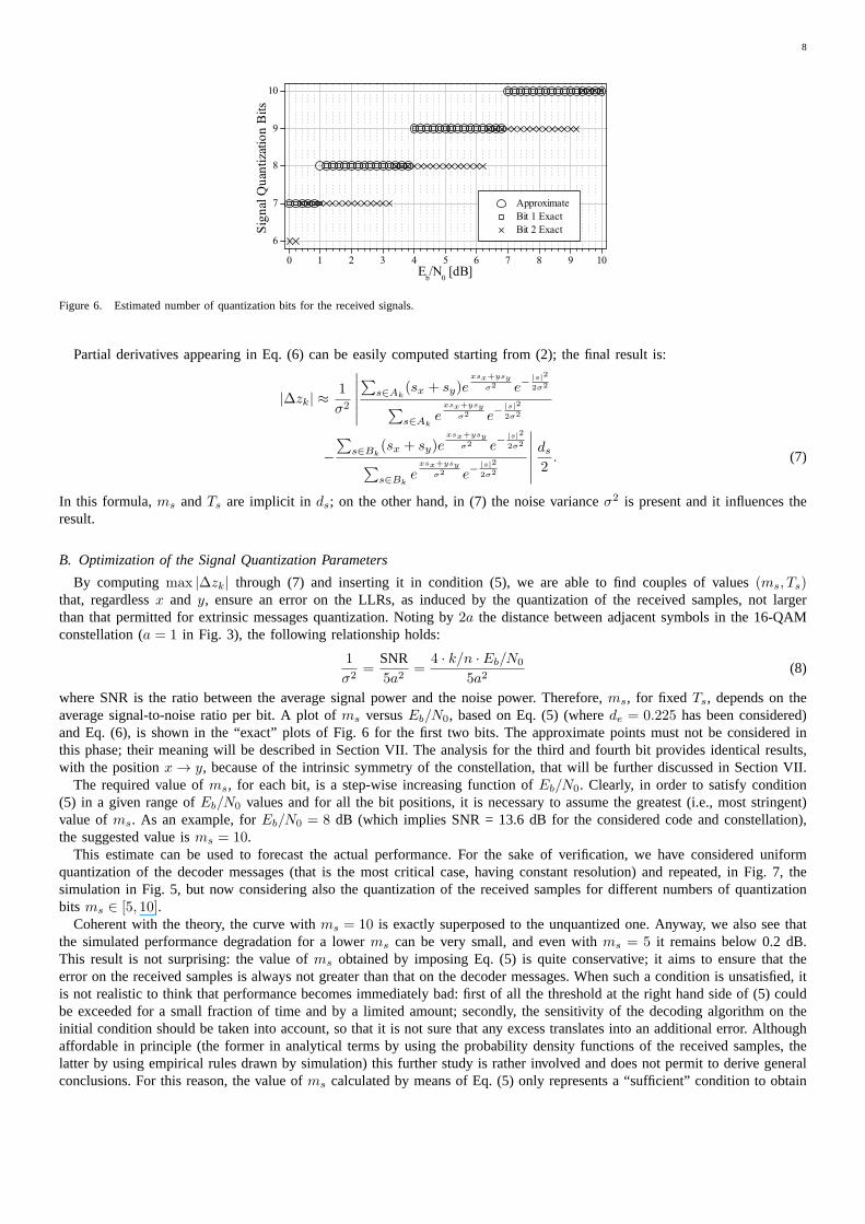
Figure 6. Estimated number of quantization bits for the received signals.
Partial derivatives appearing in Eq. (6) can be easily computed starting from (2); the final result is:
|∆zk| ≈1
σ2
∣
∣
∣
∣
∣
∣
∑
s∈Ak(sx + sy)e
xsx+ysy
σ2 e−|s|2
2σ2
∑
s∈Ake
xsx+ysy
σ2 e−|s|2
2σ2
−
∑
s∈Bk(sx + sy)e
xsx+ysy
σ2 e−|s|2
2σ2
∑
s∈Bke
xsx+ysy
σ2 e−|s|2
2σ2
∣
∣
∣
∣
∣
∣
ds2. (7)
In this formula,ms andTs are implicit in ds; on the other hand, in (7) the noise varianceσ2 is present and it influences theresult.
B. Optimization of the Signal Quantization Parameters
By computingmax |∆zk| through (7) and inserting it in condition (5), we are able to find couples of values(ms, Ts)that, regardlessx and y, ensure an error on the LLRs, as induced by the quantization of the received samples, not largerthan that permitted for extrinsic messages quantization. Noting by 2a the distance between adjacent symbols in the 16-QAMconstellation (a = 1 in Fig. 3), the following relationship holds:
1
σ2=
SNR5a2
=4 · k/n · Eb/N0
5a2(8)
where SNR is the ratio between the average signal power and the noise power. Therefore,ms, for fixed Ts, depends on theaverage signal-to-noise ratio per bit. A plot ofms versusEb/N0, based on Eq. (5) (wherede = 0.225 has been considered)and Eq. (6), is shown in the “exact” plots of Fig. 6 for the firsttwo bits. The approximate points must not be considered inthis phase; their meaning will be described in Section VII. The analysis for the third and fourth bit provides identical results,with the positionx → y, because of the intrinsic symmetry of the constellation, that will be further discussed in Section VII.
The required value ofms, for each bit, is a step-wise increasing function ofEb/N0. Clearly, in order to satisfy condition(5) in a given range ofEb/N0 values and for all the bit positions, it is necessary to assume the greatest (i.e., most stringent)value ofms. As an example, forEb/N0 = 8 dB (which implies SNR = 13.6 dB for the considered code and constellation),the suggested value isms = 10.
This estimate can be used to forecast the actual performance. For the sake of verification, we have considered uniformquantization of the decoder messages (that is the most critical case, having constant resolution) and repeated, in Fig.7, thesimulation in Fig. 5, but now considering also the quantization of the received samples for different numbers of quantizationbits ms ∈ [5, 10].
Coherent with the theory, the curve withms = 10 is exactly superposed to the unquantized one. Anyway, we also see thatthe simulated performance degradation for a lowerms can be very small, and even withms = 5 it remains below 0.2 dB.This result is not surprising: the value ofms obtained by imposing Eq. (5) is quite conservative; it aims to ensure that theerror on the received samples is always not greater than thaton the decoder messages. When such a condition is unsatisfied,itis not realistic to think that performance becomes immediately bad: first of all the threshold at the right hand side of (5)couldbe exceeded for a small fraction of time and by a limited amount; secondly, the sensitivity of the decoding algorithm on theinitial condition should be taken into account, so that it isnot sure that any excess translates into an additional error. Althoughaffordable in principle (the former in analytical terms by using the probability density functions of the received samples, thelatter by using empirical rules drawn by simulation) this further study is rather involved and does not permit to derive generalconclusions. For this reason, the value ofms calculated by means of Eq. (5) only represents a “sufficient”condition to obtain

9
7.0 7.2 7.4 7.6 7.8 8.0 8.2 8.4 8.6 8.8 9.010-9
10-8
10-7
10-6
10-5
10-4
10-3
10-2
10-1
Sig_unq_Msg_10_115 Sig_5_4_Msg_10_115 Sig_6_4_Msg_10_115 Sig_7_4_Msg_10_115 Sig_10_4_Msg_10_115
BER
Eb/N0
(a)
7.0 7.2 7.4 7.6 7.8 8.0 8.2 8.4 8.6 8.8 9.010-6
10-5
10-4
10-3
10-2
10-1
100
Sig_unq_Msg_10_115 Sig_5_4_Msg_10_115 Sig_6_4_Msg_10_115 Sig_7_4_Msg_10_115 Sig_10_4_Msg_10_115
FER
Eb/N0
(b)
Figure 7. Performance of the considered LDPC code for uniformmidrise samples quantization (Sigms − Ts) and uniform midtread decoder messagesquantization (Msgme − Te): (a) BER versusEb/N0 and (b) FER versusEb/N0.
the desired good performance. On the other hand, one can object that such an overestimate (in the specified sense) of the valueof ms obliges to operate with a number of quantization bits unacceptably high. However, it should be noticed that the value ofms only affects the demapper, not the decoder (whose registersare involved in the message passing algorithm), and a simplesolution can be adopted to reduce the complexity of such block. This new proposal is described in the following section.
VII. D EMAPPER BASED ONAPPROXIMATE EXPRESSIONS
A. Second Order Approximation
When the value of SNR (and then ofEb/N0) is sufficiently high, Eq. (7) can be greatly simplified by considering, in eachsum, the leading term only. This dominant contribution is due to the signalss0 = s0x+ js0y ∈ Ak ands1 = s1x+ js1y ∈ Bk that,for eachk, are at minimum distance from the received sampler. This technique coincides with the log-sum approximationand has been successfully applied for both product codes [38] and convolutional codes [39].
Actually, by imposing this simplification and taking into account Eq. (8), Eq. (7) becomes:
|∆zk| ≈SNR5a2
∣
∣(s0x − s1x) + (s0y − s1y)∣
∣
ds2. (9)
This relationship is very simple and more expressive than (7): first of all we notice a linear dependence on the SNR (sucha dependence is necessarily more involved in the rigorous expression). Moreover, in general, it can be further simplified. Forexample, looking at the 16-QAM constellation in Fig. 3, it iseasy to see thats0 ands1 have always in common the in-phasecomponent (i.e.,s0x = s1x) or the quadrature component (i.e.,s0y = s1y) and that the maximum difference between the unequalcomponents is4a. By replacing (9) in (5), together with the highlighted maximum value, with simple algebra we find:
ms ≥
⌈
log2SNR· Ts
5ade
⌉
+ 3 (10)
where⌈x⌉ is the smallest integer greater thanx.

10
-4 -3 -2 -1 0 1 2 3 4-10
-8
-6
-4
-2
0
2
4
6
8
10
Log-
Like
lihoo
d Ra
tio
In-Phase
bit 1 exact bit 1 approx bit 2 exact bit 2 approx
Figure 8. Comparison between the exact and approximate LLRs for the first two bits, as a function ofx (fixed y), at Eb/N0 = 0 dB.
This result is shown in the “approximate” plot of Fig. 6, as a function ofEb/N0, and compared to the exact one (for bits1 and 2). Both the exact and approximate curves exhibit, as obvious, a staircase behavior. Small regions usually exist, forlow/medium signal-to-noise ratios, where the approximateformula can provide a value ofms one bit higher than that givenby the exact formula. Actually, these regions are practically indistinguishable, in theEb/N0 range considered, for the firstbit, whilst they are evident for the second bit. This is due tothe fact that, when the second bit is considered, the maximumdifference between the dominant contributions in|∆z2| is smaller than4a. So, in principle, an adaptive quantization can beconceived, that varies the value ofms according with the bit position. Anyway, it is clear that such a procedure would bedifficult to manage in a practical implementation.
The same simplification used in (9) can be also introduced in the LLR expression (2). This looks like the classic max-logapproximation. Under the same hypotheses, Eq. (2) becomes:
L(bk) ≈ L′(bk) =
= SNR(x−s1x)
2+(y−s1y)2−(x−s0x)
2−(y−s0y)
2
10a2 == f ′
k(x, y, σ).
(11)
The residual difference betweenL(bk) andL′(bk), that is due to the approximation, is appreciable for small signal-to-noiseratios. An example is shown in Fig. 8, forEb/N0 = 0 dB, whereL(b1) and L(b2) are plotted as a function ofx, for anarbitrary y. The difference becomes smaller and smaller for increasingsignal-to-noise ratios and, at the values ofEb/N0 ofinterest (i.e., those required to have low error rates), it is usually acceptable for all bits. An example is shown in Fig.9 forEb/N0 = 8 dB; in this case the exact and approximate curves are almost overlaid. In comparison with Fig. 8, it is interestingto observe the very different LLR’s dynamics.
B. Simplified Demapper
The acceptability of the approximation suggests a simple solution to reduce considerably the complexity of the demapperblock. The exact expression forL(bk), in fact, requires the implementation of a processor able tocalculatefk(x, y, σ), givenits inputs. An alternative solution would be to store the values offk(x, y, σ) in a LUT indexed onxq, yq, σq (i.e. the quantizedversions ofx, y, σ, respectively).
Looking at Eq. (11), instead, a smarter solution is possible. Due to the linearity in the SNR, theme-bit level indexes forthe quantized version offk(x, y) = (x − s1x)
2 + (y − s1y)2 − (x − s0x)
2 − (y − s0y)2 can be stored in the LUT, in place of
those ofL′(bk). This way, the dependence on the SNR is eliminated, and theme-bit output words only depend on thems-bitinput words, regardless of the channel. To reconstruct the value ofL′(bk) from eachme-bit value, if needed, the circuit shownin Fig. 10 can be adopted. It multiplies each level index by the fixed point representation ofSNR/
(
10a2)
. This circuit usesan SNR value that is continuously estimated at the receiver side, for example by using the signal-mean square error (S/MSE)ratio. When multiplication is performed, it is easy to show that, if l is the number of bits used to represent (the always positivequantity) SNR/
(
10a2)
and theme-bit index includes one sign bit, the output value ofL′(bk) can be represented throughm′ = me + l bits, at the most. However, as stated in Section V, when the decoder involves only linear operations, it can be

11
-4 -3 -2 -1 0 1 2 3 4-60
-40
-20
0
20
40
60
Log-
Like
lihoo
d Ra
tio
In-Phase
bit 1 exact bit 1 approx bit 2 exact bit 2 approx
Figure 9. Comparison between the exact and approximate LLRs for the first two bits, as a function ofx (fixed y), at Eb/N0 = 8 dB.
LUT
16-QAM
A/D
A/D
x
y
ms
m’me
bit2
bit1
bit3
bit4
x
x
x
x
SNR/(10a2)
S/MSE
me
me
me
m’
m’
m’
qx
qy
qx
qy
l
ms
( )1 1 , ,z f x y s¢=
( )2 2 , ,z f x y s¢=
( )3 3 , ,z f x y s¢=
( )4 4 , ,z f x y s¢=
Figure 10. Circuit for the evaluation ofL′(bk).
normalized in such a way as to be independent of the signal-to-noise ratio. In this case the demapper does not perform themultiplication step and the LUT output is the initial extrinsic message. The proposed solution permits to implement only oneLUT that contains the quantized values ofL′(bk) and has2ms-bit addresses,ms being the greatest value obtained by applyingthe analysis shown in the previous section to the consideredSNR range.
C. Reduction of the LUTs size
The LUT size isSiM = 22ms · t ·me (12)
i.e., it consists ofSi16 = 22ms · 4 · me bits in the 16-QAM case. This value can be further reduced taking into account the
following considerations.Fig. 11 shows the subsetsAk andBk for the 16-QAM constellation of Fig. 3, calculated for all the bit positionsk = 1 . . . 4.
From Figs. 11(a) and 11(b), we notice that the values off1(x, y) andf2(x, y) depend only on the quadrature component, asin their expressions we have(x− s1x) = (x− s0x). Similarly, from Figs. 11(c) and 11(d), it is evident thatf3(x, y) andf4(x, y)depend only on the in-phase component, as in their expressions we have(y − s1y) = (y − s0y). Moreover, we notice that thetwo subsetsA3 andB3 coincide withA1 andB1, respectively, when an axial symmetry around the bisector of the first andthird quadrant is applied. Therefore, the values off3(x, y) coincide with those off1(x, y), for y = x. Similarly, A4 andB4
coincide withA2 andB2 under the same transformation, so the values off4(x, y) coincide with those off2(x, y), for y = x.Therefore, the same LUT can be used to obtain the values off1(x, y) andf3(x, y), such as those off2(x, y) andf4(x, y).
Hence, the address word length can be halved simply by addingan “input selector” block before the LUT, that is able to

12
-4 -3 -2 -1 0 1 2 3 4-4
-3
-2
-1
0
1
2
3
4
0000 0001 00100011
0100 0101 01100111
1000 1001 10101011
1100 1101 11101111
(a)
-4 -3 -2 -1 0 1 2 3 4-4
-3
-2
-1
0
1
2
3
4
0000 0001 00100011
0100 0101 01100111
1000 1001 10101011
1100 1101 11101111
(b)
-4 -3 -2 -1 0 1 2 3 4-4
-3
-2
-1
0
1
2
3
4
0000 0001 00100011
0100 0101 01100111
1000 1001 10101011
1100 1101 11101111
(c)
-4 -3 -2 -1 0 1 2 3 4-4
-3
-2
-1
0
1
2
3
4
0000 0001 00100011
0100 0101 01100111
1000 1001 10101011
1100 1101 11101111
(d)
Figure 11. SubsetsAk (diamond markers) andBk (square markers) for the 16-QAM constellation of Fig. 3: (a)A1 andB1, (b) A2 andB2, (c) A3 andB3 and (d)A4 andB4.
forward only the right component of each input signal on the basis of the bit position. The corresponding circuit is plotted inFig. 12.
In this case, only the values off1(x, y) andf2(x, y) are stored in the LUT. As previously shown, such values only dependon y (therefore they can be calculated for an arbitrary value ofx) and coincide with those off3(x, y) andf4(x, y) for y = x.Hence, when the switch in Fig. 12 is in position “A”, the quadrature component of the input signal is used as index for theLUT, and the values off1(x, y) andf2(x, y) are available at its outputs. On the contrary, when the switch is in position “B”,the in-phase component of the input signal is used as index, and the values off3(x, y) andf4(x, y) are available at the twooutputs. Hence, the LUT shown in Fig. 12 consists ofS16 = 2ms · 2 ·me bits, and it is2ms+1 times smaller than that in Fig.10.
The same arguments hold for any Gray-labeled constellationof M = 2t signals, witht even. In all these cases, the demapperblock can be implemented by means of a LUT withms-bit addresses andt/2 me-bit outputs, that is, with size
SM = 2ms ·t
2·me. (13)
However, it should be noted that, for demapping each received sample, the circuit in Fig. 12 requires two LUT accesses,while that in Fig. 10 requires only one access. Therefore, two optimized circuits should be used in order to obtain the samelatency as for the original scheme. Nevertheless, if we consider two implementations of the optimized circuit and comparetheir size with that of the original one, we obtain a size gainGS equal to
GS =SiM
2SM
= 2ms . (14)
The value ofGS depends on the number of quantization bits used for the received samples,ms, as expected. As shownin the previous sections, this number can be quite high (up to10), thus yielding a considerable size gain when adopting the

13
LUT
16-QAMms
me
msme
( ) ( )2 4, / ,f y f x× ×
( ) ( )1 3, / ,f y f x× ×
ms
A
Bqx
qy
Input Select
Figure 12. Circuit employing the 16-QAM demapper LUT with reduced size.
optimized circuit.
VIII. C ONCLUSION
Modern telecommunications require more and more reliable and spectrally efficient transmissions. Reliability can be achievedby using LDPC codes, while spectral efficiency requires the adoption of high order modulation, likeM -QAM, schemes. Practicalimplementation of these solutions needs to reconsider manyof the conclusions already drawn for the more classic LDPC codedbinary modulations. The larger signal-to-noise ratio required, as a counterpart to the improved spectral efficiency, makes theM -ary modulated scheme much more sensitive to the clipping effect, to the point that unexpected error floors can appear ifthe system parameters are not correctly designed. In principle, the number of quantization bits needed can become very large,thus making the system quite unfeasible. To solve the problem, attractive solutions seem to be the adoption of non-uniformquantization and in deep analysis of the demapper block functionalities. By exploiting symmetry properties and takingintoaccount the peculiarities of the quantities involved in thedecision process, efficient demapping can be achieved with minimumsize LUTs. The role of the quantization of the incoming signals can be also controlled in such a way as to avoid altering thetrade-off found in the quantization of the decoder messages.
We have studied these aspects for the case of DVB compatible LDPC codes, in conjunction withM -QAM modulation. Forthe sake of clarity, the results presented in this paper havebeen referred to the specific case of 16-QAM, but most of theanalysis and the proposed new ideas can be easily extended tohigher order constellations and, in principle, toM -ary systemswith different modulations.
ACKNOWLEDGMENT
The authors wish to thank Giambattista Di Donna and Sergio Bianchi, at Siemens, for their contribution and helpfuldiscussion.
REFERENCES
[1] D. MacKay and R. Neal, “Near Shannon limit performance of low density parity check codes,”Electronics Letters, vol. 33, no. 6, pp. 457–458, Mar.1997.
[2] T. Richardson and R. Urbanke, “The capacity of low-density parity-check codes under message-passing decoding,”IEEE Trans. Inform. Theory, vol. 47,no. 2, pp. 599–618, Feb. 2001.
[3] Digital Video Broadcasting (DVB); Second Generation Framing Structure, Channel Coding and Modulation Systems for Broadcasting, InteractiveServices, News Gathering and Other Broadband Satellite Applications, ETSI EN Std. 302 307 (v1.1.2), Rev. 1.1.1, Jun. 2006.
[4] IEEE P802.11 Wireless LANs WWiSE Proposal: High throughputextension to the 802.11 Standard, IEEE Std. 11-04-0886-00-000n, Aug. 2004.[5] IEEE Standard for Local and Metropolitan Area Networks - Part 16: Air Interface for Fixed and Mobile Broadband Wireless Access Systems - Amendment
for Physical and Medium Access Control Layers for Combined Fixed and Mobile Operation in Licensed Bands, IEEE Std. 802.16e-2005, Dec. 2005.[6] Digital Video Broadcasting (DVB); Framing structure, channel coding and modulation for digital terrestrial television, ETSI EN Std. 300 744 (v1.5.1),
Nov. 2004.[7] “DVB-T2 call for technologies,” Digital Video Broadcasting Project, Tech. Rep. SB 1644r1, Apr. 2007.[8] Digital Video Broadcasting (DVB); Interaction channel forsatellite distribution systems, ETSI EN Std. 301 790 (v1.4.1), Sep. 2005.[9] N. H. Tran and H. H. Nguyen, “Signal mappings of 8-ary constellations for bit interleaved coded modulation with iterative decoding,”IEEE Trans.
Broadcast., vol. 52, no. 1, pp. 92–99, Mar. 2006.[10] B. Rong, T. Jiang, X. Li, and M. R. Soleymani, “Combine LDPCcodes over GF(q) with q-ary modulations for bandwidth efficient transmission,”IEEE
Trans. Broadcast., vol. 54, no. 1, pp. 78–84, Mar. 2008.[11] S. Papaharalabos, M. Papaleo, P. T. Mathiopoulos, M. Neri, A. Vanelli-Coralli, and G. E. Corazza, “DVB-S2 LDPC decoding using robust check node
update approximations,”IEEE Trans. Broadcast., vol. 54, no. 1, pp. 120–126, Mar. 2008.[12] Y. Li and W. Ryan, “Bit-reliability mapping in LDPC-coded modulation systems,”IEEE Commun. Lett., vol. 9, no. 1, pp. 1–3, Jan. 2005.[13] R. G. Gallager, “Low-density parity-check codes,”IRE Trans. Inform. Theory, vol. IT-8, pp. 21–28, Jan. 1962.[14] R. J. McEliece, D. J. C. MacKay, and J.-F. Cheng, “Turbo decoding as an instance of Pearl’s "belief propagation" algorithm,” IEEE J. Select. Areas
Commun., vol. 16, no. 2, pp. 140–152, Feb. 1998.[15] C. Douillard, M. Jézéquel, C. Berrou, N. Brengarth, J. Tousch, and N. Pham, “The turbo code standard for DVB-RCS,” inProc. Second International
Symposium on Turbo Codes, Brest, France, Sep. 2000, pp. 535–538.[16] T. Lestable, E. Zimmerman, M.-H. Hamon, and S. Stiglmayr, “Block-LDPC codes vs duo-binary turbo-codes for european nextgeneration wireless
systems,” inProc. IEEE VTC-2006 Fall, Montréal, Canada, Sep. 2006, pp. 1–5.[17] Information technology - Generic coding of moving picturesand associated audio information - Part 1: System, ISO/IEC Std. 13 818-1, 1996.[18] X. Y. Hu and E. Eleftheriou, “Progressive edge-growth Tanner graphs,” inProc. IEEE Global Telecommunications Conference (GLOBECOM’01), vol. 2,
San Antonio, TX, Nov. 2001, pp. 995–1001.

14
[19] M. Baldi and F. Chiaraluce, “Cryptanalysis of a new instance of McEliece cryptosystem based on QC-LDPC codes,” inProc. IEEE ISIT 2007, Nice,France, Jun. 2007, pp. 2591–2595.
[20] L. Ping and W. Leung, “Decoding low density parity checkcodes with finite quantization bits,”IEEE Commun. Lett., vol. 4, no. 2, pp. 62–64, Feb.2000.
[21] T. Zhang, Z. Wang, and K. Parhi, “On finite precision implementation of low density parity check codes decoder,” inIEEE International Symposium onCircuits and Systems ISCAS 2001, vol. 4, Sydney, NSW, May 2001, pp. 202–205.
[22] X.-Y. Hu, E. Eleftheriou, D.-M. Arnold, and A. Dholakia, “Efficient implementations of the sum-product algorithm for decoding LDPC codes,” inProc.IEEE Global Telecommunications Conference (GLOBECOM’01), vol. 2, San Antonio, TX, Nov. 2001, pp. 1036–1036E.
[23] H. Wymeersch, H. Steendam, and M. Moeneclaey, “Computational complexity and quantization effects of decoding algorithms for non-binary LDPCcodes,” inProc. IEEE Int. Conf. on Acoustic, Speech and Signal Processing, ICASSP 2004, vol. 4, Montreal, Canada, May 2004, pp. 669–672.
[24] S. Kim, G. Sobelman, and J. Moon, “Parallel VLSI architectures for a class of LDPC codes,” inProc. IEEE ISCAS 2002, vol. 2, Scottsdale, AZ, May2002, pp. II–93–II–96.
[25] S. L. Howard, C. Schlegel, and V. C. Gaudet, “Degree-matched check node decoding for regular and irregular LDPCs,”IEEE Trans. Circuits Syst. II,vol. 53, no. 10, pp. 1054–1058, Oct. 2006.
[26] L. Yang, H. Liu, and C.-J. Richard Shi, “Code construction and FPGA implementation of a low-error-floor multi-rate low-density parity-check codedecoder,”IEEE Trans. Circuits Syst. I, vol. 53, no. 4, pp. 892–904, Apr. 2006.
[27] D. Oh and K. K. Parhi, “Performance of quantized min-sum decoding algorithms for irregular LDPC codes,” inProc. IEEE ISCAS 2007, New Orleans,LA, May 2007, pp. 2758–2761.
[28] Z. Cui and Z. Wang, “Efficient message passing architecture for high throughput LDPC decoder,” inProc. IEEE ISCAS 2007, New Orleans, LA, May2007, pp. 917–920.
[29] M. Shen, H. Niu, H. Liu, and J. Ritcey, “Finite precisionimplementation of LDPC coded M-ary modulation over wireless channels,” inProc. AsilomarConference on Signals, Systems and Computers, vol. 1, Nov. 2003, pp. 114–118.
[30] Z. Cui and Z. Wang, “A 170 Mbps (8176, 7156) quasi-cyclicLDPC decoder implementation with FPGA,” inProc. IEEE ISCAS 2006, Kos, Greece,May 2006, pp. 5095–5098.
[31] S. Howard, V. Gaudet, and C. Schlegel, “Soft-bit decoding of regular low-density parity-check codes,”IEEE Trans. Circuits Syst. II, vol. 52, no. 10, pp.646–650, Oct. 2005.
[32] J. Hagenauer, E. Offer, and L. Papke, “Iterative decoding of binary block and convolutional codes,”IEEE Trans. Inform. Theory, vol. 42, no. 2, pp.429–445, Mar. 1996.
[33] S. Lin and D. J. Costello,Error Control Coding, Second Edition. Upper Saddle River, NJ, USA: Prentice-Hall, Inc., 2004.[34] D. J. C. MacKay, “Good error correcting codes based on very sparse matrices,”IEEE Trans. Inform. Theory, vol. 45, no. 2, pp. 399–432, Mar. 1999.[35] A. Hunt, “Hyper-codes: High-performance low-complexity error-correcting codes,” Master’s thesis, Carleton University, Ottawa, Canada, 1998.[36] A. Hunt, J. Lodge, and S. Crozier, “Method of enhanced max-log-a posteriori probability processing,” U.S. Patent 6145114, Nov. 2000.[37] Siemens, private communication, Cassina de’ Pecchi, Italy, Apr. 2006.[38] R. Pyndiah, A. Picart, and A. Glavieux, “Performance of block turbo coded 16-QAM and 64-QAM modulations,” inProc. IEEE Global Telecommuni-
cations Conference (GLOBECOM’95), vol. 2, Singapore, Nov. 1995, pp. 1039–1043.[39] F. Tosato and P. Bisaglia, “Simplified soft-output demapper for binary interleaved COFDM with application to HIPERLAN/2,” in Proc. IEEE ICC 2002,
vol. 2, New York, May 2002, pp. 664–668.