Finite-size scaling for quantum criticality using the finite-element method
Upload
khangminh22Category
view
0download
0
�����������������
Citation: Al-Fakih, A.; Al-Osta, M.A.
Finite Element Analysis of
Rubberized Concrete Interlocking
Masonry under Vertical Loading.
Materials 2022, 15, 2858. https://
doi.org/10.3390/ma15082858
Academic Editors: Jacopo Donnini
and Simone Spagnuolo
Received: 28 March 2022
Accepted: 12 April 2022
Published: 13 April 2022
Publisher’s Note: MDPI stays neutral
with regard to jurisdictional claims in
published maps and institutional affil-
iations.
Copyright: © 2022 by the authors.
Licensee MDPI, Basel, Switzerland.
This article is an open access article
distributed under the terms and
conditions of the Creative Commons
Attribution (CC BY) license (https://
creativecommons.org/licenses/by/
4.0/).
materials
Article
Finite Element Analysis of Rubberized Concrete InterlockingMasonry under Vertical LoadingAmin Al-Fakih 1,* and Mohammed A. Al-Osta 1,2
1 Interdisciplinary Research Center for Construction and Building Materials, King Fahd University ofPetroleum and Minerals, Dhahran 31261, Saudi Arabia; [email protected]
2 Department of Civil and Environmental Engineering, King Fahd University of Petroleum and Minerals,Dhahran 31261, Saudi Arabia
* Correspondence: [email protected]; Tel.: +966-531336061
Abstract: Fine aggregate and cement have been partially replaced by 10% and 56% crumb rubber andclass F-fly ash, respectively, in order to manufacture rubberized concrete interlocking bricks (RCIBs).The newly developed product has been used for masonry construction without the need for mortar(mortarless), and the experimental testing under compression load was investigated by Al-Fakih et al.Therefore, in line with that, this study carried out finite element (FE) analysis for experimental resultvalidation of masonry walls and prisms made of RCIBs. ANSYS software was utilized to implementthe FE analysis, and a plasticity detailed micro-modeling approach was adopted. Parametric studieswere carried out on masonry prisms to investigate the effect of the slenderness ratio and the elasticmodulus of grout on the prism behavior. The results found that the adopted FE model has the abilityto predict the structural response, such as compressive strength, stiffness, and failure mechanism, ofthe interlocking masonry prisms with about a 90% agreement with the experimental results. Basedon the parametric studies, the compressive strength for a 6-course prism is approximately 68% lessthan a 3-course prism and 60% less than a 5-course prism, which means that the slenderness ratioplays a vital role in the behavior of the RCIB masonry prism under the vertical compression load.Moreover, the results showed that the difference between FE and experimental results of the wallswas less than 16%, indicating a good match. The findings also reported that masonry walls andprisms experienced higher ductility measured by the post-failure loading under compression. Thefinite element model can be used for further investigation of masonry systems built with rubberizedconcrete interlocking bricks.
Keywords: crumb rubber; interlocking brick; rubberized concrete; finite element; ANSYS
1. Introduction
Masonry, whether traditional or dry-stacked, has a heterogeneous and discontinuousnature and nonlinear material behavior. This is partly attributed to the interfaces betweenits elements, including the masonry block assembly, the mixture of filler material (mortar),and grout. For mortarless (dry-stacked) masonry, the interface behavior at the dry bed andhead joints are much more complicated due to the inevitable air space in the uncontactedregion (bed or head joints). The stress field is even more complicated throughout thesurrounding continuum [1–3].
Nowadays, computer simulation studies have become an easy and appropriate methodto determine the structural behavior of many civil engineering structures, including con-crete, steel, and masonry. Some of the simulation methods include the extended finiteelement method [4], damage mechanics [5], discrete element methods [6–8], and finite ele-ment methods [9,10]. Nonlinear finite element analysis technologies are the most powerfuland readily available for masonry subjected to quasi-static monotonous loading and aresome of the most advanced structural analysis approaches that take into account various
Materials 2022, 15, 2858. https://doi.org/10.3390/ma15082858 https://www.mdpi.com/journal/materials

Materials 2022, 15, 2858 2 of 17
sources of nonlinearity such as material and geometry [9,10]. Although the interlockingmortarless masonry system is not new, few reported masonry studies using finite elementanalysis have been found, especially focused on this problem. The following numericalstudies were reported, which depend mainly on the type of blocks used to assemble thewalls. Three finite element modeling methodologies for the investigation of masonrystructures were used to simulate the masonry complexity, namely detailed and simplifiedmicro- and macro-modeling. In the detailed micro-modeling method, bricks and mortarare presented by continuum elements, while the interface between the mortar and unitis presented by discontinuous elements. The simplified micro-model is the same as thedetailed micro-model, but the joints and interface elements are re-defined as individualelements to represent a contact area. In contrast, in the macro-modeling approaches, thedistinction between individual units and joints is not made [11–15].
Senthivel and Lourenço [16] carried out a nonlinear finite element analysis to modelthe behavior of stone dry-stacked masonry shear walls under combined loading (axial andlateral). The micro-modeling approach and multi-surface interface model are followed inthis analysis, where bricks and joints are assumed elastic and inelastic, respectively. Theresults showed a good agreement between the finite element and laboratory test results.Martínez and Atamturktur [17,18] validated the experimental results of reinforced dry-stacked concrete masonry walls subjected to out-of-plane loading using finite elementmodels. A perfectly plastic model using the Willam–Warnke criterion is implemented.Concrete masonry units and grout are modeled using the SOLID65 element from theANSYS 15.0 library, while brick-to-brick contact is modeled using surface-to-surface contactelements (CONTA174 and TARGE170 elements). The results showed that an increasein the unit and grout compressive strength enhances the ultimate lateral load-carryingcapacity as well as the ductility of the dry-stacked wall. In general, the numerical andexperimental results corresponded well. Oh [19] developed a finite element model tosimulate the behavior of interlocking mortarless blocks established at Drexel University.The method established to simulate the contact behavior of the dry-stack joint, includinggeometric imperfection of the dry joint, is adequate, mostly for the modeling of smallmasonry assemblies. Material nonlinearity is not known to compensate for masonrybehavior close to the ultimate load and to anticipate the failure mode. In order to modelthe joint and block as a homogenous object, Alpa et al. [20] proposed a macro model thatfollows the homogenization methods. This model focuses on the moving structure of thedry joint, which includes a precise joint. Without adjustment, it is impossible to use themodel for structural implementation because it lacks important problems like gradualfailure of material, nonlinearity of material, and joint imperfections.
Thanoon et al. [21,22] developed an incremental-iterative program that used a planestress 2D continuum finite element approach to anticipate the performance and failuremechanism of an interlocking mortarless system under compression. For interface fail-ure, the Mohr-Coulomb criterion was used, and the behavior of interlocking prisms waspredicted. The experimental and finite element results were found to be in good agree-ment. Shi et al. [23] simulated the interlocking brick prisms using a detailed 3D FE modelin ABAQUS, where the results of the FE modeling were compared to the results of theexperimental findings. The damage and failure patterns of interlocking brick prisms wereshown in both laboratory experiments and numerical simulations. Oliveira et al. [24] con-cluded that the concrete damaged plasticity model, using a micro-modelling approach, wasdemonstrated to be effective for simulating the behavior of dry-stacked walls at ambientand high temperatures. Chewe Ngapeya and Waldmann [25] carried out an experimentaland analytical analysis of the load-bearing capacity of dry-stacked masonry wallets andconcluded that, with a mean accuracy of 93%, the suggested mathematical model couldpredict the loadbearing capacity of dry-stacked masonry.
In addition to the experimental work reported by Ayed et al. [26], and in order toillustrate the effect of local stress on the compressive behavior of masonry, a finite elementtechnique has also been performed. The ABAQUS module interaction is used to model
Materials 2022, 15, 2858 3 of 17
the surface-to-surface contact behavior between the interlocking bricks. The experimentalyield pseudo linear load of compressed interlocking blocks is slightly underestimated bythe linear elastic model with yield tensile stress, according to the findings.
In line with the experimental work by Andreev et al. [27], the effect of joint geometryand material stiffness on the process of joining dry joints in refractory ceramic masonry wasstudied utilizing FEM analysis. The authors used ANSYS software to implement the finiteelement analysis. The elastic-plastic model was adopted, and the results showed that thebrick material with elastic-plastic behavior could obtain joint closure curves similar to theexperimental results with the flattening curve. Moreover, Ngapeya et al. [28] established afinite element method to examine the influence of the geometric imperfections, includingthe height variation of different blocks (∆H) and the roughness of the contact area (∆h),on the structural behavior of the dry-stack masonry walls. The authors modeled thedry-stacked masonry block as a 3-D micro-model with consideration of the crushing andcracking capability by using SOLID65 cubic elements provided by ANSYS 17, while thedry joint was modeled as LINK elements, which ensure a load transfer through the actualcontact areas. Alternatively, the Coulomb friction law governs the behavior of joints indry-stacked masonry [29,30].
Recently, a rubberized concrete interlocking brick has been developed [1,31–33]. It iscategorized as heterogeneous and discontinuous due to the interface between its constituentmaterials, namely, brick unit, dry joint, and grout. Finite element modeling (FEM) wascarried out in this research to simulate the behavior of hollow and grouted rubberizedconcrete interlocking masonry prism and hollow wall under axial compressive loadinguntil failure in order to validate the experimental results obtained by Al-Fakih et al. [1].
2. Materials and Models
Fine aggregates, cement, crumb rubber, fly ash, and water were utilized to makerubberized concrete interlocking brick. Ordinary Portland cement (OPC) has specificgravity and loss of ignition of 3.15% and 2.2%, respectively, confirming the requirementsof ASTM C150 [34]. Class F-fly ash has a specific gravity of 2.38, obtained from a coalfire power plant, and has been partially used to replace cement by volume. The washriver sand has a specific gravity of 2.57 and a maximum particle size of 1.2 mm. Mesh #30(60 microns), nominal size, crumb rubber particles with a specific gravity of 0.95 have beenused to replace sand by volume partially. Moreover, the partial replacement of cement andfine aggregate by fly ash and crumb rubber was 56% and 10%, respectively, by volume. Amix ratio of 1:2 (cementitious materials (OPC and FA) to fine aggregates (sand and CR)) wasadopted with a water to cement ratio of 0.27. The ingredients and chemical composition ofthe components employed have already been detailed in Refs. [1,31,32,35].
2.1. FE Model
Rubberized concrete interlocking masonry categorizes as heterogeneous and discon-tinuous due to the interfaces between its constituent materials, namely, brick unit, dry joint,and grout. The finite element (FE) technique is implemented to simulate the behavior ofboth hollow and grouted rubberized concrete interlocking masonry under axial compres-sive loading until failure. A detailed micro-modeling approach was followed where eachconstituent of rubberized concrete interlocking masonry (brick and dry joint) connectedto each other by surface contacts at their actual position. A nonlinear 3-D finite elementmodel was developed using the commercial FE modeling package (ANSYS R19.1), andthe observed behaviors are validated with the experimental results. Two masonry systemswere modeled, including prisms (hollow and grouted) and walls (hollow). Once this stagewas accomplished, two parametric studies were carried out, namely: (1) effects of modulusof elasticity of grout on the behavior of grouted masonry prism; and (2) effects of thenumber of courses (slenderness ratio) on the strength of both hollow and grouted prismsmade of RCIB.

Materials 2022, 15, 2858 4 of 17
2.2. Geometry and FE Mesh
A compatible 3D FEM geometry of rubberized concrete interlocking masonry prismsand walls was established similar to those tested experimentally. The geometry of thehollow and grouted prisms consists of three courses and two dry joints, as shown inFigure 1a. Alternatively, the size of the hollow wall was chosen to be 625 mm (two and ahalf units) in length, 1260 mm (twelve courses) high, and 105 mm in thickness, which issimilar to the laboratory test specimens as shown in Figure 1b.
Materials 2022, 15, x FOR PEER REVIEW 4 of 17
2.2. Geometry and FE Mesh
A compatible 3D FEM geometry of rubberized concrete interlocking masonry prisms
and walls was established similar to those tested experimentally. The geometry of the hol-
low and grouted prisms consists of three courses and two dry joints, as shown in Figure
1a. Alternatively, the size of the hollow wall was chosen to be 625 mm (two and a half
units) in length, 1260 mm (twelve courses) high, and 105 mm in thickness, which is similar
to the laboratory test specimens as shown in Figure 1b.
Figure 1. Geometry of RCIB masonry (a) hollow and grouted prisms and (b) wall.
The meshing convergence analysis was carried out on the hollow prism to study the
appropriate mesh size that achieves accurate results. The limit of meshing size/number of
elements is considered a converged solution for the FE model once the resultant compres-
sive loading does not significantly change at a certain limit of refinement. The mesh size
was gradually reduced from 50 mm to 5 mm. Figure 2 illustrates the convergence study
on the relationship between the stress and the number of mesh used for the hollow prism.
It can be seen that the mesh size of 10 mm was the best mesh where additional refinement
is given the same stress. Therefore, a relatively fine tetrahedral mesh with a 10 mm ele-
ment size was used for both the hollow and grouted prism as well as the hollow wall
(Figure 3).
Figure 1. Geometry of RCIB masonry (a) hollow and grouted prisms and (b) wall.
The meshing convergence analysis was carried out on the hollow prism to study theappropriate mesh size that achieves accurate results. The limit of meshing size/number ofelements is considered a converged solution for the FE model once the resultant compres-sive loading does not significantly change at a certain limit of refinement. The mesh sizewas gradually reduced from 50 mm to 5 mm. Figure 2 illustrates the convergence study onthe relationship between the stress and the number of mesh used for the hollow prism. Itcan be seen that the mesh size of 10 mm was the best mesh where additional refinement isgiven the same stress. Therefore, a relatively fine tetrahedral mesh with a 10 mm elementsize was used for both the hollow and grouted prism as well as the hollow wall (Figure 3).

Materials 2022, 15, 2858 5 of 17Materials 2022, 15, x FOR PEER REVIEW 5 of 17
Figure 2. Mesh of the FE model of rubberized concrete interlocking masonry (a) hollow prism, (b)
grouted prism, and (c) hollow wall.
Figure 3. Mesh convergence study on hollow prism.
In this context, the elements chosen to compose the model are the solid finite element
form and the contact element type. The solid element of type SOLID187, in ANSYS R19.1,
was chosen to represent brick and concrete grout because it can simulate deformations of
almost incompressible elastoplastic materials and completely incompressible hyper-elas-
tic materials. SOLID187 is a 3-D tetrahedral higher-order element with ten nodes and three
degrees of freedom at each node. For simulating the dry brick-to-brick interface, pair-
based contact (surface to surface) elements were used to reflect the discontinuity between
units in dry-stack construction. Thus, a contact pair consists of one 3-D contact element
with zero thickness called CONTA174 and one 3-D target element with zero thickness
called TARGE170. The contact element can support friction in the tangential direction to
the contact surface. The friction coefficient (µ) was taken as 0.85 according to the study
reported by Oh [19]] for dry-stack interlocking bricks. The same contact pair element
was also used to contact the grout and brick unit in grouted masonry prisms. The grout
in the holes was simulated monolithically together with the prism’s height, and complete
bonding between the grout and the RCIBs was assumed.
0
1
2
3
4
5
6
7
8
0 10 20 30 40 50 60
Str
ess,
MP
a
Mesh size, mm
Figure 2. Mesh of the FE model of rubberized concrete interlocking masonry (a) hollow prism,(b) grouted prism, and (c) hollow wall.
Materials 2022, 15, x FOR PEER REVIEW 5 of 17
Figure 2. Mesh of the FE model of rubberized concrete interlocking masonry (a) hollow prism, (b)
grouted prism, and (c) hollow wall.
Figure 3. Mesh convergence study on hollow prism.
In this context, the elements chosen to compose the model are the solid finite element
form and the contact element type. The solid element of type SOLID187, in ANSYS R19.1,
was chosen to represent brick and concrete grout because it can simulate deformations of
almost incompressible elastoplastic materials and completely incompressible hyper-elas-
tic materials. SOLID187 is a 3-D tetrahedral higher-order element with ten nodes and three
degrees of freedom at each node. For simulating the dry brick-to-brick interface, pair-
based contact (surface to surface) elements were used to reflect the discontinuity between
units in dry-stack construction. Thus, a contact pair consists of one 3-D contact element
with zero thickness called CONTA174 and one 3-D target element with zero thickness
called TARGE170. The contact element can support friction in the tangential direction to
the contact surface. The friction coefficient (µ) was taken as 0.85 according to the study
reported by Oh [19]] for dry-stack interlocking bricks. The same contact pair element
was also used to contact the grout and brick unit in grouted masonry prisms. The grout
in the holes was simulated monolithically together with the prism’s height, and complete
bonding between the grout and the RCIBs was assumed.
0
1
2
3
4
5
6
7
8
0 10 20 30 40 50 60
Str
ess,
MP
a
Mesh size, mm
Figure 3. Mesh convergence study on hollow prism.
In this context, the elements chosen to compose the model are the solid finite elementform and the contact element type. The solid element of type SOLID187, in ANSYS R19.1,was chosen to represent brick and concrete grout because it can simulate deformations ofalmost incompressible elastoplastic materials and completely incompressible hyper-elasticmaterials. SOLID187 is a 3-D tetrahedral higher-order element with ten nodes and threedegrees of freedom at each node. For simulating the dry brick-to-brick interface, pair-based contact (surface to surface) elements were used to reflect the discontinuity betweenunits in dry-stack construction. Thus, a contact pair consists of one 3-D contact elementwith zero thickness called CONTA174 and one 3-D target element with zero thicknesscalled TARGE170. The contact element can support friction in the tangential direction tothe contact surface. The friction coefficient (µ) was taken as 0.85 according to the studyreported by Oh [19] for dry-stack interlocking bricks. The same contact pair element wasalso used to contact the grout and brick unit in grouted masonry prisms. The grout inthe holes was simulated monolithically together with the prism’s height, and completebonding between the grout and the RCIBs was assumed.
Materials 2022, 15, 2858 6 of 17
2.3. Constitutive Model
The proposed model is classified as a “detailed micro-model” where the brick wasrepresented by a solid finite element, and the contact interface (dry joints, head, and bedjoints) was represented by nonlinear target and contact elements. Target and contact elementswere combined to describe the mechanical and structural behavior of a typical joint. Thejoint model was built using two nonlinear elements, one target and one contact (connected inparallel). All elements were defined according to existing elements in ANSYS R19.1.
Due to the isotropic behavior and elastoplastic response of rubberized concrete inter-locking bricks, a nonlinear plasticity model was selected. Therefore, multilinear stress-strainconstitutive law was employed in this study. The von Mises yield criterion is combinedwith the hardening parameter in the multilinear isotropic hardening (MISO). According tothe von Mises yield criterion, the material is assumed to yield once the equivalent stress(σe) is larger than the current yield stress (σy). This can be expressed as Equation (1). Onthe other hand, von Mises or equivalent strain εe is computed by Equation (4).
σe > σy >√
3J2 (1)
where J2 is the second invariant of the deviatoric stress.The equivalent stress (von Mises stress) can be expressed as Equations (2) and (4):
σe =
√12(σ1 − σ2)
2 + (σ2 − σ3)2 + (σ3 − σ1)
2 (2)
σe =
√32
sijsij (3)
where σ1, σ2, σ3 are principal stresses, sij is deviatoric stress.
εe =1
(1 + ν′)
√12(ε1 − ε2)
2 + (ε2 − ε3)2 + (ε3 − ε1)
2 (4)
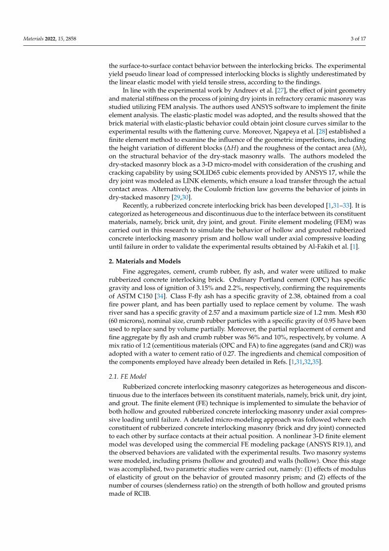
where ε1, ε2, ε3 are principal strains and ν′ is effective material Poisson’s ratio.By considering material nonlinearities, the compressive failure and tensile fracture
of masonry are governed by a von Mises failure surface with tension cutoff, as shown inFigure 4. in which σ1 and σ2 are the principal stresses, fm and ft are compressive and tensilestrength of masonry, and fo determines the initial yield surface, which is also governed bythe von Mises criterion [36], where assumed in this research.
Materials 2022, 15, x FOR PEER REVIEW 6 of 17
2.3. Constitutive Model
The proposed model is classified as a “detailed micro-model” where the brick was
represented by a solid finite element, and the contact interface (dry joints, head, and bed
joints) was represented by nonlinear target and contact elements. Target and contact ele-
ments were combined to describe the mechanical and structural behavior of a typical joint.
The joint model was built using two nonlinear elements, one target and one contact (con-
nected in parallel). All elements were defined according to existing elements in ANSYS
R19.1.
Due to the isotropic behavior and elastoplastic response of rubberized concrete inter-
locking bricks, a nonlinear plasticity model was selected. Therefore, multilinear stress-
strain constitutive law was employed in this study. The von Mises yield criterion is com-
bined with the hardening parameter in the multilinear isotropic hardening (MISO). Ac-
cording to the von Mises yield criterion, the material is assumed to yield once the equiv-
alent stress (��) is larger than the current yield stress (��). This can be expressed as Equa-
tion (1). On the other hand, von Mises or equivalent strain �� is computed by Equation
(4).
�� > �� > �3�� (1)
where �� is the second invariant of the deviatoric stress.
The equivalent stress (von Mises stress) can be expressed as Equations (2) and (4):
�� = �1
2(�� − ��)� + (�� − ��)� + (�� − ��)� (2)
�� = �3
2������ (3)
where ��, ��, �� are principal stresses, ��� is deviatoric stress.
�� =1
(1 + ��)�
1
2(�� − ��)� + (�� − ��)� + (�� − ��)� (4)
where ��, ��, �� are principal strains and �� is effective material Poisson’s ratio.
By considering material nonlinearities, the compressive failure and tensile fracture
of masonry are governed by a von Mises failure surface with tension cutoff, as shown in
Figure 4. in which �� and �� are the principal stresses, �� and �� are compressive and
tensile strength of masonry, and �� determines the initial yield surface, which is also gov-
erned by the von Mises criterion [36], where assumed in this research.
Figure 4. Yield and failure surface [36]. Figure 4. Yield and failure surface [36].
Before the tension cutoff surface is reached, the material is assumed to be elastic-plastic, of which the plastic behavior is represented by J2 plasticity as soon as the stressstate reaches the initial yield surface. The material exhibits a strain-hardening behaviorwhen the stress state is between the initial yield surface and the final failure surface. Strain
Materials 2022, 15, 2858 7 of 17
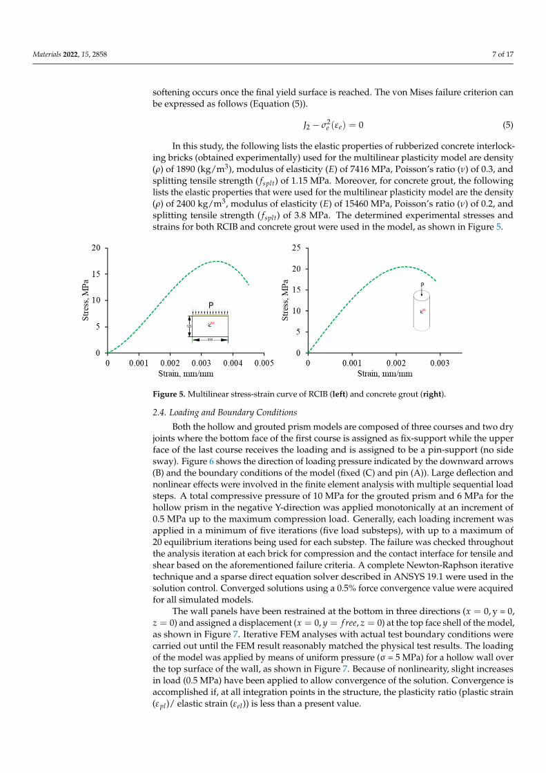
softening occurs once the final yield surface is reached. The von Mises failure criterion canbe expressed as follows (Equation (5)).
J2 − σ2e (εe) = 0 (5)
In this study, the following lists the elastic properties of rubberized concrete interlock-ing bricks (obtained experimentally) used for the multilinear plasticity model are density(ρ) of 1890 (kg/m3), modulus of elasticity (E) of 7416 MPa, Poisson’s ratio (ν) of 0.3, andsplitting tensile strength ( fsplt) of 1.15 MPa. Moreover, for concrete grout, the followinglists the elastic properties that were used for the multilinear plasticity model are the density(ρ) of 2400 kg/m3, modulus of elasticity (E) of 15460 MPa, Poisson’s ratio (ν) of 0.2, andsplitting tensile strength ( fsplt) of 3.8 MPa. The determined experimental stresses andstrains for both RCIB and concrete grout were used in the model, as shown in Figure 5.
Materials 2022, 15, x FOR PEER REVIEW 7 of 17
Before the tension cutoff surface is reached, the material is assumed to be elastic-
plastic, of which the plastic behavior is represented by �� plasticity as soon as the stress
state reaches the initial yield surface. The material exhibits a strain-hardening behavior
when the stress state is between the initial yield surface and the final failure surface. Strain
softening occurs once the final yield surface is reached. The von Mises failure criterion can
be expressed as follows (Equation (5)).
�� − ���(��) = 0 (5)
In this study, the following lists the elastic properties of rubberized concrete inter-
locking bricks (obtained experimentally) used for the multilinear plasticity model are den-
sity (�) of 1890 (kg/m3), modulus of elasticity (�) of 7416 MPa, Poisson’s ratio (�) of 0.3,
and splitting tensile strength (�����) of 1.15 MPa. Moreover, for concrete grout, the follow-
ing lists the elastic properties that were used for the multilinear plasticity model are the
density (�) of 2400 kg/m3, modulus of elasticity (�) of 15460 MPa, Poisson’s ratio (�) of 0.2,
and splitting tensile strength (�����) of 3.8 MPa. The determined experimental stresses and
strains for both RCIB and concrete grout were used in the model, as shown in Figure 5.
Figure 5. Multilinear stress-strain curve of RCIB (left) and concrete grout (right).
2.4. Loading and Boundary Conditions
Both the hollow and grouted prism models are composed of three courses and two
dry joints where the bottom face of the first course is assigned as fix-support while the
upper face of the last course receives the loading and is assigned to be a pin-support (no
side sway). Figure 6 shows the direction of loading pressure indicated by the downward
arrows (B) and the boundary conditions of the model (fixed (C) and pin (A)). Large de-
flection and nonlinear effects were involved in the finite element analysis with multiple
sequential load steps. A total compressive pressure of 10 MPa for the grouted prism and
6 MPa for the hollow prism in the negative Y-direction was applied monotonically at an
increment of 0.5 MPa up to the maximum compression load. Generally, each loading in-
crement was applied in a minimum of five iterations (five load substeps), with up to a
maximum of 20 equilibrium iterations being used for each substep. The failure was
checked throughout the analysis iteration at each brick for compression and the contact
interface for tensile and shear based on the aforementioned failure criteria. A complete
Newton-Raphson iterative technique and a sparse direct equation solver described in AN-
SYS 19.1 were used in the solution control. Converged solutions using a 0.5% force con-
vergence value were acquired for all simulated models.
Figure 5. Multilinear stress-strain curve of RCIB (left) and concrete grout (right).
2.4. Loading and Boundary Conditions
Both the hollow and grouted prism models are composed of three courses and two dryjoints where the bottom face of the first course is assigned as fix-support while the upperface of the last course receives the loading and is assigned to be a pin-support (no sidesway). Figure 6 shows the direction of loading pressure indicated by the downward arrows(B) and the boundary conditions of the model (fixed (C) and pin (A)). Large deflection andnonlinear effects were involved in the finite element analysis with multiple sequential loadsteps. A total compressive pressure of 10 MPa for the grouted prism and 6 MPa for thehollow prism in the negative Y-direction was applied monotonically at an increment of0.5 MPa up to the maximum compression load. Generally, each loading increment wasapplied in a minimum of five iterations (five load substeps), with up to a maximum of20 equilibrium iterations being used for each substep. The failure was checked throughoutthe analysis iteration at each brick for compression and the contact interface for tensile andshear based on the aforementioned failure criteria. A complete Newton-Raphson iterativetechnique and a sparse direct equation solver described in ANSYS 19.1 were used in thesolution control. Converged solutions using a 0.5% force convergence value were acquiredfor all simulated models.
The wall panels have been restrained at the bottom in three directions (x = 0, y = 0,z = 0) and assigned a displacement (x = 0, y = f ree, z = 0) at the top face shell of the model,as shown in Figure 7. Iterative FEM analyses with actual test boundary conditions werecarried out until the FEM result reasonably matched the physical test results. The loadingof the model was applied by means of uniform pressure (σ = 5 MPa) for a hollow wall overthe top surface of the wall, as shown in Figure 7. Because of nonlinearity, slight increasesin load (0.5 MPa) have been applied to allow convergence of the solution. Convergence isaccomplished if, at all integration points in the structure, the plasticity ratio (plastic strain(εpl)/ elastic strain (εel)) is less than a present value.

Materials 2022, 15, 2858 8 of 17Materials 2022, 15, x FOR PEER REVIEW 8 of 17
Figure 6. Load and boundary conditions of FE hollow and grouted prism.
The wall panels have been restrained at the bottom in three directions (� = 0, � =
0, � = 0) and assigned a displacement (� = 0, � = ����, � = 0) at the top face shell of the
model, as shown in Figure 7. Iterative FEM analyses with actual test boundary conditions
were carried out until the FEM result reasonably matched the physical test results. The
loading of the model was applied by means of uniform pressure (σ = 5 MPa) for a hollow
wall over the top surface of the wall, as shown in Figure 7. Because of nonlinearity, slight
increases in load (0.5 MPa) have been applied to allow convergence of the solution. Con-
vergence is accomplished if, at all integration points in the structure, the plasticity ratio
(plastic strain (���)/ elastic strain (���)) is less than a present value.
Figure 7. Load and boundary conditions of FE hollow wall.
Figure 6. Load and boundary conditions of FE hollow and grouted prism.
Materials 2022, 15, x FOR PEER REVIEW 8 of 17
Figure 6. Load and boundary conditions of FE hollow and grouted prism.
The wall panels have been restrained at the bottom in three directions (� = 0, � =
0, � = 0) and assigned a displacement (� = 0, � = ����, � = 0) at the top face shell of the
model, as shown in Figure 7. Iterative FEM analyses with actual test boundary conditions
were carried out until the FEM result reasonably matched the physical test results. The
loading of the model was applied by means of uniform pressure (σ = 5 MPa) for a hollow
wall over the top surface of the wall, as shown in Figure 7. Because of nonlinearity, slight
increases in load (0.5 MPa) have been applied to allow convergence of the solution. Con-
vergence is accomplished if, at all integration points in the structure, the plasticity ratio
(plastic strain (���)/ elastic strain (���)) is less than a present value.
Figure 7. Load and boundary conditions of FE hollow wall.
Figure 7. Load and boundary conditions of FE hollow wall.
3. Results3.1. RCIB Masonry Prisms (Hollow and Grouted)
The comparison between the experimental and finite element results of both hollowand grouted rubberized concrete interlocking prism is shown in Table 1, where kexp, Pexp,and Eexp are the stiffness, ultimate compression load, and modulus of elasticity, respectively,attained experimentally, whereas kFE, PFE, and EFE are the corresponding results attainedfrom finite element analysis.
Materials 2022, 15, 2858 9 of 17
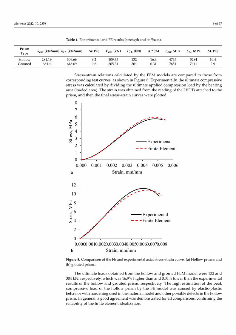
Table 1. Experimental and FE results (strength and stiffness).
PrismType kexp (kN/mm) kFE (kN/mm) ∆k (%) Pexp (kN) PFE (kN) ∆P (%) Eexp MPa EFE MPa ∆E (%)
Hollow 281.19 309.66 9.2 109.65 132 16.9 4735 5284 10.4Grouted 684.4 618.69 9.6 305.34 304 0.31 7654 7441 2.9
Stress-strain relations calculated by the FEM models are compared to those fromcorresponding test curves, as shown in Figure 8. Experimentally, the ultimate compressivestress was calculated by dividing the ultimate applied compression load by the bearingarea (loaded area). The strain was obtained from the reading of the LVDTs attached to theprism, and then the final stress-strain curves were plotted.
Materials 2022, 15, x FOR PEER REVIEW 9 of 17
3. Results
3.1. RCIB Masonry Prisms (Hollow and Grouted)
The comparison between the experimental and finite element results of both hollow
and grouted rubberized concrete interlocking prism is shown in Table 1, where ���� ,
���� , and ���� are the stiffness, ultimate compression load, and modulus of elasticity, re-
spectively, attained experimentally, whereas ��� , ��� , and ��� are the corresponding re-
sults attained from finite element analysis.
Table 1. Experimental and FE results (strength and stiffness).
Prism Type ���� (kN/mm) ��� (kN/mm) �� (%) ���� (kN) ��� (kN) �� (%) ���� MPa ���
MPa �� (%)
Hollow 281.19 309.66 9.2 109.65 132 16.9 4735 5284 10.4
Grouted 684.4 618.69 9.6 305.34 304 0.31 7654 7441 2.9
Stress-strain relations calculated by the FEM models are compared to those from cor-
responding test curves, as shown in Figure 8. Experimentally, the ultimate compressive
stress was calculated by dividing the ultimate applied compression load by the bearing
area (loaded area). The strain was obtained from the reading of the LVDTs attached to the
prism, and then the final stress-strain curves were plotted.
Figure 8. Comparison of the FE and experimental axial stress-strain curve. (a) Hollow prisms and
(b) grouted prisms.
0
1
2
3
4
5
6
7
8
0.000 0.001 0.002 0.003 0.004 0.005 0.006
Str
ess,
MP
a
Strain, mm/mm
Experimenal
Finite Element
a
)
0
2
4
6
8
10
12
0.0000.0010.0020.0030.0040.0050.0060.0070.008
Str
ess,
MP
a
Strain, mm/mm
ExperimentalFinite Element
b
Figure 8. Comparison of the FE and experimental axial stress-strain curve. (a) Hollow prisms and(b) grouted prisms.
The ultimate loads obtained from the hollow and grouted FEM model were 132 and304 kN, respectively, which was 16.9% higher than and 0.31% lower than the experimentalresults of the hollow and grouted prism, respectively. The high estimation of the peakcompressive load of the hollow prism by the FE model was caused by elastic-plasticbehavior with hardening used in the material model and other possible defects in the hollowprism. In general, a good agreement was demonstrated for all comparisons, confirming thereliability of the finite element idealization.
Materials 2022, 15, 2858 10 of 17
The experimental modulus of elasticity of the rubberized concrete interlocking hollowprism of 4735 MPa was increased to 5284 MPa while reduced from 7654 MPa experimentallyto 7441 MPa on FE for grouted prism. These differences are due to the complex combinedeffect of the material and dry contact nonlinearity. However, the elastic modulus predictedby the finite element model compares very well with that attained from the experimentaltesting (∆E ≤ 10), as shown in Table 1.
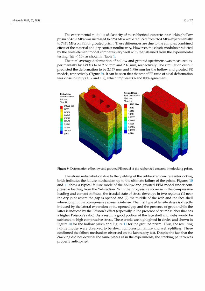
The total average deformation of hollow and grouted specimens was measured ex-perimentally by LVDTs to be 2.55 mm and 2.16 mm, respectively. The simulation outputpredicted the deformation to be 2.167 mm and 1.786 mm for the hollow and grouted FEmodels, respectively (Figure 9). It can be seen that the test of FE ratio of axial deformationwas close to unity (1.17 and 1.2), which implies 83% and 80% agreement.
Materials 2022, 15, x FOR PEER REVIEW 10 of 17
The ultimate loads obtained from the hollow and grouted FEM model were 132 and
304 kN, respectively, which was 16.9% higher than and 0.31% lower than the experimental
results of the hollow and grouted prism, respectively. The high estimation of the peak
compressive load of the hollow prism by the FE model was caused by elastic-plastic be-
havior with hardening used in the material model and other possible defects in the hollow
prism. In general, a good agreement was demonstrated for all comparisons, confirming
the reliability of the finite element idealization.
The experimental modulus of elasticity of the rubberized concrete interlocking hol-
low prism of 4735 MPa was increased to 5284 MPa while reduced from 7654 MPa experi-
mentally to 7441 MPa on FE for grouted prism. These differences are due to the complex
combined effect of the material and dry contact nonlinearity. However, the elastic modu-
lus predicted by the finite element model compares very well with that attained from the
experimental testing (Δ� ≤ 10), as shown in Table 1.
The total average deformation of hollow and grouted specimens was measured ex-
perimentally by LVDTs to be 2.55 mm and 2.16 mm, respectively. The simulation output
predicted the deformation to be 2.167 mm and 1.786 mm for the hollow and grouted FE
models, respectively (Figure 9). It can be seen that the test of FE ratio of axial deformation
was close to unity (1.17 and 1.2), which implies 83% and 80% agreement.
Figure 9. Deformation of hollow and grouted FE model of the rubberized concrete interlocking prism.
The stress redistribution due to the yielding of the rubberized concrete interlocking
brick indicates the failure mechanism up to the ultimate failure of the prism. Figures 10 and
11 show a typical failure mode of the hollow and grouted FEM model under compressive
loading from the Y-direction. With the progressive increase in the compressive loading and
contact stiffness, the triaxial state of stress develops in two regions: (1) near the dry joint
where the gap is opened and (2) the middle of the web and the face shell where longitudinal
compressive stress is intense. The first type of tensile stress is directly induced by the lateral
expansion at the opened gap and the presence of grout, while the latter is induced by the
Poisson’s effect (especially in the presence of crumb rubber that has a higher Poisson’s ratio).
As a result, a good portion of the face shell and webs would be subjected to high compres-
sive stress. These cracks are highlighted in circles and shown in Figure 10 for the hollow
prism and Figure 11 for the grouted prism. Thus, the resulting failure modes were observed
to be shear compression failure and web splitting. These confirmed the failure mechanism
observed on the laboratory test. Despite the fact that the cracking did not occur at the same
places as in the experiments, the cracking pattern was properly anticipated.
Figure 9. Deformation of hollow and grouted FE model of the rubberized concrete interlocking prism.
The strain redistribution due to the yielding of the rubberized concrete interlockingbrick indicates the failure mechanism up to the ultimate failure of the prism. Figures 10and 11 show a typical failure mode of the hollow and grouted FEM model under com-pressive loading from the Y-direction. With the progressive increase in the compressiveloading and contact stiffness, the triaxial state of stress develops in two regions: (1) nearthe dry joint where the gap is opened and (2) the middle of the web and the face shellwhere longitudinal compressive stress is intense. The first type of tensile stress is directlyinduced by the lateral expansion at the opened gap and the presence of grout, while thelatter is induced by the Poisson’s effect (especially in the presence of crumb rubber that hasa higher Poisson’s ratio). As a result, a good portion of the face shell and webs would besubjected to high compressive stress. These cracks are highlighted in circles and shown inFigure 10 for the hollow prism and Figure 11 for the grouted prism. Thus, the resultingfailure modes were observed to be shear compression failure and web splitting. Theseconfirmed the failure mechanism observed on the laboratory test. Despite the fact that thecracking did not occur at the same places as in the experiments, the cracking pattern wasproperly anticipated.

Materials 2022, 15, 2858 11 of 17Materials 2022, 15, x FOR PEER REVIEW 11 of 17
Figure 10. Failure mode (equivalent elastic strain) of hollow prism experimentally and FE model.
Figure 11. Failure mode (equivalent elastic strain) of grouted prism experimentally and FE model.
Generally, for interlocking masonry hollow or grouted prisms, the average experi-
mental to FE ratios of ultimate compression load, peak stress and strain, stiffness, and
modulus of elasticity were all close to unity. As a result, it was confirmed that the FEM
model produces stiffness and strength values that correlate well with laboratory test find-
ings; thus, it gives a valuable platform for simulating and understanding the behavior and
failure mechanism of the rubberized concrete interlocking masonry prism.
3.2. RCIB Masonry Wall (Hollow)
The established FEM models of the rubberized concrete interlocking masonry wall
panels were validated with the laboratory test results discussed in [1]. The structural
properties obtained from the FE simulation were tabulated and used as a means of com-
parison of the laboratory test results, as shown in Table 2.
Figure 10. Failure mode (equivalent elastic strain) of hollow prism experimentally and FE model.
Materials 2022, 15, x FOR PEER REVIEW 11 of 17
Figure 10. Failure mode (equivalent elastic strain) of hollow prism experimentally and FE model.
Figure 11. Failure mode (equivalent elastic strain) of grouted prism experimentally and FE model.
Generally, for interlocking masonry hollow or grouted prisms, the average experi-
mental to FE ratios of ultimate compression load, peak stress and strain, stiffness, and
modulus of elasticity were all close to unity. As a result, it was confirmed that the FEM
model produces stiffness and strength values that correlate well with laboratory test find-
ings; thus, it gives a valuable platform for simulating and understanding the behavior and
failure mechanism of the rubberized concrete interlocking masonry prism.
3.2. RCIB Masonry Wall (Hollow)
The established FEM models of the rubberized concrete interlocking masonry wall
panels were validated with the laboratory test results discussed in [1]. The structural
properties obtained from the FE simulation were tabulated and used as a means of com-
parison of the laboratory test results, as shown in Table 2.
Figure 11. Failure mode (equivalent elastic strain) of grouted prism experimentally and FE model.
Generally, for interlocking masonry hollow or grouted prisms, the average experimen-tal to FE ratios of ultimate compression load, peak stress and strain, stiffness, and modulusof elasticity were all close to unity. As a result, it was confirmed that the FEM modelproduces stiffness and strength values that correlate well with laboratory test findings; thus,it gives a valuable platform for simulating and understanding the behavior and failuremechanism of the rubberized concrete interlocking masonry prism.
3.2. RCIB Masonry Wall (Hollow)
The established FEM models of the rubberized concrete interlocking masonry wallpanels were validated with the laboratory test results discussed in [1]. The structural prop-erties obtained from the FE simulation were tabulated and used as a means of comparisonof the laboratory test results, as shown in Table 2.

Materials 2022, 15, 2858 12 of 17
Table 2. Experimental and FE findings for tested masonry walls.
PropertyHollow Wall Results Grouted Wall Results
EXP FE EXP/FE EXP FE EXP/FE
Ultimate load, kN 181 216 0.84 424.8 510 0.83
Compressivestrength, MPa 3.87 3.73 1.04 5.75 7.62 0.75
Elastic modulus, MPa 727.42 845.4 0.86 1778.34 2320.2 0.76
Ultimate strain atfailure, mm/mm 0.0055 0.0049 1.12 0.00436 0.00325 1.34
Stiffness, kN/mm 27 35 0.77 103.23 131.2 0.79
Deformation, mm 6.78 5.33 1.27 5.54 4.96 1.12
Table 2 shows the comparison between the experimental and finite element results ofboth hollow and grouted rubberized concrete interlocking wall panels. The experimentalcompressive strength of the rubberized concrete interlocking hollow wall panel of 3.87 MPawas slightly decreased to 3.73 MPa while highly increased from 5.75 MPa experimentallyto 7.62 MPa in the FE model for the grouted wall panel. These differences are due to thecomplex combined effect of the material and dry contact nonlinearity. However, elasticmodulus, stiffness, and axial deformation predicted by the finite element model comparedwell with that attained from the physical testing.
The FE failure mechanism is presented as the equivalent elastic strain for both hollowand grouted wall panels and then compared with the failure mode of the tested specimens,as shown in Figure 12. It is clear that the failure mode and strain concentration arecomparable in both FE and experimental walls. With the progressive increase in thecompressive loading and contact stiffness, the triaxial state of stress develops in tworegions: (1) near the dry joint where the gap is opened and (2) the middle of the web andthe face-shell where longitudinal compressive stress is intense. These confirmed the failuremechanism observed on the laboratory test and described in Section 4.3 of Ref. [1]. Eventhough the cracking was not at the exact locations as those in the experiments, the failuremode was accurately predicted. In general, it was observed that two major failures wereexhibited for both hollow and grouted wall panels—a shear mode failure along the bed orhead joint and a flexural failure of the wall.
Materials 2022, 15, x FOR PEER REVIEW 12 of 17
Table 2. Experimental and FE findings for tested masonry walls.
Property Hollow Wall Results Grouted Wall Results
��� �� ���/�� ��� �� ���/��
Ultimate load, kN 181 216 0.84 424.8 510 0.83
Compressive
strength, MPa 3.87 3.73 1.04 5.75 7.62 0.75
Elastic modulus, MPa 727.42 845.4 0.86 1778.34 2320.2 0.76
Ultimate strain at fail-
ure, mm/mm 0.0055 0.0049 1.12 0.00436 0.00325 1.34
Stiffness, kN/mm 27 35 0.77 103.23 131.2 0.79
Deformation, mm 6.78 5.33 1.27 5.54 4.96 1.12
Table 2 shows the comparison between the experimental and finite element results
of both hollow and grouted rubberized concrete interlocking wall panels. The experi-
mental compressive strength of the rubberized concrete interlocking hollow wall panel of
3.87 MPa was slightly decreased to 3.73 MPa while highly increased from 5.75 MPa exper-
imentally to 7.62 MPa in the FE model for the grouted wall panel. These differences are
due to the complex combined effect of the material and dry contact nonlinearity. How-
ever, elastic modulus, stiffness, and axial deformation predicted by the finite element
model compared well with that attained from the physical testing.
The FE failure mechanism is presented as the vertical stress distribution for both hol-
low and grouted wall panels and then compared with the failure mode of the tested spec-
imens, as shown in Figure 12. It is clear that the failure mode and stress concentration are
comparable in both FE and experimental walls. With the progressive increase in the com-
pressive loading and contact stiffness, the triaxial state of stress develops in two regions:
(1) near the dry joint where the gap is opened and (2) the middle of the web and the face-
shell where longitudinal compressive stress is intense. These confirmed the failure mech-
anism observed on the laboratory test and described in Section 4.3 of Ref. [1]. Even though
the cracking was not at the exact locations as those in the experiments, the failure mode
was accurately predicted. In general, it was observed that two major failures were exhib-
ited for both hollow and grouted wall panels—a shear mode failure along the bed or head
joint and a flexural failure of the wall.
Figure 12. Failure mode (equivalent elastic strain) of hollow wall experimentally and FE model. Figure 12. Failure mode (equivalent elastic strain) of hollow wall experimentally and FE model.
Materials 2022, 15, 2858 13 of 17
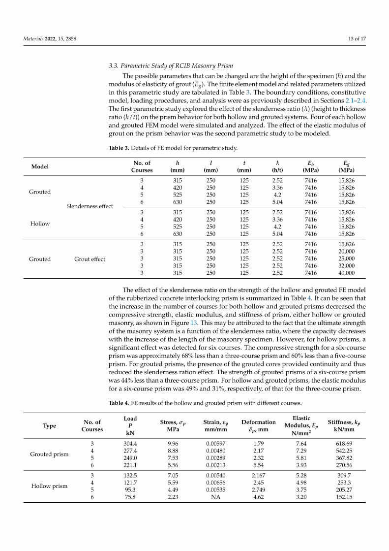
3.3. Parametric Study of RCIB Masonry Prism
The possible parameters that can be changed are the height of the specimen (h) and themodulus of elasticity of grout (Eg). The finite element model and related parameters utilizedin this parametric study are tabulated in Table 3. The boundary conditions, constitutivemodel, loading procedures, and analysis were as previously described in Sections 2.1–2.4.The first parametric study explored the effect of the slenderness ratio (λ) (height to thicknessratio (h/t)) on the prism behavior for both hollow and grouted systems. Four of each hollowand grouted FEM model were simulated and analyzed. The effect of the elastic modulus ofgrout on the prism behavior was the second parametric study to be modeled.
Table 3. Details of FE model for parametric study.
Model No. ofCourses
h(mm)
l(mm)
t(mm)
λ(h/t)
Eb(MPa)
Eg(MPa)
Grouted
Slenderness effect
3 315 250 125 2.52 7416 15,8264 420 250 125 3.36 7416 15,8265 525 250 125 4.2 7416 15,8266 630 250 125 5.04 7416 15,826
Hollow
3 315 250 125 2.52 7416 15,8264 420 250 125 3.36 7416 15,8265 525 250 125 4.2 7416 15,8266 630 250 125 5.04 7416 15,826
Grouted Grout effect
3 315 250 125 2.52 7416 15,8263 315 250 125 2.52 7416 20,0003 315 250 125 2.52 7416 25,0003 315 250 125 2.52 7416 32,0003 315 250 125 2.52 7416 40,000
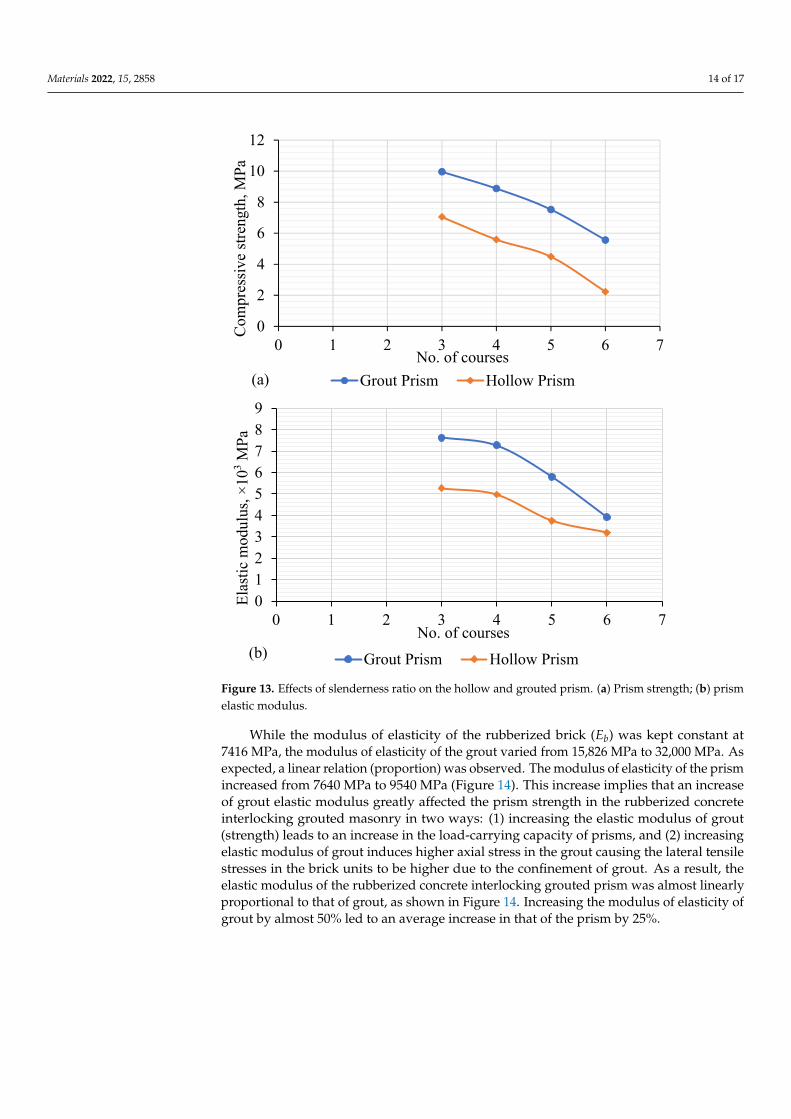
The effect of the slenderness ratio on the strength of the hollow and grouted FE modelof the rubberized concrete interlocking prism is summarized in Table 4. It can be seen thatthe increase in the number of courses for both hollow and grouted prisms decreased thecompressive strength, elastic modulus, and stiffness of prism, either hollow or groutedmasonry, as shown in Figure 13. This may be attributed to the fact that the ultimate strengthof the masonry system is a function of the slenderness ratio, where the capacity decreaseswith the increase of the length of the masonry specimen. However, for hollow prisms, asignificant effect was detected for six courses. The compressive strength for a six-courseprism was approximately 68% less than a three-course prism and 60% less than a five-courseprism. For grouted prisms, the presence of the grouted cores provided continuity and thusreduced the slenderness ration effect. The strength of grouted prisms of a six-course prismwas 44% less than a three-course prism. For hollow and grouted prisms, the elastic modulusfor a six-course prism was 49% and 31%, respectively, of that for the three-course prism.
Table 4. FE results of the hollow and grouted prism with different courses.
Type No. ofCourses
LoadP
kN
Stress, σpMPa
Strain, εpmm/mm
Deformationδp, mm
ElasticModulus, Ep
N/mm2
Stiffness, kpkN/mm
Grouted prism
3 304.4 9.96 0.00597 1.79 7.64 618.694 277.4 8.88 0.00480 2.17 7.29 542.255 249.0 7.53 0.00289 2.32 5.81 367.826 221.1 5.56 0.00213 5.54 3.93 270.56
Hollow prism
3 132.5 7.05 0.00540 2.167 5.28 309.74 121.7 5.59 0.00656 2.45 4.98 253.35 95.3 4.49 0.00535 2.749 3.75 205.276 75.8 2.23 NA 4.62 3.20 152.15
Materials 2022, 15, 2858 14 of 17
Materials 2022, 15, x FOR PEER REVIEW 14 of 17
6 221.1 5.56 0.00213 5.54 3.93 270.56
Hollow prism
3 132.5 7.05 0.00540 2.167 5.28 309.7
4 121.7 5.59 0.00656 2.45 4.98 253.3
5 95.3 4.49 0.00535 2.749 3.75 205.27
6 75.8 2.23 NA 4.62 3.20 152.15
Figure 13. Effects of slenderness ratio on the hollow and grouted prism. (a) Prism strength; (b)
prism elastic modulus.
While the modulus of elasticity of the rubberized brick (��) was kept constant at 7416
MPa, the modulus of elasticity of the grout varied from 15,826 MPa to 32,000 MPa. As
expected, a linear relation (proportion) was observed. The modulus of elasticity of the
prism increased from 7640 MPa to 9540 MPa (Figure 14). This increase implies that an
increase of grout elastic modulus greatly affected the prism strength in the rubberized
concrete interlocking grouted masonry in two ways: (1) increasing the elastic modulus of
grout (strength) leads to an increase in the load-carrying capacity of prisms, and (2) in-
creasing elastic modulus of grout induces higher axial stress in the grout causing the lat-
eral tensile stresses in the brick units to be higher due to the confinement of grout. As a
result, the elastic modulus of the rubberized concrete interlocking grouted prism was al-
most linearly proportional to that of grout, as shown in Figure 14. Increasing the modulus
of elasticity of grout by almost 50% led to an average increase in that of the prism by 25%.
0
2
4
6
8
10
12
0 1 2 3 4 5 6 7
Com
pres
sive
str
engt
h, M
Pa
No. of courses
Grout Prism Hollow Prism(a)
0
1
2
3
4
5
6
7
8
9
0 1 2 3 4 5 6 7
Ela
stic
mod
ulus
, ×
103
MP
a
No. of courses
Grout Prism Hollow Prism(b)
Figure 13. Effects of slenderness ratio on the hollow and grouted prism. (a) Prism strength; (b) prismelastic modulus.
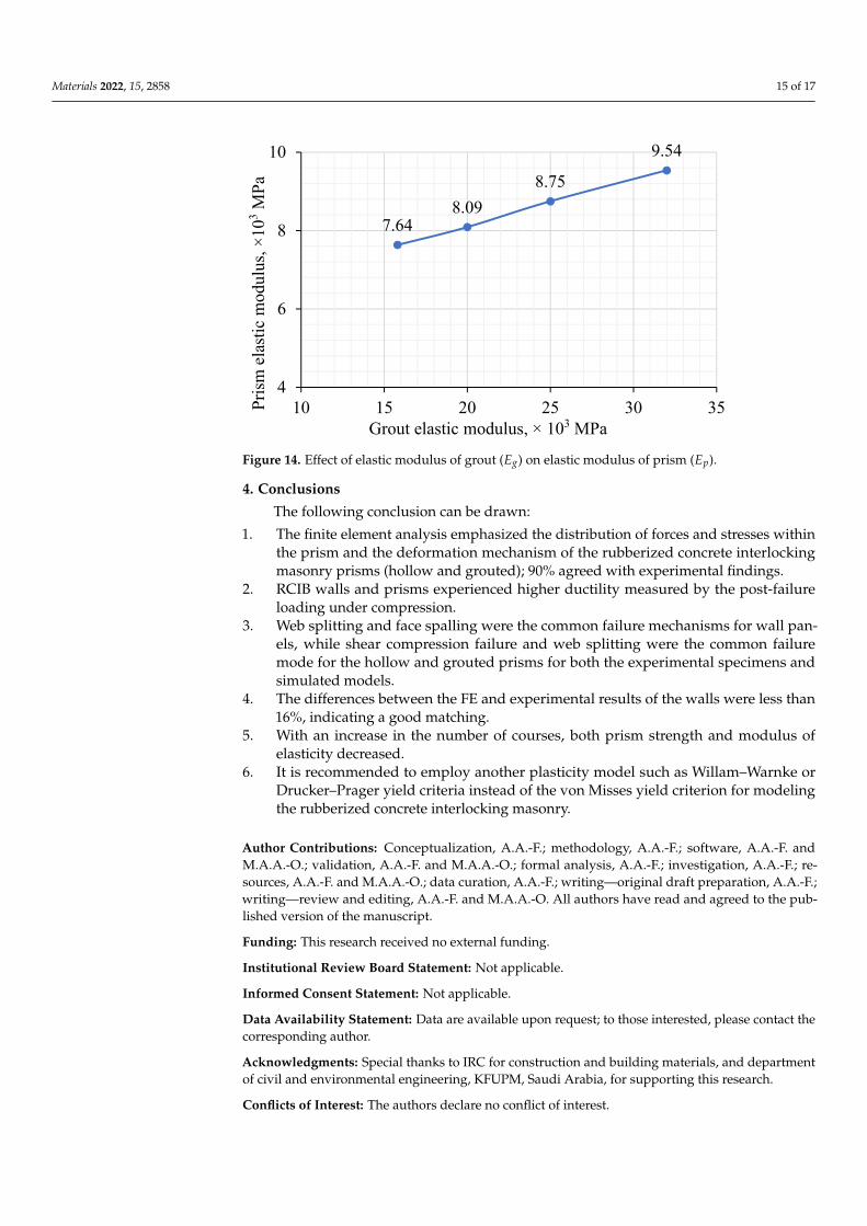
While the modulus of elasticity of the rubberized brick (Eb) was kept constant at7416 MPa, the modulus of elasticity of the grout varied from 15,826 MPa to 32,000 MPa. Asexpected, a linear relation (proportion) was observed. The modulus of elasticity of the prismincreased from 7640 MPa to 9540 MPa (Figure 14). This increase implies that an increaseof grout elastic modulus greatly affected the prism strength in the rubberized concreteinterlocking grouted masonry in two ways: (1) increasing the elastic modulus of grout(strength) leads to an increase in the load-carrying capacity of prisms, and (2) increasingelastic modulus of grout induces higher axial stress in the grout causing the lateral tensilestresses in the brick units to be higher due to the confinement of grout. As a result, theelastic modulus of the rubberized concrete interlocking grouted prism was almost linearlyproportional to that of grout, as shown in Figure 14. Increasing the modulus of elasticity ofgrout by almost 50% led to an average increase in that of the prism by 25%.
Materials 2022, 15, 2858 15 of 17Materials 2022, 15, x FOR PEER REVIEW 15 of 17
Figure 14. Effect of elastic modulus of grout (��) on elastic modulus of prism (��).
4. Conclusions
The following conclusion can be drawn:
1. The finite element analysis emphasized the distribution of forces and stresses within
the prism and the deformation mechanism of the rubberized concrete interlocking
masonry prisms (hollow and grouted); 90% agreed with experimental findings.
2. RCIB walls and prisms experienced higher ductility measured by the post-failure
loading under compression.
3. Web splitting and face spalling were the common failure mechanisms for wall panels,
while shear compression failure and web splitting were the common failure mode
for the hollow and grouted prisms for both the experimental specimens and simu-
lated models.
4. The differences between the FE and experimental results of the walls were less than
16%, indicating a good matching.
5. With an increase in the number of courses, both prism strength and modulus of elas-
ticity decreased.
6. It is recommended to employ another plasticity model such as Willam–Warnke or
Drucker–Prager yield criteria instead of the von Misses yield criterion for modeling
the rubberized concrete interlocking masonry.
Author Contributions: Conceptualization, A.A.-F.; methodology, A.A.-F.; software, A.A.-F. and
M.A.A.-O.; validation, A.A.-F. and M.A.A.-O.; formal analysis, A.A.-F.; investigation, A.A.-F.; re-
sources, A.A.-F. and M.A.A.-O.; data curation, A.A.-F.; writing—original draft preparation, A.A.-F.;
writing—review and editing, A.A.-F. and M.A.A.-O. All authors have read and agreed to the pub-
lished version of the manuscript.
Funding: This research received no external funding.
Institutional Review Board Statement: Not applicable.
Informed Consent Statement: Not applicable.
Data Availability Statement: Data are available upon request; to those interested, please contact
the corresponding author.
Acknowledgments: Special thanks to IRC for construction and building materials, and department
of civil and environmental engineering, KFUPM, Saudi Arabia, for supporting this research.
Conflicts of Interest: The authors declare no conflict of interest.
7.648.09
8.75
9.54
4
6
8
10
10 15 20 25 30 35Pri
sm e
last
ic m
odul
us, ×
103
MP
a
Grout elastic modulus, × 103 MPa
Figure 14. Effect of elastic modulus of grout (Eg) on elastic modulus of prism (Ep).
4. Conclusions
The following conclusion can be drawn:
1. The finite element analysis emphasized the distribution of forces and stresses withinthe prism and the deformation mechanism of the rubberized concrete interlockingmasonry prisms (hollow and grouted); 90% agreed with experimental findings.
2. RCIB walls and prisms experienced higher ductility measured by the post-failureloading under compression.
3. Web splitting and face spalling were the common failure mechanisms for wall pan-els, while shear compression failure and web splitting were the common failuremode for the hollow and grouted prisms for both the experimental specimens andsimulated models.
4. The differences between the FE and experimental results of the walls were less than16%, indicating a good matching.
5. With an increase in the number of courses, both prism strength and modulus ofelasticity decreased.
6. It is recommended to employ another plasticity model such as Willam–Warnke orDrucker–Prager yield criteria instead of the von Misses yield criterion for modelingthe rubberized concrete interlocking masonry.
Author Contributions: Conceptualization, A.A.-F.; methodology, A.A.-F.; software, A.A.-F. andM.A.A.-O.; validation, A.A.-F. and M.A.A.-O.; formal analysis, A.A.-F.; investigation, A.A.-F.; re-sources, A.A.-F. and M.A.A.-O.; data curation, A.A.-F.; writing—original draft preparation, A.A.-F.;writing—review and editing, A.A.-F. and M.A.A.-O. All authors have read and agreed to the pub-lished version of the manuscript.
Funding: This research received no external funding.
Institutional Review Board Statement: Not applicable.
Informed Consent Statement: Not applicable.
Data Availability Statement: Data are available upon request; to those interested, please contact thecorresponding author.
Acknowledgments: Special thanks to IRC for construction and building materials, and departmentof civil and environmental engineering, KFUPM, Saudi Arabia, for supporting this research.
Conflicts of Interest: The authors declare no conflict of interest.
Materials 2022, 15, 2858 16 of 17
References1. Al-Fakih, A.; Wahab, M.M.A.; Mohammed, B.S.; Liew, M.S.; Wan Abdullah Zawawi, N.A.; As’ad, S. Experimental study on axial
compressive behavior of rubberized interlocking masonry walls. J. Build. Eng. 2020, 29, 101107. [CrossRef]2. Al-Fakih, A.; Mohammed, B.S.; Liew, M.S. Behavior of the Dry Bed Joint in the Mortarless Interlocking Masonry System: An
Overview. Civ. Eng. Res. J. 2018, 4, 5.3. Al-Fakih, A.; Mohammed, B.S.; Nuruddin, F.; Nikbakht, E. Development of Interlocking Masonry Bricks and Its’ Structural Behaviour:
A Review Paper; IOP Conference Series: Earth and Environmental Science; IOP Publishing: Bristol, UK, 2018; p. 012127.4. Duarte, A.P.C.; Silva, B.A.; Silvestre, N.; de Brito, J.; Júlio, E. Mechanical characterization of rubberized concrete using an
image-processing/XFEM coupled procedure. Compos. Part B Eng. 2015, 78, 214–226. [CrossRef]5. Lubliner, J.; Oliver, J.; Oller, S.; Oñate, E. A plastic-damage model for concrete. Int. J. Solids Struct. 1989, 25, 299–326. [CrossRef]6. Zhou, S.; Zhu, H.; Ju, J.W.; Yan, Z.; Chen, Q. Modeling microcapsule-enabled self-healing cementitious composite materials using
discrete element method. Int. J. Damage Mech. 2017, 26, 340–357. [CrossRef]7. Zhao, X.; Dong, Q.; Chen, X.; Ni, F. Meso-cracking characteristics of rubberized cement-stabilized aggregate by discrete element
method. J. Clean. Prod. 2021, 316, 128374. [CrossRef]8. Mechtcherine, V.; Shyshko, S. Simulating the behaviour of fresh concrete with the Distinct Element Method–Deriving model
parameters related to the yield stress. Cem. Concr. Compos. 2015, 55, 81–90. [CrossRef]9. Weber, M.; Thoma, K.; Hofmann, J. Finite element analysis of masonry under a plane stress state. Eng. Struct. 2021, 226, 111214.
[CrossRef]10. Zeng, B.; Li, Y.; Cruz Noguez, C. Modeling and parameter importance investigation for simulating in-plane and out-of-plane
behaviors of un-reinforced masonry walls. Eng. Struct. 2021, 248, 113233. [CrossRef]11. Laurenco, P.; Rots, J.G.; Blaauwendraad, J. Two approaches for the analysis of masonry structures: Micro and macro-modeling.
HERON 1995, 40, 313–340.12. Barraza, C.; Andrés, J.; Meskouris, K. Numerical Model for Nonlinear Analysis of Masonry Walls; Lehrstuhl für Baustatik und
Baudynamik: Aachen, Germany, 2012.13. Rekik, A.; Allaoui, S.; Gasser, A.; Blond, E.; Andreev, K.; Sinnema, S. Experiments and nonlinear homogenization sustaining
mean-field theories for refractory mortarless masonry: The classical secant procedure and its improved variants. Eur. J. Mech. ASolids 2015, 49, 67–81. [CrossRef]
14. Lourenço, P.J.B.B. Computational Strategies for Masonry Structures. Ph.D. Thesis, Faculdade de Engenharia da Universidade doPorto, Porto, Portugal, 1997.
15. Oliveira, R.L.G.; Rodrigues, J.P.C.; Pereira, J.M.; Lourenço, P.B.; Ulrich Marschall, H. Normal and tangential behaviour of dryjoints in refractory masonry. Eng. Struct. 2021, 243, 112600. [CrossRef]
16. Senthivel, R.; Lourenço, P.B. Finite element modelling of deformation characteristics of historical stone masonry shear walls. Eng.Struct. 2009, 31, 1930–1943. [CrossRef]
17. Martínez, M.; Atamturktur, S. Experimental and numerical evaluation of reinforced dry-stacked concrete masonry walls. J. Build.Eng. 2019, 22, 181–191. [CrossRef]
18. Al-Wathaf, A.H. 3D Finite Element Analysis of Hollow Concrete Block Masonry. J. Sci. Technol. 2009, 14, 26–35.19. Oh, K.-H. Development and Investigation of Failure Mechanism of Interlocking Mortarless Block Masonry Systems. Doctoral
Dissertation, Drexel University, Philadelphia, PA, USA, 1994.20. Alpa, G.; Gambarotta, L.; Monetto, I. Dry block assembly continuum modelling for the in-plane analysis of shear walls. Comput.
Methods Struct. Mason. 1998, 4, 111–119.21. Thanoon, W.A.; Alwathaf, A.H.; Noorzaei, J.; Jaafar, M.S.; Abdulkadir, M.R. Finite element analysis of interlocking mortarless
hollow block masonry prism. Comput. Struct. 2008, 86, 520–528. [CrossRef]22. Thanoon, W.A.; Alwathaf, A.H.; Noorzaei, J.; Jaafar, M.S.; Abdulkadir, M.R. Nonlinear finite element analysis of grouted and
ungrouted hollow interlocking mortarless block masonry system. Eng. Struct. 2008, 30, 1560–1572. [CrossRef]23. Shi, T.; Zhang, X.; Hao, H.; Chen, C. Experimental and numerical investigation on the compressive properties of interlocking
blocks. Eng. Struct. 2021, 228, 111561. [CrossRef]24. Oliveira, R.L.G.; Rodrigues, J.P.C.; Pereira, J.M.; Lourenço, P.B.; Marschall, H.U. Thermomechanical behaviour of refractory
dry-stacked masonry walls under uniaxial compression. Eng. Struct. 2021, 240, 112361. [CrossRef]25. Chewe Ngapeya, G.G.; Waldmann, D. Experimental and analytical analysis of the load-bearing capacity Pu of improved
dry-stacked masonry. J. Build. Eng. 2020, 27, 100927. [CrossRef]26. Ayed, H.B.; Limam, O.; Aidi, M.; Jelidi, A. Experimental and numerical study of Interlocking Stabilized Earth Blocks mechanical
behavior. J. Build. Eng. 2016, 7, 207–216. [CrossRef]27. Andreev, K.; Sinnema, S.; Rekik, A.; Allaoui, S.; Blond, E.; Gasser, A. Compressive behaviour of dry joints in refractory ceramic
masonry. Constr. Build. Mater. 2012, 34, 402–408. [CrossRef]28. Chewe Ngapeya, G.G.; Waldmann, D.; Scholzen, F. Impact of the height imperfections of masonry blocks on the load bearing
capacity of dry-stack masonry walls. Constr. Build. Mater. 2018, 165, 898–913. [CrossRef]29. Gasser, A.; Terny-Rebeyrotte, K.; Boisse, P. Modelling of joint effects on refractory lining behaviour. Proc. Inst. Mech. Eng. Part L J.
Mater. Des. Appl. 2004, 218, 19–28. [CrossRef]

Materials 2022, 15, 2858 17 of 17
30. Brulin, J.; Blond, E.; de Bilbao, E.; Rekik, A.; Landreau, M.; Gasser, A.; Colleville, Y. Methodology for brick/mortar interfacestrength characterization at high temperature. Constr. Build. Mater. 2020, 265, 120565. [CrossRef]
31. Al-Fakih, A.; Mohammed, B.S.; Liew, M.S.; Alaloul, W.S.; Adamu, M.; Khed, V.C.; Dahim, M.A.; Al-Mattarneh, H. Mechanicalbehavior of rubberized interlocking bricks for masonry structural applications. Int. J. Civ. Eng. Technol. 2018, 9, 185–193.
32. Al-Fakih, A.; Mohammed, B.S.; Liew, M.S.; Alaloul, W.S. Physical properties of the rubberized interlocking masonry brick. Int. J.Civ. Eng. Technol. 2018, 9, 656–664.
33. Al-Fakih, A.; Mohammed, B.S.; Wahab, M.M.A.; Liew, M.S.; Mugahed Amran, Y.H.; Alyousef, R.; Alabduljabbar, H. Characteristiccompressive strength correlation of rubberized concrete interlocking masonry wall. Structures 2020, 26, 169–184. [CrossRef]
34. ASTM C150/C150M-17; Standard Specification for Portland Cement. ASTM International: West Conshohocken, PA, USA, 2017.35. Al-Fakih, A.; Mohammed, B.S.; Wahab, M.M.A.; Liew, M.S.; Mugahed Amran, Y.H. Flexural behavior of rubberized concrete
interlocking masonry walls under out-of-plane load. Constr. Build. Mater. 2020, 263, 120661. [CrossRef]36. Mohammed, M.S. Finite element analysis of unreinforced masonry walls. Al-Rafidain Eng. J. (AREJ) 2010, 18, 55–68. [CrossRef]
Copyright © 2022 FDOKUMEN