FILM & MICA CAPACITORS - Exxelia
184
FILM & MICA CAPACITORS www.dearbornelectronics.com
-
Upload
khangminh22 -
Category
Documents
-
view
0 -
download
0
Transcript of FILM & MICA CAPACITORS - Exxelia

1221 North US Highway 17-92Longwood, Florida 32750T 407 695-6562 • F 407 695-6889www.dearbornelectronics.com
FILM & MICA CAPACITORS
www.dearbornelectronics.com
FILM & MICA CAPACITORS


3
NON- HERMETICALLY SEALED CAPACITORS ......................... 63
METALIzED POLYESTER FILM CAPACITORSType 430P ...................................................................................................64
Type 431P ...................................................................................................66
Type 442P ...................................................................................................78
Type DPM 90 ...............................................................................................71
Type DPM 907 (HF Switch Mode Power Supplies) .....................................................75
Type DPM 907 R1 / R2 (HF Switch Mode Power Supplies) .........................................80
Type DPM 907 N (HF Switch Mode Power Supplies) ..................................................85
Type DPM 90 R1 / R2 (HF Switch Mode Power Supplies) ...........................................90
Type DPM 94 and DPM 94N (HF Switch Mode Power Supplies) .................................94
Type DPM 948 ...........................................................................................100
POLYESTER FILM / FOIL CAPACITORType 410P .................................................................................................108
METALIzED POLYPROPYLENE FILM CAPACITORSType 709G.................................................................................................110
Type 730P / 731P ......................................................................................114
Type 730G.................................................................................................119
Type 734G.................................................................................................122
Type 735P .................................................................................................124
Type 744G.................................................................................................128
Type 752P .................................................................................................130
Type 781P .................................................................................................133
POLYPROPYLENE FILM / FOIL CAPACITORType 710P .................................................................................................135
METALIzED POLYPHENYLENE SuLFIDE FILM CAPACITORSType 832P .................................................................................................137
Type 842P .................................................................................................140
Type 880P .................................................................................................143
Type DKM 94 .............................................................................................145
POLYPHENYLENE SuLFIDE FILM / FOIL CAPACITORSType 810P .................................................................................................147
Type 882P .................................................................................................149
METALIzED-FILM ENERgY STORAgE CAPACITORS ..................151Type 282P .................................................................................................152
Type 681P .................................................................................................154
Type 682P .................................................................................................156
Type 684P .................................................................................................157
MICA CAPACITORS .....................................................................159Type DHT 78 and DHT 78P(1).......................................................................160
Type DHT 86 and DHT 86P(1).......................................................................165
Type DHT 96..............................................................................................171
Type DHT 97 and DHT 97P(1).......................................................................175
gENERAL INFORMATIONGuide to Film Capacitors.................................................................................4
Properties of Dielectric Films ..........................................................................5
General Information on Polyester Capacitors ....................................................8
General Information on Polyester Film / Foil Types ............................................9
General Information on Polypropylene Capacitors ...........................................10
General Information on Polyphenlyene Sulfide Capacitors ...............................12
General Information on High Voltage Capacitors .............................................14
General Information of Capacitors for
High Frequency Switch Mode Power Supplies ................................................17
Guide to Ordering .........................................................................................19
Custom-Designed Film Capacitors ................................................................24
High Temperature Type 911P ........................................................................25
Military Approved Film Capacitors .................................................................27
Military Specification Qualifications ...............................................................28
HERMETICALLY SEALED CAPACITORS .................................. 29
METALIzED POLYESTER FILM CAPACITORType 218P ...................................................................................................30
POLYESTER FILM / FOIL CAPACITORType 409P ...................................................................................................33
POLYPROPYLENE FILM / FOIL CAPACITORType 700P ...................................................................................................35
METALIzED POLYPHENYLENE SuLFIDE CAPACITORSType 820P ...................................................................................................37
Type 859P ...................................................................................................40
Type 860P ...................................................................................................42
METALIzED PAPER / POLYESTER CAPACITORType 118P ...................................................................................................45
PAPER/FOIL FILM CAPACITORType 103P ...................................................................................................48
PAPER / POLYESTER FILM CAPACITORSType 131P ...................................................................................................50
Type 132P ...................................................................................................52
Type CP53 / 54 / 55 ....................................................................................54
HIgH VOLTAgE PAPER/POLYESTER FOIL CAPACITORS Type 205P ...................................................................................................57
Type CQ72 ..................................................................................................59
contents

THE CATALOg INCLuDES THE FOLLOwINg CAPACITORS:
FOR gENERAL APPLICATIONS:
• Metalized Polyester & Polyester Film / Foil
• Metalized Polypropylene & Polypropylene Film / Foil
• Metalized Polyphenylene Sulfide & Polyphenylene Sulfide Film / Foil
FOR SPECIFIC APPLICATIONS:
• High-Voltage Capacitors
• High-Stability Capacitors
• High-Frequency Switch Mode Power Supplies
• Energy Storage Capacitors
• Military Approved Film Capacitors
• Custom Designed Capacitors
All descriptions, drawings and other data, including dimensions, materials and performance are supplied in this catalogue with the strictest possible accuracy. Nevertheless, the data provided is to be considered general information and can under no circumstance involve Dearborn Electronics liability unless a written agreement has been concluded.
All mechanical and electrical characteristics may vary within reasonable limits depending on the performance of the materials used and on rated manufacturing tolerances.
METALIzED FILM CAPACITORS & FILM FOIL CAPACITORS
Dearborn Electronics film capacitors are obtained by winding two or more layers of dielectric plastic film and metal foil.
The metal is applied by evaporation under vacuum on the dielectric (metalized film capacitors) or consist of separate metal foils (film-foil capacitors).The leads are connected by soldering or brazing.
Dearborn Electronics has more than six decades of
experience in developing and manufacturing a wide selection
of capacitors for professional and industrial applications.
Our position as a market leader is based on a comprehensive
knowledge of the material used and of the performance they
can attain. The different technologies developed enable us
to meet the users need.
Guide to Film capacitors
4

5
properties oF dielectric Films
polyester (Polyethylene Terephtalate, P.E.T.)
Capacitors with smaller dimensions can be manufactured due to the high dielectric constant and excellent electrical performance of this film. Metalized polyester capacitors also have outstanding self-healing properties.
polypropylene (P.P.)
This film features very low dielectric losses, low dielectric adsorption, high dielectric strength, very high insulating strength and a practically linear temperature coefficient in all temperature ranges.
All these properties make this film suitable for the manufacturing of power electronics capacitors.
However, the operating temperature is limited to 105°C.
polyphenylene sulFide (P.P.S.)
The properties of this film are as follows: very low dielectric losses, low temperature coefficient, high stability of the capacitance value, resistant to humidity and a high melting point. This material is suited for surface mounted precision capacitors (SMD). This film also has high temperature advantages and can be used for temperature up to 150°C.
properties oF metalized Film capacitorsThe metalized film consists of an extremely thin layer (some hundredths μm) of zinc or aluminum deposited by evaporation under vacuum on the dielectric.The nature, thickness and geometry of the metalized layer modify the properties of the capacitors, especially as far as permissible peak or effective current is concerned.
Metalized film capacitors are smaller than film-foil capacitors.
Self-healing is a fundamental property of these capacitors. When a dielectric breakdown occurs between the metal layers, due to a dielectric failure, an electri-cal arc causes local vapor deposition of the metallization which results in an insu-lating metallic oxide. Thus regenerated, the capacitor is once again operational.
The self-healing operation generally requires only a very small amount of energy (5 to 15 μJoules) and is performed in several μseconds (< 50). However, a minimum amount of energy is required below which self-healing operations are unpredictable. This energy is calculated in relation to the capacitance value and the load voltage: E = 1 / 2 CV2.
properties oF Film-Foil capacitorsFilm Foil capacitors are especially recommended to meet high voltage or current and / or power stresses.
The thickness of the metal foil enables the reduction of the series resistance and improves the general performance of the capacitors. These improvements are made to the detriment of the volume of the capacitor which also loses its self-healing properties. Composite dielectrics combine films of different types with complementary specific characteristics.
For high voltage and power electronics applications, these capacitors are usually impregnated with impregnating fluids or solid substances.
capacitor perFormance vs. temperatureThe capacitors’ performance versus temperature essentially depends upon the dielectric type.
The figure below shows ranges of operating temperatures.
% OF CAPACITANCE CHANgE VS. TEMPERATuRE (°C)
Important differences affect the laws governing the changes of the main electrical characteristics.
They are highlighted by the following curves:
% OF DISSIPATION FACTOR (DF) VS. TEMPERATuRE (°C)
Temperature (°C)
-50 -25 0 25 50 75 100 125 150 175 200
1.75
1.50
1.25
1.00
0.75
0.50
0.25
0
POLYESTER
PAPER/POLYESTER
POLY-PHENYLENESULFIDE
POLYPROYLENE
% D
issi
patio
n Fa
ctor
Dwg. No. A-14,683C
POLY- CARBONATE
% C
apac
itanc
e Ch
ange
Temperature (°C)
-50 -25 0 25 50 75 100 125 150 175 200
20
15
10
5
0
-5
-10
-15
POLYESTER
PAPER/POLYESTER
POLY-PHENYLENESULFIDE
POLYCARBONATE
POLYPROPYLENE
Dwg. No. A-14,682B
Temperature (°C)
-50 -25 0 25 50 75 100 125 150 175 200
1.75
1.50
1.25
1.00
0.75
0.50
0.25
0
POLYESTER
PAPER/POLYESTER
POLY-PHENYLENESULFIDE
POLYPROYLENE
% D
issi
patio
n Fa
ctor
Dwg. No. A-14,683C
POLY- CARBONATE
% C
apac
itanc
e Ch
ange
Temperature (°C)
-50 -25 0 25 50 75 100 125 150 175 200
20
15
10
5
0
-5
-10
-15
POLYESTER
PAPER/POLYESTER
POLY-PHENYLENESULFIDE
POLYCARBONATE
POLYPROPYLENE
Dwg. No. A-14,682B

6
properties oF dielectric Films
% OF DISSIPATION FACTOR (DF) VS. FREquENCY (Hz)
IR VS. TEMPERATuRE (°C)
A REAL CAPACITOR MAY bE REPRESENTED bY THE FOLLOwINg DIAgRAM:
Series Inductance Ls
Resistance of metal foil & connections Rs
Insulation Resistance IR
Dielectric Absorption Cd
Resistance equivalent to the dielectric losses RD
Capacitance C
Resistive terms generate temperature rises when the capacitors carry AC current (Irms). Depending upon the frequency range, they may be more or less preponderant.
THE EquIVALENT SERIES RESISTANCE (ESR) IS THE SuM OF THE FOLLOwINg TERMS:
ESR = Rs + DF / Cω + 1 / IR C2 ω2
When the frequency increases, the term 1 / IRC2ω2 becomes rapidly insignificant.
For plastic dielectrics, losses remain constant within a wide range of frequencies and the affect of the term: DF / Cω decreases: ESR = Rs + DF / Cω
The metal foil and the connections are designed to obtain a resistance value (Rs) as low as possible. This value is dependent on the capacitors’ technology and geometry.
Inductance (Ls) also disturbs the equation of the capacitors at high frequencies.
IMPEDANCE (z) IS STATED AS FOLLOwS:
z = Rs2 + (Lsω -1 / Cω)2
When frequency increases, the affect of Ls will gradually cancel the capacitance component of the capacitors until it reaches the resonance frequency where:
z = Rs and LCω2 = 1
1.5
1.4
1.3
1.2
1.1
1.0
0.9
0.8
0.7
0.6
0.5
0.4
0.3
0.2
0.1
0
0.5kHz 1kHz
Frequency (Hz)100kHz10kHz
Dwg. No. A-14,684B
DIFFERENT DIELECTRICS0.1 µF
METALIZEDPOLYESTER
PAPER/POLYESTERFOIL
POLYESTERFOIL
METALIZEDPOLYCARBONATE
METALLIZEDPOLYPHENYLENE
SULFIDE
POLYPROPYLENEFOIL
Perc
ent D
issipa
tion
Fact
or
1,000,000
100,000
10,000
1,000
100
10
Typi
cal I
nsul
atio
n Re
sist
ance
In M
egoh
ms
X M
icro
fara
ds
25 50 75 100 125 150 175 200
Temperature (°C)
Dwg. No. A-14,687B
POLYPHENYLENESULPHIDE
POLYCARBONATE
POLYPROPYLENE
POLYESTER
PAPER / POLYESTER
IR
RDCd
C
Ls Rs

7
General inFormation on polyester capacitors
General inFormationOne of the principle characteristics of these capacitors is their small size. This is due to the high dielectric constant and high dielectric strength of the film. They also have superior self-healing properties. They may be used in AC sine wave or non sine wave applications.
General electrical, physical, and environmental characteristics
ELECTRICAL CHARACTERISTICS:
Capacitance, dissipation factor, insulation resistance, and dielectric strength shall be measured as specified.
PHYSICAL CHARACTERISTICS:
The lead strength shall be measured as specified.
ENVIRONMENTAL CHARACTERISTICS:
Vibration Test:
Units shall be tested as required. As a result of the test no mechanical damage, short, open or intermittent circuit.
MOISTuRE RESISTANCE:
The hermetically sealed units shall be tested.
As a result of the test there shall be:
• No visible damage
• Max. Δ C of ± 10%
• Min. IR = 50% of initial limit
• Max. DF = 2.0%
HuMIDITY TEST:
The non-hermetically sealed units shall be tested.
As a result of the test there shall be:
• No visible damage
• Max. Δ C of ± 10%
• Min. IR = 20% of initial limit
• Max. DF = 2.0%
DC LIFE:
125% of rated voltage at 85°C (125°C for Type 218P) for 250 hours except for Type 430P units rated at 1,000 VDC or greater which shall be tested at 100% of rated voltage at 40°C for 1,000 hours.
As a result of the test there shall be:
• No permanent open or short circuit
• No visible damage
• Max. Δ C of ± 10%
• Min. IR = 50% of initial limit
• Max. DF = 2.0%

8
General inFormation on polyester capacitors
characteristicsCAPACITANCE CHANgE VS. TEMPERATuRE - METALIzED POLYESTER
15
10
5
0
-5
-10-50 -25 0 25 50 75 100 125
% Capacitance Change
Temperature (°C)
Capacitance change vs temperatureMetalized polyester
1
-1
-2
0
-5
-7100 1000 10000 100000
% Capacitance Change
Frequency (Hz)
-6
-4
-3
Capacitance change vs frequencyMetalized polyester
1.6
1.4
1.2
1
.6
0.4
0-50 -25 0 25 50 75 100 125
% Dissipation Factor
Temperature (°C)
0.2
0.8
Dissipation factor vs temperatureMetalized polyester
Measured at 1khz
3.5
2.5
2
3
1
0100 1,000 10,000 100,000
% Dissipation Factor
Frequency (Hz)
0.5
1.5
Dissipation factor vs frequencyMetalized polyester
1,000,000
100,000
10,000
1,000
100
1025 45 65 85 105 125
Megaohms x Microfarads
Temperature (°C)
Metal case
Wrap & fill
Typical
Insulation resistance vs temperatureMetalized polyester
DISSIPATION FACTOR VS. TEMPERATuRE - METALIzED POLYESTER
DISSIPATION FACTOR VS. FREquENCY - METALIzED POLYESTER
INSuLATION RESISTANCE VS. TEMPERATuRE - METALIzED POLYESTER
CAPACITANCE CHANgE VS. FREquENCY - METALIzED POLYESTER
15
10
5
0
-5
-10-50 -25 0 25 50 75 100 125
% Capacitance Change
Temperature (°C)
Capacitance change vs temperatureMetalized polyester
1
-1
-2
0
-5
-7100 1000 10000 100000
% Capacitance Change
Frequency (Hz)
-6
-4
-3
Capacitance change vs frequencyMetalized polyester
1.6
1.4
1.2
1
.6
0.4
0-50 -25 0 25 50 75 100 125
% Dissipation Factor
Temperature (°C)
0.2
0.8
Dissipation factor vs temperatureMetalized polyester
Measured at 1khz
3.5
2.5
2
3
1
0100 1,000 10,000 100,000
% Dissipation Factor
Frequency (Hz)
0.5
1.5
Dissipation factor vs frequencyMetalized polyester
1,000,000
100,000
10,000
1,000
100
1025 45 65 85 105 125
Megaohms x Microfarads
Temperature (°C)
Metal case
Wrap & fill
Typical
Insulation resistance vs temperatureMetalized polyester

typical characteristics polyester Film / Foil types
9
INSuLATION RESISTANCE VS. TEMPERATuRECAPACITANCE CHANgE VS. TEMPERATuRE
typical characteristics
6
4
2
0
-2
-.4
-6-50 -25 0 25 50 75 100 125
% Capacitance Change
Temperature (°C)
Capacitance Change Vs TemperaturePolyester Film/foil
Temperature (°C)
Temperature (°C)
1.4
1.2
1
0.8
0.6
0.4
0.2
0-50 -25 0 25 50 75 100 125
% Dissipation Factor
Dissipation Factor Vs. TemperaturePolyester Film/foil
Measured at 1kHz
1,000,000
100,000
10,000
1,000
10025 45 65 85 105 125
Megaohms X Microfarads
Typical
Insulation Resistance Vs. TemperaturePolyester Film/foil
DISSIPATION FACTOR VS. TEMPERATuRE
6
4
2
0
-2
-.4
-6-50 -25 0 25 50 75 100 125
% Capacitance Change
Temperature (°C)
Capacitance Change Vs TemperaturePolyester Film/foil
Temperature (°C)
Temperature (°C)
1.4
1.2
1
0.8
0.6
0.4
0.2
0-50 -25 0 25 50 75 100 125
% Dissipation Factor
Dissipation Factor Vs. TemperaturePolyester Film/foil
Measured at 1kHz
1,000,000
100,000
10,000
1,000
10025 45 65 85 105 125
Megaohms X Microfarads
Typical
Insulation Resistance Vs. TemperaturePolyester Film/foil

10
General inFormation on polypropylene capacitors
General inFormationPolypropylene has excellent mechanical, chemical and electrical properties due to its non-polar structure. This film is characterized by very low dielectric losses, small dielectric absorption, high dielectric strength, very high insulating resis-tance and a practically linear temperature coefficient in all temperature ranges. All these properties make this film highly attractive for manufacturing precision capacitors or for power electronics capacitors.
General electrical, physical, and environmental characteristics
ELECTRICAL CHARACTERISTICS:
Capacitance, dissipation factor, insulation resistance, and dielectric strength shall be measured as specified.
PHYSICAL CHARACTERISTICS:
The Lead Strength shall be measured as specified.
ENVIRONMENTAL CHARACTERISTICS:
Vibration Test:Units shall be tested as required. As a result of the test no mechanical damage, short, open or intermittent circuit.
MOISTuRE RESISTANCE:
The hermetically sealed units shall be tested.
As a result of the test there shall be:
• No visible damage• Max. Δ C of ± 0.25%• Min. IR = 33% of initial limit• Max. DF = 0.12%
HuMIDITY TEST:
The Non-Hermetically sealed units shall be tested.
As a result of the test there shall be:
• No visible damage• Max. Δ C of ± 2%; ±5% for 731P, 744G, 752P, and 781P• Min. IR = 20% of initial limit• Max. DF = 0.12%
DC LIFE:
125% of rated voltage at 85°C for 250 hours (110% for 781P, 70°C for 730G).
As a result of the test there shall be:
• No open or short circuit• No visible damage• Max. Δ C of ± 2%; 3% for 781P• Min. IR = 33% of initial limit• Max. DF = 0.12%; 2.5% for 781P
CAPACITANCE CHANgE VS. TEMPERATuRE - METALIzED POLYPROPYLENE
2
1
0
-1
-2
-3
-4-50 -25 0 25 50 75 100
% Capacitance Change
Temperature (°C)
Capacitance Change Vs TemperatureMetalized Polypropylene
0.05
-0.05
0
-0.2100 1000 10000 100000
% Capacitance Change
Frequency (Hz)
-0.15
-0.1
Capacitance Change Vs FrequencyMetalized Polypropylene
0.2
0.15
0.05
0-50 -25 0 25 50 75 100
% Dissipation Factor
Temperature (°C)
0.1
Dissipation Factor Vs TemperatureMetalized Polypropylene
Measured at 1kHz
0.5
0.3
0.4
0.1
0100 1000 10000 100000
% Dissipation Factor
Frequency (Hz)
0.2
Dissipation Factor Vs FrequencyMetalized Polypropylene
1000000
100000
10000
100025 45 65 85 105
Megaohms x Microfarads
Temperature (°C)Typical
Insulation Resistance Vs TemperatureMetalized Polypropylene
DISSIPATION FACTOR VS. TEMPERATuRE - METALIzED POLYPROPYLENE
2
1
0
-1
-2
-3
-4-50 -25 0 25 50 75 100
% Capacitance Change
Temperature (°C)
Capacitance Change Vs TemperatureMetalized Polypropylene
0.05
-0.05
0
-0.2100 1000 10000 100000
% Capacitance Change
Frequency (Hz)
-0.15
-0.1
Capacitance Change Vs FrequencyMetalized Polypropylene
0.2
0.15
0.05
0-50 -25 0 25 50 75 100
% Dissipation Factor
Temperature (°C)
0.1
Dissipation Factor Vs TemperatureMetalized Polypropylene
Measured at 1kHz
0.5
0.3
0.4
0.1
0100 1000 10000 100000
% Dissipation Factor
Frequency (Hz)
0.2
Dissipation Factor Vs FrequencyMetalized Polypropylene
1000000
100000
10000
100025 45 65 85 105
Megaohms x Microfarads
Temperature (°C)Typical
Insulation Resistance Vs TemperatureMetalized Polypropylene

11
General inFormation on polypropylene capacitors
2
1
0
-1
-2
-3
-4-50 -25 0 25 50 75 100
% Capacitance Change
Temperature (°C)
Capacitance Change Vs TemperatureMetalized Polypropylene
0.05
-0.05
0
-0.2100 1000 10000 100000
% Capacitance Change
Frequency (Hz)
-0.15
-0.1
Capacitance Change Vs FrequencyMetalized Polypropylene
0.2
0.15
0.05
0-50 -25 0 25 50 75 100
% Dissipation Factor
Temperature (°C)
0.1
Dissipation Factor Vs TemperatureMetalized Polypropylene
Measured at 1kHz
0.5
0.3
0.4
0.1
0100 1000 10000 100000
% Dissipation Factor
Frequency (Hz)
0.2
Dissipation Factor Vs FrequencyMetalized Polypropylene
1000000
100000
10000
100025 45 65 85 105
Megaohms x Microfarads
Temperature (°C)Typical
Insulation Resistance Vs TemperatureMetalized Polypropylene
DISSIPATION FACTOR VS. FREquENCY - METALIzED POLYPROPYLENE
INSuLATION RESISTANCE VS. TEMPERATuRE - METALIzED POLYPROPYLENECAPACITANCE CHANgE VS. FREquENCY - METALIzED POLYPROPYLENE
2
1
0
-1
-2
-3
-4-50 -25 0 25 50 75 100
% Capacitance Change
Temperature (°C)
Capacitance Change Vs TemperatureMetalized Polypropylene
0.05
-0.05
0
-0.2100 1000 10000 100000
% Capacitance Change
Frequency (Hz)
-0.15
-0.1
Capacitance Change Vs FrequencyMetalized Polypropylene
0.2
0.15
0.05
0-50 -25 0 25 50 75 100
% Dissipation Factor
Temperature (°C)
0.1
Dissipation Factor Vs TemperatureMetalized Polypropylene
Measured at 1kHz
0.5
0.3
0.4
0.1
0100 1000 10000 100000
% Dissipation Factor
Frequency (Hz)
0.2
Dissipation Factor Vs FrequencyMetalized Polypropylene
1000000
100000
10000
100025 45 65 85 105
Megaohms x Microfarads
Temperature (°C)Typical
Insulation Resistance Vs TemperatureMetalized Polypropylene

12
General inFormation on polyphenlyene sulFide capacitors
HuMIDITY TEST:
The non-hermetically sealed units shall be tested.
As a result of the test there shall be:
• No visible damage • Max. Δ C of ± 5%• Min. IR = 50% of initial limit • Max. DF = 0.5%
DC LIFE:
820P, 842P, 859P are tested in accordance with the applicable Mil Spec.
810P, 832P, 860P & 882P: 140% of rated voltage at 125°C for 250 hours
880P: 125% of rated voltage for 250 hours at 150°C.
As a result of the test there shall be:
• No permanent open or short circuit • No visible damage• Max. Δ C of ± 5% • Min. IR = 50% of initial limit• Max. DF = 0.3%
AC LIFE:
The Type 859P shall be tested at 110% of the rated rms voltage at 400Hz for 250 hours at 85°C.
As a result of the test there shall be:
• No permanent open or short circuit • No visible damage• Max. Δ C of ± 5% • Min. IR = 50% of initial limit• Max. DF = 0.5%
General electrical, physical, and environmental characteristics
ELECTRICAL CHARACTERISTICS:
Capacitance, dissipation factor, insulation resistance, and dielectric strength shall be measured as specified.
PHYSICAL CHARACTERISTICS:
The lead strength shall be measured as specified.
ENVIRONMENTAL CHARACTERISTICS:
Vibration Test: Units shall be tested as required. As a result of the test no mechanical damage, short, open or intermittent circuit.
MOISTuRE RESISTANCE:
The hermetically sealed units shall be tested.
As a result of the test there shall be:
• No visible damage • Max. Δ C of ± 5%• Min. IR = 50% of initial limit • Max. DF = 0.5%
METALIzED POLYCARbONATE / POLYPHENYLENE SuLFIDE
POLYPHENYLENE SuLFIDE (Replacement for Polycarbonate)
POLYCARbONATE POLYCARbONATE / POLYPHENYLENE SuLFIDE
Part Number Mil Spec NumberCatalog
PagePart Number
Mil Spec Number
Outline Drawing
DescriptionCap Range
μFDC Voltage
Range
859P 39022 / 12 40 259P 39022 / 7AC Rated
-55°C to +105°C0.01 - 10.0
80 - 440 VAC
860P - 42 260P -Various Configurations 55°C to +105°C
0.01 - 10.0 200 - 600
820P 39022 / 13 37 620P 39022 / 10Small Size
-55°C to +125°C0.01 - 15.0 50 - 400
- 95008 - 629P83439 / 4 / 6
95008Feed Thru
-55°C to +125°C0.01 - 15.0 50 - 400
832P - 137 632P -Wrap & Fill
-55°C to +125°C0.001 - 10.0 63 - 400
842P 55514 / 13 140 642P 55514 / 7Miniature Wrap & Fill -55°C to +125°C
0.01 - 15.0 50 - 200
880P - 143 - -High Temp, PPS
-55°C to +150°C0.0047 - 10.0 50 - 400
FILM / FOIL POLYCARbONATE / POLYPHENYLENE SuLFIDE
810P - 147 610P -Pulse Capacitor
-55°C to +125°C0.001 - 1.0 50 - 400
882P - 149 - -Zero TCC PPS
-55°C to +125°C0.001 - 0.22 200

General inFormation on polyphenlyene sulFide capacitors
13
Temperature (°C)
Temperature (°C)
-55 -25 0 +25 +50 +75 +100 +125 +150
-55 -25 0 +25 +50 +75 +100 +125 +150
0
0.25
0.50
0.75
1.00
-1.0
0
1.0
2.0
3.0
4.0
5.0
10
100
1,000
10,000
100,000
1,000,000
Dwg. No. A-14,582
Insu
latio
n Re
sist
ance
in M
egao
hms
X M
icro
fara
ds
TYPICAL AT 1kHz
TYPICAL
TYPICAL
ELECTRICAL
VS.
TEMPERATURE
CHARACTERISTICS OF
PPS FILM CAPACITORS
% C
apac
itanc
e Ch
ange
% D
issi
patio
n Fa
ctor

14
General inFormation on hiGh voltaGe capacitors
General inFormationCONSTRuCTION
Various composite dielectrics (plastic + paper or reconstituted mica) are used for manufacturing high-voltage capacitors.
They are impregnated with solid thermo-setting resins such as epoxy, polyester or silicons.
electrical characteristics vs. temperature (Plastic composite)
INSuLATION RESISTANCE CHANgE VS. TEMPERATuRE
This technology gives very high stability of mechanical and electrical characteristics with a temperature range of - 55°C to + 125°C or + 155°C and even + 200°C on request.
Rated voltage is applicable for all temperature ranges indicated on the data sheet (DHT 78 - DHT 86 - DHT 97).
CAPACITANCE CHANgE VS. TEMPERATuRE
LEAkAgE CuRRENT VARIATION VS. TEMPERATuRE
IR x C R = f (θ)MΩ F (s)
10 4
10 5
5
2
2
5
2
5
10 3
10 2
-55 -40 -25 0 40 55 70 85 100 125 -55 -40 -25 0 40 55 70 85 100 12520
-55 -40 -25 0 40 55 70 85 100 12520
-7.5
-5
-2.5
0
+7.5
+2.5
+5
∆C/C (%) ∆C/C = f (θ)
Tg δ = f (θ)Tg δ (10 -4)
0
50
100If = f (θ)nA/ F
2
5
2
5
2
5
10 3
10 4
10 2
10755040 0 85 12510020
Temperature (°C) Temperature (°C)
Temperature (°C) Temperature (°C)
Capacitance changeersus temperature
Dissipation factor change versus temperature
Leakage current variationversus temperature
DISSIPATION FACTOR VS. TEMPERATuRE
IR x C R = f (θ)MΩ F (s)
10 4
10 5
5
2
2
5
2
5
10 3
10 2
-55 -40 -25 0 40 55 70 85 100 125 -55 -40 -25 0 40 55 70 85 100 12520
-55 -40 -25 0 40 55 70 85 100 12520
-7.5
-5
-2.5
0
+7.5
+2.5
+5
∆C/C (%) ∆C/C = f (θ)
Tg δ = f (θ)Tg δ (10 -4)
0
50
100If = f (θ)nA/ F
2
5
2
5
2
5
10 3
10 4
10 2
10755040 0 85 12510020
Temperature (°C) Temperature (°C)
Temperature (°C) Temperature (°C)
Capacitance changeersus temperature
Dissipation factor change versus temperature
Leakage current variationversus temperature

General inFormation on hiGh voltaGe capacitors
15
electrical characteristics vs. temperature (Composite reconstituted mica)
INSuLATION RESISTANCE CHANgE VS. TEMPERATuRE
10 4
10 5
10 3
10 2
10
IR x C R = f (θ)MΩ F (s ) lf = f (θ)nA/ F
-55 -40 -25 0 40 55 70 85 100 15512520
10 4
10 5
10 3
10 2
10
-5
-0
0
+10
+5
∆C/C = f (θ)∆C/C (%)
5
0
10
20
15
%
Frequency (Hz)10 25 10 32 5 10 42 5
50
0
100
200
150
Tg δ = f (θ)Tg δ (10 -4)
Peak A.C. voltage versusfrequency (percent of
rated D.C. voltage )
Temperature (°C)-55 -40 -25 0 40 55 70 85 100 15512520
Temperature (°C)
-55 -40 -25 0 40 55 70 85 100 15512520
Temperature (°C)-55 -40 -25 0 40 55 70 85 100 15512520
Temperature (°C)
10 4
10 5
10 3
10 2
10
IR x C R = f (θ)MΩ F (s ) lf = f (θ)nA/ F
-55 -40 -25 0 40 55 70 85 100 15512520
10 4
10 5
10 3
10 2
10
-5
-0
0
+10
+5
∆C/C = f (θ)∆C/C (%)
5
0
10
20
15
%
Frequency (Hz)10 25 10 32 5 10 42 5
50
0
100
200
150
Tg δ = f (θ)Tg δ (10 -4)
Peak A.C. voltage versusfrequency (percent of
rated D.C. voltage )
Temperature (°C)-55 -40 -25 0 40 55 70 85 100 15512520
Temperature (°C)
-55 -40 -25 0 40 55 70 85 100 15512520
Temperature (°C)-55 -40 -25 0 40 55 70 85 100 15512520
Temperature (°C)
CAPACITANCE CHANgE VS. TEMPERATuRE
10 4
10 5
10 3
10 2
10
IR x C R = f (θ)MΩ F (s ) lf = f (θ)nA/ F
-55 -40 -25 0 40 55 70 85 100 15512520
10 4
10 5
10 3
10 2
10
-5
-0
0
+10
+5
∆C/C = f (θ)∆C/C (%)
5
0
10
20
15
%
Frequency (Hz)10 25 10 32 5 10 42 5
50
0
100
200
150
Tg δ = f (θ)Tg δ (10 -4)
Peak A.C. voltage versusfrequency (percent of
rated D.C. voltage )
Temperature (°C)-55 -40 -25 0 40 55 70 85 100 15512520
Temperature (°C)
-55 -40 -25 0 40 55 70 85 100 15512520
Temperature (°C)-55 -40 -25 0 40 55 70 85 100 15512520
Temperature (°C)
10 4
10 5
10 3
10 2
10
IR x C R = f (θ)MΩ F (s ) lf = f (θ)nA/ F
-55 -40 -25 0 40 55 70 85 100 15512520
10 4
10 5
10 3
10 2
10
-5
-0
0
+10
+5
∆C/C = f (θ)∆C/C (%)
5
0
10
20
15
%
Frequency (Hz)10 25 10 32 5 10 42 5
50
0
100
200
150
Tg δ = f (θ)Tg δ (10 -4)
Peak A.C. voltage versusfrequency (percent of
rated D.C. voltage )
Temperature (°C)-55 -40 -25 0 40 55 70 85 100 15512520
Temperature (°C)
-55 -40 -25 0 40 55 70 85 100 15512520
Temperature (°C)-55 -40 -25 0 40 55 70 85 100 15512520
Temperature (°C)
LEAkAgE CuRRENT VARIATION VS. TEMPERATuRE
DISSIPATION FACTOR VS. TEMPERATuRE
10 4
10 5
10 3
10 2
10
IR x C R = f (θ)MΩ F (s ) lf = f (θ)nA/ F
-55 -40 -25 0 40 55 70 85 100 15512520
10 4
10 5
10 3
10 2
10
-5
-0
0
+10
+5
∆C/C = f (θ)∆C/C (%)
5
0
10
20
15
%
Frequency (Hz)10 25 10 32 5 10 42 5
50
0
100
200
150
Tg δ = f (θ)Tg δ (10 -4)
Peak A.C. voltage versusfrequency (percent of
rated D.C. voltage )
Temperature (°C)-55 -40 -25 0 40 55 70 85 100 15512520
Temperature (°C)
-55 -40 -25 0 40 55 70 85 100 15512520
Temperature (°C)-55 -40 -25 0 40 55 70 85 100 15512520
Temperature (°C)
PEAk AC VOLTAgE VS. FREquENCY (Percent of rated DC voltage)

16
General inFormation on hiGh voltaGe capacitors
FilterinGThe sum of DC voltage and superimposed AC peak voltage shall not exceed the value of the rated DC voltage VRC. In addition, the value of the superimposed AC peak voltage is determined in the diagram on the previous page.
rapid discharGes pulse ratinGsDue to the technology used, high-voltage capacitors are highly recommended for energy storage, retardation lines, and low impedance circuits. For these applications, service life depends on various parameters, such as: discharge shape and mode, repetition frequency, operating mode, environmental conditions.
Please contact our technical department for further information on these applications.
special characteristicsDue to the vast experience in this domain we can also propose capacitors with special characteristics such as:
• Capacitors free from partial discharges
• Special test voltage capacitors
• High-reliability capacitors
• Capacitors manufactured according to customer specifications.
recommendations BeFore useDearborn’s mica composite (DHT 78, DHT 86, DHT 96, DHT 97 etc.) capaci-tors, can be stored for a maximum period of 2 years in their original packaging* (Stored in normal environmental conditions).
The following procedure should be followed in function of the storage time (the storage time is the time between delivery and the date of unpacking from the original packaging):
• From 0 to 12 months: - no instructions.
• From 12 to 18 months: - dried in a ventilated chamber, - conditions = 24 hours at 100°C for composite technology 24 hours at 125°C
for mica reconstituted composite technology.
• From 18 months to 2 years: - dried in a ventilated chamber, - conditions = 48 hours at 100°C for composite technology 48 hours at 125°C
for mica reconstituted composite technology.
When removed from storage the capacitors should be used within 3 months. During this period extreme care should be taken in handling all high voltage components.
If the capacitors are not used within the 3 months period the following procedure should be followed:
• Cleaned
• Dried in a ventilated chamber, conditions = 24 hours at 100°C for composite technology 24 hours at 125°C for mica reconstituted composite technology.
* Long life packaging can be provided on request (contact our Sales Department).
noteBy extreme care it is understood that standard precautions are applied when handling high voltage components.
For example:
• Handling by qualified personnel only
• Electrical security regulations must be respected
• Component electrical characteristics must be respected
• Storage and handling in a clean and dry area free from aggressive chemical substances
• Handle with care to avoid unnecessary shock, scrapes, dents
• Handle with gloves and / or clean before power on (check compatibility of cleaning solvent)
• Dry and clean before integrating into a potted, varnished or impregnated equipment or subassembly
identiFication and connection oF external FoilThe external foil, which covers about three-quarters of the body of the capacitor, is identified by a black line to the left of the marking. Voltage applied to the lead connected to this external foil is equal and constant in all this area.
The internal foil and corresponding voltage potential concerns the remaining quarter.
Generally, the external foil is connected to the voltage potential which is the closest to the environment, that is, the lowest potential (in absolute value). The internal foil is connected to the higher voltage potential – HT or + HT.
An insulation of 500 V is specified for “polyester wrapped” versions (DHT 78, DHT 86, DHT 97) and “premolded” versions (DHT 78 P, DHT 86 P, DHT 97P) while an insulation of 5,000 V is specified for “epoxy resin molded” versions (DHT 96).
If a higher insulation is needed, it should be requested by the user.
For capacitors manufactured “on custom request” a preferred type of connection may be specified to preserve the insulation between leads and casing as well as the electrical field orientation.
Although these capacitors are not polarized, testing during production and burn-in tests “orients” the dielectric.
It is recommended to observe the polarity which is clearly marked.

General inFormation on capacitors For hiGh Frequency switch mode power supplies
Capacitor types DPM 90 and DPM 94 are specially manufactured for use in switch mode power supplies.
Film selectionDearborn manufactures film capacitors using most of the technologies available, especially polyester, polypropylene and polyphenylene sulfide films which have good intrinsic properties suited to certain applications where current, tempera-ture, power and high voltage are very important parameters.
For manufacturing filtering capacitors for high frequency switch mode power supplies, Dearborn uses mainly P.E.T.
• P.E.T. (Polyethylene terephtalate / polyester)
constructionThe construction of the electrodes aims at reducing the series inductance value which is the main cause of resonance. This feature together with low series resistance values gives very low impedance values at high frequencies.
These models are recommended for use in a frequency range from 20 / 30kHz to 1MHz Their performances are comparable, or sometimes better than the X7R ceramic capacitors, and they are available in almost identical sizes.
At such frequencies, capacitors with liquid or solid electrolyte become inefficient.
Main characteristics of these capacitors:
• Small size
• Self healing properties
• High temperature range
• High RMS current
• High voltage gradient
• Low ESR and low inductance
• Light weight
• No variation of capacitance versus applied voltage.
The evolution of the different characteristics in function of frequency or tempera-ture are determining factors when it comes to choosing adequate capacitors for Military and Industrial applications.
mountinG methodSurface-mounted components can be mounted by vapor phase or in a convection oven. Temperature limits can be viewed in the graph below:
VAPOR PHASE SOLDERINg, IN-LINE-SYSTEM wITH PREHEATINg
DPM 90 AND DPM 94 VOLTAgE gRADIENTS
Cases
DPM 94 and DPM 94 N
50 V 63 V 100 V 200 V 250 V 400 V
dV / dt (V / μs)
DPM 94-0 70 95 110 150 170 300
DPM 94-1 40 65 80 120 150 200
DPM 94-2 20 30 40 55 70 100
DPM 94-3 20 30 40 55 70 100
DPM 94-4 15 25 35 45 55 90
For peak to peak voltages lower than rated voltage (Vpp<VR), the specified dV / dt can be multiplied by the factor VR / Vpp.
RECOMMENDATIONS FOR uSE OF DPM 90 AND DPM 94:
These capacitors are not polarized. However marking shows the + Polarity used during manufacturing and electric tests. It is recommended to continue using this polarity.
00 50 100 150 200 250
50
100
150
200
250
Time(s )
Temperature (°C)
External Preheating
20 ... 40 s
ForcedCooling
Typical ProcessProcess Limits
Internal Preheatinge.g. by infrared max. 2 K/s
Vapour phase soldering,in-line-system with preheating
17

18
General inFormation on capacitors For hiGh Frequency switch mode power supplies
METALLIZED POLYESTER CAPACITORS PERFORMANCE
10
10 2
5
2
5
2
5
2
10 3
10 4
1 100.1 2 5 2 5 2 5 2 510 2 10 3
DPM 90DPM 90 R
CR ( µF)-55 -40 -25 0 40 55 70 85 10020-10
-5
0
+10
+5
∆C/C (%) ∆C/C = f (θ)
DPM 89 - DPM 89 R
Resonant frequencyversus t
Relative capacitance variationchange versus temperature
F - 50 VF - 50 V
F - 250 V3.3
3310
10
10 2
10 3
10 4
10 5
11 102 5 2 5 2 5 2 510 2 10 3 10 4
Z (mΩ)
DPM 90 RT
Impedanceversus frequency
10 10 22 5 2 5 2 510 3 10 4 2 5 10 5
DPM 90
Z (mΩ)
10
10 2
10 3
10 4
5
2
5
2
5
2
5
2
1
Impedanceversus frequency
150 47 33 15 12
8.2 3.9 1 0.22
Frequency (kHz)
Frequency (kHz)
Frequency (kHz)
Temperature (°C)
RESONANT FREquENCY VS. CAPACITANCE
METALLIZED POLYESTER CAPACITORS PERFORMANCE
10
10 2
5
2
5
2
5
2
10 3
10 4
1 100.1 2 5 2 5 2 5 2 510 2 10 3
DPM 90DPM 90 R
CR ( µF)-55 -40 -25 0 40 55 70 85 10020-10
-5
0
+10
+5
∆C/C (%) ∆C/C = f (θ)
DPM 89 - DPM 89 R
Resonant frequencyversus t
Relative capacitance variationchange versus temperature
F - 50 VF - 50 V
F - 250 V3.3
3310
10
10 2
10 3
10 4
10 5
11 102 5 2 5 2 5 2 510 2 10 3 10 4
Z (mΩ)
DPM 90 RT
Impedanceversus frequency
10 10 22 5 2 5 2 510 3 10 4 2 5 10 5
DPM 90
Z (mΩ)
10
10 2
10 3
10 4
5
2
5
2
5
2
5
2
1
Impedanceversus frequency
150 47 33 15 12
8.2 3.9 1 0.22
Frequency (kHz)
Frequency (kHz)
Frequency (kHz)
Temperature (°C)IMPEDANCE VS. FREquENCY
IMPEDANCE VS. FREquENCY
10
10 2
5
2
5
2
11 102 5 2 5 2 510 2 10 3
22 F - 400 V33 F - 400 V47 F - 400 V
10 F - 400 V
ESR (mΩ)
DPM 89 - DPM 89 R
10
10 2
10 3
5
2
5
2
5
2
1
2.204.70
22,33 47,33
0.33
ESR (mΩ)
DPM 90 - DPM 90 R - DPM 94
100,33 150,33
10 10 22 5 2 5 2 510 3 10 4
Equivalent series resistanceersus frequency
Equivalent series resistanceersus frequency
10
10 2
10 3
10 4
5
2
5
2
5
2
5
2
11 102 5 2 5 2 510 2 10 3
Z (mΩ)
22 F47 F
10 F - 400 V- 400 V- 400 V
DPM 89 - DPM 89 R
1 102 5 2 5 2 5 2 510 2 10 3 10 4
ESR (mΩ)
10
10 2
10 3
5
2
5
2
5
2
1
10 µF - 50 V33 µF - 50 V
3.3 µF - 250 VDPM 90 RT
Impedance versus frequency
Equivalent series resistanceversus frequency
-10
-5
0
+10
+5
∆C/C = f (θ)∆C/C (% )
-55 -40 -25 0 40 55 70 85 100 12520
DPM 90 - DPM 90 R - DPM 94
-10
-5
0
+10
+5
-55 -40 -25 0 40 55 70 85 100 12520
DPM 90 RT
∆C/C = f (θ)∆C/C (% )
Relative capacitance variationchange versus temperature
Relative capacitance variationchange versus temperature
10
10 2
10 3
10 4
5
2
5
2
5
2
5
2
110 10 22 5 2 5 2 510 3 10 4 2 5 10 5
DPM 94
Z (mΩ)
33 15
8.2
47 µFµFµFµFµFµFµFµF
4.7 2.2 0.47 0.1
Impedanceversus frequency
Frequency (kHz) Frequency (kHz)
Frequency (kHz)
Frequency (kHz)
Frequency (kHz)
Temperature (°C) Temperature (°C)
µFµFµFµFµFµFµF
EquIVALENT SERIES RESISTANCE VS. FREquENCY
10
10 2
5
2
5
2
11 102 5 2 5 2 510 2 10 3
22 F - 400 V33 F - 400 V47 F - 400 V
10 F - 400 V
ESR (mΩ)
DPM 89 - DPM 89 R
10
10 2
10 3
5
2
5
2
5
2
1
2.204.70
22,33 47,33
0.33
ESR (mΩ)
DPM 90 - DPM 90 R - DPM 94
100,33 150,33
10 10 22 5 2 5 2 510 3 10 4
Equivalent series resistanceersus frequency
Equivalent series resistanceersus frequency
10
10 2
10 3
10 4
5
2
5
2
5
2
5
2
11 102 5 2 5 2 510 2 10 3
Z (mΩ)
22 F47 F
10 F - 400 V- 400 V- 400 V
DPM 89 - DPM 89 R
1 102 5 2 5 2 5 2 510 2 10 3 10 4
ESR (mΩ)
10
10 2
10 3
5
2
5
2
5
2
1
10 µF - 50 V33 µF - 50 V
3.3 µF - 250 VDPM 90 RT
Impedance versus frequency
Equivalent series resistanceversus frequency
-10
-5
0
+10
+5
∆C/C = f (θ)∆C/C (% )
-55 -40 -25 0 40 55 70 85 100 12520
DPM 90 - DPM 90 R - DPM 94
-10
-5
0
+10
+5
-55 -40 -25 0 40 55 70 85 100 12520
DPM 90 RT
∆C/C = f (θ)∆C/C (% )
Relative capacitance variationchange versus temperature
Relative capacitance variationchange versus temperature
10
10 2
10 3
10 4
5
2
5
2
5
2
5
2
110 10 22 5 2 5 2 510 3 10 4 2 5 10 5
DPM 94
Z (mΩ)
33 15
8.2
47 µFµFµFµFµFµFµFµF
4.7 2.2 0.47 0.1
Impedanceversus frequency
Frequency (kHz) Frequency (kHz)
Frequency (kHz)
Frequency (kHz)
Frequency (kHz)
Temperature (°C) Temperature (°C)
µFµFµFµFµFµFµF
10
10 2
5
2
5
2
11 102 5 2 5 2 510 2 10 3
22 F - 400 V33 F - 400 V47 F - 400 V
10 F - 400 V
ESR (mΩ)
DPM 89 - DPM 89 R
10
10 2
10 3
5
2
5
2
5
2
1
2.204.70
22,33 47,33
0.33
ESR (mΩ)
DPM 90 - DPM 90 R - DPM 94
100,33 150,33
10 10 22 5 2 5 2 510 3 10 4
Equivalent series resistanceersus frequency
Equivalent series resistanceersus frequency
10
10 2
10 3
10 4
5
2
5
2
5
2
5
2
11 102 5 2 5 2 510 2 10 3
Z (mΩ)
22 F47 F
10 F - 400 V- 400 V- 400 V
DPM 89 - DPM 89 R
1 102 5 2 5 2 5 2 510 2 10 3 10 4
ESR (mΩ)
10
10 2
10 3
5
2
5
2
5
2
1
10 µF - 50 V33 µF - 50 V
3.3 µF - 250 VDPM 90 RT
Impedance versus frequency
Equivalent series resistanceversus frequency
-10
-5
0
+10
+5
∆C/C = f (θ)∆C/C (% )
-55 -40 -25 0 40 55 70 85 100 12520
DPM 90 - DPM 90 R - DPM 94
-10
-5
0
+10
+5
-55 -40 -25 0 40 55 70 85 100 12520
DPM 90 RT
∆C/C = f (θ)∆C/C (% )
Relative capacitance variationchange versus temperature
Relative capacitance variationchange versus temperature
10
10 2
10 3
10 4
5
2
5
2
5
2
5
2
110 10 22 5 2 5 2 510 3 10 4 2 5 10 5
DPM 94
Z (mΩ)
33 15
8.2
47 µFµFµFµFµFµFµFµF
4.7 2.2 0.47 0.1
Impedanceversus frequency
Frequency (kHz) Frequency (kHz)
Frequency (kHz)
Frequency (kHz)
Frequency (kHz)
Temperature (°C) Temperature (°C)
µFµFµFµFµFµFµF
PEAk AC VOLTAgE VS. FREquENCY (Percent of rated DC voltage)

Guide to orderinG
19
1.625+1.00-0.00
±0.031
+0.015-0.005
0.172 Max.L
D
L±0.31
-0.000
1.625+1.000
0.172Max.
+0.015-0.005D
INSULATING SLEEVE0.0075 MAX THICKNESS
0.020±0.015
SOLIDTINNEDLEADS
SECTION INSULATED FROM CASE
DIMENSIONS IN INCHES
CASE STYLE 02
CASE STYLE 04
±0.031L
±0.015-0.005D
DIA 0.172Max.
1.625+1.000-0.000
±0.005A DIAC B
0.033 ±0.005 FOR 0.400DIA., 0.051 ±0.005 FORDIA. 0.500 AND LARGER
W
WRAP-AROUNDAPPROX. 135° FOR 0.400 DIA.,AND APPROX.225° FOR LARGER DIA.
±0.015
CL
CASE STYLE 13
±0.031L
±0.015-0.005D DIA
0.172Max.
1.625
+1.00-0
1.625
+1.00-0
0.020
L±0.062-0
1.625
+1.00-0
1.625
+1.00
0.172Max.
+0.015-0.037D DIA.
INSULATING SLEEVE0.0075 MAX. THICKNESS
±0.0150.020
±0.015
SECTION GROUNDED TO CASE
DIMENSIONS IN INCHES
CASE STYLE 01
CASE STYLE 03
±0.031L+0.015-0.005D DIA 0.172
Max.
1.625
+1.00-0
1.625
+1.00-0
±0.005DIAA C B
0.033 ±0.005 FOR 0.400 DIA., 0.051 ±0.005 FOR DIA. 0.500 AND LARGER
W±0.015
CL
CASE STYLE 12
The length of grounded styles is 0.062" shorter than the lengthshown in tabulations in the catalog"
section insulated From casesection Grounded to case
DIMENSIONS (in inches)
The length of grounded styles is 0.062” shorter than the length shown in tabulations in the catalog.
DIMENSIONS (in inches)
1.625+1.00-0.00
±0.031
+0.015-0.005
0.172 Max.L
D
L±0.31
-0.000
1.625+1.000
0.172Max.
+0.015-0.005D
INSULATING SLEEVE0.0075 MAX THICKNESS
0.020±0.015
SOLIDTINNEDLEADS
SECTION INSULATED FROM CASE
DIMENSIONS IN INCHES
CASE STYLE 02
CASE STYLE 04
±0.031L
±0.015-0.005D
DIA 0.172Max.
1.625+1.000-0.000
±0.005A DIAC B
0.033 ±0.005 FOR 0.400DIA., 0.051 ±0.005 FORDIA. 0.500 AND LARGER
W
WRAP-AROUNDAPPROX. 135° FOR 0.400 DIA.,AND APPROX.225° FOR LARGER DIA.
±0.015
CL
CASE STYLE 13
±0.031L
±0.015-0.005D DIA
0.172Max.
1.625
+1.00-0
1.625
+1.00-0
0.020
L±0.062-0
1.625
+1.00-0
1.625
+1.00
0.172Max.
+0.015-0.037D DIA.
INSULATING SLEEVE0.0075 MAX. THICKNESS
±0.0150.020
±0.015
SECTION GROUNDED TO CASE
DIMENSIONS IN INCHES
CASE STYLE 01
CASE STYLE 03
±0.031L+0.015-0.005D DIA 0.172
Max.
1.625
+1.00-0
1.625
+1.00-0
±0.005DIAA C B
0.033 ±0.005 FOR 0.400 DIA., 0.051 ±0.005 FOR DIA. 0.500 AND LARGER
W±0.015
CL
CASE STYLE 12
The length of grounded styles is 0.062" shorter than the lengthshown in tabulations in the catalog"

Guide to orderinG
20
Bracket dimensions (Style 12 & 13 / in inches)
D w A b C
0.400 0.250 0.144 0.187±0.015 0.312±0.031
0.500 0.500 0.156 0.250±0.031 0.437±0.062
0.562 0.500 0.156 0.250±0.031 0.437±0.062
0.670 0.500 0.156 0.250±0.031 0.437±0.062
0.750 0.500 0.156 0.250±0.031 0.437±0.062
1.000 0.500 0.156 0.250±0.031 0.437±0.062
*Based on 1 in. = 25.4 mm
typical taB terminal dimensions
A = 0.156 ± 0.015” (3.96 ± 0.38 mm)
B = 0.187 ± 0.015” (4.75 ± 0.38 mm)
Tab Terminal available only on case diameters equal to or greater than 0.400 inches.
T1 & T3 styles are supplied with one tab terminal on the insulated end and a ground lead on the opposite end.
0.020 ±0.005
0.125±0.015
Slot 0.062 x 0.125
A B0.296
±0.062
Dwg. No A-9525
cL
cL
TYPICAL TAB TERMINAL DIMENSIONS
A = 0.156 ± 0.015" (3.96 ± 0.38mm)B = 0.187 ± 0.015" (4.75 ± 0.38mm)Tab Terminal available only on case diameters equal to or greater than 0.400 inches.T1 & T3 styles are supplied with one tab terminal on the insulated end and a ground lead on the opposite end.

orderinG taBles
metal caseEXAMPLE:
wrap and FillEXAMPLE:
218P 223 X9 100 S 02
430P 183 X9 100 X F
Case style
Terminal: S = Wire leads T = Soldering tab*.
DC Voltage rating: Expressed in volts. See standard ratings charts for voltage code.
Capacitance Tolerance: X0 = ±20% X9 = ±10%
X5 = ±5% X2 = ±2%
Capacitance: Expressed in picofarads, the first two digits are significant figures; the third is the number of zeros
following. See standard ratings tables for capacitance code.
Dearborn type number: Identifies the basic capacitor.
* Soldering tabs are available only on case diameters equal to or greater then 0.400 inches.
“F” applies only to “ROHS” compliant parts.
Terminal: No suffix required unless specified on applicable specification sheet (Terminal style).
DC Voltage rating: Expressed in volts. See standard ratings charts for voltage code.
Capacitance Tolerance: X0 = ±20% X9 = ±10%
X5 = ±5% X2 = ±2%
Capacitance: Expressed in picofarads, the first two digits are significant figures; the third is the number of zeros
following. See standard ratings tables for capacitance code.
Dearborn type number: Identifies the basic capacitor.
CATALOg NuMbERINg SYSTEM
CATALOg NuMbERINg SYSTEM
21

orderinG taBles
type dpm 90, dpm 90 r1, dpm 90 r2EXAMPLE:
dPm 90 r1 335 X9 100
DC Voltage rating: Expressed in volts. See standard ratings charts for voltage code.
Capacitance Tolerance: X0 = ±20% X9 = ±10%
Capacitance: Expressed in picofarads, the first two digits are significant figures; the third is the number of zeros
following. See standard ratings tables for capacitance code.
Dearborn type number: Identifies the basic capacitor.
CATALOg NuMbERINg SYSTEM
dPm 94-3 335 X9 100 W
RoHS: Option available for Type DPM 948.
DC Voltage rating: Expressed in volts. See standard ratings charts for voltage code.
Capacitance Tolerance: X0 = ±20% X9 = ±10%
Capacitance: Expressed in picofarads, the first two digits are significant figures; the third is the number of zeros
following. See standard ratings tables for capacitance code.
Dearborn type number: Identifies the basic capacitor.
CATALOg NuMbERINg SYSTEM
type dpm 94, dpm 94 n, dpm 948EXAMPLE:
22

type dkm 94 smd ppsEXAMPLE:
dKm94-3 334 X9 100
DC Voltage rating: Expressed in volts. See standard ratings charts for voltage code.
Capacitance Tolerance: X0 = ±20% X9 = ±10%
X5 = ±5% X2 = ±2%
X1 = ±1%
Capacitance: Expressed in picofarads, the first two digits are significant figures; the third is the number of zeros
following. See standard ratings tables for capacitance code.
Dearborn type number: Identifies the basic capacitor.
CATALOg NuMbERINg SYSTEM
type dht 96, dht 78, dht 78p(1), dht 86, dht 86 p(1), dht 97, dht 97p(1)
EXAMPLE:
dHT 96-6 104 X9 3000
DC Voltage rating: Expressed in volts. See standard ratings charts for voltage
code.
Capacitance Tolerance: X0 = ±20% X9 = ±10%
X5 = ±5% (available only for DHT 78, DHT 86)
Capacitance: Expressed in picofarads, the first two digits are significant figures; the third is the number of zeros
following. See standard ratings tables for capacitance code.
Dearborn type number: Identifies the basic capacitor.
CATALOg NuMbERINg SYSTEM
type dpm 907, dpm 907n, dpm 907 r1, dpm 907 r2EXAMPLE:
dPm 907 r1 336 X9 100 W
RoHS
DC Voltage rating: Expressed in volts. See standard ratings charts for voltage code.
Capacitance Tolerance: X0 = ±20% X9 = ±10%
Capacitance: Expressed in picofarads, the first two digits are significant figures; the third is the number of zeros
following. See standard ratings tables for capacitance code.
Dearborn type number: Identifies the basic capacitor.
CATALOg NuMbERINg SYSTEM

24
custom desiGnVarious dielectrics used have been paper, paper-polyester, polyester, polysulfone, polystyrene, polypropylene, TFE fluorocarbon, polyvinylidene, fluoride, and others. Capacitors have been produced using discrete foil and metalized electrode systems. Impregnants employed include mineral oil, wax, Vitamin Q® silicone oil and various so-called solid impregnants.
Capacitor housings include drawn and fabricated metal shells in standard, rectangular, and special shapes, glass and ceramic tubes, cast epoxy housings, molded housings, plastic-film tubes, plastic-film wraps, and epoxy and resin coatings. Where required, special mounting studs and brackets have been furnished.
Capacitance tolerances to meet specific applications needs are available within the limits of the capacitor construction. Units with matched capacitor sections, multiple sections of different dielectrics, pulse forming networks, capacitor net-works, capacitor standards, or other application specific capacitors, are available to meet your circuit needs.
Special paper and film-type capacitors have been provided with capacitance ratings from 0.0001 μF to 2000 μF and with voltage ratings from 30 VDC to 30,000 VDC. Capacitors have been supplied to operate over the temperature range of -65°C to +250°C.
The rigid quality control exercised by Dearborn Electronics Inc. on all its standard production is also applied to custom-fabricated capacitors. Where necessary, special testing is done to verify requirements, such as low dielectric absorption, ultra-high insulation resistance, low dissipation factor, stability under temperature cycling or under specified environmental conditions, etc.
If you have the need for special capacitor designs utilizing paper or film dielec-trics, Dearborn will be glad to make recommendations on how best to meet your application needs.
Tailoring of capacitors to meet special requirements for
geometry and electrical characteristics is often necessary.
Dearborn Electronic Inc. supplies “special” capacitors utilizing
a wide variety of dielectrics in many different mechanical
configurations.
custom-desiGned Film capacitors
24

2525
Dearborn’s Type 911P capacitors are the answer for design
engineers that must resolve problems in systems that need
to perform at temperatures beyond ordinary capacitors.
Manufactured from a polymer film that does not melt, and having a glass transition temperature (Tg) of over +320°C, the extraordinary 911P operates at +250°C without voltage de-rating. Packaged with a tape wrap and potting compound especially selected for extreme temperatures, these axial leaded capacitors provide a rugged, robust construction capable of withstanding harsh environments.
With a discrete metal foil termination providing extremely low loss characteristics and capable of withstanding high peak currents, the Type 911P capacitors offer stable capacitance (+/- 10%) from -55°C to +250°C with excellent insulation resistance.
dimensions (in inches)
CAPACITANCE CHANgE VS. TEMPERATuRE @ 1kHz
+250°c Film capacitors
Type
911
p
DMax.
1.500Min.
18 AWGSolid wire
1.500Min.
L
2
0
-2
-4
-6
-8
-10
-12
-14-100 -50
-2.28
-1.64
0.18 0.18 0 -0.09
-1.10
-10.2
-11.8
0 50 100 150 200 250Temperature (°C)
Capa
cita
nce
Chan
ge (%
)
100kHz
10kHz
100Hz
100.00
10.00
1.00
0.10
0.01
-100 -50 0 50 100 150 200 250Temperature (°C)
Diss
ipat
ion
Fact
or (%
)
1,000,000
100,000
10,000
1,000
100
10
10 50 100 150 200 250 300 350
Temperature (°C)
Insu
latio
n Re
sist
ance
(MΩ
)
DISSIPATION FACTOR VS. TEMPERATuRE
IR VS. TEMPERATuRE
2
0
-2
-4
-6
-8
-10
-12
-14-100 -50
-2.28
-1.64
0.18 0.18 0 -0.09
-1.10
-10.2
-11.8
0 50 100 150 200 250Temperature (°C)
Capa
cita
nce
Chan
ge (%
)
100kHz
10kHz
100Hz
100.00
10.00
1.00
0.10
0.01
-100 -50 0 50 100 150 200 250Temperature (°C)
Diss
ipat
ion
Fact
or (%
)
1,000,000
100,000
10,000
1,000
100
10
10 50 100 150 200 250 300 350
Temperature (°C)
Insu
latio
n Re
sist
ance
(MΩ
)

26
+250°c Film capacitorsTy
pe 9
11p
standard ratinGsCapacitance
Voltage Rating VDCDiameter “D” Max.
Length L ± 0.062μF Code
0.10 104 400 0.415 1.1880.12 124 400 0.465 1.1880.15 154 400 0.515 1.1880.18 184 400 0.525 1.1880.20 204 400 0.530 1.1880.22 224 400 0.627 1.1880.27 274 400 0.565 1.5000.33 334 400 0.845 1.5000.39 394 400 1.015 1.5000.47 474 400 0.650 1.7500.50 504 400 0.660 1.7500.56 564 400 0.695 1.7500.68 684 400 0.745 1.7500.82 824 400 0.745 2.000
1.000 105 400 0.815 2.0001.200 125 400 0.875 2.0001.500 155 400 0.905 2.1881.800 185 400 0.985 2.1882.000 205 400 1.030 2.1882.200 225 400 1.015 2.5002.700 275 400 1.115 2.500
911P 103 X9 400
DC Voltage rating: 400 = 400 VDC See standard ratings charts for voltage code.
Capacitance Tolerance: X9 = ±10%
Capacitance: Expressed in picofarads, the first two digits are significant figures; the third is the number of zeros
following. See standard ratings tables for capacitance code.
Dearborn type number: Identifies the basic “911P” capacitor design.
cataloG numBerinG system

27
military approved Film capacitors
mil style capacitorsMilitary style capacitors are manufactured by Dearborn Electronics, Inc. to
meet all the requirements of the pertinent military specifications. All capacitors
ordered by the military part number will be manufactured, tested and marked
in accordance with the military specifications. The military specification shall be
used for verification for specific operational parameters and other characteristics.
COPIES OF THE MIL SPECS ARE AVAILAbLE:www.landandmaritime.dla.mil / Programs / MilSpec / DocSearch.aspx
estaBlished reliaBility capacitorsThe reliability of these capacitors is established by continuous life testing
performed at maximum rated voltage and maximum rated temperature. The
maximum failure rate at 90% confidence level is expressed as percent failures
for each 1,000 hours of test. Dearborn has attained a failure rate level of 0.001%
per 1,000 hrs on certain of these specifications. This is the lowest failure rate
available for these specifications and the true failure rates are much lower than
stated. The failure rate levels attained for each specification are listed on the
following page. Failure rate levels are 1% / 1,000 hrs (M), 0.1% / 1,000 hrs (P),
0.01% / 1,000 hrs (R), and 0.001% / 1,000 hrs (S).
27

28
military speciFication qualiFications
Military Specifications
StyleCharacteristic /
DielectricVoltage Rating Dearborn Type Remarks Failure Rate Level Active / Inactive
C- 25 / 4 CP53, 54, 55E, F, K, Paper& / or Foil
Polyester- Foil100- 1000 154P - Non ER A
PRF- 11693 / 7 CZ23 / CZ24 E, K, Paper / Foil 100- 600 103P - Non ER A
PRF- 11693 / 7 CZR23 / CZR24 E, K, Paper / Foil 100- 600 103P - M A
C-18312 / 2 CH09R, N, Paper / Polyester
Met.50- 600 218P, 118P See 39022 / 1 Non ER I
C- 18312 / 3 CH12N, Paper / Polyester
Met.200- 600 118P See 39022 / 8 Non ER I
PRF- 19978 / 1 CQ08, 9, 12, 13 K, Paper / Polyester- Foil 200- 1000 131P See 19978 / 9, 10, 11 Non ER I
PRF- 19978 / 1 CQ08, 9, 12, 13 M, Polyester- Foil 30- 1000 127P See 19978 / 13, 14,15 Non ER I
PRF- 19978 / 2 CQ20 K, Paper / Polyester- Foil 1kV- 15kV 205P - Non ER A
PRF- 19978 / 3 CQ72E, F, G, Paper / Polyester- Foil K
400- 12.5kV 263P - Non ER A / I
PRF- 19978 / 9 CQR09K, Paper / Polyester-
Foil200- 1000 131P - M, P, R A
PRF- 19978 / 10 CQR12K, Paper / Polyester-
Foil200- 1000 131P - M, P, R A
PRF- 19978 / 11 CQR13 K, Paper / Polyester- Foil 200- 1000 131P - M, P, R A
C- 19978 / 12 CQR19 K, Paper / Polyester- Foil 200- 600 131P See 19978 / 9 M, P, R I
PRF- 19978 / 13 CQR29 M, Polyester / Foil 30- 1000 127P - M, P, R A
PRF- 19978 / 14 CQR32 M, Polyester / Foil 30- 1000 127P - M, P, R A
PRF- 19978 / 15 CQR33 M, Polyester / Foil 30- 1000 127P - M, P, R A
C- 19978 / 16 CQR39 K, Paper / Polyester- Foil 100- 1000 131P See 19978 / 9 M, P, R I
C- 19978 / 17 CQR42 K, Paper / Polyester- Foil 100- 1000 131P See 19978 / 10 M, P, R I
C- 19978 / 18 CQR43 K, Paper / Polyester- Foil 100- 1000 131P See 19978 / 11 M, P, R I
C- 19978 / 19 CQ05 K, Paper / Polyester- Foil 100- 1000 131P See 19978 / 9 M, P, R I
C-19978 / 20 CQ10 K, Paper / Polyester- Foil 100- 1000 131P See 19978 / 10 M, P, R I
C- 19978- 21 CQ11 K, Paper / Polyester- Foil 100- 600 131P See 19978 / 11 M, P, R I
PRF- 19978 / 22 CQR44U, Polyphenylene
Sulfide- Foil50- 600 837P Replaces / 8 Pending A
PRF- 39022 / 1 CHR09 R, N, Met 50- 600 218P, 118P - M, P, R A
PRF- 39022 / 2 CHR19N, Met. Paper &
Polyester200- 600 118P - M, P, R A
PRF- 39022 / 8 CHR12R, N, Met. Paper & / or
Polyester50- 600 218P, 118P - M, P, R A
PRF- 39022 / 12 CHR26Met. Polyphenylene
Sulfide80- 400AC 859P Replaces / 7 M, P, R, S A
PRF- 39022 / 13 CHR27Met. Polyphenylene
Sulfide50- 600 820P Replaces / 10 M, P, R, S A
PRF- 55514 / 9 CFR13, 14 L. Met. Polypropylene 100- 400 735P - M, P A
PRF- 55514 / 10 CFR15K,
Polypropylene- Foil200- 800 710P - M, P A
PRF- 55514 / 13 CFR30Met. Polyphenylene
Sulfide50- 200 846P Replaces / 7 M, P A
PRF- 83421 / 2 CHR11, 12, 13 L, Met. Polypropylene 100- 400 720P - M, P A
PRF- 84321 / 6 CHR31, 32, 33, 34, 35Met. Polyphenylene
Sulfide30- 400 871P Replaces / 1 M, P, R, S A

29
hermetically sealed capacitors
POLYESTER METALIzED FILM CAPACITORType 218P ...................................................................................................30
POLYESTER FILM / FOIL CAPACITORType 409P ...................................................................................................33
POLYPROPYLENE FILM / FOIL CAPACITORType 700P ...................................................................................................35
POLYPHENYLENE SuLFIDE FILM CAPACITORS
METALIzED FILM
Type 820P ...................................................................................................37
Type 859P ...................................................................................................40
Type 860P ...................................................................................................42
METALIzED PAPER / POLYESTER FILM CAPACITORType 118P ...................................................................................................45
PAPER / FOIL CAPACITORType 103P ...................................................................................................48
PAPER / POLYESTER FILM CAPACITORSType 131P ...................................................................................................50
Type 132P ...................................................................................................52
Type CP53 / 54 / 55 ....................................................................................54
HIgH VOLTAgE PAPER / POLYESTER FILM CAPACITORSType 205P ...................................................................................................57
Type CQ72 ..................................................................................................59

Metal Case HerMetiCally-sealedMetalized Polyester-FilM CaPaCitors
Type
218
p
eleCtriCal sPeCiFiCatioNsOperating temperature: -55°C to +125°C
CapaCitanCe range: 0.001 μF to 12.0 μF
VOltage range: • 100 VDC to 400 VDC • 63 VRMS to 200 VRMS
CapaCitanCe tOleranCe: ±20%, ±10%, ±5%
VOltage Derating:• No derating for DC operation• For AC operation derate to 70% of the 85°C rating for operation up to 105°C
DissipatiOn FaCtOr:• 0.8% maximum ≤ 1.0 μF• 1.0% maximum > 1.0 μF
VOltage test:200% of rated voltage for 2 minutes
insulatiOn resistanCe:• At +25°C, 50,000 Megaohm-Microfarads, need not exceed 100,000 Megaohms• At +85°C, 3,000 Megaohm-Microfarads, need not exceed 6,000 Megaohms• At +105°C, 250 Megaohm-Microfarads, need not exceed 500 Megaohms• At +125°C, 10 Megaohm-Microfarads, need not exceed 100 Megaohms
MaXiMUM PUlse rise tiMe
Capacitor length (inch)
rise time dv / dt (V / μs)
100 VDC / 63 VaC
150 VDC / 95 VaC
200 VDC / 125 VaC
400 VDC / 200 VaC
0.750 57 78 135 225
0.875 36 48 51 185
1.125 18 27 31 75
1.375 13 20 24 -
1.625 10 15 19 48
1.875 9 14 15 30
2.125 - 10 - 25
2.375 6 9 12 -
2.625 - 7 10 21
FeatUres• Small size• Extensive standard ratings• Wire leads or tab terminals• Approved to MIL-PRF-39022
majOr appliCatiOns:Military and Industrial Applications where light weight and small size are combined with maximum protection against severe environments.
PHysiCal CHaraCteristiCsCOnstruCtiOn:Non-inductive wound metalized polyester.
Case:Hermetically sealed metal enclosure. Styles and dimensions are in Guide to Ordering section in the front of the catalog.
leaD material:Leads are solder coated solid wire.
leaD Wire sizes:
Case Dia. lead aWg
0.175 and 0.195 No. 24
0.235 and 0.312 No. 22
0.400 and over No. 20
leaD strength: Capable of withstanding a five pound pull force on lead axis.
marking:Dearborn trademark, type or catalog number, capacitance, tolerance and voltage.
30

staNdard ratiNGs
CapacitanceVoltage Code 100 100 VDC / 63 VaC*
Voltage Code 150150 VDC / 95 VaC*
Voltage Code 200200 VDC / 125 VaC*
Voltage Code 400400 VDC / 200 VaC*
μF Code D l D l D l D l0.0010 102 - - - - 0.175 0.750 - -0.0015 152 - - - - 0.175 0.750 - -0.0022 222 - - - - 0.175 0.750 - -0.0033 332 - - - - 0.175 0.750 - -0.0047 472 - - - - 0.175 0.750 0.235 0.7500.0068 682 - - - - 0.175 0.750 0.235 0.7500.010 103 0.175 0.750 0.175 0.750 0.175 0.750 0.235 0.7500.015 153 0.175 0.750 0.175 0.750 0.175 0.750 0.312 0.8750.022 223 0.175 0.750 0.195 0.750 0.195 0.750 0.312 0.8750.033 333 0.175 0.750 0.195 0.750 0.235 0.750 0.312 0.8750.047 473 0.195 0.750 0.235 0.750 0.235 0.750 0.400 0.8750.068 683 0.235 0.750 0.235 0.750 0.312 0.875 0.400 1.1250.10 104 0.235 0.750 0.312 0.875 0.312 0.875 0.400 1.1250.15 154 0.312 0.875 0.312 0.875 0.312 0.875 0.500 1.1250.22 224 0.312 0.875 0.312 0.875 0.400 0.875 0.562 1.1250.33 334 0.312 0.875 0.312 1.125 0.400 1.125 0.562 1.6250.47 474 0.312 1.125 0.400 1.125 0.400 1.375 0.562 1.8750.68 684 0.400 1.125 0.400 1.125 0.500 1.125 0.670 1.8751.00 105 0.400 1.125 0.500 1.125 0.562 1.375 0.750 2.1251.50 155 0.500 1.125 0.562 1.125 0.562 1.625 0.750 2.6252.00 205 0.562 1.125 0.562 1.375 0.562 1.875 1.000 2.1252.50 255 0.562 1.375 0.562 1.625 0.670 1.625 1.000 2.6253.00 305 0.562 1.375 0.670 1.375 0.670 1.875 - -4.00 405 0.562 1.625 0.670 1.625 0.750 1.875 - -5.00 505 0.562 1.875 0.670 1.875 0.750 2.375 - -6.00 605 0.670 1.625 0.750 1.875 0.750 2.625 - -7.00 705 0.670 1.875 0.750 2.125 1.000 1.875 - -
10.00 106 0.750 1.875 0.750 2.625 1.000 2.375 - -12.00 126 0.750 2.375 1.000 1.875 1.000 2.625 - -
Additional capacitance values, voltages, and tolerances are available upon request.
The dimensions shown are for style 02. The dimensions for other styles are included in the general section.
* AC voltage rating is at 60Hz. 1.4 x VRMS + VDC should not exceed the rated VDC.
* Graphs of AC voltage vs frequency follow.
31
Metal Case HerMetiCally-sealedMetalized Polyester-FilM CaPaCitors
Type
218
p

Metal Case HerMetiCally-sealedMetalized Polyester-FilM CaPaCitors
Type
218
p
VOltage Vs. FreQuenCY tYpe 218p 100 VDC / 63 VaC
VOltage Vs. FreQuenCY tYpe 218p 200 VDC / 125 VaC
VOltage Vs. FreQuenCY tYpe 218p 150 VDC / 95 VaC
VOltage Vs. FreQuenCY tYpe 218p 400 VDC / 200 VaC
32
63 VRMS
VRMS100
10
1100 1,000 10,000 100,000
VOLTAGE vs FREQUENCY TYPE 218P100VDC\63VAC
0.01µF0.1µF1.0 µF
2.0 µF10 µF
95 VRMSVRMS
100
10
1100 1,000 10,000 100,000
VOLTAGE vs FREQUENCY TYPE 218P150VDC\95VAC
0.01µF0.1µF1.0 µF
2.5 µF10 µF
125 VRMS
VRMS
100
10
1100 1,000 10,000 100,000
VOLTAGE vs FREQUENCY TYPE 218P200VDC\125VAC
500
0.01µF1.0 µF
2.5 µF10 µF
0.1µF
200 VRMS
VRMS
100
10
1100 1,000 10,000 100,000
VOLTAGE vs FREQUENCY TYPE 218P400VDC\200VAC
500
0.01µF0.1µF1.0 µF
2.5 µF
Frequency (Hz) Frequency (Hz)
Frequency (Hz) Frequency (Hz)

33
Metal Case HyPass™ iNterFereNCesUPPressioN Polyester FilM CaPaCitors
Type
409
p
insulatiOn resistanCe:• At +25°C, 20,000 Megaohm-Microfarads, need not exceed 20,000 Megaohms • At +85°C, 200 Megaohm-Microfarads, need not exceed 1,000 Megaohms
tyPiCal sizesCurrent
μF in ampsBracket mounting Dimensions
D l W m r Y Fig.
50 WVDC
0.50 40 1.000 1.813 1.000 0.875 1.188 0.250 1
0.50 60 1.000 1.813 1.000 0.875 1.188 0.250 1
200 WVDC
0.25 20 0.750 1.813 0.750 0.656 0.875 0.201 1
0.50 20 1.000 1.813 1.000 0.875 1.188 0.250 1
400 WVDC
0.10 20 0.688 1.813 0.750 0.641 0.781 0.201 1
600 WVDC
0.10 20 0.688 1.813 0.750 0.641 0.781 0.201 1
0.25 20 1.000 1.813 1.000 0.875 1.188 0.250 1
0.50 20 1.000 2.250 1.000 0.875 1.188 0.250 1
Current μF in amps
Bulkhead mounting Dimensions
D l W m r Y Fig.
200 WVDC
0.25 20 0.750 1.813 0.875 1.125 1.438 0.156 2
400 WVDC
0.10 20 0.688 1.813 0.875 1.062 1.375 0.156 2
600 WVDC
0.10 20 0.688 1.813 0.875 1.062 1.375 0.156 2
0.50 100 1.125 3.125 1.500 1.750 2.312 0.201 3
1,000 WVDC
0.20 100 1.125 3.125 1.500 1.750 2.312 0.201 3
note: Hypass capacitors rated at 200 WVDC or 400 WDVC may be used on 130 volt, 60Hz circuits. Capacitors rated at 600 and 1,000 WVDC may be used on 250 volt, 60Hz circuits.
insertiOn lOss OF a hYpass™ CapaCitOr Vs. a COnVentiOnal CapaCitOr
FeatUres• High frequency filtering • No series resonance • Low inductance to ground
majOr appliCatiOns: EMI suppression.
PHysiCal CHaraCteristiCstOrQue: Terminals shall withstand 10 inch pounds with no damage.
DimensiOns: See chart below, contact factory for additional sizes.
marking:Dearborn trademark, type or catalog number, capacitance, and voltage.
eNViroNMeNtal CHaraCteristiCsDC liFe test:• 150% of rated DC voltage for 250 hours at +85°C.• No open or short circuits.• No visible damage: Max. Cap chg: ±5%
Min. I.R. = 50% of initial limit Max. D.F. = 2.0%
thermal shOCk anD immersiOn CYCling:No visible damage: Max. Cap chg: ±5%
Min. I.R. = 50% of initial limit Max. D.F. = 2.0%
eleCtriCal sPeCiFiCatioNsCapaCitanCe range: 0.10 μF to 0.5 μF
DC VOltage rating: 50 VDC to 1,000 VDC
CapaCitanCe tOleranCe: +20% - 10%, ±10%
Operating temperature: -40°C to +85°C
DissipatiOn FaCtOr: 1.0% maximum
VOltage test: 200% of rated voltage for 1 minute
Conventional Capacitor0.1 µF
Hypass Capacitor0.1 µF
50
40
30
20
10
0
Inse
rtion
Los
s In
Db
(50
Ohm
Impe
danc
e Le
vel)
0 .1 0.2 0.5 1.0 5 0.1 10 20 50 100
Frequency (megacycles)
Insertion Loss Of A hypass™ capacitorVersus A conventional capacitor

Metal Case HyPass™ iNterFereNCesUPPressioN Polyester FilM CaPaCitors
Type
409
p
W±0.031
0.79Hole Y Dia.
0.375 ±0.0109.53 ±0.25
0.250 ±0.0316.35 ±0.79
L+0.062 (1.57)
6.35 ±0.79
Dia. DDia.
±0.0310.79
±0.0310.79
No. 10-32 Thread0.250 6.35 Deep
R±0.031
0.79
M
W±0.016
0.41
Y Dia
0.375 ±0.0109.53 ±0.25
0.250 ±0.0316.35 ±0.79
L+0.062 (1.57)
6.35 ±0.79
D±0.031
0.79
0.050 ±0.0201.27 ±0.51
±0.0050.13
M
±0.0050.13
R±0.016
0.41
10-32 Tap1⁄4 Deep
0.3 80 ±0.0309.65 ±0.76
Dwg. No. A-9937a
Dwg. No. A-9939a
Dwg. No. A-9940a
0.050 ±0.0201.27 ±0.51
0.750 ±0.06319.05 ±1.57
L+0.062 (1.57)
6.35 ±0.79
1⁄4 - 20 Ucn
0.380 ±0.0309.65 ±0.76
ThruHole
D±0.031
0.79
Y Dia
0.050 ±0.0201.27 ±0.51
W±0.016
0.41
±0.0050.13
M
±0.0050.13
R ±0.0160.41
Terminal Hardware Available On Special Order.Dimensions: Inches
Millimeters
Figure 1
Figure 2
Figure 3
34

Metal Case HerMetiCally sealed tUbUlar PolyProPyleNeFilM / Foil CaPaCitors
Type
700
p
35
eleCtriCal sPeCiFiCatioNsCapaCitanCe range: 0.01 μF to 1.0 μF
VOltage rating: • 200 VDC to 800 VDC • 155 VRMS to 500 VRMS
CapaCitanCe tOleranCe: ±20%, ±10%, ±5%
Operating temperature: -55°C to +105°C
VOltage Derating:• At +105°C, 70% of the 85° rating for DC applications• For AC applications above 85°C, see Table 1
DissipatiOn FaCtOr: 0.1% maximum
DC VOltage test: 250% of rated voltage for 5 seconds
insulatiOn resistanCe:Measured at rated VDC after a 2 minute test.
• At +25°C, 200,000 Megaohm Microfarads, need not exceed 400,000 Megaohms• At +85°C, 10,000 Megaohm-Microfarads, need not exceed 20,000 Megaohms• At +105°C, 1,000 Megaohm-Microfarads, need not exceed 2,000 Megaohms
MaXiMUM PUlse rise tiMeCapacitor
length (inch)
rise time dv / dt (V / μs)
200 VDC 400 VDC 600 VDC 800 VDC
0.875 1000 1800 3000 -
1.062 700 1000 2000 -
1.125 - - - 2500
1.375 450 650 1000 1500
1.750 400 500 700 1000
2.125 - 400 600 800
FeatUres• High stability• High insulation resistance• Low series resistance• Low losses• Low dielectric absorption• Excellent AC performance• Hermetically sealed
majOr appliCatiOns:High current and high pulse operations, protection circuits in SMPS, snubber and SCR commutating circuits, oscillator, timing and filter circuits, high frequency coupling and other applications where severe environments require hermetically sealed cases.
PHysiCal CHaraCteristiCsCOnstruCtiOn:Polypropylene film extended aluminum foil.
Case:Hermetically sealed metal enclosure. Styles and dimensions are in Guide to Ordering section in the front of the catalog.
leaD material:Solder coated copper wire.
leaD Wire sizes:
Case Dia. lead aWg
0.400 - 0.500 No. 20
0.562 and over No. 18
leaD pull: 5 lbs (2.3 kg) for one minute. No physical damage.
leaD BenD: After three complete consecutive bends. No damage.
marking:Dearborn trademark, type or catalog number, capacitance, tolerance and voltage.

Metal Case HerMetiCally sealed tUbUlar PolyProPyleNeFilM / Foil CaPaCitors
Type
700
p
table 1: aC VoltaGe ratiNGsEQUIVALENT VAC RATINGS
Capacitance range
1,000hz 5,000hz 10,000hz 15,000hz 20,000hz max. aC life test Voltage
(rms)85°C 105°C 85°C 105°C 85°C 105°C 85°C 105°C 85°C 105°C
200 V0.047 - 0.068 155 75 115 75 85 60 70 50 60 45 1550.082 - 0.47 155 75 75 60 55 40 45 35 40 30 1550.68 - 1.0 155 75 75 50 55 30 45 20 40 15 155
400 V0.033 200 100 190 100 135 105 110 85 95 75 200
0.039 - 0.47 200 100 100 80 75 55 60 45 50 40 2000.68 - 1.0 200 100 100 50 75 30 60 20 50 15 200
600 V0.001- 0.033 240 165 240 200 190 140 155 120 130 100 2400.039 - 0.22 240 165 150 115 100 75 90 65 75 50 2400.27 - 0.47 240 120 150 65 100 35 90 25 70 15 240
800 V0.0056 - 0.033 500 250 500 190 500 150 450 120 405 100 5000.039 - 0.10 500 250 400 120 240 100 185 75 140 60 5000.12 - 0.33 500 195 280 75 160 45 115 30 85 20 500
staNdard ratiNGs
CapacitanceVoltage Code 200
200 VDC / 155 VaC*Voltage Code 400
400 VDC / 200 VaC*Voltage Code 600
600 VDC / 240 VaC*Voltage Code 800
800 VDC / 500 VaC*μF Code D l D l D l D l
0.010 103 - - - - 0.400 0.875 0.400 1.1250.015 153 - - - - 0.400 0.875 0.500 1.1250.022 223 - - - - 0.400 1.062 0.500 1.1250.033 333 - - 0.400 0.875 0.500 1.062 0.500 1.3750.047 473 0.400 0.875 0.400 1.062 0.500 1.375 0.562 1.3750.068 683 0.400 1.062 0.500 1.062 0.562 1.375 0.670 1.3750.10 104 0.400 1.062 0.500 1.375 0.670 1.375 0.670 1.7500.15 154 0.500 1.062 0.562 1.375 0.670 1.750 0.750 1.7500.22 224 0.500 1.375 0.670 1.375 0.750 1.750 1.000 1.7500.33 334 0.670 1.375 0.750 1.750 1.000 1.750 1.000 2.1250.47 474 0.670 1.750 0.750 1.750 1.000 2.125 - -0.68 684 0.750 1.750 1.000 1.750 - - - -1.00 105 1.000 1.750 1.000 2.125 - - - -
Additional capacitance values, voltages, and tolerances are available upon request.
* 1.4 x VRMS + VDC should not exceed the rated VDC.
* See Table 1 for AC voltage vs frequency and temperature.
400 and 600 VaC parts are available upon request.
36

37
Metalized PolyPHeNyleNe sUlFideMetal-Case tUbUlar Metalized PPs FilM CaPaCitors
Type
820
p
eleCtriCal sPeCiFiCatioNsCapaCitanCe range: 0.01 μF to 15.0 μF
DC VOltage range: 50 VDC to 400 VDC
aC VOltage range: 32 to 240 VRMS
CapaCitanCe tOleranCe: ±10%, ±5%, ±2%, ±1%
Operating temperature: • -55°C to +125°C• AC operation limited to +105°C
VOltage Derating: • At +105°C, 70% of the rating • At +125°C, 50% of the rating
DissipatiOn FaCtOr: 0.15% maximum when measured @ 1kHz @ 25°C
VOltage test: 200% of rated voltage for 2 minutes
insulatiOn resistanCe: Measured at rated VDC after a 2 minute charge.
• At +25°C, 100,000 Megaohm-Microfarads, need not exceed 200,000 Megaohms • At +85°C, 6,000 Megaohm-Microfarads, need not exceed 25,000 Megaohms • At +125°C, 1,000 Megaohm-Microfarads, need not exceed 15,000 Megaohms
MaXiMUM PUlse rise tiMeCapacitor
length (inch)
rise time dv / dt (V / μs)
50 V 100 V 200 V 400 V
0.531 24 - - -
0.625 13 27 55 -
0.688 - 20 36 80
0.812 - 17 27 60
0.843 8 - - -
0.938 - 13 22 44
1.125 4 10 13 -
1.312 3 7 12 24
1.562 - 5 9 19
1.625 - - - -
1.812 - 4 7 13
1.875 - - - -
2.062 - - 6 10
FeatUres• Superior performance, polycarbonate replacement• High current• High Q, low TCC• High reliability• Rugged construction• Small size• Hermetically sealed• Meets the requirements of MIL-PRF-39022 / 13
majOr appliCatiOns:Storage, filtering, timing, integrating, and applications where severe environments require hermetically sealed cases.
PHysiCal CHaraCteristiCsCOnstruCtiOn:Non-inductive wound metalized polyphenylene sulfide.
Case:Hermetically sealed metal enclosure. Styles and dimensions are in Guide to Ordering section in the front of the catalog.
leaD material:Solder coated solid wire.
leaD Wire sizes:
Case Dia. lead aWg Case Dia. lead aWg
0.175 and 0.195 No. 24 0.235 and 0.312 No. 22
0.400 thru 0.750 No. 20 1.000 No. 18
leaD pull: 5 lbs (2.3 kg) for one minute. No physical damage.
leaD BenD: After three complete consecutive bends. No damage.
marking:Dearborn trademark, type or catalog number, capacitance, tolerance and voltage.

Metalized PolyPHeNyleNe sUlFideMetal-Case tUbUlar Metalized PPs FilM CaPaCitors
Type
820
p
staNdard ratiNGs
CapacitanceVoltage Code 050 50 VDC / 32 VaC*
Voltage Code 100100 VDC / 63 VaC*
Voltage Code 200200 VDC / 126 VaC*
Voltage Code 400400 VDC / 240 VaC*
μF Code D l D l D l D l0.010 103 - - 0.174 0.625 0.174 0.625 0.235 0.6880.015 153 - - 0.174 0.625 0.174 0.625 0.235 0.8120.022 223 - - 0.174 0.625 0.193 0.625 0.312 0.6880.033 333 - - 0.174 0.625 0.235 0.625 0.312 0.8120.047 473 0.174 0.531 0.193 0.625 0.235 0.688 0.400 0.8120.068 683 0.174 0.625 0.235 0.625 0.312 0.625 0.400 0.9380.10 104 0.174 0.625 0.235 0.688 0.312 0.688 0.400 1.1250.15 154 0.193 0.625 0.312 0.625 0.312 0.812 0.400 1.3120.22 224 0.235 0.625 0.312 0.688 0.400 0.812 0.562 1.1250.33 334 0.312 0.625 0.312 0.812 0.400 0.938 0.562 1.5620.47 474 0.312 0.625 0.400 0.688 0.400 1.125 0.562 1.8120.68 684 0.312 0.843 0.400 0.812 0.500 1.125 0.670 1.8121.00 105 0.312 0.843 0.400 0.938 0.562 1.125 0.750 2.0621.50 155 0.400 0.843 0.500 0.938 0.562 1.312 1.000 1.8122.00 205 0.400 0.843 0.500 1.125 0.562 1.812 1.000 2.0622.70 275 0.400 1.125 0.562 1.312 0.670 1.562 - -3.00 305 0.400 1.125 0.562 1.312 0.750 1.562 - -4.00 405 0.500 1.125 0.562 1.562 0.750 1.812 - -5.00 505 0.500 1.125 0.670 1.312 0.750 2.062 - -6.80 685 0.562 1.125 0.670 1.562 - - - -8.20 825 0.562 1.312 0.670 1.812 - - - -
10.00 106 0.670 1.312 0.750 1.812 - - - -12.00 126 0.670 1.312 - - - - - -15.00 156 0.750 1.375 - - - - - -
Additional capacitance values, voltages, and tolerances are available upon request.* AC voltage rating is at 400Hz. 1.4 x VRMS + VDC should not exceed the rated VDC.* Graphs of AC voltage vs. frequency follow.
The dimensions shown above are for styles 02, 04 and 13. The dimensions for other styles are included in the general section in the front of the catalog.
38

39
Metalized PolyPHeNyleNe sUlFideMetal-Case tUbUlar Metalized PPs FilM CaPaCitors
Type
820
p
VOltage Vs. FreQuenCY tYpe 820p 50 VDC / 32 VaC
VOltage Vs. FreQuenCY tYpe 820p 200 VDC / 126 VaC
VOltage Vs. FreQuenCY tYpe 820p 100 VDC / 63 VaC
VOltage Vs. FreQuenCY tYpe 820p 400 VDC / 240 VaC
5.0 µF8.2 µF
32 VRMS
VRMS
10
11,000 10,000 40,000
Frequency (Hz) Frequency (Hz)
Frequency (Hz) Frequency (Hz)
VOLTAGE vs FREQUENCY TYPE 820P50VDC\32VAC
1.0 µF
100
15.0 µF 1.0 µF
0.47µF
2.7 µF
63 VRMS
VRMS
10
11,000 10,000 40,000
VOLTAGE vs FREQUENCY TYPE 820P100VDC\63VAC
100
2.7 µF
5.0 µF
0.033 µF
10.0 µF 0.1 µF
1.0 µF
0.47 µF
126 VRMS
VRMS
100
140,00010,0001,000
VOLTAGE vs FREQUENCY TYPE 820P200VDC\126VAC
300
10
0.47 µF2.7 µF
0.033 µF
5.0 µF
0.01µF0.10µF1.0 µF
240 VRMS
VRMS
100
10100 1,000 10,000 40,000
VOLTAGE vs FREQUENCY TYPE 820P400VDC\240VAC
300
0.47µF
1.0 µF
0.033 µF
2.0 µF
0.01µF
0.10µF

Metal-Case HerMetiCally-sealed aC ratedMetalized PolyPHeNyleNe sUlFide FilM CaPaCitors
Type
859
p
40
eleCtriCal sPeCiFiCatioNsCapaCitanCe range: 0.01 μF to 10.0 μF
aC VOltage range: 80 VRMS to 440 VRMS at 400Hz
CapaCitanCe tOleranCe: ±20%, ±10%, ±5%
Operating temperature: -55°C to +105°C
VOltage Derating: At +105°C, 70% of +85°C rating
DissipatiOn FaCtOr: 0.15% maximum when measured at 1kHz @ 25°C
aC VOltage test: 140% of rated voltage for 2 minutes
insulatiOn resistanCe:Measurements made after a 2 minute charge at 200 VDC for AC ratings equal to or less than 330 VRMS and at 400 VDC for AC ratings greater than 330 VRMS.
• At +25°C, 50,000 Megaohm-Microfarads, need not exceed 100,000 Megaohms • At +85°C, 10,000 Megaohm-Microfarads, need not exceed 50,000 Megaohms • At +105°C, 2,000 Megaohm-Microfarads, need not exceed 10,000 Megaohms
FeatUres• Full rating at 85°C and 400Hz• High stability, polycarbonate replacement• Small size• Low power dissipation• Low dielectric absorption• Meets the requirements of MIL-PRF-39022 / 12
majOr appliCatiOns:Motor run, speed control, filtering.
PHysiCal CHaraCteristiCsCOnstruCtiOn:Non-inductive wound metalized polyphenylene sulfide.
Case:Hermetically sealed metal enclosure. Styles and dimensions are in Guide to Ordering section in the front of the catalog.
leaD material:Solder coated solid wire.
leaD Wire sizes:
Case Dia. lead aWg
0.312 No. 20
0.400 and over No. 18
leaD pull: 5 lbs (2.3 kg) for one minute. No physical damage.
leaD BenD: After three complete consecutive bends. No damage.
marking:Dearborn trademark, type or catalog number, capacitance, tolerance and voltage.

Metal-Case HerMetiCally-sealed aC ratedMetalized PolyPHeNyleNe sUlFide FilM CaPaCitors
Type
859
p
41
staNdard ratiNGsCapacitance low Voltage range 80 Vrms to 165 Vrms intermediate Voltage range high Voltage range 390 Vrms to 440 Vrms
μF Code400hzVrms85°C
VoltageCode
inches 400hzVrms85°C
VoltageCode
inches 400hzVrms85°C
VoltageCode
inches
D l* D l* D l*
0.010 103 - - - - 330 330 0.312 0.875 440 440 0.312 1.1250.012 123 - - - - 330 330 0.400 0.875 440 440 0.400 1.1250.015 153 - - - - 330 330 0.400 0.875 440 440 0.400 1.1250.018 183 - - - - 330 330 0.400 0.875 440 440 0.400 1.1250.022 223 - - - - 330 330 0.400 0.875 440 440 0.400 1.1250.027 273 - - - - 330 330 0.400 1.125 440 440 0.400 1.3750.033 333 - - - - 330 330 0.400 1.125 440 440 0.400 1.3750.039 393 165 165 0.312 0.875 330 330 0.400 1.125 440 440 0.562 1.1250.047 473 165 165 0.312 0.875 330 330 0.400 1.125 440 440 0.562 1.1250.056 563 165 165 0.312 0.875 330 330 0.400 1.375 440 440 0.562 1.3750.068 683 165 165 0.312 0.875 330 330 0.400 1.375 440 440 0.562 1.3750.082 823 165 165 0.312 0.875 330 330 0.500 1.125 440 440 0.562 1.6250.10 104 165 165 0.312 0.875 330 330 0.500 1.125 440 440 0.562 1.6250.12 124 165 165 0.312 1.125 330 330 0.562 1.375 435 435 0.670 1.6250.15 154 165 165 0.312 1.125 330 330 0.562 1.375 435 435 0.670 1.6250.18 184 165 165 0.400 0.875 330 330 0.562 1.625 430 430 0.670 1.8750.22 224 165 165 0.400 0.875 330 330 0562 1.625 430 430 0.670 1.8750.27 274 165 165 0.400 1.125 330 330 0.562 1.875 425 425 0.750 2.3750.33 334 165 165 0.400 1.125 330 330 0.562 1.875 425 425 0.750 2.3750.39 394 165 165 0.400 1.375 330 330 0.670 1.625 410 410 1.000 1.8750.47 474 165 165 0.400 1.375 330 330 0.670 1.625 410 410 1.000 1.8750.56 564 165 165 0.562 1.125 320 320 0.750 1.875 390 390 1.000 2.3750.68 684 165 165 0.562 1.125 320 320 0.750 1.875 390 390 1.000 2.3750.82 824 165 165 0.562 1.375 300 300 0.750 2.125 - - - -1.0 105 165 165 0.562 1.375 300 300 0.750 2.125 - - - -1.5 155 155 155 0.562 1.625 265 265 1.000 1.875 - - - -2.0 205 150 150 0.670 1.625 215 215 1.000 2.625 - - - -2.2 225 150 150 0.670 1.625 215 215 1.000 2.625 - - - -2.5 255 145 145 0.670 1.875 - - - - - - - -3.0 305 140 140 0.750 1.875 - - - - - - - -3.3 335 140 140 0.750 1.875 - - - - - - - -4.0 405 135 135 0.750 2.125 - - - - - - - -4.7 475 130 130 0.750 2.375 - - - - - - - -5.0 505 130 130 0.750 2.375 - - - - - - - -6.8 685 110 110 1.000 1.875 - - - - - - - -8.0 805 100 100 1.000 2.125 - - - - - - - -9.0 905 090 090 1.000 2.375 - - - - - - - -10.0 106 080 080 1.000 2.625 - - - - - - - -
Additional capacitance values, voltages, and tolerances are available upon request.
* The dimensions tabulated above are for styles 02, 04, and 13. Subtract 0.062” from the length for styles 01, 03, and 12.
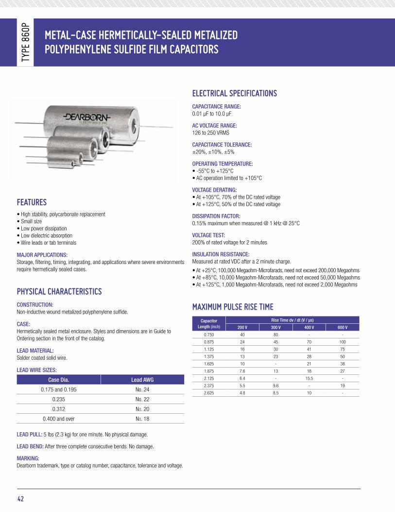
Metal-Case HerMetiCally-sealed Metalized PolyPHeNyleNe sUlFide FilM CaPaCitors
Type
860
p
42
eleCtriCal sPeCiFiCatioNsCapaCitanCe range: 0.01 μF to 10.0 μF
aC VOltage range: 126 to 250 VRMS
CapaCitanCe tOleranCe: ±20%, ±10%, ±5%
Operating temperature: • -55°C to +125°C• AC operation limited to +105°C
VOltage Derating:• At +105°C, 70% of the DC rated voltage • At +125°C, 50% of the DC rated voltage
DissipatiOn FaCtOr: 0.15% maximum when measured @ 1 kHz @ 25°C
VOltage test: 200% of rated voltage for 2 minutes
insulatiOn resistanCe:Measured at rated VDC after a 2 minute charge.
• At +25°C, 100,000 Megaohm-Microfarads, need not exceed 200,000 Megaohms• At +85°C, 10,000 Megaohm-Microfarads, need not exceed 50,000 Megaohms• At +125°C, 1,000 Megaohm-Microfarads, need not exceed 2,000 Megaohms
MaXiMUM PUlse rise tiMeCapacitor
length (inch)
rise time dv / dt (V / μs)
200 V 300 V 400 V 600 V
0.750 40 80 - -
0.875 24 45 70 100
1.125 16 30 41 75
1.375 13 23 28 50
1.625 10 - 21 38
1.875 7.6 13 18 27
2.125 6.4 - 15.5 -
2.375 5.5 9.6 - 19
2.625 4.8 8.5 10 -
FeatUres• High stability, polycarbonate replacement• Small size• Low power dissipation• Low dielectric absorption• Wire leads or tab terminals
majOr appliCatiOns:Storage, filtering, timing, integrating, and applications where severe environments require hermetically sealed cases.
PHysiCal CHaraCteristiCsCOnstruCtiOn:Non-inductive wound metalized polyphenylene sulfide.
Case:Hermetically sealed metal enclosure. Styles and dimensions are in Guide to Ordering section in the front of the catalog.
leaD material:Solder coated solid wire.
leaD Wire sizes:
Case Dia. lead aWg
0.175 and 0.195 No. 24
0.235 No. 22
0.312 No. 20
0.400 and over No. 18
leaD pull: 5 lbs (2.3 kg) for one minute. No physical damage.
leaD BenD: After three complete consecutive bends. No damage.
marking:Dearborn trademark, type or catalog number, capacitance, tolerance and voltage.

43
Metal-Case HerMetiCally-sealed Metalized PolyPHeNyleNe sUlFide FilM CaPaCitors
Type
860
p
staNdard ratiNGs
CapacitanceVoltage Code 200
200 VDC / 126 VaC*Voltage Code 300
300 VDC / 180 VaC*Voltage Code 400
400 VDC / 220 VaC*Voltage Code 600
600 VDC / 250 VaC*μF Code D l D l D l D l
0.010 103 0.174 0.750 0.235 0.750 0.312 0.875 0.312 0.8750.015 153 0.193 0.750 0.312 0.875 0.312 0.875 0.400 1.1250.022 223 0.235 0.750 0.312 0.875 0.312 0.875 0.400 1.1250.033 333 0.235 0.750 0.312 0.875 0.312 1.125 0.400 1.1250.047 473 0.312 0.875 0.312 0.875 0.312 1.125 0.400 1.3750.068 683 0.312 0.875 0.312 1.125 0.400 1.125 0.562 1.1250.10 104 0.312 0.875 0.400 1.125 0.400 1.375 0.562 1.3750.15 154 0.312 1.125 0.400 1.375 0.500 1.125 0.562 1.6250.22 224 0.400 0.875 0.500 1.125 0.562 1.375 0.670 1.6250.33 334 0.400 1.125 0.562 1.125 0.562 1.625 0.750 1.8750.47 474 0.400 1.375 0.562 1.375 0.670 1.625 0.750 2.3750.68 684 0.562 1.125 0.562 1.875 0.670 1.875 1.000 1.8751.00 105 0.562 1.375 0.670 1.875 0.750 2.125 1.000 2.3752.00 205 0.670 1.625 0.750 2.375 1.000 2.125 - -2.50 255 0.670 1.875 0.750 2.625 1.000 2.625 - -3.00 305 0.750 1.875 1.000 1.875 - - - -4.00 405 0.750 2.125 1.000 2.375 - - - -5.00 505 0.750 2.375 - - - - - -6.00 605 1.000 1.875 - - - - - -7.00 705 1.000 1.875 - - - - - -
10.00 106 1.000 2.625 - - - - - -
Additional capacitance values, voltages, and tolerances are available upon request.
* AC voltage rating is at 400Hz. 1.4 x VRMS + VDC should not exceed the rated VDC.
* Graphs of AC voltage vs. frequency follow.
* The dimensions tabulated above are for styles 02, 04, and 13. Subtract 0.062” from the length for styles 01, 03, and 12.
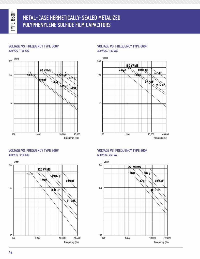
Metal-Case HerMetiCally-sealed Metalized PolyPHeNyleNe sUlFide FilM CaPaCitors
Type
860
p
44
VOltage Vs. FreQuenCY tYpe 860p 200 VDC / 126 VaC
VOltage Vs. FreQuenCY tYpe 860p 400 VDC / 220 VaC
VOltage Vs. FreQuenCY tYpe 860p 300 VDC / 180 VaC
VOltage Vs. FreQuenCY tYpe 860p 600 VDC / 250 VaC
126 VRMS
VRMS
10
1100 1,000 40,00010,000
VOLTAGE vs FREQUENCY TYPE 860P200VDC\126VAC
300
100 10.0 µF
1.0 µF0.47 µF 0.1µF
0.047 µF
5.0 µF 0.01 µF
180 VRMS
VRMS
10
1100 1,000 40,00010,000
VOLTAGE vs FREQUENCY TYPE 860P300VDC\180VAC
300
100
0.10 µF
1.0 µF
0.47 µF
0.047 µF4.0 µF0.01 µF
220 VRMS
VRMS
100
10100 1,000 10,000 40,000
VOLTAGE vs FREQUENCY TYPE 860P400VDC\220VAC
300
0.47µF
1.0 µF0.047 µF
0.01µF
0.10µF
2.5 µF
250 VRMS
VRMS
100
10100 1,000 10,000 40,000
VOLTAGE vs FREQUENCY TYPE 860P600VDC\250VAC
300
.47 µF
1.0 µF 0.047 µF
0.01 µF
0.10 µF
Frequency (Hz) Frequency (Hz)
Frequency (Hz) Frequency (Hz)
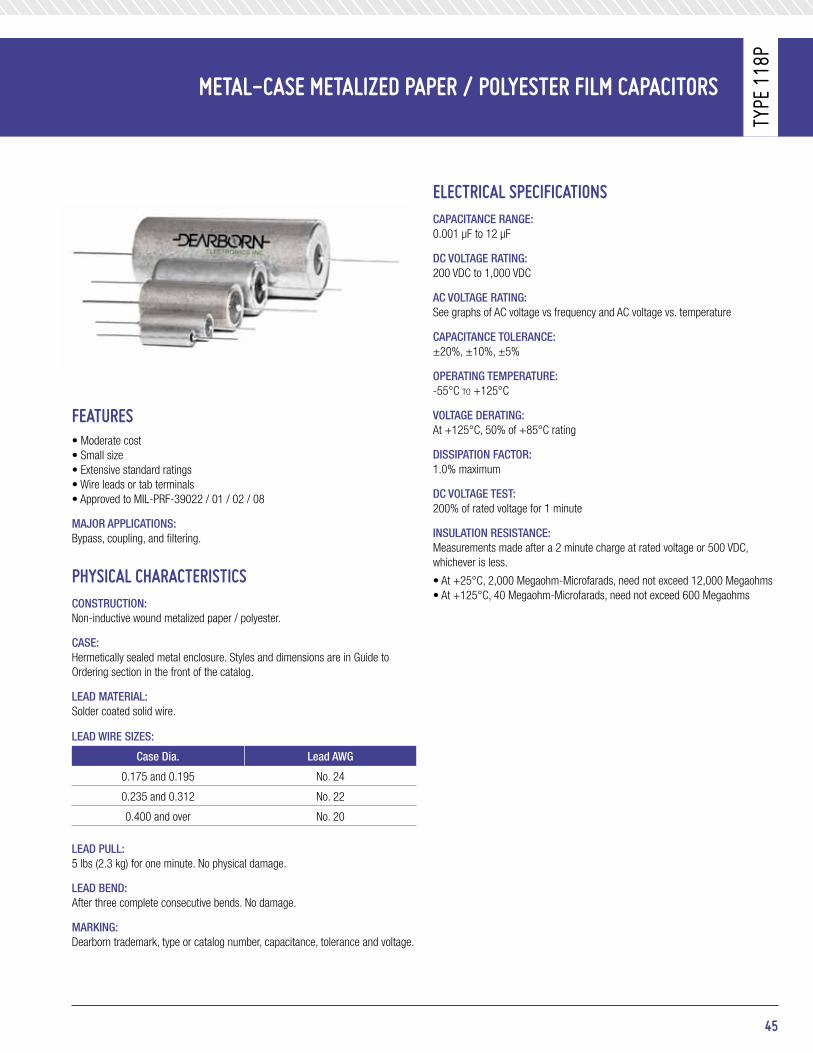
45
Metal-Case Metalized PaPer / Polyester FilM CaPaCitors
Type
118
p
eleCtriCal sPeCiFiCatioNsCapaCitanCe range: 0.001 μF to 12 μF
DC VOltage rating: 200 VDC to 1,000 VDC
aC VOltage rating: See graphs of AC voltage vs frequency and AC voltage vs. temperature
CapaCitanCe tOleranCe: ±20%, ±10%, ±5%
Operating temperature: -55°C to +125°C
VOltage Derating: At +125°C, 50% of +85°C rating
DissipatiOn FaCtOr: 1.0% maximum
DC VOltage test: 200% of rated voltage for 1 minute
insulatiOn resistanCe:Measurements made after a 2 minute charge at rated voltage or 500 VDC, whichever is less.
• At +25°C, 2,000 Megaohm-Microfarads, need not exceed 12,000 Megaohms• At +125°C, 40 Megaohm-Microfarads, need not exceed 600 Megaohms
FeatUres• Moderate cost• Small size• Extensive standard ratings• Wire leads or tab terminals• Approved to MIL-PRF-39022 / 01 / 02 / 08
majOr appliCatiOns:Bypass, coupling, and filtering.
PHysiCal CHaraCteristiCsCOnstruCtiOn:Non-inductive wound metalized paper / polyester.
Case:Hermetically sealed metal enclosure. Styles and dimensions are in Guide to Ordering section in the front of the catalog.
leaD material:Solder coated solid wire.
leaD Wire sizes:
Case Dia. lead aWg
0.175 and 0.195 No. 24
0.235 and 0.312 No. 22
0.400 and over No. 20
leaD pull: 5 lbs (2.3 kg) for one minute. No physical damage.
leaD BenD: After three complete consecutive bends. No damage.
marking:Dearborn trademark, type or catalog number, capacitance, tolerance and voltage.

Metal-Case Metalized PaPer / Polyester FilM CaPaCitorsTy
pe 1
18p
staNdard ratiNGs
CapacitanceVoltage Code 200
200 VDCVoltage Code 400
400 VDCVoltage Code 600
600 VDCVoltage Code 1k0
1,000 VDCμF Code D l D l D l D l
0.0010 102 0.174 0.750 0.235 0.750 0.235 0.750 0.400 0.7500.0015 153 0.174 0.750 0.235 0.750 0.235 0.750 0.400 0.7500.0022 222 0.174 0.750 0.235 0.750 0.235 0.750 0.400 0.7500.0033 332 0.174 0.750 0.235 0.750 0.235 0.750 0.400 0.7500.0047 472 0.174 0.750 0.312 0.875 0.312 0.875 0.400 0.7500.0068 682 0.174 0.750 0.312 0.875 0.312 0.875 0.400 0.7500.010 103 0.174 0.750 0.312 0.875 0.312 0.875 0.400 0.8750.015 153 0.193 0.750 0.312 0.875 0.312 0.875 0.400 0.8750.022 223 0.235 0.750 0.312 0.875 0.312 1.125 0.400 1.1250.033 333 0.235 0.750 0.312 1.125 0.312 1.125 0.400 1.1250.047 473 0.312 0.875 0.400 1.125 0.400 1.125 0.500 1.1250.068 683 0.312 0.875 0.400 1.125 0.400 1.125 0.500 1.1250.10 104 0.312 0.875 0.500 1.125 0.500 1.125 0.562 1.1250.15 154 0.312 1.125 0.500 1.125 0.562 1.125 0.562 1.1250.22 224 0.400 0.875 0.562 1.375 0.562 1.375 0.670 1.6250.33 334 0.400 1.125 0.562 1.625 0.562 1.625 0.670 1.8750.47 474 0.500 1.125 0.670 1.625 0.670 1.625 0.750 1.8750.68 684 0.500 1.125 0.670 1.875 0.670 1.875 1.000 1.8751.00 105 0.562 1.125 0.750 1.875 1.000 1.875 1.000 2.1251.50 155 0.562 1.625 1.000 1.875 1.000 1.875 1.000 2.6252.00 205 0.670 1.625 1.000 1.875 1.000 2.125 - -3.00 305 0.670 1.875 1.000 2.625 - - - -4.00 405 0.750 1.875 - - - - - -5.00 505 1.000 1.875 - - - - - -6.00 605 1.000 1.875 - - - - - -8.00 805 1.000 1.875 - - - - - -
10.00 106 1.000 2.375 - - - - - -12.00 126 1.000 2.625 - - - - - -
Additional capacitance values, voltages and tolerances available upon request.
46
eleCtriCal CHaraCteristiCs Vs. teMPeratUreELECTRICAL CHARACTERISTICS VS TEMPERATURE
+1405+52+52-05-55- 0 +75 +85 +100 +125
Capacitance Change Envelope for 95% Confidence Level
% C
apat
ican
ce C
hang
e -
1,00
0Hz
Temperature (°C)
+10
+8
+6
+4
+2
-0
-2
-4
-6
-8
-10
+12
05+52+52-05-55- 0 +75 +85 +100 +125
% P
ower
Fac
tor
Temperature (°C)
2.0
1.5
1.0
0.5
0
1000 CYCLESTYPICAL
60 CYCLES
ELECTRICAL CHARACTERISTICS VS TEMPERATURE
+1405+52+52-05-55- 0 +75 +85 +100 +125
Capacitance Change Envelope for 95% Confidence Level
% C
apat
ican
ce C
hang
e -
1,00
0Hz
Temperature (°C)
+10
+8
+6
+4
+2
-0
-2
-4
-6
-8
-10
+12
05+52+52-05-55- 0 +75 +85 +100 +125
% P
ower
Fac
tor
Temperature (°C)
2.0
1.5
1.0
0.5
0
1000 CYCLESTYPICAL
60 CYCLES

47
Metal-Case Metalized PaPer / Polyester FilM CaPaCitors
Type
118
p
aC VoltaGe ratiNGs Vs. teMPeratUreaC VOltage ratings at 400hz anD 85°C amBient
aC VOltage ratings at 400hz anD 125°C amBient
aC VOltage ratings at 400hz anD 105°C amBient
AC VOLTAGE RATINGS VS TEMPERATURE
AC VOLTAGE VS FREQUENCY
300
200
100
00.01 0.1 1.0 10
A-C VOLTAGE RATINGS AT 400 HERTZ AND 85 C AMBIENT
Capacitance in Microfarads
Rate
d Vo
ltage
(Rm
s)
Rate
d Vo
ltage
(Rm
s)
Rate
d Vo
ltage
(Rm
s)
1000 V400 V, 600 V200 V
300
200
100
00.01 0.1 1.0 10
A-C VOLTAGE RATINGS AT 400 HERTZ AND 105 C AMBIENT
Capacitance in Microfarads
1000 V400 V, 600 V200 V
300
200
100
00.01 0.1 1.0 10
A-C VOLTAGE RATINGS AT 400 HERTZ AND 125 C AMBIENT
Capacitance in Microfarads
1000 V400 V, 600 V200 V
150
100
50
0.100.01 10.01.0
A-C RATINGS AT 1000 Hz
Capacitance (µF)
Rms
Volta
ge
150
100
50
0.100.01 10.01.0Capacitance (µF)
Rms
Volta
ge
150
100
50
0.100.01 10.01.0Capacitance (µF)
Rms
Volta
ge
1000 V DC400 V, 600 V DC200 V DC1000 V DC400 V, 600 V DC200 V DC
1000 V DC400 V, 600 V DC200 V DC
A-C RATINGS AT 2000 Hz
A-C RATINGS AT 2500 Hz
aC VoltaGe ratiNGs Vs. FreqUeNCyaC ratings at 1,000hz
aC ratings at 2,500hz
aC ratings at 2,000hz
AC VOLTAGE RATINGS VS TEMPERATURE
AC VOLTAGE VS FREQUENCY
300
200
100
00.01 0.1 1.0 10
A-C VOLTAGE RATINGS AT 400 HERTZ AND 85 C AMBIENT
Capacitance in Microfarads
Rate
d Vo
ltage
(Rm
s)
Rate
d Vo
ltage
(Rm
s)
Rate
d Vo
ltage
(Rm
s)
1000 V400 V, 600 V200 V
300
200
100
00.01 0.1 1.0 10
A-C VOLTAGE RATINGS AT 400 HERTZ AND 105 C AMBIENT
Capacitance in Microfarads
1000 V400 V, 600 V200 V
300
200
100
00.01 0.1 1.0 10
A-C VOLTAGE RATINGS AT 400 HERTZ AND 125 C AMBIENT
Capacitance in Microfarads
1000 V400 V, 600 V200 V
150
100
50
0.100.01 10.01.0
A-C RATINGS AT 1000 Hz
Capacitance (µF)
Rms
Volta
ge
150
100
50
0.100.01 10.01.0Capacitance (µF)
Rms
Volta
ge
150
100
50
0.100.01 10.01.0Capacitance (µF)
Rms
Volta
ge
1000 V DC400 V, 600 V DC200 V DC1000 V DC400 V, 600 V DC200 V DC
1000 V DC400 V, 600 V DC200 V DC
A-C RATINGS AT 2000 Hz
A-C RATINGS AT 2500 Hz

Metal-Case sUbMiNiatUre 10 aMPere tHrU-Pass PaPer CaPaCitors
Type
103
p
eleCtriCal sPeCiFiCatioNsCapaCitanCe range: 0.001 μF to 1.0 μF
DC VOltage range: 200 VDC to 600 VDC
CapaCitanCe tOleranCe: ±20%, ±10%
Operating temperature: -55°C to +125°C
VOltage Derating: At +125°C, 50% of the 85°C rating
DissipatiOn FaCtOr: 1.0% maximum
VOltage test: 200% of rated voltage for 2 minutes
insulatiOn resistanCe: Measure at rated voltage, not to exceed 500 VDC, after a 2 minute charge.
• At +25°C, 20,000 Megohm-Microfarads, need not exceed 30,000 Megaohms • At +85°C, 200 Megohm-Microfarads, need not exceed 300 Megaohms
DC resistanCe: 0.01 ohms maximum
insertiOn lOss: See table on next page
CirCUit diaGraM
diMeNsioNs (in inches)
FeatUres• Bulkhead mounting• Excellent RFI specs• Hermetically encased• Low inductance connection• Low insertion loss• Approved to MIL-PRF-11693 / 07• 10 Amp current ratings
majOr appliCatiOns:Used to suppress RF interference in the following equipment, rotatingmachinery, ignition systems, electromechanical devices, and electronic device.
PHysiCal CHaraCteristiCsCOnstruCtiOn:Non-inductive wound paper / foil, wound around a feed-thru bus. The case is the common ground of the three terminal network.
Case:Hermetically sealed metal enclosure; the case and terminal styles are shown above.
leaD pull: 5 lbs (2.3 kg) for one minute. No physical damage.
leaD / BenD: After three complete consecutive bends. No damage.
marking: Dearborn trademark, type or catalog number, capacitance, tolerance and voltage.
48
NUT 5/16-24UNF-2APT. NO. 6-113
0.125±0.015
EXTERNAL TOOTHEDLOCKWASHERPT. NO. 2-1230.040 DIA.
+0.004-0.001
(10 .18 AWG)SOLID TINNED LEADS
1.625
+1.000-0.000 ±0.031
±0.0310.312
+0.015-0.005
0.125MAXDIA.
1.625
+1.000-0.000
L
D
CL
CL
0.020 ±0.005
0.125±0.015
SLOT 0.062 x 0.125
0.1560.296
±0.062
±0.0150.187 ±0.015
0.020±0.005
CL
CLSLOT x 0.125
0.312 ± 0.031
0.296 ± 0.062
-24 UNF - 2A THD5
16
0.156 ±0.015 0.187 ±0.015
0.0600.050
0.2550.250
ACROSSFLATS
0.125 ±0.015

staNdard ratiNGs
μFCatalog no.* inches millimeters
tab. term Wire lead D l D l200 VDC
0.047 103P473X0200T 103P473X0200S 0.400 0.875 10.16 22.230.10 103P104X0200T 103P104X0200S 0.400 1.125 10.16 28.580.22 103P224X0200T 103P224X0200S 0.562 1.125 14.27 28.580.47 103P474X0200T 103P474X0200S 0.562 1.875 14.27 47.531.00 103P105X0200T 103P105X0200S 0.750 2.125 19.05 53.96
300 VDC0.047 103P473X0300T 103P473X0300S 0.400 1.125 10.16 28.580.10 103P104X0300T 103P104X0300S 0.400 1.375 10.16 34.830.22 103P224X0300T 103P224X0300S 0.562 1.375 14.27 34.830.47 103P474X0300T 103P474X0300S 0.670 1.875 17.02 47.83
400 VDC0.047 103P473X0400T 103P473X0400S 0.400 1.375 10.16 34.930.10 103P104X0400T 103P104X0400S 0.562 1.125 14.27 28.580.22 103P224X0400T 103P224X0400S 0.562 1.875 14.27 47.830.47 103P474X0400T 103P474X0400S 0.750 2.125 19.05 53.98
600 VDC0.0010 103P102X0600T 103P102X0600S 0.400 0.750 10.16 19.050.0047 103P472X0600T 103P472X0600S 0.400 0.750 10.16 19.050.010 103P103X0600T 103P103X0600S 0.400 0.750 10.16 19.050.047 103P473X0600T 103P473X0600S 0.400 1.375 10.16 34.930.10 103P104X0600T 103P104X0600S 0.562 1.375 14.27 34.930.22 103P224X0600T 103P224X0600S 0.670 1.875 17.02 47.83.0.47 103P474X0600T 103P474X0600S 0.750 2.375 19.05 60.32
*The catalog numbers given are for capacitance tolerance of ± 20%. To specify ± 10% tolerance, change X0 to X9. Mounting hardware furnished unassembled.
49
Metal-Case sUbMiNiatUre 10 aMPere tHrU-Pass PaPer CaPaCitors
Type
103
p
eleCtriCal CHaraCteristiCs Vs. teMPeratUre iNsertioN loss CHaraCteristiCs For ideal CaPaCitors
These capacitors are designed to meet all the electrical, mechanical, and environmental requirements of Military Specification MIL-PRF-11693. The insertion loss of such capacitors is defined by this military specification as follows. “...the insertion loss shall be not more than 6 decibels (dB) permissible dips below the value shown on the graph above for an ideal capacitor of the same nominal capacitance value, when tested at frequencies from 0.15 megahertz (MHz) up to that frequency at which the insertion loss of the capacitor under test becomes 60 dB; at all higher frequencies, up to 1,000MHz, the insertion loss shall not fall below 60 dB. Deviations in the nature of dips in the curve will be permitted; such dips indicate a drop in insertion loss below that of an ideal capacitor followed by a rise in insertion loss, as frequency is increased, faster than the rise that is characteristic of an ideal capacitor. Such dips are characteristic of all extended foil capacitors.”
+4
05+52+52-55- 0 +75 +85 +100 +125
Capacitance Change Envelope For 95% Confidence Level
% C
apat
ican
ce C
hang
e -
1000
Hz
Temperature (°C)
0
-2
-4-6
-8
+2
05+52+52-55- 0 +75 +85 +100 +125
% D
issi
patio
n Fa
ctor
- 1
000H
z
Temperature (°C)
2.5
2.0
1.5
1.0
0.5
0
TYPICAL
101.0 1.0 1,000100
Inse
rtion
Los
s (d
B) 40
50
60
70
30
20
10
0
2.0 µF
1.0 µF
0.47 µF
0.22 µF
0.1 µF
0.047 µF
0.022 µF
0.01 µF
0.0047 µF
0.0022 µF
0.001 µF
Frequency (MHz)
+4
05+52+52-55- 0 +75 +85 +100 +125
Capacitance Change Envelope For 95% Confidence Level
% C
apat
ican
ce C
hang
e -
1000
Hz
Temperature (°C)
0
-2
-4-6
-8
+2
05+52+52-55- 0 +75 +85 +100 +125
% D
issi
patio
n Fa
ctor
- 1
000H
z
Temperature (°C)
2.5
2.0
1.5
1.0
0.5
0
TYPICAL

PaPer / Polyester dieleCtriCeXteNded Foil eleCtrodes
Type
131
p
eleCtriCal sPeCiFiCatioNsCapaCitanCe range: 0.001 μF to 1.0 μF
VOltage rating: 200 VDC to 1,000 VDC
CapaCitanCe tOleranCe: ±20%, ±10%, ±5%
Operating temperature: -65°C to +125°C
VOltage Derating: At +125°C, 50% of the 85°C rating
DissipatiOn FaCtOr: 1.0% maximum
DC VOltage test: 200% of rated voltage for 2 minutes
insulatiOn resistanCe:Measure at rated VDC or 500 V, whichever is less, after a 2 minute charge.
• At +25°C, 20,000 Megaohm-Microfarads, need not exceed 30,000 Megaohms• At +125°C, 20 Megaohm-Microfarads, need not exceed 250 Megaohms
MaXiMUM PUlse rise tiMeCapacitor
length (inch)
rise time dv / dt (V / μs)
200 VDC 400 VDC 600 VDC 1,000 VDC
0.750 1600 1600 4500 -
0.875 1000 1400 1500 2500
1.125 500 800 1000 1500
1.375 350 500 800 1000
1.625 250 350 500 800
1.875 - - - 550
2.125 200 300 400 500
2.375 - - 300 450
FeatUres• Moderate cost• Small size• High peak current ratings• High corona starting voltage• Approved to MIL-PRF-19978
majOr appliCatiOns:High voltage, high current, high pulse operations, protection circuits, and snubber applications.
PHysiCal CHaraCteristiCsCOnstruCtiOn:Non-inductive wound paper / polyester dielectric with extended foil electrodes. Impregnated with vitamin Q.
Case:Hermetically sealed metal enclosure. Styles and dimensions are in Guide to Ordering section in the front of the catalog.
leaD material:Solder coated solid wire.
leaD Wire sizes:
Case Dia. lead aWg
0.235 and 0.312 No. 22
0.400 and over No. 20
leaD pull:5 lbs (2.3 kg) for one minute. No physical damage.
leaD BenD:After three complete consecutive bends. No damage.
marking:Dearborn trademark, type or catalog number, capacitance, tolerance, and voltage.
50

staNdard ratiNGs
CapacitanceVoltage Code 200
200 VDCVoltage Code 400
400 VDCVoltage Code 600
600 VDCVoltage Code 1k0
1,000 VDCμF Code D l D l D l D l
0.0010 102 - - - - 0.235 0.750 0.400 0.8750.0015 152 - - - - 0.235 0.750 0.400 0.8750.0022 222 - - - - 0.235 0.750 0.400 0.8750.0033 332 - - 0.235 0.750 0.312 0.875 0.400 0.8750.0047 472 0.235 0.750 0.235 0.750 0.312 0.875 0.400 0.8750.0068 682 0.235 0.750 0.235 0.750 0.312 0.875 0.400 0.8750.010 103 0.235 0.750 0.235 0.750 0.312 0.875 0.400 0.8750.015 153 0.312 0.875 0.312 0.875 0.400 0.875 0.400 1.1250.022 223 0.312 0.875 0.400 0.875 0.400 0.875 0.400 1.3750.033 333 0.312 0.875 0.400 0.875 0.400 1.125 0.562 1.1250.047 473 0.400 0.875 0.400 1.125 0.400 1.375 0.562 1.3750.068 683 0.400 0.875 0.400 1.375 0.562 1.125 0.562 1.6250.10 104 0.400 1.125 0.562 1.125 0.562 1.375 0.670 1.6250.15 154 0.400 1.375 0.562 1.375 0.562 1.625 0.670 1.8750.22 224 0.562 1.125 0.562 1.625 0.670 1.625 0.750 2.1250.33 334 0.562 1.375 0.670 1.625 0.750 2.125 1.000 2.1250.47 474 0.562 1.625 0.750 2.125 0.750 2.375 1.000 2.3750.68 684 0.670 1.625 - - - - - -1.00 105 0.750 2.125 - - - - - -
Additional capacitance values, voltages, and tolerances are available upon request.
* The dimensions shown are for style 02. The dimensions for other styles are included in the general section in the front of the catalog.
51
PaPer / Polyester dieleCtriCeXteNded Foil eleCtrodes
Type
131
p

PaPer / Polyester dieleCtriCeXteNded Foil eleCtrodes
Type
132
p
eleCtriCal sPeCiFiCatioNsCapaCitanCe range: 0.001 μF to 1.0 μF
VOltage rating: 100 VDC to 1,000 VDC
CapaCitanCe tOleranCe: ±20%, ±10%, ±5%
Operating temperature: -65°C to +125°C
VOltage Derating: At +125°C, 50% of the 85°C rating
DissipatiOn FaCtOr: 1.0% maximum
DC VOltage test: 200% of rated voltage for 2 minutes
insulatiOn resistanCe:Measure at rated VDC or 500 V, whichever is less, after a 2 minute charge.
• At +25°C, 20,000 Megaohm-Microfarads, need not exceed 30,000 Megaohms• At +125°C, 20 Megaohm-Microfarads, need not exceed 250 Megaohms
MaXiMUM PUlse rise tiMeCapacitor
length (inch)
rise time dv / dt (V / μs)
100 VDC 200 VDC 300 VDC 400 VDC 600 VDC 1,000 VDC
0.687 / 0.750 800 1600 2000 3000 4500 -
0.812 / 0.875 700 1000 1000 1000 1500 2500
1.062 / 1.125 400 500 650 800 1000 1500
1.312 / 1.375 300 350 425 500 800 1000
1.562 / 1.625 200 250 300 350 500 800
1.812 / 1.875 - - - - - 550
2.062 / 2.125 - 200 250 300 400 500
2.312 / 2.375 - - - - 300 450
FeatUres• Moderate cost• Small size• High peak current ratings• High corona starting voltage• Approved to MIL-PRF-19978
majOr appliCatiOns:High voltage, high current, high pulse operations, protection circuits, and snubber applications.
PHysiCal CHaraCteristiCsCOnstruCtiOn:Non-inductive wound paper / polyester dielectric with extended foil electrodes. Impregnated with vitamin Q.
Case:Hermetically sealed metal enclosure. Styles and dimensions are in Guide to Ordering section in the front of the catalog.
leaD material:Solder coated solid wire.
leaD Wire sizes:
Case Dia. lead aWg
< 0.235 No. 24
< 0.235 and 0.312 No. 22
0.400 and over No. 20
leaD pull:5 lbs (2.3 kg) for one minute. No physical damage.
leaD BenD:After three complete consecutive bends. No damage.
marking:Dearborn trademark, type or catalog number, capacitance, tolerance, and voltage.
52
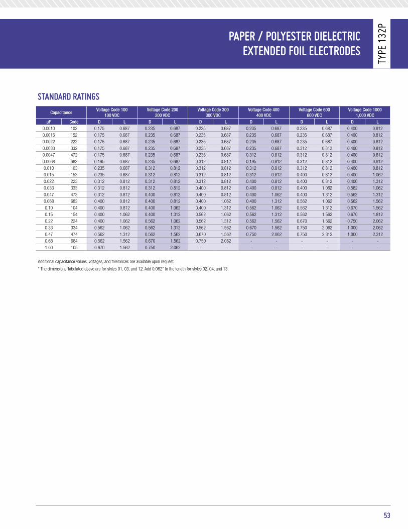
staNdard ratiNGs
CapacitanceVoltage Code 100
100 VDCVoltage Code 200
200 VDCVoltage Code 300
300 VDCVoltage Code 400
400 VDCVoltage Code 600
600 VDCVoltage Code 1000
1,000 VDCμF Code D l D l D l D l D l D l
0.0010 102 0.175 0.687 0.235 0.687 0.235 0.687 0.235 0.687 0.235 0.687 0.400 0.8120.0015 152 0.175 0.687 0.235 0.687 0.235 0.687 0.235 0.687 0.235 0.687 0.400 0.8120.0022 222 0.175 0.687 0.235 0.687 0.235 0.687 0.235 0.687 0.235 0.687 0.400 0.8120.0033 332 0.175 0.687 0.235 0.687 0.235 0.687 0.235 0.687 0.312 0.812 0.400 0.8120.0047 472 0.175 0.687 0.235 0.687 0.235 0.687 0.312 0.812 0.312 0.812 0.400 0.8120.0068 682 0.195 0.687 0.235 0.687 0.312 0.812 0.195 0.812 0.312 0.812 0.400 0.8120.010 103 0.235 0.687 0.312 0.812 0.312 0.812 0.312 0.812 0.312 0.812 0.400 0.8120.015 153 0.235 0.687 0.312 0.812 0.312 0.812 0.312 0.812 0.400 0.812 0.400 1.0620.022 223 0.312 0.812 0.312 0.812 0.312 0.812 0.400 0.812 0.400 0.812 0.400 1.3120.033 333 0.312 0.812 0.312 0.812 0.400 0.812 0.400 0.812 0.400 1.062 0.562 1.0620.047 473 0.312 0.812 0.400 0.812 0.400 0.812 0.400 1.062 0.400 1.312 0.562 1.3120.068 683 0.400 0.812 0.400 0.812 0.400 1.062 0.400 1.312 0.562 1.062 0.562 1.5620.10 104 0.400 0.812 0.400 1.062 0.400 1.312 0.562 1.062 0.562 1.312 0.670 1.5620.15 154 0.400 1.062 0.400 1.312 0.562 1.062 0.562 1.312 0.562 1.562 0.670 1.8120.22 224 0.400 1.062 0.562 1.062 0.562 1.312 0.562 1.562 0.670 1.562 0.750 2.0620.33 334 0.562 1.062 0.562 1.312 0.562 1.562 0.670 1.562 0.750 2.062 1.000 2.0620.47 474 0.562 1.312 0.562 1.562 0.670 1.562 0.750 2.062 0.750 2.312 1.000 2.3120.68 684 0.562 1.562 0.670 1.562 0.750 2.062 - - - - - -1.00 105 0.670 1.562 0.750 2.062 - - - - - - - -
Additional capacitance values, voltages, and tolerances are available upon request.
* The dimensions Tabulated above are for styles 01, 03, and 12. Add 0.062” to the length for styles 02, 04, and 13.
53
PaPer / Polyester dieleCtriCeXteNded Foil eleCtrodes
Type
132
p

batHtUb style Metal Case PaPer / Polyester Foil CaPaCitors
Type
Cp5
3/54
/55
VOltage Derating:• Characteristics E and F at +85°C, 65% of rated voltage• Characteristic K at +125°C, 70% of rated voltage
DissipatiOn FaCtOr:1.0% maximum
diMeNsioNs (in inches)
FeatUres• Capacitance values to 10 μF• Drawn metal “bathtub” cases• Top, side, or bottom terminals• Approved to MIL- C- 25
majOr appliCatiOns:Bypass, coupling, filtering.
PHysiCal CHaraCteristiCsCOnstruCtiOn:Non-inductive wound paper / polyester film with extended foil electrodes.
Case:Hermetically sealed metal enclosure.
terminals: sYmBOl BGlass to metal solder-seal with non removable solder lug.
marking:Dearborn trademark, type number, capacitance, tolerance, voltage, and date code.
eleCtriCal sPeCiFiCatioNsCapaCitanCe range: 0.05 μF to 10.0 μF
DC VOltage rating: 100 VDC to 1,000 VDC
CapaCitanCe tOleranCe: • K, ±10% • V, +20 -10%
Operating temperature: • Characteristics E and F -55°C to +85°C • Characteristic K -55°C to +125°C
54
0.188 ± 0.016Dia. Holes
CLCLCL
1 3 2
0.75 Max.
0.375 ± 0.031
See notes 3 & 7
1.062 ± 0.094
1.687 Max.
E
D
A
C
B
0.025 - 0.005+ 0.15
0.562 Dia.Max.
0.188 ± 0.016 Dia. Holes
CL
CL
1 3 2
0.75 Max.
0.375± 0.031
See notes 3 & 7
1.062 ± 0.094
1.687 Max.
E
D
A C
B
0.025 + 0.15- 0.005
0.562 Max. Dia.
0.188 ± 0.016 Dia. Holes
CL
1 3 2
0.75 Max.
0.375 ± 0.031
See notes 3 & 7
1.062 ± 0.0941.687 Max.
E
D
A
C
B
0.025 + 0.15- 0.005
0.562 Max. Dia.
tYpe Cp53
tYpe Cp54
tYpe Cp55
note:
1. See following tables for additional dimensions.2. All dimensions in inches.3. Terminals need not be identified by numbers as shown. Shape of terminals and terminal lugs (drilled, punched, forked, or slotted) optional.4. Mounting holes may be elongated.5. For circuit 1, use terminals 1 and 2. For circuit 2, use terminal 1. For circuit 4, use terminal 1 for common connection and identify common
terminal by the letter C on case adjacent to terminal. For circuit 6, use terminals 1 and 2.6. Capacitors differ only in location of terminals. Style CP53, having the terminals on one side, contains certain values of capacitance in a smaller
case than is possible with styles CP54 and CP55, the terminals of which are on top and bottom faces respectively.7. Terminal lugs shall be oriented as shown with respect to side of case bearing terminal identification numbers.

Type
Cp5
3/54
/55
dieleCtriC WitHstaNdiNG VoltaGe test
Circuit symbol Circuit diagram test test connectionstest Voltage
(Percent of Rated DC Voltage)time test applied
(Minutes)
1
Terminal to terminal 1 to 2 200 1 / 1 2 /
Terminal to case 1 and 2 to case400 5 / 1 3 / 4 /
200 + 1,000 6 / V 1 3 / 4 /
2 Terminal to terminal 1 to case 200 1 / 1 2 /
4Terminal to terminal 1 to 2 and 3 together 200 1 / 1 7 /
Terminal to case 1, 2, and 3 to case 200 + 1,000 V 1 3 / 4 /
5
Terminal to case 1, 2, and 3 to case 200 1 7 /
Terminal to terminal1 and 2 to 3
1 to 2200 1 7 /
6 Terminal to terminal1 and 2 to case 200 1 7 /
1 to 2 200 1 7 /
1 / 175 percent of rated de voltage after temperature-and immersion-cycling and moisture resistance tests.2 / For quality conformance inspection and at the option of the supplier, either 200 percent of rated de voltage for not less than 15 seconds or 250 percent of rated voltage for not less than 1 second.3 / For quality contformance inspection, the period of test voltage application shall be 1 second.4 / For quality conformance inspection, applications may be made between each terminal individually and the case, at the option of the supplier.5 / For capacitors having dc voltage ratings of 600 V and less.6 / For capacitors having dc voltage ratings greater than 600 V.7 / For quality conformance inspection, the application may be made for 1 second if the capacitor has passed group A inspection.
terMiNal to terMiNal iNsUlatioN resistaNCe MeasUreMeNts
Capacitance valuesminimum insulation resistance 1 /
Characteristic e Characteristic F Characteristic k
0.33 microfarads and lessgreater than 0.33 microfarads
At 25°C6,000 megaohms2,000 megaohm 2 /
At 25°C4,500 megaohms
1500 megaohm microfarads 2 /
At 25°C18,000 megaohms
6,000 megaohm microfarads 2 /
greater than 0.033 microfaradsAt 85°C
20 megaohm microfarads 2 /
At 85°C15 megaohm microfarads 2 / -
0.067 microfarads and lessGreater than 0.67 microfarads
- -At 125°C
150 megaohms10 megaohm microfarads 2 /
1 / A potential equal to the DC rated voltage or 500 VDC, whichever is less shall be applied.2 / Product obtained by multiplying the capacitance in microfarads by the insulation resistance in megaohms.
55
batHtUb style Metal Case PaPer / Polyester Foil CaPaCitors

batHtUb style Metal Case PaPer / Polyester Foil CaPaCitors
Type
Cp5
3/54
/55
staNdard ratiNGstype Designa-
tion 1 /
De Voltage rating (see figure 2)
Capacitance μFCapacitance tolerance 2 / Characteristics Vibration grade
Case size
Characteristics e Characteristics F Characteristics kCP5-B-B105K1 100 1 K E, F 1 A2 A1 -CP5-B-EB205K1 100 2 K E 1 B1 - -CP5-B-B405K1 100 4 K E, F 1 C2 C1 -CP5-B-FB805K1 100 8 K F 1 - C1 -CP5-B-FB106K1 100 10 K F 1 - C2 -CP5-B-FC504K1 200 0.5 K F 1 - A1 -CP5-B-EC105K1 200 1 K E 1 B1 - -CP5-B-EC205K1 200 2 K E 1 C1 - -CP5-B-KE503K1 400 0.05 K K 1 - - A1CP5-B-KE104K1 400 0.10 K K 1 - - A1CP5-B-KE254K1 400 0.25 K K 1 - - A1CP5-B-KE504K1 400 0.5 K K 1 - - B1CP5-B-KE105K1 400 1 K K 1 - - B1CP5-B-EF254K1 600 0.25 K E 1 A1 - -CP5-B-F504K1 600 0.5 K E, F 1 A3 A2 -CP5-B-F105K1 600 1 K E, F 1 B2 B1 -CP5-B-EF205K1 600 2 K E 1 C2 3 / - -CP5-B-EG503K1 1,000 0.05 K E 1 A1 - -CP5-B-EG104K1 1,000 0.1 K E 1 A1 - -CP5-B-G254K1 1,000 0.25 K E, F 1 A2 A1 -CP5-B-EG504K1 1,000 0.5 K E 1 B1 - -CP5-B-EG105K1 1,000 1 K E 1 C2 3 / - -CP5-B-EF503V1 600 0.05-0.05 4 / V E 1 A1 - -CP5-B-EF104V1 600 0.1-0.1 V E 1 A1 - -CP5-B-F254V1 600 0.25-0.25 V E, F 1 A3 A2 -CP5-B-F504V1 600 0.5-0.5 V E, F 1 B2 B1 -CP5-B-EF105V1 600 1-1 V E 1 C2 3 / - -CP5-B-EG503V1 1,000 0.05-0.05 V E 1 A1 - -CP5-B-G104V1 1,000 0.1-0.1 V E, F 1 A2 A1 -CP5-B-EG254V1 1,000 0.25-0.25 V E 1 B1 - -CP5-B-EG504V1 1,000 0.5-0.5 V E 1 C2 3 / - -CP5-B5-E504V1 400 0.5-0.5-0.5 V E, F 1 C2 C1 -CP5-B5-F104V1 600 0.1-0.1-0.1 V E, F 1 A2 A1 -CP5-B5EF254V1 600 0.25-0.25-0.25 V E 1 B1 - -CP5-B5EF504V1 600 0.5-0.5-0.5 V E 1 C2 3 / - -CP5-B5EG503V1 1,000 0.05-0.05-0.05 V E 1 A1 - -CP5-B5EG104V1 1,000 0.1 -0.1 -0.1 V E 1 B1 - -CP5-B5EG254V1 1,000 0.25-0.25-0.25 V E 1 C2 3 / - -
1 / Complete type designation shall include additional symbols to complete style designation. Indicate circuit (where applicable) and characteristics (where applicable).2 / Capacitance tolerance in percent: K, ±10; V, +20, -10.3 / For styles CP54 and CP55, case size is C3.4 / For multiple-unit capacitors, the watt-second rating is the sum of the watt-second ratings of the component sections.
Case size a ±0.062 B ±0.062+0.062
C -0.125D ±0.031 e ±0.062
A1 1.812 1.000 0.750 2.125 2.500A2 1.812 1.000 0.875 2.125 2.500A3 1.812 1.000 1.000 2.125 2.500B1 2.000 1.750 0.875 2.375 2.750B2 2.000 1.750 1.000 2.375 2.750C1 2.000 2.000 1.000 2.375 2.750C2 2.000 2.000 1.125 2.375 2.750C3 2.000 2.000 1.250 2.375 2.750
Refer to MIL-C-25 / 4 for additional information.
56

57
Glass tUbUlar HiGH-VoltaGe PaPer / Polyester diFilM® CaPaCitors
Type
205
p
diMeNsioNs (in inches / mm)
FeatUres• Glass case• 2,000 VDC to 10,000 VDC• Two temperature ranges• Long leakage path• High altitude stability• Similar parts approved to MIL-PRF-19978 / 02
majOr appliCatiOns:High voltage applications both at high altitude, and ground level. Power supplies, induction heating equipment, electrostatic precipitators, as well as coupling and bypass applications.
PHysiCal CHaraCteristiCsCOnstruCtiOn:Dielectric-paper / polyester, electrode-aluminum foil either extended or laid in tab. Impregnated with vitamin Q.
Case:Heavy wall tempered glass. Metal ferrules are bonded to the end of the glass and metal end caps are soldered to the ferrules to make a hermetically sealed assembly.
leaD / terminals:Tubes with a diameter of 0.53 inches have 20 AWG leads.Larger tube diameters have 8-32 studs on both ends.
leaD pull: 5 lbs (2.3 kg) for one minute. No physical damage.
leaD BenD: After three complete consecutive bends. No damage.
marking: Dearborn trademark, type or catalog number, capacitance, and voltage.
eleCtriCal sPeCiFiCatioNsCapaCitanCe range: 0.001 μF to 0.5 μF
VOltage rating: 2,000 VDC to 10,000 VDC
CapaCitanCe tOleranCe: ±20%, ±10%
Operating temperature: -55°C to +85°C or -55°C to +125°C
DissipatiOn FaCtOr: 1.0% maximum
±0.060±1.5
1.50038.1 Min.
1.50038.1 Min.
±0.030±0.76
0.032(0.82 mm)
L
Dia. wire (No. 20 AWG)
Inmm
D Dia.
±0.060±1.5
0.375 ±0.0609.5 ±1.5
0.375 ±0.609.5 ±1.5
±0.030±0.76
No. 8-32 NC-2Stud (both ends)
L
Inmm
D Dia.
eleCtriCal CHaraCteristiCs Vs. teMPeratUre
05+52+52-05-55- 0 +75 +85 +100 +105 +125
% C
apat
ican
ce
Temperature (°C)
Temperature (°C)
108
106
104
102
100
98
96
94
Typical
05+52+52-05-55- 0 +75 +85 +100 +105 +125
% D
issi
patio
n Fa
ctor
1.4
1.6
1.8
2.0
1.2
1.0
0.8
0.6
0.4
0.2
0
Typical60Hz
1000Hz
05+52+52-05-55- 0 +75 +85 +100 +105 +125
% C
apat
ican
ce
Temperature (°C)
Temperature (°C)
108
106
104
102
100
98
96
94
Typical
05+52+52-05-55- 0 +75 +85 +100 +105 +125
% D
issi
patio
n Fa
ctor
1.4
1.6
1.8
2.0
1.2
1.0
0.8
0.6
0.4
0.2
0
Typical60Hz
1000Hz
±0.060±1.5
1.50038.1 Min.
1.50038.1 Min.
±0.030±0.76
0.032(0.82 mm)
L
Dia. wire (No. 20 AWG)
Inmm
D Dia.
±0.060±1.5
0.375 ±0.0609.5 ±1.5
0.375 ±0.609.5 ±1.5
±0.030±0.76
No. 8-32 NC-2Stud (both ends)
L
Inmm
D Dia.
DC VOltage test: 175% of rated voltage for 1 minute
insulatiOn resistanCe:Measure at 500 VDC after a 2 minute charge.
• At +25°C, 20,000 Megaohm-Microfarads, need not exceed 100,000 Megaohms• At +85°C, 300 Megaohm-Microfarads, need not exceed 2,000 Megaohms• At +125°C, 20 Megaohm-Microfarads, need not exceed 250 Megaohms

Glass tUbUlar HiGH-VoltaGe PaPer / Polyester diFilM® CaPaCitors
Type
205
p
staNdard ratiNGsstanDarD ratings FOr +85°C OperatiOn stanDarD ratings FOr +125°C OperatiOn
μF Catalog numberinches
Catalog numberinches
D l D l
2,000 VDC0.001 - - - 205P102X92K0SK 0.53 1.190.002 - - - 205P202X92K0SK 0.53 1.190.005 - - - 205P502X92K0SK 0.53 1.190.01 - - - 205P103X92K0SK 0.53 1.190.02 205P203X92K0SE 0.53 1.56 205P203X92K0LK 0.63 1.560.05 205P503X92K0LE 0.75 1..75 205P503X92K0LK 0.75 2.250.10 205P104X92K0LE 0.75 2.25 205P104X92K0LK 1.03 2.250.25 205P254X92K0LE 1.03 2.75 205P254X92K0LK 1.34 3.500.50 205P504X92K0LE 1.34 2.75 - - -
3,000 VDC0.001 - - - 205P102X93K0SK 0.53 1.190.002 - - - 205P202X92K0SK 0.53 1.190.005 205P502X92K0SE 0.53 1.19 205P502X92K0SK 0.53 1.560.01 205P103X92K0SE 0.53 1.56 205P103X93K0LK 0.63 1.560.02 205P203X92K0LE 0.63 2.25 205P203X93K0LK 0.75 1.750.05 205P503X92K0LE 0.75 2.25 205P503X93K0LK 1.03 2.250.10 205P104X92K0LE 1.03 2.25 205P104X93K0LK 1.34 2.750.25 205P254X93K0LE 1.34 2.75 - - -
4,000 VDC0.001 205P102X94K0SE 0.53 1.19 205P102X94K0SK 0.53 1.560.002 205P202X94K0SE 0.53 1.19 205P202X94K0SK 0.53 1.560.005 205P502X94K0SE 0.53 1.56 205P502X94K0LK 0.63 1.560.01 205P103X94K0LE 0.63 1.56 205P103X94K0LK 0.75 1.750.02 205P203X94K0LE 0.75 1.75 205P203X94K0LK 0.75 2.250.05 205P503X94K0LE 0.87 2.25 205P503X94K0LK 1.34 2.750.10 205P104X94K0LE 1.03 2.75 205P104X94K0LK 1.34 2.750.25 205P254X94K0LE 1.34 3.50 - - -
5,000 VDC0.001 - - - 205P102X95K0SK 0.53 1.560.002 - - - 205P202X95K0SK 0.53 1.560.005 205P502X95K0SE 0.53 1.56 205P502X95K0LK 0.63 1.560.01 205P103X95K0LE 0.63 1.56 205P103X95K0LK 0.75 1.750.02 205P203X95K0LE 0.75 1.75 205P203X95K0LK 0.87 2.750.05 205P503X95K0LE 0.87 2.25 205P503X95K0LK 1.34 2.250.10 205P104X95K0LE 1.03 2.75 205P104X95K0LK 1.34 3.50
7,500 VDC0.001 205P102X97K5LE 0.63 2.25 205P102X97K5LK 0.63 2.250.002 205P202X97K5LE 0.63 2.25 205P202X97K5LK 0.75 1.750.005 205P502X97K5LE 0.75 1.75 205P502X97K5LK 0.75 2.250.01 205P103X97K5LE 0.75 2.25 205P103X97K5LK 0.87 2.250.02 205P203X97K5LE 1.03 2.75 205P203X97K5LK 1.34 2.750.03 - - - 205P303X97K5LK 1.34 2.750.05 205P503X97K5LE 1.34 2.75 205P503X97K5LK 1.34 4.250.10 205P104X97K5LE 1.34 3.50 - - -
10,000 VDC0.0001 - - - 205P101X910KLK 0.63 2.250.0002 - - - 205P201X910KLK 0.63 2.250.0005 - - - 205P501X910KLK 0.63 2.250.001 205P102X910KLE 0.63 2.25 205P102X910KLK 0.75 2.250.002 205P202X910KLE 0.63 2.25 205P202X910KLK 0.87 2.250.005 205P502X910KLE 0.75 2.25 205P502X910KLK 1.03 2.750.01 205P103X910KLE 1.03 2.75 205P103X910KLK 1.34 2.750.02 205P203X910KLE 1.34 2.75 205P203X910KLK 1.34 4.250.05 205P503X910KLE 1.34 4.25 - - -
The catalog numbers given are for capacitance tolerance of ± 10%. To specify ± 20% tolerance, change X9 to X0.
58
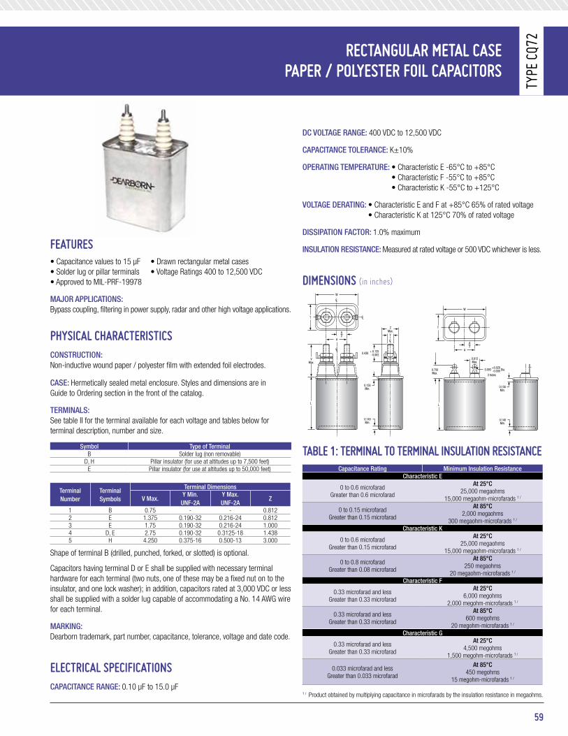
59
reCtaNGUlar Metal CasePaPer / Polyester Foil CaPaCitors
Type
CQ7
2
DC VOltage range: 400 VDC to 12,500 VDC
CapaCitanCe tOleranCe: K±10%
Operating temperature: • Characteristic E -65°C to +85°C • Characteristic F -55°C to +85°C • Characteristic K -55°C to +125°C
VOltage Derating: • Characteristic E and F at +85°C 65% of rated voltage • Characteristic K at 125°C 70% of rated voltage
DissipatiOn FaCtOr: 1.0% maximum
insulatiOn resistanCe: Measured at rated voltage or 500 VDC whichever is less.
diMeNsioNs (in inches)
table 1: terMiNal to terMiNal iNsUlatioN resistaNCeCapacitance rating minimum insulation resistance
Characteristic e
0 to 0.6 microfaradGreater than 0.6 microfarad
at 25°C25,000 megaohms
15,000 megaohm-microfarads 1 /
0 to 0.15 microfaradGreater than 0.15 microfarad
at 85°C2,000 megaohms
300 megaohm-microfarads 1 /
Characteristic k
0 to 0.6 microfaradGreater than 0.15 microfarad
at 25°C25,000 megaohms
15,000 megaohm-microfarads 1 /
0 to 0.8 microfaradGreater than 0.08 microfarad
at 85°C250 megaohms
20 megaohm-microfarads 1 /
Characteristic F
0.33 microfarad and lessGreater than 0.33 microfarad
at 25°C6,000 megohms
2,000 megohm-microfarads 1 /
0.33 microfarad and lessGreater than 0.33 microfarad
at 85°C600 megohms
20 megohm-microfarads 1 /
Characteristic g
0.33 microfarad and lessGreater than 0.33 microfarad
at 25°C4,500 megohms
1,500 megohm-microfarads 1 /
0.033 microfarad and lessGreater than 0.033 microfarad
at 85°C450 megohms
15 megohm-microfarads 1 /
1 / Product obtained by multiplying capacitance in microfarads by the insulation resistance in megaohms.
FeatUres• Capacitance values to 15 μF • Drawn rectangular metal cases• Solder lug or pillar terminals • Voltage Ratings 400 to 12,500 VDC• Approved to MIL-PRF-19978
majOr appliCatiOns:Bypass coupling, filtering in power supply, radar and other high voltage applications.
PHysiCal CHaraCteristiCsCOnstruCtiOn:Non-inductive wound paper / polyester film with extended foil electrodes.
Case: Hermetically sealed metal enclosure. Styles and dimensions are in Guide to Ordering section in the front of the catalog.
terminals:See table II for the terminal available for each voltage and tables below for terminal description, number and size.
symbol type of terminalB Solder lug (non removable)
D, H Pillar insulator (for use at altitudes up to 7,500 feet)E Pillar insulator (for use at altitudes up to 50,000 feet)
terminal number
terminal symbols
terminal Dimensions
V max.Y min.
unF-2aY max. unF-2a
z
1 B 0.75 - - 0.8122 E 1.375 0.190-32 0.216-24 0.8123 E 1.75 0.190-32 0.216-24 1.0004 D, E 2.75 0.190-32 0.3125-18 1.4385 H 4.250 0.375-16 0.500-13 3.000
Shape of terminal B (drilled, punched, forked, or slotted) is optional.
Capacitors having terminal D or E shall be supplied with necessary terminal hardware for each terminal (two nuts, one of these may be a fixed nut on to the insulator, and one lock washer); in addition, capacitors rated at 3,000 VDC or less shall be supplied with a solder lug capable of accommodating a No. 14 AWG wire for each terminal.
marking: Dearborn trademark, part number, capacitance, tolerance, voltage and date code.
eleCtriCal sPeCiFiCatioNsCapaCitanCe range: 0.10 μF to 15.0 μF
A
A2
T
W
0.093 Dia.+0.020-0.0000.750
Max.
0.156Min.
0.140Min.
L
2 Holes
0.812Max.
AY
0.438 + 0.125- 0.062
CL
CL
CL
CL
A2
VMax.
T
ZMax.
W
0.156Min.
0.140Min.
L

reCtaNGUlar Metal CasePaPer / Polyester Foil CaPaCitors
Type
CQ7
2
60
table 2
part numberCapacitance
μFVibration
grade
Case size available terminal identification no.Characteristic terminal
e k F g B D e h400 DC Voltage rating (Volt)
CQ72-1KE254K3 0.25 3 - A1 - - 1 - 2 -CQ72-1-E504K3 0.5 3 A1 A2 - - 1 - 2 -CQ72-1-E105K3 1.0 3 A1 A3 - - 1 - 2 -CQ72-1-E205K3 2 3 A2 A5 - - 1 - 2 -CQ72-1-E405K3 4 3 B2 B6 - - 1 - 2 -CQ72-1-E605K3 6 3 B6 C3 - - 1 - 2 -CQ72-1-E805K3 8 3 C3 D4 - - 1 - 2 -CQ72-1-E106K3 10 3 C4 E4 - - 1 - 2 -CQ72-1-E126K3 12 3 D2 E6 - - 1 - 2 -CQ72-1-E156K3 15 3 D5 G4 - - 1 - 2 -
600 DC Voltage rating (Volt)CQ72-1FF254K1 0.25 1 - - A1 - 1 - 2 -CQ72-1-F504K3 0.5 3 A1 A2 - - 1 - 2 -CQ72-1-F105K- 1.0 1.3 A2 A3 - - 1 - 2 -CQ72-1-F205K- 2 1.3 A2 B4 A4 A3 1 - 2 - CQ72-1-F405K- 4 1.3 B3 D2 B4 B3 1 - 2 -CQ72-1-F605K- 6 1.3 B6 E4 C2 B6 1 - 2 -CQ72-1-F805K- 8 1.3 C2 F1 C3 C2 1 - 2 -CQ72-1-F106K- 10 1.3 C4 J2 D3 C4 1 - 2 -CQ72-1-F126K3 12 3 E2 J3 - - 1 - 2 -CQ72-1-F156K3 15 3 E5 J6 - - 1 - 2 -
1,000 DC Voltage rating (Volt)CQ72-1FG104K1 0.1 1 - - A1 - 1 - 2 -CQ72-1-G254K- 0.25 1.3 - A2 A2 - 1 - 2 -CQ72-1-G504K- 0.5 1.3 A1 A3 A2 - 1 - 2 -CQ72-1-G105K- 1.0 1.3 A2 B3 A3 A2 1 - 2 -CQ72-1-G205K- 2 1.3 A5 C4 A6 A5 1 - 2 -CQ72-1-G405K- 4 1.3 B6 F1 C2 B6 1 - 2 -CQ72-1-G605K- 6 1.3 C4 G2 D3 C4 1 - 2 -CQ72-1-G805K- 8 1.3 D2 J2 D5 D2 1 - 2 -CQ72-1-G106K- 10 1.3 D5 J5 E5 D5 1 - 2 -CQ72-1-G126K- 12 1.3 E4 J6 E6 E4 1 - 2 -CQ72-1-G156K- 15 1.3 F1 J11 G2 F1 1 - 2 -
1,500 DC Voltage rating (Volt)CQ72-1-H104K 0.1 1.3 A1 A1 A2 - 1 - 2 -CQ72-1-H254K 0.25 1.3 A1 A2 A3 A2 1 - 2 -CQ72-1-H504K 0.5 1.3 A2 A5 A3 - 1 - 2 -CQ72-1-H105K 1.0 1.3 A5 B5 A6 A5 1 - 2 -CQ72-1-H205K 2 1.3 B6 D4 B6 B5 1 - 2 -CQ72-1-H405K 4 1.3 D5 G4 D4 C4 1 - 2 -CQ72-1-H605K 6 1.3 G1 J6 E5 D5 1 - 2 -CQ72-1-H805K 8 1.3 J2 J10 F2 F1 1 - 2 -CQ72-1-H106K 10 1.3 J4 - G4 G2 1 - 2 -CQ72-1-H126K 12 1.3 J6 - J3 G2 1 - 2 -CQ72-1-H156K 15 1.3 J10 - J6 J3 1 - 2 -
2,000 DC Voltage rating (Volt)CQ72E1FJ254K1 0.25 1 - - B1 - - - 3 -CQ72E1FJ504K1 0.5 1 - - B2 - - - 3 -CQ72E1-J105K 1.0 1.3 - C3 B6 B3 - - 3 -CQ72E1-J205K 2 1.3 C4 E6 C4 C3 - - 3 -CQ72E1-J405K 4 1.3 F1 J4 E6 E3 - - 3 -CQ72E1-J605K 6 1.3 G3 J8 G4 G1 - - 3 -CQ72E1-J805K 8 1.3 J2 - J4 G3 - - 3 -CQ72E1-J106K 10 1.3 J5 - J7 J3 - - 3 -CQ72E1-J126K 12 1.3 J6 - J9 J5 - - 3 -CQ72E1-J156K 15 1.3 J11 - J10 J7 - - 3 -
2,500 DC Voltage rating (Volt)CQ72E1FK104K1 0.1 1 - - B1 - - - 3 -CQ72E1-K254K 0.25 1 - - B2 B1 - - 3 -CQ72E1-K504K 0.5 1.3 - B5 B4 B3 - - 3 -CQ72E1-K105K 1.0 1.3 - D2 D2 D1 - - 3 -CQ72E1-K205K 2 1.3 C4 G4 E5 D5 - - 3 -CQ72E1-K405K 4 1.3 E6 J8 J2 - - - 3 -CQ72E1-K605K 6 1.3 J2 - J6 J4 - - 3 -CQ72E1-K805K 8 1.3 J5 - J8 J6 - - 3 -CQ72E1-K106K 10 1.3 J7 - J10 J8 - - 3 -CQ72E1-K126K 12 1.3 J11 - K3 J10 - - 3 -

table 2
part numberCapacitance
μFVibration
grade
Case size available terminal identification no.Characteristic terminal
e k F g B D e h3,000 DC Voltage rating (Volt)
CQ72E1-L104K1 0.1 1 - - B2 B1 - - 3 -CQ72E1-L254K1 0.25 1 - - B3 B2 - - 3 -CQ72E1-L504K1 0.5 1 - - B6 B5 - - 3 -CQ72E1-L105K 1.0 1.3 D1 E4 E4 E3 - - 3 -CQ72E1-L205K 2 1.3 E2 J2 G2 G1 - - 3 -CQ72E1-L405K 4 1.3 G4 J11 J7 J3 - - 3 -CQ72E1-L605K 6 1.3 J5 - K2 J9 - - 3 -
4,000 DC Voltage rating (Volt)CQ72E1FM104K1 0.1 1 - - E1 - - - 4 -CQ72E1-M254K 0.25 1.3 - C1 E3 E1 - - 4 -CQ72E1-M504K 0.5 1.3 - C4 E5 E3 - - 4 -CQ72E1-M105K 1.0 1.3 C2 F2 G2 E6 - - 4 -CQ72E1-M205K 2 1.3 E6 J7 J6 J4 - - 4 -CQ72E1-M405K 4 1.3 J5 - J11 J10 - - 4 -
5,000 DC Voltage rating (Volt)CQ72E1-N104K 0.1 1.3 C1 - E1 - - - 4 -CQ72E1-N254K 0.25 1.3 C1 - E3 - - - 4 -CQ72E1-N504K 0.5 1.3 C1 E4 E6 E4 - - 4 -CQ72E1-N105K 1.0 1.3 D2 G4 J4 J2 - - 4 -CQ72E1-N205K 2 1.3 F2 J11 J11 J6 - - 4 -
CQ72E1-N405K1 4 1 - - K4 K3 - - 4 -6,000 DC Voltage rating (Volt)
CQ72D1-P104K 0.1 1.3 C1 - E3 E2 - 4 - -CQ72D1-P254K- 0.25 1.3 C1 D2 E5 E4 - 4 - -CQ72D1-P504K- 0.5 1.3 C1 E6 J3 J2 - 4 - -CQ72D1-P105K- 1.0 1.3 E5 J6 J11 J9 - 4 - -CQ72D1-P205K- 2 1.3 G1 - L1 K3 - 4 - -
7,500 DC Voltage rating (Volt)CQ72D1-R104K 0.1 1.3 C1 C1 E5 E3 - 4 - -CQ72D1-R254K 0.25 1.3 C2 G1 J2 J1 - 4 - -CQ72D1-R504K 0.5 1.3 E4 J3 J6 J4 - 4 - -CQ72D1-R105K 1.0 1.3 G3 - K3 - - 4 - -CQ72D1-R205K 2 1.3 J10 - L2 K4 - 4 - -
10,000 DC Voltage rating (Volt)CQ72D1-S104K 0.1 1.3 C2 E2 - - - 4 - -CQ72D1-S254K 0.25 1.3 E3 J3 - - - 4 - -CQ72-1-S504K 0.5 1.3 F2 J9 K4 K3 - 4 - 5CQ72-1-S105K 1.0 1.3 J6 - L2 K4 - 4 - 5CQ72-1-S205K1 2 1 - - M1 L3 - 4 - 5
12,500 DC Voltage rating (Volt)CQ72-1-T104K 0.1 1.3 E2 J1 K1 - - 4 - 5CQ72-1-T254K 0.25 1.3 E4 J5 K2 - - 4 - 5CQ72-1-T504K 0.5 1.3 J4 - L1 K4 - 4 - 5CQ72-1-T105K 1.0 1.3 J10 - M1 L3 - 4 - 5
CQ72-1-T205K1 2 1 - - M2 M1 - 4 - 5
1 / Complete part number shall include additional symbols to indicate terminal, characteristic, and vibration grade, as applicable.
61
reCtaNGUlar Metal CasePaPer / Polyester Foil CaPaCitors
Type
CQ7
2

reCtaNGUlar Metal CasePaPer / Polyester Foil CaPaCitors
Type
CQ7
2
62
table 3
Case size 1 / Case Dimensions (in inches) retainer part number 2 /
W ±0.062 t ±0.062 l ±0.062 a +0.0625, -0.187A1 1.812 1.062 1.625 0.812 CQ072-A1A2 1.812 1.062 2,250 0.812 CQ072-A2A3 1.812 1.062 2.875 0.812 CQ072-A3A4 1.812 1.062 3.250 0.812 CQ072-A4A5 1.812 1.062 3.875 0.812 CQ072-A5A6 1.812 1.062 4.750 0.812 CQ072-A6B1 2.500 1.188 2.500 1,125 CQ072-B1B2 2.500 1.188 2.875 1,125 CQ072-B2B3 2.500 1.188 3.500 1,125 CQ072-B3B4 2.500 1.188 3.875 1,125 CQ072-B4B5 2.500 1.188 4.250 1,125 CQ072-B5B6 2.500 1.188 4.750 1,125 CQ072-B6C1 3.750 1.250 3.250 2.000 CQ072-C1C2 3.750 1.250 3.875 2.000 CQ072-C2C3 3.750 1.250 4.250 2.000 CQ072-C3C4 3.750 1.250 4.750 2.000 CQ072-C4D1 3.750 1.750 3.250 2.000 CQ072-D1D2 3.750 1.750 3.875 2.000 CQ072-D2D3 3.750 1.750 4.000 2.000 CQ072-D3D4 3.750 1.750 4.250 2.000 CQ072-D4D5 3.750 1.750 4.750 2.000 CQ072-D5E1 3.750 2.250 2.750 2.000 CQ072-E1E2 3.750 2.250 3.375 2.000 CQ072-E2E3 3.750 2.250 3.875 2.000 CQ072-E3E4 3.750 2.250 4.500 2.000 CQ072-E4E5 3.750 2.250 4.750 2.000 CQ072-E5E6 3.750 2.250 5.125 2.000 CQ072-E6F1 3.750 2.500 4.750 2.000 CQ072-F1F2 3.750 2.500 5.750 2.000 CQ072-F2G1 3.750 3.188 4.500 2.000 CQ072-G1G2 3.750 3.188 4.750 2.000 CQ072-G2G3 3.750 3.188 5.125 2.000 CQ072-G3G4 3.750 3.188 5.500 2.000 CQ072-G4J1 4.562 3.750 3.875 2.000 CQ072-J1J2 4.562 3.750 4.375 2.000 CQ072-J2J3 4.562 3.750 4.750 2.000 CQ072-J3J4 4.562 3.750 5.125 2.000 CQ072-J4J5 4.562 3.750 5.500 2.000 CQ072-J5J6 4.562 3.750 6.000 2.000 CQ072-J6J7 4.562 3.750 6.500 2.000 CQ072-J7J8 4.562 3.750 7.000 2.000 CQ072-J8J9 4.562 3.750 7.500 2.000 CQ072-J9
J10 4.562 3.750 8.500 2.000 CQ072-J10J11 4.562 3.750 9.625 2.000 CQ072-J11K1 8.000 4.000 5.500 4.500 CQ072-K1K2 8.000 4.000 7.000 4.500 CQ072-K2K3 8.000 4.000 9.250 4.500 CQ072-K3K4 8.000 4.000 11.000 4.500 CQ072-K4L1 13.500 4.125 7.000 6.750 CQ072-L1L2 13.500 4.125 9.250 6.750 CQ072-L2L3 13.500 4.125 13.125 6.750 CQ072-L3M1 13.500 5.125 12.875 6.750 CQ072-M1M2 13.500 5.125 13.750 6.750 CQ072-M2
1 / For case size J, the retainers are attached to the sides of the case which are parallel to the centerline of the terminals.2 / Complete retainer part number will include the symbol “F” for footed or “S” for the spaded design.For additional information and retainer size refer to MIL-PRF-19978.

63
NoN-HerMetiCally sealed CaPaCitors
pOlYester metalizeD Film CapaCitOrs
Type 430P ...................................................................................................64
Type 431P ...................................................................................................66
Type 442P ...................................................................................................68
Type DPM 90 ...............................................................................................71
Type DPM 907 .............................................................................................75
Type DPM 907 R1 / R2 ................................................................................80
Type DPM 907 N .........................................................................................85
Type DPM 90 R1 / R2 ................................................................................90
Type DPM 94 / 94N ...................................................................................94
Type DPM 948 ...........................................................................................100
pOlYester Film / FOil CapaCitOrType 410P .................................................................................................108
pOlYprOpYlene Film CapaCitOrsmetalizeD Film
Type 709G.................................................................................................110
Type 730P / 731P ......................................................................................114
Type 730G.................................................................................................119
Type 734G.................................................................................................122
Type 735P .................................................................................................124
Type 744G.................................................................................................128
Type 752P .................................................................................................130
Type 781P .................................................................................................133
pOlYprOpYlene Film / FOil CapaCitOrType 710P .................................................................................................135
pOlYphenYlene sulFiDe Film CapaCitOrsmetalizeD Film
Type 832P .................................................................................................137
Type 842P .................................................................................................140
Type 880P .................................................................................................143
Type DKM 94 .............................................................................................145
pOlYphenYlene sulFiDe Film / FOil CapaCitOrsType 810P .................................................................................................147
Type 882P .................................................................................................149

Wrap-and-FillMetalized polyester FilM CapaCitors
Type
430
p
eleCtriCal speCiFiCationsCapaCitanCe Range: 0.001 μF to 10.0 μF
Voltage Range:• 63 VDC to 16,000 VDC • 40 VAC to 220 VAC
CapaCitanCe toleRanCe: ±20%, ±10%, ±5%
opeRating tempeRatuRe: -55°C to +125°C
Voltage DeRating: At +125°C, 50% of the 85°C rating
Dissipation FaCtoR:• 0.8% maximum ≤ 1.0 μF • 1.0% maximum > 1.0 μF
Voltage test:200% of rated voltage for 2 minutes. 1kv and greater voltage limited to 120% of rated voltage for 5 min. thru 50,000 ohms minimum.
insulation ResistanCe:• At +25°C, 25,000 Megaohm-Microfarads, need not exceed 50,000 Megaohms • At +85°C, 1,000 Megaohm-Microfarads, need not exceed 2,500 Megaohms
diMensions (in inches)
64
Features• 63 VDC to 16,000 VDC • Extensive standard ratings • Rugged construction • Small size
majoR appliCations:Blocking, filtering, bypass, timing, coupling decoupling, pulse operations, power supply, low to high voltage, copiers, etc.
pHysiCal CHaraCteristiCsConstRuCtion:Non-inductive wound metalized polyester.
Case:Flame retardant tape wrap and epoxy end fill.
leaD mateRial:Solder coated solid wire.
leaD WiRe sizes:
Case Dia. lead aWg
< 0.270 0.025 (No. 22)
≥ 0.270 0.032 (No. 20)
leaD stRength:Capable of withstanding a five pound pull force on lead axis.
maRking:Dearborn trademark, type or catalog number, capacitance, tolerance and voltage.
DMax.
1.750Min.
1.750Min.
+ 0.062- 0.031
L
Solid tinned wire*
* Leads to be within ±0.062” of center line at egress, but not less than 0.031” from edge.

MaXiMuM pulse rise tiMeCapacitor
length (inch)
Rise time dv / dt (V / μs)
63 VDC
100 VDC
250 VDC
400 VDC
630 VDC
1,000 VDC
2,000 VDC
4,000 VDC
6,000 VDC
8,000 VDC
10,000 VDC
16,000 VDC
0.625 46 51 75 100 250 - - - - - - -0.750 28 34 48 75 130 - - - - - - -1.000 16 19 27 45 75 89 170 - - - - -1.125 - - - - - - - 1200 - - - -1.250 12 13 19 30 45 - - - - - - -1.500 9 10 15 21 35 - - - 2750 - - -1.750 - 9 12 19 25 30 50 450 - - - -1.875 - - - - - - - - - 5000 - -2.000 - - - - 25 - - - - - - -2.250 - - - - - - - - - - 7500 -2.500 - - - - - - - - 1000 - - -3.062 - - - - - - - - - - - 120003.187 - - - - - - - - - 1900 - -
standard ratinGs
Capacitance
Voltage Code 063 63 VDC / 40 VaC*
Voltage Code 100 100 VDC / 63 VaC*
Voltage Code 250 250 VDC / 160 VaC*
Voltage Code 400 400 VDC / 200 VaC*
Voltage Code 630 630 VDC / 220 VaC*
Voltage Code 1k0 1,000 VDC
Voltage Code 2k0 2,000 VDC
Voltage Code 4k0 4,000 VDC
Voltage Code 6k0 6,000 VDC
Voltage Code 8k0 8,000 VDC
Voltage Code 10k0 10,000 VDC
Voltage Code 16k016,000 VDC
μF Code D l D l D l D l D l D l D l D l D l D l D l D l0.0010 102 - - - - - - - - - - - - - - 0.301 1.125 0.304 1.500 0.294 1.875 0.337 2.250 0.387 3.0620.0015 152 - - - - - - - - - - - - - - 0.301 1.125 0.304 1.500 0.342 1.875 0.360 2.250 0.451 3.0620.0022 222 - - - - - - - - - - - - - - 0.301 1.125 0.333 1.500 0.371 1.875 0.360 2.250 0.528 3.0620.0033 332 - - - - - - - - - - - - - - 0.326 1.125 0.381 1.500 0.371 1.875 0.417 2.250 0.628 3.0620.0047 472 - - - - - - - - 0.187 0.625 - - - - 0.326 1.125 0.381 1.500 0.429 1.875 0.480 2.250 0.734 3.0620.0068 682 - - - - - - - - 0.209 0.625 - - - - 0.376 1.125 0.445 1.500 0.510 1.875 0.560 2.250 0.868 3.0620.010 103 - - - - - - - - 0.239 0.625 - - - - 0.440 1.125 0.531 1.500 0.600 1.875 0.662 2.250 1.040 3.0620.015 153 - - - - - - 0.186 0.625 0.224 0.750 - - 0.309 1.000 0.531 1.125 0.632 1.500 0.717 1.875 0.793 2.250 1.353 3.0620.022 223 - - - - - - 0.210 0.625 0.257 0.750 - - 0.358 1.000 0.407 1.750 0.749 1.500 0.853 1.875 0.946 2.250 - -0.033 333 - - - - - - 0.241 0.625 0.300 0.750 - - 0.421 1.000 0.490 1.750 0.581 2.500 1.030 1.875 - - - -0.047 473 - - - - 0.200 0.625 0.275 0.625 0.269 1.000 0.302 1.000 0.497 1.000 0.568 1.750 0.678 2.500 0.771 1.875 - - - -0.068 683 - - - - 0.225 0.625 0.266 0.750 0.311 1.000 0.347 1.000 0.581 1.000 0.667 1.750 0.800 2.500 0.913 3.187 - - - -0.10 104 - - 0.204 0.625 0.221 0.750 0.310 0.750 0.365 1.000 0.405 1.000 0.413 1.750 0.793 1.750 1.009 2.500 - - - - - -0.15 154 0.210 0.625 0.233 0.625 0.254 0.750 0.293 1.000 0.368 1.250 0.489 1.000 0.498 1.750 0.956 1.750 - - - - - - - -0.22 224 0.240 0.625 0.228 0.750 0.295 0.750 0.342 1.000 0.385 1.500 0.574 1.000 0.585 1.750 1.143 1.750 - - - - - - - -0.33 334 0.279 0.625 0.264 0.750 0.279 1.000 0.350 1.250 0.428 1.750 0.457 1.750 0.699 1.750 - - - - - - - - - -0.47 474 0.269 0.750 0.246 1.000 0.321 1.000 0.364 1.500 0.497 1.750 0.528 1.750 - - - - - - - - - - - -0.68 684 0.311 0.750 0.283 1.000 0.375 1.000 0.402 1.750 0.585 1.750 0.618 1.750 - - - - - - - - - - - -1.00 105 0.291 1.000 0.286 1.250 0.380 1.250 0.472 1.750 - - 0.733 1.750 - - - - - - - - - - - -1.50 155 0.344 1.000 0.351 1.250 0.454 1.250 0.563 1.750 - - - - - - - - - - - - - - - -2.00 205 0.400 1.000 0.393 1.250 0.469 1.500 0.640 1.750 - - - - - - - - - - - - - - - -2.50 255 0.438 1.000 0.430 1.250 0.516 1.500 - - - - - - - - - - - - - - - - - -3.00 305 0.398 1.250 0.464 1.250 0.559 1.500 - - - - - - - - - - - - - - - - - -4.00 405 0.434 1.500 0.494 1.500 0.580 1.750 - - - - - - - - - - - - - - - - - -5.00 505 0.476 1.500 0.544 1.500 0.641 1.750 - - - - - - - - - - - - - - - - - -6.00 605 0.515 1.500 0.591 1.500 0.697 1.750 - - - - - - - - - - - - - - - - - -7.00 705 0.551 1.500 0.633 1.500 - - - - - - - - - - - - - - - - - - - -
10.00 106 0.647 1.500 0.678 1.750 - - - - - - - - - - - - - - - - - - - -
Additional capacitance values, voltages, and tolerances are available upon request.
*AC voltage rating is at 60Hz 1.4 x VRMS + VDC should not exceed the rated VDC.
65
Wrap-and-FillMetalized polyester FilM CapaCitors
Type
430
p

Wrap-and-Fill oval ConFiGurationMetalized polyester FilM CapaCitors
Type
431
p
eleCtriCal speCiFiCationsCapaCitanCe Range: 0.01 μF to 15.0 μF
Voltage Rating: • 63 VDC to 630 VDC • 40 VRMS to 220 VRMS
CapaCitanCe toleRanCe: ±20%, ±10%, ±5%
opeRating tempeRatuRe: -55°C to +125°C
Voltage DeRating: At +125°C, 50% of the 85°C rating
Dissipation FaCtoR: • 0.8% maximum ≤ 1.0 μF • 1.0% maximum > 1.0 μF
DC Voltage test: 200% of rated voltage for 2 minutes
insulation ResistanCe:• At +25°C, 25,000 Megaohm-Microfarads, need not exceed 50,000 Megaohms• At +85°C, 1,000 Megaohm-Microfarads, need not exceed 2,500 Megaohms
MaXiMuM pulse rise tiMe
Capacitor length (inch)
Rise time dv / dt (V / μs)
63 VDC / 40 VaC
100 VDC / 63 VaC
250 VDC / 160 VaC
400 VDC / 200 VaC
630 VDC / 220 VaC
0.625 46 54 75 100 250
0.750 28 34 48 75 130
1.000 16 19 27 45 75
1.250 12 13 19 30 45
1.500 9 10 15 - 37
1.750 9 9 12 19 30
2.000 - - - - 25
2.250 - 7 9 13 -
diMensions (in inches)
66
Features• Economical • Small size • Rugged construction • Space saving oval configuration
majoR appliCations:Blocking, filtering, bypass, timing, coupling decoupling, pulse operations, power supply, etc.
pHysiCal CHaraCteristiCsConstRuCtion:Non-inductive wound metalized polyester.
Case: Flame retardant tape wrap and epoxy endfill.
leaD mateRial: Solder coated solid wire.
leaD WiRe sizes:
Case Dia. lead aWg
≤ 0.240 No. 22
> 0.240 No. 20
leaD stRength:Capable of withstanding a five pound pull force on lead axis.
maRking:Dearborn trademark, type or catalog number, capacitance, tolerance and voltage.
1.75 Min.1.75 Min. L ± 0.062 T Max.
W Max.
*Leads to be within ± 0.062” (1.57 mm) of the center line at egress, but not less than 0.031” for the edge.

standard ratinGs
CapacitanceVoltage Code 063 63 VDC / 40 VaC*
Voltage Code 100 100 VDC / 63 VaC*
Voltage Code 250 250 VDC / 160 VaC*
Voltage Code 400 400 VDC / 200 VaC*
Voltage Code 630 630 VDC / 220 VaC*
μF Code t W l t W l t W l t W l t W l0.010 103 - - - - - - - - - - - - 0.171 0.278 0.6250.015 153 - - - - - - - - - - - - 0.199 0.331 0.6250.022 223 - - - - - - - - - - - - 0.189 0.296 0.7500.033 333 - - - - - - - - - 0.173 0.280 0.625 0.221 0.353 0t.7500.047 473 - - - - - - - - - 0.206 0.313 0.625 0.191 0.323 1.0000.068 683 - - - - - - - - - 0.198 0.305 0.750 0.231 0.363 1.0000.10 104 - - - - - - 0.191 0.298 0.625 0.230 0.362 0.750 0.272 0.429 1.0000.15 154 - - - - - - 0.186 0.293 0.750 0.214 0.395 1.000 0.275 0.432 1.2500.22 224 - - - 0.200 0.307 0.625 0.215 0.347 0.750 0.251 0.407 1.000 0.292 0.448 1.5000.33 334 0.210 0.317 0.625 0.196 0.303 0.750 0.200 0.332 1.000 0.258 0.415 1.250 0.302 0.507 1.7500.47 474 0.191 0.323 0.750 0.178 0.285 1.000 0.231 0.387 1.000 0.272 0.428 1.500 0.348 0.603 1.7500.68 684 0.231 0.363 0.750 0.204 0.336 1.000 0.282 0.438 1.000 0.297 0.453 1.750 0.432 0.687 1.7501.00 105 0.212 0.344 1.000 0.208 0.339 1.250 0.287 0.443 1.250 0.344 0.550 1.750 0.488 0.742 2.0001.50 155 0.252 0.408 1.000 0.246 0.403 1.250 0.336 0.541 1.250 0.411 0.665 1.750 - - -2.00 205 0.274 0.480 1.000 0.288 0.444 1.250 0.341 0.547 1.500 0.486 0.740 1.750 - - -2.50 255 0.311 0.517 1.000 0.304 0.509 1.250 0.366 0.628 1.500 0.507 0.860 1.750 - - -3.00 305 0.283 0.488 1.250 0.337 0.542 1.250 0.407 0.662 1.500 0.467 0.820 2.250 - - -4.00 405 0.307 0.513 1.250 0.345 0.600 1.500 0.427 0.682 1.750 0.557 0.910 2.250 - - -5.00 505 0.349 0.554 1.500 0.393 0.648 1.500 0.486 0.741 1.750 - - - - - -6.00 605 0.365 0.620 1.500 0.437 0.692 1.500 0.496 0.848 1.750 - - - - - -7.00 705 0.400 0.654 1.500 0.479 0.733 1.500 0.544 0.897 1.750 - - - - - -
10.00 106 0.492 0.747 1.500 0.478 0.831 1.750 0.558 0.910 2.250 - - - - - -12.00 126 0.496 0.740 1.750 0.483 0.738 2.250 0.622 0.975 2.250 - - - - - -15.00 156 0.507 0.860 1.750 0.505 0.857 2.250 - - - - - - - - -
Additional capacitance values, voltages, and tolerances are available upon request.
*AC voltage rating is at 60Hz 1.4 x VRMS + VDC should not exceed the rated VDC.
67
Wrap-and-Fill oval ConFiGurationMetalized polyester FilM CapaCitors
Type
431
p

Wrap-and-Fill Metalizedpolyester FilM CapaCitors
Type
442
p
eleCtriCal speCiFiCationsCapaCitanCe Range: 0.01 μF to 10.0 μF
Voltage Rating: • 63 VDC to 400 VDC • 40 VAC to 200 VAC
CapaCitanCe toleRanCe: ±10%, ±5%, ±2%
opeRating tempeRatuRe: -55°C to +125°C
Voltage DeRating: At +125°C, 50% of the 85°C rating
Dissipation FaCtoR: 0.9% maximum
DC Voltage test: 200% of rated voltage for 2 minutes
insulation ResistanCe:• At +25°C, 25,000 Megaohm-Microfarads, need not exceed 50,000 Megaohms• At +85°C, 1,000 Megaohm-Microfarads, need not exceed 2,500 Megaohms
MaXiMuM pulse rise tiMeCapacitor
length (inch)
Rise time dv / dt (V / μs)
63 VDC 100 VDC 250 VDC 400 VDC
0.450 20 40 80 -
0.580 15 20 40 80
0.700 10 15 - 50
0.830 8 10 20 40
1.00 6 8 15 30
1.20 - 6 10 20
1.50 - - - 15
1.70 - - 8 -
1.95 - - 8 10
diMensions (in inches)
68
Features• Smallest polyester capacitor available • Wide temperature range • Rated for DC and AC operation • Capacitance values to 10 μF
majoR appliCations:Blocking, filtering, bypass, timing, coupling decoupling, pulse operations, power supplies.
pHysiCal CHaraCteristiCsConstRuCtion:Non-inductive wound metalized polyester.
Case: Flame retardant tape wrap and epoxy endfill.
leaD mateRial: Solder coated solid wire.
leaD WiRe sizes:
Case Dia. lead aWg
< 0.270 0.025 (No. 22)
≥ 0.270 0.032 (No. 20)
leaD stRength:Capable of withstanding a five pound pull force on lead axis.
maRking:Dearborn trademark, type or catalog number, capacitance, tolerance and voltage.
DMax.
1.625Min.
1.625Min.
Max.L
Solid tinned wire*
*Leads to be within ± 0.062” (1.57 mm) of the center line at egress, but not less than 0.031” for the edge.

standard ratinGs
CapacitanceVoltage Code 063 63 VDC / 40 VaC*
Voltage Code 100100 VDC / 63 VaC*
Voltage Code 250250 VDC / 160 VaC*
Voltage Code 400400 VDC / 200 VaC*
μF Code D l D l D l D l0.010 103 - - - - 0.200 0.450 0.200 0.5800.015 153 - - - - 0.200 0.450 0.200 0.5800.022 223 - - - - 0.200 0.450 0.230 0.5800.033 333 - - - - 0.200 0.450 0.270 0.5800.047 473 - - - - 0.230 0.450 0.300 0.5800.068 683 - - 0.200 0.450 0.230 0.580 0.290 0.7000.10 104 - - 0.200 0.450 0.270 0.580 0.330 0.7000.15 154 - - 0.210 0.450 0.310 0.580 0.340 0.8300.22 224 0.200 0.450 0.240 0.450 0.340 0.580 0.400 0.8300.33 334 0.230 0.450 0.230 0.580 0.340 0.830 0.430 1.000.47 474 0.260 0.450 0.260 0.580 0.390 0.830 0.440 1.200.68 684 0.240 0.580 0.290 0.580 0.370 1.00 0.510 1.201.00 105 0.280 0.580 0.350 0.580 0.430 1.00 0.600 1.201.50 155 0.320 0.580 0.360 0.700 0.510 1.00 0.640 1.502.20 225 0.380 0.580 0.380 0.830 0.530 1.20 0.650 1.953.30 335 0.380 0.700 0.460 0.830 0.630 1.20 0.780 1.955.00 505 0.460 0.700 0.510 1.00 0.740 1.20 0.910 1.956.00 605 0.500 0.830 0.440 1.20 0.640 1.70 - -8.00 805 0.510 1.00 0.500 1.20 0.690 1.95 - -
10.00 106 0.560 1.00 0.620 1.20 0.860 1.95 - -
Additional capacitance values, voltages, and tolerances are available upon request.
* AC voltage rating is at 60Hz 1.4 x VRMS + VDC should not exceed the rated VDC.* Graphs of AC voltage vs. frequency follow.
69
Wrap-and-Fill Metalizedpolyester FilM CapaCitors
Type
442
p

Wrap-and-Fill Metalizedpolyester FilM CapaCitors
Type
442
p
70
Voltage Vs. FReQuenCY tYpe 442p 63 VDC / 40 VaC
Voltage Vs. FReQuenCY tYpe 442p 250 VDC / 160 VaC
Voltage Vs. FReQuenCY tYpe 442p 100 VDC / 63 VaC
Voltage Vs. FReQuenCY tYpe 442p 400 VDC / 200 VaC
40 VRMS
VRMS
10
1100 1,000 10,000 100,000
Frequency (Hz)
Frequency (Hz)
VOLTAGE vs FREQUENCY TYPE 442P63VDC\40VAC
50VRMS
10
1100 1,000 10,000 100,000
Frequency (Hz)
50
0.47µF
5.0 µF
2.2 µF
10.0 µF
160 VRMS
VRMS
100
10
1100 1,000 10,000 100,000
VOLTAGE vs FREQUENCY TYPE 442P250VDC\160VAC
500
Frequency (Hz)
VRMS
100
10
1100 1,000 10,000 100,000
500
0.047 µF0.22 µF
5.0 µF
10.0 µF
1.5 µF0.47 µF
63 VRMS
VOLTAGE vs FREQUENCY TYPE 442P100VDC\63VAC
0.22µF1.0 µF
1.5 µF3.3 µF
5.0 µF
10.0 µF
200 VRMS
VOLTAGE vs FREQUENCY TYPE 442P400VDC\200VAC
0.22 µF0.10 µF
0.047 µF
1.0 µF0.33 µF
5.0 µF1.5 µF

CapaCitors For HiGH FreQuenCy sWitCH Mode poWer supplies
Type
DpM
90
71
diMensions (in inches)
pHysiCal CHaraCteristiCsConstRuCtion:Dielectric: Metalized Polyester (P.E.T.). Self healing, non-inductive.
Case: Thermoplastic case. Epoxy resin sealed.
leaD mateRial: DPM 90 - Radial leads.
maRking:Dearborn trademark, type or catalog number, capacitance, tolerance and voltage.
eleCtriCal speCiFiCationsopeRating tempeRatuRe Range: -55°C to +125°C
Dissipation FaCtoR: Maximum 1% @ 1kHz
insulation ResistanCe:≥ 3,750 MΩ for CR ≤ 0.33 and ≤ 100 VDC≥ 7,500 MΩ for CR ≤ 0.33 and > 100 VDC ≥ 1,250 MΩ.μF for CR > 0.33 and ≤ 100 VDC≥ 2,500 MΩ.μF for CR > 0.33 and > 100 VDC
DieleCtRiC WithstanDing Voltage (DWV): 1.6 x rated voltage
L
≥ 0
.79
X Y
H
E
W
insulation betWeen leaDs & Case: 50,000 MΩ
peRmissible CuRRent:@ 300kHz up to 105°C = I. rms
@ 300kHz at 125°C = 0.1 I. rms
aVailable CapaCitanCe toleRanCes:±20% & ± 10%

CapaCitors For HiGH FreQuenCy sWitCH Mode poWer supplies
Type
DpM
90
72
standard ratinGstYpe
Dpm 90 mtYpe Dpm 90
Capacitance Dimensions (in inches)50 V
(i. rms)50 V
(i. rms)100 V
(i. rms)200 V
(i. rms)250 V
(i. rms)400 V
(i. rms)630 V
(i. rms)μF Code max. “l” max. "e" max. "h""X"
+ / - 0.02"Y"
+ / - 0.02"W"
+10% -0.020.22 224 0.807 0.807 0.256 0.701 0.4 0.04 - 0.9 0.9 0.9 0.9 0.9 0.90.27 274 0.807 0.807 0.256 0.701 0.4 0.04 - 1.1 1.1 1.1 1.1 1.1 1.10.39 394 0.807 0.807 0.256 0.701 0.4 0.04 - 1.25 1.25 1.25 1.25 1.25 -0.47 474 0.807 0.807 0.256 0.701 0.4 0.04 - 1.6 1.6 1.6 1.6 1.6 -0.56 564 0.807 0.807 0.256 0.701 0.4 0.04 - 2 2 2 2 2 -0.68 684 0.807 0.807 0.256 0.701 0.4 0.04 - 2.5 2.5 2.5 2.5 2.5 -0.82 824 0.807 0.807 0.256 0.701 0.4 0.04 - 3.15 3.15 3.15 3.15 3.15 -
1 105 0.807 0.807 0.256 0.701 0.4 0.04 - 1.25 1.25 1.25 1.25 - -1.2 125 0.807 0.807 0.256 0.701 0.4 0.04 - 1.6 1.6 1.6 1.6 - -1.5 155 0.807 0.807 0.256 0.701 0.4 0.04 - 1.5 1.5 1.5 2 - -1.8 185 0.807 0.807 0.256 0.701 0.4 0.04 - 2.5 2.5 2.5 2.5 - -2.2 225 0.807 0.807 0.256 0.701 0.4 0.04 - 2.2 2.2 2.2 3.15 - -2.7 275 0.807 0.807 0.256 0.701 0.4 0.04 - 4 4 4 4 - -3.3 335 0.807 0.807 0.256 0.701 0.4 0.04 - 2 2 2.6 - - -3.9 395 0.807 0.807 0.256 0.701 0.4 0.04 - 2.5 2.5 - - - -4.7 475 0.807 0.807 0.256 0.701 0.4 0.04 - 3.15 3.15 - - - -5.6 565 0.807 0.807 0.256 0.701 0.4 0.04 - 4 4 - - - -6.8 685 0.807 0.807 0.256 0.701 0.4 0.04 - 5 5 - - - -8.2 825 0.807 0.807 0.256 0.701 0.4 0.04 - 4 - - - - -10 106 0.807 0.807 0.256 0.701 0.4 0.04 - 5 - - - - -12 126 0.807 0.807 0.256 0.701 0.4 0.04 - 6.3 - - - - -15 156 0.807 0.807 0.256 0.701 0.4 0.04 5.2 - - - - - -
0.33 334 0.807 0.807 0.315 0.701 0.4 0.04 - 1.4 1.4 1.4 1.4 1.4 1.40.39 394 0.807 0.807 0.315 0.701 0.4 0.04 - 1.6 1.6 1.6 1.6 1.6 1.6
1 105 0.807 0.807 0.315 0.701 0.4 0.04 - 4 4 4 4 4 -1.2 125 0.807 0.807 0.315 0.701 0.4 0.04 - 4 4 4 4 4 -3.3 335 0.807 0.807 0.315 0.701 0.4 0.04 - 5 5 5 5 - -3.9 395 0.807 0.807 0.315 0.701 0.4 0.04 - 3.1 3.1 3.1 5 - -4.7 475 0.807 0.807 0.315 0.701 0.4 0.04 - 3.7 3.7 3.7 - - -8.2 825 0.807 0.807 0.315 0.701 0.4 0.04 - 6.5 6.5 - - - -15 156 0.807 0.807 0.315 0.701 0.4 0.04 - 8 - - - - -18 186 0.807 0.807 0.315 0.701 0.4 0.04 6.2 - - - - - -22 226 0.807 0.807 0.315 0.701 0.4 0.04 7.6 - - - - - -
0.47 474 0.807 0.807 0.492 0.701 0.4 0.04 - 1.9 1.9 1.9 1.9 1.9 1.90.68 684 0.807 0.807 0.492 0.701 0.4 0.04 - 2.8 2.8 2.8 2.8 2.8 2.81.5 155 0.807 0.807 0.492 0.701 0.4 0.04 - 5 5 5 5 5 -1.8 185 0.807 0.807 0.492 0.701 0.4 0.04 - 5 5 5 5 5 -4.7 475 0.807 0.807 0.492 0.701 0.4 0.04 - 6.3 6.3 6.3 6.3 - -5.6 565 0.807 0.807 0.492 0.701 0.4 0.04 - 4.4 4.4 4.4 6.3 - -6.8 685 0.807 0.807 0.492 0.701 0.4 0.04 - 5.4 5.4 5.4 - - -10 106 0.807 0.807 0.492 0.701 0.4 0.04 - 8 8 - - - -12 126 0.807 0.807 0.492 0.701 0.4 0.04 - 8 8 - - - -18 186 0.807 0.807 0.492 0.701 0.4 0.04 - 10 - - - - -22 226 0.807 0.807 0.492 0.701 0.4 0.04 - 10 - - - - -27 276 0.807 0.807 0.492 0.701 0.4 0.04 9.4 - - - - - -33 336 0.807 0.807 0.492 0.701 0.4 0.04 11.5 - - - - - -
RMS current rated at 300kHz up to 105°C.

CapaCitors For HiGH FreQuenCy sWitCH Mode poWer supplies
Type
DpM
90
73
standard ratinGstYpe
Dpm 90 mtYpe Dpm 90
Capacitance Dimensions (in inches)50 V
(i. rms)50 V
(i. rms)100 V
(i. rms)200 V
(i. rms)250 V
(i. rms)400 V
(i. rms)630 V
(i. rms)μF Code max. "l" max. "e" max. "h""X"
+ / - 0.02"Y"
+ / - 0.02"W"
+10% -0.020.82 824 0.807 0.807 0.788 0.701 0.4 0.04 - 3.4 3.4 3.4 3.4 3.4 3.4
1 105 0.807 0.807 0.788 0.701 0.4 0.04 - 4.1 4.1 4.1 4.1 4.1 4.12.2 225 0.807 0.807 0.788 0.701 0.4 0.04 - 6.3 6.3 6.3 6.3 6.3 -2.7 275 0.807 0.807 0.788 0.701 0.4 0.04 - 6.3 6.3 6.3 6.3 6.3 -3.3 335 0.807 0.807 0.788 0.701 0.4 0.04 - 6.3 6.3 6.3 6.3 6.3 -6.8 685 0.807 0.807 0.788 0.701 0.4 0.04 - 8 8 8 8 - -8.2 825 0.807 0.807 0.788 0.701 0.4 0.04 - 6.5 6.5 6.5 8 - -10 106 0.807 0.807 0.788 0.701 0.4 0.04 - 7.9 7.9 7.9 8 - -12 126 0.807 0.807 0.788 0.701 0.4 0.04 - 12 12 9.5 - - -15 156 0.807 0.807 0.788 0.701 0.4 0.04 - 10 10 - - - -18 186 0.807 0.807 0.788 0.701 0.4 0.04 - 10 10 - - - -22 226 0.807 0.807 0.788 0.701 0.4 0.04 - 10 10 - - - -27 276 0.807 0.807 0.788 0.701 0.4 0.04 - 12.5 - - - - -33 336 0.807 0.807 0.788 0.701 0.4 0.04 - 12.5 - - - - -39 396 0.807 0.807 0.788 0.701 0.4 0.04 - 12.5 - - - - -47 476 0.807 0.807 0.788 0.701 0.4 0.04 12.5 - - - - - -56 566 0.807 0.807 0.788 0.701 0.4 0.04 12.5 - - - - - -68 686 0.807 0.807 0.788 0.701 0.4 0.04 12.5 - - - - - -
1.2 125 0.807 0.807 1.181 0.701 0.4 0.04 - 5 5 5 5 5 51.5 155 0.807 0.807 1.181 0.701 0.4 0.04 - 6.2 6.2 6.2 6.2 6.2 6.21.8 185 0.807 0.807 1.181 0.701 0.4 0.04 - 7.4 7.4 7.4 7.4 7.4 7.43.9 395 0.807 0.807 1.181 0.701 0.4 0.04 - 8 8 8 8 8 -4.7 475 0.807 0.807 1.181 0.701 0.4 0.04 - 8 8 8 8 8 -12 126 0.807 0.807 1.181 0.701 0.4 0.04 - 10 10 10 10 - -15 156 0.807 0.807 1.181 0.701 0.4 0.04 - 11.9 11.9 11.9 10 - -18 186 0.807 0.807 1.181 0.701 0.4 0.04 - 12.5 12.5 12.5 - - -27 276 0.807 0.807 1.181 0.701 0.4 0.04 - 12.5 12.5 - - - -33 336 0.807 0.807 1.181 0.701 0.4 0.04 - 12.5 12.5 - - - -47 476 0.807 0.807 1.181 0.701 0.4 0.04 - 12.5 - - - - -56 566 0.807 0.807 1.181 0.701 0.4 0.04 - 12.5 - - - - -82 826 0.807 0.807 1.181 0.701 0.4 0.04 12.5 - - - - - -100 1007 0.807 0.807 1.181 0.701 0.4 0.04 12.5 - - - - - -
2.2 225 1.24 1.28 0.866 1.1 0.6 0.04 - 5.2 5.2 5.2 5.2 5.2 5.22.7 275 1.24 1.28 0.866 1.1 0.6 0.04 - 6.4 6.4 6.4 6.4 6.4 6.43.3 335 1.24 1.28 0.866 1.1 0.6 0.04 - 7.8 7.8 7.8 7.8 7.8 7.83.9 395 1.24 1.28 0.866 1.1 0.6 0.04 - 9.2 9.2 9.2 9.2 9.2 9.25.6 565 1.24 1.28 0.866 1.1 0.6 0.04 - 7.9 7.9 7.9 7.9 7.9 -6.8 685 1.24 1.28 0.866 1.1 0.6 0.04 - 9.6 9.6 9.6 9.6 9.6 -8.2 825 1.24 1.28 0.866 1.1 0.6 0.04 - 11.5 11.5 11.5 11.5 11.5 -10 106 1.24 1.28 0.866 1.1 0.6 0.04 - 14 14 14 14 14 -18 186 1.24 1.28 0.866 1.1 0.6 0.04 - 15 15 15 15 - -22 226 1.24 1.28 0.866 1.1 0.6 0.04 - 9.9 9.9 9.9 15 - -27 276 1.24 1.28 0.866 1.1 0.6 0.04 - 15 15 15 15 - -33 336 1.24 1.28 0.866 1.1 0.6 0.04 - 14.9 14.9 14.9 - - -39 396 1.24 1.28 0.866 1.1 0.6 0.04 - 15 15 - - - -47 476 1.24 1.28 0.866 1.1 0.6 0.04 - 15 15 - - - -56 566 1.24 1.28 0.866 1.1 0.6 0.04 - 15 15 - - - -68 686 1.24 1.28 0.866 1.1 0.6 0.04 - 15 - - - - -82 826 1.24 1.28 0.866 1.1 0.6 0.04 - 15 - - - - -100 1007 1.24 1.28 0.866 1.1 0.6 0.04 - 15 - - - - -
RMS current rated at 300kHz up to 105°C.
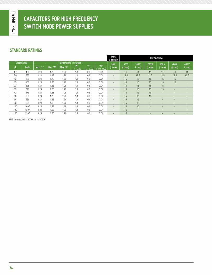
CapaCitors For HiGH FreQuenCy sWitCH Mode poWer supplies
Type
DpM
90
74
standard ratinGstYpe
Dpm 90 mtYpe Dpm 90
Capacitance Dimensions (in inches)50 V
(i. rms)50 V
(i. rms)100 V
(i. rms)200 V
(i. rms)250 V
(i. rms)400 V
(i. rms)630 V
(i. rms)μF Code max. "l" max. "e" max. "h""X"
+ / - 0.02"Y"
+ / - 0.02"W"
+10% -0.024.7 475 1.24 1.28 1.26 1.1 0.6 0.04 - 11 11 11 11 11 115.6 565 1.24 1.28 1.26 1.1 0.6 0.04 - 12.5 12.5 12.5 12.5 12.5 12.512 126 1.24 1.28 1.26 1.1 0.6 0.04 - 15 15 15 15 15 -15 156 1.24 1.28 1.26 1.1 0.6 0.04 - 15 15 15 15 15 -33 336 1.24 1.28 1.26 1.1 0.6 0.04 - 15 15 15 15 - -39 396 1.24 1.28 1.26 1.1 0.6 0.04 - 15 15 15 15 - -47 476 1.24 1.28 1.26 1.1 0.6 0.04 - 15 15 15 - - -56 566 1.24 1.28 1.26 1.1 0.6 0.04 - 15 15 15 - - -68 686 1.24 1.28 1.26 1.1 0.6 0.04 - 15 15 - - - -82 826 1.24 1.28 1.26 1.1 0.6 0.04 - 15 15 - - - -100 1007 1.24 1.28 1.26 1.1 0.6 0.04 - 15 15 - - - -120 1207 1.24 1.28 1.26 1.1 0.6 0.04 - 15 - - - - -150 1507 1.24 1.28 1.26 1.1 0.6 0.04 - 15 - - - - -
RMS current rated at 300kHz up to 105°C.

75
CapaCitors For HiGH FreQuenCy sWitCH Mode poWer supplies
Type
DpM
907
diMensions (in inches)
pHysiCal CHaraCteristiCsConstRuCtion:Dielectric: Metalized polyethylene terephtalate. Self healing, low inductance.
Case: Thermoplastic case. Epoxy resin molded.
leaD mateRial: DPM 907 - Termination are radial leads.
maRking:Dearborn trademark, type or catalog number, capacitance, tolerance and voltage.
eleCtriCal speCiFiCationsopeRating tempeRatuRe Range:-55°C to +125°C
Dissipation FaCtoR:Maximum 1% @ 1kHz
insulation ResistanCe:≥ 7,500 MΩ for CR ≤ 0.33 μF≥ 2,500 MΩ.μF for CR > 0.33 μF
DieleCtRiC WithstanDing Voltage (DWV): 1.6 x rated voltage
insulation betWeen leaDs & Case: 50,000 MΩ
peRmissible CuRRent:@ 300kHz up to 105°C = I. rms
@ 300kHz at 125°C =0.1I. rms
aVailable CapaCitanCe toleRanCes:±20% & ± 10%
L
≥ 0.
79
X Y
H
E
W

CapaCitors For HiGH FreQuenCy sWitCH Mode poWer supplies
Type
DpM
907
76
standard ratinGstYpe Dpm 907
Capacitance Dimensions (in inches)63 V
(i. rms)100 V
(i. rms)160 V
(i. rms)250 V
(i. rms)400 V
(i. rms)500 V
(i. rms)630 V
(i. rms)800 V
(i. rms)1,000 V (i. rms)
1,250 V (i. rms)μF Code max. "l" max. "e" max. "h"
"X" +/- 0.02
"Y" +/- 0.02
"W" gauge
0.22 224 0.807 0.807 0.256 0.701 0.4 18 0.8 0.8 0.8 0.8 0.8 0.8 0.8 0.9 - -0.27 274 0.807 0.807 0.256 0.701 0.4 18 0.9 0.9 0.9 0.9 0.9 0.9 0.9 - - -0.33 334 0.807 0.807 0.256 0.701 0.4 18 1.1 1.1 1.1 1.1 1.1 1.1 1.1 - - -0.39 394 0.807 0.807 0.256 0.701 0.4 18 1.1 1.1 1.1 1.1 1.1 1.1 1.3 - - -0.47 474 0.807 0.807 0.256 0.701 0.4 18 1.3 1.3 1.3 1.3 1.3 1.3 - - - -0.56 564 0.807 0.807 0.256 0.701 0.4 18 1.5 1.5 1.5 1.5 1.5 1.5 - - - -0.68 684 0.807 0.807 0.256 0.701 0.4 18 1.9 1.9 1.9 1.9 1.9 1.9 - - - -0.82 824 0.807 0.807 0.256 0.701 0.4 18 2.5 2.5 2.5 2.5 2.5 - - - - -
1 105 0.807 0.807 0.256 0.701 0.4 18 3.1 3.1 3.1 3.1 3.1 - - - - -1.5 155 0.807 0.807 0.256 0.701 0.4 18 1.5 1.5 1.5 1.5 - - - - - -2.2 225 0.807 0.807 0.256 0.701 0.4 18 2.2 2.2 2.2 2.2 - - - - - -2.7 275 0.807 0.807 0.256 0.701 0.4 18 2.4 2.4 2.4 2.4 - - - - - -3.3 335 0.807 0.807 0.256 0.701 0.4 18 2 2 2 - - - - - - -3.9 395 0.807 0.807 0.256 0.701 0.4 18 2.5 2.5 2.5 - - - - - - -4.7 475 0.807 0.807 0.256 0.701 0.4 18 2.5 2.5 3.1 - - - - - - -5.6 565 0.807 0.807 0.256 0.701 0.4 18 3.2 3.2 3.2 - - - - - - -6.8 685 0.807 0.807 0.256 0.701 0.4 18 4.3 4.3 4.3 - - - - - - -8.2 825 0.807 0.807 0.256 0.701 0.4 18 3.2 3.2 5.2 - - - - - - -10 106 0.807 0.807 0.256 0.701 0.4 18 4 - - - - - - - - -12 126 0.807 0.807 0.256 0.701 0.4 18 5 - - - - - - - - -
0.082 823 0.807 0.807 0.315 0.701 0.4 18 0.5 0.5 0.5 0.5 0.5 0.5 0.5 0.5 0.5 0.50.1 104 0.807 0.807 0.315 0.701 0.4 18 0.7 0.7 0.7 0.7 0.7 0.7 0.7 0.7 0.7 0.7
0.15 154 0.807 0.807 0.315 0.701 0.4 18 0.8 0.8 0.8 0.8 0.8 0.8 0.8 0.8 0.8 -0.22 224 0.807 0.807 0.315 0.701 0.4 18 1.1 1.1 1.1 1.1 1.1 1.1 1.1 1.1 1.1 -0.27 274 0.807 0.807 0.315 0.701 0.4 18 1.1 1.1 1.1 1.1 1.1 1.1 1.1 1.1 - -0.33 334 0.807 0.807 0.315 0.701 0.4 18 1.4 1.4 1.4 1.4 1.4 1.4 1.4 1.4 - -0.47 474 0.807 0.807 0.315 0.701 0.4 18 1.6 1.6 1.6 1.6 1.6 1.6 1.6 - - -0.56 564 0.807 0.807 0.315 0.701 0.4 18 2 2 2 2 2 2 2 - - -0.82 824 0.807 0.807 0.315 0.701 0.4 18 2.3 2.3 2.3 2.3 2.3 2.3 - - - -
1 105 0.807 0.807 0.315 0.701 0.4 18 2.8 2.8 2.8 2.8 2.8 2.8 - - - -1.2 125 0.807 0.807 0.315 0.701 0.4 18 3.2 3.2 3.2 3.2 3.2 - - - - -1.5 155 0.807 0.807 0.315 0.701 0.4 18 4 4 4 4 4 - - - - -3.3 335 0.807 0.807 0.315 0.701 0.4 18 2.6 2.6 2.6 2.6 - - - - - -5.6 565 0.807 0.807 0.315 0.701 0.4 18 4 4 4 - - - - - - -6.8 685 0.807 0.807 0.315 0.701 0.4 18 5 5 5 - - - - - - -10 106 0.807 0.807 0.315 0.701 0.4 18 6.4 6.4 - - - - - - - -15 156 0.807 0.807 0.315 0.701 0.4 18 6.3 - - - - - - - - -
RMS current rated at 300kHz up to 105°C.

CapaCitors For HiGH FreQuenCy sWitCH Mode poWer supplies
Type
DpM
907
77
standard ratinGstYpe Dpm 907
Capacitance Dimensions (in inches)63 V
(i. rms)100 V
(i. rms)160 V
(i. rms)250 V
(i. rms)400 V
(i. rms)500 V
(i. rms)630 V
(i. rms)800 V
(i. rms)1,000 V (i. rms)
1,250 V (i. rms)μF Code max. "l" max. "e" max. "h"
"X" +/- 0.02
"Y" +/- 0.02
"W" gauge
0.12 124 0.807 0.807 0.492 0.701 0.4 18 0.8 0.8 0.8 0.8 0.8 0.8 0.8 0.8 0.8 0.80.15 154 0.807 0.807 0.492 0.701 0.4 18 1 1 1 1 1 1 1 1 1 10.18 184 0.807 0.807 0.492 0.701 0.4 18 1.2 1.2 1.2 1.2 1.2 1.2 1.2 1.2 1.2 1.20.22 224 0.807 0.807 0.492 0.701 0.4 18 1.5 1.5 1.5 1.5 1.5 1.5 1.5 1.5 1.5 1.50.27 274 0.807 0.807 0.492 0.701 0.4 18 1.4 1.4 1.4 1.4 1.4 1.4 1.4 1.4 1.4 -0.33 334 0.807 0.807 0.492 0.701 0.4 18 1.7 1.7 1.7 1.7 1.7 1.7 1.7 1.7 1.7 -0.39 394 0.807 0.807 0.492 0.701 0.4 18 1.6 1.6 1.6 1.6 1.6 1.6 1.6 1.6 2 -0.47 474 0.807 0.807 0.492 0.701 0.4 18 1.9 1.9 1.9 1.9 1.9 1.9 1.9 1.9 - -0.56 564 0.807 0.807 0.492 0.701 0.4 18 2.3 2.3 2.3 2.3 2.3 2.3 2.3 2.3 - -0.68 684 0.807 0.807 0.492 0.701 0.4 18 2.5 2.5 2.5 2.5 2.5 2.5 2.5 2.8 - -0.82 824 0.807 0.807 0.492 0.701 0.4 18 3 3 3 3 3 3 3 - - -
1 105 0.807 0.807 0.492 0.701 0.4 18 3.2 3.2 3.2 3.2 3.2 3.2 3.2 - - -1.2 125 0.807 0.807 0.492 0.701 0.4 18 3.3 3.3 3.3 3.3 3.3 3.3 - - - -1.5 155 0.807 0.807 0.492 0.701 0.4 18 4.2 4.2 4.2 4.2 4.2 4.2 - - - -1.8 185 0.807 0.807 0.492 0.701 0.4 18 4 4 4 4 4 - - - - -2.2 225 0.807 0.807 0.492 0.701 0.4 18 4.5 4.5 4.5 4.5 4.5 - - - - -2.7 275 0.807 0.807 0.492 0.701 0.4 18 5 5 5 5 5 - - - - -3.9 395 0.807 0.807 0.492 0.701 0.4 18 3.1 3.1 3.1 3.1 - - - - - -4.7 475 0.807 0.807 0.492 0.701 0.4 18 3.7 3.7 3.7 3.7 - - - - - -5.6 565 0.807 0.807 0.492 0.701 0.4 18 4.4 4.4 4.4 4.4 - - - - - -8.2 825 0.807 0.807 0.492 0.701 0.4 18 6 6 6 - - - - - - -10 106 0.807 0.807 0.492 0.701 0.4 18 7.3 7.3 7.3 - - - - - - -12 126 0.807 0.807 0.492 0.701 0.4 18 6.4 6.4 - - - - - - - -15 156 0.807 0.807 0.492 0.701 0.4 18 8 8 - - - - - - - -18 186 0.807 0.807 0.492 0.701 0.4 18 7.6 8 - - - - - - - -22 226 0.807 0.807 0.492 0.701 0.4 18 8 8 - - - - - - - -
0.27 274 0.807 0.807 0.788 0.701 0.4 18 1.8 1.8 1.8 1.8 1.8 1.8 1.8 1.8 1.8 1.80.33 334 0.807 0.807 0.788 0.701 0.4 18 2.2 2.2 2.2 2.2 2.2 2.2 2.2 2.2 2.2 2.20.39 394 0.807 0.807 0.788 0.701 0.4 18 2.6 2.6 2.6 2.6 2.6 2.6 2.6 2.6 2.6 2.60.47 474 0.807 0.807 0.788 0.701 0.4 18 2.5 2.5 2.5 2.5 2.5 2.5 2.5 2.5 2.5 -0.56 564 0.807 0.807 0.788 0.701 0.4 18 2.9 2.9 2.9 2.9 2.9 2.9 2.9 2.9 2.9 -0.68 684 0.807 0.807 0.788 0.701 0.4 18 3.4 3.4 3.4 3.4 3.4 3.4 3.4 3.4 3.4 -0.82 824 0.807 0.807 0.788 0.701 0.4 18 3.4 3.4 3.4 3.4 3.4 3.4 3.4 3.4 - -
1 105 0.807 0.807 0.788 0.701 0.4 18 4.1 4.1 4.1 4.1 4.1 4.1 4.1 4.1 - -1.2 125 0.807 0.807 0.788 0.701 0.4 18 3.9 3.9 3.9 3.9 3.9 3.9 3.9 - -1.5 155 0.807 0.807 0.788 0.701 0.4 18 5 5 5 5 5 5 5 - - -1.8 185 0.807 0.807 0.788 0.701 0.4 18 5 5 5 5 5 5 5.8 - - -2.2 225 0.807 0.807 0.788 0.701 0.4 18 6.3 6.3 6.3 6.3 6.3 6.3 - - - -2.7 275 0.807 0.807 0.788 0.701 0.4 18 6.3 6.3 6.3 6.3 6.3 6.3 - - - -3.3 335 0.807 0.807 0.788 0.701 0.4 18 5 5 5 5 5 - - - - -3.9 395 0.807 0.807 0.788 0.701 0.4 18 5.9 5.9 5.9 5.9 5.9 - - - - -4.7 475 0.807 0.807 0.788 0.701 0.4 18 7.1 7.1 7.1 7.1 7.1 - - - - -6.8 685 0.807 0.807 0.788 0.701 0.4 18 5.4 5.4 5.4 5.4 - - - - - -8.2 825 0.807 0.807 0.788 0.701 0.4 18 6.5 6.5 6.5 6.5 - - - - - -10 106 0.807 0.807 0.788 0.701 0.4 18 7.9 7.9 7.9 7.9 - - - - - -12 126 0.807 0.807 0.788 0.701 0.4 18 8 8 8 - - - - - - -15 156 0.807 0.807 0.788 0.701 0.4 18 10 10 10 - - - - - - -18 186 0.807 0.807 0.788 0.701 0.4 18 10 10 10 - - - - - - -27 276 0.807 0.807 0.788 0.701 0.4 18 10 10 - - - - - - - -33 336 0.807 0.807 0.788 0.701 0.4 18 10 10 - - - - - - - -39 396 0.807 0.807 0.788 0.701 0.4 18 11.8 - - - - - - - - -
RMS current rated at 300kHz up to 105°C.

CapaCitors For HiGH FreQuenCy sWitCH Mode poWer supplies
Type
DpM
907
78
standard ratinGstYpe Dpm 907
Capacitance Dimensions (in inches)63 V
(i. rms)100 V
(i. rms)160 V
(i. rms)250 V
(i. rms)400 V
(i. rms)500 V
(i. rms)630 V
(i. rms)800 V
(i. rms)1,000 V (i. rms)
1,250 V (i. rms)μF Code max. "l" max. "e" max. "h"
"X" +/- 0.02
"Y" +/- 0.02
"W" gauge
0.47 474 0.807 0.807 1.181 0.701 0.4 18 3.1 3.1 3.1 3.1 3.1 3.1 3.1 3.1 3.1 3.10.56 564 0.807 0.807 1.181 0.701 0.4 18 3.7 3.7 3.7 3.7 3.7 3.7 3.7 3.7 3.7 3.70.82 824 0.807 0.807 1.181 0.701 0.4 18 4.3 4.3 4.3 4.3 4.3 4.3 4.3 4.3 4.3 -
1 105 0.807 0.807 1.181 0.701 0.4 18 5.2 5.2 5.2 5.2 5.2 5.2 5.2 5.2 5.2 -1.2 125 0.807 0.807 1.181 0.701 0.4 18 5 5 5 5 5 5 5 5 - -1.5 155 0.807 0.807 1.181 0.701 0.4 18 6.2 6.2 6.2 6.2 6.2 6.2 6.2 6.2 - -2.2 225 0.807 0.807 1.181 0.701 0.4 18 7.2 7.2 7.2 7.2 7.2 7.2 7.2 - - -2.7 275 0.807 0.807 1.181 0.701 0.4 18 8.8 8.8 8.8 8.8 8.8 8.8 8.8 - - -3.3 335 0.807 0.807 1.181 0.701 0.4 18 6.3 6.3 3.6 6.3 6.3 6.3 10.8 - - -3.9 395 0.807 0.807 1.181 0.701 0.4 18 8 8 8 8 8 8 - - - -4.7 475 0.807 0.807 1.181 0.701 0.4 18 8 8 8 8 8 8 - - - -5.6 565 0.807 0.807 1.181 0.701 0.4 18 7.9 7.9 7.9 7.9 7.9 - - - - -6.8 685 0.807 0.807 1.181 0.701 0.4 18 9.6 9.6 9.6 9.6 9.6 - - - - -8.2 825 0.807 0.807 1.181 0.701 0.4 18 11.5 11.5 11.5 11.5 11.5 - - - - -12 126 0.807 0.807 1.181 0.701 0.4 18 9.5 9.5 9.5 9.5 - - - - - -15 156 0.807 0.807 1.181 0.701 0.4 18 11.9 11.9 11.9 11.9 - - - - - -18 186 0.807 0.807 1.181 0.701 0.4 18 12.5 12.5 12.5 12.5 - - - - - -22 226 0.807 0.807 1.181 0.701 0.4 18 10 10 10 - - - - - - -27 276 0.807 0.807 1.181 0.701 0.4 18 12.5 12.5 12.5 - - - - - - -33 336 0.807 0.807 1.181 0.701 0.4 18 12.5 12.5 12.5 - - - - - - -39 396 0.807 0.807 1.181 0.701 0.4 18 12.5 12.5 - - - - - - - -47 476 0.807 0.807 1.181 0.701 0.4 18 12.5 12.5 - - - - - - - -56 566 0.807 0.807 1.181 0.701 0.4 18 12.5 - - - - - - - - -
0.68 684 1.24 1.28 0.866 1.1 0.6 18 2.4 2.4 2.4 2.4 2.4 2.4 2.4 2.4 2.4 2.41 105 1.24 1.28 0.866 1.1 0.6 18 3.6 3.6 3.6 3.6 3.6 3.6 3.6 3.6 3.6 3.6
1.2 125 1.24 1.28 0.866 1.1 0.6 18 3.4 3.4 3.4 3.4 3.4 3.4 3.4 3.4 3.4 4.31.5 155 1.24 1.28 0.866 1.1 0.6 18 4.3 4.3 4.3 4.3 4.3 4.3 4.3 4.3 4.3 5.41.8 185 1.24 1.28 0.866 1.1 0.6 18 4.3 4.3 4.3 4.3 4.3 4.3 4.3 4.3 5.1 -2.2 225 1.24 1.28 0.866 1.1 0.6 18 5.2 5.2 5.2 5.2 5.2 5.2 5.2 5.2 6.2 -2.7 275 1.24 1.28 0.866 1.1 0.6 18 6.4 6.4 6.4 6.4 6.4 6.4 6.4 6.4 - -3.3 335 1.24 1.28 0.866 1.1 0.6 18 7.8 7.8 7.8 7.8 7.8 7.8 7.8 7.8 - -3.9 395 1.24 1.28 0.866 1.1 0.6 18 7 7 7 7 7 7 7 - - -4.7 475 1.24 1.28 0.866 1.1 0.6 18 8.5 8.5 8.5 8.5 8.5 8.5 8.5 - - -5.6 565 1.24 1.28 0.866 1.1 0.6 18 7.9 7.9 7.9 7.9 7.9 7.9 10.1 - - -6.8 685 1.24 1.28 0.866 1.1 0.6 18 9.6 9.6 9.6 9.6 9.6 9.6 - - - -8.2 825 1.24 1.28 0.866 1.1 0.6 18 11.5 11.5 11.5 11.5 11.5 11.5 - - - -10 106 1.24 1.28 0.866 1.1 0.6 18 11.2 11.2 11.2 11.2 11.2 14 - - - -12 126 1.24 1.28 0.866 1.1 0.6 18 13.4 13.4 13.4 13.4 13.4 - - - - -15 156 1.24 1.28 0.866 1.1 0.6 18 15 15 15 15 15 - - - - -22 226 1.24 1.28 0.866 1.1 0.6 18 9.9 9.9 9.9 9.9 - - - - - -27 276 1.24 1.28 0.866 1.1 0.6 18 12.1 12.1 12.1 12.1 - - - - - -33 336 1.24 1.28 0.866 1.1 0.6 18 14.9 14.9 14.9 14.9 - - - - - -39 396 1.24 1.28 0.866 1.1 0.6 18 15 15 15 - - - - - - -47 476 1.24 1.28 0.866 1.1 0.6 18 15 15 15 - - - - - - -56 566 1.24 1.28 0.866 1.1 0.6 18 15 15 15 - - - - - - -68 686 1.24 1.28 0.866 1.1 0.6 18 15 15 - - - - - - - -82 826 1.24 1.28 0.866 1.1 0.6 18 15 15 - - - - - - - -
100 107 1.24 1.28 0.866 1.1 0.6 18 15 15 - - - - - - - -120 127 1.24 1.28 0.866 1.1 0.6 18 15 - - - - - - - - -
RMS current rated at 300kHz up to 105°C.

CapaCitors For HiGH FreQuenCy sWitCH Mode poWer supplies
Type
DpM
907
79
standard ratinGstYpe Dpm 907
Capacitance Dimensions (in inches)63 V
(i. rms)100 V
(i. rms)160 V
(i. rms)250 V
(i. rms)400 V
(i. rms)500 V
(i. rms)630 V
(i. rms)800 V
(i. rms)1,000 V (i. rms)
1,250 V (i. rms)μF Code max. "l" max. "e" max. "h"
"X" +/- 0.02
"Y" +/- 0.02
"W" gauge
1.8 185 1.24 1.28 1.26 1.1 0.6 18 6.5 6.5 6.5 6.5 6.5 6.5 6.5 6.5 6.5 6.52.2 225 1.24 1.28 1.26 1.1 0.6 18 7.9 7.9 7.9 7.9 7.9 7.9 7.9 7.9 7.9 7.92.7 275 1.24 1.28 1.26 1.1 0.6 18 7.7 7.7 7.7 7.7 7.7 7.7 7.7 7.7 7.7 -3.3 335 1.24 1.28 1.26 1.1 0.6 18 9.4 9.4 9.4 9.4 9.4 9.4 9.4 9.4 9.4 -3.9 395 1.24 1.28 1.26 1.1 0.6 18 9.2 9.2 9.2 9.2 9.2 9.2 9.2 9.2 11 -4.7 475 1.24 1.28 1.26 1.1 0.6 18 11 11 11 11 11 11 11 11 - -5.6 565 1.24 1.28 1.26 1.1 0.6 18 12.5 12.5 12.5 12.5 12.5 12.5 12.5 12.5 - -6.8 685 1.24 1.28 1.26 1.1 0.6 18 12.3 12.3 12.3 12.3 12.3 12.3 12.3 - - -8.2 825 1.24 1.28 1.26 1.1 0.6 18 14.7 14.7 14.7 14.7 14.7 14.7 14.7 - - -10 106 1.24 1.28 1.26 1.1 0.6 18 15 15 15 15 15 15 15 - - -12 126 1.24 1.28 1.26 1.1 0.6 18 15 15 15 15 15 15 - - - -15 156 1.24 1.28 1.26 1.1 0.6 18 15 15 15 15 15 15 - - - -18 186 1.24 1.28 1.26 1.1 0.6 18 15 15 15 15 15 - - - - -22 226 1.24 1.28 1.26 1.1 0.6 18 15 15 15 15 15 - - - - -39 396 1.24 1.28 1.26 1.1 0.6 18 15 15 15 15 - - - - - -47 476 1.24 1.28 1.26 1.1 0.6 18 15 15 15 15 - - - - - -56 566 1.24 1.28 1.26 1.1 0.6 18 15 15 15 15 - - - - - -68 686 1.24 1.28 1.26 1.1 0.6 18 15 15 15 - - - - - - -82 826 1.24 1.28 1.26 1.1 0.6 18 15 15 15 - - - - - - -
100 107 1.24 1.28 1.26 1.1 0.6 18 15 15 15 - - - - - - -120 127 1.24 1.28 1.26 1.1 0.6 18 15 15 - - - - - - - -150 157 1.24 1.28 1.26 1.1 0.6 18 150 15 - - - - - - - -180 187 1.24 1.28 1.26 1.1 0.6 18 150 - - - - - - - - -
RMS current rated at 300kHz up to 105°C.

CapaCitors For HiGH FreQuenCy sWitCH Mode poWer supplies
Type
DpM
907
R1/R
2
80
pHysiCal CHaraCteristiCsConstRuCtion:Dielectric: Metalized polyethylene terephtalate. Self healing, low inductance.
Case: Thermoplastic case. Epoxy resin molded.
leaD mateRial: DPM 907 R1 & R2 - Termination are surface mount “SMD”.
maRking:Dearborn trademark, type or catalog number, capacitance, tolerance and voltage.
eleCtriCal speCiFiCationsopeRating tempeRatuRe Range:-55°C to +125°C
Dissipation FaCtoR: Maximum 1% @ 1kHz
insulation ResistanCe:≥ 7,500 MΩ for CR ≤ 0.33 μF≥ 2,500 MΩ.μF for CR >0.33 μF
DieleCtRiC WithstanDing Voltage (DWV): 1.6 x rated voltage
insulation betWeen leaDs & Case: 50,000 MΩ
peRmissible CuRRent:@ 300kHz up to 105°C = I. rms
@ 300kHz at 125°C =0.1 I. rms
aVailable CapaCitanCe toleRanCes:±20% & ± 10%
diMensions (in inches)
L0.12
E Ea
X
H H
0.012Max.
0.012Max.
± 0.01 L
e 1
0.12 ± 0.1
L0.12
E Ea
X
H H
0.012Max.
0.012Max.
± 0.01 L
e 1
0.12 ± 0.1
tYpe Dpm 907 R1
tYpe Dpm 907 R2

CapaCitors For HiGH FreQuenCy sWitCH Mode poWer supplies
Type
DpM
907
R1/R
2
81
standard ratinGstYpe Dpm 907 R1 / R2
Capacitance Dimensions (in inches)63 V
(i. rms)100 V
(i. rms)160 V
(i. rms)250 V
(i. rms)400 V
(i. rms)500 V
(i. rms)630 V
(i. rms)800 V
(i. rms)1,000 V (i. rms)
1,250 V (i. rms)μF Code max. "l" max. "e" max. "h"
"X" +/- 0.02
"e1" +/- 0.02
"a" +/- 0.002
0.22 224 0.807 0.807 0.256 0.394 0.591 0.1 0.8 0.8 0.8 0.8 0.8 0.8 0.8 0.9 - -0.27 274 0.807 0.807 0.256 0.394 0.591 0.1 0.9 0.9 0.9 0.9 0.9 0.9 0.9 - - -0.33 334 0.807 0.807 0.256 0.394 0.591 0.1 1.1 1.1 1.1 1.1 1.1 1.1 1.1 - - -0.39 394 0.807 0.807 0.256 0.394 0.591 0.1 1.1 1.1 1.1 1.1 1.1 1.1 1.3 - - -0.47 474 0.807 0.807 0.256 0.394 0.591 0.1 1.3 1.3 1.3 1.3 1.3 1.3 - - - -0.56 564 0.807 0.807 0.256 0.394 0.591 0.1 1.5 1.5 1.5 1.5 1.5 1.5 - - - -0.68 684 0.807 0.807 0.256 0.394 0.591 0.1 1.9 1.9 1.9 1.9 1.9 1.9 - - - -0.82 824 0.807 0.807 0.256 0.394 0.591 0.1 2.5 2.5 2.5 2.5 2.5 - - - - -
1 105 0.807 0.807 0.256 0.394 0.591 0.1 3.1 3.1 3.1 3.1 3.1 - - - - -1.5 155 0.807 0.807 0.256 0.394 0.591 0.1 1.5 1.5 1.5 1.5 - - - - - -2.2 225 0.807 0.807 0.256 0.394 0.591 0.1 2.2 2.2 2.2 2.2 - - - - - -2.7 275 0.807 0.807 0.256 0.394 0.591 0.1 2.4 2.4 2.4 2.4 - - - - - -3.3 335 0.807 0.807 0.256 0.394 0.591 0.1 2 2 2 - - - - - - -3.9 395 0.807 0.807 0.256 0.394 0.591 0.1 2.5 2.5 2.5 - - - - - - -4.7 475 0.807 0.807 0.256 0.394 0.591 0.1 2.5 2.5 3.1 - - - - - - -5.6 565 0.807 0.807 0.256 0.394 0.591 0.1 3.2 3.2 - - - - - - - -6.8 685 0.807 0.807 0.256 0.394 0.591 0.1 4.3 4.3 - - - - - - - -8.2 825 0.807 0.807 0.256 0.394 0.591 0.1 3.2 5.2 - - - - - - - -10 106 0.807 0.807 0.256 0.394 0.591 0.1 4 - - - - - - - - -12 126 0.807 0.807 0.256 0.394 0.591 0.1 5 - - - - - - - - -
0.082 823 0.807 0.807 0.315 0.394 0.591 0.1 0.5 0.5 0.5 0.5 0.5 0.5 0.5 0.5 0.5 0.50.1 104 0.807 0.807 0.315 0.394 0.591 0.1 0.7 0.7 0.7 0.7 0.7 0.7 0.7 0.7 0.7 0.7
0.15 154 0.807 0.807 0.315 0.394 0.591 0.1 0.8 0.8 0.8 0.8 0.8 0.8 0.8 0.8 0.8 -0.22 224 0.807 0.807 0.315 0.394 0.591 0.1 1.1 1.1 1.1 1.1 1.1 1.1 1.1 1.1 1.1 -0.27 274 0.807 0.807 0.315 0.394 0.591 0.1 1.1 1.1 1.1 1.1 1.1 1.1 1.1 1.1 - -0.33 334 0.807 0.807 0.315 0.394 0.591 0.1 1.4 1.4 1.4 1.4 1.4 1.4 1.4 1.4 - -0.47 474 0.807 0.807 0.315 0.394 0.591 0.1 1.6 1.6 1.6 1.6 1.6 1.6 1.6 - - -0.56 564 0.807 0.807 0.315 0.394 0.591 0.1 2 2 2 2 2 2 2 - - -0.82 824 0.807 0.807 0.315 0.394 0.591 0.1 2.3 2.3 2.3 2.3 2.3 2.3 - - - -
1 105 0.807 0.807 0.315 0.394 0.591 0.1 2.8 2.8 2.8 2.8 2.8 2.8 - - - -1.2 125 0.807 0.807 0.315 0.394 0.591 0.1 3.2 3.2 3.2 3.2 3.2 - - - - -1.5 155 0.807 0.807 0.315 0.394 0.591 0.1 4 4 4 4 4 - - - - -3.3 335 0.807 0.807 0.315 0.394 0.591 0.1 2.6 2.6 2.6 2.6 - - - - - -5.6 565 0.807 0.807 0.315 0.394 0.591 0.1 4 4 4 - - - - - - -6.8 685 0.807 0.807 0.315 0.394 0.591 0.1 5 5 5 - - - - - - -10 106 0.807 0.807 0.315 0.394 0.591 0.1 6.4 6.4 - - - - - - - -15 156 0.807 0.807 0.315 0.394 0.591 0.1 6.3 - - - - - - - - -
RMS current rated at 300kHz up to 105°C.

CapaCitors For HiGH FreQuenCy sWitCH Mode poWer supplies
Type
DpM
907
R1/R
2
82
standard ratinGstYpe Dpm 907 R1 / R2
Capacitance Dimensions (in inches)63 V
(i. rms)100 V
(i. rms)160 V
(i. rms)250 V
(i. rms)400 V
(i. rms)500 V
(i. rms)630 V
(i. rms)800 V
(i. rms)1,000 V (i. rms)
1,250 V (i. rms)μF Code max. "l" max. "e" max. "h"
"X" +/- 0.02
"e1" +/- 0.02
"a" +/- 0.002
0.12 124 0.807 0.807 0.492 0.394 0.591 0.1 0.8 0.8 0.8 0.8 0.8 0.8 0.8 0.8 0.8 0.80.15 154 0.807 0.807 0.492 0.394 0.591 0.1 1 1 1 1 1 1 1 1 1 10.18 184 0.807 0.807 0.492 0.394 0.591 0.1 1.2 1.2 1.2 1.2 1.2 1.2 1.2 1.2 1.2 1.20.22 224 0.807 0.807 0.492 0.394 0.591 0.1 1.5 1.5 1.5 1.5 1.5 1.5 1.5 1.5 1.5 1.50.27 274 0.807 0.807 0.492 0.394 0.591 0.1 1.4 1.4 1.4 1.4 1.4 1.4 1.4 1.4 1.4 -0.33 334 0.807 0.807 0.492 0.394 0.591 0.1 1.7 1.7 1.7 1.7 1.7 1.7 1.7 1.7 1.7 -0.39 394 0.807 0.807 0.492 0.394 0.591 0.1 1.6 1.6 1.6 1.6 1.6 1.6 1.6 1.6 2 -0.47 474 0.807 0.807 0.492 0.394 0.591 0.1 1.9 1.9 1.9 1.9 1.9 1.9 1.9 1.9 - -0.56 564 0.807 0.807 0.492 0.394 0.591 0.1 2.3 2.3 2.3 2.3 2.3 2.3 2.3 2.3 - -0.68 684 0.807 0.807 0.492 0.394 0.591 0.1 2.5 2.5 2.5 2.5 2.5 2.5 2.5 2.8 - -0.82 824 0.807 0.807 0.492 0.394 0.591 0.1 3 3 3 3 3 3 3 - - -
1 105 0.807 0.807 0.492 0.394 0.591 0.1 3.2 3.2 3.2 3.2 3.2 3.2 3.2 - - -1.2 125 0.807 0.807 0.492 0.394 0.591 0.1 3.3 3.3 3.3 3.3 3.3 3.3 - - - -1.5 155 0.807 0.807 0.492 0.394 0.591 0.1 4.2 4.2 4.2 4.2 4.2 4.2 - - - -1.8 185 0.807 0.807 0.492 0.394 0.591 0.1 4 4 4 4 4 - - - - -2.2 225 0.807 0.807 0.492 0.394 0.591 0.1 4.5 4.5 4.5 4.5 4.5 - - - - -2.7 275 0.807 0.807 0.492 0.394 0.591 0.1 5 5 5 5 5 - - - - -3.9 395 0.807 0.807 0.492 0.394 0.591 0.1 3.1 3.1 3.1 3.1 - - - - - -4.7 475 0.807 0.807 0.492 0.394 0.591 0.1 3.7 3.7 3.7 3.7 - - - - - -5.6 565 0.807 0.807 0.492 0.394 0.591 0.1 4.4 4.4 4.4 4.4 - - - - - -8.2 825 0.807 0.807 0.492 0.394 0.591 0.1 6 6 6 - - - - - - -10 106 0.807 0.807 0.492 0.394 0.591 0.1 7.3 7.3 7.3 - - - - - - -12 126 0.807 0.807 0.492 0.394 0.591 0.1 6.4 6.4 - - - - - - - -15 156 0.807 0.807 0.492 0.394 0.591 0.1 8 8 - - - - - - - -18 186 0.807 0.807 0.492 0.394 0.591 0.1 7.6 8 - - - - - - - -22 226 0.807 0.807 0.492 0.394 0.591 0.1 8 8 - - - - - - - -
0.27 274 0.807 0.807 0.788 0.394 0.591 0.1 1.8 1.8 1.8 1.8 1.8 1.8 1.8 1.8 1.8 1.80.33 334 0.807 0.807 0.788 0.394 0.591 0.1 2.2 2.2 2.2 2.2 2.2 2.2 2.2 2.2 2.2 2.20.39 394 0.807 0.807 0.788 0.394 0.591 0.1 2.6 2.6 2.6 2.6 2.6 2.6 2.6 2.6 2.6 2.60.47 474 0.807 0.807 0.788 0.394 0.591 0.1 2.5 2.5 2.5 2.5 2.5 2.5 2.5 2.5 2.5 -0.56 564 0.807 0.807 0.788 0.394 0.591 0.1 2.9 2.9 2.9 2.9 2.9 2.9 2.9 2.9 2.9 -0.68 684 0.807 0.807 0.788 0.394 0.591 0.1 3.4 3.4 3.4 3.4 3.4 3.4 3.4 3.4 3.4 -0.82 824 0.807 0.807 0.788 0.394 0.591 0.1 3.4 3.4 3.4 3.4 3.4 3.4 3.4 3.4 - -
1 105 0.807 0.807 0.788 0.394 0.591 0.1 4.1 4.1 4.1 4.1 4.1 4.1 4.1 4.1 - -1.2 125 0.807 0.807 0.788 0.394 0.591 0.1 3.9 3.9 3.9 3.9 3.9 3.9 3.9 - - -1.5 155 0.807 0.807 0.788 0.394 0.591 0.1 5 5 5 5 5 5 5 - - -1.8 185 0.807 0.807 0.788 0.394 0.591 0.1 5 5 5 5 5 5 5.8 - - -2.2 225 0.807 0.807 0.788 0.394 0.591 0.1 6.3 6.3 6.3 6.3 6.3 6.3 - - - -2.7 275 0.807 0.807 0.788 0.394 0.591 0.1 6.3 6.3 6.3 6.3 6.3 6.3 - - - -3.3 335 0.807 0.807 0.788 0.394 0.591 0.1 5 5 5 5 5 - - - - -3.9 395 0.807 0.807 0.788 0.394 0.591 0.1 5.9 5.9 5.9 5.9 5.9 - - - - -4.7 475 0.807 0.807 0.788 0.394 0.591 0.1 7.1 7.1 7.1 7.1 7.1 - - - - -6.8 685 0.807 0.807 0.788 0.394 0.591 0.1 5.4 5.4 5.4 5.4 - - - - - -8.2 825 0.807 0.807 0.788 0.394 0.591 0.1 6.5 6.5 6.5 6.5 - - - - - -10 106 0.807 0.807 0.788 0.394 0.591 0.1 7.9 7.9 7.9 7.9 - - - - - -12 126 0.807 0.807 0.788 0.394 0.591 0.1 8 8 8 - - - - - - -15 156 0.807 0.807 0.788 0.394 0.591 0.1 10 10 10 - - - - - - -18 186 0.807 0.807 0.788 0.394 0.591 0.1 10 10 10 - - - - - - -27 276 0.807 0.807 0.788 0.394 0.591 0.1 10 10 - - - - - - - -33 336 0.807 0.807 0.788 0.394 0.591 0.1 33 10 - - - - - - - -39 396 0.807 0.807 0.788 0.394 0.591 0.1 11.8 - - - - - - - - -
RMS current rated at 300kHz up to 105°C.

CapaCitors For HiGH FreQuenCy sWitCH Mode poWer supplies
Type
DpM
907
R1/R
2
83
standard ratinGstYpe Dpm 907 R1 / R2
Capacitance Dimensions (in inches)63 V
(i. rms)100 V
(i. rms)160 V
(i. rms)250 V
(i. rms)400 V
(i. rms)500 V
(i. rms)630 V
(i. rms)800 V
(i. rms)1,000 V (i. rms)
1,250 V (i. rms)μF Code max. "l" max. "e" max. "h"
"X" +/- 0.02
"e1" +/- 0.02
"a" +/- 0.002
0.47 474 0.807 0.807 1.181 0.394 0.591 0.1 3.1 3.1 3.1 3.1 3.1 3.1 3.1 3.1 3.1 3.10.56 564 0.807 0.807 1.181 0.394 0.591 0.1 3.7 3.7 3.7 3.7 3.7 3.7 3.7 3.7 3.7 3.70.82 824 0.807 0.807 1.181 0.394 0.591 0.1 4.3 4.3 4.3 4.3 4.3 4.3 4.3 4.3 4.3 -
1 105 0.807 0.807 1.181 0.394 0.591 0.1 5.2 5.2 5.2 5.2 5.2 5.2 5.2 5.2 5.2 -1.2 125 0.807 0.807 1.181 0.394 0.591 0.1 5 5 5 5 5 5 5 5 - -1.5 155 0.807 0.807 1.181 0.394 0.591 0.1 6.2 6.2 6.2 6.2 6.2 6.2 6.2 6.2 - -2.2 225 0.807 0.807 1.181 0.394 0.591 0.1 7.2 7.2 7.2 7.2 7.2 7.2 7.2 - - -2.7 275 0.807 0.807 1.181 0.394 0.591 0.1 8.8 8.8 8.8 8.8 8.8 8.8 8.8 - - -3.3 335 0.807 0.807 1.181 0.394 0.591 0.1 6.3 6.3 6.3 6.3 6.3 6.3 10.8 - - -3.9 395 0.807 0.807 1.181 0.394 0.591 0.1 8 8 8 8 8 8 - - - -4.7 455 0.807 0.807 1.181 0.394 0.591 0.1 8 8 8 8 8 8 - - - -5.6 565 0.807 0.807 1.181 0.394 0.591 0.1 7.9 7.9 7.9 7.9 7.9 - - - - -6.8 685 0.807 0.807 1.181 0.394 0.591 0.1 9.6 9.6 9.6 9.6 9.6 - - - - -8.2 825 0.807 0.807 1.181 0.394 0.591 0.1 11.5 11.5 11.5 11.5 11.5 - - - - -12 126 0.807 0.807 1.181 0.394 0.591 0.1 9.5 9.5 9.5 9.5 - - - - - -15 156 0.807 0.807 1.181 0.394 0.591 0.1 11.9 11.9 11.9 11.9 - - - - - -18 186 0.807 0.807 1.181 0.394 0.591 0.1 12.5 12.5 12.5 12.5 - - - - - -22 226 0.807 0.807 1.181 0.394 0.591 0.1 10 10 10 - - - - - - -27 276 0.807 0.807 1.181 0.394 0.591 0.1 12.5 12.5 12.5 - - - - - - -33 336 0.807 0.807 1.181 0.394 0.591 0.1 12.5 12.5 12.5 - - - - - - -39 396 0.807 0.807 1.181 0.394 0.591 0.1 12.5 12.5 - - - - - - - -47 476 0.807 0.807 1.181 0.394 0.591 0.1 12.5 12.5 - - - - - - - -56 566 0.807 0.807 1.181 0.394 0.591 0.1 12.5 - - - - - - - - -
0.68 684 1.24 1.28 0.866 0.945 0.945 0.158 2.4 2.4 2.4 2.4 2.4 2.4 2.4 2.4 2.4 2.41 105 1.24 1.28 0.866 0.945 0.945 0.158 3.6 3.6 3.6 3.6 3.6 3.6 3.6 3.6 3.6 3.6
1.2 12 1.24 1.28 0.866 0.945 0.945 0.158 3.4 3.4 3.4 3.4 3.4 3.4 3.4 3.4 3.4 4.31.5 155 1.24 1.28 0.866 0.945 0.945 0.158 4.3 4.3 4.3 4.3 4.3 4.3 4.3 4.3 4.3 5.41.8 185 1.24 1.28 0.866 0.945 0.945 0.158 4.3 4.3 4.3 4.3 4.3 4.3 4.3 4.3 5.1 -2.2 225 1.24 1.28 0.866 0.945 0.945 0.158 5.2 5.2 5.2 5.2 5.2 5.2 5.2 5.2 2.2 -2.7 275 1.24 1.28 0.866 0.945 0.945 0.158 6.4 6.4 6.4 6.4 6.4 6.4 6.4 6.4 - -3.3 335 1.24 1.28 0.866 0.945 0.945 0.158 7.8 7.8 7.8 7.8 7.8 7.8 7.8 7.8 - -3.9 395 1.24 1.28 0.866 0.945 0.945 0.158 7 7 7 7 7 7 7 - - -4.7 475 1.24 1.28 0.866 0.945 0.945 0.158 8.5 8.5 8.5 8.5 8.5 8.5 8.5 - - -5.6 565 1.24 1.28 0.866 0.945 0.945 0.158 7.9 7.9 7.9 7.9 7.9 7.9 10.1 - - -6.8 685 1.24 1.28 0.866 0.945 0.945 0.158 9.6 9.6 9.6 9.6 9.6 9.6 - - - -8.2 825 1.24 1.28 0.866 0.945 0.945 0.158 11.5 11.5 11.5 11.5 11.5 11.5 - - - -10 106 1.24 1.28 0.866 0.945 0.945 0.158 11.2 11.2 11.2 11.2 11.2 14 - - - -12 126 1.24 1.28 0.866 0.945 0.945 0.158 13.4 13.4 13.4 13.4 13.4 - - - - -15 156 1.24 1.28 0.866 0.945 0.945 0.158 15 15 15 15 15 - - - - -22 226 1.24 1.28 0.866 0.945 0.945 0.158 9.9 9.9 9.9 9.9 - - - - - -27 276 1.24 1.28 0.866 0.945 0.945 0.158 12.1 12.1 12.1 12.1 - - - - - -33 336 1.24 1.28 0.866 0.945 0.945 0.158 14.9 14.9 14.9 14.9 - - - - - -39 396 1.24 1.28 0.866 0.945 0.945 0.158 15 15 15 - - - - - - -47 476 1.24 1.28 0.866 0.945 0.945 0.158 15 15 15 - - - - - - -56 566 1.24 1.28 0.866 0.945 0.945 0.158 15 15 15 - - - - - - -68 686 1.24 1.28 0.866 0.945 0.945 0.158 15 15 - - - - - - - -82 826 1.24 1.28 0.866 0.945 0.945 0.158 15 15 - - - - - - - -
100 107 1.24 1.28 0.866 0.945 0.945 0.158 15 15 - - - - - - - -120 127 1.24 1.28 0.866 0.945 0.945 0.158 15 - - - - - - - - -
RMS current rated at 300kHz up to 105°C.

CapaCitors For HiGH FreQuenCy sWitCH Mode poWer supplies
Type
DpM
907
R1/R
2
84
standard ratinGstYpe Dpm 907 R1 / R2
Capacitance Dimensions (in inches)63 V
(i. rms)100 V
(i. rms)160 V
(i. rms)250 V
(i. rms)400 V
(i. rms)500 V
(i. rms)630 V
(i. rms)800 V
(i. rms)1,000 V (i. rms)
1,250 V (i. rms)μF Code max. "l" max. "e" max. "h"
"X" +/- 0.02
"e1" +/- 0.02
"a" +/- 0.002
1.8 185 1.24 1.28 1.26 0.945 0.945 0.158 6.5 6.5 6.5 6.5 6.5 6.5 6.5 6.5 6.5 6.52.2 225 1.24 1.28 1.26 0.945 0.945 0.158 7.9 7.9 7.9 7.9 7.9 7.9 7.9 7.9 7.9 7.92.7 275 1.24 1.28 1.26 0.945 0.945 0.158 7.7 7.7 7.7 7.7 7.7 7.7 7.7 7.7 7.7 -3.3 335 1.24 1.28 1.26 0.945 0.945 0.158 9.4 9.4 9.4 9.4 9.4 9.4 9.4 9.4 9.4 -3.9 395 1.24 1.28 1.26 0.945 0.945 0.158 7.7 7.7 7.7 7.7 7.7 7.7 7.7 7.7 11 -4.7 475 1.24 1.28 1.26 0.945 0.945 0.158 9.4 9.4 9.4 9.4 9.4 9.4 9.4 9.4 - -5.6 565 1.24 1.28 1.26 0.945 0.945 0.158 12.5 12.5 12.5 12.5 12.5 12.5 12.5 12.5 - -6.8 685 1.24 1.28 1.26 0.945 0.945 0.158 12.3 12.3 12.3 12.3 12.3 12.3 12.3 - - -8.2 825 1.24 1.28 1.26 0.945 0.945 0.158 14.7 14.7 14.7 14.7 14.7 14.7 14.7 - - -10 106 1.24 1.28 1.26 0.945 0.945 0.158 15 15 15 15 15 15 15 - - -12 126 1.24 1.28 1.26 0.945 0.945 0.158 15 15 15 15 15 15 - - - -15 156 1.24 1.28 1.26 0.945 0.945 0.158 15 15 15 15 15 15 - - - -18 186 1.24 1.28 1.26 0.945 0.945 0.158 15 15 15 15 15 - - - - -22 226 1.24 1.28 1.26 0.945 0.945 0.158 15 15 15 15 15 - - - - -39 396 1.24 1.28 1.26 0.945 0.945 0.158 15 15 15 15 - - - - - -47 476 1.24 1.28 1.26 0.945 0.945 0.158 15 15 15 15 - - - - - -56 566 1.24 1.28 1.26 0.945 0.945 0.158 15 15 15 15 - - - - - -68 686 1.24 1.28 1.26 0.945 0.945 0.158 15 15 15 - - - - - - -82 826 1.24 1.28 1.26 0.945 0.945 0.158 15 15 15 - - - - - - -
100 107 1.24 1.28 1.26 0.945 0.945 0.158 15 15 15 - - - - - - -120 127 1.24 1.28 1.26 0.945 0.945 0.158 15 15 - - - - - - - -150 157 1.24 1.28 1.26 0.945 0.945 0.158 15 15 - - - - - - - -180 187 1.24 1.28 1.26 0.945 0.945 0.158 15 - - - - - - - - -
RMS current rated at 300kHz up to 105°C.

CapaCitors For HiGH FreQuenCy sWitCH Mode poWer supplies
Type
DpM
907
N
85
diMensions (in inches)
pHysiCal CHaraCteristiCsConstRuCtion:Dielectric: Metalized polyethylene terephtalate. Self healing, low inductance.
Case: Thermoplastic case. Epoxy resin molded.
leaD mateRial: DPM 907 N - Termination are “DIL leads”.
maRking:Dearborn trademark, type or catalog number, capacitance, tolerance and voltage.
eleCtriCal speCiFiCationsopeRating tempeRatuRe Range:-55°C to +125°C
Dissipation FaCtoR:Maximum 1% @ 1kHz
insulation ResistanCe:≥ 7,500 MΩ for CR ≤ 0.33 μF≥ 2,500 MΩ.μF for CR >0.33 μF
DieleCtRiC WithstanDing Voltage (DWV): 1.6 x rated voltage
insulation betWeen leaDs & Case: 50,000 MΩ
peRmissible CuRRent:@ 300kHz up to 105°C = I. rms
@ 300kHz at 125°C =0.1 I. rms
aVailable CapaCitanCe toleRanCes:±20% & ± 10%
L
H
RS
0.08+ 0.02+ 0
E
L
H
E
X0.10
≥ 0.20
0.02
0.01

CapaCitors For HiGH FreQuenCy sWitCH Mode poWer supplies
Type
DpM
907
N
86
standard ratinGstYpe Dpm 907 n
Capacitance Dimensions (in inches)
63 V (i. rms)
100 V (i. rms)
160 V (i. rms)
250 V (i. rms)
400 V (i. rms)
500 V (i. rms)
630 V (i. rms)
800 V (i. rms)
1,000 V (i. rms)
1,250 V (i. rms)μF Code max. "l" max. "e" max. "h"
"X" + / - 0.02
nb con± 0.5% / +10% -0.05
0.22 224 0.807 0.807 0.256 0.701 0.28 x 0.08 0.8 0.8 0.8 0.8 0.8 0.8 0.8 0.9 - -0.27 274 0.807 0.807 0.256 0.701 0.28 x 0.08 0.9 0.9 0.9 0.9 0.9 0.9 0.9 - - -0.33 334 0.807 0.807 0.256 0.701 0.28 x 0.08 1.1 1.1 1.1 1.1 1.1 1.1 1.1 - - -0.39 394 0.807 0.807 0.256 0.701 0.28 x 0.08 1.1 1.1 1.1 1.1 1.1 1.1 1.3 - - -0.47 474 0.807 0.807 0.256 0.701 0.28 x 0.08 1.3 1.3 1.3 1.3 1.3 1.3 - - - -0.56 564 0.807 0.807 0.256 0.701 0.28 x 0.08 1.5 1.5 1.5 1.5 1.5 1.5 - - - -0.68 684 0.807 0.807 0.256 0.701 0.28 x 0.08 1.9 1.9 1.9 1.9 1.9 1.9 - - - -0.82 824 0.807 0.807 0.256 0.701 0.28 x 0.08 2.5 2.5 2.5 2.5 2.5 - - - - -
1 105 0.807 0.807 0.256 0.701 0.28 x 0.08 3.1 3.1 3.1 3.1 3.1 - - - - -1.5 155 0.807 0.807 0.256 0.701 0.28 x 0.08 1.5 1.5 1.5 1.5 - - - - - -2.2 225 0.807 0.807 0.256 0.701 0.28 x 0.08 2.2 2.2 2.2 2.2 - - - - - -2.7 275 0.807 0.807 0.256 0.701 0.28 x 0.08 2.4 2.4 2.4 2.4 - - - - - -3.3 335 0.807 0.807 0.256 0.701 0.28 x 0.08 2 2 2 - - - - - - -3.9 395 0.807 0.807 0.256 0.701 0.28 x 0.08 2.5 2.5 2.5 - - - - - - -4.7 475 0.807 0.807 0.256 0.701 0.28 x 0.08 2.5 2.5 3.1 - - - - - - -5.6 565 0.807 0.807 0.256 0.701 0.28 x 0.08 3.2 3.2 - - - - - - - -6.8 685 0.807 0.807 0.256 0.701 0.28 x 0.08 4.3 4.3 - - - - - - - -8.2 825 0.807 0.807 0.256 0.701 0.28 x 0.08 3.2 5.2 - - - - - - - -10 106 0.807 0.807 0.256 0.701 0.28 x 0.08 4 - - - - - - - - -12 126 0.807 0.807 0.256 0.701 0.28 x 0.08 5 - - - - - - - - -
0.082 823 0.807 0.807 0.315 0.701 0.28 x 0.08 0.5 0.5 0.5 0.5 0.5 0.5 0.5 0.5 0.5 0.50.1 104 0.807 0.807 0.315 0.701 0.28 x 0.08 0.7 0.7 0.7 0.7 0.7 0.7 0.7 0.7 0.7 0.70.15 154 0.807 0.807 0.315 0.701 0.28 x 0.08 0.8 0.8 0.8 0.8 0.8 0.8 0.8 0.8 0.8 -0.22 224 0.807 0.807 0.315 0.701 0.28 x 0.08 1.1 1.1 1.1 1.1 1.1 1.1 1.1 1.1 1.1 -0.27 274 0.807 0.807 0.315 0.701 0.28 x 0.08 1.1 1.1 1.1 1.1 1.1 1.1 1.1 1.1 - -0.33 334 0.807 0.807 0.315 0.701 0.28 x 0.08 1.4 1.4 1.4 1.4 1.4 1.4 1.4 1.4 - -0.47 474 0.807 0.807 0.315 0.701 0.28 x 0.08 1.6 1.6 1.6 1.6 1.6 1.6 1.6 - - -0.56 564 0.807 0.807 0.315 0.701 0.28 x 0.08 2 2 2 2 2 2 2 - - -0.82 824 0.807 0.807 0.315 0.701 0.28 x 0.08 2.3 2.3 2.3 2.3 2.3 2.3 - - - -
1 105 0.807 0.807 0.315 0.701 0.28 x 0.08 2.8 2.8 2.8 2.8 2.8 2.8 - - - -1.2 125 0.807 0.807 0.315 0.701 0.28 x 0.08 3.2 3.2 3.2 3.2 3.2 - - - - -
1.5 155 0.807 0.807 0.315 0.701 0.28 x 0.08 4 4 4 4 4 - - - - -
3.3 335 0.807 0.807 0.315 0.701 0.28 x 0.08 2.6 2.6 2.6 2.6 - - - - - -5.6 565 0.807 0.807 0.315 0.701 0.28 x 0.08 4 4 4 - - - - - - -6.8 685 0.807 0.807 0.315 0.701 0.28 x 0.08 5 5 5 - - - - - - -10 106 0.807 0.807 0.315 0.701 0.28 x 0.08 6.4 6.4 - - - - - - - -15 156 0.807 0.807 0.315 0.701 0.28 x 0.08 6.3 - - - - - - - - -
RMS current rated at 300kHz up to 105°C.

CapaCitors For HiGH FreQuenCy sWitCH Mode poWer supplies
Type
DpM
907
N
87
standard ratinGstYpe Dpm 907 n
Capacitance Dimensions (in inches)
63 V (i. rms)
100 V (i. rms)
160 V (i. rms)
250 V (i. rms)
400 V (i. rms)
500 V (i. rms)
630 V (i. rms)
800 V (i. rms)
1,000 V (i. rms)
1,250 V (i. rms)μF Code max. "l" max. "e" max. "h"
"X" + / - 0.02
nb con± 0.5% / +10% -0.05
0.12 124 0.807 0.807 0.492 0.701 0.28 x 0.08 0.8 0.8 0.8 0.8 0.8 0.8 0.8 0.8 0.8 0.80.15 154 0.807 0.807 0.492 0.701 0.28 x 0.08 1 1 1 1 1 1 1 1 1 10.18 184 0.807 0.807 0.492 0.701 0.28 x 0.08 1.2 1.2 1.2 1.2 1.2 1.2 1.2 1.2 1.2 1.20.22 224 0.807 0.807 0.492 0.701 0.28 x 0.08 1.5 1.5 1.5 1.5 1.5 1.5 1.5 1.5 1.5 1.50.27 274 0.807 0.807 0.492 0.701 0.28 x 0.08 1.4 1.4 1.4 1.4 1.4 1.4 1.4 1.4 1.4 -0.33 334 0.807 0.807 0.492 0.701 0.28 x 0.08 1.7 1.7 1.7 1.7 1.7 1.7 1.7 1.7 1.7 -0.39 394 0.807 0.807 0.492 0.701 0.28 x 0.08 1.6 1.6 1.6 1.6 1.6 1.6 1.6 1.6 2 -0.47 474 0.807 0.807 0.492 0.701 0.28 x 0.08 1.9 1.9 1.9 1.9 1.9 1.9 1.9 1.9 - -0.56 564 0.807 0.807 0.492 0.701 0.28 x 0.08 2.3 2.3 2.3 2.3 2.3 2.3 2.3 2.3 - -0.68 684 0.807 0.807 0.492 0.701 0.28 x 0.08 2.5 2.5 2.5 2.5 2.5 2.5 2.5 2.8 - -0.82 824 0.807 0.807 0.492 0.701 0.28 x 0.08 3 3 3 3 3 3 3 - - -
1 105 0.807 0.807 0.492 0.701 0.28 x 0.08 3.2 3.2 3.2 3.2 3.2 3.2 3.2 - - -1.2 125 0.807 0.807 0.492 0.701 0.28 x 0.08 3.3 3.3 3.3 3.3 3.3 3.3 - - - -1.5 155 0.807 0.807 0.492 0.701 0.28 x 0.08 4.7 4.7 4.7 4.7 4.7 4.7 - - - -1.8 185 0.807 0.807 0.492 0.701 0.28 x 0.08 4 4 4 4 4 - - - - -2.2 225 0.807 0.807 0.492 0.701 0.28 x 0.08 4.5 4.5 4.5 4.5 4.5 - - - - -2.7 275 0.807 0.807 0.492 0.701 0.28 x 0.08 5 5 5 5 5 - - - - -3.9 395 0.807 0.807 0.492 0.701 0.28 x 0.08 3.1 3.1 3.1 3.1 - - - - - -4.7 475 0.807 0.807 0.492 0.701 0.28 x 0.08 3.7 3.7 3.7 3.7 - - - - - -5.6 565 0.807 0.807 0.492 0.701 0.28 x 0.08 4.4 4.4 4.4 4.4 - - - - - -8.2 825 0.807 0.807 0.492 0.701 0.28 x 0.08 6 6 6 - - - - - - -10 106 0.807 0.807 0.492 0.701 0.28 x 0.08 7.3 7.3 7.3 - - - - - - -12 126 0.807 0.807 0.492 0.701 0.28 x 0.08 6.4 6.4 - - - - - - - -15 156 0.807 0.807 0.492 0.701 0.28 x 0.08 8 8 - - - - - - - -18 186 0.807 0.807 0.492 0.701 0.28 x 0.08 7.6 8 - - - - - - - -22 226 0.807 0.807 0.492 0.701 0.28 x 0.08 8 8 - - - - - - - -
0.27 274 0.807 0.807 0.788 0.701 0.28 x 0.08 1.8 1.8 1.8 1.8 1.8 1.8 1.8 1.8 1.8 1.80.33 334 0.807 0.807 0.788 0.701 0.28 x 0.08 2.2 2.2 2.2 2.2 2.2 2.2 2.2 2.2 2.2 2.20.39 394 0.807 0.807 0.788 0.701 0.28 x 0.08 2.6 2.6 2.6 2.6 2.6 2.6 2.6 2.6 2.6 2.60.47 474 0.807 0.807 0.788 0.701 0.28 x 0.08 2.5 2.5 2.5 2.5 2.5 2.5 2.5 2.5 2.5 -0.56 564 0.807 0.807 0.788 0.701 0.28 x 0.08 2.9 2.9 2.9 2.9 2.9 2.9 2.9 2.9 2.9 -0.68 684 0.807 0.807 0.788 0.701 0.28 x 0.08 3.4 3.4 3.4 3.4 3.4 3.4 3.4 3.4 3.4 -0.82 82 0.807 0.807 0.788 0.701 0.28 x 0.08 3.4 3.4 3.4 3.4 3.4 3.4 3.4 3.4 - -
1 105 0.807 0.807 0.788 0.701 0.28 x 0.08 4.1 4.1 4.1 4.1 4.1 4.1 4.1 4.1 - -1.2 125 0.807 0.807 0.788 0.701 0.28 x 0.08 3.9 3.9 3.9 3.9 3.9 3.9 3.9 - - -1.5 155 0.807 0.807 0.788 0.701 0.28 x 0.08 5 5 5 5 5 5 5 - - -1.8 185 0.807 0.807 0.788 0.701 0.28 x 0.08 5 5 5 5 5 5 5.8 - - -2.2 225 0.807 0.807 0.788 0.701 0.28 x 0.08 6.3 6.3 6.3 6.3 6.3 6.3 - - - -2.7 275 0.807 0.807 0.788 0.701 0.28 x 0.08 6.3 6.3 6.3 6.3 6.3 6.3 - - - -3.3 335 0.807 0.807 0.788 0.701 0.28 x 0.08 5 5 5 5 5 - - - - -3.9 395 0.807 0.807 0.788 0.701 0.28 x 0.08 5.9 5.9 5.9 5.9 5.9 - - - - -4.7 475 0.807 0.807 0.788 0.701 0.28 x 0.08 7.1 7.1 7.1 7.1 7.1 - - - - -6.8 685 0.807 0.807 0.788 0.701 0.28 x 0.08 5.4 5.4 5.4 5.4 - - - - - -8.2 825 0.807 0.807 0.788 0.701 0.28 x 0.08 6.5 6.5 6.5 6.5 - - - - - -10 106 0.807 0.807 0.788 0.701 0.28 x 0.08 7.9 7.9 7.9 7.9 - - - - - -12 126 0.807 0.807 0.788 0.701 0.28 x 0.08 8 8 8 - - - - - - -15 156 0.807 0.807 0.788 0.701 0.28 x 0.08 10 10 10 - - - - - - -18 186 0.807 0.807 0.788 0.701 0.28 x 0.08 10 10 10 - - - - - - -27 276 0.807 0.807 0.788 0.701 0.28 x 0.08 10 10 - - - - - - - -33 336 0.807 0.807 0.788 0.701 0.28 x 0.08 10 10 - - - - - - - -39 396 0.807 0.807 0.788 0.701 0.28 x 0.08 11.8 - - - - - - - - -
RMS current rated at 300kHz up to 105°C.

CapaCitors For HiGH FreQuenCy sWitCH Mode poWer supplies
Type
DpM
907
N
88
standard ratinGstYpe Dpm 907 n
Capacitance Dimensions (in inches)
63 V (i. rms)
100 V (i. rms)
160 V (i. rms)
250 V (i. rms)
400 V (i. rms)
500 V (i. rms)
630 V (i. rms)
800 V (i. rms)
1,000 V (i. rms)
1,250 V (i. rms)μF Code max. "l" max. "e" max. "h"
"X" + / - 0.02
nb con± 0.5% / +10% -0.05
0.47 474 0.807 0.807 1.181 0.701 0.28 x 0.08 3.1 3.1 3.1 3.1 3.1 3.1 3.1 3.1 3.1 3.10.56 564 0.807 0.807 1.181 0.701 0.28 x 0.08 3.7 3.7 3.7 3.7 3.7 3.7 3.7 3.7 3.7 3.70.82 824 0.807 0.807 1.181 0.701 0.28 x 0.08 4.3 4.3 4.3 4.3 4.3 4.3 4.3 4.3 4.3 -
1 105 0.807 0.807 1.181 0.701 0.28 x 0.08 5.2 5.2 5.2 5.2 5.2 5.2 5.2 5.2 5.2 -1.2 125 0.807 0.807 1.181 0.701 0.28 x 0.08 5 5 5 5 5 5 5 5 - -1.5 155 0.807 0.807 1.181 0.701 0.28 x 0.08 6.2 6.2 6.2 6.2 6.2 6.2 6.2 6.2 - -2.2 225 0.807 0.807 1.181 0.701 0.28 x 0.08 7.2 7.2 7.2 7.2 7.2 7.2 7.2 - - -2.7 275 0.807 0.807 1.181 0.701 0.28 x 0.08 8.8 8.8 8.8 8.8 8.8 8.8 8.8 - - -3.3 335 0.807 0.807 1.181 0.701 0.28 x 0.08 6.3 6.3 6.3 6.3 6.3 6.3 10.8 - - -3.9 395 0.807 0.807 1.181 0.701 0.28 x 0.08 8 8 8 8 8 8 - - - -4.7 475 0.807 0.807 1.181 0.701 0.28 x 0.08 8 8 8 8 8 8 - - - -5.6 565 0.807 0.807 1.181 0.701 0.28 x 0.08 7.9 7.9 7.9 7.9 7.9 - - - - -6.8 685 0.807 0.807 1.181 0.701 0.28 x 0.08 9.6 9.6 9.6 9.6 9.6 - - - - -8.2 825 0.807 0.807 1.181 0.701 0.28 x 0.08 11.5 11.5 11.5 11.5 11.5 - - - - -12 126 0.807 0.807 1.181 0.701 0.28 x 0.08 9.5 9.5 9.5 9.5 - - - - - -15 156 0.807 0.807 1.181 0.701 0.28 x 0.08 11.9 11.9 11.9 11.9 - - - - - -18 186 0.807 0.807 1.181 0.701 0.28 x 0.08 12.5 12.5 12.5 12.5 - - - - - -22 226 0.807 0.807 1.181 0.701 0.28 x 0.08 10 10 10 - - - - - - -27 276 0.807 0.807 1.181 0.701 0.28 x 0.08 12.5 12.5 12.5 - - - - - - -33 336 0.807 0.807 1.181 0.701 0.28 x 0.08 12.5 12.5 12.5 - - - - - - -39 396 0.807 0.807 1.181 0.701 0.28 x 0.08 12.5 12.5 - - - - - - - -47 476 0.807 0.807 1.181 0.701 0.28 x 0.08 12.5 12.5 - - - - - - - -56 566 0.807 0.807 1.181 0.701 0.28 x 0.08 12.5 - - - - - - - - -
0.68 684 1.24 1.28 0.866 1.1 0.43 x 0.08 2.4 2.4 2.4 2.4 2.4 2.4 2.4 2.4 2.4 2.41 105 1.24 1.28 0.866 1.1 0.43 x 0.08 3.6 3.6 3.6 3.6 3.6 3.6 3.6 3.6 3.6 3.6
1.2 12 1.24 1.28 0.866 1.1 0.43 x 0.08 3.4 3.4 3.4 3.4 3.4 3.4 3.4 3.4 3.4 4.31.5 155 1.24 1.28 0.866 1.1 0.43 x 0.08 4.3 4.3 4.3 4.3 4.3 4.3 4.3 4.3 4.3 5.41.8 185 1.24 1.28 0.866 1.1 0.43 x 0.08 4.3 4.3 4.3 4.3 4.3 4.3 4.3 4.3 5.1 -2.2 225 1.24 1.28 0.866 1.1 0.43 x 0.08 5.2 5.2 5.2 5.2 5.2 5.2 5.2 5.2 6.2 -2.7 275 1.24 1.28 0.866 1.1 0.43 x 0.08 6.4 6.4 6.4 6.4 6.4 6.4 6.4 6.4 - -3.3 335 1.24 1.28 0.866 1.1 0.43 x 0.08 7.8 7.8 7.8 7.8 7.8 7.8 7.8 7.8 - -3.9 395 1.24 1.28 0.866 1.1 0.43 x 0.08 7 7 7 7 7 7 7 - - -4.7 475 1.24 1.28 0.866 1.1 0.43 x 0.08 8.5 8.5 8.5 8.5 8.5 8.5 8.5 - - -5.6 565 1.24 1.28 0.866 1.1 0.43 x 0.08 7.9 7.9 7.9 7.9 7.9 7.9 10.1 - - -6.8 685 1.24 1.28 0.866 1.1 0.43 x 0.08 9.6 9.6 9.6 9.6 9.6 9.6 - - - -8.2 825 1.24 1.28 0.866 1.1 0.43 x 0.08 11.5 11.5 11.5 11.5 11.5 11.5 - - - -10 106 1.24 1.28 0.866 1.1 0.43 x 0.08 11.2 11.2 11.2 11.2 11.2 14 - - - -12 126 1.24 1.28 0.866 1.1 0.43 x 0.08 13.4 13.4 13.4 13.4 13.4 - - - - -15 156 1.24 1.28 0.866 1.1 0.43 x 0.08 15 15 15 15 15 - - - - -22 226 1.24 1.28 0.866 1.1 0.43 x 0.08 9.9 9.9 9.9 9.9 - - - - - -27 276 1.24 1.28 0.866 1.1 0.43 x 0.08 12.1 12.1 12.1 12.1 - - - - - -33 336 1.24 1.28 0.866 1.1 0.43 x 0.08 14.9 14.9 14.9 14.9 - - - - - -39 396 1.24 1.28 0.866 1.1 0.43 x 0.08 15 45 15 - - - - - - -47 476 1.24 1.28 0.866 1.1 0.43 x 0.08 15 15 15 - - - - - - -56 566 1.24 1.28 0.866 1.1 0.43 x 0.08 15 15 15 - - - - - - -68 686 1.24 1.28 0.866 1.1 0.43 x 0.08 15 15 - - - - - - - -82 826 1.24 1.28 0.866 1.1 0.43 x 0.08 15 15 - - - - - - - -100 107 1.24 1.28 0.866 1.1 0.43 x 0.08 15 15 - - - - - - - -120 127 1.24 1.28 0.866 1.1 0.43 x 0.08 15 - - - - - - - - -
RMS current rated at 300kHz up to 105°C.

CapaCitors For HiGH FreQuenCy sWitCH Mode poWer supplies
Type
DpM
907
N
89
standard ratinGstYpe Dpm 907 n
Capacitance Dimensions (in inches)
63 V (i. rms)
100 V (i. rms)
160 V (i. rms)
250 V (i. rms)
400 V (i. rms)
500 V (i. rms)
630 V (i. rms)
800 V (i. rms)
1,000 V (i. rms)
1,250 V (i. rms)μF Code max. "l" max. "e" max. "h"
"X" + / - 0.02
nb con± 0.5% / +10% -0.05
1.8 185 1.24 1.28 1.26 1.1 0.43 x 0.08 6.5 6.5 6.5 6.5 6.5 6.5 6.5 6.5 6.5 6.52.2 225 1.24 1.28 1.26 1.1 0.43 x 0.08 7.9 7.9 7.9 7.9 7.9 7.9 7.9 7.9 7.9 7.92.7 275 1.24 1.28 1.26 1.1 0.43 x 0.08 7.7 7.7 7.7 7.7 7.7 7.7 7.7 7.7 7.7 -3.3 335 1.24 1.28 1.26 1.1 0.43 x 0.08 9.4 9.4 9.4 9.4 9.4 9.4 9.4 9.4 9.4 -3.9 395 1.24 1.28 1.26 1.1 0.43 x 0.08 9.2 9.2 9.2 9.2 9.2 9.2 9.2 9.2 11 -4.7 475 1.24 1.28 1.26 1.1 0.43 x 0.08 11 11 11 11 11 11 11 11 - -5.6 565 1.24 1.28 1.26 1.1 0.43 x 0.08 12.5 12.5 12.5 12.5 12.5 12.5 12.5 12.5 - -6.8 685 1.24 1.28 1.26 1.1 0.43 x 0.08 12.3 12.3 12.3 12.3 12.3 12.3 12.3 - - -8.2 825 1.24 1.28 1.26 1.1 0.43 x 0.08 14.7 14.7 14.7 14.7 14.7 14.7 14.7 - - -10 106 1.24 1.28 1.26 1.1 0.43 x 0.08 15 15 15 15 15 15 15 - - -12 126 1.24 1.28 1.26 1.1 0.43 x 0.08 15 15 15 15 15 15 - - - -15 156 1.24 1.28 1.26 1.1 0.43 x 0.08 15 15 15 15 15 15 - - - -18 186 1.24 1.28 1.26 1.1 0.43 x 0.08 15 15 15 15 15 - - - - -22 226 1.24 1.28 1.26 1.1 0.43 x 0.08 15 15 15 15 15 - - - - -39 396 1.24 1.28 1.26 1.1 0.43 x 0.08 15 15 15 15 - - - - - -47 476 1.24 1.28 1.26 1.1 0.43 x 0.08 15 15 15 15 - - - - - -56 566 1.24 1.28 1.26 1.1 0.43 x 0.08 15 15 15 15 - - - - - -68 686 1.24 1.28 1.26 1.1 0.43 x 0.08 15 15 15 - - - - - - -82 826 1.24 1.28 1.26 1.1 0.43 x 0.08 15 15 15 - - - - - - -100 107 1.24 1.28 1.26 1.1 0.43 x 0.08 15 15 15 - - - - - - -120 127 1.24 1.28 1.26 1.1 0.43 x 0.08 15 15 - - - - - - - -150 157 1.24 1.28 1.26 1.1 0.43 x 0.08 15 15 - - - - - - - -180 187 1.24 1.28 1.26 1.1 0.43 x 0.08 15 - - - - - - - - -
RMS current rated at 300kHz up to 105°C.

90
Type
DpM
90
R1/R
2
diMensions (in inches)
pHysiCal CHaraCteristiCsConstRuCtion:Dielectric: Metalized Polyester (P.E.T.). Self healing, low inductance.
Case: Thermoplastic case. Epoxy resin molded.
leaD mateRial: DPM 90 R1 & R2 - Surface mount device.
maRking:Dearborn trademark, type or catalog number, capacitance, tolerance and voltage.
eleCtriCal speCiFiCationsopeRating tempeRatuRe Range: -55°C to +125°C
Dissipation FaCtoR: Maximum 1% @ 1kHz
insulation ResistanCe:≥ 3,750 MΩ for CR ≤ 0.33 and ≤ 100 VDC≥ 7,500 MΩ for CR ≤ 0.33 and > 100 VDC≥ 1,250 MΩ.μF for CR > 0.33 and ≤ 100 VDC≥ 2,500 MΩ.μF for CR > 0.33 and >100 VDC
DieleCtRiC WithstanDing Voltage (DWV): 1.6 x rated voltage
insulation betWeen leaDs & Case: 50,000 MΩ
peRmissible CuRRent:@ 300kHz up to 105°C = I. rms
@ 300kHz at 125°C = 0.1 I. rms
aVailable CapaCitanCe toleRanCes:±20% & ± 10%
L0.118
E Ea
X
H H
0.012Max.
0.012Max.
± 0.01 L
e 1
0.12 ± 0.1
L0.118
E Ea
X
H H
0.012Max.
0.012Max.
± 0.01 L
e 1
0.12 ± 0.1
Dpm 90 R1
Dpm 90 R2
CapaCitors For HiGH FreQuenCy sWitCH Mode poWer supplies

91
CapaCitors For HiGH FreQuenCy sWitCH Mode poWer supplies
Type
DpM
90
R1/R
2
standard ratinGstYpe
Dpm 90 m R1 / R2
tYpe Dpm 90 R1 / R2
Capacitance Dimensions (in inches)50 V
(i. rms)50 V
(i. rms)100 V
(i. rms)200 V
(i. rms)250 V
(i. rms)400 V
(i. rms)630 V
(i. rms)μF Code max. "l" max. "e" max. "h""e1"
± 0.02 "X"
± 0.02"a"
+10% -0.050.22 224 0.807 0.807 0.295 0.591 0.394 0.1 - 0.9 0.9 0.9 0.9 0.9 0.90.27 274 0.807 0.807 0.295 0.591 0.394 0.1 - 1.1 1.1 1.1 1.1 1.1 1.10.39 394 0.807 0.807 0.295 0.591 0.394 0.1 - 1.25 1.25 1.25 1.25 1.25 -0.47 474 0.807 0.807 0.295 0.591 0.394 0.1 - 1.6 1.6 1.6 1.6 1.6 -0.56 564 0.807 0.807 0.295 0.591 0.394 0.1 - 2 2 2 2 2 -0.68 684 0.807 0.807 0.295 0.591 0.394 0.1 - 2.5 2.5 2.5 2.5 2.5 -0.82 824 0.807 0.807 0.295 0.591 0.394 0.1 - 3.15 3.15 3.15 3.15 3.15 -
1 105 0.807 0.807 0.295 0.591 0.394 0.1 - 1.25 1.25 1.25 1.25 - -1.2 125 0.807 0.807 0.295 0.591 0.394 0.1 - 1.6 1.6 1.6 1.6 - -1.5 155 0.807 0.807 0.295 0.591 0.394 0.1 - 1.5 1.5 1.5 2 - -1.8 185 0.807 0.807 0.295 0.591 0.394 0.1 - 2.5 2.5 2.5 2.5 - -2.2 225 0.807 0.807 0.295 0.591 0.394 0.1 - 2.2 2.2 2.2 3.15 - -2.7 275 0.807 0.807 0.295 0.591 0.394 0.1 - 4 4 4 4 - -3.3 335 0.807 0.807 0.295 0.591 0.394 0.1 - 2 2 2.6 - - -3.9 395 0.807 0.807 0.295 0.591 0.394 0.1 - 2.5 2.5 - - - -4.7 475 0.807 0.807 0.295 0.591 0.394 0.1 - 3.15 3.15 - - - -5.6 565 0.807 0.807 0.295 0.591 0.394 0.1 - 4 4 - - - -6.8 685 0.807 0.807 0.295 0.591 0.394 0.1 - 5 5 - - - -8.2 825 0.807 0.807 0.295 0.591 0.394 0.1 - 4 - - - - -10 106 0.807 0.807 0.295 0.591 0.394 0.1 - 5 - - - - -12 126 0.807 0.807 0.295 0.591 0.394 0.1 - 6.3 - - - - -15 156 0.807 0.807 0.295 0.591 0.394 0.1 5.2 - - - - - -
0.33 334 0.807 0.807 0.355 0.591 0.394 0.1 - 1.4 1.4 1.4 1.4 1.4 1.40.39 394 0.807 0.807 0.355 0.591 0.394 0.1 - 1.6 1.6 1.6 1.6 1.6 1.6
1 105 0.807 0.807 0.355 0.591 0.394 0.1 - 4 4 4 4 4 -1.2 125 0.807 0.807 0.355 0.591 0.394 0.1 - 4 4 4 4 4 -3.3 335 0.807 0.807 0.355 0.591 0.394 0.1 - 5 5 5 5 - -3.9 395 0.807 0.807 0.355 0.591 0.394 0.1 - 3.1 3.1 3.1 5 - -4.7 475 0.807 0.807 0.355 0.591 0.394 0.1 - 3.7 3.7 3.7 - - -8.2 825 0.807 0.807 0.355 0.591 0.394 0.1 - 6.5 6.5 - - - -15 156 0.807 0.807 0.355 0.591 0.394 0.1 - 8 - - - - -18 186 0.807 0.807 0.355 0.591 0.394 0.1 6.2 - - - - - -22 226 0.807 0.807 0.355 0.591 0.394 0.1 7.6 - - - - - -
0.47 474 0.807 0.807 0.532 0.591 0.394 0.1 - 1.9 1.9 1.9 1.9 1.9 1.90.68 684 0.807 0.807 0.532 0.591 0.394 0.1 - 2.8 2.8 2.8 2.8 2.8 2.81.5 155 0.807 0.807 0.532 0.591 0.394 0.1 - 5 5 5 5 5 -1.8 185 0.807 0.807 0.532 0.591 0.394 0.1 - 5 5 5 5 5 -4.7 475 0.807 0.807 0.532 0.591 0.394 0.1 - 6.3 6.3 6.3 6.3 - -5.6 565 0.807 0.807 0.532 0.591 0.394 0.1 - 4.4 4.4 4.4 6.3 - -6.8 685 0.807 0.807 0.532 0.591 0.394 0.1 - 5.4 5.4 5.4 - - -10 106 0.807 0.807 0.532 0.591 0.394 0.1 - 8 8 - - - -12 126 0.807 0.807 0.532 0.591 0.394 0.1 - 8 8 - - - -18 186 0.807 0.807 0.532 0.591 0.394 0.1 - 10 - - - - -22 226 0.807 0.807 0.532 0.591 0.394 0.1 - 10 - - - - -27 276 0.807 0.807 0.532 0.591 0.394 0.1 9.4 - - - - - -33 336 0.807 0.807 0.532 0.591 0.394 0.1 11.5 - - - - - -
RMS current rated at 300kHz up to 105°C.

CapaCitors For HiGH FreQuenCy sWitCH Mode poWer supplies
Type
DpM
90
R1/R
2
92
standard ratinGstYpe
Dpm 90 m R1 / R2
tYpe Dpm 90 R1 / R2
Capacitance Dimensions (in inches)50 V
(i. rms)50 V
(i. rms)100 V
(i. rms)200 V
(i. rms)250 V
(i. rms)400 V
(i. rms)630 V
(i. rms)μF Code max. "l" max. "e" max. "h""e1"
± 0.02 "X"
± 0.02"a"
+10% -0.050.82 824 0.807 0.807 0.827 0.591 0.394 0.1 - 3.4 3.4 3.4 3.4 3.4 3.4
1 105 0.807 0.807 0.827 0.591 0.394 0.1 - 4.1 4.1 4.1 4.1 4.1 4.12.2 225 0.807 0.807 0.827 0.591 0.394 0.1 - 6.3 6.3 6.3 6.3 6.3 -2.7 275 0.807 0.807 0.827 0.591 0.394 0.1 - 6.3 6.3 6.3 6.3 6.3 -3.3 335 0.807 0.807 0.827 0.591 0.394 0.1 - 6.3 6.3 6.3 6.3 6.3 -6.8 685 0.807 0.807 0.827 0.591 0.394 0.1 - 8 8 8 8 - -8.2 825 0.807 0.807 0.827 0.591 0.394 0.1 - 6.5 6.5 6.5 8 - -10 106 0.807 0.807 0.827 0.591 0.394 0.1 - 7.9 7.9 7.9 8 - -12 126 0.807 0.807 0.827 0.591 0.394 0.1 - 9.5 9.5 9.5 - - -15 156 0.807 0.807 0.827 0.591 0.394 0.1 - 10 10 - - - -18 186 0.807 0.807 0.827 0.591 0.394 0.1 - 10 10 - - - -22 226 0.807 0.807 0.827 0.591 0.394 0.1 - 10 10 - - - -27 276 0.807 0.807 0.827 0.591 0.394 0.1 - 12.5 - - - - -33 336 0.807 0.807 0.827 0.591 0.394 0.1 - 12.5 - - - - -39 396 0.807 0.807 0.827 0.591 0.394 0.1 - 12.5 - - - - -47 476 0.807 0.807 0.827 0.591 0.394 0.1 12.5 - - - - - -56 566 0.807 0.807 0.827 0.591 0.394 0.1 12.5 - - - - - -68 686 0.807 0.807 0.827 0.591 0.394 0.1 12.5 - - - - - -
1.2 125 0.807 0.807 1.221 0.591 0.394 0.1 - 5 5 5 5 5 51.5 155 0.807 0.807 1.221 0.591 0.394 0.1 - 6.2 6.2 6.2 6.2 6.2 6.21.8 185 0.807 0.807 1.221 0.591 0.394 0.1 - 7.4 7.4 7.4 7.4 7.4 7.43.9 395 0.807 0.807 1.221 0.591 0.394 0.1 - 8 8 8 8 8 -4.7 475 0.807 0.807 1.221 0.591 0.394 0.1 - 8 8 8 8 8 -12 126 0.807 0.807 1.221 0.591 0.394 0.1 - 10 10 10 10 - -15 156 0.807 0.807 1.221 0.591 0.394 0.1 - 11.9 11.9 11.9 10 - -18 186 0.807 0.807 1.221 0.591 0.394 0.1 - 12.5 12.5 12.5 - - -27 276 0.807 0.807 1.221 0.591 0.394 0.1 - 12.5 12.5 - - - -33 336 0.807 0.807 1.221 0.591 0.394 0.1 - 12.5 12.5 - - - -47 476 0.807 0.807 1.221 0.591 0.394 0.1 - 12.5 - - - - -56 566 0.807 0.807 1.221 0.591 0.394 0.1 - 12.5 - - - - -82 826 0.807 0.807 1.221 0.591 0.394 0.1 12.5 - - - - - -100 107 0.807 0.807 1.221 0.591 0.394 0.1 12.5 - - - - - -
2.2 225 1.24 1.28 0.906 0.945 0.591 0.158 - 5.2 5.2 5.2 5.2 5.2 5.22.7 275 1.24 1.28 0.906 0.945 0.591 0.158 - 6.4 6.4 6.4 6.4 6.4 6.43.3 335 1.24 1.28 0.906 0.945 0.591 0.158 - 7.8 7.8 7.8 7.8 7.8 7.83.9 395 1.24 1.28 0.906 0.945 0.591 0.158 - 9.2 9.2 9.2 9.2 9.2 9.25.6 565 1.24 1.28 0.906 0.945 0.591 0.158 - 7.9 7.9 7.9 7.9 7.9 -6.8 685 1.24 1.28 0.906 0.945 0.591 0.158 - 9.6 9.6 9.6 9.6 9.6 -8.2 825 1.24 1.28 0.906 0.945 0.591 0.158 - 11.5 11.5 11.5 11.5 11.5 -10 106 1.24 1.28 0.906 0.945 0.591 0.158 - 14 14 14 14 14 -18 186 1.24 1.28 0.906 0.945 0.591 0.158 - 15 15 15 15 - -22 226 1.24 1.28 0.906 0.945 0.591 0.158 - 9.9 9.9 9.9 15 - -27 276 1.24 1.28 0.906 0.945 0.591 0.158 - 15 15 15 15 - -33 336 1.24 1.28 0.906 0.945 0.591 0.158 - 14.9 14.9 14.9 - - -39 396 1.24 1.28 0.906 0.945 0.591 0.158 - 15 15 - - - -47 476 1.24 1.28 0.906 0.945 0.591 0.158 - 15 15 - - - -56 566 1.24 1.28 0.906 0.945 0.591 0.158 - 15 15 - - - -68 686 1.24 1.28 0.906 0.945 0.591 0.158 - 15 - - - - -82 826 1.24 1.28 0.906 0.945 0.591 0.158 - 15 - - - - -100 107 1.24 1.28 0.906 0.945 0.591 0.158 - 15 - - - - -
RMS current rated at 300kHz up to 105°C.

CapaCitors For HiGH FreQuenCy sWitCH Mode poWer supplies
Type
DpM
90
R1/R
2
93
standard ratinGstYpe
Dpm 90 m R1 / R2
tYpe Dpm 90 R1 / R2
Capacitance Dimensions (in inches)50 V
(i. rms)50 V
(i. rms)100 V
(i. rms)200 V
(i. rms)250 V
(i. rms)400 V
(i. rms)630 V
(i. rms)μF Code max. "l" max. "e" max. "h""e1"
± 0.02 "X"
± 0.02"a"
+10% -0.054.7 475 1.24 1.28 1.3 0.945 0.591 0.158 - 11 11 11 11 11 115.6 565 1.24 1.28 1.3 0.945 0.591 0.158 - 12.5 12.5 12.5 12.5 12.5 12.512 126 1.24 1.28 1.3 0.945 0.591 0.158 - 15 15 15 15 15 -15 156 1.24 1.28 1.3 0.945 0.591 0.158 - 15 15 15 15 15 -33 336 1.24 1.28 1.3 0.945 0.591 0.158 - 15 15 15 15 - -39 396 1.24 1.28 1.3 0.945 0.591 0.158 - 15 15 15 15 - -47 476 1.24 1.28 1.3 0.945 0.591 0.158 - 15 15 15 - - -56 566 1.24 1.28 1.3 0.945 0.591 0.158 - 15 15 15 - - -68 686 1.24 1.28 1.3 0.945 0.591 0.158 - 15 15 - - - -82 826 1.24 1.28 1.3 0.945 0.591 0.158 - 15 15 - - - -100 107 1.24 1.28 1.3 0.945 0.591 0.158 - 15 15 - - - -120 127 1.24 1.28 1.3 0.945 0.591 0.158 - 15 - - - - -150 157 1.24 1.28 1.3 0.945 0.591 0.158 - 15 - - - - -
RMS current rated at 300kHz up to 105°C.
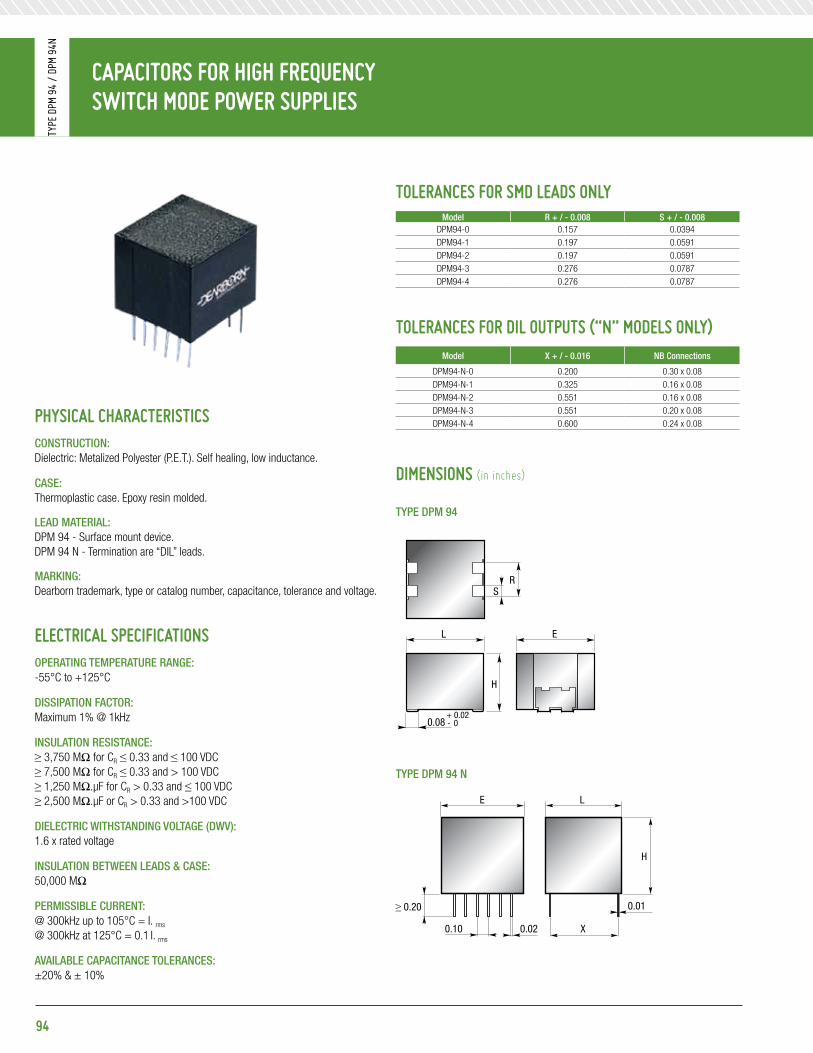
CapaCitors For HiGH FreQuenCy sWitCH Mode poWer supplies
Type
DpM
94
/ Dp
M 94
N
94
diMensions (in inches)
pHysiCal CHaraCteristiCsConstRuCtion:Dielectric: Metalized Polyester (P.E.T.). Self healing, low inductance.
Case: Thermoplastic case. Epoxy resin molded.
leaD mateRial: DPM 94 - Surface mount device. DPM 94 N - Termination are “DIL” leads.
maRking:Dearborn trademark, type or catalog number, capacitance, tolerance and voltage.
eleCtriCal speCiFiCationsopeRating tempeRatuRe Range: -55°C to +125°C
Dissipation FaCtoR: Maximum 1% @ 1kHz
insulation ResistanCe:≥ 3,750 MΩ for CR ≤ 0.33 and ≤ 100 VDC≥ 7,500 MΩ for CR ≤ 0.33 and > 100 VDC≥ 1,250 MΩ.μF for CR > 0.33 and ≤ 100 VDC≥ 2,500 MΩ.μF or CR > 0.33 and >100 VDC
DieleCtRiC WithstanDing Voltage (DWV): 1.6 x rated voltage
insulation betWeen leaDs & Case: 50,000 MΩ
peRmissible CuRRent:@ 300kHz up to 105°C = I. rms
@ 300kHz at 125°C = 0.1 I. rms
aVailable CapaCitanCe toleRanCes:±20% & ± 10%
L
H
RS
0.08+ 0.02 - 0
E
E
H
L
X0.10
≥ 0.20
0.02
0.01
L
H
RS
0.08+ 0.02 - 0
E
E
H
L
X0.10
≥ 0.20
0.02
0.01
tYpe Dpm 94
tYpe Dpm 94 n
toleranCes For sMd leads only model R + / - 0.008 s + / - 0.008
DPM94-0 0.157 0.0394DPM94-1 0.197 0.0591DPM94-2 0.197 0.0591DPM94-3 0.276 0.0787DPM94-4 0.276 0.0787
toleranCes For dil outputs (“n” Models only)model X + / - 0.016 nb Connections
DPM94-N-0 0.200 0.30 x 0.08DPM94-N-1 0.325 0.16 x 0.08DPM94-N-2 0.551 0.16 x 0.08DPM94-N-3 0.551 0.20 x 0.08DPM94-N-4 0.600 0.24 x 0.08

CapaCitors For HiGH FreQuenCy sWitCH Mode poWer supplies
Type
DpM
94
/ Dp
M 94
N
95
standard ratinGstYpe Dpm 94-0 / Dpm 94-n-0
Capacitance Dimensions (in inches) 50 V (i. rms)
63 V (i. rms)
100 V (i. rms)
200 V (i. rms)
250 V (i. rms)
400 V (i. rms)μF Code max. "l" max. "e" max. "h"
0.0082 822 0.315 0.295 0.177 0.1 0.1 0.1 0.1 0.1 0.10.01 103 0.315 0.295 0.177 0.1 0.1 0.1 0.1 0.1 0.10.012 123 0.315 0.295 0.177 0.2 0.2 0.2 0.2 0.2 0.20.015 153 0.315 0.295 0.177 0.2 0.2 0.2 0.2 0.2 0.20.018 183 0.315 0.295 0.177 0.3 0.3 0.3 0.3 0.3 0.30.027 273 0.315 0.295 0.177 0.1 0.1 0.1 0.1 0.1 -0.033 333 0.315 0.295 0.177 0.2 0.2 0.2 0.2 0.2 -0.039 393 0.315 0.295 0.177 0.2 0.2 0.2 0.2 0.2 -0.047 473 0.315 0.295 0.177 0.2 0.2 0.2 0.2 0.2 -0.056 563 0.315 0.295 0.177 0.2 0.2 0.2 0.2 0.3 -0.068 683 0.315 0.295 0.177 0.3 0.3 0.3 0.3 - -0.082 683 0.315 0.295 0.177 0.2 0.2 0.2 0.3 - -
0.1 104 0.315 0.295 0.177 0.3 0.3 0.3 0.3 - -0.12 124 0.315 0.295 0.177 0.4 0.4 0.4 - - -0.15 154 0.315 0.295 0.177 0.4 0.4 0.4 - - -0.18 184 0.315 0.295 0.177 0.4 0.4 0.4 - - -0.22 224 0.315 0.295 0.177 0.5 0.5 - - - -0.27 274 0.315 0.295 0.177 0.6 0.6 - - - -0.33 334 0.315 0.295 0.177 0.4 0.5 - - - -0.39 394 0.315 0.295 0.177 0.4 - - - - -0.47 474 0.315 0.295 0.177 0.5 - - - - -0.56 564 0.315 0.295 0.177 0.6 - - - - -0.68 684 0.315 0.295 0.177 0.8 - - - - -0.022 223 0.315 0.335 0.295 0.3 0.3 0.3 0.3 0.3 0.30.027 273 0.315 0.335 0.295 0.4 0.4 0.4 0.4 0.4 0.40.033 333 0.315 0.335 0.295 0.5 0.5 0.5 0.5 0.5 0.50.039 393 0.315 0.335 0.295 0.6 0.6 0.6 0.6 0.6 0.60.047 473 0.315 0.335 0.295 0.7 0.7 0.7 0.7 0.6 0.70.056 563 0.315 0.335 0.295 0.8 0.8 0.8 0.8 0.8 0.80.068 683 0.315 0.335 0.295 0.3 0.3 0.3 0.3 0.3 -0.082 823 0.315 0.335 0.295 0.4 0.4 0.4 0.3 0.4 -
0.1 104 0.315 0.335 0.295 0.5 0.5 0.5 0.5 0.5 -0.12 124 0.315 0.335 0.295 0.6 0.6 0.6 0.6 0.6 -0.15 154 0.315 0.335 0.295 0.7 0.7 0.7 0.7 0.7 -0.18 184 0.315 0.335 0.295 0.8 0.8 0.8 0.8 0.8 -0.22 224 0.315 0.335 0.295 0.7 0.7 0.7 0.7 - -0.27 274 0.315 0.335 0.295 0.8 0.8 0.8 0.8 - -0.33 334 0.315 0.335 0.295 0.9 0.9 0.9 - - -0.39 394 0.315 0.335 0.295 0.8 0.8 1 - - -0.47 574 0.315 0.335 0.295 1 1 1.1 - - -0.56 564 0.315 0.335 0.295 1.2 1.2 1.3 - - -0.68 684 0.315 0.335 0.295 1.4 1.4 - - - -0.82 824 0.315 0.335 0.295 0.9 1.1 - - - -
1 105 0.315 0.335 0.295 1.1 1.4 - - - -1.2 125 0.315 0.335 0.295 1.4 - - - - -1.5 155 0.315 0.335 0.295 1.7 - - - - -1.8 185 0.315 0.335 0.295 2 - - - - -
RMS current rated at 300kHz up to 105°C.

CapaCitors For HiGH FreQuenCy sWitCH Mode poWer supplies
Type
DpM
94
/ Dp
M 94
N
96
standard ratinGstYpe Dpm 94-1 / Dpm 94-n-1
Capacitance Dimensions (in inches) 50 V (i. rms)
63 V (i. rms)
100 V (i. rms)
200 V (i. rms)
250 V (i. rms)
400 V (i. rms)μF Code max. "l" max. "e" max. "h"
0.1 104 0.421 0.421 0.236 0.8 0.8 0.8 0.8 0.8 0.80.22 224 0.421 0.421 0.236 0.8 0.8 0.8 0.8 0.8 -0.27 274 0.421 0.421 0.236 1 1 1 1 1 -0.33* 334 0.421 0.421 0.236 0.6 0.6 0.6 0.6 1.2 -0.39 394 0.421 0.421 0.236 0.8 0.8 0.8 0.8 - -0.47 474 0.421 0.421 0.236 1 1 1 1 - -0.56 564 0.421 0.421 0.236 0.8 0.8 0.8 - - -0.68 684 0.421 0.421 0.236 1 1 1 - - -0.82 824 0.421 0.421 0.236 1.1 1.1 1.1 - - -
1 105 0.421 0.421 0.236 1.8 1.8 1.8 - - -1.5 155 0.421 0.421 0.236 1.7 1.7 - - - -1.8 185 0.421 0.421 0.236 2.1 2.1 - - - -2.2 225 0.421 0.421 0.236 1.3 - - - - -2.7 275 0.421 0.421 0.236 1.6 - - - - -3.3 335 0.421 0.421 0.236 1.9 - - - - -0.15 154 0.421 0.421 0.315 1.2 1.2 1.2 1.2 1.2 1.20.39 394 0.421 0.421 0.315 1.4 1.4 1.4 1.4 1.4 -0.47 474 0.421 0.421 0.315 1.7 1.7 1.7 1.7 1.7 -0.56 564 0.421 0.421 0.315 1.1 1.1 1.1 1.1 - -0.68 684 0.421 0.421 0.315 1.4 1.4 1.4 1.4 - -1.2 125 0.421 0.421 0.315 1.8 1.8 1.8 - - -1.5 155 0.421 0.421 0.315 2.2 2.2 2.2 - - -2.2 225 0.421 0.421 0.315 2.5 2.5 - - - -3.9 395 0.421 0.421 0.315 2.3 - - - - -4.7 475 0.421 0.421 0.315 2.8 - - - -0.22 224 0.421 0.421 0.394 1.7 1.7 1.7 1.7 1.7 1.70.56 564 0.421 0.421 0.394 2 2 2 2 2 -0.82 824 0.421 0.421 0.394 1.7 1.7 1.7 1.7 - -1.8 185 0.421 0.421 0.394 2.7 2.7 2.7 - - -2.7 275 0.421 0.421 0.394 3.1 3.1 - - - -3.3 335 0.421 0.421 0.394 3.8 3.8 - - - -5.6 565 0.421 0.421 0.394 3.3 - - - - -6.8 685 0.421 0.421 0.394 4.1 - - - - -0.68 684 0.421 0.421 0.473 2.4 2.4 2.4 2.4 2.4 -
1 105 0.421 0.421 0.473 2.1 2.1 2.1 2.1 - -2.2 225 0.421 0.421 0.473 2.1 2.1 3.5 - - -3.9 395 0.421 0.421 0.473 4.9 4.9 - - - -4.7 475 0.421 0.421 0.473 6 6 - - - -8.2 825 0.315 0.421 0.473 4.9 - - - - -10 1005 0.315 0.421 0.473 6 - - - - -
RMS current rated at 300kHz up to 105°C.

CapaCitors For HiGH FreQuenCy sWitCH Mode poWer supplies
Type
DpM
94
/ Dp
M 94
N
97
standard ratinGstYpe Dpm 94-2 / Dpm 94-n-2
Capacitance Dimensions (in inches) 50 V (i. rms)
63 V (i. rms)
100 V (i. rms)
200 V (i. rms)
250 V (i. rms)
400 V (i. rms)μF Code max. "l" max. "e" max. "h"
0.22 224 0.61 0.453 0.236 0.8 0.8 0.8 0.8 0.8 0.80.27 274 0.61 0.453 0.236 1 1 1 1 1 10.47 474 0.61 0.453 0.236 0.8 0.8 0.8 0.8 0.8 -0.56 564 0.61 0.453 0.236 0.9 0.9 0.9 0.9 0.9 -0.68 684 0.61 0.453 0.236 1.1 1.1 1.1 1.1 1.1 -0.82 824 0.61 0.453 0.236 0.8 0.8 0.8 0.8 - -
1 105 0.61 0.453 0.236 1 1 1 1 - -1.5 155 0.61 0.453 0.236 1.1 1.1 1.1 - - -1.8 185 0.61 0.453 0.236 1.4 1.4 1.4 - - -2.2 225 0.61 0.453 0.236 1.7 1.7 1.7 - - -3.3 335 0.61 0.453 0.236 1.9 1.9 - - - -3.9 395 0.61 0.453 0.236 2.3 2.3 - - - -4.7 475 0.61 0.453 0.236 1.4 - - - - -5.6 565 0.61 0.453 0.236 1.7 - - - - -6.8 685 0.61 0.453 0.236 2.1 - - - - -0.33 334 0.61 0.453 0.315 1.2 1.2 1.2 1.2 1.2 1.20.39 394 0.61 0.453 0.315 1.4 1.4 1.4 1.4 1.4 1.40.82 824 0.61 0.453 0.315 1.3 1.3 1.3 1.3 1.3 -
1 105 0.61 0.453 0.315 1.6 1.6 1.6 1.6 1.6 -1.2 125 0.61 0.453 0.315 1.2 1.2 1.2 1.2 - -1.5 155 0.61 0.453 0.315 1.5 1.5 1.5 1.5 - -2.7 275 0.61 0.453 0.315 2.1 2.1 2.1 - - -4.7 475 0.61 0.453 0.315 2.8 2.8 - - - -8.2 825 0.61 0.453 0.315 2.5 - - - - -10 106 0.61 0.453 0.315 3.1 - - - - -12 126 0.61 0.453 0.315 3.7 - - - -
0.47 224 0.61 0.453 0.394 1.7 1.7 1.7 1.7 1.7 1.71.2 125 0.61 0.453 0.394 2 2 2 2 2 -1.5 1.5 0.61 0.453 0.394 2.5 2.5 2.5 2.5 2.5 -1.8 185 0.61 0.453 0.394 1.8 1.8 1.8 1.8 - -3.3 335 0.61 0.453 0.394 2.5 2.5 2.5 - - -5.6 565 0.61 0.453 0.394 3.3 3.3 - - - -15 156 0.61 0.453 0.394 4.6 - - - - -
RMS current rated at 300kHz up to 105°C.
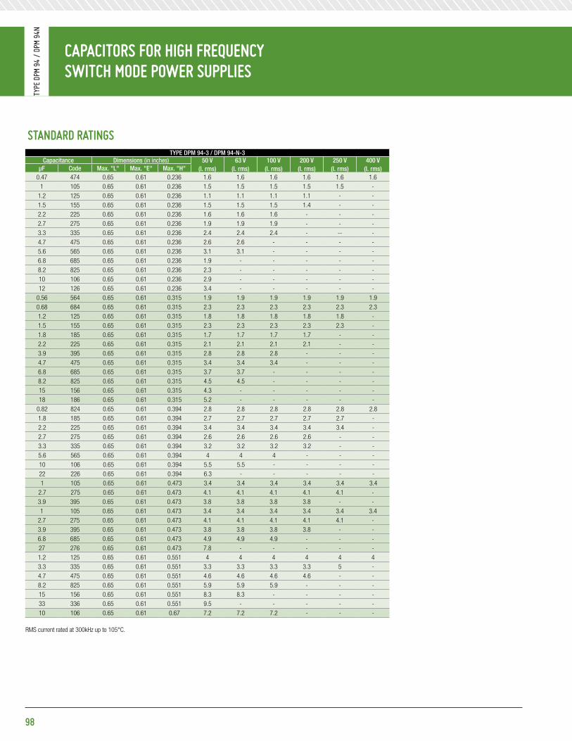
CapaCitors For HiGH FreQuenCy sWitCH Mode poWer supplies
Type
DpM
94
/ Dp
M 94
N
98
standard ratinGstYpe Dpm 94-3 / Dpm 94-n-3
Capacitance Dimensions (in inches) 50 V (i. rms)
63 V (i. rms)
100 V (i. rms)
200 V (i. rms)
250 V (i. rms)
400 V (i. rms)μF Code max. "l" max. "e" max. "h"
0.47 474 0.65 0.61 0.236 1.6 1.6 1.6 1.6 1.6 1.61 105 0.65 0.61 0.236 1.5 1.5 1.5 1.5 1.5 -
1.2 125 0.65 0.61 0.236 1.1 1.1 1.1 1.1 - -1.5 155 0.65 0.61 0.236 1.5 1.5 1.5 1.4 - -2.2 225 0.65 0.61 0.236 1.6 1.6 1.6 - - -2.7 275 0.65 0.61 0.236 1.9 1.9 1.9 - - -3.3 335 0.65 0.61 0.236 2.4 2.4 2.4 - -- -4.7 475 0.65 0.61 0.236 2.6 2.6 - - - -5.6 565 0.65 0.61 0.236 3.1 3.1 - - - -6.8 685 0.65 0.61 0.236 1.9 - - - - -8.2 825 0.65 0.61 0.236 2.3 - - - - -10 106 0.65 0.61 0.236 2.9 - - - - -12 126 0.65 0.61 0.236 3.4 - - - - -
0.56 564 0.65 0.61 0.315 1.9 1.9 1.9 1.9 1.9 1.90.68 684 0.65 0.61 0.315 2.3 2.3 2.3 2.3 2.3 2.31.2 125 0.65 0.61 0.315 1.8 1.8 1.8 1.8 1.8 -1.5 155 0.65 0.61 0.315 2.3 2.3 2.3 2.3 2.3 -1.8 185 0.65 0.61 0.315 1.7 1.7 1.7 1.7 - -2.2 225 0.65 0.61 0.315 2.1 2.1 2.1 2.1 - -3.9 395 0.65 0.61 0.315 2.8 2.8 2.8 - - -4.7 475 0.65 0.61 0.315 3.4 3.4 3.4 - - -6.8 685 0.65 0.61 0.315 3.7 3.7 - - - -8.2 825 0.65 0.61 0.315 4.5 4.5 - - - -15 156 0.65 0.61 0.315 4.3 - - - - -18 186 0.65 0.61 0.315 5.2 - - - - -
0.82 824 0.65 0.61 0.394 2.8 2.8 2.8 2.8 2.8 2.81.8 185 0.65 0.61 0.394 2.7 2.7 2.7 2.7 2.7 -2.2 225 0.65 0.61 0.394 3.4 3.4 3.4 3.4 3.4 -2.7 275 0.65 0.61 0.394 2.6 2.6 2.6 2.6 - -3.3 335 0.65 0.61 0.394 3.2 3.2 3.2 3.2 - -5.6 565 0.65 0.61 0.394 4 4 4 - - -10 106 0.65 0.61 0.394 5.5 5.5 - - - -22 226 0.65 0.61 0.394 6.3 - - - - -1 105 0.65 0.61 0.473 3.4 3.4 3.4 3.4 3.4 3.4
2.7 275 0.65 0.61 0.473 4.1 4.1 4.1 4.1 4.1 -3.9 395 0.65 0.61 0.473 3.8 3.8 3.8 3.8 - -1 105 0.65 0.61 0.473 3.4 3.4 3.4 3.4 3.4 3.4
2.7 275 0.65 0.61 0.473 4.1 4.1 4.1 4.1 4.1 -3.9 395 0.65 0.61 0.473 3.8 3.8 3.8 3.8 - -6.8 685 0.65 0.61 0.473 4.9 4.9 4.9 - - -27 276 0.65 0.61 0.473 7.8 - - - - -1.2 125 0.65 0.61 0.551 4 4 4 4 4 43.3 335 0.65 0.61 0.551 3.3 3.3 3.3 3.3 5 -4.7 475 0.65 0.61 0.551 4.6 4.6 4.6 4.6 - -8.2 825 0.65 0.61 0.551 5.9 5.9 5.9 - - -15 156 0.65 0.61 0.551 8.3 8.3 - - - -33 336 0.65 0.61 0.551 9.5 - - - - -10 106 0.65 0.61 0.67 7.2 7.2 7.2 - - -
RMS current rated at 300kHz up to 105°C.

CapaCitors For HiGH FreQuenCy sWitCH Mode poWer supplies
Type
DpM
94
/ Dp
M 94
N
99
standard ratinGstYpe Dpm 94-4 / Dpm 94-n-4
Capacitance Dimensions (in inches) 50 V (i. rms)
63 V (i. rms)
100 V (i. rms)
200 V (i. rms)
250 V (i. rms)
400 V (i. rms)μF Code max. "l" max. "e" max. "h"
0.47 474 0.728 0.67 0.236 1.3 1.3 1.3 1.3 1.3 1.30.56 564 0.728 0.67 0.236 1.6 1.6 1.6 1.6 1.6 1.60.68 684 0.728 0.67 0.236 2 2 2 2 2 2
1 105 0.728 0.67 0.236 1.3 1.3 1.3 1.3 1.3 -1.2 125 0.728 0.67 0.236 1.6 1.6 1.6 1.6 1.6 -1.5 155 0.728 0.67 0.236 2 2 2 2 2 -1.8 185 0.728 0.67 0.236 1.6 1.6 1.6 1.6 -- -2.2 225 0.728 0.67 0.236 2 2 2 2 - -3.3 335 0.728 0.67 0.236 2.1 2.1 2.1 - - -3.9 395 0.728 0.67 0.236 2.5 2.5 2.5 - - -6.8 685 0.728 0.67 0.236 3.4 3.4 - - - -10 106 0.728 0.67 0.236 2.6 - - - - -12 126 0.728 0.67 0.236 3.1 - - - - -15 156 0.728 0.67 0.236 3.9 - - - - -
0.82 824 0.728 0.67 0.315 2.5 2.5 2.5 2.5 2.5 2.51.8 185 0.728 0.67 0.315 2.4 2.4 2.4 2.4 2.4 -2.2 225 0.728 0.67 0.315 3 3 3 3 3 -2.7 275 0.728 0.67 0.315 2.4 2.4 2.4 2.4 - -4.7 475 0.728 0.67 0.315 3 3 3 - - -5.6 565 0.728 0.67 0.315 3.6 3.6 3.6 - - -8.2 825 0.728 0.67 0.315 4 4 - - - -10 106 0.728 0.67 0.315 4.9 4.9 - - - -18 186 0.728 0.67 0.315 4.6 - - - - -22 226 0.728 0.67 0.315 5.7 - - - - -1 104 0.728 0.67 0.394 3 3 3 3 3 3
1.2 125 0.728 0.67 0.394 3.6 3.6 3.6 3.6 3.6 3.62.7 275 0.728 0.67 0.394 3.6 3.6 3.6 3.6 3.6 -3.3 335 0.728 0.67 0.394 3 3 3 3 4.4 -3.9 395 0.728 0.67 0.394 3.5 3.5 3.5 3.5 - -6.8 685 0.728 0.67 0.394 4.3 4.3 4.3 - - -8.2 825 0.728 0.67 0.394 5.2 5.2 5.2 - - -12 126 0.728 0.67 0.394 5.9 5.9 - - - -27 276 0.728 0.67 0.394 7 - - - - -1.5 155 0.728 0.67 0.473 4.5 4.5 4.5 4.5 4.5 4.53.9 395 0.728 0.67 0.473 5.3 5.3 5.3 5.3 5.3 -4.7 475 0.728 0.67 0.473 4.3 4.3 4.3 4.3 - -10 106 0.728 0.67 0.473 6.4 6.4 6.4 - - -15 156 0.728 0.67 0.473 7.4 7.4 - - - -33 336 0.728 0.67 0.473 8.5 - - - - -1.8 185 0.728 0.67 0.591 5.4 5.4 5.4 5.4 5.4 5.44.7 475 0.728 0.67 0.591 6.3 6.3 6.3 6.3 6.3 -5.6 565 0.728 0.67 0.591 5.1 5.1 5.1 5.1 - -12 126 0.728 0.67 0.591 7.7 7.7 7.7 - - -18 186 0.728 0.67 0.591 8.9 8.9 - - - -22 226 0.728 0.67 0.591 10 10 - - - -39 396 0.728 0.67 0.591 10 - - - - -47 476 0.728 0.67 0.591 10 - - - - -6.8 685 0.728 0.67 0.67 - - - 6.2 - -
RMS current rated at 300kHz up to 105°C.

CapaCitors For HiGH FreQuenCy sWitCH Mode poWer supplies
Type
DpM
948
100
pHysiCal CHaraCteristiCsConstRuCtion:Dielectric: metallized polyethylene terephtalate. Self healing, low inductance.
Case: Thermoplastic case. Epoxy resin molded.
leaD mateRial: DPM 948 - Surface mount device.
maRking:Dearborn trademark, type or catalog number, capacitance, tolerance and voltage.
eleCtriCal speCiFiCationsopeRating tempeRatuRe Range: -55°C to +105°C
Dissipation FaCtoR: ≤ 0.8% @ 1kHZ CR ≤ 1 μF≤ 1.0% @ 1kHZ CR > 1 μF
insulation ResistanCe:≥ 3,750 MΩ for CR ≤ 0.33 and ≤ 100 V≥ 7,500 MΩ for CR ≤ 0.33 and ≤ 100 V
DieleCtRiC WithstanDing Voltage (DWV): 1.6 x rated voltage
peRmissible CuRRent:@ 300kHz up to 105°C = I. rms @ 300kHz to 125°C = 0.1 I. rms
aVailable CapaCitanCe toleRanCes:±20% & ± 10%
L
H
RS
0.08+ 0.02 - 0
E
E
H
L
X0.10
≥ 0.20
0.02
0.01
voltaGe Gradients (dV / dT in V / s)
model 63 V 100 V 160 V 250 V 400 V 500 V 630 V
DPM 948-1 70 80 130 150 230 370 440
DPM 948-2 40 40 60 70 100 130 170
DPM 948-3 30 40 50 70 100 130 160
DPM 948-4 30 30 50 60 90 120 140
diMensions (in inches)

CapaCitors For HiGH FreQuenCy sWitCH Mode poWer supplies
Type
DpM
948
101
standard ratinGstYpe Dpm 948-1
Capacitance Dimensions (in inches)63 V
(i. rms)100 V
(i. rms)160 V
(i. rms)250 V
(i. rms)400 V
(i. rms)500 V
(i. rms)630 V
(i. rms)μF Code max. "l" max. "e" max. "h"R
± 0.008s
± 0.0080.022 223 0.421 0.421 0.236 0.197 0.06 0.2 0.2 0.2 0.2 0.2 0.2 0.20.027 273 0.421 0.421 0.236 0.197 0.06 0.2 0.2 0.2 0.2 0.2 0.2 0.20.033 333 0.421 0.421 0.236 0.197 0.06 0.2 0.2 0.2 0.2 0.2 0.2 0.30.039 393 0.421 0.421 0.236 0.197 0.06 0.3 0.3 0.3 0.3 0.3 0.3 0.40.047 473 0.421 0.421 0.236 0.197 0.06 0.4 0.4 0.4 0.4 0.4 0.4 -0.056 563 0.421 0.421 0.236 0.197 0.06 0.4 0.4 0.4 0.4 0.4 0.4 -0.068 683 0.421 0.421 0.236 0.197 0.06 0.4 0.4 0.4 0.4 0.4 0.5 -0.082 823 0.421 0.421 0.236 0.197 0.06 0.5 0.5 0.5 0.5 0.5 - -
0.1 104 0.421 0.421 0.236 0.197 0.06 0.6 0.6 0.6 0.6 0.6 - -0.12 124 0.421 0.421 0.236 0.197 0.06 0.7 0.7 0.7 0.7 0.7 - -0.15 154 0.421 0.421 0.236 0.197 0.06 0.9 0.9 0.9 0.9 0.9 - -0.18 184 0.421 0.421 0.236 0.197 0.06 0.3 0.3 0.3 0.3 - - -0.22 224 0.421 0.421 0.236 0.197 0.06 0.4 0.4 0.4 0.4 - - -0.27 274 0.421 0.421 0.236 0.197 0.06 0.5 0.5 0.5 0.5 - - -0.33 334 0.421 0.421 0.236 0.197 0.06 0.5 0.5 0.5 0.6 - - -0.39 394 0.421 0.421 0.236 0.197 0.06 0.6 0.6 0.6 - - - -0.47 474 0.421 0.421 0.236 0.197 0.06 0.7 0.7 0.7 - - - -0.56 564 0.421 0.421 0.236 0.197 0.06 0.7 0.7 0.8 - - - -0.68 684 0.421 0.421 0.236 0.197 0.06 0.8 0.8 - - - - -0.82 824 0.421 0.421 0.236 0.197 0.06 0.9 0.9 - - - - -
1 105 0.421 0.421 0.236 0.197 0.06 1.1 1.2 - - - - -1.2 125 0.421 0.421 0.236 0.197 0.06 1.3 - - - - - -1.5 155 0.421 0.421 0.236 0.197 0.06 1.7 - - - - - -1.8 185 0.421 0.421 0.236 0.197 0.06 2.1 - - - - - -
0.047 473 0.421 0.421 0.315 0.197 0.06 0.5 0.5 0.5 0.5 0.5 0.5 0.50.056 563 0.421 0.421 0.315 0.197 0.06 0.6 0.6 0.6 0.6 0.6 0.6 0.60.082 823 0.421 0.421 0.315 0.197 0.06 0.7 0.7 0.7 0.7 0.7 0.7 -0.1 104 0.421 0.421 0.315 0.197 0.06 0.8 0.8 0.8 0.8 0.8 0.8 -0.18 184 0.421 0.421 0.315 0.197 0.06 1 1 1 1 1 - -0.22 224 0.421 0.421 0.315 0.197 0.06 1.3 1.3 1.3 1.3 1.3 - -0.39 394 0.421 0.421 0.315 0.197 0.06 0.8 0.8 0.8 0.8 - - -0.47 474 0.421 0.421 0.315 0.197 0.06 1 1 1 1 - - -0.68 684 0.421 0.421 0.315 0.197 0.06 1 1 1 - - - -0.82 824 0.421 0.421 0.315 0.197 0.06 1.1 1.1 1.1 - - - -1.2 125 0.421 0.421 0.394 0.197 0.06 1.4 1.4 - - - - -1.5 155 0.421 0.421 0.394 0.197 0.06 1.8 1.8 - - - - -1.8 185 0.421 0.421 0.394 0.197 0.06 2.1 2.1 - - - - -2.2 225 0.421 0.421 0.394 0.197 0.06 2.5 - - - - - -2.7 275 0.421 0.421 0.394 0.197 0.06 3.1 - - - - - -
RMS current rated at 300kHz up to 105°C.

CapaCitors For HiGH FreQuenCy sWitCH Mode poWer supplies
Type
DpM
948
102
standard ratinGstYpe Dpm 948-1
Capacitance Dimensions (in inches)63 V
(i. rms)100 V
(i. rms)160 V
(i. rms)250 V
(i. rms)400 V
(i. rms)500 V
(i. rms)630 V
(i. rms)μF Code max. "l" max. "e" max. "h"R
± 0.008s
± 0.0080.068 683 0.421 0.421 0.394 0.197 0.06 0.7 0.7 0.7 0.7 0.7 0.7 0.70.082 823 0.421 0.421 0.394 0.197 0.06 1 1 1 1 1 1 1
0.1 104 0.421 0.421 0.394 0.197 0.06 1.1 1.1 1.1 1.1 1.1 1.1 1.10.12 124 0.421 0.421 0.394 0.197 0.06 1 1 1 1 1 1 -0.15 154 0.421 0.421 0.394 0.197 0.06 1.2 1.2 1.2 1.2 1.2 1.2 -0.27 274 0.421 0.421 0.394 0.197 0.06 1.6 1.6 1.6 1.6 1.6 - -0.56 564 0.421 0.421 0.394 0.197 0.06 1.1 1.1 1.1 1.1 - - -0.68 684 0.421 0.421 0.394 0.197 0.06 1.4 1.4 1.4 1.4 - - -
1 105 0.421 0.421 0.394 0.197 0.06 1.4 1.4 1.4 - - - -1.2 125 0.421 0.421 0.394 0.197 0.06 1.8 1.8 1.8 - - - -2.2 225 0.421 0.421 0.394 0.197 0.06 2.6 2.6 - - - - -2.7 275 0.421 0.421 0.394 0.197 0.06 3.2 3.2 - - - - -3.3 335 0.421 0.421 0.394 0.197 0.06 3.8 - - - - - -3.9 395 0.421 0.421 0.394 0.197 0.06 4.69 - - - - - -0.12 124 0.421 0.421 0.475 0.197 0.06 1.3 1.3 1.3 1.3 1.3 1.3 1.30.18 184 0.421 0.421 0.475 0.197 0.06 1.4 1.4 1.4 1.4 1.4 1.4 -0.33 334 0.421 0.421 0.475 0.197 0.06 2 2 2 2 2 - -0.39 394 0.421 0.421 0.475 0.197 0.06 2.3 2.3 2.3 2.3 2.3 - -0.82 824 0.421 0.421 0.475 0.197 0.06 1.7 1.7 1.7 1.7 - - -
1 105 0.421 0.421 0.475 0.197 0.06 2.1 2.1 2.1 2.1 - - -1.5 155 0.421 0.421 0.475 0.197 0.06 2.1 2.1 2.1 - - - -1.8 185 0.421 0.421 0.475 0.197 0.06 2.6 2.6 2.6 - - - -3.3 335 0.421 0.421 0.475 0.197 0.06 3.9 3.9 - - - - -4.7 475 0.421 0.421 0.475 0.197 0.06 6 - - - - - -5.6 565 0.421 0.421 0.475 0.197 0.06 7.1 - - - - - -
RMS current rated at 300kHz up to 105°C.

CapaCitors For HiGH FreQuenCy sWitCH Mode poWer supplies
Type
DpM
948
103
standard ratinGstYpe Dpm 948-2
Capacitance Dimensions (in inches)63 V
(i. rms)100 V
(i. rms)160 V
(i. rms)250 V
(i. rms)400 V
(i. rms)500 V
(i. rms)630 V
(i. rms)μF Code max. "l" max. "e" max. "h"R
± 0.008s
± 0.0080.068 683 0.61 0.453 0.236 0.197 0.06 0.3 0.3 0.3 0.3 0.3 0.3 0.30.082 823 0.61 0.453 0.236 0.197 0.06 0.3 0.3 0.3 0.3 0.3 0.3 0.3
0.1 104 0.61 0.453 0.236 0.197 0.06 0.4 0.4 0.4 0.4 0.4 0.4 0.40.12 124 0.61 0.453 0.236 0.197 0.06 0.4 0.4 0.4 0.4 0.4 0.4 0.50.15 154 0.61 0.453 0.236 0.197 0.06 0.5 0.5 0.5 0.5 0.5 0.5 -0.18 184 0.61 0.453 0.236 0.197 0.06 0.5 0.5 0.5 0.5 0.5 0.7 -0.22 224 0.61 0.453 0.236 0.197 0.06 0.6 0.6 0.6 0.6 0.6 0.8 -0.27 274 0.61 0.453 0.236 0.197 0.06 0.8 0.8 0.8 0.8 0.8 - -0.33 334 0.61 0.453 0.236 0.197 0.06 1 1 1 1 1 - -0.47 474 0.61 0.453 0.236 0.197 0.06 0.8 0.8 0.8 0.8 - - -0.56 564 0.61 0.453 0.236 0.197 0.06 0.9 0.9 0.9 0.9 - - -0.68 684 0.61 0.453 0.236 0.197 0.06 1.1 1.1 1.1 1.1 - - -0.82 824 0.61 0.453 0.236 0.197 0.06 0.6 0.6 0.6 1.3 - - -
1 105 0.61 0.453 0.236 0.197 0.06 0.7 0.7 0.7 - - - -1.2 125 0.61 0.453 0.236 0.197 0.06 0.9 0.9 0.9 - - - -1.5 155 0.61 0.453 0.236 0.197 0.06 0.9 0.9 1.1 - - - -1.8 185 0.61 0.453 0.236 0.197 0.06 1.1 1.1 - - - - -2.2 225 0.61 0.453 0.236 0.197 0.06 1.3 1.3 - - - - -2.7 275 0.61 0.453 0.236 0.197 0.06 1.5 1.7 - - - - -3.3 335 0.61 0.453 0.236 0.197 0.06 1.9 - - - - - -3.9 395 0.61 0.453 0.236 0.197 0.06 2.3 - - - - - -0.15 154 0.61 0.453 0.315 0.197 0.06 0.7 0.7 0.7 0.7 0.7 0.7 0.70.18 184 0.61 0.453 0.315 0.197 0.06 1 1 1 1 1 1 10.27 274 0.61 0.453 0.315 0.197 0.06 1 1 1 1 1 1 -0.33 334 0.61 0.453 0.315 0.197 0.06 1.2 1.2 1.2 1.2 1.2 1.2 -0.39 394 0.61 0.453 0.315 0.197 0.06 1.1 1.1 1.1 1.1 1.1 - -0.47 474 0.61 0.453 0.315 0.197 0.06 0.4 1.4 1.4 1.4 1.4 - -
1 105 0.61 0.453 0.315 0.197 0.06 1.6 1.6 1.6 1.6 - - -1.2 125 0.61 0.453 0.315 0.197 0.06 2 2 2 2 - - -1.8 185 0.61 0.453 0.315 0.197 0.06 1.4 1.4 1.4 - - - -2.2 225 0.61 0.453 0.315 0.197 0.06 2.2 2.2 2.2 - - - -3.3 335 0.61 0.453 0.315 0.197 0.06 2 2 - - - - -3.9 395 0.61 0.453 0.315 0.197 0.06 2.4 2.4 - - - - -4.7 475 0.61 0.453 0.315 0.197 0.06 2.8 - - - - - -5.6 565 0.61 0.453 0.315 0.197 0.06 3.3 - - - - - -0.22 224 0.61 0.453 0.394 0.197 0.06 1.1 1.1 1.1 1.1 1.1 1.1 1.10.27 274 0.61 0.453 0.394 0.197 0.06 1.4 1.4 1.4 1.4 1.4 1.4 1.40.39 394 0.61 0.453 0.394 0.197 0.06 1.4 1.4 1.4 1.4 1.4 1.4 -0.47 474 0.61 0.453 0.394 0.197 0.06 1.7 1.7 1.7 1.7 1.7 1.7 -0.56 564 0.61 0.453 0.394 0.197 0.06 1.7 1.7 1.7 1.7 1.7 - -0.68 684 0.61 0.453 0.394 0.197 0.06 2 2 2 2 2 - -1.5 155 0.61 0.453 0.394 0.197 0.06 2.5 2.5 2.5 2.5 - - -1.8 185 0.61 0.453 0.394 0.197 0.06 3 3 3 3 - - -2.7 275 0.61 0.453 0.394 0.197 0.06 2.1 2.1 2.1 - - - -3.3 335 0.61 0.453 0.394 0.197 0.06 2.5 2.5 2.5 - - - -4.7 475 0.61 0.453 0.394 0.197 0.06 2.8 2.8 - - - - -5.6 565 0.61 0.453 0.394 0.197 0.06 3.4 3.4 - - - - -6.8 685 0.61 0.453 394 0.197 0.06 4 - - - - - -8.2 825 0.61 0.453 0.394 0.197 0.06 4.8 - - - - - -
RMS current rated at 300kHz up to 105°C.

CapaCitors For HiGH FreQuenCy sWitCH Mode poWer supplies
Type
DpM
948
104
standard ratinGstYpe Dpm 948-3
Capacitance Dimensions (in inches)63 V
(i. rms)100 V
(i. rms)160 V
(i. rms)250 V
(i. rms)400 V
(i. rms)500 V
(i. rms)630 V
(i. rms)μF Code max. "l" max. "e" max. "h"R
± 0.008s
± 0.0080.12 124 0.65 0.61 0.236 0.276 0.08 0.5 0.5 0.5 0.5 0.5 0.5 0.50.15 154 0.65 0.61 0.236 0.276 0.08 0.6 0.6 0.6 0.6 0.6 0.6 0.60.18 184 0.65 0.61 0.236 0.276 0.08 0.7 0.7 0.7 0.7 0.7 0.7 0.70.22 224 0.65 0.61 0.236 0.276 0.08 0.7 0.7 0.7 0.7 0.7 0.7 -0.27 274 0.65 0.61 0.236 0.276 0.08 0.9 0.9 0.9 0.9 0.9 0.9 -0.33 334 0.65 0.61 0.236 0.276 0.08 0.9 0.9 0.9 0.9 0.9 - -0.39 394 0.65 0.61 0.236 0.276 0.08 1 1 1 1 1 - -0.47 474 0.65 0.61 0.236 0.276 0.08 1.3 1.3 1.3 1.3 1.3 - -0.82 824 0.65 0.61 0.236 0.276 0.08 0.7 0.7 0.7 0.7 - - -
1 105 0.65 0.61 0.236 0.276 0.08 0.9 0.9 0.9 0.9 - - -1.2 125 0.65 0.61 0.236 0.276 0.08 1.1 1.1 1.1 1.1 - - -1.5 155 0.65 0.61 0.236 0.276 0.08 1 1 1 - - - -1.8 185 0.65 0.61 0.236 0.276 0.08 1.3 1.3 1.3 - - - -2.2 225 0.65 0.61 0.236 0.276 0.08 1.6 1.6 1.6 - - - -2.7 275 0.65 0.61 0.236 0.276 0.08 1.5 1.5 - - - - -3.3 335 0.65 0.61 0.236 0.276 0.08 1.8 1.9 - - - - -3.9 395 0.65 0.61 0.236 0.276 0.08 2.1 2.2 - - - - -4.7 475 0.65 0.61 0.236 0.276 0.08 2.6 - - - - - -5.6 565 0.65 0.61 0.236 0.276 0.08 3.1 - - - - - -0.22 224 0.65 0.61 0.315 0.276 0.08 0.9 0.9 0.9 0.9 0.9 0.9 0.90.27 274 0.65 0.61 0.315 0.276 0.08 1.1 1.1 1.1 1.1 1.1 1.1 1.10.33 334 0.65 0.61 0.315 0.276 0.08 1.1 1.1 1.1 1.1 1.1 1.1 1.30.39 394 0.65 0.61 0.315 0.276 0.08 1.3 1.3 1.3 1.3 1.3 1.3 -0.47 474 0.65 0.61 0.315 0.276 0.08 1.6 1.6 1.6 1.6 1.6 1.6 -0.56 564 0.65 0.61 0.315 0.276 0.08 1.5 1.5 1.5 1.5 1.5 - -0.68 684 0.65 0.61 0.315 0.276 0.08 1.8 1.8 1.8 1.8 1.8 - -0.82 824 0.65 0.61 0.315 0.276 0.08 2.2 2.2 2.2 2.2 2.2 - -1.5 155 0.65 0.61 0.315 0.276 0.08 1.4 1.4 1.4 1.4 - - -1.8 185 0.65 0.61 0.315 0.276 0.08 1.7 1.7 1.7 1.7 - - -2.2 225 0.65 0.61 0.315 0.276 0.08 2.1 2.1 2.1 2.1 - - -2.7 275 0.65 0.61 0.315 0.276 0.08 1.9 1.9 1.9 - - - -3.3 335 0.65 0.61 0.315 0.276 0.08 2.4 2.4 2.4 - - - -4.7 475 0.65 0.61 0.315 0.276 0.08 2.7 2.7 - - - - -5.6 565 0.65 0.61 0.315 0.276 0.08 3.2 3.2 - - - - -6.8 685 0.65 0.61 0.315 0.276 0.08 3.7 - - - - - -8.2 825 0.65 0.61 0.315 0.276 0.08 4.5 - - - - - -0.39 394 0.65 0.61 0.394 0.276 0.08 1.6 1.6 1.6 1.6 1.6 1.6 1.60.56 564 0.65 0.61 0.394 0.276 0.08 1.9 1.9 1.9 1.9 1.9 1.9 -0.68 684 0.65 0.61 0.394 0.276 0.08 2.3 2.3 2.3 2.3 2.3 2.3 -
1 105 0.65 0.61 0.394 0.276 0.08 2.7 2.7 2.7 2.7 2.7 - -1.2 125 0.65 0.61 0.394 0.276 0.08 3.2 3.2 3.2 3.2 3.2 - -2.7 275 0.65 0.61 0.394 0.276 0.08 2.6 2.6 2.6 2.6 - - -3.9 395 0.65 0.61 0.394 0.276 0.08 2.8 2.8 2.8 - - -4.7 475 0.65 0.61 0.394 0.276 0.08 3.4 3.4 3.4 - - - -6.8 685 0.65 0.61 0.394 0.276 0.08 3.2 3.2 - - - -8.2 825 0.65 0.61 0.394 0.276 0.08 4.7 4.7 - - - - -10 106 0.65 0.61 0.394 0.276 0.08 5.5 - - - - -12 126 0.65 0.61 0.394 0.276 0.08 6.6 - - - - - -
RMS current rated at 300kHz up to 105°C.

CapaCitors For HiGH FreQuenCy sWitCH Mode poWer supplies
Type
DpM
948
105
standard ratinGstYpe Dpm 948-3
Capacitance Dimensions (in inches)63 V
(i. rms)100 V
(i. rms)160 V
(i. rms)250 V
(i. rms)400 V
(i. rms)500 V
(i. rms)630 V
(i. rms)μF Code max. "l" max. "e" max. "h"R
± 0.008s
± 0.0080.47 474 0.65 0.61 0.473 0.276 0.08 2 2 2 2 2 2 20.56 564 0.65 0.61 0.473 0.276 0.08 2.4 2.4 2.4 2.4 2.4 2.4 2.40.82 824 0.65 0.61 0.473 0.276 0.08 2.8 2.8 2.8 2.8 2.8 2.8 -3.3 335 0.65 0.61 0.473 0.276 0.08 3.2 3.2 3.2 3.2 - - -5.6 565 0.65 0.61 0.473 0.276 0.08 4 4 4 - - - -10 106 0.65 0.61 0.473 0.276 0.08 5.7 5.7 - - - - -15 156 0.65 0.61 0.473 0.276 0.08 8.3 - - - - - -1 106 0.65 0.61 0.551 0.276 0.08 3.4 3.4 3.4 3.4 3.4 3.4 -
1.5 155 0.65 0.61 0.551 0.276 0.08 4 4 4 4 4 - -1.8 185 0.65 0.61 0.551 0.276 0.08 4.8 4.8 4.8 4.8 4.8 - -3.9 395 0.65 0.61 0.551 0.276 0.08 3.8 3.8 3.8 3.8 - - -6.8 685 0.65 0.61 0.551 0.276 0.08 4.9 4.9 4.9 - - - -12 126 0.65 0.61 0.551 0.276 0.08 6.8 6.8 - - - - -18 186 0.65 0.61 0.551 0.276 0.08 9.9 - - - - - -
0.68 684 0.65 0.61 0.67 0.276 0.059 2.9 2.9 2.9 2.9 2.9 2.9 2.91.2 125 0.65 0.61 0.67 0.276 0.08 4 4 4 4 4 4 -2.2 225 0.65 0.61 0.67 0.276 0.08 5.9 5.9 5.9 5.9 5.9 - -4.7 475 0.65 0.61 0.67 0.276 0.08 4.6 4.6 4.6 4.6 - - -8.2 825 0.65 0.61 0.67 0.276 0.08 5.9 5.9 5.9 - - - -15 156 0.65 0.61 0.67 0.276 0.08 8.5 8.5 - - - - -22 226 0.65 0.61 0.67 0.276 0.08 12.1 - - - - - -
RMS current rated at 300kHz up to 105°C.

CapaCitors For HiGH FreQuenCy sWitCH Mode poWer supplies
Type
DpM
948
106
standard ratinGstYpe Dpm 948-4
Capacitance Dimensions (in inches)63 V
(i. rms)100 V
(i. rms)160 V
(i. rms)250 V
(i. rms)400 V
(i. rms)500 V
(i. rms)630 V
(i. rms)μF Code max. "l" max. "e" max. "h"R
± 0.008s
± 0.0080.18 184 0.728 0.67 0.236 0.276 0.08 0.6 0.6 0.6 0.6 0.6 0.6 0.60.22 224 0.728 0.67 0.236 0.276 0.08 0.7 0.7 0.7 0.7 0.7 0.7 0.70.27 274 0.728 0.67 0.236 0.276 0.08 0.7 0.7 0.7 0.7 0.7 0.7 -0.33 334 0.728 0.67 0.236 0.276 0.08 0.9 0.9 0.9 0.9 0.9 0.9 -0.39 394 0.728 0.67 0.236 0.276 0.08 1.1 1.1 1.1 1.1 1.1 1.1 -0.47 474 0.728 0.67 0.236 0.276 0.08 1 1 1 1 1 - -0.56 564 0.728 0.67 0.236 0.276 0.08 1.3 1.3 1.3 1.3 1.3 - -1.2 125 0.728 0.67 0.236 0.276 0.08 1 1 1 1 - - -1.5 155 0.728 0.67 0.236 0.276 0.08 1.3 1.3 1.3 1.3 - - -2.2 225 0.728 0.67 0.236 0.276 0.08 1.4 1.4 1.4 - - - -2.7 275 0.728 0.67 0.236 0.276 0.08 1.7 1.7 1.7 - - - -3.9 395 0.728 0.67 0.236 0.276 0.08 2 2 - - - - -4.7 475 0.728 0.67 0.236 0.276 0.08 2.3 2.4 - - - - -5.6 565 0.728 0.67 0.236 0.276 0.08 2.8 - - - - - -6.8 685 0.728 0.67 0.236 0.276 0.08 3.4 - - - - - -0.27 274 0.728 0.67 0.315 0.276 0.08 0.9 0.9 0.9 0.9 0.9 0.9 0.90.33 334 0.728 0.67 0.315 0.276 0.08 1.1 1.1 1.1 1.1 1.1 1.1 1.10.47 474 0.728 0.67 0.315 0.276 0.08 1.3 1.3 1.3 1.3 1.3 1.3 -0.56 564 0.728 0.67 0.315 0.276 0.08 1.6 1.6 1.6 1.6 1.6 1.6 -0.68 684 0.728 0.67 0.315 0.276 0.08 1.6 1.6 1.6 1.6 1.6 2 -0.82 824 0.728 0.67 0.315 0.276 0.08 2 2 2 2 2 - -1.8 185 0.728 0.67 0.315 0.276 0.08 1.6 1.6 1.6 1.6 - - -2.2 225 0.728 0.67 0.315 0.276 0.08 2 2 2 2 - - -3.3 335 0.728 0.67 0.315 0.276 0.08 2.1 2.1 2.1 - - - -3.9 395 0.728 0.67 0.315 0.276 0.08 2.5 2.5 2.5 - - - -5.6 565 0.728 0.67 0.315 0.276 0.08 2.9 2.9 - - - -6.8 685 0.728 0.67 0.315 0.276 0.08 3.4 3.4 - - - - -8.2 825 0.728 0.67 0.315 0.276 0.08 4 4.2 - - - - -10 106 0.728 0.67 0.315 0.276 0.08 4.9 - - - - - -
0.39 394 0.728 0.67 0.394 0.276 0.08 1.4 1.4 1.4 1.4 1.4 1.4 1.40.47 474 0.728 0.67 0.394 0.276 0.08 1.6 1.6 1.6 1.6 1.6 1.6 1.60.82 824 0.728 0.67 0.394 0.276 0.08 2.5 2.5 2.5 2.5 2.5 2.5 -
1 105 0.728 0.67 0.394 0.276 0.08 2.4 2.4 2.4 2.4 2.4 - -1.2 125 0.728 0.67 0.394 0.276 0.08 2.9 2.9 2.9 2.9 2.9 - -2.7 275 0.728 0.67 0.394 0.276 0.08 2.4 2.4 2.4 2.4 - - -3.3 335 0.728 0.67 0.394 0.276 0.08 3 3 3 3 - - -4.7 475 0.728 0.67 0.394 0.276 0.08 3 3 3 - - - -5.6 565 0.728 0.67 0.394 0.276 0.08 3.6 3.6 3.6 - - - -10 106 0.728 0.67 0.394 0.276 0.08 5.1 5.1 - - - - -12 126 0.728 0.67 0.394 0.276 0.08 5.9 - - - - - -15 156 0.728 0.67 0.394 0.276 0.08 7.4 - - - - - -
RMS current rated at 300kHz up to 105°C.
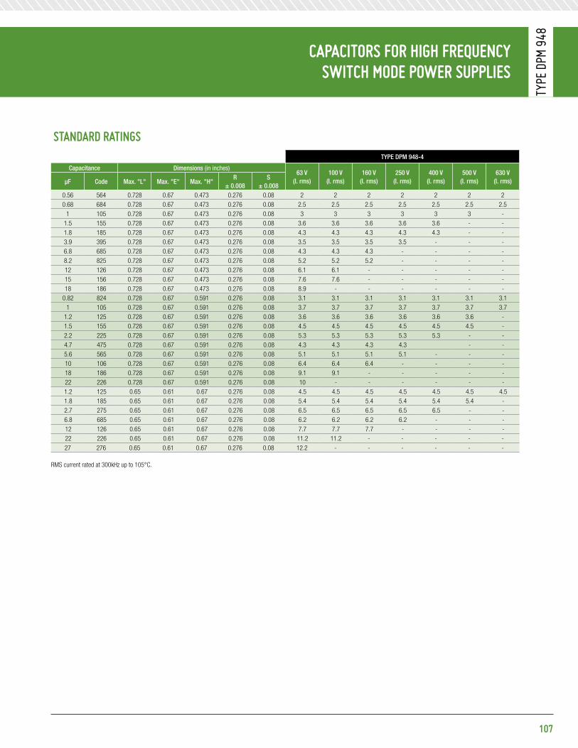
CapaCitors For HiGH FreQuenCy sWitCH Mode poWer supplies
Type
DpM
948
107
standard ratinGstYpe Dpm 948-4
Capacitance Dimensions (in inches)63 V
(i. rms)100 V
(i. rms)160 V
(i. rms)250 V
(i. rms)400 V
(i. rms)500 V
(i. rms)630 V
(i. rms)μF Code max. "l" max. "e" max. "h"R
± 0.008s
± 0.0080.56 564 0.728 0.67 0.473 0.276 0.08 2 2 2 2 2 2 20.68 684 0.728 0.67 0.473 0.276 0.08 2.5 2.5 2.5 2.5 2.5 2.5 2.5
1 105 0.728 0.67 0.473 0.276 0.08 3 3 3 3 3 3 -1.5 155 0.728 0.67 0.473 0.276 0.08 3.6 3.6 3.6 3.6 3.6 - -1.8 185 0.728 0.67 0.473 0.276 0.08 4.3 4.3 4.3 4.3 4.3 - -3.9 395 0.728 0.67 0.473 0.276 0.08 3.5 3.5 3.5 3.5 - - -6.8 685 0.728 0.67 0.473 0.276 0.08 4.3 4.3 4.3 - - - -8.2 825 0.728 0.67 0.473 0.276 0.08 5.2 5.2 5.2 - - - -12 126 0.728 0.67 0.473 0.276 0.08 6.1 6.1 - - - - -15 156 0.728 0.67 0.473 0.276 0.08 7.6 7.6 - - - - -18 186 0.728 0.67 0.473 0.276 0.08 8.9 - - - - - -
0.82 824 0.728 0.67 0.591 0.276 0.08 3.1 3.1 3.1 3.1 3.1 3.1 3.11 105 0.728 0.67 0.591 0.276 0.08 3.7 3.7 3.7 3.7 3.7 3.7 3.7
1.2 125 0.728 0.67 0.591 0.276 0.08 3.6 3.6 3.6 3.6 3.6 3.6 -1.5 155 0.728 0.67 0.591 0.276 0.08 4.5 4.5 4.5 4.5 4.5 4.5 -2.2 225 0.728 0.67 0.591 0.276 0.08 5.3 5.3 5.3 5.3 5.3 - -4.7 475 0.728 0.67 0.591 0.276 0.08 4.3 4.3 4.3 4.3 - -5.6 565 0.728 0.67 0.591 0.276 0.08 5.1 5.1 5.1 5.1 - - -10 106 0.728 0.67 0.591 0.276 0.08 6.4 6.4 6.4 - - - -18 186 0.728 0.67 0.591 0.276 0.08 9.1 9.1 - - - - -22 226 0.728 0.67 0.591 0.276 0.08 10 - - - - - -1.2 125 0.65 0.61 0.67 0.276 0.08 4.5 4.5 4.5 4.5 4.5 4.5 4.51.8 185 0.65 0.61 0.67 0.276 0.08 5.4 5.4 5.4 5.4 5.4 5.4 -2.7 275 0.65 0.61 0.67 0.276 0.08 6.5 6.5 6.5 6.5 6.5 - -6.8 685 0.65 0.61 0.67 0.276 0.08 6.2 6.2 6.2 6.2 - - -12 126 0.65 0.61 0.67 0.276 0.08 7.7 7.7 7.7 - - - -22 226 0.65 0.61 0.67 0.276 0.08 11.2 11.2 - - - - -27 276 0.65 0.61 0.67 0.276 0.08 12.2 - - - - - -
RMS current rated at 300kHz up to 105°C.

Wrap-and-Fill polyesterdieleCtriC FilM / Foil ConstruCtion
Type
410
p
Voltage DeRating:• At +105°C, 70% of the 85°C rating • At +125°C, 50% of the 85°C rating
Voltage test: 200% of rated voltage for 1 minute
insulation ResistanCe:• At +25°C, 50,000 Megaohm-Microfarads, need not exceed 100,000 Megaohms• At +85°C, 2,500 Megaohm-Microfarads, need not exceed 5,000 Megaohms• At +105°C, 1,000 Megaohm-Microfarads, need not exceed 2,000 Megaohms• At +125°C, 10 Megaohm-Microfarads, need not exceed 150 Megaohms
MaXiMuM pulse rise tiMeCapacitor
length (inch)
Rise time dv / dt (V / μs)
50 VDC 100 VDC 200 VDC 400 VDC 600 VDC
0.450 - 1000 - - -0.531 735 - - - -0.594 540 - - - -0.656 360 - - - -0.718 288 288 413 875 15630.750 275 - - - -0.812 252 - - - -0.844 - 219 268 620 10500.875 - - - - 10180.969 - - 217 - -1.000 - - 180 475 7641.062 161 - - - -1.250 - 127 160 329 5151.375 124 - - - -1.562 - 114 137 310 3591.625 110 - - - -1.750 - - 124 290 -1.875 100 - 110 - -1.937 - 100 - 250 3442.125 75 - - - 3162.375 - 90 100 185 2612.625 - 74 90 - 2343.062 - - 83 - -
diMensions (in inches)
108
Features• Extended Foil Construction • Moisture Resistant
pHysiCal CHaraCteristiCsConstRuCtion:Non-inductive wound polyester film and foil.
Case: Flame retardant tape wrap and epoxy endfill.
leaD mateRial: Solder coated solid wire.
leaD WiRe sizes:
Case Dia. lead aWg
≤ 0.437 0.025 (No. 22)
> 0.437 0.032 (No. 20)
leaD stRength:Capable of withstanding a five pound pull force on lead axis.
maRking:Dearborn trademark, type or catalog number, capacitance, tolerance and voltage.
eleCtriCal speCiFiCationsCapaCitanCe Range: 0.001 μF to 5.0 μF
Voltage Rating:• 50 VDC to 600 VDC • 32 VAC to 220 VAC
CapaCitanCe toleRanCe: ±20%, ±10%, ±5%
opeRating tempeRatuRe: -55°C to +125°C
Dissipation FaCtoR: 1.0%, maximum
DMax.
1.625Min.
1.625Min.
Max.L
Solid tinned wire*
* Leads to be within ±0.062” of center line at egress, but not less than 0.031” from edge.

standard ratinGs
CapacitanceVoltage Code 050 50 VDC / 32 VaC*
Voltage Code 100100 VDC / 63 VaC*
Voltage Code 200200 VDC / 126 VaC*
Voltage Code 400400 VDC / 200 VaC*
Voltage Code 600600 VDC / 220 VaC*
μF Code D l D l D l D l D l0.0010 102 - - - - 0.190 0.450 0.190 0.718 0.190 0.7180.0015 152 - - - - 0.190 0.450 0.190 0.718 0.190 0.7180.0022 222 - - - - 0.190 0.450 0.190 0.718 0.190 0.7180.0033 332 - - - - 0.190 0.450 0.190 0.718 0.205 0.7180.0047 472 - - - - 0.190 0.450 0.190 0.718 0.235 0.7180.0068 682 - - 0.190 0.450 0.190 0.718 0.190 0.718 0.240 0.8440.010 103 - - 0.190 0.450 0.190 0.718 0.200 0.844 0.270 0.8440.015 153 0.190 0.531 0.190 0.718 0.190 0.718 0.230 0.844 0.315 0.8750.022 223 0.200 0.594 0.190 0.718 0.190 0.718 0.265 0.844 0.375 0t.8750.033 333 0.210 0.656 0.190 0.718 0.190 0.844 0.315 0.875 0.395 1.0000.047 413 0.215 0.718 0.215 0.718 0.210 0.844 0.325 1.000 0.400 1.2500.068 683 0.250 0.718 0.215 0.844 0.240 0.844 0.340 1.250 0.455 1.2500.10 104 0.290 0.750 0.245 0.844 0.275 0.969 0.400 1.250 0.470 1.5620.15 154 0.312 0.812 0.285 0.844 0.345 1.000 0.405 1.562 0.545 1.5620.22 224 0.315 1.062 0.290 1.250 0.355 1.250 0.480 1.562 0.590 1.9370.33 334 0.375 1.062 0.325 1.250 0.425 1.250 0.650 1.750 0.800 1.9370.47 474 0.430 1.062 0.380 1.250 0.440 1.562 0.725 1.937 0.890 2.1250.68 689 0.450 1.375 0.455 1.562 0.610 1.750 0.750 2.375 0.980 2.3751.00 105 0.500 1.375 0.535 1.562 0.710 1.875 0.900 2.375 - -1.50 155 0.640 1.625 0.645 1.937 0.730 2.375 - - - -2.00 205 0.730 1.625 0.715 1.937 0.800 2.375 - - - -2.50 255 0.750 1.875 0.715 2.375 0.834 2.625 - - - -3.00 305 0.830 1.875 0.770 2.375 0.905 2.625 - - - -4.00 405 0.850 2.125 0.830 2.625 0.945 3.062 - - - -5.00 505 0.940 2.125 0.915 2.625 - - - - - -
Additional capacitance values, voltages, and tolerances are available upon request.
* AC voltage rating is at 60Hz 1.4 x VRMS + VDC should not exceed the rated VDC.
109
Wrap-and-Fill polyesterdieleCtriC FilM / Foil ConstruCtion
Type
410
p

Wrap-and-Fill HiGH Current Metalized polypropylene FilM CapaCitors
Type
709
G
eleCtriCal speCiFiCationsCapaCitanCe Range: 0.001 μF to 4.7 μF
Voltage Rating:• 160 VDC to 2,000 VDC • 100 VRMS to 700 VRMS
CapaCitanCe toleRanCe: ±20%, ±10%, ±5%
opeRating tempeRatuRe: -55°C to +105°C
Voltage DeRating: At +105°C, 70% of the 85°C rating
Dissipation FaCtoR: 0.03% maximum
DC Voltage test: 160% of rated voltage for 10 sec.
insulation ResistanCe:Measure at 100 VDC after a 2 minute charge.
• At +25°C, 200,000 Megaohm-Microfarads, need not exceed 400,000 Megaohms
MaXiMuM pulse rise tiMe
Capacitor length (inch)
Rise time dv / dt (V / μs)
160 VDC
250 VDC
400 VDC
630 VDC
1,000 VDC
1,600 VDC
2,000 VDC
0.670 900 1140 1840 - - - -0.870 450 560 910 3430 - - -1.140 260 320 520 2120 2800 3800 62001.340 202 240 400 1524 2000 2680 42001.750 140 170 280 980 1280 1690 2600
diMensions (in inches)
110
Features• AC voltage rating to 700 V • DC voltage rating to 2,000 V • High current • High pulse operations
majoR appliCations:Snubber and SCR commutating circuits, protection circuits, input and output filtering, blocking, timing and integrating circuits.
pHysiCal CHaraCteristiCsConstRuCtion:Extended double-sided metalized polyester film, internal series connection (630 to 2,000 VDC), double-sided metalized polyester carrier film.
DieleCtRiC: Polypropylene film.
eleCtRoDes: Vacuum deposited aluminum.
Case: Flame retardant tape wrap and epoxy endfill.
leaD mateRial: Solder coated copper wire.
leaD WiRe sizes:
Case Dia. lead aWg
< 0.300 No. 22
< 0.60 No. 20
0.650 and over No. 18
leaD pull: 5 lbs (2.3 kg) for one minute. No physical damage.
leaD benD: After three complete consecutive bends. No damage.
maRking:Dearborn trademark, type or catalog number, capacitance, tolerance and voltage.
G-ForCePower caPaciTors
DMax.
1.750Min.
1.750Min.
Max.L
Solid tinned wire*
* Leads to be within ±0.062” of center line at egress, but not less than 0.031” from edge.

standard ratinGs
CapacitanceVoltage Code 160 160 VDC / 100 VaC
Voltage Code 250250 VDC / 160 VaC
Voltage Code 400400 VDC / 200 VaC
Voltage Code 630630 VDC / 400 VaC
Voltage Code 1k01,000 VDC / 600 VaC
Voltage Code 1k61,600 VDC / 650 VaC
Voltage Code 2k02,000 VDC / 700 VaC
μF Code D l D l D l D l D l D l D l0.0010 102 - - - - - - - - - - - - 0.256 1.1420.0015 152 - - - - - - - - - - - - 0.256 1.1420.0022 222 - - - - - - - - - - - - 0.256 1.1420.0033 332 - - - - - - - - - - - - 0.276 1.1420.0047 472 - - - - - - - - - - - - 0.315 1.1420.0068 682 - - - - - - - - - - 0.374 1.1420.010 103 - - - - 0.236 0.670 0.276 0.866 0.256 1.142 0.315 1.142 0.433 1.1420.015 153 - - - - 0.256 0.670 0.315 0.866 0.315 1.142 0.315 1.142 0.433 1.1420.022 223 - - 0.236 0.670 0.295 0.670 0.375 0.866 0.354 1.142 0.433 1.142 0.512 1.3390.033 333 0.236 0.670 0.276 0.670 0.276 0.866 0.354 1.140 0.433 1.142 0.452 1.339 0.630 1.3390.047 473 0.256 0.670 0.315 0.670 0.315 0.866 0.413 1.140 0.433 1.339 0.532 1.339 0.591 1.7320.068 683 0.295 0.670 0.276 0.866 0.354 0.866 0.492 1.140 0.512 1.339 0.630 1.339 0.709 1.7320.10 104 0.276 0.866 0.315 0.866 0.433 0.866 0.492 1.340 0.610 1.339 0.591 1.732 0.827 1.7320.15 154 0.315 0.866 0.375 0.866 0.394 1.140 0.591 1.340 0.591 1.732 0.728 1.732 - -0.22 224 0.375 0.866 0.354 1.140 0.472 1.140 0.571 1.730 0.709 1.732 0.866 1.732 - -0.33 334 0.354 1.140 0.413 1.140 0.532 1.140 0.689 1.730 - - - - - -0.47 474 0.394 1.140 0.472 1.140 0.591 1.340 0.827 1.730 - - - - - -0.68 684 0.472 1.140 0.512 1.340 0.689 1.340 0.984 1.730 - - - - - -1.00 105 0.492 1.340 0.610 1.340 0.689 1.730 - - - - - - - -1.50 155 0.610 1.340 0.610 1.730 0.846 1.730 - - - - - - - -2.20 225 0.610 1.730 0.728 1.730 1.024 1.730 - - - - - - - -3.30 335 0.728 1.730 0.886 1.730 - - - - - - - - - -4.70 475 0.866 1.730 - - - - - - - - - - - -
111
Wrap-and-Fill HiGH CurrentMetalized polypropylene FilM CapaCitors
Type
709
G

Wrap-and-Fill HiGH Current Metalized polypropylene FilM CapaCitors
Type
709
G
112
Voltage Vs. FReQuenCY tYpe 709g 160 VDC / 100 VaC
Voltage Vs. FReQuenCY tYpe 709g 400 VDC / 200 VaC
Voltage Vs. FReQuenCY tYpe 709g 250 VDC / 160 VaC
Voltage Vs. FReQuenCY tYpe 709g 630 VDC / 400 VaC
0.22 µF
2.2 µF
1.0 µF
VRMS
10
11,000 10,000 100,000
VOLTAGE vs FREQUENCY TYPE 709G160VDC\100VAC
0.47 µF
1004.7 µF
0.10 µF
0.047 µF
0.10 µF1.0 µF
0.47µF
VRMS
100
101,000 10,000 100,000
VOLTAGE vs FREQUENCY TYPE 709G250VDC\160VAC
0.22 µF
1603.3 µF
0.15µF0.047µF
0.047µF1.0 µF
0.01µF
0.68 µF
VRMS
100
101,000 10,000 100,000
Frequency (Hz) Frequency (Hz)
Frequency (Hz) Frequency (Hz)
VOLTAGE vs FREQUENCY TYPE 709G400VDC\200VAC
0.33µF
200
2.2 µF
0.15 µF
0.015 µF0.33µF
0.15µF
VRMS
100
101,000 10,000 100,000
VOLTAGE vs FREQUENCY TYPE 709G630VDC\400VAC
0.068 µF
400
.68 µF
0.01 µF
0.033 µF
0.22 µF
2.2 µF
1.0 µF
VRMS
10
11,000 10,000 100,000
VOLTAGE vs FREQUENCY TYPE 709G160VDC\100VAC
0.47 µF
1004.7 µF
0.10 µF
0.047 µF
0.10 µF1.0 µF
0.47µF
VRMS
100
101,000 10,000 100,000
VOLTAGE vs FREQUENCY TYPE 709G250VDC\160VAC
0.22 µF
1603.3 µF
0.15µF0.047µF
0.047µF1.0 µF
0.01µF
0.68 µF
VRMS
100
101,000 10,000 100,000
Frequency (Hz) Frequency (Hz)
Frequency (Hz) Frequency (Hz)
VOLTAGE vs FREQUENCY TYPE 709G400VDC\200VAC
0.33µF
200
2.2 µF
0.15 µF
0.015 µF0.33µF
0.15µF
VRMS
100
101,000 10,000 100,000
VOLTAGE vs FREQUENCY TYPE 709G630VDC\400VAC
0.068 µF
400
.68 µF
0.01 µF
0.033 µF

Wrap-and-Fill HiGH Current Metalized polypropylene FilM CapaCitors
Type
709
G
113
Voltage Vs. FReQuenCY tYpe 709g 1,000 VDC / 600 VaC
Voltage Vs. FReQuenCY tYpe 709g 2,000 VDC / 700 VaC
Voltage Vs. FReQuenCY tYpe 709g 1,600 VDC / 650 VaC
0.022 µF
0.10 µF
0.047 µF
VRMS
100
101,000 10,000 100,000
Frequency (Hz)
Frequency (Hz)
Frequency (Hz)
VOLTAGE vs FREQUENCY TYPE 709G1000VDC\600VAC
0.01 µF
600
0.22 µF
0.022 µF
0.10 µF
0.047 µF
VRMS
100
101,000 10,000 100,000
VOLTAGE vs FREQUENCY TYPE 709G1600VDC\650VAC
0.01 µF
650
0.22 µF
0.022µF
0.10µF
0.047µF
VRMS
100
101,000 10,000 100,000
VOLTAGE vs FREQUENCY TYPE 709G2000VDC\700VAC
0.01µF
700 0.0022 µF
0.0047µF
0.001µF
0.022 µF
0.10 µF
0.047 µF
VRMS
100
101,000 10,000 100,000
Frequency (Hz)
Frequency (Hz)
Frequency (Hz)
VOLTAGE vs FREQUENCY TYPE 709G1000VDC\600VAC
0.01 µF
600
0.22 µF
0.022 µF
0.10 µF
0.047 µF
VRMS
100
101,000 10,000 100,000
VOLTAGE vs FREQUENCY TYPE 709G1600VDC\650VAC
0.01 µF
650
0.22 µF
0.022µF
0.10µF
0.047µF
VRMS
100
101,000 10,000 100,000
VOLTAGE vs FREQUENCY TYPE 709G2000VDC\700VAC
0.01µF
700 0.0022 µF
0.0047µF
0.001µF

Wrap-and-Fill HiGH-FreQuenCy Metalized polypropylene FilM CapaCitors
Type
730
p /
731p
CapaCitanCe toleRanCe: ±20%, ±10%, ±5%
opeRating tempeRatuRe: -55°C to +105°C
Voltage DeRating: At +105°C, 70% of the 85°C rating
Dissipation FaCtoR: 0.07% maximum
eQuiValent seRies ResistanCe:20kHz - 100kHz, see standard ratings tables
DC Voltage test: 200% of rated voltage for 2 minutes
insulation ResistanCe:Measure at rated VDC after a 2 minute charge.
• At +25°C, 200,000 Megaohm-Microfarads, need not exceed 400,000 Megaohms • At +85°C, 10,000 Megaohm-Microfarads, need not exceed 20,000 Megaohms • At +105°C, 1,000 Megaohm-Microfarads, need not exceed 2,000 Megaohms
MaXiMuM pulse rise tiMe
Capacitor length (inch)
Rise time dv / dt (V / μs)
160 VDC / 100 VaC
250 VDC / 175 VaC
400 VDC / 220 VaC
630 VDC / 277 VaC
0.75 48 72 94 1711.00 28 40 55 881.25 22 30 45 621.75 12 18 23 382.25 - 13 - -
diMensions (in inches)
114
Features• Excellent AC performance • Low power dissipation • Low dielectric absorption • Close tolerance • High stability • Oval configuration affords economy of space
majoR appliCations:Pulse operations, deflection-circuits, SMPS, high frequency coupling and decoupling, sample and hold circuits, timing, and other applications where low loss and high stability are important.
pHysiCal CHaraCteristiCsConstRuCtion: Non-inductive wound metalized polypropylene.
Case: Flame retardant tape wrap and epoxy endfill.
leaD mateRial: Solder coated copper wire.
leaD WiRe sizes:
Case Dia. lead aWg
< 0.350 No. 20
≥ 0.350 No. 18
leaD stRength: Capable of withstanding a five pound pull force on lead axis.
maRking:Dearborn trademark, type or catalog number, capacitance, tolerance and voltage.
eleCtriCal speCiFiCationsCapaCitanCe Range: 0.022 μF to 10.0 μF
Voltage Rating:• 160 VDC to 630 VDC • 100 VRMS to 277 VRMS
DMax.
1.750Min.
1.750Min.
Max.L
Solid tinned wire*
* Leads to be within ±0.062” of center line at egress, but not less than 0.031” from edge.
1.75 Min.1.75 Min. L ± 0.062 T Max.
W Max.
tYpe 730p
tYpe 731p
0.032 nominalDia. (No. 20 AWG)

standard ratinGstYpe 730p tYpe 731p
Capacitance Case size (inches) Case size (inches) typical esR (milliohms)
20khz to 100khz
maximum Ripple Current (amps) at 20-100khz Case temperature
μF Code D l t W l +25°C +35°C +45°C +55°C +65°C +75°C +85°C160 VDC / 100 VRMS* (VOLTAGE CODE 160)
0.22 224 0.275 0.75 0.23 0.34 0.75 - 2.3 2.3 2.3 2.3 2.3 1.8 1.00.27 274 0.298 0.75 0.26 0.35 0.75 - 2.6 2.6 2.6 2.6 2.4 1.9 1.10.33 334 0.324 0.75 0.28 0.39 0.75 - 2.8 2.8 2.8 2.8 2.6 2.2 1.20.39 394 0.347 0.75 0.29 0.44 0.75 - 3.1 3.1 3.1 3.1 2.9 2.3 1.30.47 474 0.376 0.75 0.33 0.47 0.75 37 3.7 3.4 3.1 2.8 2.5 2.0 1.40.56 564 0.321 1.00 0.27 0.45 1.00 35 3.9 3.6 3.3 2.9 2.6 2.1 1.50.68 684 0.348 1.00 0.29 0.49 1.00 33 4.1 3.8 3.5 3.1 2.8 2.2 1.60.82 824 0.377 1.00 0.30 0.52 1.00 31 4.3 4.0 3.6 3.2 2.9 2.3 1.71.0 105 0.421 1.00 0.32 0.54 1.00 26 5.5 5.1 4.7 4.2 3.6 2.8 2.61.2 125 0.454 1.00 0.36 0.58 1.00 24 5.7 5.3 4.9 4.4 3.8 3.0 2.81.5 155 0.500 1.00 0.40 0.63 1.00 20 6.1 5.5 5.1 4.6 4.0 3.2 3.11.8 185 0.541 1.00 0.45 0.67 1.00 19 6.3 5.7 5.3 4.8 4.1 3.4 3.02.0 205 0.486 1.25 0.39 0.61 1.25 18 6.5 6.0 5.5 4.9 4.2 3.5 3.22.2 225 0.507 1.25 0.42 0.64 1.25 18 6.8 6.3 5.7 5.1 4.4 3.6 3.32.7 275 0.554 1.25 0.46 0.68 1.25 17 7.1 6.5 6.0 5.3 4.6 3.7 3.43.0 305 0.581 1.25 0.47 0.76 1.25 16 7.3 6.7 6.2 5.5 4.8 3.9 3.53.3 335 0.606 1.25 0.51 0.77 1.25 16 7.4 6.8 6.4 5.6 4.9 4.0 3.63.9 395 0.654 1.25 0.56 0.79 1.25 15 7.6 6.9 6.6 5.8 5.1 4.1 3.74.0 405 0.537 1.75 0.44 0.66 1.75 15 7.8 7.0 6.7 5.9 5.2 4.2 3.84.7 475 0.577 1.75 0.48 0.71 1.75 15 8.1 7.4 6.8 6.0 5.3 4.3 3.95.0 505 0.593 1.75 0.50 0.72 1.75 14 8.3 7.6 7.0 6.2 5.4 4.4 4.05.6 565 0.624 1.75 0.50 0.86 1.75 14 8.4 7.7 7.1 6.4 5.5 4.5 4.16.0 605 0.644 1.75 0.50 0.88 1.75 14 8.5 7.8 7.2 6.5 5.6 4.6 4.26.8 685 0.682 1.75 0.50 0.92 1.75 13 8.5 8.0 7.4 6.7 5.7 4.7 4.38.0 805 0.735 1.75 0.55 0.97 1.75 13 8.6 8.3 7.7 6.8 6.0 4.8 4.48.2 825 0.743 1.75 0.55 0.98 1.75 13 8.8 8.6 8.0 7.0 6.1 4.9 4.510.0 106 0.815 1.75 0.62 1.06 1.75 12 9.0 9.0 8.5 7.6 6.6 5.4 4.9
250 VDC / 175 VRMS* (VOLTAGE CODE 250)0.10 104 0.279 0.75 0.24 0.34 0.75 - 1.5 1.5 1.5 1.5 1.5 1.5 .090.12 124 0.300 0.75 0.26 0.37 0.75 - 1.9 1.9 1.9 1.9 1.9 1.7 1.00.15 154 0.327 0.75 0.27 0.42 0.75 - 2.3 2.3 2.3 2.3 2.3 1.9 1.10.18 184 0.353 0.75 0.28 0.48 0.75 - 2.7 2.7 2.7 2.7 2.5 2.0 1.20.22 224 0.306 1.00 0.25 0.39 1.00 - 1.9 1.9 1.9 1.9 1.9 1.9 1.30.27 274 0.333 1.00 0.28 0.42 1.00 - 2.4 2.4 2.4 2.4 2.4 2.2 1.40.33 334 0.362 1.00 0.31 0.45 1.00 - 2.9 2.9 2.9 2.9 2.9 2.3 1.50.39 394 0.389 1.00 0.33 0.48 1.00 - 3.4 3.4 3.4 3.2 2.9 2.3 1.60.47 474 0.422 1.00 0.34 0.55 1.00 35 3.8 3.7 3.6 3.4 2.9 2.4 1.70.56 564 0.464 1.00 0.37 0.58 1.00 33 3.9 3.8 3.7 3.5 3.1 2.5 1.80.68 684 0.425 1.25 0.34 0.55 1.25 32 4.0 3.9 3.8 3.7 3.2 2.6 1.90.82 824 0.471 1.25 0.37 0.59 1.25 31 4.2 4.1 4.0 3.9 3.4 2.8 2.01.0 105 0.513 1.25 0.38 0.69 1.25 28 4.4 4.4 4.4 4.4 4.3 3.5 3.21.2 125 0.554 1.25 0.41 0.73 1.25 27 4.7 4.6 4.5 5.0 4.5 3.7 3.31.5 155 0.613 1.25 0.43 0.85 1.25 26 5.1 5.0 4.9 5.4 4.7 3.9 3.51.8 185 0.667 1.25 0.48 0.90 1.25 25 5.9 5.8 5.7 5.7 5.0 4.1 3.72.0 205 0.700 1.25 0.49 0.99 1.25 21 7.2 7.2 6.8 6.0 5.2 4.3 3.92.2 225 0.610 1.75 0.41 0.82 1.75 20 8.4 7.5 7.0 6.3 5.4 4.5 4.12.7 275 0.669 1.75 0.46 0.88 1.75 19 8.6 7.8 7.3 6.6 5.7 4.7 4.33.0 305 0.703 1.75 0.49 0.91 1.75 18 9.0 8.3 7.6 6.8 5.9 4.8 4.43.3 335 0.734 1.75 0.50 1.00 1.75 18 9.0 8.4 7.8 7.0 6.0 4.9 4.53.9 395 0.794 1.75 0.53 1.06 1.75 17 9.0 8.5 8.0 7.2 6.2 5.0 4.64.0 405 0.803 1.75 0.54 1.07 1.75 16 9.0 8.6 8.2 7.4 6.3 5.1 4.74.7 475 0.866 1.75 0.60 1.13 1.75 16 9.0 8.8 8.5 7.7` 6.6 5.3 4.9
Additional capacitance values, voltages, and tolerances are available upon request.
* AC voltage rating is at 400Hz 1.4 x VRMS + VDC should not exceed the rated VDC. * Graphs of AC voltage vs. frequency follow.
115
Wrap-and-Fill HiGH-FreQuenCy Metalized polypropylene FilM CapaCitors
Type
730
p /
731p

Wrap-and-Fill HiGH-FreQuenCy Metalized polypropylene FilM CapaCitors
Type
730
p /
731p
standard ratinGstYpe 730p tYpe 731p
Capacitance Case size (inches) Case size (inches) typical esR (milliohms)
20khz to 100khz
maximum Ripple Current (amps) at 20-100khz Case temperature
μF Code D l t W l +25°C +35°C +45°C +55°C +65°C +75°C +85°C250 VDC (Cont.) (VOLTAGE CODE 250)
2.0 205 0.700 1.25 0.49 0.99 1.25 21 6.5 6.5 6.5 6.5 6.0 4.9 3.52.2 225 0.610 1.75 0.41 0.82 1.75 20 7.8 7.8 7.8 7.8 7.2 5.9 4.22.7 275 0.669 1.75 0.46 0.88 1.75 19 8.0 8.0 8.0 8.0 7.4 6.0 4.33.0 305 0.703 1.75 0.49 0.91 1.75 18 8.4 8.4 8.4 8.4 7.8 6.4 4.53.6 335 0.734 1.75 0.50 1.00 1.75 18 7.8 7.8 7.8 7.8 7.3 5.9 4.23.9 395 0.794 1.75 0.53 1.06 1.75 17 7.9 7.9 7.9 7.9 7.3 5.9 4.24.0 405 0.803 1.75 0.54 1.07 1.75 16 8.2 8.2 8.2 8.2 7.6 6.2 4.44.7 475 0.866 1.75 0.60 1.13 1.75 16 7.9 7.9 7.9 7.9 7.3 6.0 4.25.0 505 0.892 1.75 0.62 1.15 1.75 15 9.0 9.0 8.8 7.9 6.8 5.6 5.15.6 565 0.941 1.75 0.67 1.20 1.75 15 9.0 9.0 8.9 8.0 7.0 5.8 5.36.0 605 0.972 1.75 0.70 1.23 1.75 15 9.0 9.0 9.0 8.2 7.2 5.9 5.56.8 685 0.882 2.25 0.66 1.09 2.25 15 9.0 9.0 9.0 8.4 7.4 6.0 5.68.0 805 0.953 2.25 0.73 1.17 2.25 14 9.0 9.0 9.0 8.7 7.8 6.3 5.88.2 825 0.964 2.25 0.74 1.23 2.25 14 9.0 9.0 9.0 8.8 7.9 6.4 5.910.0 106 1.060 2.25 0.78 1.32 2.25 13 9.0 9.0 9.0 9.0 8.3 6.8 6.2
400 VDC / 220 VRMS* (VOLTAGE CODE 400)0.047 473 0.258 0.75 0.22 0.32 0.75 - 1.0 1.0 1.0 1.0 1.0 1.0 0.90.056 563 0.275 0.75 0.24 0.34 0.75 - 1.1 1.1 1.1 1.1 1.1 1.1 0.90.068 683 0.297 0.75 0.25 0.39 0.75 - 1.4 1.4 1.4 1.4 1.4 1.4 1.00.082 823 0.320 0.75 0.27 0.4 0.75 - 1.7 1.7 1.7 1.7 1.7 1.6 1.10.10 104 0.348 0.75 0.27 0.48 0.75 - 2.0 2.0 2.0 2.0 2.0 1.9 1.30.12 124 0.299 1.00 0.25 0.39 1.00 - 1.4 1.4 1.4 1.4 1.4 1.4 1.40.15 154 0.328 1.00 0.28 0.42 1.00 - 1.7 1.7 1.7 1.7 1.7 1.7 1.60.18 184 0.353 1.00 0.29 0.48 1.00 - 2.1 2.1 2.1 2.1 2.1 2.1 1.70.22 224 0.385 1.00 0.30 0.52 1.00 - 2.6 2.6 2.6 2.6 2.6 2.5 1.80.27 274 0.421 1.00 0.30 0.61 1.00 - 3.1 3.1 3.1 3.1 3.1 2.7 1.90.33 334 0.469 1.00 0.33 0.65 1.00 - 3.8 3.8 3.8 3.8 3.5 2.9 2.00.39 394 0.503 1.00 0.37 0.69 1.00 - 4.1 4.1 4.1 4.1 3.7 3.1 2.10.47 474 0.545 1.00 0.41 0.73 1.00 32 5.7 5.5 5.0 4.4 3.8 3.2 2.20.56 564 0.506 1.25 0.37 0.69 1.25 31 5.7 5.7 5.3 4.4 4.1 3.3 2.30.68 684 0.551 1.25 0.38 0.79 1.25 30 5.7 5.7 5.5 4.8 4.3 3.5 2.40.82 824 0.599 1.25 0.42 0.84 1.25 28 5.7 5.7 5.6 5.3 4.5 3.7 2.61.0 105 0.655 1.25 0.47 0.90 1.25 27 5.7 5.7 5.7 5.7 5.7 4.7 4.31.2 125 0.712 1.25 0.53 0.95 1.25 26 6.3 6.2 6.0 5.9 5.8 4.9 4.51.5 155 0.658 1.75 0.45 0.88 1.75 25 7.0 6.9 6.7 6.6 6.5 5.2 4.71.8 185 0.716 1.75 0.51 0.93 1.75 23 8.0 7.9 7.8 7.7 6.8 5.5 5.02.0 205 0.752 1.75 0.54 0.97 1.75 21 9.0 9.0 9.0 8.0 7.0 5.7 5.22.2 225 0.786 1.75 0.55 1.06 1.75 20 9.0 9.0 9.0 8.3 7.4 5.9 5.42.7 275 0.865 1.75 0.60 1.13 1.75 19 9.0 9.0 9.0 8.6 7.6 6.0 5.63.0 305 0.909 1.75 0.64 1.17 1.75 17 9.0 9.0 9.0 9.0 7.9 6.4 5.93.3 335 0.951 1.75 0.68 1.22 1.75 16 9.0 9.0 9.0 9.0 8.1 6.6 6.33.9 395 1.031 1.75 0.75 1.29 1.75 15 9.0 9.0 9.0 9.0 8.3 6.8 6.5
Additional capacitance values, voltages, and tolerances are available upon request.
* AC voltage rating is at 400Hz 1.4 x VRMS + VDC should not exceed the rated VDC.* Graphs of AC voltage vs. frequency follow.
116

standard ratinGstYpe 730p tYpe 731p
Capacitance Case size (inches) Case size (inches) typical esR (milliohms)
20khz to 100khz
maximum Ripple Current (amps) at 20-100khz Case temperature
μF Code D l t W l +25°C +35°C +45°C +55°C +65°C +75°C +85°C630 VDC / 277 VRMS* (VOLTAGE CODE 630)
0.022 223 0.283 0.75 0.25 0.35 0.75 - 0.8 0.8 0.8 0.8 0.8 0.8 0.80.027 273 0.307 0.75 0.26 0.40 0.75 - 1.0 1.0 1.0 1.0 1.0 1.0 0.90.033 333 0.334 0.75 0.27 0.43 0.75 - 1.2 1.2 1.2 1.2 1.2 1.2 1.00.039 393 0.358 0.75 0.28 0.49 0.75 - 1.4 1.4 1.4 1.4 1.4 1.4 1.00.047 473 0.388 0.75 0.29 0.58 0.75 - 1.7 1.7 1.7 1.7 1.7 1.6 1.10.056 563 0.418 0.75 0.30 0.61 0.75 - 2.1 2.1 2.1 2.1 2.1 1.7 1.20.068 683 0.346 1.00 0.27 0.48 1.00 - 1.3 1.3 1.3 1.3 1.3 1.3 1.30.082 823 0.374 1.00 0.29 0.51 1.00 - 1.6 1.6 1.6 1.6 1.6 1.6 1.40.10 104 0.408 1.00 0.31 0.56 1.00 - 1.9 1.9 1.9 1.9 1.9 1.9 1.60.12 124 0.443 1.00 0.32 0.63 1.00 - 2.3 2.3 2.3 2.3 2.3 2.3 1.80.15 154 0.496 1.00 0.36 0.68 1.00 - 2.9 2.9 2.9 2.9 2.9 2.6 1.90.18 184 0.538 1.00 0.40 0.72 1.00 - 3.5 3.5 3.5 3.5 3.5 2.7 1.90.22 224 0.496 1.25 0.36 0.68 1.25 - 2.8 2.8 2.8 2.8 2.8 2.8 2.30.27 274 0.542 1.25 0.40 0.72 1.25 - 3.5 3.5 3.5 3.5 3.5 3.3 2.30.33 334 0.593 1.25 0.41 0.83 1.25 - 4.3 4.3 4.3 4.3 4.3 3.5 2.40.39 394 0.639 1.25 0.46 0.88 1.25 - 5.0 5.0 5.0 5.0 4.6 3.7 2.50.47 474 0.696 1.25 0.51 0.93 1.25 28 6.8 6.3 5.8 5.2 4.5 3.6 2.60.56 564 0.608 1.75 0.42 0.84 1.75 26 7.4 6.9 6.3 5.6 4.8 4.0 2.80.68 684 0.664 1.75 0.47 0.89 1.75 25 7.8 7.2 6.6 5.9 5.1 4.2 2.90.82 824 0.724 1.75 0.53 0.95 1.75 22 8.1 7.5 6.9 6.2 5.3 4.3 3.11.0 105 0.794 1.75 0.57 1.02 1.75 18 8.6 7.9 7.3 6.5 5.6 4.6 3.6
Additional capacitance values, voltages, and tolerances are available upon request.
* AC voltage rating is at 400Hz 1.4 x VRMS + VDC should not exceed the rated VDC.* Graphs of AC voltage vs. frequency follow.
117
Wrap-and-Fill HiGH-FreQuenCy Metalized polypropylene FilM CapaCitors
Type
730
p /
731p

Wrap-and-Fill HiGH-FreQuenCy Metalized polypropylene FilM CapaCitors
Type
730
p /
731p
118
Voltage Vs. FReQuenCY tYpe 730p / 731p 160 VDC / 100 VaC
Voltage Vs. FReQuenCY tYpe 730p / 731p 400 VDC / 220 VaC
Voltage Vs. FReQuenCY tYpe 730p / 731p 250 VDC / 175 VaC
Voltage Vs. FReQuenCY tYpe 730p / 731p 630 VDC / 277 VaC
5.0 µF
100 VRMSVRMS
10
11,000 10,000 100,000
VOLTAGE vs FREQUENCY TYPE 730P/731P160VDC\100VAC
100
10.0 µF
0.47 µF1.0 µF
2.7 µF
0.22 µF
0.1µF
0.47µF1.0 µF
0.22 µF
175 VRMS
VRMS
100
10
1100 1,000 10,000 100,000
VOLTAGE vs FREQUENCY TYPE 730P/731P250VDC\175VAC
500
2.7 µF5.0 µF
10.0 µF
0.47µF1.0 µF
2.7 µF
220 VRMS
VRMS
10
11,000 10,000 100,000
Frequency (Hz) Frequency (Hz)
Frequency (Hz) Frequency (Hz)
VOLTAGE vs FREQUENCY TYPE 730P/731P400VDC\220VAC
500
0.22µF0.1µF
100
0.047 µF0.022 µF
1.0 µF0.47µF
277 VRMS
VRMS
10
11,000 10,000 100,000
VOLTAGE vs FREQUENCY TYPE 730P/731P630VDC\277VAC
500
0.22µF0.1µF100 0.047 µF

Wrap-and-Fill HiGH voltaGeMetalized polypropylene FilM CapaCitors
Type
730
G
119
eleCtriCal speCiFiCationsCapaCitanCe Range: 0.01 μF to 2.5 μF
Voltage Rating:• 850 VDC to 3,000 VDC • 450 VRMS to 750 VRMS
CapaCitanCe toleRanCe: ±20%, ±10%, ±5%
opeRating tempeRatuRe: -55°C to +70°C
Dissipation FaCtoR: 0.05% maximum
eQuiValent seRies ResistanCe: 20kHz - 100kHz, see standard ratings tables
DC Voltage test:130% of rated voltage for 1 minute
insulation ResistanCe:Measure at 500 VDC after a 2 minute charge.
• At +25°C, 200,000 Megaohm-Microfarads, need not exceed 400,000 Megaohms
MaXiMuM pulse rise tiMe
Capacitor length (inch)
Rise time dv / dt (V / μs)
850 VDC / 450 VaC
1,200 VDC / 500 VaC
2,000 VDC / 630 VaC
3,000 VDC / 750 VaC
1.250 305 1400 1750 30001.650 200 650 1000 17002.170 - 400 650 -
diMensions (in inches)
Features• AC voltage rating to 750 V • Low power dissipation • Close tolerance • High stability • High DC current
majoR appliCations:Snubber, industrial controls, AC drives and inverters, UPS, charging systems, and other high voltage electronic applications.
pHysiCal CHaraCteristiCsConstRuCtion:Non-inductive wound metalized polypropylene internal series connection.
Case:Flame retardant tape wrap and epoxy endfill.
leaD mateRial:Solder coated copper wire.
leaD stRength:Capable of withstanding a five pound pull force on lead axis.
maRking:Dearborn trademark, type or catalog number, capacitance, tolerance and voltage.
G-ForCePower caPaciTors
DMax.
1.750Min.
1.750Min.
+/- 0.062L
Solid tinned wire*
* Leads to be within ±0.062” of center line at egress, but not less than 0.031” from edge.
0.040 nominalDia. (No. 18 AWG)

Wrap-and-Fill HiGH voltaGeMetalized polypropylene FilM CapaCitors
Type
730
G
standard ratinGsCapacitance Case size (inches) esR
typical @ 100khz mΩi. rms
@ 100khz-@ 70°CμF Code D l850 VDC / 450 VAC* (VOLTAGE CODE 850)
0.15 154 0.400 1.250 10 50.22 224 0.475 1.250 7 70.33 334 0.570 1.250 5 90.47 474 0.669 1.250 4 90.68 684 0.800 1.250 3 91.00 105 0.800 1.650 3 91.50 155 0.965 1.650 3 112.00 205 1.125 1.650 2 112.50 255 1.240 1.650 2 11
1,200 VDC / 500 VAC* (VOLTAGE CODE 1K2)0.10 104 0.552 1.250 9 70.15 154 0.669 1.250 7 90.22 224 0.807 1.250 5 90.33 334 0.768 1.650 5 90.47 474 0.906 1.650 4 90.68 684 1.08 1.650 3 111.00 105 1.32 1.650 3 111.20 125 1.142 2.170 3 11
2,000 VDC / 630 VAC* (VOLTAGE CODE 2K0)0.022 223 0.413 1.250 32 30.033 333 0.492 1.250 22 40.047 473 0.571 1.250 16 50.068 683 0.669 1.250 11 70.10 104 0.807 1.250 8 90.15 154 0.768 1.650 8 90.22 224 0.925 1.650 6 90.33 334 1.122 1.650 4 110.47 474 1.320 1.650 4 110.56 564 1.142 2.170 4 11
3,000 VDC / 750 VAC* (VOLTAGE CODE 3K0)0.010 103 .0472 1.250 62 20.015 153 0.551 1.250 42 30.022 223 0.650 1.250 29 40.033 333 0.787 1.250 20 50.047 473 0.728 1.650 18 60.068 683 0.866 1.650 13 80.10 104 1.043 1.650 9 110.15 154 1.260 1.650 7 11
Additional capacitance values, voltages, and tolerances are available upon request.
* AC voltage rating is at 400Hz 1.4 x VRMS + VDC should not exceed the rated VDC.* Graphs of AC voltage vs. frequency follow.
120

121
Wrap-and-Fill HiGH voltaGeMetalized polypropylene FilM CapaCitors
Type
730
G
Voltage Vs. FReQuenCY tYpe 730g 850 VDC / 450 VaC
Voltage Vs. FReQuenCY tYpe 730g 2,000 VDC / 630 VaC
Voltage Vs. FReQuenCY tYpe 730g 1,200 VDC / 500 VaC
Voltage Vs. FReQuenCY tYpe 730g 3,000 VDC / 750 VaC
0.15 µF
0.33 µF
450 VRMS
VRMS
100
10100 1,000 10,000 100,000
Frequency (Hz) Frequency (Hz)
VOLTAGE vs FREQUENCY TYPE 730G850VDC\450VAC
600
0.68 µF
1.5 µF
2.5 µF
0.33 µF
0.68 µF
1.2 µF
500 VRMSVRMS
101,000 10,000 100,000
VOLTAGE vs FREQUENCY TYPE 730G1200VDC\500VAC
500
0.22 µF
0.10 µF
100
0.10 µF0.22 µF
0.56 µF
630 VRMS
VRMS
101,000 10,000 100,000
VOLTAGE vs FREQUENCY TYPE 730G2000VDC\630VAC
1000
0.047 µF100
0.022 µF
0.022 µF
0.047 µF
0.15µF
750 VRMS
VRMS
101,000 10,000 100,000
VOLTAGE vs FREQUENCY TYPE 730G3000VDC\750VAC
1000
0.01µF100

Wrap-and-Fill oval ConFiGurationMetalized polypropylene FilM CapaCitors
Type
734
G
eleCtriCal speCiFiCationsCapaCitanCe Range: 0.47 μF to 10.0 μF
Voltage Rating:• 400 VDC to 600 VDC • 220 VRMS to 277 VRMS
CapaCitanCe toleRanCe: ±20%, ±10%, ±5%
opeRating tempeRatuRe: -55°C to +105°C
Voltage DeRating: At +105°C, 70% of the 85°C rating
Dissipation FaCtoR: 0.07% maximum
eQuiValent seRies ResistanCe: 20kHz - 100kHz, see standard rating table
DC Voltage test: 200% of rated voltage for 2 minutes
insulation ResistanCe:Measure at 100 VDC after a 2 minute charge.
• At +25°C, 200,000 Megaohm-Microfarads, need not exceed 400,000 Megaohms• At +85°C, 10,000 Megaohm-Microfarads, need not exceed 20,000 Megaohms• At +105°C, 1,000 Megaohm-Microfarads, need not exceed 2,000 Megaohms
MaXiMuM pulse rise tiMeCapacitor
length (inch)
Rise time dv / dt (V / μs)
400 VDC 600 VDC
1.25 35 501.50 - 381.75 19 -2.25 14 22
diMensions (in inches)
122
Features• New smaller size • High stability • High current • Low ESR • Low inductance • Excellent AC performance • Oval configuration affords economy of space
majoR appliCations:High current and pulse operations, snubber circuits, oscillator circuits, SMPS applications, deflection circuits, and other applications where high capacitance, high current and small size are important.
pHysiCal CHaraCteristiCsConstRuCtion:Non-inductive wound metalized polypropylene.
Case:Flame retardant tape wrap and epoxy endfill.
leaD mateRial:Solder coated copper wire.
leaD stRength:Capable of withstanding a five pound pull force on lead axis.
maRking:Dearborn trademark, type or catalog number, capacitance, tolerance and voltage.
1.75 Min.1.75 Min. L ± 0.062 T Max.
W Max.
G-ForCePower caPaciTors

standard ratinGsCapacitance
μFCatalog number
Case size (inches)lead size aWg typicla esR (mΩ)
Current (a)t W l
400 VDC / 220 VAC*0.47 734G474X0400 0.28 0.53 1.25 20 21 40.68 734G684X0400 0.30 0.59 1.25 20 13 61.00 734G105X0400 0.39 0.65 1.25 20 11 91.50 734G155X0400 0.48 0.75 1.25 20 9 102.20 734G225X0400 0.56 0.89 1.25 20 8 113.30 734G335X0400 0.69 0.99 1.25 20 7 154.70 734G475X0400 0.64 0.95 1.75 18 7 176.80 734G685X0400 0.67 0.96 2.25 18 7 1710.00 734G106X0400 0.75 1.25 2.25 18 7 18
600 VDC / 277 VAC*0.47 734G474X0600 0.46 0.75 1.25 20 13 40.68 734G684X0600 0.55 0.85 1.25 20 10 61.00 734G105X0600 0.67 0.97 1.25 20 8 91.50 734G155X0600 0.73 1.03 1.50 20 7 112.20 734G225X0600 0.64 0.94 2.25 18 10 133.30 734G335X0600 0.70 1.05 2.25 18 9 164.70 734G475X0600 0.80 1.30 2.25 18 8 175.00 734G505X0600 0.95 1.25 2.25 18 7 186.80 734G685X0600 1.00 1.50 2.25 18 7 1810.00 734G106X0600 1.20 1.80 2.25 18 7 18
Additional capacitance values, voltages, and tolerances are available upon request.
* AC voltage rating is at 400Hz 1.4 x VRMS + VDC should not exceed the rated VDC.* Graphs of AC voltage vs. frequency follow.
123
Wrap-and-Fill oval ConFiGurationMetalized polypropylene FilM CapaCitors
Type
734
G

Wrap-and-Fill HiGH-CurrentMetalized polypropylene FilM CapaCitor
Type
735
p
eleCtriCal speCiFiCationsCapacitance Range: 1.0 μF to 30.0 μF
Voltage Rating:• 100 VDC to 400 VDC • 70 VRMS to 220 VRMS
Capacitance tolerance: ±20%, ±10%, ±5%
operating temperature: -55°C to +105°C
Voltage DeRating: • There is no derating for DC operation• For AC operation derate70% for applications above 85°C
Dissipation FaCtoR: 0.07% maximum
eQuiValent seRies ResistanCe: 20kHz - 100kHz, see standard ratings tables
DC Voltage test: 200% of rated voltage for 2 minutes
insulation ResistanCe:Measure at rated VDC after a 2 minute charge.
• At +25°C, 200,000 Megaohm-Microfarads, need not exceed 400,000 Megaohms • At +105°C, 1,000 Megaohm-Microfarads, need not exceed 2,000 Megaohms
MaXiMuM pulse rise tiMeCapacitor
length (inch)
Rise time dv / dt (V / μs)
100 VDC / 70 VaC 200 VDC / 140 VaC 400 VDC / 220 VaC
0.750 / 0.875 55 - -0.938 / 1.062 33 - -1.250 / 1.375 22 33 -1.500 / 1.625 17 28 441.750 / 1.875 - 27 332.250 / 2.375 9 20 24
diMensions (in inches)
teRminal stYle l
124
Features• Wire or lug terminals • High stability • High ripple to 30 A • Low inductance • Low ESR • Approved to MIL-PRF-55514/9
majoR appliCations:Specifically designed for SMPS applications, pulse operations, deflection-circuits, high frequency coupling and decoupling, sampling and hold circuits, and other applications where high capacitance, high current, and low ESR are important.
pHysiCal CHaraCteristiCsConstRuCtion:Non-inductive wound metalized polypropylene.
Case:Flame retardant tape wrap and epoxy endfill.
leaD mateRial:Solder coated copper wire.
leaD WiRe sizes:
teRminal stYle l
Case Dia. lead aWg
< 0.700 0.032 (No. 20)
≥ 0.700 0.040 (No. 18)
leaD stRength:Capable of withstanding a five pound pull force on lead axis; lugs will withstand a ten pound pull force on lug axis.
maRking:Dearborn trademark, type or catalog number, capacitance, tolerance and voltage.
G-ForCePower caPaciTors
DMax.
1.750Min.
1.750Min.
±0.062L
Tinned solid copper wire*
Dimensions in inches
DMax.
0.312Min.
± 0.062L
Tinned solid copper lug 0.360 ± 0.005L1 ± 0.062
L2 ± 0.062
0.156 ± 0.005 dia.
0.032± 0.002
Terminal
Style
L
Terminal
Style
H
L1 = l + 0.766 inL2 = l + 0.437 in
teRminal stYle h

standard ratinGs
Capacitance Case size (inches) esR limit mΩ
20-100khz
maximum Ripple Current (amps) at 20-100khz Case temperature
μF Code D l +25°C +35°C +45°C +55°C +65°C +75°C +85°CTERMinAL STyLE L - UniT wiTh wiRE LEADS
100 VDC / 70 VAC* (VOLTAGE CODE 100)1 105 0.531 0.750 15 9.2 8.5 7.8 7.0 6.0 4.9 4.52 205 0.596 0.938 12 10.8 10.0 9.1 8.2 7.0 5.8 5.33 305 0.717 0.938 11 12.1 11.2 10.3 9.2 8.0 6.5 5.95 505 0.733 1.250 10 13.8 12.7 11.6 10.4 9.0 7.4 6.7
10 106 0.898 1.500 10 15.0 15.0 14.2 12.7 11.0 9.0 8.220 206 1.000 2.250 10 15.0 15.0 15.0 15.0 13.6 11.1 10.030 306 1.200 2.250 9 15.0 15.0 15.0 15.0 15.0 12.4 11.4
200 VDC / 140 VAC* (VOLTAGE CODE 200)1 105 0.512 1.250 20 7.3 7.3 7.3 7.3 7.2 5.9 5.42 205 0.698 1.250 15 12.0 12.0 11.3 10.1 8.7 7.1 6.53 305 0.747 1.500 13 15.0 13.8 12.3 11.3 9.8 8.0 7.35 505 0.862 1.750 11 15.0 15.0 14.7 13.1 11.4 9.3 8.5
10 106 1.030 2.250 10 15.0 15.0 15.0 15.0 13.8 11.3 10.320 206 1.440 2.250 9 15.0 15.0 15.0 15.0 15.0 14.1 12.8
400 VDC / 220 VAC* (VOLTAGE CODE 400)1 105 0.713 1.500 19 9.5 9.5 9.5 9.5 9.5 7.8 7.12 205 0.895 1.750 15 15.0 15.0 15.0 13.4 11.6 9.5 8.73 305 1.086 1.750 14 15.0 15.0 15.0 15.0 13.1 10.7 9.85 505 1.192 2.250 12 15.0 15.0 15.0 15.0 15.0 12.5 11.4
10 106 1.668 2.250 9 15.0 15.0 15.0 15.0 15.0 15.0 14.1
TERMinAL STyLE h - UniT wiTh TERMinAL LUGS100 VDC / 70 VAC* (VOLTAGE CODE 100)
1 105 0.531 0.875 15 10.3 9.5 8.7 7.8 6.7 5.5 5.02 205 0.596 1.062 12 12.0 11.0 10.0 8.9 7.8 6.3 5.83 305 0.717 1.062 11 13.3 12.3 11.2 10.0 8.7 7.1 6.55 505 0.733 1.375 10 14.8 13.7 12.5 11.2 9.7 7.9 7.2
10 106 0.898 1.625 10 17.8 16.5 15.0 13.5 11.7 9.5 8.720 206 1.000 2.375 10 21.6 20.0 18.3 16.4 14.2 11.6 10.630 306 1.200 2.375 9 24.3 22.5 20.5 18.4 15.9 13.0 11.9
200 VDC / 140 VAC* (VOLTAGE CODE 200)1 105 0.512 1.375 20 7.3 7.3 7.3 7.3 7.3 6.4 5.82 205 0.698 1.375 15 14.3 13.3 12.1 10.8 9.4 7.7 7.03 305 0.747 1.625 13 15.9 14.7 13.5 12.0 10.4 8.5 7.85 505 0.862 1.875 11 18.3 17.0 15.5 13.9 12.0 9.8 8.9
10 106 1.030 2.375 10 22.4 20.7 18.9 16.9 14.6 12.0 10.920 206 1.440 2.375 9 27.4 25.4 23.2 20.7 17.9 14.7 13.4
400 VDC / 220 VAC* (VOLTAGE CODE 400)1 105 0.713 1.625 19 9.5 9.5 9.5 9.5 9.5 8.3 7.52 205 0.895 1.875 15 15.0 15.0 15.0 14.2 12.3 10.0 9.13 305 1.086 1.875 14 21.1 19.5 17.8 15.9 13.8 11.3 10.35 505 1.192 2.375 12 24.4 22.6 20.6 18.5 16.0 13.1 11.9
10 106 1.668 2.375 9 30.0 27.8 25.4 22.7 19.7 16.1 14.7
Additional capacitance values, voltages, and tolerances are available upon request.
* AC voltage rating is at 400Hz 1.4 x VRMS + VDC should not exceed the rated VDC.* Graphs of AC voltage vs. frequency follow.
125
Wrap-and-Fill HiGH-CurrentMetalized polypropylene FilM CapaCitor
Type
735
p

Wrap-and-Fill HiGH-CurrentMetalized polypropylene FilM CapaCitor
Type
735
p
126
unit With WiRe leaDsVoltage Vs. FReQuenCY tYpe 735p 100 VDC / 70 VaC
unit With WiRe leaDsVoltage Vs. FReQuenCY tYpe 735p 400 VDC / 220 VaC
unit With WiRe leaDsVoltage Vs. FReQuenCY tYpe 735p 200 VDC / 140 VaC
3.0 µF5.0 µF
10.0 µF
70 VRMS
VRMS
1
0.11,000 10,000 100,000
Frequency (Hz)
VOLTAGE vs FREQUENCY TYPE 735P100VDC\70VAC
100
2.0 µF1.0 µF
10
20.0 µF
30.0 µF
1.0 µF2.0 µF
140 VRMS
VRMS
100
10
1100 1,000 10,000 100,000
Frequency (Hz)
VOLTAGE vs FREQUENCY TYPE 735P200VDC\140VAC
500
5.0 µF10.0 µF
3.0 µF
20.0 µF
3.0 µF5.0 µF
10.0 µF
220 VRMS
VRMS
10
11,000 10,000 100,000
Frequency (Hz)
VOLTAGE vs FREQUENCY TYPE 735P400VDC\220VAC
500
2.0 µF1.0 µF
100
3.0 µF5.0 µF
10.0 µF
70 VRMS
VRMS
1
0.11,000 10,000 100,000
Frequency (Hz)
VOLTAGE vs FREQUENCY TYPE 735P100VDC\70VAC
100
2.0 µF1.0 µF
10
20.0 µF
30.0 µF
1.0 µF2.0 µF
140 VRMS
VRMS
100
10
1100 1,000 10,000 100,000
Frequency (Hz)
VOLTAGE vs FREQUENCY TYPE 735P200VDC\140VAC
500
5.0 µF10.0 µF
3.0 µF
20.0 µF
3.0 µF5.0 µF
10.0 µF
220 VRMS
VRMS
10
11,000 10,000 100,000
Frequency (Hz)
VOLTAGE vs FREQUENCY TYPE 735P400VDC\220VAC
500
2.0 µF1.0 µF
100
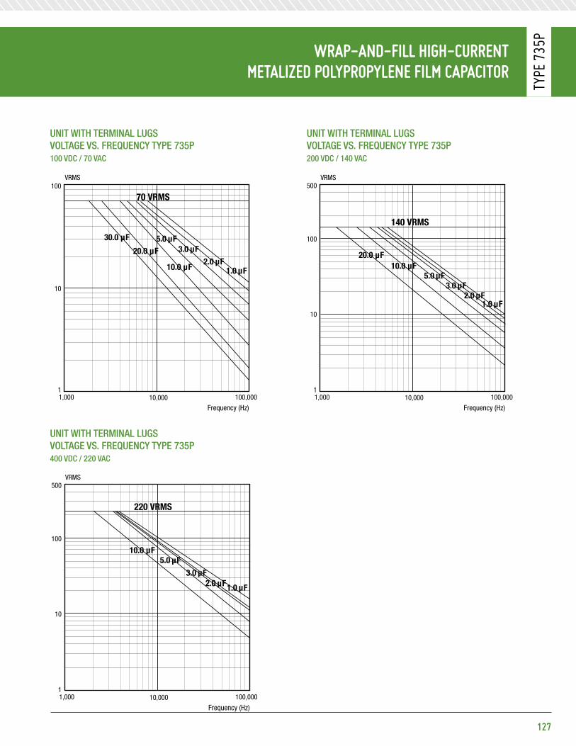
127
Wrap-and-Fill HiGH-CurrentMetalized polypropylene FilM CapaCitor
Type
735
p
unit With teRminal lugsVoltage Vs. FReQuenCY tYpe 735p 100 VDC / 70 VaC
unit With teRminal lugsVoltage Vs. FReQuenCY tYpe 735p 400 VDC / 220 VaC
unit With teRminal lugsVoltage Vs. FReQuenCY tYpe 735p 200 VDC / 140 VaC
3.0 µF5.0 µF
10.0 µF
20.0 µF
70 VRMS
VRMS
10
11,000 10,000 100,000
Frequency (Hz)
VOLTAGE vs FREQUENCY TYPE 735P100VDC\70VAC
2.0 µF1.0 µF
100
30.0 µF
20.0 µF
140 VRMS
VRMS
10
11,000 10,000 100,000
Frequency (Hz)
VOLTAGE vs FREQUENCY TYPE 735P200VDC\140VAC
500
100
3.0 µF5.0 µF
10.0 µF
2.0 µF1.0 µF
3.0 µF5.0 µF
10.0 µF
220 VRMS
VRMS
10
11,000 10,000 100,000
Frequency (Hz)
VOLTAGE vs FREQUENCY TYPE 735P400VDC\220VAC
500
2.0 µF1.0 µF
100
3.0 µF5.0 µF
10.0 µF
20.0 µF
70 VRMS
VRMS
10
11,000 10,000 100,000
Frequency (Hz)
VOLTAGE vs FREQUENCY TYPE 735P100VDC\70VAC
2.0 µF1.0 µF
100
30.0 µF
20.0 µF
140 VRMS
VRMS
10
11,000 10,000 100,000
Frequency (Hz)
VOLTAGE vs FREQUENCY TYPE 735P200VDC\140VAC
500
100
3.0 µF5.0 µF
10.0 µF
2.0 µF1.0 µF
3.0 µF5.0 µF
10.0 µF
220 VRMS
VRMS
10
11,000 10,000 100,000
Frequency (Hz)
VOLTAGE vs FREQUENCY TYPE 735P400VDC\220VAC
500
2.0 µF1.0 µF
1003.0 µF
5.0 µF
10.0 µF
20.0 µF
70 VRMS
VRMS
10
11,000 10,000 100,000
Frequency (Hz)
VOLTAGE vs FREQUENCY TYPE 735P100VDC\70VAC
2.0 µF1.0 µF
100
30.0 µF
20.0 µF
140 VRMS
VRMS
10
11,000 10,000 100,000
Frequency (Hz)
VOLTAGE vs FREQUENCY TYPE 735P200VDC\140VAC
500
100
3.0 µF5.0 µF
10.0 µF
2.0 µF1.0 µF
3.0 µF5.0 µF
10.0 µF
220 VRMS
VRMS
10
11,000 10,000 100,000
Frequency (Hz)
VOLTAGE vs FREQUENCY TYPE 735P400VDC\220VAC
500
2.0 µF1.0 µF
100

preForMed reCtanGular BoXMetalized polypropylene FilM CapaCitors
Type
744
G
eleCtriCal speCiFiCationsCapaCitanCe Range:0.47 μF to 3.5 μF
Voltage Rating:600 VDC
CapaCitanCe toleRanCe:±20%, ±10%, ±5%
opeRating tempeRatuRe:-55°C to +105°C
Voltage DeRating:At +105°C, 70% of the 85°C rating
Dissipation FaCtoR:0.07% maximum
DC Voltage test:150% of rated voltage for 2 minutes
insulation ResistanCe:Measure at rated VDC after a 2 minute charge.
• At +25°C, 100,000 Megaohm-Microfarads, need not exceed 200,000 Megaohms
diMensions (in inches)
128
Features• Flame retardant case • Small size light weight • High insulation resistance • Low ESR
majoR appliCations:Timing, integrating, telecommunications, AC, audio, and digital circuitry.
pHysiCal CHaraCteristiCsConstRuCtion:Non-inductive wound metalized polypropylene.
Case:Flame retardant preformed case and epoxy fill.
leaD mateRial:Solder coated solid wire No. 18 AWG.
leaD stRength:Capable of withstanding a five pound pull force on lead axis.
maRking:Dearborn trademark, type or catalog number, capacitance, tolerance and voltage.
G-ForCePower caPaciTors
LS ±0.031 LD ±0.031
L Max. T Max. T Max.
H Max. H Max.
1.00 Min.
1.00 Min.

standard ratinGsCapacitance
μFVDC t h l ls lD
0.47 600 0.400 0.790 1.015 0.90 -0.68 600 0.400 0.790 1.015 0.90 -1.00 600 0.520 0.790 1.215 1.10 0.302.50 600 0.895 0.790 1.390 1.20 0.503.00 600 0.920 0.790 1.645 1.40 0.503.50 600 0.920 0.790 1.645 1.40 0.50
Additional capacitance values, voltages, and tolerances are available upon request.
129
preForMed reCtanGular BoXMetalized polypropylene FilM CapaCitors
Type
744
G

iGBt snuBBer CapaCitorsMetalized polypropylene FilM dieleCtriC CapaCitors
Type
752
p
eleCtriCal speCiFiCationsCapaCitanCe Range:0.10 μF to 2.5 μF
CapaCitanCe toleRanCe:±20%, ±10%, ±5%
Voltage Range:• 800 VDC to 3,000 VDC • 460 VRMS to 920 VRMS
Voltage DeRating:At +105°C, 70% of the 85°C rating
opeRating tempeRatuRe:• -55°C to +105°C for DC operation • -55°C to +85°C for AC operation
Dissipation FaCtoR:0.10% maximum
eQuiValent seRies inDuCtanCe:< 26nH
eQuiValent seRies ResistanCe:See standard ratings table
DC Voltage test:150% of rated voltage for 2 minutes
insulation ResistanCe:Measure at 500 VDC after a 2 minute charge.
• At +25°C, 175,000 Megaohm-Microfarads, need not exceed 350,000 Megaohms • At +85°C, 10,000 Megaohm-Microfarads, need not exceed 20,000 Megaohms
diMensions (in inches)
130
Features• Low ESL and ESR • Voltage ratings to 3,000 VDC / 920 VRMS • Ripple current greater than 20 ARMS @ 85°C • Across the bus 23 - 28 mm terminal spacing • 105°C operating temperature • dv / dt Capabilities to 3,300 V / μs
majoR appliCations:Snubber, industrial controls, AC drives and inverters, UPS, charging systems, and other high voltage electronic applications.
pHysiCal CHaraCteristiCsConstRuCtion:Non-inductive wound metalized polypropylene.
Case:Flame retardant molded plastic case and epoxy fill.
Dimensions (in inches):Case length Width height
1 1.65 1.25 1.252 1.77 1.46 1.46
teRminals:Tinned copper tabs.
maRking:Dearborn trademark, type or catalog number, capacitance, tolerance and voltage.
G-ForCePower caPaciTors
Consult factory for other terminal configurations and/or spacing.
0.240" x 0.340"Slotted hole
0.550" +/- 0.015"
0.945" +/- 0.047"
LengthSee Table
WidthSee Table
B elytS*A elytS
*Otherwise Style A identical to Style B
0.250 +/- 0.30"
HeightSee Table
0.400" +/- 0.060"
0.055" typical
0.032" Nominal
0.600" =/-0.060"
Consult factory for other terminal configurations and/or spacing.

131
iGBt snuBBer CapaCitorsMetalized polypropylene FilM dieleCtriC CapaCitors
Type
752
p
standard ratinGsCapacitance
Case sizetypical esR mΩ 100khz
max. Ripple Curretn at 100khz (amp)i peak (amp)
dv / dt (V / μs)μF Code 50°C 85°C
800 VDC / 460 VRMS* (Voltage Code 800)0.39 394 1 9.9 16.2 13.0 300 7850.47 474 1 8.4 17.8 14.2 370 7850.56 564 1 8.3 19.4 15.5 380 6750.68 684 1 9.8 21.5 17.2 385 5650.75 754 1 9.0 22.5 18.0 425 5650.82 824 1 8.3 23.6 18.9 460 5651.0 105 1 6.9 26.0 20.8 565 5101.2 125 2 6.7 26.0 20.8 595 4351.4 145 2 5.9 26.0 20.8 695 4251.5 155 2 5.5 26.0 20.8 745 4251.8 185 2 6.5 26.0 20.8 720 4002.0 205 2 6.0 26.0 20.8 800 3452.2 225 2 5.5 26.0 20.8 880 3352.5 255 2 4.9 26.0 20.8 1000 335
1,000 VDC / 460 VRMS* (Voltage Code 1K0)0.33 334 1 9.6 14.9 11.9 269 8950.39 394 1 9.9 16.2 13.0 300 7850.47 474 1 8.4 17.8 14.2 370 7850.56 564 1 8.3 19.4 15.5 380 6750.68 684 1 9.8 21.5 17.2 385 5650.75 754 1 9.0 22.5 18.0 425 5650.82 824 1 8.3 23.6 18.9 460 5651.0 105 1 6.9 26.0 20.8 565 5101.2 125 2 6.7 26.0 20.8 595 4351.4 145 2 5.9 26.0 20.8 695 4251.5 155 2 5.5 26.0 20.8 745 425
1,200 VDC / 460 VRMS* (Voltage Code 1K2)0.27 274 1-2 11.6 13.5 10.8 240 8950.33 334 1-2 9.6 14.9 11.9 269 8950.39 394 1-2 9.9 16.2 13.0 300 7850.47 474 1-2 8.4 17.8 14.2 370 7850.56 564 1-2 8.3 19.4 15.5 380 6750.68 684 1 9.8 21.5 17.2 385 565
0.75 754 1 9.0 22.5 18.0 425 565
0.82 824 1 8.3 23.6 18.9 460 5651.0 105 1 6.9 26.0 20.8 565 5101.2 125 2 6.7 26.0 20.8 595 4351.4 145 2 5.9 26.0 20.8 695 4251.5 155 2 5.5 26.0 20.8 745 425
1,600 VDC / 920 VRMS* (Voltage Code 1K6)0.10 104 1 16.8 8.2 6.6 308 30800.12 124 1 14.1 9.0 7.2 370 29450.15 154 1 9.8 10.1 8.1 460 27900.18 184 1 9.7 11.0 8.8 555 26350.22 224 1 9.4 13.0 10.4 585 23400.27 274 1-2 7.8 14.4 11.5 600 20400.33 334 1-2 8.0 15.9 12.7 660 18450.39 394 1-2 6.9 17.4 13.9 860 17500.47 474 1-2 7.6 19.1 15.2 860 15650.56 564 1-2 6.5 21.9 17.5 1030 1475
Additional capacitance values, voltages, and tolerances are available upon request.
* AC voltage rating is at 400Hz.

iGBt snuBBer CapaCitorsMetalized polypropylene FilM dieleCtriC CapaCitors
Type
752
p
132
standard ratinGsCapacitance
Case sizetypical esR mΩ 100khz
max. Ripple Curretn at 100khz (amp)i peak (amp)
dv / dt (V / μs)μF Code 50°C 85°C
2,000 VDC / 920 VRMS* (Voltage Code 2K0)0.10 104 1 16.8 8.2 6.6 308 30800.12 124 1 14.1 9.0 7.2 370 29450.15 154 1 9.8 10.1 8.1 460 27900.18 184 1 9.7 11.0 8.8 555 26350.22 224 1 9.4 13.0 10.4 585 23400.27 274 2 7.8 14.4 11.5 600 20400.33 334 2 8.2 15.9 12.7 660 18450.39 394 2 6.9 17.4 13.9 860 1750
2,400 VDC / 920 VRMS* (Voltage Code 2K4)0.10 104 1 16.8 8.2 6.6 308 30800.12 124 1 14.1 9.0 7.2 370 29450.15 154 1 9.8 10.1 8.1 460 27900.18 184 1 9.7 11.0 8.8 555 26350.22 224 1 9.4 13.0 10.4 585 23400.27 274 2 7.8 14.4 11.5 600 20400.33 334 2 8.0 15.9 12.7 660 1845
3,000 VDC / 920 VRMS* (Voltage Code 3K0)0.10 104 1 14.1 8.2 6.6 350 33150.12 124 1 11.9 9.0 7.2 420 31600.15 154 2 11.3 11.3 9.0 440 25700.18 184 2 9.5 12.4 9.9 525 24750.22 224 2 7.9 13.7 11.0 640 2385
Additional capacitance values, voltages, and tolerances are available upon request.
* AC voltage rating is at 400Hz.
typiCal iMpedanCe Curve
1,000
100
10
1
0.1
0.01
0.001
10,000
Frequency (Hz)
752P Typical Impedance Curve
100kHz 1kHz 10kHz 100kHz 1MHz 10MHz
Impe
danc
e in
Ohm
s
0.15 µF
0.22 µF
2µF

133
Metalized polypropylene FilMCapaCitor alternative to aluMinuM eleCtrolytiCs
Type
781
p
133
eleCtriCal speCiFiCationsCapaCitanCe toleRanCe:±20%, ±10%
CapaCitanCe Change:±5% from –55°C to +85°C
opeRating tempeRatuRe:-55°C to +85°C
Dissipation FaCtoR:1.0% Maximum at 1kHz
DC Voltage test:140% of rated voltage for 1 minute
insulation ResistanCe:Measure at 500 VDC after a 10 minute charge.
• At +25°C, 20,000 Megaohm-Microfarads • At +85°C, 2,000 Megaohm-Microfarads
CoeFFiCients For ripple Current
temperature25°C 50°C 70°C
1.7x 1.4x 1x
Frequency Voltage Rating
60hz 120hz 400hz 1khz
600, 800, 900 0.17x 0.35x 1x 1.58x
1,000, 1,200 0.14x 0.28x 1x 1.58x
1,300, 1,500 0.11x 0.22x 1x 1.58x
1,800 0.08x 0.16x 1x 1.58x
diMensions (in inches)
Features• Non-polar construction • Voltage ratings to 1,800 VDC • Superior performance from -55°C to +85°C • Greater current density • Higher over voltage protection • Dry construction eliminates electrolyte leakage • Improved reliability • Longer shelf life
majoR appliCations:Filmlytics offer the same package dimensions and terminations as standard electrolytics with all the advantages of self-healing metalized film electrodes and the superior performance of film capacitors.
pHysiCal CHaraCteristiCsConstRuCtion: Dry, non-inductively wound metalized film.
Case: Aluminum case with plastic insulating sleeve.
teRminals: High current terminals mounted on a plastic deck.
maRking: Dearborn trademark, type or catalog number, capacitance, tolerance and voltage.
CapaCitanCe Change Vs. tempeRatuRe
Height
H= 0.25" nominalL= 0.125" nominal
3.00" nominal
1.25" nominal0.344" Deep Min.1/4-28
0.68" nominal
0
5
-10
-15
-20
-5
Temperature (°C)
-75 -50 -25 0 25 50 75 100
Capacitance Change vs Temperature
Filmlytic
Aluminum Electrolytic
Capa
cita
nce
Chan
ge (%
)

Metalized polypropylene FilMCapaCitor alternative to aluMinuM eleCtrolytiCs
Type
781
p
134
standard ratinGsCapacitance
Case sizetypical esR mΩ 100khz
dv / dt (V / μs)
max. i. rms @70°C, 400hzμF Code
600 VDC (Voltage Code 600)200 207 3.2 6.3 8.3 38.8300 307 4.2 9.1 5.3 53.6400 407 5.2 11.8 3.9 68.3
800 VDC (Voltage Code 800)120 127 3.2 8.0 10.3 29.4190 197 4.2 11.1 6.6 42.5260 267 5.2 13.9 4.8 56.1
900 VDC (Voltage Code 900)85 856 3.2 8.8 12.8 25.2
130 137 4.2 12.4 8.1 36.3180 187 5.2 16.5 5.9 46.2
1,000 VDC (Voltage Code 1K0)60 606 3.2 10.4 15.0 20.995 95 4.2 14.9 9.5 30.0130 137 5.2 19.3 6.9 39.0
1,200 VDC (Voltage Code 1K2)45 456 3.2 11.1 18.5 18.570 706 4.2 16.6 11.3 25.9100 107 5.2 21.1 8.2 34.6
1,300 VDC (Voltage Code 1K3)35 356 3.2 12.5 20.7 16.255 556 4.2 18.6 12.7 22.975 756 5.2 24.7 9.2 29.5
1,500 VDC (Voltage Code 1K5)28 286 3.2 13.9 23.1 14.445 456 4.2 20.3 14.2 20.865 656 5.2 25.6 10.2 28.1
1,800 VDC (Voltage Code 1K8)18 186 3.2 16.3 30.1 11.630 306 4.2 23.9 17.9 17.042 426 5.2 31.5 12.7 22.3
Additional capacitance values, voltages, and tolerances are available upon request.

Wrap-and-Fill HiGH FreQuenCy polypropylene FilM / Foil CapaCitors
Type
710
p
135
eleCtriCal speCiFiCationsCapaCitanCe Range: 0.001 μF to 1.0 μF
Voltage Rating:• 200 VDC to 800 VDC • 155 VRMS to 500 VRMS
CapaCitanCe toleRanCe: ±20%, ±10%, ±5%
opeRating tempeRatuRe: -55°C to +105°C
Voltage DeRating:• At +105°C, 70% of the 85° rating for DC applications. • For AC applications above 85°C, see Table 1.
Dissipation FaCtoR: 0.1% maximum
DC Voltage test: 250% of rated voltage for 5 seconds
insulation ResistanCe:Measured at rated VDC after a 2 minute test.
• At +25°C, 200,000 Megaohm-Microfarads, need not exceed 400,000 Megaohms • At +85°C, 10,000 Megaohm-Microfarads, need not exceed 20,000 Megaohms • At +105°C, 1,000 Megaohm-Microfarads, need not exceed 2,000 Megaohms
MaXiMuM pulse rise tiMeCapacitor
length (inch)
Rise time dv / dt (v / μs)
200 VDC 400 VDC 600 VDC 800 VDC
0.750 1000 1800 3000 -
0.938 700 1000 2000 -
1.250 450 650 1000 1500
1.688 400 500 700 1000
2.063 300 - 600 800
2.438 - 400 500 600
diMensions (in inches)
Features• Extended foil construction• Low-loss• High average AC current• Moisture resistant • Approved to MIL-PRF-55514 / 10
majoR appliCations:High current and high pulse operations, protection circuits in SMPS, snubber and SCR commutating circuits, oscillator, timing and filter circuits, high frequency coupling.
pHysiCal CHaraCteristiCsConstRuCtion:Polypropylene film extended aluminum foil.
Case:Flame retardant polyester tape wrap and epoxy endfill.
leaD mateRial:Solder coated solid wire.
leaD stRength:Capable of withstanding a five pound pull force on lead axis.
maRking:Dearborn trademark, type or catalog number, capacitance, tolerance and voltage.
* Leads to be within ±0.062” of center line at egress, but not less than 0.031” from edge.
0.032 nominalDia. (No. 20 AWG)
DMax.
1.750Min.
1.750Min.
Max.L
Solid tinned wire*
± 0.062

Wrap-and-Fill HiGH FreQuenCy polypropylene FilM / Foil CapaCitors
Type
710
p
taBle 1: aC voltaGe ratinGsCapacitance
Range1,000hz 5,000hz 10,000hz 15,000hz 20,000hz - Voltage Rms max. aC
life test85°C 105°C 85°C 105°C 85°C 105°C 85°C 105°C 85°C 105°C200 V
0.012 - 0.068 155 75 115 75 85 60 70 50 60 45 1550.082 - 0.47 155 75 75 60 55 40 45 35 40 30 1550.68 - 1.0 155 75 75 50 55 30 45 20 40 15 155
400 V0.0039 - 0.033 200 100 190 100 135 105 110 85 95 75 2000.039 - 0.47 200 100 100 80 75 55 60 45 50 40 200
0.68- 1.0 200 100 100 50 75 30 60 20 50 15 200600 V
0.001 - 0.033 200 140 200 165 160 120 130 100 110 85 2000.039 - 0.22 200 140 125 95 90 65 75 55 65 45 2000.27 - 1.0 200 100 125 55 90 30 75 20 60 15 200
800 V0.0056 - 0.033 500 250 500 190 500 150 450 120 405 100 5000.039 - 0.10 500 250 400 120 240 100 185 75 140 60 5000.12 - 0.56 500 195 280 75 160 45 115 30 85 20 500
standard ratinGs
CapacitanceVoltage Code 200
200 VDC / 155 VaC*Voltage Code 400
400 VDC / 200 VaC*Voltage Code 600
600 VDC / 240 VaC*Voltage Code 800
800 VDC / 500 VaC*μF Code D l D l D l D l
0.0010 102 - - - - 0.290 0.750 - -0.0012 122 - - - - 0.305 0.750 - -0.0015 152 - - - - 0.305 0.750 - -0.0018 182 - - - - 0.315 0.750 - -0.0022 222 - - - - 0.315 0.750 - -0.0027 272 - - - - 0.320 0.750 - -0.0033 332 - - 0.320 0.750 - -0.0039 392 - - 0.240 0.750 0.330 0.750 - -0.0047 472 - - 0.240 0.750 0.330 0.750 - -0.0056 562 - - 0.270 0.750 0.360 0.750 0.275 1.2500.0068 682 - - 0.270 0.750 0.360 0.750 0.275 1.2500.0082 822 - - 0.290 0.750 0.340 0.938 0.315 1.2500.010 103 - - 0.290 0.750 0.340 0.938 0.315 1.2500.012 123 0.250 0.750 0.330 0.750 0.390 0.938 0.365 1.2500.015 153 0.250 0.750 0.330 0.750 0.390 0.938 0.365 1.2500.018 183 0.290 0.750 0.325 0.938 0.450 0.938 0.430 1.2500.022 223 0.290 0.750 0.325 0.938 0.450 0.938 0.430 1.2500.027 273 0.335 0.750 0.375 0.938 0.435 1.250 0.515 1.2500.033 333 0.335 0.750 0.375 0.938 0.435 1.250 0.515 1.2500.039 393 0.315 0.938 0.355 1.250 0.490 1.250 0.495 1.6880.047 473 0.315 0.938 0.355 1.250 0.490 1.250 0.495 1.6880.056 563 0.375 0.938 0.415 1.250 0.590 1.250 0.595 1.6880.068 683 0.375 0.938 0.415 1.250 0.590 1.250 0.595 1.6880.082 823 0.360 1.250 0.485 1.250 0.690 1.250 0.700 1.6880.10 104 0.360 1.250 0.485 1.250 0.690 1..250 0.700 1.6880.12 124 0.420 1.250 0.570 1.250 0.670 1.688 0.755 2.0630.15 154 0.420 1.250 0.570 1.250 0.670 1.688 0.755 2.0630.18 184 0.495 1.250 0.595 1.688 0.800 1.688 0.910 2.0630.22 224 0.495 1.250 0.595 1.688 0.800 1.688 0.910 2.0630.33 334 0.510 1.688 0.690 1.688 0.876 2.063 0.985 2.4380.39 394 0.510 1.688 0.690 1.688 1.032 2.063 0.985 2.4380.47 474 0.590 1.688 0.830 1.688 1.032 2.063 1.220 2.4380.56 564 0.590 1.688 0.830 1.688 1.096 2.438 1.220 2.4380.68 684 0.799 1.688 0.911 2.438 1.096 2.438 1.220 2.4380.82 824 0.821 2.063 1.091 2.438 1.316 2.438 - -1.00 105 0.821 2.063 1.091 2.438 1.316 2.438 - -
Additional capacitance values, voltages, and tolerances are available upon request. * AC voltage rating is at 400Hz 1.4 x VRMS + VDC should not exceed the rated VDC.
136

Wrap-and-Fill Metalized polypHenylenesulFide FilM CapaCitors
Type
832
p
137
eleCtriCal speCiFiCationsCapaCitanCe Range: 0.001 μF to 10.0 μF
Voltage Rating: • 63 VDC to 400 VDC • 40 VRMS to 200 VRMS
CapaCitanCe toleRanCe: ±10%, ±5%, ±2%
opeRating tempeRatuRe: -55°C to +125°C without derating for DC operation
aC opeRation: Limited to +105°C
Dissipation FaCtoR: 0.15% maximum when measured at 1kHz @ 25°C
DC Voltage test: 200% of rated voltage for 1 minute
insulation ResistanCe:Measure at rated VDC after a 2 minute charge.
• At + 25°C, 50,000 Megaohm-Microfarads, need not exceed 100,000 Megaohms• At + 85°C, 2,000 Megaohm-Microfarads, need not exceed 4,000 Megaohms• At + 125°C, 250 Megaohm-Microfarads, need not exceed 500 Megaohms
MaXiMuM pulse rise tiMeCapacitor
length (inch)
Rise time dv / dt (V / μs)
63 V 100 V 250 V 400 V
0.440 25 35 57 100
0.560 17 23 38 65
0.750 9 14 20 35
1.000 6 9 14 20
1.250 5 7 11 17
1.310 4 6 - 16
1.500 - 5 - -
1.560 - - 6 -
1.810 - - 5 10
2.060 - - 4 -
2.310 - - - 7
diMensions (in inches)
Features• High temperature to 125°C• Superior performance• High efficiency• High stability• High reliability• Rugged construction• Small size
majoR appliCations:Filtering, timing, storage, and integrating circuits.
pHysiCal CHaraCteristiCsConstRuCtion:Non-inductive wound metalized polyphenylene sulfide.
Case: Flame retardant tape wrap and epoxy endfill.
leaD mateRial: Solder coated solid wire.
leaD WiRe sizes:
Case Dia. lead aWg
< 0.230 0.020 (No. 24)
< 0.350 0.025 (No. 22)
≥ 0.350 0.032 (No. 20)
leaD stRength:Capable of withstanding a five pound pull force on lead axis.
maRking:Dearborn trademark, type or catalog number, capacitance, tolerance and voltage.
DMax.
1.625Min.
1.625Min.
Max.L
Solid tinned wire*
* Leads to be within ±0.062” of center line at egress, but not less than 0.031” from edge.
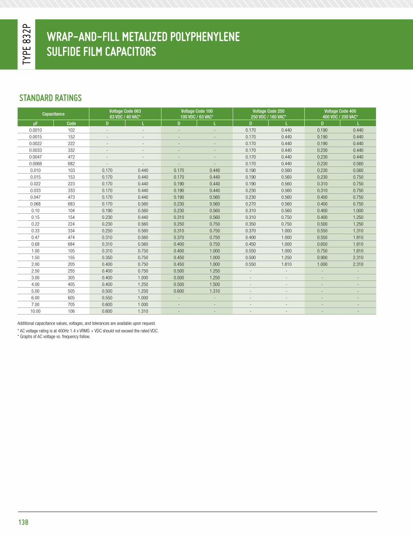
Wrap-and-Fill Metalized polypHenylenesulFide FilM CapaCitors
Type
832
p
standard ratinGs
CapacitanceVoltage Code 063 63 VDC / 40 VaC*
Voltage Code 100100 VDC / 63 VaC*
Voltage Code 250250 VDC / 160 VaC*
Voltage Code 400400 VDC / 200 VaC*
μF Code D l D l D l D l0.0010 102 - - - - 0.170 0.440 0.190 0.4400.0015 152 - - - - 0.170 0.440 0.190 0.4400.0022 222 - - - - 0.170 0.440 0.190 0.4400.0033 332 - - - - 0.170 0.440 0.230 0.4400.0047 472 - - - - 0.170 0.440 0.230 0.4400.0068 682 - - - - 0.170 0.440 0.230 0.5600.010 103 0.170 0.440 0.170 0.440 0.190 0.560 0.230 0.5600.015 153 0.170 0.440 0.170 0.440 0.190 0.560 0.230 0.7500.022 223 0.170 0.440 0.190 0.440 0.190 0.560 0.310 0.7500.033 333 0.170 0.440 0.190 0.440 0.230 0.560 0.310 0.7500.047 473 0.170 0.440 0.190 0.560 0.230 0.560 0.400 0.7500.068 683 0.170 0.560 0.230 0.560 0.270 0.560 0.400 0.7500.10 104 0.190 0.560 0.230 0.560 0.310 0.560 0.400 1.0000.15 154 0.230 0.440 0.310 0.560 0.310 0.750 0.400 1.2500.22 224 0.230 0.560 0.250 0.750 0.350 0.750 0.500 1.2500.33 334 0.250 0.560 0.310 0.750 0.370 1.000 0.550 1.3100.47 474 0.310 0.560 0.370 0.750 0.400 1.000 0.550 1.8100.68 684 0.310 0.560 0.400 0.750 0.450 1.000 0.650 1.8101.00 105 0.310 0.750 0.400 1.000 0.550 1.000 0.750 1.8101.50 155 0.350 0.750 0.450 1.000 0.500 1.250 0.900 2.3102.00 205 0.400 0.750 0.450 1.000 0.550 1.810 1.000 2.3102.50 255 0.400 0.750 0.500 1.250 - - - -3.00 305 0.400 1.000 0.500 1.250 - - - -4.00 405 0.400 1.250 0.500 1.500 - - - -5.00 505 0.500 1.250 0.600 1.310 - - - -6.00 605 0.550 1.000 - - - - - -7.00 705 0.600 1.000 - - - - - -
10.00 106 0.600 1.310 - - - - - -
Additional capacitance values, voltages, and tolerances are available upon request.
* AC voltage rating is at 400Hz 1.4 x VRMS + VDC should not exceed the rated VDC.* Graphs of AC voltage vs. frequency follow.
138

139
Wrap-and-Fill Metalized polypHenylenesulFide FilM CapaCitors
Type
832
p
Voltage Vs. FReQuenCY tYpe 832p 63 VDC / 40 VaC
Voltage Vs. FReQuenCY tYpe 832p 250 VDC / 160 VaC
Voltage Vs. FReQuenCY tYpe 832p 100 VDC / 63 VaC
Voltage Vs. FReQuenCY tYpe 832p 400 VDC / 200 VaC
40 VRMS
VRMS
10
11,000 10,000 100,000
VOLTAGE vs FREQUENCY TYPE 832P63VDC\40VAC
100
0.047 µF
1.0 µF
10.0 µF5.0 µF
0.33µF
0.022 µF
2.5 µF
63 VRMS
VRMS
10
11,000 10,000 100,000
VOLTAGE vs FREQUENCY TYPE 832P100VDC\63VAC
100
0.047µF
1.0 µF5.0 µF
2.5 µF
0.1 µF0.022 µF
0.33 µF
160 VRMS
VRMS
10
11,000 10,000 100,000
VOLTAGE vs FREQUENCY TYPE 832P250VDC\160VAC
300
100
0.10 µF0.47µF
2.0 µF
0.047µF 0.01µF
200 VRMS
VRMS
10
11,000 10,000 100,000
VOLTAGE vs FREQUENCY TYPE 832P400VDC\200VAC
300
100
0.047µF
0.47µF2.0 µF 0.0047µF
0.01µF
0.1µF
Frequency (Hz) Frequency (Hz)
Frequency (Hz) Frequency (Hz)
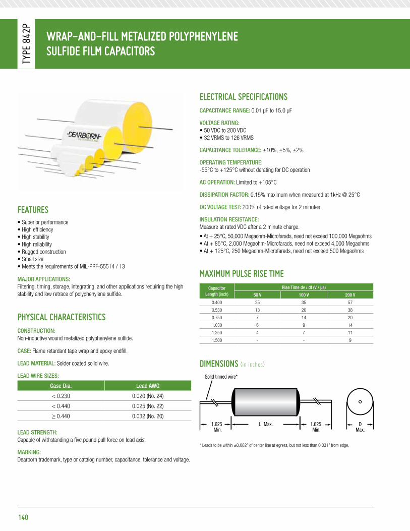
Wrap-and-Fill Metalized polypHenylenesulFide FilM CapaCitors
Type
842
p
140
eleCtriCal speCiFiCationsCapaCitanCe Range: 0.01 μF to 15.0 μF
Voltage Rating: • 50 VDC to 200 VDC • 32 VRMS to 126 VRMS
CapaCitanCe toleRanCe: ±10%, ±5%, ±2%
opeRating tempeRatuRe: -55°C to +125°C without derating for DC operation
aC opeRation: Limited to +105°C
Dissipation FaCtoR: 0.15% maximum when measured at 1kHz @ 25°C
DC Voltage test: 200% of rated voltage for 2 minutes
insulation ResistanCe:Measure at rated VDC after a 2 minute charge.
• At + 25°C, 50,000 Megaohm-Microfarads, need not exceed 100,000 Megaohms• At + 85°C, 2,000 Megaohm-Microfarads, need not exceed 4,000 Megaohms• At + 125°C, 250 Megaohm-Microfarads, need not exceed 500 Megaohms
MaXiMuM pulse rise tiMeCapacitor
length (inch)
Rise time dv / dt (V / μs)
50 V 100 V 200 V
0.400 25 35 57
0.530 13 20 38
0.750 7 14 20
1.030 6 9 14
1.250 4 7 11
1.500 - - 9
diMensions (in inches)
Features• Superior performance• High efficiency• High stability• High reliability• Rugged construction• Small size• Meets the requirements of MIL-PRF-55514 / 13
majoR appliCations:Filtering, timing, storage, integrating, and other applications requiring the high stability and low retrace of polyphenylene sulfide.
pHysiCal CHaraCteristiCsConstRuCtion:Non-inductive wound metalized polyphenylene sulfide.
Case: Flame retardant tape wrap and epoxy endfill.
leaD mateRial: Solder coated solid wire.
leaD WiRe sizes:
Case Dia. lead aWg
< 0.230 0.020 (No. 24)
< 0.440 0.025 (No. 22)
≥ 0.440 0.032 (No. 20)
leaD stRength:Capable of withstanding a five pound pull force on lead axis.
maRking:Dearborn trademark, type or catalog number, capacitance, tolerance and voltage.
DMax.
1.625Min.
1.625Min.
Max.L
Solid tinned wire*
* Leads to be within ±0.062” of center line at egress, but not less than 0.031” from edge.

Wrap-and-Fill Metalized polypHenylenesulFide FilM CapaCitors
Type
842
p
141
standard ratinGs
CapacitanceVoltage Code 050 50 VDC / 32 VaC*
Voltage Code 100100 VDC / 63 VaC*
Voltage Code 200200 VDC / 126 VaC*
μF Code D l D l D l0.010 103 0.17 0.40 0.17 0.40 0.17 0.400.015 153 0.17 0.40 0.17 0.40 0.19 0.400.022 223 0.17 0.40 0.17 0.40 0.23 0.400.033 333 0.17 0.40 0.19 0.40 0.26 0.400.047 473 0.17 0.40 0.23 0.40 0.23 0.530.068 683 0.17 0.40 0.26 0.40 0.26 0.530.10 104 0.23 0.40 0.23 0.53 0.31 0.530.15 154 0.23 0.40 0.26 0.53 0.31 0.750.22 224 0.26 0.40 0.31 0.53 0.35 0.750.33 334 0.26 0.53 0.35 0.53 0.40 0.750.47 474 0.31 0.53 0.31 0.75 0.40 1.030.68 684 0.35 0.53 0.35 0.75 0.44 1.031.00 105 0.31 0.75 0.40 0.75 0.49 1.251.50 155 0.35 0.75 0.40 1.03 0.56 1.252.00 205 0.40 0.75 0.44 1.03 0.56 1.502.70 275 0.35 1.03 0.51 1.03 0.67 1.503.00 305 0.40 1.03 0.49 1.25 0.67 1.503.90 395 0.44 1.03 0.56 1.25 0.76 1.505.00 505 0.49 1.03 0.61 1.25 0.87 2.065.60 565 0.49 1.03 0.56 1.50 - -6.80 685 0.49 1.25 0.61 1.50 - -10.00 106 0.61 1.25 - - - -15.00 156 0.61 1.50 - - - -
Additional capacitance values, voltages, and tolerances are available upon request.
* AC voltage rating is at 400Hz 1.4 x VRMS + VDC should not exceed the rated VDC.* Graphs of AC voltage vs. frequency follow.

Wrap-and-Fill Metalized polypHenylenesulFide FilM CapaCitors
Type
842
p
Voltage Vs. FReQuenCY tYpe 842p 50 VDC / 32 VaC
Voltage Vs. FReQuenCY tYpe 842p 200 VDC / 126 VaC
Voltage Vs. FReQuenCY tYpe 842p 100 VDC / 63 VaC
32 VRMS
VRMS
10
11,000 10,000 100,000
Frequency (Hz)
VOLTAGE vs FREQUENCY TYPE 842P50VDC\32VAC
50
0.068 µF
1.0 µF6.8 µF
15 µF
0.15µF
0.01µF
0.47µF
63 VRMS
VRMS
10
11,000 10,000 100,000
Frequency (Hz)
VOLTAGE vs FREQUENCY TYPE 842P100VDC\63VAC
100
0.068 µF
1.0 µF
6.8 µF3.0 µF
0.15 µF0.01 µF
0.47 µF
126 VRMS
VRMS
10
11,000 10,000 100,000
Frequency (Hz)
VOLTAGE vs FREQUENCY TYPE 842P200VDC\126VAC
300
100
0.068 µF
1.0 µF0.47µF
3.0 µF
0.15µF
0.01µF
142

143
Wrap-and-Fill Metalized polypHenylenesulFide FilM CapaCitors
Type
880
p
eleCtriCal speCiFiCationsCapaCitanCe Range: 0.0047 μF to 10.0 μF
Voltage Rating: • 50 VDC to 400 VDC • 32 VRMS to 240 VRMS
CapaCitanCe toleRanCe: ± 10%, ± 5%, ± 2%
opeRating tempeRatuRe: -55°C to +150°C without derating for DC operation AC operation limited to +125°C
Dissipation FaCtoR: 0.15% max. when measured at 1kHz @ 25°C
DC Voltage test: 200% of rated voltage for 1 min.
insulation ResistanCe:Measured at rated VDC after a 2 minute charge.
• At +25°C, 100,000 Megaohm-Microfarads, need not exceed 200,000 Megaohms• At +85°C, 2,000 Megaohm-Microfarads, need not exceed 4,000 Megaohms• At +125°C, 250 Megaohm-Microfarads, need not exceed 500 Megaohms• At +150°C, 10 Megaohm-Microfarads, need not exceed 100 Megaohms
MaXiMuM pulse rise tiMeCapacitor
length (inch)
Rise time dv / dt (V / μs)
50 V 100 V 200 V 400 V
0.400 25 35 57 100
0.530 13 20 38 65
0.750 7 14 20 35
1.030 6 9 14 20
1.250 4 7 11 17
1.500 - - 9 15
1.750 - - - 10
diMensions (in inches)
Features• High temperature to +150°C• Close tolerances• Rugged / lightweight• Extensive standard ratings
majoR appliCations:Timing, feedback circuits, filtering, decoupling.
pHysiCal CHaraCteristiCsConstRuCtion:Non-inductive wound metalized polyphenylene sulfide.
Case: Flame retardant tape wrap and epoxy endfill.
leaD mateRial: Solder coated solid wire.
leaD WiRe sizes:
Case Dia. lead aWg
< 0.200 0.020 (No. 24)
0.200 - 0.300 0.025 (No. 22)
0.301 - 0.500 0.032 (No. 20)
> 0.500 0.040 (No. 18)
leaD stRength:Capable of withstanding a five pound pull force on lead axis.
maRking:Dearborn trademark, type or catalog number, capacitance, tolerance and voltage.
DMax.
1.625Min.
1.625Min.
Max.L
Solid tinned wire*
* Leads to be within ±0.062” of center line at egress, but not less than 0.031” from edge.

Wrap-and-Fill Metalized polypHenylenesulFide FilM CapaCitors
Type
880
p
144
standard ratinGs
CapacitanceVoltage Code 050 50 VDC / 32 VaC*
Voltage Code 100100 VDC / 63 VaC*
Voltage Code 200200 VDC / 126 VaC*
Voltage Code 400400 VDC / 240 VaC*
μF Code D l D l D l D l0.0047 472 - - - - 0.170 0.400 - -0.0068 682 - - - - 0.170 0.400 - -0.010 103 0.170 0.400 0.170 0.400 0.170 0.400 0.260 0.4000.015 153 0.170 0.400 0.170 0.400 0.190 0.400 0.260 0.5300.022 223 0.170 0.400 0.170 0.400 0.230 0.400 0.310 0.5300.033 333 0.170 0.400 0.190 0.400 0.230 0.400 0.390 0.5300.047 473 0.170 0.400 0.230 0.400 0.260 0.400 0.350 0t.7500.068 683 0.170 0.400 0.230 0.400 0.260 0.530 0.400 1.0300.10 104 0.190 0.400 0.260 0.400 0.350 0.530 0.400 1.0300.15 154 0.230 0.400 0.260 0.400 0.310 0.750 0.490 1.0300.22 224 0.260 0.400 0.260 0.530 0.350 0.750 0.490 1.2500.33 334 0.260 0.530 0.350 0.530 0.350 1.030 0.490 1.5000.47 474 0.310 0.530 0.310 0.750 0.400 1.030 0.610 1.5000.68 684 0.310 0.530 0.350 0.750 0.490 1.030 0.670 1.7501.00 105 0.310 0.750 0.440 0.750 0.490 1.250 0.740 1.7501.50 155 0.350 0.750 0.440 1.030 0.560 1.250 - -2.00 205 0.400 0.750 0.490 1.030 0.560 1.500 - -2.70 275 0.350 1.030 0.560 1.030 0.670 1.500 - -3.00 305 0.350 1.030 0.490 1.250 0.670 1.500 - -4.00 405 0.440 1.030 0.610 1.250 - - - -5.00 505 0.490 1.030 0.610 1.250 - - - -6.80 685 0.490 1.250 - - - - - -8.00 805 0.560 1.250 - - - - - -
10.00 106 0.610 1.250 - - - - - -
Additional capacitance values, voltages, and tolerances are available upon request.
* AC voltage rating is at 400Hz 1.4 x VRMS + VDC should not exceed the rated VDC.
typiCal CHaraCteristiCspps FilM / Foil types
1.0
0.5
0.0
-0.5
-1.0
-1.5-55 -25 0 +25 +50 +75 +100 +125
Temperature (°C)
Temperature (°C)
% C
apac
itanc
e Ch
ange
Typical
1.00
0.75
0.50
0.25
0-55 -25 0 +25 +50 +75 +100 +125
% D
issi
patio
n Fa
ctor
IR (M
egaO
hms)
Typical at 1khz
Typical characteristicsPps film/foil types
10,000,000
1,000,000
100,000
10,000
1,000
10025 50 75 100 125 150
Temperature (°C)
Ir vs temperature
ir vs. teMperature
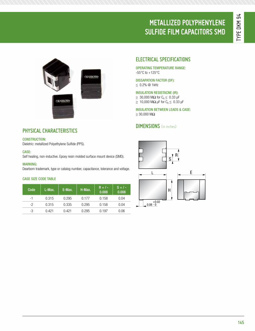
145
Metallized polypHenylene sulFide FilM CapaCitors sMd
Type
DKM
94
eleCtriCal speCiFiCationsopeRating tempeRatuRe Range: -55°C to +125°C
Dissapation FaCtoR (DF): ≤ 0.2% @ 1kHz
insulation ResistaCne (iR):≥ 30,000 MΩ for CR ≤ 0.33 μF≥ 10,000 MΩ.μF for CR ≤ 0.33 μF
insulation betWeen leaDs & Case: ≥ 30,000 MΩ
diMensions (in inches)pHysiCal CHaraCteristiCsConstRuCtion:Dieletric: metallized Polyethylene Sulfide (PPS).
Case: Self healing, non-inductive. Epoxy resin molded surface mount device (SMD).
maRking:Dearborn trademark, type or catalog number, capacitance, tolerance and voltage.
Case size CoDe table
Code l-max. e-max. h-max.R + / - 0.008
s + / - 0.008
-1 0.315 0.295 0.177 0.158 0.04
-2 0.315 0.335 0.295 0.158 0.04
-3 0.421 0.421 0.295 0.197 0.06
L
H
RS
0.08+0.02- 0
E

Metallized polypHenylene sulFide FilM CapaCitors sMd
Type
DKM
94
standard ratinGs
type Dkm 94Capacitance
μF Code 40 VDC 50 VDC 100 VDC0.0047 472 -1 -1 -10.0068 682 -1 -1 -10.0082 822 -1 -1 -10.01 103 -1 -1 -1
0.012 123 -1 -1 -10.015 153 -1 -1 -10.018 183 -1 -1 -10.02 203 -1 -1 -1
0.022 223 -1 -1 -10.033 333 -1 -1 -10.039 393 -1 -1 -10.047 473 -1 -1 -10.068 683 -1 -1 -10.082 823 -1 -1 -10.1 104 -1 -1 -1
0.15 154 -1 -1 -20.22 224 -1 -1 -20.33 334 -2 -2 -30.47 474 -2 -2 -30.5 504 - - -
0.56 564 - - -0.68 684 -3 -3 -
1 105 -3 -3 -1.2 125 -3 - -
orderinG eXaMple:*Dkm94-1333X9050
Tolerances available: +/-20%=X0 +/-10%=X9 +/-5%=X5 +/-2%=X2 +/-1%=X1
146

Wrap and Fill sMall sizepolypHenylene sulFide dieleCtriC FilM / Foil ConstruCtion
Type
810
p
eleCtriCal speCiFiCationsCapaCitanCe Range: 0.001 μF to 1.0 μF
DC Voltage Rating: 50 VDC to 400 VDC
CapaCitanCe toleRanCe: ±20%, ±10%, ±5%
opeRating tempeRatuRe: -55°C to +125°C
Voltage DeRating: At +125°C, 50% of the +85°C rating
Dissipation FaCtoR: 0.15% maximum when measured at 1kHz @ 25°C
Voltage test: 200% of rated voltage for 1 minute
insulation ResistanCe:Measured at rated VDC after a 2 minute charge.
• At +25°C, 50,000 Megaohm-Microfarads, need not exceed 100,000 Megaohms• At +85°C, 2,000 Megaohm-Microfarads, need not exceed 4,000 Megaohms• At +125°C, 250 Megaohm-Microfarads, need not exceed 500 Megaohms
MaXiMuM pulse rise tiMeCapacitor
length (inch)
Rise time dv / dt (V / μs)
50 V 100 V 200 V 400 V
0.560 3200 3700 4400 6000
0.625 1300 - - 3617
0.750 630 1200 1727 2900
1.000 - 680 1147 1636
1.062 470 - 1100 1500
1.250 440 - - 1100
1.312 - 727 - 1000
1.562 - 433 - 900
1.812 270 368 578 -
2.062 - - 442 612
2.312 - 300 - -
2.562 - - - 491
diMensions (in inches)
Features• Extended foil construction• + 125°C rated• Replacement for 610P polycarbonate capacitors• Moisture resistant• Low dissipation factor
majoR appliCations:Oscillator, timing, coupling and decoupling at high frequency, filter circuits.
pHysiCal CHaraCteristiCsConstRuCtion:Non-inductive wound polyphenylene sulfide film and extended foil.
Case: Flame retardant tape wrap and epoxy endfill.
leaD mateRial: Solder coated solid wire.
leaD WiRe sizes:
Case Dia. lead aWg
≤ 0.327 0.025 (No. 22)
> 0.327 0.032 (No. 20)
leaD stRength:Capable of withstanding a five pound pull force on lead axis.
maRking:Dearborn trademark, type or catalog number, capacitance, tolerance and voltage.
DMax.
1.750Min.
1.750Min.
Max.L
Solid tinned wire*
* Leads to be within ±0.062” of center line at egress, but not less than 0.031” from edge.
147
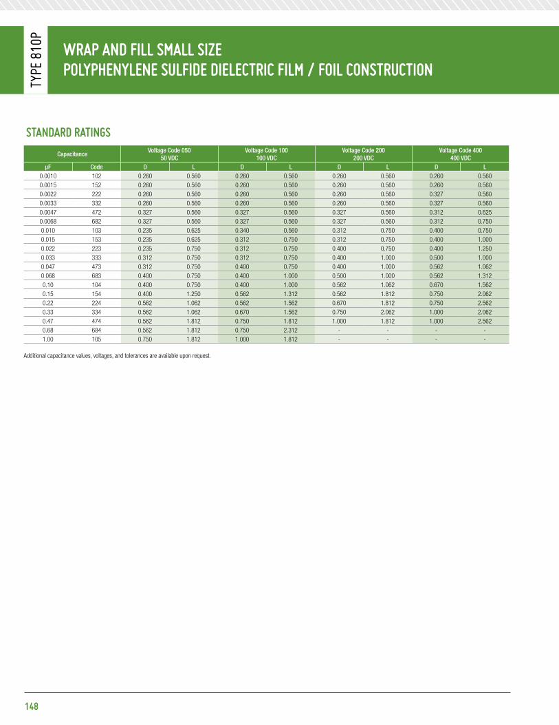
Wrap and Fill sMall sizepolypHenylene sulFide dieleCtriC FilM / Foil ConstruCtion
Type
810
p
standard ratinGs
CapacitanceVoltage Code 050
50 VDCVoltage Code 100
100 VDCVoltage Code 200
200 VDCVoltage Code 400
400 VDCμF Code D l D l D l D l
0.0010 102 0.260 0.560 0.260 0.560 0.260 0.560 0.260 0.5600.0015 152 0.260 0.560 0.260 0.560 0.260 0.560 0.260 0.5600.0022 222 0.260 0.560 0.260 0.560 0.260 0.560 0.327 0.5600.0033 332 0.260 0.560 0.260 0.560 0.260 0.560 0.327 0.5600.0047 472 0.327 0.560 0.327 0.560 0.327 0.560 0.312 0.6250.0068 682 0.327 0.560 0.327 0.560 0.327 0.560 0.312 0.7500.010 103 0.235 0.625 0.340 0.560 0.312 0.750 0.400 0.7500.015 153 0.235 0.625 0.312 0.750 0.312 0.750 0.400 1.0000.022 223 0.235 0.750 0.312 0.750 0.400 0.750 0.400 1.2500.033 333 0.312 0.750 0.312 0.750 0.400 1.000 0.500 1.0000.047 473 0.312 0.750 0.400 0.750 0.400 1.000 0.562 1.0620.068 683 0.400 0.750 0.400 1.000 0.500 1.000 0.562 1.3120.10 104 0.400 0.750 0.400 1.000 0.562 1.062 0.670 1.5620.15 154 0.400 1.250 0.562 1.312 0.562 1.812 0.750 2.0620.22 224 0.562 1.062 0.562 1.562 0.670 1.812 0.750 2.5620.33 334 0.562 1.062 0.670 1.562 0.750 2.062 1.000 2.0620.47 474 0.562 1.812 0.750 1.812 1.000 1.812 1.000 2.5620.68 684 0.562 1.812 0.750 2.312 - - - -1.00 105 0.750 1.812 1.000 1.812 - - - -
Additional capacitance values, voltages, and tolerances are available upon request.
148

149
Wrap-and-Fill zero tCCpolypHenylene sulFide FilM / Foil CapaCitors
Type
882
p
eleCtriCal speCiFiCationsCapaCitanCe Range: 0.001 μF to 0.22 μF
Voltage Rating: 200 VDC
CapaCitanCe toleRanCe: ±10%, ±5%, ±2%
opeRating tempeRatuRe: -55°C to +125°C, without derating
Dissipation FaCtoR: 0.15% maximum
DC Voltage test: 250% of rated voltage for 15 seconds
insulation ResistanCe:Measured at rated VDC after a 2 minute charge.
• At +25°C, 100,000 Megaohm-Microfarads, need not exceed 200,000 Megaohms
diMensions (in inches)
Features• High current Capacity• Close tolerances• Low losses
majoR appliCations:Critical timing, sample and hold, high stability.
pHysiCal CHaraCteristiCsConstRuCtion:Non-inductive wound polyphenylene sulfide film and extended foil.
Case: Flame retardant tape wrap and epoxy endfill.
leaD mateRial: Solder coated solid wire.
leaD WiRe sizes:
Case Dia. lead aWg
< 0.270 0.025 (No. 22)
≥ 0.270 0.032 (No. 20)
leaD stRength:Capable of withstanding a five pound pull force on lead axis.
maRking:Dearborn trademark, type or catalog number, capacitance, tolerance and voltage.
DMax.
1.5Min.
1.5Min.
± 0.062L
Solid tinned wire*

Wrap-and-Fill zero tCCpolypHenylene sulFide FilM / Foil CapaCitors
Type
882
p
standard ratinGs
CapacitanceVoltage Code 200
200 VDCμF Code D l
0.0010 102 0.210 0.4380.0015 152 0.210 0.4380.0022 222 0.210 0.4380.0033 332 0.210 0.4380.0047 472 0.210 0.4380.0068 682 0.210 0.4380.010 103 0.220 0.4380.015 153 0.220 0.6250.022 223 0.250 0.6250.033 333 0.280 0.6250.047 473 0.320 0.6250.068 683 0.300 0.7500.10 104 0.350 0.7500.15 154 0.330 1.0000.22 224 0.380 1.000
Additional capacitance values, voltages, and tolerances are available upon request.
150
151
metalizeD Film
Type 282P .................................................................................................152
Type 681P .................................................................................................154
Type 682P .................................................................................................156
Type 684P .................................................................................................157
enerGy storaGe CapaCitors

Metalized-FilM energy Storage CapaCitorSTy
pe 2
82p
eleCtriCal SpeCiFiCationSCapaCitanCe Range: 10 μF to 200 μF
CapaCitanCe toleRanCe: +20% -10%, ±10%
opeRating tempeRatuRe: 0°C to +40°C
DC Voltage Range: 2,000 VDC to 4,000 VDC
Dissipation FaCtoR: 1.0% maximum
Voltage test: 120% of rated voltage for 2 minutes
DisChaRge Rate: 1 discharge per sec. maximum
inDuCtanCe: The typical inductance at the resonant frequency is 0.1 μH
insulation ResistanCe:Measured at 500 VDC after a 2 minute charge.
• At +25°C, 2,000 Megaohm-Microfarads
diMenSionS (in inches)
152
FeatureS• Half the size and a third the weight of conventional
paper energy storage capacitors• High energy (up to 1,600 Joules)• High current (up to 3,000 Amps)• Rectangular metal case construction
majoR appliCations:Lasers, beacons, flash, and other applications requiring small, lightweight energy storage capacitors. These capacitors are designed to discharge into lamp loads at l pps or less at ambient temperatures up to 40°C.
pHySiCal CHaraCteriStiCSConstRuCtion:Non-inductive wound metalized film, wax impregnated.
Case:Hermetically sealed, drawn or welded, rectangular cases, for maximum durability.
maRking:Dearborn trademark, type or catalog number, capacitance, tolerance and voltage.
speCial RequiRements: The operational characteristics as stated are typical of standard capacitors. Special designs to meet additional or different requirements are available. Consult factory for additional information.
116
Shorting bar
(2) 1
- 20NC - 2A THDS
A ±
116B ±
18X ± 1
16C ± 4
116L ±
FIGURE 1DRAWNCASE
FIGURE 1AWELDED
CASE
FiguRe 1DRawn Case
FiguRe 1awelDeD Case

Standard ratingS
μF Rated joules Catalog number Figure numberDimensions (in inches) energy Density
(in joules / in3)approx. weight
(in lbs)a B C l X
2,000 VDC50 100 282P1 1 3.75 2.5 2 5.875 0.625 1.84 2.680 160 282P2 1 4.5625 3.75 2 5.125 0.625 1.83 4.1
100 200 282P3 1 4.5625 3.75 2 6.25 0.625 1.87 5.0200 400 282P4 1A 8 4.125 4.625 6.5 0.5 1.87 10.5
2,500 VDC10 31 282P5 1 3.75 2.25 2 3.375 0.625 1.0 1.520 62 282P6 1 3.75 2.25 2 4.75 0.625 1.55 1.950 156 282P7 1 4.5625 3.75 2 5.125 0.625 1.78 4.180 250 282P8 1 4.5625 3.75 2 6.75 0.625 2.18 5.4
100 312 282P9 1A 8 4.125 4.625 5.125 0.5 1.85 8.3200 625 282P10 1A 8 4.125 4.625 8.75 0.5 2.17 14.2
4,000 VDC25 200 282P11 1 4.5625 3.75 2 6.25 0.625 1.87 5.035 280 282P12 1 4.5625 3.75 2 7.75 0.625 2.12 6.350 400 282P13 1A 8 4.125 4.625 6.5 0.5 1.87 10.5
100 800 282P14 1A 8 4.125 4.625 10.25 0.5 2.37 16.5200 1600 282P15 1A 13.5 5.25 6.75 10.375 0.5 2.18 34.5
Additional capacitance values, voltages, and tolerances are available upon request.
153
Wrap-and-Fill Metalized polypHenyleneSulFide FilM CapaCitorS
Type
832
p
Metalized-FilM energy Storage CapaCitorS
Type
282
p

HigH diSCHarge rate energy-StorageMetalized-FilM CapaCitorS
Type
681
p
DisChaRge Rate: 10 discharges per sec. maximum
inDuCtanCe: 0.03 to 0.05 μH typical at resonance (terminal style 1 only)
insulation ResistanCe:Measured at 500 VDC after a 2 minute charge.
• At +25°C, 5,000 Megaohm-Microfarads
diMenSionS (in inches / mm)
154
FeatureS• High energy density• Metal tubular case• Lightweight• 5 joules / cu. in.• 80 joules / pound
majoR appliCations:Flash, laser, strobe, beacons.
pHySiCal CHaraCteriStiCSConstRuCtion:Non-inductive wound proprietary composition dielectric, silicone oil impregnated
Case:Hermetically sealed drawn cylindrical enclosure. Available with case grounded (1 terminal) and insulated case (2 terminals).
maRking:Dearborn trademark, type or catalog number, capacitance, tolerance and voltage.
speCial RequiRements: The operational characteristics as stated are typical of standard capacitors. Special designs to meet additional or different requirements are available. Consult factory for additional information.
eleCtriCal SpeCiFiCationSCapaCitanCe Range: 5 μF to 100 μF
CapaCitanCe toleRanCe: +20% -10%, ±10%
opeRating tempeRatuRe: 0°C to +40°C
DC Voltage Range: 1,000 VDC to 2,500 VDC
Dissipation FaCtoR: 1.0% maximum
Voltage test: 120% of rated voltage for 2 minutes
NO. 10 - 32NF - 2A THD
±0.062±1.57
L
1.250 Max.31.75
±0.062±1.57D
1.000 ±0.06225.4 ±1.57
0.3759.53
±0.031±0.787
45 °
±0.062±1.57D
±0.062±1.57
L
1.250 Max.31.75
NO. 10 - 32NF - 2A THD
±0.062±1.57S
0.3759.53
±0.031±.787
0.3759.53
±0.062±1.57
0.078 Dia.1.98
0.030.76
GA. #22
0.1879.75
±0.015±0.381
SQ

Standard ratingS
μF Rated joulesgrounded number
Case Codemax. peak Discharge
Current (in amps)energy Density (in joules/in3)grounded Case insulated Case
1,000 VDC20 10 681P206B21K01 - EE 585 2.2830 15 681P306B21K01 - EG 585 2.4250 25 681P506B21K01 - FJ 645 2.6980 40 681P806B21K01 681P806B21K02 JJ 1040 2.86100 50 681P107B21K01 681P107B21K02 LJ 1330 2.78
1,500 VDC10 11 681P106B21K51 - EE 400 2.5020 23 681P206B21K51 - EG 460 3.7130 34 681P306B21K51 - FJ 505 3.6650 56 681P506B21K51 681P506B21K52 JJ 810 4.0060 68 681P606B21K51 681P606B21K52 LJ 1040 3.7880 90 681P806B21K51 681P806B21K52 NJ 1360 4.09
2,000 VDC5 10 681P505B22K01 - DE 250 2.7010 20 681P106B22K01 - DG 290 3.8520 40 681P206B22K01 681P206B22K02 JG 635 3.6430 60 681P306B22K01 681P306B22K02 JJ 635 4.2950 100 681P506B22K01 681P506B22K02 NJ 1080 4.55
2,500 VDC5 16 681P505B22K51 - EE 310 3.6410 31 681P106B22K51 - FG 340 4.2515 47 681P156B22K51 681P156B22K52 JG 550 4.2720 63 681P206B22K51 681P206B22K52 JJ 550 4.5035 110 681P356B22K51 681P356B22K52 NJ 930 5.00
Additional capacitance values, voltages, and tolerances are available upon request.
155
Wrap-and-Fill Metalized polypHenyleneSulFide FilM CapaCitorS
Type
832
p
HigH diSCHarge rate energy-StorageMetalized-FilM CapaCitorS
Type
681
p
diMenSionS
Case Codeinches millimeters*
D l s D l s
DE 1.375 2.500 0.562 34.9 63.5 14.27DG 1.375 3.500 0.562 34.9 88.9 14.27EE 1.500 2.500 0.680 38.1 63.5 17.27EG 1.500 3.500 0.680 38.1 88.9 17.27FG 1.625 3.500 0.750 41.3 88.9 19.10FJ 1.625 4.500 0.750 41.3 114.3 19.10JG 2.000 3.500 0.750 50.8 88.9 19.10JJ 2.000 4.500 0.750 50.8 114.3 19.10LJ 2.250 4.500 0.750 57.2 114.3 19.10NJ 2.500 4.500 0.750 63.5 114.3 19.10
* Based on 1” = 25.4 mm.
typiCal WeigHtCase Code ounces grams
DE 3.6 102DG 5.1 145EE 4.4 125EG 6.1 173FG 7.2 204FJ 9.2 261JG 11 312JJ 14 397LJ 18 510NJ 22 624

Standard ratingS
μF Rated joulesDimensions (in inches) max. peak Discharge Current (in
Amps)D max. l max.
800 VDC10 3.2 1.147 2.531 15025 8 1.688 2.531 35050 16 2.309 2.531 70075 24 2.264 3.515 700
100 32 2.243 4.499 7001,000 VDC
10 5 1.524 2.531 20025 12.5 2.296 2.531 50050 25 2.164 4.499 500
1,200 VDC5 3.6 1.364 2.531 100
10 7.2 1.843 2.531 25025 18 2.232 3.515 400
HigH diSCHarge rate energy-StorageMetalized polypropylene FilM CapaCitorS
Type
682
p
maRking:Dearborn trademark, type or catalog number, capacitance, tolerance and voltage.
eleCtriCal SpeCiFiCationSCapaCitanCe Range: 5 μF to 100 μF
CapaCitanCe toleRanCe: +20% -10%, ±10%
opeRating tempeRatuRe: 0°C to +40°C
DC Voltage Range: 800 VDC to 1,200 VDC
Dissipation FaCtoR: 0.3% maximum
Voltage test: 150% of rated voltage for 2 minutes
DisChaRge Rate: 10 discharges per sec. maximum
inDuCtanCe: 0.03 to 0.05 μH typical at resonance
insulation ResistanCe:Measured at 500 VDC after a 2 minute charge.
• At +25°C, 40,000 Megaohm-Microfarads
diMenSionS (in inches)
156
FeatureS• Low cost and weight• 10 PPS discharge rate• Rugged wrap & fill construction• Low loss
majoR appliCations: Flash, portable laser, hand held range finder.
pHySiCal CHaraCteriStiCSConstRuCtion: Non-inductive wound metalized polypropylene.
Case: Flame retardant tape wrap and epoxy endfill.
leaD mateRial: Solder coated copper wire No. 16 AWG.
leaD stRength: Capable of withstanding a five pound pull force on lead axis.
speCial RequiRements: The operational characteristics as stated are typical of standard capacitors. Special designs to meet additional or different requirements are available. Consult factory for additional information.
DMax.
1.625Min.
1.625Min.
Max.L
Solid tinned wire*

Wrap-and-Fill Metalized polypHenyleneSulFide FilM CapaCitorS
Type
832
pD
Max.1.625Min.
1.625Min.
Max.L
Solid tinned wire*
eleCtriCal SpeCiFiCationSCapaCitanCe Range: 5 μF to 175 μF
CapaCitanCe toleRanCe: +20% -10%, ±10%
opeRating tempeRatuRe: 0°C to +40°C
DC Voltage Range: 400 VDC to 1,000 VDC
Dissipation FaCtoR: 1.0% maximum
Voltage test: 150% of rated voltage for 2 minutes
DisChaRge Rate: 10 discharge per sec. maximum
inDuCtanCe: 0.03 to 0.05 μH typical at resonance
insulation ResistanCe:Measure at rated voltage, not to exceed 500 VDC, after a 2 minute charge.
• At +25°C, 25,000 Megaohm-Microfarads
diMenSionS (in inches)
FeatureS• Low cost• Light weight• 10 PPS discharge rate• Rugged wrap & fill construction• Long life
majoR appliCations:Flash, laser, strobe, light bar, aluminum electrolytic alternative.
pHySiCal CHaraCteriStiCSConstRuCtion:Non-inductive wound metalized polyester.
Case:Flame retardant tape wrap and epoxy endfill.
leaD mateRial:Solder coated copper wire No. 16 AWG.
leaD stRength:Capable of withstanding a five pound pull force on lead axis.
maRking:Dearborn trademark, type or catalog number, capacitance, tolerance and voltage.
157
HigH diSCHarge rate energy-Storage Metalized polyeSter FilM CapaCitorS
Type
684
p

HigH diSCHarge rate energy-StorageMetalized polypropylene FilM CapaCitorS
Type
684
p
158
Standard ratingS
μF Rated joulesDimensions (in inches) max. peak Discharge Current
(in Amps)D max. l max.
400 VDC5.0 0.4 0.807 2.062 65
10.0 0.8 1.032 2.062 13025.0 2 1.502 2.062 30050.0 4 2.043 2.062 60075.0 6 2.148 2.531 700
100.0 8 1.759 4.500 450150.0 12 2.112 4.500 700175.0 14 2.267 4.500 800
750 VDC10.0 2.8 1.204 2.062 16025.0 7.0 1.782 2.062 40050.0 14 2.100 2.562 55075.0 21.1 2.078 3.515 550
100.0 28.1 2.060 4.500 5501,000 VDC
10.0 5 1.573 2.062 23025.0 12.5 2.015 2.531 40050.0 25.0 2.211 3.515 50075.0 37.5 2.291 4.500 530

Wrap-and-Fill Metalized polypHenyleneSulFide FilM CapaCitorS
Type
832
p
159
Type DHT 78 and DHT 78P(1).......................................................................160
Type DHT 86 and DHT 86P(1).......................................................................165
Type DHT 96..............................................................................................171
Type DHT 97 and DHT 97P(1).......................................................................175
MiCa CapaCitorS

MiCa HigH Voltage CapaCitorS
Type
DHT
78
/
DHT
78p(1
)
eleCtriCal SpeCiFiCationSopeRating tempeRatuRe Range:type Dht 78: - 55°C to +155°C
type Dht 78p: -55°C to +125°C
Dissipation FaCtoR:≤ 0.7% @ 1kHz for CR ≤ 1.5nF≤ 0.5% @ 1kHz for CR > 1.5nF
insulation ResistanCe (iR):≥ 25,000 MΩ for CR ≤ 0.22 μF≥ 5,000 MΩ.μF for CR > 0.22μF
DieleCtRiC withstanDing Voltage (DwV):1.6 x rated voltage
insulation Between leaDs & Case:25,000 MΩ
CapaCitanCe toleRanCes aVailaBle:±20%, ±10%, ±5%
diMenSionS (in inches)
160
pHySiCal CHaraCteriStiCSConstRuCtion:Metal foils, non- inductive.
Case:• Composite reconstituted mica• Epoxy resin impregnated• Polyester wrapped• Epoxy resin sealed
maRking:Dearborn trademark, type or catalog number, capacitance, tolerance and voltage.
L
W
H> 0.99
E

161
Wrap-and-Fill Metalized polypHenyleneSulFide FilM CapaCitorS
Type
832
p
MiCa HigH Voltage CapaCitorS
Type
DHT
78
/
DHT
78p(1
)
Standard ratingStype Dht 78
Capacitance Dimensions (in inches)630 V 1,000 V 1,500 V 2,500 V 3,500 V 5,000 V 7,500 V 10,000 V
μF Code max. "l" max. "e" max. "h" “w “ gauge0.00033 331 1.457 0.197 0.472 18 DHT 78 DHT 78 DHT 78 DHT 78 DHT 78 DHT 78 DHT 78 DHT780.00068 681 1.457 0.197 0.472 18 DHT 78 DHT 78 DHT 78 DHT 78 DHT 78 DHT 78 DHT 78 -0.0015 152 1.457 0.197 0.472 18 DHT 78 DHT 78 DHT 78 DHT 78 DHT 78 DHT 78 - -0.0033 332 1.457 0.197 0.472 18 DHT 78 DHT 78 DHT 78 DHT 78 DHT 78 - - -0.0068 682 1.457 0.197 0.472 18 DHT 78 DHT 78 DHT 78 DHT 78 - - - -
0.01 103 1.457 0.197 0.472 18 DHT 78 DHT 78 DHT 78 - - - - -0.015 153 1.457 0.197 0.472 18 DHT 78 DHT 78 - - - - - -0.022 223 1.457 0.197 0.472 18 DHT 78 - - - - - - -
0.00047 471 1.457 0.276 0.551 18 DHT 78 DHT 78 DHT 78 DHT 78 DHT 78 DHT 78 DHT 78 DHT 780.001 102 1.457 0.276 0.551 18 DHT 78 DHT 78 DHT 78 DHT 78 DHT 78 DHT 78 DHT 78 -0.022 222 1.457 0.276 0.551 18 DHT 78 DHT 78 DHT 78 DHT 78 DHT 78 DHT 78 - -0.0047 472 1.457 0.276 0.551 18 DHT 78 DHT 78 DHT 78 DHT 78 DHT 78 - - -
0.01 103 1.457 0.276 0.551 18 DHT 78 DHT 78 DHT 78 DHT 78 - - - -0.015 153 1.457 0.276 0.551 18 DHT 78 DHT 78 DHT 78 - - - - -0.022 223 1.457 0.276 0.551 18 DHT 78 DHT 78 - - - - - -0.033 333 1.457 0.276 0.551 18 DHT 78 - - - - - - -
0.00068 681 1.457 0.276 0.709 18 DHT 78 DHT 78 DHT 78 DHT 78 DHT 78 DHT 78 DHT 78 DHT 780.0015 152 1.457 0.276 0.709 18 DHT 78 DHT 78 DHT 78 DHT 78 DHT 78 DHT 78 DHT 78 -0.0033 332 1.457 0.276 0.709 18 DHT 78 DHT 78 DHT 78 DHT 78 DHT 78 DHT 78 - -0.0068 682 1.457 0.276 0.709 18 DHT 78 DHT 78 DHT 78 DHT 78 DHT 78 - - -0.015 153 1.457 0.276 0.709 18 DHT 78 DHT 78 DHT 78 DHT 78 - - - -0.022 223 1.457 0.276 0.709 18 DHT 78 DHT 78 DHT 78 - - - - -0.033 333 1.457 0.276 0.709 18 DHT 78 DHT 78 - - - - - -0.047 473 1.457 0.276 0.709 18 DHT 78 - - - - - - -0.001 102 1.475 0.315 0.748 18 DHT 78 DHT 78 DHT 78 DHT 78 DHT 78 DHT 78 DHT 78 DHT 780.0022 222 1.457 0.315 0.748 18 DHT 78 DHT 78 DHT 78 DHT 78 DHT 78 DHT 78 DHT 78 -0.0047 472 1.457 0.315 0.748 18 DHT 78 DHT 78 DHT 78 DHT 78 DHT 78 DHT 78 - -
0.01 103 1.457 0.315 0.748 18 DHT 78 DHT 78 DHT 78 DHT 78 DHT 78 - - -0.022 223 1.457 0.315 0.748 18 DHT 78 DHT 78 DHT 78 DHT 78 - - - -0.033 333 1.457 0.315 0.748 18 DHT 78 DHT 78 DHT 78 - - - - -0.047 473 1.457 0.315 0.748 18 DHT 78 DHT 78 - - - - - -0.068 683 1.457 0.315 0.748 18 DHT 78 - - - - - - -0.0015 152 1.457 0.315 0.984 18 DHT 78 DHT 78 DHT 78 DHT 78 DHT 78 DHT 78 DHT 78 DHT 780.0033 332 1.457 0.315 0.984 18 DHT 78 DHT 78 DHT 78 DHT 78 DHT 78 DHT 78 DHT 78 -0.0068 682 1.457 0.315 0.984 18 DHT 78 DHT 78 DHT 78 DHT 78 DHT 78 DHT 78 - -0.015 153 1.457 0.315 0.984 18 DHT 78 DHT 78 DHT 78 DHT 78 DHT 78 - - -0.033 333 1.457 0.315 0.984 18 DHT 78 DHT 78 DHT 78 DHT 78 - - - -0.047 473 1.457 0.315 0.984 18 DHT 78 DHT 78 DHT 78 - - - - -0.068 683 1.457 0.315 0.984 18 DHT 78 DHT 78 - - - - - -
0.1 104 1.457 0.315 0.984 18 DHT 78 - - - - - - -0.0022 222 1.457 0.394 1.063 18 DHT 78 DHT 78 DHT 78 DHT 78 DHT 78 DHT 78 DHT 78 DHT 780.0047 472 1.457 0.394 1.063 18 DHT 78 DHT 78 DHT 78 DHT 78 DHT 78 DHT 78 DHT 78 -
0.01 103 1.457 0.394 1.063 18 DHT 78 DHT 78 DHT 78 DHT 78 DHT 78 DHT 78 - -0.022 223 1.457 0.394 1.063 18 DHT 78 DHT 78 DHT 78 DHT 78 DHT 78 - - -0.047 473 1.457 0.394 1.063 18 DHT 78 DHT 78 DHT 78 DHT 78 - - - -0.068 683 1.457 0.394 1.063 18 DHT 78 DHT 78 DHT 78 - - - - -
0.1 104 1.457 0.394 1.063 18 DHT 78 DHT 78 - - - - - -0.15 154 1.457 0.394 1.063 18 DHT 78 - - - - - - -
0.0033 332 1.457 0.355 1.575 18 DHT 78 DHT 78 DHT 78 DHT 78 DHT 78 DHT 78 DHT 78 DHT 780.0068 682 1.457 0.355 1.575 18 DHT 78 DHT 78 DHT 78 DHT 78 DHT 78 DHT 78 DHT 78 -0.015 153 1.457 0.355 1.575 18 DHT 78 DHT 78 DHT 78 DHT 78 DHT 78 DHT 78 - -0.033 333 1.457 0.355 1.575 18 DHT 78 DHT 78 DHT 78 DHT 78 DHT 78 - - -0.068 683 1.457 0.355 1.575 18 DHT 78 DHT 78 DHT 78 DHT 78 - - - -
0.1 104 1.457 0.355 1.575 18 DHT 78 DHT 78 DHT 78 - - - - -0.15 154 1.457 0.355 1.575 18 DHT 78 DHT 78 - - - - - -0.22 224 1.457 0.355 1.575 18 DHT 78 - - - - - - -

Standard ratingStype Dht 78
Capacitance Dimensions (in inches)630 V 1,000 V 1,500 V 2,500 V 3,500 V 5,000 V 7,500 V 10,000 V
μF Code max. "l" max. "e" max. "h" “w “ gauge0.0047 472 1.457 0.512 1.693 18 DHT 78 DHT 78 DHT 78 DHT 78 DHT 78 DHT 78 DHT 78 DHT 78
0.01 103 1.457 0.512 1.693 18 DHT 78 DHT 78 DHT 78 DHT 78 DHT 78 DHT 78 DHT 78 -0.022 223 1.457 0.512 1.693 18 DHT 78 DHT 78 DHT 78 DHT 78 DHT 78 DHT 78 - -0.047 473 1.457 0.512 1.693 18 DHT 78 DHT 78 DHT 78 DHT 78 DHT 78 - - -
0.1 104 1.457 0.512 1.693 18 DHT 78 DHT 78 DHT 78 DHT 78 - - - -0.15 154 1.457 0.512 1.693 18 DHT 78 DHT 78 DHT 78 - - - - -0.22 224 1.457 0.512 1.693 18 DHT 78 DHT 78 - - - - - -0.33 334 1.457 0.512 1.693 18 DHT 78 - - - - - - -
0.0068 682 2.48 0.315 1.536 18 DHT 78 DHT 78 DHT 78 DHT 78 DHT 78 DHT 78 DHT 78 DHT 780.015 153 2.48 0.315 1.536 18 DHT 78 DHT 78 DHT 78 DHT 78 DHT 78 DHT 78 DHT 78 -0.033 333 2.48 0.315 1.536 18 DHT 78 DHT 78 DHT 78 DHT 78 DHT 78 DHT 78 - -0.068 683 2.48 0.315 1.536 18 DHT 78 DHT 78 DHT 78 DHT 78 DHT 78 - - -0.15 154 2.48 0.315 1.536 18 DHT 78 DHT 78 DHT 78 DHT 78 - - - -0.22 224 2.48 0.315 1.536 18 DHT 78 DHT 78 DHT 78 - - - - -0.33 334 2.48 0.315 1.536 18 DHT 78 DHT 78 - - - - - -0.47 474 2.48 0.315 1.536 18 DHT 78 - - - - - - -0.01 103 2.48 0.355 1.969 18 DHT 78 DHT 78 DHT 78 DHT 78 DHT 78 DHT 78 DHT 78 DHT 780.022 223 2.48 0.355 1.969 18 DHT 78 DHT 78 DHT 78 DHT 78 DHT 78 DHT 78 DHT 78 -0.047 473 2.48 0.355 1.969 18 DHT 78 DHT 78 DHT 78 DHT 78 DHT 78 DHT 78 - -
0.1 104 2.48 0.355 1.969 18 DHT 78 DHT 78 DHT 78 DHT 78 DHT 78 - - -0.22 224 2.48 0.355 1.969 18 DHT 78 DHT 78 DHT 78 DHT 78 - - - -0.33 334 2.48 0.355 1.969 18 DHT 78 DHT 78 DHT 78 - - - - -0.47 474 2.48 0.355 1.969 18 DHT 78 DHT 78 - - - - - -0.68 684 2.48 0.355 1.969 18 DHT 78 - - - - - - -0.015 153 2.48 4.33 2.047 18 DHT 78 DHT 78 DHT 78 DHT 78 DHT 78 DHT 78 DHT 78 DHT 780.033 333 2.48 4.33 2.047 18 DHT 78 DHT 78 DHT 78 DHT 78 DHT 78 DHT 78 DHT 78 -0.068 683 2.48 0.433 2.047 18 DHT 78 DHT 78 DHT 78 DHT 78 DHT 78 DHT 78 - -0.15 154 2.48 0.433 2.047 18 DHT 78 DHT 78 DHT 78 DHT 78 DHT 78 - - -0.33 334 2.48 0.433 2.047 18 DHT 78 DHT 78 DHT 78 DHT 78 - - - -0.47 474 2.48 0.433 2.047 18 DHT 78 DHT 78 DHT 78 - - - - -0.68 684 2.48 0.433 2.047 18 DHT 78 DHT 78 - - - - - -
1 105 2.48 0.433 2.047 18 DHT 78 - - - - - - -0.022 223 2.48 0.591 2.166 18 DHT 78 DHT 78 DHT 78 DHT 78 DHT 78 DHT 78 DHT 78 DHT 780.047 473 2.48 0.591 2.166 18 DHT 78 DHT 78 DHT 78 DHT 78 DHT 78 DHT 78 DHT 78 -
0.1 104 2.48 0.591 2.166 18 DHT 78 DHT 78 DHT 78 DHT 78 DHT 78 DHT 78 - -0.22 224 2.48 0.591 2.166 18 DHT 78 DHT 78 DHT 78 DHT 78 DHT 78 - - -0.47 474 2.48 0.591 2.166 18 DHT 78 DHT 78 DHT 78 DHT 78 - - - -0.68 684 2.48 0.591 2.166 18 DHT 78 DHT 78 DHT 78 - - - - -
1 105 2.48 0.591 2.166 18 DHT 78 DHT 78 - - - - - -1.5 155 2.48 0.591 2.166 18 DHT 78 - - - - - - -
0.033 333 3.189 0.512 2.087 16 - DHT 78 DHT 78 DHT 78 DHT 78 DHT 78 DHT 78 DHT 780.068 683 3.189 0.512 2.087 16 - DHT 78 DHT 78 DHT 78 DHT 78 DHT 78 DHT 78 -0.15 154 3.189 0.512 2.087 16 - DHT 78 DHT 78 DHT 78 DHT 78 DHT 78 - -0.33 334 3.189 0.512 2.087 16 - DHT 78 DHT 78 DHT 78 DHT 78 - - -0.68 684 3.189 0.512 2.087 16 - DHT 78 DHT 78 DHT 78 - - - -
1 105 3.189 0.512 2.087 16 - DHT 78 DHT 78 - - - - -1.5 155 3.189 0.512 2.087 16 - DHT 78 - - - - - -
0.047 473 3.189 0.788 1.969 16 - - DHT 78 DHT 78 DHT 78 DHT 78 DHT 78 DHT 780.1 104 3.189 0.788 1.969 16 - - DHT 78 DHT 78 DHT 78 DHT 78 DHT 78 -0.22 224 3.189 0.788 1.969 16 - - DHT 78 DHT 78 DHT 78 DHT 78 - -0.47 474 3.189 0.788 1.969 16 - - DHT 78 DHT 78 DHT 78 - - -
1 105 3.189 0.788 1.969 16 - - DHT 78 DHT 78 - - - -1.5 155 3.189 0.788 1.969 16 - - DHT 78 - - - - -
MiCa HigH Voltage CapaCitorS
Type
DHT
78
/
DHT
78p(1
)
162
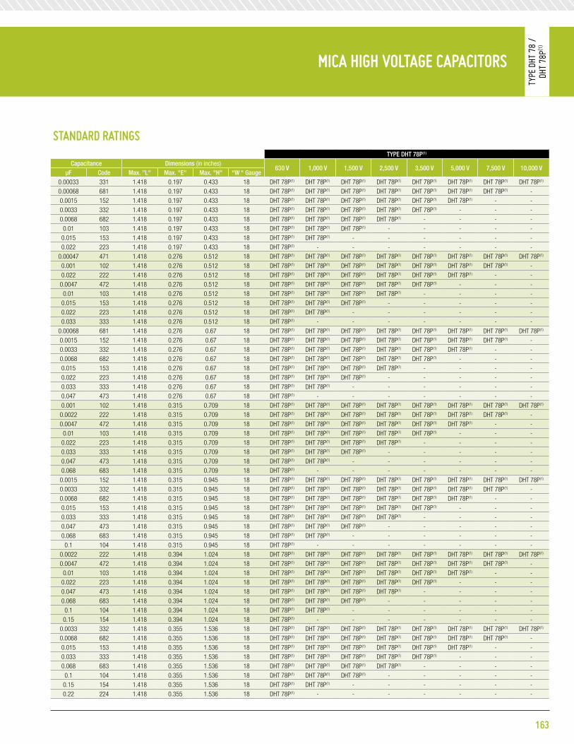
163
Wrap-and-Fill Metalized polypHenyleneSulFide FilM CapaCitorS
Type
832
p
MiCa HigH Voltage CapaCitorS
Type
DHT
78
/
DHT
78p(1
)
Standard ratingStype Dht 78p(1)
Capacitance Dimensions (in inches)630 V 1,000 V 1,500 V 2,500 V 3,500 V 5,000 V 7,500 V 10,000 V
μF Code max. "l" max. "e" max. "h" “w “ gauge0.00033 331 1.418 0.197 0.433 18 DHT 78P(1) DHT 78P(1) DHT 78P(1) DHT 78P(1) DHT 78P(1) DHT 78P(1) DHT 78P(1) DHT 78P(1)
0.00068 681 1.418 0.197 0.433 18 DHT 78P(1) DHT 78P(1) DHT 78P(1) DHT 78P(1) DHT 78P(1) DHT 78P(1) DHT 78P(1) -0.0015 152 1.418 0.197 0.433 18 DHT 78P(1) DHT 78P(1) DHT 78P(1) DHT 78P(1) DHT 78P(1) DHT 78P(1) - -0.0033 332 1.418 0.197 0.433 18 DHT 78P(1) DHT 78P(1) DHT 78P(1) DHT 78P(1) DHT 78P(1) - - -0.0068 682 1.418 0.197 0.433 18 DHT 78P(1) DHT 78P(1) DHT 78P(1) DHT 78P(1) - - - -
0.01 103 1.418 0.197 0.433 18 DHT 78P(1) DHT 78P(1) DHT 78P(1) - - - - -0.015 153 1.418 0.197 0.433 18 DHT 78P(1) DHT 78P(1) - - - - - -0.022 223 1.418 0.197 0.433 18 DHT 78P(1) - - - - - - -
0.00047 471 1.418 0.276 0.512 18 DHT 78P(1) DHT 78P(1) DHT 78P(1) DHT 78P(1) DHT 78P(1) DHT 78P(1) DHT 78P(1) DHT 78P(1)
0.001 102 1.418 0.276 0.512 18 DHT 78P(1) DHT 78P(1) DHT 78P(1) DHT 78P(1) DHT 78P(1) DHT 78P(1) DHT 78P(1) -0.022 222 1.418 0.276 0.512 18 DHT 78P(1) DHT 78P(1) DHT 78P(1) DHT 78P(1) DHT 78P(1) DHT 78P(1) - -0.0047 472 1.418 0.276 0.512 18 DHT 78P(1) DHT 78P(1) DHT 78P(1) DHT 78P(1) DHT 78P(1) - - -
0.01 103 1.418 0.276 0.512 18 DHT 78P(1) DHT 78P(1) DHT 78P(1) DHT 78P(1) - - - -0.015 153 1.418 0.276 0.512 18 DHT 78P(1) DHT 78P(1) DHT 78P(1) - - - - -0.022 223 1.418 0.276 0.512 18 DHT 78P(1) DHT 78P(1) - - - - - -0.033 333 1.418 0.276 0.512 18 DHT 78P(1) - - - - - - -
0.00068 681 1.418 0.276 0.67 18 DHT 78P(1) DHT 78P(1) DHT 78P(1) DHT 78P(1) DHT 78P(1) DHT 78P(1) DHT 78P(1) DHT 78P(1)
0.0015 152 1.418 0.276 0.67 18 DHT 78P(1) DHT 78P(1) DHT 78P(1) DHT 78P(1) DHT 78P(1) DHT 78P(1) DHT 78P(1) -0.0033 332 1.418 0.276 0.67 18 DHT 78P(1) DHT 78P(1) DHT 78P(1) DHT 78P(1) DHT 78P(1) DHT 78P(1) - -0.0068 682 1.418 0.276 0.67 18 DHT 78P(1) DHT 78P(1) DHT 78P(1) DHT 78P(1) DHT 78P(1) - - -0.015 153 1.418 0.276 0.67 18 DHT 78P(1) DHT 78P(1) DHT 78P(1) DHT 78P(1) - - - -0.022 223 1.418 0.276 0.67 18 DHT 78P(1) DHT 78P(1) DHT 78P(1) - - - - -0.033 333 1.418 0.276 0.67 18 DHT 78P(1) DHT 78P(1) - - - - - -0.047 473 1.418 0.276 0.67 18 DHT 78P(1) - - - - - - -0.001 102 1.418 0.315 0.709 18 DHT 78P(1) DHT 78P(1) DHT 78P(1) DHT 78P(1) DHT 78P(1) DHT 78P(1) DHT 78P(1) DHT 78P(1)
0.0022 222 1.418 0.315 0.709 18 DHT 78P(1) DHT 78P(1) DHT 78P(1) DHT 78P(1) DHT 78P(1) DHT 78P(1) DHT 78P(1) -0.0047 472 1.418 0.315 0.709 18 DHT 78P(1) DHT 78P(1) DHT 78P(1) DHT 78P(1) DHT 78P(1) DHT 78P(1) - -
0.01 103 1.418 0.315 0.709 18 DHT 78P(1) DHT 78P(1) DHT 78P(1) DHT 78P(1) DHT 78P(1) - - -0.022 223 1.418 0.315 0.709 18 DHT 78P(1) DHT 78P(1) DHT 78P(1) DHT 78P(1) - - - -0.033 333 1.418 0.315 0.709 18 DHT 78P(1) DHT 78P(1) DHT 78P(1) - - - - -0.047 473 1.418 0.315 0.709 18 DHT 78P(1) DHT 78P(1) - - - - - -0.068 683 1.418 0.315 0.709 18 DHT 78P(1) - - - - - - -0.0015 152 1.418 0.315 0.945 18 DHT 78P(1) DHT 78P(1) DHT 78P(1) DHT 78P(1) DHT 78P(1) DHT 78P(1) DHT 78P(1) DHT 78P(1)
0.0033 332 1.418 0.315 0.945 18 DHT 78P(1) DHT 78P(1) DHT 78P(1) DHT 78P(1) DHT 78P(1) DHT 78P(1) DHT 78P(1) -0.0068 682 1.418 0.315 0.945 18 DHT 78P(1) DHT 78P(1) DHT 78P(1) DHT 78P(1) DHT 78P(1) DHT 78P(1) - -0.015 153 1.418 0.315 0.945 18 DHT 78P(1) DHT 78P(1) DHT 78P(1) DHT 78P(1) DHT 78P(1) - - -0.033 333 1.418 0.315 0.945 18 DHT 78P(1) DHT 78P(1) DHT 78P(1) DHT 78P(1) - - - -0.047 473 1.418 0.315 0.945 18 DHT 78P(1) DHT 78P(1) DHT 78P(1) - - - - -0.068 683 1.418 0.315 0.945 18 DHT 78P(1) DHT 78P(1) - - - - - -
0.1 104 1.418 0.315 0.945 18 DHT 78P(1) - - - - - - -0.0022 222 1.418 0.394 1.024 18 DHT 78P(1) DHT 78P(1) DHT 78P(1) DHT 78P(1) DHT 78P(1) DHT 78P(1) DHT 78P(1) DHT 78P(1)
0.0047 472 1.418 0.394 1.024 18 DHT 78P(1) DHT 78P(1) DHT 78P(1) DHT 78P(1) DHT 78P(1) DHT 78P(1) DHT 78P(1) -0.01 103 1.418 0.394 1.024 18 DHT 78P(1) DHT 78P(1) DHT 78P(1) DHT 78P(1) DHT 78P(1) DHT 78P(1) - -0.022 223 1.418 0.394 1.024 18 DHT 78P(1) DHT 78P(1) DHT 78P(1) DHT 78P(1) DHT 78P(1) - - -0.047 473 1.418 0.394 1.024 18 DHT 78P(1) DHT 78P(1) DHT 78P(1) DHT 78P(1) - - - -0.068 683 1.418 0.394 1.024 18 DHT 78P(1) DHT 78P(1) DHT 78P(1) - - - - -
0.1 104 1.418 0.394 1.024 18 DHT 78P(1) DHT 78P(1) - - - - - -0.15 154 1.418 0.394 1.024 18 DHT 78P(1) - - - - - - -
0.0033 332 1.418 0.355 1.536 18 DHT 78P(1) DHT 78P(1) DHT 78P(1) DHT 78P(1) DHT 78P(1) DHT 78P(1) DHT 78P(1) DHT 78P(1)
0.0068 682 1.418 0.355 1.536 18 DHT 78P(1) DHT 78P(1) DHT 78P(1) DHT 78P(1) DHT 78P(1) DHT 78P(1) DHT 78P(1) -0.015 153 1.418 0.355 1.536 18 DHT 78P(1) DHT 78P(1) DHT 78P(1) DHT 78P(1) DHT 78P(1) DHT 78P(1) - -0.033 333 1.418 0.355 1.536 18 DHT 78P(1) DHT 78P(1) DHT 78P(1) DHT 78P(1) DHT 78P(1) - - -0.068 683 1.418 0.355 1.536 18 DHT 78P(1) DHT 78P(1) DHT 78P(1) DHT 78P(1) - - - -
0.1 104 1.418 0.355 1.536 18 DHT 78P(1) DHT 78P(1) DHT 78P(1) - - - - -0.15 154 1.418 0.355 1.536 18 DHT 78P(1) DHT 78P(1) - - - - - -0.22 224 1.418 0.355 1.536 18 DHT 78P(1) - - - - - - -

Standard ratingStype Dht 78p(1)
Capacitance Dimensions (in inches)630 V 1,000 V 1,500 V 2,500 V 3,500 V 5,000 V 7,500 V 10,000 V
μF Code max. "l" max. "e" max. "h" “w “ gauge0.0047 472 1.418 0.473 1.654 18 DHT 78P(1) DHT 78P(1) DHT 78P(1) DHT 78P(1) DHT 78P(1) DHT 78P(1) DHT 78P(1) DHT 78P(1)
0.01 103 1.418 0.473 1.654 18 DHT 78P(1) DHT 78P(1) DHT 78P(1) DHT 78P(1) DHT 78P(1) DHT 78P(1) DHT 78P(1) -0.022 223 1.418 0.473 1.654 18 DHT 78P(1) DHT 78P(1) DHT 78P(1) DHT 78P(1) DHT 78P(1) DHT 78P(1) - -0.047 473 1.418 0.473 1.654 18 DHT 78P(1) DHT 78P(1) DHT 78P(1) DHT 78P(1) DHT 78P(1) - - -
0.1 104 1.418 0.473 1.654 18 DHT 78P(1) DHT 78P(1) DHT 78P(1) DHT 78P(1) - - - -0.15 154 1.418 0.473 1.654 18 DHT 78P(1) DHT 78P(1) DHT 78P(1) - - - - -0.22 224 1.418 0.473 1.654 18 DHT 78P(1) DHT 78P(1) - - - - - -0.33 334 1.418 0.473 1.654 18 DHT 78P(1) - - - - - - -
0.0068 682 2.441 0.315 1.496 18 DHT 78P(1) DHT 78P(1) DHT 78P(1) DHT 78P(1) DHT 78P(1) DHT 78P(1) DHT 78P(1) DHT 78P(1)
0.015 153 2.441 0.315 1.496 18 DHT 78P(1) DHT 78P(1) DHT 78P(1) DHT 78P(1) DHT 78P(1) DHT 78P(1) DHT 78P(1) -0.033 333 2.441 0.315 1.496 18 DHT 78P(1) DHT 78P(1) DHT 78P(1) DHT 78P(1) DHT 78P(1) DHT 78P(1) - -0.068 683 2.441 0.315 1.496 18 DHT 78P(1) DHT 78P(1) DHT 78P(1) DHT 78P(1) DHT 78P(1) - - -0.15 154 2.441 0.315 1.496 18 DHT 78P(1) DHT 78P(1) DHT 78P(1) DHT 78P(1) - - - -0.22 224 2.441 0.315 1.496 18 DHT 78P(1) DHT 78P(1) DHT 78P(1) - - - - -0.33 334 2.441 0.315 1.496 18 DHT 78P(1) DHT 78P(1) - - - - - -0.47 474 2.441 0.315 1.496 18 DHT 78P(1) - - - - - - -0.01 103 2.441 0.355 1.929 18 DHT 78P(1) DHT 78P(1) DHT 78P(1) DHT 78P(1) DHT 78P(1) DHT 78P(1) DHT 78P(1) DHT 78P(1)
0.022 223 2.441 0.355 1.929 18 DHT 78P(1) DHT 78P(1) DHT 78P(1) DHT 78P(1) DHT 78P(1) DHT 78P(1) DHT 78P(1) -0.047 473 2.441 0.355 1.929 18 DHT 78P(1) DHT 78P(1) DHT 78P(1) DHT 78P(1) DHT 78P(1) DHT 78P(1) - -
0.1 104 2.441 0.355 1.929 18 DHT 78P(1) DHT 78P(1) DHT 78P(1) DHT 78P(1) DHT 78P(1) - - -0.22 224 2.441 0.355 1.929 18 DHT 78P(1) DHT 78P(1) DHT 78P(1) DHT 78P(1) - - - -0.33 334 2.441 0.355 1.929 18 DHT 78P(1) DHT 78P(1) DHT 78P(1) - - - - -0.47 474 2.441 0.355 1.929 18 DHT 78P(1) DHT 78P(1) - - - - - -0.68 684 2.441 0.355 1.929 18 DHT 78P(1) - - - - - - -0.015 153 2.441 0.433 2.008 18 DHT 78P(1) DHT 78P(1) DHT 78P(1) DHT 78P(1) DHT 78P(1) DHT 78P(1) DHT 78P(1) DHT 78P(1)
0.033 333 2.441 0.433 2.008 18 DHT 78P(1) DHT 78P(1) DHT 78P(1) DHT 78P(1) DHT 78P(1) DHT 78P(1) DHT 78P(1) -0.068 683 2.441 0.433 2.008 18 DHT 78P(1) DHT 78P(1) DHT 78P(1) DHT 78P(1) DHT 78P(1) DHT 78P(1) - -0.15 154 2.441 0.433 2.008 18 DHT 78P(1) DHT 78P(1) DHT 78P(1) DHT 78P(1) DHT 78P(1) - - -0.33 334 2.441 0.433 2.008 18 DHT 78P(1) DHT 78P(1) DHT 78P(1) DHT 78P(1) - - - -0.47 474 2.441 0.433 2.008 18 DHT 78P(1) DHT 78P(1) DHT 78P(1) - - - - -0.68 684 2.441 0.433 2.008 18 DHT 78P(1) DHT 78P(1) - - - - - -
1 105 2.441 0.433 2.008 18 DHT 78P(1) - - - - - - -0.022 223 2.441 0.551 2.126 18 DHT 78P(1) DHT 78P(1) DHT 78P(1) DHT 78P(1) DHT 78P(1) DHT 78P(1) DHT 78P(1) DHT 78P(1)
0.047 473 2.441 0.551 2.126 18 DHT 78P(1) DHT 78P(1) DHT 78P(1) DHT 78P(1) DHT 78P(1) DHT 78P(1) DHT 78P(1) -0.1 104 2.441 0.551 2.126 18 DHT 78P(1) DHT 78P(1) DHT 78P(1) DHT 78P(1) DHT 78P(1) DHT 78P(1) - -0.22 224 2.441 0.551 2.126 18 DHT 78P(1) DHT 78P(1) DHT 78P(1) DHT 78P(1) DHT 78P(1) - - -0.47 474 2.441 0.551 2.126 18 DHT 78P(1) DHT 78P(1) DHT 78P(1) DHT 78P(1) - - - -0.68 684 2.441 0.551 2.126 18 DHT 78P(1) DHT 78P(1) DHT 78P(1) - - - - -
1 105 2.441 0.551 2.126 18 DHT 78P(1) DHT 78P(1) - - - - - -1.5 155 2.441 0.551 2.126 18 DHT 78P(1) - - - - - - -
0.033 333 3.15 0.473 2.047 16 - DHT 78P(1) DHT 78P(1) DHT 78P(1) DHT 78P(1) DHT 78P(1) DHT 78P(1) DHT 78P(1)
0.068 683 3.15 0.473 2.047 16 - DHT 78P(1) DHT 78P(1) DHT 78P(1) DHT 78P(1) DHT 78P(1) DHT 78P(1) -0.15 154 3.15 0.473 2.047 16 - DHT 78P(1) DHT 78P(1) DHT 78P(1) DHT 78P(1) DHT 78P(1) - -0.33 334 3.15 0.473 2.047 16 - DHT 78P(1) DHT 78P(1) DHT 78P(1) DHT 78P(1) - - -0.68 684 3.15 0.473 2.047 16 - DHT 78P(1) DHT 78P(1) DHT 78P(1) - - - -
1 105 3.15 0.473 2047 16 - DHT 78P(1) DHT 78P(1) - - - - -1.5 155 3.15 0.473 2.047 16 - DHT 78P(1) - - - - - -
0.047 473 3.15 0.748 1.929 16 - - DHT 78P(1) DHT 78P(1) DHT 78P(1) DHT 78P(1) DHT 78P(1) DHT 78P(1)
0.1 104 3.15 0.748 1.929 16 - - DHT 78P(1) DHT 78P(1) DHT 78P(1) DHT 78P(1) DHT 78P(1) -0.22 224 3.15 0.748 1.929 16 - - DHT 78P(1) DHT 78P(1) DHT 78P(1) DHT 78P(1) - -0.47 474 3.15 0.748 1.929 16 - - DHT 78P(1) DHT 78P(1) DHT 78P(1) - - -
1 105 3.15 0.748 1.929 16 - - DHT 78P(1) DHT 78P(1) - - - -1.5 155 3.15 0.748 1.929 16 - - DHT 78P(1) - - - - -
MiCa HigH Voltage CapaCitorS
Type
DHT
78
/
DHT
78p(1
)
164

165
Wrap-and-Fill Metalized polypHenyleneSulFide FilM CapaCitorS
Type
832
p
MiCa HigH Voltage CapaCitorS
Type
DHT
86
/
DHT
86p(1
)
eleCtriCal SpeCiFiCationSopeRating tempeRatuRe Range:- 55°C to +125°C
Dissipation FaCtoR:≤ 0.7% @ 1kHz for CR ≤ 1.5nF≤ 0.5% @ 1kHz for CR > 1.5nF
insulation ResistanCe (iR):≥ 25,000 MΩ for CR ≤ 0.22 μF≥ 5,000 MΩ.μF for CR > 0.22 μF
DieleCtRiC withstanDing Voltage (DwV):1.6 x rated voltage
insulation Between leaDs & Case:25,000 MΩ
CapaCitanCe toleRanCes aVailaBle:±20%, ±10%, ±5%
diMenSionS (in inches)
pHySiCal CHaraCteriStiCSConstRuCtion:Metal foils, non- inductive.
Case:• Composite reconstituted mica• Epoxy resin impregnated• Polyester wrapped• Epoxy resin sealed
maRking:Dearborn trademark, type or catalog number, capacitance, tolerance and voltage.
note: P(1) Premolded capacitor for dielectric fluid use or encapsulation.
L
W
H
> 0.99
E
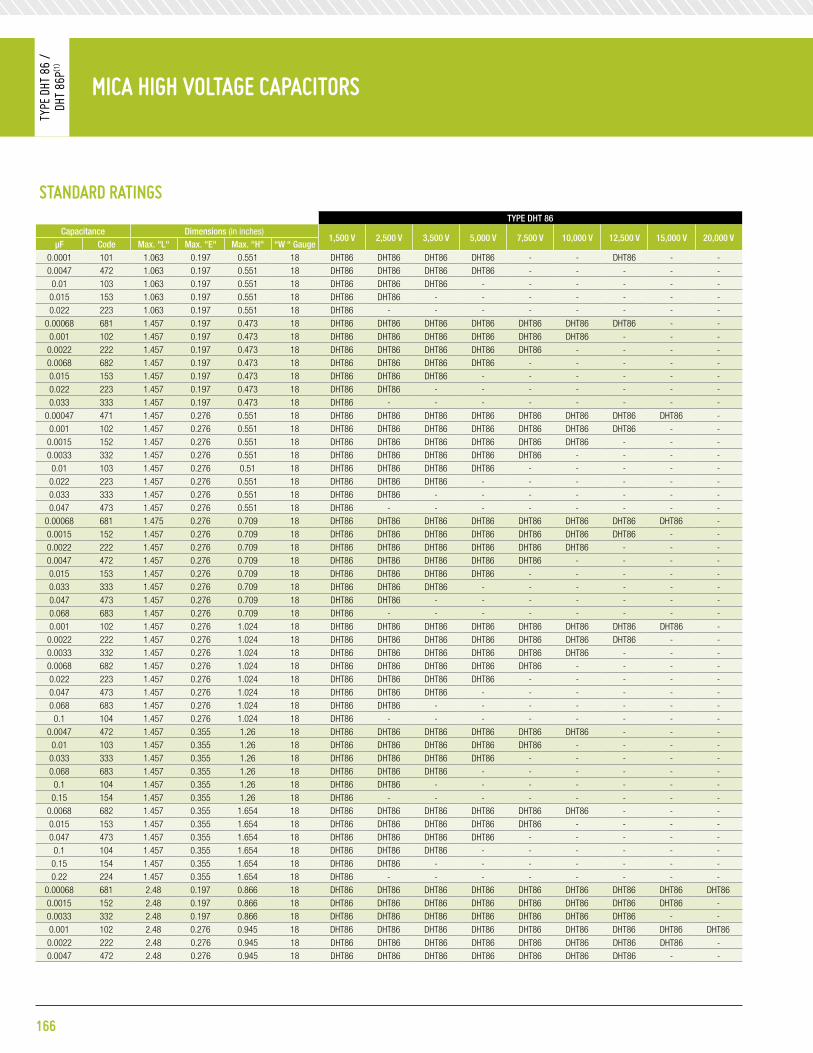
Standard ratingStype Dht 86
Capacitance Dimensions (in inches)1,500 V 2,500 V 3,500 V 5,000 V 7,500 V 10,000 V 12,500 V 15,000 V 20,000 V
μF Code max. "l" max. "e" max. "h" “w “ gauge0.0001 101 1.063 0.197 0.551 18 DHT86 DHT86 DHT86 DHT86 - - DHT86 - -0.0047 472 1.063 0.197 0.551 18 DHT86 DHT86 DHT86 DHT86 - - - - -0.01 103 1.063 0.197 0.551 18 DHT86 DHT86 DHT86 - - - - - -
0.015 153 1.063 0.197 0.551 18 DHT86 DHT86 - - - - - - -0.022 223 1.063 0.197 0.551 18 DHT86 - - - - - - - -
0.00068 681 1.457 0.197 0.473 18 DHT86 DHT86 DHT86 DHT86 DHT86 DHT86 DHT86 - -0.001 102 1.457 0.197 0.473 18 DHT86 DHT86 DHT86 DHT86 DHT86 DHT86 - - -
0.0022 222 1.457 0.197 0.473 18 DHT86 DHT86 DHT86 DHT86 DHT86 - - - -0.0068 682 1.457 0.197 0.473 18 DHT86 DHT86 DHT86 DHT86 - - - - -0.015 153 1.457 0.197 0.473 18 DHT86 DHT86 DHT86 - - - - - -0.022 223 1.457 0.197 0.473 18 DHT86 DHT86 - - - - - - -0.033 333 1.457 0.197 0.473 18 DHT86 - - - - - - - -
0.00047 471 1.457 0.276 0.551 18 DHT86 DHT86 DHT86 DHT86 DHT86 DHT86 DHT86 DHT86 -0.001 102 1.457 0.276 0.551 18 DHT86 DHT86 DHT86 DHT86 DHT86 DHT86 DHT86 - -
0.0015 152 1.457 0.276 0.551 18 DHT86 DHT86 DHT86 DHT86 DHT86 DHT86 - - -0.0033 332 1.457 0.276 0.551 18 DHT86 DHT86 DHT86 DHT86 DHT86 - - - -0.01 103 1.457 0.276 0.51 18 DHT86 DHT86 DHT86 DHT86 - - - - -
0.022 223 1.457 0.276 0.551 18 DHT86 DHT86 DHT86 - - - - - -0.033 333 1.457 0.276 0.551 18 DHT86 DHT86 - - - - - - -0.047 473 1.457 0.276 0.551 18 DHT86 - - - - - - - -
0.00068 681 1.475 0.276 0.709 18 DHT86 DHT86 DHT86 DHT86 DHT86 DHT86 DHT86 DHT86 -0.0015 152 1.457 0.276 0.709 18 DHT86 DHT86 DHT86 DHT86 DHT86 DHT86 DHT86 - -0.0022 222 1.457 0.276 0.709 18 DHT86 DHT86 DHT86 DHT86 DHT86 DHT86 - - -0.0047 472 1.457 0.276 0.709 18 DHT86 DHT86 DHT86 DHT86 DHT86 - - - -0.015 153 1.457 0.276 0.709 18 DHT86 DHT86 DHT86 DHT86 - - - - -0.033 333 1.457 0.276 0.709 18 DHT86 DHT86 DHT86 - - - - - -0.047 473 1.457 0.276 0.709 18 DHT86 DHT86 - - - - - - -0.068 683 1.457 0.276 0.709 18 DHT86 - - - - - - - -0.001 102 1.457 0.276 1.024 18 DHT86 DHT86 DHT86 DHT86 DHT86 DHT86 DHT86 DHT86 -
0.0022 222 1.457 0.276 1.024 18 DHT86 DHT86 DHT86 DHT86 DHT86 DHT86 DHT86 - -0.0033 332 1.457 0.276 1.024 18 DHT86 DHT86 DHT86 DHT86 DHT86 DHT86 - - -0.0068 682 1.457 0.276 1.024 18 DHT86 DHT86 DHT86 DHT86 DHT86 - - - -0.022 223 1.457 0.276 1.024 18 DHT86 DHT86 DHT86 DHT86 - - - - -0.047 473 1.457 0.276 1.024 18 DHT86 DHT86 DHT86 - - - - - -0.068 683 1.457 0.276 1.024 18 DHT86 DHT86 - - - - - - -0.1 104 1.457 0.276 1.024 18 DHT86 - - - - - - - -
0.0047 472 1.457 0.355 1.26 18 DHT86 DHT86 DHT86 DHT86 DHT86 DHT86 - - -0.01 103 1.457 0.355 1.26 18 DHT86 DHT86 DHT86 DHT86 DHT86 - - - -
0.033 333 1.457 0.355 1.26 18 DHT86 DHT86 DHT86 DHT86 - - - - -0.068 683 1.457 0.355 1.26 18 DHT86 DHT86 DHT86 - - - - - -0.1 104 1.457 0.355 1.26 18 DHT86 DHT86 - - - - - - -
0.15 154 1.457 0.355 1.26 18 DHT86 - - - - - - - -0.0068 682 1.457 0.355 1.654 18 DHT86 DHT86 DHT86 DHT86 DHT86 DHT86 - - -0.015 153 1.457 0.355 1.654 18 DHT86 DHT86 DHT86 DHT86 DHT86 - - - -0.047 473 1.457 0.355 1.654 18 DHT86 DHT86 DHT86 DHT86 - - - - -0.1 104 1.457 0.355 1.654 18 DHT86 DHT86 DHT86 - - - - - -
0.15 154 1.457 0.355 1.654 18 DHT86 DHT86 - - - - - - -0.22 224 1.457 0.355 1.654 18 DHT86 - - - - - - - -
0.00068 681 2.48 0.197 0.866 18 DHT86 DHT86 DHT86 DHT86 DHT86 DHT86 DHT86 DHT86 DHT860.0015 152 2.48 0.197 0.866 18 DHT86 DHT86 DHT86 DHT86 DHT86 DHT86 DHT86 DHT86 -0.0033 332 2.48 0.197 0.866 18 DHT86 DHT86 DHT86 DHT86 DHT86 DHT86 DHT86 - -0.001 102 2.48 0.276 0.945 18 DHT86 DHT86 DHT86 DHT86 DHT86 DHT86 DHT86 DHT86 DHT860.0022 222 2.48 0.276 0.945 18 DHT86 DHT86 DHT86 DHT86 DHT86 DHT86 DHT86 DHT86 -0.0047 472 2.48 0.276 0.945 18 DHT86 DHT86 DHT86 DHT86 DHT86 DHT86 DHT86 - -
MiCa HigH Voltage CapaCitorS
Type
DHT
86
/
DHT
86p(1
)
166

Standard ratingStype Dht 86
Capacitance Dimensions (in inches)1,500 V 2,500 V 3,500 V 5,000 V 7,500 V 10,000 V 12,500 V 15,000 V 20,000 V
μF Code max. "l" max. "e" max. "h" “w “ gauge0.0015 152 2.48 0.355 1.024 18 DHT86 DHT86 DHT86 DHT86 DHT86 DHT86 DHT86 DHT86 DHT860.0033 332 2.48 0.355 1.024 18 DHT86 DHT86 DHT86 DHT86 DHT86 DHT86 DHT86 DHT86 -0.0068 682 2.48 0.355 1.024 18 DHT86 DHT86 DHT86 DHT86 DHT86 DHT86 DHT86 - -0.01 103 2.48 0.355 1.024 18 DHT86 DHT86 DHT86 DHT86 DHT86 DHT86 - - -
0.022 223 2.48 0.355 1.024 18 DHT86 DHT86 DHT86 DHT86 DHT86 - - - -0.068 683 2.48 0.355 1.024 18 DHT86 DHT86 DHT86 DHT86 - - - - -0.15 154 2.48 0.355 1.024 18 DHT86 DHT86 DHT86 - - - - - -0.33 334 2.48 0.355 1.024 18 DHT86 - - - - - - - -
0.0022 222 2.48 0.355 1.575 18 DHT86 DHT86 DHT86 DHT86 DHT86 DHT86 DHT86 DHT86 DHT860.0047 472 2.48 0.355 1.575 18 DHT86 DHT86 DHT86 DHT86 DHT86 DHT86 DHT86 DHT86 -0.01 103 2.48 0.355 1.575 18 DHT86 DHT86 DHT86 DHT86 DHT86 DHT86 DHT86 - -
0.015 153 2.48 0.355 1.575 18 DHT86 DHT86 DHT86 DHT86 DHT86 DHT86 - - -0.033 333 2.48 0.355 1.575 18 DHT86 DHT86 DHT86 DHT86 DHT86 - - - -0.1 104 2.48 0.355 1.575 18 DHT86 DHT86 DHT86 DHT86 - - - - -
0.22 224 2.48 0.355 1.575 18 DHT86 DHT86 - - - - - - -0.47 474 2.48 0.355 1.575 18 DHT86 - - - - - - - -
0.0033 332 2.48 0.355 1.851 18 DHT86 DHT86 DHT86 DHT86 DHT86 DHT86 DHT86 DHT86 DHT860.0068 682 2.48 0.355 1.851 18 DHT86 DHT86 DHT86 DHT86 DHT86 DHT86 DHT86 DHT86 -0.015 153 2.48 0.355 1.851 18 DHT86 DHT86 DHT86 DHT86 DHT86 DHT86 DHT86 - -0.022 223 2.48 0.355 1.851 18 DHT86 DHT86 DHT86 DHT86 DHT86 DHT86 - - -0.047 473 2.48 0.355 1.851 18 DHT86 DHT86 DHT86 DHT86 DHT86 - - - -0.22 224 2.48 0.355 1.851 18 DHT86 DHT86 DHT86 - - - - - -0.33 334 2.48 0.355 1.851 18 DHT86 DHT86 - - - - - - -
0.0047 472 3.189 0.355 1.851 16 DHT86 DHT86 DHT86 DHT86 DHT86 DHT86 DHT86 DHT86 DHT860.01 103 3.189 0.355 1.851 16 DHT86 DHT86 DHT86 DHT86 DHT86 DHT86 DHT86 DHT86 -
0.022 223 3.189 0.355 1.851 16 DHT86 DHT86 DHT86 DHT86 DHT86 DHT86 DHT86 - -0.033 333 3.189 0.355 1.851 16 DHT86 DHT86 DHT86 DHT86 DHT86 DHT86 - - -0.068 683 3.189 0.355 1.851 16 DHT86 DHT86 DHT86 DHT86 DHT86 - - - -0.15 154 3.189 0.355 1.851 16 DHT86 DHT86 DHT86 DHT86 - - - - -0.33 334 3.189 0.355 1.851 16 DHT86 DHT86 DHT86 - - - - - -0.47 474 3.189 0.355 1.851 16 DHT86 DHT86 - - - - - - -0.68 684 3.189 0.355 1.851 16 DHT86 - - - - - - - -
0.0068 682 3.189 0.433 1.292 16 DHT86 DHT86 DHT86 DHT86 DHT86 DHT86 DHT86 DHT86 DHT860.015 153 3.189 0.433 1.929 16 DHT86 DHT86 DHT86 DHT86 DHT86 DHT86 DHT86 DHT86 -0.033 333 3.189 0.433 1.929 16 DHT86 DHT86 DHT86 DHT86 DHT86 DHT86 DHT86 - -0.047 473 3.189 0.433 1.929 16 DHT86 DHT86 DHT86 DHT86 DHT86 DHT86 - - -0.1 104 3.189 0.433 1.929 16 DHT86 DHT86 DHT86 DHT86 DHT86 - - - -
0.22 224 3.189 0.433 1.929 16 DHT86 DHT86 DHT86 DHT86 - - - - -0.47 474 3.189 0.433 1.929 16 DHT86 DHT86 DHT86 - - - - - -0.68 684 3.189 0.433 1.929 16 DHT86 DHT86 - - - - - - -
1 105 3.189 0.433 1.929 16 DHT86 - - - - - - - -0.01 103 4.213 0.433 1.929 16 DHT86 DHT86 DHT86 DHT86 DHT86 DHT86 DHT86 DHT86 DHT86
0.022 223 4.213 0.433 1.929 16 DHT86 DHT86 DHT86 DHT86 DHT86 DHT86 DHT86 DHT86 -0.047 473 4.213 0.433 1.929 16 DHT86 DHT86 DHT86 DHT86 DHT86 DHT86 DHT86 - -0.068 683 4.213 0.433 1.929 16 DHT86 DHT86 DHT86 DHT86 DHT86 DHT86 - - -0.15 154 4.213 0.433 1.929 16 DHT86 DHT86 DHT86 DHT86 DHT86 - - - -0.33 334 4.213 0.433 1.929 16 DHT86 DHT86 DHT86 DHT86 - - - - -0.68 684 4.213 0.433 1.929 16 DHT86 DHT86 DHT86 - - - - - -
1 105 4.213 0.433 1.929 16 DHT86 DHT86 - - - - - - -1.5 155 4.213 0.433 1.929 16 DHT86 - - - - - - - -
167
Wrap-and-Fill Metalized polypHenyleneSulFide FilM CapaCitorS
Type
832
p
MiCa HigH Voltage CapaCitorS
Type
DHT
86
/
DHT
86p(1
)

Standard ratingStype Dht 86
Capacitance Dimensions (in inches)1,500 V 2,500 V 3,500 V 5,000 V 7,500 V 10,000 V 12,500 V 15,000 V 20,000 V
μF Code max. "l" max. "e" max. "h" “w “ gauge0.015 153 4.213 0.63 2.047 16 DHT86 DHT86 DHT86 DHT86 DHT86 DHT86 DHT86 DHT86 DHT860.033 333 4.213 0.63 2.047 16 DHT86 DHT86 DHT86 DHT86 DHT86 DHT86 DHT86 DHT86 -0.068 683 4.213 0.63 2.047 16 DHT86 DHT86 DHT86 DHT86 DHT86 DHT86 DHT86 - -0.1 104 4.213 0.63 2.047 16 DHT86 DHT86 DHT86 DHT86 DHT86 DHT86 - - -
0.22 224 4.213 0.63 2.047 16 DHT86 DHT86 DHT86 DHT86 DHT86 - - - -0.47 474 4.213 0.63 2.047 16 DHT86 DHT86 DHT86 DHT86 - - - - -
1 105 4.213 0.63 2.047 16 DHT86 DHT86 DHT86 - - - - - -1.5 155 4.213 0.63 2.047 16 DHT86 DHT86 - - - - - - -2.2 225 4.213 0.63 2.047 16 DHT86 - - - - - - - -
Standard ratingStype Dht 86p(1)
Capacitance Dimensions (in inches)1,500 V 2,500 V 3,500 V 5,000 V 7,500 V 10,000 V 12,500 V 15,000 V 20,000 V
μF Code max. "l" max. "e" max. "h" “w “ gauge0.0001 101 1.024 0.197 0.512 18 DHT 86P(1) DHT 86P(1) DHT 86P(1) DHT 86P(1) DHT 86P(1) DHT 86P(1) DHT 86P(1) - -0.0047 472 1.024 0.197 0.512 18 DHT 86P(1) DHT 86P(1) DHT 86P(1) DHT 86P(1) - - - - -0.01 103 1.024 0.197 0.512 18 DHT 86P(1) DHT 86P(1) DHT 86P(1) - - - - - -
0.015 153 1.024 0.197 0.512 18 DHT 86P(1) DHT 86P(1) - - - - - - -0.022 223 1.024 0.197 0.512 18 DHT 86P(1) - - - - - - - -
0.00068 681 1.418 0.197 0.433 18 DHT 86P(1) DHT 86P(1) DHT 86P(1) DHT 86P(1) DHT 86P(1) DHT 86P(1) DHT 86P(1) - -0.001 102 1.418 0.197 0.433 18 DHT 86P(1) DHT 86P(1) DHT 86P(1) DHT 86P(1) DHT 86P(1) DHT 86P(1) - - -
0.0022 222 1.418 0.197 0.433 18 DHT 86P(1) DHT 86P(1) DHT 86P(1) DHT 86P(1) DHT 86P(1) - - - -0.0068 682 1.418 0.197 0.433 18 DHT 86P(1) DHT 86P(1) DHT 86P(1) DHT 86P(1) - - - - -0.015 153 1.418 0.197 0.433 18 DHT 86P(1) DHT 86P(1) DHT 86P(1) - - - - - -0.022 223 1.418 0.197 0.433 18 DHT 86P(1) DHT 86P(1) - - - - - - -0.033 333 1.418 0.197 0.433 18 DHT 86P(1) - - - - - - - -
0.00047 471 1.418 0.276 0.512 18 DHT 86P(1) DHT 86P(1) DHT 86P(1) DHT 86P(1) DHT 86P(1) DHT 86P(1) DHT 86P(1) DHT 86P(1) -0.001 102 1.418 0.276 0.512 18 DHT 86P(1) DHT 86P(1) DHT 86P(1) DHT 86P(1) DHT 86P(1) DHT 86P(1) DHT 86P(1) - -
0.0015 152 1.418 0.276 0.512 18 DHT 86P(1) DHT 86P(1) DHT 86P(1) DHT 86P(1) DHT 86P(1) DHT 86P(1) - - -0.0033 332 1.418 0.276 0.512 18 DHT 86P(1) DHT 86P(1) DHT 86P(1) DHT 86P(1) DHT 86P(1) - - - -0.01 103 1.418 0.276 0.512 18 DHT 86P(1) DHT 86P(1) DHT 86P(1) DHT 86P(1) - - - - -
0.022 223 1.418 0.276 0.512 18 DHT 86P(1) DHT 86P(1) DHT 86P(1) - - - - - -0.033 333 1.418 0.276 0.512 18 DHT 86P(1) DHT 86P(1) - - - - - - -0.047 473 1.418 0.276 0.512 18 DHT 86P(1) - - - - - - - -
0.00068 681 1.418 0.276 0.67 18 DHT 86P(1) DHT 86P(1) DHT 86P(1) DHT 86P(1) DHT 86P(1) DHT 86P(1) DHT 86P(1) DHT 86P(1) -0.0015 152 1.418 0.276 0.67 18 DHT 86P(1) DHT 86P(1) DHT 86P(1) DHT 86P(1) DHT 86P(1) DHT 86P(1) DHT 86P(1) - -0.0022 222 1.418 0.276 0.67 18 DHT 86P(1) DHT 86P(1) DHT 86P(1) DHT 86P(1) DHT 86P(1) DHT 86P(1) - - -0.0047 472 1.418 0.276 0.67 18 DHT 86P(1) DHT 86P(1) DHT 86P(1) DHT 86P(1) DHT 86P(1) - - - -0.015 153 1.418 0.276 0.67 18 DHT 86P(1) DHT 86P(1) DHT 86P(1) DHT 86P(1) - - - - -0.033 333 1.418 0.276 0.67 18 DHT 86P(1) DHT 86P(1) DHT 86P(1) - - - - - -0.047 473 1.418 0.276 0.67 18 DHT 86P(1) DHT 86P(1) - - - - - - -0.068 683 1.418 0.276 0.67 18 DHT 86P(1) - - - - - - - -0.001 102 1.418 0.276 0.984 18 DHT 86P(1) DHT 86P(1) DHT 86P(1) DHT 86P(1) DHT 86P(1) DHT 86P(1) DHT 86P(1) DHT 86P(1) -0.0022 222 1.418 0.276 0.984 18 DHT 86P(1) DHT 86P(1) DHT 86P(1) DHT 86P(1) DHT 86P(1) DHT 86P(1) DHT 86P(1) - -0.0033 332 1.418 0.276 0.984 18 DHT 86P(1) DHT 86P(1) DHT 86P(1) DHT 86P(1) DHT 86P(1) DHT 86P(1) - - -0.0068 682 1.418 0.276 0.984 18 DHT 86P(1) DHT 86P(1) DHT 86P(1) DHT 86P(1) DHT 86P(1) - - - -0.022 223 1.418 0.276 0.984 18 DHT 86P(1) DHT 86P(1) DHT 86P(1) DHT 86P(1) - - - - -0.047 473 1.418 0.276 0.984 18 DHT 86P(1) DHT 86P(1) DHT 86P(1) - - - - - -0.068 683 1.418 0.276 0.984 18 DHT 86P(1) DHT 86P(1) - - - - - - -0.1 104 1.418 0.276 0.984 18 DHT 86P(1) - - - - - - - -
note: P(1) Premolded Capacitor for Dielectric Fluid use or Encapsulation.
MiCa HigH Voltage CapaCitorS
Type
DHT
86
/
DHT
86p(1
)
168

Standard ratingStype Dht 86p(1)
Capacitance Dimensions (in inches)1,500 V 2,500 V 3,500 V 5,000 V 7,500 V 10,000 V 12,500 V 15,000 V 20,000 V
μF Code max. "l" max. "e" max. "h" “w “ gauge0.0047 472 1.418 0.355 1.221 18 DHT 86P(1) DHT 86P(1) DHT 86P(1) DHT 86P(1) DHT 86P(1) DHT 86P(1) - - -
0.01 103 1.418 0.355 1.221 18 DHT 86P(1) DHT 86P(1) DHT 86P(1) DHT 86P(1) DHT 86P(1) - - - -0.033 333 1.418 0.355 1.221 18 DHT 86P(1) DHT 86P(1) DHT 86P(1) DHT 86P(1) - - - - -0.068 683 1.418 0.355 1.221 18 DHT 86P(1) DHT 86P(1) DHT 86P(1) - - - - - -0.1 104 1.418 0.355 1.221 18 DHT 86P(1) DHT 86P(1) - - - - - - -
0.15 154 1.418 0.355 1.221 18 DHT 86P(1) - - - - - - - -0.0068 682 1.418 0.355 1.614 18 DHT 86P(1) DHT 86P(1) DHT 86P(1) DHT 86P(1) DHT 86P(1) DHT 86P(1) - - -0.015 153 1.418 0.355 1.614 18 DHT 86P(1) DHT 86P(1) DHT 86P(1) DHT 86P(1) DHT 86P(1) - - - -0.047 473 1.418 0.355 1.614 18 DHT 86P(1) DHT 86P(1) DHT 86P(1) DHT 86P(1) - - - - -0.1 104 1.418 0.355 1.614 18 DHT 86P(1) DHT 86P(1) DHT 86P(1) - - - - - -
0.15 154 1.418 0.355 1.614 18 DHT 86P(1) DHT 86P(1) - - - - - - -0.22 224 1.418 0.355 1.614 18 DHT 86P(1) - - - - - - - -
0.00068 681 2.441 0.197 0.827 18 DHT 86P(1) DHT 86P(1) DHT 86P(1) DHT 86P(1) DHT 86P(1) DHT 86P(1) DHT 86P(1) DHT 86P(1) DHT 86P(1)
0.0015 152 2.441 0.197 0.827 18 DHT 86P(1) DHT 86P(1) DHT 86P(1) DHT 86P(1) DHT 86P(1) DHT 86P(1) DHT 86P(1) DHT 86P(1) -0.0033 332 2.441 0.197 0.827 18 DHT 86P(1) DHT 86P(1) DHT 86P(1) DHT 86P(1) DHT 86P(1) DHT 86P(1) DHT 86P(1) - -0.001 102 2.441 0.276 0.906 18 DHT 86P(1) DHT 86P(1) DHT 86P(1) DHT 86P(1) DHT 86P(1) DHT 86P(1) DHT 86P(1) DHT 86P(1) DHT 86P(1)
0.0022 222 2.441 0.276 0.906 18 DHT 86P(1) DHT 86P(1) DHT 86P(1) DHT 86P(1) DHT 86P(1) DHT 86P(1) DHT 86P(1) DHT 86P(1) -0.0047 472 2.441 0.276 0.906 18 DHT 86P(1) DHT 86P(1) DHT 86P(1) DHT 86P(1) DHT 86P(1) DHT 86P(1) DHT 86P(1) - -0.0015 152 2.441 0.355 0.984 18 DHT 86P(1) DHT 86P(1) DHT 86P(1) DHT 86P(1) DHT 86P(1) DHT 86P(1) DHT 86P(1) DHT 86P(1) DHT 86P(1)
0.0033 332 2.441 0.355 0.984 18 DHT 86P(1) DHT 86P(1) DHT 86P(1) DHT 86P(1) DHT 86P(1) DHT 86P(1) DHT 86P(1) DHT 86P(1) -0.0068 682 2.441 0.355 0.984 18 DHT 86P(1) DHT 86P(1) DHT 86P(1) DHT 86P(1) DHT 86P(1) DHT 86P(1) DHT 86P(1) - -0.01 103 2.441 0.355 0.984 18 DHT 86P(1) DHT 86P(1) DHT 86P(1) DHT 86P(1) DHT 86P(1) DHT 86P(1) - - -0.022 223 2.441 0.355 0.984 18 DHT 86P(1) DHT 86P(1) DHT 86P(1) DHT 86P(1) DHT 86P(1) - - - -0.068 683 2.441 0.355 0.984 18 DHT 86P(1) DHT 86P(1) DHT 86P(1) DHT 86P(1) - - - - -0.015 153 2.441 0.355 0.984 18 DHT 86P(1) DHT 86P(1) DHT 86P(1) - - - - - -0.033 333 2.441 0.355 0.984 18 DHT 86P(1) - - - - - - - -
0.0022 222 2.441 0.355 1.536 18 DHT 86P(1) DHT 86P(1) DHT 86P(1) DHT 86P(1) DHT 86P(1) DHT 86P(1) DHT 86P(1) DHT 86P(1) DHT 86P(1)
0.0047 472 2.441 0.355 1.536 18 DHT 86P(1) DHT 86P(1) DHT 86P(1) DHT 86P(1) DHT 86P(1) DHT 86P(1) DHT 86P(1) DHT 86P(1) -0.01 103 2.441 0.355 1.536 18 DHT 86P(1) DHT 86P(1) DHT 86P(1) DHT 86P(1) DHT 86P(1) DHT 86P(1) DHT 86P(1) - -
0.015 153 2.441 0.355 1.536 18 DHT 86P(1) DHT 86P(1) DHT 86P(1) DHT 86P(1) DHT 86P(1) DHT 86P(1) - - -0.033 335 2.441 0.355 1.536 18 DHT 86P(1) DHT 86P(1) DHT 86P(1) DHT 86P(1) DHT 86P(1) - - - -0.1 104 2.441 0.355 1.536 18 DHT 86P(1) DHT 86P(1) DHT 86P(1) DHT 86P(1) - - - - -
0.22 224 2.441 0.355 1.536 18 DHT 86P(1) DHT 86P(1) - - - - - - -0.47 474 2.441 0.355 1.536 18 DHT 86P(1) - - - - - - - -
0.0033 332 2.441 0.355 1.811 18 DHT 86P(1) DHT 86P(1) DHT 86P(1) DHT 86P(1) DHT 86P(1) DHT 86P(1) DHT 86P(1) DHT 86P(1) DHT 86P(1)
0.0068 682 2.441 0.355 1.811 18 DHT 86P(1) DHT 86P(1) DHT 86P(1) DHT 86P(1) DHT 86P(1) DHT 86P(1) DHT 86P(1) DHT 86P(1) -0.015 153 2.441 0.355 1.811 18 DHT 86P(1) DHT 86P(1) DHT 86P(1) DHT 86P(1) DHT 86P(1) DHT 86P(1) DHT 86P(1) - -0.022 223 2.441 0.355 1.811 18 DHT 86P(1) DHT 86P(1) DHT 86P(1) DHT 86P(1) DHT 86P(1) DHT 86P(1) - - -0.047 473 2.441 0.355 1.811 18 DHT 86P(1) DHT 86P(1) DHT 86P(1) DHT 86P(1) DHT 86P(1) - - - -0.022 223 2.441 0.355 1.811 18 DHT 86P(1) DHT 86P(1) DHT 86P(1) DHT 86P(1) - - - - -0.033 333 2.441 0.355 1.811 18 DHT 86P(1) DHT 86P(1) DHT 86P(1) - - - - - -
0.0047 472 3.15 0.355 1.811 16 DHT 86P(1) DHT 86P(1) DHT 86P(1) DHT 86P(1) DHT 86P(1) DHT 86P(1) DHT 86P(1) DHT 86P(1) DHT 86P(1)
0.01 103 3.15 0.355 1.811 16 DHT 86P(1) DHT 86P(1) DHT 86P(1) DHT 86P(1) DHT 86P(1) DHT 86P(1) DHT 86P(1) DHT 86P(1) -0.022 223 3.15 0.355 1.811 16 DHT 86P(1) DHT 86P(1) DHT 86P(1) DHT 86P(1) DHT 86P(1) DHT 86P(1) DHT 86P(1) - -0.033 333 3.15 0.355 1.811 16 DHT 86P(1) DHT 86P(1) DHT 86P(1) DHT 86P(1) DHT 86P(1) DHT 86P(1) - - -0.068 683 3.15 0.355 1.811 16 DHT 86P(1) DHT 86P(1) DHT 86P(1) DHT 86P(1) DHT 86P(1) - - - -0.15 154 3.15 0.355 1.811 16 DHT 86P(1) DHT 86P(1) DHT 86P(1) DHT 86P(1) - - - - -0.33 334 3.15 0.355 1.811 16 DHT 86P(1) DHT 86P(1) - - - - - - -0.47 474 3.15 0.355 1.811 16 DHT 86P(1) - - - - - - - -0.68 684 3.15 0.355 1.811 16 DHT 86P(1) - - - - - - - -
note: P(1) Premolded Capacitor for Dielectric Fluid use or Encapsulation.
169
Wrap-and-Fill Metalized polypHenyleneSulFide FilM CapaCitorS
Type
832
p
MiCa HigH Voltage CapaCitorS
Type
DHT
86
/
DHT
86p(1
)

Standard ratingStype Dht 86p(1)
Capacitance Dimensions (in inches)1,500 V 2,500 V 3,500 V 5,000 V 7,500 V 10,000 V 12,500 V 15,000 V 20,000 V
μF Code max. "l" max. "e" max. "h" “w “ gauge0.0068 682 3.15 0.433 1.89 16 DHT 86P(1) DHT 86P(1) DHT 86P(1) DHT 86P(1) DHT 86P(1) DHT 86P(1) DHT 86P(1) DHT 86P(1) DHT 86P(1)
0.015 153 3.15 0.433 1.89 16 DHT 86P(1) DHT 86P(1) DHT 86P(1) DHT 86P(1) DHT 86P(1) DHT 86P(1) DHT 86P(1) DHT 86P(1) -0.033 333 3.15 0.433 1.89 16 DHT 86P(1) DHT 86P(1) DHT 86P(1) DHT 86P(1) DHT 86P(1) DHT 86P(1) DHT 86P(1) - -0.047 473 3.15 0.433 1.89 16 DHT 86P(1) DHT 86P(1) DHT 86P(1) DHT 86P(1) DHT 86P(1) DHT 86P(1) - - -0.1 104 3.15 0.433 1.89 16 DHT 86P(1) DHT 86P(1) DHT 86P(1) DHT 86P(1) DHT 86P(1) - - - -0.22 224 3.15 0.433 1.89 16 DHT 86P(1) DHT 86P(1) DHT 86P(1) DHT 86P(1) - - - - -0.47 474 3.15 0.433 1.89 16 DHT 86P(1) DHT 86P(1) DHT 86P(1) - - - - - -0.68 684 3.15 0.433 1.89 16 DHT 86P(1) DHT 86P(1) - - - - - - -
1 105 3.15 0.433 1.89 16 DHT 86P(1) - - - - - - - -0.01 103 4.173 0.433 1.89 16 DHT 86P(1) DHT 86P(1) DHT 86P(1) DHT 86P(1) DHT 86P(1) DHT 86P(1) DHT 86P(1) DHT 86P(1) DHT 86P(1)
0.022 223 4.173 0.433 1.89 16 DHT 86P(1) DHT 86P(1) DHT 86P(1) DHT 86P(1) DHT 86P(1) DHT 86P(1) DHT 86P(1) DHT 86P(1) -0.047 473 4.173 0.433 1.89 16 DHT 86P(1) DHT 86P(1) DHT 86P(1) DHT 86P(1) DHT 86P(1) DHT 86P(1) DHT 86P(1) - -0.068 683 4.173 0.433 1.89 16 DHT 86P(1) DHT 86P(1) DHT 86P(1) DHT 86P(1) DHT 86P(1) DHT 86P(1) - - -0.15 154 4.173 0.433 1.89 16 DHT 86P(1) DHT 86P(1) DHT 86P(1) DHT 86P(1) DHT 86P(1) - - - -0.33 334 4.173 0.433 1.89 16 DHT 86P(1) DHT 86P(1) DHT 86P(1) DHT 86P(1) - - - - -0.68 684 4.173 0.433 1.89 16 DHT 86P(1) DHT 86P(1) DHT 86P(1) - - - - - -
1 105 4.173 0.433 1.89 16 DHT 86P(1) DHT 86P(1) - - - - - - -1.5 155 4.173 0.433 1.89 16 DHT 86P(1) - - - - - - - -
0.015 153 4.173 0.591 2.01 16 DHT 86P(1) DHT 86P(1) DHT 86P(1) DHT 86P(1) DHT 86P(1) DHT 86P(1) DHT 86P(1) DHT 86P(1) DHT 86P(1)
0.033 333 4.173 0.591 2.01 16 DHT 86P(1) DHT 86P(1) DHT 86P(1) DHT 86P(1) DHT 86P(1) DHT 86P(1) DHT 86P(1) DHT 86P(1) -0.068 683 4.173 0.591 2.01 16 DHT 86P(1) DHT 86P(1) DHT 86P(1) DHT 86P(1) DHT 86P(1) DHT 86P(1) DHT 86P(1) - -0.1 104 4.173 0.591 2.01 16 DHT 86P(1) DHT 86P(1) DHT 86P(1) DHT 86P(1) DHT 86P(1) DHT 86P(1) - - -0.22 224 4.173 0.591 2.01 16 DHT 86P(1) DHT 86P(1) DHT 86P(1) DHT 86P(1) DHT 86P(1) - - - -0.47 474 4.173 0.591 2.01 16 DHT 86P(1) DHT 86P(1) DHT 86P(1) DHT 86P(1) - - - - -
1 105 4.173 0.591 2.01 16 DHT 86P(1) DHT 86P(1) DHT 86P(1) - - - - - -1.5 155 4.173 0.591 2.01 16 DHT 86P(1) DHT 86P(1) - - - - - - -2.2 225 4.173 0.591 2.01 16 DHT 86P(1) - - - - - - - -
note: P(1) Premolded Capacitor for Dielectric Fluid use or Encapsulation.
MiCa HigH Voltage CapaCitorS
Type
DHT
86
/
DHT
86p(1
)
170

171
Wrap-and-Fill Metalized polypHenyleneSulFide FilM CapaCitorS
Type
832
p
MiCa HigH Voltage CapaCitorS
Type
DHT
96
eleCtriCal SpeCiFiCationSopeRating tempeRatuRe Range:- 55°C to +125°C
Dissipation FaCtoR:≤ 0.7% @ 1kHz for CR ≤ 1.5nF ≤ 0.5% @ 1kHz for CR > 1.5nF
insulation ResistanCe (iR):≥ 25,000 MΩ at < 500 VDC
DieleCtRiC withstanDing Voltage (DwV):1.4 x rated voltage
insulation Between leaDs & Case:25,000 MΩ
CapaCitanCe toleRanCes aVailaBle:±20% and ±10%
diMenSionS (in inches)
model l max. e max. h max.X + / - 0.02
DHT 96-1 0.807 0.256 0.768 0.701DHT 96-2 0.807 0.315 0.768 0.701DHT 96-3 1.28 0.256 0.847 1.1DHT 96-4 1.28 0.355 0.847 1.1DHT 96-5 1.791 0.256 0.925 1.6DHT 96-6 1.791 0.355 0.925 1.6
pHySiCal CHaraCteriStiCSConstRuCtion:Metal foils, non- inductive.
Case:• Dielectric: composite reconstituted mica• Epoxy resin impregnated• Epoxy resin molded• Radial leads
maRking:Dearborn trademark, type or catalog number, capacitance, tolerance and voltage.
L
>0.
59
X
H
E
0.04+10 %- 0.05

Standard ratingSCapacitance
3,000 VDC 4,000 VDC 5,000 VDC 7,500 VDC 10,000 VDC μF Code
0.001 102 DHT 96-1 DHT 96-1 DHT 96-1 DHT 96-1 DHT 96-10.0012 122 DHT 96-1 DHT 96-1 DHT 96-1 DHT 96-1 DHT 96-10.0015 152 DHT 96-1 DHT 96-1 DHT 96-1 DHT 96-1 -0.0018 182 DHT 96-1 DHT 96-1 DHT 96-1 DHT 96-1 -0.0022 122 DHT 96-1 DHT 96-1 DHT 96-1 DHT 96-1 -0.0027 272 DHT 96-1 DHT 96-1 DHT 96-1 DHT 96-1 -0.0039 392 DHT 96-1 DHT 96-1 DHT 96-1 - -0.0047 472 DHT 96-1 DHT 96-1 DHT 96-1 - -0.005 502 DHT 96-1 DHT 96-1 DHT 96-1 - -0.0056 5602 DHT 96-1 DHT 96-1 DHT 96-10.0068 682 DHT 96-1 DHT 96-1 DHT 96-1 - -0.0082 822 DHT 96-1 DHT 96-1 DHT 96-1 - -
0.01 103 DHT 96-1 DHT 96-1 DHT 96-1 - -0.012 123 DHT 96-1 DHT 96-1 - - -0.015 153 DHT 96-1 DHT 96-1 - - -0.018 183 DHT 96-1 - - - -0.02 203 DHT 96-1 - - - -0.022 223 DHT 96-1 - - - -0.001 102 DHT 96-2 DHT 96-2 DHT 96-2 DHT 96-2 DHT 96-20.0012 122 DHT 96-2 DHT 96-2 DHT 96-2 DHT 96-2 DHT 96-20.0015 152 DHT 96-2 DHT 96-2 DHT 96-2 DHT 96-2 DHT 96-20.0018 182 DHT 96-2 DHT 96-2 DHT 96-2 DHT 96-2 DHT 96-20.0022 122 DHT 96-2 DHT 96-2 DHT 96-2 DHT 96-2 -0.0027 272 DHT 96-2 DHT 96-2 DHT 96-2 DHT 96-2 -0.0033 332 DHT 96-2 DHT 96-2 DHT 96-2 DHT 96-2 -0.0039 392 DHT 96-2 DHT 96-2 DHT 96-2 DHT 96-2 -0.0047 472 DHT 96-2 DHT 96-2 DHT 96-2 - -0.005 502 DHT 96-2 DHT 96-2 DHT 96-2 - -0.0056 562 DHT 96-2 DHT 96-2 DHT 96-2 - -0.0068 682 DHT 96-2 DHT 96-2 DHT 96-2 - -0.0082 822 DHT 96-2 DHT 96-2 DHT 96-2 - -
0.01 103 DHT 96-2 DHT 96-2 DHT 96-2 - -0.012 123 DHT 96-2 DHT 96-2 DHT 96-2 - -0.015 153 DHT 96-2 DHT 96-2 - - -0.018 183 DHT 96-2 DHT 96-2 - - -0.022 223 DHT 96-2 - - - -0.027 273 DHT 96-2 - - - -0.033 333 DHT 96-2 - - - -
MiCa HigH Voltage CapaCitorSTy
pe D
HT 9
6
172

173
Wrap-and-Fill Metalized polypHenyleneSulFide FilM CapaCitorS
Type
832
p
MiCa HigH Voltage CapaCitorS
Type
DHT
96
Standard ratingSCapacitance
3,000 VDC 4,000 VDC 5,000 VDC 7,500 VDC 10,000 VDC μF Code
0.0015 153 DHT 96-3 DHT 96-3 DHT 96-3 DHT 96-3 DHT 96-30.0018 183 DHT 96-3 DHT 96-3 DHT 96-3 DHT 96-3 DHT 96-30.002 203 DHT 96-3 DHT 96-3 DHT 96-3 DHT 96-3 DHT 96-30.0022 223 DHT 96-3 DHT 96-3 DHT 96-3 DHT 96-3 DHT 96-30.0027 273 DHT 96-3 DHT 96-3 DHT 96-3 DHT 96-3 DHT 96-30.0033 333 DHT 96-3 DHT 96-3 DHT 96-3 DHT 96-3 DHT 96-30.0039 393 DHT 96-3 DHT 96-3 DHT 96-3 DHT 96-3 DHT 96-30.0047 273 DHT 96-3 DHT 96-3 DHT 96-3 DHT 96-3 DHT 96-30.0056 563 DHT 96-3 DHT 96-3 DHT 96-3 DHT 96-3 -0.0068 683 DHT 96-3 DHT 96-3 DHT 96-3 DHT 96-3 -0.0082 823 DHT 96-3 DHT 96-3 DHT 96-3 DHT 96-3 -
0.01 104 DHT 96-3 DHT 96-3 DHT 96-3 DHT 96-3 -0.012 124 DHT 96-3 DHT 96-3 DHT 96-3 - -0.015 154 DHT 96-3 DHT 96-3 DHT 96-3 - -0.018 184 DHT 96-3 DHT 96-3 DHT 96-3 - -0.02 204 DHT 96-3 DHT 96-3 DHT 96-3 - -0.022 224 DHT 96-3 DHT 96-3 DHT 96-3 - -0.027 274 DHT 96-3 DHT 96-3 - - -0.033 334 DHT 96-3 DHT 96-3 - - -0.039 394 DHT 96-3 - - - -0.047 474 DHT 96-3 - - - -0.05 504 DHT 96-3 - - - -0.056 564 DHT 96-3 - - - -0.0018 182 DHT 96-4 DHT 96-4 DHT 96-4 DHT 96-4 DHT 96-40.002 202 DHT 96-4 DHT 96-4 DHT 96-4 DHT 96-4 DHT 96-40.0022 222 DHT 96-4 DHT 96-4 DHT 96-4 DHT 96-4 DHT 96-40.0027 272 DHT 96-4 DHT 96-4 DHT 96-4 DHT 96-4 DHT 96-40.0033 332 DHT 96-4 DHT 96-4 DHT 96-4 DHT 96-4 DHT 96-40.0039 392 DHT 96-4 DHT 96-4 DHT 96-4 DHT 96-4 DHT 96-40.0047 472 DHT 96-4 DHT 96-4 DHT 96-4 DHT 96-4 DHT 96-40.005 502 DHT 96-4 DHT 96-4 DHT 96-4 DHT 96-4 DHT 96-40.0056 562 DHT 96-4 DHT 96-4 DHT 96-4 DHT 96-4 DHT 96-40.0068 682 DHT 96-4 DHT 96-4 DHT 96-4 DHT 96-4 DHT 96-40.0082 822 DHT 96-4 DHT 96-4 DHT 96-4 DHT 96-4 -
0.01 103 DHT 96-4 DHT 96-4 DHT 96-4 DHT 96-4 -0.012 123 DHT 96-4 DHT 96-4 DHT 96-4 DHT 96-4 -0.015 153 DHT 96-4 DHT 96-4 DHT 96-4 DHT 96-4 -0.018 183 DHT 96-4 DHT 96-4 DHT 96-4 - -0.02 203 DHT 96-4 DHT 96-4 DHT 96-4 - -0.022 223 DHT 96-4 DHT 96-4 DHT 96-4 - -0.027 273 DHT 96-4 DHT 96-4 DHT 96-4 - -0.033 333 DHT 96-4 DHT 96-4 DHT 96-4 - -0.039 393 DHT 96-4 DHT 96-4 - - -0.047 473 DHT 96-4 DHT 96-4 - - -0.056 563 DHT 96-4 - - - -0.068 683 DHT 96-4 - - - -0.082 823 DHT 96-4 - - - -

Standard ratingSCapacitance
3,000 VDC 4,000 VDC 5,000 VDC 7,500 VDC 10,000 VDC μF Code
0.0018 182 DHT 96-5 DHT 96-5 DHT 96-5 DHT 96-5 DHT 96-50.002 202 DHT 96-5 DHT 96-5 DHT 96-5 DHT 96-5 DHT 96-50.0022 222 DHT 96-5 DHT 96-5 DHT 96-5 DHT 96-5 DHT 96-50.0027 272 DHT 96-5 DHT 96-5 DHT 96-5 DHT 96-5 DHT 96-50.0033 332 DHT 96-5 DHT 96-5 DHT 96-5 DHT 96-5 DHT 96-50.0039 392 DHT 96-5 DHT 96-5 DHT 96-5 DHT 96-5 DHT 96-50.0047 472 DHT 96-5 DHT 96-5 DHT 96-5 DHT 96-5 DHT 96-5
0.01 103 DHT 96-5 DHT 96-5 DHT 96-5 DHT 96-5 DHT 96-50.012 123 DHT 96-5 DHT 96-5 DHT 96-5 DHT 96-5 DHT 96-50.015 153 DHT 96-5 DHT 96-5 DHT 96-5 DHT 96-5 DHT 96-50.018 183 DHT 96-5 DHT 96-5 DHT 96-5 DHT 96-50.02 203 DHT 96-5 DHT 96-5 DHT 96-5 DHT 96-5 -0.022 223 DHT 96-5 DHT 96-5 DHT 96-5 DHT 96-5 -0.027 273 DHT 96-5 DHT 96-5 DHT 96-5 DHT 96-5 -0.033 333 DHT 96-5 DHT 96-5 DHT 96-5 DHT 96-5 -0.039 183 DHT 96-5 DHT 96-5 - - -0.047 473 DHT 96-5 DHT 96-5 - - -0.05 503 DHT 96-5 DHT 96-50.056 563 DHT 96-5 DHT 96-5 - - -0.068 683 DHT 96-5 - - - -0.082 823 DHT 96-5 - - - -0.0027 272 DHT 96-6 DHT 96-6 DHT 96-6 DHT 96-6 DHT 96-60.0033 332 DHT 96-6 DHT 96-6 DHT 96-6 DHT 96-6 DHT 96-60.0039 392 DHT 96-6 DHT 96-6 DHT 96-6 DHT 96-6 DHT 96-60.0047 472 DHT 96-6 DHT 96-6 DHT 96-6 DHT 96-6 DHT 96-60.005 502 DHT 96-6 DHT 96-6 DHT 96-6 DHT 96-6 DHT 96-60.0056 562 DHT 96-6 DHT 96-6 DHT 96-6 DHT 96-6 DHT 96-60.0068 682 DHT 96-6 DHT 96-6 DHT 96-6 DHT 96-6 DHT 96-60.0082 822 DHT 96-6 DHT 96-6 DHT 96-6 DHT 96-6 DHT 96-6
0.01 103 DHT 96-6 DHT 96-6 DHT 96-6 DHT 96-6 DHT 96-60.012 123 DHT 96-6 DHT 96-6 DHT 96-6 DHT 96-6 DHT 96-60.015 153 DHT 96-6 DHT 96-6 DHT 96-6 DHT 96-6 -0.018 183 DHT 96-6 DHT 96-6 DHT 96-6 DHT 96-6 -0.02 203 DHT 96-6 DHT 96-6 DHT 96-6 DHT 96-6 -0.022 223 DHT 96-6 DHT 96-6 DHT 96-6 DHT 96-6 -0.027 273 DHT 96-6 DHT 96-6 DHT 96-6 - -0.033 333 DHT 96-6 DHT 96-6 DHT 96-6 - -0.039 393 DHT 96-6 DHT 96-6 DHT 96-6 - -0.05 503 DHT 96-6 DHT 96-6 DHT 96-60.056 563 DHT 96-6 DHT 96-6 DHT 96-6 - -0.068 683 DHT 96-6 DHT 96-6 - - -0.082 823 DHT 96-6 DHT 96-6 - - -
0.1 104 DHT 96-6 - - - -0.12 124 DHT 96-6 - - - -
MiCa HigH Voltage CapaCitorSTy
pe D
HT 9
6
174

175
Wrap-and-Fill Metalized polypHenyleneSulFide FilM CapaCitorS
Type
832
p
MiCa HigH Voltage CapaCitorS
Type
DHT
97
/
DHT
97p(1
)
eleCtriCal SpeCiFiCationSopeRating tempeRatuRe Range:- 55°C to +125°C
Dissipation FaCtoR:≤ 0.7% @ 1kHz for CR ≤ 1.5nF ≤ 0.5% @ 1kHz for CR > 1.5nF
insulation ResistanCe (iR):≥ 25,000 MΩ for CR ≤ 0.22 μF ≥ 5,000 MΩ. μF for CR > 0.22 μF
DieleCtRiC withstanDing Voltage (DwV):1.4 x rated voltage
CapaCitanCe toleRanCes aVailaBle:±20% and ±10%
diMenSionS (in inches)
pHySiCal CHaraCteriStiCSConstRuCtion:Metal foils, non- inductive.
Case:• Dielectric: composite reconstituted mica• Epoxy resin sealed• Radial leads • Epoxy resin impregnated • Polyester wrapped
maRking:Dearborn trademark, type or catalog number, capacitance, tolerance and voltage.
L
W
H
> 0.99
E

Standard ratingStype Dht 97
Capacitance Dimensions (in inches)1,500 V 2,500 V 3,500 V 5,000 V 7,500 V 10,000 V 12,500 V 15,000 V 20,000 V
μF Code max. "l" max. "e" max. "h" “w “ gauge0.0033 332 1.063 0.197 0.551 18 DHT 97 DHT 97 DHT 97 DHT 97 - - - - -0.0068 682 1.063 0.197 0.551 18 DHT 97 DHT 97 DHT 97 - - - - - -0.015 153 1.063 0.197 0.551 18 DHT 97 DHT 97 - - - - - - -0.022 223 1.063 0.197 0.551 18 DHT 97 - - - - - - - -0.001 102 1.457 0.177 0.551 18 DHT 97 DHT 97 DHT 97 DHT 97 DHT 97 DHT 97 DHT 97 - -
0.0022 222 1.457 0.177 0.551 18 DHT 97 DHT 97 DHT 97 DHT 97 DHT 97 - - - -0.0047 472 1.457 0.177 0.551 18 DHT 97 DHT 97 DHT 97 DHT 97 - - - - -0.01 103 1.457 0.177 0.551 18 DHT 97 DHT 97 DHT 97 - - - - - -
0.022 223 1.457 0.177 0.551 18 DHT 97 DHT 97 - - - - - - -0.033 333 1.457 0.177 0.551 18 DHT 97 - - - - - - - -
0.0015 152 1.457 0.177 0.551 18 DHT 97 DHT 97 DHT 97 DHT 97 DHT 97 DHT 97 - - -0.0033 332 1.457 0.177 0.551 18 DHT 97 DHT 97 DHT 97 DHT 97 DHT 97 - - - -0.0068 682 1.457 0.177 0.551 18 DHT 97 DHT 97 DHT 97 DHT 97 - - - - -0.015 153 1.457 0.177 0.551 18 DHT 97 DHT 97 DHT 97 - - - - - -0.033 333 1.457 0.177 0.551 18 DHT 97 DHT 97 - - - - - - -0.047 473 1.457 0.177 0.551 18 DHT 97 - - - - - - - -0.001 102 1.475 0.276 0.551 18 DHT 97 DHT 97 DHT 97 DHT 97 DHT 97 DHT 97 DHT 97 DHT 97 -
0.0015 152 1.457 0.276 0.551 18 DHT 97 DHT 97 DHT 97 DHT 97 DHT 97 DHT 97 DHT 97 - -0.0022 222 1.457 0.276 0.551 18 DHT 97 DHT 97 DHT 97 DHT 97 DHT 97 DHT 97 - - -0.0047 472 1.457 0.276 0.551 18 DHT 97 DHT 97 DHT 97 DHT 97 DHT 97 - - - -0.01 103 1.457 0.276 0.551 18 DHT 97 DHT 97 DHT 97 DHT 97 - - - - -
0.022 223 1.457 0.276 0.551 18 DHT 97 DHT 97 DHT 97 - - - - - -0.047 473 1.457 0.276 0.551 18 DHT 97 DHT 97 - - - - - - -0.068 683 1.457 0.276 0.551 18 DHT 97 - - - - - - - -
0.0015 152 1.457 0.276 0.709 18 DHT 97 DHT 97 DHT 97 DHT 97 DHT 97 DHT 97 DHT 97 DHT 97 -0.0022 222 1.457 0.276 0.709 18 DHT 97 DHT 97 DHT 97 DHT 97 DHT 97 DHT 97 DHT 97 - -0.0033 332 1.457 0.276 0.709 18 DHT 97 DHT 97 DHT 97 DHT 97 DHT 97 DHT 97 - - -0.0068 682 1.457 0.276 0.709 18 DHT 97 DHT 97 DHT 97 DHT 97 DHT 97 - - - -0.015 153 1.457 0.276 0.709 18 DHT 97 DHT 97 DHT 97 DHT 97 - - - - -0.033 333 1.457 0.276 0.709 18 DHT 97 DHT 97 DHT 97 - - - - - -0.068 683 1.457 0.276 0.709 18 DHT 97 DHT 97 - - - - - - -0.1 104 1.457 0.276 0.709 18 DHT 97 - - - - - - - -
0.0022 222 1.457 0.276 1.024 18 DHT 97 DHT 97 DHT 97 DHT 97 DHT 97 DHT 97 DHT 97 DHT 97 -0.0033 332 1.457 0.276 1.024 18 DHT 97 DHT 97 DHT 97 DHT 97 DHT 97 DHT 97 DHT 97 - -0.0047 472 1.457 0.276 1.024 18 DHT 97 DHT 97 DHT 97 DHT 97 DHT 97 DHT 97 - - -0.01 103 1.457 0.276 1.024 18 DHT 97 DHT 97 DHT 97 DHT 97 DHT 97 - - - -
0.022 223 1.457 0.276 1.024 18 DHT 97 DHT 97 DHT 97 DHT 97 - - - - -0.047 473 1.457 0.276 1.024 18 DHT 97 DHT 97 DHT 97 - - - - - -0.1 104 1.457 0.276 1.024 18 DHT 97 DHT 97 - - - - - - -
0.15 154 1.457 0.276 1.024 18 DHT 97 - - - - - - - -0.0033 332 1.457 0.355 1.26 18 DHT 97 DHT 97 DHT 97 DHT 97 DHT 97 DHT 97 DHT 97 DHT 97 -0.0047 472 1.457 0.355 1.26 18 DHT 97 DHT 97 DHT 97 DHT 97 DHT 97 DHT 97 DHT 97 - -0.0068 682 1.457 0.355 1.26 18 DHT 97 DHT 97 DHT 97 DHT 97 DHT 97 DHT 97 - - -0.015 153 1.457 0.355 1.26 18 DHT 97 DHT 97 DHT 97 DHT 97 DHT 97 - - - -0.033 333 1.457 0.355 1.26 18 DHT 97 DHT 97 DHT 97 DHT 97 - - - - -0.068 683 1.457 0.355 1.26 18 DHT 97 DHT 97 DHT 97 - - - - - -0.15 154 1.457 0.355 1.26 18 DHT 97 DHT 97 - - - - - - -0.22 224 1.457 0.355 1.26 18 DHT 97 - - - - - - - -
0.0047 472 1.457 0.355 1.654 18 DHT 97 DHT 97 DHT 97 DHT 97 DHT 97 DHT 97 DHT 97 DHT 97 -0.0068 682 1.457 0.355 1.654 18 DHT 97 DHT 97 DHT 97 DHT 97 DHT 97 DHT 97 DHT 97 - -0.01 103 1.457 0.355 1.654 18 DHT 97 DHT 97 DHT 97 DHT 97 DHT 97 DHT 97 - - -
0.022 223 1.457 0.355 1.654 18 DHT 97 DHT 97 DHT 97 DHT 97 DHT 97 - - - -0.047 473 1.457 0.355 1.654 18 DHT 97 DHT 97 DHT 97 DHT 97 - - - - -0.1 104 1.457 0.355 1.654 18 DHT 97 DHT 97 DHT 97 - - - - - -
0.22 224 1.457 0.355 1.654 18 DHT 97 DHT 97 - - - - - - -0.33 334 1.457 0.355 1.654 18 DHT 97 - - - - - - - -
MiCa HigH Voltage CapaCitorS
Type
DHT
97
/
DHT
97p(1
)
176
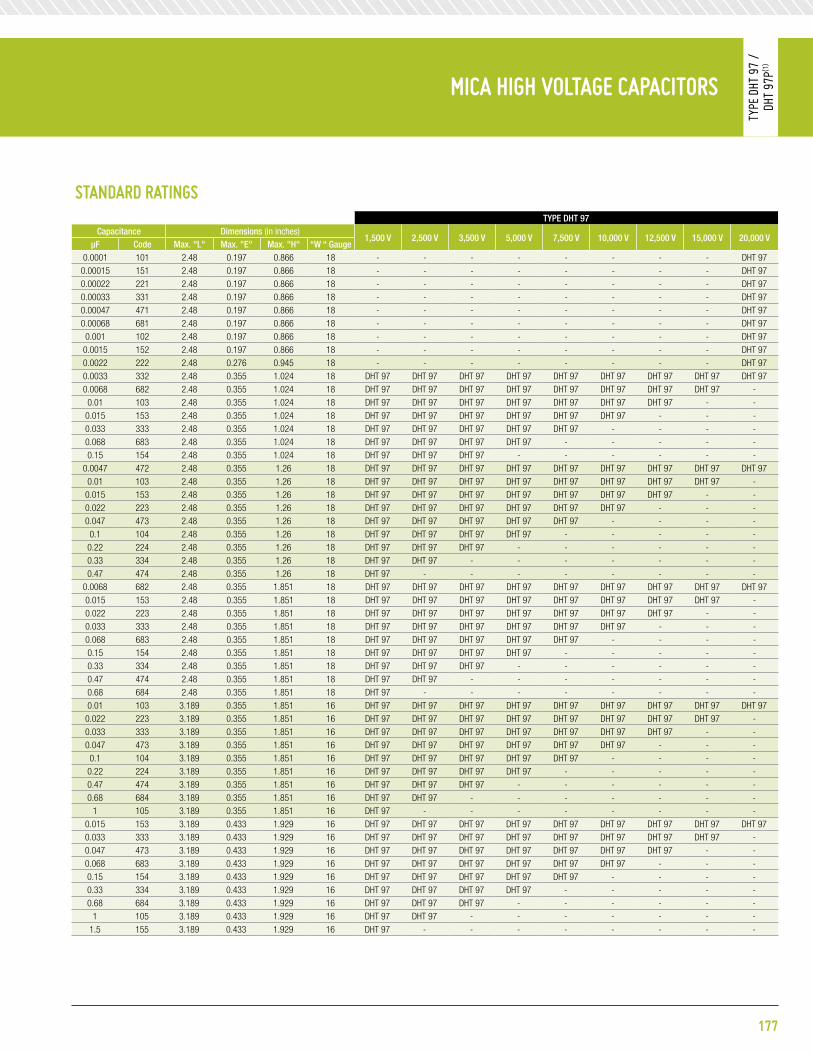
177
Wrap-and-Fill Metalized polypHenyleneSulFide FilM CapaCitorS
Type
832
p
MiCa HigH Voltage CapaCitorS
Type
DHT
97
/
DHT
97p(1
)
Standard ratingStype Dht 97
Capacitance Dimensions (in inches)1,500 V 2,500 V 3,500 V 5,000 V 7,500 V 10,000 V 12,500 V 15,000 V 20,000 V
μF Code max. "l" max. "e" max. "h" “w “ gauge0.0001 101 2.48 0.197 0.866 18 - - - - - - - - DHT 97
0.00015 151 2.48 0.197 0.866 18 - - - - - - - - DHT 970.00022 221 2.48 0.197 0.866 18 - - - - - - - - DHT 970.00033 331 2.48 0.197 0.866 18 - - - - - - - - DHT 970.00047 471 2.48 0.197 0.866 18 - - - - - - - - DHT 970.00068 681 2.48 0.197 0.866 18 - - - - - - - - DHT 970.001 102 2.48 0.197 0.866 18 - - - - - - - - DHT 97
0.0015 152 2.48 0.197 0.866 18 - - - - - - - - DHT 970.0022 222 2.48 0.276 0.945 18 - - - - - - - - DHT 970.0033 332 2.48 0.355 1.024 18 DHT 97 DHT 97 DHT 97 DHT 97 DHT 97 DHT 97 DHT 97 DHT 97 DHT 970.0068 682 2.48 0.355 1.024 18 DHT 97 DHT 97 DHT 97 DHT 97 DHT 97 DHT 97 DHT 97 DHT 97 -0.01 103 2.48 0.355 1.024 18 DHT 97 DHT 97 DHT 97 DHT 97 DHT 97 DHT 97 DHT 97 - -
0.015 153 2.48 0.355 1.024 18 DHT 97 DHT 97 DHT 97 DHT 97 DHT 97 DHT 97 - - -0.033 333 2.48 0.355 1.024 18 DHT 97 DHT 97 DHT 97 DHT 97 DHT 97 - - - -0.068 683 2.48 0.355 1.024 18 DHT 97 DHT 97 DHT 97 DHT 97 - - - - -0.15 154 2.48 0.355 1.024 18 DHT 97 DHT 97 DHT 97 - - - - - -
0.0047 472 2.48 0.355 1.26 18 DHT 97 DHT 97 DHT 97 DHT 97 DHT 97 DHT 97 DHT 97 DHT 97 DHT 970.01 103 2.48 0.355 1.26 18 DHT 97 DHT 97 DHT 97 DHT 97 DHT 97 DHT 97 DHT 97 DHT 97 -
0.015 153 2.48 0.355 1.26 18 DHT 97 DHT 97 DHT 97 DHT 97 DHT 97 DHT 97 DHT 97 - -0.022 223 2.48 0.355 1.26 18 DHT 97 DHT 97 DHT 97 DHT 97 DHT 97 DHT 97 - - -0.047 473 2.48 0.355 1.26 18 DHT 97 DHT 97 DHT 97 DHT 97 DHT 97 - - - -0.1 104 2.48 0.355 1.26 18 DHT 97 DHT 97 DHT 97 DHT 97 - - - - -
0.22 224 2.48 0.355 1.26 18 DHT 97 DHT 97 DHT 97 - - - - - -0.33 334 2.48 0.355 1.26 18 DHT 97 DHT 97 - - - - - - -0.47 474 2.48 0.355 1.26 18 DHT 97 - - - - - - - -
0.0068 682 2.48 0.355 1.851 18 DHT 97 DHT 97 DHT 97 DHT 97 DHT 97 DHT 97 DHT 97 DHT 97 DHT 970.015 153 2.48 0.355 1.851 18 DHT 97 DHT 97 DHT 97 DHT 97 DHT 97 DHT 97 DHT 97 DHT 97 -0.022 223 2.48 0.355 1.851 18 DHT 97 DHT 97 DHT 97 DHT 97 DHT 97 DHT 97 DHT 97 - -0.033 333 2.48 0.355 1.851 18 DHT 97 DHT 97 DHT 97 DHT 97 DHT 97 DHT 97 - - -0.068 683 2.48 0.355 1.851 18 DHT 97 DHT 97 DHT 97 DHT 97 DHT 97 - - - -0.15 154 2.48 0.355 1.851 18 DHT 97 DHT 97 DHT 97 DHT 97 - - - - -0.33 334 2.48 0.355 1.851 18 DHT 97 DHT 97 DHT 97 - - - - - -0.47 474 2.48 0.355 1.851 18 DHT 97 DHT 97 - - - - - - -0.68 684 2.48 0.355 1.851 18 DHT 97 - - - - - - - -0.01 103 3.189 0.355 1.851 16 DHT 97 DHT 97 DHT 97 DHT 97 DHT 97 DHT 97 DHT 97 DHT 97 DHT 97
0.022 223 3.189 0.355 1.851 16 DHT 97 DHT 97 DHT 97 DHT 97 DHT 97 DHT 97 DHT 97 DHT 97 -0.033 333 3.189 0.355 1.851 16 DHT 97 DHT 97 DHT 97 DHT 97 DHT 97 DHT 97 DHT 97 - -0.047 473 3.189 0.355 1.851 16 DHT 97 DHT 97 DHT 97 DHT 97 DHT 97 DHT 97 - - -0.1 104 3.189 0.355 1.851 16 DHT 97 DHT 97 DHT 97 DHT 97 DHT 97 - - - -
0.22 224 3.189 0.355 1.851 16 DHT 97 DHT 97 DHT 97 DHT 97 - - - - -0.47 474 3.189 0.355 1.851 16 DHT 97 DHT 97 DHT 97 - - - - - -0.68 684 3.189 0.355 1.851 16 DHT 97 DHT 97 - - - - - - -
1 105 3.189 0.355 1.851 16 DHT 97 - - - - - - - -0.015 153 3.189 0.433 1.929 16 DHT 97 DHT 97 DHT 97 DHT 97 DHT 97 DHT 97 DHT 97 DHT 97 DHT 970.033 333 3.189 0.433 1.929 16 DHT 97 DHT 97 DHT 97 DHT 97 DHT 97 DHT 97 DHT 97 DHT 97 -0.047 473 3.189 0.433 1.929 16 DHT 97 DHT 97 DHT 97 DHT 97 DHT 97 DHT 97 DHT 97 - -0.068 683 3.189 0.433 1.929 16 DHT 97 DHT 97 DHT 97 DHT 97 DHT 97 DHT 97 - - -0.15 154 3.189 0.433 1.929 16 DHT 97 DHT 97 DHT 97 DHT 97 DHT 97 - - - -0.33 334 3.189 0.433 1.929 16 DHT 97 DHT 97 DHT 97 DHT 97 - - - - -0.68 684 3.189 0.433 1.929 16 DHT 97 DHT 97 DHT 97 - - - - - -
1 105 3.189 0.433 1.929 16 DHT 97 DHT 97 - - - - - - -1.5 155 3.189 0.433 1.929 16 DHT 97 - - - - - - - -

Standard ratingStype Dht 97
Capacitance Dimensions (in inches)1,500 V 2,500 V 3,500 V 5,000 V 7,500 V 10,000 V 12,500 V 15,000 V 20,000 V
μF Code max. "l" max. "e" max. "h" “w “ gauge0.022 223 4.213 0.433 1.929 16 DHT 97 DHT 97 DHT 97 DHT 97 DHT 97 DHT 97 DHT 97 DHT 97 DHT 970.047 473 4.213 0.433 1.929 16 DHT 97 DHT 97 DHT 97 DHT 97 DHT 97 DHT 97 DHT 97 DHT 97 -0.068 683 4.213 0.433 1.929 16 DHT 97 DHT 97 DHT 97 DHT 97 DHT 97 DHT 97 DHT 97 - -0.1 104 4.213 0.433 1.929 16 DHT 97 DHT 97 DHT 97 DHT 97 DHT 97 DHT 97 - - -
0.22 224 4.213 0.433 1.929 16 DHT 97 DHT 97 DHT 97 DHT 97 DHT 97 - - - -0.47 474 4.213 0.433 1.929 16 DHT 97 DHT 97 DHT 97 DHT 97 - - - - -
1 105 4.213 0.433 1.929 16 DHT 97 DHT 97 DHT 97 - - - - - -1.5 155 4.213 0.433 1.929 16 DHT 97 DHT 97 - - - - - - -2.2 225 4.213 0.433 1.929 16 DHT 97 - - - - - - - -
0.033 333 4.213 0.63 2.047 16 DHT 97 DHT 97 DHT 97 DHT 97 DHT 97 DHT 97 DHT 97 DHT 97 DHT 970.068 68 4.213 0.63 2.047 16 DHT 97 DHT 97 DHT 97 DHT 97 DHT 97 DHT 97 DHT 97 DHT 97 -0.1 104 4.213 0.63 2.047 16 DHT 97 DHT 97 DHT 97 DHT 97 DHT 97 DHT 97 DHT 97 - -
0.15 154 4.213 0.63 2.047 16 DHT 97 DHT 97 DHT 97 DHT 97 DHT 97 DHT 97 - - -0.33 334 4.213 0.63 2.047 16 DHT 97 DHT 97 DHT 97 DHT 97 DHT 97 - - - -0.68 684 4.213 0.63 2.047 16 DHT 97 DHT 97 DHT 97 DHT 97 - - - - -1.5 155 4.213 0.63 2.047 16 DHT 97 DHT 97 DHT 97 - - - - - -
Standard ratingStype Dht 97p(1)
Capacitance Dimensions (in inches)1,500 V 2,500 V 3,500 V 5,000 V 7,500 V 10,000 V 12,500 V 15,000 V 20,000 V
μF Code max. "l" max. "e" max. "h" “w “ gauge0.0033 332 1.024 0.197 0.512 18 DHT 97P(1) DHT 97P(1) DHT 97P(1) DHT 97P(1) - - - - -0.0068 682 1.024 0.197 0.512 18 DHT 97P(1) DHT 97P(1) DHT 97P(1) - - - - - -0.015 153 1.024 0.197 0.512 18 DHT 97P(1) DHT 97P(1) - - - - - - -0.022 223 1.024 0.197 0.512 18 DHT 97P(1) - - - - - - - -0.001 102 1.418 0.177 0.512 18 DHT 97P(1) DHT 97P(1) DHT 97P(1) DHT 97P(1) DHT 97P(1) DHT 97P(1) DHT 97P(1) - -0.0022 222 1.418 0.177 0.512 18 DHT 97P(1) DHT 97P(1) DHT 97P(1) DHT 97P(1) DHT 97P(1) - - - -0.0047 472 1.418 0.177 0.512 18 DHT 97P(1) DHT 97P(1) DHT 97P(1) DHT 97P(1) - - - - -0.01 103 1.418 0.177 0.512 18 DHT 97P(1) DHT 97P(1) DHT 97P(1) - - - - - -
0.022 223 1.418 0.177 0.512 18 DHT 97P(1) DHT 97P(1) - - - - - - -0.033 333 1.418 0.177 0.512 18 DHT 97P(1) - - - - - - - -
0.0015 152 1.418 0.177 0.512 18 DHT 97P(1) DHT 97P(1) DHT 97P(1) DHT 97P(1) DHT 97P(1) DHT 97P(1) - - -0.0033 332 1.418 0.177 0.512 18 DHT 97P(1) DHT 97P(1) DHT 97P(1) DHT 97P(1) DHT 97P(1) - - - -0.0068 682 1.418 0.177 0.512 18 DHT 97P(1) DHT 97P(1) DHT 97P(1) DHT 97P(1) - - - - -0.015 153 1.418 0.177 0.512 18 DHT 97P(1) DHT 97P(1) DHT 97P(1) - - - - - -0.033 333 1.418 0.177 0.512 18 DHT 97P(1) DHT 97P(1) - - - - - - -0.047 473 1.418 0.177 0.512 18 DHT 97P(1) - - - - - - - -0.001 102 1.418 0.276 0.512 18 DHT 97P(1) DHT 97P(1) DHT 97P(1) DHT 97P(1) DHT 97P(1) DHT 97P(1) DHT 97P(1) DHT 97P(1) -0.0015 152 1.418 0.276 0.512 18 DHT 97P(1) DHT 97P(1) DHT 97P(1) DHT 97P(1) DHT 97P(1) DHT 97P(1) DHT 97P(1) - -0.0022 222 1.418 0.276 0.512 18 DHT 97P(1) DHT 97P(1) DHT 97P(1) DHT 97P(1) DHT 97P(1) DHT 97P(1) - - -0.0047 472 1.418 0.276 0.512 18 DHT 97P(1) DHT 97P(1) DHT 97P(1) DHT 97P(1) DHT 97P(1) - - - -0.01 103 1.418 0.276 0.512 18 DHT 97P(1) DHT 97P(1) DHT 97P(1) DHT 97P(1) - - - - -
0.022 223 1.418 0.276 0.512 18 DHT 97P(1) DHT 97P(1) DHT 97P(1) - - - - - -0.047 473 1.418 0.276 0.512 18 DHT 97P(1) DHT 97P(1) - - - - - - -0.068 673 1.418 0.276 0.512 18 DHT 97P(1) - - - - - - - -
note: P(1) Premolded Capacitor for Dielectric Fluid use or Encapsulation.
MiCa HigH Voltage CapaCitorS
Type
DHT
97
/
DHT
97p(1
)
178

179
Wrap-and-Fill Metalized polypHenyleneSulFide FilM CapaCitorS
Type
832
p
MiCa HigH Voltage CapaCitorS
Type
DHT
97
/
DHT
97p(1
)
Standard ratingStype Dht 97p(1)
Capacitance Dimensions (in inches)1,500 V 2,500 V 3,500 V 5,000 V 7,500 V 10,000 V 12,500 V 15,000 V 20,000 V
μF Code max. "l" max. "e" max. "h" “w “ gauge0.0015 152 1.418 0.276 0.669 18 DHT 97P(1) DHT 97P(1) DHT 97P(1) DHT 97P(1) DHT 97P(1) DHT 97P(1) DHT 97P(1) DHT 97P(1) -0.0022 222 1.418 0.276 0.669 18 DHT 97P(1) DHT 97P(1) DHT 97P(1) DHT 97P(1) DHT 97P(1) DHT 97P(1) DHT 97P(1) - -0.0033 332 1.418 0.276 0.669 18 DHT 97P(1) DHT 97P(1) DHT 97P(1) DHT 97P(1) DHT 97P(1) DHT 97P(1) - - -0.0068 682 1.418 0.276 0.669 18 DHT 97P(1) DHT 97P(1) DHT 97P(1) DHT 97P(1) DHT 97P(1) - - - -0.015 153 1.418 0.276 0.669 18 DHT 97P(1) DHT 97P(1) DHT 97P(1) DHT 97P(1) - - - - -0.033 333 1.418 0.276 0.669 18 DHT 97P(1) DHT 97P(1) DHT 97P(1) - - - - - -0.068 683 1.418 0.276 0.669 18 DHT 97P(1) DHT 97P(1) - - - - - - -0.1 104 1.418 0.276 0.669 18 DHT 97P(1) - - - - - - - -
0.0022 222 1.418 0.276 0.984 18 DHT 97P(1) DHT 97P(1) DHT 97P(1) DHT 97P(1) DHT 97P(1) DHT 97P(1) DHT 97P(1) DHT 97P(1) -0.0033 332 1.418 0.276 0.984 18 DHT 97P(1) DHT 97P(1) DHT 97P(1) DHT 97P(1) DHT 97P(1) DHT 97P(1) DHT 97P(1) - -0.0047 472 1.418 0.276 0.984 18 DHT 97P(1) DHT 97P(1) DHT 97P(1) DHT 97P(1) DHT 97P(1) DHT 97P(1) - - -0.01 103 1.418 0.276 0.984 18 DHT 97P(1) DHT 97P(1) DHT 97P(1) DHT 97P(1) DHT 97P(1) - - - -
0.022 223 1.418 0.276 0.984 18 DHT 97P(1) DHT 97P(1) DHT 97P(1) DHT 97P(1) - - - - -0.047 473 1.418 0.276 0.984 18 DHT 97P(1) DHT 97P(1) DHT 97P(1) - - - - - -0.1 104 1.418 0.276 0.984 18 DHT 97P(1) DHT 97P(1) - - - - - - -
0.15 155 1.418 0.276 0.984 18 DHT 97P(1) - - - - - - - -0.0033 332 1.418 0.355 1.22 18 DHT 97P(1) DHT 97P(1) DHT 97P(1) DHT 97P(1) DHT 97P(1) DHT 97P(1) DHT 97P(1) DHT 97P(1) -0.0047 472 1.418 0.355 1.22 18 DHT 97P(1) DHT 97P(1) DHT 97P(1) DHT 97P(1) DHT 97P(1) DHT 97P(1) DHT 97P(1) - -0.0068 682 1.418 0.355 1.22 18 DHT 97P(1) DHT 97P(1) DHT 97P(1) DHT 97P(1) DHT 97P(1) DHT 97P(1) - - -0.015 153 1.418 0.355 1.22 18 DHT 97P(1) DHT 97P(1) DHT 97P(1) DHT 97P(1) DHT 97P(1) - - - -0.033 333 1.418 0.355 1.22 18 DHT 97P(1) DHT 97P(1) DHT 97P(1) DHT 97P(1) - - - - -0.068 683 1.418 0.355 1.22 18 DHT 97P(1) DHT 97P(1) DHT 97P(1) - - - - - -0.15 154 1.418 0.355 1.22 18 DHT 97P(1) DHT 97P(1) - - - - - - -0.22 224 1.418 0.355 1.22 18 DHT 97P(1) - - - - - - - -
0.0047 472 1.418 0.355 1.614 18 DHT 97P(1) DHT 97P(1) DHT 97P(1) DHT 97P(1) DHT 97P(1) DHT 97P(1) DHT 97P(1) DHT 97P(1) -0.0068 682 1.418 0.355 1.641 18 DHT 97P(1) DHT 97P(1) DHT 97P(1) DHT 97P(1) DHT 97P(1) DHT 97P(1) DHT 97P(1) - -0.01 103 1.418 0.355 1.614 18 DHT 97P(1) DHT 97P(1) DHT 97P(1) DHT 97P(1) DHT 97P(1) DHT 97P(1) - - -0.022 223 1.418 0.355 1.614 18 DHT 97P(1) DHT 97P(1) DHT 97P(1) DHT 97P(1) DHT 97P(1) - - - -0.047 473 1.418 0.355 1.614 18 DHT 97P(1) DHT 97P(1) DHT 97P(1) DHT 97P(1) - - - - -0.1 104 1.418 0.355 1.614 18 DHT 97P(1) DHT 97P(1) DHT 97P(1) - - - - - -
0.22 224 1.418 0.355 1.614 18 DHT 97P(1) DHT 97P(1) - - - - - - -0.33 334 1.418 0.355 1.614 18 DHT 97P(1) - - - - - - - -
0.0001 101 2.441 0.197 0.827 18 - - - - - - - - DHT 97P(1)
0.00015 151 2.441 0.197 0.827 18 - - - - - - - - DHT 97P(1)
0.00022 221 2.441 0.197 0.827 18 - - - - - - - - DHT 97P(1)
0.00033 331 2.441 0.197 0.827 18 - - - - - - - - DHT 97P(1)
0.00047 471 2.441 0.197 0.827 18 - - - - - - - - DHT 97P(1)
0.00068 681 2.441 0.197 0.827 18 - - - - - - - - DHT 97P(1)
0.001 102 2.441 0.197 0.827 18 - - - - - - - - DHT 97P(1)
0.0015 152 2.441 0.197 0.827 18 - - - - - - - - DHT 97P(1)
0.0022 222 2.441 0.276 0.906 18 DHT 97P(1) DHT 97P(1) DHT 97P(1) DHT 97P(1) DHT 97P(1) DHT 97P(1) DHT 97P(1) DHT 97P(1) DHT 97P(1)
0.0033 332 2.441 0.355 0.984 18 DHT 97P(1) DHT 97P(1) DHT 97P(1) DHT 97P(1) DHT 97P(1) DHT 97P(1) DHT 97P(1) DHT 97P(1) DHT 97P(1)
0.0068 682 2.441 0.355 0.984 18 DHT 97P(1) DHT 97P(1) DHT 97P(1) DHT 97P(1) DHT 97P(1) DHT 97P(1) DHT 97P(1) DHT 97P(1) -0.01 103 2.441 0.355 0.984 18 DHT 97P(1) DHT 97P(1) DHT 97P(1) DHT 97P(1) DHT 97P(1) DHT 97P(1) DHT 97P(1) - -
0.015 153 2.441 0.355 0.984 18 DHT 97P(1) DHT 97P(1) DHT 97P(1) DHT 97P(1) DHT 97P(1) DHT 97P(1) - - -0.033 333 2.441 0.355 0.984 18 DHT 97P(1) DHT 97P(1) DHT 97P(1) DHT 97P(1) DHT 97P(1) - - - -0.068 683 2.441 0.355 0.984 18 DHT 97P(1) DHT 97P(1) DHT 97P(1) DHT 97P(1) - - - - -0.15 154 2.441 0.355 0.984 18 DHT 97P(1) DHT 97P(1) DHT 97P(1) - - - - - -
note: P(1) Premolded Capacitor for Dielectric Fluid use or Encapsulation.

Standard ratingStype Dht 97p(1)
Capacitance Dimensions (in inches)1,500 V 2,500 V 3,500 V 5,000 V 7,500 V 10,000 V 12,500 V 15,000 V 20,000 V
μF Code max. "l" max. "e" max. "h" “w “ gauge0.0047 472 2.441 0.355 1.22 18 DHT 97P(1) DHT 97P(1) DHT 97P(1) DHT 97P(1) DHT 97P(1) DHT 97P(1) DHT 97P(1) DHT 97P(1) DHT 97P(1)
0.01 103 2.441 0.355 1.22 18 DHT 97P(1) DHT 97P(1) DHT 97P(1) DHT 97P(1) DHT 97P(1) DHT 97P(1) DHT 97P(1) DHT 97P(1) -0.015 153 2.441 0.355 1.22 18 DHT 97P(1) DHT 97P(1) DHT 97P(1) DHT 97P(1) DHT 97P(1) DHT 97P(1) DHT 97P(1) - -0.022 223 2.441 0.355 1.22 18 DHT 97P(1) DHT 97P(1) DHT 97P(1) DHT 97P(1) DHT 97P(1) DHT 97P(1) - - -0.047 473 2.441 0.355 1.22 18 DHT 97P(1) DHT 97P(1) DHT 97P(1) DHT 97P(1) DHT 97P(1) - - - -0.1 104 2.441 0.355 1.22 18 DHT 97P(1) DHT 97P(1) DHT 97P(1) DHT 97P(1) - - - - -
0.22 224 2.441 0.355 1.22 18 DHT 97P(1) DHT 97P(1) DHT 97P(1) - - - - - -0.33 334 2.441 0.355 1.22 18 DHT 97P(1) DHT 97P(1) - - - - - - -0.47 474 2.441 0.355 1.22 18 DHT 97P(1) - - - - - - - -
0.0068 682 2.441 0.355 1.811 18 DHT 97P(1) DHT 97P(1) DHT 97P(1) DHT 97P(1) DHT 97P(1) DHT 97P(1) DHT 97P(1) DHT 97P(1) DHT 97P(1)
0.015 153 2.441 0.355 1.811 18 DHT 97P(1) DHT 97P(1) DHT 97P(1) DHT 97P(1) DHT 97P(1) DHT 97P(1) DHT 97P(1) DHT 97P(1) -0.022 223 2.441 0.355 1.811 18 DHT 97P(1) DHT 97P(1) DHT 97P(1) DHT 97P(1) DHT 97P(1) DHT 97P(1) DHT 97P(1) - -0.033 333 2.441 0.355 1.811 18 DHT 97P(1) DHT 97P(1) DHT 97P(1) DHT 97P(1) DHT 97P(1) DHT 97P(1) - - -0.068 683 2.441 0.355 1.811 18 DHT 97P(1) DHT 97P(1) DHT 97P(1) DHT 97P(1) DHT 97P(1) - - - -0.15 154 2.441 0.355 1.811 18 DHT 97P(1) DHT 97P(1) DHT 97P(1) DHT 97P(1) - - - - -0.33 334 2.441 0.355 1.811 18 DHT 97P(1) DHT 97P(1) DHT 97P(1) - - - - - -0.47 474 2.441 0.355 1.811 18 DHT 97P(1) DHT 97P(1) - - - - - - -0.68 684 2.441 0.355 1.811 18 DHT 97P(1) - - - - - - - -0.01 103 3.15 0.355 1.811 16 DHT 97P(1) DHT 97P(1) DHT 97P(1) DHT 97P(1) DHT 97P(1) DHT 97P(1) DHT 97P(1) DHT 97P(1) DHT 97P(1)
0.022 223 3.15 0.355 1.811 16 DHT 97P(1) DHT 97P(1) DHT 97P(1) DHT 97P(1) DHT 97P(1) DHT 97P(1) DHT 97P(1) DHT 97P(1) -0.033 333 3.15 0.355 1.811 16 DHT 97P(1) DHT 97P(1) DHT 97P(1) DHT 97P(1) DHT 97P(1) DHT 97P(1) DHT 97P(1) - -0.047 473 3.15 0.355 1.811 16 DHT 97P(1) DHT 97P(1) DHT 97P(1) DHT 97P(1) DHT 97P(1) DHT 97P(1) - - -0.1 104 3.15 0.355 1.811 16 DHT 97P(1) DHT 97P(1) DHT 97P(1) DHT 97P(1) DHT 97P(1) - - - -0.22 224 3.15 0.355 1.811 16 DHT 97P(1) DHT 97P(1) DHT 97P(1) DHT 97P(1) - - - - -0.47 474 3.15 0.355 1.811 16 DHT 97P(1) DHT 97P(1) DHT 97P(1) - - - - - -0.68 684 3.15 0.355 1.811 16 DHT 97P(1) DHT 97P(1) - - - - - - -
1 105 3.15 0.355 1.811 16 DHT 97P(1) - - - - - - - -0.015 153 3.15 0.433 1.89 16 DHT 97P(1) DHT 97P(1) DHT 97P(1) DHT 97P(1) DHT 97P(1) DHT 97P(1) DHT 97P(1) DHT 97P(1) DHT 97P(1)
0.033 333 3.15 0.433 1.89 16 DHT 97P(1) DHT 97P(1) DHT 97P(1) DHT 97P(1) DHT 97P(1) DHT 97P(1) DHT 97P(1) DHT 97P(1) -0.047 473 3.15 0.433 1.89 16 DHT 97P(1) DHT 97P(1) DHT 97P(1) DHT 97P(1) DHT 97P(1) DHT 97P(1) DHT 97P(1) - -0.068 683 3.15 0.433 1.89 16 DHT 97P(1) DHT 97P(1) DHT 97P(1) DHT 97P(1) DHT 97P(1) DHT 97P(1) - - -0.15 154 3.15 0.433 1.89 16 DHT 97P(1) DHT 97P(1) DHT 97P(1) DHT 97P(1) DHT 97P(1) - - - -0.33 334 3.15 0.433 1.89 16 DHT 97P(1) DHT 97P(1) DHT 97P(1) DHT 97P(1) - - - - -0.68 684 3.15 0.433 1.89 16 DHT 97P(1) DHT 97P(1) DHT 97P(1) - - - - - -
1 105 3.15 0.433 1.89 16 DHT 97P(1) DHT 97P(1) - - - - - - -1.5 155 3.15 0.433 1.89 16 DHT 97P(1) - - - - - - - -
0.022 223 4.173 0.433 1.89 16 DHT 97P(1) DHT 97P(1) DHT 97P(1) DHT 97P(1) DHT 97P(1) DHT 97P(1) DHT 97P(1) DHT 97P(1) DHT 97P(1)
0.047 473 4.173 0.433 1.89 16 DHT 97P(1) DHT 97P(1) DHT 97P(1) DHT 97P(1) DHT 97P(1) DHT 97P(1) DHT 97P(1) DHT 97P(1) -0.068 683 4.173 0.433 1.89 16 DHT 97P(1) DHT 97P(1) DHT 97P(1) DHT 97P(1) DHT 97P(1) DHT 97P(1) DHT 97P(1) - -0.1 104 4.173 0.433 1.89 16 DHT 97P(1) DHT 97P(1) DHT 97P(1) DHT 97P(1) DHT 97P(1) DHT 97P(1) - - -0.22 224 4.173 0.433 1.89 16 DHT 97P(1) DHT 97P(1) DHT 97P(1) DHT 97P(1) DHT 97P(1) - - - -0.47 474 4.173 0.433 1.89 16 DHT 97P(1) DHT 97P(1) DHT 97P(1) DHT 97P(1) - - - - -
1 105 4.173 0.433 1.89 16 DHT 97P(1) DHT 97P(1) DHT 97P(1) - - - - - -1.5 155 4.173 0.433 1.89 16 DHT 97P(1) DHT 97P(1) - - - - - - -2.2 225 4.173 0.433 1.89 16 DHT 97P(1) - - - - - - - -
0.033 333 4.173 0.591 2.008 16 DHT 97P(1) DHT 97P(1) DHT 97P(1) DHT 97P(1) DHT 97P(1) DHT 97P(1) DHT 97P(1) DHT 97P(1) DHT 97P(1)
0.068 68 4.173 0.591 2.008 16 DHT 97P(1) DHT 97P(1) DHT 97P(1) DHT 97P(1) DHT 97P(1) DHT 97P(1) DHT 97P(1) DHT 97P(1) -0.1 104 4.173 0.591 2.008 16 DHT 97P(1) DHT 97P(1) DHT 97P(1) DHT 97P(1) DHT 97P(1) DHT 97P(1) DHT 97P(1) - -
0.15 154 4.173 0.591 2.008 16 DHT 97P(1) DHT 97P(1) DHT 97P(1) DHT 97P(1) DHT 97P(1) DHT 97P(1) - - -0.33 334 4.173 0.591 2.008 16 DHT 97P(1) DHT 97P(1) DHT 97P(1) DHT 97P(1) DHT 97P(1) - - - -0.68 684 4.173 0.591 2.008 16 DHT 97P(1) DHT 97P(1) DHT 97P(1) DHT 97P(1) - - - - -1.5 155 4.173 0.591 2.008 16 DHT 97P(1) DHT 97P(1) DHT 97P(1) - - - - - -
note: P(1) Premolded Capacitor for Dielectric Fluid use or Encapsulation.
MiCa HigH Voltage CapaCitorS
Type
DHT
97
/
DHT
97p(1
)
180

noteS
181

182
noteS


1221 North US Highway 17-92Longwood, Florida 32750T 407 695-6562 • F 407 695-6889www.dearbornelectronics.com
FILM & MICA CAPACITORS
www.dearbornelectronics.com
FILM & MICA CAPACITORS