POWER CAPACITORS RELATED EQUIPMENT
45
POWER CAPACITORS RELATED EQUIPMENT SE-304-B
-
Upload
khangminh22 -
Category
Documents
-
view
0 -
download
0
Transcript of POWER CAPACITORS RELATED EQUIPMENT

POWER CAPACITORSRELATED EQUIPMENT
SE-304-B

1 HIGH VOLTAGE POWER CAPACITOR EQUIPMENT (Oil Filled & Self-cooled)
CONTENTS
4
5
6
8
10
12
13
14
15
16
17
19
21
22
23
24
25
26
31
32
40
41
42
43
33
34
35
38
18
2 HIGH VOLTAGE POWER CAPACITOR EQUIPMENT (DRY)
3 LOW VOLTAGE POWER CAPACITOR EQUIPMENTType N2 (200V) & E(200V, 400V) Low Voltage Power Capacitors
Plastic Film Capacitors (ETHY-CON)
Water Cooled Capacitors
Type RG-2 220V Low Voltage Power Capacitors (for L=6%) Combined Output 10-50kvar
Type RG-2 440V Low Voltage Power Capacitors (for L=6%) Combined Output 10-100kvar
Type GFC-5 Gas Filled 220V Low Voltage Power Capacitors (for L=6%) Combined Output 10-50kvar
Type GFC-5 Gas Filled 440V Low Voltage Power Capacitors (for L=6%) Combined Output 20-100kvar
Type DR-1 Series Reactors (for L=6%, I5=55%) Combined Output 10-300kvar
Type GFC-5 Gas Filled High Voltage Capacitors (for L=6%) Combined Output 10-300kvar
Type LR-MB Series Reactors (for L=6%, I5=55%) Combined Output 10-1000kvar
Type GFC-5 Gas Filled High Voltage Capacitors (for L=13%) Combined Output 10-300kvar
Type LR-MB Series Reactors (for L=13%, I5=35%) Combined Output 10-500kvar
Type DCM-B Power Capacitor Discharge Coils
Protection of Gas Filled High Voltage Capacitors & Reactors
Type LV-6 High Voltage Capacitors (for L=6%) Combined Output 10-100kvar
Type LV-6 High Voltage Capacitors (for L=6%) Combined Output 150-500kvar
Type LR-3 Series Reactors (for L=6%, I5=55%) Combined Output 10-1000kvar
Type LV-6 High Voltage Capacitors (for L=13%) Combined Output 10-500kvar
Type LR-3 Series Reactors (for L=13%, I5=35%) Combined Output 10-500kvar
Protection of High Voltage Capacitors & Reactors
Type LV-6 Capacitors Banks (Double Star Connected) (for L=6%) Combined Output 200-300kvar
Type FHZ High Voltage Capacitors (for L=6%) Combined Output 1000-3000kvar
Type Q-PAC-1B High Voltage Capacitor Equipment (for L=6%, I5=55%) Combined Output 100-1000kvar
Type Q-PAC-2B High Voltage Capacitor Equipment (for L=6%, I5=55%) Combined Output 100-1000kvar
Type Q-PAC-2B High Voltage Capacitor Equipment Coupled with Duct (for L=6%, I5=55%) Combined Output 100-1000kvar
Type HA-PAC High Voltage Capacitor Equipment with Automatic Capacitor Control (for L=6%, I5=55%) Combined Output 200-600kvar
4 SURGE ABSORBING CAPACITORS & GROUNDING CAPACITORS
5 HIGH FREQUENCY CAPACITORS
Type SQ-S4
Type Q-AUTOMAT III
6 AUTOMATIC CAPACITOR CONTROLLERS
36
37
Oil-less V-PAC for Installation in Panels (with L=6%, I5=55%)
Free Standing Enclosed V-PAC II (with L=6%, I5=55%)
TYPE LV-6 HIGH VOLTAGE POWER CAPACITORS & REACTORS
2
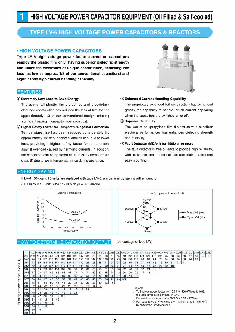
HIGH VOLTAGE POWER CAPACITOR EQUIPMENT (Oil Filled & Self-cooled)1
• HIGH VOLTAGE POWER CAPACITORSType LV-6 high voltage power factor correction capacitors
employ the plastic film only having superior dielectric strength
and utilize the electrodes of unique construction, achieving low
loss (as low as approx. 1/3 of our conventional capacitors) and
significantly high current handling capability.
qq Extremely Low Loss to Save Energy
The use of all plastic film dielectrics and proprietary
electrode construction has reduced the loss of film itself to
approximately 1/3 of our conventional design, offering
significant saving in capacitor operation cost.
ww Higher Safety Factor for Temperature against Harmonics
Temperature rise has been reduced considerably (to
approximately 1/2 of our conventional design) due to lower
loss, providing a higher safety factor for temperature
against overload caused by harmonic currents. In addition,
the capacitors can be operated at up to 50°C (temperature
class B) due to lower temperature rise during operation.
FEATURESee Enhanced Current Handling Capability
The proprietary extended foil construction has enhanced
greatly the capability to handle inrush current appearing
when the capacitors are switched on or off.
rr Superior Reliability
The use of polypropylene film dielectrics with excellent
electrical performances has enhanced dielectric strength
and reliability.
tt Fault Detector (MDA-1) for 150kvar or more
The fault detector is free of leaks to provide high reliability,
with its simple construction to facilitate maintenance and
easy mounting.
If LV-4 100kvar x 10 units are replaced with type LV-6, annual energy saving will amount to
(60-20) W x 10 units x 24 hr x 365 days = 3,504kWhr.
ENERGY SAVING
70
60
50
40
30
20
-20 0 20 40 60 80 100
10
0
Loss
per
100
kvar
(W
)
Temp. (°C)
Loss vs. Temperature
Type LV-4
Type LV-6
10kvar
100kvar
30kvar
50kvar
200kvar
150kvar
60
40
20
0Type LV-6 (new)
Type LV-4 (old)
Loss Comparison LV-4 vs. LV-6
0.40.450.50.550.60.650.70.750.80.850.90.920.940.950.960.970.980.99
230198173152133117102
8875624843363329252014
1.0216183159138119103
88746148342822181511
6
0.99210177153132113
978167544228221612
95
0.98205173148127108
9277635037231811
84
0.97201168144123104
88735846331913
73.5
0.96197165140119101
84695542291610
3.6
0.95194161137116
97816652392612
6
0.94190158134112
947762493522
93.1
0.93187155130109
917459453219
6
0.92184152128106
887156432916
2.8
0.91182149125104
856954402714
0.9175142118
977862463319
7
0.875168136111
907155402613
0.85161129104
8365483319
6
0.825155123
987758422713
0.8149116
9271523620
6.5
0.775142110
8564462914
0.75135103
78573922
7
0.725128
9671503215
0.7121
89644324
8
0.675 0.65 0.625105
734827
8.5
11381563516
0.696644019
0.57588563110
0.55784621
0.525683611
0.55724
0.4754512
0.4532 17
0.425
Exampleq To improve power factor from 0.75 for 500kW load to 0.95,
the table gives a percentage of 55%.Required capacitor output = 500kW x 0.55 = 275kvar
w For loads rated at kVA, calculate in a manner to similar to q by converting kW=kVAxcosf.E
xist
ing
Pow
er F
acto
r (C
osf
1)
(percentage of load kW)HOW TO DETERMINE CAPACITOR OUTPUT
HIGH VOLTAGE POWER CAPACITOR EQUIPMENT (Oil Filled & Self-cooled)1
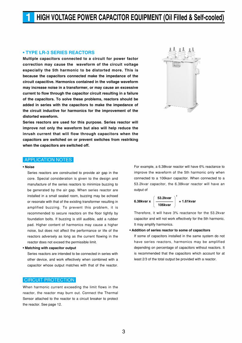
• TYPE LR-3 SERIES REACTORSMultiple capacitors connected to a circuit for power factor
correction may cause the waveform of the circuit voltage
especially the 5th harmonic to be distorted more. This is
because the capacitors connected make the impedance of the
circuit capacitive. Harmonics contained in the voltage waveform
may increase noise in a transformer, or may cause an excessive
current to flow through the capacitor circuit resulting in a failure
of the capacitors. To solve these problems, reactors should be
added in series with the capacitors to make the impedance of
the circuit inductive for harmonics for the improvement of the
distorted waveform.
Series reactors are used for this purpose. Series reactor will
improve not only the waveform but also will help reduce the
inrush current that will flow through capacitors when the
capacitors are switched on or prevent switches from restriking
when the capacitors are switched off.
• Noise
Series reactors are constructed to provide air gap in the
core. Special consideration is given to the design and
manufacture of the series reactors to minimize buzzing to
be generated by the air gap. When series reactor are
installed in a small sealed room, buzzing may be echoed
or resonate with that of the existing transformer resulting in
amplified buzzing. To prevent this problem, it is
recommended to secure reactors on the floor tightly by
foundation bolts. If buzzing is still audible, add a rubber
pad. Higher content of harmonics may cause a higher
noise, but does not affect the performance or life of the
reactors adversely as long as the current flowing in the
reactor does not exceed the permissible limit.
• Matching with capacitor output
Series reactors are intended to be connected in series with
other device, and work effectively when combined with a
capacitor whose output matches with that of the reactor.
APPLICATION NOTESFor example, a 6.38kvar reactor will have 6% reactance to
improve the waveform of the 5th harmonic only when
connected to a 106kavr capacitor. When connected to a
53.2kvar capacitor, the 6.38kvar reactor will have an
output of
Therefore, it will have 3% reactance for the 53.2kvar
capacitor and will not work effectively for the 5th harmonic.
It may amplify harmonics.
• Addition of series reactor to some of capacitors
If some of capacitors installed in the same system do not
have series reactors, harmonics may be amplified
depending on percentage of capacitors without reactors. It
is recommended that the capacitors which account for at
least 2/3 of the total output be provided with a reactor.
3
6.38kvar x = 1.61kvar53.2kvar
106kvar
2
When harmonic current exceeding the limit flows in the
reactor, the reactor may burn out. Connect the Thermal
Sensor attached to the reactor to a circuit breaker to protect
the reactor. See page 12.
CIRCUIT PROTECTION
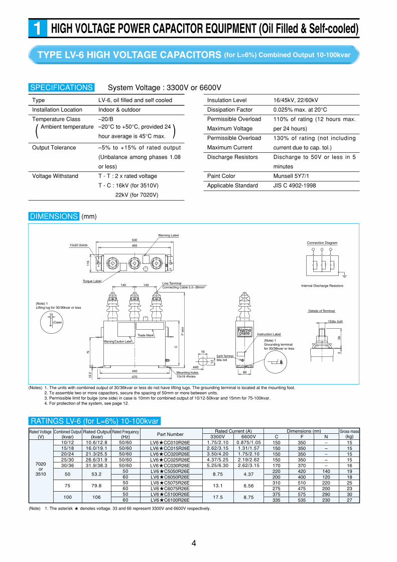
System Voltage : 3300V or 6600V
TYPE LV-6 HIGH VOLTAGE CAPACITORS (for L=6%) Combined Output 10-100kvar
4
HIGH VOLTAGE POWER CAPACITOR EQUIPMENT (Oil Filled & Self-cooled)1
Type LV-6, oil filled and self cooled
Installation Location Indoor & outdoor
Temperature Class –20/B
Output Tolerance –5% to +15% of rated output
(Unbalance among phases 1.08
or less)
Voltage Withstand T - T : 2 x rated voltage
T - C : 16kV (for 3510V)
22kV (for 7020V)
SPECIFICATIONS
Ambient temperature –20°C to +50°C, provided 24
hour average is 45°C max. )(
Insulation Level 16/45kV, 22/60kV
Dissipation Factor 0.025% max. at 20°C
110% of rating (12 hours max.
per 24 hours)
130% of rating (not including
current due to cap. tol.)
Discharge Resistors Discharge to 50V or less in 5
minutes
Paint Color Munsell 5Y7/1
Applicable Standard JIS C 4902-1998
DIMENSIONS (mm)
Details of Terminal
500
115
140 140
39
12dia. bolt
3
465
Mounting holes12x16 4holes
15x20 2slots
(Case)
(Note) 1Lifting lug for 30/36kvar or less
15
Trade Mark
Warning/Caution Label
Earth Terminal8dia. bolt
80
F M
AX
C
440
470t3.2
N
Instruction LabelNameplate
Warning Label
Torque LabelLine TerminalConnecting Cable 5.5~38mm2
(Note) 1Grounding terminalfor 30/36kvar or less
12
16
Connection Diagram
Internal Discharge Resistors
440
RATINGS LV-6 (for L=6%) 10-100kvar
LV6 CC010R26ELV6 CC015R26ELV6 CC020R26ELV6 CC025R26ELV6 CC030R26ELV6 C5050R26ELV6 C6050R26ELV6 C5075R26ELV6 C6075R26ELV6 C5100R26ELV6 C6100R26E
1515151516191825233027
Gross mass(kg)
Rated Voltage (V)
7020or
3510
Combined Output(kvar)10/1215/1820/2425/3030/36
10.6/12.816.0/19.121.3/25.526.6/31.931.9/38.3
50
75
100
53.2
79.8
106
3300V1.75/2.102.62/3.153.50/4.204.37/5.255.25/6.30
8.75
13.1
17.5
C150150150150170220200310275375335
F350350350350370420400510475575535
N–––––
140120220200290230
50/6050/6050/6050/6050/60
506050605060
Rated Frequency(Hz)
Rated Output(kvar)
Rated Current (A)Part Number
Dimensions (mm)6600V
0.875/1.051.31/1.571.75/2.102.19/2.622.62/3.15
4.37
6.56
8.75
(Note) 1. The asterisk denotes voltage. 33 and 66 represent 3300V and 6600V respectively.
(Notes) 1. The units with combined output of 30/36kvar or less do not have lifting lugs. The grounding terminal is located at the mounting foot.2. To assemble two or more capacitors, secure the spacing of 50mm or more between units.3. Permissible limit for bulge (one side) in case is 10mm for combined output of 10/12-50kvar and 15mm for 75-100kvar.4. For protection of the system, see page 12.
Permissible Overload
Maximum Voltage
Permissible Overload
Maximum Current
5
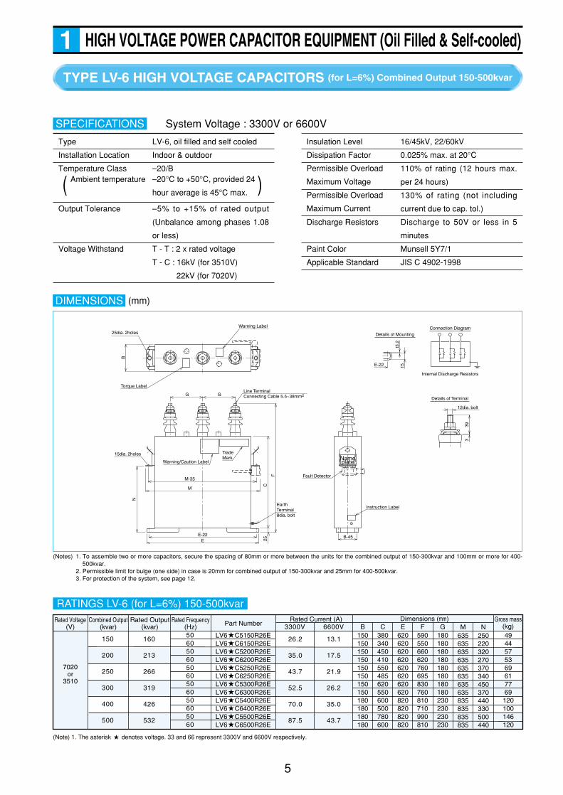
HIGH VOLTAGE POWER CAPACITOR EQUIPMENT (Oil Filled & Self-cooled)1TYPE LV-6 HIGH VOLTAGE CAPACITORS (for L=6%) Combined Output 150-500kvar
Type LV-6, oil filled and self cooled
Installation Location Indoor & outdoor
Temperature Class –20/B
Output Tolerance –5% to +15% of rated output
(Unbalance among phases 1.08
or less)
Voltage Withstand T - T : 2 x rated voltage
T - C : 16kV (for 3510V)
22kV (for 7020V)
SPECIFICATIONS
Ambient temperature –20°C to +50°C, provided 24
hour average is 45°C max. )(
Insulation Level 16/45kV, 22/60kV
Dissipation Factor 0.025% max. at 20°C
110% of rating (12 hours max.
per 24 hours)
130% of rating (not including
current due to cap. tol.)
Discharge Resistors Discharge to 50V or less in 5
minutes
Paint Color Munsell 5Y7/1
Applicable Standard JIS C 4902-1998
GG
15dia. 2holes
25dia. 2holes
Warning/Caution Label
Warning Label
12dia. bolt
39
15t3
.2
3
Connection DiagramDetails of Mounting
Internal Discharge Resistors
Details of Terminal
E-22
Torque Label
Instruction LabelEarth Terminal8dia. bolt
Fault Detector
Line TerminalConnecting Cable 5.5~38mm2
Trade Mark
M-35
M
E-22E
N
B
C25
F
B-45
Nameplate
RATINGS LV-6 (for L=6%) 150-500kvar
(Note) 1. The asterisk denotes voltage. 33 and 66 represent 3300V and 6600V respectively.
DIMENSIONS
LV6 C5150R26ELV6 C6150R26ELV6 C5200R26ELV6 C6200R26ELV6 C5250R26ELV6 C6250R26ELV6 C5300R26ELV6 C6300R26ELV6 C5400R26ELV6 C6400R26ELV6 C5500R26ELV6 C6500R26E
4944575369617769120100146120
BGross mass
(kg)Rated Voltage
(V)
7020or
3510
Combined Output(kvar)
150
200
250
300
400
500
160
213
266
319
426
532
3300V150150150150150150150150180180180180
C380340450410550485620550600500780600
E620620620620620620620620820820820820
F590550660620760695830760810710990810
G180180180180180180180180230230230230
506050605060506050605060
Rated Frequency(Hz)
Rated Output(kvar)
Rated Current (A)Part Number
Dimensions (mm)M
635635635635635635635635835835835835
N250220320270370340450370440330500440
6600V
13.1
17.5
21.9
26.2
35.0
43.7
26.2
35.0
43.7
52.5
70.0
87.5
System Voltage : 3300V or 6600V
(Notes) 1. To assemble two or more capacitors, secure the spacing of 80mm or more between the units for the combined output of 150-300kvar and 100mm or more for 400-500kvar.
2. Permissible limit for bulge (one side) in case is 20mm for combined output of 150-300kvar and 25mm for 400-500kvar.3. For protection of the system, see page 12.
Permissible Overload
Maximum Voltage
Permissible Overload
Maximum Current
(mm)
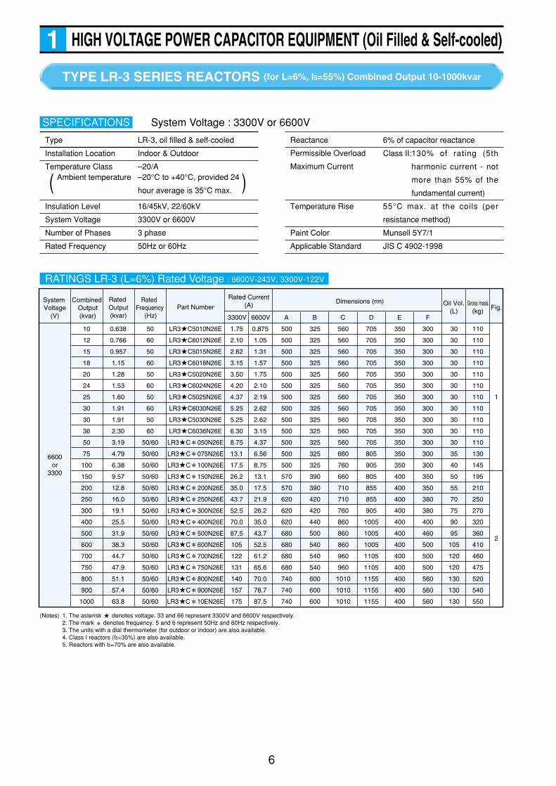
TYPE LR-3 SERIES REACTORS (for L=6%, I5=55%) Combined Output 10-1000kvar
6
HIGH VOLTAGE POWER CAPACITOR EQUIPMENT (Oil Filled & Self-cooled)1
Type LR-3, oil filled & self-cooled
Installation Location Indoor & Outdoor
Temperature Class –20/A
Insulation Level 16/45kV, 22/60kV
System Voltage 3300V or 6600V
Number of Phases 3 phase
Rated Frequency 50Hz or 60Hz
SPECIFICATIONS
Ambient temperature –20°C to +40°C, provided 24
hour average is 35°C max. )(
Reactance 6% of capacitor reactance
Class II:130% of rating (5th
harmonic current - not
more than 55% of the
fundamental current)
Temperature Rise 55°C max. at the coils (per
resistance method)
Paint Color Munsell 5Y7/1
Applicable Standard JIS C 4902-1998
System Voltage : 3300V or 6600V
RATINGS LR-3 (L=6%) Rated Voltage : 6600V-243V, 3300V-122V
System Voltage
(V)
6600or
3300
Combined Output(kvar)
10
12
15
18
20
24
25
30
30
36
50
75
100
150
200
250
300
400
500
600
700
750
800
900
1000
50
60
50
60
50
60
50
60
50
60
50/60
50/60
50/60
50/60
50/60
50/60
50/60
50/60
50/60
50/60
50/60
50/60
50/60
50/60
50/60
0.638
0.766
0.957
1.15
1.28
1.53
1.60
1.91
1.91
2.30
3.19
4.79
6.38
9.57
12.8
16.0
19.1
25.5
31.9
38.3
44.7
47.9
51.1
57.4
63.8
1.75
2.10
2.62
3.15
3.50
4.20
4.37
5.25
5.25
6.30
8.75
13.1
17.5
26.2
35.0
43.7
52.5
70.0
87.5
105
122
131
140
157
175
0.875
1.05
1.31
1.57
1.75
2.10
2.19
2.62
2.62
3.15
4.37
6.56
8.75
13.1
17.5
21.9
26.2
35.0
43.7
52.5
61.2
65.6
70.0
78.7
87.5
500
500
500
500
500
500
500
500
500
500
500
500
500
570
570
620
620
620
680
680
680
680
740
740
740
325
325
325
325
325
325
325
325
325
325
325
325
325
390
390
420
420
440
500
540
540
540
600
600
600
560
560
560
560
560
560
560
560
560
560
560
660
760
660
710
710
760
860
860
860
960
960
1010
1010
1010
705
705
705
705
705
705
705
705
705
705
705
805
905
805
855
855
905
1005
1005
1005
1105
1105
1155
1155
1155
350
350
350
350
350
350
350
350
350
350
350
350
350
400
400
400
400
400
400
400
400
400
400
400
400
300
300
300
300
300
300
300
300
300
300
300
300
300
350
350
380
380
400
460
500
500
500
560
560
560
30
30
30
30
30
30
30
30
30
30
30
35
40
50
55
70
75
90
95
105
120
120
130
130
130
110
110
110
110
110
110
110
110
110
110
110
130
145
195
210
250
270
320
360
410
460
475
520
540
550
LR3 C5010N26E
LR3 C6012N26E
LR3 C5015N26E
LR3 C6018N26E
LR3 C5020N26E
LR3 C6024N26E
LR3 C5025N26E
LR3 C6030N26E
LR3 C5030N26E
LR3 C6036N26E
LR3 C 050N26E
LR3 C 075N26E
LR3 C 100N26E
LR3 C 150N26E
LR3 C 200N26E
LR3 C 250N26E
LR3 C 300N26E
LR3 C 400N26E
LR3 C 500N26E
LR3 C 600N26E
LR3 C 700N26E
LR3 C 750N26E
LR3 C 800N26E
LR3 C 900N26E
LR3 C 10EN26E
Rated Output(kvar)
Rated Current(A) Oil Vol.
(L)Gross mass
(kg) Fig.
3300V 6600V A B C D E F
Part NumberDimensions (mm)Rated
Frequency (Hz)
1
2
(Notes) 1. The asterisk denotes voltage. 33 and 66 represent 3300V and 6600V respectively.2. The mark denotes frequency. 5 and 6 represent 50Hz and 60Hz respectively.3. The units with a dial thermometer (for outdoor or indoor) are also available.4. Class I reactors (I5=35%) are also available.5. Reactors with I5=70% are also available.
Permissible Overload
Maximum Current
7
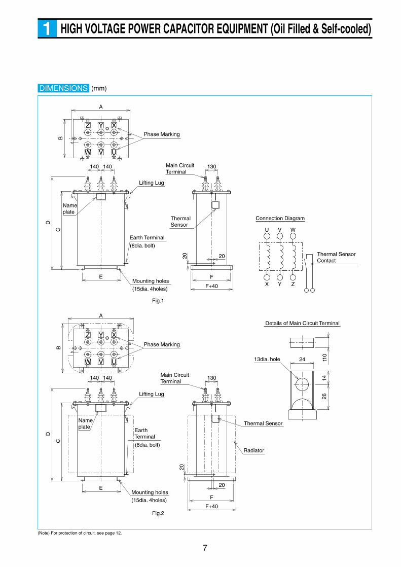
HIGH VOLTAGE POWER CAPACITOR EQUIPMENT (Oil Filled & Self-cooled)1
DIMENSIONS
(Note) For protection of circuit, see page 12.
A
140
E
130
X Y Z
U V W
20 20
F
F+40
140
BC
D
YZ X
VW U
24
Fig.1
Details of Main Circuit Terminal
Thermal Sensor Contact
t10
1426
13dia. hole
Phase Marking
Nameplate
Main Circuit Terminal
Lifting Lug
Thermal Sensor
Earth Terminal
(8dia. bolt)
(15dia. 4holes)
Mounting holes
Connection Diagram
A
140
E
130
20
20
F
F+40
140
BC
D
YZ X
VW U
Phase Marking
Nameplate
Main Circuit Terminal
Lifting Lug
Thermal Sensor
Radiator
EarthTerminal
(8dia. bolt)
(15dia. 4holes)
Mounting holes
Fig.2
(mm)

TYPE LV-6 HIGH VOLTAGE CAPACITORS (for L=13%) Combined Output 10-500kvar
8
HIGH VOLTAGE POWER CAPACITOR EQUIPMENT (Oil Filled & Self-cooled)1
Type LV-6, oil filled and self cooled
Installation Location Indoor & outdoor
Temperature Class –20/B
Output Tolerance –5% to +15% of rated output
(Unbalance among phases 1.08
or less)
Voltage Withstand T - T : 2 x rated voltage
T - C : 16kV (for 3510V)
22kV (for 7020V)
SPECIFICATIONS
Ambient temperature –20°C to +50°C, provided 24
hour average is 45°C max. )(
Insulation Level 16/45kV, 22/60kV
Dissipation Factor 0.025% max. at 20°C
110% of rating (12 hours max.
per 24 hours)
130% of rating (not including
current due to cap. tol.)
Discharge Resistors Discharge to 50V or less in 5
minutes
Paint Color Munsell 5Y7/1
Applicable Standard JIS C 4902-1998
System Voltage : 3300V or 6600V
RATINGS LV-6 (for L=13%) 10-500kvar
LV6 CC010R13ELV6 CC015R13ELV6 CC020R13ELV6 CC025R13ELV6 CC030R13ELV6 C5050R13ELV6 C6050R13ELV6 C5075R13ELV6 C6075R13ELV6 C5100R13ELV6 C6100R13ELV6 C5150R13ELV6 C6150R13ELV6 C5200R13ELV6 C6200R13ELV6 C5250R13ELV6 C6250R13ELV6 C5300R13ELV6 C6300R13ELV6 C5400R13ELV6 C6400R13ELV6 C5500R13ELV6 C6500R13E
150150150150170250210335310440360400360510430590520690590680540840720
3503503503503704504105355106405606105707206408007309008008907501050930
–––––
170130230220330240270220370270430370450430450390550500
15151515162119272533285147645473658573135108165142
C F NGross mass
(kg)Fig.Rated Voltage
(V)
7590or
3790
Combined Output(kvar)10/1215/1820/2425/3030/36
11.5/13.817.2/20.723.0/27.628.7/34.534.5/41.4
50
75
100
150
200
250
300
400
500
57.5
86.2
115
172
230
287
345
460
575
1.75/2.102.62/3.153.50/4.204.37/5.255.25/6.30
0.875/1.051.31/1.571.75/2.102.19/2.622.62/3.15
8.75
13.1
17.5
26.2
35.0
43.7
52.5
70.0
87.5
4.37
6.56
8.75
13.1
17.5
21.9
26.2
35.0
43.7
50/6050/6050/6050/6050/60
506050605060506050605060506050605060
Rated Frequency(Hz)
Rated Output(kvar)
Rated Current (A)3300V 6600V
Part NumberDimensions (mm)
1
2
3
4
(Note) 1. The asterisk denotes voltage. 33 and 66 represent 3300V and 6600V respectively.
Permissible Overload
Maximum Voltage
Permissible Overload
Maximum Current
9
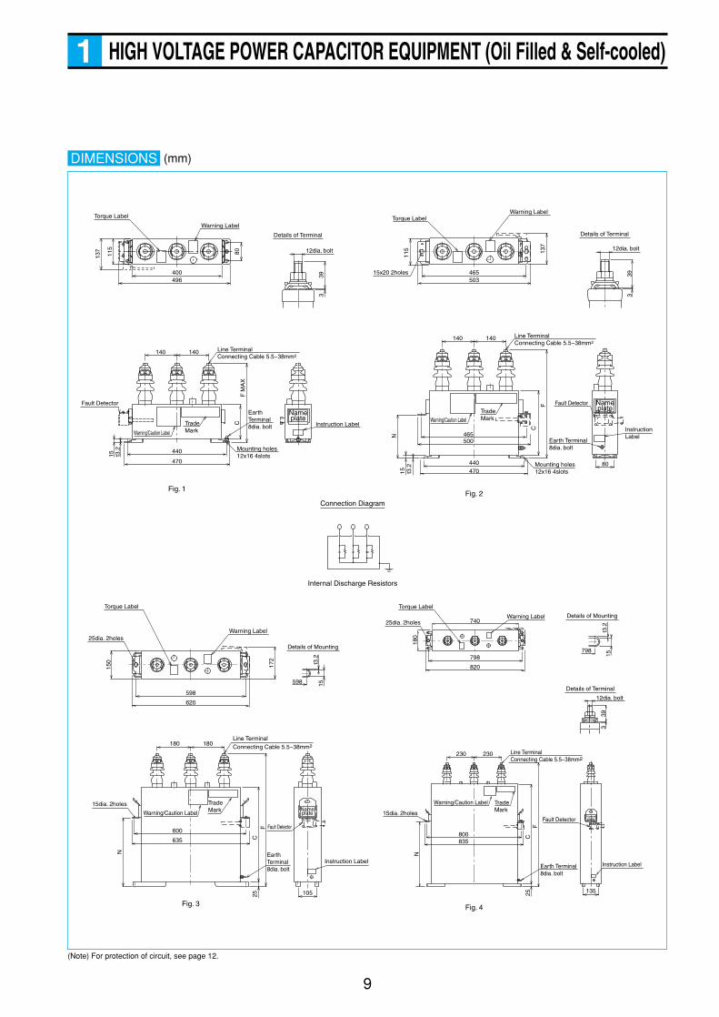
HIGH VOLTAGE POWER CAPACITOR EQUIPMENT (Oil Filled & Self-cooled)1
DIMENSIONS
115
140 140
39
12dia. bolt
3
Mounting holes12x16 4slots
Fig. 1
Trade Mark
Earth Terminal8dia. bolt
80
F
C
440470t3
.215
N
Instruction Label
Warning LabelTorque LabelTorque Label
Line TerminalConnecting Cable 5.5~38mm2
Fault Detector
39
Details of Terminal Details of Terminal
3
Fig. 2
Fig. 4Fig. 3
465500
39
12dia. bolt
Details of Terminal
3
230230
15dia. 2holes
25dia. 2holes
Warning/Caution Label
15t3
.2
Details of Mounting
798
Instruction LabelEarth Terminal8dia. bolt
Fault Detector
Trade Mark
800835
180
740
C25
F
Line TerminalConnecting Cable 5.5~38mm2
Warning Label
Torque Label
Connection Diagram
Internal Discharge Resistors
180180
15dia. 2holes
25dia. 2holes
Warning/Caution Label
Warning Label
15t3
.2
Details of Mounting
598
Torque Label
Instruction LabelEarth Terminal8dia. bolt
Line TerminalConnecting Cable 5.5~38mm2
Fault Detector
TradeMark
600
635
N
150
C25
F
598
620
105
798
820
135
N
172
15x20 2holes
Line TerminalConnecting Cable 5.5~38mm2
Warning Label
140
470
496400
503465
440
80
15 t3.2
115
140
Warning/Caution Label
Warning/Caution LabelTrade Mark
Earth Terminal8dia. bolt Instruction Label
F M
AX
C
Mounting holes12x16 4slots
Fault Detector
12dia. bolt
Nameplate
Nameplate
Nameplate
Nameplate
137 13
7
(Note) For protection of circuit, see page 12.
(mm)
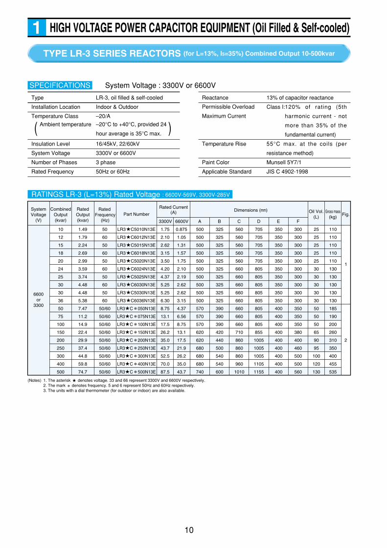
TYPE LR-3 SERIES REACTORS (for L=13%, I5=35%) Combined Output 10-500kvar
10
HIGH VOLTAGE POWER CAPACITOR EQUIPMENT (Oil Filled & Self-cooled)1
Type LR-3, oil filled & self-cooled
Installation Location Indoor & Outdoor
Temperature Class –20/A
Insulation Level 16/45kV, 22/60kV
System Voltage 3300V or 6600V
Number of Phases 3 phase
Rated Frequency 50Hz or 60Hz
SPECIFICATIONS
Ambient temperature –20°C to +40°C, provided 24
hour average is 35°C max. )(
Reactance 13% of capacitor reactance
Class I:120% of rating (5th
harmonic current - not
more than 35% of the
fundamental current)
Temperature Rise 55°C max. at the coils (per
resistance method)
Paint Color Munsell 5Y7/1
Applicable Standard JIS C 4902-1998
System Voltage : 3300V or 6600V
RATINGS LR-3 (L=13%) Rated Voltage : 6600V-569V, 3300V-285V
SystemVoltage
(V)
6600or
3300
CombinedOutput(kvar)
10
12
15
18
20
24
25
30
30
36
50
75
100
150
200
250
300
400
500
50
60
50
60
50
60
50
60
50
60
50/60
50/60
50/60
50/60
50/60
50/60
50/60
50/60
50/60
1.49
1.79
2.24
2.69
2.99
3.59
3.74
4.48
4.48
5.38
7.47
11.2
14.9
22.4
29.9
37.4
44.8
59.8
74.7
1.75
2.10
2.62
3.15
3.50
4.20
4.37
5.25
5.25
6.30
8.75
13.1
17.5
26.2
35.0
43.7
52.5
70.0
87.5
0.875
1.05
1.31
1.57
1.75
2.10
2.19
2.62
2.62
3.15
4.37
6.56
8.75
13.1
17.5
21.9
26.2
35.0
43.7
500
500
500
500
500
500
500
500
500
500
570
570
570
620
620
680
680
680
740
325
325
325
325
325
325
325
325
325
325
390
390
390
420
440
500
540
540
600
560
560
560
560
560
660
660
660
660
660
660
660
660
710
860
860
860
960
1010
705
705
705
705
705
805
805
805
805
805
805
805
805
855
1005
1005
1005
1105
1155
350
350
350
350
350
350
350
350
350
350
400
400
400
400
400
400
400
400
400
300
300
300
300
300
300
300
300
300
300
350
350
350
380
400
460
500
500
560
25
25
25
25
25
30
30
30
30
30
50
50
50
65
90
95
100
120
130
110
110
110
110
110
130
130
130
130
130
185
190
200
260
310
350
400
455
535
LR3 C5010N13E
LR3 C6012N13E
LR3 C5015N13E
LR3 C6018N13E
LR3 C5020N13E
LR3 C6024N13E
LR3 C5025N13E
LR3 C6030N13E
LR3 C5030N13E
LR3 C6036N13E
LR3 C 050N13E
LR3 C 075N13E
LR3 C 100N13E
LR3 C 150N13E
LR3 C 200N13E
LR3 C 250N13E
LR3 C 300N13E
LR3 C 400N13E
LR3 C 500N13E
RatedOutput(kvar)
Rated Current(A) Oil Vol.
(L)Gross mass
(kg) Fig.
3300V 6600V A B C D E F
Part NumberDimensions (mm)Rated
Frequency (Hz)
1
2
(Notes) 1. The asterisk denotes voltage. 33 and 66 represent 3300V and 6600V respectively.2. The mark denotes frequency. 5 and 6 represent 50Hz and 60Hz respectively.3. The units with a dial thermometer (for outdoor or indoor) are also available.
Permissible Overload
Maximum Current

11
HIGH VOLTAGE POWER CAPACITOR EQUIPMENT (Oil Filled & Self-cooled)1
DIMENSIONS
(Note) For protection of circuit, see page 12.
A
140
E
130
20 20
F
F+40
140
BC
D
YZ X
VW U
24
Details of Main Circuit Terminal
t10
1426
13dia. hole
Phase Marking
Nameplate
Main Circuit Terminal
Lifting Lug
ThermalSensor
Earth Terminal
(8dia. blot)
(15dia. 4holes)
Mounting holes
Fig.1
Fig.2
A
140
E
130
20
20
F
F+40
140
BC
D
YZ X
VW U
Phase Marking
Main Circuit Terminal
Lifting Lug
Thermal Sensor
Radiator
Earth Terminal
(8dia. blot)
(15dia. 4holes)
Mounting holes
X Y Z
U V W
Thermal Sensor Contact
Connection Diagram
Nameplate
(mm)
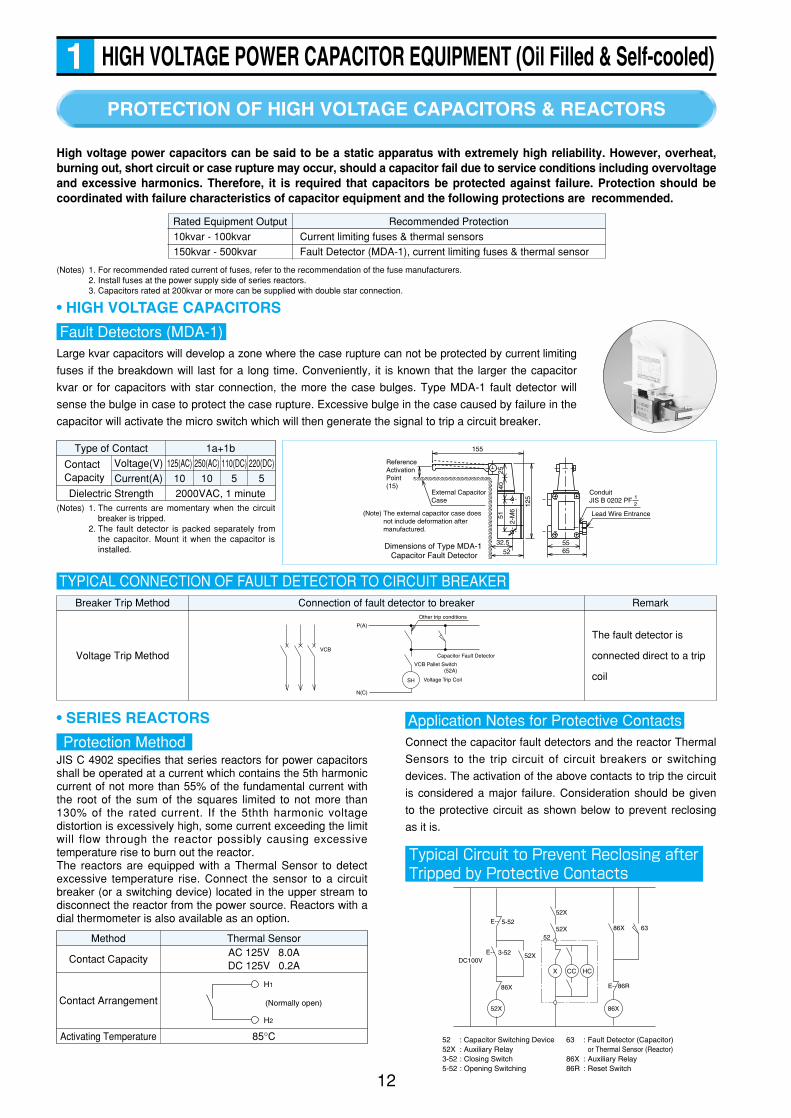
Method Thermal Sensor
Contact CapacityAC 125V 8.0ADC 125V 0.2A
Contact Arrangement
Activating Temperature 85°C
Breaker Trip Method Connection of fault detector to breaker
Voltage Trip Method
The fault detector is
connected direct to a trip
coil
Remark
Type of Contact
ContactCapacity
Voltage(V)
Current(A)
1a+1b
Dielectric Strength 2000VAC, 1 minute
125(AC) 250(AC) 110(DC) 220(DC)
10 10 5 5
Rated Equipment Output Recommended Protection
PROTECTION OF HIGH VOLTAGE CAPACITORS & REACTORS
12
HIGH VOLTAGE POWER CAPACITOR EQUIPMENT (Oil Filled & Self-cooled)1
High voltage power capacitors can be said to be a static apparatus with extremely high reliability. However, overheat,burning out, short circuit or case rupture may occur, should a capacitor fail due to service conditions including overvoltageand excessive harmonics. Therefore, it is required that capacitors be protected against failure. Protection should becoordinated with failure characteristics of capacitor equipment and the following protections are recommended.
• HIGH VOLTAGE CAPACITORS
Large kvar capacitors will develop a zone where the case rupture can not be protected by current limiting
fuses if the breakdown will last for a long time. Conveniently, it is known that the larger the capacitor
kvar or for capacitors with star connection, the more the case bulges. Type MDA-1 fault detector will
sense the bulge in case to protect the case rupture. Excessive bulge in the case caused by failure in the
capacitor will activate the micro switch which will then generate the signal to trip a circuit breaker.
Fault Detectors (MDA-1)
(Notes) 1. The currents are momentary when the circuitbreaker is tripped.
2. The fault detector is packed separately fromthe capacitor. Mount it when the capacitor isinstalled.
155
32.552
5565
2-M
6
51
125
4025
External Capacitor Case
ConduitJIS B 0202 PF
21
(Note) The external capacitor case does not include deformation after manufactured.
Dimensions of Type MDA-1 Capacitor Fault Detector
Lead Wire Entrance
Reference Activation Point(15)
• SERIES REACTORS
JIS C 4902 specifies that series reactors for power capacitorsshall be operated at a current which contains the 5th harmoniccurrent of not more than 55% of the fundamental current withthe root of the sum of the squares limited to not more than130% of the rated current. If the 5thth harmonic voltagedistortion is excessively high, some current exceeding the limitwill flow through the reactor possibly causing excessivetemperature rise to burn out the reactor.The reactors are equipped with a Thermal Sensor to detectexcessive temperature rise. Connect the sensor to a circuitbreaker (or a switching device) located in the upper stream todisconnect the reactor from the power source. Reactors with adial thermometer is also available as an option.
Protection Method Connect the capacitor fault detectors and the reactor Thermal
Sensors to the trip circuit of circuit breakers or switching
devices. The activation of the above contacts to trip the circuit
is considered a major failure. Consideration should be given
to the protective circuit as shown below to prevent reclosing
as it is.
Typical Circuit to Prevent Reclosing afterTripped by Protective Contacts
Application Notes for Protective Contacts
DC100V
E--
E--
E-- 86R
86X 635-52
3-52
86X
52X
52X
52X
52X52
86X
X CC HC
52 : Capacitor Switching Device52X : Auxiliary Relay3-52 : Closing Switch5-52 : Opening Switching
63 : Fault Detector (Capacitor)or Thermal Sensor (Reactor)
86X : Auxiliary Relay86R : Reset Switch
H1
H2
(Normally open)
Other trip conditions
Capacitor Fault Detector
VCB Pallet Switch(52A)
Voltage Trip CoilSH
P(A)
N(C)
VCB
TYPICAL CONNECTION OF FAULT DETECTOR TO CIRCUIT BREAKER
Current limiting fuses & thermal sensors
Fault Detector (MDA-1), current limiting fuses & thermal sensor
10kvar - 100kvar
150kvar - 500kvar
(Notes) 1. For recommended rated current of fuses, refer to the recommendation of the fuse manufacturers.2. Install fuses at the power supply side of series reactors.3. Capacitors rated at 200kvar or more can be supplied with double star connection.
Rated Voltage
(V)
3510
or
7020
200 21350
6035.0 17.5
390
340
600
550
270
220
67
59
23
20LV6 C5200R26AE
LV6 C6200R26AE
250 26650
6043.7 21.9
420
410
630
610
280
270
74
71
22
23LV6 C5250R26AE
LV6 C6250R26AE
300 31950
6052.5 26.2
480
420
690
630
340
280
81
74
24
22LV6 C5300R26AE
LV6 C6300R26AE
Combined Output
(kvar)
Rated Output
(kvar)
Rated Frequency
(Hz)Part Number
Rated Current (A)
3510V 7020V
Dimensions (mm)
C F N
Gross mass
(kg)
Oil Vol.
(L)
HIGH VOLTAGE POWER CAPACITOR EQUIPMENT (Oil Filled & Self-cooled)1
13
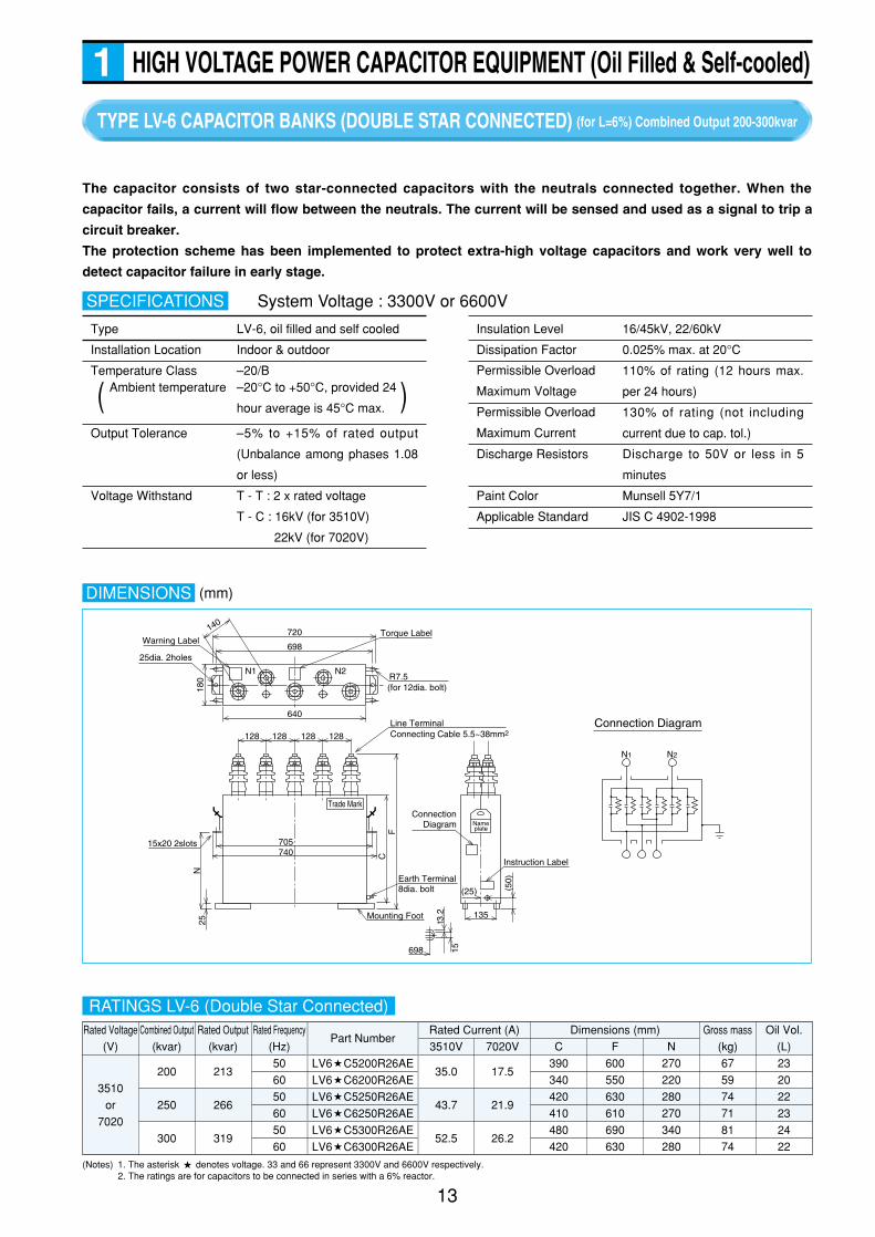
TYPE LV-6 CAPACITOR BANKS (DOUBLE STAR CONNECTED) (for L=6%) Combined Output 200-300kvar
Type LV-6, oil filled and self cooled
Installation Location Indoor & outdoor
Temperature Class –20/B
Output Tolerance –5% to +15% of rated output
(Unbalance among phases 1.08
or less)
Voltage Withstand T - T : 2 x rated voltage
T - C : 16kV (for 3510V)
22kV (for 7020V)
SPECIFICATIONS
Ambient temperature –20°C to +50°C, provided 24
hour average is 45°C max. )(
Insulation Level 16/45kV, 22/60kV
Dissipation Factor 0.025% max. at 20°C
110% of rating (12 hours max.
per 24 hours)
130% of rating (not including
current due to cap. tol.)
Discharge Resistors Discharge to 50V or less in 5
minutes
Paint Color Munsell 5Y7/1
Applicable Standard JIS C 4902-1998
The capacitor consists of two star-connected capacitors with the neutrals connected together. When the
capacitor fails, a current will flow between the neutrals. The current will be sensed and used as a signal to trip a
circuit breaker.
The protection scheme has been implemented to protect extra-high voltage capacitors and work very well to
detect capacitor failure in early stage.
DIMENSIONS
720Warning Label
698
640
25dia. 2holes
R7.5(for 12dia. bolt)
N1 N2
180
140
128 128 128 128
Line Terminal
Torque Label
Earth Terminal8dia. bolt
Connecting Cable 5.5~38mm2
FC
Mounting Foot
705
25N
74015x20 2slots
Trade Mark
698
135
(25) (50)
15
t3.2
ConnectionDiagram
Instruction Label
Nameplate
N1
Connection Diagram
N2
RATINGS LV-6 (Double Star Connected)
System Voltage : 3300V or 6600V
(Notes) 1. The asterisk denotes voltage. 33 and 66 represent 3300V and 6600V respectively.2. The ratings are for capacitors to be connected in series with a 6% reactor.
Permissible Overload
Maximum Voltage
Permissible Overload
Maximum Current
(mm)

Rated Voltage
(V)
3510
or
7020
1000 106050
60175 87.5
970
970
990
990
1,690
1,560
1,250
1,110
390
360FHZ C510ER26E
FHZ C610ER26E
2000 213050
60350 175
970
970
1,290
1,170
2,580
2,580
2,800
2,600
940
880FHZ C520ER26E
FHZ C620ER26E
3000 319050
60325 262
1,280
1,160
1,380
1,380
2,580
2,580
4,100
3,600
1360
1280FHZ C530ER26E
FHZ C630ER26E
Combined Output
(kvar)
Rated Output
(kvar)
Rated Frequency
(Hz)Part Number
Rated Current (A)
3510V 7020V
Dimensions (mm)
A B F
Gross mass
(kg)
Oil Vol.
(L)
TYPE FHZ HIGH VOLTAGE CAPACITORS (for L=6%) Combined Output 1000-3000kvar
14
HIGH VOLTAGE POWER CAPACITOR EQUIPMENT (Oil Filled & Self-cooled)1
Type FHZ high output capacitors offer the advantages given by high output units, making use of high
performance of film dielectric layers.
qq Low Power Loss
Running power can be saved as the loss is reduced to
approximately 1/2 of the conventional paper capacitors.
ww High Resistance for Contamination
Number of bushings is minimized as the capacitors are
enclosed in a large tank. In addition, the capacitors are
FEATURESimmune to leaks resulting from rust due to thick tank plates
used. It is recommended to install the capacitors
especially at any contaminated locations.
ee Easy maintenance
Daily maintenance is not required due to the simple
external construction.
DIMENSIONS
Lifting Lug
Name Plate
Mounting Foot
F
Outgoing Box for CT secondary
Earth Terminal22~60mm2
Line Terminal A
B
Conduit Coupling(PFI thread)
Pressure Relief
Connection Diagram
Type FHZ, oil filled and self cooled
Installation Location Indoor & outdoor
Temperature Class –20/A
Output Tolerance –5% to +15% of rated output
(Unbalance among phases 1.08
or less)
Voltage Withstand T - T : 2 x rated voltage
T - C : 16kV (for 3510V)
22kV (for 7020V)
SPECIFICATIONS
Ambient temperature –20°C to +40°C, provided 24
hour average is 35°C max. )(
Insulation Level 16/45kV, 22/60kV
Dissipation Factor 0.15% max. at 20°C
110% of rating (12 hours max.
per 24 hours)
130% of rating (not including
current due to cap. tol.)
Discharge Resistors Discharge to 50V or less in 5
minutes
Protection Scheme Detection of current between the
double star-connected neutrals
Paint Color Munsell 5Y7/1
Applicable Standard JIS C 4902-1998
System Voltage : 3300V or 6600V
RATINGS LV-6 (Double Star Connected)
(Notes) 1. The asterisk denotes voltage. 33 and 66 represent 3300V and 6600V respectively.2. The ratings are for capacitors to be connected in series with a 6% reactor.3. High output single units and extra-high voltage units not shown above are also available.
Permissible Overload
Maximum Voltage
Permissible Overload
Maximum Current
(mm)
HIGH VOLTAGE POWER CAPACITOR EQUIPMENT (Oil Filled & Self-cooled)1
15
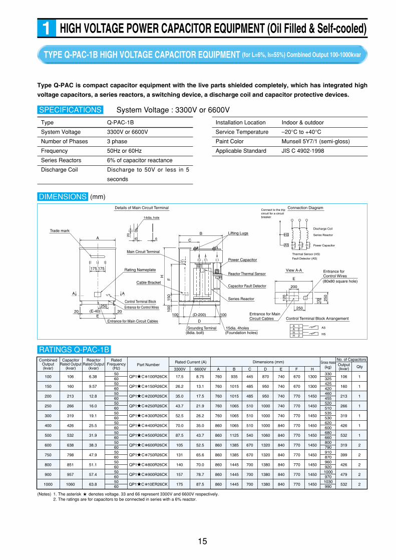
TYPE Q-PAC-1B HIGH VOLTAGE CAPACITOR EQUIPMENT (for L=6%, I5=55%) Combined Output 100-1000kvar
Type Q-PAC-1B
System Voltage 3300V or 6600V
Number of Phases 3 phase
Frequency 50Hz or 60Hz
Series Reactors 6% of capacitor reactance
Discharge Coil Discharge to 50V or less in 5
seconds
SPECIFICATIONS
Installation Location Indoor & outdoor
Service Temperature –20°C to +40°C
Paint Color Munsell 5Y7/1 (semi-gloss)
Applicable Standard JIS C 4902-1998
System Voltage : 3300V or 6600V
DIMENSIONS
20
40 6
250
200
E
View A-A
Control Terminal Block Arrangement
120
250
130
Details of Main Circuit Terminal
HS
AS
A 1A 2 AS
HSH 1H 2
A
A A
175 175
Series Reactor
20 (E-40)E
25020
B
C
F
H
150
100
100(D-200)
D
100
14dia. hole
Trade mark
Rating Nameplate
Entrance for Main Circuit Cables
Entrance for Control Wires
Control Terminal Block
Main Circuit Terminal
Cable BracketCapacitor Fault Detector
Reactor Thermal Sensor
Power Capacitor
Lifting Lugs
Entrance for Main Circuit Cables
Grounding Terminal(8dia. bolt)
15dia. 4holes(Foundation holes)
NP
NP
Entrance for Control Wires(80x80 square hole)
Connection Diagram
Discharge Coil
Connect to the trip circuit for a circuit breaker
Series Reactor
Power Capacitor
Thermal Sensor (HS)
Fault Detector (AS)
Gross mass(kg)
Output(kvar) Qty
No. of CapacitorsCombinedOutput(kvar)
CapacitorRated Output
(kvar)
ReactorRated Output
(kvar)
RatedFrequency
(Hz)
QP1 C 100R26CK
QP1 C 150R26CK
QP1 C 200R26CK
QP1 C 250R26CK
QP1 C 300R26CK
QP1 C 400R26CK
QP1 C 500R26CK
QP1 C 600R26CK
QP1 C 750R26CK
QP1 C 800R26CK
QP1 C 900R26CK
QP1 C 10ER26CK
Rated Current (A)
3300V 6600V A B C D E F HPart Number
Dimensions (mm)
506050605060506050605060506050605060506050605060
100
150
200
250
300
400
500
600
750
800
900
1000
106
160
213
266
319
426
532
638
798
851
957
1060
6.38
9.57
12.8
16.0
19.1
25.5
31.9
38.3
47.9
51.1
57.4
63.8
17.5
26.2
35.0
43.7
52.5
70.0
87.5
105
131
140
157
175
8.75
13.1
17.5
21.9
26.2
35.0
43.7
52.5
65.6
70.0
78.7
87.5
760
760
760
760
760
860
860
860
860
860
860
860
935
1015
1015
1065
1065
1065
1125
1385
1385
1445
1445
1445
445
485
485
510
510
510
540
670
670
700
700
700
870
950
950
1000
1000
1000
1060
1320
1320
1380
1380
1380
740
740
740
740
740
840
840
840
840
840
840
840
670
670
770
770
770
770
770
770
770
770
770
770
1300
1300
1450
1450
1450
1450
1450
1450
1450
1450
1450
1450
106
160
213
266
319
426
532
319
399
426
479
532
1
1
1
1
1
1
1
2
2
2
2
2
33032542542046045552051053553062060068066080079091087096092010009701030990
(Notes) 1. The asterisk denotes voltage. 33 and 66 represent 3300V and 6600V respectively.2. The ratings are for capacitors to be connected in series with a 6% reactor.
RATINGS Q-PAC-1B
Type Q-PAC is compact capacitor equipment with the live parts shielded completely, which has integrated high
voltage capacitors, a series reactors, a switching device, a discharge coil and capacitor protective devices.
(mm)
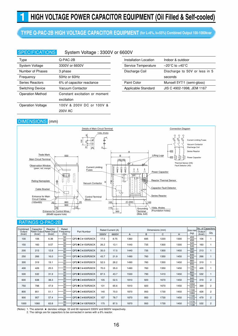
TYPE Q-PAC-2B HIGH VOLTAGE CAPACITOR EQUIPMENT (for L=6%, I5=55%) Combined Output 100-1000kvar
16
HIGH VOLTAGE POWER CAPACITOR EQUIPMENT (Oil Filled & Self-cooled)1
DIMENSIONS
4040
20 40 6
100
Details of Main Circuit Terminal
HS
AS
H
A
300
100 100(C-200)C
Grounding Terminal
15dia. 4holes
Series Reactor
Capacitor Fault Detector
Reactor Thermal Sensor
Power Capacitor
Lifting Lugs
(8dia. bolt)
(Foundation holes)110
150
Current Limiting Fuses
Vacuum Contactor
150
B
N P
NP
Trade Mark
Main Circuit Terminal
Rating Nameplate
Cable Bracket
Entrance for Main Circuit Cables
Entrance for Control Wires
Control TerminalBlock
930
20 860900
20
135 110
(80x80 square hole)
Observation Window(green, red, orange)
Connection Diagram
Current Limiting Fuses
Vacuum Contactor
Discharge Coil
Series Reactor
Power Capacitor
Thermal Sensor (HS)Fault Detector (AS)
14dia. 2holes
(120x450)
Type Q-PAC-2B
System Voltage 3300V or 6600V
Number of Phases 3 phase
Frequency 50Hz or 60Hz
Series Reactors 6% of capacitor reactance
Switching Device Vacuum Contactor
Operation Method Constant excitation or moment
excitation
Operation Voltage 100V & 200V DC or 100V &
200V AC
SPECIFICATIONS
Installation Location Indoor & outdoor
Service Temperature –20°C to +40°C
Discharge Coil Discharge to 50V or less in 5
seconds
Paint Color Munsell 5Y7/1 (semi-gloss)
Applicable Standard JIS C 4902-1998, JEM 1167
System Voltage : 3300V or 6600V
Gross mass(kg)
Output(kvar) Qty
No. of CapacitorsCombined Output(kvar)
Capacitor Rated Output
(kvar)
Reactor Rated Output
(kvar)
Rated Frequency
(Hz)
QP2 C 100R26CK
QP2 C 150R26CK
QP2 C 200R26CK
QP2 C 250R26CK
QP2 C 300R26CK
QP2 C 400R26CK
QP2 C 500R26CK
QP2 C 600R26CK
QP2 C 750R26CK
QP2 C 800R26CK
QP2 C 900R26CK
QP2 C 10ER26CK
Rated Current (A)
3300V 6600V HCBAPart Number
Dimensions (mm)
506050605060506050605060506050605060506050605060
100
150
200
250
300
400
500
600
750
800
900
1000
106
160
213
266
319
426
532
638
798
851
957
1060
6.38
9.57
12.8
16.0
19.1
25.5
31.9
38.3
47.9
51.1
57.4
63.8
17.5
26.2
35.0
43.7
52.5
70.0
87.5
105
131
140
157
175
8.75
13.1
17.5
21.9
26.2
35.0
43.7
52.5
65.6
70.0
78.7
87.5
1300
1300
1450
1450
1450
1450
1450
1450
1450
1450
1450
1450
1220
1300
1300
1350
1350
1350
1410
1670
1670
1730
1730
1730
695
735
735
760
760
760
790
920
920
950
950
950
1360
1440
1440
1490
1490
1490
1550
1810
1810
1870
1870
1870
45545054554058558064063566065074072080078094093010501010110010601140111011701130
106
160
213
266
319
426
532
319
399
426
479
532
1
1
1
1
1
1
1
2
2
2
2
2
(Notes) 1. The asterisk denotes voltage. 33 and 66 represent 3300V and 6600V respectively.2. The ratings are for capacitors to be connected in series with a 6% reactor.
RATINGS Q-PAC-2B
(mm)
17
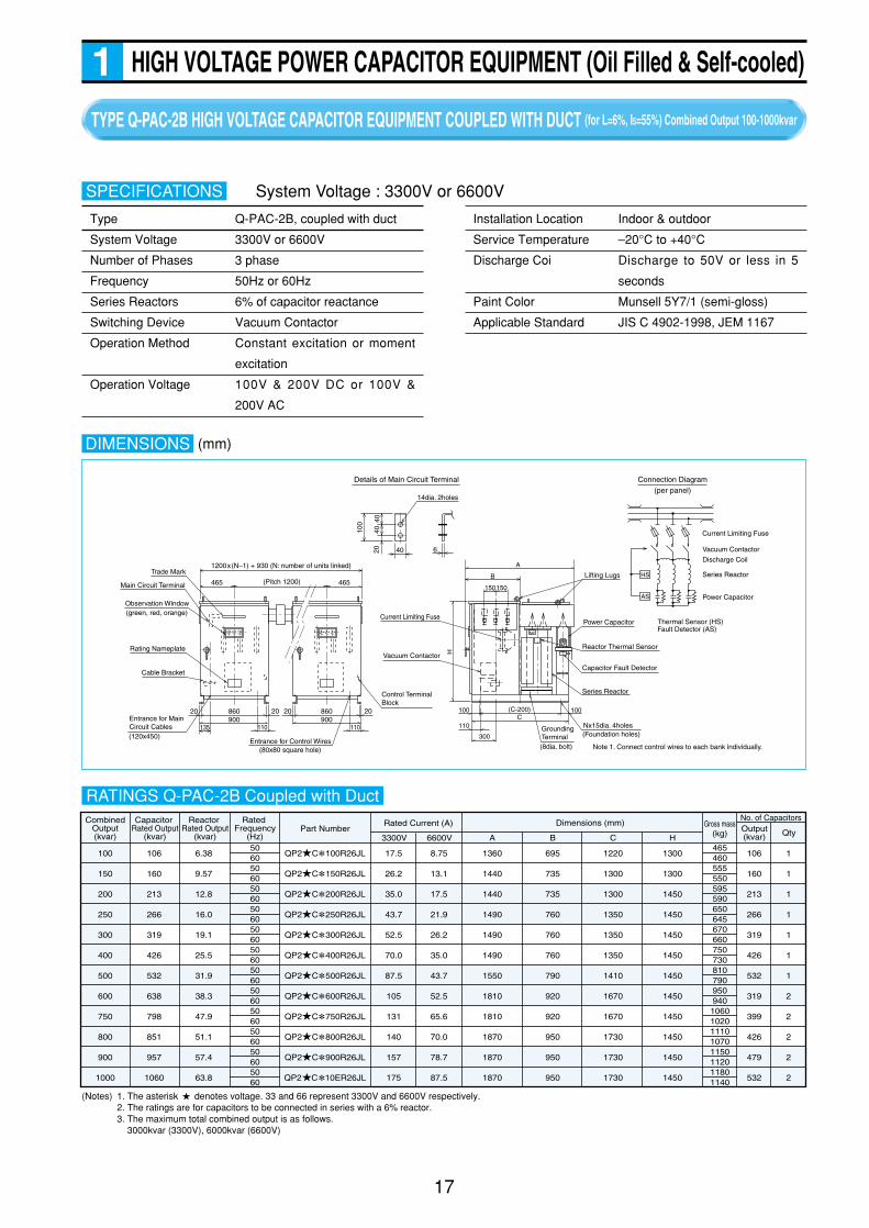
HIGH VOLTAGE POWER CAPACITOR EQUIPMENT (Oil Filled & Self-cooled)1TYPE Q-PAC-2B HIGH VOLTAGE CAPACITOR EQUIPMENT COUPLED WITH DUCT (for L=6%, I5=55%) Combined Output 100-1000kvar
Type Q-PAC-2B, coupled with duct
System Voltage 3300V or 6600V
Number of Phases 3 phase
Frequency 50Hz or 60Hz
Series Reactors 6% of capacitor reactance
Switching Device Vacuum Contactor
Operation Method Constant excitation or moment
excitation
Operation Voltage 100V & 200V DC or 100V &
200V AC
SPECIFICATIONS
Installation Location Indoor & outdoor
Service Temperature –20°C to +40°C
Discharge Coi Discharge to 50V or less in 5
seconds
Paint Color Munsell 5Y7/1 (semi-gloss)
Applicable Standard JIS C 4902-1998, JEM 1167
System Voltage : 3300V or 6600V
DIMENSIONS
Observation Window (green, red, orange)
(120x450)
465 465
20 860900
20
135 110
20 860900
20
110
Note 1. Connect control wires to each bank individually.
4040
20 40 6
100
H
A
300
100 100(C-200)C
GroundingTerminal
Nx15dia. 4holes
Reactor Thermal Sensor
(8dia. bolt)
(Foundation holes)110
150150
B
NP
NP
HS
AS
Trade Mark
Main Circuit Terminal
Rating Nameplate
Cable Bracket
Entrance for Main Circuit Cables
(Pitch 1200)
Entrance for Control Wires
1200x(N–1) + 930 (N: number of units linked)
(80x80 square hole)
Control Terminal Block
Current Limiting Fuse
Vacuum Contactor
Series Reactor
Capacitor Fault Detector
Power Capacitor
Lifting Lugs
Connection Diagram(per panel)
Details of Main Circuit Terminal
14dia. 2holes
Current Limiting Fuse
Vacuum Contactor
Discharge Coil
Series Reactor
Power Capacitor
Thermal Sensor (HS)Fault Detector (AS)
Gross mass(kg)
Output(kvar) Qty
No. of CapacitorsCombinedOutput(kvar)
Capacitor Rated Output
(kvar)
Reactor Rated Output
(kvar)
Rated Frequency
(Hz)
QP2 C 100R26JL
QP2 C 150R26JL
QP2 C 200R26JL
QP2 C 250R26JL
QP2 C 300R26JL
QP2 C 400R26JL
QP2 C 500R26JL
QP2 C 600R26JL
QP2 C 750R26JL
QP2 C 800R26JL
QP2 C 900R26JL
QP2 C 10ER26JL
Rated Current (A)
3300V 6600V HCBAPart Number
Dimensions (mm)
506050605060506050605060506050605060506050605060
100
150
200
250
300
400
500
600
750
800
900
1000
106
160
213
266
319
426
532
638
798
851
957
1060
6.38
9.57
12.8
16.0
19.1
25.5
31.9
38.3
47.9
51.1
57.4
63.8
17.5
26.2
35.0
43.7
52.5
70.0
87.5
105
131
140
157
175
8.75
13.1
17.5
21.9
26.2
35.0
43.7
52.5
65.6
70.0
78.7
87.5
1300
1300
1450
1450
1450
1450
1450
1450
1450
1450
1450
1450
106
160
213
266
319
426
532
319
399
426
479
532
1
1
1
1
1
1
1
2
2
2
2
2
46546055555059559065064567066075073081079095094010601020111010701150112011801140
1220
1300
1300
1350
1350
1350
1410
1670
1670
1730
1730
1730
695
735
735
760
760
760
790
920
920
950
950
950
1360
1440
1440
1490
1490
1490
1550
1810
1810
1870
1870
1870
(Notes) 1. The asterisk denotes voltage. 33 and 66 represent 3300V and 6600V respectively.2. The ratings are for capacitors to be connected in series with a 6% reactor.3. The maximum total combined output is as follows.
3000kvar (3300V), 6000kvar (6600V)
RATINGS Q-PAC-2B Coupled with Duct
(mm)

50
60
System Voltage
(V)
Frequency
(Hz)
Combined Output
(kvar)
Rated Current (A)
3300V 6600V
No. of Capacitors
(kvar x No. of steps)
Gross mass
(kg)Fig.
3300
or
6600
50
60200 35.0 17.5 100 x 2 1220
50
60300 52.5 26.2 150 x 2 1240
50
60400 70.0 35.0 200 x 2
1360
1330
300 52.5 26.2 100 x 3 1500
50
60450 78.7 39.4 150 x 3 1670
50
60600 105 52.5 200 x 3
1950
19002
1
TYPE HA-PAC HIGH VOLTAGE CAPACITOR EQUIPMENT WITH AUTOMATIC CAPACITOR CONTROL (for L=6%, I5=55%) Combined Output 200-600kvar
18
HIGH VOLTAGE POWER CAPACITOR EQUIPMENT (Oil Filled & Self-cooled)1
DIMENSIONS
High Voltage Entrance 100°
Low voltage Entrance(500x100 square hole)
Nameplate
1670
1600
Rating Nameplate
16001690
1865
2370
Nameplate
2470
2400
Rating Nameplate
16001690
1865
Main Circuit Terminal
Cable Bracket
2370
Fig. 1 Fig. 2
1600
1560
2020
(Bas
e D
imen
sion
)
(Base Dimension)
300
150150
1600
(Bas
e D
imen
sion
)
(Base Dimension)
300
150150
400 800
1600
800800400
2020
1560
400
2400
400
18dia. 4holesthrough hole 18dia. 6holes through hole
High Voltage Entrance 100°
Foundation Drawing Foundation Drawing
Connection Diagram(For 3 steps)
CT VT AC100V
SQ-S4
Main Circuit Terminal
Cable Bracket
Low voltage Entrance(500x100 square hole)
Type HA-PAC
System Voltage 3300V or 6600V
Number of Phases 3 phase
Frequency 50Hz or 60Hz
Series Reactors 6% of capacitor reactance
Switching Device Vacuum Contactor
Discharge Coil Discharge to 50V or less in 5
seconds
SPECIFICATIONS
SQ-S4 (reactive power control)
Installation Location Indoor & outdoor
Service Temperature –20°C to +40°C
Paint Color Munsell 5Y7/1
Applicable Standard JIS C 4902-1998, JEM 1167
System Voltage : 3300V or 6600V
RATINGS HA-PAC
Automatic Capacitor
Control
(mm)
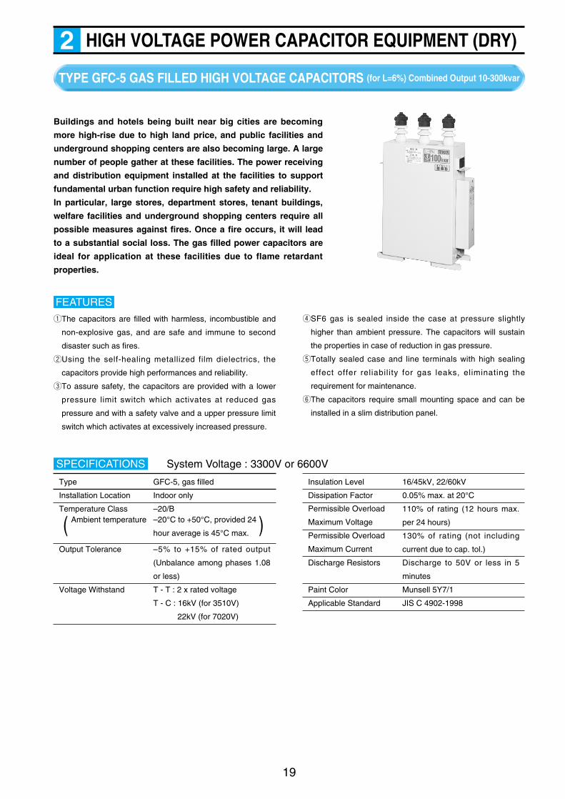
HIGH VOLTAGE POWER CAPACITOR EQUIPMENT (DRY)2
Buildings and hotels being built near big cities are becoming
more high-rise due to high land price, and public facilities and
underground shopping centers are also becoming large. A large
number of people gather at these facilities. The power receiving
and distribution equipment installed at the facilities to support
fundamental urban function require high safety and reliability.
In particular, large stores, department stores, tenant buildings,
welfare facilities and underground shopping centers require all
possible measures against fires. Once a fire occurs, it will lead
to a substantial social loss. The gas filled power capacitors are
ideal for application at these facilities due to flame retardant
properties.
qThe capacitors are filled with harmless, incombustible and
non-explosive gas, and are safe and immune to second
disaster such as fires.
wUsing the self-healing metallized film dielectrics, the
capacitors provide high performances and reliability.
eTo assure safety, the capacitors are provided with a lower
pressure limit switch which activates at reduced gas
pressure and with a safety valve and a upper pressure limit
switch which activates at excessively increased pressure.
FEATURES
rSF6 gas is sealed inside the case at pressure slightly
higher than ambient pressure. The capacitors will sustain
the properties in case of reduction in gas pressure.
tTotally sealed case and line terminals with high sealing
effect offer reliability for gas leaks, eliminating the
requirement for maintenance.
yThe capacitors require small mounting space and can be
installed in a slim distribution panel.
19
TYPE GFC-5 GAS FILLED HIGH VOLTAGE CAPACITORS (for L=6%) Combined Output 10-300kvar
Type GFC-5, gas filled
Installation Location Indoor only
Temperature Class –20/B
Output Tolerance –5% to +15% of rated output
(Unbalance among phases 1.08
or less)
Voltage Withstand T - T : 2 x rated voltage
T - C : 16kV (for 3510V)
22kV (for 7020V)
SPECIFICATIONS
Ambient temperature –20°C to +50°C, provided 24
hour average is 45°C max. )(
Insulation Level 16/45kV, 22/60kV
Dissipation Factor 0.05% max. at 20°C
110% of rating (12 hours max.
per 24 hours)
130% of rating (not including
current due to cap. tol.)
Discharge Resistors Discharge to 50V or less in 5
minutes
Paint Color Munsell 5Y7/1
Applicable Standard JIS C 4902-1998
System Voltage : 3300V or 6600V
Permissible Overload
Maximum Voltage
Permissible Overload
Maximum Current

20
HIGH VOLTAGE POWER CAPACITOR EQUIPMENT (DRY)2
DIMENSIONS
12dia. bolt
Warning Label Caution Label
Insulating Cap
15x20 2slots
Connection Diagram
Internal Discharge Resistors
600 Torque Label
Warning Label Caution Label
480
B
545580
500
25
140
15x20 2slots
140 12dia. boltInsulating Cap
560538 Safety
Valve
Warning/Caution Label
DGrounding Terminal8dia. bolt
Instruction Label
Caution Label
Terminal Block
Pressure Switches
Protective Plate
153.
2
625
790
540 Torque Label420
B
485520
500
25
140 140
500478
Safety Valve
Warning/Caution Label
DGrounding Terminal8dia. bolt
Instruction Label
Caution Label
Terminal Block
Pressure Switches
Protective Plate
153.
2
625
790
520 Torque Label
Warning Label Caution Label
400
B
465500
500
25
140
15x20 2slots
140 12dia. boltInsulating Cap
480458
Safety Valve
Warning/Caution Label
D Grounding Terminal8dia. bolt
Instruction Label
Caution Label
Terminal Block
Pressure Switches
Protective Plate
153.
2
625
790
500
140
458480
25
475
640
140
400Torque Label
Warning Label Caution Label
B
Insulating Cap
Warning/Caution Label
Safety ValveProtective Plate
Grounding Terminal8dia. bolt
Instruction Label
153.
2
D
Caution Label
Caution Label
Terminal Block
Pressure Switches
12dia. bolt
12dia. bolt
Details of Terminal
339
Fig. 1 Fig. 2
Fig. 4Fig. 3
Trade Mark
Trade Mark
Trade Mark Trade Mark
Nameplate
Nameplate Nameplate
Nameplate
(Note) For protection of circuit, see page 25.
CIRCUIT PROTECTION
GF5 CC010R26EGF5 CC015R26EGF5 CC020R26EGF5 CC025R26EGF5 CC030R26EGF5 C5050R26EGF5 C6050R26EGF5 C5075R26EGF5 C6075R26EGF5 C5100R26EGF5 C6100R26EGF5 C5150R26EGF5 C6150R26EGF5 C5200R26EGF5 C6200R26EGF5 C5250R26EGF5 C6250R26EGF5 C5300R26EGF5 C6300R26E
115115115115115
21212223242726484751496058666376728378
B DGross mass
(kg) Fig.Rated Voltage(V)
7020or
3510
Combined Output(kvar)10/1215/1820/2425/3030/36
10.6/12.816.0/19.121.3/25.526.6/31.931.9/38.3
50
75
100
150
200
250
300
53.2
79.8
106
160
213
266
319
1.75/2.102.62/3.153.50/4.204.37/5.255.25/6.30
0.875/1.051.31/1.571.75/2.102.19/2.622.62/3.15
8.75
13.1
17.5
26.2
35.0
43.7
52.5
4.37
6.56
8.75
13.1
17.5
21.9
26.2
140
180
200
230
250
270
290
7070707070
95
135
155
185
205
225
245
50/6050/6050/6050/6050/60
5060506050605060506050605060
Rated Frequency(Hz)
Rated Output(kvar)
Rated Current (A)3300V 6600VPart Number
Dimensions (mm)
1
2
3
4
(Note) 1. The asterisk denotes voltage. 33 and 66 represent 3300V and 6600V respectively.
RATINGS GFC-5 (L=6%) 10-300kvar
(mm)
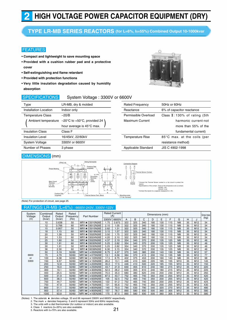
HIGH VOLTAGE POWER CAPACITOR EQUIPMENT (DRY)2
• Compact and lightweight to save mounting space
• Provided with a cushion rubber pad and a protective
cover
• Self-extinguishing and flame retardant
• Provided with protection functions
• Very little insulation degradation caused by humidity
absorption
FEATURES
21
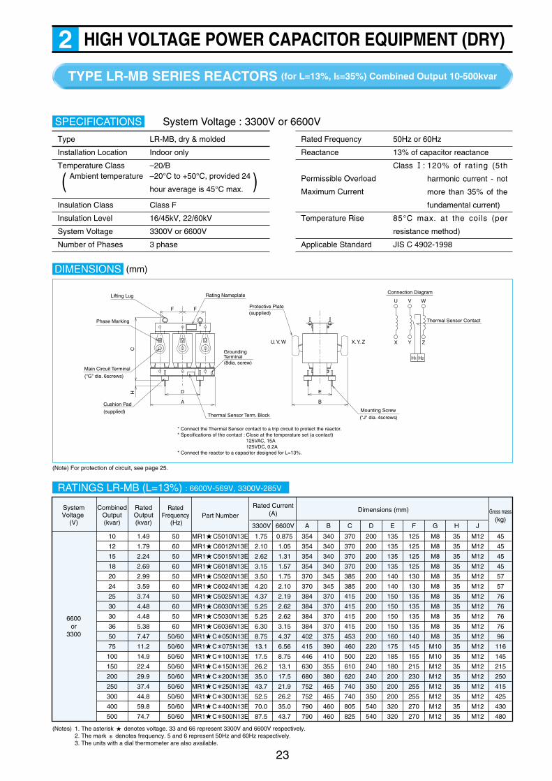
TYPE LR-MB SERIES REACTORS (for L=6%, I5=55%) Combined Output 10-1000kvar
Type LR-MB, dry & molded
Installation Location Indoor only
Temperature Class –20/B
Insulation Class Class F
Insulation Level 16/45kV, 22/60kV
System Voltage 3300V or 6600V
Number of Phases 3 phase
SPECIFICATIONS
Ambient temperature –20°C to +50°C, provided 24
hour average is 45°C max. )(
Rated Frequency 50Hz or 60Hz
Reactance 6% of capacitor reactance
Class @: 130% of rating (5th
harmonic current-not
more than 55% of the
fundamental current)
Temperature Rise 85°C max. at the coils (per
resistance method)
Applicable Standard JIS C 4902-1998
System Voltage : 3300V or 6600V
DIMENSIONS
Thermal Sensor Contact
Connection Diagram
U
X
V
Y
W
Z
H2H1
FF
D
A
Thermal Sensor Term. Block
CH E
B
Main Circuit Terminal
Protective Plate
Lifting Lug Rating Nameplate
Grounding Terminal(8dia. screw)
U. V. W X. Y. Z
("J" dia. 4screws)Mounting screw
Cushion Pad(supplied)
("G" dia. 6screws)
Phase Marking
W V U
* Connect the Thermal Sensor contact to a trip circuit to protect the reactor.
* Specifications of the contact : Close at the temperature set (a contact)125VAC, 15A125VDC, 0.2A
* Connect the reactor to a capacitor designed for L=6%
(supplied)
(Note) For protection of circuit, see page 25.
RATINGS LR-MB (L=6%) : 6600V-243V, 3300V-122V
SystemVoltage
(V)
6600or
3300
CombinedOutput(kvar)
MR1 C5010N26EMR1 C6012N26EMR1 C5015N26EMR1 C6018N26EMR1 C5020N26EMR1 C6024N26EMR1 C5025N26EMR1 C6030N26EMR1 C5030N26EMR1 C6036N26EMR1 C 050N26EMR1 C 075N26EMR1 C 100N26EMR1 C 150N26EMR1 C 200N26EMR1 C 250N26EMR1 C 300N26EMR1 C 400N26EMR1 C 500N26EMR1 C 600N26EMR1 C 700N26EMR1 C 750N26EMR1 C 800N26EMR1 C 900N26EMR1 C 10EN26E
RatedOutput(kvar)
Rated Current(A) Gross mass
(kg)3300V 6600V A B C D E F G H J
Part NumberDimensions (mm)Rated
Frequency (Hz)
1012151820242530303650751001502002503004005006007007508009001000
50605060506050605060
50/6050/6050/6050/6050/6050/6050/6050/6050/6050/6050/6050/6050/6050/6050/60
0.6380.7660.9571.151.281.531.601.911.912.303.194.796.389.5712.816.019.125.531.938.344.747.951.157.463.8
1.752.102.623.153.504.204.375.255.256.308.7513.117.526.235.043.752.570.087.5105122131140157175
0.8751.051.311.571.752.102.192.622.623.154.376.568.7513.117.521.926.235.043.752.561.265.670.078.787.5
322322322322322322354354354354370384402446446630630680752752752752790890890
34343434343446464646577798
145150220220260420420425430480580580
325325325325325325340340340340345370375410410355355380465465465465530580580
340340340340340340370370370370385415453500500610610620740740740740790930930
180180180180180180200200200200200200200220220240240240350350350350540500500
130130130130130130135135135135140150160185185180180200200200200200320360360
115115115115115115125125125125130135140155155215215230255255255255270305305
M8M8M8M8M8M8M8M8M8M8M8M8M8
M10M10M12M12M12M12M12M12M12M12M12M12
35353535353535353535353535353535353535353535353535
M12M12M12M12M12M12M12M12M12M12M12M12M12M12M12M12M12M12M12M12M12M12M12M12M12
(Notes) 1. The asterisk denotes voltage. 33 and 66 represent 3300V and 6600V respectively.2. The mark denotes frequency. 5 and 6 represent 50Hz and 60Hz respectively.3. The units with a dial thermometer (for outdoor or indoor) are also available.4. Class ! reactors (I5=35%) are also available.5. Reactors with I5=70% are also available.
Permissible Overload
Maximum Current
(mm)

TYPE GFC-5 GAS FILLED HIGH VOLTAGE CAPACITORS (for L=13%) Combined Output 10-300kvar
22
HIGH VOLTAGE POWER CAPACITOR EQUIPMENT (DRY)2
System Voltage : 3300V or 6600V
Type GFC-5, gas filled
Installation Location Indoor only
Temperature Class –20/B
Output Tolerance –5% to +15% of rated output
(Unbalance among phases 1.08
or less)
Voltage Withstand T - T : 2 x rated voltage
T - C : 16kV (for 3790V)
22kV (for 7590V)
SPECIFICATIONS
Ambient temperature –20°C to +50°C, provided 24
hour average is 45°C max. )(
Insulation Level 16/45kV, 22/60kV
Dissipation Factor 0.05% max. at 20°C
110% of rating (12 hours max.
per 24 hours)
130% of rating (not including
current due to cap. tol.)
Discharge Resistors Discharge to 50V or less in 5
minutes
Paint Color Munsell 5Y7/1
Applicable Standard JIS C 4902-1998
DIMENSIONS
Connection Diagram
Internal Discharge Resistors
600
140
560538
580545
Trade Mark
DGrounding Terminal8dia. bolt
Instruction Label
Caution Label
Terminal Block
Pressure Switches
Protective Plate
25
153.
2
710
500
875
140 12dia. boltInsulating Cap
Torque Label
Warning Label15x20 2slots Caution Label
480
B
Warning/Caution Label
540
140
500478
520485
Trade Mark
DGrounding Terminal8dia. bolt
Instruction Label
Caution Label
Terminal Block
Pressure Switches
Protective Plate
25
153.
2
710
500
875
140 12dia. boltInsulating Cap
Torque Label
Warning Label
15x20 2slotsCaution Label
420
B
Warning/Caution Label
520
140
480458
500465
Trade Mark
D Grounding Terminal8dia. bolt
Instruction Label
Caution Label
Terminal Block
Pressure Switches
Protective Plate
25
153.
2
710
500
875
140 12dia. boltInsulating Cap
Torque Label
Warning Label15x20 2slots Caution Label
400
BWarning/Caution Label
500
140
480458
Safety Valve
D
Grounding Terminal8dia. bolt
12dia. bolt
Details of Terminal
Instruction Label
Caution Label
Caution Label
Terminal Block
Pressure Switches
Protective Plate
25
15
339
3.2
525 690
140 12dia. boltInsulating Cap
Torque Label
Warning Label Caution Label
400
B
Warning/Caution Label
Fig. 1
Fig. 3
Fig. 2
Fig. 4
Trade Mark
Nameplate
Safety Valve
Nameplate
Safety Valve
Safety Valve
Nameplate
Nameplate
(Note) For protection of circuit, see page 25.
RATINGS GFC-5 (L=13%) 10-300kvar
GF5 CC010R13EGF5 CC015R13EGF5 CC020R13EGF5 CC025R13EGF5 CC030R13EGF5 C5050R13EGF5 C6050R13EGF5 C5075R13EGF5 C6075R13EGF5 C5100R13EGF5 C6100R13EGF5 C5150R13EGF5 C6150R13EGF5 C5200R13EGF5 C6200R13EGF5 C5250R13EGF5 C6250R13EGF5 C5300R13EGF5 C6300R13E
115115115115115
22222325263029535157546764747085809387
B DGross mass
(kg)Fig.Rated Voltage
(V)
7590or
3790
Combined Output(kvar)10/1215/1820/2425/3030/36
11.5/13.817.2/20.723.0/27.628.7/34.534.5/41.4
50
75
100
150
200
250
300
57.5
86.2
115
172
230
287
345
1.75/2.102.62/3.153.50/4.204.37/5.255.25/6.30
0.875/1.051.31/1.571.75/2.102.19/2.622.62/3.15
8.75
13.1
17.5
26.2
35.0
43.7
52.6
4.37
6.56
8.75
13.1
17.5
21.9
26.2
160
180
200
230
250
270
290
7070707070
115
135
155
185
205
225
245
50/6050/6050/6050/6050/60
5060506050605060506050605060
Rated Frequency(Hz)
Rated Output(kvar)
Rated Current (A)3300V 6600V
Part NumberDimensions (mm)
1
2
3
4
(Note) 1. The asterisk denotes voltage. 33 and 66 represent 3300V and 6600V respectively.
Permissible Overloads
Maximum Voltage
Permissible Overloads
Maximum Current
(mm)
23
HIGH VOLTAGE POWER CAPACITOR EQUIPMENT (DRY)2TYPE LR-MB SERIES REACTORS (for L=13%, I5=35%) Combined Output 10-500kvar
Type LR-MB, dry & molded
Installation Location Indoor only
Temperature Class –20/B
Insulation Class Class F
Insulation Level 16/45kV, 22/60kV
System Voltage 3300V or 6600V
Number of Phases 3 phase
SPECIFICATIONS
Ambient temperature –20°C to +50°C, provided 24
hour average is 45°C max. )(
Rated Frequency 50Hz or 60Hz
Reactance 13% of capacitor reactance
Class !: 120% of rating (5th
harmonic current - not
more than 35% of the
fundamental current)
Temperature Rise 85°C max. at the coils (per
resistance method)
Applicable Standard JIS C 4902-1998
DIMENSIONS
Thermal Sensor Contact
Connection Diagram
U
X
V
Y
W
Z
H2H1
W V U
FF
D
A
Thermal Sensor Term. Block
* Connect the Thermal Sensor contact to a trip circuit to protect the reactor.* Specifications of the contact : Close at the temperature set (a contact)
125VAC, 15A125VDC, 0.2A
* Connect the reactor to a capacitor designed for L=13%.
CH E
B
Main Circuit Terminal
Protective Plate
Lifting Lug Rating Nameplate
Grounding Terminal(8dia. screw)
U. V. W X. Y. Z
("J" dia. 4screws)
Mounting ScrewCushion Pad
(supplied)
("G" dia. 6screws)
Phase Marking
(supplied)
RATINGS LR-MB (L=13%) : 6600V-569V, 3300V-285V
SystemVoltage
(V)
6600or
3300
CombinedOutput(kvar)
MR1 C5010N13E
MR1 C6012N13E
MR1 C5015N13E
MR1 C6018N13E
MR1 C5020N13E
MR1 C6024N13E
MR1 C5025N13E
MR1 C6030N13E
MR1 C5030N13E
MR1 C6036N13E
MR1 C 050N13E
MR1 C 075N13E
MR1 C 100N13E
MR1 C 150N13E
MR1 C 200N13E
MR1 C 250N13E
MR1 C 300N13E
MR1 C 400N13E
MR1 C 500N13E
RatedOutput(kvar)
Rated Current(A) Gross mass
(kg)3300V 6600V A B C D E F G H J
Part NumberDimensions (mm)Rated
Frequency (Hz)
10
12
15
18
20
24
25
30
30
36
50
75
100
150
200
250
300
400
500
50
60
50
60
50
60
50
60
50
60
50/60
50/60
50/60
50/60
50/60
50/60
50/60
50/60
50/60
1.49
1.79
2.24
2.69
2.99
3.59
3.74
4.48
4.48
5.38
7.47
11.2
14.9
22.4
29.9
37.4
44.8
59.8
74.7
1.75
2.10
2.62
3.15
3.50
4.20
4.37
5.25
5.25
6.30
8.75
13.1
17.5
26.2
35.0
43.7
52.5
70.0
87.5
0.875
1.05
1.31
1.57
1.75
2.10
2.19
2.62
2.62
3.15
4.37
6.56
8.75
13.1
17.5
21.9
26.2
35.0
43.7
354
354
354
354
370
370
384
384
384
384
402
415
446
630
680
752
752
790
790
45
45
45
45
57
57
76
76
76
76
96
116
145
215
250
415
425
430
480
340
340
340
340
345
345
370
370
370
370
375
390
410
355
380
465
465
460
460
370
370
370
370
385
385
415
415
415
415
453
460
500
610
620
740
740
805
825
200
200
200
200
200
200
200
200
200
200
200
220
220
240
240
350
350
540
540
135
135
135
135
140
140
150
150
150
150
160
175
185
180
200
200
200
320
320
125
125
125
125
130
130
135
135
135
135
140
145
155
215
230
255
255
270
270
M8
M8
M8
M8
M8
M8
M8
M8
M8
M8
M8
M10
M10
M12
M12
M12
M12
M12
M12
35
35
35
35
35
35
35
35
35
35
35
35
35
35
35
35
35
35
35
M12
M12
M12
M12
M12
M12
M12
M12
M12
M12
M12
M12
M12
M12
M12
M12
M12
M12
M12
(Notes) 1. The asterisk denotes voltage. 33 and 66 represent 3300V and 6600V respectively.2. The mark denotes frequency. 5 and 6 represent 50Hz and 60Hz respectively.3. The units with a dial thermometer are also available.
System Voltage : 3300V or 6600V
(Note) For protection of circuit, see page 25.
Permissible Overload
Maximum Current
(mm)
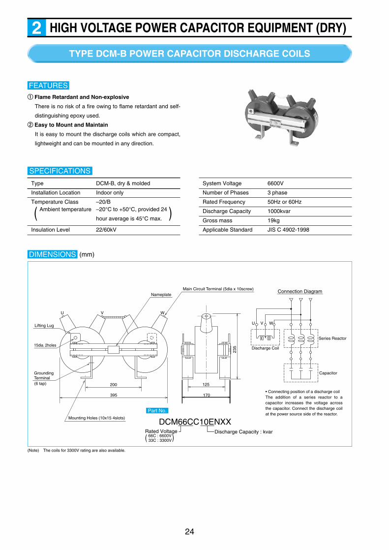
Rated Voltage66C : 6600V33C : 3300V)(
TYPE DCM-B POWER CAPACITOR DISCHARGE COILS
24
HIGH VOLTAGE POWER CAPACITOR EQUIPMENT (DRY)2
qq Flame Retardant and Non-explosive
There is no risk of a fire owing to flame retardant and self-
distinguishing epoxy used.
ww Easy to Mount and Maintain
It is easy to mount the discharge coils which are compact,
lightweight and can be mounted in any direction.
FEATURES
Type DCM-B, dry & molded
Installation Location Indoor only
Temperature Class –20/B
Insulation Level 22/60kV
SPECIFICATIONS
Ambient temperature –20°C to +50°C, provided 24
hour average is 45°C max. )(
System Voltage 6600V
Number of Phases 3 phase
Rated Frequency 50Hz or 60Hz
Discharge Capacity 1000kvar
Gross mass 19kg
Applicable Standard JIS C 4902-1998
DIMENSIONS
Lifting Lug
15dia. 2holes
Grounding Terminal(6 tap) 200
395
Mounting Holes (10x15 4slots)
NameplateMain Circuit Terminal (5dia x 10screw)
125
170
235
U V W
Discharge Coil
Series Reactor
Capacitor
Connection Diagram
• Connecting position of a discharge coilThe addition of a series reactor to a capacitor increases the voltage across the capacitor. Connect the discharge coil at the power source side of the reactor.
U V W
(Note) The coils for 3300V rating are also available.
DCM66CC10ENXXDischarge Capacity : kvar
Part No.
(mm)

Contact Capacity
Arrangement
Operating Temperature
Method
ContactCapacity
Connection
ActivatingPressure
HIGH VOLTAGE POWER CAPACITOR EQUIPMENT (DRY)2
• GAS FILLED CAPACITORSGas filled capacitors are designed to give high
performance and reliability including tight gas seal
capability and self-healing properties by the
implementation of totally sealed construction and
metallized film dielectrics. However, the following
protection schemes are implemented just in case
any failure occurs.
(1) If gas leakage occurs,
The lower pressure limit switch will be activated
when the capacitor’s internal pressure will be
reduced to the ambient pressure. Use the contact
circuit of the pressure switch to give an alarm or
disconnect the capacitor.
The capacitor will not need to be disconnected
immediately after the alarm sounds. However, it is
recommended to disconnect the capacitor within
24 hours.
(2) If the capacitor be internally broken down,
When the internal windings will be broken down,
a fault current will flow and the decomposed gas
will gradually increase the internal pressure.
The upper pressure limit switch will be activated
when the internal pressure reaches the specified
level. Use the contact circuit of the pressure
switch to open a capacitor switching device or a
circuit breaker in the upper stream.
Install current limiting fuses to protect capacitors
from momentary short failure in the capacitor.
Selection of fuses should be made in the same
manner as the oil filled capacitors.
25
PROTECTION OF GAS FILLED HIGH VOLTAGE CAPACITORS & REACTORS
AC 125V 8.0ADC 125V 0.2A
Up–78kPaDown–6kPa
AC 125V 15.0ADC 125V 0.2A
100°C
H1
H2
(normally open)
• SERIES REACTORS
JIS C 4902 specifies that series reactors for powercapacitors shall be operated at a current whichcontains the 5th harmonic current of not more than55% of the fundamental current with the root of thesum of the squares limited to not more than 130% ofthe rated current. If the 5th harmonic voltagedistortion is excessively high, some currentexceeding the limit will flow through the reactorpossibly causing excessive temperature rise to burnout the reactor.The reactors are equipped with a Thermal Sensor todetect excessive temperature rise. Connect thesensor to a circuit breaker (or a switching device)located in the upper stream to disconnect the reactorfrom the power source. Reactors with a dialthermometer is also available as an option.
Protection Method
Thermal Sensor
• Application Notes for Protective ContactsConnect the capacitor fault detectors and the reactorThermal Sensors to the trip circuit of circuit breakersor switching devices. The activation of the abovecontacts to trip the circuit is considered a majorfailure. Consideration should be given to theprotective circuit as shown below to preventreclosing as it is.
Typical Circuit to Prevent Reclosing after Tripped by Protective Contacts
DC100V
E--
E--
E-- 86R
86X 635-52
3-52
86X
52X
52X
52X
52X52
86X
X CC HC
52 : Capacitor Switching Device52X : Auxiliary Relay3-52 : Closing Switch5-52 : Opening Switching
63 : Fault Detector (Capacitor)or Thermal Sensor (Reactor)
86X : Auxiliary Relay86R : Reset Switch
Pressure Up
Pressure Down
13
5
3
5
1
C B2 A1 A2
NC NO

Motor
CapacitoruF
kW 0.1 0.2 0.4 0.75
50Hz 20 20 30 40
Max. Input(kVA)
3 min.
Capacitor uF
5 min. 7.5 min. 10 min. 15 min. 20 min. 25 min. 30 min. 35 min. 40 min.45 min.below 50
Motor
CapacitoruF
kW 0.75 1.5 2.2 3.7 5.5 7.5 11 15 19 22 30 37 55
50Hz 7.5 10 15 20 30 40 50 75 75 100 125 150 250
Motor
CapacitoruF
kW 0.2 0.4 0.75 1.5 2.2 3.7 5.5 7.5 11 15 19 22 30 37 55
50Hz 15 20 30 40 50 75 100 150 200 250 300 400 500 600 900
TYPE N2 (200V) & E (200V, 400V) LOW VOLTAGE POWER CAPACITORS
26
LOW VOLTAGE POWER CAPACITOR EQUIPMENT3
Shizuki Low Voltage Power Capacitors are the most economical means to save electrical power.
qq Electric Power Bills Are Reduced.
The installation of power factor correction capacitors will
raise the power factor. For a higher power factor attained
by users, lower electrical charges are generally offered by
utility companies.
ww Equipment Cost Is Reduced.
When power factor capacitors are added to new
installation of plant equipment including welding machines
that draw a high current, they will not only improve a power
factor but also reduce a line current, saving the cost for
distribution equipment.
BENEFITSee Productivity Is Improved and Quality Becomes Consistent.
Power factor correction will help raise the voltage across a
motor, increasing rotation torque and reduce voltage
fluctuation, keeping consistent speed. Hence, productivity
will be increased and quality will become consistent.
rr System Capacity Is Gained.
Improved power factor reduces line current. Power factor
correction capacitors will relieve the capacity of distribution
equipment (transformers, switching devices), and
installation of the capacitors will enable new loads to be
added without increasing the capacity of the existing
distribution equipment.STANDARD CAPACITOR OUTPUT
qq Induction Motors (a) 200V 3 Phase Motors
HP 1/4 1/2 1 2 3 5 7.5 10 15 20 25 30 40 50 75
60Hz 10 15 20 30 40 50 75 100 150 200 250 300 400 500 750
HP 1/8 1/4 1/2 1
60Hz 20 20 20 30
(b) 200V 1 Phase Motors
(c)400V 3Phase Motors
ww AC Arc Welders 200V
HP 1 2 3 5 7.5 10 15 20 25 30 40 50 75
60Hz 5 7.5 10 15 20 30 40 50 75 75 100 125 200
100 150 200 250 300 400 500 600 700 800 900
Do not place the capacitors at the following locations.
qq where rain or water drop falls
ww where there is heavy iron powder or dust
ee areas with high relative humidity
rr area with corrosive gases
APPLICATION NOTES
(Note) The same capacitance applies to 50Hz and 60Hz. Use a capacitor with 50% of the above capacitance for AC resistance welders and DC arc welders.
tt where condensation of humidity occurs
yy where salt damage is expected
uu where vibration occurs
ii where the ambient temperature is not within –25°C to
+45°C and direct sunlight is present
TYPE E
TYPE N2
TYPE E

LOW VOLTAGE POWER CAPACITOR EQUIPMENT3
q When installing two or more capacitors at the same
location, secure the spacing between units of 25mm or
more. For capacitors rated at 20kvar or more (220V &
400V), the spacing should be 50mm or more.
* Type N2 does not require
INSTALLATION WORKS
w Ensure to fasten the screws to connect cables.
e Do not mount type E holizontally
r Ground type E capacitors using the grounding terminal.
27
To switch off an apparatus to which a capacitor is connected, be
sure to disconnect the capacitor from the power source at the same
SWITCHING OF CAPACITORStime. If the capacitor remains connected to power source, the
power source as well as the capacitor would be affected adversely.
The capacitors have an internal protective device. Should a
failure (breakdown of the internal windings) occurs in the
capacitor, the protective device will activate to disconnect the
PROTECTIVE DEVICEcapacitor from the line. Be sure to replace the falied capacitor
with a new one.
Wrong wiring of low voltage capacitor to an induction motor
with a star-delta starter would cause the capacitor to
breakdown. Be sure to do the correct wiring as shown below.
Correct Wiring
Z
Capacitor
Induction Motor
Y–
V
U
Y
X
Starter
Power Source
Power Switch W
Wrong Wiring
Z
Capacitor
Induction Motor
Induction Motor with Y– Starter
Y–
V
U
Y
X
Starter
Power Source
Power Switch W
TYPE N2
q Idea for mounting in a panel. The capacitors can be
mounted on a 35mm rail per IEC easily to save labor.
w Can be mounted in any directions.
e Provides a high safety due to dry type not using oil and
internal protective device.
FEATURESTYPE E
q Smaller by 15-30% than our conventional design due to the
low loss dielectrics used.
w Enhanced reliability for connection due to the quick-
connect terminal blocks used.
Type N2 & E
Installation Location Indoor only, altitude : 2000m max.
Ambient temperature –25°C to +45°C (24 hour average : 35°C
max., annual average : 25°C max.)
Output Tolerance –5% to +15% of rated output
(Unbalance among phases 1.08
or less)
Voltage Withstand T - T : 2.15 x rated voltage for 2 seconds
T - C : 3000V for 10 seconds (Type E)
Dissipation Factor 0.12% max. at 20°C
SPECIFICATIONS
110% of rating (8 hours max. per 24 hours)
115% of rating (30 minutes max. per 24 hours)
120% of rating (5 minutes max.)
130% of rating (1 minute max.)
overvoltage exceeding 115% : 200 times max.
130% max. of rating
Discharge Resistors Discharge to 75V or less in 3 minutes
Safety Test Per para. 8.12 of JIS C 4901
Paint Color Munsell 5Y7/1 (Type E)
Applicable Standard JIS C 4901-2000
System Voltage : 200VuF
• TYPE N2 (200V), TYPE E(200V)
CONNECTION TO INDUCTION MOTORS WITH A STAR-DELTA STARTER
Permissible Overloads
Maximum Voltage
Maximum Current
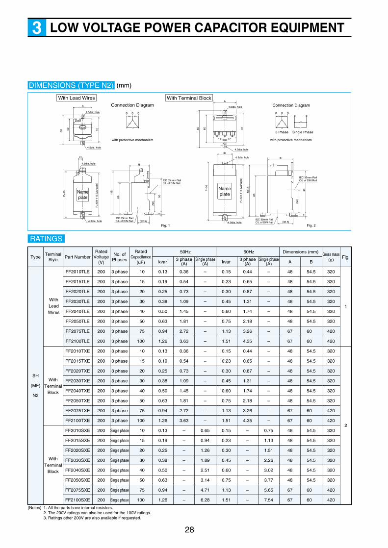
28
LOW VOLTAGE POWER CAPACITOR EQUIPMENT3
DIMENSIONS (TYPE N2)
A
4.5dia. hole
4.5dia. hole
4.5dia. hole
4.5dia. hole
80
60 70
A
4.5dia. hole
4.5dia. hole
80 60 70
with protective mechanism
12
P+
10
P+
10
B
IEC 35mm RailC/L of DIN Rail
IEC 35 mm RailC/L of DIN Rail
Fig. 1 Fig. 2
907
(50)
(32.5)
115
86
Nameplate
4.5dia. hole
30
Nameplate
B
907
(50)
(32.5)
108.
5
86
Single Phase3 Phase
Connection Diagram
with protective mechanism
Connection Diagram
With Lead Wires With Terminal Block
IEC 35mm RailC/L of DIN Rail
IEC 35mm RailC/L of DIN Rail
4.5dia. hole
P=
104-
115
(var
iabl
e)
P=
104-
115
(var
iabl
e)RATINGS
Type Part Number
FF2010TLE
FF2015TLE
FF2020TLE
FF2030TLE
FF2040TLE
FF2050TLE
FF2075TLE
FF2100TLE
FF2010TXE
FF2015TXE
FF2020TXE
FF2030TXE
FF2040TXE
FF2050TXE
FF2075TXE
FF2100TXE
FF2010SXE
FF2015SXE
FF2020SXE
FF2030SXE
FF2040SXE
FF2050SXE
FF2075SXE
FF2100SXE
200
200
200
200
200
200
200
200
200
200
200
200
200
200
200
200
200
200
200
200
200
200
200
200
3 phase
3 phase
3 phase
3 phase
3 phase
3 phase
3 phase
3 phase
3 phase
3 phase
3 phase
3 phase
3 phase
3 phase
3 phase
3 phase
Single phase
Single phase
Single phase
Single phase
Single phase
Single phase
Single phase
Single phase
10
15
20
30
40
50
75
100
10
15
20
30
40
50
75
100
10
15
20
30
40
50
75
100
0.13
0.19
0.25
0.38
0.50
0.63
0.94
1.26
0.13
0.19
0.25
0.38
0.50
0.63
0.94
1.26
0.13
0.19
0.25
0.38
0.50
0.63
0.94
1.26
0.36
0.54
0.73
1.09
1.45
1.81
2.72
3.63
0.36
0.54
0.73
1.09
1.45
1.81
2.72
3.63
–
–
–
–
–
–
–
–
–
–
–
–
–
–
–
–
–
–
–
–
–
–
–
–
0.65
0.94
1.26
1.89
2.51
3.14
4.71
6.28
0.15
0.23
0.30
0.45
0.60
0.75
1.13
1.51
0.15
0.23
0.30
0.45
0.60
0.75
1.13
1.51
0.15
0.23
0.30
0.45
0.60
0.75
1.13
1.51
0.44
0.65
0.87
1.31
1.74
2.18
3.26
4.35
0.44
0.65
0.87
1.31
1.74
2.18
3.26
4.35
–
–
–
–
–
–
–
–
–
–
–
–
–
–
–
–
–
–
–
–
–
–
–
–
0.75
1.13
1.51
2.26
3.02
3.77
5.65
7.54
48
48
48
48
48
48
67
67
48
48
48
48
48
48
67
67
48
48
48
48
48
48
67
67
54.5
54.5
54.5
54.5
54.5
54.5
60
60
54.5
54.5
54.5
54.5
54.5
54.5
60
60
54.5
54.5
54.5
54.5
54.5
54.5
60
60
1
2
No. ofPhases
Gross mass(g)
RatedVoltage
(V)
TerminalStyle
RatedCapacitance
(uF) kvar3 phase
(A)
50Hz
Single phase(A) kvar
3 phase(A)
60Hz Dimensions (mm)
Single phase(A) A B
320
320
320
320
320
320
420
420
320
320
320
320
320
320
420
420
320
320
320
320
320
320
420
420
Fig.
SH
(MF)
N2
WithLeadWires
WithTerminal
Block
WithTerminal
Block
(Notes) 1. All the parts have internal resistors.2. The 200V ratings can also be used for the 100V ratings.3. Ratings other 200V are also available if requested.
(mm)
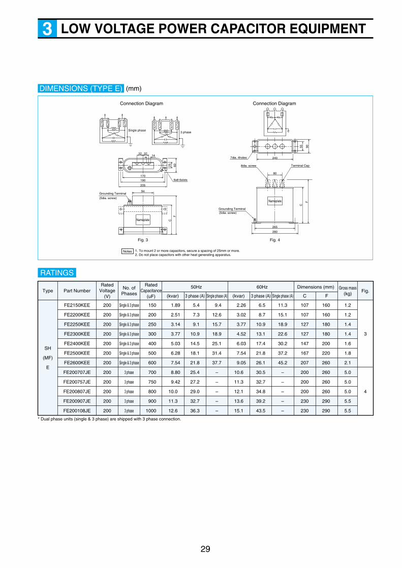
29
LOW VOLTAGE POWER CAPACITOR EQUIPMENT3
DIMENSIONS (TYPE E)
Single phase3 phase
32 3214
170190
205
94
Nameplate
Nameplate
Fig. 3 Fig. 4
Connection DiagramConnection Diagram
6025
6x8 6slots
Grounding Terminal
(5dia. screw)
C
F
C
F
7dia. 4holes
55 90
240
80
265
280
8dia. screw Terminal Cap
Grounding Terminal(5dia. screw)
1. To mount 2 or more capacitors, secure a spacing of 25mm or more.2. Do not place capacitors with other heat generating apparatus.
Notes
RATINGS
Type Part Number
FE2150KEE
FE2200KEE
FE2250KEE
FE2300KEE
FE2400KEE
FE2500KEE
FE2600KEE
FE200707JE
FE200757JE
FE200807JE
FE200907JE
FE200108JE
200
200
200
200
200
200
200
200
200
200
200
200
Single & 3 phase
Single & 3 phase
Single & 3 phase
Single & 3 phase
Single & 3 phase
Single & 3 phase
Single & 3 phase
3 phase
3 phase
3 phase
3 phase
3 phase
150
200
250
300
400
500
600
700
750
800
900
1000
1.89
2.51
3.14
3.77
5.03
6.28
7.54
8.80
9.42
10.0
11.3
12.6
5.4
7.3
9.1
10.9
14.5
18.1
21.8
25.4
27.2
29.0
32.7
36.3
6.5
8.7
10.9
13.1
17.4
21.8
26.1
30.5
32.7
34.8
39.2
43.5
9.4
12.6
15.7
18.9
25.1
31.4
37.7
–
–
–
–
–
2.26
3.02
3.77
4.52
6.03
7.54
9.05
10.6
11.3
12.1
13.6
15.1
11.3
15.1
18.9
22.6
30.2
37.2
45.2
–
–
–
–
–
107
107
127
127
147
167
207
200
200
200
230
230
160
160
180
180
200
220
260
260
260
260
290
290
1.2
1.2
1.4
1.4
1.6
1.8
2.1
5.0
5.0
5.0
5.5
5.5
3
4
No. ofPhases
RatedVoltage
(V)
RatedCapacitance
(uF) (kvar) 3 phase (A)
50Hz
Single phase (A) (kvar) 3 phase (A)
60Hz Dimensions (mm)
Single phase (A) C FFig.
Gross mass(kg)
SH
(MF)
E
* Dual phase units (single & 3 phase) are shipped with 3 phase connection.
(mm)

30
LOW VOLTAGE POWER CAPACITOR EQUIPMENT3
RATINGS (400V-460V, 50/60Hz)
Part Number
Rated Current (A)
50Hz
400V
60Hz
RG2460505 JE
RG2460755 JE
RG2460106 JE
RG2460156 JE
RG2460206 JE
RG2460256 JE
RG2460306 JE
RG2460406 JE
RG2460506 JE
RG2460756 JE
RG2460107 JE
RG2460137 JE
RG2460157 JE
RG2460207 JE
RG2460257 JE
5
7.5
10
15
20
25
30
40
50
75
100
125
150
200
250
0.36
0.54
0.73
1.09
1.45
1.81
2.18
2.90
3.63
5.44
7.26
9.07
10.9
14.5
18.1
80
80
100
100
100
100
100
120
120
150
180
210
210
270
270
105
105
125
125
125
125
125
145
145
175
205
235
235
295
295
1
2
RatedCapacitance
(uF)
Dimensions(mm)
C F
Fig.
0.38
0.56
0.75
1.13
1.51
1.88
2.26
3.01
3.76
5.65
7.53
9.41
11.3
15.1
18.8
415V
0.40
0.60
0.80
11.20
1.60
2.00
2.39
3.19
3.99
5.99
7.98
9.98
12.0
16.0
20.0
440V 460V
0.42
0.63
0.83
1.25
1.67
2.09
2.50
3.34
4.17
6.26
8.34
10.4
12.5
16.7
20.9
0.44
0.65
0.87
1.31
1.74
2.18
2.61
3.48
4.35
6.53
8.71
10.9
13.1
17.4
21.8
0.45
0.68
0.90
1.35
1.81
2.26
2.71
3.61
4.52
6.77
9.03
11.3
13.5
18.1
22.6
0.49
0.72
0.96
1.44
1.92
2.39
2.87
3.83
4.79
7.18
9.58
12.0
14.4
19.2
23.9
0.50
0.75
1.00
1.50
2.00
2.50
3.00
4.00
5.01
7.51
10.0
12.5
15.0
20.0
25.0
400V 415V 440V 460V
1.1
1.1
1.3
1.3
1.3
1.3
1.3
1.6
1.6
1.9
2.3
3.5
3.5
4.5
4.5
Gross mass(kg)
Type RG-2
Installation Location Indoor only, altitude : 2000m max.
Ambient temperature –25°C to +45°C (24 hour average : 35°C
max., annual average : 25°C max.)
Output Tolerance –5% to +15% of rated output
(Unbalance among phases 1.08
or less)
Voltage Withstand T - T : 2.15 x rated voltage for 2 seconds
T - C : 3000V for 10 seconds (Type E)
Dissipation Factor 0.2% max. at 20°C
110% of rating (8 hours max. per 24 hours)
115% of rating (30 minutes max. per 24 hours)
120% of rating (5 minutes max. )
130% of rating (1 minute max.)
overvoltage exceeding 115% : 200 times max.
130% max. of rating
Discharge Resistors Discharge to 75V or less in 3 minutes
Safety Test Per para. 8.12 of JIS C 4901
Paint Color Munsell 5Y7/1
Applicable Standard JIS C 4901-2000
DIMENSIONS (TYPE N2)
130
3030
7dia. 4holes
5dia. bolt
3030 5dia. boltTorque Nameplate
Torque NameplateGrounding Terminal5dia screw(3.5dia. hole)
Fig. 1 Fig. 2
Grounding Terminal5dia. screw(3.5dia. hole)
40F
C
FC
70
t 1.0
t 1.0
150165
1737dia. 4holes
4070
190205
Marking
Marking
Connection Diagram
with internal resistors
SPECIFICATIONS System Voltage : 400VuF
Permissible Overloads
Maximum Voltage
Maximum Current
(mm)
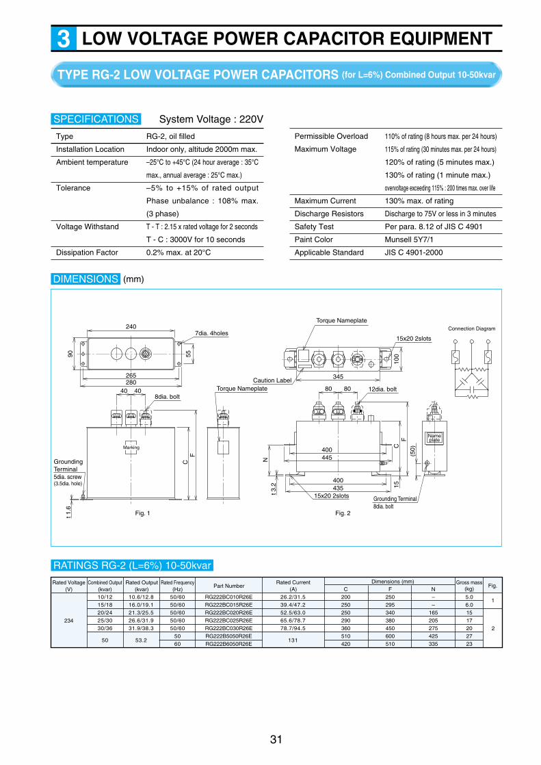
LOW VOLTAGE POWER CAPACITOR EQUIPMENT3
31
TYPE RG-2 LOW VOLTAGE POWER CAPACITORS (for L=6%) Combined Output 10-50kvar
Type RG-2, oil filled
Installation Location Indoor only, altitude 2000m max.
Ambient temperature –25°C to +45°C (24 hour average : 35°C
max., annual average : 25°C max.)
Tolerance –5% to +15% of rated output
Phase unbalance : 108% max.
(3 phase)
Voltage Withstand T - T : 2.15 x rated voltage for 2 seconds
T - C : 3000V for 10 seconds
Dissipation Factor 0.2% max. at 20°C
SPECIFICATIONS
110% of rating (8 hours max. per 24 hours)
115% of rating (30 minutes max. per 24 hours)
120% of rating (5 minutes max.)
130% of rating (1 minute max.)
overvoltage exceeding 115% : 200 times max. over life
Maximum Current 130% max. of rating
Discharge Resistors Discharge to 75V or less in 3 minutes
Safety Test Per para. 8.12 of JIS C 4901
Paint Color Munsell 5Y7/1
Applicable Standard JIS C 4901-2000
System Voltage : 220V
DIMENSIONS
240
4040 8080
7dia. 4holes
8dia. boltTorque Nameplate
Caution Label
Torque Nameplate
15x20 2slots
12dia. bolt
Grounding Terminal5dia. screw(3.5dia. hole)
Fig. 1 Fig. 2
55
100
FC
15
345
400445
400
Nameplate
15x20 2slots435
FC
90
N
(50)
Grounding Terminal8dia. bolt
t 3.2
t 1.6
265280
Connection Diagram
Marking
RG222BC010R26ERG222BC015R26ERG222BC020R26ERG222BC025R26ERG222BC030R26ERG222B5050R26ERG222B6050R26E
200250250290360510420
5.06.01517202723
CGross mass
(kg)Fig.Rated Voltage
(V)
234
Combined Output(kvar)10/1215/1820/2425/3030/36
10.6/12.816.0/19.121.3/25.526.6/31.931.9/38.3
50 53.2
26.2/31.539.4/47.252.5/63.065.6/78.778.7/94.5
131
250295340380450600510
F––
165205275425335
N50/6050/6050/6050/6050/60
5060
Rated Frequency(Hz)
Rated Output(kvar)
Rated Current(A)
Part NumberDimensions (mm)
1
2
RATINGS RG-2 (L=6%) 10-50kvar
Permissible Overload
Maximum Voltage
(mm)
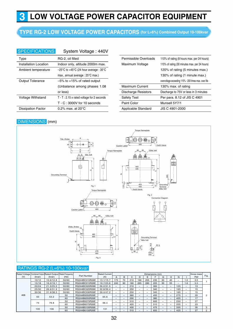
32
LOW VOLTAGE POWER CAPACITOR EQUIPMENT3TYPE RG-2 LOW VOLTAGE POWER CAPACITORS (for L=6%) Combined Output 10-100kvar
DIMENSIONS
8080
Caution Label
Torque Nameplate
12dia. bolt
Fig. 3
130
FC
420
485520
478
Nameplate
15x20 2slots
25dia. 2holes
50285 478
502
N
(70)
Grounding Terminal
8dia. bolt
R7.538
1~3
8080
Caution Label
Torque Nameplate
12dia. bolt
100
FC
15
345
400445
400
Nameplate
15x20 2slots
15x20 2slots
435
(50)
N
GroundingTerminal8dia. bolt
Connection Diagram
t 3.2
A
GG
7dia. 4holes
5dia. bolt
Torque Nameplate
Fig. 1
Fig. 2
Grounding Terminal
HF
C
Bt
DE
t4.5
Marking
RG244BC010R26ERG244BC015R26ERG244BC020R26ERG244BC025R26ERG244BC030R26ERG244B5050R26ERG244B6050R26ERG244B5075R26ERG244B6075R26ERG244B5100R26ERG244B6100R26E
3.55.5131515201727233527
AGross mass
(kg) Fig.Rated Voltage
(V)
468
Combined Output(kvar)
10/1215/1820/2425/3030/36
10.6/12.816.0/19.121.3/25.526.6/31.931.9/38.3
50
75
100
53.2
79.8
106
13.1/15.719.7/23.626.2/31.532.8/39.439.4/47.2
65.6
98.4
131
173240–––––––––
B7090–––––––––
C210180210250250360290510420400510
D190265–––––––––
E205280–––––––––
F235205300340340450380600510475600
G3030–––––––––
H4055–––––––––
N––
125165165275425250205335425
t1.01.6–––––––––
50/6050/6050/6050/6050/60
506050605060
Rated Frequency(Hz)
Rated Output(kvar)
Rated Current(A)Part Number
Dimensions (mm)
1
2
32
RATINGS RG-2 (L=6%) 10-100kvar
Type RG-2, oil filled
Installation Location Indoor only, altitude 2000m max.
Ambient temperature –25°C to +45°C (24 hour average : 35°C
max., annual average : 25°C max.)
Output Tolerance –5% to +15% of rated output
(Unbalance among phases 1.08
or less)
Voltage Withstand T - T : 2.15 x rated voltage for 2 seconds
T - C : 3000V for 10 seconds
Dissipation Factor 0.2% max. at 20°C
SPECIFICATIONS
110% of rating (8 hours max. per 24 hours)
115% of rating (30 minutes max. per 24 hours)
120% of rating (5 minutes max.)
130% of rating (1 minute max.)
overvoltage exceeding 115% : 200 times max. over life
Maximum Current 130% max. of rating
Discharge Resistors Discharge to 75V or less in 3 minutes
Safety Test Per para. 8.12 of JIS C 4901
Paint Color Munsell 5Y7/1
Applicable Standard JIS C 4901-2000
System Voltage : 440V
Permissible Overloads
Maximum Voltage
(mm)
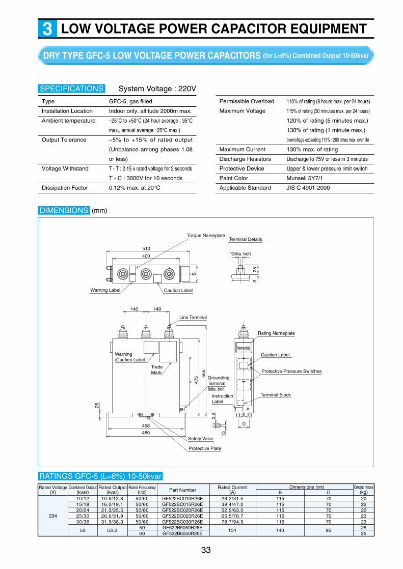
33
LOW VOLTAGE POWER CAPACITOR EQUIPMENT3DRY TYPE GFC-5 LOW VOLTAGE POWER CAPACITORS (for L=6%) Combined Output 10-50kvar
DIMENSIONS
510
140
480
458
Safety Valve
Warning/Caution Label
Trade Mark
D
GroundingTerminal8dia. bolt
12dia. bolt
Terminal Details
InstructionLabel
Caution Label
Rating Nameplate
Terminal Block
Protective Pressure Switches
Protective Plate
25
15
325
3.2
475 55
5
140
Line Terminal
Torque Nameplate
Warning Label Caution Label
400
B
Nameplate
GF522BC010R26EGF522BC015R26EGF522BC020R26EGF522BC025R26EGF522BC030R26EGF522B5050R26EGF522B6050R26E
115115115115115
20222223232525
B7070707070
DGross mass
(kg)Rated Voltage
(V)
234
Combined Output(kvar)10/1215/1820/2425/3030/36
10.6/12.816.0/19.121.3/25.526.6/31.931.9/38.3
50 53.2
26.2/31.539.4/47.252.5/63.065.5/78.778.7/94.5
131 140 95
50/6050/6050/6050/6050/60
5060
Rated Frequency(Hz)
Rated Output(kvar)
Rated Current(A)Part Number
Dimensions (mm)
RATINGS GFC-5 (L=6%) 10-50kvar
Type GFC-5, gas filled
Installation Location Indoor only, altitude 2000m max.
Ambient temperature –25°C to +50°C (24 hour average : 35°C
max., annual average : 25°C max.)
Output Tolerance –5% to +15% of rated output
(Unbalance among phases 1.08
or less)
Voltage Withstand T - T : 2.15 x rated voltage for 2 seconds
T - C : 3000V for 10 seconds
Dissipation Factor 0.12% max. at 20°C
SPECIFICATIONS
110% of rating (8 hours max. per 24 hours)
115% of rating (30 minutes max. per 24 hours)
120% of rating (5 minutes max.)
130% of rating (1 minute max.)
overvoltage exceeding 115% : 200 times max. over life
Maximum Current 130% max. of rating
Discharge Resistors Discharge to 75V or less in 3 minutes
Protective Device Upper & lower pressure limit switch
Paint Color Munsell 5Y7/1
Applicable Standard JIS C 4901-2000
System Voltage : 220V
Permissible Overload
Maximum Voltage
(mm)
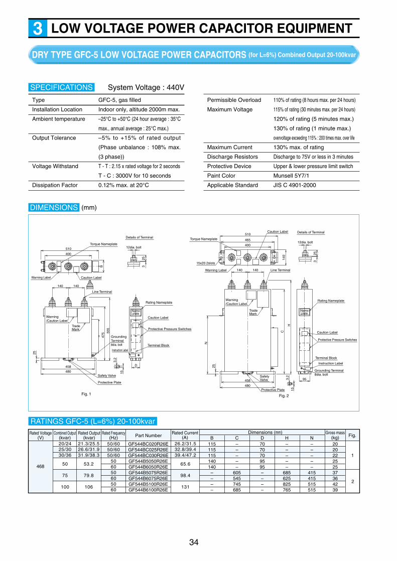
DRY TYPE GFC-5 LOW VOLTAGE POWER CAPACITORS (for L=6%) Combined Output 20-100kvar
34
LOW VOLTAGE POWER CAPACITOR EQUIPMENT3
DIMENSIONS
510
140
480458
Safety Valve
Warning/Caution Label
Trade Mark
D
Grounding Terminal8dia. bolt
12dia. bolt
Details of Terminal
Fig. 2Fig. 1
Instruction Label
Caution Label
Rating Nameplate
Nameplate
Terminal Block
Protective Pressure Switches
Protective Plate
25
15
325
3.2
475 55
5
140
Line Terminal
Torque Nameplate
Warning Label Caution Label
400
B
510
140
480
458Safety Valve
Warning/Caution Label
Trade Mark
12dia. bolt
Details of Terminal
Caution Label
Rating Nameplate
Nameplate
Terminal Block
Grounding Terminal8dia. bolt
Protective Pressure Switches
Protective Plate
25
15
325
3.2
C
H
N
140 Line Terminal
Torque Nameplate
Warning Label
15x20 2slots
Caution Label
465
400
140
95
Instruction Label
GF544BC020R26EGF544BC025R26EGF544BC030R26EGF544B5050R26EGF544B6050R26EGF544B5075R26EGF544B6075R26EGF544B5100R26EGF544B6100R26E
202022252537364239
BGross mass
(kg) Fig.Rated Voltage(V)
468
Combined Output(kvar)20/2425/3030/36
21.3/25.526.6/31.931.9/38.3
50
75
100
53.2
79.8
106
26.2/31.532.8/39.439.4/47.2
65.6
98.4
131
115115115140140––––
C–––––
605545745685
D7070709595––––
H–––––
685625825765
N–––––
415415515515
50/6050/6050/60
506050605060
Rated Frequency(Hz)
Rated Output(kvar)
Rated Current(A)Part Number
Dimensions (mm)
1
2
RATINGS GFC-5 (L=6%) 20-100kvar
Type GFC-5, gas filled
Installation Location Indoor only, altitude 2000m max.
Ambient temperature –25°C to +50°C (24 hour average : 35°C
max., annual average : 25°C max.)
Output Tolerance –5% to +15% of rated output
(Phase unbalance : 108% max.
(3 phase))
Voltage Withstand T - T : 2.15 x rated voltage for 2 seconds
T - C : 3000V for 10 seconds
Dissipation Factor 0.12% max. at 20°C
SPECIFICATIONS
Permissible Overload 110% of rating (8 hours max. per 24 hours)
Maximum Voltage 115% of rating (30 minutes max. per 24 hours)
120% of rating (5 minutes max.)
130% of rating (1 minute max.)
overvoltage exceeding 115% : 200 times max. over life
Maximum Current 130% max. of rating
Discharge Resistors Discharge to 75V or less in 3 minutes
Protective Device Upper & lower pressure limit switch
Paint Color Munsell 5Y7/1
Applicable Standard JIS C 4901-2000
System Voltage : 440V
(mm)

35
LOW VOLTAGE POWER CAPACITOR EQUIPMENT3TYPE DR-1 SERIES REACTORS (for L=6%, I5=55%) Combined Output 10-300kvar
DIMENSIONS
BC
G HX ZY
U W
Thermal Sensor Contact
V
H1 H2
Thermal Sensor Term. Block
(2P-3.5dia. screw)Thermal Sensor Term. Block
(2P-3.5dia. screw)
Grounding Terminal
(6dia. screw) Grounding Terminal
(6dia. screw)("L"dia. 4holes)
Main Circuit Terminal("J"dia. 6screws)
Lifting holes("K"dia. 2holes)
Lifting holes
("K"dia. 2holes)
A
Mounting holes
("L"dia. 4holes)Mounting holes
D E
F
G G GG
Rating Nameplate
Connection Diagram
U X V Y W Z
Details of Main Circuit Terminal
Fig. 2Fig. 1
A
D E
14dia. hole tM50
2510
5
130
F
H
Rating Nameplate
Main Circuit Terminal
BC
G G G G G
U X V Y W Z
10121518202425303036507575100100150150200250300
50605060506050605060
50/6050/6050/6050/6050/6050/6050/6050/6050/6050/60
0.6380.7660.9571.151.281.531.601.911.912.303.194.794.796.386.389.579.5712.816.019.1
26.231.539.447.252.563.065.678.778.794.5131197–
262–
394––––
13.115.719.723.626.231.532.839.439.447.265.6
–98.4
–131–
197262328394
210210210250250270270270270320320450320450380450450450450470
1212161619212325263035454567679898
130145170
DR1 B5010N26EDR1 B6012N26EDR1 B5015N26EDR1 B6018N26EDR1 B5020N26EDR1 B6024N26EDR1 B5025N26EDR1 B6030N26EDR1 B5030N26EDR1 B6036N26EDR1 B 050N26EDR122B 075N26EDR144B 075N26EDR122B 100N26EDR144B 100N26EDR122B 150N26EDR144B 150N26EDR144B 200N26EDR144B 250N26EDR144B 300N26E
220V 440V A
150150150170170180180180180200200240240250250260260270280300
B
200200200240240280280280280330330435360475400535535545555645
C
707070808090909090
100100100100200200200200250300300
D
959595
100100100110110110120120150150150150160160170170180
E
125125125130130130140140140160160190190200200200200200200220
F
3535353535353535355050755075607575757575
G
909090
100100100100100100120120140140150150150150160160200
H
M8M8M8M8M8M8M8M8M8
M10M10
–M10
–M12
–––––
J
1616162020202020202525252525252525252525
K
1010101010101010101212121212121212121212
L
–––––––––––6–6–86688
M 220V
1 1
2 2
440V
SystemVoltage
(V)
220or
440
CombinedOutput(kvar)
RatedOutput(kvar)
Rated Current(A)Part Number
Dimensions (mm)RatedFrequency
(Hz)
Gross mass(kg)
Fig.
(Notes) 1. The asterisk denotes voltage. 22 and 44 represent 220V and 440V respectively.2. The mark denotes frequency. 5 and 6 represent 50Hz and 60Hz respectively.3. Class ! reactors (I5=35%) are also available.4. Reactors with I5=70% are also available.
RATINGS DR-1 (L=6%) Rated Voltage : 220V-8.11V, 440V-16.2V
Type DR-1, dry type
Installation Location Indoor only, altitude : 2000m max.
Ambient temperature –20°C to +45°C (24 hour average : 35°C
max., annual average : 25°C max.)
Insulation Class Class H
System Voltage 220V or 440V
Number of Phases 3 phase
SPECIFICATIONS
Rated Frequency 50Hz or 60Hz
Reactance 6% of capacitor reactance
130% of rating (5th harmonic current - not
more than 55% of the fundamental current)
Temperature Rise 115°C max. at the coils (per
resistance method)
Applicable Standard JIS C 4901-2000
System Voltage : 220V or 440V
Permissible Overload
Maximum Current
(mm)
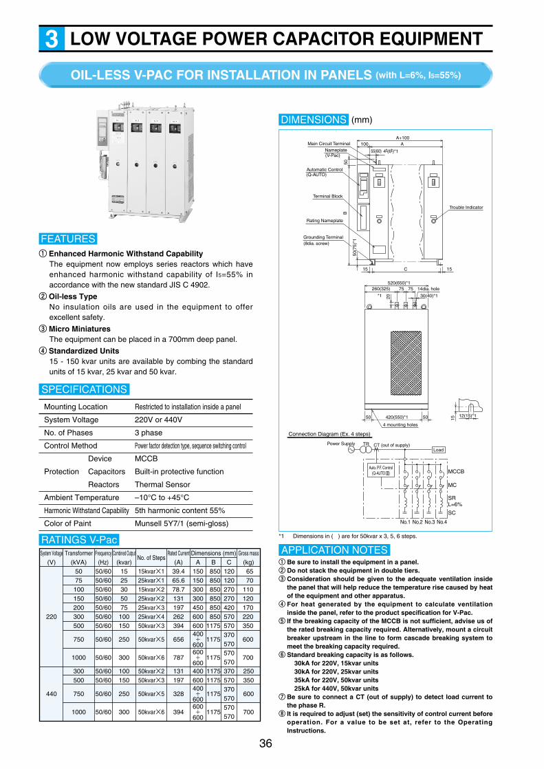
OIL-LESS V-PAC FOR INSTALLATION IN PANELS (with L=6%, I5=55%)
36
LOW VOLTAGE POWER CAPACITOR EQUIPMENT3
qq Enhanced Harmonic Withstand CapabilityThe equipment now employs series reactors which haveenhanced harmonic withstand capability of I5=55% inaccordance with the new standard JIS C 4902.
ww Oil-less TypeNo insulation oils are used in the equipment to offerexcellent safety.
ee Micro MiniaturesThe equipment can be placed in a 700mm deep panel.
rr Standardized Units15 - 150 kvar units are available by combing the standardunits of 15 kvar, 25 kvar and 50 kvar.
FEATURES
Mounting Location Restricted to installation inside a panel
System Voltage 220V or 440V
No. of Phases 3 phase
Control Method Power factor detection type, sequence switching control
Device MCCB
Protection Capacitors Built-in protective function
Reactors Thermal Sensor
Ambient Temperature –10°C to +45°C
Harmonic Withstand Capability 5th harmonic content 55%
Color of Paint Munsell 5Y7/1 (semi-gloss)
SPECIFICATIONS
DIMENSIONS
Connection Diagram (Ex. 4 steps)
Power Supply TR CT (out of supply)
Auto. P.F. Control(Q-AUTO )
Load
MCCB
MC
SC
SRL=6%
No.1 No.2 No.3 No.4
Main Circuit TerminalNameplate
Rating Nameplate
(V-Pac)
Automatic Control(Q-AUTO)
Terminal Block
Grounding Terminal
100 AA+100
55(60) 4t(6t)*1
50B
15 15C
Trouble Indicator
520(650)*1260(325) 75 75 14dia. hole
20
50 420(550)*1 50
4 mounting holes
15
50(7
5)*1
30(40)*1*1
12(15)*1
(8dia. screw)
*1 Dimensions in ( ) are for 50kvar x 3, 5, 6 steps.RATINGS V-PacSystem Voltage
(V)Transformer
(kVA)Frequency(Hz)
Combined Output(kvar)
No. of StepsRated Current
(A)Dimensions (mm)
A B CGross mass
(kg)
220
5075100150200300500
750
1000
50/6050/6050/6050/6050/6050/6050/60
50/60
50/60
1525305075100150
250
300
15kvar×125kvar×115kvar×225kvar×225kvar×325kvar×450kvar×3
50kvar×5
50kvar×6
39.465.678.7131197262394
656
787
150150300300450600600400
600600
600
850850850850850850
1175
1175
1175
120120270270420570570370570570570
6570
110120170220350
600
700
+
+
440
300500
750
1000
50/6050/60
50/60
50/60
100150
250
300
50kvar×250kvar×3
50kvar×5
50kvar×6
131197
328
394
400600400
600600
600
11751175
1175
1175
370570370570570570
250350
600
700
+
+
qq Be sure to install the equipment in a panel.ww Do not stack the equipment in double tiers.ee Consideration should be given to the adequate ventilation inside
the panel that will help reduce the temperature rise caused by heatof the equipment and other apparatus.
rr For heat generated by the equipment to calculate ventilationinside the panel, refer to the product specification for V-Pac.
tt If the breaking capacity of the MCCB is not sufficient, advise us ofthe rated breaking capacity required. Alternatively, mount a circuitbreaker upstream in the line to form cascade breaking system tomeet the breaking capacity required.
yy Standard breaking capacity is as follows.30kA for 220V, 15kvar units30kA for 220V, 25kvar units35kA for 220V, 50kvar units25kA for 440V, 50kvar units
uu Be sure to connect a CT (out of supply) to detect load current tothe phase R.
ii It is required to adjust (set) the sensitivity of control current beforeoperation. For a value to be set at, refer to the OperatingInstructions.
APPLICATION NOTES
(mm)

LOW VOLTAGE POWER CAPACITOR EQUIPMENT3
The Shizuki V-PAC II low voltage power factor correction
equipment has achieved the utmost effect to save electric
power. The equipment consists of the control unit to detect and
control power factor, the thyristor switches to switch on and off
the capacitors with solid-state switches, and the capacitors
combined with the reactors. The equipment has automatically
maintained the desired power factor level, adjusting to the
system load requirements.
q The capacitor switches use contactless thyristors with nomechanical moving parts, providing a semi-permanent life.In addition, the employment of soft-start circuit smoothesthe building-up of current waveform, eliminating inrushcurrent.
w The series reactors (6%) combined with the capacitorsuppress the amplification of harmonics present on the lineand reduce inrush current flowing from the line.
FEATURESe The automatic capacitor control unit Q-AUTO with a built-in
microcomputer maintains the system power factor at nearly100%.
r Special care is given to the safety design, employing thecapacitors with a built-in protective device andincorporating alarm contacts in the automatic capacitorcontrol unit to monitor low power factor.
37
FREE STANDING ENCLOSED V-PAC II (with L=6%, I5=55%)
Type V-PAC II
System Voltage 220V
Installation Location Indoor and outdoor
Ambient Temperature –10°C to +40°C
Control of Capacitor Switching
Power Factor Detection Voltage detection System voltage
Current detection CT(not supplied)
Control Method Sequence control
Switching Device Solid-state (thyristor)
Power Supply System voltage
Protection
Device MCCB
Capacitors Built-in protective function
Color of Paint Munsell 5Y7/1 (semi-gloss)
SPECIFICATIONS DIMENSIONS
A
Fig. 1 Fig. 2
Fig. 3 Fig. 4
B
C
A
B
C
A
B
C
A
B
C
FoundationFoundation bolt
(12dia. bolt)400
480
Cable Entrance(100x100 square hole)
100
150
CIRCUIT CONFIGURATION(Ex. : 3 steps)
Xformer
Xformer
PowerSupply
CTLoad
M Motor
M Motor
M MotorBreaker
Thyristor Switch
Reactor (6%)L/V Capacitor
H/V Capacitor
Q-Auto.
RATINGS V-Pac II
No. of StepsCombined Output(kvar)
Dimensions (mm)
A B C
15
30
45
60
Gross mass(kg)
570
570
570
570
1000
1340
1680
2020
600
600
600
600
15kvar x 1
15kvar x 2
15kvar x 3
15kvar x 4
Fig.
130
200
270
340
1
2
3
4
(mm)

38
SURGE ABSORBING CAPACITORS & GROUNDING CAPACITORS4
Fig.1 shows the circuit where a surge absorbing
capacitor is connected on parallel with a lumped
resistance R which represents loads such as generator
or transformers. Assuming transmitted wave E0=e–αt–e–βt,
the terminal voltage across the load E will be
To find out how the capacitor helps reduce a surge, let us
assume in Fig.1 the surge impedance at the side of the
transmission line Z=200Ω and the surge impedance of the
apparatus to be protected R=2,000Ω. The results of
calculation are shown in Fig.2 which tells us that the
sharper the transmitted waveform is or the larger the
capacitance is, the more effectively the capacitor works.
• TYPE NV-2 Surge Absorbing CapacitorsAbnormal voltage appearing on the line is caused by the
internal factors including switching of the circuit, open-
circuit, short-circuit and grounding or by the external
factor of lightning. The abnormal voltage is propagated
on the line to apply excessive voltage to transformers,
circuit breakers, potential transformers and current
transformers installed at a power plant, and is further
transmitted to the generators or rotating machines
through the secondary of the transformer, damaging
them.
Rotating machines and transformers are generally
installed in a narrow facility. Therefore, it is hard to
enhance the dielectric strength of the apparatus. Surge
absorbing capacitors help protect the apparatus from the
abnormal voltage more effectively than any other
methods. Described below are the benefits and
characteristics of our surge absorbing capacitors.
20
0 10 20 30 40 50 60 70 80 90 100
40
60
80
100
0.1uF0.2uF
0.5uF
Time (us)
Fig. 2 Voltage (%) vs. Time
Vol
tage
(%
)
Incoming Wave
C
Fig. 1 Equivalent Circuit
E0ES R0
Ri
Ri : High-tension overhead line’s surge impedance
C : Surge absorbing capacitor’s capacitance
R0 : Rotating machine’s surge impedance
E0 : Rotating machine’s terminal voltage
ES : Lightning surge voltage
Ep : Surge voltage peak value
Type NV-2/NVG-2, oil filled
Installation Location Indoor and Outdoor
Ambient temperature –20°C to +50°C
Capacitance Tolerance –5% to +15% of rating
Max. Permissible Voltage 110% of rating (12 hours max.
per 24 hours)
Paint Color Munsell 5Y7/1
Applicable Standard JEM 1362-1999
SPECIFICATIONS
• TYPE NVG-2 Grounding CapacitorsA ground relay to activate the zero-phase-sequence
current transformer is installed at the secondary of the
step-down insulating transformer in a facility to protect
the equipment. In this case, a grounding capacitor needs
to be added at the power source side of ZCT to obtain a
zero-phase current for detection as shown in Fig.3. The
capacitance required can be calculated from the
following equation.
where C : Capacitance per phase of the capacitor [uF]
E : Line-to-line voltage [V]
Ig : Operating current of the g round relay [mA]
F : Frequency [Hz]Ig
IgGR
O.C.B
Grounding Capacitor
Insulating Xformer
Fig. 3 Example of Ground Protection
ZCT
Voltage Test Between Terminals, and Between Terminals and CaseType Rated Voltage Test Voltage
Surge
Absorbing
Capacitors
3300/√3 V
6600/√3 V
11000/√3 V
22000/√3 V
33000/√3 V
16kVAC (1 minute)
22kVAC (1 minute)
28kVAC (1 minute)
50kVAC (1 minute)
70kVAC (1 minute)
45kVDC (10 seconds)
60kVDC (10 seconds)
90kVDC (10 seconds)
150kVDC (10 seconds)
200kVDC (10 seconds)
Grounding
Capacitors
3300/√3 V
6600/√3 V
10kVAC (1 minute)
16kVAC (1 minute)
30kVDC (10 seconds)
45kVDC (10 seconds)
C≧ 〔uF〕Ig×103
√3×2πfE
Es=Ep(e-αt -e-βt )
E0=Ep (e-αt -e-γt )1
CRi(γ-α)
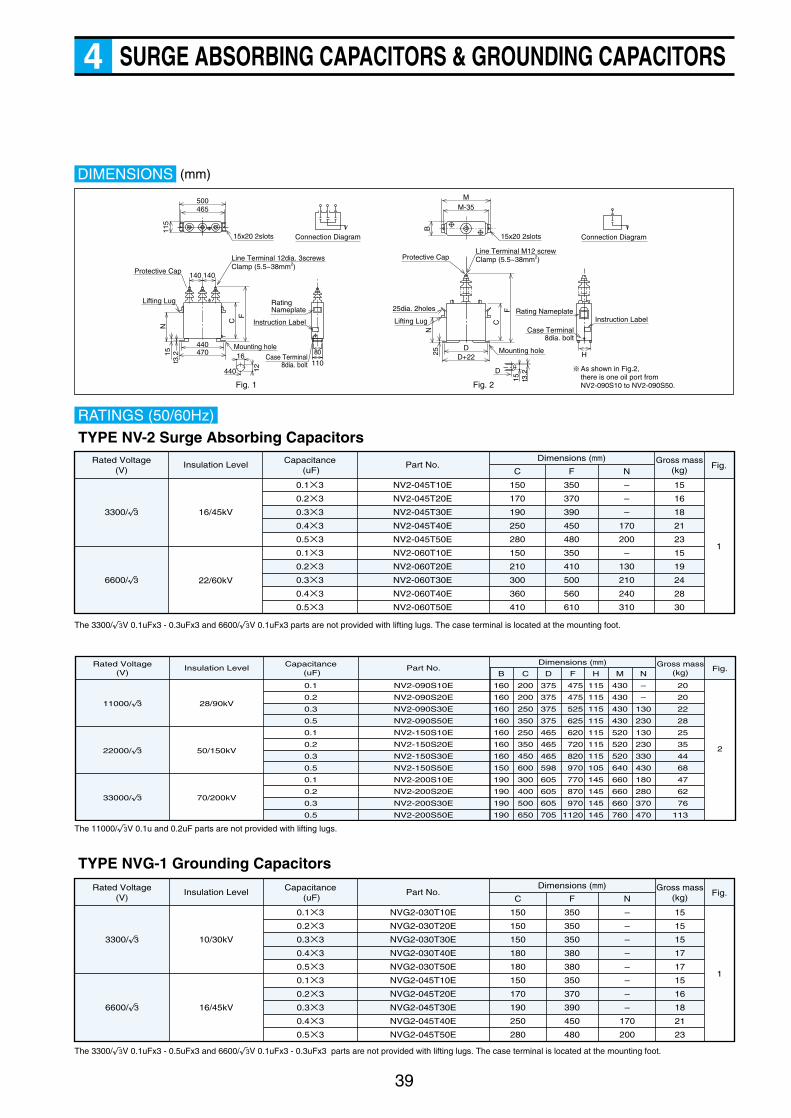
SURGE ABSORBING CAPACITORS & GROUNDING CAPACITORS4
39
DIMENSIONS
Case Terminal8dia. bolt
15 t3.2
15x20 2slots Connection Diagram
500465
115
Protective Cap
Line Terminal 12dia. 3screwsClamp (5.5~38mm2)
Lifting Lug
N
t3.2
CF
440
140 140
470Mounting hole16
440 12
Fig. 1 Fig. 2
Rating Nameplate
80
110
Mounting hole
D
N
C
F
D+22D
25
Rating Nameplate
Case Terminal8dia. bolt
Instruction Label
15x20 2slots
M-35M
H
B
Protective CapLine Terminal M12 screwClamp (5.5~38mm2)
Lifting Lug
25dia. 2holes
Connection Diagram
15
Instruction Label
As shown in Fig.2, there is one oil port from NV2-090S10 to NV2-090S50.
RATINGS (50/60Hz)
Rated Voltage(V)
16/45kV
22/60kV
3300/√3
6600/√3
Capacitance (uF)
Insulation Level Part No.
0.1×3
0.2×3
0.3×3
0.4×3
0.5×3
0.1×3
0.2×3
0.3×3
0.4×3
0.5×3
NV2-045T10E
NV2-045T20E
NV2-045T30E
NV2-045T40E
NV2-045T50E
NV2-060T10E
NV2-060T20E
NV2-060T30E
NV2-060T40E
NV2-060T50E
Dimensions (mm)
1
Fig.Gross mass
(kg)C
150
170
190
250
280
150
210
300
360
410
F
350
370
390
450
480
350
410
500
560
610
N
–
–
–
170
200
–
130
210
240
310
15
16
18
21
23
15
19
24
28
30
TYPE NV-2 Surge Absorbing Capacitors
The 3300/√3V 0.1uFx3 - 0.3uFx3 and 6600/√3V 0.1uFx3 parts are not provided with lifting lugs. The case terminal is located at the mounting foot.
Rated Voltage(V)
28/90kV
50/150kV
70/200kV
11000/√3
22000/√3
33000/√3
Capacitance (uF)
Insulation Level Part No.
0.1
0.2
0.3
0.5
0.1
0.2
0.3
0.5
0.1
0.2
0.3
0.5
NV2-090S10E
NV2-090S20E
NV2-090S30E
NV2-090S50E
NV2-150S10E
NV2-150S20E
NV2-150S30E
NV2-150S50E
NV2-200S10E
NV2-200S20E
NV2-200S30E
NV2-200S50E
Dimensions (mm)
2
Fig.Gross mass
(kg)
20
20
22
28
25
35
44
68
47
62
76
113
D
375
375
375
375
465
465
465
598
605
605
605
705
N
–
–
130
230
130
230
330
430
180
280
370
470
C
200
200
250
350
250
350
450
600
300
400
500
650
F
475
475
525
625
620
720
820
970
770
870
970
1120
B
160
160
160
160
160
160
160
150
190
190
190
190
M
430
430
430
430
520
520
520
640
660
660
660
760
H
115
115
115
115
115
115
115
105
145
145
145
145
The 11000/√3V 0.1u and 0.2uF parts are not provided with lifting lugs.
Rated Voltage(V)
10/30kV
16/45kV
3300/√3
6600/√3
Capacitance (uF)
Insulation Level Part No.
0.1×3
0.2×3
0.3×3
0.4×3
0.5×3
0.1×3
0.2×3
0.3×3
0.4×3
0.5×3
NVG2-030T10E
NVG2-030T20E
NVG2-030T30E
NVG2-030T40E
NVG2-030T50E
NVG2-045T10E
NVG2-045T20E
NVG2-045T30E
NVG2-045T40E
NVG2-045T50E
Dimensions (mm)
1
Fig.Gross mass
(kg)C
150
150
150
180
180
150
170
190
250
280
F
350
350
350
380
380
350
370
390
450
480
N
–
–
–
–
–
–
–
–
170
200
15
15
15
17
17
15
16
18
21
23
TYPE NVG-1 Grounding Capacitors
The 3300/√3V 0.1uFx3 - 0.5uFx3 and 6600/√3V 0.1uFx3 - 0.3uFx3 parts are not provided with lifting lugs. The case terminal is located at the mounting foot.
(mm)
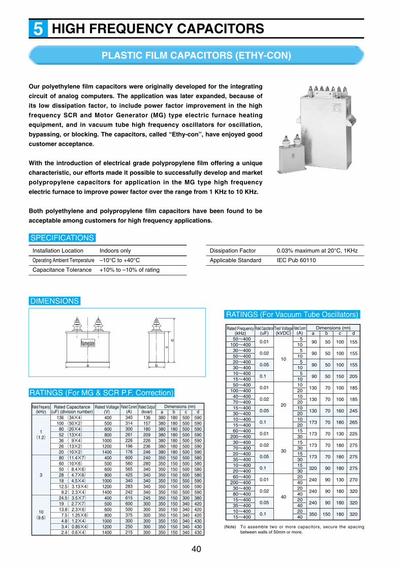
Our polyethylene film capacitors were originally developed for the integrating
circuit of analog computers. The application was later expanded, because of
its low dissipation factor, to include power factor improvement in the high
frequency SCR and Motor Generator (MG) type electric furnace heating
equipment, and in vacuum tube high frequency oscillators for oscillation,
bypassing, or blocking. The capacitors, called “Ethy-con”, have enjoyed good
customer acceptance.
With the introduction of electrical grade polypropylene film offering a unique
characteristic, our efforts made it possible to successfully develop and market
polypropylene capacitors for application in the MG type high frequency
electric furnace to improve power factor over the range from 1 KHz to 10 KHz.
Both polyethylene and polypropylene film capacitors have been found to be
acceptable among customers for high frequency applications.
PLASTIC FILM CAPACITORS (ETHY-CON)
40
HIGH FREQUENCY CAPACITORS5
Installation Location Indoors only
Operating Ambient Temperature –10°C to +40°C
Capacitance Tolerance +10% to –10% of rating
SPECIFICATIONS
Dissipation Factor 0.03% maximum at 20°C, 1KHz
Applicable Standard IEC Pub 60110
DIMENSIONS
Nameplate
a b
cd
RATINGS (For MG & SCR P.F. Correction)
136 (34×4)100 (50×2) 80 (20×4) 52 (13×4) 36 ( 9×4) 26 (13×2) 20 (10×2) 80 (11.4×7) 60 (10×6) 50 ( 8.4×6) 28 ( 4.7×6) 18 ( 4.5×4) 12.5( 3.13×4) 9.2( 2.3×4) 24.5( 3.5×7) 19 ( 2.7×7) 13.8( 2.3×6) 7.5( 1.25×6) 4.8( 1.2×4) 3.4( 0.85×4) 2.4( 0.6×4)
Rated Capacitance(uF) (division number)
Dimensions (mm)a
380380380380380380380350350350350350350350350350350350350350350
400500600800
100012001400400500600800
100012001400400500600800
100012001400
Rated Voltage(V)
340314300261226196176600560565425340283242615600500375300250215
Rated Current(A)
Rated Output(kvar)
1(1.2)
10(9.6)
3
Rated Frequency(kHz) b
180180180180180180180150150150150150150150150150150150150150150
c500500500500500500500500500500500500500500300340340340340340340
d590590590590590590590580580580580590590590380420420420430430430
136157180209226236246240280340340340340340245300300300300300300
RATINGS (For Vacuum Tube Oscillators)
0.01
0.02
0.05
0.1
0.01
0.02
0.05
0.1
0.01
0.02
0.05
0.1
0.01
0.02
0.05
0.1
50~400100~40030~40050~40020~40030~40010~40015~40050~400
100~40040~40070~40015~40030~40010~40015~40060~400
200~40030~40070~40020~40035~40010~40020~40060~400
200~40030~40080~40015~40035~40010~40015~400
5105
105
105
10102010201020102015301530153015302040204020402040
Rated Capacitance(uF)
Dimensions (mm)a
10
20
30
40
Test Voltage(kVDC)
Rated Current(A) b c d
100
100
100
150
100
100
160
180
130
180
180
180
130
180
180
180
155
155
155
205
185
185
245
265
225
275
275
275
270
320
320
320
90
90
90
90
130
130
130
173
173
173
173
320
240
240
240
350
50
50
50
50
70
70
70
70
70
70
70
90
90
90
90
150
Rated Frequency(kHz)
(Note) To assemble two or more capacitors, secure the spacingbetween walls of 50mm or more.
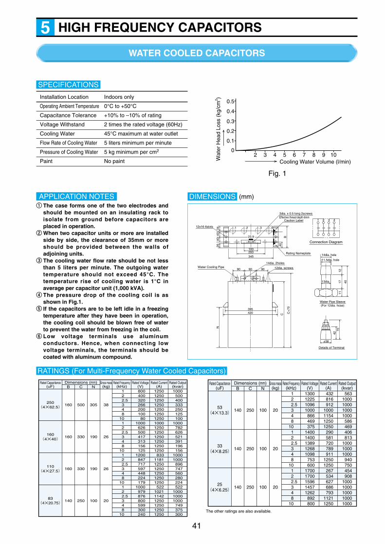
HIGH FREQUENCY CAPACITORS5
41
WATER COOLED CAPACITORS
Installation Location Indoors only
Operating Ambient Temperature 0°C to +50°C
Capacitance Tolerance +10% to –10% of rating
Voltage Withstand 2 times the rated voltage (60Hz)
Cooling Water 45°C maximum at water outlet
Flow Rate of Cooling Water 5 liters minimum per minute
Pressure of Cooling Water 5 kg minimum per cm2
Paint No paint
SPECIFICATIONS
RATINGS (For Multi-Frequency Water Cooled Capacitors)
1 2
2.5 3 4 810 1 2
2.5 3 4 810 1 2
2.5 3 4 810 1 2
2.5 3 4 810
250(4×62.5)
160(4×40)
110(4×27.5)
83(4×20.75)
Rated Frequency(kHz)
Rated Capacitance(uF)
Dimensions (mm)B
160
160
160
140
500
330
330
250
305
190
190
100
C N
38
26
26
20
Gross mass(kg)
800400320266200100
801000
626500417313156125
1200847717597448224179
1000979876800599300240
Rated Voltage(V)
12501250125012501250125012501000125012501250125012501250
833118112501250125012501250
522102111421250125012501250
Rated Current(A)
Rated Output(kvar)1000
500400333250125100
1000782626521391196156
10001000
896747560280224522
100010001000
749375300
Cooling Water Volume (l/min)Wat
er H
ead
Loss
(kg
/cm
2 )
Fig. 1
02 3 4 5 6 7 8 9 10
0.1
0.2
0.3
0.4
0.5
qq The case forms one of the two electrodes andshould be mounted on an insulating rack toisolate from ground before capacitors areplaced in operation.
ww When two capacitor units or more are installedside by side, the clearance of 35mm or moreshould be provided between the walls ofadjoining units.
ee The cooling water flow rate should be not lessthan 5 liters per minute. The outgoing watertemperature should not exceed 45°C. Thetemperature rise of cooling water is 1°C inaverage per capacitor unit (1,000 kVA).
rr The pressure drop of the cooling coil is asshown in Fig.1.
tt If the capacitors are to be left idle in a freezingtemperature after they have been in operation,the cooling coil should be blown free of waterto prevent the water from freezing in the coil.
yy Low voltage terminals use aluminumconductors. Hence, when connecting lowvoltage terminals, the terminals should becoated with aluminum compound.
APPLICATION NOTES DIMENSIONS
3dia. x 0.5 long 2screws
Connection Diagram
1 2 3 4
14dia. 2holes
Effective thread depth 6mm
12x16 6slots
Water Cooling Pipe
3440
40
3020
BC
+70
C
1217 40
7042
Water Pipe Sleeve(For 12dia. hose)
Details of Terminal
11
N40
26
23.9
100200345
90 90
11.5dia. hole
14dia. hole
13dia.
f38
90
395420
Rating Nameplate
Caution Label
12dia. screws
1 2 3 4
1 2
2.5 3 4 810 1 2
2.5 3 4 810 1 2
2.5 3 4 810
53(4×13.3)
33(4×8.25)
25(4×6.25)
Rated Frequency(kHz)
Rated Capacitance(uF) B
140
140
140
250
250
250
100
100
100
C N
20
20
20
Gross mass(kg)
1300122510961000
866469375
14001400138912681098
753600
17001700159614571262
892800
Rated Voltage(V)
432816912
1000115412501250
290581720789911
12501250
267534627686793
11211250
Rated Current(A)
Rated Output(kvar)
5631000100010001000
586469406813
100010001000
940750454908
10001000100010001000
Dimensions (mm)
The other ratings are also available.
(mm)
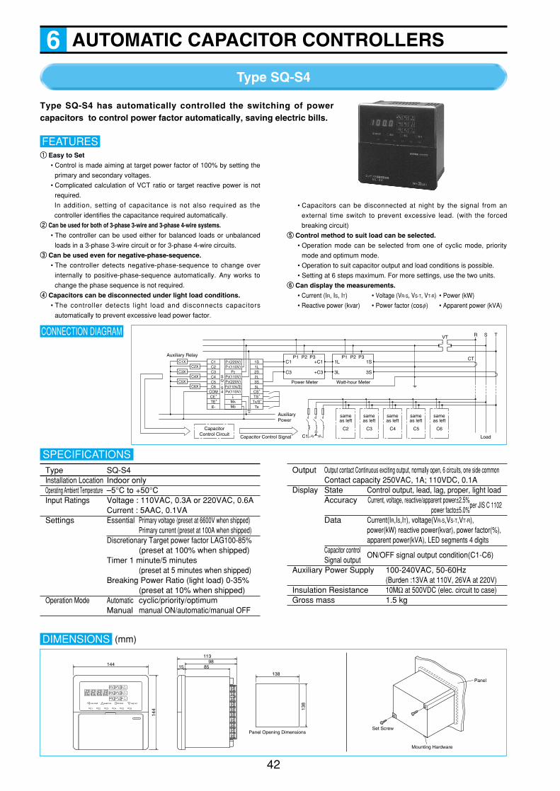
Type SQ-S4
42
AUTOMATIC CAPACITOR CONTROLLERS6
Type SQ-S4 has automatically controlled the switching of powercapacitors to control power factor automatically, saving electric bills.
CONNECTION DIAGRAM
Auxiliary Relay
AuxiliaryPower
C1X
C3X
C5X
C2X
C4X
C6X
C1C2C3C4C5C6
COMCE+
TE+
E-
1S1L2S2L3S3L
CS+
TS+
TA/S+
TB
P1(220V)P1(110V)
P2
P3(110V)P3(220V)
P0(110V)
↓MA
MB
SQ S4
CapacitorControl Circuit Capacitor Control Signal C1
P1C1
C3
+C1
+C3
P2 P3
Power Meter
P11L
3L
1S
3S
P2 P3
Watt-hour Meter
VT R S T
CT
Load
sameas left
sameas left
sameas left
sameas left
sameas left
C2 C3 C4 C5 C6
P0(110V 3)
Type SQ-S4Installation Location Indoor onlyOperating Ambient Temperature –5°C to +50°CInput Ratings Voltage : 110VAC, 0.3A or 220VAC, 0.6A
Current : 5AAC, 0.1VASettings Essential Primary voltage (preset at 6600V when shipped)
Primary current (preset at 100A when shipped)Discretionary Target power factor LAG100-85%
(preset at 100% when shipped)Timer 1 minute/5 minutes
(preset at 5 minutes when shipped)Breaking Power Ratio (light load) 0-35%
(preset at 10% when shipped)Operation Mode Automatic cyclic/priority/optimum
Manual manual ON/automatic/manual OFF
SPECIFICATIONSOutput Output contact Continuous exciting output, normally open, 6 circuits, one side common
Contact capacity 250VAC, 1A; 110VDC, 0.1ADisplay State Control output, lead, lag, proper, light load
Accuracy Current, voltage, reactive/apparent power±2.5%power facto±5.0%
Data Current(IR,IS,IT), voltage(VR-S,VS-T,VT-R),power(kW) reactive power(kvar), power factor(%),apparent power(kVA), LED segments 4 digits
Capacitor controlSignal output
ON/OFF signal output condition(C1-C6)
Auxiliary Power Supply 100-240VAC, 50-60Hz(Burden :13VA at 110V, 26VA at 220V)
Insulation Resistance 10MΩ at 500VDC (elec. circuit to case)Gross mass 1.5 kg
DIMENSIONS
Low load
C1 C2 C3 C4 C5 C6
NormalLead out Lag out
%C1
kvarC2
kwC3
kVAC4
kvC5
AC6
RR-S
SS-T
TT-R
144
144
11398
8515
138
138
Panel Opening DimensionsSet Screw
Mounting Hardware
Panel
qq Easy to Set
• Control is made aiming at target power factor of 100% by setting the
primary and secondary voltages.
• Complicated calculation of VCT ratio or target reactive power is not
required.
In addition, setting of capacitance is not also required as the
controller identifies the capacitance required automatically.
ww Can be used for both of 3-phase 3-wire and 3-phase 4-wire systems.
• The controller can be used either for balanced loads or unbalanced
loads in a 3-phase 3-wire circuit or for 3-phase 4-wire circuits.
ee Can be used even for negative-phase-sequence.
• The controller detects negative-phase-sequence to change over
internally to positive-phase-sequence automatically. Any works to
change the phase sequence is not required.
rr Capacitors can be disconnected under light load conditions.
• The controller detects light load and disconnects capacitors
automatically to prevent excessive lead power factor.
FEATURES
• Capacitors can be disconnected at night by the signal from an
external time switch to prevent excessive lead. (with the forced
breaking circuit)
tt Control method to suit load can be selected.
• Operation mode can be selected from one of cyclic mode, priority
mode and optimum mode.
• Operation to suit capacitor output and load conditions is possible.
• Setting at 6 steps maximum. For more settings, use the two units.
yy Can display the measurements.
• Current (IR, IS, IT) • Voltage (VR-S, VS-T, VT-R) • Power (kW)
• Reactive power (kvar) • Power factor (cosf) • Apparent power (kVA)
per JIS C 1102
(mm)
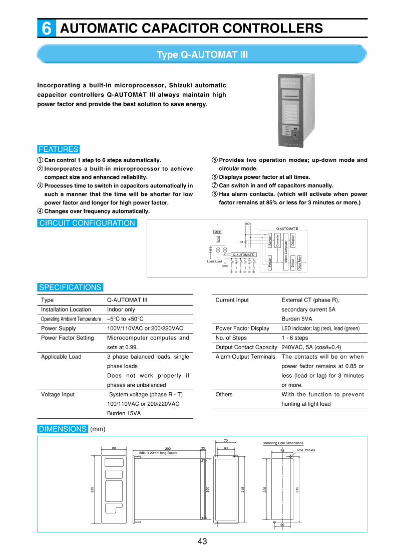
AUTOMATIC CAPACITOR CONTROLLERS6
43
Type Q-AUTOMAT III
Incorporating a built-in microprocessor, Shizuki automatic
capacitor controllers Q-AUTOMAT III always maintain high
power factor and provide the best solution to save energy.
qq Can control 1 step to 6 steps automatically.ww Incorporates a built-in microprocessor to achieve
compact size and enhanced reliability. ee Processes time to switch in capacitors automatically in
such a manner that the time will be shorter for low
power factor and longer for high power factor.rr Changes over frequency automatically.
FEATUREStt Provides two operation modes; up-down mode and
circular mode.yy Displays power factor at all times. uu Can switch in and off capacitors manually. ii Has alarm contacts. (which will activate when power
factor remains at 85% or less for 3 minutes or more.)
CIRCUIT CONFIGURATIONMOF
Q-AUTOMAT
Q-AUTOMAT
200V
CT
Load LoadLoad
Sen
sor
Pow
er
Con
verte
r
Dis
play
Driv
er
Out
put R
elay
Mic
ro C
ompu
ter
Type Q-AUTOMAT III
Installation Location Indoor only
Operating Ambient Temperature –5°C to +50°C
Power Supply 100V/110VAC or 200/220VAC
Power Factor Setting Microcomputer computes and
sets at 0.99.
Applicable Load 3 phase balanced loads, single
phase loads
Does not work properly if
phases are unbalanced
Voltage Input System voltage (phase R - T)
100/110VAC or 200/220VAC
Burden 15VA
SPECIFICATIONS
Current Input External CT (phase R),
secondary current 5A
Burden 5VA
Power Factor Display LED indicator; lag (red), lead (green)
No. of Steps 1 - 6 steps
Output Contact Capacity 240VAC, 5A (cosq=0.4)
Alarm Output Terminals The contacts will be on when
power factor remains at 0.85 or
less (lead or lag) for 3 minutes
or more.
Others With the function to prevent
hunting at light load
DIMENSIONS
80 2005dia. x 20mm long 2studs
200
215
215
205
22
70
75
60
6dia. 2holes60
225
Mounting Hole Dimensions
(mm)

URL : http://www.shizuki.co.jp
Headquarters : 10-45 Taisha-cho, Nishinomiya, Hyogo 662-0867 Japan
TEL : +81-798-74-5821 FAX : +81-798-73-0807
Tokyo Branch Office : 1-16-8 Hamamatsu-cho, Minato, Tokyo 105-0013 Japan
TEL : +81-3-5473-3911 FAX : +81-3-5473-3922
Korea Representative Office : Rm4-207 Circulation Center, Imsu-Dong Kumi-Shi
Kyung-Buk,Korea
TEL : +82-54-475-0097 FAX : +82-54-475-0098
Malaysia Representative Office : Level 28,Central Plaza 34 Jalan Sultan Ismail
50250 Kuala Lumpur, Malaysia
TEL : +60-3-2147-4507 FAX : +60-3-2147-4505
Offshore Subsidiary
American Shizuki Corp : 301 West O Street Ogallala, NE 69153 USA
TEL : +1-308-284-3611 FAX : +1-308-284-2708
Note) The contents of this brochure issued in Sep 2005 are subject to change without notice. Jul 2008 MD 1000