5- Ch06- Capacitors and Inductors-Sadiku
38
215 Capacitors and Inductors But in science the credit goes to the man who convinces the world, not to the man whom the idea first occurs. —Francis Darwin chapter 6 Enhancing Your Skills and Your Career ABET EC 2000 criteria (3.c), “an ability to design a system, component, or process to meet desired needs.” The “ability to design a system, component, or process to meet desired needs” is why engineers are hired. That is why this is the most important technical skill that an engineer has. Interestingly, your success as an engineer is directly proportional to your ability to com- municate but your being able to design is why you will be hired in the first place. Design takes place when you have what is termed an open-ended problem that eventually is defined by the solution. Within the context of this course or textbook, we can only explore some of the elements of design. Pursuing all of the steps of our problem-solving technique teaches you several of the most important elements of the design process. Probably the most important part of design is clearly defining what the system, component, process, or, in our case, problem is. Rarely is an engineer given a perfectly clear assignment. Therefore, as a student, you can develop and enhance this skill by asking yourself, your col- leagues, or your professors questions designed to clarify the problem statement. Exploring alternative solutions is another important part of the design process. Again, as a student, you can practice this part of the design process on almost every problem you work. Evaluating your solutions is critical to any engineering assignment. Again, this is a skill that you as a student can practice on every prob- lem you work. Photo by Charles Alexander
-
Upload
iutoic-dhaka -
Category
Documents
-
view
1 -
download
0
Transcript of 5- Ch06- Capacitors and Inductors-Sadiku

215
Capacitors andInductorsBut in science the credit goes to the man who convinces the world, notto the man whom the idea first occurs.
—Francis Darwin
c h a p t e r
6
Enhancing Your Skills and Your Career
ABET EC 2000 criteria (3.c), “an ability to design a system,component, or process to meet desired needs.”The “ability to design a system, component, or process to meetdesired needs” is why engineers are hired. That is why this is themost important technical skill that an engineer has. Interestingly, yoursuccess as an engineer is directly proportional to your ability to com-municate but your being able to design is why you will be hired inthe first place.
Design takes place when you have what is termed an open-endedproblem that eventually is defined by the solution. Within the contextof this course or textbook, we can only explore some of the elementsof design. Pursuing all of the steps of our problem-solving techniqueteaches you several of the most important elements of the designprocess.
Probably the most important part of design is clearly defining whatthe system, component, process, or, in our case, problem is. Rarely isan engineer given a perfectly clear assignment. Therefore, as a student,you can develop and enhance this skill by asking yourself, your col-leagues, or your professors questions designed to clarify the problemstatement.
Exploring alternative solutions is another important part of thedesign process. Again, as a student, you can practice this part of thedesign process on almost every problem you work.
Evaluating your solutions is critical to any engineering assignment.Again, this is a skill that you as a student can practice on every prob-lem you work.
Photo by Charles Alexander
ale29559_ch06.qxd 07/08/2008 10:59 AM Page 215

IntroductionSo far we have limited our study to resistive circuits. In this chapter,we shall introduce two new and important passive linear circuit ele-ments: the capacitor and the inductor. Unlike resistors, which dissipateenergy, capacitors and inductors do not dissipate but store energy,which can be retrieved at a later time. For this reason, capacitors andinductors are called storage elements.
The application of resistive circuits is quite limited. With the intro-duction of capacitors and inductors in this chapter, we will be able toanalyze more important and practical circuits. Be assured that the cir-cuit analysis techniques covered in Chapters 3 and 4 are equally appli-cable to circuits with capacitors and inductors.
We begin by introducing capacitors and describing how to com-bine them in series or in parallel. Later, we do the same for inductors.As typical applications, we explore how capacitors are combined withop amps to form integrators, differentiators, and analog computers.
CapacitorsA capacitor is a passive element designed to store energy in its elec-tric field. Besides resistors, capacitors are the most common electricalcomponents. Capacitors are used extensively in electronics, communi-cations, computers, and power systems. For example, they are used inthe tuning circuits of radio receivers and as dynamic memory elementsin computer systems.
A capacitor is typically constructed as depicted in Fig. 6.1.
6.2
6.1
216 Chapter 6 Capacitors and Inductors
In contrast to a resistor, which spendsor dissipates energy irreversibly, aninductor or capacitor stores or releasesenergy (i.e., has a memory).
Metal plates,each with area A
d
Dielectric with permittivity
Figure 6.1A typical capacitor.
−
−
−
−q+q
+
+
+
+
+
+
−+v
Figure 6.2A capacitor with applied voltage v.
Alternatively, capacitance is the amountof charge stored per plate for a unitvoltage difference in a capacitor.
A capacitor consists of two conducting plates separated by an insu-lator (or dielectric).
In many practical applications, the plates may be aluminum foil whilethe dielectric may be air, ceramic, paper, or mica.
When a voltage source is connected to the capacitor, as inFig. 6.2, the source deposits a positive charge q on one plate and a neg-ative charge on the other. The capacitor is said to store the electriccharge. The amount of charge stored, represented by q, is directly pro-portional to the applied voltage so that
(6.1)
where C, the constant of proportionality, is known as the capacitanceof the capacitor. The unit of capacitance is the farad (F), in honor ofthe English physicist Michael Faraday (1791–1867). From Eq. (6.1),we may derive the following definition.
q Cv
v
q
v
Capacitance is the ratio of the charge on one plate of a capacitor tothe voltage difference between the two plates, measured in farads (F).
Note from Eq. (6.1) that 1 farad 1 coulomb/volt.
ale29559_ch06.qxd 07/08/2008 10:59 AM Page 216
Although the capacitance C of a capacitor is the ratio of the chargeq per plate to the applied voltage it does not depend on q or Itdepends on the physical dimensions of the capacitor. For example, forthe parallel-plate capacitor shown in Fig. 6.1, the capacitance is given by
(6.2)
where A is the surface area of each plate, d is the distance betweenthe plates, and is the permittivity of the dielectric material betweenthe plates. Although Eq. (6.2) applies to only parallel-plate capacitors,we may infer from it that, in general, three factors determine the valueof the capacitance:
1. The surface area of the plates—the larger the area, the greater thecapacitance.
2. The spacing between the plates—the smaller the spacing, the greaterthe capacitance.
3. The permittivity of the material—the higher the permittivity, thegreater the capacitance.
Capacitors are commercially available in different values and types.Typically, capacitors have values in the picofarad (pF) to microfarad range. They are described by the dielectric material they are made of andby whether they are of fixed or variable type. Figure 6.3 shows the cir-cuit symbols for fixed and variable capacitors. Note that according to thepassive sign convention, if and or if and thecapacitor is being charged, and if the capacitor is discharging.
Figure 6.4 shows common types of fixed-value capacitors. Poly-ester capacitors are light in weight, stable, and their change with tem-perature is predictable. Instead of polyester, other dielectric materialssuch as mica and polystyrene may be used. Film capacitors are rolledand housed in metal or plastic films. Electrolytic capacitors producevery high capacitance. Figure 6.5 shows the most common types ofvariable capacitors. The capacitance of a trimmer (or padder) capacitor
v i 6 0,i 6 0,v 6 0i 7 0v 7 0
(mF)
C A
d
v.v,
6.2 Capacitors 217
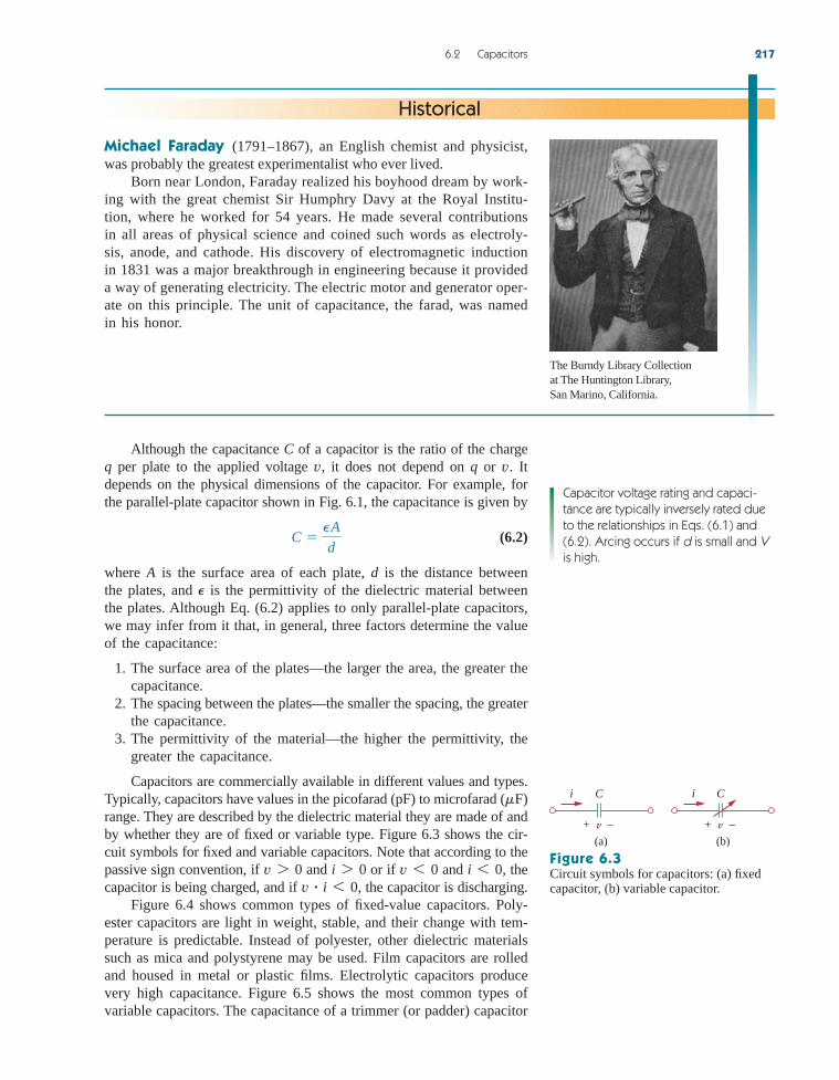
Michael Faraday (1791–1867), an English chemist and physicist,was probably the greatest experimentalist who ever lived.
Born near London, Faraday realized his boyhood dream by work-ing with the great chemist Sir Humphry Davy at the Royal Institu-tion, where he worked for 54 years. He made several contributionsin all areas of physical science and coined such words as electroly-sis, anode, and cathode. His discovery of electromagnetic inductionin 1831 was a major breakthrough in engineering because it provideda way of generating electricity. The electric motor and generator oper-ate on this principle. The unit of capacitance, the farad, was namedin his honor.
Historical
Capacitor voltage rating and capaci-tance are typically inversely rated dueto the relationships in Eqs. (6.1) and(6.2). Arcing occurs if d is small and Vis high.
Figure 6.3Circuit symbols for capacitors: (a) fixedcapacitor, (b) variable capacitor.
i iC
v+ −
C
v+ −(a) (b)
The Burndy Library Collectionat The Huntington Library, San Marino, California.
ale29559_ch06.qxd 07/16/2008 12:41 PM Page 217

is often placed in parallel with another capacitor so that the equivalentcapacitance can be varied slightly. The capacitance of the variable aircapacitor (meshed plates) is varied by turning the shaft. Variable capac-itors are used in radio receivers allowing one to tune to various sta-tions. In addition, capacitors are used to block dc, pass ac, shift phase,store energy, start motors, and suppress noise.
To obtain the current-voltage relationship of the capacitor, we takethe derivative of both sides of Eq. (6.1). Since
(6.3)
differentiating both sides of Eq. (6.1) gives
(6.4)
This is the current-voltage relationship for a capacitor, assuming thepassive sign convention. The relationship is illustrated in Fig. 6.6 fora capacitor whose capacitance is independent of voltage. Capacitorsthat satisfy Eq. (6.4) are said to be linear. For a nonlinear capacitor,the plot of the current-voltage relationship is not a straight line.Although some capacitors are nonlinear, most are linear. We willassume linear capacitors in this book.
The voltage-current relation of the capacitor can be obtained byintegrating both sides of Eq. (6.4). We get
(6.5)
or
(6.6)
where is the voltage across the capacitor at time Equation (6.6) shows that capacitor voltage depends on the past history
t0.v(t0) q(t0)C
v 1
C
t
t0
i dt v(t0)
v 1
C
t
i dt
i C
dvdt
i dq
dt
218 Chapter 6 Capacitors and Inductors
(a) (b) (c)
Figure 6.4Fixed capacitors: (a) polyester capacitor, (b) ceramic capacitor, (c) electrolytic capacitor.Courtesy of Tech America.
Figure 6.5Variable capacitors: (a) trimmer capacitor,(b) filmtrim capacitor.Courtesy of Johanson.
According to Eq. (6.4), for a capacitorto carry current, its voltage must varywith time. Hence, for constant voltage,i 0.
Slope = C
dv ⁄dt0
i
Figure 6.6Current-voltage relationship of a capacitor.
(a)
(b)
ale29559_ch06.qxd 07/08/2008 10:59 AM Page 218

of the capacitor current. Hence, the capacitor has memory—a propertythat is often exploited.
The instantaneous power delivered to the capacitor is
(6.7)
The energy stored in the capacitor is therefore
(6.8)
We note that because the capacitor was uncharged atThus,
(6.9)
Using Eq. (6.1), we may rewrite Eq. (6.9) as
(6.10)
Equation (6.9) or (6.10) represents the energy stored in the electric fieldthat exists between the plates of the capacitor. This energy can beretrieved, since an ideal capacitor cannot dissipate energy. In fact, theword capacitor is derived from this element’s capacity to store energyin an electric field.
We should note the following important properties of a capacitor:
1. Note from Eq. (6.4) that when the voltage across a capacitor is notchanging with time (i.e., dc voltage), the current through the capac-itor is zero. Thus,
w q2
2C
w 1
2 Cv2
t .v() 0,
w t
p dt C
t
v
dvdt
dt C v(t)
v() v dv
1
2 Cv2 ` v(t)
v()
p vi C v
dvdt
6.2 Capacitors 219
A capacitor is an open circuit to dc.
However, if a battery (dc voltage) is connected across a capacitor,the capacitor charges.
2. The voltage on the capacitor must be continuous.
The voltage on a capacitor cannot change abruptly.
The capacitor resists an abrupt change in the voltage across it.According to Eq. (6.4), a discontinuous change in voltage requiresan infinite current, which is physically impossible. For example,the voltage across a capacitor may take the form shown inFig. 6.7(a), whereas it is not physically possible for the capacitorvoltage to take the form shown in Fig. 6.7(b) because of the abruptchanges. Conversely, the current through a capacitor can changeinstantaneously.
3. The ideal capacitor does not dissipate energy. It takes power fromthe circuit when storing energy in its field and returns previouslystored energy when delivering power to the circuit.
4. A real, nonideal capacitor has a parallel-model leakage resistance,as shown in Fig. 6.8. The leakage resistance may be as high as
v
t
(a)
v
t
(b)
Figure 6.7Voltage across a capacitor: (a) allowed,(b) not allowable; an abrupt change is notpossible.
An alternative way of looking at this isusing Eq. (6.9), which indicates thatenergy is proportional to voltagesquared. Since injecting or extractingenergy can only be done over somefinite time, voltage cannot changeinstantaneously across a capacitor.
Leakage resistance
Capacitance
Figure 6.8Circuit model of a nonideal capacitor.
ale29559_ch06.qxd 07/08/2008 10:59 AM Page 219

and can be neglected for most practical applications. Forthis reason, we will assume ideal capacitors in this book.100 M
220 Chapter 6 Capacitors and Inductors
Example 6.1 (a) Calculate the charge stored on a 3-pF capacitor with 20 V across it.(b) Find the energy stored in the capacitor.
Solution:
(a) Since
(b) The energy stored is
w 1
2 Cv2
1
2 3 1012 400 600 pJ
q 3 1012 20 60 pC
q Cv,
What is the voltage across a capacitor if the charge on one plateis 0.12 mC? How much energy is stored?
Answer: 40 V, 2.4 mJ.
3-mFPractice Problem 6.1
The voltage across a capacitor is
Calculate the current through it.
Solution:By definition, the current is
5 106 6000 10 sin 6000t 0.3 sin 6000t A
i(t) C dvdt
5 106 d
dt (10 cos 6000t)
v(t) 10 cos 6000t V
5-mFExample 6.2
If a capacitor is connected to a voltage source with
determine the current through the capacitor.
Answer: cos 2000t A.
v(t) 50 sin 2000t V
10-mFPractice Problem 6.2
Determine the voltage across a capacitor if the current through it is
Assume that the initial capacitor voltage is zero.
i(t) 6e3000t mA
2-mFExample 6.3
ale29559_ch06.qxd 07/08/2008 10:59 AM Page 220

Solution:
Since and ,
3 103
3000 e3000t `
0
t
(1 e3000t) V
v 1
2 106 t
0
6e3000t dt 103
v(0) 0v 1
C
t
0
i dt v(0)
6.2 Capacitors 221
Practice Problem 6.3
Determine the current through a capacitor whose voltage isshown in Fig. 6.9.
Solution:The voltage waveform can be described mathematically as
Since and , we take the derivative of to obtain
Thus the current waveform is as shown in Fig. 6.10.
d 10 mA 0 6 t 6 1
10 mA 1 6 t 6 3
10 mA 3 6 t 6 4
0 otherwise
i(t) 200 106 d 50 0 6 t 6 1
50 1 6 t 6 3
50 3 6 t 6 4
0 otherwise
vC 200 mFi C dvdt
v(t) d 50t V 0 6 t 6 1
100 50t V 1 6 t 6 3
200 50t V 3 6 t 6 4
0 otherwise
200-mF Example 6.4v (t)
04321
50
−50
t
Figure 6.9For Example 6.4.
i (mA)
04321
10
−10
t
Figure 6.10For Example 6.4.
An initially uncharged 1-mF capacitor has the current shown inFig. 6.11 across it. Calculate the voltage across it at and
Answer: 100 mV, 400 mV.
t 5 ms.t 2 ms
Practice Problem 6.4i (mA)
0642
100
t (ms)
Figure 6.11For Practice Prob. 6.4.
The current through a capacitor is Calculate the voltage across it at and Take
Answer: 1.736 V.93.14 mV,
v(0) 0.t 5 ms.t 1 msi(t) 50 sin 120 p t mA.100-mF
ale29559_ch06.qxd 07/08/2008 10:59 AM Page 221

Solution:Under dc conditions, we replace each capacitor with an open circuit,as shown in Fig. 6.12(b). The current through the series combinationof the and resistors is obtained by current division as
Hence, the voltages and across the capacitors are
and the energies stored in them are
w2 1
2 C2v2
2 1
2 (4 103)(8)2 128 mJ
w1 1
2 C1v1
2 1
2 (2 103)(4)2 16 mJ
v1 2000i 4 V v2 4000i 8 V
v2v1
i 3
3 2 4 (6 mA) 2 mA
4-k2-k
222 Chapter 6 Capacitors and Inductors
Example 6.5 Obtain the energy stored in each capacitor in Fig. 6.12(a) under dcconditions.
Figure 6.12For Example 6.5.
Under dc conditions, find the energy stored in the capacitors in Fig. 6.13.
Answer: , 135 mJ.810 mJ
Practice Problem 6.5
10 V +− 6 kΩ
1 kΩ
30 F
20 F
3 kΩ
Figure 6.13For Practice Prob. 6.5.
Series and Parallel CapacitorsWe know from resistive circuits that the series-parallel combination is apowerful tool for reducing circuits. This technique can be extended toseries-parallel connections of capacitors, which are sometimes encoun-tered. We desire to replace these capacitors by a single equivalentcapacitor
In order to obtain the equivalent capacitor of N capacitors inparallel, consider the circuit in Fig. 6.14(a). The equivalent circuit is
Ceq
Ceq.
6.3
v1+ −
v2
+
−6 mA 3 kΩ
5 kΩ4 kΩ
2 kΩ
2 mF
4 mF
(a)
6 mA 3 kΩ
5 kΩ
4 kΩ
2 kΩ
(b)
i
ale29559_ch06.qxd 07/08/2008 10:59 AM Page 222

in Fig. 6.14(b). Note that the capacitors have the same voltage acrossthem. Applying KCL to Fig. 6.14(a),
(6.11)
But Hence,
(6.12)
where
(6.13)Ceq C1 C2 C3 p CN
aaN
k1Ckb dv
dt Ceq
dvdt
i C1
dvdt
C2
dvdt
C3
dvdt
p CN
dvdt
ik Ck dvdt.
i i1 i2 i3 p iN
v
6.3 Series and Parallel Capacitors 223
i C1
(a)
i1
C2 C3 CN
iN
v+
−
i
(b)
Ceq v+
−
i2 i3
Figure 6.14(a) Parallel-connected N capacitors, (b) equivalent circuit for the parallelcapacitors.
The equivalent capacitance of N parallel-connected capacitors is thesum of the individual capacitances.
We observe that capacitors in parallel combine in the same manner asresistors in series.
We now obtain of N capacitors connected in series by com-paring the circuit in Fig. 6.15(a) with the equivalent circuit inFig. 6.15(b). Note that the same current i flows (and consequentlythe same charge) through the capacitors. Applying KVL to the loopin Fig. 6.15(a),
(6.14)
But Therefore,
(6.15)
where
(6.16)1
Ceq
1
C1
1
C2
1
C3 p
1
CN
1
Ceq
t
t0
i (t) dt v(t0)
p vN
(t0)
a 1
C1
1
C2 p
1
CNb
t
t0
i (t) dt v1(t0) v2
(t0)
p 1
CN
t
t0
i (t) dt vN (t0)
v 1
C1
t
t0
i (t) dt v1(t0) 1
C2
t
t0
i (t) dt v2 (t0)
vk 1
Ck
t
t0
i (t) dt vk
(t0).
v v1 v2 v3 p vN
Ceq
v
C1
(a)
C2 C3 CN
v1 v2 v3 vN+−
i
+ −+ −+ − + −
v
(b)
Ceq v+−
i
+
−
Figure 6.15(a) Series-connected N capacitors, (b) equivalent circuit for the series capacitor.
ale29559_ch06.qxd 07/08/2008 10:59 AM Page 223

The initial voltage across is required by KVL to be the sumof the capacitor voltages at Or according to Eq. (6.15),
Thus, according to Eq. (6.16),
v(t0) v1(t0) v2(t0) p vN (t0)
t0.Ceqv(t0)
224 Chapter 6 Capacitors and Inductors
The equivalent capacitance of series-connected capacitors is thereciprocal of the sum of the reciprocals of the individual capacitances.
Note that capacitors in series combine in the same manner as resistorsin parallel. For (i.e., two capacitors in series), Eq. (6.16)becomes
or
(6.17)Ceq C1C2
C1 C2
1
Ceq
1
C1
1
C2
N 2
Example 6.6 Find the equivalent capacitance seen between terminals a and b of thecircuit in Fig. 6.16.
a
b
Ceq
5 F
20 F 20 F6 F
60 F
Figure 6.16For Example 6.6.
Solution:The and capacitors are in series; their equivalent capaci-tance is
This capacitor is in parallel with the and capacitors;their combined capacitance is
This capacitor is in series with the capacitor. Hence, theequivalent capacitance for the entire circuit is
Ceq 30 60
30 60 20 mF
60-mF30-mF
4 6 20 30 mF
20-mF6-mF4-mF
20 5
20 5 4 mF
5-mF20-mF
ale29559_ch06.qxd 07/08/2008 10:59 AM Page 224

6.3 Series and Parallel Capacitors 225
Find the equivalent capacitance seen at the terminals of the circuit inFig. 6.17.
Answer: 40 mF.
Practice Problem 6.6
Ceq120 F20 F70 F
60 F
50 F
Figure 6.17For Practice Prob. 6.6.
Example 6.7
20 mF40 mF
30 mF20 mF
30 V +−
v1 v2
v3
+
−
+ − + −
Figure 6.18For Example 6.7.
Ceq30 V +−
Figure 6.19Equivalent circuit for Fig. 6.18.
Practice Problem 6.7
30 F20 F
60 F40 F
60 V +−
v1 v3
v2 v4
+ − + −+
−
+
−
Figure 6.20For Practice Prob. 6.7.
For the circuit in Fig. 6.18, find the voltage across each capacitor.
Solution:We first find the equivalent capacitance , shown in Fig. 6.19. The twoparallel capacitors in Fig. 6.18 can be combined to get This 60-mF capacitor is in series with the 20-mF and 30-mF capacitors.Thus,
The total charge is
This is the charge on the 20-mF and 30-mF capacitors, because they arein series with the 30-V source. (A crude way to see this is to imaginethat charge acts like current, since ) Therefore,
Having determined and , we now use KVL to determine by
Alternatively, since the 40-mF and 20-mF capacitors are in parallel,they have the same voltage and their combined capacitance is
This combined capacitance is in series with the 20-mF and30-mF capacitors and consequently has the same charge on it. Hence,
v3 q
60 mF
0.3
60 103 5 V
20 60 mF.40 v3
v3 30 v1 v2 5 V
v3v2v1
v1 q
C1
0.3
20 103 15 V v2 q
C2
0.3
30 103 10 V
i dqdt.
q Ceq v 10 103 30 0.3 C
Ceq 1
160 1
30 120
mF 10 mF
60 mF.40 20 Ceq
Find the voltage across each of the capacitors in Fig. 6.20.
Answer: v4 20 V.v3 10 V,v2 30 V,v1 30 V,
ale29559_ch06.qxd 07/08/2008 10:59 AM Page 225

InductorsAn inductor is a passive element designed to store energy in its mag-netic field. Inductors find numerous applications in electronic andpower systems. They are used in power supplies, transformers, radios,TVs, radars, and electric motors.
Any conductor of electric current has inductive properties and maybe regarded as an inductor. But in order to enhance the inductive effect,a practical inductor is usually formed into a cylindrical coil with manyturns of conducting wire, as shown in Fig. 6.21.
6.4
226 Chapter 6 Capacitors and Inductors
An inductor consists of a coil of conducting wire.
If current is allowed to pass through an inductor, it is found that thevoltage across the inductor is directly proportional to the time rate ofchange of the current. Using the passive sign convention,
(6.18)
where L is the constant of proportionality called the inductance of theinductor. The unit of inductance is the henry (H), named in honor ofthe American inventor Joseph Henry (1797–1878). It is clear fromEq. (6.18) that 1 henry equals 1 volt-second per ampere.
v L
di
dt
Length, Cross-sectional area, A
Core material
Number of turns, N
Figure 6.21Typical form of an inductor.
In view of Eq. (6.18), for an inductorto have voltage across its terminals, itscurrent must vary with time. Hence,v 0 for constant current throughthe inductor.
Inductance is the property whereby an inductor exhibits oppositionto the change of current flowing through it, measured in henrys (H).
The inductance of an inductor depends on its physical dimensionand construction. Formulas for calculating the inductance of inductorsof different shapes are derived from electromagnetic theory and can befound in standard electrical engineering handbooks. For example, forthe inductor, (solenoid) shown in Fig. 6.21,
(6.19)
where N is the number of turns, is the length, A is the cross-sectionalarea, and is the permeability of the core. We can see from Eq. (6.19)that inductance can be increased by increasing the number of turns ofcoil, using material with higher permeability as the core, increasing thecross-sectional area, or reducing the length of the coil.
Like capacitors, commercially available inductors come in differ-ent values and types. Typical practical inductors have inductance valuesranging from a few microhenrys ( ), as in communication systems,to tens of henrys (H) as in power systems. Inductors may be fixed orvariable. The core may be made of iron, steel, plastic, or air. The termscoil and choke are also used for inductors. Common inductors areshown in Fig. 6.22. The circuit symbols for inductors are shown inFig. 6.23, following the passive sign convention.
Equation (6.18) is the voltage-current relationship for an inductor.Figure 6.24 shows this relationship graphically for an inductor whose
mH
m
/
L N
2mA
/
(a)
(b)
(c)
Figure 6.22Various types of inductors: (a) solenoidalwound inductor, (b) toroidal inductor,(c) chip inductor.Courtesy of Tech America.
ale29559_ch06.qxd 07/08/2008 10:59 AM Page 226

inductance is independent of current. Such an inductor is known as alinear inductor. For a nonlinear inductor, the plot of Eq. (6.18) willnot be a straight line because its inductance varies with current. Wewill assume linear inductors in this textbook unless stated otherwise.
The current-voltage relationship is obtained from Eq. (6.18) as
Integrating gives
(6.20)
or
(6.21)
where is the total current for and Theidea of making is practical and reasonable, because theremust be a time in the past when there was no current in the inductor.
The inductor is designed to store energy in its magnetic field. Theenergy stored can be obtained from Eq. (6.18). The power delivered tothe inductor is
(6.22)
The energy stored is
(6.23)
L t
i di 1
2 Li2(t)
1
2 Li2()
w t
p dt t
aL
di
dtbi dt
p vi aL
di
dtbi
i() 0i() 0. 6 t 6 t0i(t0)
i 1
L
t
t0
v
(t) dt i (t0)
i 1
L
t
v
(t) dt
di 1
L v dt
6.4 Inductors 227
Joseph Henry (1797–1878), an American physicist, discovered induc-tance and constructed an electric motor.
Born in Albany, New York, Henry graduated from Albany Acad-emy and taught philosophy at Princeton University from 1832 to 1846.He was the first secretary of the Smithsonian Institution. He conductedseveral experiments on electromagnetism and developed powerful elec-tromagnets that could lift objects weighing thousands of pounds. Inter-estingly, Joseph Henry discovered electromagnetic induction beforeFaraday but failed to publish his findings. The unit of inductance, thehenry, was named after him.
Historical
Slope = L
di ⁄dt0
v
i i i
(a)
v L
+
−
(b)
v L
+
−
(c)
v L
+
−
Figure 6.23Circuit symbols for inductors: (a) air-core,(b) iron-core, (c) variable iron-core.
Figure 6.24Voltage-current relationship of an inductor.
ale29559_ch06.qxd 07/08/2008 10:59 AM Page 227

Since
(6.24)
We should note the following important properties of an inductor.
1. Note from Eq. (6.18) that the voltage across an inductor is zerowhen the current is constant. Thus,
w 1
2 Li2
i () 0,
228 Chapter 6 Capacitors and Inductors
An inductor acts like a short circuit to dc.
2. An important property of the inductor is its opposition to thechange in current flowing through it.
The current through an inductor cannot change instantaneously.
According to Eq. (6.18), a discontinuous change in the currentthrough an inductor requires an infinite voltage, which is not phys-ically possible. Thus, an inductor opposes an abrupt change in thecurrent through it. For example, the current through an inductormay take the form shown in Fig. 6.25(a), whereas the inductor cur-rent cannot take the form shown in Fig. 6.25(b) in real-life situa-tions due to the discontinuities. However, the voltage across aninductor can change abruptly.
3. Like the ideal capacitor, the ideal inductor does not dissipateenergy. The energy stored in it can be retrieved at a later time. Theinductor takes power from the circuit when storing energy anddelivers power to the circuit when returning previously storedenergy.
4. A practical, nonideal inductor has a significant resistive component,as shown in Fig. 6.26. This is due to the fact that the inductor ismade of a conducting material such as copper, which has someresistance. This resistance is called the winding resistance , andit appears in series with the inductance of the inductor. The pres-ence of makes it both an energy storage device and an energydissipation device. Since is usually very small, it is ignored inmost cases. The nonideal inductor also has a winding capacitance
due to the capacitive coupling between the conducting coils. is very small and can be ignored in most cases, except at high fre-quencies. We will assume ideal inductors in this book.
CwCw
Rw
Rw
Rw
i
t
(a)
i
t
(b)
L Rw
Cw
Figure 6.25Current through an inductor: (a) allowed,(b) not allowable; an abrupt change is notpossible.
Figure 6.26Circuit model for a practical inductor.
Since an inductor is often made of ahighly conducting wire, it has a verysmall resistance.
Example 6.8 The current through a 0.1-H inductor is Find the volt-age across the inductor and the energy stored in it.
Solution:Since and
v 0.1d
dt (10te5t) e5t t(5)e5t e5t(1 5t) V
L 0.1 H,v L didt
i(t) 10te5t A.
ale29559_ch06.qxd 07/08/2008 10:59 AM Page 228

The energy stored is
w 1
2 Li2
1
2 (0.1)100t
2e10t 5t 2e10t J
6.4 Inductors 229
Practice Problem 6.8
Find the current through a 5-H inductor if the voltage across it is
Also, find the energy stored at Assume
Solution:
Since and
The power and the energy stored is then
Alternatively, we can obtain the energy stored using Eq. (6.24), bywriting
as obtained before.
w 0 50
1
2 Li2(5)
1
2 Li(0)
1
2 (5)(2 53)2 0 156.25 kJ
w p dt 5
0 60t
5 dt 60
t 6
6 25
0
156.25 kJ
p vi 60t 5,
i 1
5
t
0
30t 2 dt 0 6
t 3
3 2t
3 A
L 5 H,i 1
L
t
t0
v(t) dt i (t0)
i(v) 7 0.t 5 s.
v(t) b30t2, t 7 0
0, t 6 0
Example 6.9
The terminal voltage of a 2-H inductor is Find thecurrent flowing through it at and the energy stored in it at Assume
Answer: 18 A, 320 J.
i(0) 2 A.t 4 s.t 4 s
v 10(1 t) V. Practice Problem 6.9
If the current through a 1-mH inductor is findthe terminal voltage and the energy stored.
Answer: 2 sin 100t mV, 0.2 cos2 100t mJ.
i(t) 20 cos 100t mA,
ale29559_ch06.qxd 07/08/2008 10:59 AM Page 229

Series and Parallel InductorsNow that the inductor has been added to our list of passive elements, it isnecessary to extend the powerful tool of series-parallel combination. Weneed to know how to find the equivalent inductance of a series-connectedor parallel-connected set of inductors found in practical circuits.
Consider a series connection of N inductors, as shown in Fig. 6.29(a),with the equivalent circuit shown in Fig. 6.29(b). The inductors havethe same current through them. Applying KVL to the loop,
(6.25)
Substituting results in
(6.26)
where
(6.27)Leq L1 L2 L3 p LN
aaN
k1Lkb
di
dt Leq
di
dt
(L1 L2 L3 p LN)di
dt
v L1di
dt L2
di
dt L3
di
dt p LN
di
dt
vk Lk didt
v v1 v2 v3 p vN
6.5
230 Chapter 6 Capacitors and Inductors
Example 6.10 Consider the circuit in Fig. 6.27(a). Under dc conditions, find: (a) i, and (b) the energy stored in the capacitor and inductor.
Solution:
(a) Under dc conditions, we replace the capacitor with an open circuitand the inductor with a short circuit, as in Fig. 6.27(b). It is evidentfrom Fig. 6.27(b) that
The voltage is the same as the voltage across the resistor. Hence,
(b) The energy in the capacitor is
and that in the inductor is
wL 1
2 LiL
2 1
2 (2)(22) 4 J
wC 1
2CvC
2 1
2 (1)(102) 50 J
vC 5i 10 V
5-vC
i iL 12
1 5 2 A
iL,vC,
12 V
1 F
+−
4 Ω
5 Ω1 Ω
2 H
i
iL
vC
+
−
(a)
vC
+
−
12 V +−
4 Ω
5 Ω1 Ωi
iL
(b)
Figure 6.27For Example 6.10.
Determine and the energy stored in the capacitor and inductorin the circuit of Fig. 6.28 under dc conditions.
Answer: 6 V, 3 A, 72 J, 27 J.
vC, iL,Practice Problem 6.10
4 A 4 F6 Ω 2 Ω
6 HiL
vC
+
−
Figure 6.28For Practice Prob. 6.10.
L1
(a)
L2 L3 LNi
v
+
−
(b)
Leq
i
v
+
−
+ −v1+ −v2
+ −v3+ −vN
. . .
Figure 6.29(a) A series connection of N inductors, (b) equivalent circuit for the series inductors.
ale29559_ch06.qxd 07/08/2008 10:59 AM Page 230

Thus,
6.5 Series and Parallel Inductors 231
The equivalent inductance of series-connected inductors is the sumof the individual inductances.
Inductors in series are combined in exactly the same way as resistorsin series.
We now consider a parallel connection of N inductors, as shownin Fig. 6.30(a), with the equivalent circuit in Fig. 6.30(b). The induc-tors have the same voltage across them. Using KCL,
(6.28)
But hence,
(6.29)
where
(6.30)
The initial current through at is expected by KCL to bethe sum of the inductor currents at Thus, according to Eq. (6.29),
According to Eq. (6.30),
i(t0) i1(t0) i2(t0) p iN (t0)
t0.t t0Leqi(t0)
1
Leq
1
L1
1
L2
1
L3 p
1
LN
aa N
k1
1
Lkb
t
t0
v dt aN
k1ik(t0)
1
Leq
t
t0
v dt i(t0)
p iN (t0)
a 1
L1
1
L2 p
1
LNb
t
t0
v dt i1(t0) i2(t0)
p 1
LN
t
t0
v dt iN (t0)
i 1
L1
t
t0 v dt i1(t0)
1
L2
t
t0 v dt i2(t0)
ik 1
Lk
t
t0
v dt ik
(t0);
i i1 i2 i3 p iN
The equivalent inductance of parallel inductors is the reciprocal of thesum of the reciprocals of the individual inductances.
Note that the inductors in parallel are combined in the same way asresistors in parallel.
For two inductors in parallel , Eq. (6.30) becomes
(6.31)
As long as all the elements are of the same type, the transforma-tions for resistors discussed in Section 2.7 can be extended to capacitorsand inductors.
¢-Y
1
Leq
1
L1
1
L2 or Leq
L1L2
L1 L2
(N 2)
(a)
v
+
−
(b)
Leq
i
v
+
−
L1 L2 L3 LN
i
i1 i2 i3 iN
Figure 6.30(a) A parallel connection of N inductors,(b) equivalent circuit for the parallelinductors.
ale29559_ch06.qxd 07/08/2008 10:59 AM Page 231

It is appropriate at this point to summarize the most importantcharacteristics of the three basic circuit elements we have studied. Thesummary is given in Table 6.1.
The wye-delta transformation discussed in Section 2.7 for resistorscan be extended to capacitors and inductors.
232 Chapter 6 Capacitors and Inductors
TABLE 6.1
Important characteristics of the basic elements.†
Relation Resistor (R) Capacitor (C) Inductor (L)
p or w:
Series:
Parallel:
At dc: Same Open circuit Short circuit
Circuit variablethat cannotchange abruptly: Not applicable v i
† Passive sign convention is assumed.
Leq L1L2
L1 L2Ceq C1 C2Req
R1R2
R1 R2
Leq L1 L2Ceq C1C2
C1 C2Req R1 R2
w 1
2 Li2w
1
2 Cv2p i2R
v2
R
i 1
L
t
t0
v dt i(t0)i C
dvdt
i vRi-v:
v L
di
dtv
1
C
t
t0
i dt v(t0)v i Rv-i:
Find the equivalent inductance of the circuit shown in Fig. 6.31.
Solution:The 10-H, 12-H, and 20-H inductors are in series; thus, combiningthem gives a 42-H inductance. This 42-H inductor is in parallel withthe 7-H inductor so that they are combined, to give
This 6-H inductor is in series with the 4-H and 8-H inductors. Hence,
Leq 4 6 8 18 H
7 42
7 42 6 H
Example 6.11
4 H 20 H
8 H 10 H
12 H7 HLeq
Figure 6.31For Example 6.11.
Calculate the equivalent inductance for the inductive ladder network inFig. 6.32.
Practice Problem 6.11
20 mH 100 mH 40 mH
30 mH 20 mH40 mH50 mHLeq
Answer: 25 mH.
Figure 6.32For Practice Prob. 6.11.
ale29559_ch06.qxd 07/17/2008 11:59 AM Page 232

6.6 Applications 233
Example 6.12For the circuit in Fig. 6.33, If find: (a) ; (b) , , and ; (c) and
Solution:
(a) From Since
(b) The equivalent inductance is
Thus,
and
Since
(c) The current is obtained as
Similarly,
Note that i1(t) i2(t) i(t).
e10t 0 t0
1 mA e10t 1 1 e10t mA
i2(t) 1
12
t
0 v2 dt i2(0)
120
12
t
0 e10t dt 1 mA
3e10t 0 t0
5 mA 3e10t 3 5 8 3e10t mA
i1(t) 1
4
t
0
v2 dt i1(0) 120
4
t
0
e10t dt 5 mA
i1
v2(t) v(t) v1(t) 120e10t mV
v v1 v2,
v1(t) 2
di
dt 2(4)(10)e10t mV 80e10t mV
v(t) Leq
di
dt 5(4)(1)(10)e10t mV 200e10t mV
Leq 2 4 12 2 3 5 H
i1(0) i(0) i2(0) 4 (1) 5 mA
i1 i2,i i(0) 4(2 1) 4 mA.i(t) 4(2 e10t) mA,
i2(t).i1(t)v2(t)v1(t)v(t)i1(0)i2(0) 1 mA,i(t) 4(2 e10t) mA.
2 H
12 H4 Hv
+
−
v2
v1+
+ −
−
i
i1 i2
Figure 6.33For Example 6.12.
Practice Problem 6.12
3 H
6 H8 Hv
+
−
v2
+
−
i
i1
i2
+ −v1
Figure 6.34For Practice Prob. 6.12.
ApplicationsCircuit elements such as resistors and capacitors are commerciallyavailable in either discrete form or integrated-circuit (IC) form. Unlikecapacitors and resistors, inductors with appreciable inductance are dif-ficult to produce on IC substrates. Therefore, inductors (coils) usually
6.6
In the circuit of Fig. 6.34, If find:(a) (b) and (c) and
Answer: (a) 0.8 A, (b) (c) 28.8e2t V.7.2e2t V,36e2t V,
(0.4 1.8e2t) A,(0.4 1.2e2t) A,
v(t).v2(t),v1(t),i(t);i2(t)i2(0);i(0) 1.4 A,i1(t) 0.6e2t A.
ale29559_ch06.qxd 07/08/2008 11:00 AM Page 233

come in discrete form and tend to be more bulky and expensive. Forthis reason, inductors are not as versatile as capacitors and resistors,and they are more limited in applications. However, there are severalapplications in which inductors have no practical substitute. They areroutinely used in relays, delays, sensing devices, pick-up heads, tele-phone circuits, radio and TV receivers, power supplies, electric motors,microphones, and loudspeakers, to mention a few.
Capacitors and inductors possess the following three special prop-erties that make them very useful in electric circuits:
1. The capacity to store energy makes them useful as temporary volt-age or current sources. Thus, they can be used for generating a largeamount of current or voltage for a short period of time.
2. Capacitors oppose any abrupt change in voltage, while inductorsoppose any abrupt change in current. This property makes induc-tors useful for spark or arc suppression and for converting pulsat-ing dc voltage into relatively smooth dc voltage.
3. Capacitors and inductors are frequency sensitive. This propertymakes them useful for frequency discrimination.
The first two properties are put to use in dc circuits, while the thirdone is taken advantage of in ac circuits. We will see how useful theseproperties are in later chapters. For now, consider three applicationsinvolving capacitors and op amps: integrator, differentiator, and analogcomputer.
6.6.1 Integrator
Important op amp circuits that use energy-storage elements includeintegrators and differentiators. These op amp circuits often involveresistors and capacitors; inductors (coils) tend to be more bulky andexpensive.
The op amp integrator is used in numerous applications, especiallyin analog computers, to be discussed in Section 6.6.3.
234 Chapter 6 Capacitors and Inductors
An integrator is an op amp circuit whose output is proportional to theintegral of the input signal.
If the feedback resistor in the familiar inverting amplifier ofFig. 6.35(a) is replaced by a capacitor, we obtain an ideal integrator,as shown in Fig. 6.35(b). It is interesting that we can obtain a mathe-matical representation of integration this way. At node a in Fig. 6.35(b),
(6.32)
But
Substituting these in Eq. (6.32), we obtain
(6.33a)
(6.33b)dvo 1
RC vi dt
vi
R C
dvo
dt
iR vi
R, iC C
dvo
dt
iR iC
Rf
R1
Rf
i1 v1
i2
vi
+
−
vo
+
−
v2
0 A
0 V
+
−
+
−
(a)
1
R
a
C
iR
iC
vi
+
−
vo
+
−
+
−
(b)
Figure 6.35Replacing the feedback resistor in theinverting amplifier in (a) produces an integrator in (b).
ale29559_ch06.qxd 07/08/2008 11:00 AM Page 234

Integrating both sides gives
(6.34)
To ensure that , it is always necessary to discharge the integra-tor’s capacitor prior to the application of a signal. Assuming
(6.35)
which shows that the circuit in Fig. 6.35(b) provides an output voltageproportional to the integral of the input. In practice, the op amp inte-grator requires a feedback resistor to reduce dc gain and prevent satu-ration. Care must be taken that the op amp operates within the linearrange so that it does not saturate.
vo 1
RC
t
0
vi
(t) dt
vo
(0) 0,vo
(0) 0
vo(t) vo(0) 1
RC
t
0
vi(t) dt
6.6 Applications 235
vo
v1
v2
2 F3 MΩ
100 kΩ
+−
Figure 6.36For Example 6.13.
If and find in the op amp circuitin Fig. 6.36. Assume that the voltage across the capacitor is initially zero.
Solution:This is a summing integrator, and
1
6 10
2 sin 2t
1
0.2 0.5t
2
2 0.833 sin 2t 1.25t
2 mV
1
100 103 2 106 t
0
0.5t dt
1
3 106 2 106 t
0 10 cos 2t dt
vo
1
R1C v1 dt
1
R2C v2 dt
vov2 0.5t mV,v1 10 cos 2t mV Example 6.13
Practice Problem 6.13
6.6.2 Differentiator
A differentiator is an op amp circuit whose output is proportional tothe rate of change of the input signal.
In Fig. 6.35(a), if the input resistor is replaced by a capacitor, theresulting circuit is a differentiator, shown in Fig. 6.37. Applying KCLat node a,
(6.36)iR iC
The integrator in Fig. 6.35(b) has , Determinethe output voltage when a dc voltage of 10 mV is applied at Assume that the op amp is initially nulled.
Answer: 5t mV.
t 0.C 20 mF.R 100 k
ale29559_ch06.qxd 07/08/2008 11:00 AM Page 235

But
Substituting these in Eq. (6.36) yields
(6.37)
showing that the output is the derivative of the input. Differentiator cir-cuits are electronically unstable because any electrical noise within thecircuit is exaggerated by the differentiator. For this reason, the differ-entiator circuit in Fig. 6.37 is not as useful and popular as the inte-grator. It is seldom used in practice.
vo RC
dvi
dt
iR vo
R, iC C
dvi
dt
236 Chapter 6 Capacitors and Inductors
R
a
CiC
iR
vi
+
−vo
+
−
+−
Figure 6.37An op amp differentiator.
Example 6.14
vovi
+
−
(a)
+−
0.2 F
5 kΩ
+−
(b)
vo(V)
86420
4
t (ms)
Figure 6.38For Example 6.14.
vo (V)
8642
2
0
−2
t (ms)
Figure 6.39Output of the circuit in Fig. 6.38(a).
Practice Problem 6.14
Sketch the output voltage for the circuit in Fig. 6.38(a), given the inputvoltage in Fig. 6.38(b). Take at
Solution:This is a differentiator with
For , we can express the input voltage in Fig. 6.38(b) as
This is repeated for Using Eq. (6.37), the output isobtained as
Thus, the output is as sketched in Fig. 6.39.
vo RC
dvi
dt e2 V 0 6 t 6 2 ms
2 V 2 6 t 6 4 ms
4 6 t 6 8 ms.
vi e2000t 0 6 t 6 2 ms
8 2000t 2 6 t 6 4 ms
0 6 t 6 4 ms
RC 5 103 0.2 106 103 s
t 0.vo 0
The differentiator in Fig. 6.37 has and Giventhat determine the output
Answer: 30 mV.
vo.vi 3t V,C 0.1 mF.R 100 k
ale29559_ch06.qxd 07/08/2008 11:00 AM Page 236

6.6.3 Analog Computer
Op amps were initially developed for electronic analog computers.Analog computers can be programmed to solve mathematical models ofmechanical or electrical systems. These models are usually expressed interms of differential equations.
To solve simple differential equations using the analog computerrequires cascading three types of op amp circuits: integrator circuits,summing amplifiers, and inverting/noninverting amplifiers for negative/positive scaling. The best way to illustrate how an analog computer solvesa differential equation is with an example.
Suppose we desire the solution of the equation
(6.38)
where a, b, and c are constants, and is an arbitrary forcing func-tion. The solution is obtained by first solving the highest-order deriv-ative term. Solving for yields
(6.39)
To obtain , the term is integrated and inverted. Finally,to obtain x, the term is integrated and inverted. The forcing func-tion is injected at the proper point. Thus, the analog computer for solv-ing Eq. (6.38) is implemented by connecting the necessary summers,inverters, and integrators. A plotter or oscilloscope may be used to viewthe output x, or or depending on where it is connectedin the system.
Although the above example is on a second-order differential equa-tion, any differential equation can be simulated by an analog computercomprising integrators, inverters, and inverting summers. But care mustbe exercised in selecting the values of the resistors and capacitors, toensure that the op amps do not saturate during the solution time interval.
The analog computers with vacuum tubes were built in the 1950s and1960s. Recently their use has declined. They have been superseded bymodern digital computers. However, we still study analog computers fortwo reasons. First, the availability of integrated op amps has made it pos-sible to build analog computers easily and cheaply. Second, understand-ing analog computers helps with the appreciation of the digital computers.
d 2xdt
2,dxdt,
dxdtd
2xdt 2dxdt
d 2x
dt 2
f (t)a
ba
dx
dt
ca
x
d 2xdt
2
f (t)
a
d 2x
dt 2 b
dx
dt cx f (t), t 7 0
x(t)
6.6 Applications 237
Design an analog computer circuit to solve the differential equation:
subject to , where the prime refers to the timederivative.
Solution:
1. Define. We have a clearly defined problem and expected solution.I might remind the student that many times the problem is not sowell defined and this portion of the problem-solving process could
vo(0) 4, v¿o(0) 1
d 2vo
dt 2 2
dvo
dt vo 10 sin 4t, t 7 0
Example 6.15
ale29559_ch06.qxd 07/08/2008 11:00 AM Page 237
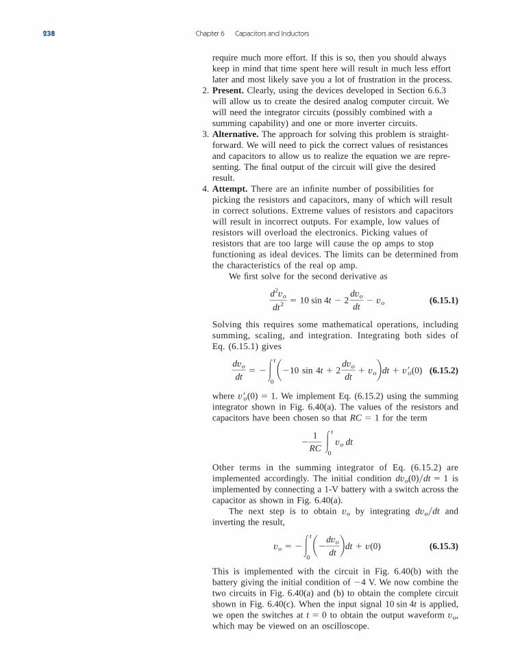
require much more effort. If this is so, then you should alwayskeep in mind that time spent here will result in much less effortlater and most likely save you a lot of frustration in the process.
2. Present. Clearly, using the devices developed in Section 6.6.3will allow us to create the desired analog computer circuit. Wewill need the integrator circuits (possibly combined with asumming capability) and one or more inverter circuits.
3. Alternative. The approach for solving this problem is straight-forward. We will need to pick the correct values of resistancesand capacitors to allow us to realize the equation we are repre-senting. The final output of the circuit will give the desiredresult.
4. Attempt. There are an infinite number of possibilities forpicking the resistors and capacitors, many of which will resultin correct solutions. Extreme values of resistors and capacitorswill result in incorrect outputs. For example, low values ofresistors will overload the electronics. Picking values ofresistors that are too large will cause the op amps to stopfunctioning as ideal devices. The limits can be determined fromthe characteristics of the real op amp.
We first solve for the second derivative as
(6.15.1)
Solving this requires some mathematical operations, includingsumming, scaling, and integration. Integrating both sides ofEq. (6.15.1) gives
(6.15.2)
where We implement Eq. (6.15.2) using the summingintegrator shown in Fig. 6.40(a). The values of the resistors andcapacitors have been chosen so that for the term
Other terms in the summing integrator of Eq. (6.15.2) areimplemented accordingly. The initial condition isimplemented by connecting a 1-V battery with a switch across thecapacitor as shown in Fig. 6.40(a).
The next step is to obtain by integrating andinverting the result,
(6.15.3)
This is implemented with the circuit in Fig. 6.40(b) with thebattery giving the initial condition of V. We now combine thetwo circuits in Fig. 6.40(a) and (b) to obtain the complete circuitshown in Fig. 6.40(c). When the input signal is applied,we open the switches at to obtain the output waveform ,which may be viewed on an oscilloscope.
vot 010 sin 4t
4
vo t
0 advo
dtb dt v(0)
dvodtvo
dvo(0)dt 1
1
RC
t
0
vo dt
RC 1
v¿o
(0) 1.
dvo
dt
t
0 a10 sin 4t 2
dvo
dt vob dt v¿o
(0)
d2vo
dt
2 10 sin 4t 2
dvo
dt vo
238 Chapter 6 Capacitors and Inductors
ale29559_ch06.qxd 07/08/2008 11:00 AM Page 238
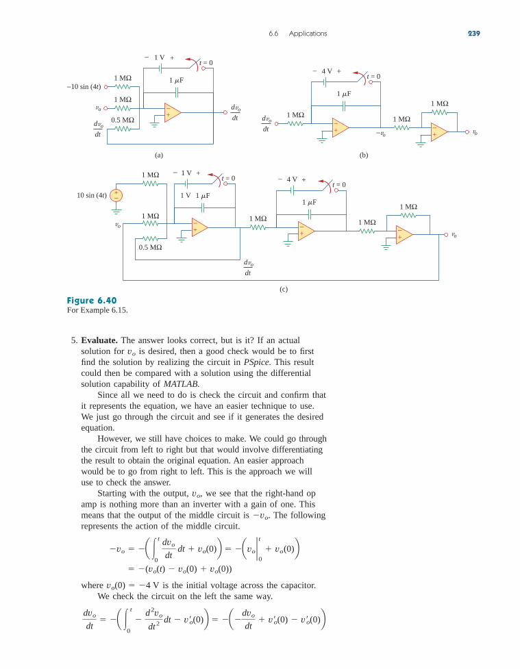
5. Evaluate. The answer looks correct, but is it? If an actualsolution for is desired, then a good check would be to firstfind the solution by realizing the circuit in PSpice. This resultcould then be compared with a solution using the differentialsolution capability of MATLAB.
Since all we need to do is check the circuit and confirm thatit represents the equation, we have an easier technique to use.We just go through the circuit and see if it generates the desiredequation.
However, we still have choices to make. We could go throughthe circuit from left to right but that would involve differentiatingthe result to obtain the original equation. An easier approachwould be to go from right to left. This is the approach we willuse to check the answer.
Starting with the output, we see that the right-hand opamp is nothing more than an inverter with a gain of one. Thismeans that the output of the middle circuit is The followingrepresents the action of the middle circuit.
where is the initial voltage across the capacitor.We check the circuit on the left the same way.
dvo
dt a
t
0
d
2vo
dt 2 dt v¿o(0)b advo
dt v¿o(0) v¿o(0)b
vo(0) 4 V
(vo(t) vo(0) vo(0))
vo a t
0
dvo
dt dt vo(0)b avo 2
0
t
vo(0)b
vo.
vo,
vo
6.6 Applications 239
(a)
1 F1 MΩ
1 V
0.5 MΩ
1 MΩdvo
dtdvo
dt
t = 0
−10 sin (4t)
vo
(b)
1 F
4 V
1 MΩ1 MΩdvo
dt
t = 0
−vovo
1 MΩ+−
+−
+−
+−
− +
1 V
dvo
dt
1 F
1 MΩ 1 V
0.5 MΩ
1 MΩ
t = 0
10 sin (4t)
vo
(c)
1 F
4 V
1 MΩ 1 MΩ
t = 0
vo
1 MΩ
+−
+−
+−
+−
+−− +
Figure 6.40For Example 6.15.
ale29559_ch06.qxd 07/08/2008 11:00 AM Page 239

Now all we need to verify is that the input to the first op amp is
Looking at the input we see that it is equal to
which does produce from the original equation.6. Satisfactory? The solution we have obtained is satisfactory. We
can now present this work as a solution to the problem.
d2vodt2
10 sin(4t) vo 1106
0.5 M dvo
dt 10 sin(4t) vo 2
dvo
dt
d 2vodt
2.
240 Chapter 6 Capacitors and Inductors
Design an analog computer circuit to solve the differential equation:
subject to ,
Answer: See Fig. 6.41, where RC 1 s.
v¿o(0) 0.vo(0) 2
d 2vo
dt 2 3
dvo
dt 2vo 4 cos 10t, t 7 0
Practice Problem 6.15
d2vo
dt2
d2vo
dt2
cos (10t)
2 Vt = 0
vo
+−
C
RR
2
R
C
R
R
R
R3
R4
+−
+−
+−
+−
+−
RR
Figure 6.41For Practice Prob. 6.15.
Summary1. The current through a capacitor is directly proportional to the time
rate of change of the voltage across it.
The current through a capacitor is zero unless the voltage is chang-ing. Thus, a capacitor acts like an open circuit to a dc source.
i C
dvdt
6.7
ale29559_ch06.qxd 07/08/2008 11:00 AM Page 240

Review Questions 241
2. The voltage across a capacitor is directly proportional to the timeintegral of the current through it.
The voltage across a capacitor cannot change instantly.3. Capacitors in series and in parallel are combined in the same way
as conductances.4. The voltage across an inductor is directly proportional to the time
rate of change of the current through it.
The voltage across the inductor is zero unless the current is chang-ing. Thus, an inductor acts like a short circuit to a dc source.
5. The current through an inductor is directly proportional to the timeintegral of the voltage across it.
The current through an inductor cannot change instantly.6. Inductors in series and in parallel are combined in the same way
resistors in series and in parallel are combined.7. At any given time t, the energy stored in a capacitor is while
the energy stored in an inductor is 8. Three application circuits, the integrator, the differentiator, and the
analog computer, can be realized using resistors, capacitors, andop amps.
12 Li2.
12 Cv2,
i 1
L
t
v dt 1
L
t
t0
v dt i(t0)
v L
di
dt
v 1
C
t
i dt 1
C
t
t0
i dt v(t0)
Review Questions
6.1 What charge is on a 5-F capacitor when it isconnected across a 120-V source?
(a) 600 C (b) 300 C
(c) 24 C (d) 12 C
6.2 Capacitance is measured in:
(a) coulombs (b) joules
(c) henrys (d) farads
6.3 When the total charge in a capacitor is doubled, theenergy stored:
(a) remains the same (b) is halved
(c) is doubled (d) is quadrupled
6.4 Can the voltage waveform in Fig. 6.42 be associatedwith a real capacitor?
(a) Yes (b) No
6.5 The total capacitance of two 40-mF series-connectedcapacitors in parallel with a 4-mF capacitor is:
(a) 3.8 mF (b) 5 mF (c) 24 mF
(d) 44 mF (e) 84 mF
021
10
−10
t
v (t)
Figure 6.42For Review Question 6.4.
ale29559_ch06.qxd 07/08/2008 11:00 AM Page 241

6.6 In Fig. 6.43, if and theelement is:
(a) a resistor (b) a capacitor (c) an inductor
v sin 4t,i cos 4t 6.9 Inductors in parallel can be combined just likeresistors in parallel.
(a) True (b) False
6.10 For the circuit in Fig. 6.44, the voltage dividerformula is:
(a) (b)
(c) (d) v1 L1
L1 L2 vsv1
L2
L1 L2 vs
v1 L1 L2
L2 vsv1
L1 L2
L1 vs
242 Chapter 6 Capacitors and Inductors
v +−
i
Element
Figure 6.43For Review Question 6.6.
6.7 A 5-H inductor changes its current by 3 A in 0.2 s. Thevoltage produced at the terminals of the inductor is:
(a) 75 V (b) 8.888 V
(c) 3 V (d) 1.2 V
6.8 If the current through a 10-mH inductor increasesfrom zero to 2 A, how much energy is stored in theinductor?
(a) 40 mJ (b) 20 mJ
(c) 10 mJ (d) 5 mJ
vs+− v2
v1
L1
L2
+
−
+ −
Figure 6.44For Review Question 6.10.
Answers: 6.1a, 6.2d, 6.3d, 6.4b, 6.5c, 6.6b, 6.7a, 6.8b,6.9a, 6.10d.
Problems
Section 6.2 Capacitors
6.1 If the voltage across a 5-F capacitor is findthe current and the power.
6.2 A capacitor has energy Determine the current through the capacitor.
6.3 Design a problem to help other students betterunderstand how capacitors work.
6.4 A current of A flows through a 2-F capacitor.Find the voltage across the capacitor given that
6.5 The voltage across a capacitor is shown inFig. 6.45. Find the current waveform.
4-mF
v(0) 1 V.v(t)
6 sin 4t
w(t) 10 cos2 377t J.20-mF
2te3t V,
6.6 The voltage waveform in Fig. 6.46 is applied acrossa capacitor. Draw the current waveformthrough it.
30-mF
0
10
−10
8642 t (ms)
v (t) V
Figure 6.45For Prob. 6.5.
v (t) V
06 8 10 1242
10
−10
t (ms)
Figure 6.46For Prob. 6.6.
6.7 At , the voltage across a 50-mF capacitor is 10 V.Calculate the voltage across the capacitor for when current 4t mA flows through it.
6.8 A 4-mF capacitor has the terminal voltage
If the capacitor has an initial current of 2 A, find:
(a) the constants A and B,
(b) the energy stored in the capacitor at
(c) the capacitor current for t 7 0.
t 0,
v b 50 V, t 0
Ae100t Be600t V, t 0
t 7 0t 0
ale29559_ch06.qxd 07/08/2008 11:00 AM Page 242
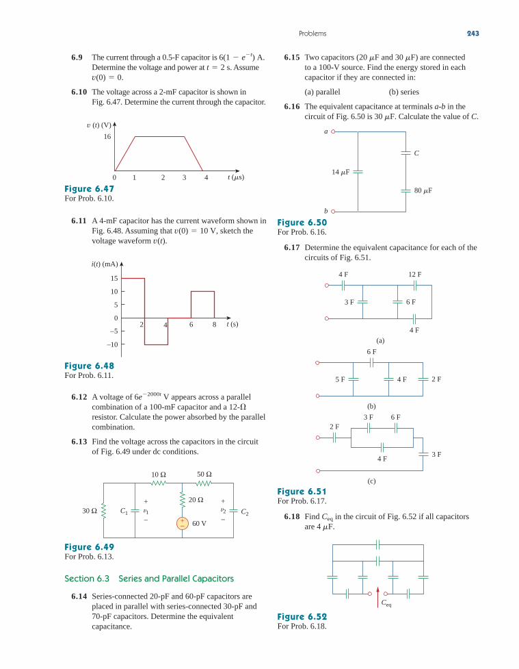
6.9 The current through a 0.5-F capacitor is Determine the voltage and power at Assume
6.10 The voltage across a 2-mF capacitor is shown inFig. 6.47. Determine the current through the capacitor.
v(0) 0.t 2 s.
6(1 et) A. 6.15 Two capacitors ( and ) are connected to a 100-V source. Find the energy stored in eachcapacitor if they are connected in:
(a) parallel (b) series
6.16 The equivalent capacitance at terminals a-b in thecircuit of Fig. 6.50 is Calculate the value of C.30 mF.
30 mF20 mF
Problems 243
16
0 1 2 3 4
v (t) (V)
t (s)
Figure 6.47For Prob. 6.10.
6.11 A 4-mF capacitor has the current waveform shown inFig. 6.48. Assuming that sketch thevoltage waveform v(t).
v(0) 10 V,
i(t) (mA)
08642
15
10
5
−5
−10
t (s)
Figure 6.48For Prob. 6.11.
6.12 A voltage of appears across a parallelcombination of a 100-mF capacitor and a resistor. Calculate the power absorbed by the parallelcombination.
6.13 Find the voltage across the capacitors in the circuitof Fig. 6.49 under dc conditions.
12-6e2000t V
30 Ω
60 V
20 Ω
10 Ω 50 Ω
v2v1C1 C2+−
+
−
+
−
Figure 6.49For Prob. 6.13.
Section 6.3 Series and Parallel Capacitors
6.14 Series-connected 20-pF and 60-pF capacitors areplaced in parallel with series-connected 30-pF and70-pF capacitors. Determine the equivalentcapacitance.
14 F
80 F
C
a
b
Figure 6.50For Prob. 6.16.
6.17 Determine the equivalent capacitance for each of thecircuits of Fig. 6.51.
4 F
4 F
6 F3 F
12 F
(a)
6 F
4 F 2 F5 F
(b)
2 F
3 F
(c)
6 F3 F
4 F
Figure 6.51For Prob. 6.17.
6.18 Find in the circuit of Fig. 6.52 if all capacitorsare 4 mF.
Ceq
Ceq
Figure 6.52For Prob. 6.18.
ale29559_ch06.qxd 07/08/2008 11:00 AM Page 243

6.19 Find the equivalent capacitance between terminalsa and b in the circuit of Fig. 6.53. All capacitancesare in mF.
6.23 Using Fig. 6.57, design a problem that will helpother students better understand how capacitors worktogether when connected in series and in parallel.
244 Chapter 6 Capacitors and Inductors
12
12
40
80
5030
20
60
10
a
b
Figure 6.53For Prob. 6.19.
6.20 Find the equivalent capacitance at terminals a-b ofthe circuit in Fig. 6.54.
3 F
2 F 2 F 2 F
1 F 1 F
3 F 3 F 3 F
b
a
Figure 6.54For Prob. 6.20.
6.21 Determine the equivalent capacitance at terminalsa-b of the circuit in Fig. 6.55.
6 F 4 F5 F
3 F 12 F2 F
a
b
Figure 6.55For Prob. 6.21.
6.22 Obtain the equivalent capacitance of the circuit inFig. 6.56.
40 F
20 F
ba
35 F 5 F
10 F
15 F 15 F
10 F
Figure 6.56For Prob. 6.22.
C2
C3
C1
C4
+−V
Figure 6.57For Prob. 6.23.
6.24 Repeat Prob. 6.23 for the circuit of Fig. 6.58.
60 F 20 F
14 F 80 F30 F+−90 V
Figure 6.58For Prob. 6.24.
6.25 (a) Show that the voltage-division rule for twocapacitors in series as in Fig. 6.59(a) is
assuming that the initial conditions are zero.
v1 C2
C1 C2 vs, v2
C1
C1 C2 vs
C1is C2
(b)
C1
vs
v1
v2 C2
(a)
+−
+
−
+ − i1 i2
Figure 6.59For Prob. 6.25.
ale29559_ch06.qxd 07/08/2008 11:00 AM Page 244

(b) For two capacitors in parallel as in Fig. 6.59(b),show that the current-division rule is
assuming that the initial conditions are zero.
6.26 Three capacitors, andare connected in parallel across a
150-V source. Determine:
(a) the total capacitance,
(b) the charge on each capacitor,
(c) the total energy stored in the parallelcombination.
6.27 Given that four capacitors can be connected inseries and in parallel, find the minimum andmaximum values that can be obtained by suchseries/parallel combinations.
*6.28 Obtain the equivalent capacitance of the networkshown in Fig. 6.60.
4-mF
C3 20 mF,C1 5 mF, C2 10 mF,
i1 C1
C1 C2 is, i2
C2
C1 C2 is
6.30 Assuming that the capacitors are initially uncharged,find in the circuit of Fig. 6.62.vo(t)
Problems 245
30 F
20 F10 F
50 F40 F
Figure 6.60For Prob. 6.28.
6.29 Determine for each circuit in Fig. 6.61.Ceq
C
CC
C
CCeq
(a)
C
CC
C
Ceq
(b)
Figure 6.61For Prob. 6.29.
* An asterisk indicates a challenging problem.
Figure 6.62For Prob. 6.30.
6.32 In the circuit of Fig. 6.64, let andDetermine: (a)
and (b) the energy in each capacitor att 0.5 s.
v2(t),v1(t)v1(0) 50 V, v2(0) 20 V.
is 30e2t mA
Figure 6.63For Prob. 6.31.
Figure 6.64For Prob. 6.32.
is +
−vo(t)
6 F
3 F
is (mA)
021
60
t (s)
6.31 If find and in the circuit ofFig. 6.63.
i2(t)v(t), i1(t),v(0) 0,
i1
is
i2
v6 F 4 F
is (mA)
53 41 2
20
0
−20
t
+
−
v1
v220 F
12 F
40 Fis
+ –
+
–
ale29559_ch06.qxd 07/08/2008 11:00 AM Page 245

6.33 Obtain the Thevenin equivalent at the terminals, a-b,of the circuit shown in Fig. 6.65. Please note thatThevenin equivalent circuits do not generally existfor circuits involving capacitors and resistors. This isa special case where the Thevenin equivalent circuitdoes exist.
6.41 The voltage across a 2-H inductor is If the initial current through the inductor is 0.3 A,find the current and the energy stored in the inductorat
6.42 If the voltage waveform in Fig. 6.67 is appliedacross the terminals of a 10-H inductor, calculate thecurrent through the inductor. Assume i(0) 1 A.
t 1 s.
20 (1 e2t) V.
246 Chapter 6 Capacitors and Inductors
3 F
15 V
2 F
5 F
a
b
−+
Figure 6.65For Prob. 6.33.
Section 6.4 Inductors
6.34 The current through a 10-mH inductor is Find the voltage and the power at
6.35 An inductor has a linear change in current from50 mA to 100 mA in 2 ms and induces a voltage of160 mV. Calculate the value of the inductor.
6.36 Design a problem to help other students betterunderstand how inductors work.
6.37 The current through a 12-mH inductor is Find the voltage, across the inductor for
and the energy stored at
6.38 The current through a 40-mH inductor is
Find the voltage
6.39 The voltage across a 200-mH inductor is given by
Determine the current through the inductor.Assume that
6.40 The current through a 10-mH inductor is shown inFig. 6.66. Determine the voltage across the inductorat and 5 ms.t 1, 3,
i(0) 1 A.i(t)
v(t) 3t2 2t 4 V for t 7 0.
v(t).
i(t) b 0, t 6 0
te2t A, t 7 0
t p200 s.p200 s,
0 6 t 64 sin 100t A.
t 3 s.6et2 A.
042
20
6 t (ms)
i(t) (A)
Figure 6.66For Prob. 6.40.
v (t) (V)
5421 3
30
0t
Figure 6.67For Prob. 6.42.
6.43 The current in an 80-mH inductor increases from 0to 60 mA. How much energy is stored in theinductor?
*6.44 A 100-mH inductor is connected in parallel with aresistor. The current through the inductor is
(a) Find the voltage acrossthe inductor. (b) Find the voltage across theresistor. (c) Does (d) Calculatethe energy in the inductor at
6.45 If the voltage waveform in Fig. 6.68 is applied to a50-mH inductor, find the inductor current Assume i(0) 0.
i(t).
t 0.vR(t) vL(t) 0?
vR
vLi(t) 50e400t mA.2-k
v (t) (V)
021
10
–10
t
Figure 6.68For Prob. 6.45.
6.46 Find and the energy stored in the capacitorand inductor in the circuit of Fig. 6.69 under dcconditions.
vC, iL,
5 Ω
2 Ω
4 Ω
2 F
6 A 0.5 H
vC
+
−
iL
Figure 6.69For Prob. 6.46.
ale29559_ch06.qxd 07/08/2008 11:00 AM Page 246
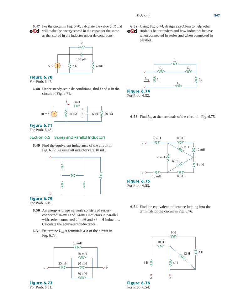
6.47 For the circuit in Fig. 6.70, calculate the value of R thatwill make the energy stored in the capacitor the sameas that stored in the inductor under dc conditions.
6.52 Using Fig. 6.74, design a problem to help otherstudents better understand how inductors behavewhen connected in series and when connected inparallel.
Problems 247
R
2 Ω5 A 4 mH
160 F
Figure 6.70For Prob. 6.47.
6.48 Under steady-state dc conditions, find i and in thecircuit of Fig. 6.71.
v
10 mA 30 kΩ 6 F 20 kΩ
2 mHi
v+
−
Figure 6.71For Prob. 6.48.
Section 6.5 Series and Parallel Inductors
6.49 Find the equivalent inductance of the circuit inFig. 6.72. Assume all inductors are 10 mH.
Figure 6.72For Prob. 6.49.
6.50 An energy-storage network consists of series-connected 16-mH and 14-mH inductors in parallelwith series-connected 24-mH and 36-mH inductors.Calculate the equivalent inductance.
6.51 Determine at terminals a-b of the circuit inFig. 6.73.
Leq
60 mH
20 mH
30 mH
25 mH
10 mH
a b
Figure 6.73For Prob. 6.51.
L4
L2 L3
L5L1L6
Leq
Figure 6.74For Prob. 6.52.
6.53 Find at the terminals of the circuit in Fig. 6.75.Leq
8 mH6 mH
8 mH
12 mH
4 mH6 mH
5 mH
8 mH10 mH
a
b
Figure 6.75For Prob. 6.53.
6.54 Find the equivalent inductance looking into theterminals of the circuit in Fig. 6.76.
9 H
6 H4 H
3 H12 H
10 H
a b
Figure 6.76For Prob. 6.54.
ale29559_ch06.qxd 07/08/2008 11:00 AM Page 247

6.55 Find in each of the circuits in Fig. 6.77.Leq
6.59 (a) For two inductors in series as in Fig. 6.81(a),show that the voltage division principle is
assuming that the initial conditions are zero.
(b) For two inductors in parallel as in Fig. 6.81(b),show that the current-division principle is
assuming that the initial conditions are zero.
i1 L2
L1 L2 is, i2
L1
L1 L2 is
v1 L1
L1 L2 vs, v2
L2
L1 L2 vs
248 Chapter 6 Capacitors and Inductors
Leq
(a)
L
LL
L
L
Leq
L
L
L L
L
(b)
Figure 6.77For Prob. 6.55.
6.56 Find in the circuit of Fig. 6.78.Leq
L
L
L
L L
Leq
L
LL
Figure 6.78For Prob. 6.56.
*6.57 Determine that may be used to represent theinductive network of Fig. 6.79 at the terminals.
Leq
3 H
4 H
5 HLeq
+ −i
a
b
dtdi2
Figure 6.79For Prob. 6.57.
6.58 The current waveform in Fig. 6.80 flows through a3-H inductor. Sketch the voltage across the inductorover the interval 0 6 t 6 6 s.
i(t)
0
2
3 4 5 621 t
Figure 6.80For Prob. 6.58.
vs+−
+
−v2
+ −v1
L1
L2
(a)
is L1 L2
(b)
i1 i2
Figure 6.81For Prob. 6.59.
6.60 In the circuit of Fig. 6.82, Determineand for t 7 0.vo(t)io(t)
io(0) 2 A.
3 H 5 H
io (t)
4e–2t V+
−vo
Figure 6.82For Prob. 6.60.
ale29559_ch06.qxd 07/08/2008 11:00 AM Page 248

6.62 Consider the circuit in Fig. 6.84. Given thatfor and
find: (a) (b) and i2(t).i1(t)i2(0),i1(0) 10 mA,t 7 0v(t) 12e3t mV
6.65 The inductors in Fig. 6.87 are initially charged and areconnected to the black box at If
and find:
(a) the energy initially stored in each inductor,
(b) the total energy delivered to the black box fromto
(c) and
(d) i(t), t 0.
i2(t), t 0,i1(t)
t ,t 0
v(t) 50e200t mV, t 0,i2(0) 2 A,i1(0) 4 A,t 0.
Problems 249
6.61 Consider the circuit in Fig. 6.83. Find: (a) and if (b) (c) energy storedin the 20-mH inductor at t 1 s.
vo(t),is 3et mA,i2(t)Leq, i1(t),
is 20 mH
4 mH
6 mH
i2i1
Leq
+vo
–
Figure 6.83For Prob. 6.61.
25 mH
60 mH20 mHv(t)
+
–
i2(t)i1(t)
Figure 6.84For Prob. 6.62.
6.63 In the circuit of Fig. 6.85, sketch vo.
+2 H i2(t)i1(t)
i1(t) (A)
vo–
3
0 3 6
i2(t) (A)
t (s)t (s)
4
0 2 4 6
Figure 6.85For Prob. 6.63.
t = 0
5 Ω+
–
4 Ω B
0.5 H40 V 20 A
i
v+–
A
Figure 6.86For Prob. 6.64.
i1 i2
20 H5 Hv
+
−
Black box
i(t)
t = 0
Figure 6.87For Prob. 6.65.
6.66 The current i(t) through a 40-mH inductor is equal,in magnitude, to the voltage across it for all values oftime. If find i(t).
Section 6.6 Applications
6.67 An op amp integrator has and If the input voltage is
obtain the output voltage.vi 10 sin 50t mV,0.01 mF.
C R 100 k
i(0) 5 A,
6.64 The switch in Fig. 6.86 has been in position A for along time. At the switch moves from positionA to B. The switch is a make-before-break type sothat there is no interruption in the inductor current.Find: (a) for (b) just after the switch hasbeen moved to position B, (c) long after theswitch is in position B.
v(t)vt 6 0,i(t)
t 0,
ale29559_ch06.qxd 07/08/2008 11:00 AM Page 249

6.68 A 10-V dc voltage is applied to an integrator withat How long will it
take for the op amp to saturate if the saturationvoltages are and Assume that theinitial capacitor voltage was zero.
6.69 An op amp integrator with andhas the input waveform shown in
Fig. 6.88. Plot the output waveform.C 1 mF
R 4 M
12 V?12 V
t 0.R 50 k, C 100 mF
6.75 An op amp differentiator has and The input voltage is a ramp
Find the output voltage.
6.76 A voltage waveform has the following characteristics:a positive slope of 20 V/s for 5 ms followed by anegative slope of 10 V/s for 10 ms. If the waveformis applied to a differentiator with
sketch the output voltage waveform.C 10 mF,R 50 k,
r(t) 12t mV.10 mF.C R 250 k
250 Chapter 6 Capacitors and Inductors
1 V
2 F
10 kΩ20 kΩ
vo
+−
0.5 F
+
−
+−
+−
Figure 6.89For Prob. 6.72.
6.70 Using a single op amp, a capacitor, and resistors ofor less, design a circuit to implement
Assume at
6.71 Show how you would use a single op amp to generate
If the integrating capacitor is obtain theother component values.
6.72 At calculate due to the cascadedintegrators in Fig. 6.89. Assume that the integratorsare reset to 0 V at t 0.
vot 1.5 ms,
C 2 mF,
vo t
0 (v1 4v2 10v3) dt
t 0.vo 0
vo 50 t
0
vi(t) dt
100 k
vo
vi+−
+
−
R
R
R
C
R
+−
Figure 6.90For Prob. 6.73.
(a)
vi(t)
0
2
3 421 t (s)
−2
vovi
+−
+
−
100 kΩ
0.01 F
(b)
+−
Figure 6.91For Prob. 6.74.
vi (mV)
0
20
10
–10
–20
3 4 5 621 t (ms)
Figure 6.88For Prob. 6.69.
6.74 The triangular waveform in Fig. 6.91(a) is applied tothe input of the op amp differentiator in Fig. 6.91(b).Plot the output.
6.73 Show that the circuit in Fig. 6.90 is a noninvertingintegrator.
ale29559_ch06.qxd 07/08/2008 11:00 AM Page 250

*6.77 The output of the op amp circuit in Fig. 6.92(a) isshown in Fig. 6.92(b). Let and
Determine the input voltage waveformand sketch it.C 1 mF.
Ri Rf 1 Mvo
6.81 Design an analog computer to simulate the followingequation:
6.82 Design an op amp circuit such that
where and are the input voltage and outputvoltage, respectively.
vovs
vo 10vs 2 vs dt
d 2v
dt 2 5v 2f (t)
Comprehensive Problems 251
(b)
(a)
0
4
3 421 t (s)
−4
vov i
vo
Ri
C
Rf
+−
+
−
+−
Figure 6.92For Prob. 6.77.
6.78 Design an analog computer to simulate
where and v¿0(0) 0.v0(0) 2
d 2vo
dt 2 2
dvo
dt vo 10 sin 2t
vo(t)
−f (t)
1 F1 F
1 MΩ1 MΩ
1 MΩ
100 kΩ 200 kΩ
500 kΩ
100 kΩ
+−
+−
+−
+−
Figure 6.93For Prob. 6.80.
6.79 Design an analog computer circuit to solve thefollowing ordinary differential equation.
where
6.80 Figure 6.93 presents an analog computer designedto solve a differential equation. Assuming isknown, set up the equation for f (t).
f (t)
y(0) 1 V.
dy(t)
dt 4y(t) f (t)
Comprehensive Problems
6.83 Your laboratory has available a large number ofcapacitors rated at 300 V. To design a
capacitor bank of rated at 600 V, how manycapacitors are needed and how would you
connect them?10-mF
40 mF10-mF
6.84 An 8-mH inductor is used in a fusion powerexperiment. If the current through the inductor is
find the power beingdelivered to the inductor and the energy stored in itat t 0.5 s.
i(t) 5 sin2 p t mA, t 7 0,
ale29559_ch06.qxd 07/08/2008 11:00 AM Page 251

6.85 A square-wave generator produces the voltagewaveform shown in Fig. 6.94(a). What kind of acircuit component is needed to convert the voltagewaveform to the triangular current waveform shownin Fig. 6.94(b)? Calculate the value of thecomponent, assuming that it is initially uncharged.
6.86 An electric motor can be modeled as a seriescombination of a resistor and 200-mH inductor.If a current flows through the seriescombination, find the voltage across the combination.
i(t) 2te10t A12-
252 Chapter 6 Capacitors and Inductors
v (V)
0
5
−5
3 421 t (ms)
(a)
(b)
i (A)
4
3 4210 t (ms)
Figure 6.94For Prob. 6.85.
ale29559_ch06.qxd 07/08/2008 11:00 AM Page 252