File Room Document Transmittal Sheet - 6 Feb 2017 14:55
192
File Room Document Transmittal Sheet Hazardous Waste Section 17 Your Name: Rob McDaniel Facility Name: Apex Tool Group Document Group: Corrective Action (CA) Document Type: RCRA Facility Investigation (RFI) Description: Revised Additional RCRA Facility Investigation Work Plan Date of Doc: 9/6/2016 Author of Doc: Vicki Garlington and Jay Bennett NCD042892067 EPA ID: Date Recieved by File Room: Month File Room Use Only Date Scanned: Scanner's Initials: Day Year NCD042892067
-
Upload
khangminh22 -
Category
Documents
-
view
1 -
download
0
Transcript of File Room Document Transmittal Sheet - 6 Feb 2017 14:55
File Room Document Transmittal Sheet
Hazardous Waste Section
17
Your Name: Rob McDaniel
Facility Name: Apex Tool Group
Document Group: Corrective Action (CA)
Document Type: RCRA Facility Investigation (RFI)
Description: Revised Additional RCRA Facility Investigation Work Plan
Date of Doc: 9/6/2016
Author of Doc: Vicki Garlington and Jay Bennett
NCD042892067EPA ID:
Date Recieved by File Room:
MonthFile Room Use Only
Date Scanned:
Scanner's Initials:
Day YearNCD042892067
Amec Foster Wheeler Environment & Infrastructure, Inc. Tel – (919) 381-9900 4021 Stirrup Creek Drive, Suite 100 Fax – (919) 381-9901 Durham, North Carolina 27703 www.amecfw.com Licensure: NC Engineering F-1253; NC Geology C-247
©2016 Amec Foster Wheeler. All Rights Reserved.
September 6, 2016 Robert McDaniel Hydrogeologist Division of Waste Management North Carolina Department of Environmental Quality (NC DEQ) 217 West Jones Street Raleigh, North Carolina 27699-1646 Subject: Response to North Carolina Department of Environmental Quality Comments Additional RCRA Facility Investigation Work Plan Apex Tool Group, LLC Apex, North Carolina NCD 042 892 067 Dear Mr. McDaniel: On August 16, 2016, the North Carolina Department of Environmental Quality (NC DEQ) issued a comment letter to Apex Tool Group, LLC (ATG) for an Additional Resource Conservation and Recovery Act (RCRA) Facility Investigation (RFI) Work Plan submitted to the NC DEQ on July 13, 2016 for the ATG facility located at 1000 Lufkin Road in Apex, North Carolina (the Facility). Amec Foster Wheeler Environment & Infrastructure, Inc. (Amec Foster Wheeler) has prepared the enclosed letter to respond and address comments issued by the NC DEQ on behalf of ATG. This response also serves as cover letter to the enclosed Additional RFI Work Plan (Revision 1). If you should have questions or concerns regarding the enclosed information, please feel free to contact the undersigned at (919) 381-9900. Thank you again for your assistance and we look forward to working with your team as we move forward.
Amec Foster Wheeler Environment & Infrastructure, Inc.
Vicki Garlington Jay Bennett, PG, RSM Senior Project Manager/Geoscientist Associate Hydrogeologist/Senior
Project Manager ATG Program Manager ec. Matthew Somers, Corporate Environmental Compliance Manager, ATG Darrell Bradfield, Regional EHS Leader, ATG Michael Beltran, OpEx, ATG Enclosure
Response to North Carolina Department of Environmental Quality Comments Additional RFI Work Plan ATG, Apex, NC September 6, 2016 Page 2
Section 5.2.1 Soil Screening and Analysis. Comment 1. Additional information is needed for the determination of background soil
concentrations of naturally occurring constituents at the Apex Tool Group site. Attached is guidance document (Guidance for the Determination and Comparison of Background Concentrations of Naturally Occurring Constituents in Soil) that can be used to evaluate the background concentrations of naturally occurring constituents in soil to determine if there is a statistically significant difference between background data set and a confirmation data set of samples collect at a SWMU or AOC.
Comment 1. Response 1. In the July 13, 2016 Additional RFI Work Plan, ATG had proposed to install
three background boring locations from which two soil samples per boring (a shallow and deep soil sample) were to be collected. This would allow for the statistical analysis of six random soil samples (three in shallow and three in deep soil intervals). To meet the minimum number of random soil samples recommended in the abovementioned Guidance, ATG has amended the scope of work detailed in Section 5.2.1 to include nine additional background boring locations from which a shallow and deep soil sample will be collected. The text also has been modified, indicating that the recommended Guidance will be utilized to statistically evaluate background concentrations of naturally occurring constituents. This will include the use of ProUCL version 5.1.002 (5.1) or similar program to determine if soil sample results are statistically greater than background concentrations. RFI Work Plan Tables and Figures have been amended accordingly.
Comment 2 EPA SW846 Method 5035 sampling protocol should be used to collect soil
samples that are to be analyzed for volatile organic compounds as outlined in EPA Region 4 Soil Sampling guidance document (https://www.epa.gov/sites/production/files/2015-06/documents/Soil-Sampling.pdf).
Comment 2. Response 1. Although not specifically stated in the Additional RFI Work Plan text, EPA
SW846 Method 5053 is a standard sampling protocol implemented by Amec Foster Wheeler when volatile organic compounds are being evaluated in soil. The text in Section 5.2.1 has, however, been amended to explicitly call out this sampling method and the EPA Region 4 Soil Sampling Guidance has been added to the Standard Operating Procedures available in the Additional RFI Work Plan Appendix B.
Comment 3. This section should include a discussion of the actions Apex Tool Group
will take if the analytical method detection limit cannot be met for hexavalent chromium. In addition, this section should also include a brief discussion of the actions Apex Tool Group will take if the concentration of hexavalent chromium exceeds the screening levels.
Response to North Carolina Department of Environmental Quality Comments Additional RFI Work Plan ATG, Apex, NC September 6, 2016 Page 3
Comment 3. Response 1. Prism Laboratories, Inc., the laboratory we intend to use for the analysis of
hexavalent chromium in soil has indicated that the current laboratory reporting limit and method detection limit for hexavalent chromium are 0.4 milligrams per kilogram (mg/kg) and 0.16 mg/kg, respectively. Soil samples will be analyzed using SW-846 Method 3060A alkaline digestion coupled EPA Method 7196A in order to achieve low detection limits as recommended in Inactive Hazardous Site Branch (IHSB) Guidelines for Assessment and Cleanup (NC DEQ, 2015).
Comment 3. Response 2. Text in the Additional RFI Work Plan has been amended, indicating that
ATG will notify NC DEQ within 48 hours of confirmation of results of hexavalent chromium results in excess of the NCDEQ Preliminary Soil Remediation Goals (PSRG) in soil. Following notification an Interim Measures Work Plan will be prepared and submitted to the NC DEQ in accordance with Part V.G. of the RCRA Permit as necessary. It is assumed that direct contact associated with potentially impacted soil will be minimized due to the presence of an approximate eight-inch concrete slab. In addition, based on historical assessments performed at the facility by others no public or private water wells are known to exist within a 1,000 foot radius of the Facility. Therefore, the two most likely pathways to receptors are more than likely incomplete.
Section 5.2.2 Groundwater Well Installation. Comment 1. The filter pack for groundwater monitoring wells should extend a minimum
of two feet above the top of the well screen. Comment 1. Response 1. Due to the potential presence of metals in groundwater, and in order to
reduce the potential for total suspended solids during sampling, ATG has elected to install pre-packed monitoring wells rather than constructing monitoring wells in the field as originally proposed in the Additional RFI Work Plan dated July 13, 2016. Pre-packed wells will provide a level of certainty that the sand pack will be located directly around the well screen to allow for representative samples of the aquifer and decrease the potential for suspended solids. Remaining annular space around the well will be backfilled with filter pack in accordance with EPA’s Handbook of Suggested Practices for the Design and Installation of Ground-Water Monitoring Wells (March 1991) and 15A NCAC 02C .0108 and will extend two-feet above the top of the well screen. Text in the Additional RFI Work Plan has been amended accordingly.
Comment 2. The bentonite seal should extend, at a minimum, two feet above the filter
pack and should be fully hydrated prior to the installation of the bentonite/cement grout in the annular space.
Response to North Carolina Department of Environmental Quality Comments Additional RFI Work Plan ATG, Apex, NC September 6, 2016 Page 4
Comment 2. Response 1 A well seal, meeting EPA and ASTM D-5092 method requirements, will be
installed a minimum of two feet above the filter pack in accordance with EPA’s Handbook of Suggested Practices for the Design and Installation of Ground-Water Monitoring Wells (March 1991) and 15A NCAC 02C .0108. Text in the Additional RFI Work Plan has been amended accordingly.
Section 5.2.3 Groundwater Sample Collection and Analysis. Comment 1. Wells installed with air rotary or developed with stressful measures should
not be sampled for volatile organic compounds until a representative sample of the aquifer groundwater can be collected.
Comment 1. Response 1. ATG has elected to install monitoring wells using direct push technology
(DPT) with the capability to turn augers, rather than using air rotary methods as originally proposed in the July 13, 2016 Additional RFI Work Plan. Additionally, as previously discussed, monitoring wells will be constructed of pre-packed well screens. The use of DPT, over more aggressive air rotary methods, should reduce the disturbance of natural formation conditions. The use of pre-packed wells should reduce the necessity to use stressful well development measures. In addition to modifications in drilling methods and well construction, groundwater sampling will not commence until one week has passed following well development to allow aquifer parameters to normalize. Text in the Additional RFI Work Plan has been amended to reflect these changes.
Comment 2. This section should include a discussion of procedure to be used to collect
the groundwater samples. The procedures outlined in “Monitoring Well Sampling Using a Pump Standard Operating Procedures #011” in Appendix B are very generic.
Comment 2. Response 1. The text in the Additional RFI Work Plan has been amended to provide
more specific groundwater low flow sampling procedures. Additionally, the procedures outlined in “Monitoring Well Sampling Using a Pump Standard Operating Procedures #011” which were previously provided in Appendix B of the July 13, 2016 Additional RFI Work Plan have been replaced by Low Stress (Low Flow) Purging and Sampling Procedure for the Collection of Groundwater Samples from Monitoring Wells – EQASOP-GW 001 (U.S. EPA, 2010).
Comment 3. Apex Tool Group should include a discussion of the statistical method to
be used to determine if the groundwater has been impacted by a release from a SWMU that exceeds background concentrations.
Comment 3. Response 1. For the Additional RFI revision, ATG proposes to install a minimum of ten
background groundwater monitoring wells (rather than three as originally
Response to North Carolina Department of Environmental Quality Comments Additional RFI Work Plan ATG, Apex, NC September 6, 2016 Page 5
proposed in the July 13, 2016 Additional RFI Work Plan). ATG realizes that more than one sampling event will be necessary from the ten background wells in order to establish a trend over the course of time (to account for seasonal fluctuations and changes in the aquifer system), and to establish an appropriate data set from which to perform a statistical analysis. In light of the fact that ATG’s RCRA Permit renewal application is due in January 2017, ATG proposes to use the groundwater data collected from background wells during this Additional RFI to establish a preliminary data set, only. If it is determined that additional background evaluations are necessary the SWMU, AOC and preliminary background groundwater data set will be used to determine which statistical method should be used under §264.97(h) and §258.53(g) to evaluate groundwater monitoring data per hazardous constituent. The statistical method will be identified in ATG’s RCRA Permit renewal application and additional background sampling will performed as necessary in accordance with U.S. EPA Statistical Analysis of Groundwater Monitoring Data at RCRA Facilities – Unified Guidance (March, 2009).
Section 5.3 Interim Remedial Action – AOC-E. Comment 1. If interim remedial measures at the Former Interior Production Area (AOC-
E) are determined to be necessary, Apex Tool Group should specify the action that would be included in the interim remedial measures and an explanation for the actions. The procedures for interim measures, outlined in Part V.G. Interim Measures in the Post-Closure Permit, should be followed.
Comment 1. Response 1. If interim remedial measures are determined to be necessary in the Former
Interior Production Area (AOC-E), ATG will follow the procedures outlined in Part V.G. Interim Measures in the Post-Closure Permit. ATG anticipates two courses of Interim Measures may be implemented based on the results – either removal of concrete and excavation of impacted material or encapsulation using a membrane material or geotextile application and installation of a concrete slab on top of the membrane/geotextile application.
Section 5.5 Investigation Derived Waste. Comment 1. With the generation of investigation derived waste during the installation
and sampling of the groundwater monitoring wells and the collection of soil samples, Apex Tool Group should use the EPA guidance document “Management of Investigation Derived Waste” for procedures and management of waste generated during the implementation of the work plan. This guidance document can be found at www.epa.gov/sites/production/files/2015-06/documents/Managment-of-IDW.pdf.
Comment 1. Response 1. Apex Tool Group will use EPA guidance document “Management of
Response to North Carolina Department of Environmental Quality Comments Additional RFI Work Plan ATG, Apex, NC September 6, 2016 Page 6
Investigation Derived Waste” (U.S. EPA, 2014), to manage IDW generated during the Additional RFI including but not limited to PPE, soil cuttings, groundwater purge/development water, decontamination water. In general it is anticipated that IDW will be placed in 55-gallon drums (labeled with contents), stored in the Facility’s drum storage area (a covered shed located adjacent to the waste water treatment plant), analyzed for appropriate waste characterization parameters and manifested and shipped to a permitted treatment or disposal facility within 90 days of generation (if it is deemed hazardous). The text in the Additional RFI Work Plan has been amended to include a reference to the EPA guidance document and the guidance document has been added to the Additional RFI Work Plan Standard Operating Procedures presented in Appendix B.

ADDITIONAL RESOURCE CONSERVATION RECOVERY ACT FACILITY INVESTIGATION WORK PLAN (REVISION 1) Apex Tool Group Facility 1000 Lufkin Road Apex, North Carolina EPA ID: NCD 042 892 067 Prepared for: Apex Tools Group, LLC 1000 Lufkin Road Apex, North Carolina 27539 Prepared by: Amec Foster Wheeler Environment & Infrastructure, Inc. 4021 Stirrup Creek Drive, Suite 100 Durham, North Carolina 27703 September 6, 2016 Project No. 6480166011
Copyright © 2016 by Amec Foster Wheeler Environment & Infrastructure, Inc.
All rights reserved.
Amec Foster Wheeler Environment & Infrastructure, Inc. Tel – (919) 381-9900 4021 Stirrup Creek Drive, Suite 100 Fax – (919) 381-9901 Durham, North Carolina 27703 www.amecfw.com Licensure: NC Engineering F-1253; NC Geology C-247 ©2016 Amec Foster Wheeler. All Rights Reserved.
September 6, 2016 Mr. Robert McDaniel Hydrogeologist Hazardous Waste Section, Division of Waste Management Department of Environmental Quality 3800 Barrett Drive Raleigh, NC 27609 Subject: ADDITIONAL RESOURCE CONSERVATION RECOVERY ACT FACILITY INVESTIGATION WORK PLAN (REVISION 1)
APEX TOOL GROUP FACILITY APEX, NORTH CAROLINA EPA ID: NCD 042 892 067 Dear Mr. McDaniel: On behalf of Apex Tool Group, LLC (ATG), Amec Foster Wheeler Environment & Infrastructure, Inc. (Amec Foster Wheeler) is pleased to present the enclosed Additional Resource Conservations Recovery Act (RCRA) Facility Investigation (RFI) Work Plan (WP) (Revision 1 [REV 1]) for the above-referenced Facility located at 1000 Lufkin Road in Apex, Wade County, North Carolina. If you have questions or desire further information, please feel free to contact us at (919) 381-9900. Respectfully submitted, Amec Foster Wheeler Environment & Infrastructure, Inc.
Vicki A. Garlington Jay Bennett, PG, RSM Senior Project Manager Associate Hydrogeologist ec. Matthew Somers, Corporate Environmental Compliance Manager, ATG
Michael Beltran, Regional EHS Leader, ATG Darrell Bradfield, OpEx, ATG
Enclosure
Additional RCRA Facility Investigation Work Plan (REV 1) Apex Tools Group Facility Apex, North Carolina
Amec Foster Wheeler
Project No.: 6480166011 September 6, 2016 Page i
TABLE OF CONTENTS
Page
1.0 INTRODUCTION .................................................................................................................. 1
1.1 Purpose and Objectives .................................................................................................... 1 1.2 Additional RFI WP Organization ....................................................................................... 1
2.0 BACKGROUND ................................................................................................................... 2
2.1 Site Operations ................................................................................................................. 2 2.2 RCRA Permit .................................................................................................................... 2 2.3 Historical Facility Processes ............................................................................................. 4 2.4 Historical RFI Activities ..................................................................................................... 4
3.0 FACILTIY SETTINGS .......................................................................................................... 6
3.1 Physiography and Topography ......................................................................................... 6 3.2 Geology and Soils ............................................................................................................. 6 3.3 Hydrogeology .................................................................................................................... 7
4.0 PROJECT MANAGEMENT PLAN ...................................................................................... 7
5.0 ADDITIONAL RFI ACTVITIES ............................................................................................. 8
5.1 Utility Location................................................................................................................... 9 5.2 Subsurface Investigation .................................................................................................. 9
5.2.1 Soil Screening and Analysis ................................................................................ 10 5.2.2 Groundwater Well Installation .............................................................................. 11 5.2.3 Groundwater Sample Collection and Analysis ..................................................... 12
5.3 Interim Remedial Action – AOC-E .................................................................................. 13 5.4 Decontamination Procedures ......................................................................................... 13 5.5 Investigation Derived Waste ........................................................................................... 14
6.0 QUALITY ASSURANCE/QUALITY CONTROL PROCEDURES ..................................... 14
6.1 Quality Assurance/Quality Control Sampling .................................................................. 14 6.2 Laboratory Sample Storage Procedures ........................................................................ 14 6.3 Laboratory Data Deliverable Format ............................................................................... 15 6.4 Documentation QA/QC ................................................................................................... 15 6.5 Project Records QA/QC .................................................................................................. 15
7.0 DATA MANAGEMENT ...................................................................................................... 15
7.1 Field Data and Notes ...................................................................................................... 15 7.2 Chain of Custody Procedures ......................................................................................... 16 7.3 Equipment ....................................................................................................................... 16 7.4 Procedures ..................................................................................................................... 16
8.0 IMPLEMENTATION SCHEDULING AND REPORTING ................................................... 16
9.0 HEALTH AND SAFETY ..................................................................................................... 17
Additional RCRA Facility Investigation Work Plan (REV 1) Apex Tools Group Facility Apex, North Carolina
Amec Foster Wheeler
September 6, 2016 Project No.: 6480166011 Page ii
10.0 SUMMARY AND LIMITATIONS ........................................................................................ 17
11.0 REFERENCES ................................................................................................................... 17
FIGURES
Figure 1 Site Location Map
Figure 2 Site Vicinity Map
Figure 3 Location of Solid Waste Management Units (SWMUs) and Areas of Concern/Interest (AOC/AOI)
Figure 4A SWMU, AOC and AOI Sampling Plan – Northern Property
Figure 4B SWMU and AOC Sampling Plan – Central Property
Figure 4C Background Sampling Plan – Entire Property
TABLES
Table 1 Sampling Analysis Plan Summary
Table 2 New Monitoring Well Construction Information
APPENDICES
Appendix A Health and Safety Plan
Appendix B Standard Operating Procedures

Additional RCRA Facility Investigation Work Plan (REV 1) Apex Tools Group Facility Apex, North Carolina
Amec Foster Wheeler
Project No.: 6480166011 September 6, 2016 Page 1
1.0 INTRODUCTION
Amec Foster Wheeler Environment & Infrastructure, Inc. (Amec Foster Wheeler) has been retained
by Apex Tools Group, LLC (ATG) to prepare this Additional Resource Conservation and Recovery
Act (RCRA) Facilities Investigation (RFI) Work Plan (WP) for the ATG Facility (herein referred to as
the ‘Facility’ or ‘Site’) located at 1000 Lufkin Drive, Wake County, Apex, North Carolina. The Facility
is located at 35º 42’58.4” North Latitude and 78º 50’ 07.1” West Longitude and is currently
developed as a manufacturing facility. The Site is comprised of approximately 80 acres and includes
one large former manufacturing building (currently a warehouse and offices) and several smaller
out buildings that were part of water treatment and other support operations. Generally, the eastern
and southern portions of the property are undeveloped woodlands and scrub brush. The
northwestern portion of the property contains the manufacturing building, parking lots and two small
stormwater retention ponds. The general location of the Site is depicted on a topographic map
available as Figure 1. An aerial depiction of the Site is provided in Figure 2.
This revised Additional RFI WP has been prepared in general conformance with the Facility’s
Hazardous Waste Management RCRA Permit EPA ID: NCD 042 892 067 (North Carolina
Department of Environment and Natural Resources [NCDENR], 2007) and the U.S. EPA, Waste
Management Division, Interim Final RFI Guidance Volume I of IV, Development of and RFI WP and
General Considerations for RCRA Facility Investigations (May, 1989).
1.1 Purpose and Objectives
In July 2015, the Facility began to transition from an active manufacturing facility to a
distribution/warehousing facility. As a result of the transition, manufacturing equipment, process
water storage/treatment tanks and associated process lines are planned for demolition, removal
and/or closure because they are no longer necessary to support water treatment and other
manufacturing operations. The purpose of this Additional RFI WP is to describe the objectives of
the assessment, expectations from the work proposed and methods that will be used to investigate
solid waste management units (SWMUs) and areas of concern (AOCs) identified in the Facility’s
RCRA Permit (No. NCD 042 892 067). Since the issuance of the permit other areas of interest
(AOIs) or AOCs have been identified on the Site and will be investigated in conjunction with the
Additional RFI. The ultimate objective of the planned work will be to determine the steps necessary
to close out SWMUs, AOCs and AOIs in preparation for a RCRA Permit Modification for the Site.
1.2 Additional RFI WP Organization
This Additional RFI WP has been structured to provide general background information about the
Facility, (Section 2.0) pulling from previous investigations and the investigation findings. The
physical setting of the Site including physiography, topography, geology, and hydrogeology are
presented in Section 3.0. The project management plan for the implementation of the Additional
RFI work is provided in Section 4.0. A description of the Additional RFI activities are detailed in
Section 5.0. Details on project quality assurance, data management, implementation of scheduling
and reporting, and health and safety are discussed in Sections 6.0 through 9.0. The Additional RFI
WP concludes with a summary and limitations of the WP, and references in Sections 10 and 11.0,
respectively.

Additional RCRA Facility Investigation Work Plan (REV 1) Apex Tools Group Facility Apex, North Carolina
Amec Foster Wheeler
September 6, 2016 Project No.: 6480166011 Page 2
Figures and tables have been similarly organized. The general location of the Facility is shown on the Site Location Map Figure 1.0. A Site Vicinity Map depicting an aerial image of the Facility is presented as Figure 2.0. The location of SWMUs, AOCs and AOIs at the Facility are depicted on Figure 3.0. Finally, the proposed sampling plan for the northern and central portions of the Facility are presented in Figures 4A and 4B, respectively. Background sample locations are depicted on Figure 4C. Tables 1 and 2 provide a Sampling Analysis Plan Summary, and New Monitoring Well Construction Information, respectively.
A Site Specific Health and Safety Plan (HASP) is provided in Appendix A. Standard Operating
Procedures are provided in Appendix B.
2.0 BACKGROUND
Amec Foster Wheeler reviewed the following reports to obtain background information for the Site
and develop the scope of work for this Additional RFI WP (see Section 3.0):
Monitoring Well Installation and Hydrogeologic Investigation, Soil & Material
Engineers, Inc., October 1981.
RCRA Facility Investigation, Westinghouse, July 1990.
Addendum to RCRA Facility Investigation, Westinghouse, October 1991.
2.1 Site Operations
The Facility was constructed in 1967 by ATG’s predecessors Lufkin Manufacturing, Inc. (Lufkin).
Operations by Lufkin and later Cooper Industry, Inc. (CI) included the production of steel and woven
fabric tapes, and hand and power tools. In 2012, ATG was formed as a joint venture between CI
and Danaher Corporation. In June 2015, the Facility began to phase out of manufacturing
operations, changing operations to warehousing and distribution.
2.2 RCRA Permit
Currently, the Site is operating under a Hazardous Waste Management RCRA Permit associated
with their large quantity generator (LQG) identification number NCD042892067. The RCRA permit
is managed by the North Carolina Department of Environmental Quality (NC DEQ) Division of
Waste Management (DWM) formerly NCDENR DWM. In the RCRA Permit, a total of 16 SWMUs
and AOCs are identified which were historically utilized by the Facility to manage waste generated
through various processes. The SWMUs and AOCs are depicted on Figure 3.
Since the 2007 RCRA permit renewal, the Facility has identified the Facility’s Plant Storage Area
#2 – Scrap Patio as an area of interest. This area of interest is defined as AOI 1 (Figure 3).
In addition, on June 7, 2016, ATG notified the NC DEQ of the presence of an additional area of
concern which is identified as AOC E (Figure 3). AOC E consists of former interior production
areas where hexavalent chromium and/or total cyanide impacts were identified in concrete. The
Additional RCRA Facility Investigation Work Plan (REV 1) Apex Tools Group Facility Apex, North Carolina
Amec Foster Wheeler
September 6, 2016 Project No.: 6480166011 Page 3
interior production areas include the Tapeline Plating Area, the Bonderizing Area, the Plastic Plating
Area, and the Parts Plating Area.
A complete list of SWMUs, AOCs, and AOIs for the Facility, the RCRA status, etc. are summarized
as follows:
Landfill Area - SWMU 1 - Closed and under post closure care in 1990
Sludge Pond - SWMU 2 - Closed and under post closured care in the 1980s
Sludge Drying Beds - SWMU 3 - Closed and under post closure care in 1990
Drum Storage Area - SWMU 4 – Open - Requires closure
Clarifier - SWMU 5 - Open - Requires closure
Sludge Treatment Tanks - SWMU 6 – Open - Requires closure
Chromic Acid Waste Tank - SWMU 7 – Open - Requires closure
Cyanide Waste Tank - SWMU 8 – Open - Requires closure
Iron Etching Tank - SWMU 9 – Open - Requires closure
Holding Tank - SWMU 10 – Open - Tank sold and removed from Site however tank
inspection not documented, Requires evaluation and closure
Wastewater Treatment Building - SWMU 11 – Open - Requires evaluation and closure
o Wastewater Treatment Lab (located within SWMU 11) – AOC B
Inactive Holding Tank - 1990 - SWMU 12 (Portable tank used for batch treatment of nickel
plating wastewater) – Closed - Tank inspected, sold and removed from site
Plant Storage Area #2 – Scrap Patio – AOI 1 - Open - Requires evaluation and closure
Caustic Tanks - AOC A – Open - Requires evaluation and closure
Sulfuric Acid Tank - AOC C - Open - Requires evaluation and closure
Plant Storage Area No. 1 - Solvent Storage Shed - AOC D - Open - Requires evaluation
and closure
Former Interior Production Area (inside plant) – AOC E – Open - Requires evaluation and
closure
Note that AOC B is located within the Wastewater Treatment Building (within SWMU 11). As a
result AOC B and SWMU 11 are grouped together in subsequent sections of the WP. In addition,
during the recent review of historical information, it became apparent that sampling in the vicinity
of the process water waste line leading to SWMU 7 would also be an important step necessary
to close out SWMUs, AOCs and AOIs in preparation for a RCRA Permit Modification. Therefore,
the description of sampling in the vicinity of the Process Water Waste Line and the Chromic Acid
Waste Tank is included in the discussion of SWMU 7.
Historically, SWMU 1, SWMU 2 and SWMU 3 were closed following RCRA Corrective Actions
performed by others. Several other SWMUs were inspected by an independent certified engineer
in the late 1980s / early 1990s and found to be sound and as a result no further assessment was
conducted at these SWMUs. Details on previous investigations and findings are presented in
Section 2.4.
Additional RCRA Facility Investigation Work Plan (REV 1) Apex Tools Group Facility Apex, North Carolina
Amec Foster Wheeler
September 6, 2016 Project No.: 6480166011 Page 4
2.3 Historical Facility Processes
Up until July 2015, historical processes at the Facility included metal finishing/plating and coil
coating. Wastewater generated from these processes, in addition to non-contact cooling water and
boiler blowdown were historically treated through an onsite wastewater treatment system (WWTS)
(Figure 2) that was reportedly constructed in 1968. Treatment of the various wastewater process
streams included: hexavalent chromium reduction; caustic nickel recovery treatment; oil and grease
filter separation; caustic and polymer chemical precipitate treatment; caustic or acid pH adjustment;
metal hydroxide sludge settling (via clarification), dewatering (via filter press) and drying; solids
treatment using sand filtration, and sedimentation (via an acid etch basin). Process water treatment
was performed in various containment tanks and filters which were identified as SWMUs or AOCs
for the Facility.
Following treatment, wastewater was historically discharged to an onsite sludge pond (or lagoon).
This sludge pond was identified as SWMU 2. Hydroxide sludge and solids from the treatment
process were dried in sludge drying beds. Dried sludge and spent solvent from manufacturing
operations were landfilled or temporarily stored in onsite sludge pits/landfill and solvent pits,
respectively. The landfill area and sludge drying beds were identified as SWMU 1 and SWMU 3,
respectively. Use of the onsite sludge pond (SWMU 2) and onsite landfilling/sludge drying beds
(SWMU 1/SWMU 3) ceased in the 1980s. The WWTS was rerouted to discharge to the City of
Apex Publicly Owned Treatment Works (POTW) which is currently permitted under Industrial Use
Permit (IUP) #001.
2.4 Historical RFI Activities
In the late 1980s, closure activities were performed in the sludge pond (SWMU 2). Under a RCRA
State Approved Closure Plan, residual liquids and sludge were pumped from SWMU 2 (estimated
to be 250,000 gallon) and disposed of offsite. The pond was backfilled and SWMU 2 was closed
under RCRA.
In August 1990, Westinghouse Environmental and Geotechnical Services, Inc. (Westinghouse)
conducted RFI activities to assess potential impacts of the Landfill Area (SWMU 1) and the Sludge
Drying Beds (SWMU 3) (Figure 3): Results from the August 1990 RFI indicated the presence of
volatile organic compounds (VOCs), particularly solvents, and metals in excess of the regulatory
standards in soil and/or groundwater in SWMU 1 and SWMU 3. SWMU 1 and SWMU 3 were closed
under a RCRA State Approved Closure Plan. Closure activities included:
Sludge Drying Beds (SWMU 3) – Sludge drying beds were excavated and material pH
was stabilized with quicklime and returned to pit.
Upper Landfill Area (SWMU 1) – Approximately 4,100 cubic yards of VOC-impacted soil
were excavated to approximately 6 to 8 feet below land surface (bls) in the upper landfill
area and stockpiled on site. The stockpiled soil was tilled to promote volatilization. Once
passive volatilization was complete, the soil was stabilized with quicklime, returned to the
landfill, and covered with a low permeability cap.
Additional RCRA Facility Investigation Work Plan (REV 1) Apex Tools Group Facility Apex, North Carolina
Amec Foster Wheeler
September 6, 2016 Project No.: 6480166011 Page 5
Sludge Pits (SWMU 1) – Sludge and soil material was excavated to between 2 and 4 feet
bls from the Sludge Pits. Clean and contaminated material was segregated.
Contaminated material was mixed with excavated soil from the Upper Landfill, treated and
placed in the Upper Landfill excavation as described above. Comparatively
uncontaminated material was segregated and returned to Sludge Pit excavation. The
Sludge pits were capped with a 2-foot thick low permeability cover.
Solvent Pit (SWMU 1) – Approximately 530 tons of VOC contaminated material was
excavated from the Solvent Pit and disposed of offsite. Impacted material remaining in
the excavation area was mechanical agitated to promote passive volatilization of VOCs.
Following passive volatilization the former solvent pit was backfilled and capped with 2-
foot thick low permeability cover.
Additionally as part of the 1990 RFI, soil sampling was performed in AOC D - the Plant Storage
Area #2 – Scrap Patio. Analytical data from the Plant Storage Area #2 – Scrap Patio identified
petroleum impacted soil within the shallow subsurface. It is not known if remedial action was taken.
In the 1990s, an independent certified engineer inspected the Clarifier (SWMU 5), Sludge Treatment
Tanks (SWMU 6), Chromic Acid Waste Tank (SWMU 8), Iron Etching Tank (SWMU 9), and Inactive
Holding Tank (SWMU 10). The independent certified engineer found that the tanks were of sound
condition, and therefore no additional investigation were conducted at these SWMUs. Since the
inspection the Inactive Holding Tank (SWMU 10) has been sold and removed from the Site. The
condition of the remaining tanks, or if releases have occurred from these tanks since the inspection,
are not known.
As part of the Facility’s RCRA Corrective Action Plan, a groundwater remediation system was
installed in the late 1980s that included a network of recovery and monitoring wells to extract and
monitor treatment progress of chlorinated solvent and petroleum-related VOCs in groundwater. The
eight groundwater extraction wells associated with the groundwater remediation system are
separated into two flow groups that were installed in stages. The first group consists of five
pneumatic extraction wells and the second group consists of three electric extraction wells
combined with supplemental flow volume from a groundwater infiltration interceptor trench located
beneath Middle Creek. Both well groups deliver VOC impacted water to one of two granular
activated carbon filtration systems for treatment prior to being discharged to the Town of Apex
Publicly Operated Treatment Work (POTW) under IUP identification number 0001 (as modified on
December 4, 2014).
In accordance with the RCRA permit, groundwater sampling and annual reporting is required for
the following monitoring well networks:
Shallow Wells: W-2, W-7, W-8, W-10, W-16, W-17, W-18, W-22, W-27, W-30, W-34, W-37, W-39,
W-41, POC-4b, and POC-12b; and,
Deep Wells: W-6, W-24, W-25, W-29, W-35, W-36, W-38, W-40, W-43, W-BGa, POC-4a, POC-
12a.
Additional RCRA Facility Investigation Work Plan (REV 1) Apex Tools Group Facility Apex, North Carolina
Amec Foster Wheeler
September 6, 2016 Project No.: 6480166011 Page 6
3.0 FACILTIY SETTINGS
3.1 Physiography and Topography
The Site is located in Apex, North Carolina. Apex, situated in southern Wake County, lies within
the easternmost region of the piedmont physiographic province of North Carolina. The Facility is
located on approximately 80.17 acres of land including areas of woods and shrubs. Lufkin Road
and U.S. 1 are located immediately north of the Site while commercial properties are generally
located to the south east and west.
Generally, the piedmont province is characterized by gently rolling hills and wide mature pine plains.
Mean elevation of the Facility is approximately 425 feet above mean sea level (MSL). Surface water
at the Site is generally conveyed via a storm sewer system to one of two storm water retention
ponds located in the northwest portion of the property (Figure 1). Surface water not conveyed to
the retention ponds follows surface topography east/southeast towards Middle Creek.
3.2 Geology and Soil
The Site is located within both the Durham Triassic Basin (primarily west of Middle Creek [Figure
1]) and the Carolina Slate Belt (primarily east of Middle Creek [Figure 1]). The separation of
geology falls along the Jonesboro Fault which is located just east of Middle Creek on the Site.
The Triassic Basin is a deep, elongated sediment basin extending from Oxford, North Carolina, to
south of the South Carolina border. The Basin ranges in width from 5 to 15 miles. The Basin was
formed during the Triassic period as a result of progressive faulting and simultaneous sediment
filling along the Jonesboro Fault (located along the eastern edge of the Triassic Basin) and faults to
the west. Regionally, soil and rock in the Durham Triassic Basin consist of conglomerates and
fanglomerates of the Chatham Group (North Carolina Department of Natural Resources and
Community Development, 1995) that are predominantly reddish-brown to maroon in color (due to
iron staining during deposition).
Located east of the Jonesboro Fault is a complex of volcanic and sedimentary rocks deposited
during the early Paleozoic Era (approximately 500 million years ago) known as the Caroline Slate
Belt. These rocks consist of well bedded argillites, shales and sandstones. In some areas these
rocks show slight to moderate metamorphism (due to heat and pressure).
Onsite, soil overburden west of Middle Creek (Figure 1) consists of approximately three to 12 feet
of highly weathered residuum (locally referred to as saprolite soil) comprised of consisting of red
and brown, clayey and silty, fine to coarse grained sand with occasional mottling, rock fragments,
and stringers of more competent reddish brown sandstone and shale (Westinghouse, 1991). The
weather residuum overlies unweathered siltstone. Geology east of Middle Creek (Figure 1)
generally consists of metamorphic rock.
Additional RCRA Facility Investigation Work Plan (REV 1) Apex Tools Group Facility Apex, North Carolina
Amec Foster Wheeler
September 6, 2016 Project No.: 6480166011 Page 7
3.3 Hydrogeology
Without the manipulation from onsite pump wells, naturally occurring groundwater is controlled by
Jonesboro Fault which forms just east of Middle Creek along the eastern and southeastern portion
of the property.
Site data collected from shallow wells between 1990 and 2011 indicate an average shallow
groundwater elevation of approximately 18 feet below land surface. Horizontal conductivity data
collected during the 1991 RFI Addendum indicated values ranging between 1.3x10⁻⁵ centimeters
per second (cm/sec) in monitoring well MW-14 and 4.2x10⁻⁶ cm/sec in monitoring well W-5.
4.0 PROJECT MANAGEMENT PLAN
For this Additional RFI WP, Mr. Matt Somers (ATG) will be the primary point of contact for the NC
DEQ. He will be responsible for coordination of all ATG activities related to this project. To meet
the investigative objectives and goals as stated in Section 1.0, Amec Foster Wheeler has
assembled a project-specific management team. This staff will be responsible for the planning,
implementation and reporting of investigations conducted by Amec Foster Wheeler at the Site.
Amec Foster Wheeler staffing for this project is listed as follows:
PROJECT DIRECTOR Jay Bennett, P.G., RSM
PROJECT MANAGER Vicki Garlington
GROUP HEALTH SAFETY & ENVIORNMENT MANAGER Kim Zuncich
As Project Director for Amec Foster Wheeler, Mr. Bennett will have the overall responsibility,
authority and accountability for the project. He has the overall responsibility for meeting contractual
requirements for the scope of work; administering and supervising contractual requirements for
tasks; and, overseeing that required staffing levels and technical expertise are provided in
compliance NC DEQ and RCRA Permit requirements. Mr. Bennett will oversee the overall technical
direction and primary review of project activities and work products. As a professional geologist
(PG) and Registered Site Manager (RSM) in the State of North Carolina, Mr. Bennett will review
and approve interpretations of geologic, hydrogeologic and contamination data.
As Project Manager, Ms. Garlington will be responsible for organizing and directing the technical
activities of the project and for reporting the results of these activities. She will assign broad areas
of responsibility to technical managers and monitor their progress, assist in technical analysis,
trouble shoot problems, revise plans as conditions change, and provide quality control review of
project deliverables. She will be the primary point of contact between Amec Foster Wheeler and
ATG and have day-to-day interaction with the technical staff. Ms. Garlington will also manage
Laboratory Data QA/QC for the project. She will interact with the laboratory and will oversee
laboratory analysis of the samples and review of data quality to ensure that the specifications and
acceptance criteria are met for the data collected.
Additional RCRA Facility Investigation Work Plan (REV 1) Apex Tools Group Facility Apex, North Carolina
Amec Foster Wheeler
September 6, 2016 Project No.: 6480166011 Page 8
Other Amec Foster Wheeler technical staff trained and well versed in environmental programs and
field operations will serve as Task Managers. Task Managers will be responsible for coordinating
field activities, negotiating site restrictions, acquiring and handling samples, interacting with
contractors, and following QA and health and safety procedures. Task Managers will also be
responsible for the planning and execution of the Additional RFI WP and performing site related
tasks in compliance with State and Federal requirements. The Task Manager will plan, schedule,
organize, initiate and oversee project tasks. Their duties will include oversight of field sample teams;
providing guidance for the subsurface investigation; making real-time decisions where field activities
require adjustments; enforcing QC procedures and health and safety plans; and, coordinating
subcontractor tasks.
Ms. Zuncich serves as Amec Foster Wheeler’s Group Health, Safety and Environment (HSE)
Manager. As such, she is responsible for the record keeping associated with appropriate health
and safety training, general certifications and medical clearance documentation for Amec Foster
Wheeler's field personnel. It will be the responsibility of the entire project team, with the assistance
of Ms. Zuncich, to oversee and carry out activities in accordance with the Amec Foster Wheeler’s
HSE Program and the Site Specific HASP (Appendix A).
The personnel assigned to this project have experience in conducting environmental investigations
on project sites. Project field personnel have completed the 40-hour Occupational Safety and
Health Administration (OSHA) Health and Safety Training course and are supplemented by an
annual eight-hour refresher course. Additionally, Amec Foster Wheeler personnel are part of an
Amec Foster Wheeler Medical Monitoring Program. Field personnel are experienced in projects of
this nature, and will be closely supervised by the Project Management Team.
5.0 ADDITIONAL RFI ACTVITIES
The following sections summarize the intended procedures for Additional RFI activities and the
methods used to collect field data at the Site. Field work will be performed by Amec Foster Wheeler
field specialists, geologists and engineers trained in the sampling processes required to meet the
objectives of this investigation. Where possible, the methodologies used have been abbreviated
and standard methods referenced to describe sampling protocols. SOPs for field activities are
included in Appendix B.
Prior to beginning onsite field activities, Amec Foster Wheeler will review this Additional RFI WP.
The Sampling and Analysis Plan (SAP) provided in Table 1 outlines the proposed work scope
including proposed sampling locations, collection methods and depths, medium to be sampled,
analytical method, monitoring well completion information, etc. A summary of new monitoring well
completion information is included on Table 2. Figures 4A through 4C depict sample locations.
Modifications to sampling locations and methodologies may be adjusted based on field conditions.
Additional RCRA Facility Investigation Work Plan (REV 1) Apex Tools Group Facility Apex, North Carolina
Amec Foster Wheeler
September 6, 2016 Project No.: 6480166011 Page 9
5.1 Utility Location
At least 72 hours prior to onsite investigative activities, Amec Foster Wheeler personnel will contact
North Carolina One-Call to locate utilities adjacent to the road right-of-way. A private subsurface
utility locate will also be conducted by a geophysical surveyor in the area of the proposed borings.
This survey will be conducted as part of the investigation for two general purposes:
1. To confirm the presence and location of subsurface structures and anomalies such as:
underground process lines, utility corridors and other subsurface structures.
2. To determine the location, depth and orientation of subsurface utilities for potential conflict
clearance prior to invasive and exploratory subsurface activities.
The geophysical survey methods utilized to identify possible subsurface structures, piping, and
utilities, may include the use of Ground Penetrating Radar (GPR) and Electromagnetic (EM) survey
methods. The survey will be conducted in proximity to locations where invasive subsurface
activities are planned or where field observations suggest underground utilities are located.
5.2 Subsurface Investigation
As part of the Additional RFI, Amec Foster Wheeler will conduct soil and groundwater sampling at
SWMUs and AOCs requiring additional information in preparation for the RCRA Permit Modification.
AOC C, AOC D, SWMUs 4 through 10, SWMU-11/AOC B, AOI 1, and Background
For these SWMUs, AOCs/AOIs and the background sample location, drilling will be performed using
direct push drilling technology with the capability to utilize hollow stem augers as summarized in
Table 1 and depicted on Figures 4A, 4B and 4C. Two soil samples will be collected from each
boring using a split spoon. The first soil sample will be collected within the top 18 inches of soil, or
if a tank is present within six inches of the tank invert. A second soil sample will be collected six
inches above the soil/groundwater interface or top of bedrock, whichever is shallower. Additionally,
a monitoring well will be installed coincident with or hydraulically downgradient from target areas.
Groundwater monitoring well installation and sampling are discussed in Sections 5.2.2 and 5.2.3.
Process Water Waste Line Leading associated with SWMU 7
As summarized in Table 1 and depicted on Figure 4B, to investigate potential impacts from the
process water waste line leading to SWMU 7, one shallow soil boring will be installed every 20 feet
to approximately 5 feet bls along the entire length of the process line trench using direct push
technology. One soil sample will be collected within six inches of the invert depth of the process line
trench. This assumes that the process lines from the plant are contained in the same trench. One
monitoring well will be installed downgradient and in the vicinity of the process lines. Groundwater
monitoring well installation and sampling are discussed in Sections 5.2.2 and 5.2.3.
Note that soil and groundwater samples for SWMU 7 (Chromic Acid Waste Tank) are included in
the section above.
Additional RCRA Facility Investigation Work Plan (REV 1) Apex Tools Group Facility Apex, North Carolina
Amec Foster Wheeler
September 6, 2016 Project No.: 6480166011 Page 10
AOC E
In AOC-E, a 4-inch diameter, one-foot long core barrel, will be used to core through concrete.
Potable water supplied by the Facility will be used to suppress dust and cool coring tools during
concrete coring activities. Excess water generated during coring will be collected using a shop-vac
and contained in a drum for disposal as IDW (see IDW subsection below). Once concrete has been
cored, a direct push technology drilling rig with the capability to utilize hollow stem augers will be
utilized to install a total of 11 soil borings in AOC-E as summarized in Table 1 and depicted on
Figure 4A. Boring locations will be installed to top of bedrock. Two soil samples will be collected
from each boring, the first within 18-inches of the concrete surface. The second soil sample will be
collected five inches above the soil/groundwater interface or top of bedrock, whichever is shallower.
Additionally, one monitoring well will be installed (one each) in the Tapeline Plating Room,
Bonderizing Room, Plastic Plating Room, and Parts Plating Room. Groundwater monitoring well
installation and sampling are discussed in Sections 5.2.2 and 5.2.3.
5.2.1 Soil Screening and Analysis
A total of 80 soil samples (including four duplicate samples and 24 background samples) will be
collected from the 44 soil boring installed (AB-1 through AB-44) during the Additional RFI. Quality
Control sampling is discussed in Section 6.1. At each soil boring location, Amec Foster Wheeler
will utilize field screening methods (i.e. photoionization detection [PID] or flame ionization detector
[FID] for VOCs, visual or olfactory) to screen for VOCs. Soil samples will be collected using a 4 or
5 foot-long, 2-inch diameter macro-core sampler lined with disposable plastic liners. Borings will be
continuously logged by a field environmental specialist or geologist. Soils will initially be inspected
and classified according to the Unified Soils Classification System (USCS) in accordance with
American Society for Testing and Materials (ASTM) Method D-2488-90. Grab samples will be
collected and placed in zip-lock bags for field screening using a PID/FID. Headspace measurements
will be taken from the zip-lock bags using a Photovac Micro FID and TVA 1000B PID/FID, previously
calibrated to isobutylene, and routinely checked for operability during the field effort. Boring logs will
be geologically classified in general conformance with the Unified Soil Classification System (for
soil).
Following classification, soil samples will be collected into laboratory supplied bottleware. Soil
samples designated for VOC analysis will be collected into bottleware immediately upon opening
the macro-core liners following SW864 Method 5035 sample procedure. Following sampling for
VOCs, soil sampling for the remaining analytical parameters will be conducted from the soils
remaining in the designated sample interval. Soil samples will be submitted to a North Carolina
National Environmental Laboratory Program (NELAP) certified laboratory for analysis of priority
pollutant metals (PPMs) by EPA Method 6010B, Mercury (Hg) by EPA Method 7471A, VOCs by
EPA Method 8260B, and semi-volatile organic compounds (SVOCs) by EPA Method 8270C (Table
1). Soil samples collected in AOC E and the background boring will also be analyzed for hexavalent
chromium by using EPA Method 7196A (trivalent chromium will be calculated as the difference
between total chromium and hexavalent chromium) and/or Total Cyanide by EPA Method 9012B
as is summarized in Table 1. Soil samples designated for hexavalent chromium analysis will be
Additional RCRA Facility Investigation Work Plan (REV 1) Apex Tools Group Facility Apex, North Carolina
Amec Foster Wheeler
September 6, 2016 Project No.: 6480166011 Page 11
analyzed using SW-846 Method 3060A alkaline digestion coupled EPA Method 7196A in order to
achieve low detection limits as recommended in Inactive Hazardous Site Branch (IHSB) Guidelines
for Assessment and Cleanup (NC DEQ, 2015). If field screening techniques reveal VOC impacts
that require an additional soil sample, a third soil sample may be collected at the discretion of the
Task Manager/Project Manager. The proposed boring locations are depicted on Figures 4A, 4B
and 4C.
ATG will notify NC DEQ within 48 hours of confirmation of results of hexavalent chromium results
in excess of the NC DEQ Preliminary Soil Remediation Goals (PSRG) in soil. Following notification
an Interim Measures Work Plan will be prepared and submitted to the NC DEQ in accordance with
Part V.G. of the RCRA Permit as necessary.
A statistical analysis will be performed on 24 background soil samples (12 shallow interval and 12
deep interval soil results) following the Guidance for the Determination and Comparison of
Background Concentrations of Naturally Occurring Constituents in Soil (NC DEQ, 2006). Analytes
from SWMU and AOC soil samples with concentrations greater than the PSRG will be statistically
evaluated using ProUCL version 5.1.002 (5.1) or similar program to determine if the results are
statistically greater than background concentrations.
5.2.2 Groundwater Well Installation
Based on the proximity of several of the SWMUs/AOCs to each other, it is anticipated that a total of
23 monitoring wells (including 10 background monitoring wells) will be installed as part of the
Additional RFI (Table 1). Monitoring well boreholes will be extended five feet below saturated
conditions or up to 30 feet bls, whichever is shallower, and a permanent monitoring well will be
installed to allow for the collection of a groundwater samples. As summarized in Table 2, wells are
anticipated to be screened with ten feet of standard screen into the unconfined saturated aquifer.
Each well will be constructed of 2-inch schedule 40 polyvinyl chloride (PVC), pre-packed, ten foot
standard screen, and 2-inch schedule 40 PVC riser pipe to surface. The screened interval will be
field determined based on the lithology, to intersect the water table or screen a specific water
bearing fracture zone identified in the bedrock. Remaining annular space around the well will be
backfilled with #5 silica filter pack sand in accordance with EPA’s Handbook of Suggested Practices
for the Design and Installation of Ground-Water Monitoring Wells (March 1991) and North Carolina
Administrative Code (NCAC) Title 15A Subchapter 02C Section .0108 (NCDENR, 2009) and will
extend two-feet above the top of the well screen. A well seal, meeting EPA and ASTM D-5092
(2010) method requirements, consisting of a 2-foot fully hydrated bentonite will be installed on top
of the filter pack. The remainder of the borehole annulus will be brought to surface with a
bentonite/cement grout. The wells will be finished with lockable flush-mount cover secured in place
with a concrete surface pad. Equipment will be decontaminated between locations to mitigate the
potential for cross contamination as necessary. Each well will be developed by the licensed well
contractor and observed by Amec Foster Wheeler personnel to set the filter pack and remove the
suspended sediments in accordance with Amec Foster Wheeler’s standard operating procedures
(Appendix B). Following the first round of groundwater sampling, each well will be surveyed to
establish the vertical and horizontal location within the current monitoring well system network onsite
Additional RCRA Facility Investigation Work Plan (REV 1) Apex Tools Group Facility Apex, North Carolina
Amec Foster Wheeler
September 6, 2016 Project No.: 6480166011 Page 12
in accordance with NC DEQ requirements. Monitoring well locations are depicted on Figures 4A
through 4C.
5.2.3 Groundwater Sample Collection and Analysis
One groundwater monitoring event consisting of the collection of 25 groundwater samples
(including two duplicate samples and ten background sample) is proposed a minimum of one
week following monitoring well installation and development. Newly installed monitoring wells will
be purged and sampled in accordance with Low Stress (Low Flow) Purging and Sampling
Procedure for the Collection of Groundwater Samples from Monitoring Wells – EQASOP-GW 001
(U.S. EPA, 2010) presented in Appendix B. Prior to purging and sampling, groundwater levels
will be obtained from each newly installed wells using a water level meter. Groundwater levels
will be measured relative to the top of the inner PVC well casing (top of casing [TOC]) and
recorded.
In accordance with the low flow sampling procedure SOP (Appendix B), following water level
measurements, the wells will be purged and sampled using a stainless steel low flow submersible
pump (with a flow controller module) and new disposable Teflon-lined tubing. During purging, a
multi-parameter water quality meter with a flow through cell will be utilized to obtain well
stabilization parameter measurements. Purging will be conducted using low flow methods until
three successive readings within the ranges listed below are obtained:
Water Level Drawdown < 0.3 feet
pH ± 0.1 unit
Specific Conductance ± 3%
Temperature ± 3%
Dissolved Oxygen ± 10%
Turbidity (NTU) ± 10% for values greater than 5 NTU; if three turbidity values
are less than 5 NTU, consider the values stabilized.
In accordance with the low flow sampling procedure (Appendix B) achievement of turbidity levels
of less than 5 NTUs and stable drawdowns of less than 0.3 feet are desirable prior to sampling, but
are not mandatory. After well stabilization, groundwater samples will be obtained through Teflon-
lined tubing at the low-flow purging rates used for well stabilization. Bottleware for VOCs will be
filled first, followed by the remaining analytical parameters (SVOCs and total metals). The SAP for
groundwater monitoring events is provided in Table 1.
Groundwater samples collected will be submitted for analysis by a North Carolina NELAP certified
laboratory for PPMs by EPA Method 6010B, Hg by EPA Method 7471A, VOCs by EPA Method
8260B, and SVOCs by EPA Method 8270C. Groundwater samples collected in AOC-E (MW-49
through MW-52) and the background monitoring well (MW-55) will also be analyzed for hexavalent
chromium by using EPA Method 7196A (trivalent chromium will be calculated as the difference
Additional RCRA Facility Investigation Work Plan (REV 1) Apex Tools Group Facility Apex, North Carolina
Amec Foster Wheeler
September 6, 2016 Project No.: 6480166011 Page 13
between total chromium and hexavalent chromium) and/or Total Cyanide by EPA Method 9012B
as is summarized in Table 1. The proposed sampling locations are depicted on Figures 4A through
4C.
Groundwater sample results will be compared to the NC DEQ 15A NCAC 02L .0202 Groundwater
Standards.
ATG realizes that more than one sampling event will be necessary from the ten background wells
in order to establish a trend over the course of time (to account for seasonal fluctuations and
changes in the aquifer system), and to establish an appropriate data set from which to perform a
statistical analysis. In light of the fact that ATG’s RCRA Permit renewal application is due in January
2017, ATG proposes to use the groundwater data collected from background wells during this
Additional RFI to establish a preliminary data set, only. If it is determined that additional background
evaluations are necessary the SWMU, AOC and preliminary background groundwater data set will
be used to determine which statistical method should be used under §264.97(h) and §258.53(g) to
evaluate groundwater monitoring data per hazardous constituent. The statistical method will be
identified in ATG’s RCRA Permit renewal application and additional background sampling will
performed as necessary in accordance with U.S. EPA Statistical Analysis of Groundwater
Monitoring Data at RCRA Facilities – Unified Guidance (March, 2009).
5.3 Interim Remedial Action – AOC-E
AOC-E is located in a target location where the Facility is planning renovations in conjunction with
the Facility’s change in operations. In order not to delay ATG business operational plans to renovate
this space into a warehouse, if, based on soil and/or groundwater analytical results, interim remedial
measures are determined to be necessary in the Former Interior Production Area (AOC-E), ATG
will follow the procedures outlined in Part V.G. Interim Measures in the Post-Closure RCRA Permit.
ATG anticipates two courses of Interim Measures may be implemented based on the results – either
removal of concrete and excavation of impacted material or encapsulation using a membrane
material or geotextile application and installation of a concrete slab on top of the
membrane/geotextile application. In the event soil is excavated, confirmation samples will be
collected from the base and side walls of the excavation area and analyzed for compounds of
interest identified during the Addition RFI Work Plan activities described in Section 5.2 above. Soil
sample results will be compared to the NC DEQ PSRGs. Following soil removal and sampling,
certified clean fill will be utilized to backfill the excavation and the area will be completed to surface
with concrete of an appropriate thickness to accommodate the Facility’s building modification plan.
Waste generated during interim remedial action measures will be characterized, managed, and
disposed of in accordance RCRA requirements. An Interim Remedial Action Measures Report will
be issued to the NC DEQ following completion of the work. The Report will include soil and
groundwater results and the interim remedial action measures completed by ATG in AOC-E.
5.4 Decontamination Procedures
Disposable equipment will be used as practical. However, as needed, equipment will be
decontaminated using a series of rinses including Alconox®, distilled water, and alcohol as
Additional RCRA Facility Investigation Work Plan (REV 1) Apex Tools Group Facility Apex, North Carolina
Amec Foster Wheeler
September 6, 2016 Project No.: 6480166011 Page 14
appropriate. Decontamination activities will be conducted in accordance with the Amec Foster
Wheeler and USEPA Regional IV SOPQAM (see Appendix B). Larger investigation equipment will
be decontaminated using the appropriate USEPA Region IV method and containment pits or on
site investigative derived waste (IDW) capture and or cleaning pads will be used to contain IDW
cleaning fluids and solids prior to characterization and disposal by ATG.
5.5 Investigation Derived Waste
Apex Tool Group will use EPA guidance document “Management of Investigation Derived Waste”
(U.S. EPA, 2014), to manage IDW generated during the Additional RFI including but not limited to
PPE, soil cuttings, groundwater purge/development water, decontamination water. In general it is
anticipated that IDW will be placed in 55-gallon drums (labeled with contents), stored in the Facility’s
drum storage area (a covered shed located adjacent to the waste water treatment plant), analyzed
for appropriate waste characterization parameters and manifested and shipped to a permitted
treatment or disposal facility within 90 days of generation (if it is deemed hazardous). Solid and
liquid materials will be segregated into separate drum containers. One solid and one liquid IDW
sample will be collected and analyzed for waste characterization parameters to determine proper
transportation and disposal requirements. Composite samples will be collected from the IDW
material for characterization and profile development. Soil samples will be collected using a
stainless steel spoon and then homogenized in a mixing pan before being placed in laboratory
provided bottleware. A bailer will be utilized to collect an equal quantity of each of the water from
water drums and homogenized before placing in laboratory preserved bottleware. Sampling
equipment will be decontaminated prior to use in accordance with the procedures described in the
SAP. As is summarized in Table 1, leachate from the samples will be analyzed for VOCs, SVOCs,
and PPM metals using the Toxicity Characteristic Leaching Procedure (TCLP) in accordance with
EPA Methods 8260B, 8270C, and 6010B/7471A, respectively. U.S. EPA Management of
Investigation Derived Waste Operating Procedures are presented in Appendix B.
6.0 QUALITY ASSURANCE/QUALITY CONTROL PROCEDURES
6.1 Quality Assurance/Quality Control Sampling
Quality Assurance/Quality Control (QA/QC) samples will be collected to confirm that the data
obtained is both defensible and reproducible. QA/QC sampling will include the collection of sample
duplicates, and trip blanks from each matrix. Matrix spike/matrix spike duplicates will be performed
by the laboratory as part of their internal QA/QC procedures. The QA/QC samples will be collected
at a frequency of approximately one for every 20 field samples collected, or a minimum of one per
day per matrix.
6.2 Laboratory Sample Storage Procedures
Upon delivery to the laboratory, sample containers will be separated by laboratory personnel and
placed into locked refrigerators. The refrigerators will be kept at a constant temperature of four
degrees Centigrade (+/- 2 degrees).

Additional RCRA Facility Investigation Work Plan (REV 1) Apex Tools Group Facility Apex, North Carolina
Amec Foster Wheeler
September 6, 2016 Project No.: 6480166011 Page 15
6.3 Laboratory Data Deliverable Format
Laboratory data will be delivered electronically to Amec Foster Wheeler in either comma delimited
for excel format so that summary tables can be generated for inclusion into the RI/FS report.
6.4 Documentation QA/QC
Documents that are prepared for submittal that contain data; evaluations, conclusions and/or
recommendations are subject to internal review in accordance with Amec Foster Wheeler’s internal
Quality Assurance Program. This procedure entails the review of these documents by a peer
professional or superior prior to documents being issued. This peer review is conducted to assure
that the material being presented is responsive to project requirements, the regulatory agency and
Amec Foster Wheeler’s client.
6.5 Project Records QA/QC
Project related activities will be detailed in the field and office documents, which are maintained
within a systematic project filing system. Reporting requirements and deliverables are subject to a
series of in-house QA/peer reviews conducted by appropriate technical staff, the Task Manager
and/or Program Manager, prior to submission to ATG.
7.0 DATA MANAGEMENT
7.1 Field Data and Notes
Dedicated bound field log books will be kept for the excavation program. Entries will be made on a
daily basis during the remedial action tasks and sampling events. Data entries will include project
information regarding the conditions encountered at the Site and documentation of all sampling
procedures and relevant information.
Field log book entries will generally include:
the date and time (when appropriate) of the entry,
the name of the individual making the entry,
the date and time of arrivals and departures of subcontractor personnel, visitors, etc.
equipment in operation,
approximate volumes of materials removed from the Site,
IDW drum quantity,
the number and types of samples collected,
sample identification number(s),
field instrument calibrations performed,
instrument readings,
weather conditions on the day of field activities,
location of samples collected, and
detailed field observations.
Additional RCRA Facility Investigation Work Plan (REV 1) Apex Tools Group Facility Apex, North Carolina
Amec Foster Wheeler
September 6, 2016 Project No.: 6480166011 Page 16
Photographs may be taken for documentation purposes.
7.2 Chain of Custody Procedures
The documentation of the procedures for collection of samples in the field allows for a complete
record of those sampling procedures and for the accurate identification and tracking of samples in
the field, during shipment, and at the laboratory. Additionally, the procedures track the chain of
custody (COC) and accountability for the samples by providing legible and essential information.
COC forms are initiated by the analytical laboratory when issuing sample containers. The COC is
maintained through container acquisition, sampling, and submittal of samples to the analytical
laboratory. Information recorded on the COC includes the date, time, sample identification number,
analysis requested and other relevant information. This COC procedure is maintained by the
laboratory through final analysis and reporting of the results.
7.3 Equipment
Field equipment will be properly maintained and stored. The equipment used to generate field data
will be routinely checked for proper operation and calibrated prior to each field event. Records of
equipment maintenance and calibration will be maintained by equipment operators.
7.4 Procedures
The procedures and methodologies to be used on this project are designed to be in accordance
with current federal and state guideline documents. Documentation of all field operations will be
maintained within the dedicated site log book and within the project file.
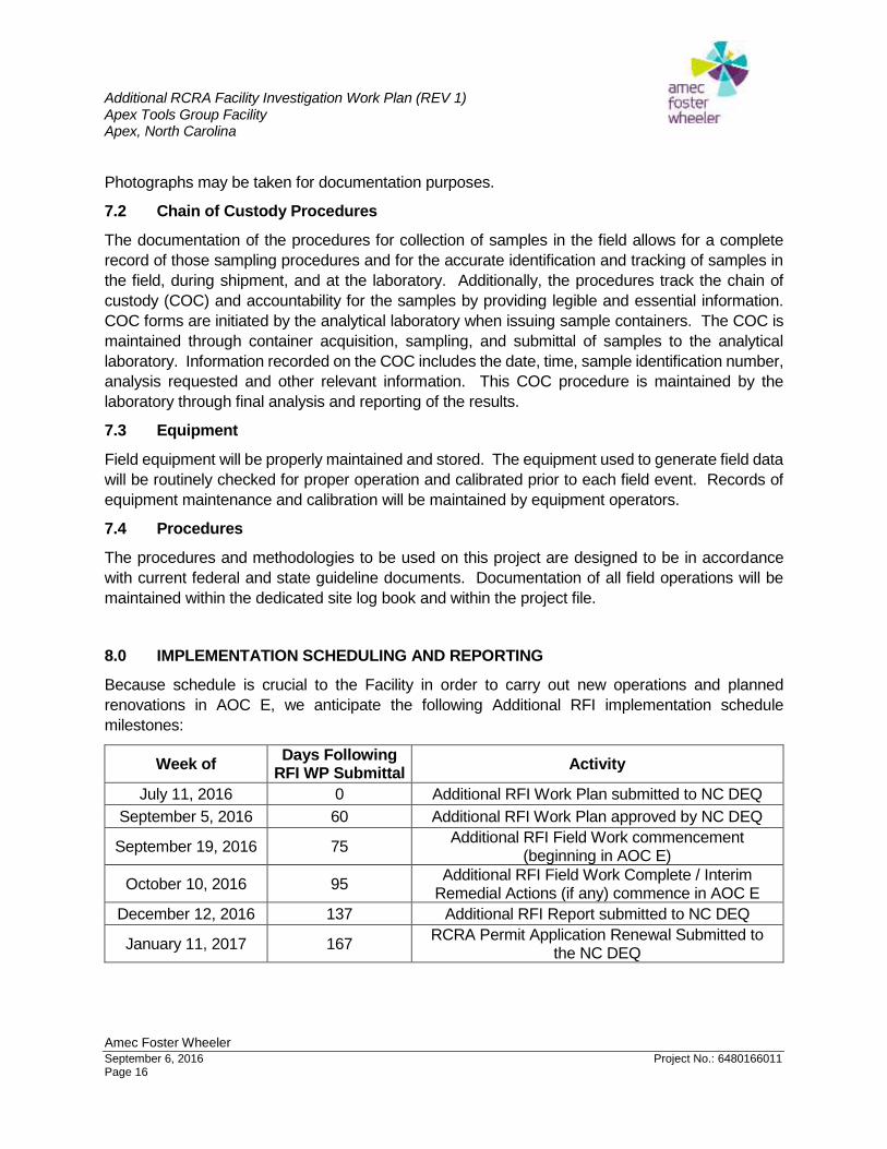
8.0 IMPLEMENTATION SCHEDULING AND REPORTING
Because schedule is crucial to the Facility in order to carry out new operations and planned
renovations in AOC E, we anticipate the following Additional RFI implementation schedule
milestones:
Week of Days Following
RFI WP Submittal Activity
July 11, 2016 0 Additional RFI Work Plan submitted to NC DEQ
September 5, 2016 60 Additional RFI Work Plan approved by NC DEQ
September 19, 2016 75 Additional RFI Field Work commencement
(beginning in AOC E)
October 10, 2016 95 Additional RFI Field Work Complete / Interim
Remedial Actions (if any) commence in AOC E
December 12, 2016 137 Additional RFI Report submitted to NC DEQ
January 11, 2017 167 RCRA Permit Application Renewal Submitted to
the NC DEQ
Additional RCRA Facility Investigation Work Plan (REV 1) Apex Tools Group Facility Apex, North Carolina
Amec Foster Wheeler
September 6, 2016 Project No.: 6480166011 Page 17
Following completion of the Additional RFI (within four to six weeks of receipt of analytical data),
Amec Foster Wheeler will prepare an Additional RFI Report. The Report will include details of work
conducted, analytical results, comparison to applicable regulatory standards, and conclusions/
recommendations. Summary tables and results maps will be included as part of the Report.
Additionally, as is required by the Facility’s RCRA Permit, an updated RCRA Part B Permit
Application Renewal will be submitted to the NC DEQ documenting investigations completed,
remedial activities performed and status of SWMUs/AOCs by January 11, 2017.
9.0 HEALTH AND SAFETY
Remedial activities at the Site will be conducted in accordance with a project specific Health and
Safety Plan (HASP). The HASP is provided with this Additional RFI WP as Appendix A. The
HASP addresses the specific health and safety issues associated with drilling, soil sampling, and
groundwater sampling.
10.0 SUMMARY AND LIMITATIONS
This Additional RFI WP provides a technical approach for investigating SWMUs, AOCs and AOIs
at the ATG Facility located in Apex, North Carolina. This Additional RFI WP has been developed
in accordance with generally accepted environmental practices and the requirements of the
Facility’s RCRA permit. Historical RFI activities presented in this Additional RFI WP have been
prepared by Amec Foster Wheeler from information provided by the Facility.
11.0 REFERENCES
Addendum to RCRA Facility Investigation, Westinghouse Environmental and Geotechnical
Services, Inc., October 1991.
ASTM D5092-04(2010)e1, Standard Practice for Design and Installation of Groundwater Monitoring
Wells, ASTM International, West Conshohocken, PA, 2010.
North Carolina Department of Natural Resources and Community Development (DNRCD),
Geologic Map of North Carolina, Scale 1:500,000, 1985.
North Carolina Department of Environmental Quality (NC DEQ), Inactive Hazardous Site Branch
(IHSB), Guidelines for Assessment and Cleanup, October 2015.
North Carolina Department of Environmental and Natural Resources (NCDENR) Administrative
Code Title 15A, Subchapter 2C Section .0100 Well Construction Standards. Current
through October 1, 2009.
NCDENR, Guidance for the Determination and Comparison of Background of Naturally Occurring
Constituents in Soil. January 2006.NCDENR, Hazardous Waste Management Permit,
Issuance of Final Permit, EPA ID NCD 042 892 067, July 20, 2007.
Additional RCRA Facility Investigation Work Plan (REV 1) Apex Tools Group Facility Apex, North Carolina
Amec Foster Wheeler
September 6, 2016 Project No.: 6480166011 Page 18
Monitoring Well Installation and Hydrogeologic Investigation, Soil & Material Engineers, Inc.,
October 1981.
North Carolina Department of Environment and Natural Resources (NCDENR) Division of Waste
Management, Copper Hand Tools Apex Operation, Hazardous Waste Management Permit,
EPA ID: NCD042892067, July 20, 2007.
RCRA Facility Investigation, Westinghouse Environmental and Geotechnical Services, Inc., July
1990.
U.S. EPA, Handbook of Suggested Practices for the Design and Installation of Ground-Water
Monitoring Wells, March 1991.
U.S. EPA, Region 1, Low Stress (Low Flow) Purging and Sampling Procedure for the Collection of
Groundwater Samples from Monitoring Wells – EQASOP-GW 001, Revised January 19,
2010.
U.S. EPA, Region 4, Soil Sampling – SESDPROC-300-R3, Effective Date August 21, 2014.
U.S. EPA, Region 4, Management of Investigation Derived Waste – SESDPROC-202-R3, Effective
Date July 3, 2014.
U.S. EPA, Statistical Analysis of Groundwater Monitoring Data at RCRA Facilities – Unified
Guidance, March 2009.
U.S. EPA, Waste Management Division, Interim Final RFI Guidance Volume I of IV, Development
of and RFI WP and General Considerations for RCRA Facility Investigations, May, 1989

Additional RCRA Facility Investigation Work Plan (REV 1) Apex Tools Group Facility Apex, North Carolina
FIGURES
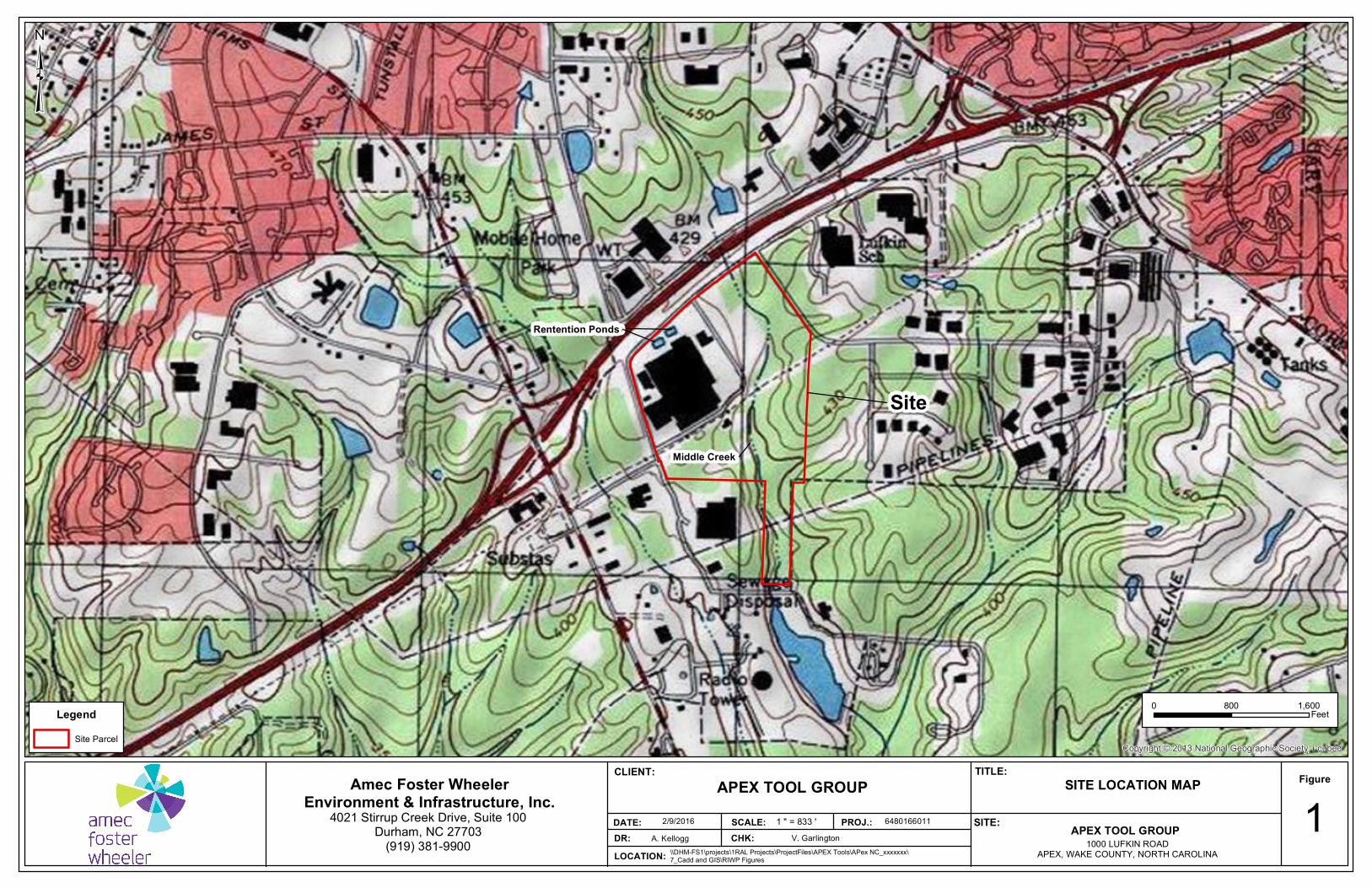
Site
Middle Creek
Rentention PondsRentention Ponds
Copyright:© 2013 National Geographic Society, i-cubed
0 1,600800FeetLegend
Site Parcel
³
APEX TOOL GROUP1000 LUFKIN ROAD
APEX, WAKE COUNTY, NORTH CAROLINA
Figure
DR: CHK:DATE:
SITE LOCATION MAP
1A. Kellogg V. Garlington
2/9/2016
CLIENT:
PROJ.: 6480166011
TITLE:
SCALE: SITE:
Amec Foster WheelerEnvironment & Infrastructure, Inc.
4021 Stirrup Creek Drive, Suite 100Durham, NC 27703
(919) 381-9900LOCATION: \\DHM-FS1\projects\1RAL Projects\ProjectFiles\APEX Tools\APex NC_xxxxxxx\
7_Cadd and GIS\RIWP Figures
APEX TOOL GROUP1 " = 833 '
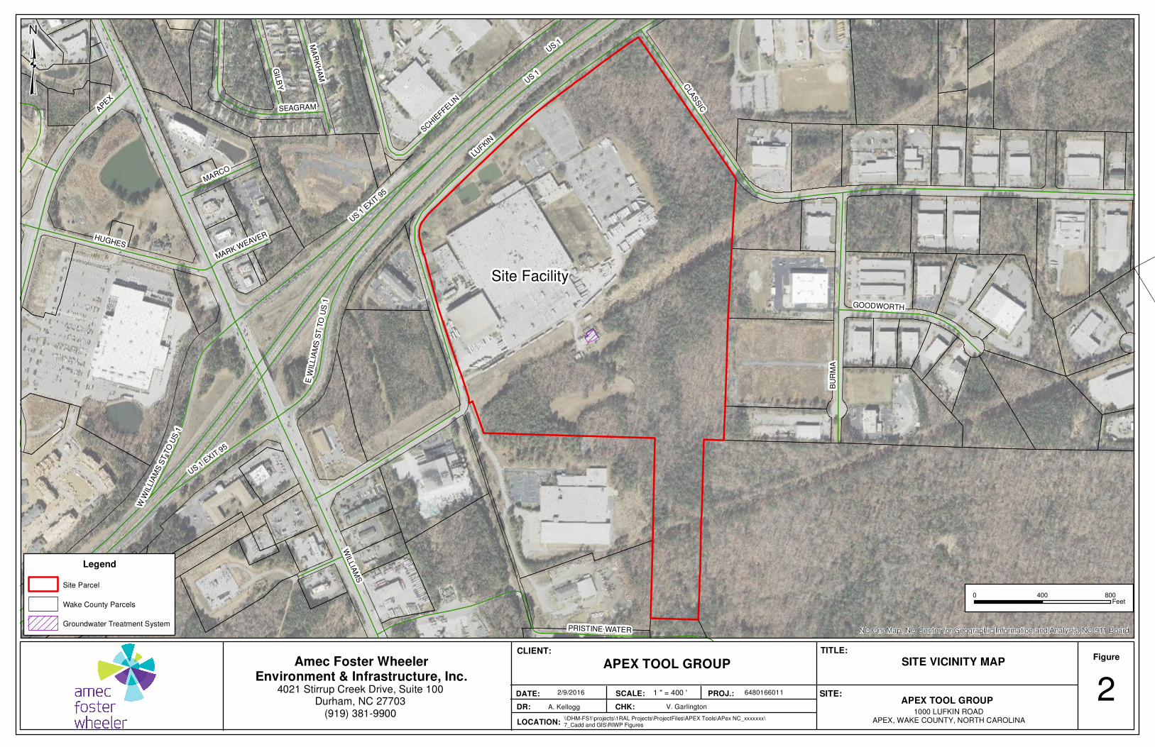
Site Facility
US 1
LUFKIN
WIL
LIA
MS
CLA
SSIC
APE
X
BU
RM
A
HUGHES
US 1 E
XIT 9
5
PRISTINE WATER
SCHIE
FFELI
N
GIL
BY
SEAGRAM
MA
RK
HA
M
GOODWORTH
MARCO
W W
ILLIA
MS
ST T
O U
S 1
E W
ILL
IAM
S S
T T
O U
S 1
MARK WEAVER
US 1
US 1 E
XIT 9
5
NC OneMap, NC Center for Geographic Information and Analysis, NC 911 Board
0 800400Feet
Legend
Site Parcel
Wake County Parcels
Groundwater Treatment System
³
APEX TOOL GROUP1000 LUFKIN ROAD
APEX, WAKE COUNTY, NORTH CAROLINA
Figure
DR: CHK:
DATE:
SITE VICINITY MAP
2A. Kellogg V. Garlington
2/9/2016
CLIENT:
PROJ.: 6480166011
TITLE:
SCALE: SITE:
Amec Foster WheelerEnvironment & Infrastructure, Inc.
4021 Stirrup Creek Drive, Suite 100Durham, NC 27703
(919) 381-9900LOCATION:
\\DHM-FS1\projects\1RAL Projects\ProjectFiles\APEX Tools\APex NC_xxxxxxx\7_Cadd and GIS\RIWP Figures
APEX TOOL GROUP
1 " = 400 '
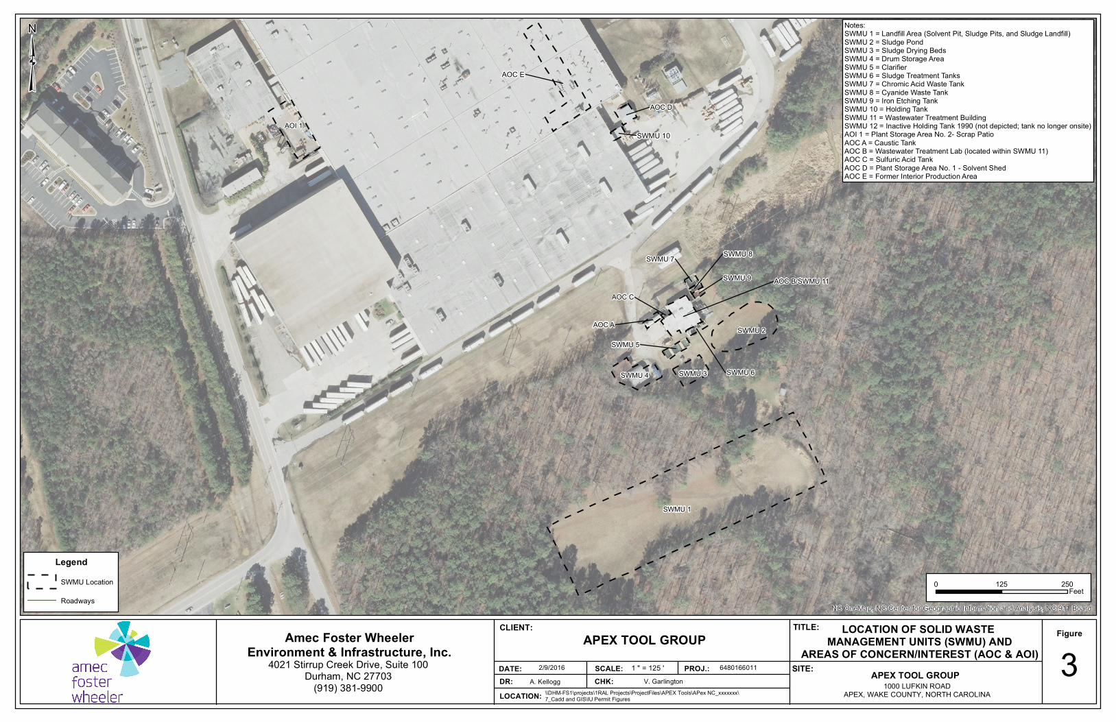
SWMU 8
SWMU 10
AOC E
SWMU 1
SWMU 2
AOI 1
AOC B/SWMU 11
SWMU 4 SWMU 3
AOC D
SWMU 5
SWMU 6
AOC A
SWMU 7
SWMU 9
AOC C
NC OneMap, NC Center for Geographic Information and Analysis, NC 911 Board
0 250125Feet
LegendSWMU Location
Roadways
³
APEX TOOL GROUP1000 LUFKIN ROAD
APEX, WAKE COUNTY, NORTH CAROLINA
Figure
DR: CHK:DATE:
LOCATION OF SOLID WASTE MANAGEMENT UNITS (SWMU) AND
AREAS OF CONCERN/INTEREST (AOC & AOI) 3A. Kellogg V. Garlington
2/9/2016
CLIENT:
PROJ.: 6480166011
TITLE:
SCALE: SITE:
Amec Foster WheelerEnvironment & Infrastructure, Inc.
4021 Stirrup Creek Drive, Suite 100Durham, NC 27703
(919) 381-9900LOCATION: \\DHM-FS1\projects\1RAL Projects\ProjectFiles\APEX Tools\APex NC_xxxxxxx\
7_Cadd and GIS\IU Permit Figures
APEX TOOL GROUP1 " = 125 '
Notes:SWMU 1 = Landfill Area (Solvent Pit, Sludge Pits, and Sludge Landfill)SWMU 2 = Sludge PondSWMU 3 = Sludge Drying BedsSWMU 4 = Drum Storage AreaSWMU 5 = ClarifierSWMU 6 = Sludge Treatment TanksSWMU 7 = Chromic Acid Waste TankSWMU 8 = Cyanide Waste TankSWMU 9 = Iron Etching TankSWMU 10 = Holding TankSWMU 11 = Wastewater Treatment BuildingSWMU 12 = Inactive Holding Tank 1990 (not depicted; tank no longer onsite)AOI 1 = Plant Storage Area No. 2- Scrap PatioAOC A = Caustic TankAOC B = Wastewater Treatment Lab (located within SWMU 11)AOC C = Sulfuric Acid TankAOC D = Plant Storage Area No. 1 - Solvent ShedAOC E = Former Interior Production Area
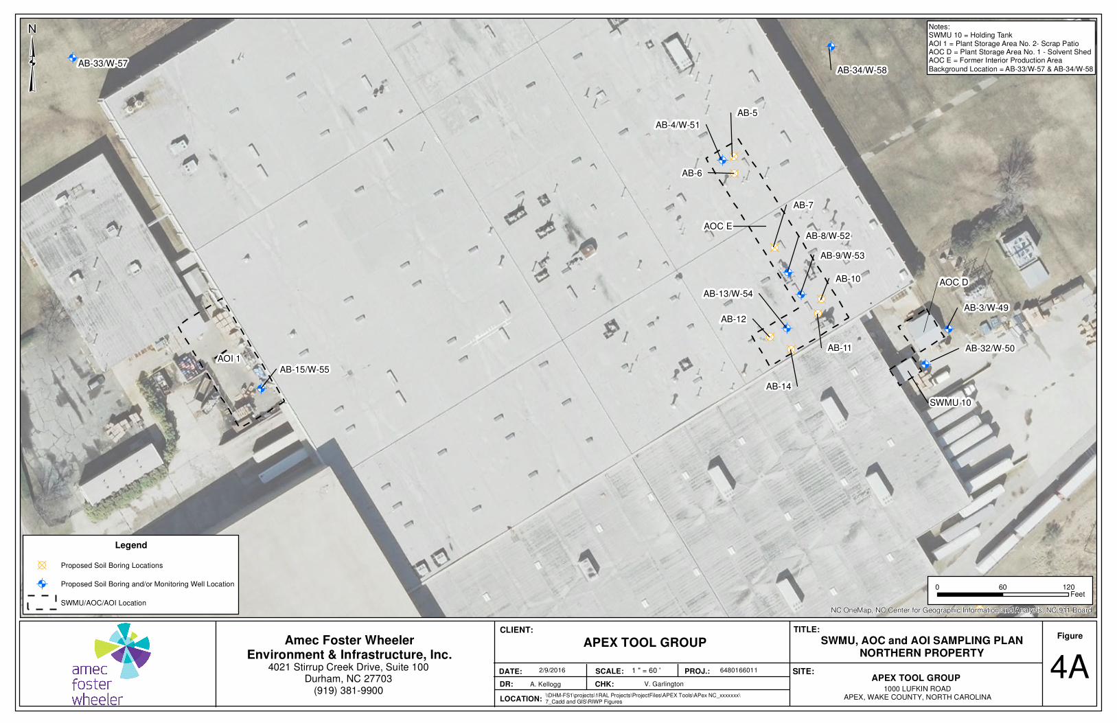
Ò!(
Ò!(
Ò!(
Ò!(
Ò!(
Ò!(
Ò!(
Ò!(
Ò!(
!B!B
!B!B
!B
!B
!B
!B
!B
!B
!B
!B
SWMU 10
AOC E
AB-4/W-51
AB-5
AB-6
AB-7
AB-10
AB-11
AB-14
AB-12
AB-13/W-54
AB-8/W-52
AB-9/W-53
AB-33/W-57AB-34/W-58
AOI 1
AOC D
AB-15/W-55
AB-32/W-50
AB-3/W-49
NC OneMap, NC Center for Geographic Information and Analysis, NC 911 Board
0 12060Feet
Legend
!B Proposed Soil Boring Locations
Ò!( Proposed Soil Boring and/or Monitoring Well Location
SWMU/AOC/AOI Location
³
APEX TOOL GROUP1000 LUFKIN ROAD
APEX, WAKE COUNTY, NORTH CAROLINA
Figure
DR: CHK:
DATE:
SWMU, AOC and AOI SAMPLING PLANNORTHERN PROPERTY
4AA. Kellogg V. Garlington
2/9/2016
CLIENT:
PROJ.: 6480166011
TITLE:
SCALE: SITE:
Amec Foster WheelerEnvironment & Infrastructure, Inc.
4021 Stirrup Creek Drive, Suite 100Durham, NC 27703
(919) 381-9900LOCATION:
\\DHM-FS1\projects\1RAL Projects\ProjectFiles\APEX Tools\APex NC_xxxxxxx\7_Cadd and GIS\RIWP Figures
APEX TOOL GROUP
1 " = 60 '
Notes:SWMU 10 = Holding TankAOI 1 = Plant Storage Area No. 2- Scrap PatioAOC D = Plant Storage Area No. 1 - Solvent ShedAOC E = Former Interior Production Area
Background Location = AB-33/W-57 & AB-34/W-58
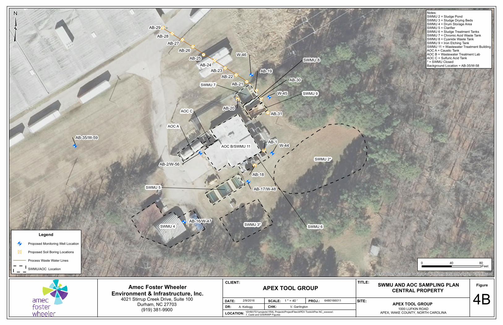
!B
!B
!B
!B
!B
!B
!B
!B!B
!B
!B
!B!B
!B
!B
!B
!B
!B
!B
!B
!B
!B
!B
!B
Ò!(Ò!(
Ò!(
Ò!(
Ò!(
Ò!(
Ò!(
Ò!(
Ò!(
Ò!(
Ò!(
Ò!(
Ò!(
Ò!(
Ò!(
Ò!(
Ò!(
Ò!(
Ò!(
Ò!(
Ò!(
Ò!(
Ò!(
SWMU 8
AB-30AB-19
W-45
AB-18
AB-16/W-47
AB-35/W-59
SWMU 2*
AOC B/SWMU 11
SWMU 4 SWMU 3*
SWMU 5
SWMU 6
AOC A
SWMU 7SWMU 9
AOC C
AB-17/W-48
W-46
AB-2/W-56
W-44
AB-22AB-23
AB-24AB-25
AB-26AB-27
AB-21
AB-20
AB-1
AB-28AB-29
AB-31
NC OneMap, NC Center for Geographic Information and Analysis, NC 911 Board
0 8040Feet
Legend
Ò!( Proposed Monitoring Well Location
!B Proposed Soil Boring Locations
Process Waste Water Lines
SWMU/AOC Location
³
APEX TOOL GROUP1000 LUFKIN ROAD
APEX, WAKE COUNTY, NORTH CAROLINA
Figure
DR: CHK:DATE:
SWMU AND AOC SAMPLING PLANCENTRAL PROPERTY 4B
A. Kellogg V. Garlington2/9/2016
CLIENT:
PROJ.: 6480166011
TITLE:
SCALE: SITE:
Amec Foster WheelerEnvironment & Infrastructure, Inc.
4021 Stirrup Creek Drive, Suite 100Durham, NC 27703
(919) 381-9900LOCATION: \\DHM-FS1\projects\1RAL Projects\ProjectFiles\APEX Tools\APex NC_xxxxxxx\
7_Cadd and GIS\RIWP Figures
APEX TOOL GROUP1 " = 40 '
Notes:SWMU 2 = Sludge PondSWMU 3 = Sludge Drying BedsSWMU 4 = Drum Storage AreaSWMU 5 = ClarifierSWMU 6 = Sludge Treatment TanksSWMU 7 = Chromic Acid Waste TankSWMU 8 = Cyanide Waste TankSWMU 9 = Iron Etching TankSWMU 11 = Wastewater Treatment BuildingAOC A = Caustic TankAOC B = Wastewater Treatment LabAOC C = Sulfuric Acid Tank* = SWMU ClosedBackground Location = AB-35/W-58
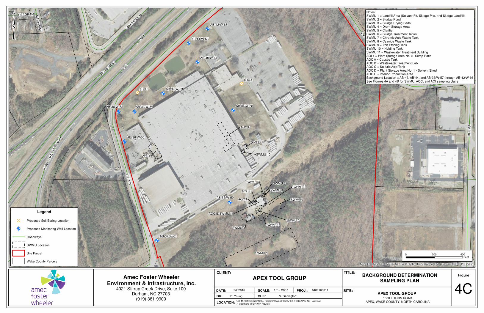
Ò!( Ò!(
Ò!(
Ò!(
Ò!(
Ò!(
Ò!(
Ò!(
Ò!(
Ò!(
!B
!B
AB-42/W-66
AB-41/W-65
AB-40/W-64
AB-39/W-63
AB-38/W-62
AB-37/W-61
AB-36/W-60
AB-35/W-59
AB-34/W-58AB-33/W-57
AB-44
AB-43
SWMU 1
AOC E
AOI 1
SWMU 2
SWMU 4SWMU 3
AOC B/SWMU 11
AOC D
SWMU 5
AOC A
SWMU 6
SWMU 7
SWMU 10
SWMU 9
SWMU 8
AOC C
US 1
LU
FK
IN
BU
RM
A
CLA
SSIC
US 1
EXIT
95
E W
ILLIA
MS
ST T
O U
S 1
SCHIE
FFELI
NSEAGRAM MA
RK
HA
M
US 1
NC OneMap, NC Center for Geographic Information and Analysis, NC 911 Board
0 400200Feet
Legend
!B Proposed Soil Boring Location
Ò!( Proposed Monitoring Well Location
Roadways
SWMU Location
Site Parcel
Wake County Parcels
³
APEX TOOL GROUP1000 LUFKIN ROAD
APEX, WAKE COUNTY, NORTH CAROLINA
Figure
DR: CHK:
DATE:
BACKGROUND DETERMINATIONSAMPLING PLAN
4CD. Young V. Garlington
9/2/2016
CLIENT:
PROJ.: 6480166011
TITLE:
SCALE: SITE:
Amec Foster WheelerEnvironment & Infrastructure, Inc.
4021 Stirrup Creek Drive, Suite 100Durham, NC 27703
(919) 381-9900LOCATION:
\\DHM-FS1\projects\1RAL Projects\ProjectFiles\APEX Tools\APex NC_xxxxxxx\7_Cadd and GIS\RIWP Figures
APEX TOOL GROUP
1 " = 200 '
Notes:SWMU 1 = Landfill Area (Solvent Pit, Sludge Pits, and Sludge Landfill)SWMU 2 = Sludge PondSWMU 3 = Sludge Drying BedsSWMU 4 = Drum Storage Area
SWMU 5 = ClarifierSWMU 6 = Sludge Treatment TanksSWMU 7 = Chromic Acid Waste TankSWMU 8 = Cyanide Waste TankSWMU 9 = Iron Etching TankSWMU 10 = Holding TankSWMU 11 = Wastewater Treatment BuildingAOI 1 = Plant Storage Area No. 2- Scrap PatioAOC A = Caustic TankAOC B = Wastewater Treatment LabAOC C = Sulfuric Acid TankAOC D = Plant Storage Area No. 1 - Solvent ShedAOC E = Interior Production AreaBackground Location = AB-43, AB-44, and AB-33/W-57 through AB-42/W-66See Figures 4A and 4B for SWMU, AOC, and AOI sampling plans

Additional RCRA Facility Investigation Work Plan (REV 1) Apex Tools Group Facility Apex, North Carolina
TABLES
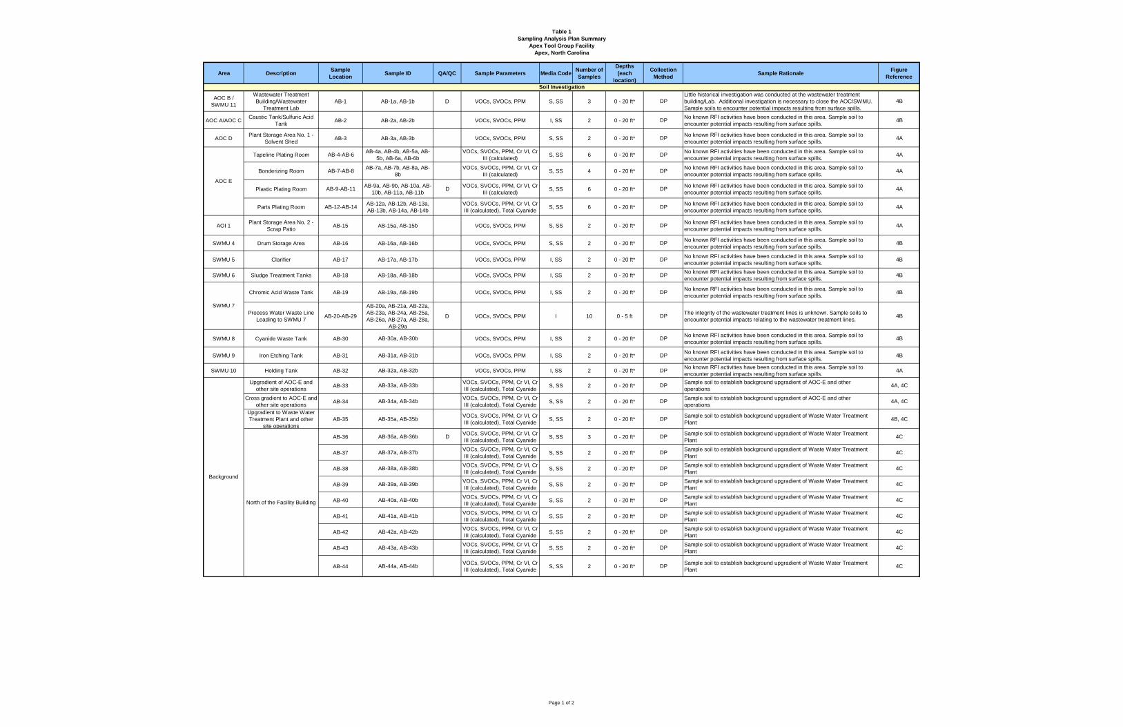
Table 1
Sampling Analysis Plan Summary
Apex Tool Group Facility
Apex, North Carolina
Area DescriptionSample
LocationSample ID QA/QC Sample Parameters Media Code
Number of
Samples
Depths
(each
location)
Collection
MethodSample Rationale
Figure
Reference
AOC B /
SWMU 11
Wastewater Treatment
Building/Wastewater
Treatment Lab
AB-1 AB-1a, AB-1b D VOCs, SVOCs, PPM S, SS 3 0 - 20 ft* DP
Little historical investigation was conducted at the wastewater treatment
building/Lab. Additional investigation is necessary to close the AOC/SWMU.
Sample soils to encounter potential impacts resulting from surface spills.
4B
AOC A/AOC CCaustic Tank/Sulfuric Acid
TankAB-2 AB-2a, AB-2b VOCs, SVOCs, PPM I, SS 2 0 - 20 ft* DP
No known RFI activities have been conducted in this area. Sample soil to
encounter potential impacts resulting from surface spills.4B
AOC DPlant Storage Area No. 1 -
Solvent ShedAB-3 AB-3a, AB-3b VOCs, SVOCs, PPM S, SS 2 0 - 20 ft* DP
No known RFI activities have been conducted in this area. Sample soil to
encounter potential impacts resulting from surface spills.4A
Tapeline Plating Room AB-4-AB-6AB-4a, AB-4b, AB-5a, AB-
5b, AB-6a, AB-6b
VOCs, SVOCs, PPM, Cr VI, Cr
III (calculated)S, SS 6 0 - 20 ft* DP
No known RFI activities have been conducted in this area. Sample soil to
encounter potential impacts resulting from surface spills.4A
Bonderizing Room AB-7-AB-8AB-7a, AB-7b, AB-8a, AB-
8b
VOCs, SVOCs, PPM, Cr VI, Cr
III (calculated)S, SS 4 0 - 20 ft* DP
No known RFI activities have been conducted in this area. Sample soil to
encounter potential impacts resulting from surface spills.4A
Plastic Plating Room AB-9-AB-11AB-9a, AB-9b, AB-10a, AB-
10b, AB-11a, AB-11bD
VOCs, SVOCs, PPM, Cr VI, Cr
III (calculated)S, SS 6 0 - 20 ft* DP
No known RFI activities have been conducted in this area. Sample soil to
encounter potential impacts resulting from surface spills.4A
Parts Plating Room AB-12-AB-14AB-12a, AB-12b, AB-13a,
AB-13b, AB-14a, AB-14b
VOCs, SVOCs, PPM, Cr VI, Cr
III (calculated), Total CyanideS, SS 6 0 - 20 ft* DP
No known RFI activities have been conducted in this area. Sample soil to
encounter potential impacts resulting from surface spills.4A
AOI 1Plant Storage Area No. 2 -
Scrap PatioAB-15 AB-15a, AB-15b VOCs, SVOCs, PPM S, SS 2 0 - 20 ft* DP
No known RFI activities have been conducted in this area. Sample soil to
encounter potential impacts resulting from surface spills.4A
SWMU 4 Drum Storage Area AB-16 AB-16a, AB-16b VOCs, SVOCs, PPM S, SS 2 0 - 20 ft* DPNo known RFI activities have been conducted in this area. Sample soil to
encounter potential impacts resulting from surface spills.4B
SWMU 5 Clarifier AB-17 AB-17a, AB-17b VOCs, SVOCs, PPM I, SS 2 0 - 20 ft* DPNo known RFI activities have been conducted in this area. Sample soil to
encounter potential impacts resulting from surface spills.4B
SWMU 6 Sludge Treatment Tanks AB-18 AB-18a, AB-18b VOCs, SVOCs, PPM I, SS 2 0 - 20 ft* DPNo known RFI activities have been conducted in this area. Sample soil to
encounter potential impacts resulting from surface spills.4B
Chromic Acid Waste Tank AB-19 AB-19a, AB-19b VOCs, SVOCs, PPM I, SS 2 0 - 20 ft* DPNo known RFI activities have been conducted in this area. Sample soil to
encounter potential impacts resulting from surface spills.4B
Process Water Waste Line
Leading to SWMU 7AB-20-AB-29
AB-20a, AB-21a, AB-22a,
AB-23a, AB-24a, AB-25a,
AB-26a, AB-27a, AB-28a,
AB-29a
D VOCs, SVOCs, PPM I 10 0 - 5 ft DPThe integrity of the wastewater treatment lines is unknown. Sample soils to
encounter potential impacts relating to the wastewater treatment lines. 4B
SWMU 8 Cyanide Waste Tank AB-30 AB-30a, AB-30b VOCs, SVOCs, PPM I, SS 2 0 - 20 ft* DPNo known RFI activities have been conducted in this area. Sample soil to
encounter potential impacts resulting from surface spills.4B
SWMU 9 Iron Etching Tank AB-31 AB-31a, AB-31b VOCs, SVOCs, PPM I, SS 2 0 - 20 ft* DPNo known RFI activities have been conducted in this area. Sample soil to
encounter potential impacts resulting from surface spills.4B
SWMU 10 Holding Tank AB-32 AB-32a, AB-32b VOCs, SVOCs, PPM I, SS 2 0 - 20 ft* DPNo known RFI activities have been conducted in this area. Sample soil to
encounter potential impacts resulting from surface spills.4A
Upgradient of AOC-E and
other site operationsAB-33 AB-33a, AB-33b
VOCs, SVOCs, PPM, Cr VI, Cr
III (calculated), Total CyanideS, SS 2 0 - 20 ft* DP
Sample soil to establish background upgradient of AOC-E and other
operations4A, 4C
Cross gradient to AOC-E and
other site operationsAB-34 AB-34a, AB-34b
VOCs, SVOCs, PPM, Cr VI, Cr
III (calculated), Total CyanideS, SS 2 0 - 20 ft* DP
Sample soil to establish background upgradient of AOC-E and other
operations4A, 4C
Upgradient to Waste Water
Treatment Plant and other
site operations
AB-35 AB-35a, AB-35bVOCs, SVOCs, PPM, Cr VI, Cr
III (calculated), Total CyanideS, SS 2 0 - 20 ft* DP
Sample soil to establish background upgradient of Waste Water Treatment
Plant4B, 4C
AB-36 AB-36a, AB-36b DVOCs, SVOCs, PPM, Cr VI, Cr
III (calculated), Total CyanideS, SS 3 0 - 20 ft* DP
Sample soil to establish background upgradient of Waste Water Treatment
Plant4C
AB-37 AB-37a, AB-37bVOCs, SVOCs, PPM, Cr VI, Cr
III (calculated), Total CyanideS, SS 2 0 - 20 ft* DP
Sample soil to establish background upgradient of Waste Water Treatment
Plant4C
AB-38 AB-38a, AB-38bVOCs, SVOCs, PPM, Cr VI, Cr
III (calculated), Total CyanideS, SS 2 0 - 20 ft* DP
Sample soil to establish background upgradient of Waste Water Treatment
Plant4C
AB-39 AB-39a, AB-39bVOCs, SVOCs, PPM, Cr VI, Cr
III (calculated), Total CyanideS, SS 2 0 - 20 ft* DP
Sample soil to establish background upgradient of Waste Water Treatment
Plant4C
AB-40 AB-40a, AB-40bVOCs, SVOCs, PPM, Cr VI, Cr
III (calculated), Total CyanideS, SS 2 0 - 20 ft* DP
Sample soil to establish background upgradient of Waste Water Treatment
Plant4C
AB-41 AB-41a, AB-41bVOCs, SVOCs, PPM, Cr VI, Cr
III (calculated), Total CyanideS, SS 2 0 - 20 ft* DP
Sample soil to establish background upgradient of Waste Water Treatment
Plant4C
AB-42 AB-42a, AB-42bVOCs, SVOCs, PPM, Cr VI, Cr
III (calculated), Total CyanideS, SS 2 0 - 20 ft* DP
Sample soil to establish background upgradient of Waste Water Treatment
Plant4C
AB-43 AB-43a, AB-43bVOCs, SVOCs, PPM, Cr VI, Cr
III (calculated), Total CyanideS, SS 2 0 - 20 ft* DP
Sample soil to establish background upgradient of Waste Water Treatment
Plant4C
AB-44 AB-44a, AB-44bVOCs, SVOCs, PPM, Cr VI, Cr
III (calculated), Total CyanideS, SS 2 0 - 20 ft* DP
Sample soil to establish background upgradient of Waste Water Treatment
Plant4C
Soil Investigation
SWMU 7
AOC E
Background
North of the Facility Building
Page 1 of 2
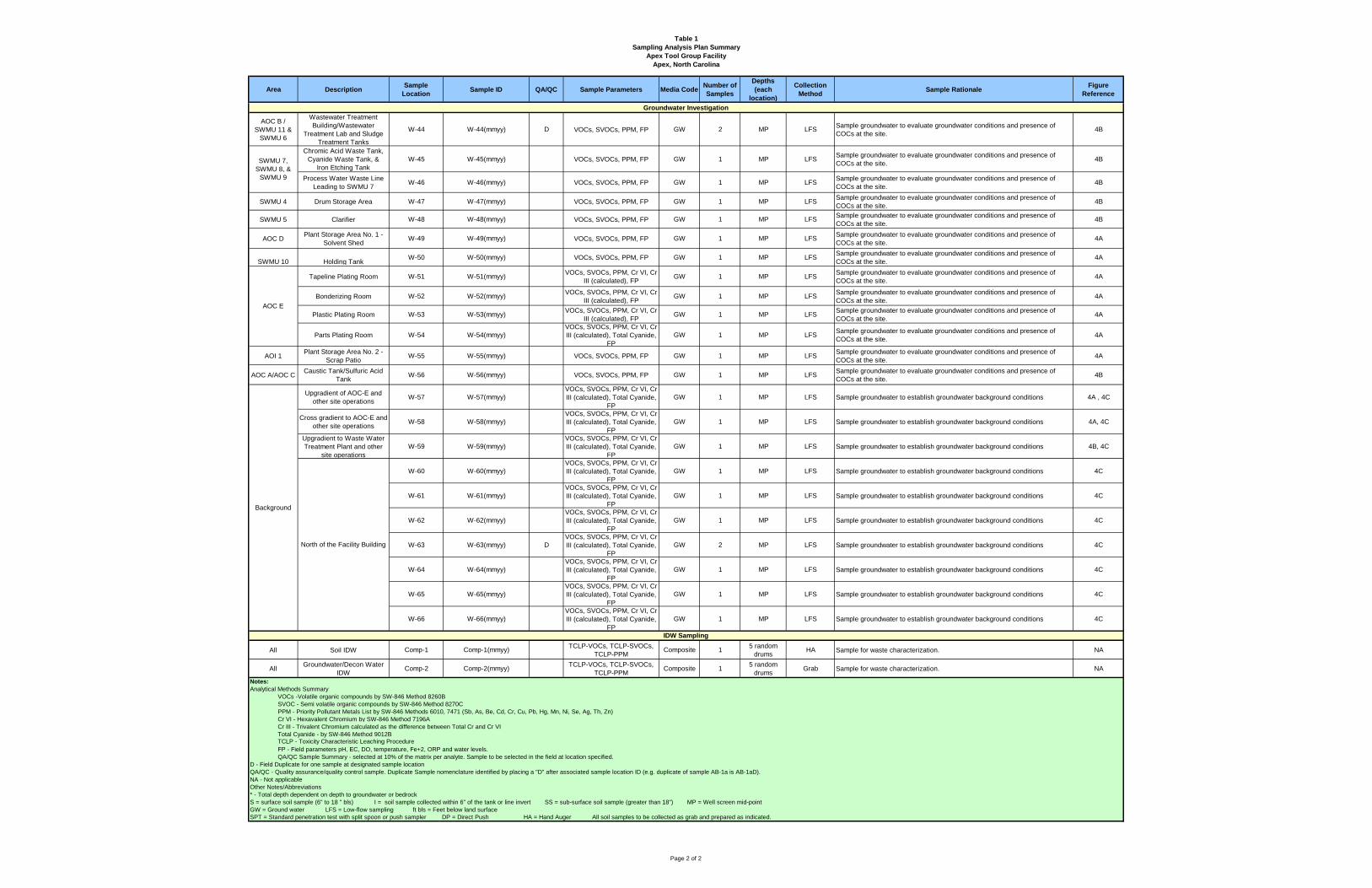
Table 1
Sampling Analysis Plan Summary
Apex Tool Group Facility
Apex, North Carolina
Area DescriptionSample
LocationSample ID QA/QC Sample Parameters Media Code
Number of
Samples
Depths
(each
location)
Collection
MethodSample Rationale
Figure
Reference
Soil Investigation
AOC B /
SWMU 11 &
SWMU 6
Wastewater Treatment
Building/Wastewater
Treatment Lab and Sludge
Treatment Tanks
W-44 W-44(mmyy) D VOCs, SVOCs, PPM, FP GW 2 MP LFSSample groundwater to evaluate groundwater conditions and presence of
COCs at the site. 4B
Chromic Acid Waste Tank,
Cyanide Waste Tank, &
Iron Etching Tank
W-45 W-45(mmyy) VOCs, SVOCs, PPM, FP GW 1 MP LFSSample groundwater to evaluate groundwater conditions and presence of
COCs at the site.4B
Process Water Waste Line
Leading to SWMU 7W-46 W-46(mmyy) VOCs, SVOCs, PPM, FP GW 1 MP LFS
Sample groundwater to evaluate groundwater conditions and presence of
COCs at the site. 4B
SWMU 4 Drum Storage Area W-47 W-47(mmyy) VOCs, SVOCs, PPM, FP GW 1 MP LFSSample groundwater to evaluate groundwater conditions and presence of
COCs at the site.4B
SWMU 5 Clarifier W-48 W-48(mmyy) VOCs, SVOCs, PPM, FP GW 1 MP LFSSample groundwater to evaluate groundwater conditions and presence of
COCs at the site.4B
AOC D Plant Storage Area No. 1 -
Solvent ShedW-49 W-49(mmyy) VOCs, SVOCs, PPM, FP GW 1 MP LFS
Sample groundwater to evaluate groundwater conditions and presence of
COCs at the site.4A
SWMU 10 Holding TankW-50 W-50(mmyy) VOCs, SVOCs, PPM, FP GW 1 MP LFS
Sample groundwater to evaluate groundwater conditions and presence of
COCs at the site.4A
Tapeline Plating Room W-51 W-51(mmyy)VOCs, SVOCs, PPM, Cr VI, Cr
III (calculated), FPGW 1 MP LFS
Sample groundwater to evaluate groundwater conditions and presence of
COCs at the site.4A
Bonderizing Room W-52 W-52(mmyy)VOCs, SVOCs, PPM, Cr VI, Cr
III (calculated), FPGW 1 MP LFS
Sample groundwater to evaluate groundwater conditions and presence of
COCs at the site.4A
Plastic Plating Room W-53 W-53(mmyy)VOCs, SVOCs, PPM, Cr VI, Cr
III (calculated), FPGW 1 MP LFS
Sample groundwater to evaluate groundwater conditions and presence of
COCs at the site.4A
Parts Plating Room W-54 W-54(mmyy)
VOCs, SVOCs, PPM, Cr VI, Cr
III (calculated), Total Cyanide,
FP
GW 1 MP LFSSample groundwater to evaluate groundwater conditions and presence of
COCs at the site.4A
AOI 1Plant Storage Area No. 2 -
Scrap PatioW-55 W-55(mmyy) VOCs, SVOCs, PPM, FP GW 1 MP LFS
Sample groundwater to evaluate groundwater conditions and presence of
COCs at the site.4A
AOC A/AOC CCaustic Tank/Sulfuric Acid
TankW-56 W-56(mmyy) VOCs, SVOCs, PPM, FP GW 1 MP LFS
Sample groundwater to evaluate groundwater conditions and presence of
COCs at the site.4B
Upgradient of AOC-E and
other site operationsW-57 W-57(mmyy)
VOCs, SVOCs, PPM, Cr VI, Cr
III (calculated), Total Cyanide,
FP
GW 1 MP LFS Sample groundwater to establish groundwater background conditions 4A , 4C
Cross gradient to AOC-E and
other site operationsW-58 W-58(mmyy)
VOCs, SVOCs, PPM, Cr VI, Cr
III (calculated), Total Cyanide,
FP
GW 1 MP LFS Sample groundwater to establish groundwater background conditions 4A, 4C
Upgradient to Waste Water
Treatment Plant and other
site operations
W-59 W-59(mmyy)
VOCs, SVOCs, PPM, Cr VI, Cr
III (calculated), Total Cyanide,
FP
GW 1 MP LFS Sample groundwater to establish groundwater background conditions 4B, 4C
W-60 W-60(mmyy)
VOCs, SVOCs, PPM, Cr VI, Cr
III (calculated), Total Cyanide,
FP
GW 1 MP LFS Sample groundwater to establish groundwater background conditions 4C
W-61 W-61(mmyy)
VOCs, SVOCs, PPM, Cr VI, Cr
III (calculated), Total Cyanide,
FP
GW 1 MP LFS Sample groundwater to establish groundwater background conditions 4C
W-62 W-62(mmyy)
VOCs, SVOCs, PPM, Cr VI, Cr
III (calculated), Total Cyanide,
FP
GW 1 MP LFS Sample groundwater to establish groundwater background conditions 4C
W-63 W-63(mmyy) D
VOCs, SVOCs, PPM, Cr VI, Cr
III (calculated), Total Cyanide,
FP
GW 2 MP LFS Sample groundwater to establish groundwater background conditions 4C
W-64 W-64(mmyy)
VOCs, SVOCs, PPM, Cr VI, Cr
III (calculated), Total Cyanide,
FP
GW 1 MP LFS Sample groundwater to establish groundwater background conditions 4C
W-65 W-65(mmyy)
VOCs, SVOCs, PPM, Cr VI, Cr
III (calculated), Total Cyanide,
FP
GW 1 MP LFS Sample groundwater to establish groundwater background conditions 4C
W-66 W-66(mmyy)
VOCs, SVOCs, PPM, Cr VI, Cr
III (calculated), Total Cyanide,
FP
GW 1 MP LFS Sample groundwater to establish groundwater background conditions 4C
All Soil IDW Comp-1 Comp-1(mmyy)TCLP-VOCs, TCLP-SVOCs,
TCLP-PPMComposite 1
5 random
drumsHA Sample for waste characterization. NA
AllGroundwater/Decon Water
IDWComp-2 Comp-2(mmyy)
TCLP-VOCs, TCLP-SVOCs,
TCLP-PPMComposite 1
5 random
drumsGrab Sample for waste characterization. NA
Notes:
Analytical Methods Summary
VOCs -Volatile organic compounds by SW-846 Method 8260B
SVOC - Semi volatile organic compounds by SW-846 Method 8270C
PPM - Priority Pollutant Metals List by SW-846 Methods 6010, 7471 (Sb, As, Be, Cd, Cr, Cu, Pb, Hg, Mn, Ni, Se, Ag, Th, Zn)
Cr VI - Hexavalent Chromium by SW-846 Method 7196A
Cr III - Trivalent Chromium calculated as the difference between Total Cr and Cr VI
Total Cyanide - by SW-846 Method 9012B
FP - Field parameters pH, EC, DO, temperature, Fe+2, ORP and water levels.
QA/QC Sample Summary - selected at 10% of the matrix per analyte. Sample to be selected in the field at location specified.
D - Field Duplicate for one sample at designated sample location
QA/QC - Quality assurance/quality control sample. Duplicate Sample nomenclature identified by placing a "D" after associated sample location ID (e.g. duplicate of sample AB-1a is AB-1aD).
NA - Not applicable
Other Notes/Abbreviations
* - Total depth dependent on depth to groundwater or bedrock
S = surface soil sample (6" to 18 " bls) I = soil sample collected within 6" of the tank or line invert SS = sub-surface soil sample (greater than 18") MP = Well screen mid-point
GW = Ground water LFS = Low-flow sampling ft bls = Feet below land surface
SPT = Standard penetration test with split spoon or push sampler DP = Direct Push HA = Hand Auger All soil samples to be collected as grab and prepared as indicated.
Groundwater Investigation
TCLP - Toxicity Characteristic Leaching Procedure
SWMU 7,
SWMU 8, &
SWMU 9
AOC E
IDW Sampling
Background
North of the Facility Building
Page 2 of 2
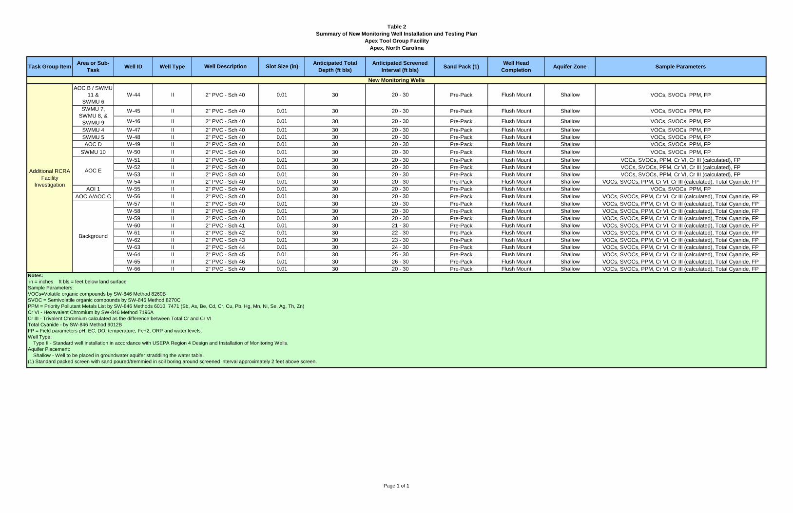
Table 2
Summary of New Monitoring Well Installation and Testing Plan
Apex Tool Group Facility
Apex, North Carolina
AOC B / SWMU
11 &
SWMU 6
W-44 II 2" PVC - Sch 40 0.01 30 20 - 30 Pre-Pack Flush Mount Shallow VOCs, SVOCs, PPM, FP
W-45 II 2" PVC - Sch 40 0.01 30 20 - 30 Pre-Pack Flush Mount Shallow VOCs, SVOCs, PPM, FP
W-46 II 2" PVC - Sch 40 0.01 30 20 - 30 Pre-Pack Flush Mount Shallow VOCs, SVOCs, PPM, FP
SWMU 4 W-47 II 2" PVC - Sch 40 0.01 30 20 - 30 Pre-Pack Flush Mount Shallow VOCs, SVOCs, PPM, FP
SWMU 5 W-48 II 2" PVC - Sch 40 0.01 30 20 - 30 Pre-Pack Flush Mount Shallow VOCs, SVOCs, PPM, FP
AOC D W-49 II 2" PVC - Sch 40 0.01 30 20 - 30 Pre-Pack Flush Mount Shallow VOCs, SVOCs, PPM, FP
SWMU 10 W-50 II 2" PVC - Sch 40 0.01 30 20 - 30 Pre-Pack Flush Mount Shallow VOCs, SVOCs, PPM, FP
W-51 II 2" PVC - Sch 40 0.01 30 20 - 30 Pre-Pack Flush Mount Shallow VOCs, SVOCs, PPM, Cr VI, Cr III (calculated), FP
W-52 II 2" PVC - Sch 40 0.01 30 20 - 30 Pre-Pack Flush Mount Shallow VOCs, SVOCs, PPM, Cr VI, Cr III (calculated), FP
W-53 II 2" PVC - Sch 40 0.01 30 20 - 30 Pre-Pack Flush Mount Shallow VOCs, SVOCs, PPM, Cr VI, Cr III (calculated), FP
W-54 II 2" PVC - Sch 40 0.01 30 20 - 30 Pre-Pack Flush Mount Shallow VOCs, SVOCs, PPM, Cr VI, Cr III (calculated), Total Cyanide, FP
AOI 1 W-55 II 2" PVC - Sch 40 0.01 30 20 - 30 Pre-Pack Flush Mount Shallow VOCs, SVOCs, PPM, FP
AOC A/AOC C W-56 II 2" PVC - Sch 40 0.01 30 20 - 30 Pre-Pack Flush Mount Shallow VOCs, SVOCs, PPM, Cr VI, Cr III (calculated), Total Cyanide, FP
W-57 II 2" PVC - Sch 40 0.01 30 20 - 30 Pre-Pack Flush Mount Shallow VOCs, SVOCs, PPM, Cr VI, Cr III (calculated), Total Cyanide, FP
W-58 II 2" PVC - Sch 40 0.01 30 20 - 30 Pre-Pack Flush Mount Shallow VOCs, SVOCs, PPM, Cr VI, Cr III (calculated), Total Cyanide, FP
W-59 II 2" PVC - Sch 40 0.01 30 20 - 30 Pre-Pack Flush Mount Shallow VOCs, SVOCs, PPM, Cr VI, Cr III (calculated), Total Cyanide, FP
W-60 II 2" PVC - Sch 41 0.01 30 21 - 30 Pre-Pack Flush Mount Shallow VOCs, SVOCs, PPM, Cr VI, Cr III (calculated), Total Cyanide, FP
W-61 II 2" PVC - Sch 42 0.01 30 22 - 30 Pre-Pack Flush Mount Shallow VOCs, SVOCs, PPM, Cr VI, Cr III (calculated), Total Cyanide, FP
W-62 II 2" PVC - Sch 43 0.01 30 23 - 30 Pre-Pack Flush Mount Shallow VOCs, SVOCs, PPM, Cr VI, Cr III (calculated), Total Cyanide, FP
W-63 II 2" PVC - Sch 44 0.01 30 24 - 30 Pre-Pack Flush Mount Shallow VOCs, SVOCs, PPM, Cr VI, Cr III (calculated), Total Cyanide, FP
W-64 II 2" PVC - Sch 45 0.01 30 25 - 30 Pre-Pack Flush Mount Shallow VOCs, SVOCs, PPM, Cr VI, Cr III (calculated), Total Cyanide, FP
W-65 II 2" PVC - Sch 46 0.01 30 26 - 30 Pre-Pack Flush Mount Shallow VOCs, SVOCs, PPM, Cr VI, Cr III (calculated), Total Cyanide, FP
W-66 II 2" PVC - Sch 40 0.01 30 20 - 30 Pre-Pack Flush Mount Shallow VOCs, SVOCs, PPM, Cr VI, Cr III (calculated), Total Cyanide, FPNotes:
in = inches ft bls = feet below land surface
Sample Parameters:
VOCs=Volatile organic compounds by SW-846 Method 8260B
SVOC = Semivolatile organic compounds by SW-846 Method 8270C
PPM = Priority Pollutant Metals List by SW-846 Methods 6010, 7471 (Sb, As, Be, Cd, Cr, Cu, Pb, Hg, Mn, Ni, Se, Ag, Th, Zn)
Cr VI - Hexavalent Chromium by SW-846 Method 7196A
Cr III - Trivalent Chromium calculated as the difference between Total Cr and Cr VI
Total Cyanide - by SW-846 Method 9012B
FP = Field parameters pH, EC, DO, temperature, Fe+2, ORP and water levels.
Well Type:
Type II - Standard well installation in accordance with USEPA Region 4 Design and Installation of Monitoring Wells.
Aquifer Placement:
Shallow - Well to be placed in groundwater aquifer straddling the water table.
(1) Standard packed screen with sand poured/tremmied in soil boring around screened interval approximately 2 feet above screen.
SWMU 7,
SWMU 8, &
SWMU 9
AOC E
Background
Additional RCRA
Facility
Investigation
Task Group Item
New Monitoring Wells
Sample ParametersSand Pack (1)Well Head
CompletionAquifer Zone
Area or Sub-
TaskWell ID
Anticipated Screened
Interval (ft bls)Slot Size (in)
Anticipated Total
Depth (ft bls)Well Type Well Description
Page 1 of 1

Additional RCRA Facility Investigation Work Plan (REV 1) Apex Tools Group Facility Apex, North Carolina
APPENDIX A
Health & Safety Plan
APPENDIX A
SITE-SPECIFIC HEALTH AND SAFETY PLAN
FOR
APEX TOOL GROUP FACILITY
1000 LUFKIN ROAD
APEX, NORTH CAROLINA 27539
Prepared for:
APEX TOOL GROUP, LLC
1000 Lufkin Road
Apex, North Carolina 27539
Prepared by:
Amec Foster Wheeler Environment & Infrastructure, Inc.
4021 Stirrup Creek Drive, Suite 100
Durham, North Carolina 27703
Amec Foster Wheeler Project No. 6480166011
September 2016

Site Specific Health & Safety Plan Apex Tool Group Facility 1000 Lufkin Road Apex, North Carolina 27539 Page ii
SIGNATURE PAGE
Name Signature Date Company
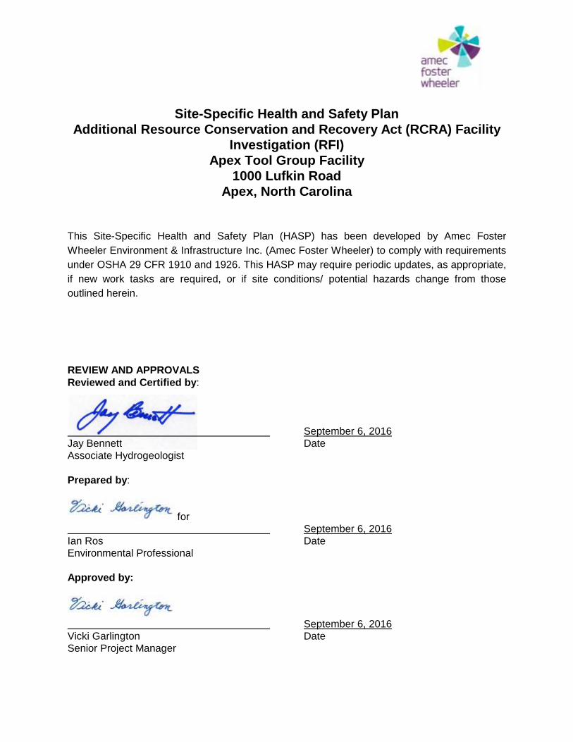
Site-Specific Health and Safety Plan
Additional Resource Conservation and Recovery Act (RCRA) Facility
Investigation (RFI)
Apex Tool Group Facility
1000 Lufkin Road
Apex, North Carolina
This Site-Specific Health and Safety Plan (HASP) has been developed by Amec Foster
Wheeler Environment & Infrastructure Inc. (Amec Foster Wheeler) to comply with requirements
under OSHA 29 CFR 1910 and 1926. This HASP may require periodic updates, as appropriate,
if new work tasks are required, or if site conditions/ potential hazards change from those
outlined herein.
REVIEW AND APPROVALS
Reviewed and Certified by:
September 6, 2016
Jay Bennett Date
Associate Hydrogeologist
Prepared by:
for
September 6, 2016
Ian Ros Date
Environmental Professional
Approved by:
September 6, 2016
Vicki Garlington Date
Senior Project Manager
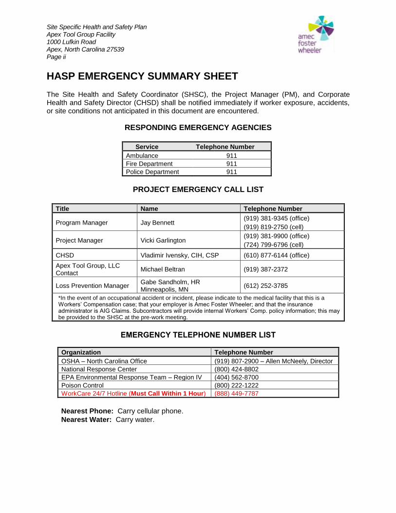
Site Specific Health and Safety Plan Apex Tool Group Facility 1000 Lufkin Road Apex, North Carolina 27539 Page ii
HASP EMERGENCY SUMMARY SHEET The Site Health and Safety Coordinator (SHSC), the Project Manager (PM), and Corporate Health and Safety Director (CHSD) shall be notified immediately if worker exposure, accidents, or site conditions not anticipated in this document are encountered.
RESPONDING EMERGENCY AGENCIES
Service Telephone Number
Ambulance 911
Fire Department 911
Police Department 911
PROJECT EMERGENCY CALL LIST
Title Name Telephone Number
Program Manager Jay Bennett (919) 381-9345 (office)
(919) 819-2750 (cell)
Project Manager Vicki Garlington (919) 381-9900 (office)
(724) 799-6796 (cell)
CHSD Vladimir Ivensky, CIH, CSP (610) 877-6144 (office)
Apex Tool Group, LLC Contact
Michael Beltran (919) 387-2372
Loss Prevention Manager Gabe Sandholm, HR Minneapolis, MN
(612) 252-3785
*In the event of an occupational accident or incident, please indicate to the medical facility that this is a Workers’ Compensation case; that your employer is Amec Foster Wheeler; and that the insurance administrator is AIG Claims. Subcontractors will provide internal Workers’ Comp. policy information; this may be provided to the SHSC at the pre-work meeting.
EMERGENCY TELEPHONE NUMBER LIST
Organization Telephone Number
OSHA – North Carolina Office (919) 807-2900 – Allen McNeely, Director
National Response Center (800) 424-8802
EPA Environmental Response Team – Region IV (404) 562-8700
Poison Control (800) 222-1222
WorkCare 24/7 Hotline (Must Call Within 1 Hour) (888) 449-7787
Nearest Phone: Carry cellular phone.
Nearest Water: Carry water.
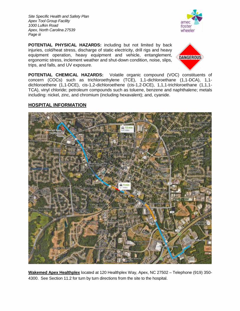
Site Specific Health and Safety Plan Apex Tool Group Facility 1000 Lufkin Road Apex, North Carolina 27539 Page iii
POTENTIAL PHYSICAL HAZARDS: including but not limited by back injuries, cold/heat stress, discharge of static electricity, drill rigs and heavy equipment operation, heavy equipment and vehicle, entanglement, ergonomic stress, inclement weather and shut-down condition, noise, slips, trips, and falls, and UV exposure.
POTENTIAL CHEMICAL HAZARDS: Volatile organic compound (VOC) constituents of concern (COCs) such as trichloroethylene (TCE), 1,1-dichloroethane (1,1-DCA), 1,1-dichloroethene (1,1-DCE), cis-1,2-dichloroethene (cis-1,2-DCE), 1,1,1-trichloroethane (1,1,1-TCA), vinyl chloride; petroleum compounds such as toluene, benzene and naphthalene; metals including: nickel, zinc, and chromium (including hexavalent); and, cyanide.
HOSPITAL INFORMATION
Wakemed Apex Healthplex located at 120 Healthplex Way, Apex, NC 27502 – Telephone (919) 350-
4300. See Section 11.2 for turn by turn directions from the site to the hospital.
Site Specific Health and Safety Plan Apex Tool Group Facility 1000 Lufkin Road Apex, North Carolina 27539 Page iv
IN CASE OF LIFE THREATENING INJURIES, CALL 911
USE AMBULANCE TO CLOSEST TRAUMA CENTER
NOTE: In case of any hazard exposure during and/or prior to medical attention, the
hospital and any emergency response personnel shall be notified that patient and/or the
patient’s clothing may be contaminated.
EMERGENCY CONTACT LIST
IN THE EVENT OF AN ON-SITE EMERGENCY WHILE WORKING ON THIS PROJECT IMMEDIATELY CONTACT THE FOLLOWING IN ORDER:
1. FIRE, POLICE, OR AMBULANCE CALL
911
2. Amec Foster Wheeler PROJECT MANAGERS OR INCIDENT MANAGERS
JAY BENNETT 919-381-9345
Cell 919-819-2750
VICKI GARLINGTON 919-381-1394
Cell 724-799-6796
3. Amec Foster Wheeler ON-SITE ENGINEER AND HEALTH AND SAFETY OFFICERS
IAN ROS 919-381-9907
Cell 252-326-5240
4. APEX TOOL GROUP, LLC
MIKE BELTRAN 919-387-2372
Cell 919-924-6433
5. NORTH CAROLINA EMERGENCY MANAGEMENT (NCDPS)
800-585-0368 6. WAKEMED APEX HEALTHPLEX
919-350-4300
Site Specific Health and Safety Plan Apex Tool Group Facility 1000 Lufkin Road Apex, North Carolina 27539 Page v
TABLE OF CONTENTS
SECTION PAGE
1.0 INTRODUCTION ............................................................................................................ 1
2.0 POTENTIAL SAFETY HAZARDS .................................................................................. 1
2.1 Physical Hazards ...................................................................................................... 1 2.1.1 Drill Rig/GeoProbe/Excavator Safety Inspections ................................................... 1 2.1.2 Safe Operation of Equipment and General Site Conditions .................................... 2 2.1.3 Hazardous Noise .................................................................................................... 2
2.2 Chemical Hazards ..................................................................................................... 3
2.3 Safety Precautions ................................................................................................... 6
3.0 PERSONNEL REQUIREMENTS .................................................................................... 7
3.1 Incident Manager ...................................................................................................... 7
3.2 Site Health and Safety Officer ................................................................................. 7
3.3 Project Personnel ..................................................................................................... 8
4.0 DESIGNATION OF THE LEVELS OF PROTECTION .................................................... 9
4.1 Level D Personal Protection Equipment ................................................................. 9
4.2 Modified Level C Personal Protection Equipment ................................................. 9
4.3 Level C Personal Protection Equipment ................................................................. 9
5.0 DELINEATION OF THE WORK AREA .........................................................................10
6.0 CONTROL PROCEDURES ...........................................................................................10
6.1 Work Limitations .....................................................................................................10
6.2 Traffic Control Plans ...............................................................................................10 6.2.1 Performing Tasks in Traffic Areas (other than roadways) ......................................10 6.2.2 Performing Tasks in Roadways .............................................................................11 6.2.3 Long Duration Work (GeoProbe operations, drilling, trenching, etc.) .....................11 6.2.4 Examples of Precautionary Measures/Controls .....................................................11 6.2.5 Examples of Traffic Control Devices ......................................................................11
6.3 Decontamination Procedures .................................................................................12 6.3.1 Personnel Decontamination ...................................................................................12 6.3.2 Equipment Decontamination ..................................................................................12 6.3.3 Level D Decontamination .......................................................................................12 6.3.4 (Modified) Level C Decontamination ......................................................................12
6.4 Disposal of Materials Generated During Field Work .............................................12
7.0 MONITORING REQUIREMENTS..................................................................................13
8.0 TRAINING REQUIREMENTS FOR PERSONNEL ........................................................13
Site Specific Health and Safety Plan Apex Tool Group Facility 1000 Lufkin Road Apex, North Carolina 27539 Page vi
9.0 WEATHER RELATED HAZARDS .................................................................................14
9.1 Heat Stress ...............................................................................................................14
9.2 Cold Stress ..............................................................................................................14
10.0 MEDICAL REQUIREMENTS .........................................................................................15
10.1 Health Monitoring ....................................................................................................15
10.2 Site Specific Requirements ....................................................................................15
11.0 ON-SITE EMERGENCIES.............................................................................................15
11.1 Emergency Procedures ...........................................................................................15 11.1.1 Emergency Situation ..........................................................................................15 11.1.2 Project Telephone ..............................................................................................16 11.1.3 Emergency Communications .............................................................................16 11.1.4 Emergency Signals ............................................................................................16 11.1.5 Emergency Organizations ..................................................................................16 11.1.6 Emergency Evacuation ......................................................................................16 11.1.7 Emergency Equipment .......................................................................................17
11.2 Emergency Medical Care ........................................................................................17 11.2.1 Local Hospital ....................................................................................................17 11.2.2 Medical Clinic .....................................................................................................17 11.2.3 Emergency Drills ................................................................................................17
12.0 SUMMARY ....................................................................................................................17
TABLES
TABLE 1 Potential Chemical Hazards
TABLE 2 Action Levels and Action
APPENDICES
APPENDIX 1 Safety Data Sheets for Chemicals Brought On-Site
APPENDIX 2 Site Drawings
ATTACHMENTS
ATTACHMENT 1 IAR Form
ATTACHMENT 2 VIR Form
ATTACHMENT 3 Job Hazard Analyses (JHAs)
Site Specific Health and Safety Plan Apex Tool Group Facility 1000 Lufkin Road Apex, North Carolina 27539 Page 1
1.0 INTRODUCTION This document presents Amec Foster Wheeler Environment & Infrastructure, Inc. (Amec Foster Wheeler) Health and Safety Policies and Procedures as they apply to groundwater sampling and remediation activities to be performed at the Apex Tool Group Facility located at 1000 Lufkin Road, Apex, North Carolina. Site activities will include the implementation of an Additional Resource Conservation and Recovery Act (RCRA) Facility Investigation (RFI) Work Plan. Work to be implemented on-site includes drilling, monitoring well installation, soil sampling and groundwater sampling. The Health and Safety Policies and Procedures detailed herein shall be followed by on-site Amec Foster Wheeler personnel, contract personnel, and/or site visitors, and constitutes the project Site-Specific Health and Safety Plan. The Site Health and Safety Officer will review this plan with each person working at the project site, so that everyone will be familiar with this plan and the hazards of the work to be performed. Hazardous conditions may arise in the work area during the field operations. For this reason, on-site Amec Foster Wheeler personnel must read this document and must be knowledgeable of the appropriate health and safety measures needed to assure a safe working environment.
2.0 POTENTIAL SAFETY HAZARDS In order to promote the safety and well being of personnel conducting work at the project site, they shall be informed as to the potential hazards that may be encountered there. These hazards take two forms, the risk of physical injury associated with typical site activities, and the risk of chemical exposure from product or waste located at the project site. The project site will be periodically reevaluated to determine if the level of risk has changed, based on information gathered during the assessment.
2.1 Physical Hazards Physical hazards associated with performing environmental field activities and/or operating heavy machinery may occur at the site. The physical hazards may be compounded by the restricted environment. Safe work practices include the following:
2.1.1 Drill Rig/GeoProbe/Excavator Safety Inspections
1. All equipment and vehicles shall be scheduled for a periodic safety inspection at a
minimum of every three months (29 CFR 1926.550). The inspections shall be accomplished by trained mechanics and supervisory personnel. The inspections shall include but are not limited to; all hydraulic lines and fittings for wear and damage, all cable systems and pull ropes for damage and proper installation, exhaust systems, and controls, etc. Inspection schedules, the vehicle and equipment description, nomenclature, the license plate or ID number for the equipment, the findings of the inspections and the corrective action taken shall be maintained.
Site Specific Health and Safety Plan Apex Tool Group Facility 1000 Lufkin Road Apex, North Carolina 27539 Page 2
2. The foreman in charge of any subcontracting crew along with the site health and safety officer shall inspect the rig on a daily basis covering all major systems as outlined above. If potentially hazardous deficiencies are found during the daily inspections, the job shall be shut down until the deficiencies are corrected and potential hazards are deleted.
2.1.2 Safe Operation of Equipment and General Site Conditions
1. The subcontractor in charge shall assure that only qualified personnel operate equipment. 2. All equipment shall be operated in a safe and non-hazardous manner. 3. Equipment shall not be operated within 20 feet of overhead electrical lines, or within five
feet of any underground utility. 4. Open flames, including lighters, matches, cigarettes, etc., are not permitted within 50 feet
of equipment, open wells or gasoline driven pumps. 5. Extreme caution shall be used work if the LEL recorded within the boring exceeds 20%. 6. All operations shall cease if the background LEL is above 10%. Work will only commence
once the background LEL is lowered to less than 10%. 7. If fire extinguishers are used to fight a fire, the extinguisher shall be refilled or replaced
immediately after use.
2.1.3 Hazardous Noise
During typical environmental activities at the site allowable noise level of 85 DBA may be exceeded. Therefore:
1. All workers shall wear hearing protection whenever they are working in a high noise area. 2. If measurements have not been made, or there is not an accurate way to measure the
sound level, then ear protection shall be worn if workers have to shout to communicate when they are three feet apart or less.
3. Ear plugs shall be worn by all personnel within twenty-five (25) feet of the Geoprobe® or excavator, an operating grout plant, and at any other locations where there is the potential to be exposed to hazardous noise.
An additional precaution that needs to be taken prior to drilling or construction operations is the marking of all underground utilities at the project site. This will be accomplished by notifying Alabama 1-Call and a private utility locator. The notification will be made to allow sufficient time for the utilities to be marked, prior to commencing operations. Three to five days notice usually gives plenty of time to complete the marking of utilities. Remediation field work could be performed in areas that may experience medium/high volumes of traffic, and workers should be prepared to deal with it in a safe manner. Barricades or warning tape should be used to prevent access of unauthorized personnel or their vehicles to the work area. Workers should also be prepared for the possibility that flammable or combustible liquids or vapors might be encountered during excavation activities. These fluids pose a fire or explosion hazard and must be handled with caution.
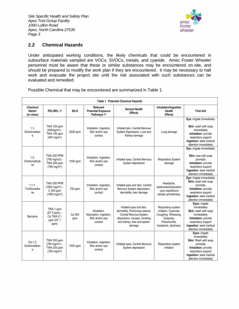
Site Specific Health and Safety Plan Apex Tool Group Facility 1000 Lufkin Road Apex, North Carolina 27539 Page 3
2.2 Chemical Hazards Under anticipated working conditions, the likely chemicals that could be encountered in subsurface materials sampled are VOCs, SVOCs, metals, and cyanide. Amec Foster Wheeler personnel must be aware that these or similar substances may be encountered on-site, and should be prepared to modify the work plan if they are encountered. It may be necessary to halt work and evacuate the project site until the risk associated with such substances can be evaluated and remedied. Possible Chemical that may be encountered are summarized in Table 1.
Table 1 Potential Chemical Hazards
Chemical Namea
(or class) PEL/REL (a) IDLH
Relevant Potential Exposure
Pathways (a)
Dermal Health Effects
Inhalation/Ingestion Health Effects
First Aid
1,1-Dichloroethan
e
TWA 100 ppm (400mg/m3) -
TWA 100 ppm (400 mg/m3)
3000 ppm Inhalation, Ingestion,
Skin and/or eye contact
Irritated skin, Central Nervous System Depression, Liver and
Kidney damage Lung damage
Eye: irrigate immediately
Skin: wash with soap immediately
Inhalation: provide respiratory support
Ingestion: seek medical attention immediately
1,2-Dichloroethyle
ne
TWA 200 PPM (790 mg/m3) - TWA 200 ppm (790 mg/m3)
1000 ppm Inhalation, Ingestion,
Skin and/or eye contact
Irritated eyes, Central Nervous System depression
Respiratory System damage
Eye: irrigate immediately
Skin: was with soap promptly
Inhalation: provide respiratory support
Ingestion: seek medical attention immediately
1,1,1-Trichloroetha
ne
TWA 350 PPM (1900 mg/m3) –
C 350 ppm (1900 mg/m3)
700 ppm Inhalation, Ingestion,
Skin and/or eye contact
Irritated eyes and skin, Central Nervous System depression,
dermatitis, liver damage
Headache, weakness/exhaustion
, poor equilibrium, cardiac arrhythmias,
Eye: irrigate immediately Skin: wash with soap
promptly Inhalation: provide respiratory support
Ingestion: seek medical attention immediately
Benzene
TWA 1 ppm (ST 5 ppm) – Ca TWA 0.1 ppm (ST 1
ppm)
Ca 500 ppm
Inhalation, Absorption, Ingestion,
Skin and/or eye contact
Irritated eyes and skin, dermatitis, Pulmonary edema,
Central Nervous System depression, nausea, vomiting and kidney, liver and spleen
damage
Respiratory system irritation, Cyanosis,
Coughing, Wheezing, Dyspnea,
Pneumonitis, headache, dizziness,
Eyes: irrigate immediately
Skin: wash with soap immediately
Inhalation: provide respiratory support
Ingestion: seek medical attention immediately
Cis-1,2-Dichloroethen
e
TWA 200 ppm (790 mg/m3) – TWA 200 ppm (790 mg/m3)
1000 ppm Inhalation, Ingestion,
Skin and/or eye contact
Irritated eyes, Central Nervous System depression
Respiratory system irritation
Eyes: irrigate immediately
Skin: Wash with soap promptly
Inhalation: provide respiratory support
Ingestion: seek medical attention immediately
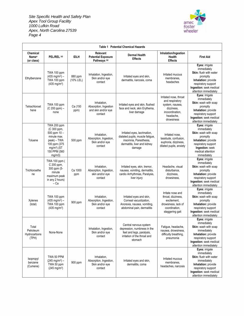
Site Specific Health and Safety Plan Apex Tool Group Facility 1000 Lufkin Road Apex, North Carolina 27539 Page 4
Table 1 Potential Chemical Hazards
Chemical Namea
(or class) PEL/REL (a) IDLH
Relevant Potential Exposure
Pathways (a)
Dermal Health Effects
Inhalation/Ingestion Health Effects
First Aid
Ethylbenzene
TWA 100 ppm (435 mg/m3) – TWA 100 ppm (435 mg/m3)
880 ppm (10% LEL)
Inhalation, Ingestion, Skin and/or eye
contact
Irritated eyes and skin, dermatitis, narcosis, coma
Irritated mucous membranes, headaches
Eyes: irrigate immediately
Skin: flush with water promptly
Inhalation: provide respiratory support
Ingestion: seek medical attention immediately
Tetrachloroethene
TWA 100 ppm (C 200 ppm) –
none
Ca (150 ppm)
Inhalation, Absorption, Ingestion and skin and/or eye
contact
Irritated eyes and skin, flushed face and neck, skin Erythema,
liver damage
Irritated nose, throat and respiratory
system, nausea, dizziness,
incoordination, headache, drowsiness
Eyes: Irrigate immediately
Skin: wash with soap promptly
Inhalation: provide respiratory support
Ingestion: seek medical attention immediately
Toluene
TWA 200 ppm (C 300 ppm,
500 ppm 10 – minute max. peak) – TWA 100 ppm (375 mg/m3) (ST
150 PPM (560 mg/m3)
500 ppm
Inhalation, Absorption, Ingestion,
Skin and/or eye contact
Irritated eyes, lacrimation, dialated pupils, muscle fatigue,
insomnia, Paresthesia, dermatitis, liver and kidney
damage
Irritated nose, lassitude, confusion, euphoria, dizziness,
dilated pupils, anxiety
Eyes: irrigate immediately
Skin: wash with soap promptly
Inhalation: provide respiratory support Ingestion: seek medical attention
immediately
Trichloroethene
TWA 100 ppm ( C 200 ppm, 300 ppm (5-
minute maximum peak in any 2 hours)
– Ca
Ca 1000 ppm
Inhalation, Absorption, Ingestion,
skin and/or eye contact
Irritated eyes, skin, tremor, nausea, vomiting, dermatitis, cardio Arrhythmias, Paralysis,
liver injury
Headache, visual disturbance, dizziness,
drowsiness,
Eyes: irrigate immediately
Skin: wash with soap promptly
Inhalation: provide respiratory support
Ingestion: seek medical attention immediately
Xylenes (total)
TWA 100 ppm (435 mg/m3) – TWA 100 ppm (435 mg/m3)
900 ppm
Inhalation, Absorption, Ingestion,
Skin and/or eye contact
Irritated eyes and skin, Corneal vacuolization,
Anorexia, nausea, vomiting, abdominal pain, dermatitis
Irritate nose and throat, dizziness,
excitement, drowsiness, lack of
coordination, staggering gait
Eyes: irrigate immediately
Skin: wash with soap promptly
Inhalation: provide respiratory support
Ingestion: seek medical attention immediately
Total Petroleum
Hydrocarbons (TPH)
None-None Inhalation, Ingestion,
Skin and/or eye contact
Central nervous system depression, numbness in the
feet and legs, paralysis, irritation of the throat and
stomach
Fatigue, headache, nausea, drowsiness, difficulty breathing,
pneumonia
Eyes: irrigate immediately
Skin: wash with soap immediately
Inhalation: provide respiratory support
Ingestion: seek medical attention immediately
Isopropyl benzene
(Cumene)
TWA 50 PPM (245 mg/m3) – TWA 50 ppm (245 mg/m3)
900 ppm
Inhalation, Absorption, Ingestion,
Skin and/or eye contact
Irritated eyes and skin, dermatitis, coma
Irritated mucous membranes,
headaches, narcosis
Eyes: irrigate immediately
Skin: flush with water immediately
Inhalation: provide respiratory support
Ingestion: seek medical attention immediately
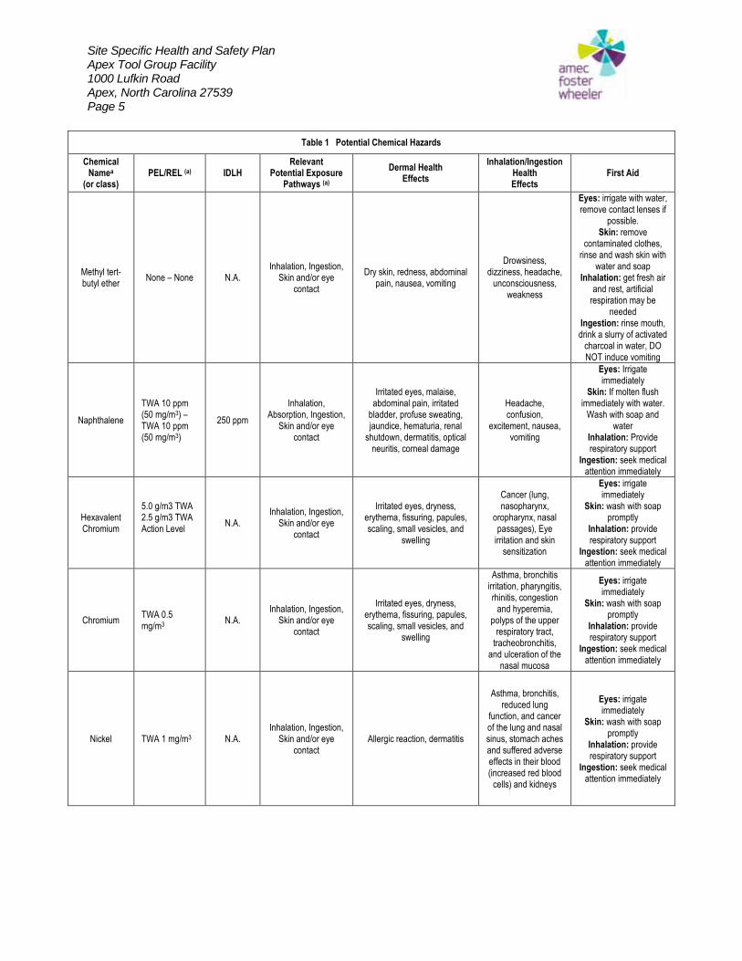
Site Specific Health and Safety Plan Apex Tool Group Facility 1000 Lufkin Road Apex, North Carolina 27539 Page 5
Table 1 Potential Chemical Hazards
Chemical Namea
(or class) PEL/REL (a) IDLH
Relevant Potential Exposure
Pathways (a)
Dermal Health Effects
Inhalation/Ingestion Health Effects
First Aid
Methyl tert-butyl ether
None – None N.A. Inhalation, Ingestion,
Skin and/or eye contact
Dry skin, redness, abdominal pain, nausea, vomiting
Drowsiness, dizziness, headache,
unconsciousness, weakness
Eyes: irrigate with water, remove contact lenses if
possible. Skin: remove
contaminated clothes, rinse and wash skin with
water and soap Inhalation: get fresh air
and rest, artificial respiration may be
needed Ingestion: rinse mouth, drink a slurry of activated
charcoal in water, DO NOT induce vomiting
Naphthalene
TWA 10 ppm (50 mg/m3) – TWA 10 ppm (50 mg/m3)
250 ppm
Inhalation, Absorption, Ingestion,
Skin and/or eye contact
Irritated eyes, malaise, abdominal pain, irritated
bladder, profuse sweating, jaundice, hematuria, renal
shutdown, dermatitis, optical neuritis, corneal damage
Headache, confusion,
excitement, nausea, vomiting
Eyes: Irrigate immediately
Skin: If molten flush immediately with water.
Wash with soap and water
Inhalation: Provide respiratory support
Ingestion: seek medical attention immediately
Hexavalent Chromium
5.0 g/m3 TWA 2.5 g/m3 TWA Action Level
N.A. Inhalation, Ingestion,
Skin and/or eye contact
Irritated eyes, dryness, erythema, fissuring, papules, scaling, small vesicles, and
swelling
Cancer (lung, nasopharynx,
oropharynx, nasal passages), Eye
irritation and skin sensitization
Eyes: irrigate immediately
Skin: wash with soap promptly
Inhalation: provide respiratory support
Ingestion: seek medical attention immediately
Chromium TWA 0.5 mg/m3
N.A. Inhalation, Ingestion,
Skin and/or eye contact
Irritated eyes, dryness, erythema, fissuring, papules, scaling, small vesicles, and
swelling
Asthma, bronchitis irritation, pharyngitis, rhinitis, congestion
and hyperemia, polyps of the upper
respiratory tract, tracheobronchitis,
and ulceration of the nasal mucosa
Eyes: irrigate immediately
Skin: wash with soap promptly
Inhalation: provide respiratory support
Ingestion: seek medical attention immediately
Nickel TWA 1 mg/m3 N.A. Inhalation, Ingestion,
Skin and/or eye contact
Allergic reaction, dermatitis
Asthma, bronchitis, reduced lung
function, and cancer of the lung and nasal sinus, stomach aches and suffered adverse effects in their blood (increased red blood
cells) and kidneys
Eyes: irrigate immediately
Skin: wash with soap promptly
Inhalation: provide respiratory support
Ingestion: seek medical attention immediately
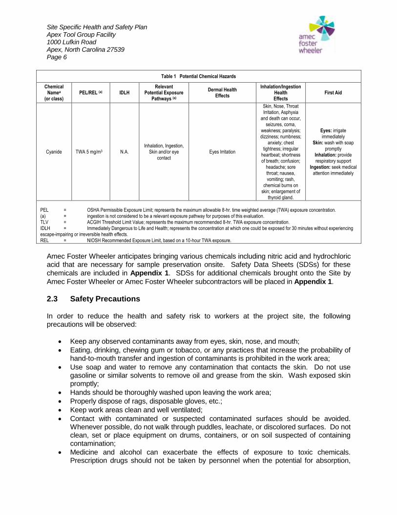
Site Specific Health and Safety Plan Apex Tool Group Facility 1000 Lufkin Road Apex, North Carolina 27539 Page 6
Table 1 Potential Chemical Hazards
Chemical Namea
(or class) PEL/REL (a) IDLH
Relevant Potential Exposure
Pathways (a)
Dermal Health Effects
Inhalation/Ingestion Health Effects
First Aid
Cyanide TWA 5 mg/m3 N.A. Inhalation, Ingestion,
Skin and/or eye contact
Eyes Irritation
Skin, Nose, Throat Irritation, Asphyxia
and death can occur, seizures, coma,
weakness; paralysis; dizziness; numbness;
anxiety; chest tightness; irregular
heartbeat; shortness of breath; confusion;
headache; sore throat; nausea, vomiting; rash,
chemical burns on skin; enlargement of
thyroid gland.
Eyes: irrigate immediately
Skin: wash with soap promptly
Inhalation: provide respiratory support
Ingestion: seek medical attention immediately
PEL = OSHA Permissible Exposure Limit; represents the maximum allowable 8-hr. time weighted average (TWA) exposure concentration. (a) = ingestion is not considered to be a relevant exposure pathway for purposes of this evaluation. TLV = ACGIH Threshold Limit Value; represents the maximum recommended 8-hr. TWA exposure concentration. IDLH = Immediately Dangerous to Life and Health; represents the concentration at which one could be exposed for 30 minutes without experiencing escape-impairing or irreversible health effects. REL = NIOSH Recommended Exposure Limit, based on a 10-hour TWA exposure.
Amec Foster Wheeler anticipates bringing various chemicals including nitric acid and hydrochloric acid that are necessary for sample preservation onsite. Safety Data Sheets (SDSs) for these
chemicals are included in Appendix 1. SDSs for additional chemicals brought onto the Site by
Amec Foster Wheeler or Amec Foster Wheeler subcontractors will be placed in Appendix 1.
2.3 Safety Precautions In order to reduce the health and safety risk to workers at the project site, the following precautions will be observed:
Keep any observed contaminants away from eyes, skin, nose, and mouth;
Eating, drinking, chewing gum or tobacco, or any practices that increase the probability of hand-to-mouth transfer and ingestion of contaminants is prohibited in the work area;
Use soap and water to remove any contamination that contacts the skin. Do not use gasoline or similar solvents to remove oil and grease from the skin. Wash exposed skin promptly;
Hands should be thoroughly washed upon leaving the work area;
Properly dispose of rags, disposable gloves, etc.;
Keep work areas clean and well ventilated;
Contact with contaminated or suspected contaminated surfaces should be avoided. Whenever possible, do not walk through puddles, leachate, or discolored surfaces. Do not clean, set or place equipment on drums, containers, or on soil suspected of containing contamination;
Medicine and alcohol can exacerbate the effects of exposure to toxic chemicals. Prescription drugs should not be taken by personnel when the potential for absorption,
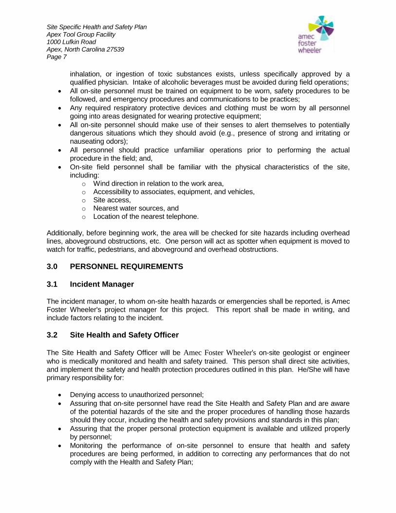
Site Specific Health and Safety Plan Apex Tool Group Facility 1000 Lufkin Road Apex, North Carolina 27539 Page 7
inhalation, or ingestion of toxic substances exists, unless specifically approved by a qualified physician. Intake of alcoholic beverages must be avoided during field operations;
All on-site personnel must be trained on equipment to be worn, safety procedures to be followed, and emergency procedures and communications to be practices;
Any required respiratory protective devices and clothing must be worn by all personnel going into areas designated for wearing protective equipment;
All on-site personnel should make use of their senses to alert themselves to potentially dangerous situations which they should avoid (e.g., presence of strong and irritating or nauseating odors);
All personnel should practice unfamiliar operations prior to performing the actual procedure in the field; and,
On-site field personnel shall be familiar with the physical characteristics of the site, including:
o Wind direction in relation to the work area, o Accessibility to associates, equipment, and vehicles, o Site access, o Nearest water sources, and o Location of the nearest telephone.
Additionally, before beginning work, the area will be checked for site hazards including overhead lines, aboveground obstructions, etc. One person will act as spotter when equipment is moved to watch for traffic, pedestrians, and aboveground and overhead obstructions.
3.0 PERSONNEL REQUIREMENTS
3.1 Incident Manager The incident manager, to whom on-site health hazards or emergencies shall be reported, is Amec Foster Wheeler's project manager for this project. This report shall be made in writing, and include factors relating to the incident.
3.2 Site Health and Safety Officer
The Site Health and Safety Officer will be Amec Foster Wheeler's on-site geologist or engineer
who is medically monitored and health and safety trained. This person shall direct site activities, and implement the safety and health protection procedures outlined in this plan. He/She will have primary responsibility for:
Denying access to unauthorized personnel;
Assuring that on-site personnel have read the Site Health and Safety Plan and are aware of the potential hazards of the site and the proper procedures of handling those hazards should they occur, including the health and safety provisions and standards in this plan;
Assuring that the proper personal protection equipment is available and utilized properly by personnel;
Monitoring the performance of on-site personnel to ensure that health and safety procedures are being performed, in addition to correcting any performances that do not comply with the Health and Safety Plan;
Site Specific Health and Safety Plan Apex Tool Group Facility 1000 Lufkin Road Apex, North Carolina 27539 Page 8
Coordinating safety procedures with the local authorities;
Advising the project manager on health and safety matters relative to the site;
Performing periodic monitoring for organic vapors;
Posting a copy of the Health and Safety Plan at the site with emergency telephone numbers and directions to the nearest telephone;
Calibrating monitoring equipment and recording results on an instrument calibration log;
Assuring that on-site personnel observe the appropriate work zones and decontamination procedures;
Making "buddy" assignments for personnel; and,
Reporting any safety violations to the Project Manager. In addition to these responsibilities, the site health and safety officer shall be responsible for making modifications to the Health and Safety Plan during the course of the project, based upon the results of the site monitoring program.
3.3 Project Personnel Project personnel involved in on-site investigations and operations are responsible for:
Informing themselves of the guidelines outlined within the Health and Safety Plan, especially any aspects that they do not understand;
Taking reasonable precautions to prevent injury to themselves and to their fellow employees; being alert to potentially harmful situations;
Performing only those tasks that they believe they can do safely and immediately reporting any accidents and/or unsafe conditions to the Site Health and Safety Officer;
Notifying the Site Health and Safety Officer of any special medical conditions (i.e., allergies, pregnancy, diabetes) and, if necessary, assuring that on-site personnel are aware of any such conditions;
Preventing spillage to the extent possible. In the event that a spillage occurs, contain the spillage and clean up the spill using clean up procedures as directed by the Site Health and Safety Officer;
Avoiding splashing of contaminated materials to the extent possible;
Practicing good housekeeping by keeping everything orderly and out of potentially harmful situations;
Reporting injuries; and,
Executing the "buddy system" so that each on-site worker is responsible for keeping track of their partner.
On-site personnel are responsible for implementing this Health and Safety Plan in order to promote a safe work environment.
Site Specific Health and Safety Plan Apex Tool Group Facility 1000 Lufkin Road Apex, North Carolina 27539 Page 9
4.0 DESIGNATION OF THE LEVELS OF PROTECTION Level D personal protective equipment will be utilized during the subsurface investigation activities with contingencies for Level C protection. If deemed necessary, Level C protection shall include respirators fitted with dust pre-mist filters, and organic vapor cartridges. If conditions warrant Level C personnel protection, personnel must don the required protective equipment or leave the work area until conditions return to acceptable Level D conditions.
4.1 Level D Personal Protection Equipment Level D protection will be selected when it has been determined that there is no possibility of skin contact with contamination or respiratory hazard. This level is primarily a work uniform. Level D Equipment shall include the following:
Clothing, low static, natural fiber (e.g., cotton) no loose or dangling clothing allowed because of the proximity to power operated equipment;
Hard hat; ANSI Z89 nonmetallic hard hat;
Safety glasses; ANSI Z87 glasses with rigid side shields. Prescription glasses must meet ANSI Z87 or be fitted with approved "fit over" safety glasses;
Safety shoes; leather or chemically-resistant, steel toe;
Gloves; inner PVC, outer cotton or leather work glove, if appropriate; and,
Hearing protection; while on-site, have hearing protection available. Use hearing protection when noise levels exceed 85 decibels.
4.2 Modified Level C Personal Protection Equipment Modified Level C protection will be selected when the types and concentrations of material is known, or reasonably assumed to be not greater than the protection factors associated with N-95 disposable masks, and exposure to the unprotected areas of the body is unlikely to cause harm. Modified Level C Equipment, in addition to those items already specified under Level D requirements is as follows:
N-95 Disposable Masks;
Clothing; outer garments, one or two piece, chemical resistant fabric; and,
Gloves; inner PVC glove, outer chemical resistant glove.
4.3 Level C Personal Protection Equipment Level C protection will be selected when the types and concentrations of material is known, or reasonably assumed to be not greater than the protection factors associated with air-purifying respirators, and exposure to the unprotected areas of the body is unlikely to cause harm. Level C Equipment, in addition to those items already specified under Level D requirements is as follows:
Site Specific Health and Safety Plan Apex Tool Group Facility 1000 Lufkin Road Apex, North Carolina 27539 Page 10
Respirator; full face, air purifying, cartridge type fitted with dust pre-mist filters and organic vapor cartridges;
Clothing; outer garments, one or two piece, chemical resistant fabric; and,
Gloves; inner PVC glove, outer chemical resistant glove. If conditions of the project site require a level of protection beyond Level C, then project operations shall cease and personnel shall evacuate the site while the increased hazard is evaluated.
5.0 DELINEATION OF THE WORK AREA The work area shall be defined as the area adjacent to where environmental work is being performed. Traffic cones and/or barricades shall be used to identify the work area and control
access to the work area. Site drawings are provided in Appendix 2.
6.0 CONTROL PROCEDURES
6.1 Work Limitations To control access to the work zone and the decontamination zone, barricades or warning tape shall be used to delineate these areas. This will serve to protect unauthorized personnel from physical injury or chemical exposure. Along with the control procedures the following safety requirements shall be observed:
The work area is to be restricted to authorized personnel and their equipment. Personnel and equipment should be kept to a minimum, consistent with effective site operations. The work area should be barricaded or roped off, to prevent access by unauthorized personnel and/or their vehicles; and,
No vehicular movement is allowed in the work area while work activities are underway. If the level of contamination encountered at the site requires the use of personnel protective equipment above Level D, then a barricaded walkway shall be constructed from the work zone to the decontamination zone. The purpose of the walkway is to limit the spread of contaminated materials at the project site, and reduce the area that will require further decontamination efforts.
6.2 Traffic Control Plans To protect the safety of all personnel working at this facility, Amec Foster Wheeler should implement the following Traffic Control Plans:
6.2.1 Performing Tasks in Traffic Areas (other than roadways)
All employees are required to wear high-visibility clothing at all times while onsite;
Use a minimum of 2 additional traffic control measures/devices; and,
A buddy system should be implemented in areas considered high risk.
Site Specific Health and Safety Plan Apex Tool Group Facility 1000 Lufkin Road Apex, North Carolina 27539 Page 11
6.2.2 Performing Tasks in Roadways
All employees are required to wear high-visibility clothing at all times while onsite;
A buddy system should be implemented in areas considered high risk;
Use a minimum of 2 additional traffic control measures/devices; and,
Use lane closure procedures following the appropriate regulatory standards (e.g. DOT/OSHA, National Highway Safety Uniform Traffic Control), local standards or Global Remediation minimum standards.
6.2.3 Long Duration Work (GeoProbe operations, drilling, trenching, etc.)
Use cones and barricades as needed to protect the work area;
Use flags as needed to protect the work area; and,
Use “Men Working” signs for advance warning to motorists.
6.2.4 Examples of Precautionary Measures/Controls
Place wells in safe locations;
Be alert, pay attention, watch, and listen for cars;
Wear reflective vest and bright clothing;
Use cones at each point of service;
Place pole mounted warning flags inside of cones;
Park vehicle in order to block traffic;
Use flashing barricades;
Use light bars or reflective lights on trucks;
Consult site manager about traffic evaluation;
Avoid prolonged time in traffic lanes;
Don’t work around corners, make yourself visible;
Stay upright as much as possible;
Give notice to vehicle drivers nearby;
Trust no one, even if they see you;
Use buddy system;
Work during non-peak hours;
Always face traffic;
Use floodlights in darkness;
Obtain police assistance for roadwork and local permits as required; and,
Place letter on windshields to warn drivers – “CAUTION – Work Area Behind Vehicle”.
6.2.5 Examples of Traffic Control Devices
Traffic cones (at least two) in combination with Standard Warning Flag. Total height at least 42 inches (1 meter);
Molded Plastic Barricades;
Type I and II Barricades;
Use of Vehicle to block traffic;
Use of light bars or reflective lights on trucks;
Site Specific Health and Safety Plan Apex Tool Group Facility 1000 Lufkin Road Apex, North Carolina 27539 Page 12
Buddy System;
Place letter on wind;
Use floodlights in darkness;
Placement of “Caution-Work Area” signs; and,
Plastic Channelizer (Orange Barrels).
6.3 Decontamination Procedures The purpose of decontamination is primarily to limit the spread of contaminated materials. This is accomplished through a step-by-step procedure whereby the protective clothing and equipment are disposed, or washed.
6.3.1 Personnel Decontamination When exiting the work area, all personnel shall follow the decontamination procedures outlined in Sections 6.2.3 and 6.2.4. Level D procedures are covered in paragraph 6.2.3 and Level C procedures are outlined in paragraph 6.2.4.
6.3.2 Equipment Decontamination The Site Health and Safety Officer shall be responsible to assure that equipment is properly decontaminated and checked prior to being removed off-site. Reasonable efforts should be made to remove contamination by wiping, brushing or washing surfaces. At a minimum, visual indication of contamination shall be removed and no organic vapors detectable above background should remain. Equipment should be reasonably clean, dry, unstained, and free from deposits, encrustations, or discoloration.
6.3.3 Level D Decontamination
Remove trackable or loose materials;
Remove work gloves and monitor clothing and hands; and,
Thoroughly wash hands and face.
6.3.4 (Modified) Level C Decontamination The steps for (Modified) Level C decontamination begin with gloves being washed and rinsed, then tape being removed. Employee then initiates suit and safety boot wash and rinse, then removal of safety boots, followed by suit removal. Next, the face piece should be removed.
6.4 Disposal of Materials Generated During Field Work Contaminated materials may be generated while conducting site environmental activities. Amec Foster Wheeler personnel shall be aware of the proper means of disposal for such materials. The following guidelines will be observed when dealing with such materials:
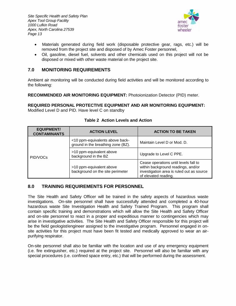
Site Specific Health and Safety Plan Apex Tool Group Facility 1000 Lufkin Road Apex, North Carolina 27539 Page 13
Materials generated during field work (disposable protective gear, rags, etc.) will be removed from the project site and disposed of by Amec Foster personnel,
Oil, gasoline, diesel fuel, solvents and other chemicals used on this project will not be disposed or mixed with other waste material on the project site.
7.0 MONITORING REQUIREMENTS Ambient air monitoring will be conducted during field activities and will be monitored according to the following:
RECOMMENDED AIR MONITORING EQUIPMENT: Photoionization Detector (PID) meter.
REQUIRED PERSONAL PROTECTIVE EQUIPMENT AND AIR MONITORING EQUIPMENT: Modified Level D and PID. Have level C on standby
Table 2 Action Levels and Action
EQUIPMENT/
CONTAMINANTS ACTION LEVEL ACTION TO BE TAKEN
PID/VOCs
<10 ppm-equivalents above back-ground in the breathing zone (BZ).
Maintain Level D or Mod. D.
>10 ppm-equivalent above background in the BZ
Upgrade to Level C PPE.
>10 ppm-equivalent above background on the site perimeter
Cease operations until levels fall to within background readings, and/or investigation area is ruled out as source of elevated reading.
8.0 TRAINING REQUIREMENTS FOR PERSONNEL The Site Health and Safety Officer will be trained in the safety aspects of hazardous waste investigations. On-site personnel shall have successfully attended and completed a 40-hour hazardous waste Site Investigation Health and Safety Trained Program. This program shall contain specific training and demonstrations which will allow the Site Health and Safety Officer and on-site personnel to react in a proper and expeditious manner to contingencies which may arise in investigative activities. The Site Health and Safety Officer responsible for this project will be the field geologist/engineer assigned to the investigative program. Personnel engaged in on-site activities for this project must have been fit tested and medically approved to wear an air-purifying respirator. On-site personnel shall also be familiar with the location and use of any emergency equipment (i.e. fire extinguisher, etc.) required at the project site. Personnel will also be familiar with any special procedures (i.e. confined space entry, etc.) that will be performed during the assessment.
Site Specific Health and Safety Plan Apex Tool Group Facility 1000 Lufkin Road Apex, North Carolina 27539 Page 14
9.0 WEATHER RELATED HAZARDS Generally, environmental activities will be conducted outside, and therefore are subject to weather conditions. Precipitation, or extremes in temperature, can pose health or safety hazards and shall be considered. Extra care shall be taken when working in the rain, and operations shall cease in the presence of lighting. AMEC personnel shall be able to recognize the symptoms of heat and cold stress, and take the appropriate measures to alleviate them. A location will be designated outside the work area where personnel can take rest breaks from extreme weather conditions.
9.1 Heat Stress Personnel are likely to experience heat stress on hot, humid days with little or no breeze, especially if the ambient temperature is greater than 90oF. Conditions that can occur from heat stress are heat cramps, heat exhaustion and heat stroke. Heat cramps are muscular pains and spasms brought on by the loss of water and electrolytes from heavy sweating. Proper treatment includes removing the affected person to a cooler place and providing small sips of water to drink if they want them. Heat exhaustion is a more severe condition than heat cramps. Symptoms include pale, moist skin, heavy sweating, dilated pupils, headache, dizziness, nausea and vomiting. Treatment for this condition consists of removing the affected person to a cooler place, provide small sips of water at approximately fifteen minute intervals if the person can tolerate it, and placing towels moistened with cool water on the victim’s skin. The victim should be closely monitored to determine if their condition is improving under this treatment. If no improvement is observed within a half hour to an hour, professional medical care should be sought to treat this condition. Heat stroke is the most severe form of heat stress. This condition occurs when the system which regulates body temperature breaks down, often the victim stops sweating. Symptoms include a very high body temperature, red skin color, and very small pupils. Heat stroke is a very serious condition and professional medial treatment should be obtained for the victim as soon as possible. First aid includes removing the affected person to a cooler place, treating for shock, and bathing the victim with towels moistened with cool water.
9.2 Cold Stress Personnel can experience cold stress on cool, humid, windy days especially when the ambient temperature is below 40oF. Personnel exposed to cold stress can suffer from hypothermia or frostbite. Hypothermia occurs when the body temperature is depressed below 98.6oF. Symptoms include shivering, dizziness, numbness, weakness, confusion, and drowsiness. Treatment includes placing the affected person in a warm area sheltered from wind or rain, replacing wet clothing with dry, and if the victim is conscious, provide warm beverages and food (note: do not provide alcohol or stimulants to victims of cold stress).
Site Specific Health and Safety Plan Apex Tool Group Facility 1000 Lufkin Road Apex, North Carolina 27539 Page 15
Frostbite occurs when ice crystals form in body tissues, and restrict the flow of blood to the injured areas. Frostbite most commonly occurs at the body's extremities (e.g., fingers and toes) and on exposed skin (e.g., nose and ears). Symptoms of frostbite include white or grayish skin color, a feeling of pain in the early stages; often the affected area feels cold and numb. Treatment should include removing the affected person to a warm place, sheltered from the wind or rain, and allowing the affected area to thaw. Professional medical treatment should be sought for moderate or severe cases of frostbite.
10.0 MEDICAL REQUIREMENTS
10.1 Health Monitoring AMEC provides annual medical surveillance programs for employees who have risk of exposure to environmental waste products. AMEC personnel on-site during the subject project shall be active in AMEC's medical surveillance program. This program is based on recommendations within the NIOSH/OSHA/USCG/EPA Occupational Safety and Health Guidance Manual for Hazardous Waste Site Activities and includes the following areas of concern: 1. Occupational History; 2. Medical History; 3. Physical Examination; 4. Ophthalmology Assessment; 5. Audiometry; 6. Chest X-Ray; 7. Electrocardiogram; 8. Blood and Urine Screening; and, 9. Pulmonary Function Test.
10.2 Site Specific Requirements Due to the nature of the substances used or stored at the subject site (potentially chlorinated solvents), no specific medical monitoring of personnel will be required while the assessment is being conducted. However, if a worker suffers a chemical exposure, or experiences symptoms indicating that such an exposure may have occurred, then that worker will be checked by a physician to determine if he/she has suffered any adverse health effects as a result of this exposure.
11.0 ON-SITE EMERGENCIES
11.1 Emergency Procedures 11.1.1 Emergency Situation Site activities present a potential risk to on-site personnel. During routine operations, a risk is minimized by establishing good work practices, staying alert, and using proper personal protective equipment. Unpredictable events such as physical injury, chemical exposure, or fires may occur and must be anticipated. If an emergency occurs these procedures should be followed:
Site Specific Health and Safety Plan Apex Tool Group Facility 1000 Lufkin Road Apex, North Carolina 27539 Page 16
In the event that any on-site personnel experiences adverse effects or symptoms of exposure while on the scene, AMEC personnel shall immediately halt work and act according to the instructions provided by the Site Health and Safety Officer;
The discovery of a condition that would suggest the existence of a situation more hazardous than anticipated, should result in the evacuation of AMEC personnel, followed by re-evaluation of the hazard and the level of personal protection required;
In the event of an incident, the Project Manager and the Site Health and Safety Officer shall prepare a memorandum detailing all aspects of the incident. Follow-up action must be taken to correct the situation that caused the incident.
11.1.2 Project Telephone The nearest telephone to the project site is the cell phone located on AMEC’s onsite Health and Safety officer or on site geologist.
11.1.3 Emergency Communications The "buddy system" will be enforced for field activities involving potential exposure to hazardous or toxic materials, and within the work zone. Each person will observe their partner for symptoms of chemical over exposures or heat stress and provide emergency assistance when warranted.
11.1.4 Emergency Signals The following emergency signals shall be used:
Grasping throat with hand: Emergency - help me
Thumbs up: OK; understood
Grasping buddy's wrist: Leave site now.
11.1.5 Emergency Organizations A list of the organizations whose assistance might be required to deal with an on-site emergency is provided, along telephone number, and a point of contact (if relevant).
Ambulance Service - 911
Fire Department - 911
Police Department - 911
North Carolina Emergency Management (NC DPS) - 800-585-0368 It may be necessary to coordinate activities with these organizations prior to beginning project operations.
11.1.6 Emergency Evacuation If an emergency arises which requires personnel to evacuate the project site, personnel shall leave in an upwind direction to a point where safe deliberation can be made of how to respond to the emergency situation.
Site Specific Health and Safety Plan Apex Tool Group Facility 1000 Lufkin Road Apex, North Carolina 27539 Page 17
11.1.7 Emergency Equipment A 20-pound fire extinguisher shall be readily available at the project site, capable of extinguishing class A-B-C fires. On-site personnel shall be familiar with its proper use. A first-aid kit will also be available on-site, in the event a worker suffers a physical injury. On-site personnel certified in first aid can administer treatment and/or CPR to an injured worker.
11.2 Emergency Medical Care
11.2.1 Local Hospital The closest hospital is the Wakemed Apex Healthplex located at 120 Healthplex Way, Apex, NC 27502. The telephone number for the hospital is (919) 350-4300. To reach the hospital from the project site: Direction to Wakemed Apex Healthplex from Apex Tools Group Facility:
1. Head southwest toward Lufkin Rd (0.1 mi.) 2. Turn left onto Lufkin Rd (0.2 mi.) 3. Turn right onto NC-55 W/E Williams St. (2.7 mi.) 4. Turn left onto Healthplex Way. Destination will be on the left. (0.2 mi.)
11.2.2 Medical Clinic Injuries that are not serious will be treated at the nearest Convenient Care Center.
11.2.3 Emergency Drills The Site Health and Safety Officer may hold periodic emergency drills, to train on-site personnel in the correct procedures to follow in the event of an emergency. Special emphasis will be placed on the proper response to a fire or chemical exposure injury.
12.0 SUMMARY Amec Foster personnel involved with the scope of work for the subject project shall be familiar with the possible hazards involved, the safety procedures, and other inherent factors outlined in this plan. Prior to the commencement of work on the project, the Project Manager and the Site Health and Safety Officer should discuss general procedures to be implemented, addressing local safety and health requirements and any site-specific conditions that may require additional precautions.

APPENDIX 1
SAFETY DATA SHEETS FOR CHEMICALS BROUGHT ON-SITE
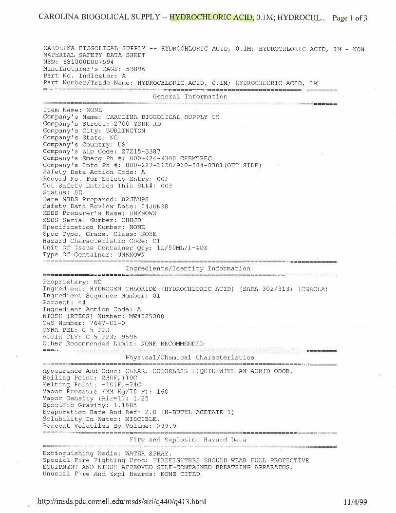
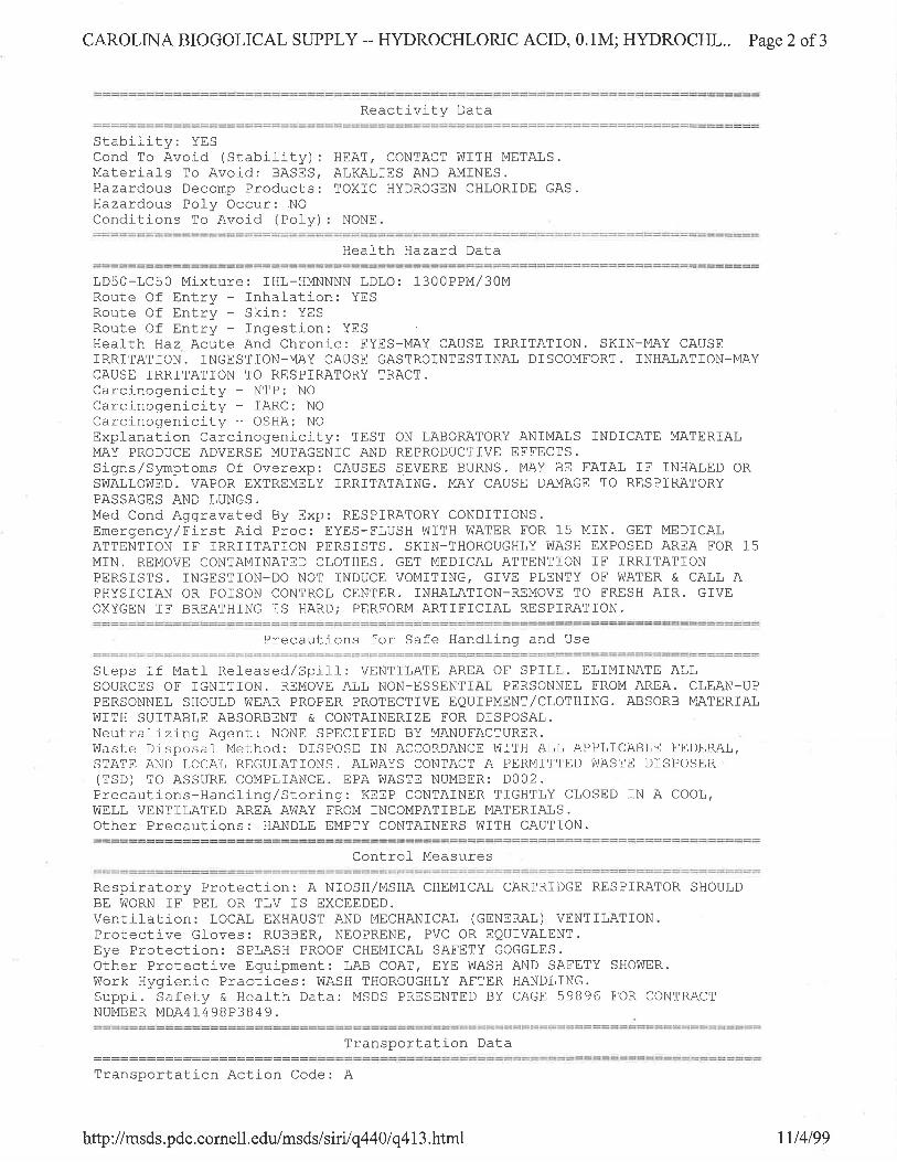
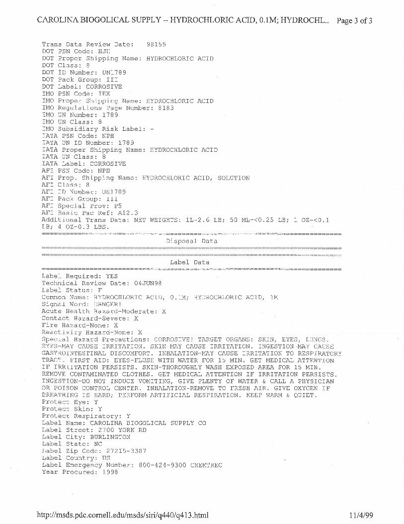
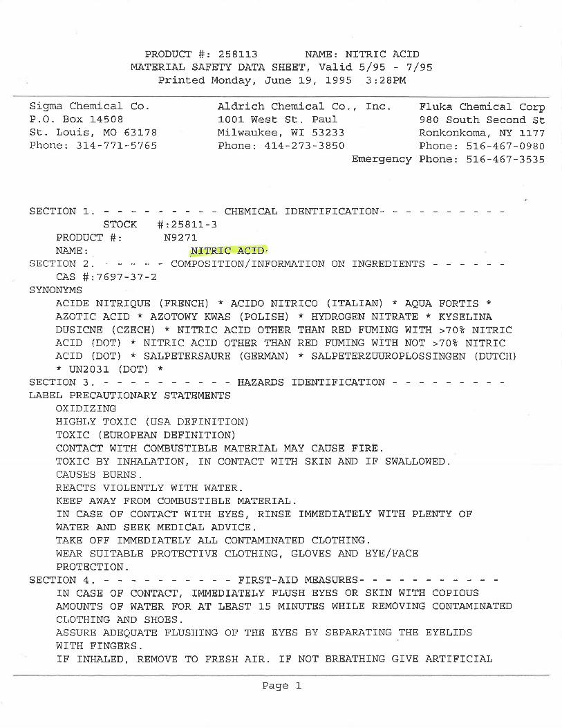
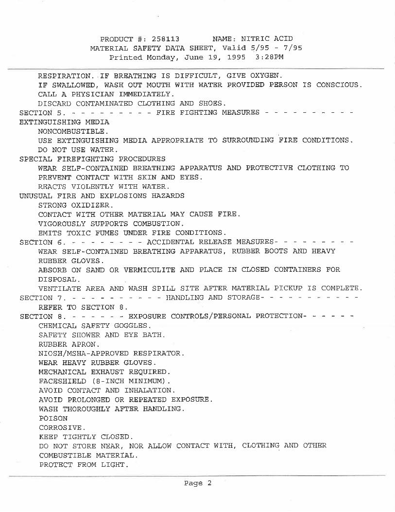
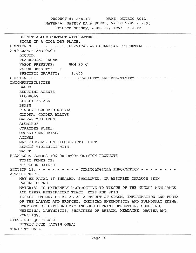

APPENDIX 2
SITE DRAWINGS
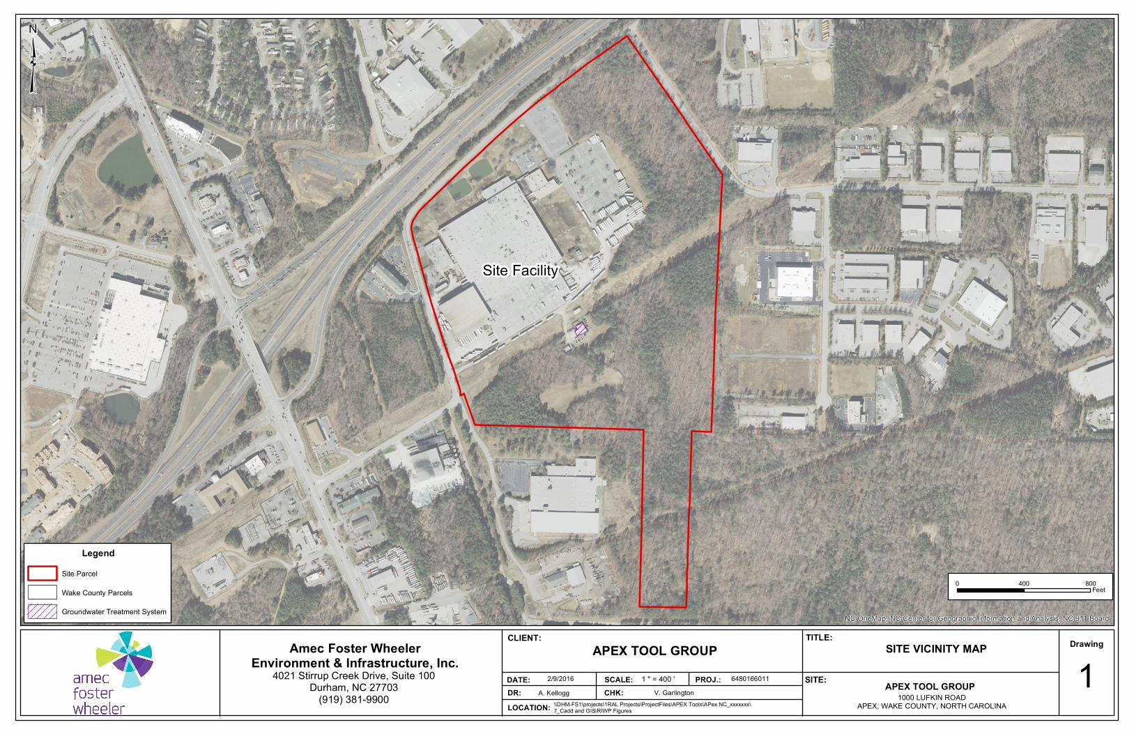
Site Facility
NC OneMap, NC Center for Geographic Information and Analysis, NC 911 Board
0 800400Feet
LegendSite Parcel
Wake County Parcels
Groundwater Treatment System
³
APEX TOOL GROUP1000 LUFKIN ROAD
APEX, WAKE COUNTY, NORTH CAROLINA
Drawing
DR: CHK:DATE:
SITE VICINITY MAP
1A. Kellogg V. Garlington
2/9/2016
CLIENT:
PROJ.: 6480166011
TITLE:
SCALE: SITE:
Amec Foster WheelerEnvironment & Infrastructure, Inc.
4021 Stirrup Creek Drive, Suite 100Durham, NC 27703
(919) 381-9900LOCATION: \\DHM-FS1\projects\1RAL Projects\ProjectFiles\APEX Tools\APex NC_xxxxxxx\
7_Cadd and GIS\RIWP Figures
APEX TOOL GROUP1 " = 400 '
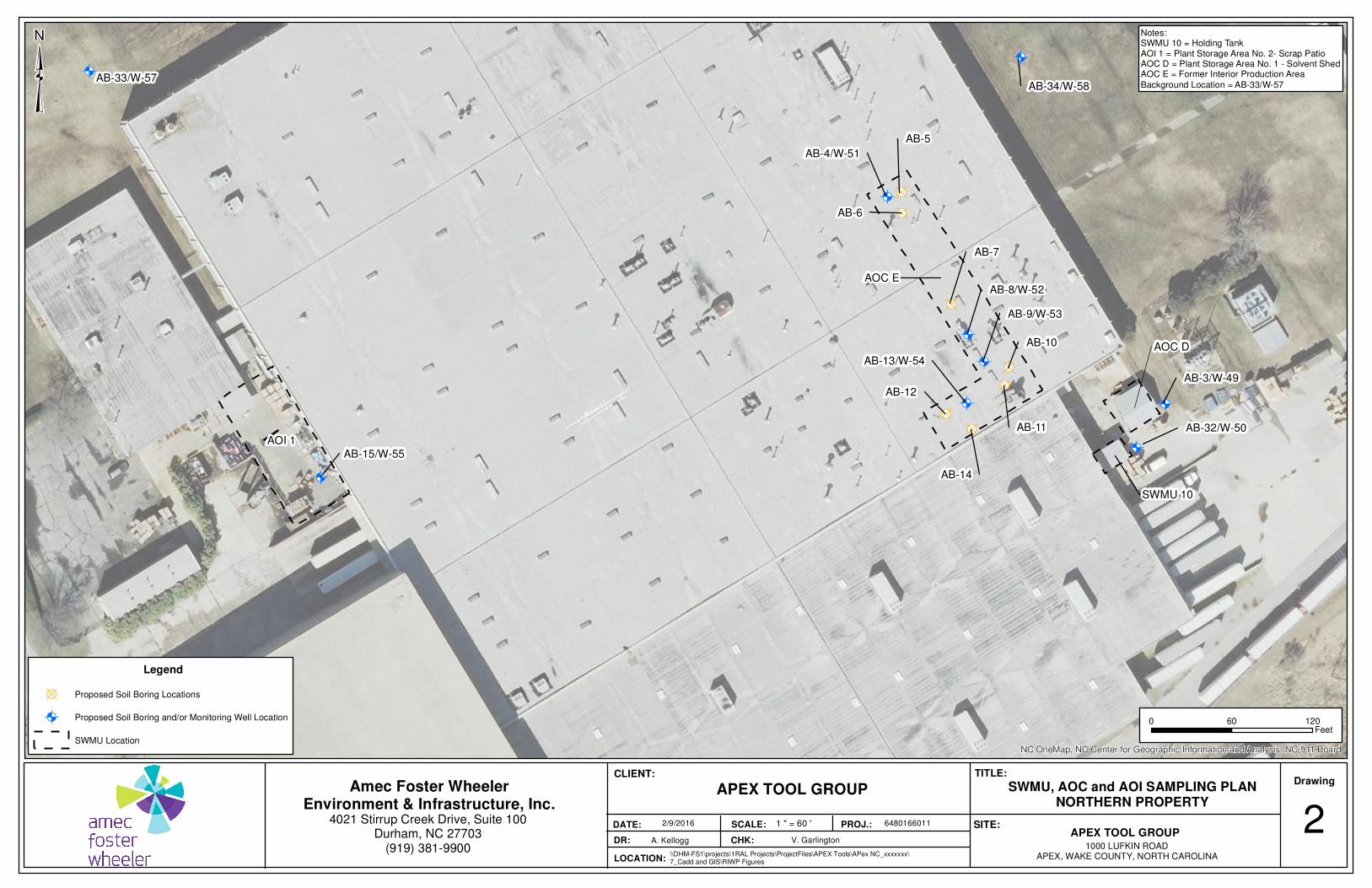
Ò!(
Ò!(
Ò!(
Ò!(
Ò!(
Ò!(
Ò!(
Ò!(
Ò!(
!B
!B
!B
!B
!B
!B
!B
SWMU 10
AOC E
AB-4/W-51
AB-5
AB-6
AB-7
AB-10
AB-11
AB-14
AB-12
AB-13/W-54
AB-8/W-52
AB-9/W-53
AB-33/W-57AB-34/W-58
AOI 1
AOC D
AB-15/W-55
AB-32/W-50
AB-3/W-49
NC OneMap, NC Center for Geographic Information and Analysis, NC 911 Board
0 12060Feet
Legend
!B Proposed Soil Boring Locations
Ò!( Proposed Soil Boring and/or Monitoring Well Location
SWMU Location
³
APEX TOOL GROUP1000 LUFKIN ROAD
APEX, WAKE COUNTY, NORTH CAROLINA
Drawing
DR: CHK:
DATE:
SWMU, AOC and AOI SAMPLING PLANNORTHERN PROPERTY
2A. Kellogg V. Garlington
2/9/2016
CLIENT:
PROJ.: 6480166011
TITLE:
SCALE: SITE:
Amec Foster WheelerEnvironment & Infrastructure, Inc.
4021 Stirrup Creek Drive, Suite 100Durham, NC 27703
(919) 381-9900LOCATION:
\\DHM-FS1\projects\1RAL Projects\ProjectFiles\APEX Tools\APex NC_xxxxxxx\7_Cadd and GIS\RIWP Figures
APEX TOOL GROUP
1 " = 60 '
Notes:SWMU 10 = Holding TankAOI 1 = Plant Storage Area No. 2- Scrap PatioAOC D = Plant Storage Area No. 1 - Solvent ShedAOC E = Former Interior Production Area
Background Location = AB-33/W-57

!B
!B
!B
!B
!B
!B
!B
!B!B
!B
!B
!B!B
!B
!B
!B
!B
!B
!B
!B
!B
!B
!B
!B
Ò!(Ò!(
Ò!(
Ò!(
Ò!(
Ò!(
Ò!(
Ò!(
Ò!(
Ò!(
Ò!(
Ò!(
Ò!(
Ò!(
Ò!(
Ò!(
Ò!(
Ò!(
Ò!(
Ò!(
Ò!(
Ò!(
Ò!(
SWMU 8
AB-30AB-19
W-45
AB-18
AB-16/W-47
AB-35/W-59
SWMU 2*
AOC B/SWMU 11
SWMU 4 SWMU 3*
SWMU 5
SWMU 6
AOC A
SWMU 7SWMU 9
AOC C
AB-17/W-48
W-46
AB-2/W-56
W-44
AB-22AB-23
AB-24AB-25
AB-26AB-27
AB-21
AB-20
AB-1
AB-28AB-29
AB-31
NC OneMap, NC Center for Geographic Information and Analysis, NC 911 Board
0 8040Feet
Legend
Ò!( Proposed Monitoring Well Location
!B Proposed Soil Boring Locations
Process Waste Water Lines
SWMU/AOC Location
³
APEX TOOL GROUP1000 LUFKIN ROAD
APEX, WAKE COUNTY, NORTH CAROLINA
Drawing
DR: CHK:DATE:
SWMU AND AOC SAMPLING PLANCENTRAL PROPERTY 3
A. Kellogg V. Garlington2/9/2016
CLIENT:
PROJ.: 6480166011
TITLE:
SCALE: SITE:
Amec Foster WheelerEnvironment & Infrastructure, Inc.
4021 Stirrup Creek Drive, Suite 100Durham, NC 27703
(919) 381-9900LOCATION: \\DHM-FS1\projects\1RAL Projects\ProjectFiles\APEX Tools\APex NC_xxxxxxx\
7_Cadd and GIS\RIWP Figures
APEX TOOL GROUP1 " = 40 '
Notes:SWMU 2 = Sludge PondSWMU 3 = Sludge Drying BedsSWMU 4 = Drum Storage AreaSWMU 5 = ClarifierSWMU 6 = Sludge Treatment TanksSWMU 7 = Chromic Acid Waste TankSWMU 8 = Cyanide Waste TankSWMU 9 = Iron Etching TankSWMU 11 = Wastewater Treatment BuildingAOC A = Caustic TankAOC B = Wastewater Treatment LabAOC C = Sulfuric Acid Tank* = SWMU ClosedBackground Location = AB-35/W-58
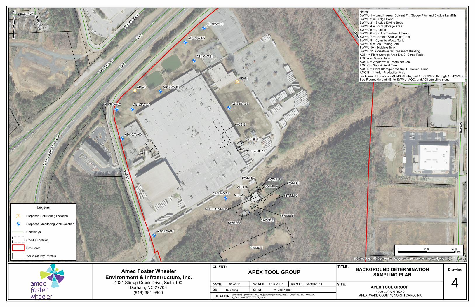
Ò!( Ò!(
Ò!(
Ò!(
Ò!(
Ò!(
Ò!(
Ò!(
Ò!(
Ò!(
!B
!B
AB-42/W-66
AB-41/W-65
AB-40/W-64
AB-39/W-63
AB-38/W-62
AB-37/W-61
AB-36/W-60
AB-35/W-59
AB-34/W-58AB-33/W-57
AB-44
AB-43
SWMU 1
AOC E
AOI 1
SWMU 2
SWMU 4 SWMU 3
AOC B/SWMU 11
AOC D
SWMU 5
AOC A
SWMU 6SWMU 7
SWMU 10
SWMU 9SWMU 8
AOC C
US 1
LUFKIN
BURM
A
CLASSIC
US 1 EXIT 95
E WILL
IAMS S
T TO U
S 1
SCHIEFFELINSEAGRAM MARKHAM
US 1
NC OneMap, NC Center for Geographic Information and Analysis, NC 911 Board
0 400200Feet
Legend!B Proposed Soil Boring Location
Ò!( Proposed Monitoring Well Location
Roadways
SWMU Location
Site Parcel
Wake County Parcels
³
APEX TOOL GROUP1000 LUFKIN ROAD
APEX, WAKE COUNTY, NORTH CAROLINA
Drawing
DR: CHK:DATE:
BACKGROUND DETERMINATIONSAMPLING PLAN 4
D. Young V. Garlington9/2/2016
CLIENT:
PROJ.: 6480166011
TITLE:
SCALE: SITE:
Amec Foster WheelerEnvironment & Infrastructure, Inc.
4021 Stirrup Creek Drive, Suite 100Durham, NC 27703
(919) 381-9900LOCATION: \\DHM-FS1\projects\1RAL Projects\ProjectFiles\APEX Tools\APex NC_xxxxxxx\
7_Cadd and GIS\RIWP Figures
APEX TOOL GROUP1 " = 200 '
Notes:SWMU 1 = Landfill Area (Solvent Pit, Sludge Pits, and Sludge Landfill)SWMU 2 = Sludge PondSWMU 3 = Sludge Drying BedsSWMU 4 = Drum Storage AreaSWMU 5 = ClarifierSWMU 6 = Sludge Treatment TanksSWMU 7 = Chromic Acid Waste TankSWMU 8 = Cyanide Waste TankSWMU 9 = Iron Etching TankSWMU 10 = Holding TankSWMU 11 = Wastewater Treatment BuildingAOI 1 = Plant Storage Area No. 2- Scrap PatioAOC A = Caustic TankAOC B = Wastewater Treatment LabAOC C = Sulfuric Acid TankAOC D = Plant Storage Area No. 1 - Solvent ShedAOC E = Interior Production AreaBackground Location = AB-43, AB-44, and AB-33/W-57 through AB-42/W-66See Figures 4A and 4B for SWMU, AOC, and AOI sampling plans
ATTACHMENT 1
IAR FORM
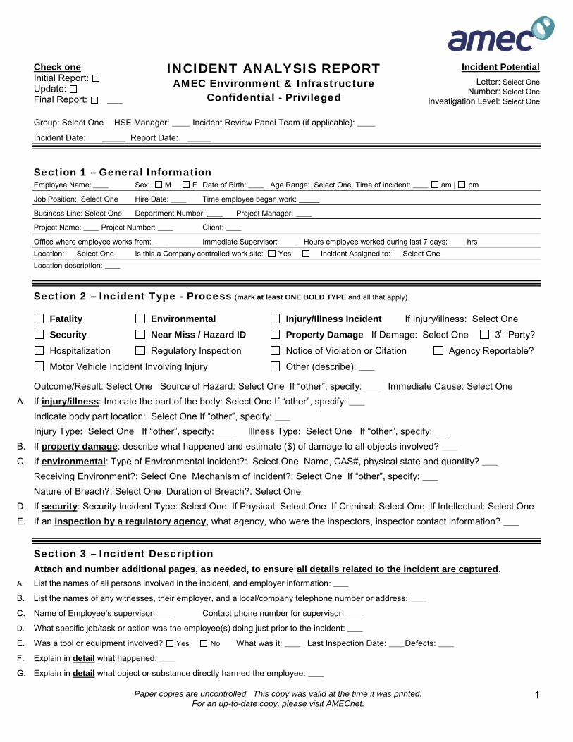
Paper copies are uncontrolled. This copy was valid at the time it was printed.For an up-to-date copy, please visit AMECnet.
1
Check oneInitial Report:Update:Final Report:
INCIDENT ANALYSIS REPORTAMEC Environment & Infrastructure
Confidential - Privileged
Incident PotentialLetter: Select One
Number: Select OneInvestigation Level: Select One
Group: Select One HSE Manager: Incident Review Panel Team (if applicable):
Incident Date: Report Date:
Section 1 – General InformationEmployee Name: Sex: M F Date of Birth: Age Range: Select One Time of incident: am | pm
Job Position: Select One Hire Date: Time employee began work:
Business Line: Select One Department Number: Project Manager:
Project Name: Project Number: Client:
Office where employee works from: Immediate Supervisor: Hours employee worked during last 7 days: hrsLocation: Select One Is this a Company controlled work site: Yes Incident Assigned to: Select OneLocation description:
Section 2 – Incident Type - Process (mark at least ONE BOLD TYPE and all that apply)
Fatality Environmental Injury/Illness Incident If Injury/illness: Select One
Security Near Miss / Hazard ID Property Damage If Damage: Select One 3rd Party?
Hospitalization Regulatory Inspection Notice of Violation or Citation Agency Reportable?
Motor Vehicle Incident Involving Injury Other (describe):
Outcome/Result: Select One Source of Hazard: Select One If “other”, specify: Immediate Cause: Select OneA. If injury/illness: Indicate the part of the body: Select One If “other”, specify:
Indicate body part location: Select One If “other”, specify:Injury Type: Select One If “other”, specify: Illness Type: Select One If “other”, specify:
B. If property damage: describe what happened and estimate ($) of damage to all objects involved?C. If environmental: Type of Environmental incident?: Select One Name, CAS#, physical state and quantity?
Receiving Environment?: Select One Mechanism of Incident?: Select One If “other”, specify:Nature of Breach?: Select One Duration of Breach?: Select One
D. If security: Security Incident Type: Select One If Physical: Select One If Criminal: Select One If Intellectual: Select OneE. If an inspection by a regulatory agency, what agency, who were the inspectors, inspector contact information?
Section 3 – Incident DescriptionAttach and number additional pages, as needed, to ensure all details related to the incident are captured.
A. List the names of all persons involved in the incident, and employer information:
B. List the names of any witnesses, their employer, and a local/company telephone number or address:
C. Name of Employee’s supervisor: Contact phone number for supervisor:
D. What specific job/task or action was the employee(s) doing just prior to the incident:
E. Was a tool or equipment involved? Yes No What was it: Last Inspection Date: Defects:
F. Explain in detail what happened:
G. Explain in detail what object or substance directly harmed the employee:
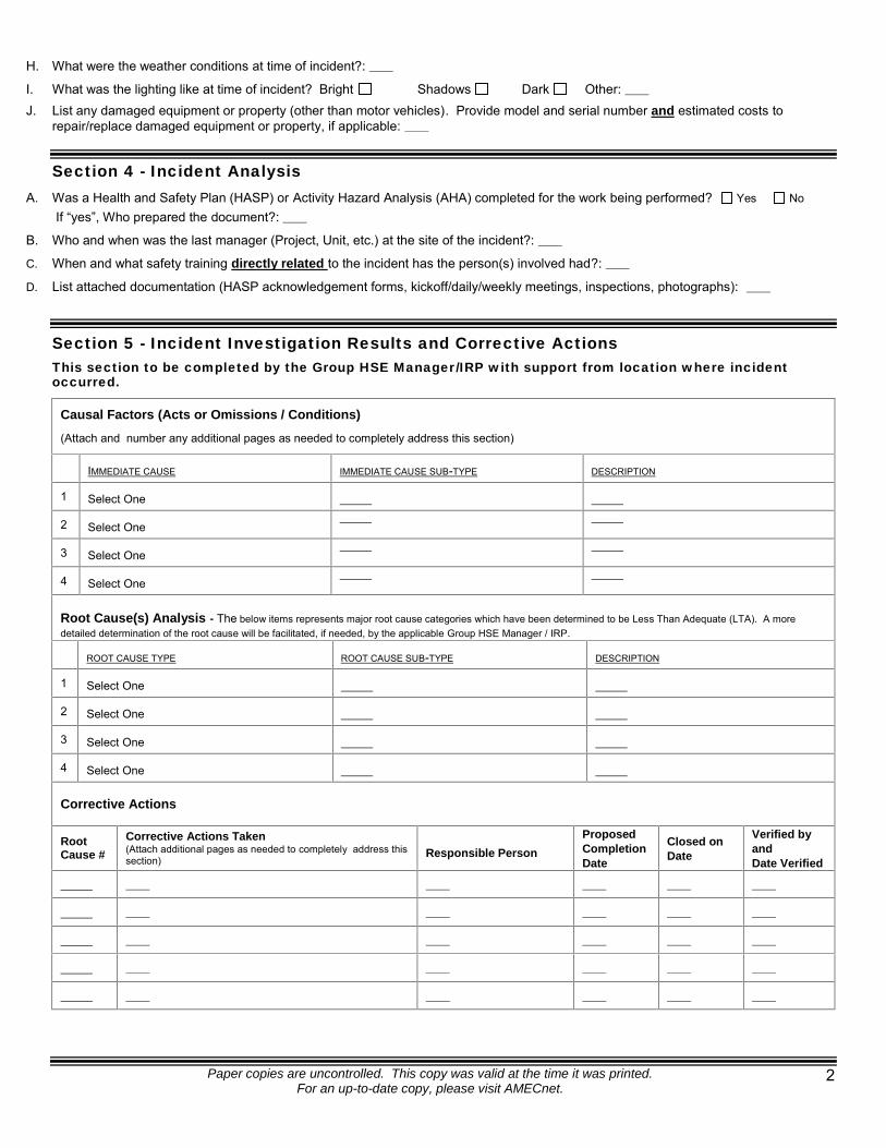
Paper copies are uncontrolled. This copy was valid at the time it was printed.For an up-to-date copy, please visit AMECnet.
2
H. What were the weather conditions at time of incident?:
I. What was the lighting like at time of incident? Bright Shadows Dark Other:J. List any damaged equipment or property (other than motor vehicles). Provide model and serial number and estimated costs to
repair/replace damaged equipment or property, if applicable:
Section 4 - Incident AnalysisA. Was a Health and Safety Plan (HASP) or Activity Hazard Analysis (AHA) completed for the work being performed? Yes No
If “yes”, Who prepared the document?:
B. Who and when was the last manager (Project, Unit, etc.) at the site of the incident?:
C. When and what safety training directly related to the incident has the person(s) involved had?:
D. List attached documentation (HASP acknowledgement forms, kickoff/daily/weekly meetings, inspections, photographs):
Section 5 - Incident Investigation Results and Corrective ActionsThis section to be completed by the Group HSE Manager/IRP with support from location where incidentoccurred.
Causal Factors (Acts or Omissions / Conditions)
(Attach and number any additional pages as needed to completely address this section)
IMMEDIATE CAUSE IMMEDIATE CAUSE SUB-TYPE DESCRIPTION
1 Select One
2 Select One
3 Select One
4 Select One
Root Cause(s) Analysis - The below items represents major root cause categories which have been determined to be Less Than Adequate (LTA). A moredetailed determination of the root cause will be facilitated, if needed, by the applicable Group HSE Manager / IRP.
ROOT CAUSE TYPE ROOT CAUSE SUB-TYPE DESCRIPTION
1 Select One
2 Select One
3 Select One
4 Select One
Corrective Actions
RootCause #
Corrective Actions Taken(Attach additional pages as needed to completely address thissection)
Responsible PersonProposedCompletionDate
Closed onDate
Verified byandDate Verified
Paper copies are uncontrolled. This copy was valid at the time it was printed.For an up-to-date copy, please visit AMECnet.
3
Section 6 - Notifications, Certification & ApprovalsCheck the appropriate boxes indicating the applicable reports have been made to the following applicable organizations:
Auto Insurance Carrier was called Group HSE Manager NotifiedWorkCare was called Post-incident Drug/Alcohol Testing Performed
Incident Report prepared by:
Employee (s): Date: Employee’s Supervisor: Date:
HSE Coordinator/Project/Unit Manager: Date: Group HSE Manager: Date:
ATTACHMENT 2
VIR FORM

© AMEC 2012 1
ATTACHMENT 2VEHICLE INCIDENT REPORT
Confidential - Privileged
Section 1 - General Information Date of Incident:Time incident occurred: am | pm | Illumination: Dark Dusk Light | Road Condition: Dry Wet Icy/snowWere police summoned to scene? Yes No Police Department and Location:Report #; Officer’s Name: Officer’s Badge Number:
Section 2 - Company Driver and Vehicle
Driver's name: D/L #: State:
Driver's home office address: Driver’s Phone #:
Company Vehicle #: Year: Model: License #: State:
Company car?: Yes No Personal Vehicle?: Yes No Rental Vehicle?: Yes No
If rental, rented from:
Passenger/Witness Name(s): Address: Telephone:
Passenger/Witness Name(s): Address: Telephone:
Damage to vehicle:
Was an employee injured?: Yes No If yes, please describe:
Injuries to others?: Yes No If yes, please describe:
Vehicle was being used for: Company business Yes No Personal business Yes No
Towed?: Yes No If yes, by whom?: To Where?:
Section 3 - Other Driver and Vehicle Information
Driver's Name: D/L # : State:
Current address: City: State:
Telephone: Work: Cell:
Registered Owner's Name: Address: City: State:
(verify registration document)
The Other Vehicle: Make: Model: Year: License #: State:
Insurance company name: Address: Phone #:
Policy No.: Contact Person: Phone #:
Passenger/Witness Name(s): Address: Telephone:
Passenger/Witness Name(s): Address: Telephone:
Damage: (Make note of pre-existing damage and take pictures if possible – you may attach additional pages if necessary):
Injuries to other driver/passengers:
Section 4 – Approvals (signatures required)
Form completed by (please print): Date: Office/Project Manager (please print): Date:
Signature: __________________________________________ Signature: __________________________________________

© AMEC 2012 2
Things to Do First In The Event Of a Motor Vehicle Incident
GENERAL INFORMATION1. Do not decide on your own whether a particular incident is “covered” by insurance. Should there be any doubt, it isalways preferable to report an occurrence, as this allows underwriters, the Risk Management Department and insuranceadjusters to determine if a covered loss has taken place.
2. Policy Conditions do require that all losses and occurrences, which may result in a claimbe promptly reported.
3. Do not admit liability or offer your opinion of liability to anyone.
4. Complete this IAR/VIR form promptly and forward with all applicable supporting documentation. It is essential bothdivision and location information be provided.
5. For automobile collisions within the United States, please indicate on the IAR form that you have contacted Zurich at:Zurich Insurance Company
1-800-987-3373 or1-877-928-4531
24 hours a day, 7 days a week
6. For automobile collisions within Canada, please indicate on the IAR form that you have contacted Zurich at:Crawford Adjusters Canada
Claims Alert1-888-218-2346
24 hours a day, 7 days a week
The more details you have the better but, don’t delay reporting if you don’t have all of the information - that may beobtained later. A Zurich trained operator will answer your call and ask for all relevant information regarding the incident.The initial information required includes: Your division, Office location and division contact name – advise that you are an AMEC Company Name, drivers license and phone number of the driver involved in the loss Description of the vehicle which he/she was driving (i.e., year, make, model, license plate number, serial number) Date, time and location of incident Passenger information (if applicable) Third party information (i.e., name, phone number, address, vehicle information, insurance information) If any injuries occurred (if applicable) Police information Witness information (if applicable)
Call 911 if there are serious injuries!If you are injured or think you were injured, contact your supervisor and call WorkCare at 888-449-7787. Yoursupervisor will notify your HSE Coordinator and your Group HSE Manager. For additional instructions on what to do, goto AMEC’s HSE website at:
http://ee.amecnet.com/she/sheweb/incident_reporting.htm
1. Call for an officer if the incident occurred on public property (streets, highways or roads). Disputes often arisebetween the parties involved as to who was at fault; therefore, a police report is important. If an officer is unable to attendthe scene of the collision, a counter police report may be filed at most stations. Insurance companies rely on policereports to determine liability.2. Complete the Incident Investigation Report and the Vehicle Incident Report forms. It is important that both theseforms are completed in detail. Include a diagram of the incident on the provided sheet. Incomplete information may leadto delays in processing associated claims and in helping to prevent this type of incident from occurring again.3. Give only information that is required by the authorities or as directed by AMEC contractual requirements.4. Sign only those statements required by the authorities or as directed by AMEC contractual requirements. Do notsign away your or the company's rights.

© AMEC 2012 3
Vehicle Incident DiagramThis or a similar diagram must be completed with all VIRs
ATTACHMENT 3
1. Number each vehicle and show directions2. Use a solid line to show path before incident and use a dotted line to show path after incient
3. Show pedestrian/non-motorist by:
5. Indicate north by arrow as:6. Show street or highway names or numbers7. Show signs, signals, warning and traffic controls.
Prepared by: Date:
4. Show railroad by:
Indicate Northby Arrow
Vehicle Crash Diagram
(after)(before)
Instructions:1 2
1 1

ATTACHMENT 3
GDR FORM
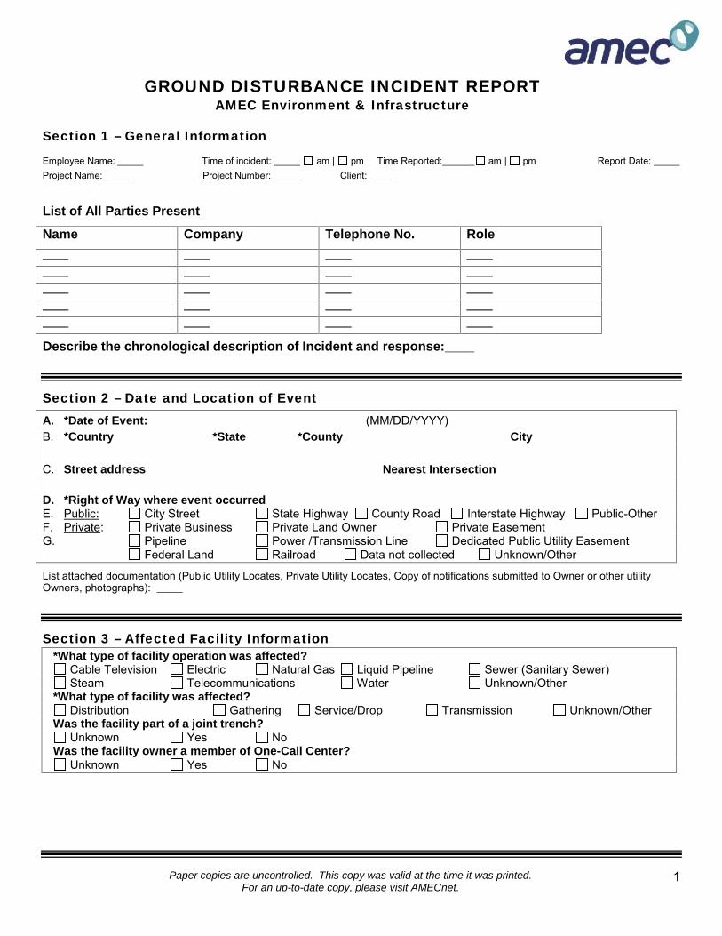
Paper copies are uncontrolled. This copy was valid at the time it was printed.For an up-to-date copy, please visit AMECnet.
1
GROUND DISTURBANCE INCIDENT REPORTAMEC Environment & Infrastructure
Section 1 – General Information
Employee Name: Time of incident: am | pm Time Reported: am | pm Report Date:Project Name: Project Number: Client:
List of All Parties Present
Name Company Telephone No. Role
Describe the chronological description of Incident and response:
Section 2 – Date and Location of EventA. *Date of Event: (MM/DD/YYYY)B. *Country *State *County City
C. Street address Nearest Intersection
D. *Right of Way where event occurredE. Public: City Street State Highway County Road Interstate Highway Public-OtherF. Private: Private Business Private Land Owner Private EasementG. Pipeline Power /Transmission Line Dedicated Public Utility Easement
Federal Land Railroad Data not collected Unknown/Other
List attached documentation (Public Utility Locates, Private Utility Locates, Copy of notifications submitted to Owner or other utilityOwners, photographs):
Section 3 – Affected Facility Information*What type of facility operation was affected?
Cable Television Electric Natural Gas Liquid Pipeline Sewer (Sanitary Sewer)Steam Telecommunications Water Unknown/Other
*What type of facility was affected?Distribution Gathering Service/Drop Transmission Unknown/Other
Was the facility part of a joint trench?Unknown Yes No
Was the facility owner a member of One-Call Center?Unknown Yes No
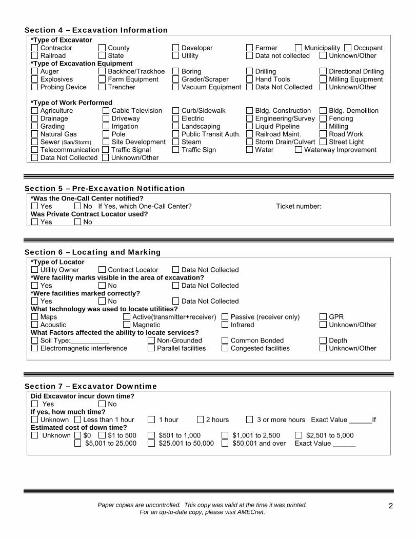
Paper copies are uncontrolled. This copy was valid at the time it was printed.For an up-to-date copy, please visit AMECnet.
2
Section 4 – Excavation Information*Type of Excavator
Contractor County Developer Farmer Municipality OccupantRailroad State Utility Data not collected Unknown/Other
*Type of Excavation EquipmentAuger Backhoe/Trackhoe Boring Drilling Directional DrillingExplosives Farm Equipment Grader/Scraper Hand Tools Milling EquipmentProbing Device Trencher Vacuum Equipment Data Not Collected Unknown/Other
*Type of Work PerformedAgriculture Cable Television Curb/Sidewalk Bldg. Construction Bldg. DemolitionDrainage Driveway Electric Engineering/Survey FencingGrading Irrigation Landscaping Liquid Pipeline MillingNatural Gas Pole Public Transit Auth. Railroad Maint. Road WorkSewer (San/Storm) Site Development Steam Storm Drain/Culvert Street LightTelecommunication Traffic Signal Traffic Sign Water Waterway ImprovementData Not Collected Unknown/Other
Section 5 – Pre-Excavation Notification*Was the One-Call Center notified?
Yes No If Yes, which One-Call Center? Ticket number:Was Private Contract Locator used?
Yes No
Section 6 – Locating and Marking*Type of Locator
Utility Owner Contract Locator Data Not Collected*Were facility marks visible in the area of excavation?
Yes No Data Not Collected*Were facilities marked correctly?
Yes No Data Not CollectedWhat technology was used to locate utilities?
Maps Active(transmitter+receiver) Passive (receiver only) GPRAcoustic Magnetic Infrared Unknown/Other
What Factors affected the ability to locate services?Soil Type:__________ Non-Grounded Common Bonded DepthElectromagnetic interference Parallel facilities Congested facilities Unknown/Other
Section 7 – Excavator DowntimeDid Excavator incur down time?
Yes NoIf yes, how much time?
Unknown Less than 1 hour 1 hour 2 hours 3 or more hours Exact Value ______IfEstimated cost of down time?
Unknown $0 $1 to 500 $501 to 1,000 $1,001 to 2,500 $2,501 to 5,000$5,001 to 25,000 $25,001 to 50,000 $50,001 and over Exact Value ______
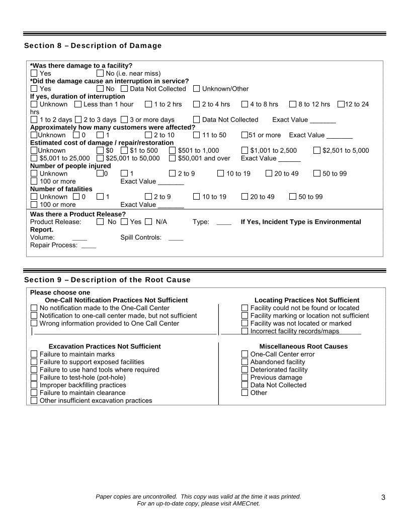
Paper copies are uncontrolled. This copy was valid at the time it was printed.For an up-to-date copy, please visit AMECnet.
3
Section 8 – Description of Damage
*Was there damage to a facility?Yes No (i.e. near miss)
*Did the damage cause an interruption in service?Yes No Data Not Collected Unknown/Other
If yes, duration of interruptionUnknown Less than 1 hour 1 to 2 hrs 2 to 4 hrs 4 to 8 hrs 8 to 12 hrs 12 to 24
hrs1 to 2 days 2 to 3 days 3 or more days Data Not Collected Exact Value _______
Approximately how many customers were affected?Unknown 0 1 2 to 10 11 to 50 51 or more Exact Value _______
Estimated cost of damage / repair/restorationUnknown $0 $1 to 500 $501 to 1,000 $1,001 to 2,500 $2,501 to 5,000$5,001 to 25,000 $25,001 to 50,000 $50,001 and over Exact Value ______
Number of people injuredUnknown 0 1 2 to 9 10 to 19 20 to 49 50 to 99100 or more Exact Value _______
Number of fatalitiesUnknown 0 1 2 to 9 10 to 19 20 to 49 50 to 99100 or more Exact Value _______
Was there a Product Release?Product Release: No Yes N/A Type: If Yes, Incident Type is EnvironmentalReport.Volume: Spill Controls:Repair Process:
Section 9 – Description of the Root CausePlease choose one
One-Call Notification Practices Not Sufficient Locating Practices Not SufficientNo notification made to the One-Call Center │ Facility could not be found or locatedNotification to one-call center made, but not sufficient │ Facility marking or location not sufficientWrong information provided to One Call Center │ Facility was not located or marked
│ │ Incorrect facility records/maps
Excavation Practices Not Sufficient │ Miscellaneous Root CausesFailure to maintain marks │ One-Call Center errorFailure to support exposed facilities │ Abandoned facilityFailure to use hand tools where required │ Deteriorated facilityFailure to test-hole (pot-hole) │ Previous damageImproper backfilling practices │ Data Not CollectedFailure to maintain clearance │ OtherOther insufficient excavation practices │

Paper copies are uncontrolled. This copy was valid at the time it was printed.For an up-to-date copy, please visit AMECnet.
4
Section 10 - Notifications, Certification & ApprovalsCheck the appropriate boxes indicating the applicable reports have been made to the following applicable organizations:
One Call was called Spills Reporting Agency NotifiedEmergency Responders (Fire) was called Post-incident Drug/Alcohol Testing Performed
List of All Agencies Contacted
Name/Agency Phone # Date Time
Incident Report prepared by:
Employee (s): Date: Employee’s Supervisor: Date:
HSE Coordinator/Project/Unit Manager: Date: Group HSE Manager: Date:
ATTACHMENT 4
Job Hazard Analyses (JHAs)
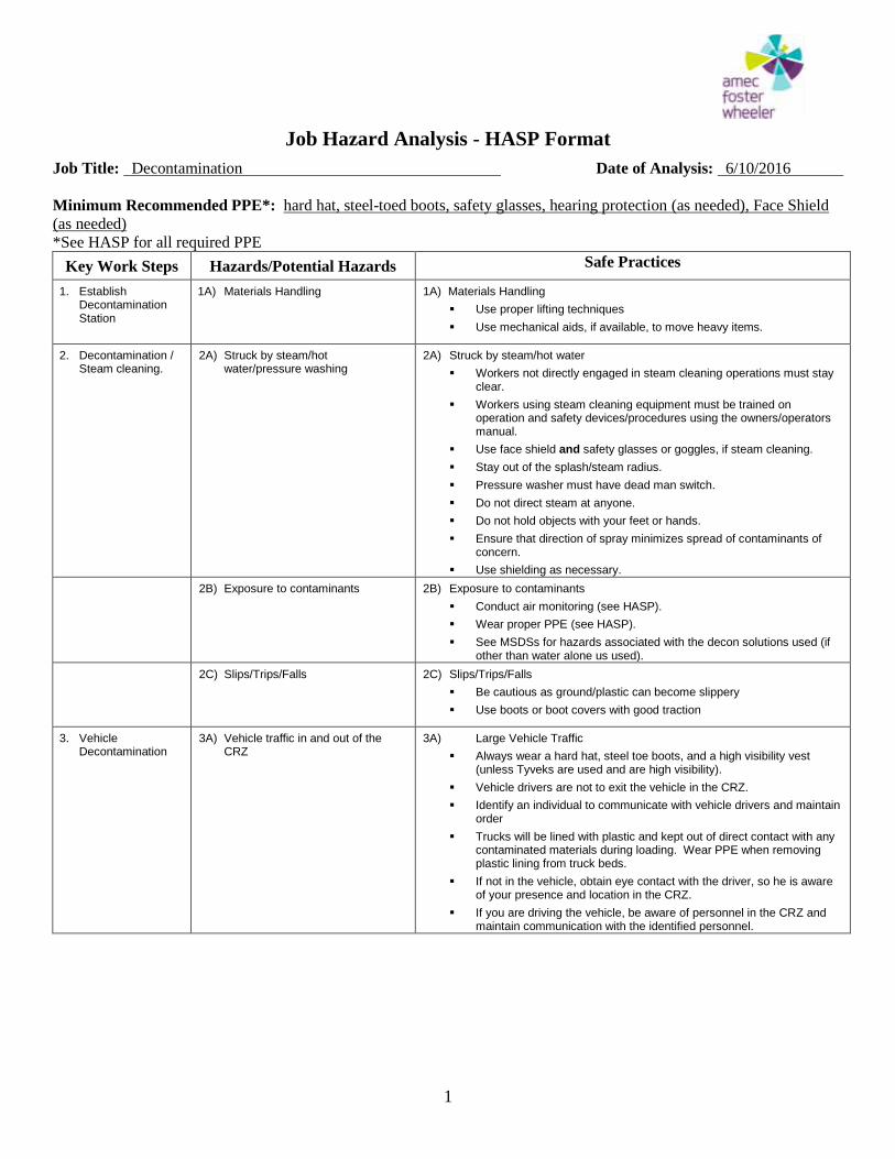
Job Hazard Analysis - HASP Format
Job Title: Decontamination Date of Analysis: 6/10/2016
1
Minimum Recommended PPE*: hard hat, steel-toed boots, safety glasses, hearing protection (as needed), Face Shield
(as needed)
*See HASP for all required PPE
Key Work Steps Hazards/Potential Hazards Safe Practices
1. Establish Decontamination Station
1A) Materials Handling 1A) Materials Handling
Use proper lifting techniques
Use mechanical aids, if available, to move heavy items.
2. Decontamination / Steam cleaning.
2A) Struck by steam/hot water/pressure washing
2A) Struck by steam/hot water
Workers not directly engaged in steam cleaning operations must stay clear.
Workers using steam cleaning equipment must be trained on operation and safety devices/procedures using the owners/operators manual.
Use face shield and safety glasses or goggles, if steam cleaning.
Stay out of the splash/steam radius.
Pressure washer must have dead man switch.
Do not direct steam at anyone.
Do not hold objects with your feet or hands.
Ensure that direction of spray minimizes spread of contaminants of concern.
Use shielding as necessary.
2B) Exposure to contaminants 2B) Exposure to contaminants
Conduct air monitoring (see HASP).
Wear proper PPE (see HASP).
See MSDSs for hazards associated with the decon solutions used (if other than water alone us used).
2C) Slips/Trips/Falls 2C) Slips/Trips/Falls
Be cautious as ground/plastic can become slippery
Use boots or boot covers with good traction
3. Vehicle Decontamination
3A) Vehicle traffic in and out of the CRZ
3A) Large Vehicle Traffic
Always wear a hard hat, steel toe boots, and a high visibility vest (unless Tyveks are used and are high visibility).
Vehicle drivers are not to exit the vehicle in the CRZ.
Identify an individual to communicate with vehicle drivers and maintain order
Trucks will be lined with plastic and kept out of direct contact with any contaminated materials during loading. Wear PPE when removing plastic lining from truck beds.
If not in the vehicle, obtain eye contact with the driver, so he is aware of your presence and location in the CRZ.
If you are driving the vehicle, be aware of personnel in the CRZ and maintain communication with the identified personnel.
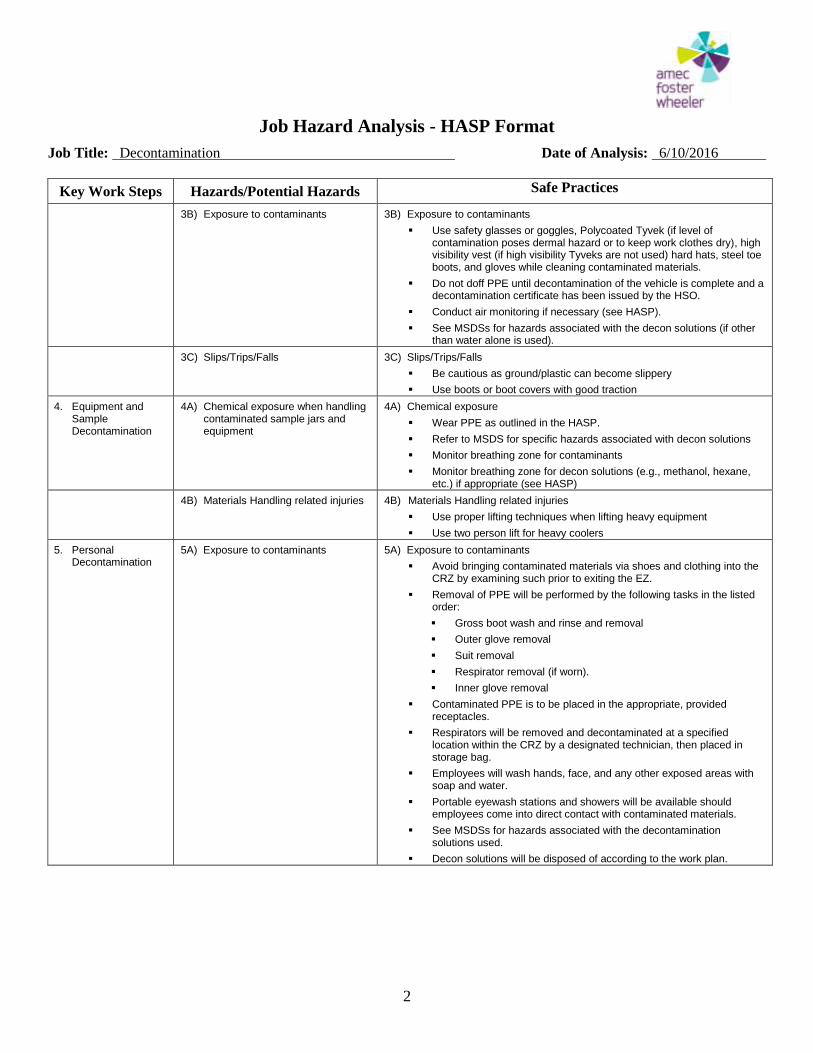
Job Hazard Analysis - HASP Format
Job Title: Decontamination Date of Analysis: 6/10/2016
2
Key Work Steps Hazards/Potential Hazards Safe Practices
3B) Exposure to contaminants 3B) Exposure to contaminants
Use safety glasses or goggles, Polycoated Tyvek (if level of contamination poses dermal hazard or to keep work clothes dry), high visibility vest (if high visibility Tyveks are not used) hard hats, steel toe boots, and gloves while cleaning contaminated materials.
Do not doff PPE until decontamination of the vehicle is complete and a decontamination certificate has been issued by the HSO.
Conduct air monitoring if necessary (see HASP).
See MSDSs for hazards associated with the decon solutions (if other than water alone is used).
3C) Slips/Trips/Falls 3C) Slips/Trips/Falls
Be cautious as ground/plastic can become slippery
Use boots or boot covers with good traction
4. Equipment and Sample Decontamination
4A) Chemical exposure when handling contaminated sample jars and equipment
4A) Chemical exposure
Wear PPE as outlined in the HASP.
Refer to MSDS for specific hazards associated with decon solutions
Monitor breathing zone for contaminants
Monitor breathing zone for decon solutions (e.g., methanol, hexane, etc.) if appropriate (see HASP)
4B) Materials Handling related injuries 4B) Materials Handling related injuries
Use proper lifting techniques when lifting heavy equipment
Use two person lift for heavy coolers
5. Personal Decontamination
5A) Exposure to contaminants 5A) Exposure to contaminants
Avoid bringing contaminated materials via shoes and clothing into the CRZ by examining such prior to exiting the EZ.
Removal of PPE will be performed by the following tasks in the listed order:
Gross boot wash and rinse and removal
Outer glove removal
Suit removal
Respirator removal (if worn).
Inner glove removal
Contaminated PPE is to be placed in the appropriate, provided receptacles.
Respirators will be removed and decontaminated at a specified location within the CRZ by a designated technician, then placed in storage bag.
Employees will wash hands, face, and any other exposed areas with soap and water.
Portable eyewash stations and showers will be available should employees come into direct contact with contaminated materials.
See MSDSs for hazards associated with the decontamination solutions used.
Decon solutions will be disposed of according to the work plan.
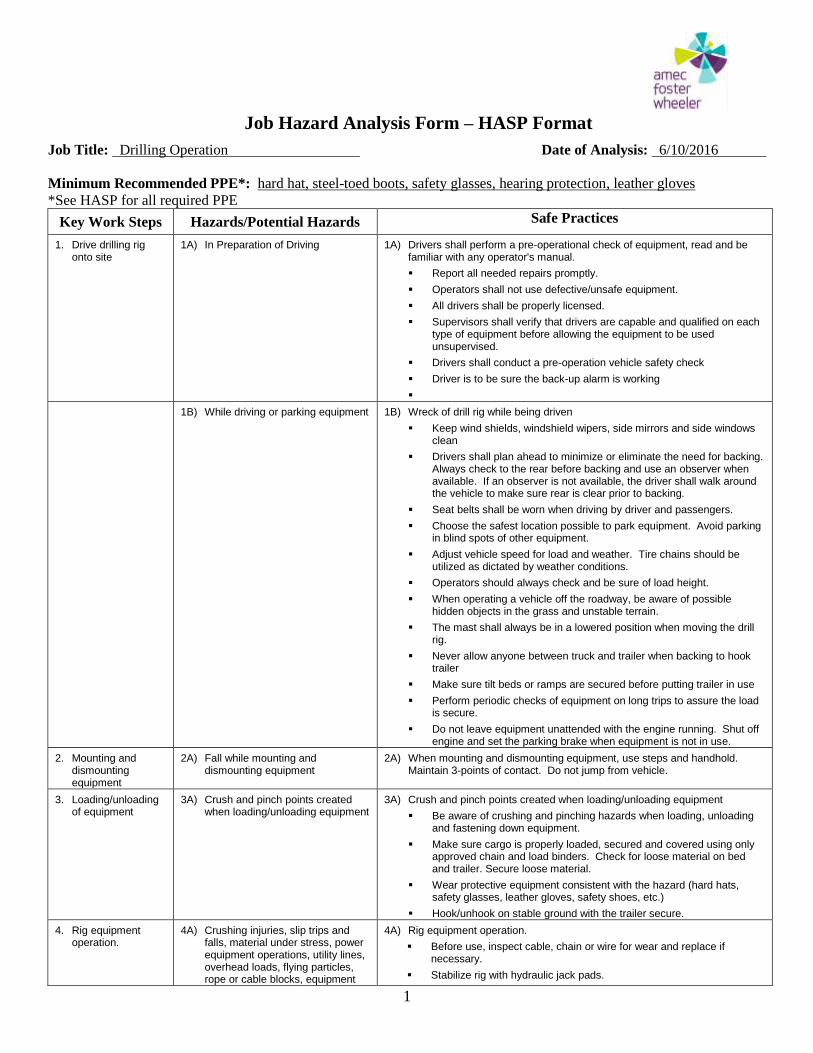
Job Hazard Analysis Form – HASP Format
Job Title: Drilling Operation Date of Analysis: 6/10/2016
1
Minimum Recommended PPE*: hard hat, steel-toed boots, safety glasses, hearing protection, leather gloves
*See HASP for all required PPE
Key Work Steps Hazards/Potential Hazards Safe Practices
1. Drive drilling rig onto site
1A) In Preparation of Driving 1A) Drivers shall perform a pre-operational check of equipment, read and be familiar with any operator's manual.
Report all needed repairs promptly.
Operators shall not use defective/unsafe equipment.
All drivers shall be properly licensed.
Supervisors shall verify that drivers are capable and qualified on each type of equipment before allowing the equipment to be used unsupervised.
Drivers shall conduct a pre-operation vehicle safety check
Driver is to be sure the back-up alarm is working
1B) While driving or parking equipment 1B) Wreck of drill rig while being driven
Keep wind shields, windshield wipers, side mirrors and side windows clean
Drivers shall plan ahead to minimize or eliminate the need for backing. Always check to the rear before backing and use an observer when available. If an observer is not available, the driver shall walk around the vehicle to make sure rear is clear prior to backing.
Seat belts shall be worn when driving by driver and passengers.
Choose the safest location possible to park equipment. Avoid parking in blind spots of other equipment.
Adjust vehicle speed for load and weather. Tire chains should be utilized as dictated by weather conditions.
Operators should always check and be sure of load height.
When operating a vehicle off the roadway, be aware of possible hidden objects in the grass and unstable terrain.
The mast shall always be in a lowered position when moving the drill rig.
Never allow anyone between truck and trailer when backing to hook trailer
Make sure tilt beds or ramps are secured before putting trailer in use
Perform periodic checks of equipment on long trips to assure the load is secure.
Do not leave equipment unattended with the engine running. Shut off engine and set the parking brake when equipment is not in use.
2. Mounting and dismounting equipment
2A) Fall while mounting and dismounting equipment
2A) When mounting and dismounting equipment, use steps and handhold. Maintain 3-points of contact. Do not jump from vehicle.
3. Loading/unloading of equipment
3A) Crush and pinch points created when loading/unloading equipment
3A) Crush and pinch points created when loading/unloading equipment
Be aware of crushing and pinching hazards when loading, unloading and fastening down equipment.
Make sure cargo is properly loaded, secured and covered using only approved chain and load binders. Check for loose material on bed and trailer. Secure loose material.
Wear protective equipment consistent with the hazard (hard hats, safety glasses, leather gloves, safety shoes, etc.)
Hook/unhook on stable ground with the trailer secure.
4. Rig equipment operation.
4A) Crushing injuries, slip trips and falls, material under stress, power equipment operations, utility lines, overhead loads, flying particles, rope or cable blocks, equipment
4A) Rig equipment operation.
Before use, inspect cable, chain or wire for wear and replace if necessary.
Stabilize rig with hydraulic jack pads.
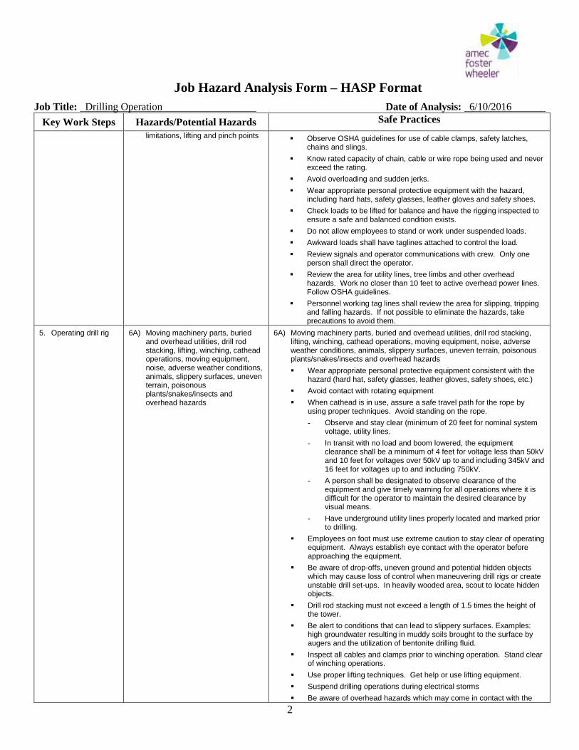
Job Hazard Analysis Form – HASP Format
Job Title: Drilling Operation Date of Analysis: 6/10/2016
2
Key Work Steps Hazards/Potential Hazards Safe Practices
limitations, lifting and pinch points Observe OSHA guidelines for use of cable clamps, safety latches,
chains and slings.
Know rated capacity of chain, cable or wire rope being used and never exceed the rating.
Avoid overloading and sudden jerks.
Wear appropriate personal protective equipment with the hazard, including hard hats, safety glasses, leather gloves and safety shoes.
Check loads to be lifted for balance and have the rigging inspected to ensure a safe and balanced condition exists.
Do not allow employees to stand or work under suspended loads.
Awkward loads shall have taglines attached to control the load.
Review signals and operator communications with crew. Only one person shall direct the operator.
Review the area for utility lines, tree limbs and other overhead hazards. Work no closer than 10 feet to active overhead power lines. Follow OSHA guidelines.
Personnel working tag lines shall review the area for slipping, tripping and falling hazards. If not possible to eliminate the hazards, take precautions to avoid them.
5. Operating drill rig 6A) Moving machinery parts, buried and overhead utilities, drill rod stacking, lifting, winching, cathead operations, moving equipment, noise, adverse weather conditions, animals, slippery surfaces, uneven terrain, poisonous plants/snakes/insects and overhead hazards
6A) Moving machinery parts, buried and overhead utilities, drill rod stacking, lifting, winching, cathead operations, moving equipment, noise, adverse weather conditions, animals, slippery surfaces, uneven terrain, poisonous plants/snakes/insects and overhead hazards
Wear appropriate personal protective equipment consistent with the hazard (hard hat, safety glasses, leather gloves, safety shoes, etc.)
Avoid contact with rotating equipment
When cathead is in use, assure a safe travel path for the rope by using proper techniques. Avoid standing on the rope.
- Observe and stay clear (minimum of 20 feet for nominal system voltage, utility lines.
- In transit with no load and boom lowered, the equipment clearance shall be a minimum of 4 feet for voltage less than 50kV and 10 feet for voltages over 50kV up to and including 345kV and 16 feet for voltages up to and including 750kV.
- A person shall be designated to observe clearance of the equipment and give timely warning for all operations where it is difficult for the operator to maintain the desired clearance by visual means.
- Have underground utility lines properly located and marked prior to drilling.
Employees on foot must use extreme caution to stay clear of operating equipment. Always establish eye contact with the operator before approaching the equipment.
Be aware of drop-offs, uneven ground and potential hidden objects which may cause loss of control when maneuvering drill rigs or create unstable drill set-ups. In heavily wooded area, scout to locate hidden objects.
Drill rod stacking must not exceed a length of 1.5 times the height of the tower.
Be alert to conditions that can lead to slippery surfaces. Examples: high groundwater resulting in muddy soils brought to the surface by augers and the utilization of bentonite drilling fluid.
Inspect all cables and clamps prior to winching operation. Stand clear of winching operations.
Use proper lifting techniques. Get help or use lifting equipment.
Suspend drilling operations during electrical storms
Be aware of overhead hazards which may come in contact with the

Job Hazard Analysis Form – HASP Format
Job Title: Drilling Operation Date of Analysis: 6/10/2016
3
Key Work Steps Hazards/Potential Hazards Safe Practices
drill rig, when moving or setting up equipment.
Complete a daily operations checklist to ensure that equipment is working properly. Make special note of emergency kill switches.
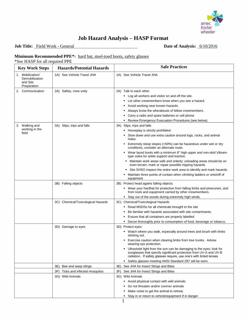
Job Hazard Analysis – HASP Format
Job Title: Field Work - General Date of Analysis: 6/10/2016
1
Minimum Recommended PPE*: hard hat, steel-toed boots, safety glasses
*See HASP for all required PPE
Key Work Steps Hazards/Potential Hazards Safe Practices
1. Mobilization/ Demobilization and Site Preparation
1A) See Vehicle Travel JHA 1A) See Vehicle Travel JHA.
2. Communication 2A) Safety, crew unity 2A) Talk to each other.
Log all workers and visitor on and off the site.
Let other crewmembers know when you see a hazard.
Avoid working near known hazards.
Always know the wherabouts of fellow crewmembers.
Carry a radio and spare batteries or cell phone
Review Emergency Evacuation Procedures (see below).
3. Walking and working in the field
3A) Slips, trips and falls 3A) Slips, trips and falls
Horseplay is strictly prohibited
Slow down and use extra caution around logs, rocks, and animal holes.
Extremely steep slopes (>50%) can be hazardous under wet or dry conditions; consider an alternate route.
Wear laced boots with a minimum 8" high upper and non-skid Vibram-type soles for ankle support and traction.
Maintain work areas safe and orderly; unloading areas should be on even terrain; mark or repair possible tripping hazards.
Site SHSO inspect the entire work area to identify and mark hazards.
Maintain three points of contact when climbing ladders or onto/off of equipment
3B) Falling objects 3B) Protect head agains falling objects.
Wear your hardhat for protection from falling limbs and pinecones, and from tools and equipment carried by other crewmembers.
Stay out of the woods during extremely high winds.
3C) Chemical/Toxicological Hazards 3C) Chemical/Toxicological Hazards
Read MSDSs for all chemicals brought to the site
Be familiar with hazards associated with site contaminants.
Ensure that all containers are properly labelled
Decon thoroughly prior to consumption of food, beverage or tobacco.
3D) Damage to eyes 3D) Protect eyes:
Watch where you walk, ecpecially around trees and brush with limbs sticking out.
Exercise caution when clearing limbs from tree trunks. Advise wearing eye protection.
Ultraviolet light from the sun can be damaging to the eyes; look for sunglasses that specify significant protection from UV-A and UV-B radiation. If safety glasses require, use one’s with tinted lenses
Safety glasses meeting ANSI Standard Z87 will be worn.
3E) Bee and wasp stings 3E) See JHA for Insect Stings and Bites
3F) Ticks and infected mosquitos 3F) See JHA for Insect Stings and Bites
3G) Wild Animals 3G) Wild Animals
Avoid phyisical contact with wild animals
Do not threaten and/or conrner animals
Make noise to get the animal to retreat.
Stay in or return to vehicle/equipment if in danger
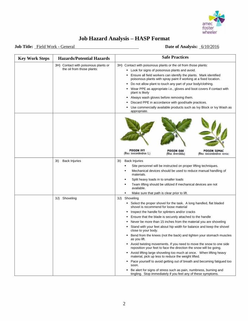
Job Hazard Analysis – HASP Format
Job Title: Field Work - General Date of Analysis: 6/10/2016
2
Key Work Steps Hazards/Potential Hazards Safe Practices
3H) Contact with poisonous plants or the oil from those plants:
3H) Contact with poisonous plants or the oil from those plants:
Look for signs of poisonous plants and avoid.
Ensure all field workers can identify the plants. Mark identified poisonous plants with spray paint if working at a fixed location.
Do not allow plant to touch any part of your body/clothing.
Wear PPE as appropriate i.e., gloves and boot covers if contact with plant is likely
Always wash gloves before removing them.
Discard PPE in accordance with good/safe practices.
Use commercially available products such as Ivy Block or Ivy Wash as appropriate.
3I) Back Injuries 3I) Back Injuries
Site personnel will be instructed on proper lifting techniques.
Mechanical devices should be used to reduce manual handling of materials.
Split heavy loads in to smaller loads
Team lifting should be utilized if mechanical devices are not available.
Make sure that path is clear prior to lift.
3J) Shoveling 3J) Shoveling
Select the proper shovel for the task. A long handled, flat bladed shovel is recommend for loose material
Inspect the handle for splinters and/or cracks
Ensure that the blade is securely attached to the handle
Never be more than 15 inches from the material you are shoveling
Stand with your feet about hip width for balance and keep the shovel close to your body.
Bend from the knees (not the back) and tighten your stomach muscles as you lift.
Avoid twisting movements. If you need to move the snow to one side reposition your feet to face the direction the snow will be going.
Avoid lifting large shoveling too much at once. When lifting heavy material, pick up less to reduce the weight lifted.
Pace yourself to avoid getting out of breath and becoming fatigued too soon.
Be alert for signs of stress such as pain, numbness, burning and tingling. Stop immediately if you feel any of these symptoms.
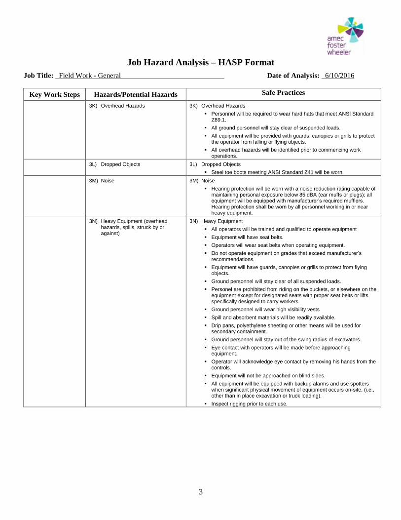
Job Hazard Analysis – HASP Format
Job Title: Field Work - General Date of Analysis: 6/10/2016
3
Key Work Steps Hazards/Potential Hazards Safe Practices
3K) Overhead Hazards 3K) Overhead Hazards
Personnel will be required to wear hard hats that meet ANSI Standard Z89.1.
All ground personnel will stay clear of suspended loads.
All equipment will be provided with guards, canopies or grills to protect the operator from falling or flying objects.
All overhead hazards will be identified prior to commencing work operations.
3L) Dropped Objects 3L) Dropped Objects
Steel toe boots meeting ANSI Standard Z41 will be worn.
3M) Noise 3M) Noise
Hearing protection will be worn with a noise reduction rating capable of maintaining personal exposure below 85 dBA (ear muffs or plugs); all equipment will be equipped with manufacturer’s required mufflers. Hearing protection shall be worn by all personnel working in or near heavy equipment.
3N) Heavy Equipment (overhead hazards, spills, struck by or against)
3N) Heavy Equipment
All operators will be trained and qualified to operate equipment
Equipment will have seat belts.
Operators will wear seat belts when operating equipment.
Do not operate equipment on grades that exceed manufacturer’s recommendations.
Equipment will have guards, canopies or grills to protect from flying objects.
Ground personnel will stay clear of all suspended loads.
Personel are prohibited from riding on the buckets, or elsewhere on the equipment except for designated seats with proper seat belts or lifts specifically designed to carry workers.
Ground personnel will wear high visibility vests
Spill and absorbent materials will be readily available.
Drip pans, polyethylene sheeting or other means will be used for secondary containment.
Ground personnel will stay out of the swing radius of excavators.
Eye contact with operators will be made before approaching equipment.
Operator will acknowledge eye contact by removing his hands from the controls.
Equipment will not be approached on blind sides.
All equipment will be equipped with backup alarms and use spotters when significant physical movement of equipment occurs on-site, (i.e., other than in place excavation or truck loading).
Inspect rigging prior to each use.
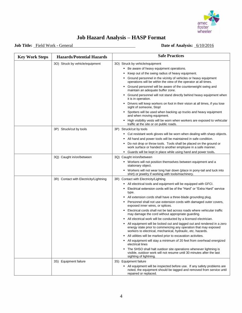
Job Hazard Analysis – HASP Format
Job Title: Field Work - General Date of Analysis: 6/10/2016
4
Key Work Steps Hazards/Potential Hazards Safe Practices
3O) Struck by vehicle/equipment 3O) Struck by vehicle/equipment
Be aware of heavy equipment operations.
Keep out of the swing radius of heavy equipment.
Ground personnel in the vicinity of vehicles or heavy equipment operations will be within the view of the operator at all times.
Ground personnel will be aware of the counterweight swing and maintain an adequate buffer zone.
Ground personnel will not stand directly behind heavy equipment when it is in operation.
Drivers will keep workers on foot in their vision at all times, if you lose sight of someone, Stop!
Spotters will be used when backing up trucks and heavy equipment and when moving equipment.
High visibility vests will be worn when workers are exposed to vehicular traffic at the site or on public roads.
3P) Struck/cut by tools 3P) Struck/cut by tools
Cut resistant work gloves will be worn when dealing with sharp objects.
All hand and power tools will be maintained in safe condition.
Do not drop or throw tools. Tools shall be placed on the ground or work surface or handed to another employee in a safe manner.
Guards will be kept in place while using hand and power tools.
3Q) Caught in/on/between 3Q) Caught in/on/between
Workers will not position themselves between equipment and a stationary object.
Workers will not wear long hair down (place in pony-tail and tuck into shirt) or jewelry if working with tools/machinery.
3R) Contact with Electricity/Lightning 3R) Contact with Electricity/Lighting
All electrical tools and equipment will be equipped with GFCI.
Electrical extension cords will be of the “Hard” or “Extra Hard” service type.
All extension cords shall have a three-blade grounding plug.
Personnel shall not use extension cords with damaged outer covers, exposed inner wires, or splices.
Electrical cords shall not be laid across roads where vehicular traffic may damage the cord without appropriate guarding.
All electrical work will be conducted by a licensed electrician.
All equipment will be locked out and tagged out and rendered in a zero energy state prior to commencing any operation that may exposed workers to electrical, mechanical, hydraulic, etc. hazards.
All utilities will be marked prior to excavation activities.
All equipment will stay a minimum of 20 feet from overhead energized electrical lines
The SHSO shall halt outdoor site operations whenever lightning is visible, outdoor work will not resume until 30 minutes after the last sighting of lightning.
3S) Equipment failure 3S) Equipment failure
All equipment will be inspected before use. If any safety problems are noted, the equipment should be tagged and removed from service until repaired or replaced.
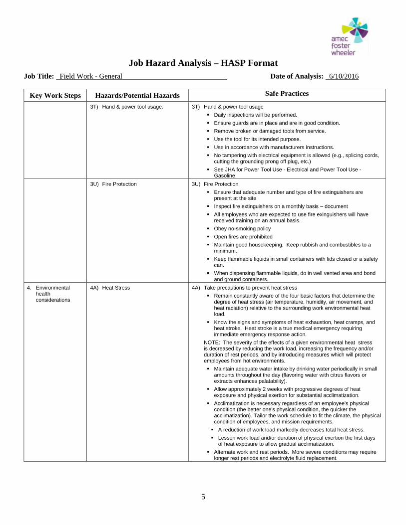
Job Hazard Analysis – HASP Format
Job Title: Field Work - General Date of Analysis: 6/10/2016
5
Key Work Steps Hazards/Potential Hazards Safe Practices
3T) Hand & power tool usage. 3T) Hand & power tool usage
Daily inspections will be performed.
Ensure guards are in place and are in good condition.
Remove broken or damaged tools from service.
Use the tool for its intended purpose.
Use in accordance with manufacturers instructions.
No tampering with electrical equipment is allowed (e.g., splicing cords, cutting the grounding prong off plug, etc.)
See JHA for Power Tool Use - Electrical and Power Tool Use - Gasoline
3U) Fire Protection 3U) Fire Protection
Ensure that adequate number and type of fire extinguishers are present at the site
Inspect fire extinguishers on a monthly basis – document
All employees who are expected to use fire exinguishers will have received training on an annual basis.
Obey no-smoking policy
Open fires are prohibited
Maintain good housekeeping. Keep rubbish and combustibles to a minimum.
Keep flammable liquids in small containers with lids closed or a safety can.
When dispensing flammable liquids, do in well vented area and bond and ground containers.
4. Environmental health considerations
4A) Heat Stress 4A) Take precautions to prevent heat stress
Remain constantly aware of the four basic factors that determine the degree of heat stress (air temperature, humidity, air movement, and heat radiation) relative to the surrounding work environmental heat load.
Know the signs and symptoms of heat exhaustion, heat cramps, and heat stroke. Heat stroke is a true medical emergency requiring immediate emergency response action.
NOTE: The severity of the effects of a given environmental heat stress is decreased by reducing the work load, increasing the frequency and/or duration of rest periods, and by introducing measures which will protect employees from hot environments.
Maintain adequate water intake by drinking water periodically in small amounts throughout the day (flavoring water with citrus flavors or extracts enhances palatability).
Allow approximately 2 weeks with progressive degrees of heat exposure and physical exertion for substantial acclimatization.
Acclimatization is necessary regardless of an employee's physical condition (the better one's physical condition, the quicker the acclimatization). Tailor the work schedule to fit the climate, the physical condition of employees, and mission requirements.
A reduction of work load markedly decreases total heat stress.
Lessen work load and/or duration of physical exertion the first days of heat exposure to allow gradual acclimatization.
Alternate work and rest periods. More severe conditions may require longer rest periods and electrolyte fluid replacement.
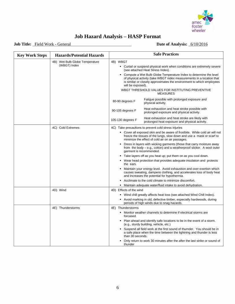
Job Hazard Analysis – HASP Format
Job Title: Field Work - General Date of Analysis: 6/10/2016
6
Key Work Steps Hazards/Potential Hazards Safe Practices
4B) Wet Bulb Globe Temperature (WBGT) Index
4B) WBGT
Curtail or suspend physical work when conditions are extremely severe (see attached Heat Stress Index).
Compute a Wet Bulb Globe Temperature Index to determine the level of physical activity (take WBGT index measurements in a location that is similar or closely approximates the environment to which employees will be exposed).
WBGT THRESHOLD VALUES FOR INSTITUTING PREVENTIVE MEASURES
80-90 degrees F
Fatigue possible with prolonged exposure and physical activity.
90-105 degrees F
Heat exhaustion and heat stroke possible with prolonged exposure and physical activity.
105-130 degrees F
Heat exhaustion and heat stroke are likely with prolonged heat exposure and physical activity.
4C) Cold Extremes 4C) Take precautions to prevent cold stress injuries
Cover all exposed skin and be aware of frostbite. While cold air will not freeze the tissues of the lungs, slow down and use a mask or scarf to minimize the effect of cold air on air passages.
Dress in layers with wicking garments (those that carry moisture away from the body – e.g., cotton) and a weatherproof slicker. A wool outer garment is recommended.
Take layers off as you heat up; put them on as you cool down.
Wear head protection that provides adequate insulation and protects the ears.
Maintain your energy level. Avoid exhaustion and over-exertion which causes sweating, dampens clothing, and accelerates loss of body heat and increases the potential for hypothermia.
Acclimate to the cold climate to minimize discomfort.
Maintain adequate water/fluid intake to avoid dehydration.
4D) Wind 4D) Effects of the wind
Wind chill greatly affects heat loss (see attached Wind Chill Index).
Avoid marking in old, defective timber, especially hardwoods, during periods of high winds due to snag hazards.
4E) Thunderstorms 4E) Thunderstorms
Monitor weather channels to determine if electrical storms are forcased.
Plan ahead and identify safe locations to be in the event of a storm. (e.g., sturdy building, vehicle, etc.)
Suspend all field work at the first sound of thurnder. You should be in a safe place when the time between the lightning and thunder is less than 30 seconds.
Only return to work 30 minutes after the after the last strike or sound of thunder
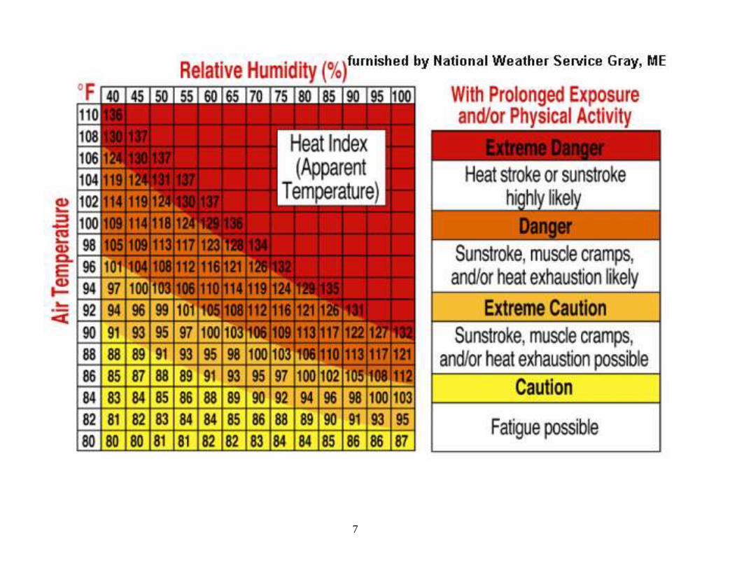
7
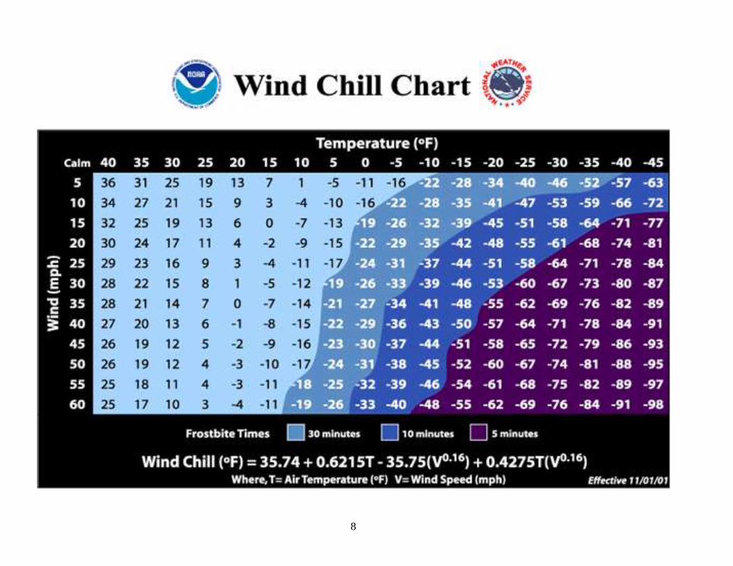
8
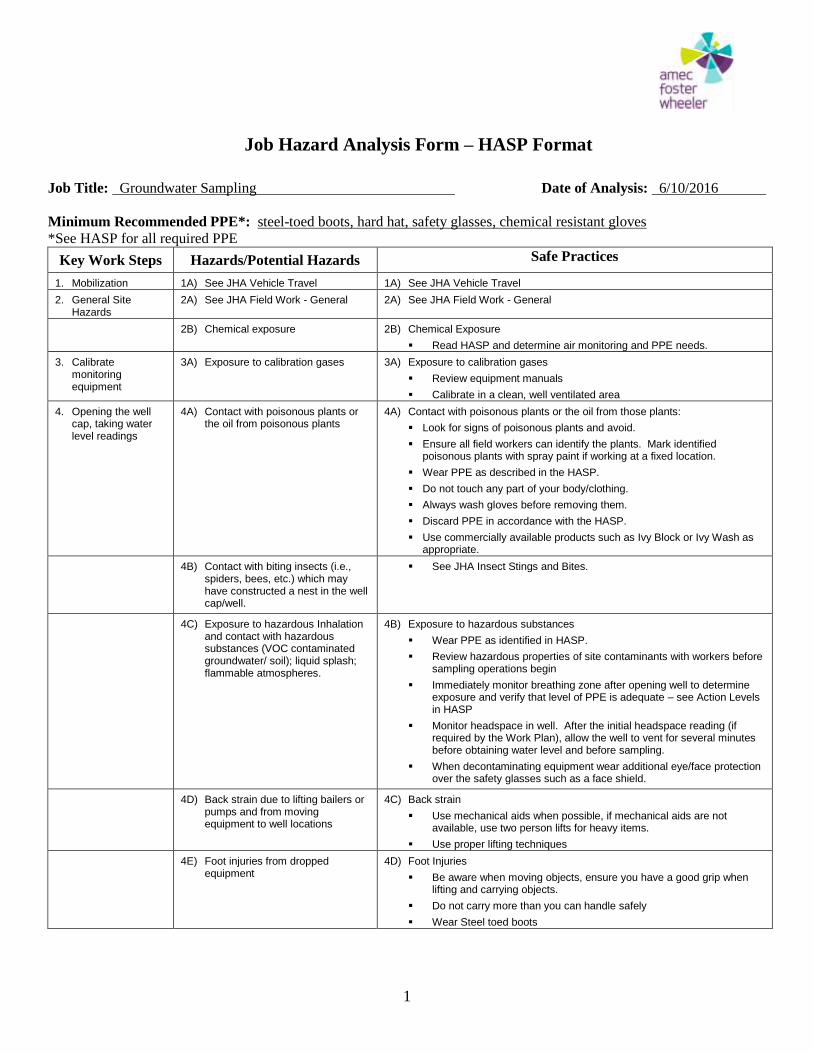
Job Hazard Analysis Form – HASP Format
Job Title: Groundwater Sampling Date of Analysis: 6/10/2016
1
Minimum Recommended PPE*: steel-toed boots, hard hat, safety glasses, chemical resistant gloves
*See HASP for all required PPE
Key Work Steps Hazards/Potential Hazards Safe Practices
1. Mobilization 1A) See JHA Vehicle Travel 1A) See JHA Vehicle Travel
2. General Site Hazards
2A) See JHA Field Work - General 2A) See JHA Field Work - General
2B) Chemical exposure 2B) Chemical Exposure
Read HASP and determine air monitoring and PPE needs.
3. Calibrate monitoring equipment
3A) Exposure to calibration gases 3A) Exposure to calibration gases
Review equipment manuals
Calibrate in a clean, well ventilated area
4. Opening the well cap, taking water level readings
4A) Contact with poisonous plants or the oil from poisonous plants
4A) Contact with poisonous plants or the oil from those plants:
Look for signs of poisonous plants and avoid.
Ensure all field workers can identify the plants. Mark identified poisonous plants with spray paint if working at a fixed location.
Wear PPE as described in the HASP.
Do not touch any part of your body/clothing.
Always wash gloves before removing them.
Discard PPE in accordance with the HASP.
Use commercially available products such as Ivy Block or Ivy Wash as appropriate.
4B) Contact with biting insects (i.e., spiders, bees, etc.) which may have constructed a nest in the well cap/well.
See JHA Insect Stings and Bites.
4C) Exposure to hazardous Inhalation and contact with hazardous substances (VOC contaminated groundwater/ soil); liquid splash; flammable atmospheres.
4B) Exposure to hazardous substances
Wear PPE as identified in HASP.
Review hazardous properties of site contaminants with workers before sampling operations begin
Immediately monitor breathing zone after opening well to determine exposure and verify that level of PPE is adequate – see Action Levels in HASP
Monitor headspace in well. After the initial headspace reading (if required by the Work Plan), allow the well to vent for several minutes before obtaining water level and before sampling.
When decontaminating equipment wear additional eye/face protection over the safety glasses such as a face shield.
4D) Back strain due to lifting bailers or pumps and from moving equipment to well locations
4C) Back strain
Use mechanical aids when possible, if mechanical aids are not available, use two person lifts for heavy items.
Use proper lifting techniques
4E) Foot injuries from dropped equipment
4D) Foot Injuries
Be aware when moving objects, ensure you have a good grip when lifting and carrying objects.
Do not carry more than you can handle safely
Wear Steel toed boots

Job Hazard Analysis Form – HASP Format
Job Title: Groundwater Sampling Date of Analysis: 6/10/2016
2
Key Work Steps Hazards/Potential Hazards Safe Practices
5. Collecting water samples
5A) Fire/Explosion/Contamination hazard from refueling generators
5A) Fire/Explosion/Contamination hazard from refueling generators
Turn the generator off and let it cool down before refueling
Segregate fuel and other hydrocarbons from samples to minimize contamination potential
Transport fuels in approved safety containers. The use of containers other than those specifically designed to carry fuel is prohibited
See JHA for Gasoline use
5B) Electrocution 5B) Electrocution
A ground fault circuit interrupter (GFCI) device must protect all AC electrical circuits.
Use only correctly grounded equipment. Never use three-pronged cords which have had the third prong broken off.
Make sure that the electrical cords from generators and power tools are not allowed to be in contact with water
Do not stand in wet areas while operating power equipment
Always make sure all electrically-powered sampling equipment is in good repair. Report any problems so the equipment can be repaired or replaced.
When unplugging a cord, pull on the plug rather than the cord.
Never do repairs on electrical equipment unless you are both authorized and qualified to do so.
5C) Exposure to contaminants 5C) Exposure to Contaminants
Stand up wind when sampling
Monitor breathing zone with appropriate monitoring equipment (see HASP)
Wear chemical resistant PPE as identified in HASP
See section 4C) under Safe Practices above
5D) Infectious water born diseases 5D) Infectious water born diseases
Wear chemical resistant gloves and other PPE – as identified in HASP
Prevent water from contacting skin
Wash exposed skin with soap and water ASAP after sampling event
Ensure that all equipment is adequately decontaminated using a 10% bleach solution
5E) Exposure to water preservatives 5E) Exposure to water preservatives
Work in a well ventilated area, upwind of samples
Wear chemical resistant PPE as identified in HASP
When preserving samples always add acid to water, avoid the opposite.
See JHA Working with Preservatives
5F) Slips/trips/falls 5F) Slips/trips/falls
Ground can become wet/muddy, created by spilled water
Place all purged water in drums for removal
Wear good slip resistant footwear
5G) Repetitive Motion and other Ergonomic Issues
5G) Ergonomic Issues Use mechanical means where possible to raise and lower equipment
into well. Alternate raising and lowering equipment between field sampling team
members, and alternate bailing the well. Use safe lifting techniques.
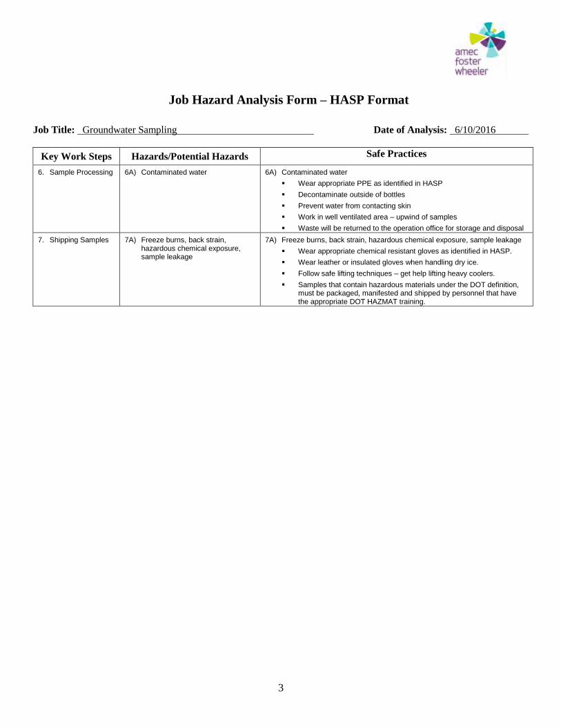
Job Hazard Analysis Form – HASP Format
Job Title: Groundwater Sampling Date of Analysis: 6/10/2016
3
Key Work Steps Hazards/Potential Hazards Safe Practices
6. Sample Processing 6A) Contaminated water 6A) Contaminated water
Wear appropriate PPE as identified in HASP
Decontaminate outside of bottles
Prevent water from contacting skin
Work in well ventilated area – upwind of samples
Waste will be returned to the operation office for storage and disposal
7. Shipping Samples 7A) Freeze burns, back strain, hazardous chemical exposure, sample leakage
7A) Freeze burns, back strain, hazardous chemical exposure, sample leakage
Wear appropriate chemical resistant gloves as identified in HASP.
Wear leather or insulated gloves when handling dry ice.
Follow safe lifting techniques – get help lifting heavy coolers.
Samples that contain hazardous materials under the DOT definition, must be packaged, manifested and shipped by personnel that have the appropriate DOT HAZMAT training.
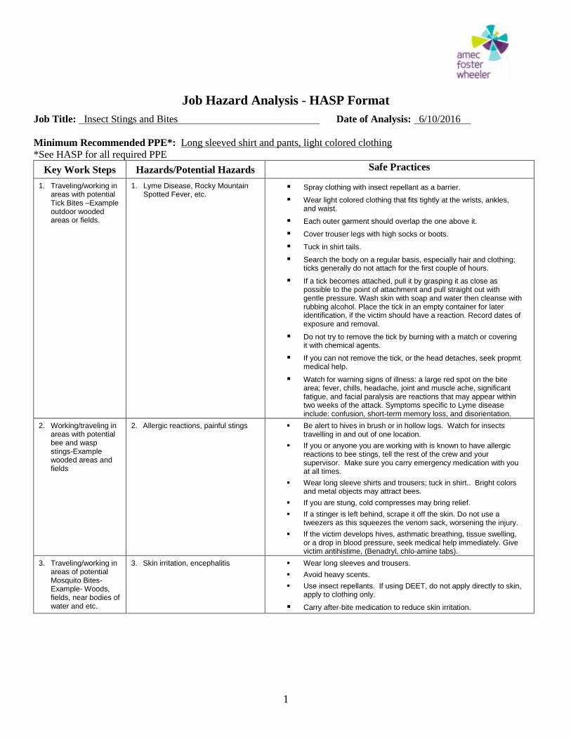
Job Hazard Analysis - HASP Format
Job Title: Insect Stings and Bites Date of Analysis: 6/10/2016
1
Minimum Recommended PPE*: Long sleeved shirt and pants, light colored clothing
*See HASP for all required PPE
Key Work Steps Hazards/Potential Hazards Safe Practices
1. Traveling/working in areas with potential Tick Bites –Example outdoor wooded areas or fields.
1. Lyme Disease, Rocky Mountain Spotted Fever, etc.
Spray clothing with insect repellant as a barrier.
Wear light colored clothing that fits tightly at the wrists, ankles, and waist.
Each outer garment should overlap the one above it.
Cover trouser legs with high socks or boots.
Tuck in shirt tails.
Search the body on a regular basis, especially hair and clothing; ticks generally do not attach for the first couple of hours.
If a tick becomes attached, pull it by grasping it as close as possible to the point of attachment and pull straight out with gentle pressure. Wash skin with soap and water then cleanse with rubbing alcohol. Place the tick in an empty container for later identification, if the victim should have a reaction. Record dates of exposure and removal.
Do not try to remove the tick by burning with a match or covering it with chemical agents.
If you can not remove the tick, or the head detaches, seek propmt medical help.
Watch for warning signs of illness: a large red spot on the bite area; fever, chills, headache, joint and muscle ache, significant fatigue, and facial paralysis are reactions that may appear within two weeks of the attack. Symptoms specific to Lyme disease include: confusion, short-term memory loss, and disorientation.
2. Working/traveling in areas with potential bee and wasp stings-Example wooded areas and fields
2. Allergic reactions, painful stings Be alert to hives in brush or in hollow logs. Watch for insects travelling in and out of one location.
If you or anyone you are working with is known to have allergic reactions to bee stings, tell the rest of the crew and your supervisor. Make sure you carry emergency medication with you at all times.
Wear long sleeve shirts and trousers; tuck in shirt.. Bright colors and metal objects may attract bees.
If you are stung, cold compresses may bring relief.
If a stinger is left behind, scrape it off the skin. Do not use a tweezers as this squeezes the venom sack, worsening the injury.
If the victim develops hives, asthmatic breathing, tissue swelling, or a drop in blood pressure, seek medical help immediately. Give victim antihistime, (Benadryl, chlo-amine tabs).
3. Traveling/working in areas of potential Mosquito Bites- Example- Woods, fields, near bodies of water and etc.
3. Skin irritation, encephalitis Wear long sleeves and trousers.
Avoid heavy scents.
Use insect repellants. If using DEET, do not apply directly to skin, apply to clothing only.
Carry after-bite medication to reduce skin irritation.
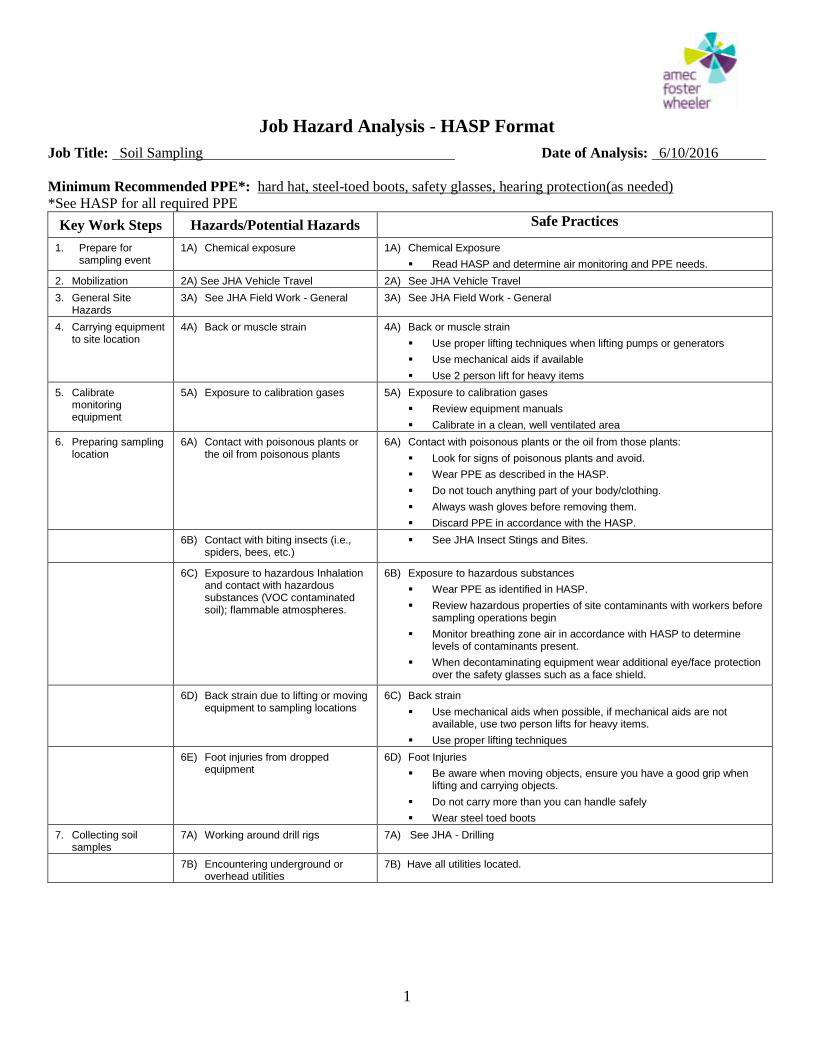
Job Hazard Analysis - HASP Format
Job Title: Soil Sampling Date of Analysis: 6/10/2016
1
Minimum Recommended PPE*: hard hat, steel-toed boots, safety glasses, hearing protection(as needed)
*See HASP for all required PPE
Key Work Steps Hazards/Potential Hazards Safe Practices
1. Prepare for sampling event
1A) Chemical exposure 1A) Chemical Exposure
Read HASP and determine air monitoring and PPE needs.
2. Mobilization 2A) See JHA Vehicle Travel 2A) See JHA Vehicle Travel
3. General Site Hazards
3A) See JHA Field Work - General 3A) See JHA Field Work - General
4. Carrying equipment to site location
4A) Back or muscle strain 4A) Back or muscle strain
Use proper lifting techniques when lifting pumps or generators
Use mechanical aids if available
Use 2 person lift for heavy items
5. Calibrate monitoring equipment
5A) Exposure to calibration gases 5A) Exposure to calibration gases
Review equipment manuals
Calibrate in a clean, well ventilated area
6. Preparing sampling location
6A) Contact with poisonous plants or the oil from poisonous plants
6A) Contact with poisonous plants or the oil from those plants:
Look for signs of poisonous plants and avoid.
Wear PPE as described in the HASP.
Do not touch anything part of your body/clothing.
Always wash gloves before removing them.
Discard PPE in accordance with the HASP.
6B) Contact with biting insects (i.e., spiders, bees, etc.)
See JHA Insect Stings and Bites.
6C) Exposure to hazardous Inhalation and contact with hazardous substances (VOC contaminated soil); flammable atmospheres.
6B) Exposure to hazardous substances
Wear PPE as identified in HASP.
Review hazardous properties of site contaminants with workers before sampling operations begin
Monitor breathing zone air in accordance with HASP to determine levels of contaminants present.
When decontaminating equipment wear additional eye/face protection over the safety glasses such as a face shield.
6D) Back strain due to lifting or moving equipment to sampling locations
6C) Back strain
Use mechanical aids when possible, if mechanical aids are not available, use two person lifts for heavy items.
Use proper lifting techniques
6E) Foot injuries from dropped equipment
6D) Foot Injuries
Be aware when moving objects, ensure you have a good grip when lifting and carrying objects.
Do not carry more than you can handle safely
Wear steel toed boots
7. Collecting soil samples
7A) Working around drill rigs 7A) See JHA - Drilling
7B) Encountering underground or overhead utilities
7B) Have all utilities located.
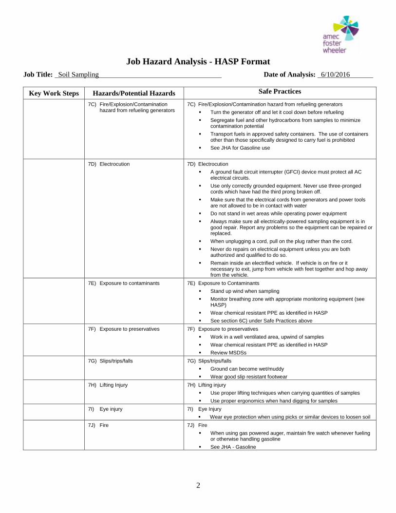
Job Hazard Analysis - HASP Format
Job Title: Soil Sampling Date of Analysis: 6/10/2016
2
Key Work Steps Hazards/Potential Hazards Safe Practices
7C) Fire/Explosion/Contamination hazard from refueling generators
7C) Fire/Explosion/Contamination hazard from refueling generators
Turn the generator off and let it cool down before refueling
Segregate fuel and other hydrocarbons from samples to minimize contamination potential
Transport fuels in approved safety containers. The use of containers other than those specifically designed to carry fuel is prohibited
See JHA for Gasoline use
7D) Electrocution 7D) Electrocution
A ground fault circuit interrupter (GFCI) device must protect all AC electrical circuits.
Use only correctly grounded equipment. Never use three-pronged cords which have had the third prong broken off.
Make sure that the electrical cords from generators and power tools are not allowed to be in contact with water
Do not stand in wet areas while operating power equipment
Always make sure all electrically-powered sampling equipment is in good repair. Report any problems so the equipment can be repaired or replaced.
When unplugging a cord, pull on the plug rather than the cord.
Never do repairs on electrical equipment unless you are both authorized and qualified to do so.
Remain inside an electrified vehicle. If vehicle is on fire or it necessary to exit, jump from vehicle with feet together and hop away from the vehicle.
7E) Exposure to contaminants 7E) Exposure to Contaminants
Stand up wind when sampling
Monitor breathing zone with appropriate monitoring equipment (see HASP)
Wear chemical resistant PPE as identified in HASP
See section 6C) under Safe Practices above
7F) Exposure to preservatives 7F) Exposure to preservatives
Work in a well ventilated area, upwind of samples
Wear chemical resistant PPE as identified in HASP
Review MSDSs
7G) Slips/trips/falls 7G) Slips/trips/falls
Ground can become wet/muddy
Wear good slip resistant footwear
7H) Lifting Injury 7H) Lifting injury
Use proper lifting techniques when carrying quantities of samples
Use proper ergonomics when hand digging for samples
7I) Eye injury 7I) Eye Injury
Wear eye protection when using picks or similar devices to loosen soil
7J) Fire 7J) Fire
When using gas powered auger, maintain fire watch whenever fueling or otherwise handling gasoline
See JHA - Gasoline
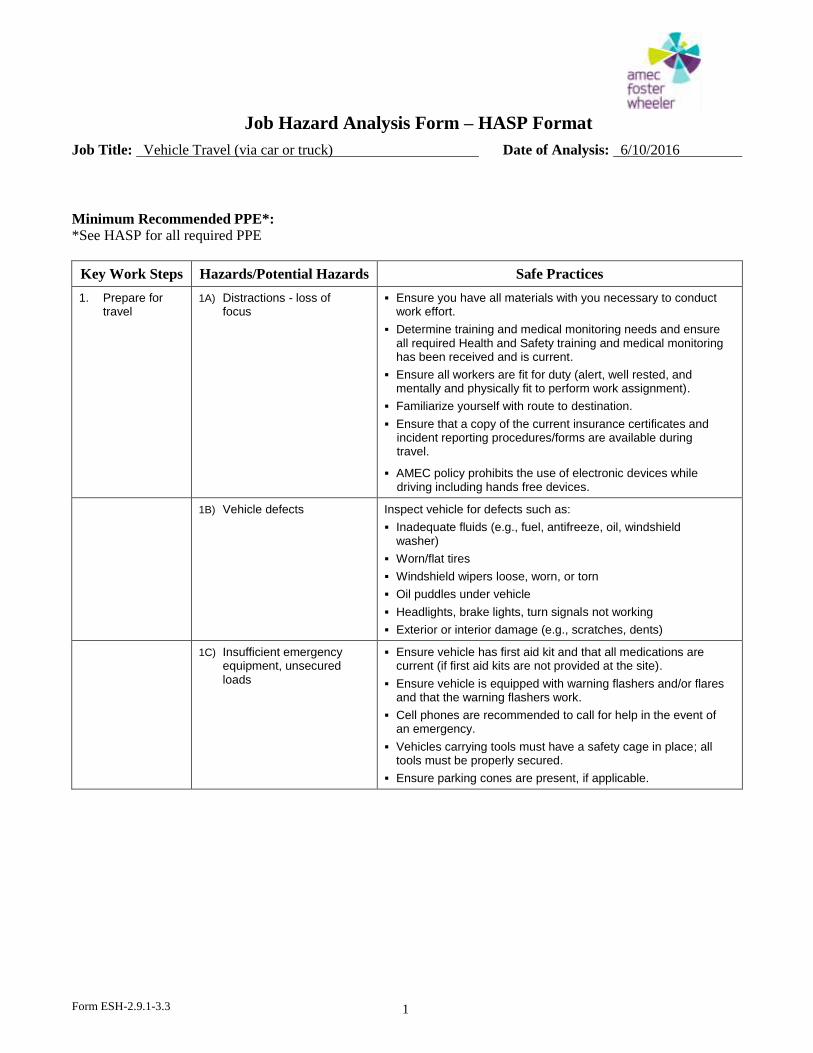
Job Hazard Analysis Form – HASP Format
Job Title: Vehicle Travel (via car or truck) Date of Analysis: 6/10/2016
Form ESH-2.9.1-3.3
1
Minimum Recommended PPE*: *See HASP for all required PPE
Key Work Steps Hazards/Potential Hazards Safe Practices
1. Prepare for travel
1A) Distractions - loss of focus
Ensure you have all materials with you necessary to conduct work effort.
Determine training and medical monitoring needs and ensure all required Health and Safety training and medical monitoring has been received and is current.
Ensure all workers are fit for duty (alert, well rested, and mentally and physically fit to perform work assignment).
Familiarize yourself with route to destination.
Ensure that a copy of the current insurance certificates and incident reporting procedures/forms are available during travel.
AMEC policy prohibits the use of electronic devices while driving including hands free devices.
1B) Vehicle defects Inspect vehicle for defects such as:
Inadequate fluids (e.g., fuel, antifreeze, oil, windshield washer)
Worn/flat tires
Windshield wipers loose, worn, or torn
Oil puddles under vehicle
Headlights, brake lights, turn signals not working
Exterior or interior damage (e.g., scratches, dents)
1C) Insufficient emergency equipment, unsecured loads
Ensure vehicle has first aid kit and that all medications are current (if first aid kits are not provided at the site).
Ensure vehicle is equipped with warning flashers and/or flares and that the warning flashers work.
Cell phones are recommended to call for help in the event of an emergency.
Vehicles carrying tools must have a safety cage in place; all tools must be properly secured.
Ensure parking cones are present, if applicable.
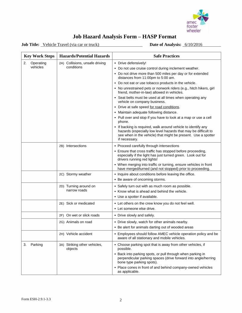
Job Hazard Analysis Form – HASP Format
Job Title: Vehicle Travel (via car or truck) Date of Analysis: 6/10/2016
Form ESH-2.9.1-3.3
2
Key Work Steps Hazards/Potential Hazards Safe Practices
2. Operating vehicles
2A) Collisions, unsafe driving conditions
Drive defensively!
Do not use cruise control during inclement weather.
Do not drive more than 500 miles per day or for extended distances from 11:00pm to 5:00 am.
Do not eat or use tobacco products in the vehicle.
No unrestrained pets or nonwork riders (e.g., hitch hikers, girl friend, mother-in-law) allowed in vehicles.
Seat belts must be used at all times when operating any vehicle on company business.
Drive at safe speed for road conditions.
Maintain adequate following distance.
Pull over and stop if you have to look at a map or use a cell phone.
If backing is required, walk around vehicle to identify any hazards (especially low level hazards that may be difficult to see when in the vehicle) that might be present. Use a spotter if necessary.
2B) Intersections Proceed carefully through intersections
Ensure that cross traffic has stopped before proceeding, especially if the light has just turned green. Look out for drivers running red lights!
When merging into traffic or turning, ensure vehicles in front have merged/turned (and not stopped) prior to proceeding.
2C) Stormy weather Inquire about conditions before leaving the office.
Be aware of oncoming storms.
2D) Turning around on narrow roads
Safely turn out with as much room as possible.
Know what is ahead and behind the vehicle.
Use a spotter if available.
2E) Sick or medicated Let others on the crew know you do not feel well.
Let someone else drive.
2F) On wet or slick roads Drive slowly and safely.
2G) Animals on road Drive slowly, watch for other animals nearby.
Be alert for animals darting out of wooded areas
2H) Vehicle accident Employees should follow AMEC vehicle operation policy and be aware of all stationary and mobile vehicles.
3. Parking 3A) Striking other vehicles, objects
Choose parking spot that is away from other vehicles, if possible.
Back into parking spots, or pull through when parking in perpendicular parking spaces (drive forward into angle/herring bone type parking spots).
Place cones in front of and behind company-owned vehicles as applicable.
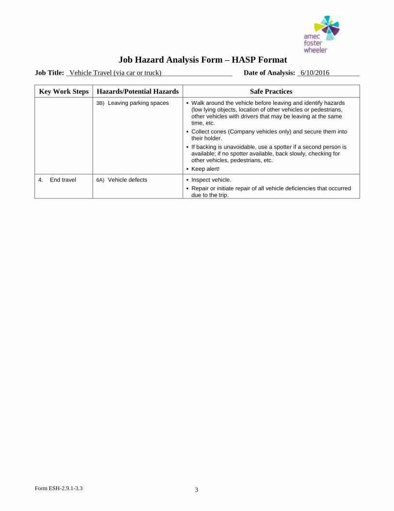
Job Hazard Analysis Form – HASP Format
Job Title: Vehicle Travel (via car or truck) Date of Analysis: 6/10/2016
Form ESH-2.9.1-3.3
3
Key Work Steps Hazards/Potential Hazards Safe Practices
3B) Leaving parking spaces Walk around the vehicle before leaving and identify hazards (low lying objects, location of other vehicles or pedestrians, other vehicles with drivers that may be leaving at the same time, etc.
Collect cones (Company vehicles only) and secure them into their holder.
If backing is unavoidable, use a spotter if a second person is available; if no spotter available, back slowly, checking for other vehicles, pedestrians, etc.
Keep alert!
4. End travel 6A) Vehicle defects Inspect vehicle.
Repair or initiate repair of all vehicle deficiencies that occurred due to the trip.
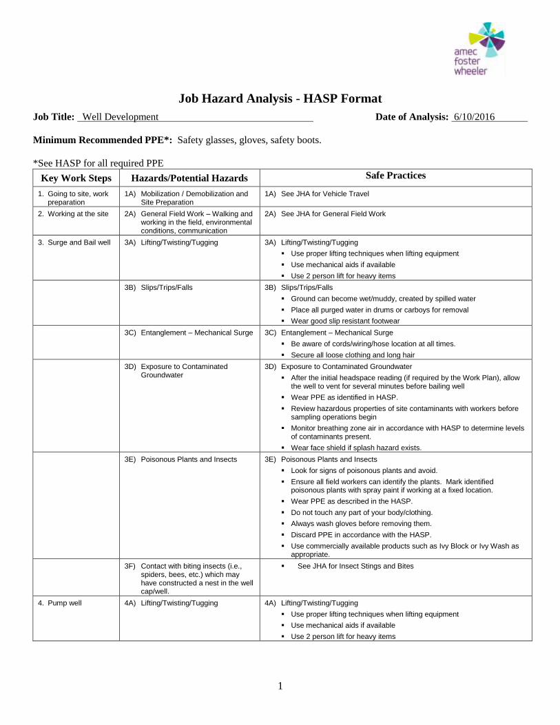
Job Hazard Analysis - HASP Format
Job Title: Well Development Date of Analysis: 6/10/2016
1
Minimum Recommended PPE*: Safety glasses, gloves, safety boots.
*See HASP for all required PPE
Key Work Steps Hazards/Potential Hazards Safe Practices
1. Going to site, work preparation
1A) Mobilization / Demobilization and Site Preparation
1A) See JHA for Vehicle Travel
2. Working at the site 2A) General Field Work – Walking and working in the field, environmental conditions, communication
2A) See JHA for General Field Work
3. Surge and Bail well 3A) Lifting/Twisting/Tugging 3A) Lifting/Twisting/Tugging
Use proper lifting techniques when lifting equipment
Use mechanical aids if available
Use 2 person lift for heavy items
3B) Slips/Trips/Falls 3B) Slips/Trips/Falls
Ground can become wet/muddy, created by spilled water
Place all purged water in drums or carboys for removal
Wear good slip resistant footwear
3C) Entanglement – Mechanical Surge 3C) Entanglement – Mechanical Surge
Be aware of cords/wiring/hose location at all times.
Secure all loose clothing and long hair
3D) Exposure to Contaminated Groundwater
3D) Exposure to Contaminated Groundwater
After the initial headspace reading (if required by the Work Plan), allow the well to vent for several minutes before bailing well
Wear PPE as identified in HASP.
Review hazardous properties of site contaminants with workers before sampling operations begin
Monitor breathing zone air in accordance with HASP to determine levels of contaminants present.
Wear face shield if splash hazard exists.
3E) Poisonous Plants and Insects 3E) Poisonous Plants and Insects
Look for signs of poisonous plants and avoid.
Ensure all field workers can identify the plants. Mark identified poisonous plants with spray paint if working at a fixed location.
Wear PPE as described in the HASP.
Do not touch any part of your body/clothing.
Always wash gloves before removing them.
Discard PPE in accordance with the HASP.
Use commercially available products such as Ivy Block or Ivy Wash as appropriate.
3F) Contact with biting insects (i.e., spiders, bees, etc.) which may have constructed a nest in the well cap/well.
See JHA for Insect Stings and Bites
4. Pump well 4A) Lifting/Twisting/Tugging 4A) Lifting/Twisting/Tugging
Use proper lifting techniques when lifting equipment
Use mechanical aids if available
Use 2 person lift for heavy items
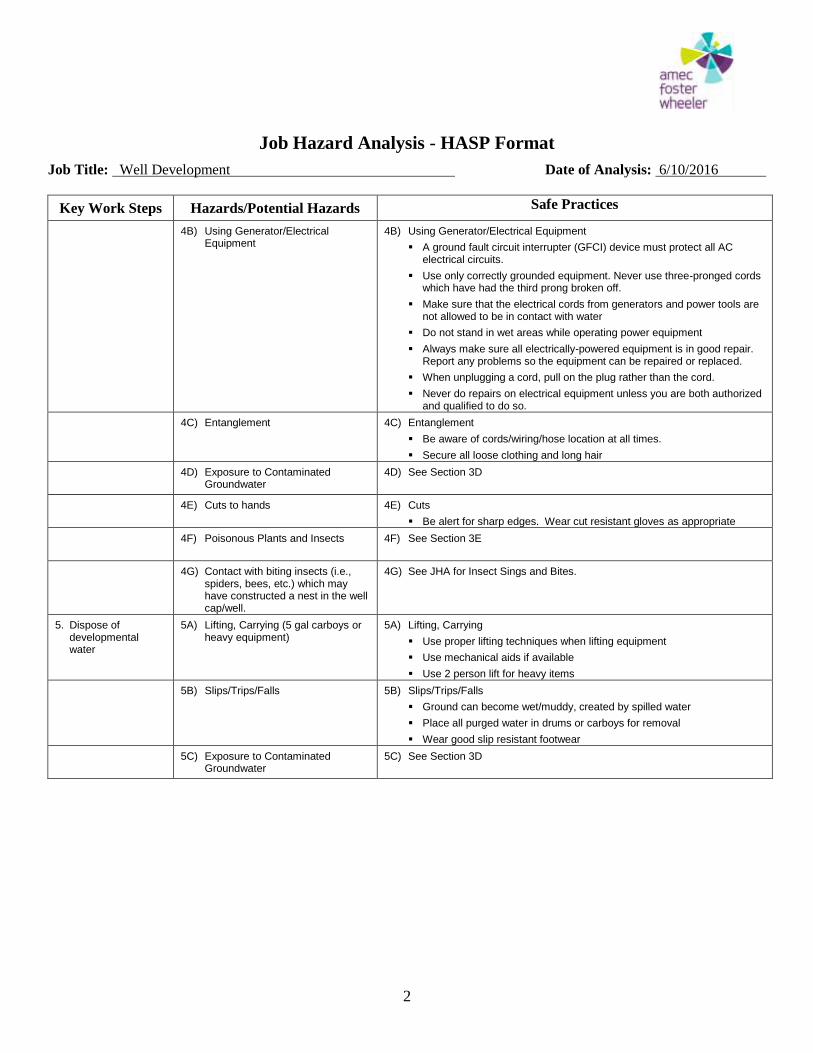
Job Hazard Analysis - HASP Format
Job Title: Well Development Date of Analysis: 6/10/2016
2
Key Work Steps Hazards/Potential Hazards Safe Practices
4B) Using Generator/Electrical Equipment
4B) Using Generator/Electrical Equipment
A ground fault circuit interrupter (GFCI) device must protect all AC electrical circuits.
Use only correctly grounded equipment. Never use three-pronged cords which have had the third prong broken off.
Make sure that the electrical cords from generators and power tools are not allowed to be in contact with water
Do not stand in wet areas while operating power equipment
Always make sure all electrically-powered equipment is in good repair. Report any problems so the equipment can be repaired or replaced.
When unplugging a cord, pull on the plug rather than the cord.
Never do repairs on electrical equipment unless you are both authorized and qualified to do so.
4C) Entanglement 4C) Entanglement
Be aware of cords/wiring/hose location at all times.
Secure all loose clothing and long hair
4D) Exposure to Contaminated Groundwater
4D) See Section 3D
4E) Cuts to hands 4E) Cuts
Be alert for sharp edges. Wear cut resistant gloves as appropriate
4F) Poisonous Plants and Insects 4F) See Section 3E
4G) Contact with biting insects (i.e., spiders, bees, etc.) which may have constructed a nest in the well cap/well.
4G) See JHA for Insect Sings and Bites.
5. Dispose of developmental water
5A) Lifting, Carrying (5 gal carboys or heavy equipment)
5A) Lifting, Carrying
Use proper lifting techniques when lifting equipment
Use mechanical aids if available
Use 2 person lift for heavy items
5B) Slips/Trips/Falls 5B) Slips/Trips/Falls
Ground can become wet/muddy, created by spilled water
Place all purged water in drums or carboys for removal
Wear good slip resistant footwear
5C) Exposure to Contaminated Groundwater
5C) See Section 3D
Additional RCRA Facility Investigation Work Plan (REV 1) Apex Tools Group Facility Apex, North Carolina
APPENDIX B
Standard Operating Procedures
Amec Foster Wheeler Environment & Infrastructure, Inc. Tel: (919) 381-9900 4021 Stirrup Creek Drive, Suite 100 Fax: (919) 381-9901 Durham, North Carolina 27703 www.amecfw.com
APPENDIX B STANDARD OPERATING PROCEDURES
Assessment and Field Data Collection The Standard Operating Procedures have utilized, where applicable, the field methods, sampling procedures, sample custody, and field quality assurance as outlined in the Environmental Compliance Branch Environmental Investigations Standard Operating Procedures and Quality Assurance Manual, November 2001, (EISOPQAM), U.S. EPA Region IV Science and Environmental Services Division, Athens, Georgia. The Standard Operating Procedures has incorporated changes presented in The Field Branches Quality System and Technical Procedures that now supersede the "Environmental Investigations Standard Operating Procedures and Quality Assurance Manual" (EISOPQAM), November 2001, and the "Ecological Assessment Standard Operating Procedures and Quality Assurance Manual" (EASOPQAM), January 2002. These procedures contain routine field sampling and measurement procedures, and quality control documents used by field investigators of the two Science and Ecosystem Support Division (SESD) Field Branches: the Ecological Assessment Branch and the Enforcement and Investigations Branch. The specific sampling and field measurement procedures presented in SESD Quality System and Technical Procedures are based on the experience of the field investigators within the field branches and accepted professional practices which are referenced in each procedure. These documents are intended to be dynamic and will be periodically reviewed and updated, as needed. It is the responsibility of the user to ensure they are using the most recent version of the procedures.
Amec Foster Wheeler Environment & Infrastructure, Inc. Tel: (919) 381-9900 4021 Stirrup Creek Drive, Suite 100 Fax: (919) 381-9901 Durham, North Carolina 27703 www.amecfw.com
Decontamination and Cross-contamination Prevention Standard Operating Procedures #001
The following procedures shall be implemented to ensure sample collection and other related equipment is properly decontaminated to prevent possible cross-contamination of samples. It is imperative that equipment be properly decontaminated and measures be implemented to prevent cross-contamination of field and sample collection equipment and actual samples that are collected. 1. All work should proceed from areas of suspected or know low contamination to areas
of suspected or known high contamination.
2. All heavy equipment (e.g., drill rigs, backhoes, etc.) shall be decontaminated prior to coming on-site for work and all down-hole drilling equipment (e.g., auger flights, drilling rods, split spoons, etc.) shall be decontaminated between each drilling/sampling location.
A decontamination station/pad shall be established for cleaning down-hole equipment. Decontamination wastes shall be contained and collected for disposal.
Large equipment (e.g., augers, drilling rods) shall be decontaminated using a steam cleaner while use of a soap solution may be appropriate for smaller pieces of equipment (e.g., split spoons).
3. All equipment utilized in water level measurement, sample collection, or that otherwise contacts material to be sampled will be decontaminated between each location and prior to returning to its case and being stowed with other equipment.
Personnel involved with equipment decontamination shall wear clean gloves during the decontamination process.
Cleaning shall be performed using a soap solution (e.g., Alconox, Liqui-Nox) with a distilled water rinse. If equipment has contacted free product, the decontamination process shall include an isopropyl alcohol rinse. All wash and rinse activities shall be performed in buckets or other suitable containers. Used water should be contained in 55-gallon drums for disposal.
Reusable sampling equipment that has been cleaned for later use (e.g., steel trowels, hand auger buckets, etc.) shall be wrapped in clean aluminum foil or sealed in plastic bags until used.
4. Field personnel shall use clean gloves when handling any sampling equipment and shall avoid contacting sampling equipment with other potentially contaminated surfaces and materials. New gloves shall be used whenever a new sample is collected or when a break in sampling occurs (e.g. between well purging and sampling).
5. Investigation derived waste (lDW) and other trash and debris shall be staged away from sampling equipment and other materials to avoid potential cross-contamination.
6. Any samples that contain elevated concentrations of contaminants compared to other samples shall be stored and shipped in a separate cooler/container. Trip blanks should be sent in any cooler where volatile organic compound (VOC) samples are collected for analysis.
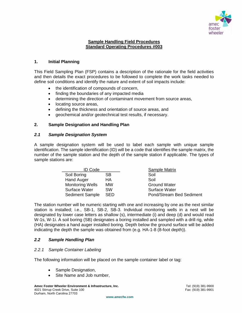
Amec Foster Wheeler Environment & Infrastructure, Inc. Tel: (919) 381-9900 4021 Stirrup Creek Drive, Suite 100 Fax: (919) 381-9901 Durham, North Carolina 27703 www.amecfw.com
Sample Handling Field Procedures Standard Operating Procedures #003
1. Initial Planning This Field Sampling Plan (FSP) contains a description of the rationale for the field activities and then details the exact procedures to be followed to complete the work tasks needed to define soil conditions and identify the nature and extent of soil impacts include:
the identification of compounds of concern,
finding the boundaries of any impacted media
determining the direction of contaminant movement from source areas,
locating source areas,
defining the thickness and orientation of source areas, and
geochemical and/or geotechnical test results, if necessary. 2. Sample Designation and Handling Plan 2.1 Sample Designation System A sample designation system will be used to label each sample with unique sample identification. The sample identification (ID) will be a code that identifies the sample matrix, the number of the sample station and the depth of the sample station if applicable. The types of sample stations are: ID Code Sample Matrix
Soil Boring SB Soil Hand Auger HA Soil Monitoring Wells MW Ground Water Surface Water SW Surface Water Sediment Sample SED Pond/Stream Bed Sediment
The station number will be numeric starting with one and increasing by one as the next similar station is installed; i.e., SB-1, SB-2, SB-3. Individual monitoring wells in a nest will be designated by lower case letters as shallow (s), intermediate (i) and deep (d) and would read W-1s, W-1i. A soil boring (SB) designates a boring installed and sampled with a drill rig, while (HA) designates a hand auger installed boring. Depth below the ground surface will be added indicating the depth the sample was obtained from (e.g. HA-1-8 (8-foot depth)). 2.2 Sample Handling Plan 2.2.1 Sample Container Labeling The following information will be placed on the sample container label or tag:
Sample Designation,
Site Name and Job number,
Amec Foster Wheeler Environment & Infrastructure, Inc. Tel: (919) 381-9900 4021 Stirrup Creek Drive, Suite 100 Fax: (919) 381-9901 Durham, North Carolina 27703 www.amecfw.com
Sample Date and Time,
Sampler's Name or Initials,
Type of Sample - Grab or Composite,
Type of Analysis with Method Number,
Type of Preservative, and
Any Special Requirements. The sampling team and team leader will review the work plan. A schedule of the number of locations to be sampled each day will be prepared by the team leader and project manager. The site HASP has been prepared by the corporate health and safety officer and reviewed with the team leader. The team leader will review the site HASP with the sampling team. The team leader will finalize sampling locations. The sampling order will proceed from lowest concentration of constituents of concern to highest concentration of constituent of concern areas. 2.2.2 Sample Custody Once the samples are removed from the sampling device, they will be transferred to properly labeled containers, logged into the field notebook, and placed into a cooler with sufficient ice to maintain sample temperature at 4°C ± 2°C. When full, or when the sampling is complete, the cooler will be closed and taped shut. Proper custody of the samples will be maintained at all times. Sample coolers will be locked in the field truck during times when they will be out of direct view. Custody of the samples will remain with the sampling team until relinquishment to a courier or the analytical laboratory. A chain-of-custody (C-of-C) form will accompany each sample cooler from the time the cooler is closed and sealed until receipt by the analytical laboratory. A C-of-C record will accompany the sample from initial sample collection in the field to its receipt at the laboratory. The completed original will be returned to AMEC as part of the final analytical report, and a copy will be retained by the laboratory for its files. C-of-C records will be maintained in a secured location in the field until they can be transferred to the AMEC's Durham office. 2.2.3 Sample Analyses and Other Sample Handling Requirements The work plan or proposal submitted to the client contains a review of analytical tests to be performed on the soil, sediment, ground water, and surface waters at the Site. The chosen analytical laboratory will provide the type and sizes of sample containers required, sample preservative methods, shipping requirements, holding and extraction times, and methods to maintain the laboratory QA/QC. 2.2.4 Documentation Documentation of field activities will be consist of daily field logs, drilling logs for all soil borings, rock corings, and monitoring well installations, and sample logs for collected samples.

Amec Foster Wheeler Environment & Infrastructure, Inc. Tel: (919) 381-9900 4021 Stirrup Creek Drive, Suite 100 Fax: (919) 381-9901 Durham, North Carolina 27703 www.amecfw.com
Documentation records will be kept in a secure location in the field until transferred to the Durham office.
Amec Foster Wheeler Environment & Infrastructure, Inc. Tel: (919) 381-9900 4021 Stirrup Creek Drive, Suite 100 Fax: (919) 381-9901 Durham, North Carolina 27703 www.amecfw.com
Shallow Monitoring Well and Piezometer Installation Standard Operating Procedures #007
Shallow monitoring wells and piezometers are installed in unconsolidated material to provide secure sampling points for the uppermost zones of water table (unconfined) aquifers. Following boring termination (typically borings advanced using hollow-stem augers), the well is constructed. The well is built within the hollow stem of the augers as this allows for protection of the welt screen against collapse of the borehole before the well filter pack is properly emplaced. The auger flights may be removed from the ground prior to well construction if there is reason to believe that the borehole will not collapse. If a well is constructed within a borehole advanced using air rotary drilling or direct push technology, the drilling equipment must be removed prior to well construction. The following procedure is used for well construction: 1. Clean, flush-threaded well casing with slotted well screen (typically Schedule 40
polyvinyl chloride (PVC)) is lowered into the borehole. Compatibility of screen material and slot size with site conditions must be considered. Stainless steel well screen may be needed at extremely contaminated sites.
2. Filter sand is then gravity-fed into the annulus between the well screen and the inside of the augers as the augers are slowly pulled from the borehole (or between the well screen and the boring walls if the drilling equipment has been removed). Filter sand is added to a height of approximately one to two feet above the top of the screen.
3. A bentonite seal is emplaced above the sand filter pack (about one to two feet thick) to prevent vertical movement of ground water within the borehole (i.e., to prevent cross contamination from upper to lower zones). Bentonite pellets are placed into the annular space above the sand filter pack and then hydrated with distilled water to create a low permeability barrier.
4. A neat cement grout is then tremmie (gravity-fed, if the bentonite seal is within a few feet of the surface) into the remaining annulus to ground surface.
5. The uppermost portion of each well is constructed to protect the well casing from damage.
The protective cover may be finished above grade with a steel protective outer casing with locking cover. A slip cap is typically placed over the well casing to prevent dirt and debris from entering the well.
The protective cover may be finished at grade with a steel man way with a bolt-down cover. A locking, watertight expanding cap is placed on the well to prevent dirt, debris, and water from entering the well.
6. The following information is recorded to complete the Boring Log/Well Completion Record (see attached example of an appropriate well completion record form ):
Depth of borehole
Length of screen pipe and actual screened interval
Length of casing pipe
Screen slot size
Amec Foster Wheeler Environment & Infrastructure, Inc. Tel: (919) 381-9900 4021 Stirrup Creek Drive, Suite 100 Fax: (919) 381-9901 Durham, North Carolina 27703 www.amecfw.com
7. The top of casing (TOC of the wells is surveyed for horizontal and vertical control for use in evaluating hydraulic gradients.
8. Wells should be labeled when constructed (metal tags in or on well protective casing). A description of the well location should be included in the field notes.
9. If the well is to be used as a temporary (one-time) sampling point, cement grout is not placed above the bentonite seal. After sampling, the temporary well can be abandoned by either pulling the casing/screen and filling the borehole with cement grout, or by leaving the casing in place and filling the casing and annular space above the bentonite seal with cement grout.
10. Piezometers are installed when there is only a need to measure liquid levels (rather than collecting actual ground water samples). Piezometers are typically constructed with small diameter (1-inch) casing.
11. Prior to sampling, monitoring wells are developed to reduce the amount of sediment in well annular space. This enhances the flow of ground water from the formation into the well and helps to ensure that the samples collected are representative of the quality of water in the aquifer. The well may be developed using a bailer or small pump as follows:
A disposable bailer or decontaminated pump is lowered into the well and allowed to sink to the bottom of the well casing.
If the well is developed by manual bailing, the bailer is raised using periodic, sharp upward tugs (surges). The surging motion of the bailer causes water to be extracted from the formation, through the screen filter pack into the screen. This also causes fine material that may have been mixed into the filter pack during installation to become suspended in the well water so that it can be removed via bailing.
If the well is developed using a pump, the pump must be periodically raised with sharp tugs to facilitate the removal of sediment from the filter pack and well casing.
Well development continues with water removal and periodic surging until the bailed water becomes as clear as practical.
In some cases, the well will go dry before the "clear water" endpoint is reached. If this happens, the well should be given time to recharge and the process repeated. If, after several such attempts, the well water remains turbid, the development process can cease. It is possible that, in certain low-yielding geologic units, a well cannot be developed to the clear water condition in a practical length of time. The endpoint for well development should be coordinated with the Technical lead/Project Manager.
12. Well Abandonment - when a decision is made to abandon a monitoring well, the borehole should be sealed in such a manner that the well cannot act as a conduit for migration of contaminants from the ground surface to the water table or between aquifers. To properly abandon a well, the preferred method is to completely remove the well casing and screen from the borehole, clean out the borehole and backfill with a cement or bentonite grout, neat cement, or concrete.
As stated the preferred method should be to completely remove the well casing and screen from the borehole. For shallow wells this can be accomplished by attaching a drilling rig cable tool to the casing and slowly pulling the casing from the well.
Amec Foster Wheeler Environment & Infrastructure, Inc. Tel: (919) 381-9900 4021 Stirrup Creek Drive, Suite 100 Fax: (919) 381-9901 Durham, North Carolina 27703 www.amecfw.com
i. The clean borehole can then be backfilled with the appropriate grout material. The backfill material should be placed into the borehole from the bottom to the top by pressure grouting with the positive displacement method (tremmie method).
ii. The top 2 feet of the borehole should be poured with concrete to insure a secure surface seal (plug).
If the casing cannot be readily removed the well can be grouted with the casing left in the borehole. The preferred method in this case is as follows:
i. Pressure grout the borehole by placing the tremmie tube to the bottom of the well casing, which will be the well screen or the bottom sump area below the well screen.
ii. The pressurized grout is forced out through the well screen into the filter material and up the inside of the well casing sealing holes and breaks that are present.
iii. The tremmie tube is retracted slowly as the grout fills the casing.
iv. The casing is cut off even with the ground and filled with concrete to a depth of 2 feet below the surface. If the casing has been broken off below the surface, the grout should be tremmied to within 2 feet of the surface and then finished to the ground surface with concrete.
If geologic conditions warrant the complete removal of the well casing, sand pack and other well construction materials, the well must then be over drilled and grouted. After the casing materials have been removed from the borehole, the borehole should be cleaned out and pressure grouted with the approved grouting materials. As previously stated, the borehole should be finished with a concrete surface plug.
13. Temporary Monitoring Well Types· five types of monitoring wells which have been shown to be acceptable are presented in the order of increasing difficulty to install and increasing cost:
No Filter Pack - this is the most common temporary well and is very effective in many situations. After the borehole is completed, the casing and screen are simply inserted. This is the most inexpensive and fastest well to install. This type well is extremely sensitive to turbidity fluctuations, because there is no filter pack. Care should be taken to not disturb the casing during purging and sampling.
Inner Filter Pack - this differs from the "No Pack" in that a filter pack is placed inside the screen to a level approximately 6 inches above the well screen. This ensures that all water within the casing has passed through the filter pack. For this type well to function properly, the static water level must be 6·to 12 inches above the filter pack.
Traditional Filter Pack - for this type, the screen and casing are inserted into the borehole, and the sand is poured into the annular space surrounding the screen and casing. Occasionally, it may be difficult to effectively place a filter pack around shallow open boreholes, due to collapse. This method requires more

Amec Foster Wheeler Environment & Infrastructure, Inc. Tel: (919) 381-9900 4021 Stirrup Creek Drive, Suite 100 Fax: (919) 381-9901 Durham, North Carolina 27703 www.amecfw.com
sand than the "inner filter pack" well, increasing material costs. As the filter pack is placed, it mixes with the muddy water in the borehole, which may increase the amount of time needed to purge the well to an acceptable level of turbidity.
Double Filter Pack·- the borehole is advanced to the desired depth. As with the "inner filter pack" the well screen is filled with filter pack material and the well screen and casing inserted until the top of the filter pack is at least 6 inches below the water table. Filter pack material is poured into the annular space around the well screen. This type temporary well construction can be very effective in aquifers where fine silts or clays predominate. This construction technique takes longer to implement and uses more filter pack material than others previously discussed.
Well-in-a-Well - the borehole is advanced to the desired depth. At this point, a l-inch well screen and sufficient riser is inserted into a 2-inch well screen with sufficient riser, and centered. Filter pack material is then placed into the annular space surrounding the 1-Inch well screen, to approximately 6 inches above the screen. The well is then inserted into the borehole. This system requires twice as much well screen and casing, with subsequent increase in material cost. The increased amount of well construction materials results in a corresponding increase in decontamination time and costs. If pre-packed wells are used, a higher degree of QA/QC will result in higher overall cost.
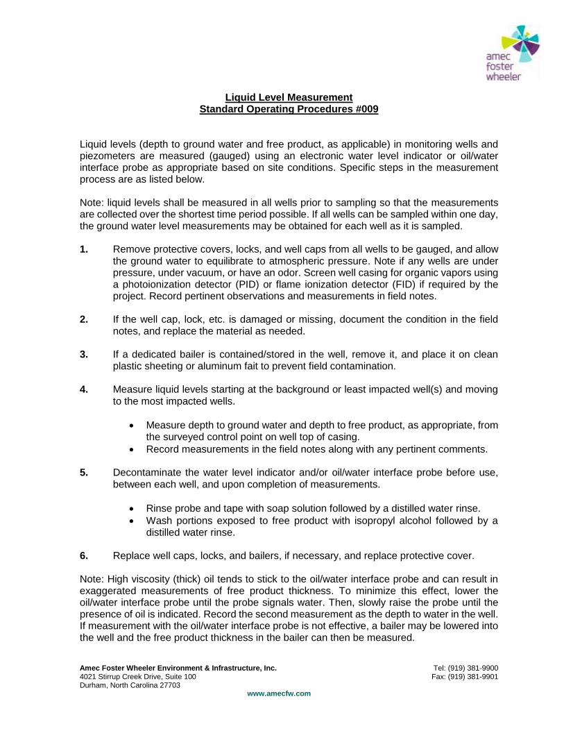
Amec Foster Wheeler Environment & Infrastructure, Inc. Tel: (919) 381-9900 4021 Stirrup Creek Drive, Suite 100 Fax: (919) 381-9901 Durham, North Carolina 27703 www.amecfw.com
Liquid Level Measurement Standard Operating Procedures #009
Liquid levels (depth to ground water and free product, as applicable) in monitoring wells and piezometers are measured (gauged) using an electronic water level indicator or oil/water interface probe as appropriate based on site conditions. Specific steps in the measurement process are as listed below. Note: liquid levels shall be measured in all wells prior to sampling so that the measurements are collected over the shortest time period possible. If all wells can be sampled within one day, the ground water level measurements may be obtained for each well as it is sampled. 1. Remove protective covers, locks, and well caps from all wells to be gauged, and allow
the ground water to equilibrate to atmospheric pressure. Note if any wells are under pressure, under vacuum, or have an odor. Screen well casing for organic vapors using a photoionization detector (PID) or flame ionization detector (FID) if required by the project. Record pertinent observations and measurements in field notes.
2. If the well cap, lock, etc. is damaged or missing, document the condition in the field
notes, and replace the material as needed. 3. If a dedicated bailer is contained/stored in the well, remove it, and place it on clean
plastic sheeting or aluminum fait to prevent field contamination. 4. Measure liquid levels starting at the background or least impacted well(s) and moving
to the most impacted wells.
Measure depth to ground water and depth to free product, as appropriate, from the surveyed control point on well top of casing.
Record measurements in the field notes along with any pertinent comments.
5. Decontaminate the water level indicator and/or oil/water interface probe before use, between each well, and upon completion of measurements.
Rinse probe and tape with soap solution followed by a distilled water rinse.
Wash portions exposed to free product with isopropyl alcohol followed by a distilled water rinse.
6. Replace well caps, locks, and bailers, if necessary, and replace protective cover. Note: High viscosity (thick) oil tends to stick to the oil/water interface probe and can result in exaggerated measurements of free product thickness. To minimize this effect, lower the oil/water interface probe until the probe signals water. Then, slowly raise the probe until the presence of oil is indicated. Record the second measurement as the depth to water in the well. If measurement with the oil/water interface probe is not effective, a bailer may be lowered into the well and the free product thickness in the bailer can then be measured.
COPY

______________________________________________________________________________________ SESD Operating Procedure Page 2 of 24 SESDPROC-300-R3 Soil Sampling Soil Sampling(300)_AF.R3 Effective Date: August 21, 2014
Revision History
The top row of this table shows the most recent changes to this controlled document. For
previous revision history information, archived versions of this document are maintained
by the SESD Document Control Coordinator on the SESD local area network (LAN).
History Effective Date
SESDPROC-300-R3, Soil Sampling, replaces SESDPROC-
300-R2.
General: Corrected any typographical, grammatical and/or editorial
errors.
Title Page: Updated the author from Fred Sloan to Kevin Simmons.
Updated the Enforcement and Investigations Branch Chief from Archie
Lee to Acting Chief, John Deatrick.
Section 1.5.1: Added “The reader should” to last sentence of the
paragraph.
Section 1.5.2: Omitted “When sampling in landscaped areas,” from first
sentence of eighth bullet.
Section 3.2.4: In the first paragraph, first sentence, added “(rapidly form
bubbles).” Omitted “(rapidly form bubbles)” from second paragraph,
second sentence.
Any reference to “Percent Moisture and Preservation Compatibility
(MOICA)” or “Percent Moisture” was changed to “Percent Solids”, both
in the text and in Table 1.
August 21, 2014
SESDPROC-300-R2, Soil Sampling, replaces SESDPROC-
300-R1.
December 20, 2011
SESDPROC-300-R1, Soil Sampling, replaces SESDPROC-
300-R0.
November 1, 2007
SESDPROC-300-R0, Soil Sampling, Original Issue February 05, 2007
COPY
______________________________________________________________________________________ SESD Operating Procedure Page 3 of 24 SESDPROC-300-R3 Soil Sampling Soil Sampling(300)_AF.R3 Effective Date: August 21, 2014
TABLE OF CONTENTS
1 General Information ................................................................................................. 5 1.1 Purpose................................................................................................................ 5 1.2 Scope/Application .............................................................................................. 5 1.3 Documentation/Verification .............................................................................. 5 1.4 References ........................................................................................................... 5 1.5 General Precautions........................................................................................... 6
1.5.1 Safety ............................................................................................................ 6 1.5.2 Procedural Precautions ............................................................................... 6
2 Special Sampling Considerations ............................................................................ 8 2.1 Special Precautions for Trace Contaminant Soil Sampling ........................... 8 2.2 Sample Homogenization .................................................................................... 8
2.3 Dressing Soil Surfaces........................................................................................ 9 2.4 Quality Control .................................................................................................. 9 2.5 Records................................................................................................................ 9
3 Method 5035 ............................................................................................................ 10 3.1 Soil Samples for Volatile Organic Compounds (VOC) Analysis ................. 10 3.2 Soil Sampling (Method 5035) .......................................................................... 10
3.2.1 Equipment .................................................................................................. 10 3.2.2 Sampling Methodology - Low Concentrations (<200 µg/kg) ................... 10 3.2.3 Sampling Methodology - High Concentrations (>200 µg/kg) .................. 11 3.2.4 Special Techniques and Considerations for Method 5035 ....................... 12
4 Manual Soil Sampling Methods ............................................................................. 15 4.1 General .............................................................................................................. 15 4.2 Spoons ............................................................................................................... 15
4.2.1 Special Considerations When Using Spoons ............................................ 15 4.3 Hand Augers ..................................................................................................... 15
4.3.1 Surface Soil Sampling ............................................................................... 16 4.3.2 Subsurface Soil Sampling .......................................................................... 16 4.3.3 Special Considerations for Soil Sampling with the Hand Auger ............. 16
5 Direct Push Soil Sampling Methods ..................................................................... 17 5.1 General .............................................................................................................. 17
5.2 Large Bore® Soil Sampler .............................................................................. 17 5.3 Macro-Core® Soil Sampler ............................................................................. 17 5.4 Dual Tube Soil Sampling System ................................................................... 18 5.5 Special Considerations When Using Direct Push Sampling Methods ........ 18
6 Split Spoon/Drill Rig Methods ............................................................................... 20 6.1 General .............................................................................................................. 20
6.2 Standard Split Spoon ....................................................................................... 20
6.3 Continuous Split Spoon ................................................................................... 20 6.4 Special Considerations When Using Split Spoon Sampling Methods ......... 21
7 Shelby Tube/Thin-Walled Sampling Methods ..................................................... 22 7.1 General .............................................................................................................. 22
COPY
______________________________________________________________________________________ SESD Operating Procedure Page 4 of 24 SESDPROC-300-R3 Soil Sampling Soil Sampling(300)_AF.R3 Effective Date: August 21, 2014
7.2 Shelby Tube Sampling Method....................................................................... 22
7.3 Special Considerations When Using Split Spoon Sampling Methods ......... 22
8 Backhoe Sampling Method .................................................................................... 23 8.1 General .............................................................................................................. 23 8.2 Scoop-and-Bracket Method ............................................................................ 23 8.3 Direct-from-Bucket Method ........................................................................... 23 8.4 Special Considerations When Sampling with a Backhoe ............................. 23
TABLES
Table 1: Method 5035 Summary .................................................................................. 14
COPY
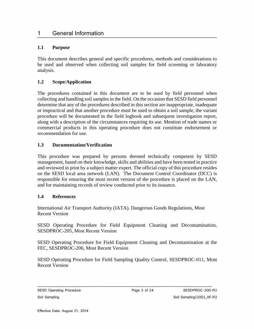
______________________________________________________________________________________ SESD Operating Procedure Page 5 of 24 SESDPROC-300-R3 Soil Sampling Soil Sampling(300)_AF.R3 Effective Date: August 21, 2014
1 General Information 1.1 Purpose
This document describes general and specific procedures, methods and considerations to
be used and observed when collecting soil samples for field screening or laboratory
analysis.
1.2 Scope/Application
The procedures contained in this document are to be used by field personnel when
collecting and handling soil samples in the field. On the occasion that SESD field personnel
determine that any of the procedures described in this section are inappropriate, inadequate
or impractical and that another procedure must be used to obtain a soil sample, the variant
procedure will be documented in the field logbook and subsequent investigation report,
along with a description of the circumstances requiring its use. Mention of trade names or
commercial products in this operating procedure does not constitute endorsement or
recommendation for use.
1.3 Documentation/Verification
This procedure was prepared by persons deemed technically competent by SESD
management, based on their knowledge, skills and abilities and have been tested in practice
and reviewed in print by a subject matter expert. The official copy of this procedure resides
on the SESD local area network (LAN). The Document Control Coordinator (DCC) is
responsible for ensuring the most recent version of the procedure is placed on the LAN,
and for maintaining records of review conducted prior to its issuance.
1.4 References
International Air Transport Authority (IATA). Dangerous Goods Regulations, Most
Recent Version
SESD Operating Procedure for Field Equipment Cleaning and Decontamination,
SESDPROC-205, Most Recent Version
SESD Operating Procedure for Field Equipment Cleaning and Decontamination at the
FEC, SESDPROC-206, Most Recent Version
SESD Operating Procedure for Field Sampling Quality Control, SESDPROC-011, Most
Recent Version
COPY
______________________________________________________________________________________ SESD Operating Procedure Page 6 of 24 SESDPROC-300-R3 Soil Sampling Soil Sampling(300)_AF.R3 Effective Date: August 21, 2014
SESD Operating Procedure for Field X-Ray Fluorescence (XRF) Measurement,
SESDPROC-107, Most Recent Version
SESD Operating Procedure for Logbooks, SESDPROC-010, Most Recent Version
SESD Operating Procedure for Sample and Evidence Management, SESDPROC-005,
Most Recent Version
Title 49 Code of Federal Regulations, Pts. 171 to 179, Most Recent Version
US EPA Test Methods for Evaluating Solid Waste, Physical/Chemical Methods SW-846,
Most Recent Version (Method 5035)
US EPA. Safety, Health and Environmental Management Program (SHEMP) Procedures
and Policy Manual. Region 4 SESD, Athens, GA, Most Recent Version
1.5 General Precautions
1.5.1 Safety
Proper safety precautions must be observed when collecting soil samples. Refer to
the SESD Safety, Health and Environmental Management Program (SHEMP)
Procedures and Policy Manual and any pertinent site-specific Health and Safety
Plans (HASP) for guidelines on safety precautions. These guidelines, however,
should only be used to complement the judgment of an experienced professional.
The reader should address chemicals that pose specific toxicity or safety concerns
and follow any other relevant requirements, as appropriate.
1.5.2 Procedural Precautions
The following precautions should be considered when collecting soil samples:
Special care must be taken not to contaminate samples. This includes storing
samples in a secure location to preclude conditions which could alter the
properties of the sample. Samples shall be custody sealed during long-term
storage or shipment.
Collected samples are in the custody of the sampler or sample custodian until
the samples are relinquished to another party.
If samples are transported by the sampler, they will remain under his/her
custody or be secured until they are relinquished.
Shipped samples shall conform to all U.S. Department of Transportation
(DOT) rules of shipment found in Title 49 of the Code of Federal Regulations
(49 CFR parts 171 to 179), and/or International Air Transportation Association
COPY
______________________________________________________________________________________ SESD Operating Procedure Page 7 of 24 SESDPROC-300-R3 Soil Sampling Soil Sampling(300)_AF.R3 Effective Date: August 21, 2014
(IATA) hazardous materials shipping requirements found in the current edition
of IATA’s Dangerous Goods Regulations.
Documentation of field sampling is done in a bound logbook.
Chain-of-custody documents shall be filled out and remain with the samples
until custody is relinquished.
All shipping documents, such as air bills, bills of lading, etc., shall be retained
by the project leader in the project files.
Sampling in landscaped areas: Cuttings should be placed on plastic sheeting
and returned to the borehole upon completion of the sample collection. Any
‘turf plug’ generated during the sampling process should be returned to the
borehole.
Sampling in non-landscaped areas: Return any unused sample material back
to the auger, drill or push hole from which the sample was collected.
COPY
______________________________________________________________________________________ SESD Operating Procedure Page 8 of 24 SESDPROC-300-R3 Soil Sampling Soil Sampling(300)_AF.R3 Effective Date: August 21, 2014
2 Special Sampling Considerations
2.1 Special Precautions for Trace Contaminant Soil Sampling
A clean pair of new, non-powdered, disposable gloves will be worn each time
a different sample is collected and the gloves should be donned immediately
prior to sampling. The gloves should not come in contact with the media being
sampled and should be changed any time during sample collection when their
cleanliness is compromised.
Sample containers with samples suspected of containing high concentrations
of contaminants shall be handled and stored separately.
All background samples shall be segregated from obvious high-concentration
or waste samples. Sample collection activities shall proceed progressively
from the least suspected contaminated area to the most suspected contaminated
area. Samples of waste or highly-contaminated media must not be placed in
the same ice chest as environmental (i.e., containing low contaminant levels)
or background samples.
If possible, one member of the field sampling team should take all the notes
and photographs, fill out tags, etc., while the other member(s) collect the
samples.
Samplers must use new, verified/certified-clean disposable or non-disposable
equipment cleaned according to procedures contained in the SESD Operating
Procedure for Field Equipment Cleaning and Decontamination (SESDPROC-
205), for collection of samples for trace metals or organic compound analyses.
2.2 Sample Homogenization
1. If sub-sampling of the primary sample is to be performed in the laboratory,
transfer the entire primary sample directly into an appropriate, labeled sample
container(s). Proceed to step 4.
2. If sub-sampling the primary sample in the field or compositing multiple
primary samples in the field, place the sample into a glass or stainless steel
homogenization container and mix thoroughly. Each aliquot of a composite
sample should be of the same approximate volume.
3. All soil samples must be thoroughly mixed to ensure that the sample is as
representative as possible of the sample media. Samples for VOC analysis are
not homogenized. The most common method of mixing is referred to as
quartering. The quartering procedure should be performed as follows:
COPY
______________________________________________________________________________________ SESD Operating Procedure Page 9 of 24 SESDPROC-300-R3 Soil Sampling Soil Sampling(300)_AF.R3 Effective Date: August 21, 2014
The material in the sample pan should be divided into quarters and each
quarter should be mixed individually.
Two quarters should then be mixed to form halves.
The two halves should be mixed to form a homogenous matrix.
This procedure should be repeated several times until the sample is
adequately mixed. If round bowls are used for sample mixing, adequate
mixing is achieved by stirring the material in a circular fashion,
reversing direction, and occasionally turning the material over.
4. Place the sample into an appropriate, labeled container(s) by using the alternate
shoveling method and secure the cap(s) tightly. The alternate shoveling
method involves placing a spoonful of soil in each container in sequence and
repeating until the containers are full or the sample volume has been exhausted.
Threads on the container and lid should be cleaned to ensure a tight seal when
closed.
2.3 Dressing Soil Surfaces
Any time a vertical or near vertical surface is sampled, such as achieved when shovels or
similar devices are used for subsurface sampling, the surface should be dressed (scraped)
to remove smeared soil. This is necessary to minimize the effects of contaminant migration
interferences due to smearing of material from other levels.
2.4 Quality Control
If possible, a control sample should be collected from an area not affected by the possible
contaminants of concern and submitted with the other samples. This control sample should
be collected as close to the sampled area as possible and from the same soil type.
Equipment blanks should be collected if equipment is field cleaned and re-used on-site or
if necessary to document that low-level contaminants were not introduced by sampling
tools. SESD Operating Procedure for Field Sampling Quality Control (SESDPROC-011)
contains other procedures that may be applicable to soil sampling investigations.
2.5 Records
Field notes, recorded in a bound field logbook, as well as chain-of-custody documentation
will be generated as described in the SESD Operating Procedure for Logbooks
(SESDPROC-010) and the SESD Operating Procedure for Sample and Evidence
Management (SESDPROC-005).
COPY
______________________________________________________________________________________ SESD Operating Procedure Page 10 of 24 SESDPROC-300-R3 Soil Sampling Soil Sampling(300)_AF.R3 Effective Date: August 21, 2014
3 Method 5035
The procedures outlined here are summarized from Test Methods for Evaluating Solid
Waste, Physical/Chemical Methods SW-846, Method 5035.
3.1 Soil Samples for Volatile Organic Compounds (VOC) Analysis
If samples are to be analyzed for VOCs, they should be collected in a manner that
minimizes disturbance of the sample. For example, when sampling with an auger
bucket, the sample for VOC analysis should be collected directly from the auger
bucket (preferred) or from minimally disturbed material immediately after an auger
bucket is emptied into the pan. The sample shall be containerized by filling an En
Core® Sampler or other Method 5035 compatible container. Samples for VOC
analysis are not homogenized. Preservatives may be required for some samples
with certain variations of Method 5035. Consult the method or the principal
analytical chemist to determine if preservatives are necessary.
3.2 Soil Sampling (Method 5035)
The following sampling protocol is recommended for site investigators assessing
the extent of VOCs in soils at a project site. Because of the large number of options
available, careful coordination between field and laboratory personnel is needed.
The specific sampling containers and sampling tools required will depend upon the
detection levels and intended data use. Once this information has been established,
selection of the appropriate sampling procedure and preservation method best
applicable to the investigation can be made.
3.2.1 Equipment
Soil for VOC analyses may be retrieved using any of the SESD soil sampling
methods described in Sections 4 through 8 of this procedure. Once the soil has
been obtained, the En Core® Sampler, syringes, stainless steel spatula, standard 2-
oz. soil VOC container, or pre-prepared 40 mL vials may be used/required for sub-
sampling. The specific sample containers and the sampling tools required will
depend upon the data quality objectives established for the site or sampling
investigation. The various sub-sampling methods are described below.
3.2.2 Sampling Methodology - Low Concentrations (<200 µg/kg)
When the total VOC concentration in the soil is expected to be less than 200 µg/kg,
the samples may be collected directly with the En Core® Sampler or syringe. If
using the syringes, the sample must be placed in the sample container (40 mL pre-
prepared vial) immediately to reduce volatilization losses. The 40 mL vials should
contain 10 mL of organic-free water for an un-preserved sample or approximately
COPY
______________________________________________________________________________________ SESD Operating Procedure Page 11 of 24 SESDPROC-300-R3 Soil Sampling Soil Sampling(300)_AF.R3 Effective Date: August 21, 2014
10 mL of organic-free water and a preservative. It is recommended that the 40 mL
vials be prepared and weighed by the laboratory (commercial sources are available
which supply preserved and tared vials). When sampling directly with the En
Core® Sampler, the vial must be immediately capped and locked.
A soil sample for VOC analysis may also be collected with conventional sampling
equipment. A sample collected in this fashion must either be placed in the final
sample container (En Core® Sampler or 40 mL pre-prepared vial) immediately or
the sample may be immediately placed into an intermediate sample container with
no head space. If an intermediate container (usually 2-oz. soil jar) is used, the
sample must be transferred to the final sample container (En Core® Sampler or 40
mL pre-prepared vial) as soon as possible, not to exceed 30 minutes.
NOTE: After collection of the sample into either the En Core® Sampler or other
container, the sample must immediately be stored in an ice chest and cooled.
Soil samples may be prepared for shipping and analysis as follows:
En Core® Sampler - the sample shall be capped, locked, and secured in the original
foil bag. All foil bags containing En Core® samplers are then placed in a plastic
bag and sealed with custody tape, if required.
Syringe - Add about 3.7 cc (approximately 5 grams) of sample material to 40-mL
pre-prepared containers. Secure the containers in a plastic bag. Do not use a
custody seal on the container; place the custody seal on the plastic bag. Note: When
using the syringes, it is important that no air is allowed to become trapped behind
the sample prior to extrusion, as this will adversely affect the sample.
Stainless Steel Laboratory Spatulas - Add between 4.5 and 5.5 grams
(approximate) of sample material to 40 mL containers. Secure the containers in a
plastic bag. Do not use a custody seal on the container; place the custody seal on
the plastic bag.
3.2.3 Sampling Methodology - High Concentrations (>200 µg/kg)
Based upon the data quality objectives and the detection level requirements, this
high level method may also be used. Specifically, the sample may be packed into
a single 2-oz. glass container with a screw cap and septum seal. The sample
container must be filled quickly and completely to eliminate head space.
Soils\sediments containing high total VOC concentrations may also be collected as
described in Section 3.2.2, Sampling Methodology - Low Concentrations, and
preserved using 10 mL methanol.
COPY
______________________________________________________________________________________ SESD Operating Procedure Page 12 of 24 SESDPROC-300-R3 Soil Sampling Soil Sampling(300)_AF.R3 Effective Date: August 21, 2014
3.2.4 Special Techniques and Considerations for Method 5035
Effervescence
If low concentration samples effervesce (rapidly form bubbles) from contact with
the acid preservative, then either a test for effervescence must be performed prior
to sampling, or the investigators must be prepared to collect each sample both
preserved or un-preserved, as needed, or all samples must be collected unpreserved.
To check for effervescence, collect a test sample and add to a pre-preserved vial.
If preservation (acidification) of the sample results in effervescence then
preservation by acidification is not acceptable, and the sample must be collected
un-preserved.
If effervescence occurs and only pre-preserved sample vials are available, the
preservative solution may be placed into an appropriate hazardous waste container
and the vials triple rinsed with organic free water. An appropriate amount of
organic free water, equal to the amount of preservative solution, should be placed
into the vial. The sample may then be collected as an un-preserved sample. Note:
the amount of organic free water placed into the vials will have to be accurately
measured.
Sample Size
While this method is an improvement over earlier ones, field investigators must be
aware of an inherent limitation. Because of the extremely small sample size and
the lack of sample mixing, sample representativeness for VOCs may be reduced
compared to samples with larger volumes collected for other constituents. The
sampling design and objectives of the investigation should take this into
consideration.
Holding Times
Sample holding times are specified in the Analytical Support Branch Laboratory
Operations and Quality Assurance Manual (ASBLOQAM), Most Recent Version.
Field investigators should note that the holding time for an un-preserved VOC
soil/sediment sample on ice is 48 hours. Arrangements should be made to ship the
soil/sediment VOC samples to the laboratory by overnight delivery the day they are
collected so the laboratory may preserve and/or analyze the sample within 48 hours
of collection.
COPY
______________________________________________________________________________________ SESD Operating Procedure Page 13 of 24 SESDPROC-300-R3 Soil Sampling Soil Sampling(300)_AF.R3 Effective Date: August 21, 2014
Percent Solids
Samplers must ensure that the laboratory has sufficient material to determine
percent solids in the VOC soil/sediment sample to correct the analytical results to
dry weight. If other analyses requiring percent solids determination are being
performed upon the sample, these results may be used. If not, a separate sample
(minimum of 2 oz.) for percent solids determination will be required. The sample
collected for percent solids may also be used by the laboratory to check for
preservative compatibility.
Safety
Methanol is a toxic and flammable liquid. Therefore, methanol must be handled
with all required safety precautions related to toxic and flammable liquids.
Inhalation of methanol vapors must be avoided. Vials should be opened and closed
quickly during the sample preservation procedure. Methanol must be handled in a
ventilated area. Use protective gloves when handling the methanol vials. Store
methanol away from sources of ignition such as extreme heat or open flames. The
vials of methanol should be stored in a cooler with ice at all times.
Shipping
Methanol and sodium bisulfate are considered dangerous goods, therefore shipment
of samples preserved with these materials by common carrier is regulated by the
U.S. Department of Transportation and the International Air Transport Association
(IATA). The rules of shipment found in Title 49 of the Code of Federal Regulations
(49 CFR parts 171 to 179) and the current edition of the IATA Dangerous Goods
Regulations must be followed when shipping methanol and sodium bisulfate.
Consult the above documents or the carrier for additional information. Shipment of
the quantities of methanol and sodium bisulfate used for sample preservation falls
under the exemption for small quantities.
The summary table on the following page lists the options available for compliance with
SW846 Method 5035. The advantages and disadvantages are noted for each option.
SESD’s goal is to minimize the use of hazardous material (methanol and sodium
bisulfate) and minimize the generation of hazardous waste during sample collection.
COPY
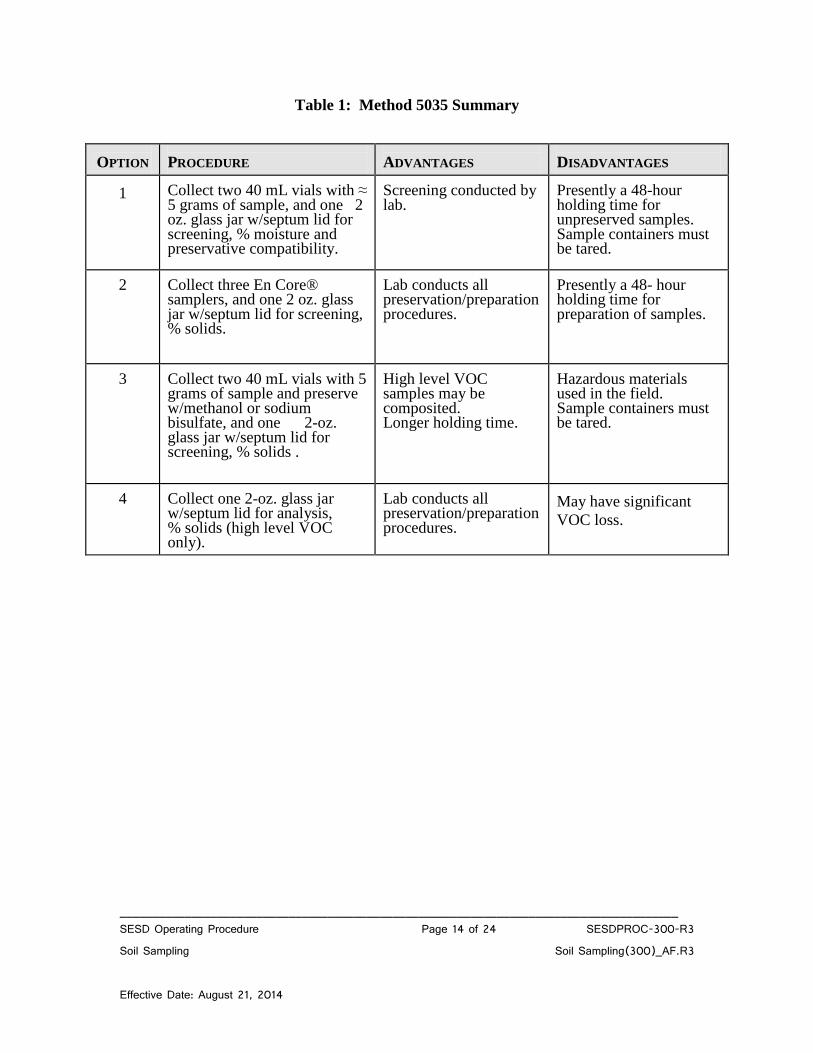
______________________________________________________________________________________ SESD Operating Procedure Page 14 of 24 SESDPROC-300-R3 Soil Sampling Soil Sampling(300)_AF.R3 Effective Date: August 21, 2014
Table 1: Method 5035 Summary
OPTION
PROCEDURE
ADVANTAGES
DISADVANTAGES
1
Collect two 40 mL vials with ≈ 5 grams of sample, and one 2 oz. glass jar w/septum lid for screening, % moisture and preservative compatibility.
Screening conducted by lab.
Presently a 48-hour holding time for unpreserved samples. Sample containers must be tared.
2
Collect three En Core® samplers, and one 2 oz. glass jar w/septum lid for screening, % solids.
Lab conducts all preservation/preparation procedures.
Presently a 48- hour holding time for preparation of samples.
3
Collect two 40 mL vials with 5 grams of sample and preserve w/methanol or sodium bisulfate, and one 2-oz. glass jar w/septum lid for screening, % solids .
High level VOC samples may be composited. Longer holding time.
Hazardous materials used in the field. Sample containers must be tared.
4
Collect one 2-oz. glass jar w/septum lid for analysis, % solids (high level VOC only).
Lab conducts all preservation/preparation procedures.
May have significant
VOC loss.
COPY
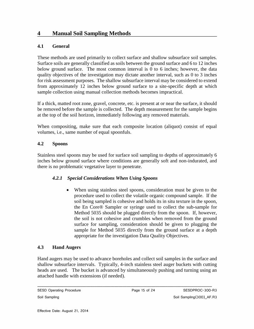
______________________________________________________________________________________ SESD Operating Procedure Page 15 of 24 SESDPROC-300-R3 Soil Sampling Soil Sampling(300)_AF.R3 Effective Date: August 21, 2014
4 Manual Soil Sampling Methods
4.1 General
These methods are used primarily to collect surface and shallow subsurface soil samples.
Surface soils are generally classified as soils between the ground surface and 6 to 12 inches
below ground surface. The most common interval is 0 to 6 inches; however, the data
quality objectives of the investigation may dictate another interval, such as 0 to 3 inches
for risk assessment purposes. The shallow subsurface interval may be considered to extend
from approximately 12 inches below ground surface to a site-specific depth at which
sample collection using manual collection methods becomes impractical.
If a thick, matted root zone, gravel, concrete, etc. is present at or near the surface, it should
be removed before the sample is collected. The depth measurement for the sample begins
at the top of the soil horizon, immediately following any removed materials.
When compositing, make sure that each composite location (aliquot) consist of equal
volumes, i.e., same number of equal spoonfuls.
4.2 Spoons
Stainless steel spoons may be used for surface soil sampling to depths of approximately 6
inches below ground surface where conditions are generally soft and non-indurated, and
there is no problematic vegetative layer to penetrate.
4.2.1 Special Considerations When Using Spoons
When using stainless steel spoons, consideration must be given to the
procedure used to collect the volatile organic compound sample. If the
soil being sampled is cohesive and holds its in situ texture in the spoon,
the En Core® Sampler or syringe used to collect the sub-sample for
Method 5035 should be plugged directly from the spoon. If, however,
the soil is not cohesive and crumbles when removed from the ground
surface for sampling, consideration should be given to plugging the
sample for Method 5035 directly from the ground surface at a depth
appropriate for the investigation Data Quality Objectives.
4.3 Hand Augers
Hand augers may be used to advance boreholes and collect soil samples in the surface and
shallow subsurface intervals. Typically, 4-inch stainless steel auger buckets with cutting
heads are used. The bucket is advanced by simultaneously pushing and turning using an
attached handle with extensions (if needed).
COPY
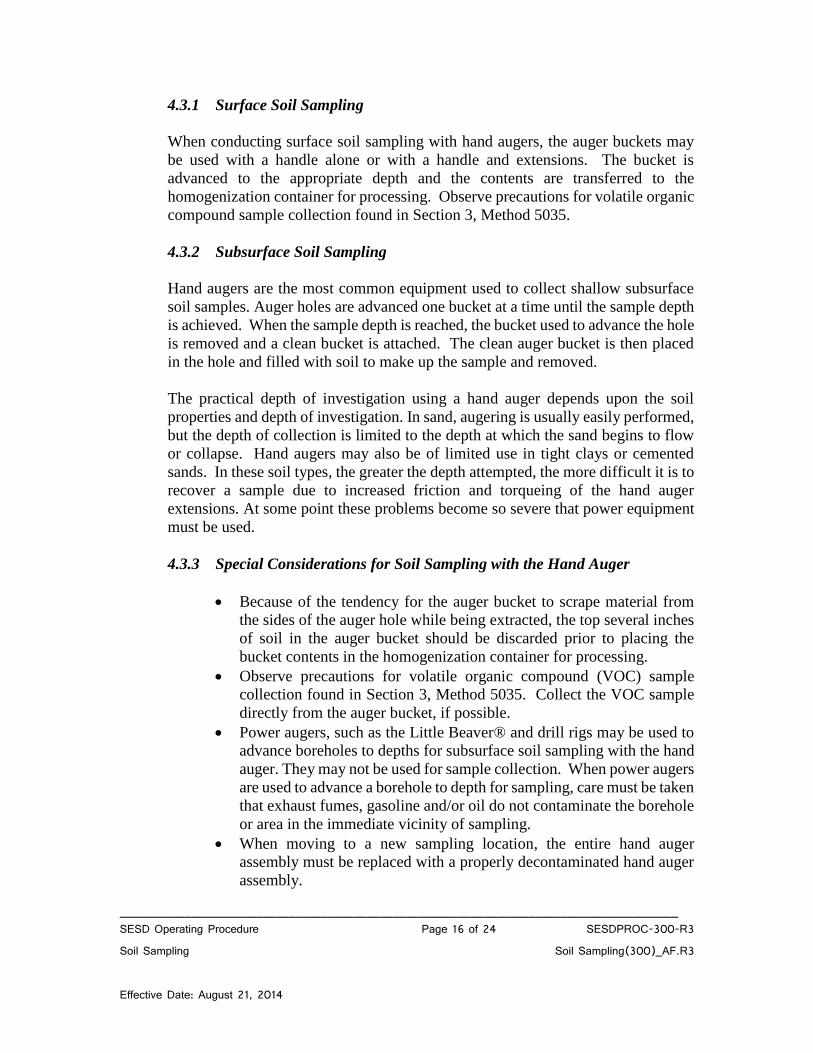
______________________________________________________________________________________ SESD Operating Procedure Page 16 of 24 SESDPROC-300-R3 Soil Sampling Soil Sampling(300)_AF.R3 Effective Date: August 21, 2014
4.3.1 Surface Soil Sampling
When conducting surface soil sampling with hand augers, the auger buckets may
be used with a handle alone or with a handle and extensions. The bucket is
advanced to the appropriate depth and the contents are transferred to the
homogenization container for processing. Observe precautions for volatile organic
compound sample collection found in Section 3, Method 5035.
4.3.2 Subsurface Soil Sampling
Hand augers are the most common equipment used to collect shallow subsurface
soil samples. Auger holes are advanced one bucket at a time until the sample depth
is achieved. When the sample depth is reached, the bucket used to advance the hole
is removed and a clean bucket is attached. The clean auger bucket is then placed
in the hole and filled with soil to make up the sample and removed.
The practical depth of investigation using a hand auger depends upon the soil
properties and depth of investigation. In sand, augering is usually easily performed,
but the depth of collection is limited to the depth at which the sand begins to flow
or collapse. Hand augers may also be of limited use in tight clays or cemented
sands. In these soil types, the greater the depth attempted, the more difficult it is to
recover a sample due to increased friction and torqueing of the hand auger
extensions. At some point these problems become so severe that power equipment
must be used.
4.3.3 Special Considerations for Soil Sampling with the Hand Auger
Because of the tendency for the auger bucket to scrape material from
the sides of the auger hole while being extracted, the top several inches
of soil in the auger bucket should be discarded prior to placing the
bucket contents in the homogenization container for processing.
Observe precautions for volatile organic compound (VOC) sample
collection found in Section 3, Method 5035. Collect the VOC sample
directly from the auger bucket, if possible.
Power augers, such as the Little Beaver® and drill rigs may be used to
advance boreholes to depths for subsurface soil sampling with the hand
auger. They may not be used for sample collection. When power augers
are used to advance a borehole to depth for sampling, care must be taken
that exhaust fumes, gasoline and/or oil do not contaminate the borehole
or area in the immediate vicinity of sampling.
When moving to a new sampling location, the entire hand auger
assembly must be replaced with a properly decontaminated hand auger
assembly.
COPY
______________________________________________________________________________________ SESD Operating Procedure Page 17 of 24 SESDPROC-300-R3 Soil Sampling Soil Sampling(300)_AF.R3 Effective Date: August 21, 2014
5 Direct Push Soil Sampling Methods
5.1 General
These methods are used primarily to collect shallow and deep subsurface soil samples.
Three samplers are available for use within the Division’s direct push tooling inventory.
All of the sampling tools involve the collection and retrieval of the soil sample within a
thin-walled liner. The following sections describe each of the specific sampling methods
that can be accomplished using direct push techniques, along with details specific to each
method. While SESD currently uses the sample tooling described, tooling of similar design
and materials is acceptable.
If gravel, concrete, etc. is present at or near the surface, it should be removed before the
sample is collected. The depth measurement for the sample begins at the top of the soil
horizon, immediately following any removed materials. Turf grass is not typically removed
prior to sampling with these devices.
5.2 Large Bore® Soil Sampler
The Large Bore® (LB) sampler is a solid barrel direct push sampler equipped with a piston-
rod point assembly used primarily for collection of depth-discrete subsurface soil samples.
The sample barrel is approximately 30-inches (762 mm) long and has a 1.5-inch (38 mm)
outside diameter. The LB® sampler is capable of recovering a discrete sample core 22
inches x 1.0 inch (559 mm x 25 mm) contained inside a removable liner. The resultant
sample volume is a maximum of 283 mL.
After the LB® sample barrel is equipped with the cutting shoe and liner, the piston-rod
point assembly is inserted, along with the drive head and piston stop assembly. The
assembled sampler is driven to the desired sampling depth, at which time the piston stop
pin is removed, freeing the push point. The LB® sampler is then pushed into the soil a
distance equal to the length of the LB® sample barrel. The probe rod string, with the LB®
sampler attached, is then removed from the subsurface. After retrieval, the LB® sampler
is then removed from the probe rod string. The drive head is then removed to allow
removal of the liner and soil sample.
5.3 Macro-Core® Soil Sampler
The Macro-Core® (MC) sampler is a solid barrel direct push sampler equipped with a
piston-rod point assembly used primarily for collection of either continuous or depth-
discrete subsurface soil samples. Although other lengths are available, the standard MC®
sampler has an assembled length of approximately 52 inches (1321 mm) with an outside
diameter of 2.2 inches (56 mm). The MC® sampler is capable of recovering a discrete
sample core 45 inches x 1.5 inches (1143 mm x 38 mm) contained inside a removable liner.
The resultant sample volume is a maximum of 1300 mL. The MC® sampler may be used
COPY
______________________________________________________________________________________ SESD Operating Procedure Page 18 of 24 SESDPROC-300-R3 Soil Sampling Soil Sampling(300)_AF.R3 Effective Date: August 21, 2014
in either an open-tube or closed-point configuration. Although the MC® sampler can be
used as an open-barrel sampler, in SESD usage, the piston point is always used to prevent
the collection of slough from the borehole sides.
5.4 Dual Tube Soil Sampling System
The Dual Tube 21 soil sampling system is a direct push system for collecting continuous
core samples of unconsolidated materials from within a sealed outer casing of 2.125-inch
(54 mm) OD probe rod. The samples are collected within a liner that is threaded onto the
leading end of a string of 1.0-inch diameter probe rod. Collected samples have a volume
of up to 800 mL in the form of a 1.125-inch x 48-inch (29 mm x 1219 mm) core. Use of
this method allows for collection of continuous core inside a cased hole, minimizing or
preventing cross-contamination between different intervals during sample collection. The
outer casing is advanced, one core length at a time, with only the inner probe rod and core
being removed and replaced between samples. If the sampling zone of interest begins at
some depth below ground surface, a solid drive tip must be used to drive the dual tube
assembly and core to its initial sample depth.
5.5 Special Considerations When Using Direct Push Sampling Methods
Liner Use and Material Selection – Direct Push Soil Samples are collected
within a liner to facilitate removal of sample material from the sample barrel.
The liners may only be available in a limited number of materials for a given
sample tool, although overall, liners are available in brass, stainless steel,
cellulose acetate butyrate (CAB), polyethylene terepthalate glycol (PETG),
polyvinyl chloride (PVC) and Teflon®. For most SESD investigations, the
standard polymer liner material for a sampling tool will be acceptable. When
the study objectives require very low reporting levels or unusual contaminants
of concern, the use of more inert liner materials such as Teflon® or stainless
steel may be necessary.
Sample Orientation – When the liners and associated sample are removed from
the sample tubes, it is important to maintain the proper orientation of the
sample. This is particularly important when multiple sample depths are
collected from the same push. It is also important to maintain proper
orientation to define precisely the depth at which an aliquot was collected.
Maintaining proper orientation is typically accomplished using vinyl end caps.
Convention is to place red caps on the top of the liner and black caps on the
bottom to maintain proper sample orientation. Orientation can also be
indicated by marking on the exterior of the liner with a permanent marker.
Core Catchers – Occasionally the material being sampled lacks cohesiveness
and is subject to crumbling and falling out of the sample liner. In cases such
as these, the use of core catchers on the leading end of the sampler may help
COPY
______________________________________________________________________________________ SESD Operating Procedure Page 19 of 24 SESDPROC-300-R3 Soil Sampling Soil Sampling(300)_AF.R3 Effective Date: August 21, 2014
retain the sample until it is retrieved to the surface. Core catchers may only be
available in specific materials and should be evaluated for suitability.
However, given the limited sample contact that core-catchers have with the
sample material, most standard core-catchers available for a tool system will
be acceptable.
Decontamination – The cutting shoe and piston rod point are to be
decontaminated between each sample, using the procedures specified for the
collection of trace organic and inorganic compounds found in Field Equipment
and Decontamination – SESDPROC-205, most recent version. Within a
borehole, the sample barrel, rods, and drive head may be subjected to an
abbreviated cleaning to remove obvious and loose material, but must be
cleaned between boreholes using the procedures specified for downhole
drilling equipment in Field Equipment and Decontamination – SESDPROC-
205, most recent version.
Decommissioning – Boreholes must be decommissioned after the completion
of sampling. Boreholes less than 10 feet deep that remain open and do not
approach the water table may be decommissioned by pouring 30% solids
bentonite grout from the surface or pouring bentonite pellets from the surface,
hydrating the pellets in lifts. Boreholes deeper than 10 feet, or any borehole
that intercepts groundwater, must be decommissioned by pressure grouting
with 30% solids bentonite grout, either through a re-entry tool string or through
tremie pipe introduced to within several feet of the borehole bottom.
VOC Sample Collection – Observe precautions for volatile organic compound
sample collection found in Section 3 of this procedure.
COPY
______________________________________________________________________________________ SESD Operating Procedure Page 20 of 24 SESDPROC-300-R3 Soil Sampling Soil Sampling(300)_AF.R3 Effective Date: August 21, 2014
6 Split Spoon/Drill Rig Methods
6.1 General
Split spoon sampling methods are used primarily to collect shallow and deep subsurface
soil samples. All split spoon samplers, regardless of size, are basically split cylindrical
barrels that are threaded on each end. The leading end is held together with a beveled
threaded collar that functions as a cutting shoe. The other end is held together with a
threaded collar that serves as the sub used to attach the spoon to the string of drill rod. Two
basic methods are available for use, including the smaller diameter standard split spoon,
driven with the drill rig safety hammer, and the larger diameter continuous split spoon,
advanced inside and slightly ahead of the lead auger during hollow stem auger drilling.
The following sections describe each of the specific sampling methods, along with details
specific to each method.
If gravel, concrete, etc. is present at or near the surface, it should be removed before the
sample is collected. The depth measurement for the sample begins at the top of the soil
horizon, immediately following any removed materials. Turf grass is not typically removed
prior to sampling with these devices.
6.2 Standard Split Spoon
A drill rig is used to advance a borehole to the target depth. The drill string is then removed
and a standard split spoon is attached to a string of drill rod. Split spoons used for soil
sampling must be constructed of stainless steel and are typically 2.0-inches OD (1.5-inches
ID) and 18-inches to 24-inches in length. Other diameters and lengths are common and
may be used if constructed of the proper material. After the spoon is attached to the string
of drill rod, it is lowered into the borehole. The safety hammer is then used to drive the
split spoon into the soil at the bottom of the borehole. After the split spoon has been driven
into the soil, filling the spoon, it is retrieved to the surface, where it is removed from the
drill rod string and opened for sample acquisition.
6.3 Continuous Split Spoon
The continuous split spoon is a large diameter split spoon that is advanced into the soil
column inside a hollow stem auger. Continuous split spoons are typically 3 to 5 inches in
diameter and either 5 feet or 10 feet in length, although the 5-foot long samplers are most
common. After the auger string has been advanced into the soil column a distance equal
to the length of the sampler being used it is returned to the surface. The sampler is removed
from inside the hollow stem auger and the threaded collars are removed. The split spoon
is then opened for sampling.
COPY

______________________________________________________________________________________ SESD Operating Procedure Page 21 of 24 SESDPROC-300-R3 Soil Sampling Soil Sampling(300)_AF.R3 Effective Date: August 21, 2014
6.4 Special Considerations When Using Split Spoon Sampling Methods
Always discard the top several inches of material in the spoon before removing
any portion for sampling. This material normally consists of borehole wall
material that has sloughed off of the borehole wall after removal of the drill
string prior to and during inserting the split spoon.
Observe precautions for volatile organic compound sample collection found in
Section 3, Method 5035.
COPY
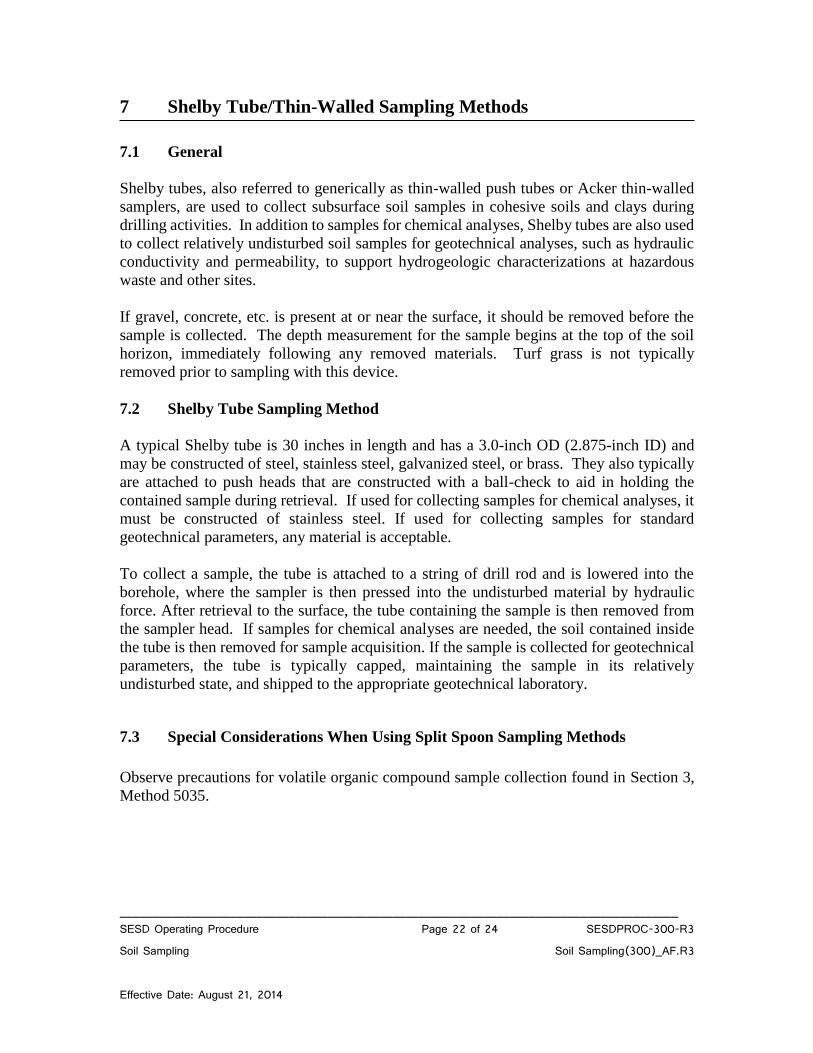
______________________________________________________________________________________ SESD Operating Procedure Page 22 of 24 SESDPROC-300-R3 Soil Sampling Soil Sampling(300)_AF.R3 Effective Date: August 21, 2014
7 Shelby Tube/Thin-Walled Sampling Methods 7.1 General
Shelby tubes, also referred to generically as thin-walled push tubes or Acker thin-walled
samplers, are used to collect subsurface soil samples in cohesive soils and clays during
drilling activities. In addition to samples for chemical analyses, Shelby tubes are also used
to collect relatively undisturbed soil samples for geotechnical analyses, such as hydraulic
conductivity and permeability, to support hydrogeologic characterizations at hazardous
waste and other sites.
If gravel, concrete, etc. is present at or near the surface, it should be removed before the
sample is collected. The depth measurement for the sample begins at the top of the soil
horizon, immediately following any removed materials. Turf grass is not typically
removed prior to sampling with this device.
7.2 Shelby Tube Sampling Method
A typical Shelby tube is 30 inches in length and has a 3.0-inch OD (2.875-inch ID) and
may be constructed of steel, stainless steel, galvanized steel, or brass. They also typically
are attached to push heads that are constructed with a ball-check to aid in holding the
contained sample during retrieval. If used for collecting samples for chemical analyses, it
must be constructed of stainless steel. If used for collecting samples for standard
geotechnical parameters, any material is acceptable.
To collect a sample, the tube is attached to a string of drill rod and is lowered into the
borehole, where the sampler is then pressed into the undisturbed material by hydraulic
force. After retrieval to the surface, the tube containing the sample is then removed from
the sampler head. If samples for chemical analyses are needed, the soil contained inside
the tube is then removed for sample acquisition. If the sample is collected for geotechnical
parameters, the tube is typically capped, maintaining the sample in its relatively
undisturbed state, and shipped to the appropriate geotechnical laboratory.
7.3 Special Considerations When Using Split Spoon Sampling Methods
Observe precautions for volatile organic compound sample collection found in Section 3,
Method 5035.
COPY
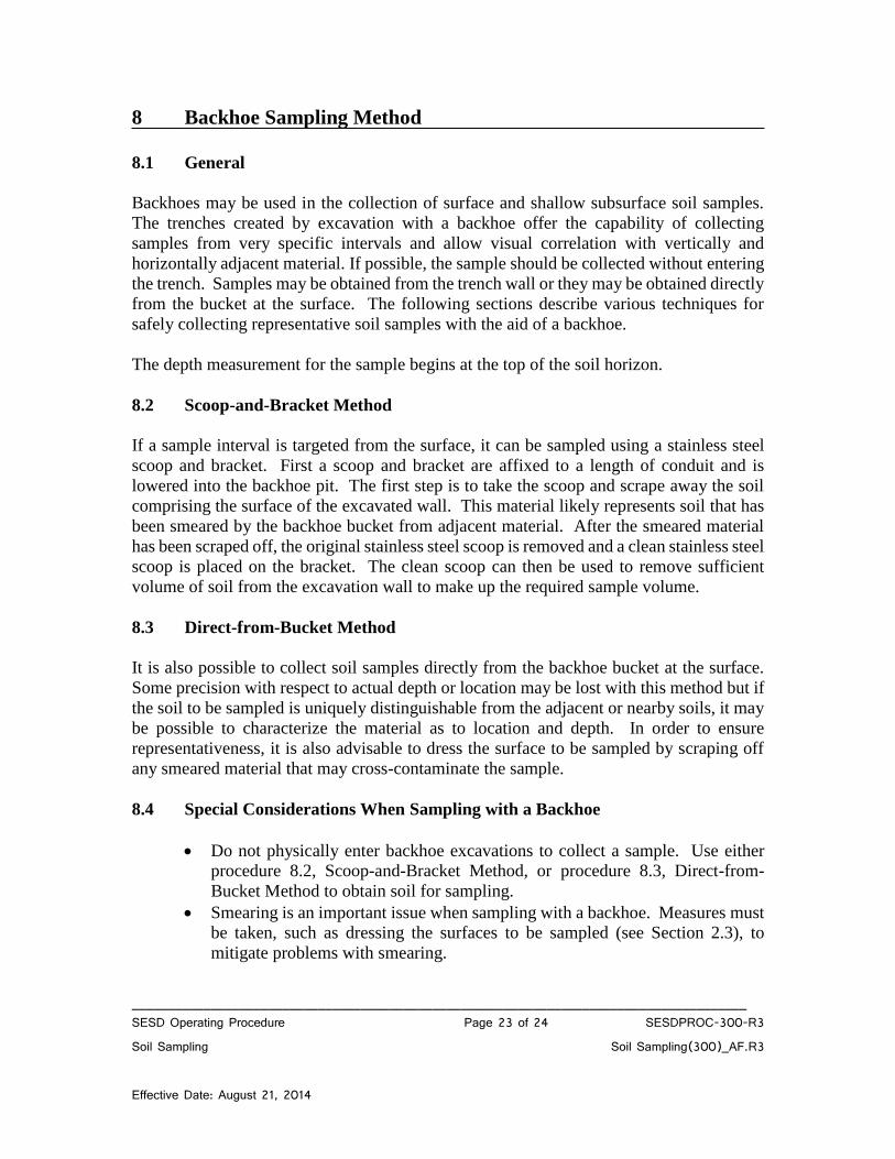
______________________________________________________________________________________ SESD Operating Procedure Page 23 of 24 SESDPROC-300-R3 Soil Sampling Soil Sampling(300)_AF.R3 Effective Date: August 21, 2014
8 Backhoe Sampling Method
8.1 General
Backhoes may be used in the collection of surface and shallow subsurface soil samples.
The trenches created by excavation with a backhoe offer the capability of collecting
samples from very specific intervals and allow visual correlation with vertically and
horizontally adjacent material. If possible, the sample should be collected without entering
the trench. Samples may be obtained from the trench wall or they may be obtained directly
from the bucket at the surface. The following sections describe various techniques for
safely collecting representative soil samples with the aid of a backhoe.
The depth measurement for the sample begins at the top of the soil horizon.
8.2 Scoop-and-Bracket Method
If a sample interval is targeted from the surface, it can be sampled using a stainless steel
scoop and bracket. First a scoop and bracket are affixed to a length of conduit and is
lowered into the backhoe pit. The first step is to take the scoop and scrape away the soil
comprising the surface of the excavated wall. This material likely represents soil that has
been smeared by the backhoe bucket from adjacent material. After the smeared material
has been scraped off, the original stainless steel scoop is removed and a clean stainless steel
scoop is placed on the bracket. The clean scoop can then be used to remove sufficient
volume of soil from the excavation wall to make up the required sample volume.
8.3 Direct-from-Bucket Method
It is also possible to collect soil samples directly from the backhoe bucket at the surface.
Some precision with respect to actual depth or location may be lost with this method but if
the soil to be sampled is uniquely distinguishable from the adjacent or nearby soils, it may
be possible to characterize the material as to location and depth. In order to ensure
representativeness, it is also advisable to dress the surface to be sampled by scraping off
any smeared material that may cross-contaminate the sample.
8.4 Special Considerations When Sampling with a Backhoe
Do not physically enter backhoe excavations to collect a sample. Use either
procedure 8.2, Scoop-and-Bracket Method, or procedure 8.3, Direct-from-
Bucket Method to obtain soil for sampling.
Smearing is an important issue when sampling with a backhoe. Measures must
be taken, such as dressing the surfaces to be sampled (see Section 2.3), to
mitigate problems with smearing.
COPY

______________________________________________________________________________________ SESD Operating Procedure Page 24 of 24 SESDPROC-300-R3 Soil Sampling Soil Sampling(300)_AF.R3 Effective Date: August 21, 2014
Paint, grease and rust must be removed and the bucket decontaminated prior to
sample collection.
Observe precautions for volatile organic compound sample collection found in
Section 3, Method 5035.
COPY
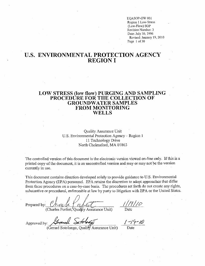
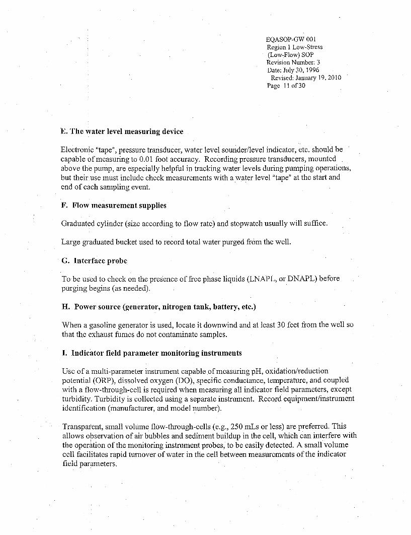
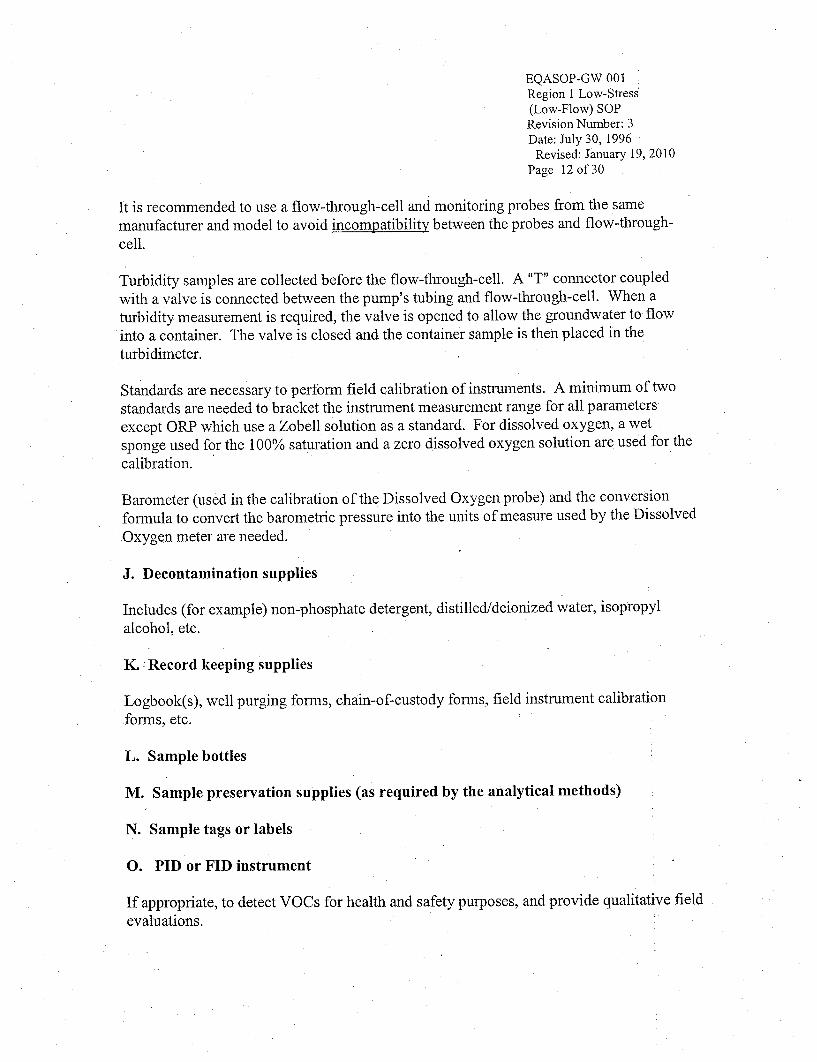
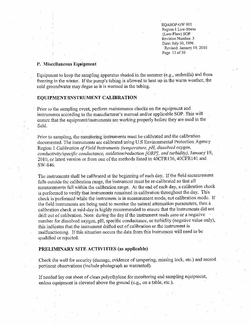
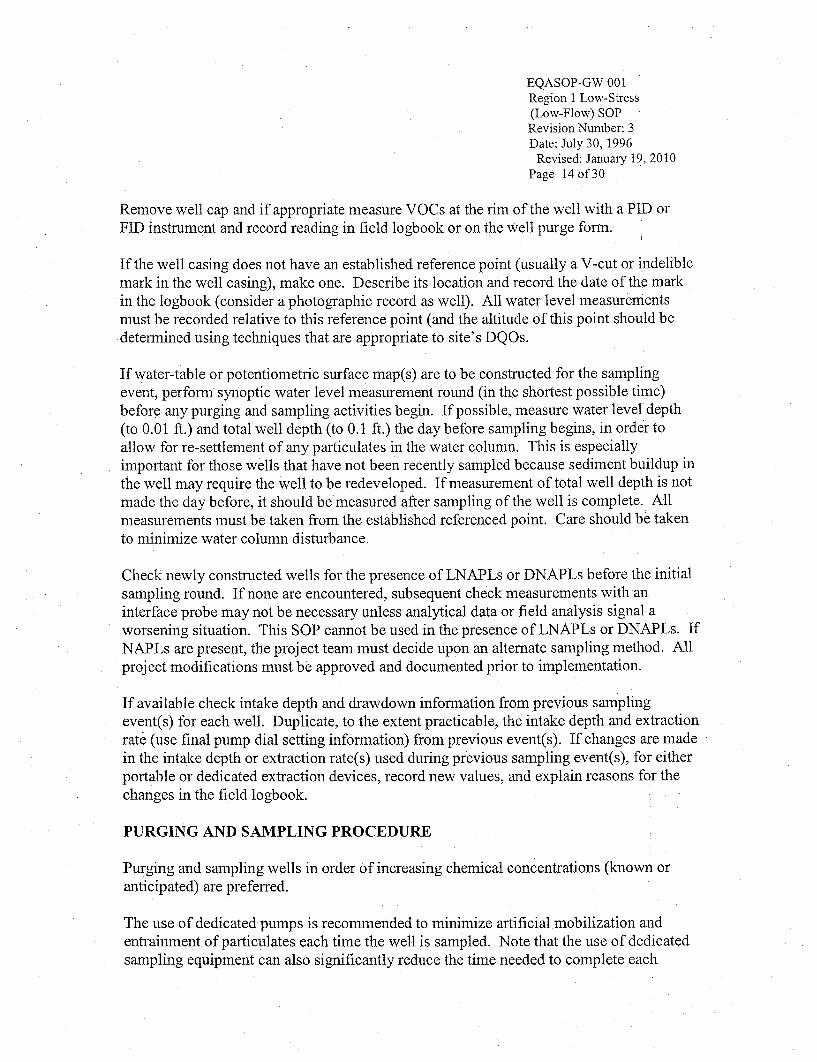
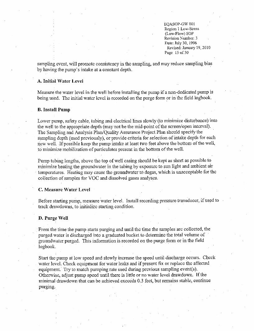
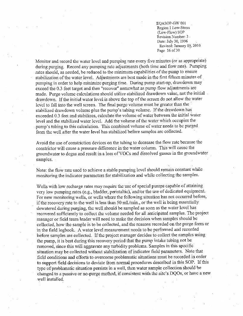
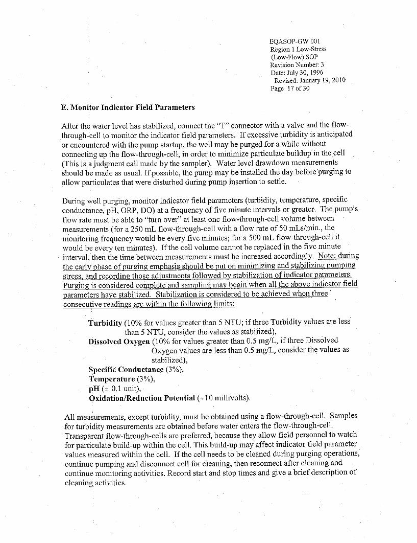
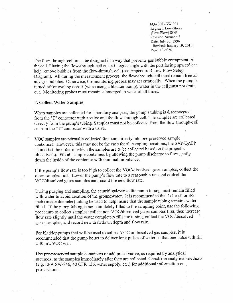

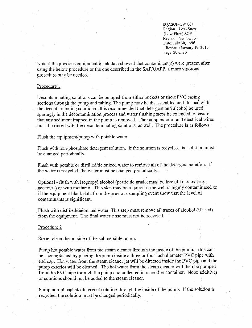
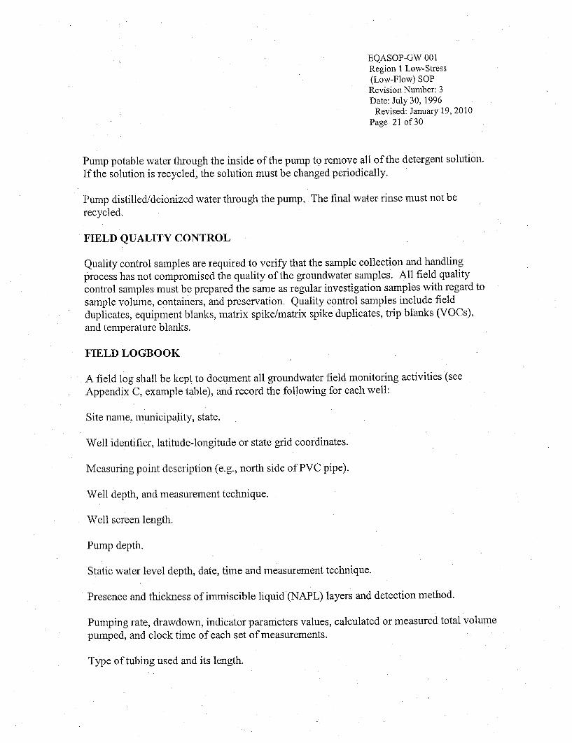
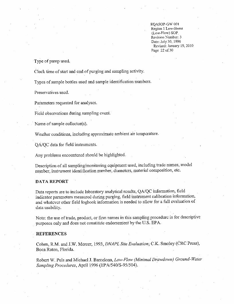
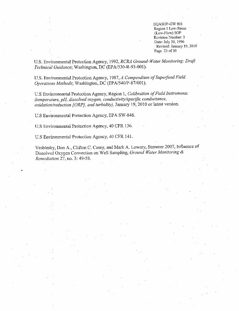
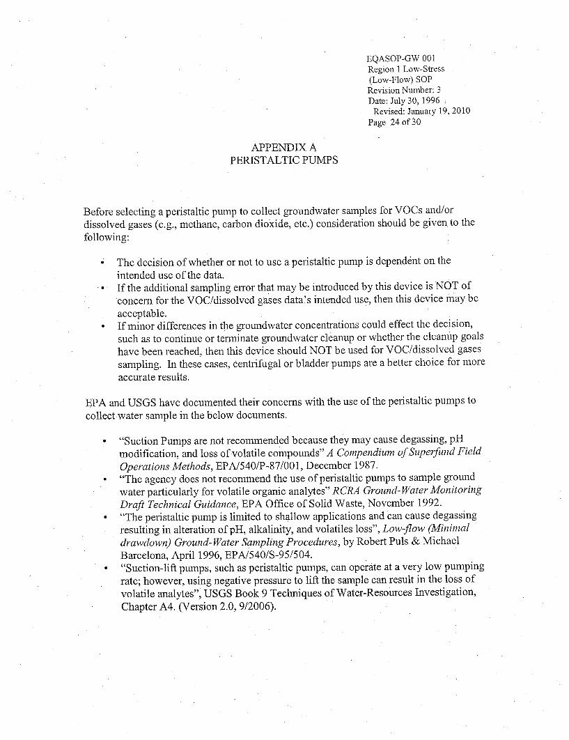
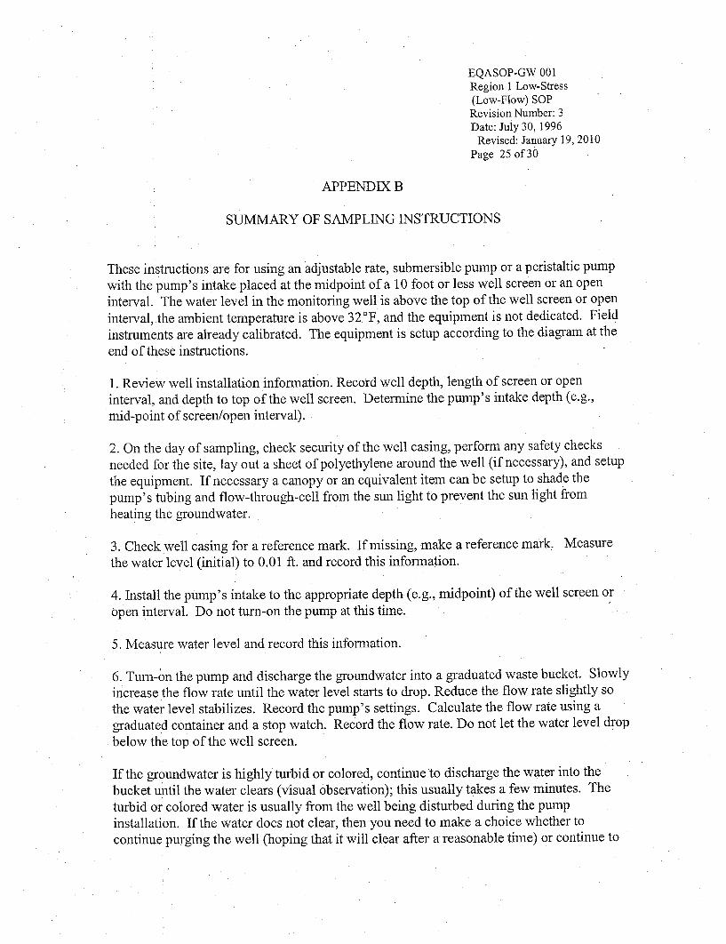
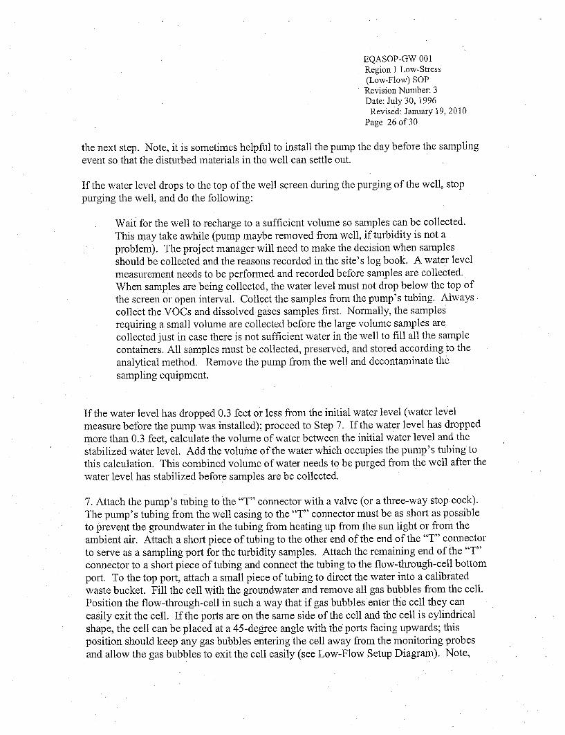
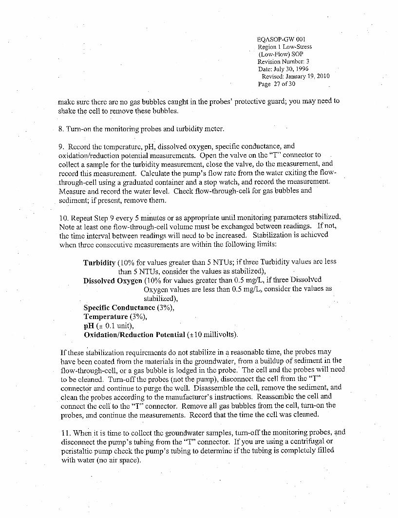
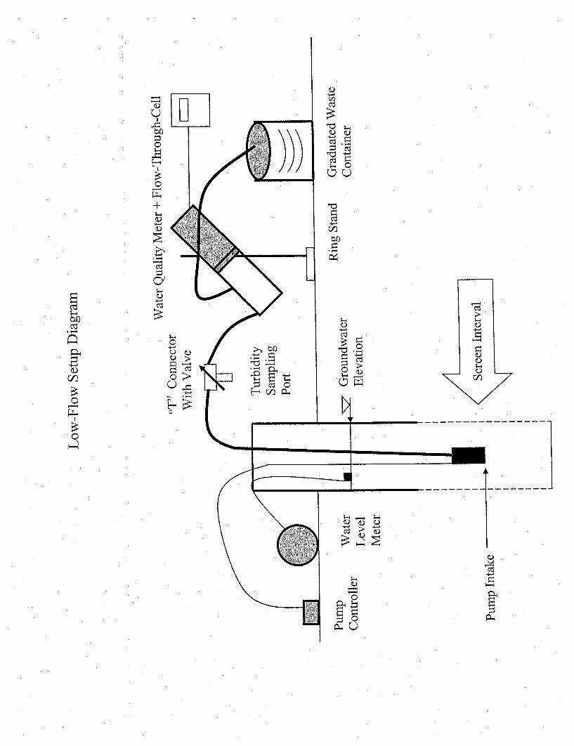
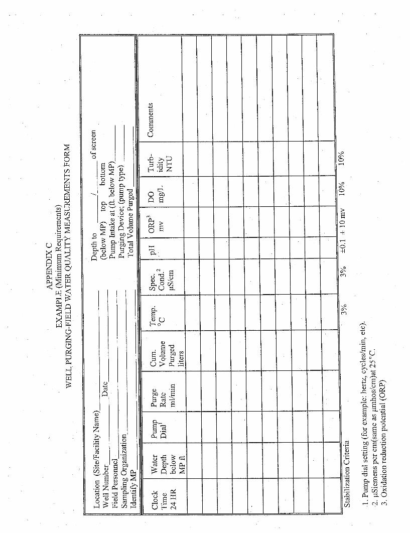
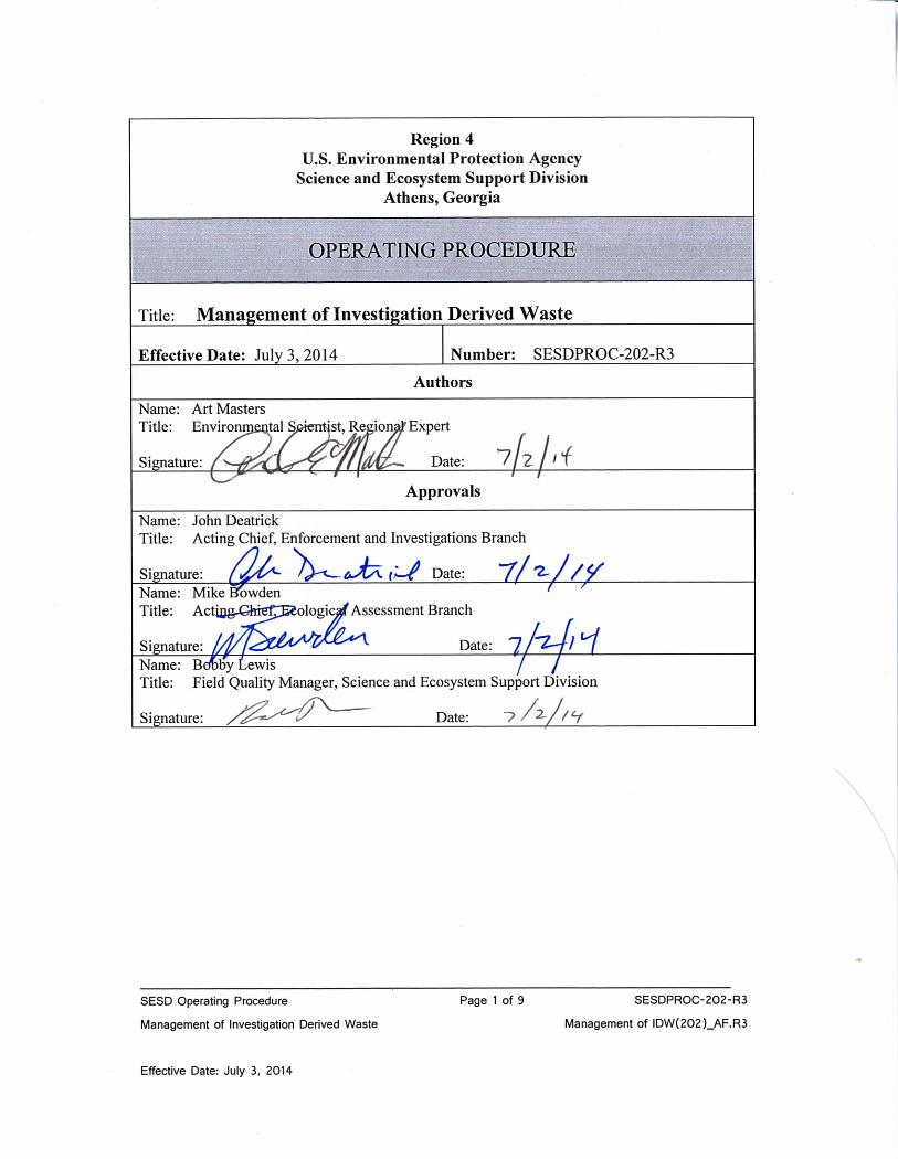
COPY
______________________________________________________________________________________ SESD Operating Procedure Page 2 of 9 SESDPROC-202-R3 Management of Investigation Derived Waste Management of IDW(202)_AF.R3 Effective Date: July 3, 2014
Revision History
The top row of this table shows the most recent changes to this controlled document. For
previous revision history information, archived versions of this document are maintained
by the SESD Document Control Coordinator on the SESD local area network (LAN).
History Effective Date
SESDPROC-202-R3, Management of Investigation Derived
Waste, replaces SESDPROC-202-R2.
General: Corrected typographical, grammatical and/or editorial errors.
Cover Page: The Enforcement and Investigations Branch Chief was
changed from Archie Lee to Acting Chief John Deatrick. The Ecological
Assessment Branch Chief was changed from Bill Cosgrove to Acting Chief
Mike Bowden. The FQM was changed from Liza Montalvo to Bobby Lewis.
Revision History: Changes were made to reflect the current practice of only
including the most recent changes in the revision history.
July 3, 2014
SESDPROC-202-R2, Management of Investigation Derived
Waste, replaces SESDPROC-202-R1.
October 15, 2010
SESDPROC-202-R1, Management of Investigation Derived
Waste, replaces SESDPROC-202-R0.
November 1, 2007
SESDPROC-202-R0, Management of Investigation Derived
Waste, Original Issue
February 05, 2007
COPY
______________________________________________________________________________________ SESD Operating Procedure Page 3 of 9 SESDPROC-202-R3 Management of Investigation Derived Waste Management of IDW(202)_AF.R3 Effective Date: July 3, 2014
TABLE OF CONTENTS
1 General Information ................................................................................................. 4
1.1 Purpose............................................................................................................... 4
1.2 Scope/Application ............................................................................................. 4
1.3 Documentation/Verification ............................................................................. 4
1.4 References .......................................................................................................... 4
1.5 General Precautions.......................................................................................... 5
1.5.1 Safety ................................................................................................................ 5
1.5.2 Procedural Precautions ................................................................................... 5
2 Types of Investigation Derived Waste .................................................................... 6
3 Management of Non-Hazardous IDW .................................................................... 7
4 Management of Hazardous IDW............................................................................. 8
TABLES
Table 1: Disposal of IDW ................................................................................................ 9
COPY
______________________________________________________________________________________ SESD Operating Procedure Page 4 of 9 SESDPROC-202-R3 Management of Investigation Derived Waste Management of IDW(202)_AF.R3 Effective Date: July 3, 2014
Contents
1 General Information
1.1 Purpose
This document describes general and specific procedures and considerations to be used
and observed when managing investigation derived waste (IDW) generated during the
course of hazardous waste site investigations.
1.2 Scope/Application
The procedures and management options for the different categories of IDW described in
this document are to be used by SESD field personnel to manage IDW generated during
site investigations. On the occasion that SESD field personnel determine that any of the
procedures described in this section are inappropriate, inadequate or impractical and that
another procedure must be used to manage IDW generated at a particular site, the variant
procedure will be documented in the field logbook, along with a description of the
circumstances requiring its use. Mention of trade names or commercial products does not
constitute endorsement or recommendation for use.
1.3 Documentation/Verification
This procedure was prepared by persons deemed technically competent by SESD
management, based on their knowledge, skills and abilities and have been tested in
practice and reviewed in print by a subject matter expert. The official copy of this
procedure resides on the SESD Local Area Network (LAN). The Document Control
Coordinator (DCC) is responsible for ensuring the most recent version of the procedure is
placed on the LAN and for maintaining records of review conducted prior to its issuance.
1.4 References
SESD Operating Procedure for Field Equipment Cleaning and Decontamination,
SESDPROC-205, Most Recent Version
United States Environmental Protection Agency (US EPA). 2001. Environmental
Investigations Standard Operating Procedures and Quality Assurance Manual. Region 4
Science and Ecosystem Support Division (SESD), Athens, GA
US EPA. Safety, Health and Environmental Management Program Procedures and Policy
Manual. Region 4 SESD, Athens, GA, Most Recent Version
COPY
______________________________________________________________________________________ SESD Operating Procedure Page 5 of 9 SESDPROC-202-R3 Management of Investigation Derived Waste Management of IDW(202)_AF.R3 Effective Date: July 3, 2014
1.5 General Precautions
1.5.1 Safety
Proper safety precautions must be observed when managing IDW. Refer to the
SESD Safety, Health and Environmental Management Program (SHEMP)
Procedures and Policy Manual and any pertinent site-specific Health and Safety
Plans (HASP) for guidelines on safety precautions. These guidelines, however,
should only be used to complement the judgment of an experienced professional.
Address chemicals that pose specific toxicity or safety concerns and follow any
other relevant requirements, as appropriate.
1.5.2 Procedural Precautions
The following precautions should be considered when managing IDW:
Due to time limitations and restrictions posed by RCRA regulations on
storage of hazardous waste, accumulation start dates should be identified
on all drums, buckets or other containers used to hold IDW so that it can
be managed in a timely manner.
During generation of both non-hazardous and hazardous IDW, keep
hazardous IDW segregated from non-hazardous IDW to minimize the
volume of hazardous IDW that must be properly managed.
COPY
______________________________________________________________________________________ SESD Operating Procedure Page 6 of 9 SESDPROC-202-R3 Management of Investigation Derived Waste Management of IDW(202)_AF.R3 Effective Date: July 3, 2014
2 Types of Investigation Derived Waste
Materials which may become IDW include, but are not limited to:
Personal protective equipment (PPE) - This includes disposable coveralls, gloves,
booties, respirator canisters, splash suits, etc.
Disposable equipment and items - This includes plastic ground and equipment
covers, aluminum foil, conduit pipe, composite liquid waste samplers (COLIWASAs), Teflon® tubing, broken or unused sample containers, sample container boxes, tape, etc.
Soil cuttings from drilling or hand augering.
Drilling mud or water used for mud or water rotary drilling.
Groundwater obtained through well development or well purging.
Cleaning fluids such as spent solvents and wash water.
Packing and shipping materials. Table 1, found at the end of this procedure, lists the types of IDW commonly generated during field investigations and the current disposal practices for these materials.
For the purpose of determining the ultimate disposition of IDW, it is typically
distinguished as being either hazardous or non-hazardous. This determination is based on
either clear regulatory guidance or by subsequent analysis. This determination and
subsequent management is the responsibility of the program site manager.
COPY
______________________________________________________________________________________ SESD Operating Procedure Page 7 of 9 SESDPROC-202-R3 Management of Investigation Derived Waste Management of IDW(202)_AF.R3 Effective Date: July 3, 2014
3 Management of Non-Hazardous IDW
Disposal of non-hazardous IDW should be addressed in the study plan or QAPP for the
investigation. To reduce the volume of any IDW transported back to the Field
Equipment Center (FEC), it may be necessary to compact the waste into a reusable
container, such as a 55-gallon drum.
If the waste is from an active facility, permission should be sought from the operator of
the facility to place the non-hazardous PPE, disposable equipment, and/or
paper/cardboard into the facility’s dumpsters. If necessary, these materials may be placed
into municipal dumpsters, with the permission of the owner. These materials may also be
taken to a nearby permitted landfill. On larger studies, waste hauling services may be
obtained and a dumpster located at the study site.
Disposal of non-hazardous IDW such as drill cuttings, drilling mud, purge or
development water, decontamination wash water, etc., should be specified in the
approved study plan or QAPP. It is recommended that these materials be placed into a
unit with an environmental permit, such as a landfill or sanitary sewer. These materials
must not be placed into dumpsters. If the facility at which the study is being conducted is
active, permission should be sought to place these types of IDW into the facility’s
treatment system. It may be feasible to spread drill cuttings around the borehole, or, if
the well is temporary, to place the cuttings back into the borehole. Non-hazardous
monitoring well purge or development water may also be poured onto the ground down
gradient of the monitoring well when site conditions permit. Purge water from private
potable wells which are in service may be discharged directly onto the ground surface.
The minimum requirements for this subsection are:
Non-hazardous liquid and soil/sediment IDW may be placed on the ground or returned to the source if doing so does not endanger human health or the environment or violate federal or state regulations. Under no circumstances, however, should monitoring well purge water be placed back into the well from which it came.
Soap and water decontamination fluids and rinsates of such cannot be placed in any water bodies and must be collected and returned to the FEC for disposition.
The collection, handling and proposed disposal method must be specified in the approved study plan or QAPP.
COPY
______________________________________________________________________________________ SESD Operating Procedure Page 8 of 9 SESDPROC-202-R3 Management of Investigation Derived Waste Management of IDW(202)_AF.R3 Effective Date: July 3, 2014
4 Management of Hazardous IDW
Disposal of hazardous or suspected hazardous IDW must be specified in the approved study plan or QAPP for the study or investigation. Hazardous IDW must be disposed as specified in USEPA regulations. If appropriate, these wastes may be placed back in an active facility waste treatment system. These wastes may also be disposed in the source area from which they originated if doing so does not endanger human health or the environment. If on-site disposal is not feasible, and if the wastes are suspected to be hazardous, appropriate tests must be conducted to make that determination. If they are determined to be hazardous wastes, they must be properly contained and labeled. They may be stored on the site for a maximum of 90 days before they must be manifested and shipped to a permitted treatment or disposal facility. Generation of hazardous IDW must be anticipated, if possible, to allow arrangements for proper containerization, labeling, transportation and disposal/treatment in accordance with USEPA regulations. The generation of hazardous IDW should be minimized to conserve Division resources. Most routine studies should not produce any hazardous IDW, with the possible exception of spent solvents and, possibly, purged groundwater. The use of solvents during field cleaning of equipment should be minimized by using solvent-free cleaning procedures for routine cleaning and decontamination (see SESD Operating Procedure for Field Equipment Cleaning and Decontamination, SESDPROC-205). If solvents are needed, the volume should be minimized by using only the amount necessary and by capturing the residual solvent separately from the aqueous decontamination fluids (detergent/wash water mixes and water rinses). At a minimum, the requirements of the management of hazardous IDW are as follows:
Spent solvents must be left on-site with the permission of site operator and proper disposal arranged.
All hazardous IDW must be containerized. Proper handling and disposal should be arranged prior to commencement of field activities.
COPY
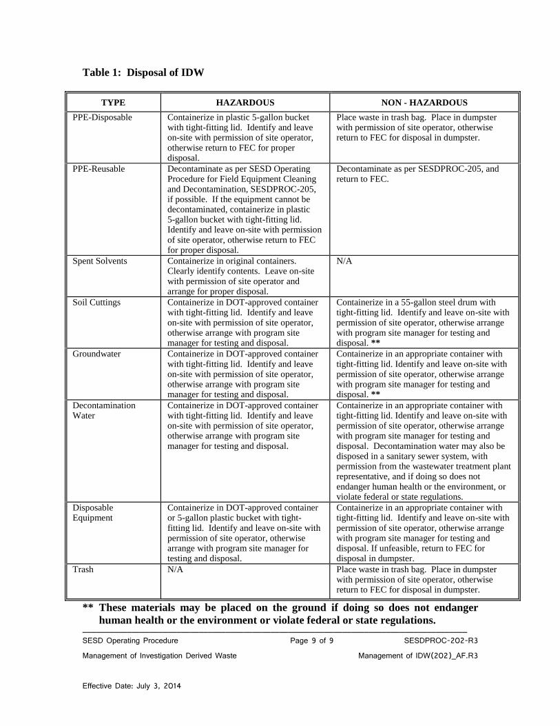
______________________________________________________________________________________ SESD Operating Procedure Page 9 of 9 SESDPROC-202-R3 Management of Investigation Derived Waste Management of IDW(202)_AF.R3 Effective Date: July 3, 2014
Table 1: Disposal of IDW
TYPE HAZARDOUS NON - HAZARDOUS
PPE-Disposable Containerize in plastic 5-gallon bucket with tight-fitting lid. Identify and leave on-site with permission of site operator, otherwise return to FEC for proper disposal.
Place waste in trash bag. Place in dumpster with permission of site operator, otherwise return to FEC for disposal in dumpster.
PPE-Reusable Decontaminate as per SESD Operating Procedure for Field Equipment Cleaning and Decontamination, SESDPROC-205, if possible. If the equipment cannot be decontaminated, containerize in plastic 5-gallon bucket with tight-fitting lid. Identify and leave on-site with permission of site operator, otherwise return to FEC for proper disposal.
Decontaminate as per SESDPROC-205, and return to FEC.
Spent Solvents Containerize in original containers. Clearly identify contents. Leave on-site with permission of site operator and arrange for proper disposal.
N/A
Soil Cuttings Containerize in DOT-approved container with tight-fitting lid. Identify and leave on-site with permission of site operator, otherwise arrange with program site manager for testing and disposal.
Containerize in a 55-gallon steel drum with tight-fitting lid. Identify and leave on-site with permission of site operator, otherwise arrange with program site manager for testing and disposal. **
Groundwater Containerize in DOT-approved container with tight-fitting lid. Identify and leave on-site with permission of site operator, otherwise arrange with program site manager for testing and disposal.
Containerize in an appropriate container with tight-fitting lid. Identify and leave on-site with permission of site operator, otherwise arrange with program site manager for testing and disposal. **
Decontamination Water
Containerize in DOT-approved container with tight-fitting lid. Identify and leave on-site with permission of site operator, otherwise arrange with program site manager for testing and disposal.
Containerize in an appropriate container with tight-fitting lid. Identify and leave on-site with permission of site operator, otherwise arrange with program site manager for testing and disposal. Decontamination water may also be disposed in a sanitary sewer system, with permission from the wastewater treatment plant representative, and if doing so does not endanger human health or the environment, or violate federal or state regulations.
Disposable Equipment
Containerize in DOT-approved container or 5-gallon plastic bucket with tight-fitting lid. Identify and leave on-site with permission of site operator, otherwise arrange with program site manager for testing and disposal.
Containerize in an appropriate container with tight-fitting lid. Identify and leave on-site with permission of site operator, otherwise arrange with program site manager for testing and disposal. If unfeasible, return to FEC for disposal in dumpster.
Trash N/A Place waste in trash bag. Place in dumpster with permission of site operator, otherwise return to FEC for disposal in dumpster.
** These materials may be placed on the ground if doing so does not endanger
human health or the environment or violate federal or state regulations.
COPY