FES for proposed Dawn Mining Co mill tailings expansion project.
221
{-- - - -- - ,, z , 7 e:x ~ *XWIB@XX arL .S3 g : ipa @'l | - , \ \ o BR: 5KRT: ' , , | FOR THE PROPOSED l DAWN MINING | . COMPANY M.lLL TAILINGS . EXPANSION PROJECT , ) | ~ . . | - . . . - . | ' ' A R/W cdB1 _ _ , , < . T 5 JAN 161981 * 9 RADIATION CONTROL SECTION - ENVIO I FfAll!! - commam HEALTH SERVCES UVIS(Ji 4 ~ N - gg ~- . f, , . . s 'y 4r'#+ | ;: , , _ ~ -; - - - !810 J s 7 e f[[, ' , | - - | ~ - - . . - _ _ . . . . _
-
Upload
khangminh22 -
Category
Documents
-
view
0 -
download
0
Transcript of FES for proposed Dawn Mining Co mill tailings expansion project.

{--- - -- -
,, z , 7
e:x~
*XWIB@XX arL.S3 g : ipa @'l|
-
,
\ \ o BR: 5KRT:'
,,
| FOR THE PROPOSED
l DAWN MINING|.
COMPANYM.lLL TAILINGS .
EXPANSION PROJECT,
)
|~
. .
|. -
. . . - .|
' '
A R/W cdB1_ _ , , <
.
T
5 JAN 161981 * 9RADIATION CONTROL SECTION -
ENVIO I FfAll!! - commam
HEALTH SERVCES UVIS(Ji 4 ~
N - gg
~-.
f, , . . s 'y 4r'#+
| ;:,
,_
~ -; - - -
!810 J s 7 e f[[, '
,
| -- -
|~
- - . . - _ _ . . . . - __

' \.
STATE OF DEPARTMENT OF SOCIAL AND HEALTH SERVICESG- p 1
i WASHINGTON osm wohnon *so4 '
% ,, c' Dixy Lee RayGoverm.-
-C> 8|'
January 5,1981
The Dawn Mining Company proposes to expand its existing tailings disposalarea. This project falls under the provisions of the State EnvironmentalPolicy Act (SEPA) of 1971, the federal Uranium Mill Tailings RadiationControl Act (UMTRCA) of 1978, and the Mill Tallings-Licensing and Per-petual Care Act of 1979 To assure early participation, the departmentissued a Draft Environmental Impact Statement for this proposal in July1980. The department responded to the comments received and issued onOctober 14, 1980, a " Revised Draf t Envi ronmental Impact S tatemen t forthe Proposed Dawn Mining Company Mill Tailings Expansion Project". Thisdocument was prepared by the Radiation Control Section, Department ofSocial and Health Services, state of Washington.
Subsequent to the issuance of the Revised Draf t Environmental ImpactStatement and in accordance with the provisions of RCW 70.121 and further,to remain equivalent to federal rules and regulations pertaining touranium milling, a public hearing was held on the Revised Draft Environ-mental Impact Statement on November 21, 1980, at the Spokane CommunityCollege, North 1810 Greene Street, Spokane, Washington.
As a result of written comments received during the comment periodfollowing distribution of the Revised Draf t Environmental impact State-ment and comments recorded during the Spokane public hearing, a finalenvironmental impact statement has been prepared for your review. Withthe issuance of the enclosed final impact statement, the department hasdetermined that there is a minimal potential for significant adverse
,} environmental Impact which will result from the expansion of the Dawn$ Mining Company mill tallings area. The applicant has proposed sufficient
| mitigating actions to minimize this potential for adverse environmental\
impact. Following a seven (7) day no-action period as provided in the*
SEPA, Dawn Mining Company's Radioactive Materials License will be amendedto authorize the callings expansion project.
Comments concerning this authorization of the tailings expansion projectmust come to me within seven (7) days of the date of this letter, or
' no later than January 12, 1981. Comments must be addressed to me in careof the Department of Social and Health Services, Radiation Control Program,Mail Stop LD-ll, Olympia, Washington 98504.
|
|

i
|
.
PROPOSED DECLARATION OF SIGNIFICANCE.
Description of Preparation of a new area for the subsurfaceProposal: disposal of uranium mill tailings contiguous
to the area currently being used.
Proponent: Dawn Mining CompanyFord, Washington
Lead Agency: Department of Social and Heal th ServicesHealth Services DivisionRadiation Control Section
This proposal has been determined to have a potentially signifi-cant adverse impact upon the environment. An EIS is requiredunder RCW 43.21C.030(2)(c). This decision was made af ter reviewby the lead agency of a completed environmental checklis t andother information on file with the lead agency.
Responsible Official: T. R. S trong, HeadRadiation Control Section
3\
*
| t
ks.
_
' J
l_ _ _ _ _ _ _ _ _ _ _ _ _ _ _ _ _ _ _ _ _ _ - _ -
DAWN MINING COMPANY
FINAL ENVIRONMENTAL IMPACT STATEMENT
Distribution List
.
Pecipients of EIS
Federal Agencies
Environmental Protection AgencyU.S. Nuclear Regulatory CommissionU.S. Department of Interior - PortlandU.S. Department of Interior - Wellpinit
.
State Agencies and Statewide Organizations
Department of Commerce and Economic DevelopmentDepartment of EcologyDepartment of FisheriesDepartment of GameDepartment of Highways
' Department of Natural ResourcesDepartment of Social and Health ServicesState LibraryParks and Recreation CommissionDepartment of Labor and IndustriesRadiation Advisory CommitteeSenate Energy CommitteeHouse Ecology CommitteeWashington Public Interest Research GroupGreen PeaceWashington Environmental CouncilCrabshell AlliancePreservation of Mount Tolman AllianceDepartment of Environmental Health, University of Washington
.
Local Agencies and Individuals
Spokane Indians - WelipinitSpokane Public LibraryChewelah Public LibraryReardon Public Library
~.Dawn Mining CompanyColville Public LibraryWestern NuclearShorewood High School Library*
David Garrick, Vancouver B.C.Nancy Fuller, YakimaRuth Vetsch, Tum TumLen Lahr, EugeneEffie Skinner, Yakima
Regional Agencies
Stevens County Planning and Community Development CommissionNortheast Tri-County Health District, Colville

.
SUMMARY AND CONCLUSIONS
Dawn Mining Company proposes to construct a fully lined, below-grade tailingsimpoundment adjacent to the existing above-grade impcundment. The proposed pithas been designed by Dawn Mining Company to meet their increased tailingsstorage demands. The major features of the proposed impoundment and thesignificant environmental impacts to be expected, assuming full implementationof proposed license conditions, are summarized as follows:
,
1. The proposed 28-acre tailings impoundment will consist of a speciallyexacavated pit dug into sand and gravel deposits immediately south ofthe existing impoundments. The pit will be nominally 70 feet (21 m) deep.
with side slopes of 3 horizontal and 1 vertical. A 5-foot high perimeter'
dike will be constructed to provide necessary freeboard. The sides andbottom of the pit will be lined with 30 mil reinforced High Density Poly-ethelyne (HDPE) to prevent seepage. Excess excavated materials will bestockpiled adjacent to the perimeter dike for future use during sitereclamation.
| Under a request for technical assistance the design of the proposedimpoundment has been reviewed by the U.S. Nuclear Regulatory Commissionstaff and, subject to implementation of proposed license conditions andresolution of the issues raised therein, meets the requirements of,
Regulatory Guide 3.11, " Design, Construction, and Inspection of EmbankmentRetention Systems for Uraniam Mills."
2. A reclamation and long-term stabilization plan has been formulated. Aspresently outlined, the company will cap the entire tailings disposalfacility with a two-foot thick compacted clay layer, overlain further byan eight-foot layer of sands and gravels derived from the present projectexcavations. The side slopes of the above-grade perimeter dike will bemoderated to one vertical on five horizontal. The proposed below-grademode of tailings disposal, together with implementation of the' proposedlicense condition requiring a rock cover on exposed slopes of the finalcover, provides high assurance of long-term stability and isolation ofthe tailings. By eliminating the adverse effects of surface wind andwater erosion through proper reclamation cover treatment, the need forongoing active maintenance of the reclaimed tailings can be eliminated.
r$ By placement of the tailings below grade, the potential for dispersion ofi ! tailings by natural forces, such as floods or earthquakes, is made
minimal..
3. The 30-mil, HDPE liner will essentially eliminate seepage from the impound-ment during its operational lifetime, so long as liner integrity is main-tained. After use of the impoundment is terminated (approximately 10 to
!
||
k.
!
i1
r
i_ _ _
.
13 years), the tailings will be dewatered for from one to three yearsthrough decanting, evaporation, and use of the underdrain system. Follow-ing dewatering, if disruption of the liner does occur over the long term,the clay layer in the cap and the site climatic condition of net evapora-
' tion will redace available water for percolation and seepage to a minimum.
Based upon its evaluation, as documented in this report, DSHS proposes the.
following license conditions be required of Dawn Mining Company to assure thatthe proposed operation is conducted in a way that assures public health andsafety and protection of the environment. The licensee shall reclaim the
n' below grade pit as specified in Section 3.1.5 (A-F) of this document. In ,"addition:,
| 1. The final tailings cover should be stabilized by rock or stone mulch. The .
rock should be applied over exposed slopes and be of a size sufficiently*
large so as not to be susceptible to dislocation froe human or animalactivity at the site. Such covers are known to be effective in eliminat--
ing both wind and water sheet erosion. Due to the nature of the sand andgravel cap materials, the lack of a topsoil layer, and the low summerseason precipitation, it is doubtful that a vegetative cover will besulfsustaining over the entire tailings disposal area and over the verylong-term period of concern. Without a permanent stabilizing cover, therecan be no reasonable expectation that significant erosion can be eliminated.A revised reclamation plan incorporating a rock cover shall be submittedto the Department by Dawn by June 30, 1981. It shall include details onthe size and placing of the rock and an evaluation that shows that the
,
integrity of the proposed cover, particularly in those areas over whicha
: runoff will flow, will not be compromised by long-term crosional forces.In accordance with RCW 70. 121.030(2) a detailed reclamation plan for theexisting abovegrade' tailings areas shall also be submitted for review andincorporation into Dawn's pending license renewal. Until Dawn has submittedboth of the above reclamation plans and they have been reviewed and approvedby DSHS, tne licensee shall not dispose of tailings solids in the below-gradepit above elevation 1731,
2. The licensee shall notify the department at least six weeks prior to thefollowing key stages of the impoundment construction to provide adequatetime to arrange on-site inspections, by a geotechnical engineer, of thefollowing critical stages:
;
a. Near completion of pit excavation. *\ J
i! b. During liner placement.
.
c. Near completion of the perimeter dike foundation preparation.
d. At an early stage of perimeter dike fill placement.
|
l i
|
|
ii.
. - _ - _
3. Within six months after completion of the impoundment construction, Dawnshall submit a construction report to the state of Washington for review.The report should include, but not 1,c limited to, the following informa-tion:
a. Earthwork and liner quality control and specification compliance,
test results.
b. As-built drawings.
c. Photos of site before, during, and after construction.
r d. A discussion of unexpected conditions and problems encountered inconstruction and the methods employed to resolve the problems.
# 4. Before engaging in any project-related activity not evaluated by the stateof Washington, the applicant shall prepare and record an environmentalevaluatior. of such activity. When the evaluation indicates that suchactivity may result in a significant adverse environmental impact thatwas not evaluated, or that is greater than that evaluated in this environ-mental assessment, the applicant shall provide a written evaluation of
such activity and obtain prior approval of the state of Washington forthe activity.
5. In order to preclude the occurrence of large releases in the event of afailure of the tailings pipeline, by May 1,1981, the licensee shallinstall an audible or visible alarm in the mill control room or otheroccupied office, which will activate automatically upon the occurrenceof a pipeline failure. The monitor shall be located at the dischargepoint of the pipeline.
6. The licensee shall conduct a comprehensive effluent and environmentalradiological monitoring program. The program should be designed andimplemented so as to provide sufficient data to enable reliable evalua-tions of compliance with 40 CFR Part 190. The prograu should aeet theminimum specifications and guidelines presented in USNRC Regulatory Guide4.14, " Radiological Effluent and Environmental Monitoring at UraniumMills," and implement a quality assurance program that satisfies thecriteria specified in USNRC Regulatory Guide 4.15, " Quality Assurance forRadiological Monitoring Programs (Normal Operations) - Effluent Streamsand the Environment." All results shall be reported to the state ofWashington for review at six-month intervals.g
:
7. The licensee shall conduct and document a semi-annual land use survey of
all areas within 5 miles (8 km) of the mill to maintain current informa-'
tion as to the location of nearby residences or other inhabited structures,wells, use of land for grazing, crop or vegetable growing, etc. Thisprogram should provide all land use data necessary for evaluations ofcompliance with 40 CFR Part 190. Results should be reported to the stateof Washington for review by May 1 of each year.
iii.

8. The licensee shall assure, through periodic inspection and/or testing,that all effluent control devices are maintained in good working order.All such devices must be in use when operations are underway. Yellowcakeemission control devices should be checked hourly when operations areunderwcy, to assure that they are operating effectively. Such inspec-tions and/or testing as are conducted shall be documented, and shall bein conformance with a written plan for such inspections and/or testingwhich has been approved by the state of Washington. Results shall bereported to the state in connection with the overall environmental andeffluent monitoring program specified above.
,
)9. The licensee shall implement an interim stabilization program, withspecific written operating procedures, that minimizes the blowing of ,
airborne particulates from all exposed tailings beach areas by any of w
several effective dust-suppression alternatives incorporating physicalmethods, such as keeping the surfaces wet through tailings dischargeand/or water sprinkling, covering with wood chips, or covering with otherdust-reduction materials. The effectiveness of the control r.ethod(s) orinterim cover used shall be evaluated weekly by means of a documentedtailings area inspection.
7
10. The licensee shall post a bond in accordance with RCW 70.121.100 to'
ensure reclamation of the tailings area.
11. Although it is the NRC's and DSHS's position that the tailings managementmethod discussed in this assessment represents the most environmentallysound and reasonable alternative now available, any licensing actionauthorizing this tailings management plan is subject to revision uponimplementatica of the " Uranium Mill Licensing Regulations" published inthe Federal Register (Vol. 45, No. 194) on October 3, 1980.
12. The licensee shall perform a daily, documented inspection of the tailingsdistribution and retention system to monitor the stability of embank-ments, and to determine that tailings operations are being conducted asplanned and called for in written procedures.
13. Construction, maintenance, and operation of the 'velow grade tailingsdisposal system at the Dawn site shall be in accordance with the state-ments, representations, recommendations, and commitments contained in thefollowing documents.
s
"Geotechnical Design Data, Proposed Tailing Disposal Facility expansion,a.
Dawn Mining Company, Ford, Washington," Golder Associates, November2, 1979. .
b. Section 2.1 and 2.2 of " Environmental Impace Statement, Dawn MiningCompany Tailings Diaposal Facility Expansion Project," Dawn MiningCompany, July 30, 1979.
iv.

.
c " Response to NRC Questions," Dawn Mining Company, July 1980.
d. * September 26, 1980 letter from W. R. Lawrence, Dawn Mining Companyto Arden Scroggs, DSHS, State of Washington.
" Dawn Mining Company Contract No. C1, Excavation and Lining, Tailingse.Disposal Project," October 1980.
f. October 31, 1980 letter from Jack Thompson, Dawn Mining Company toNancy Kirner, DSHS, State of Washington.
3
14. Within 18 months after the start of tailings disposal in the below-gradepit, the licensee shall submit a report, containing the proposed decantingoperations and resultant water balance supported by an evaluation of,
alternative plans, to the State of Washington for review and approval.In addition, the licensee shall not use the existing impoundment forevaporation of excess water from the below-grade pit without prior approvalby DSHS in the form of license amendment.
15. The licensee shall maintain a minimum of 5 feet of freeboard between theimpoundment crest and the maximum pond operating level.
16. The licensee shall immediately notify the Department of Social and HealthServices, State of Washington, by telephone and telegraph of failure inthe above grade impoundments, the below-grade pit, or the tailings dis-charge, decant or recycle systems which results in a release of radio-active material to unrestricted or restricted areas and/or of any unusualconditions which if not corrected could lead to such a failure.
17. Prior to proceeding with any construction work associated with the below-grade pit, other than excavation of in ritu materials, the licensee shallhave submitted and received approval by the State of Washington of thefollowing construction details:
a. The design of a system for detecting any potential leakage throughthe synthetic liner.
b. An addendum to " Dawn Mining Company Contract No. C1, Excavation andLining Tailings Disposal Project," providing revised quality assuranceand construction specification details for the earthwork and theHDPE liner (including details of the methods to be employed to- -
anchor the liner to the crest of the impoundment).
~18. Prior to the placement of tailings in the below-grade pit, the licensee
shall submit a groundwater monitoring program for the below-grade pit tothe State of Washington for review and approval. The report shall includebut not be limited to the location, penetration depth and elevations openfor groundwater sampling for each well associated with the new pit.
v.
I
!
i
||
|

. - - - _ - .. . .
d
*.
:
i
,
- 19. The licensee shall submit, by May 1, 1981, to the Strte of Washington,plans for meeting the requirements of Regulatory Guide 3.11.1, " Operational'
Inspection and Surveillance of Embaniusent Retention Systems for UraniumMill Tailings."
r.
I.
'
I
I
e
.
O g
|,
vi.
|
|
. . . - .-

TABLE OF CONTENTS
Pagg
iSUMMARY AND CONCLUSIONS . . . .. . .. . . . . . ............
TABLE OF CONTENTS . v... . . . . ... . . . . . ............
1. INTRODUCTION . . . . . 1-1. . .... . . . . . ............
1.1 THE APPLICANT'S PROPOSAL 1-1. . . . . . . ............
.."
1.2 CONTENTS OF REPORT 1-1.... . . . . . . ............
1.3 BACKGROUND INFORMATION 1-3... . . . . . . . . . . . . . . . . .,
1.4 FELF.RAL AND WASHINGTON STATE AUTHORITIES 1-3. . . . . . . . . . .
1.5 STATUS OF REVIEWS AND ACTIONS BY FEDERAL AND STATEAGENCIES 1-3. ... . . .... . . . . . . . . . . . . . . . . .
1-31.6 AUTHORS . .. . . . .. . . . . . . . . ............
1.7 COST TO THE PUBLIC 1-3. .. .. . . . . . ............
1.8 HYPALON DISCLAIMER 1-4.. .. . . . . . . . . . . . . . . . . . .
2. DESCRIPTION OF SITE CHARACTERISTICS 2-1. . . . . . . . . . . . . . . .
2.1 TOPOGRAPHY 2-1... . .. ... . . . . . . . . . . . . . . . . .
2.2 GE0 LOGY . . . . . . . . . . . . . . . . . . 2-1. . . . . . . . . .
;
2.2.1 Regional Geology . 2-1.. . . . . . . . . . . . . . . . . .
2.2.2 Site Geology . . 2-1. . . . . . . . . . . . . . . . . . . .
2.2.3 Seismicity . . . 2-3... . . . . . . . . . . . . . . . . .
2.3 GROUNDWATER . . . 2-3. .. . . . . . . . . . . . . . . . . . . . .
| 2.4 HYDROLOGY . . . 2-4. . . . . . . . . . . . . . . . . . . . . . . .
m 2.5 METEOROLOGY . . . . . . . . . 2-4. . . . . . . . . . . . . . . . .
2.6 AIR QUALITY AND ODOR 2-7. . . . . . . . . . . . . . . . . . . . .
.
2.6.1 Air Quality 2-7. . . . . . . . . . . . . . . . . . . . . .
2.6.2 Odor . . 2-7. . .. . . . . . . . . . . . . . . . . . . . .
2.7 DEMOGRAPHY AND SOCIOECONOMIC PROFILE 2-8. . . . . . . . . . . . .
2.8 LAND USE 2-10... . . .. . . . . . . . . . . . . . . . . . . . .
2-102.8.1 Land Resources . . .. . . . . . . . . . . . . . . . . .2.8.2 Unique Physical Features . 2-10. . . . . . . . . . . . . . .
2.8.3 Archaeological / Historical 2-10. . . . . . . . . . . . . . .
vii.
!
I'
n
f\
?I
!
2.9 SURFACE WATER . 2-10.. . . . . ... . .. . . . . . .. . . . .
2.10 MINERAL RESOURCES . . 2-13....... . .. . .. . . . . . . .
2.11 SOILS . . . ' . 2-13. . . .. . . .... . . . . . . . . . . . . .
2.12 BIOTA . . . . . . . . . . . . . . . . . . . 2-14.... .. . .
2.12.1 Terrestrial . 2-14. ... .. . ... . ... .. . .. .2.12.2 Aquatic . . . . . . . . . . . . . . . . . . . . . . . 2-18 ,
2.13 NATURAL RADIATION ENVIRONMENT 2-19 |. . .. . . . . . .. . . . .
2.14 NOISE, LIGHT AND GLARE 2-19 -. ....... . . . . . .. . . ..
2.14.1 Noise . 2-19... . . .. . . . . .. . . . . .. . . . .2.14.2 Light and Glare . 2-19... . . . . . . . . . . . . . . .
2.15 NATURAL RESOURCES . . 2-19. .. ... .. . . . . . . . . . . ..
3. DESCRIPTION AND EVALUATION OF PROPOSED TAILINGSMANAGEMENT PLAN 3-1.... . . .. .... . . . . . . . . . . . . .
3.1 DESCRIPTION OF PROPOSED TAILINGS MANAGEMENT PLAN 3-1.. . .. .
,
3.1.1 General Description 3-1....... . . . . . . . . . .
3.1.2 General Disposal Operations 3-1. . . . . . . . . . . . .
3.1.3 Embankment and Pit . 3-6* .. . . . . . . . . . .. . . . .
3.1.4 Underdrain System and Liner 3-6. . . . . . . . . . . ..
3.1.5 Proposed Reclamation and Long Term Stability Plan 3-6. .
3.2 EVALUATION OF PROPOSED TAILINGS MANAGEMENT PLAN . . . . . . . 3-9
3.1.1 Operational Stability 3-9. . . .. . . . . . .. . . . .
3.2.1.1 Slope Stability . . . . . . 3-9. . . .. . . ..
3.2.1.2 Settlement 3-10.... . . . .. . . .. . . ..
3.2.1.3 Liquefaction Potential 3-10. . . . . .. . . . .
3.2.1.4 Slope Protection 3-10. . . . . . . . . . . . . .
3.2.1.5 Underdrain System and Liner . . 3-11 _. .. . .. .
3.2.1.6 Hydrologic Considerations . 3-11'
. . . . . . . . .
3.2.1.7 Construction 3-13. . . . . . . . . . .. . . ..
1 3.2.2 Seepage Control 3-13 -
. . . . . . . . . . . . . . . . . . .
3.2.3 Long Tern Stability and Reclamation Plan . 3-13.. . . . .
3.2.3.1 Technical Criteria 3-13.. . . . . . .. . . ..
3.2.3.2 Evaluation of Proposed Reclamation Plan . . . 3-14 |!l
; 4. RADIOLOGICAL ASSESSMENT 4-1. . . . . . . . . . . . . . . . . . . . .|
| 4.1 INTRODUCTION 4-1.. . . . .. . . . . . . . . . . . .. . . .
1
l>
viii.
|!
|
4.2 ESTIMATED RADI0 ACTIVITY RELEASES 4-1. . . . . . . . . . . . . .
4.3 EXPOSURE PATHWAYS . 4-2. . . . . . . . . . . . . . . . . . . . .
4.4 RADIATION DOSE COMMITMENTS.T0 INDIVIDUALS *. . . . . 4-2. . . . .
4.5 RADIATION DOSE COMMITMENTS TO POPULATIONS . 4-8. . . . . . . . .
4.6 EVALUATION OF COMPLIANCE WITH REGULATORY LIMITS . . . . . 4-8. .
4.7 OCCUPATIONAL RADIATION EXPOSURE . . . . . . . . . . . . . . . 4-14n
4.8 RADIOLOGICAL IMPACT ON BIOTA OTHER THAN MAN . . . . 4-14. . . . .,
4.9 SUMMARY OF RADIOLOGICAL IMPACTS AND CONCLUSIONS . 4-16. . . . . .,
5. ENVIRONMENTAL EFFECTS OF ACCIDENTS . 5-1. . . . . . . . . . . . . . .
6. TAILINGS MANAGEMENT ALTERNATIVES . . . 6-1. . . . . . . . . . . . . .
6.1 INTRODUCTION 6-1.. . . . . . . . . . . . . . . . . . . . . . .
6.2 ALTERNATIVES 6-2.. . . . . . . . . . . . . . . . . . . . . . .
6.2.1 Alternative Sites 6-2. . . . . . . . . . . . . . . . . .
6.2.1.1 Evaluation of Alternative TrailingsDisposal Sites 6-3. . . . . . . . . . . . . . .
6.2.1.2 NRC Siting Position . 6-3. . . . . . . . . . . .
6.2.2 Design . . 6-4. . . . . . . . . . . . . . . . . . . . . .
6.2.3 Alternative Energy Sources . 6-5. . . . . . . . . . . . .
6.2.4 Alternative of No Licensing Action . 6-15. . . . . . . . .
7. OPERATIONS . 7-1. . ... . . . . . . . . . . . . . . . . . . . . . .
7.1 THE MILL 7-1. .. . . . . . . . . . . . . . . . . . . . . . . .
7.1.1 The Mill Circuit 7-1. . . . . . . . . . . . . . . . . . .
7.1.2 Nonradioactive Wastes 7-7. . . . . . . . . . . . . . . .
7.1.3 Radioactive Wastes . 7-7. . . . . . . . . . . . . . . . .
8. ENVIRONMENTAL IMPACTS 8-1. . . . . . . . . . . . . . . . . . . . . .
..
8.1 AIR QUALITY , . . 8-1. . . . . . . . . . . . . . . . . . . . . .
8.2 LAND USE 8-1. ... . . . . . . . . . . . . . . . . . . . . . ., ,
8.2.1 Land Resources . 8-1. . . . . . . . . . . . . . . . . . .
8.2.2 Archaeological / Historical 8-2. . . . . . . . . . . . . .
8.3 WATER . 8-2. . .. . . . . . . . . . . . . . . . . . . . . . . .
8.3.1 Surface Water 8-2. . . . . . . . . . . . . . . . . . . .
L
iX.
|I
i
- . . -

.
8.3.2 Groundwater 8-3. . . . . . ...... .. .. . ... .
8.4 MINERAL RESOURCES . . . . . . . . . . . . . . . . . . . . . . 8-3
8.5 S0ILS . 8-4.. . . . . . . . . . . . . . . .. . ... . .. ..
8.6 BIOTA . . 8-4. . . . . . . . . . . ... . .. ....... ..
8.6.1 Terrestrial 8-5. . . . . . ...............
8.6.2 Aquatic 8-7. . . . . . . . ....... ....... ...
8.7 SOCIOECONOMIC IMPACTS . . . . . . . . . . . 8-7.........
8.7.1 Demography and Settlear.nt Pattern 8-8 -. ... . . ... .
8.7.2 Social Organization 8-12. . ..... . ..... ... .
8.7.3 Political Organization . . . . 8-13... . .. . . . ...
8.7.4 Economic Organization 8-13. .......... .....
8.7.5 Transportation . 8-13. . . . . .. . .. .... .... .
8.7.6 Impact Mitigation 8-13. . . . .. . ...........
8.7.7 Conclusions 8-13. . . . . . . .. .. .... .. ....
9. MONITORING PROGRAMS 9-1. . . . . . . . ... . .. . .. .. . ...
9.1 AIR QUALITY . . . . . . . . . . . . . . . . . . . . . . . . . 9-1
9.2 LAND RESCURCES AND RECLAMATION 9-2.. . ... .. .. . ... .
9.2.1 Land Resources . 9-2. . . . .... . .. . ...... .
9.2.2 Reclamation 9-2. . . . . . . . . .. . . .. . .. .. .
9.3 WATER . . 9-2. . . . . . . . . . . ... . . . . .. . .... .
9.3.1 Groundwater 9-2. . . . . . . . .... . .. . . .. . .
9.3.2 Surface Water 9-2. . . . . .. . . .. ... . . . .. .
9.4 SOILS . . 9-3. . . . . . . . . . . . . . . . . . .. . . ... .
9.5 BIOTA . . 9-5. . . . . . . . . . . . .. .. . . . . . .. .. .
9.5.1 Terrestrial 9-3. . . . . . . . . .. . . . . . .. .. .
9.5.2 Aquatic 9-3 '. . . . . . . . . . ..... .. . . . ...
9.6 RADIOLOGICAL 9-3. . . . . . . . . . .. ... . .. . . .. . .
.
10. ADVERSE ENVIRONMENTAL IMPACTS AND MITIGATABLE IMPACTS 10-1. . ....
10.1 UNAVOIDABLE ADVERSE ENVIRONMENTAL IMPACTS 10-1. .. .... ..
10.1.1 Air Quality 10-1. . . . . . .. .. . . ... ... . .
10.1.2 Land Use . 10-1. . . . . . . . .. .. .. .. ... . .
10.1.3 Water 10-1. . . . . . . . .. . . . . ... . . . . . .
10.1.4 Soils 10-3. . . . . . . . .. ... .. ... . . . . .
x.
-_-__ _
10.1.5 Biota 10-3. . . . . . . . . . . . . . . . . . . . . . .
10.1.6 Radiological . . . . . . . . . . . . . . . . . . . . 10-4,
10.1.7 Socioeconomic 10-7 i. . . . . . . . . . . . . . . . . . .
10.2 ADVERSE ENVIRONMENTAL IMPACTS WHICH MAY BE MITIGATED . . . . 10-7
11. REI.ATIONSHIP BETWEEN SHORT-TERM USES OF THE ENVIRONMENT ANDLONG-TERM PRODUCTIVITY 11-1. . . . . . . . . . . . . . . . . . . . .
12. IRREVERSIBLE AND IPJtETRIEVABLE COMMITMENTS OF RESOURCES . . . . . 12-1
13. WASHINGTON STATE BENEFIT-COST SUMMARY FOR THE DAWN MINING.
COMPANY . . . . . . . . . . . . . . . . . . . . 13-1. . . . . . . . .
REFERENCES FOR SECTION 1-13 R-1. . . . . . . . . . . . . . . . . . . . .,
APPENDIX A. CALCULATION OF SOURCE TERMS . A-1. . . . . . . . . . . . . .
APPENDIX B. DETAILED RADIOLOGICAL ASSESSMENT B-1. . . . . . . . . . . .
APPENDIX C. STABILITY COMPUTATIONS C-1. . . . . . . . . . . . . . . . .
APPENDIX D. HYDROLOGIC COMPUTATIONS . . D-1. . . . . . . . . . . . . . .
APPENDIX E. DAWN MONITORING PROGRAMS DATA . E-1. . . . . . . . . . . . .
APPENDIX F. COMMENTS TO DEIS (OCTOBER 14, 1980) . F-1. . . . . . . . . .
.
l .
|
[
xi.
||
i

1-1
1. INTRODUCTION
1.1 THE APPLICANT'S PROPOSAL
Dawn Mining Company has proposed the construction of a new tailings disposalsystem at their mill near Ford, Washington, approximately 25 miles (40 km)northwest of Spokane (Figure 1.1). At the present time, Dawn is depositingtailings in an above-grade impoundment to the southwest of the mill. The,
proposed tailings retention system is to consist of a specially excavated28-acre, 70-foot (21 m) deep pit constructed immediately south of the presentabove grade tailings area. The pit would have side slopes of three horizontal,
; to one vertical and would be completely lined with 30-mil High Density Poly-ethylene (HDPE). The proposal is designed to meet Dawn's foreseeable tailingscapacity needs over the next ten years assuming no change in the current oreprocessing rate.
1.2 CONTENTS OF REPORT
The Department of Social and Health Services of the state of Washington, leadagency under SEPA, requested technical assistance from the U.S. Nuclear RegulatoryCommission (NRC) in the environmental review of Dawn Mining Company's proposedbelow-grade uranium mill tailings management plan. As concluded at meetingswith the state of Washington on February 28 and 29,1980, technical assistancewas requested in the following areas:
1. Tailings Management Alternatives2. Reclamation and Long-Term Stability of the Tailings Retention System3. Impacts to Surface Water and Groundwater4. Radiological Assessment5. Environmental Impacts of Accidents
The bases and conclusions of the NRC staff's review and assessment of the DawnMining Company's proposed below-grade tailings impoundment are presented inthis report. The major components of the report are as follows: (1) summaryand recommended licensing conditions, (2) description of the site environmentand the proposed impoundment, (3) evaluation of the proposed design in compari-son with NRC's performance objectives for tailings management, (4) radiologicalimpact assessment and evaluations of compliance with 10 CFR Part 20 and 40 CFR.
Part 190, (5) review of the geotechnical and hydrologic aspects of operationalstability of the proposed tailings system, (6) environmental impacts of accidents,and (7) alternative methods for tailings management.
,
.
O
i,

-
1-2.
*
i ;1
. . ..
:y, --
.*
9 2 l
|"*5=-4 2
5g I # gs-
d& N d*-s _- 8gg g~. 3DE * * !a wO <E ,= ! *t -
-,
E'~
.,
W. .. ; ,
.--
...
.
|
Jh b")!
-
.-
< i
\I \= c,-g* J * -
,,
- | - q -
|g !
g w a* %
g4-
, _ $ =
|
I I I#
- 00,9il t **.-
I E
| g:n .I d
j-
; _, .
: d _i1 ,
) MMs {d
d '
'o _% 1 i?
@ -
.
V
eBMW 'sy
%
3 : I'':
,
e
_ _ _~ ~
_
1-3
1.3 BACKGROUND INFORMATION.
Dawn Mining Company, operators of a uranium milling operation near Ford,Washington, have requested permission to expand their existing mill tailingsdisposal facility by coratruction of a 28-acre membrane-lined, sub gradeimpoundment contiguous with their existing disposal facility.
The project site is located near Ford, Washiraton, about 25 miles northwest ofSpokane. The accompanying general location map (Fig. 1.1) illustrates thec
location of the Dawn Mining Company Hillsite and the associated project area.| 4
Uranium ore fed to process at the Dawn mill is obtained from the Midnite Mine,.
located 13 miles airline WNW of the millsite. The mine is on the SpokaneIndian Reservation, on land leased by Dawn from the Spokane Tribe of Indians.
1.4 FEDERAL AND WASHINGTON STATE AUTHORITIES
The Washingtc_ Otate Department of Social and Health Services (DSHS), RadiationControl Section, is the lead agency for this action. DSHS has prepared thisEIS with technical assistance from the US Nuclear Regulatory Commission (USNRC).Through the Agreement State program of the USNRC, the Dawn Mill and tailingsarea are licensed under the provisions of RCW 70.98 and RCW 78.120. Environmenta.1assessments are required under Washington's SEPA, RCW 43.12c and in concertwith the federal Uranium Hill Tailings Act of 1978.
,
1.5 STATUS OF REVIEWS AND ACTIONS BY FEDERAL AND STATE AGENCIES
In addition to this proposal, the Dawn Mining Company has applied for renewalof their mill operating license. This license is currently in timely renewal.The USNRC is to give technical assistance to DSHS in the preparation of theradiological a:sessment for this renewal.
1.6 AUTHORS
This document has been prepared by Arden C. Scroggs, Radiation Health Physicist,DSHS. Important contributors for the NRC include: John Linehan, Peter Garcia,Dan Gillen, John Nelson and Roy Williams.
- 1.7 COST TO THE PUBLIC
Copies of the Environmental Impact Statement may be obtained from the Radiation,
| Control Section (DSHS) at a cost of ten dollars per copy to cover reproduction,.
! handling, and mailing. Send requests to the DSHS, Radiation Control Section,i LD11, Olympia, Washington 98504, Attn: Arden C. Scroggs.
1.8 HYPALON DISCLAIMER
The original proposal, submitted by the Dawn Mining Company, detailed the useof 30-mil reinforced Hypalon to act as the pit liner material. Subsequently,the proposal has been amended. Dawn Mining Company has requested that they beallowed to substitute 30-mil High Density Polyethelyne (HDPE) for Hypalon.
|

1-4
.
The Dawn request has been evaluated by the Department of Social and HealthServices and the U.S. Nuclear Regulat.ary Commission. It is felt that the HDPEis en acceptable substitute for the Hypalon, in this instance.
The information included in the Environmental Impact Statement has been amendedto reflect this change. In the event that Hypalon should be referenced in theEIS, the reader is advised to substitute the words High Density Polyethelyne. ..
'
.
>
e
e
_
2-1
2. DESCRIPTION OF SITE CHARACTERISTICS
2.1 TOPOGRAPHY
The Dawn mill complex is located in Walker's Prairie, a northeast trendingvalley about two miles (3.2 km) wide and 15 miles (24 km) long. The valley isbordered along the northwest by rimrock cliffs of plateau basalts and alongthe southeast by rounded granitic hills.,
The valley floor is a flat plain of glacial out-wash deposits. The site ofthe proposed tailings area is a relatively level terrace of the Chamokane
* Creek and averages approximately 1,740 feet in elevation. The creek is locatedabout one-half mile (0.8 km) northwest of the site and has cut through theterrace to form a relatively steep scarp approximately 100 feet (30.5 m) high.
It is indicated in the EIS that the only significant accretionary /avulsionaryaction in the area is downcutting by Chamokane Creek. It may be questioned,whether the accretionary /avulsionary forces are presently at work at the samerate as was the case several thousand years ago. It is noted that ChamokaneCreek cascades over a series of scenic small falls dropping about 50 feet(15.3 m) in a span of 500 feet (153 m). This cascade is known as ChamokaneFalls. Chamokane Falls likely represents a stable base level that wouldgovern the present rate of downcutting of Chamokane Creek. The resistant rockat Chamokane Falls should enhance the long-term stability of the site.
2.2 GEOLOGY
2.2.1 Regional Geology
About 30 million years ago, following periods of structural deformation (mountainbuilding), widespread granitic intrusions, scattered volcanic activity andmajor block farlting, great rifts opened in central and southwestern Washingtonand flood basalts filled the lowlands and built thicknesses of up to 10,000 feet(3,050 m). A few of the uppermost flows lapped into the highland valleys inthe vicinity of the Dawn mill site. After a period of quiescence and erosion,the great continental glaciers began their movements about I million yearsago, climaxing the local geologis history. Meltwaters carried huge loads ofrock flour, sands and gravels southwestwards across the basalt plateau. In.
the Ford area, a layer of coarse gravel 20 feet (6 m) thick was deposited bythe last meltwaters some 20,000 years ago.
2.2.2 Site Geology-
Based on local boring records, the mill area is underlain by a granitic base-ment buried beneath thin remnants of Columbia River basalt and a thick accumu-lation of glacio-fluvial clays, sands, and bouldery gravels. Figure 2.1 is aninterpretive geologic profile of the materials underlying and adjacent to themillsite. At the proposed tailings area, the upper layers of sands and gravelsare, for the most part, underlain by stiff clays at depths generally greater
-
_ _ _ . _ _ _.y ,

_
2-2
..
.
%
* .
, _ - . _
;; NORTH # proxcr .urrN .Soyyy.. .. , ... .._ --- _ _ _ _73g3. ., . . .-- -
i-,,_
.
.! [ -#
1--
!__ .
r, ,
../. >a e..ae,;
,, ~1| . . . , -, ,., m m1 . . . _ .
.__ . , ,,,.
, . __.A, , ,
. , =. w_ . _ . . ._
. . . . . . - . . . . . _ . _ . . .
m. .. . J. ... . .x7.4 .up:.. . .; ,>_c; ~ ^ {x;, , M,,. = m.. 7 .
,
.-....m..-- - ... . . . . .... .. , , . . . -
. , , ..
.. .... ... .......... ., .- ... . ... . .... .
, ..
. .. . . . .. . . . _
...,
. ..= . . . . .. .... ...... .
.. ... . . . . . . . ._. .. . . . . . . .. ... . . . . . ..... . . . . . . . . . . . ..
.... .. . . .,
.......................................
................................. . . .. ...................... . . . . . . ... ..,
.. 4,
300 FT..
- - - - - - . . - - - _ _ . _ _ _ _ _ .
Figure 2.1. Interpretive Geologic Profile (Source: Reference 1)
.
.e

__
1
|
|
!
2-3!
than 100 feet (30.5 m). The surface of the clay layer dips moderately towardsthe nearby Chamokane Creek. Deeply weathered basalt bedrock underlies theupper sands in the easternmost part'of the proposed tailings area at depths'
likely to be encountered during the pit excavation.
2.2.3 Seismicity
Within a 100-mile (160-km) radius of the project area, approximately 100seismic events occurred between 1897 and 1973, with the greatest intensities-
reported as VI on the modified Mercalli scale or magaitude 4.8 on the Richterscale. This information is based on applicable data reported in the "Draf tEnvironmental Statement, Sherwood Uranium Project, Spokane Indian Reservation".
(Ref. 5). A few of the most severe earthquakes with epicenters from 100 to400 miles (160 km to 640 km) away from the project area have produced signifi-'
cant local ground movement, but none in recorded history have extensivelydamaged structures in the Spokane area.
Based on the region's seismic history, the probability of a major damagingearthquake occurring at or near the proposed site is slight. Algeraissen andPerkins (Ref. . ) indicate that in this area there is a 90 percent probability2,
' 'that a horizontal acceleration in rock of 4 percent gravity (0.04 g) would notbe exceeded within 50 years.
In the Golder Report (Ref. 3) it is stated that a pseudostatic earthquakecoefficient of 0.05 g was utilized for design of the embankments. Data givenin Bolt, 1977, (Ref. 4) indicates that for earthquakes of intensity VI on themodified Mercalli scale, maximum accelerations ranging from 0.005 g up to0.066 g may be expected. In consideration of the fact that the earthquakesnoted are within an area of 100 miles (160 km) from the site and the fact thatthe site is located over a deep deposit of soil overlying bedrock, it isconsidered likely that the peak acceleration at this site would be less than0.066 g. Consequently, the use of a coefficient of 0.05 g is considered to berealistic.
2.3 Groundwater
The groundwater / surface water relationship in Walker's Prairie is complex,being comprised of several significant geohydrologic horizons. At the projectsite the uppermost groundwater zone occurs within and at the base of the-
highly permeable gravel / sand section composing the unpermost 100 feet (30.5 m)of the valley fill. This water is perched on a dense silty, blue / gray claywhich serves as a barrier for vertical infiltration. The clay surface dips,
gently westward, inducing groundwater migration in that direction. Flows atthis interface are reported to be modest.
Drill-holes at the site of the proposed tailings impoundment for purposes ofsubsoil investigation encountered groundwater in only one boring. The staticwater level in the hole was at a depth of 93.3 feet (28.46 m) below the surfaceon October 17, 1979 (Ref. 3). In addition, groundwater contours based on;
; piezometer readings in various bore-holes around the site (See Figure 2.2)indicate groundwater at a depth of about 95 feet below the ground surface inthe proposed below grade pit area. Based on Dawn Mining Company data as notedin Reference 3, fluctuations in the groundwater table of up to 15 feet (4.6 m)
.
<
t
I
_ _ _ - - _ _ - - - _ -- -. .--

2-4
have been indicated in response to intense rainfall. Even with this fluctuation,normal groundwater levels would still be expected to remain beneath the maximumdepth of excavation of the pit for.the proposed tailings impoundment.
2.4 HydroloaY
The design storm procedures outlined in the " Design of Small Dams" by the U.S. ,
Bureau of Reclamation (Ref. 6) were used by the staff to compute the 36-hour,Probable Maximum Precipitation (PMP) General Storm, and the subsequent ProbableMaximum Flood (PMF). The flood depth was derived in accordance with the PMFseries specified in the USNRC Regulatory Guide 3.11 (Ref. 7). The PNF series -
analysis assumes that the impoundment must accept flood waters equivalent to40 percent of the PMF followed in 3 to 5 days by the PNF, all of which waspreceded or followed by a 100-year storm. The PMP was estimated to be 8.33inches (21.2 cm) for the Dawn mill site. The computations are presented inAppendix D, Section I.
The USNRC PNF series yields equivalent storm depths of 3.4 inches (8.6 cm),8.4 inches (21.2 cm), and 4.4 inches (11.2 cm) for the 0.40 PMP, PMP and the100-year storms respectively resulting in a total of 16.2 inches (41.0 cm) ofprecipitation. The PMF series thereby contributes in excess of 34 acre-feetof storm water to the impoundment. The proposed tailings pond at the Dawnmill site will have an approximate drainage area of 25.5 acres (10.3 ha), asit is surrounded by perimeter dikes. Because there is no tributary runoff,the design PMF is equal to the PMP.
The applicant utilized the U.S. Weather Bureau PMP computations of 1967 togenerate a 72-hour PMP of 12 inches (30.5 cm). However, instead of computingthe 100-year stora depth and integrating this value into the USNRC PMF designprocedure, the applicant apparently estimated the 100 year cumulative seasonalprecipitation (October to March) of 25 inches (63.5 cm) for the project site.The total PNF precipitation depth reported was the summation of the PMP andthe 100-year seasonal precipitation resulting in 37 inches (94.0 cm). Theapplicant estimated an inflow volume of 78.6 acre-feet of water into theimpoundment.
Although the applicant did not follow the PMF series procedure as outlined in,
USNRC Regulatory Guide 3.11, the extreme conservatism resulted in a totaldesign precipitation of 2.25 times greater than a more traditional PMF seriesanalysis.
,
.
2.5 Meteorology
The Dawn mill site is located between the flatlands of the Columbia Basin tothe west and the foothills of the Rocky Mountains to the east. The project Isite is situated such that there are no climatological records available for |
i nearby locations. Therefore, the climatological data is based on the Spokane i
(25 miles (40 km) to the southeast), Wellpinit (10 miles (16 km) to west-sout.hwest), and Chewelah (35 miles (56 km) to the north-northeast) weatherFlations.
i
!

|
.
.
~ 2-5-
"~ |i
'~
f. - g / N./ lo
kj::.: (/A a _ Q{,J,y Qm ')*
m- .,
;
.. . # y (7** '*''.,j .
**| .. -:.Y*
m, ,
f _'U jdG
I. M8 p':'['
?G
v ' 1 ')) 4 ** '
.<_N3-s.
v rs'_
% ~s~ ~ . . . ,.
'n'
t.If| )f?{
' ' s' s s , ~ s-
}|k'n"*%ji ,'q%W'
'
-r .
; M r sn.g)dRIf: y C6 s w&-p@g/FCy ' ''s'i .'d.t#/-
.. J') ac'
- ,
$|y P
,l' -35 ' ,c /"~ , ) f ,, f
7.. '\ji \
.g .,%.' . . -
:/ *. .' ^ ~:.,[f "i' ' , o \ s. ' f '\C U.,
- h. .
'c=
*'
.'...,....'.'.'''~.,,.....~~~.....n4..-..,..~...,*...sk..,~.......g*- .
.-
sC A t.Er ~ ~ LG:f= ~-~s.*~~mCo eoco * w"rt
i . ruo*-
.
~
Contours drawn on water table surface.Ea. sed on piezc.. etic levels of open boreholesas observed 9/20/79 & 1/28/80.
.
.
-
\
!. .
Fig. 2.2 WATER TABLE CONFIGURATION ||,
l'
I I
I
!I
|

2-6
.
The annual precipitation measured at the surrounding weather stations rangesfrom 16.5 inches (41.9 cm) to 19.3 inches (49.0 cm). Approximately 70 percentof this total falls between the first of October and the end of March. During
the October-March period, about half of the precipitation falls as snow.Throughout the remainder of the review presented in this report, precipitationis conservatively estimated to be 20 inches (50.8 cm) per year for the Dawnproject site. y
The mean annual temperature for the area is about 47'F (8'C). The meantemperature during the winter months is about 28*F (-2*C) while the summermonths average 66*F (19"C). Most of the air masses which reach the area *
consist of maritime polar air brought in by prevailing westerly and south-westerly circulations. Occasionally, the area is overridden by dry continentalpolar air masses from the northeast, resulting in high temperature / low humidityperiods in the summer and/or subzero temperatures in the winter.
Annual high temperatures of 100*F (38'C) have been recorded at the Dawn projectsite. Temperatures around 85*F (29*C) are common during June, July, andAugust. Annual low temperatures average approximately -7*F (-22*C). However,extreme low temperatures have been recorded from -20*F (-29'C) to -40*F (-40*C).
Records from Spokane indicate that prevailing winds blow from the southwestand south-southwest. However, during the winter months the air flow is commonlyreversed, with winds out of the northeast. The average annual windspeed is8.5 mph (see Table 2.1).
The mean annual lake evaporation in the project area is approximately 38inches (96.5 cm) per year. Class A pan evaporation is about 53 inches (135 cm)per year. An estimated monthly evaporation rate in inches per month is presentedin Appendix D, Section III. It is estimated that the net annual evaporationis about 18 inches (46 cm) per year.
-
|
l
|
'.
|
|
|
1
i

2-7
Table 2.1 Joint frequency of annual average wind speed and directionfor Spokane, Washington, 1967-1971
(2.2% calm is' distributed in the table)
Speed, sphDirection 0-3 4-6 7-10 11-16 17-21 J21 Total*
,
N 0.5% 1.5% 0.9% 0.2% 0.0% 0.0% 3.1%,
NNE 0.5 1.7 1.2 0.3 0.0 0.0 3.7
NE 0.8 3.0 3.5 0.6 0.1 0.0 8.0.
ENE 0.8 3.6 4.4 0.7 0.1 0.0 9.6
E 1.0 2.6 1.4 0.2 0.0 0.0 5.2
ESE 0.5 1.5 0.9 0.1 0.0 0.0 3.0
SE 0.6 1.7 1.7 0.3 0.0 0.0 4.3
SSE 0.6 2.2 4.6 0.9 0.1 0.0 8.4
S 0.9 3.4 5.7 2.8 0.4 0.0 13.2
SSW 0.5 1.6 4.3 4.4 1.2 0.1 12.1
SW 0.6 2.0 4.6 4.8 1.8 0.6 14.4
WSW 0.6 1.7 2.8 2.0 0.7 0.2 8.0
W 0.4 1.2 1.0 0.6 0.2 0.0 3.4
WNW 0.3 0.6 0.4 0.2 0.1 0.0 1.6-
NW 0.2 0.4 0.3 0.1 0.0 0.0 1.0
NNW 0.2 0.4 0.3 0.1 0.0 0.0 1.0i
*
| 9.0% 29.1% 38.0% 18.3% 4.7% 0.9% 100.0%
From " Wind Distribution of Pasquill Stability Classes--Spokane, Washington,1967-1971," National Climatic Center, Asheville, North Carolina.
.
i,
-
2-8
|
2.6 AIR QUALITY & ODOR
2.6.1 Air Quality
The only ambient air quality measurements that have been made in the greaterproject area, were done for the Sherwood Project.
.
No significant sources of air pollutants exist in the local air flow regimeexcept for intermittant burning of logging slash or agricultural fields.Sherwood data indicate good to excellent air quality. In fact, the entirebasin is seen as having good air quality. The high wind speeds and the sparcity -
of vegetation often result in wind erosion and thus in high concentrations ofsuspended particulates. The low population density, lack of industrial pollutionsources and the dispersive characteristics of the region account for'the currentgood air quality in the basin.
2.6.2 Odori
; The only detectable aromatic components of the Ford airflow are those from; local agricultural or livestock operations, smoke from logging and argicultural
burns, and flowerly infusions from major wildflower blooms. The Dawn mill4
contributes no noticeable odors to the local stmosphere, and implementation;
] of the present proposal will not induce any enange in either rates or qualityof gaseous emissions. (Reference 38)i
?
't
:.
I
w
e
l
1
- _ _ - - _ _ - - - - _ _ _ _ - - _ _ _ _ _ _ _ - -

2-9
i
|'
2.7 DEMOGRAPHY & SOCIOECONOMIC PROFILE !*
Introduction
As has been previously noted, implementation of the proposed action wouldsimply permit continuation of operations that have been on going for manyyears. No new demands or influences on the human environment as a result ofthis work are to be expected. Hence, the following sections are discussedonly briefly, but are included so that the concerned reader may better evaluate-
the potential impacts of a "no action" alternative, which would force closureof the mill and a consquent loss of about 130 directly related jobs.
~
Population (Reference 38)
- The Ford Post Office services about 225 families, representing a local populationof approximately 700 to 800 individuals. This population resides within a.
geographic area of 50 to 70 sq. miles, indicating population densities of10 to 15 individuals (3 - 4 families) per square mile.
Housing
Virtually all available housing in the Walkers Prairie area is presently occupied.
Transportation / Circulation
Paved State highway 231 running from Reardan, WA, to Spriendale, WA, and apaved county road extending from Ford, WA, to Wellpinit and Hunters, WA,
! intersect at Ford near the Dawn Millsite and project area. Ore haulage trucksreach the Dawn Millsite via the county road while supplies arrive by truck onHighway 231.
.
The nearest railheads are at Springdale, WA, and Reardan, WA.
Traffic on both roadways is light, and no traffic flow problems have beenevident during the past years of Dawn Mill operations.
Both highways are travelled by school buses during ongoing school terms.
Public Services (Reference 38).,
An eleven man volunteer fire department consisting of one pump truck and a tankw/200 and 1600 gallon capacities respectively, is located at Ford. Police
,
services to the off-reservation area are provided by the Stevens CountySheriffs department and the Washington State Patrol. Tribal police patrol theSpokane Reservation.
!
|
|
|
|
|
__.

2-10
.
Public schools exist in Reardan, Wellpinit, and Springdale. Children from theFord area are transported by bus to their respective schools. A variety ofparks and recreational facilities service the region, chiefly located alongthe Spokane River or the lakes formed thereon by several local dams.
Energy (Reference 58)
- |The present Dawn Mill operation requires about 7 million KWH of electrical |
energy per year which is supplied by nearby Washington Water Power Co.hydroelectric operations.
.
Utilities
Electrical energy for the area is provided by Washington Water Power Co.Pacific Northwest Bell provides telephone service to the region. No centralizedwater, sewer, or storm water disposal systems have yet been installed in the
,
1
Ford area. To date, population densities have not warranted such expenditures.An open dump for solid waste disposal is maintained about 2 miles SW of Ford.
Human Health
Major medical services to the region are provided by the Spokane hospitals about25 miles airline SE of Ford. Clinics located in Wellpinit and Springdaleaccomodate routine health services.
Aesthetics
The Walkers Prairie area is one of gentle, moderate scenery, rolling forestedhills and tableland basalt plateaus. Fertile valley floors checkerboarded withagricultural crops and meandering brushy stream' courses complete the ratherpastoral scene. The Dawn Mill complex is located within an open, maturepine forest that completely shields it from the view of incidental passers-by as well as local residents.
Recreation
Many of the local summer-month recreational opportunities are water-related, ,
taking advantage of the lakes, rivers, and streams that are the dominant featuresof the region. An excellent Walleye Pike fishery exists in the lower SpokaneRiver, while a variety of species of trout, bass, and other game fish populateregional streams and lakes. -
The area affords good hunting opportunities, with White-tailed Deer, Ringed-neck pheasants, grouse, doves and migratory waterfowl being the principal objectsof pursuit.
During winter months, area residents are avid snowmobilers and many travel tothe major ski resorts on Mt. Spokane and Chewelah Peak.
.
. - - - - ______-_ -___-. __

-_-
2-11
|
2.8 IAND USE,
2.8.1 Land Resources
Dominant land use patterns of Walkers Prairie center around agricultural,
pursuits, principally the cultivation of alfalfa and grain. The uncultivatedareas near the Dawn Mill are used as cattle rangeland. This proposed projectwould involve only lands falling within the present confines of the controlledarea reserved for uranium milling activities since 1956.o
2.8.2 Unique Physical Features
'No unusual or unique physical features are recognized in the project area.*
Downstream about three miles, Chamokane Creek cascades over a series ofscenic small falls, dropping about 50 feet in a span of 500 feet. Thiscascade, known as Chamokane Falls, is the only physical feature of specialinterest in Walkers Prairie.
2.8.3 Archaeological / Historical
No evidence of early human occupation has been disclosed in the project area,but the valley was used intermittantly in prehistoric and early historic timesby the lower Spokane band of the Spokane Tribe of Indians. About 1 mile north-west of the Dawn Millsite, the Tshimakain Presbyterian Mission was founded byReverends Eels and Walker in 1838. Nothing remains of this historic site savea commemorative granite monument. Since the local tribes centered their,
i
activities around the salmon runs of the pre-Grand Coulee Das Spokane River,most significant cultural remains are located clong the major waterways ratherthan inland valleys. (Reference 51).
2.9 Surface Water.
The Dawn millsite lies within the drainage basin of Chamokane Creek, theprincipal surface stream of Walkers Prairie. Extending the full length ofWalkers Prairie, the creek flows southwestward, entering the Spokane Riverbetween Long Lake and Little Falls Dams. Chamokane Creek has its headwatersin the Huckleberry Mountains north of the Spokane Indian Reservation. Its
watershed includes nearly 180 square miles, yielding a mean discharge of53 cubic feet per second near its mouth about 6 miles below the project
.
area. Figure 2.2 illustrates the Chamokane Creek watershed.
Although the creek has continuous flow in the mountainous headwater portionof its basin, the flow becomes subterranean and the surface stream 'intermittant' *
upon entering the gravel-filled floor of Walkers Prairie near Springdale.Several miles downstream, in the vicinity of Ford and the Dawn Mill, a seriesof massive springs emerge, restoring continous flow to the surface channelfrom there to its mouth. (Reference 50)
,
|
|i
I
!--- -_ __
-___ ______-_ _ _
2-12
Becauseokthehighpermeabilitiesoftheglacialsandsandgravelscomposingthemillsite terrace, there are no other surface stream courses in the areaimmediately surrounding the mill tailings pond. Virtually all precipitation isabsorbed into the ground without surface runoff.
Chamokane creek does not have a history of serious flooding, and in any event, .
potential flooding would not involve the present project area since the streamoccupies a wide meander flats about 100 feet below the project terrace.
'
Surface Water Quality
In a study for the Spokane Tribe of Indians, Woodward (1971) states: " Naturalcontamination as well as stock and agricultural pollution in the entirewatershed of the Chamokane Creek render the surface flowing water, as in the caseof all streams, impotable without disinfection and possibly treatment."
Results of analyses on water samples collected by Dawn Mining Company are shownin Table 2.2. Figure 2.2 depicts sampling locations. Other analyses arereported in Woodward (1971).
\
k
SAMPLE STAf te't 7.0.5. 501 g In Ms As pe> L Cu U
1P-15 124 5 0.71 .002 .08 c.001 .003 - .002 .001,
TCU 173 5 - . .015 .001 .02 .0c2 .002-
i 57 11 257 15 0.70 .004 .08 .001 .002 .002 .001-
-sm=57 12 300 25 2.92 .003 .07 .006 .001 - .001 .002TCL 354 40 - - .035 .001 .01 .002 .005-
57-13 262 20 3.56 .003 .04 .002 001 .002 .002
~
Spokane River 64 5 0.03 .095 .06 <.001 .004 .002 .001.
(All values reported as ag/L (soom)*1,
TAett 3.3 SURFACE WATER ANALY5(5
r

1
2 -13
r__---- -
_ _ _d!f$M11 af M gj g h M g h^ti o W ~'q ('s ,//
4-: '1/.
f e/ ~.h~5%j' 4gW.hI
.v~W4D#v> :F r
M HL;f .J.'. h',)'4'l
''' '
.'-k'N. g l/ ' .','Qift$m%57.I'1 " Q"9 8,7/ 6 fE M
f'
..
&%&f wh.{%.%g nhupQ.yV >)= ue9: w:,.. .- -..s . . . . - . .
Ql"j;.s%?M .v
.C ::. ~q |91.a.;-j ; '|.. ), .M
.R.%.?<~p.
h!%V&. , ,i, k, ..#'
..s.$.hN
w&en.!g '(aj&w]a \....? . :.'
.4 y-
- / ~,
.jY'/~H84"fx.
ktfLQh?wj5[(?.4rewq fr .
wn.h A,~n..,,..
.asu-. .x< w<..-x wp . .u s .-ga ..., w. o,/n- - -7 s,
,v
.&,h$|:.?%i.pjf(y.-w. 6' h&hjhhq.n.. - un, J. ....e..~w .. -
.-.: -
R,.~. na; :.e 4 i . m -/ s. 4 . p...qt (. .s. j p .. -
. .
m, ,, z.g-.
a/ ,h. "'; .t ., %/ c LQ; w-e ., .. , S') WIb - i. a -.
.
i.\ m 9e.c,
$h'j,: 9 .
.!f%.~,es:'~:< .~o_-. , ,
4 g w @s as@; h (ky. g.u %y b' ' f y,$ya.. $j ,
g e . ,. w. ( )a.? c , m. m+ x %v . . a ' @.[(. y . . %.<p--. ~w&.s~m. v. . . . . . m.. , ...-
v (. : . .
.
k, fi, m 1.1.. su. a#-
-..T.m . 'C, ''A N,4:. . e Q .f. r,'..y' .. ....-..
1. e7If.&,9 .
.ss- .
a:Yi h ~
W|.' t' N'f| h '',. % Y:, Df@,$5 :s
Ms - .,i l h) ) p / p f.h > $P [\3hh3E@i .
n.e 4s:l 8,y %m$d5
,... .y/m[, n,M, f,7 'NDyd'\. .d! '
a c :-
'M.y-/. <j1j ,
, tom / . .. .,
sa , - . .. 1..n .. - -
; q= E -s n. w sm a.;
h *I )L, '
,s**'
~ b, h$Wd&tbMD%N9P% V" --
i
Figure 2.3:
2-14||l
2.10 MINERAL RESOURCES
The deposit, located approximately 22 miles via county road west of the mill,consists of relatively compact, high-grade orebodies distributed along thecontact between a 70 million year old quartz monzonite intrusive and 1.2 billionyear old metasediments af the Togo formation. The orebodies are typicallymineralized breccias eacurring within pyritic, carbonaceous facies of the Togo. ,
Principal ore minerals are pitchblende (uranium dioxide) and autunite (hydrouscalcium-uranium phosphate). Average ore grades over the life of the mine havefluctuated between 0.10% and 0.25% U 0 . (Reference 44)
.38
The deposit was discovered in 1954 and has been operated by Dawn MiningCompany until the present time. To date, over 10 million pounds of U 03have been recovered from about 2.2 million tons of ore average 0.225% U 0 '8
The deposit is mined exclusively by open pit methods. Production has beenfrom eight essentially separate pits, all but three of which have been backfilledwith waste from subsequent mining. Waste to ore ratios have gradually increasedover the years from about 2:2 to nearly 30:1 today. Maximum depths of excavationhave also increased from about 100 feet to depths of over 500 feet. (Reference 1)
Exploratory drilling is continuing to increase proven reserves and delineatefavorable targets. Dawn has announced reserves totaling 937,000 tons average0.143% U,0 (as of year end,19J8',. These reserves are sufficient to provide
gmill fee 8 Yor nearly six years. ?otential for the development of provenmineable reserves in addition sa this amount is considered excellent.
2.11 SOILS
Soils of the project area, are in general, excessively drained, gravelly loamysands derived from glacial outwash deposits. Little or no organic rich "A"horizon soils have developed on any of the units present.
According to soils mapping done by the USDA Soil Conservation Service, theprincipal unit directly affected by the project is the "Springdale GravellySandy Loam", a stony phase of the Springdale series. A 6" surface layer ofpale brown extremely stony sand loam gives way to very gravelly loam, coarse ~
sands and very cobbly, gravelly, coarse sands below. (Reference 44)
.
.
I1
__ _ _ __

,
2-15
2.12 BIOTA-
!
2.12.1 Terrestrial|
Flora (References 5, 40)
The project area occurs within the Ponderosa Pine Vegetation Zone and isdominated by Pinus ponderosa, the sole significant tree species directlyaffected by the project..
The well developed open mature pine forest environment characterizing theDawn millsite area hosts a simple understory floral community consisting of
~
columbia hawthorn (Crataegus columbiana), a variety of forb species dominatedby Arrowleaf balsauroot (Balsamorhiza sagittata) and velvet lupine (Lupinusleucophyllus), and perennial grasses including Idaho fescue (festuca idahoensis),needle-and-thread grass (Stipa comata), and bluebunch wheatgrass (AgropyronSpicatum). Local patches of snowberry (Symporicarpos albus), tufted phlox(Phlox caespitosa), yarrow (Achillea millefolium), and wild strawberry(Fragaria virginiana) were identified. Along roadways, sweet-clover(Melilotus sp.) flourishes.
Adjacent to the project area, along the breaks and bottom-lands of Ch mokaneCreek, there is an abrupt change in floral populations. There, Douglas Fir(Pseudotsuga menziesii) is the dominant conifer. Ponderosa Pine is sparselyscattered throughout the area, and a few lodgepole pine (Pinus contorta) havebeen observed.
A vigorous deciduous community exists along the creek bottom lands, dominatedby Mountain Alder (Alnus incana), Black Cottonwood (Populus trichocarpa),quaking Aspen (Populus tremuloides), Western Paper Birch (Betula papyriferacommutata), and Willow (several Salix sp.). Mock Orange (philadelphuslewisii), Chokecherry (Prunus virginiana), and Elderberry (Sambucus cerulea)are also common understory bushes.
Heavy undergrowth consist of Pearhip rose (Rosa woodsii), Mallow ninebark(physocarpus malvaceus), Snowberry (Symphocarpos albus), Nettle (Urticadioica), Russian Thistle (Salsola kali), Burdock (Arctium minus), Oregon grape(Berberis aquifolium), Mulein (Verbascum thapsus), Nightshade (Solanum dulcamara),Jointgrass (Equisetum sp.), Camas (variety not determined) and numerous lesser.
grasses and forbs. Marshes and swamps typically support heavy Cattail(Typha latifolia) populations.
l* All species identified in the project area and adjacent bottomlands are of'
| widespread distribution in equivalent regional environments. No unique, rare,threatened, or endangered species are known to occur in the general area ofthe project.
i
_ _ _ _ _ _ _ _ _ _ _ _ _ _ _ - - _ _ _ _ - _ _ _ - - _ . _ _ _ - __

- . . . _ - _ . _ - _ _ _ _
2-16
.
The two main communities identified represent relatively mature ecosystemsthat have evenly populated their respective environments. Zone boundariescoincide with topographic breaks; thus, the Chamokane Creek channel is, innature, a corridor for the lush Douglas fir / Mountain Alder community. Theproposed project is located entirely within the Ponderosa Pine community ofthe drier terrace-top area. ;
|'
Alfalfa, and to a lesser extent, grains, are the principal agricultural cropsraised in the Walkers Prairie area. No cultivated lands will be affected bythe proposed project.
.
Fauna:.
|
Mammals (Reference 42)
The immediate area affected by the proposal is intermittantly frequented byWhite-tailed deer (Odocoileus virginianus), Coyotes (Canus latrans), Porcupines(Erithizon dorsatum), and more rarely by badgers (Taxides taxus), bobcats(Felis rufus, and long-tailed weasels (Mustela frenata). On an exceedinglyrare basis, the area may be crossed by transcient black bears (Ursus americanus)or mountain lions (Felis concolor).
A number of small mammals are known to reside in the proposal area, includingground squirrels (Spermophilus washingtoni), yellow pine chipmunks (Eutamiasamoenus), northern pocket gophers (Thermomys talpoides), and red squirrels(Tamiasciurus hudsonieus). Small bats of indeterminate species overfly the
The varied mouse and vole population includes Deer mice (Peromy'=cusarea.
maniculatus) and montane voles (Microtus montanus). Common house mice (Husmusculus) have been observed in the mill complex. Shrew populations have notbeen studied in detail.
The Chamokane creek bottomlands offer better habitat and cover, support a
population that includes all of the above species plus the following:
Cottontail rabbit (Silvilagus floridanus)
Striped skunk (Mephitis mephitis)
Raccoon (Procyon lotor),
Beaver (Castor canadensis)Muskrat (Ondatra zibethicus)Mink (Mustele vison)
i
!
1
- _ _ _ _ - - _ _ _ . _ _ _ _ _ _ _ - - _
. -
-
2-17 J
|
|1
No rare, threatened, or endangered mammalian species are known to frequentthe project area. It is probable that most individuals present will besimply displaced to extensive equivalent habitat nearby. It is probable that
a number of the rodents living within the project site may be accidentallydestroyed by construction equipment.
Birds (Reference 43)
A complete listing of the wide variety of species of small songbirds that*
intermittantly use the project area is beyond the scope of the present study.The most common of the smaller summer residents include:
.
Western Bluebird (Sialai mexicana)Eastern Kingbird (Tyrannus tyrannus)American Robin (Turdus migratorius)Bank Swallow (Riparia riparia)
Song Sparrow (Melospize melodia),
White-crowned Sparrow (Zonotrichia leucophrys)Mountain Chicadee (Parus gambeli)
,
Yellow-rumped warbler (Denroica coronata)'
Of the larger birds observed in the project area, the population is bestcharacterized by the following:
Black-billed Magpie (Pica pica)
Western Meadowlark (Sturnella neglecta)
Common Crow (Corvus brachyrhynchos)Common Raven (Corvus corax)Common Flicker (Colaptes auratus)
.'Killdeer (Charadrius vociferus)Mourning Dove (Zenaida macroura)Downy Woodpecker (Dendrocopos pubesceng)Red-tailed Hawk * (Buteo jamaicensis)Great Horned Owl (Bubo virginianus)Cooper's Hawk (Accipiter cooperii),
*Two pairs of Red-tailed Hawks were observed nesting along the breaks ofChamokane Creek adjacent to the project area during the spring of 1979.
.
The stream bottomlands adjacent to the project area provide habitat for aj variety of a4ditional large species. Some of the more significant include:( -
' Great Blue Heron (Ardea herodias) ,
Ruffed Grouse (Bonasa umbellus) 1
Ring-necked Pheasant (Phasianus colchicus)Mallard (Anas platyrhyncos)Western Grebe (Aechmorphorus occidentialis)Common Merganser (Mergus merganser)Canada Goose (Branta canadensis)American Widgeon (Mareca americana)
,
| California Quail (Lophortyx californicus)Belted Kingfisher (Megaceryle alcyon)Steller's Jay (Cyanocitta stelleri)
!
!
I
. _l
_ _ _ _ _ _ - _ - _ _ _ _ _ _ - . _ _, _ - -.
2-18
.
Of the observed bird population,' virtually all are common, widespread species.None are known to inhabit the area that are considered threatened or endangered.It is unlikely that any individuals will be directly affected by the project,.
since no nests have been observed in affected areas.
Reptiles and Amphibians (Reference 46)'
A limited variety of reptilian species have been observed in the project areaand adjacent Chamokane Creek bottomlands including the following species:
Gopher (Bull) Snake (Pituouphis melanoleucus) -
Garter Snake (Thamnophis sp.); Blue Racer (Coluber constrictor)i Rubber Boa (Charina bottae)
Western Skink (Eumeces skiltonianus)Painted Turtle (Chrysemys picta)
.
Observed amphibians include:
Leopard Frog (Rana pipiens)Pacific Treefrog (Hyta regilla)Western Toad (Buao boreas)Tiger Salamander (Ambystone tigrinum)
All observed species are common throughout the region. The immediate area,
affected by the proposed project would displace a few individuals, essentiallylimited to the Pacific Treefrogs and Western Skinks. No sizeable populations
i of any of the listed species inhabit the immediate project area. None ofthe known repilian fauna present are rare, threatened, or endangered.
Arthropods (Reference 39);
1i As with other faunal groups present in very large numbers and widely varied
, species, no effort is here made to catalog very invididual genus that residesj in or migrates through the project area; rather, a few of the dominant ;
j populations characterizing the locale are listed.|
'~The most evident of the arthropod residents of the project area during summer,
; months are the following:
f Orthoptera (grasshoppers and crickets): Field crickets (Acheta sp.), -
camel crickets (Ceuthophilus sp.), and short-horned grasshoppers of,
! the family Acrididae.
| Homoptera (cicadas): Annual cicadas of undetermined species.
Coleoptera (beetles): Diverse population present represented by clickj beetles (Elateridae), Metallic wood-boring beetles (Buprestidae),
.
Ground beetles (Carabidae), and Tiger beetles (Cincindelidae). |
I |
t
!,
. . . - -
2-19
Lepidoptera (butterflies and moths): is a very diverse population,this insect order is locally climaxed by Swallowtails (Papilionidae)including (Papilio eurymedon) and (P. rutulus). Whites (Pieris spp.)and sulphurs (Colias spp.) are very common. Sara's Orange Tip(Anthocaris sara), numerous small Lycaenid species, and Hymphalidsincluding several of the Tortoiseshells and Anglewings emerge early inthe spring.
2.12.2 Aquatic (Reference 48)-
The surface waters of Chamokane Creek, which skirt the project area on thenorthern and western sides, provide habitat for moderate populations of a
,
variety of gamefish, including the following:
German brown trout (Salmo trutta)Rainbow trout (Salmo gairdnerii)
Eastern Brook (Char) (Salvelinus fontinalis)Cutthroat trout (Salmo clarkii)
Non-game species in the project area include:
Common dace (Rhinichtys sp.)Redside shiner (Richardsonius balteatus)Sculpin (Cottus sp.)
Below Chamokane Falls, in the waters of the stream mouth and short distancesupstream, a variety of Spokane River species locally invade the creek. Aswell as the above listed species, these include:
Yellow perch (Perce flavescense)Northern squawfish (Ptychocheilus oregonensis)Ca rp (Cyprinus carpio)Largemouth bass (Micropterus salmoides)Brown bullhead (Ictalurus nebulosus)Black crappie (Pomoxis nigromaculatus)
None of the fish known to inhabit Chamokane Creek are threatened or endangeredspecies.
.
The Mourning Cloak (Nymphalis antiopa) emerge in the spring. Later, severalvarieties of Fritillaries, Nymphs, and Skippers become dominant.
f *|!
l.
__
.
|2-20
.
2.13 NATURAL RADIATION ENVIRONMENT |l
Radiation in the natural environment near Ford, Washington, is due to cosmicand terrestrial radiation and to the inhalation of radon and/or its daughters.Thermoluminescent dosimeter (TLDs) measurements of background environmentalradioactivity due to cosmic and terrestrial sources near the mill indicate an |
average of 93 millirems per year. Terrestrial radiation originates from the -
decay of uranium-238, thorium-232, and to a lesser extent, uranium-235.
The concentration of radon in the area around the mill has been averaged at,
0.2 picocuries/ liter. Exposure to this concentration of radon would not addsignificantly to the cosmic and terrestrial sources of radiation.
The medical total-body dose for Washington is about 70 millirems per year-per person. The total dose in the area of the mill from natural backgroundand medical exposure is estimated to be 173 millirems per year. (Reference 67)
2.14 NOISE, LIGHT AND GLARE
2.14.1 Noise
The project site is located in a low population density rural area that maybe characterized as quiet and serene. Operation of tLe present Dawn millgenerally produces no sounds perceptible beyond the limits of the controlledarea. The largest source of noise in the Ford vicinity is vehicular activityalong the paved roadways. The mature pine forest intervening between theproject site and the nearest residences rapidly attenuates low level noise.
2.14.2 Light and Glare
The present Dawn millsite is well lighted at night, but due to its locationwithin a mature pine forest environment, it is not visible to surroundingroadways or residences.
2.15 NATURAL RESOURCES
Rate of Use .
Natural resources utilized by the present uranium milling operation are tabulatedin Table 2.3.
.
Implementation of the proposed project will alter some material utilized andtheir rates of consumption. The new requirement to recycle solutions to themill has forced a change in the elution cycle. The new procedure does notuse Ammonium Nitrate, consumes only minimal quantities of Caustic Soda, anduses twice the Lime previously consumed.
l
!t
|
- ..
_ _ _
2-21
Nonrenewable Resources *
It will be noted that most elements listed in Table 2.1 are mineral productsand hence " nonrenewable."
Material Annual Consumption
Ammonia 170,000 lbs..
Caustic Soda Minimsl
Diesel Oil 17,000 gal.,
Flocculant 34,000 lbs.
Fuel Oil 370,000 gal.
Gasoline 22,000 gal.
Grinding Balls 200,000 lbs.
Line 2,200,000 lbs.
Manganese 240,000 lbs.
Resin 150 cu. ft.
Steel Drums 605 ea.
Sulfuric Acid 30,000,000 lbs.
Uranium Ore 175,000 tons
Table 2.3 Supplies Consumed by Milling Operation (Reference 58)
.
9
i
l.
i
_ _ - - _ _ _ _ _ _ _ _ - _- _ - --- I

|
3-1
3. DESCRIPTION AND EVALUATION OF THE PROPOSED TAILINGS MANAGEMENT PLAN ;
3.1 DESCRIPTION OF PROPOSED TAILINGS MANAGEMENT PLAN
3.1.1 Generpl Description
At the present time, there are three above grade tailings disposal areas atthe Dawn site. Figure 3.1 shows a plan map of the existing tailings disposal-
areas and the proposed excavation site for the below-grade impoundment.Tailings are presently being deposited in area 3, areas 1 and 2 being full andcovered with woodchips. It is anticipated that the present tailings disposal.
capacity at area 3 will be exceeded in a short period of time, and, therefore,an additional disposal system has been designed. The proposed tailings impound-ment will consist of a specially excavated pit dug into the sand and graveldeposits to the south of the present tailings impoundment. Figures 3.2 and3.3 show a plan view and cross-sections through the proposed pit. The pitwill be nominally 70 feet (21 m) deep. The side slopes of the pit will beexcavated on a slope of 3 horizontal to 1 vertical (3h:lv). A section throughthe pit showing details of the pit and the embankment is shown in Figure 3.4.Along the side of the pit adjacent to the existing tailings disposal facility,~
a 50-foot (15 m) wide bench will be left to improve the overall stability.The other sides of the pit will be bounded by a 5-foot (1.5-m) high and 30-foot(9-m) wide perimeter dike constructed with materials removed from the excavation.Excess materials removed from the excavation will be stockpiled adjacent tothe perimeter dike and other existing dikes for future use during reclamation.
The sides and bottom of the pit will be lined with a 30-mil HDPE liner toprevent seepage. An internal subdrain system will be placed on the bottom ofthe pit above the liner to accelerate removal of water from the tailings oncethe tailings disposal facility has been filled.
3.1.2 General Disposal Operations
Tailings will leave the mill as a 30 to 50-percent solid slurry and will bepumped through a 6-inch PVC pipeline one-half mile to the proposed tailingsdisposal facility (Ref. 1). Tailings components are derived from severalpoints in the mill circuit, but the principal exit point for the leached solidresidues is from the Number 4 thickener underflow.-
Tailings slurry will flow into the disposal facility at a rate of approximately0.95 acre-feet per day (Ref. 58). Based on a 365-day per year operation,,
nearly 347 acre-feet of slurry will be deposited into the disposal facilityannually. The pond will be allowed to fill with no decantation of the solutionuntil the pond reaches the maximum operating level of from elevation 1,738feet to elevation 1,740 feet. Since an HDPE liner will be installed to control
seepage, the only lors from the disposal facility will be to evaporationprocesses.

.- .
3-2
.
|
|.
.
l. .
.
I -
r- -,. , _ .
u!-
J , ,,- -
|.
.e- ~ - ,_ , w . w ' n,,_ ,,a!COMPLEX |I go
i-
i -
j;g, _ . _ . _ . _ . ._ . _ . _ . ._ . _7__.;; ' , _ . _ .. . ,
1 .
|Tait.twGS DISPOSAL ''
!' " ' ' ' -
a... .
I,-
.
1-
|' '
anta 2
1, I.
e PA3PCSED |9 Es cavatto.d .
e $87E || ' .
I
"'f;,y-*-~-'ros,,a5;~ehTO7''~---~~-''M'.
'
PLAN MAP I
DAWN MINING COMPANY
lAILL a TAILINGS POND AREA'
FORD,WA.
1" = 1200'
Figure 3.1. Plan Map (Source: Reference 1)
lL________ _ _ _ _ _ _ _ _ _

..
.. .
3-3
& J- . x~
.
W
muursr aer.or re., ,,c,,
,
).
.
t-*
..
NSe --;
. . .
~I
DAww wiwiws coupawy'
'*=*s >sauss en% %,,,
-
- ( g.z ....
..
/ m . . -.(' ,f c..; _ e ... .
E *=':.= :! / g
--
'- -
Figure 3.2. Tailings Disposal Expansion Project (Source: Reference 1)
.
.
.
l
I
- . - . , ,- - - . - . . . .

T*D'S . a
D* D. *
3-4 6o e .
.
...
t. !.. '-
4
. ..
tr: 't i, j- -
o ,. s t : -.
jl'' r g * ! }
t :$a-
Si 'i {4 Irit ;1; ,a
In Ia ! -, .
i s! D i i ! ! II .| 11 }. )ai 0000 0
.
s%m..mm . ,
-
~9.
.. "
22fp'$h3i.e8d "'
e.Wr. U '
'' f.|fCo.f."F[[t*
|T:rX1(f I g- ' s
t/.;. We.w,.'
'?*. -
i .a# -11 1 1 !=
$ .L /- . ma wen
?
.. d. Mh | h#
f.'M;m d'd. 1. tI ra:. ;e,
h jyt*,,; ,'
* 2 i
,s,' .e'*;if. 'c}py',"yedj,
.wi,[ " .f
'
( (,' e. ;,
| *Mu.. e*r.~:.4, y,.,
.h'hh,* ' .me-* , . . * *
':4. - %.s.j'@'
'f sa
i. .. . ,
V.E.:s. .j.?_ ~~iYf ';E;jp?2.M *.g.y ,<.
e
qs;..f,".,iQ. O=. . - 5.'Mt, ty
\ ':*:%.: ugh}}.I::?''h. s!* :' 1 .: *.. e- * f e
s' h ?"g"h f'N 5<.I I W
; 1. .>..v.>> M~ .91&.,%ih:,/. in
$ m:
ag:- sg ' o
! :$ay: $.ee$c -e.. J.:..t .-., 5.r%jd',n,;[.7.,.
'p G --N N Q-r
Q9 -
e, ypD.. :; ,.. yf.. t':~ ',
W$? D Q':*-j', n.C yfjn.=~
i, a.VW ' ~'q< s,i-|
s |-| RE.e y' (d'sI? M.;.'.$!.
' O
I . DTt%j''U!$$;a# .t
I ' -D E.
I' 4
|' )5. ..%., $. . .?.'
.
i-g - 5E M
a.k" 4' Ah .-sp *
, ^, v&r.q.Mi{e,
) a* A $.
.*d, -- .F <t f
,. .
4' tT:*4 tuyn'
}
... I n%
,
a[. ..G9 bc
.
.
q,.vr.b mD +3Y/D g'
' [D,.<7N. g'M. | 5-.3a
U.s #. ,g$..5*3yS....Y, ! @
.r.-
WM.W'- * jLL-|-g
..11 I I, i:
j- . . . . .
t:,
.
.. ,
-. t- -"*i.*3. _ ' '-;
..
'[ e. g *.
"
..*... ..
'.. .a [' sfa** i,
t, ' . * * .. '..
,
..m,"k *s
.,? . ;
f.
, - sj^;
.
|! i. I I,
,
|

>
3-5 ]- s'. '
$
,.
=..
g.,
'
=g,.
R..
E R-.
g g
.f. _gr, *'#
N I-
.- '5: 'E
'I"' -'% d
Dgg?
e
st"s
/e-
0$fI 1
< g-x-
$ i i i.E e.?
* ' s 3:05a3 ,
Wf . '.525*- =
!5
== z
-- j, '
j..f rn! ! 2. , t- a.
i: ;;
.'. *;ae
'.
- . . ,
1 8,
'
')o-.
3
()" E*
ofw a
5 ei#a i,m
.c, \k!
N
'
0 ?3 ELEVATION - FT~
d- j i I ;,
s 2| t ;= s
, 4 .- i
-

_
___
_
_ w6_ /__
_
q'.
'
LEVEL
LO g, ,OP
Y.s <*A , l
' M ,'| c i~O
0.
N c0 ot , . rs . t
?-,t O ; ' .I '
a sE
,e . es0. u .-
. 4 ' 070 s
4NO
. I
MT. A 'V *E
L _rE -
N-4.
l
ili
J 1
Ni
n
a' o .
s te
_, f ro Dk O n" ns
ou. it i t
s
= tt i
h.e$ c
3rN . t. e. *f
Nhpd a;_. P
o? , r#
ay u:. w
,l. e$ ..*%. s ' * p
o- .
.* .-
. Sl
.s
s|
'
z ,g ,s r
S M o .
4 871
y ''.
aN 'O MI
, ,E gT e gA r < 7V ,
, EtE i
L ' E,
,E q4 FE 4 '* * s* ,4" r, ,S-
'L'* ,' G
o <r , % **'= ' s ** o. , Aug c y 4p
' g,* ,. g .
, . 3NS .*
g-
i
o F
. -
l , 1 iI ,i!

. _ _ _ ._ ._ _. _ _ _ o ,
\'
3-7|
Throughout operations, a minimum freeboard of 5 feet (1.5 m) will be main-tained to manage inflow of precipitation and associated wave runup. A completefreeboard analysis is discussed in Section 3.2.1.6.2 of this report,
j 3.1.3 Embankment and Pit
The general layout of the pit is shown in Figure 3.5. As shown in Figure 3.4,the slopes of the pit will typically be 3h:lv and the upper 10 feet (3 m)(vertical distance) of the slope will be covered with riprap to protect against-
wave action.
The 5-foot (1.5-m) high perimeter dike will be constructed from the near,
surface coarse gravel, sand, and cobble material at the site and will also belined with HDPE and riprapped (Rt.f. 3). In ruponse to an NRC request, the,
applicant has committed to compacting materials to an average of 85%, but notless than 80% relative density, as determined by ASTM D-2049 (Reference 64).Soil will be placed in lifts of 12 inches (30.5 cm) er less, loose thickness.Slopes of all constructed dikes will be no steeper than 3h:lv.
3.1.4 Underdrain System and Liner
To eliminate seepage from the impoundment, a 30-mil HDPE liner will be placedon the bottom and along the sides of the pit. Details of placement of theliner are shown in Figure 3.4. Six inches of bedding sand will be placedunderneath the liner to prevent punctures from any underlying irregularities.Two feet of sand will be placed on top of the liner for protection. Along theupper edges of the impoundment, three feet of riprap and filters will beplaced to provide slope protection for the bedding sand from wave action.
An internal subdrain system will be placed above the liner to accelerateremoval of water from the impoundment. The layout of the underdrain dewater-ing system is shown in Figure 3.5. Cross-sections of the drains are shown inFigure 3.6. The drains consist of slotted drain pipe surrounded by filtermaterial and covered by the cover sand protecting the liner. Calculationspresented in the Geotechnical Design Report by Goldet Associates (Ref. 3)indicate that the drains will be capable of carrying water in excess of thefull quantity of water delivered to the tailings through the slurry pipeline.Additionally, in accordance with NRC and State regulations (10 CFR40, AppendixA and WAC 402-52) a system will be installed for detection of any possible| .
leakage through the HDPE liner. '4
3.1.5 Proposed Reclamation and Lona-Term Stability Plan,
Dawn Mining Company has proposed the following program for reclamation andlong-term stabilization of the tailings disposal facilities:
<
\
Tailings will be allowed to dewater for a period of one to three years toa.allow heavy equipment to work on the tailings surface. Interim measures !
! (sprinkling, spraying with chemicals, or wood chip cover) will be taken )to control dusting.
.-.

_ _
l
N|; !
.
,
3-8ij | || o
'I | 'I iS ,
: I e.'||||!. Itw
|i i \\\ '- . .. M.,c s [.,*r"'
|| \-
\ N, SPT*WgI
I I !- . f .\ A! s
I, C ' N N. ., 'm,, s% N,g,i I 3 N.'s N8,500 -
s . .u .. .l . J. . - .. ..
Emi4im- a.. .N..
-
.a*+ +\ . ,. .,s isem
st y~.
i,s
s -s.,-.... ' - , .-,,m N !
$g,,N !/, +.
M.-
it---
ag,%s*
e ,
j- % -o~
Q| M' * ' ,,
, ,N-,-( . ... { ' ' Mygv' "
..
' . ' ~ . .s. '. ' sa' -- ,g,4 .
'%, % ._. ' N!'-.
r.} \-
' ,9,, .au-
;%. I, m=mb.,.g*
N ,, -.t - .s--
.s . ..-/ ;. d.'- s. ,... ;-g ,
.
. . '-\. | . . .. .. . ( . [..[,8y. : .. . . .
~
.;. . - . . ._ .v. .."e i ~ , ,, 3- ' . .- --- g .s%, /
, ', g,'s % g|
. , '- -.* ~
N, ' ;I R ,r...I e '
f. I v.. m,. -| ,.
b,-,,, :1 . !,p ,i !
-
s, 1 .,-
- '. :
. n- m.w. ~ - .
I /- -
. ,i
/9 s./-
--
st ,sn s s.an " ~ , * rj|
Nais,ss
./EL.415 4 \ g g,- ;6 ' s.
t\ , . ,' t.' rf ..< . t ',# | |\\ .. /
-
,\e -,.- ~ .
. l-- { 1- ' - - -
i e i i . w- ss. i | . . ,
e' '' s * =. . w.D..,.. Q;;- [' - -
-. s .
,d,
'.s .
'\ , f!, ,; ,
I | } j l! !! I ^-''
. " '''7 %
u .,,oe pr.z7 'tII''l T Ti'Iiiii.ii;, 4 ;; .
. .'
!- *
1 1
||
0 200 400 FEETl
-
.">,
i
REFERENCE: KILBORN/NUS INCN O.7419 -13 - OO 4
DATE: 14 SEPT.79
Figure 3.5. Plot Plan and Layopt of Pit and Subdrain System (Scurce: Reference 3)

i
i.. .
.
n- 1
3-9 j
.
.
CASE I.. ).
.
FOUNDATION IS PREDOMINANTLY FINE TO MEDIUM SAND I
':.t. : . : :. :. . .. : .. . : 1. : :. .. . :- ,: ..:. . ::. .:.:. :. : :::: . .:. :. , . ::. . :::: :. . . . . S6:aIi.: : . .I * .'-
-. . .
:.2';.:C OV E RM. . ED DI N G .;;S,AN D '., ; ,* ',,:,*-||. * ; *.,* * ,* *.|.,: : ,-[*, ,|.,*. *; .*/.. . ***
, , |. ', | . , ,. . g y .|* *
, ,
. . . . . . . . . . . ,.,.. .. . . , . . . . . . . . . . . . .,
..y.... ,, ... . ..
l. . :'.': ;:. . .. ' .. : : : . :: :: : . . . . .. .::. . :; t':.t.:;:.m. : : :. . . : : . : :. . . : .; : .'..: . .: :i.:. :
'
:. .. . . ..
. .
: : :: : :VJ ; . . *. : .|,:. . :; .: '; 'j, :g d.iy.!:.*- M OR AIN',P,lPE ; .' SLOT: SIZ E s 0.01 IN.. . . . . . . . .
. .
. .:WI70R AIN PIPE FILTER.
~'
M*z'.:: ,i'.,uisv.;-- *
.e : .
. . . . . . . , . .* .
NATURAL SAND -
CASE 2.
FOUNDATION IS PREDOMINANTLY GRAVEL, COBBLES OR ROCK
.. ...:::. '|.~ :. .: ;. ^s g.usc.. .--: .. : :. . :: .. . : . :. '. .. . : ::. ... .
:.:.g; COVER}: BEDDING SAND. *.. . . .
: : . . : : . ..: : . . . . . : * : : . * :* -.' ..
: .2 :.
. .'
':-
: : *., .; . :. H.DPE;... . - ...:..: .: . : . . :. ; : s . . .;,... . : .. .. : .--. ., . .
. s :.': t......; ..; : - .- u.-. . . -
. .f.;. ; :. ; .: .l .. : 2' .'. .* ' . p? . 2 --
~ ~ /=\\=//=\\.. ; -: *..4 -ss=w=Nw -... . *: , s. ..;o
. . . . . . . . . : .= . , 1 | . . . . . -...,,..g...... .. Y DR AIN PIPE FILTER
, ...
,% ,' -. 6 ,* * *.:6" BEDDING SAND 2 Ml . .
*...
.. a&. |\.
: . .. . s . g. . ., e -..
%,% . . . . . y - -'.-.
* ':-
. . . .. . ....
.
NOTE:,.
.
CASE 2 TRENCH HAS TO BE EXCAVATED IN ROCK OR COARSE GRANULA,RSOILS, THEREFORE SIDE SLOPES WILL HAVE TO BE FLATTENED TO 2hily*
SO SAND BEDDING CAN BE PLACED UNDER HDPE
O I 2 4 8 FEET
Figure 3.6. Drainpipe Installation Details (Source: Reference 3,Re.med)
1
__ __
3-10
.
.
b. The tailings surface will be graded.
A layer of clay two feet (0.6 m) thick will be placed and compacted overc.the tailings surface.
d. An additional layer of fill 8 feet (2.4 m) thick consisting of nativesoils will be placed overlying the clay. .
No topsoil will be added to this cover since the area surrounding thee.project site has minimum natural "A" horizon soil development.
,
f. The cover over the tailings will be graded and contoured so as to eliminatethe possibility of ponding of precipitation over the area. In addition,the side slopes of the capped layer will be reduced to a slope of Sh:1vby the addition of fill materials along the periphery.
g. The entire area will be seeded and fertilized to stabilize the cover. It
is stated in Dawn's EIS (Ref. 1) that natural reforestation will ensuefairly rap'.dly as evidenced by the trees presently growing on the abandonedtailings bers around the areas presently in operation.
h. Revegetation effort will be monitored for success and remedial measureswill be taken to ensure coverage of the area.
3.2 EVALUATION OF PROPOSED TAILINGS tiANAGEMENT PLAN
3.2.1 Operational Stability
3.2.1.1 Slope Stability
A failure of the pit side slopes could permanently damage the HDPE liner and afailure of the north slope in particular could also cause a failure of theexisting above-grade impoundment and a subsequent release of tailings. Inorder to evaluate the safety of the proposed impoundment against this type ofevent, independent slope stability analyses were conducted by the staff utiliz-ing computer program STABL2 (Ref. 33). A total of ten potential failuresurfaces were generated and the lowest factor of safety observed for those ,
trial failure surfaces was 1.95. All other values were greater than 2.Results of these computations and the cross-section utilized is shown inAppendix C. The shear strength parameters used in these analyses were the
|same as those used by Dawn's consultant, Golder Associates (Ref. 3). -
The phreatic surface utilized in the staff's stability analyses was the sameas that used by Golder Associates. As discussed in the previous sectiondescribing the groundwater conditions at the site, this phreatic surface isconsidered to be realistic and, even under fluctuations due to heavy rains,the phreatic surface will not rise above the bottom of the pit.
As computed in the Golder analysis and the NRC staff's independent analysis,the factors of safety for the stability of the pit walls are greater than the
1

.
3-11
|
value of 1.5 required by USNRC Regulatory Guide 3.11. However, the shearstrengths used by the applicant in arriving at these factors of safety were i
not based on Standard Penetration testing results adjusted for overburden4
stress and thus were slightly nonconservative. In response to the State'srequest, the applicant conducted a second analysis using shear strengths basedon standard penetration testing results adjusted for overburden stress (Ref.61). As expected, there was a reduction in the calculated factors of safety.However, the factors of safety still exceeded the minimum allowable values of,
Regulatory Guide 3.11.
3.2.1.2 Settlement.
! Dawn conducted settlement analyses to indicate the potential for differentialsettlement due to differences in the subsoil conditions from one end of thepit to the other. One end is underlain by basalt whereas the remainder of thedisposal area is underlain by a stiff clay.
The results of the NRC staff's independent check of settlement calculationssubmitted by D:wn compared favorably with the computed results indicated byGolder Associates in Reference 8..
However, none of the computations presented by Dawn took into account the deeplayer.of glacial clays underlying the site. Because one end of the site isunderlain by basalt with little or no clay present there, the total settlementof clay could manifest itself as differential settlement across the site.
In response to the State's request to present additional settlement analysesaccounting for the deep layer of glacial clays underlying the site, the licenseeperformed further field and laboratory investigations. A total settlementanalysis of the clay layer based on a conservative application of the resultsof the investigations yielded an estimated maximum differential settlement of1.9 feet (.58 meters) over a horizontal distance of approximately 500 feet,and a maxizum strain on the KDPE liner of less than 0.1% (Ref. 62). It is notanticipated that the estimated differential settlement will have harmful
effects on the liner since manufacturer's test data (Ref. 63) indicates thatthe liner can withstand 30% strain without damage.
3.2.1.3 Liquefaction Potential,
Loen has stated that because the water table is low, because the fine sandsare relatively dense, and because the earthquake potential at the site is.
slight, liquefaction is considered unlikely at this site. Generally, lique-e
faction is of concern only for loose soils when the water table is near thesurface. Consequently, because of the very low water table and the fact thatoverlying soils are coarse grained, the NRC staff agrees that the liquefactionpotential at the site is low and does not need to be addressed further.
3.2.1.4 Slope Protection
In reference 3 it is stated that basalt from the disposal pit in combinationwith the coarse-grained, near-surface materials of the site may be used for
:
.
--- ._ _ - - .
3-12
the riprap slope protection to be placed from the crest of the perimeter diketo 3 feet (0.9 m) below the lowest operating pool level.
As specified in Sherard, et. al. (Ref. 9), and recommended by the NRC, thecriteria for the riprap layer will be as follows (Ref. 61):
The riprap layer thickness will be 18 inches thick menaured normal to thea. ,
slope,
b. The maximum rock size in the riprap will be 18 inches tad the minimum*rock size will be 1 inch.
c. The minimum average rock size (D50) will be 10 inches.
d. The riprap will be well graded and placed in such a manner as to avoidexcessive segregation of particle sizes.
The riprap will be underlain by a two-stage filter to protect the sand cover-ing the HDPE liner from erosion. This requires a modification of the originalslope design. Figure 3.4A illustrates the modifications regt. ired in the upperportion of the slope crest to accommodate the riprap and two-stage filterarrangement. As shown, the riprap layer is 18 inches thick, the riprap filteris 9 inches thick, the underlying drain pipe filter layer is 9 inches thickand the cover sand layer is 12 inches thick. The configuration of slope hasalso been slightly modified so that the riprap is resting above inplace soilrather the cover sand as originally designed. This has been done to improvethe long term integrity of the riprap.
The gradation specifications for the twostage filter, as presented in Reference61, have been reviewed and are considered acceptable it. mecticg filter criteriawith respect to the overlying riprap and underlying coier sand..
3.2.1.5 Underdrain System, Liner, and Leak Letection System
The underdrain system shown in Figure 3.6 indicates various zo:2es of sand andbedding material and tailings in contact with one another. Revised gradationi
specifications have been provided in Reference 61, as requested by the State. ,,
In addition to meeting these gradation envelopes, the drain pipe filter andbedding / cover sand are required to be well graded and to have individual i
gradation curves approximately parallel to their respective envelopes. The '
revised gradation specifications are considered acceptable in meeting filter -
; criteria including criteria governing segregation of grain sizes.
The liner integrity against shear stresses on the impoundment slopes wasevaluated by the applicant and a check by NRC staff showed that an adequatefactor of safety will be provided by the strength of the HDPE.
In accordance with NRC and State tailings regulations (10 CFR 40, Appendix Aand Chapter 402-52 WAC), a system v.".1 be installed for detectica of anypossible leakage through the HDPE liner. Prior to installation, the sytemdesign will be submitted to the State of Washington for review and approval.
- - - - - . . - , . - -
- . __ _ _ _ _ . _ _ -
3-13
3.2.1.6 Hydrologic Considerations
3.2.1.6.1 Water Balance Analysis |
An independent water balance analysis was conducted by the NRC staff to ensurethat the applicant's tailings pond management scheme will function as proposed.In performing this analysis, the assumptions that were made are as follows:
Annual precipitstion is approximately 20 inches (51 cm) per annum.. .
The total evaporation rate is 38 inches (96 cm) per year (Ref.1)..
Monthly evaporation rates are depicted in Appendix D, Section III.,
Seepage will not occur out of the pit..
The slurry inflow into the pond is 0.95 acre-feet per day, (Ref. 8). It.
was assumed the mill will operate 365 days per year.
i The pond will accept all slurry discharges until filled, after which.
| decanting will be required.
The maximum operating level of the tailings pond is elevation 1740..
i
Since the applicant has not provided either a stage-volume curve or a stage-.
surface area curve to perform the water balance analysis, curves were cons- I
tructed based on information presented in Reference 8. Both the stage-volumeand stage-surface area curves are shown in Appendix D. i
The water balance analysis was performed in a conservative manner. The analysisbegan in January, at a time when pond evaporation would be at a minimum. Theresult depicted in Appendix D indicates that the applicant can dischargeslurry into the pond approximately 2.75 years before decanting operations arerequired. This value agrees with the applicant's analysis presented inReference 8.
Further analysis of the tailings pcud management scheme, in terms of the waterinflow-outflow characteristics, cannot be evaluated because decanting operationdetails have not yet been provided. Also, a more accurate estimate of thepercentage of slurry solid would be needed to further refine the water balanceo
analysis. The applicant reports that, presently, from 30-50 percent of theslurry are solids (Ref. 1). While this presents no problem from an environ-mental and safety standpoint, these details must be provided in the near
*
future for evaluation if operations are to continue in a timely manner. If
evaporation and recycle cannot adequately handle this excess water then modifi-cations to the mill circuit or tailings management plan would be necessary.
3.2.1.6.2 Freeboard
| The applicant has estimated that the PMF will contribute 37 inches (94 cm) ofwater to the 25.5 acre drainage basin resulting in a volume of approximately
|
|
1
I
3-14
.
78.6 acre-feet. The NRC staff's hydrological analysis, as presented inSection 2.4, indicates that the PMF series will contribute 16.2 inches (41.0cm) of precipitation or = 34 acre feet. Based upon an approximate impoundmentfetch length of 1200 feet (365 m) and an estimated maximum wind velocity of100 mph (160 km/hr), the maximum wave height and subsequent embankment runupis calculated by the NRC staff to be approximately 2 feet (0.6 m) (Ref. 9, 14).
The maximum pond operating level has been established at elevation 1740 and -
the design impoundment crest at elevation 1745. The resultant operatingfreeboard is 5 feet (1.52 m). Combining the conservative PMF depth calculatedby Dawn with the potential wave height results in a required freeboard of .
5.08 feet (1.55 m) which is necessary to retain any potential overtopping ofthe embankment crest.
The upper 10 feet (3.0 m) of the embankment (that is, elevation 1735 to 1745)will be riprapped to ensure embankment protection from wave action as shown inFigure 3.4. Consequently, wind and wave damage should be minimal. Because ofthe wave protection and the extreme conservatism with which the PMF was esti-mated by the applicant, the NRC staff recommends that the proposed 5 feet(1.52 m) of freeboard be considered adequate.
3.2.1.7 Construction
Recommendations for details of the embankment and pit construction and place-,
ment of materials are presented in Reference 3. In addition, a constructionspecification document has been prepared by Dawn (Ref. 65). Based on recentchanges in the synthetic liner and deficiencies in the document noted by theNRC staff, an addendum to the construction specifications will be submitted tothe State of Washington by Dawn Mining Company for review and approval. Withregard to the impoundment construction, commitment to implement the followingNRC recommendations has been made by the applicant.
a. Based on the grain size distribution curves in Reference 3, it is antici-pated that the dike material will have 5 percent or less of materialpassing the number 200 sieve. Therefore, the embankment will be com-pacted to an average of 85 percent but not less than 80 percent relativedensity as determined by ASTM D2049.
.
b. Following notification by the applicant, an inspection of the facility bythe state of Washington will be performed during the following key stages )of construction.
.
1. Near completion of pit excavation.
2. During liner placement.
3. Near completion of perimeter dike foundation preparation.
4. At an early stage of perimeter dike fill placement.
li
|
__ _. _
i
i
|
!
! 3-15
c. A construction report will be submitted to the state of Washington forreview after completion of the facility and will include quality controland specification compliance test results, as-built drawings, construc-tion photos, and discussion of unexpected conditions and problems encountered.'
|j 3.2.2 Seepase control
i
| Subsequent to the publication of the revised DEIS, Dawn Mining Company sub-| mitted a request to change the proposed Hypalon liner to a High Density.
; Polyethylene liner of the same thickness. The NRC staff reviewed the proposedchange and conveyed approval of the HDPE as an acceptable alternative liningmaterial (Ref. 66).,
The staff has investigated the resistance of the reinforced Hypalon liner,proposed by Dawn, to the materials in the tailings discharge and finds that,provided that the liner, bedding material, and sand cover are properly installedand maintained, the liner system should retain its integrity during the opera-tional life of the pit and beyond. Therefore, no degradation of the groundwaterwill occur.
To assure that the new, proposed liner system is properly installed and main-tained, Dawn will be required to develop and submit for review a qqalityassurance program covering all aspects of liner installation, as part of theaddendum to the construction specification document.
3.2.3 Lona-Tern Stability and Reclamation Plan
3.2.3.1 Technical Criteria
An evaluation of the long-term stability of the uranium mill tailings disposalplan was perforised. The reclamation plan of the proposed disposal site mustbe incorporated into the reclamation plan for the entire tailings disposalarea and will be reviewed in greater detail during the environmental assess-ment for license renewal. Nevertheless, the following evaluation indicatesthe adequacy of the proposed plan from the viewpoint of long-term stability.The long-term stability and proposed reclamation plan was evaluated in accord-ance with the list of failure modes presented in Table 3.1. Because of thesubsurface disposal plan proposed, several of the potential failure mechanismsindicated in Table 3.1 have minor or no consequence with regard to the long-term.
stability.
3.2.3.2 Evaluatica of Proposed Reclamation Plan,
The staff notes that the information developed in the Final Generic EnvironmentalImpact Statement on Uranium Milling prepared by NRC may modify present reclamationrequirements. The generic statement contains the results of ongoing researchto assess the environmental impacts of uranium mill tailings ponds and piles,and suggests means for mitigating any adverse impacts. Any licensing actionapproving the below grade disposal plan is subject to revisions upon implemen-tation of the Final Generic Environmental Impact Statement on Uranium Milling.
_ _ _ _ - _ _ _ _ _ _ _ _ _ _ _ _ _ _ _ _ _ _ - - _ - _ _ _ _

. _ .- . _ - . . - . .___ .. -- . . . .- - -- . . _ ,.
l
\
I 3-16
|The applicant is also required to maintain surety arrangements to cover thecosts of reclaiming the tailings disposal areas. Such surety arrangementswill be reviewed during the environmental assessment for the license renewal.
3.2.3.2.1 Failure Modes Associated with Impoundment Elements'
The cap will consist of 10 feet (3 m) of cover. The first 2 feet (0.6 m) ~
immediately above the tailings surface will be comprised of a clay layer whichwill be placed and compacted. An 8-foot (2.4 m) thick layer of sand andgravel will be placed over the clay. The cover over the tailings will begraded and contoured to facilitate drainage away from the impoundment area and -
thus minimize sheet or gully erosion. Cover will be placed at a maximum slopeof Sh:lv. Due to the materials being used to comprise the cap, the effectsdue to the differential settlement and chemical attack are anticipated to beminimal.
The entire disposal area floor and sideslope surface will be lined with a30-mil, KDPE liner. The liner membrane will extend up the dike to a level5 feet (1.5 m) abovs the original ground surface. A 2-foot (0.6 m) thickcover layer of stabilized sand will be placed over the membrane. After use ofthe below grade tailings pit is terminated, the tailings will be dewatered forfrom one to three years through decanting, evanoration, and use of the under-drain system. Assuming proper placement of the liner and satisfactory dewater-
; ing of the tailings, all free water in the tailings should be removed in thisperiod. Differential settlement or other adverse affects on the liner are
< anticipated to be minimal. However, if disruption of the liner does occurover long-term periods, the contoured clay layer in the cap and the climaticcondition of net evaporation will reduce available water for percolation andseepage to a minimum.
.
.
I
i
. .. . - _ _ _ . . . - _ _ - _-,

3-17
'
Table 3.1 Complete list of failure modes considered inassessment of long-term stability. (Ref. 13) j
A. Failure Modes Associated with Impoundment Elements
1. CAP
a) Differential settlement-
b) Gully!.ngc) Water sheet erosiond) Wind erosion,
e) Flooting
f) Chemical attackg) Shrintage
2. LINERS
a) Differential settlementb) Subsidence of subsoil and rockc) Chemical attackd) Physical penetration
3. EMBANKMENT
a) Differential settlementb) Slope failure
c) Gullyingd) Water sheet erosione) Wind erosionf) Floodingg) Weathering and chemical attack
4. REVEGETATION
a) Fire
b) Climatic Change
5. WATER DIVERSION STRUCTURES-
a) Slope failure
b) Obstruction,
B. Failure Modes Associated with Natural Phenomena
1. Earthquakes2. Floods3. Windstorms4. Tornados5. Glaciation6. Fire and pestilence
_
_-_. ___-_ _ _ _ _ _

. - __ _ _ . _ . _. _ -. . .._
.
t
3-18i
i
The applicant reports that the reclaimed arer will be seeded and fertilized tostabilize the cover. However, due to the nature of the sand and gravel capmaterials, the lack of a topsoil layer, and the low summer season precipita-tion, self-sustaining revegetation of the cap will likely be difficult.Vegetative development may require the area to oe maintained for an extended .
period of time. In addition, it is not known if continued growth can be-assured over the long term on exposed slopes without routine maintenance. ~
Therefore, placement of a rock cover on exposed slopes of the reclaimed areashould be required.
3.2.3.2.2 Failure Modes Associated with Natural Phenomena -
,
Since the pit is constructed below the ground surface, the potential for !
dispersion of the tailings due to earthquake and/or liquefaction is consideredto be minimal.
The Dawn mill site lies within the drainage basin of the Chamokane Creek, theprincipal surface stream of Walker's Prairie basin. Although the tailings
; disposal site is located near the creek, the disposal site has been locatedupon a terrace approximately 100 feet (30 m) above the creek elevation. Sinceall the tailings will be disposed of below the natural ground level and coveredwith a 10-foot cap, adverse effects due to the flooding over long-term periodsare considered to be minimal.
The effects of wind storms, tornados, glaciation, fire and pestilence wereshown to be negligible in the long-term report by Nelson and Shepherd (Ref. 13).
j
3.2.3.2.3 Reduction of Gamma Radiation and Emanation of Radon From theReclaimed Area
The reclamation cover proposed by Dawn was calculated by the staff to meet thetailings objectives requiring reduction of direct gamma radiation from theimpoundment to essentially background and reduction of radon emanation from -
<
the impoundment area to twice the emanation rate in the surrounding environs.
.
O
I
__ ._ __ _ . . _ _ _ . _ _ _
- -- . - . . . .
4-1
4. RADIOLOGICAL ASSESSMENT
4.1 INTRODUCTION |
l
This section presents the NRC staff's assessment of the incremental radiological;
impacts resulting from operation of the Dawn uranium mill with the proposed |^
new below-grade tailings impoundment. Because the new impoundment is to bc )completely lined with an impervious synthetic membrane, no significant seepage*
of tailings liquids from the impoundment is anticipated. Therefore , the' proposed action which is assessed herein, that is, construction and operation .' of a fully lined below-grade tailings impoundment, will not result in any.
additional releases of radioactive materials via seepage or any other liquidpathway. Consequently, liquid pathways are not considered within this section.Impacts and problems associated with continuing seepage from the presentabove ground impoundsents will be addressed in detail in connection with thepresently pending license renewal. Accordingly, this assessment addressesonly airborne radioactive effluents from the Dawn project.
Major components of the staff's evaluation documented here have includeddetailed assessments of the following: (1) annual releases of airborne radio-active materials from the mill and all tailings storage areas; (2) resultingincremental radioactivity concentrations in air and in other environmentalmedia; and (3) resulting incremental radiation dose commitments to individualsand populations. The calculated results are compared to natural backgroundradia. ion exposures and applicable regulatory limits. All potential airborne ,
exposure pathways likely to contribute a significant fraction of total exposureshave been included in the analysis. Dose commitments resulting from allreleases, both with and without the new impoundment, are presented and dis-cussed. As a predictive calculational analysis, the results of this evaluationare dependent upon, and sensitive to, values chosen for the many necessaryinput parameters. Changes in input parameter values used in this assessmentwould necessarily result in changes to the calculated results. Significantmodifications to the Dawn facility's design or mode of operation, which wouldaffect the assumptions made here concerning effluent releases, would necessitatea revised analysis to confirm or revise the conclusions drawn here. Additionally,as a complex predictive mathematical analysis, results presented here haveinherent levels of uncertainty which are difficult to quantify. Such resultsmust be adequately supported by empirical data obtained through site-specific-
effluent and environmental monitoring programs before a high degree of confi-dence can be established.
.
4.2 ESTIMATED RADIOACTIVITY RELEASES
This assessment is based on an evaluation of radioactivity releases from thevarious components of the entire Dawn facility during the final year of opera-tion of the new below grade tailings impoundment. Incremental annual dosecommitments due to releases from operation of a new impoundment will be highestduring this year. The basic information, data, and assumptions used to estimate
! radioactivity releases are summarized in Table 4.1. The estimated release[ rates by facility component are presented in Table 4.2. Further, more-detailed
[ '
l,
._ __ - . . . _- .

4-2
|
information pertaining to the evaluation of radioactivity releases is provided |'
Iin Appendices A and B.
Release rates presented in Table 4.2 are based on the assumption that thepresently active impoundment will be covered with wood chips after the newimpoundment becomes operational, thus reducing potential particulate releasesfrom this source by 97 percent (wood chips have been applied to the abandoned ,
impoundment areas by the mill operator already). It is also assumed thatparticulate camissions from the new impoundment will be controlled by watercover, chemical stabilization, or other means, such that 80 percent of potentialreleases will be abated. On this basis, and with the mill itself still in -
,
j operation, the new impoundment contributes the following fractions of total' facility emissions: less than 4 percent of total uranium; 27 to 28 percent of
total thorium, radium, and lead; and 11 percent of total radon.
4.3 EXPOSURE PATHWAYS
Potential environmental pathways by which people could be exposed to radioactivematerials resulting from the project are presented schematically in Figure4.1. The pathways of concern for the airborne effluents include inhalation ofradioactive materials in the air, external exposure to radioactive materialsin the air or deposited .n ground surfaces, and ingestion of contaminated foodproducts (that is, vegetables and meat).
There will be no planned or routine releases of radioactive waste materialsdirectly into surface waters. The proposed tailings ares floor and sideslopes will be completely lined with a synthetic membrane liner and, therefore,no seepage to groundwater is anticipated. There is, however, seepage ofradioactive liquids from the existing above-grade tailin:gs impoundment and theexisting groundwater situation will be evaluated in detail in connection withthe pending license renewal for the entire facility.
4.4 RADIATION DOSE COMMITMENTS TO INDIVIDUALS
The radiation dose at a reference point depends on the distance and direction,
of the point with respect to the sources. The dose decreases with distance asthe radioactive particulates are dispersed and depleted by deposition, and ,
their concentration decreases. The direction af the reference point withrespect to the mill is important because the average concentration of particu-lates is higher downwind. Prevailing winds in the site vicinity are out ofthe SSW and SW sectors (see Table 2.1). -
The residence closest to the Dawn site is 0.30 miles (0.50 km) East Southeastof the mill and the nearest residence in the prevailing wind direction is 0.37miles (0.60 kn) North Northeast of the mill. In addition, the applicant hasreported residences at 0.7 km Southeast and 1.3 km East Northeast of the mill.Table 4.3 presents the calculated annual dose commitments received by peopleliving at these locations, as well as those at Ford, the nearest town. Foreach of these locations, it was assumed that individuals would have access to,and consume as part of their normal diet, beef fed by grazing in an areacentered approximately 0.6 km NE of the mill. Also, the milk pathway wasconservatively assumed to exist at each location although it is not knowni
whether or not that is the case.

4-3
Table 4.1 Principal parameter values used in the radiological assessmentof the Dawn Mining Company uranium project
Parameter Value(s)*
A. General Data.
Average ore grade, % U 0 0.1538Oreconcentration,pCifgU-238anddaughters 432.0
Ore processing rate, MT/d 430.0*
Days /yr operational 346
B. Ore Storage Pile (s)
Actual area, acres 13.62Annual average dust loss rate, g/m -yr 42.0
Dust / ore activity ratio 2.5Reduction factor for chemical spraying
and wetting, % 50.0,
Release rate for truck dumping and ore pad3activities, % 7.5 x 10
*~Specific Rn-222 flux from ore piles, R 226
C. Hoppers and Feeders
Release rate for ore feeding, % 0.01Dust / ore activity ratio 2.5Reduction factor for dust control, % 50%Fraction of Rn-222 equilibrium ore content
released, % 20.0
D. Crushing and Grinding
Release rate for crushing and grinding, % 0.01Efficiency of particulate loss control, % 99.0Dust / ore activity ratio 2.5.
Fraction of Rn-222 equilibrium ore contentreleased, % 20.0
l -E. Fine Ore Storage
*
||
Release rate for fine ore activities, % 0.015Efficiency of particulate loss control, % 80.0Dust / ore activity ratio 2.5Fraction of Rn-222 equilibrium ore content
released, % 20.0
t
||
!|
|_.

!
4-4
.
Table 4.1 (Continued)
Parameter Value(s)*.
F. Yellowcake Drying and Packaging ,
Yellowcake production rate, MT/ year 206.3 -3Release rate of yellowcake product to atmosphere, % 4.85x10Yellowcake fraction of U-238, % 90.8 -
Yellowcake fraction of Th-230, % 0.5Yellowcake fraction of Pb-210, % 0.1Yellowcake fraction of Ra-226, % 0.1Yellowcake purity, % 79.0
E. Tailings Impoundment System
General parametersFraction U to tailings, % 9.2Fraction Th to tailings, % 95.0Fraction Ra and Pb to tailings, % 99.8
2Annual average dust loss rate, g/m -yr 420.0Dust / tails activity ratio 2.5Dusting reduction factor for water cover,
moisture, and chemical agents, % 80.0Specifig Rn-222 flux from exposed beach,
pCi/m -sec Rn-222 1.0pCi/g Ra-226
Abandoned tailings impoundmentTotal area, acres 59.2Area exposed to dusting, % 1.0-3.0Tailings activities, pCi/gm
U-238 62.1Th-230 641.2Ra-226 673.6
~
Pb-210 673.6
Present Tailings ImpoundmentTotal area, acres 47.0 -
Area exposed to dusting, % 90.0l Reduction factor of dust loss by chemicalj stabilization and wetting, % 80.0
Tailings activities, pCi/gmU-238 62.1Th-230 641.2Ra-226 673.6Pb-210 673.6
,
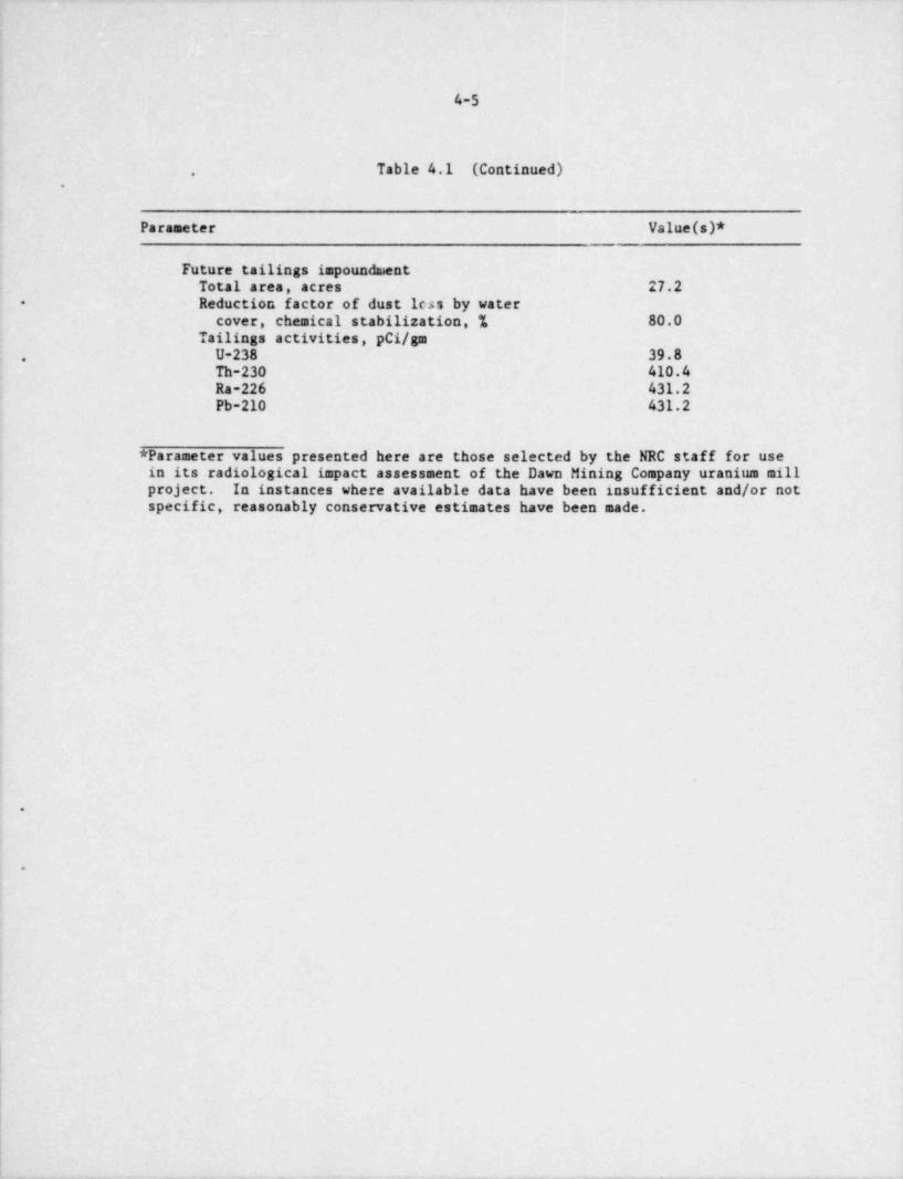
|
4-5
Table 4.1 (Continued).
.
Parameter Value(s)*
Future tailings impoundnaentTotal area, acres 27.2Reduction factor of dust leas by water+
cover, chemical stabilization, % 80.0Tailings activities, pCi/gm
U-238 39.8,
Th-230 410.4Ra-226 431.2Pb-210 431.2
* Parameter values presented here are those selected by the NRC staff for usein its radiological impact assessment of the Dawn Mining Company uranium millproject. In instances where available data have been insufficient and/or notspecific, reasonably conservative estimates have been made.
.
O
:
|
.
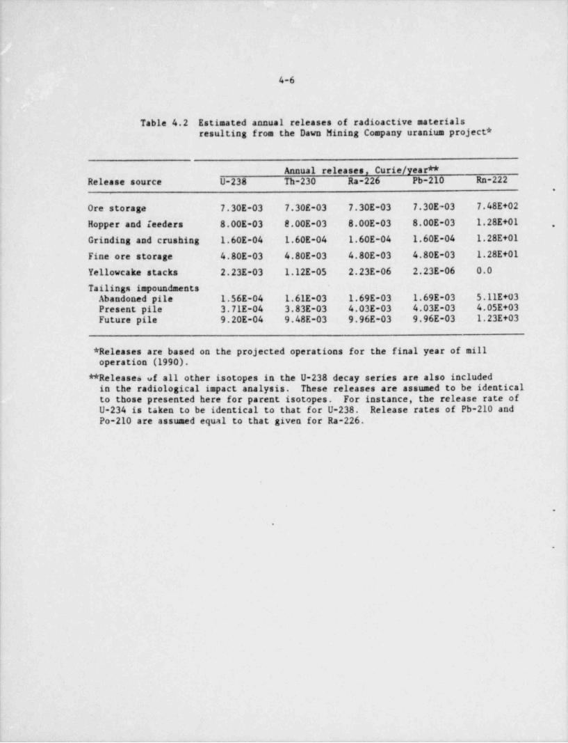
- -
4-6 l
|
Table 4.2 Estimated annual releases of radioactive materialsresulting from the Dawn Mining Company uranium project *
Annual releases, Curie / year **Release source U-238 Th-230 Ra-226 Pb-210 Rn-222
.
Ore storage 7.30E-03 7.30E-03 7.30E-03 7.30E-03 7.48E+02
Hopper and feeders 8.00E-03 8.00E-03 8.00E-03 8.00E-03 1.28E+01 ,
Grinding and crushing 1.60E-04 1.60E-04 1.60E-04 1.60E-04 1.28E+01
Fine ore storage 4.80E-03 4.80E-03 4.80E-03 4.80E-03 1.28E+01
Yellowcake stacks 2.23E-03 1.12E-05 2.23E-06 2.23E-06 0.0
Tailings impoundmentsAbandoned pile 1.56E-04 1.61E-03 1.69E-03 1.69E-03 5.11E+03Present pile 3.71E-04 3.83E-03 4.03E-03 4.03E-03 4.05E+03Future pile 9.20E-04 9.48E-03 9.96E-03 9.96E-03 1.23E+03
* Releases are based on the projected operations for the final year of milloperation (1990).
** Releases of all other isotopes in the U-238 decay series are also includedin the radiological impact analysis. These releases are assumed to be identicalto those presented here for parent isotopes. For instance, the release rate ofU-234 is taken to be identical to that for U-238. Release rates of Pb-210 andPo-210 are assumed equal to that given for Ra-226.
.
.
9
|
|

_ _ _ _ _ _ _ _ _ _ _ _ - - _ _ - . _ _ _ _ _ _ _ _ _ _ _ _ _ _ _
|. . . .
|
|
ORE FR0il tilNES
If
ORE PAD, FEEDAND GRINDING
a
%,4D
|1I 09
I k INHALATIONLEACHlNG AND y ? MANEXTRACTION RADON AND PARTICULATE 5
|. , . , , - . . . . ,. . . . . . . . , . . .
, ^ AIRS 0RNC DIRECT EXTERNAL _|
,, , . - "j ,, RAD.1,0AC{lVlTY;. - - EXPOSURE
^
gc, | ; ";:. '.- - z- a'
e gs - h s
TAILINGS d D h$TORAGE y |||
"5
g g RADIDACTIVITY;;; |N $0ll
U 2E
YELLOWCAKE DRYINGAND PACKAGING q
IRADIDACTIVITY INGESTION'
*
g
VEGETATION*
PRODUCT TOMARKET
TTL
Fig. 4.1 Sources of Radioactive Effluents from the Mill and Exposure Pathways to Man
-_ _ _ - - - - _ _ _ _ _ _ _ _ _ _ _ _ _

_ _ .__ - .
A
4-8
4.5 RADIATION DOSE COMMITNENTS TO POPULATIONS
The annual 100-year environmental dose commitments received by the (regional)population within 50 miles (80 km) of the site are presented in Table 4.4. Theprojected population distribution data (Table 4.5), based on the year 1990,were used to do the estimation.
'
Releases of radon gas yield radiological impacts which occur over a range ofthousands of miles from a release source. Impacts of radon releases from thefacility that occur within 50 miles (20 km) of the site have been included Jnthe tabulation of the regional population dose commitments (Table 4.4). Trans- -
continental radon-222 impacts have also been evaluated. Table 4.6 includestotal environmental dose commitments received by both regional and extra-regional populations. A grand total of 100-year environmental dose commit-ments received by all populations is also presented.
4.6 EVALUATION OF COMPLIANCE WITH REGULATORY LIMITS
Dose commitments to individuals at the locations noted in Section 4.4 werecalculated for the purpose of evaluating compliance with the limits specifiedby the U.S. Environmental Protection Agency's (EPA) 40 CFR Part 190, " RadiationProtection Standards for Normal Operations of the Uranium Fuel Cycle," whichwill be effective for uranium milling operations in December 1980. Under 40CFR Part 190, total doses to any organ of an offsite individual are limited to25 milliress/ year, excluding contributions from radon-222 and its radioactivedaughters. Table 4.7 provides a comparison of the calculated dose commitmentsto individuals with the 40 CFR Part 190 limits. Doses in this table are lowerthan the total doses (Table 4.3) because contributions from radon-222 and itsdaughters have been omitted.
As indicated in Table 4.7, maximum individual doses at the " nearest residence"and " nearest residence in the prevailing wind direction" locations are computedto exceed the EPA limits. However, by comparing doses from the present andexpanded (with the below-grade pit) operations it is evident that the contri-bution from the below-grade pit is quite small, with the major dose contribu-tion coming from present operations. Furthermore, as illustrated by Table4.2, the major source of radioactive particulates is the front end of the millcircuit. For example, at the residence (0.6 km NNE) with the highest doses, ~
the doses from the milling operation alone, excluding all tailings contributions,account for 97% of the total lung dose via the inhalation pathway, 93% of thebone dose via the inhalation pathway, and 68% of the hone dose via the vegetable .
pathway. From the analysis performed, therefore, it can be concluded thatconstruction and operation of the new impoundment will have little bearing onthe issue of overall site compliance with 40 CFR Part 190. However, furtherevaluation of the doses from the front end of the mill circuit and the needfor better effluent control must be considered immediately as part of thelicense renewal presently underway.
Under 10 CFR Part 20, air concentrations in unrestricted areas are limited tomaximum permissible concentrations (MCPCs). Table 4.8 presents the results of

:
)
.
49
-
E,,
e em nas as : s as ::= m ::s .:: 2:s -%I; sad ess A aes ses i i;s ass a as des i ses ess a J,
- s ~2:e x x = .- ~ ~
m.w* &
A => : ~,,.. . ~. ~ . , ~ ~ um..
-- ~...~. ~ . .,. ~. ~.n a ,.w . ~ . ~ . .:
- - -ses ses .: ;;s ess m se ess 4 se ese a ses ses ;-~. .c A
- - -= - e - - - .. ~.
. . g .
| 1 |.h I . s.e.m. . m.e.s. e.ss.s. :s.s. :. . s.s. .=.=.=. . .m. o.s.s. s::. . s.e.s. =. ,.g --. ... . -. .. .
. . .
... .. ... ~- ~... .. g g-. 3,. . ,- w .
K 3.J
g - h
e **s.*- .~- .~. .~, E . , ~. ~ s, -, ; .:~,. ,~.s ~.
~. ~. ~. .i . . . s. .:s : ~ ~ . ~ ~ . . .: ~ ,~ .~ :~. .--
.. ... ~ -3 m --. ... . . . ... ~ ~.. .. . . ~. ~.g- .,-,c sw 2
t. -
La s. ..
..~~~ ~. . s s ,,, s - ass .,,,s - . m ,,,,,~. . ~ . . ~ , , . , - s.w. , , . .. ~ ~ ~ . . -~~ ~ .- a was s;s ; xas sea a. ass ;;s g s;s eas a ses a;s s :. _g 3, 3, c - . - - - ~
I' - "r -
5 93: . 9 999. : i 13 -3~.99 *M.~ 4:9 993 : ' .9:~.. -.9 , :n.9. n.9:3 99 3-
3,, .- --u ~- . . . . - - -. .. 3~- g-- ~
3 =5- - -
:-.
~ _| =r 5b %- _
. ~ .g., ~.. . . . . ~ .~
- s. .. - - . .~gs. ... , ,.,. ~...- .. . ~ g ~. . g-.. . .. ~. . ~ . : r- *:
- 1- -
. -.~ . . t.-. .. n .. .. n - w
.. - - ..i...wy . . -
] "hE 2 *- .
O ". E .5 $E8. E $.$$. E.E.E. E $.E.3 U.E.S. 5 $.N.3. $E.E. .* E.E.$.*.E.E.9 I ,2.-. ... ~ - . - . . ~ ~ . . . - -.
7 g-g** - -
i e:-
2 1 *2 51 , , I 1
--- -
l'E 'E 8* '
-
.2. E2- . o - . o u- . . 6- .. a.g . .* 5** h 1% 8t. 8**g3 E*"e3 8** 2 E ** e2
: ;.g2.eg.3.. t. *E: *1 :; 2 so :--2 :;2 3 ;-[ 3 3.3- [ 2
3. *1- .e - 2. t g . .. g
2 . . : g--- e,2 =m; - t.:r = ; a
-- . y2:x : -etg= .
:: -:::g = ; .- -
,2. & 2m2-- fz 2- o fm 1-~ - -, -
-wi- .ww- -e- = e-= e- . .c--= -- .. -w.=- . -ww- - -ww- ~ -
't' .2- .w.w .
. .: }*. 2 It- * *
W. i 3*
8 ,w =|
.. - ..'." ~5 -
:I i
im i of -{g. a .,1 ., ,
5 -Iw
l .c_ i - 3 13 2 4 .'* *
.n,.w -. . -
T. E . . i,. s : S~ !."
-86 ""
.e *s W -. - -~ . ..
t:0 g3. .= m 3 u .- 5 ---3. ~3
* : : :' 2- -.. .
.n. . m- . . .o 6. .6
us uL, -i . 'n '' s 2 .*=. g g* ~#2g s .a u-
11
1\
|
II
|
lt
!
Il
_ _ _ _ _ _ _ . . _ _ _ _ _ _ _ _ _ _ _ _ _ _ _ __

** d'm eudi nl a 2ep 0 7 2 8 1 4 5h x 0 9 3 3 1 3 0 2, 1
tE 00i 6 0 5 5 0 0 8 1
p 4 5 4de 3 3 2 0 ,
t 4 el n 3 tae 2 n
s is 2 - eh e 9 8 7 5 3 4 3 U su s'r 1 . ecr 0 6 7 2 1 2 0 2,i
0 , s rd a nP0 8 r pa e o 7 0 4 4 0 0 7 1
3 er y r 0 1 4/B 3 3 2 0 2 t s
e s - h el e U g si r u om - d f a d- n e o d0 o d n .
5 s n s n ol r a e o i
nl e p t d tii p x 0 3 a a ahm E 7 0 7 2 8 1 8 0 l r i
4 9 3 3 1 3 6 2, 0 u dt ,
0 c f a .i m )i o rwu C 3 0 5 5 0 0 5 4
i D gt 1 5 0 tnn E nn r n doa ( ue a o nir Ls p i ut u s e t oa t r 0 2 f a rl y n P 3 9 8 7 5 3 8 0 o l g
1 0 a k2 6 7 2 2 4 2,un e s h c0pa m .
e n aop t 3 0 4 4 0 0 3 4pm i 1 5 0 s i b
o m alC m e e da o d l h nng C e e t aon d rii e n m0gn s a e o 9ei o p h r 7,rM D x t f
E 8 0 7 6 1 0 6 03 9 3 5 4 9 0 5 1 m g 3on l
6, 0 o n 4t w a0a t 6 0 5 1 3 3 2 r i
f t fsD n et 9 1 0t e nn 1 7 0 l one m oe g ueh n Bs n s emt o e i e zt r r 0 3 t r iif i P 2 9 8 1 5 5 1 l smo v 7 6 7 1 9 0 3 6, 0 u e
s s n0m non E 5 0 4 6 2 3 3 0 e o oco 7 9 7 0 r h i
i l t tet a e asa u . s e l
_ o r uor n .
d e n d h a pp A e t o
l o d m pa n e u
_ t e a 9 2 r i lnh yp 1 0 7 2 8 1 4 0 a l aet d x 2 9 3 3 1 3 3 6, 0 e n
0 e h om oE n t inm B 0 0 5 5 0 0 2 3oo 1 5 0 o i grr e b p e
e rif l ._ v ot d .ng h n n l een We 9 2 a a h
i s 8 9 8 7 5 3 4 0 i th1 6 7 2 2 3 8, 0l t e 1 ,
0 g c nal r .
uu P 0 0 4 4 0 0 0 3 n n ons 1 5 0 u . o .
ne l 0 r dAr ,1 b e
2 sy- e a .
e db h b t4s e oP t n
4 od s b e e .d n o d o r mt
e u ld en t a d nl d no a l l a neb n d n or una o s s .uma u u o i g nor h , e e2 od
T o o i tk niu w6 s s3 pny r l t ac att 2 o o mua g c s l a aa e2 d d eiow e n n ub ll n h - c ph m m g o o p au * t a n d nwmt o o n i i ol t pm* R o neeia r r i t t pa ooo* o i urn
P n f f s s l r t prd t , t oe w_ o e e e a d u f n 0 a rft e
e i l l l g g t et fl u s3 l geunr t a a b n n o t a oat o e2 a kRou a n n a i i T an nar s - h c hh
_ s l r r t m ooh g oh n ant t_ o a e e e t k i m iitk DT I Biii_
p h t t g a l t o t g c * * * WWx n x x e e i sr aeoa * *_ . .
_
E I E E V H M Ef Rrtb * . -
_
_
__
_
_

. -
-
b.
.-
.-
. e.
.
W5 e 5 5 5 e 1 o 1 1 1 1 1 . 1N l l 2 t 1 1 1 1 1 2N7 1
.
3 .3 .
.
.l
-
We 0 5 e e 1 7 9 1 1 1 l 60.
l l 1 l l 2 3 5 1 1 1 I 0i N5 1 3M 1
3yn . .
W5 5 5 5 e e 2 1 2 1 ! 1 1 . 4a .
p N l l 5 2 3 2 ! 1 1 9
m N2 1 .
9o 2Cg 0 e 0 6 1 1 2 3 7 7 6 2. 5n 0
l 1 1 2 4 5 5 2 2 021 7
. i W0 4 1 9n 7i 2M
.
n W5 0 5 5 5 6 2 2 1 3 2 9 9 . 9w S 1 5 5 2 5 a 5 7 2
. W7 3 1 8 9a 4 1 . 1D 2
e .
.h 0 5 5 5 5 6 1 1 3 9 2 2 3 7t W 1 2 2 5 9 1 5 5 4
eS5 6 2 5 6f 2 1 . 2o 2
e
s2u W5 5 0 0 o 2 2 2 9 9 3 2 6
$ 1 1 t 5 5 5 5 5 5 3 3 2 SiS2 1 1 6 Nd 0 Oa 2 SR R
'Ee 0 0 0 1 1 1 2 0 9 9 9 9 4 5 P1 1 2 2 2 5 4 5 5 5 5 8 9l
i S0 5 1 1 1 1 5 . s 0M 8 . i 9
- 1 . 70 . 05 . 3
E5 5 0, a 1 1 1 2 4 0 1 2 s 42- S 1 l 2 3 3 5 4 5 5 6 1 s- S7 0 0 5 2 2 . 2 Sn 5 4 0 7 0 Io 1 1 . 3i . Nt . Ou 0 5 0 6 1 1 2 0 3 5 7 2 8 0 I
5b E 1 1 2 3 5 1 9 5 0 6 2 Ti S5 2 1 6 4 0 6 3 Ar 3 5 7 0 1 5 L
1 1 8 1 1 Ut1 2 Ps
i OE5 6 o 6 1 2 2 9 8 4 0 6 9 3 PD S t 2 3 5 5 5 6 1 6 8 8 5E2 2 6 6 3 1 9 2 Mn 1 1 9 6 3 3 2 . 7o 1 3 9 . 4 ~ K
i . 1 0t . 8
3 5 5 5 2 5 0 2 9 9 6 0 1a 05 0 7 e 9 1 0 1 6 1l
u E0 1 9 s 2 3 1 2 52p 9 6 3 3 L
o 1 ATP . O %
E5 0 6 1 6 6 0 0 9 9 9 3 9 a T0 N 1 1 2 1 2 5 7 1 1 8 7 8 s9 E7 2 9 3 3 3 2 9 . 4. 9 6 2 1 61
d0 i 6 6 1 2 2 3 1 1 7 1 . 6e 01 l 1 1 3 5 5 5 1 1 7 1 . 5t E
c N5 3 . 6. 4 .e
jor E5 3 3 o 6 2 5 8 3 l 1 1 l 4
P N t 1 5 0 7 5 i 1 1 I 6N2 1 2 5
25
.
4 .3 5 5 5 2 2 5 3 2 6 6 6 00
5 5 0 S 4 0 0 3 7e NO 1 2 1 1 2 9l 2 5 7b .a .T .
.* ' . * ' * * ' **' * ' * ' , ' . . ' ,
.S
0 0 0 0 0 0 0 0 0 0 00. . 0R
ET 2 3 4 5 0 0 0 0 0 0 0 0 0
N . . . .1 2 3 4 5 6 7 8
s.E
.
- 0 0 0 0 0 0 0 0 0 0 00. 0O
L_ I 1 2 3 4 5 0 0 0 0 0 0 0 1_ K 1 2 3 4 5 6 ?_
_
__
_
__
__
___
!|| t|1|

.
.
6 em 0 ,hud - etie E lld . . . 9 poen 8 8 6 8 ot
eha 5 3 9t p 3 5 8 4 prix a .
pE ne .
s e 6 oy tn 0 i/ ne l t - l a ei an E l e mt ie . . . 4 i r dc hs 7 8 5 3 mi n .
ce 1 7 9 l ul ,
u r nr 3 4 7 4 4. l opl a oP i pol e r 6 m mpi y B 6 i
m / 30l s 6 0 wam e 0 f5 et u r d - o nni - e E den n d 2 nn hna o n 6 5 0 1 oa t
. i ii r s at u r p 5 5 1 1 t g Wn e x 1 2 4 an 4oy P E l u +cn g 5 ul
n 0 p .a ,
op ) ut - od tt m C Ln E pn n
o D e 4 3 7 4 a el msC E s 7a , dt ( e 3 2 5
ng r 1 2 3 9 t e nen s P nn umi t eo ot n n nb pii e 5 i mmM m d 0 t , im t e - nyon i d E od wcw m n . . 7 co e
a m a 2 4 5 b n.
0eD o p 1 6 5s C x 1 5 7 4 9 e toe E 1 6 9l udh e e 1 1 o o
t s n 5 h hl o ot 0 rw taf D B n - a i
W+t o e 3 E een l s . . 4 yhen a e 3 7 0 0 t
f .mo t r 9 8 8 'ni n P 3 4 4 ooot e 1 1 t -ra m s 0i r n i r 1
ve o y4 6 sanp r d + 0 ae xeo i od - by
v B e E / 69 ea 03l e n d .
4 h eah E en . .
ut l a 2 6 8 t r 3n l op 1 1 2 3 i
nm a h x 1 1 nl sAo t WE ol e
r o * i t
6. f T * d m o .
s 6 e n4 + n 0 t0 e
t o a0 de n l i E m1
l t 6 i 63l et g. i . a 0 0b s .
snm -a e 0 2 m 2 lT r 1 0 1 u 3 eiu E
P 1 e 1 p vi 60h o sil
y y t p eeeb b uch 3
f f l l etd no d no a ari neo eo t v p ovim vim n ne i
itk itk sye f* d o tb n od nsl aea ea '
cl0 cl0 C i n ura teu8l eu8 Ddt nu oei orp l rp E en oo r ph n
oni od vo ir g cs pi m spn li c t g kh n e
h o ae ck cco h'C e t e 'C e y t ce ac aar T- Dhih Dh e oeh ra B eb *- Et wt Etb Trt Fb * *__
!
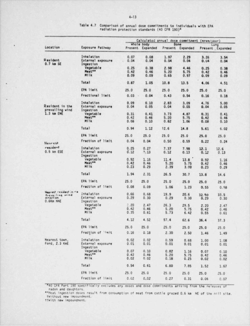
4 13
Table 4.7 Ccaparison of annual dose commitments to individuals with EPAradiation protection standards (40 CFR 190)*
.
Calculated annual dose commitment (mres/ year)Whole body Bone tung,
Location , Exposure Pathway Present Expanded Present Expanded Present . Expanded
Inhalation 0.07 0.08 1.97 2.29 3.26 3.54R esident External exposure 0.04 0.04 0.04 0.04 0.04 0.04.
0.7 km SE IngestionVegetable 0.25 0.38 2.98' 4.46 0.25 0.38Meat ** 0.42 0.46 5.20 5.75 0.42 0.46Milk 0.09 0.09 0.65 0.97 0.09 0.09
~
Total 0.87 1.05 10.8 13.5 4.06 4.51,
EPA limit 25.0 25.0 25.0 25.0 25.0 25.0Fractional limit 0.03 0.04 0.43 0.54 0.16 0.18-
- .
Inhalation 0.09 0.10 2.83 3.09 4.76 5.00Resident in the External exposure 0.04 0.05 0.04 0.05 0.04 0.05prevailing wind Ingestion1.3 km ENE vegetable 0.31 0.41 3.73 4.87 0.31 0.41
Meat ** 0.42 0.46 5.20 5.75 0.42 0.46Milk D.08 0.10 0.82 1.06 0.08 0.10
Total 0.94 1.12 12.6 14.8 5.61 6.02
EPA limit 25.0 25.0 25.0 25.0- 25.0 25.0Fraction of limit 0.04 0.04 0.50 .0.59 0.22 0.24
redent Inhalation 0.25 0.27 7.37 7.98 12.1 12.60.5 km ESE External exposure 6.12 0.13 0.12 0.13 0.12 0.13
Ingestion,
vegetable 0.92 1.16 11.4 13.8 0.92 1.16Meat ** 0.42 0.46 5.20 5.75 0.42 0.46Milk 0.23 0.29 2.39 3.00 0.23 0.29
Total 1.94 2.31 26.5 30.7 13.8 14.6
EPA limit 25.0 25.0 25.0 25.0 25.0 25.0Fraction of limit 0.08 0.09 1.06 1.23 0.55 0.58
|,! *f;Y' Inhalation 0.66 0.68 19.9 20.6 32.qo 33.5a .ote. External exposure 0.29 0.30 0.29 0.30 0.29 0.300.6Km NNE Ingestion
Vegetable 2.20 2.47 26.3 29.5 2.20 2.47Meat ** 0.42 0.46 5.20 5.75 0.42 0.46Milk 0.35 0.61 5.73 6.42 0.55 0.61
Total 4.12 4.52 57.4 62.6 36.4 37.3.
EPA limit 25.0 25.0 25.0 25.0 25.0 25.0Fraction of Wit 0.16 0.18 2.30 2.50 1.46 1.49
| Nearest town. Inhalation 9.02 0.02 0.59 0.68 1.00 1.08.
Ford, 2.3 KmE External exposure 0.01 0.01 0.01 0.01 0.01 0.01i
i Ingestionvegetable 0.07 0.10 0.82 1.16 0.07 0.10Heat ** 0.42 0.46 5.20 5.75 0.42 0.46Milk 0.02 0.02 0.18 0.25 0.02 0.02
Total 0.54 0.61 6.80 7.85 1.52 1.67
EPA limit 25.0 25.0 25.0 25.0 25.0 25.0| Fraction of limit 0.02 0.02 0.27 0.31 0.06 0.07l '
( "40 CFR Part 190 specifically escludes any doses and dose commitments arising from the releases of I
| radon and daughters,i
** Meat ingestion doses result from consumption of meat from cattle grazed 0.6 km NE of the ntil site. 1
TWithout new impoundment.itWith new impoundment. i
.

. _ _- - - ._ _-. . - - -- - - _ - . - ..-. . - . _ . . _ . .--
.
4-14
the staff's evaluation of compliance with 10 CFR Part 20 for calculated annualaverage air concentrations for selected restricted area boundary locations. Asindicated by the results presented in Table 4.8, there does not appear to beany problem in meeting the NPC limits specified in 10 CFR Part 20. In additionto the locations' evaluated in Table 4.8, other locations along the restrictedarea boundary were evaluated but were found to have lower computed average airconcentrations. In all cases, the incremental air concentration increases due ,
to releases from the new impoundment were inconsequential.
4.7 OCCUPATIONAL RADIATION EXPOSURE,
Uranium mills are designed, built, and operated to minimize exposure of boththe mill workers and the general public to radiation. Occupational exposuresfor workers are required to be monitored and kept below regulatory limits. Inaddition, protection measures to reduce occupational exposures are periodicallyreviewed and revised in accordance with the requirement to make such exposuresas low as is reasonable achievable.
The scope of this NRC staff review has not included a review of the inplantradiological safety program proposed for the mill. However, occupationalexposures can be characterized in general terms. Special studies at selectedmills have shown that the exposures of mill workers to airborne radioactivity,
+
are normally below 25 percent of the maximum permissible concentrations givenin Appendix B of 10 CFR Part 20 and that external exposures are normally lessthan 25 percent of 10 CFR Part 20 limits (Refs. 21 and 22). A recent review(Ref. 22) of mill exposure data by the NRC staff has indicated that only a fewuranium mill employees may have exceeded, over a one-year period, 15 to 20percent of the permissible exposure to ore dust, 25 percent of the permissibleexposure to yellowcake, or 10 percent of the permissible exposure to radonconcentrations. Except for a few individuals, the combined exposure of anaverage worker to these radioactive components over a one-year period probably
,
does not exceed 25 percent of the total permissible exposure.'
4.8 RADIOLOGICAL IMPACT ON BIOTA OTHER THAN MAN
Although no guidelines concerning acceptable limits of radiation exposure havebeen established for the protection of species other than man, it is generally ,
agreed that the limits for humans are also conservative for those species(Refs. 23-30). Doses from gaseous effluents to terrestrial biota (such asbirds and mammals) are quite similar to those calculated for man and arisefrom the same dispersion pathways and considerations. Because the effluents -
; of the mill will be monitored and maintained within safe radiological protectionlimits for man, no adverse radiological impact is expected for resident biota.
i
The staff considers that operation of the new impoundment will not significantlyincrease either the magnitude or variety of radiological impacts to biota'
resulting from operation of the Dawn facility as a whole.j
|:
|i
~
_- - _. . _ _ _ _ _ . . _ _ _ _ _ . - - . - - - . _ - - . - - - _ - _ - - . - _ - - - - - --

_-. _- -
. . * *
.
Table 4.8 Comparisons of air concentrations during mill generation with 10 CFR Part 20 limits for unrestricted areas
Total air concentrations, pC1/m , of radionuclides8
U-238 U-231 Th-230 Ra-226 Pb-210 W La Concentration10 CFR Part 20 limits ** 5.00FJ00 4.00E+00 8.00E-02 2.00E+00 4.00E+00 3.33E-02
'
Prridicted values: Present Expanded Present Expanded Preseht Expanded Present Expanded Present Expanded Present Expanded
R:stricted areaboundary (0.3 km NE) 3.43E-02*** 3.43E-02 3.43E-02 3.43E-02 3.42E-02 3.45E-02 3.42E-02 3.45E-02 3.42E-02 3.45E-02 1.55E-03 1.69E-03Fraction of limit ~ 6.86E-03 '6.86E-03 8.58E-03 8.58E-03 4.28E-01 4.32E-02 1.71E-02 1.73E-02 8.55E-03 8.62E-03 4.65E-02 5.08E-02Rrstricted areaboundary (0.1 km N) 2.34E-02 2.34E-02 2.34E-02 2.34E-02 2.36E-02 2.40E-02 2.36E-02 2.40E-02 2.36E-02 2.40E-02 1.7t.E-03 1.90E-03Fraction of limit 4.67E-03 4.67E-03 5.84E-03 5.84E-03 2.95E-01 3.00E-01 1.18E-02 1.20E-02 5.90E-03 6.00E-03 5.23E-02 5.69E-02Rastricted area s'
Lboundary (0.2 km W) 1.52E-02 1.52E-02 1.52E-02 1.52E-02 1.55E-02 1.60E-02 1.56E-02. 1.61E-02 1.55E-02 1.60E-02 2.35E-03 2.53E-03 *Fraction of limit 3.04E-03 3.04E-03 3.80E-03 3.80E-03 1.94Et01 2.00E-01 7.80E-03 8.03E-03 3.88E-03 4.01E-03 7.06E-02 7.61E-02
"WL denotes " working level." A one-WL concentration is defined to be anf combination of air concentrations of the short lived Rn-222 daughtersPo-218, Pb-214 Bi-214, and Po-214 that, in one liter of air, will yield a total of 1.3 x 10⁵ Mev of alpha particle energy in their completed: cay to Pb-210. Predicted values given for outdoor air are those calcuhted on the basis of actual ingrowth from released Rn-222.
'a* Values given are from 10 CFR Part 20, Appendix 8. Tabla II, Column 1.-
***The notation 3.43E-02 denotes 3.43 x 10 2,
.
e
b
.
.
e
.
.O
_ _ _ _ . _ _ _ - - - _ _ -
. _ _ _ _ _ _ _ _ _ _. . _ _ _ .. _ _ . - _ = _ _ _ . _ _ _ _ _ _ _ _ _ . _ _
i 4-16
4.9 SIRGIARY OF RADIOLOGICAL IMPALTS AND CONCLUSIONS-
; On the basis of this predictive analysis, which is based on reasonably conserv-ative assumptions, it appears questionable whether the Dawn facility canoperate in compliance with 40 CFR Part 190 without better control of milleffluents. As indicated in Table 4.7, maximum individual doses at the " nearestresidence" and " nearest residence in the prevailing wind direction" locations
i are computed to exceed the EPA limits.. However, by comparing doses from thepresent and expanded (with the below grade pit) operations, it is evident that
,
,the contribution from the below-grade pit is quite small, with the major dosecontribution coming from present operations. Furthermore,'as illustrated byi
Table 4.2, the major source of radioactive particulates is the front end of1
! the mill circuit. From the analysis performed, therefore, it can be concluded -
j that construction and operation of the new impoundment will have very littlebearing on the issue of overall site compliance with 40 CFR 190.
,
j Further evaluation of the doses from the front end of the mill circuit aad the; need for better effluent control must be considered immediately as part of the; license renewal review presently underway.
In addition, the dose estimates reported herein must be verified by empirical;j data obtained through detailed effluent and environmental monitoring programs ,
i such as are specified in USNRC Regulatory Guide 4.14, " Radiological Effluentand Environmental Monitoring at Uranium Mills" (issued as Revision 1, April25, 1980). Therefore, it is recommended that such a monitoring program beinstituted promptly, if not already in place. The monitoring program should becomprehensive in scope and should be capable of providing conclusive evaluationsof 40 CFR Part 190 compliance; a quality assurance program satisfying theguidelines of USNRC Regulatory Guide 4.15, " Quality Assurance for RadiologicalMonitoring Programs (Normal Operations) Effluent Streams and the Environment,"(issued as Revision 1, February 1979) should be implemented. Because 40 CFRPart 190 compliance is so obviously and strongly coupled with land use anddemography in the immediate site area, the mill operator should be required by
| license condition to conduct a semi-annual survey of land use (grazing, inhabitedstructures, wells, etc.) in the area within about 2.5 miles (4 km) of the
'
mill, and submit a written report to the state.
; Also, because compliance with 40 CFR Part 190 must be assured, and because allradioactive emmissions should be kept as low as practicable in any event, the
,i mill operator should be required by license condition to keep all effluent; control equipment in good working order and in use at all times during mill
operation.'
.
The staff's analysis of 40 CFR Part 190 ccepliance has assumed that the presentlyactive tailings impoundment will be decosusissioned and promptly treated so asto reach a high degree of control (97 percent) of potential particulate emissionsfrom that source. Therefore, the mill operator should be required by licensecondition to take appropriate actions to control particulate dusting frca thepresent impoundment by any available means to levels which are as low aspracticable. Exposed tailings beaches should be kept moist, treated with
'
!|
l
, , . _ . , _ _ _ _ _ _ . . _ _ _ - _ . , _ _ , _ - - , , . . , _ , _ _ - , _ . . . . . _ _ , _ . . . _ _ . . . _ , _ _ .

4-17
chemical stabilizers, or covered with wood chips at all times so as to preventthe unnecessary blowing of particulate tailings debris. Similar controlshould be exercised with respect to the abandoned tailings areas and the newimpoundment so as to keep releases of particulates from these sources as low
'as practicable..
.
I
I
L
G
e
|
s
|
__
, _ _ _ _
l
.
5-1
5. ENVIRONMENTAL EFFECTS OF ACCIDENTS
' The occurrence of accidents can be minimized through proper design, construc-tion, and operation as well as a quality assurance program designed to estab-lish and maintain safe operations. The applicant has submitted an environ-mental impact statement and plans for the design and construction of a below-grade pit. These submittals have been reviewed by the NRC staff to ensure
j that there is a basis for safe operation. Moreover, the state of Washington,
will maintain surveillance over the plant by conducting periodic inspections1
I of the facility and by requiring reports of effluent releases and deviationsi from normal operations.
,
Notwithstanding the above safeguards, accidents involving the release ofradioactive materials or harmful chemicals have occurred in uranium millingoperations. Therefore, in this assessment, accidents which might occur duringoperation of the proposed impoundment have been postulated and their potential
] environmental impacts evaluated.
Inadvertent release of the tailings solution to the environment could resultfrom an overflow, a rupture in the tailings distribution piping, or a failureof the pit side slopes resulting in liner damage and/or failure of the exist-ing impoundment (deep-seated failure of the north slope). Failure of the sideslopes could be attributed to a destructive earthquake or structural failure.Release of tailings due to a failure in the embankment around the pit will be lessentially precluded since the operating level of ponded tailings will be atthe natural ground level.
The below grade pit could overflow only if the pit was left unattended forseveral weeks. The required 5-foot (1.5-a) freeboard of the pit is more thanadequate to contain the design flood (see Section 3.2.1.6.2).
An analysis by the applicant's consultants concluded that the side slopeswould be stable under both static and earthquake conditions, meeting theminimum factors of safety prescribed in NRC Regulatory Guide 3.11 (Ref. 7).The NRC staff has concluded that the design meets the criteria prescribed inNRC R.G. 3.11. Even if a side slope failure occurred, however, the majorityof tailings released from the existing impoundment would probably flow intothe excavated pit. As the pit is filled with tailings from: normal operations,,
the weight of the tailings against the side slope should preclude any possiblityof a slope failure.
Based on the above discussions, the only probable failure that would result in |-
significant offsite releases would be a break in the tailings distribution |
piping resulting in a release of slurry.
It is not possible to predict the probability of a pipeline failure specificto the Dawn mill with a reasonable degree of accuracy. Even if the frequencyof such an event were known accurately, it would be difficult to predict themagnitude of the release of tailings slurry or solution. However, tailingse
releases have occurred in the past, and the data from these releases mayprovide a conservative indication of the expected consequences of dam and
i
|
||
- . . - --_ _ - - -

I
5-2
pipeline failure. A summary of incidents recorded for the period 1959-1979 ispresented in Table 5.1.
Based on these historical data, the average release from tailings das f 11ure9 ) of7
orfloodingfortenjncidentswas9pproximately1.4x10 gal (5.5 x 10 L
liquids and 3.0 x 10 lb (1.5 x 10 kg)5 f solids. Pigeline failures resultedin an av9 rage rel. ease gf about 9.2 x 10 gal (3.5 x 10 L) of liquids and .
1.8 x 10 lb (8.2 x 10 kg) of solids.
Six out of ten releases involving das failure or flooding reached the water-course, and five out of seven releases from pipeline failures reached the -
watercourse. However, most failures in the tailings distribution piping wouldresult in release of the slurry to the tailings pond and not to the environ-ment. Since many of these dikes and pipeline distribution systems were poorlyconstructed and current impoundments have more stringent design requirements,the probability and magnitude of past releases should overestimate any futureaccidental releases.
The average concentrations of radionuclides in the tailings solution, asmeasured by the applicant, are compared with applicable standards in Table 5.2.In addition, dissolved minerals from the ore are found in the solution.
f. Any large release of tailings slurry from that portion of the tailings pipe-line that is not within the tailings impoundment area, would likely reach theChamokane Creek to the north or west. In order to preclude the occurrence oflarge releases from the pipeline, Dawn will be required to install an audibler visible alarm in the mill control room or office which would activate.tomatically upon a pipeline failure. The monitor would be located at the
discharge point of the pipeline. '
Should any release of tailings occur, it is recommended that appropriateofficials of the state of Washington be informed immediately of the approxi-mate time of the accident and be provided with estimates of the quantities ofliquids and solids released.
.
.
~
__
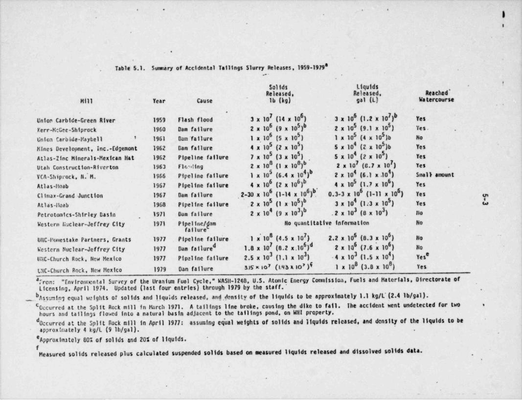
_ _ _ _ _ __ __ _ _ . _ -. . -
t
. . . .
|-.
-
.
.
..
Table' 5.1. Suuriry of Accidental Tallings Slurry Releases. 19'59-19798,
.
ISollds Liquids -
Released. Released. Reached *
Mill Year cause Ib(kg) gal (L) Watercourse'
. .
Union Carbide-Green Alver 1959 Flash flood 3 x 10I (14 x 10 ) 3 x 10 gj,g .x 10 )b y,, ,6 6 7
5 5Kerr-McGee-Shlprock 1960 Dam failure 2 x 10⁶ (9 x 10 )b 2 x 10⁵ (9.1 x 10 ) y,,,
,
5 5' 1961 Dan'fallure 1 x 10⁶ (5 x 10 ) 1 x 10⁵ (4 x 10 )b NoUnion Carbide-Maybe11
Mines Development. Inc.-Edgemont 1962 Dam failure 4x10.(2x10) 5 x 10⁴ (2 x 10 )b Yes5 0 5
5 5Atlas-Ifnc Minerais-Mexican Hat 1962 Pipeline failure 7 x 10⁵ (3 x 10 ) , 5 x 10⁴(2x10) y,,
0 IUtah Construction-Riverton 1963 F1 reeling 2 x 10⁸ (1 x 10 )b 2 x 10⁷ (8.7 x 10 ) Yes .
4 4VCA-5hiprock. H.'M. 1966 Pipellne failure 1 x 100(6.4x10)b 2 x 10⁴ (6.1 x.10 ) Small amount
,
Atlas-Itoab 1967 Pipeline failure 4 ~x 106 (2 x 10 )b 4 x 10⁵(1.7x10) y,,6 6
Climax-Grand Junction 1967 Dam failure ,2-30 x 106 (1-14 x 10 )b[ 0.3-3 x 10⁶ (1-11 x 10 ) y,,0 6
Atla's-Itoab 1968 Pipeline failure 2 x 10⁵ (1 x 10 )b 3 x 10⁴(1:3x10) y,, |,,5 5,
Petrotomics-Shirley Dasin 1971 Das failure 2 x 10* (9 x 10 )b . 2 x 10³ (8 x 10 ) Ho3 3, ,
Western Nuclear-Jeffrey City 1971 Pipeline / gam. No quantitative infor1 nation Hofailurej
UNC-l'unestake Partners. Grants 1977 Pipeline failu're 1 x' 108(4.5x10) 2.2 x.106 (8.3 x 10 ) y,- -7 6
i
Western Nuclear-Jeffrey City 1977 Das failure 1.8 x 10I (8.2 x.10 )d 2 x 10⁶(7.6'x10) y,d 6 6
UNC-Church Rock. New Mexico 1977 Pipallne failure 2.5 x 10³ (1.1 x 10 ) 4 x 10³ (1.5 x 10 ) Yes'3 4
(L'IS x 10' )I 1 x 10⁸(3.8x10) y,,8t;NC-Church Rock. New Mexico 1979 Dam failure SK x 807
'Frcm: "Environraental Survey of the Uranturn fuel Cycle." WA5|l-1240. U.S. Atomic Energy Convalssloa. Fuels and Materials. Of rectorate of '1Licensing. April 1974. Updated (last four entries) through 1979 by the staff.
DAssuning equal weights of solids and liqu|ds released, and density of the liquids to be approximately 1.1 kg/L'(2.4 lb/ gal)._.
,
0ccurred at the spilt Rock mill in Kirch 1971. A tallings line broke, causing the dlke to fall. The accident went undetected for twoC e'
hours and tallings floacd into a natural basin adjacent to the tallings pond, on WHI property.d0ccurred at the Spilt Rock mill in April 1977: assuming eg'ual weigh.ts of solids and liquids released, and density of the liquids to beapprox!mately 4 kg/L (9 lb/ gal).
.
'Approximately 00% of solids and 20% of liquids. -
fMeasured solids released plus calculated suspended solids based on measured ilquids released and dissolved solids data.' ,
.
.
- t
.
e . . .. .
_ _ _ _ _ __
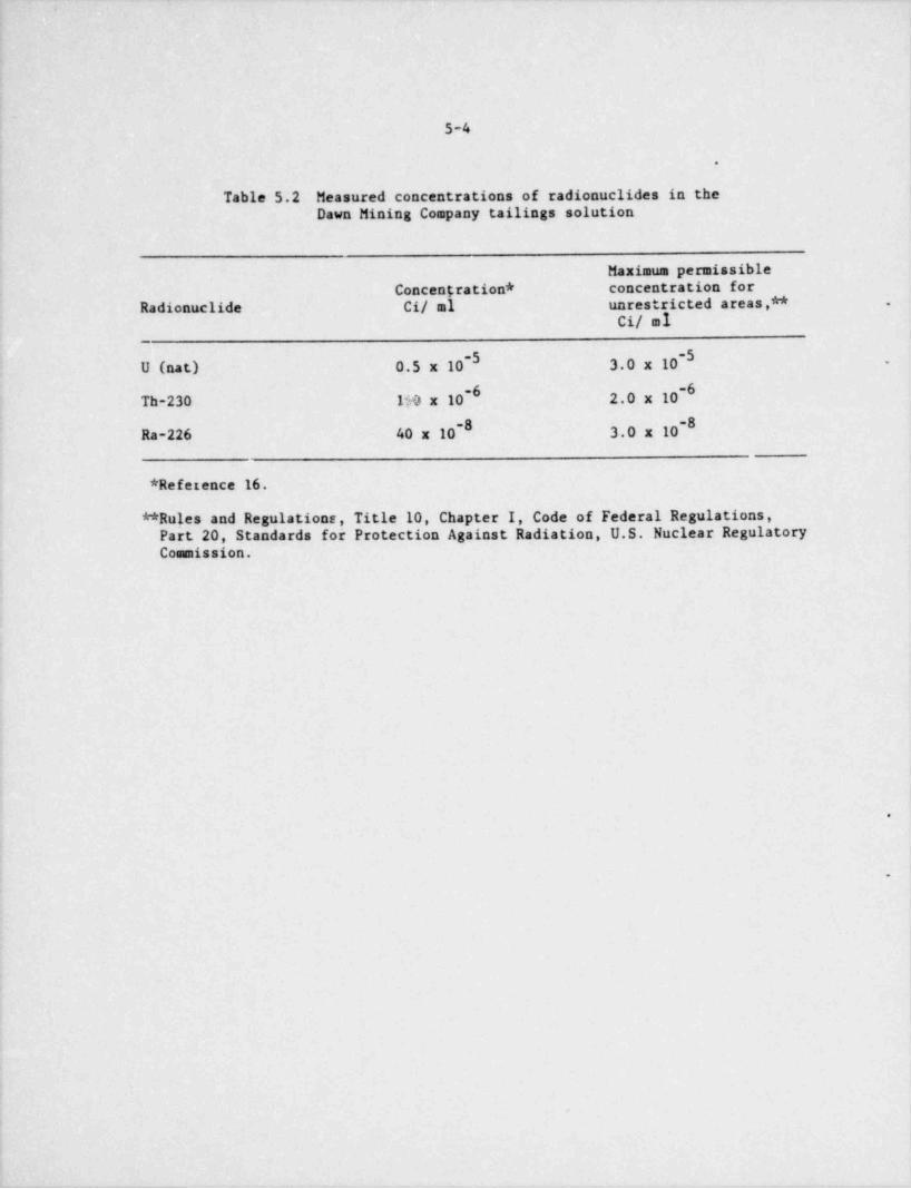
.
:
5-4
.
Table 5.2 Measured concentrations of radionuclides in theDawn Mining Company tailings solution
Maximum permissibleConcentration * concentration for
Radionuclide Ci/ al unrestricted areas,** .
Ci/ ml
-5 -5U (nat) 0.5 x 10 3.0 x 10 ,
~0 ~0Th-230 1$0 x 10 2.0 x 10
-8 -8Ra-226 40 x 10 3.0 x 10
* Reference 16.
** Rules and Regulatione, Title 10, Chapter I, Code of Federal Regulations,Part 20, Standards for Protection Against Radiation, U.S. Nuclear RegulatoryCommission.
.
e
!
!.
ad
_ _ ___ _ _ __ _ _ ____

_. ._
|
l,
|6-1
6.0 TAILINGS MANAGEMENT ALTERNATIVES
6.1 INTRODUCTION
Engineering techniques for controlling pollutants from tailings storage, bothduring operational and postoperational stages of a milling project, have been I
demonstrated. The unique characteristics of each mill facility must be identi- |fled and the appropriate environmental controls must be applied. i.
A set of tailings management performance objectives has been developed by theNRC staff against which each alternative is judged to ensure that potential
,
public health hazards that otherwise could occur are avoided or minimized.The performance objectives are as follows:
Siting and Desian
1. Locate the tailings isolation area remote from people such that popula-tion exposures would be reduced to the maximum extent reasonably achievable.
2. Locate the tailings isolation area such that disruption and dispersion bynatural forces is eliminated or reduced to the maximum extent reasonablyachievable.
3. Design the isolation area such that seepage of toxic materials into thegroundwater system would be eliminated or reduced to the maximum extentreasonably achievable.
Operations
4. Eliminate the blowing of tailings to unrestricted areas during normaloperating conditions.
Post-reclamation
5. Reduce direct gamma radiation from the impoundment area to essentiallybackground.
6. Reduce the radon emanation rate from the impoundment area to about twice.
the emanation rate in the surrounding environs.
i 7. Eliminate the need for an ongoing monitoring and maintenance program'
followiug successful reclamation.
I8. Provide surety arrangements so that sufficient funds are available tocomplete the full reclamation plan.
In the case of the Dawn Mining Company mill, the number of alternatives in| engineering techniques is constrained by the fact that the mill has been
operating for about 20 years and by the fact that accumulated tailings havealready affected the environment.
|
|
!
I .

i|
l.
|.
6-2
6.2 ALTERNATIVES,
6.2.1 Alternative Sites (Reference 58)
The use of alternative sites for tailings disposal is constrained by the factthat the current facilities have existed in their present locations for morethan 20 years. During this time, considerable amounts of tailings have accumu- .
lated at the mill site. Abandonment of the present site in favor of any ofthe other alternative sites considered here (except alternative No. I use ofSherwood mill) would inherently result in environmental impacts and contamina-
*
tion of yet another area remote from the current mills.
Alternative No. 1 Sherwood Mill
The possibility of using Western Nuclear's Sherwood Mill was examined. Twopossibilities exist:
_
(1) Use Sherwood mill to process future Dawn ores.(2) Continue milling at the Dawn mill and transport tailings to
the Sherwood mill tailing facility.
The Western Nuclear facility is fully committed to process ores from their ownmine and therefore does not have the capacity to process ores from Dawn'sMidnite mine. Even if the mill had sufficient capacity, toll milling chargesto Dawn would result in greater costs. In addition, the socioeconomic impactson the Spokane Tribe would be severe with increased unemployment, reducedpayroll payments and royalty payments. The distance from the Midnite mine tothe Sherwood mill is approximately the same as to the Dawn mill so no reducedtrucking costs would be attaiced.
Disposal of tailings from Dawn's mill at the Sherwood site would not eliminatethe environmental costs that would accrue from continued tailings disposal.Increased tailings deposition at the Sherwood mill will intensify operationalimpacts on the local environment. Additionally, the existing tailings pond atSherwood would have to be expanded thereby contributing to increased environ-mental costs. Furthermore, the Sherwood tailings area is not a below gradetailings disposal system in contrast to the Dawn proposal. It is estimated .
that trucking tailings to the Sherwood mill would cost in 1980 dollars $3.00per ton, a large increase in operating costs.
Alternative No. 2 Midnite Mine~
Disposal of tailings in existing pits at the Midnite mine was considered. Many |of the comments in alternative No. I would also apply here. The cost of thisalternative would be high; both monetarily and environmentally. The proximityof groundwaters to the surface at the mine site would be a major problem. Inaddition, the Company has practiced backfilling of completed pits. Consequentlythe two existing pits are still under development and could not be used fortailings disposal until they are completely mined out (current plans call forcompletion in 1982-3). Thus a tailings disposal area at the mill would still I
be necessary.
!|
|
l
|

I1
6-3
Alternative No. 3 North of Mill -
,
The area north of the existing mill was considered as a possible tailingsdisposal site. The geology and soils in this area are similar to those at theexisting site and would thus pose no advantage. In fact, the surface topographyposes a distinct disadvantage. Any site to the north would be in the ChaeokaneCreek flood basin. The existing site is over 100 feet above the creek elevation.
.
Alternative No. 4 South of Mill
The area south of the mill was examined as a possible disposal site. The area*
immediately south of the mill site is very similar to the project site exceptthat the valley fill material is less extensive i.e., bedrock is shallower.South of the Spokane River the Columbia River basalt outcrops with only a verythin layer of soil on top. Any excavations in these types of terrain wouldinvolve hardrock excavation with attendant high costs for no apparent benefitover the present location.
Alternative No. 5 East of Mill
To the east of the existing mill is a mountainous region extending into theDeer Park area. Deer Park is flat and its soils are mostly clays. The problemand cost of transporting the tailings 30 to 40 miles away overrides any advantageof the clayey soils.
Alternative No. 6 West of Mill
The area to the west of the mill, with similar geology and soils, was consideredas a possible alternative site. Its similarity to the existing site presentsno advantages that can be readily seen. In fact, tailings disposal in thisarea would require pumping tailings slurry across Chamokane Creek. Any breaksin the transfer pipe would pose an immediate threat to the creek and downstreamwater uses.
6.2.1.1 Evaluation of Alternative Tailings Disposal Sites
Since the present disposal site is already contaiminated it makes beiter senseto confine future disposal to the same site than to contaminate any other area,
without strong cause. This approach will retain the benefits in terms of thecost of perpetual monitoring and maintenance as well as frequent surveillanceduring the operatonal phase of the plant. Comparing the various alternatives 1
discussed, the DSHS feels that the tailings site area chosen is the most-
environmentally suitable. |
I16.2.1.2 NRC Siting Positico
The NRC staff does not require detailed evaluation of alternative sites forfuture tailings disposal at an existing mill provided that the onsite locationproposed by a licensee adequately satisfies the staff's performance objectives.The use of an alternative site would not greatly reduce the environmental
! impacts at the present site and in addition would create more environmentalI
|i I
|:
_
'
I
t
6-4
impacts at a new site. In addition, locating a new tailings impoundment atthe existing mill site avoids the proliferation of tailings disposal areas. l
6.2.2 Desian j,
The onsite alternatives for expansion of the tailings disposal facilities that '
have been evaluated by the applicant include the following: |.
1
I. Vertical additions to present impoundment dikes.I
II. Construction of a new dike impoundment adjacent to existing facilities. I*
,
III. Excavation of a subgrade storage pit.
The above tailings management alternatives were evaluated by the NRC staff I
with respect to the performance objectives listed in Section 6.1 as well aswith respect to their relative economic and environmental costs and relativelevels of resource utilization.
Alternative I represents the technology that has been in general use in the.
uranium milling itdustry in the past. The technology is now being phased outfor the reasons listed in the following paragraph.
The option of continued use of the impoundment was rejected for the followingreasons: (1) there is uncontrolled seepage contamination migrating from theexisting impoundment (2) above-grade disposal to even higher elevations wouldbe more susceptible to blowing of particulates during operation; (3) continueddisposal in the existing impoundment would result in additional seepage contam-ination and result in a higher above-grade mound after reclamation, therebyincreasing its susceptibility to natural erosive effects over the long term.Therefore, this alternative would not satisfy the staff's performance objectives 3,4, and 7.
Although Alternative I is initially the least expensive of the alternatives,it is probable that long-term maintenance and protection would make it the
'
most expensive..
Alternative I meets very few of the staff's performance objectives and forthese reasons must, therefore, be rejected regardlest of cost.
Alternative II would require a new aboveground area and construction similar -
to that of Alternative I except that greater protection against ground andsurface water seepage would likely be employed in a new design. This alter-
I native would be much more susceptible to long-term erosion and dispersion ofdry tailings during operation than pit disposal. Thus, this alternative does,
'
not satisfy performance objectives 2, 4, and 7 as well as Alternative IIIwould.
Alternative III represents a more modern view on the technology of tailingsdisposal. The tailings are placed in a pit well below grade and safety is
( assured for any ordinary climatic or geological event. Seepage to surface!
I
. -

6-5
waters is eliminated, and if, as in this case, an impermeable liner is used,penetration of pollutants to groundwater are also severely restricted. Dustingis minimized by the wind-sheltered locations of the tailings, well belowground level. On reclamation, the tailings can be covered with a thick earthand clay cover, and the final contours can blend into the natural surfacecontours, minimizing erosion. Thus, long-term stability would be more readilyachieved, and ongoing monitoring and maintenance would be unnecessary. Inaddition, the material excavated from the pit can be used in reclamation of,
the proposed and existing tailings areas. This would eliminate the need tostrip mine the materials from another source.
The prime option for the proposed tailings disposal facility as viewed by the*
NRC staff is p.'acement below-grade in a specially excavated, lined pit. Siteconditions for which below grade disposal might not be the most environmentallysound approach, such as a high quality groundwater formation near the surfaceor sound bedrock near the surface, are not present at the Dawn site. Therefore,the NRC staff agrees with the applicant's rejection of the above-grade alternativesand their decision to excavate a fully lined, below-grade pit.
6.2.3 Alternative Energy Sources (Reference 59)
6.2.3.1 Fossil and nuclear fuels
Introduction
The use of uranium to fuel reactors for generating electric power is relativelynew historically. Coal was the first fuel used in quantity for electricalpower generation. Cod se was reduced because of the ready availability andlow price of oil and x tal gas, which are cleaner burning than coal andeasier to use. Urani el is even cleaner (chemically) than oil or gas andat present is less exp , on a thermal basis, than any other fuel used togenerate electric power. following discussion concerns the relative
'
availability of fuels for ,wer generation over the next 10 to 15 years andcomparison of the health ef fects of utilizing coal and/or nuclear fuels asenergy sources.
Overview of U.S. energy usage and availability
~
Accore'.ng to the National Energy Plan, published by the Carter Administrationin A :il 1977, the United States uses more energy to produce goods and services1
than any other nation and consumes twice as much energy per capita as doesWest Germany, which has a similar standard of living.-,
In j975, the United States consumed approximately 71 quadrillion Btus (71 xy ), or 71 quads (q), of energy, with about 93 percent of this energy being10
supplied by three fossil fuels: oil, natural gas, and coal. Approximately 75percent of our energy needs are supplied by natural gas and oil; howeverbecause domestic supplies of these valuable resources are limited (about 7
i percent of proved reserves are oil and gas), the amount of oil imported fromforeign sources has increased, undermining our military and economic security.
. Table 6.1 illustrates the disparity between availability and usage of energysources in the United States.
l,.

_ _
,
l
|
|,
6-6
Table 6.1 Reserves and current consumption of energy sources
Percentage of proven U.S. energy Percentage of total U.S. energyreserves economically recoverable consumption contributed bywith existina (1975) technology each energy resource
Coal 90 ~18 .
Oil 3 46Gas 4 28Nuclear 3 3
,
Other 0 5
:
Source: Tetra Tech, Inc., Energy Fact Book 1977, prepared under thedirection of the Director, Navy Energy and National ResourcesResearch and Development Office, April 1977.
Despite concentrated efforts to slow down our consumption of oil and naturalgas, increase the usage of coalburning facilities, and further utilization ofnonconventional energy sources, energy demand forecasts indicate that by theyear 2000, approximacely 43 percent of our energy will still be supplied byoil and gas, 21 percent by coal, and only a small percentage (7%) by solar,geothermal, and oil shale (Table 6.2).
Table 6.2 Forecast of gross energy consumption for 1980, 1985, and 2000.
1980 1985 2000Percentage Percentage Percentage
12 12 1210 Btu of gross 10 Btu of gross 10 Btu of gross
Coal 17,150 19.7 21,250 20.6 34,750 21.3Petroleum 41,040 47.1 45,630 44.1 51,200 31.3Natural gas 20,600 23.6 20,100 19.4 19,600 12.0Oil shale 879 0.8 5,730 3.5 .
Nuclear power 4,550 5.2 11,840 11.4 46,080 28.2Hydropower & 3,800 4.4 3,850 3.7 6,070 3.7
geothermal.
Totals 87,140 100.0 103,540 100.0 163,430 100.0i
Of the 71 q of energy consumed in the United States in 1975, 20 g consistedof electric energy. An estimated 8.6 percent of this electric energy wasgenerated using nuclear fuels, but within ten years this percentage isexpected to increase to 26 percent. Coal was used for producing 59 percentof the electric energy generated by combustion of fossil fuels in 1975; oil andgas produced 20 and 21 percent respectively. Use of oil and gas to generate
' electric power has decreased about 10 percent over the last three years, a[ reflection of high oil prices and gas unavailability.
||
|.
. . . . _ _

.
6-7
Current and projected requirements for electric energy (1970-1985) and relativechanges in resources used for generation, as estimated in the ProjectIndependence report, are shown in Table 6.3. The evidence available at thistime indicates that, of the resources currently used in electric powergeneration (coal, uranium, oil, gas, and hydro), coal and uranium must be usedto generate an increasing share of U.S. energy needs. The supplies of oil andgas available for electric power generation are decreasing, and the UnitedStates does not have sufficient oil and gas reserves to ensure a long-run
~ supply.
Table 6.3 Estimated relative changes in resources to be usedfor generation of projected electric energy requirements-
Thermal energy required by years, %#Fuel resource used 1970' 1974 1980 1985
cCoal 45 45 45 46011 and Gas 38 34 25 16
dNuclear 2 4 17 26Hydro, waste, etc. 15 17 13 12
Total quads of energyrequired 15.6 20 25.5 34
* ActualEstimated from Federal Energy Administration, National Energy Outlook,U.S. Government Printing Office, Washington D.C., February 1976
cCoal usage must increase 77% by 1985 to attain this level.dUranium-fueled reactors furnished 9.9 percent of the total U.S. productionin January 1976.
Source: Federal Energy Administration, Project Independence, U.S. GovernmentPrinting Office, Washington, D.C., November 1974.
With increasing energy demands, both foreign and domestic, expectations are~
that in the next few decades the prices of oil and gas will increase rapidly asreserves of these two resources become severely depleted. Because of the timelag between initial extraction and consumption of the resource for energy.
production (three to five years from mine to generation plant for uranium andcoal, five to seven years for construction of a coal generating plant, andseven to ten years for construction of a nuclear generating plant), the exploitationof both coal and uranium resources mut be integrated with contemporary energyneeds. Although coal and uranium resources are adequate for foreseeableenergy needs, major expansion of both uranium- and coal-producing industries willbe required, as neither of these industries is considered capable of singlysupplying future energy requirements.
_

- . . . - . . . .- - - --- _ _ _ .
.
6-8
.
The determination of availability of uranium in large enough quantities tofuel the projected nuclear generating capacity (for 1985 and beyond) is currentlya matter of study.
Coal Production
Congress and the Carter administration have stressed, via passed and proposed .
legislation, the necessity of future decreases in oil and gas demand to alleviateour dependence on foreign energy sources and to re-orient our energy consumptionpatterns. The Project Independence report of November 1974 and the National
,
Energy Outlook of February 1976 both proposed that coal production be increasedfrom present levels (approximately 650 million tons per year) to approximately1.2 billion tons by 1985. The major expansion of coal production will likelybe in the west (from approximately 92 million tons in 1974 to about 380 milliontons in 1985), because of the low sulfur (low air pollutant) content of mostwestern coals. The potential for environmental damage (due to disturbance ofgenerally fr' agile ecosystems) in the western United States will be increased.Because the major markets for the coal produced will be located hundreds ofmiles from the western mines, transportation costs will be high, as will theenvironmental impacts associated with transportation systems. Currently,transportation costs for bringing western coal to the eastern United Statesaccount for the major portion of the market price. Also, for a given thermal
,
content, transport facilities for U 0 Per year are minimal compared to those,
33for coal because of the much higher ehergy content of uranium fuel. Approximately250 tons of U,0 per year are required for a 100-MW nuclear plant operating atg
coal plant would be more than 3 x 10{g coal requirements for an equivalent 1000-MWa plant factof of 0.8. Annual weste'
tons, or the load capacity of at least oneunit-train (100 cars of 100 tons each), per day of plant operation.
f
! Uranium fuel production
Estimates presented in the National Energy Outlook indicate that 140,000 to150,000 MWe of nuclear generating capacity will be needed to supply 26 percentof the total electrical energy used in 1985. The first Project Independencereport indicated that' nuclear capacity could increase to more than 200,000 MWe
.
by 1985. A more recent and lower estimate resulted from lower projections of; electricity demand, financial problems experienced by utilities, uncertainty . ,
t about government policy, . and continued siting and licensing problems. The imore recent projections or uranium requirements are given in Table 6.4.;
| -Table 6.4 Uranium requirements
,
j MWe operating Lifetime U 0 requirements (tons)3gby 1985 for specifica plant factori
0.8 0.6142,000 960,000 704,000
Source: Federal Energy Administration, National EnergyOutlook, U.S. Government Printing Office, Washington, D.C.
,
| February 1976.l'ii
!
! -- - . , . - n. , -- ,,
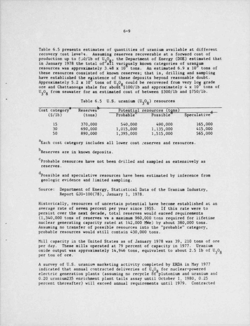
!
l,
6-91!
I
Table 6.5 presents estimates of quantities of uranium available at differentrecovery cost levels. Assuming reserves recoverable at a forward cost ofproduction up to $30/lb of U 0 , the Department of Energy (DOE) estimated thatinJanuary1978thetotalofaklvariguslyknowncategoriesofurangum3
resources was approximately 3.48 x 10 tons. An estimated 6.9 x 10 tons ofthese resources consisted of known reserves; that is, drilling and sampling
have established the egistence of these deposits beyond reasonable doubt.Approximately 5.2 x 10 tons of U 0 could be recovered from very lo]f grade. 38ore and Chattanooga shale for aboat $100/lb and approximately 4 x 10 tons ofU0 from seawater for an estimated cost of between $300/lb and $750/lb.38
Table 6.5 U.S. uranium (U 0 ) resources3g
Cost category" Reserves Potential resources (tens) ,
($/lb) (tons) Probable' Possible" Speculative"
15 370,000 540,000 490,000 165,00030 690,000 1,015,000 1,135,000 415,00050 890,000 1,395,000 1,515,000 565,000
*Each cost category includes all lower cost reserves and resources.bReserves are in known deposits.CProbable resources have not been drilled and sampled as extensively asreserves.
dPossible and speculative resources have been estimated by inference fromgeologic evidence and limited sampling.
Source: Department of Energy, Statistical Data of the Uranium Industry,Report GJ0-100(78), January 1, 1978.
Historically, resources of uncertain potential have become established at anaverage rate of seven percent per year since 1955. If this rate were topersist over the next decade, total reserves would exceed requirements(1,340,000 tons of reserves vs a maximum 960,000 tons required for lifetimenuclear generating capacity rated at 142,000 MWe) by about 380,000 tons..
Assuming no transfer of possible resources into the " probable" category,probable resources would still contain 430,000 tons.
(* Mill capacity in the United States as of January 1978 was 39, 210 tons of ore| per day. These mills operated at 79 percent of capacity in 1977. Uranium
oxide output was approximately 14,946 tons, equivalent to about 2.5 lb of U 038per ton of ore.
A survey of U.S. uranium marketing activity completed by ERDA in May 1977indicated that annual contracted deliveries of U 0 f r nuclear-powered38electric generation plants (assuming no recycle cf plutonium and uranium and0.20 uranium 235 enrichment plant tails assay until October 1, 1980, 0.25percent thereafter) will exceed annual requirements until 1979. Contracted
|
. _ _ _ _ _ . _ - _ - - _ _ _ _ _ _ _ _ _
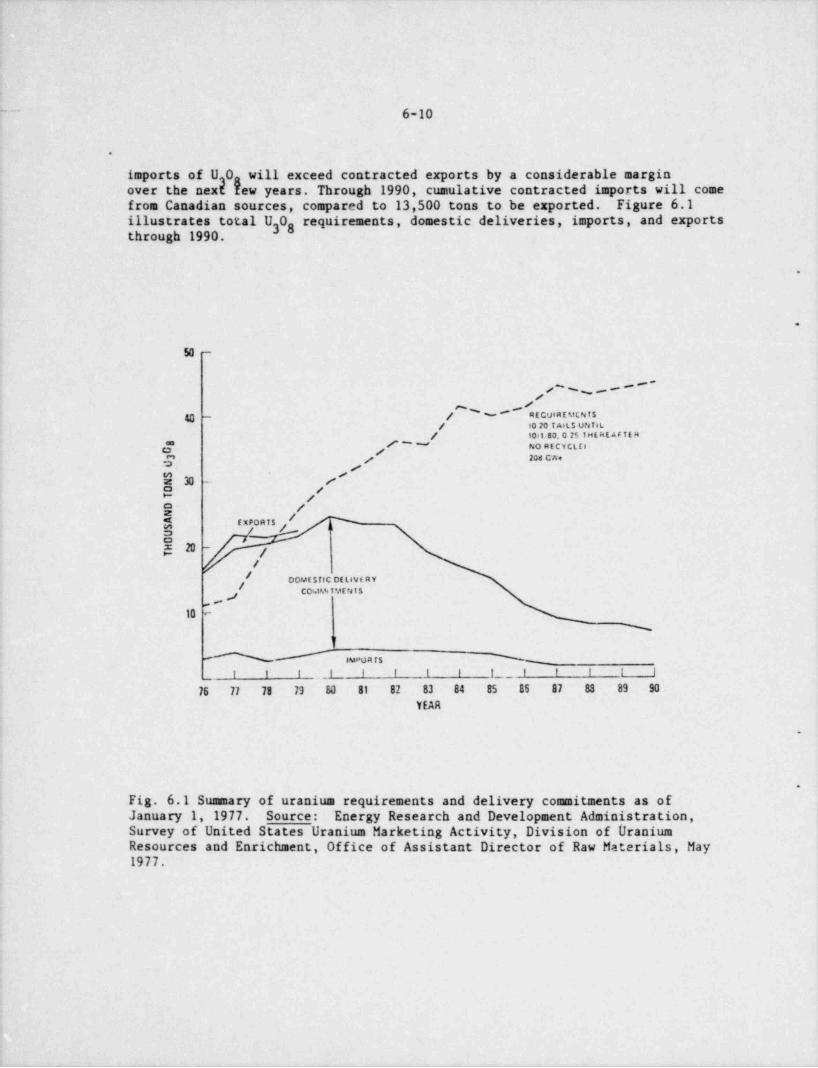
~~ 6-10
.
imports of U 0, will exceed contracted exports by a considerable margin3over the next Yew years. Through 1990, cumulative contracted imports will comefrom Canadian sources, compared to 13,500 tons to be exported. Figure 6.1illustrates total U 0 requirements, domestic deliveries, imports, and exports38through 1990
.
.
50 -
/'% p****
40 - / w# recut RE MCN T S/ 10 20 TMLS UNiaL
/ 10<1.83. 0 251HE f4E AF TE 84#'" NORfCYCLilO ' j
/ 204 CWeg
$3 ._. [? ,/E /
/ y5 ExPORis j5h ~
//
OOMisf tC OELIVE RYjCOkt%TME415j
to -
%
'I
h# woar$ %
i l I .I I I I I f_ l f I I i
76 77 78 73 50 81 82 83 84 85 BS 87 83 89 90
YEAR
.
.
Fig. 6.1 Summary of uranium requirements and delivery commitments as of .
|January 1, 1977. Source: Energy Research and Development Administration,Survey of United States Uranium Marketing Activity, Division of UraniumResources and Enrichment, Office of Assistant Director of Raw Materials, May1977.
|

6-11.
.
Cumulative U.S. supplies of U 03 8 (including domestic and foreign inventoriesand contract commitments) will exceed DOE enrichment feed requirements until1983. The gap between cumulative supply and cumulative requirements is expectedto be approximately 58,000 tons by 1985 and widen to approximately 233,000 tonsby 1990. (See Fig. 6.2)
-1
.
154632S00 -
f
/4% ~
/
//
#400 -p
// R(OUtF C U(NT S
# 10 701 AIL S UNTILf350 -p 10 t 80. 0 ?$ t ht k r a t if R.
/ NO RECDCitl 20t CWej
ynn - ,/s - -
-9 ,'.
G 250-
/
/o / CuvutAlivt 00VESTsc & Font sCNdM ~* #
f UR ANiuM Of t h tRY COMVetMf NTSPLU$ SUvf R$ INVif,10 RIES
150 - , /p
//E ' 8UYt R$' #
fINvf h10RitS #
#ON lit 77 p ,
#to -
,f 1977 DE LIVERY,m e COvuttwf Nisp
#l l f I i 1 9 1 f I f f I I1977 1978 1979 1980 1981 10A2 1983 1984 1985 **86 1967 1958 1989 '990
.
Fig. 6.2 Comparison of U 0 requirements and contracted deliveries plus38inventories.,
'Source: Energy Research and Development Administration, Survey of United ;
States Uranium Marketing Activity, Division of Uranium Resources I
and Enrichment, Office of Assistant Director of Raw Materials, May1977.
-
||
i
6-12.
Comparison of health effects of the uranium fuel cycle and the coal fuel cycle
Research conducted by the U.S. Nuclear Regulatory Commission comparing thehealth effects associated with the coal fuel cycle (mining, processing, fueltransportation, power generation, and waste disposal) and the uranium fuelcycle (mining, milling, uranium enrichment, fuel preparation, fuel transportation,power generation, irradiated fuel transportation and waste disposal) indicatedthat increases in the use of coal for power generation may cause the adverse .
health impacts related to electric energy production to increase'. As defined bythe study, health effects are stated in terms of " excess" mortality, morbidity,(disease and illness), and injury among occupational workers and the general
,
public, where " excess" implies illness and injury rates higher than normaland premature deaths. The estimated excess deaths per 0.8 gigawatt-yearelectric [GWyr(e)] (i.e. , per 1000 MWe power plant operating at 80 percent ofcapacity for one year) were 0.47 for an all nuclear economy (assumes that allof the electricity used within the nuclear fuel cycle is generated by nuclearpower) and 1.1 to 5.4 if all the electricity used in the uranium fuel cycle(primarily for uranium enrichment and reactor operation) came from coal-firedplants. Excess deaths for the entire coal cycle varied from 15 to 120 per0.8 GWyr(e). Mortality estimates are shown in Table 6.6.
Excess morbidity and injury rates for workers and the general public resultingfrom normal operations and accidents in an all-nuclear cycle were estimatedto be about 14 per 0.8 GWyr(e), with injuries to miners from accidents (falls,cave-ins, and explosions) accounting for ten of these occurences. If all theelectrical power used in the uranium fuel cycle originated from coal firedplants, these rates would increase to approximately 16-24 per 0.8 GWyr(e).The estimated excess disease and injury rate for the coal cycle was 57-210 per0.8 GWyr(e). Coal-related illnesses among coal miners and the general publicand injuries to miners account for the majority of nonfatal cases. Table 6.7illustrates these comparative illness and injury rates.
hh e, (,.$, Current eerft :w.ece e sc u too.t ehti sw. unary p i y. .* pee O R CWyr(c) pr,r. .e pl r.te
. . '. . . .. __..[ . TotafiAccutres Orsrw Arx.rl. n t Dw ;.4
PJue.l. .r fuel cycle
A.? a lar 0 72' 0 14* 0 0'/ 0 4. * 0.47 .
v..tutL .af.N rh.er.dteuwd ntM 0.24 - 0 W ' O 14 0 4f ' O.1(f f 0El 4 G* 1.1-54ts.4 cy .: v&d tu cunit...ws"
C<,il fud cyde,
Re p p,rof*t.on 0 35-0 W 0-7' l.28 13-11U' 15-120
Rat.o ut ca.i to nucm w: 32 260 tais nuclear).14.2)(eth coal po*rt/
'Pnom.f y f atal nr.nr a<f:r,f+pcal ur d< nts, such as f atis, esof..s.ons tc.8 Precur Is fatal red or4C cras ae.d teruumias from normal opc Aons at m.nes. mills. p act plants enJ
rear s osks, plants.'P: m iniy r tal transporte on accide.nt. (Taw $ 4.10 CFR Part 51) and ser.ous nucitar acenf antsa80 !, p% .t., for xcte v ef fnts. reg.un21 m p al.r.in>* for cual e". c I' Prim r b f ral me.o ; .e J:rirs. such as r = ' int lires. e a pros. ors. etc. |
'Pt eff* .s tt/ C04. AOr kcf 6 (w' rs ft <Qtuci.s and is t d if emp.r tae y fl.k n lestry 13 r*5pr J'Or y f adu e.'
e r
'Pwe., .;i a em6.f n of tLe yn. al puEc 01:.4.t r A.: cross.r*p 4 W trams." Pr ru .It <cto. rate,r y f. Jure articag tN sitt and elderly from ron.h * ion prof ets from pame p! ants Nt
.n.; h. 8. i e t s kam v.;,ta ceai bmk fires.'10s af 4'l c%:t.e:if f c,osun el by tN nu. fear fuel cwle prcnfucd t y coal po Aer. P ownts to 45 MWe per 0 8
(.W.vs !.1.
%w n L Gw.s, H..h*r f fle. :s Attertw.rve to Cad enrf f.%c!:v F,so cyc'e A*tev rives. Rey >rt. a
0.M.i c iT 2. o'v i N r"f S O T.ddy 29d Frsw entsi Analysis. Of f c. ut ib.de n Res;t.v R+iat.on. O S.f4.e\ sf 0. ;alJ' a") (ts'..a S ..rt. hh :F.*rw 19) 8.
_ _ _ _ _ _ _ _ _ _ _ _ _ _ _ . _ _ ______ _ ____

.
6-13
Although adverse health effects related to either the uranium fuel cycle orthe coal fuel cycle represent small additional risks to the general public,the study concluded that ". the coal fuel cycle may be more harmful to man. .
,by factors of 4 to 260 depending on the effect being considered, for an all-nuclear economy, or factors of 3 to 22 with the assumption that all of theelectricity used by the uranium fuel cycle comes from coal powered plants . . ."(ref. 23, p. 13). Additionally, ". . . the impact of transportation of coal is.
based on firm statistics; this impact alone is greater thau the conservativeestimates of health effects for the entire uranium fuel cycle (all nuclear
economy) and can reasonably be expected to worsen as more coal shipped over,
greater distance . (ref. 23, p. 13)."..
6.2.3.2 Solar, geothermal, and synthetic fuels
Estimates reported in the National Energy Outlook indicate that solar andgeothermal sources will each supply about one percent of U.S. energy requirementsby 1985 and about two percent by 1990. Supplies of synthetic gas and oil derivedfrom coal will probably not exceed one percent of U.S. energy requirements as ofthe year 1990. These projectio u are based on many considerations. The tech-nology exists in all cases but not in a proven, commercially viable manner. Thepotential for proving these technologies on a commercial scale is great, buttimely development will require a favorable market as well as governmentalincentives. A maximum of six percent of projected 1990 energy requirements isexpected to be derived from solar, geothermal, and synthetic fuel resourcescombined.
The National Energy Plan does not set specific goals for increased use ofsynthetic fuels or geothermal energy, but does state that, as a possible goal,solar energy vill be used in 2.5 million homes by 1985.
Tekle 6.7'~ c <r+at + .c ice .unie....y .f e.$i. mi h .t. <.d e i . y i- o a cw rhi s-.-er of.mtv
Ortug uh9nal c| *rel .ebbe __t
_
M ar t.-h t y injury Mstad ty Ing.ery
fJuclear fool cele.
#All necte er 0 84* 12* 0.78' O1 14
Nth 10% of et.*tric ty ***<f liv the 1.7-4 l' 13 -14 1.3 53' C 55" t7 246,
fuel cs :'e su r.d awd by em! s,.wes'
Coal fuel cycle
Repoe.al rx.polation 20 - 70' 17-34' 10-100' 10" 57-213.
flat.o of er / tc nucti er: 41. it. (.it rw rica ) 3 4 R E (a.'h cr.at po.ser/ 1
*Ps.r%e.tv no:.f a..f t ra.-s mod thyre.d nodslet.tify nonf...at ie jarm asw.atd w.th ac6A nts in erruum en.nes. wch as ec3 f tis, a s pir.e -ons, etc. |* Ps en
'f em ar.fy noofatal ca"cces. thyru d rickf alts, y neteca:Iv et!. led darsies. and nunfatai .l!..esws fcdlowi<.g i.;95e6d.ari.,r- cf ,ses, e ci. a red its thye ubf t.s. prodyn.it ecno ta.s. ar rf temforary s'cohtys .
8Yreas;rsttat.os, ee tat. d . Yp.es laom f. hie $ 4.10 Cr H r,et 51.'O S ;q ut4t.on k mA4. effects, rcg.onat s,c,pel, tan for coal t fects.?
'Pe er, e.i y e.onf atal dis-aas ev.c.ated with coat ner..r.g. such as coal workers poruer.otun;oses, tr or.ch.ns,f
empe. , ...a. etca g., ,,. .,,,r y , e sp , g. ,, y ,e w ,ws ,,,,vey adults ar.d sli.id r re frun, su'for crnistons f.r.in roat f.mf powwr riar ts 1.at
sos I al. . s.e;c ruel 1 r.16 i o s" Pr.r,.. est, enjur.es to i w .1 r. wow es fe om cave ins, f.ecs, e, ;A4. cms. etc.
'P;imanly nor. fetal ie. jure ame g rnemlars of t$.4 yncral swah;.c fio.n cc,II.nons welb coal f.a nt at railevad'
t eossings810f of all el.<W ;b etdveme ef by the nucle.e fu. c, cit prak.ced t y cust powee. amt mts to 45 f.*We per 0 U
cW yr(el-Sose rs . R. L Cact.y. H s'th Ufe:ts Arra:et.:'e to Cop mt Nuc're fuel Cyck Altewrises. Repont
NtJR E G GM2, Dis.s.vn c/ Sac ? J.:, ...J Fndrunn ntal Anal,4.s. C'f ece o' Lclear th ,cio Ptplai.on U SNucles r.cys?stor y C4,mm.+>.on. f. ss:s s .fst 1977.
|_ - _ _ _ - _ _ _ _ - _ _ - _ . - _
6-14
6.2.3.3 By product uranium
Uranium recoverable as a by-product of pLosphate fertilizer and copper produc- ,
tion is estimated to be 140,000 tons through the year 2000. These reserves !
are in addition to the 690,000 tons of $30 uranium available from convential'
mining and milling sources.
The following is noted in a report by the National Academy of Sciences: .
Like all by-product commodities, by-product uranium is entirely dependentupon production of the primary commodity, is limited in amount by thelevel of production of the primary commodity, and is unresponsive to the * '
demand for uranium. By-product uranium could be obtained from the miningof phosphate, copper, and lignite.
Much phosphate is treated with sulfuric acid to produce fertilizer andgoes through a phosphoric acid step. Uranium in the phosphate can berecovered from the phosphoric acid . . . It has been estimated that about25000 ST U 08 per year could be recovered from Florida phosphate mined3for fertilizer.
The Bureau of Mines studied the sulfuric acid leaching of low-grade dumpsat 14 porphyry copper mines and concluded that about 750 ST U 03 8 per yearcould be recovered. This would be recovered from rocks whose uraniumcontent ranges from one to twelve parts per million.
The Bureau of Mines thought that other prophyry copper deposits might also bepossible sources of by-product uranium.
The staff has studied available data on the potential of uranium productionfrom phosphate fertilizer production and from copper dump leaching, and estimatesthat production could reach 3000 to 5000 MT (4000-6000 tons) per year fromphosphoric acid extraction and 400 to 900 MT (500-1000 tons) per year fromcopper dump leaching. Much effort has been expended to determine the amountsof uranium that might be recovered from coal and lignite. Some uranium wasrecovered from lignite ash in the early 1960s, but the lignite itself was nota suitable fuel for the process; supolementary fuel was needed for the necessaryconversion to ash. No uranium has been recevered as a by-product from the ash ,
of coal- or lignite-fired power plants. Ash samples continue to be analyzed foruranium, but to date no ash containing more than 200 ppm U 08 has been found,3and most ash samples contain from 1 to 10 ppm U 0 '38 ,
6.2.3.4 Energy conservation
The cornerstone of the National Energy Plan is conservation, the cleanest andcheapest source of new energy supply.
If vigorous conservation measures are not undertaken and present trendscontinue, energy demand is projected to increase by more than 30 percentbetween now (1977) and 1985.
_. -. . __
6-15 ,
I
The National Energy Plan lists the following consuming segments as being primetargets for energy conservation:
1. transportation2. buildings, including residences,3. appliances,4. industrial fuel use, and5. industries and utilities using cogeneration,
of electricity and low gradeheat.
*Part of the National Eaergy Plan will be the utilization of all possiblegovernmental means (tax reduction, incentives, direct subsidy, and legislationand regulation) to change the past relationship between energy production anduse of energy requirements in the United States where energy usage is twotimes higher per capita than in other industrial countries for energy consumptionand energy use.
The National Energy Plan clearly states that both coal and nuclear electricalgeneration facilities will be needed to meet estimates of U.S. energy require-ments through the year 2000, even if the conservatica goals of the Plan aremet. The relative amounts of each energy source used will depend on economicand regional environmental considerations.
6.2.4 Alternative of No Licensing Action (Reference 1)
It is a peculiar feature of the proposed system, that the "no action" alternative--that is, non-issuance of permit, resulting in termination of mill operations- generatesgreater impacts to the physical environment than would implementation of the proposal.The key consideration in this context is the source of the considerable volumes ofburrow materials required for the reclamation and stabilization of existing (and anynew) tailings disposal facilities.
The proposed excavation will generate an amount of sands and gravels adequateto cap all facilities and moderate outslopes. Utilization of this pit fortailings disposal will effectively restore the topographic form of the excavation.
If the "no action" alternative were pursued, a burrow pit exactly equivalent.
in volume to that of the present proposal would still have to be excavated toobtain reclamation materials for existing facilities, but no means for restora-tion of that pit would exist.
.
Hence, even ignoring the more obvious adverse socioeconomic impacts of mill~
closure and job losses, the "no action" alternative does not result in environ-mental benefits. Virtually all expected impacts of the proposal already existand cannot be avoided by the "no action" alternative.
,
I
t
7-1
7. OPERATIONS (Reference 52)
.
'
7.1 The Mill
A basic description of the Dawn milling operation is provided in this sectionso that the interested reader may become familiar with the general workings ofthe Dawn Mill. Also, it should be easier for the general reader to understand.
the generation of tailings and the inevitability of their presence when uran-ium is milled using the Dawn process.
*
7.1.1 Mill Circuit
Ore, which containes 2 to 6 pounds of U,0 per ton is moved from the stockgpile to the crusher. Here it is crushed to minus 2" by a primary jaw crusherand to 1/2 to 5/8" by a Symons Cone Crusher.
Ore is moved by a belt and stored in five round steel bins, capacity 350 tonseach. Ore is taken from the bins by belt and fed with water to a Marcy 75Ball Mill followed by a 5' x 4' Marcy Ball Mill in closed circuit with a wetcyclone classifier. The ground ore then is leached with H SO solution, in2 4two stages. The first stage leaching is accomplished in three Devereaux typeagitators which receives the cyclone overflow pulp and the #2 thickener over-flow solution and discharges to the #1 thickener.
The second stage is completed in three identical agitators which receive pulpfrom #1 thickener underflow and concentrated sulfuric acid and discharge toone agitator for pH control. This agitator discharges to the #2 thickener.After leaching, the pulp passes through three thickeners in the counter cur-rent decaatation step to the tailings agitator where the thick pulp of sandand solution is repulped before being pumped to the tailings pond. Solutionfrom the thickener circuit passes through a filter and io.iexchange colums andinto the barren liquor storage. Eighty percent of the io2 exchange barrensolution is used as wash to the thickener circuit, eliminating a large volumeof solution from being pumped to the tailings pond. The remaining 20 percentof the barren solution is pumped to the tailings agitator and impounded in thetailings pond. (See Fig. 7.1)
.
MILL WASTES AND EFFLUENTS
The processing of uranium ore in concentrating mills generating wastes and: effluents that are both radioactive and nonradioactive. Solid, liquid, and*
gaseous effluents are released to the environment to a greater or lesserextent, depending on the process control and waste management measures insti-tuted by the mill operator. The following paragraphs describe these millwastes and effluents generated by the acid leach process both qualitativelyand quantitatively, based on data compiled from Dawn Mining Company and infor-mation available from the U.S. Nuclear Regulatory Commission, Draft GenericEnvironmental Impact Statement on Uranium Milling.
_ - _ _ _ _ - _ _ _ _ _ _ -

7-2
160 TPD Teils R p p klaoiBARRENFROM iZS T" I* R*53* '#''k "20
FLOCCULANTIX.
WATER 96
bTPD ,
Floor wash H.O o
** C- :0VNTERCURRENTFILTRATION
.
# I"U +DECANTAT10;t a"
a 1307 TPD &(CCD) '
o[rfs.t:J .
TAILINGS- -
SAND, SLIME, WLIQUID WASTES $
ORE TO TAILS POND FJC "
vu
ION DRYIllG-
CRUSHING EXCHANGE
h+-- soo TPDBARREN
RECYCLEDSULFURIC TO CCD
WATER ACID 4TrosooPD 't
,,,,r ,
YELLOW CAKE'
WET ELU110N 4 PACKAGINGGRINDING
~
lSULFURIC H0 le TPD1
ACID $ LIME 2S TPD PRODUCT7 AMM0!ilA o.ss yPD sloo =
""h"t 1"^'/d Y
~
s,,. ,.
LEACHING -----*. PRECIPITATION N .
Figure 7.1 Dawn Mining Company
Flow Diagram for the Acid-Leach Process
- _ _ _ _ _ _

.
7-3
The tailings represent the bulk of the wastes originating from the uraniummill and with the exception of the recovered uranium and process losses,account for practically all of the ore solids and the process addttives,including water. The tailings consist of a mixture of solids and solutions.The fractions comprising the tailings are: (1) the sand, consisting of soildsgreater than 200 mesh (+75 micrometers, or um), (2) the slimes, consisting ofsolids less than 200 mesh (75 um) and (3) the liquids, which are solutions ofchemicals, dissolved ore solids, and water..
About 10 percent of the uranium and virtually all of the other members of theuranium series, in the original ore, are discharged with the tailings. The*
only significant exception is thorium, up to five percent of which may beretained in the uranium concentrate.3 Current average assay of ores is 0.16percent by weight of U 0 (1.35 x 10 g U-238/g ore). Es is eqdvahnt to3g450 pCi/g ore for each of the nuclides U-238, U-234, Th-230, Ra-226, and P'o-210in the case of secular equilibrium, which may may be assumed as a first approxi-mation. The concentration of U-235 in natural uranium is 0.71 percent butcompared with the U-238 decay series, the U-235 series contributes negligibly tothe quantity of radioactivity dispersed.
Acid I.each Process:
Sands
The sand component of the tailings consists of particles from 38 mesh to 200mesh (75 to 500 um). The chemical composition varies, but consists largely ofsilica (SiOMn, Ni, Mo,2) with minor amounts of complex silicates of A1, Fe, Mg, Ca, K,Zn, U and V. Also present are minor quantities of sulfates,phosphates, and chlorides. The radiological content of the heavy sands varieswith the type of process and characteristics of the ores, at Dawn activitiesof 100 pCi/g of R226 and 0.105 percent U 0 have been measured. Information
3son other radioactive isotopes is very limited and only thorium 230 has beenmeasured. Concentrations of 105 pCi/g for Th230 have been reported.
Slimes
The slime component (200 mesh) makes up approximately 29 percent of the totalsolid tailings. The size distribution of the slime material consists of,
approximately 30 percent from 200 to 325 mesh (75 to +45 um) and 70 percentless than 325 mesh (45 um). The slime material consists of various silicacomplexes of A1, Fe, Mg, Ca, Na, K, Mn, etc., that are claylike. The slimes
* also show higher concentrations of the radioactive elements, with uraniumvalues almost double that of the sands. For example, in a tailings where theU0 concentration in the sand is 0.004 percent, the slime concentration ofU0 is 0.007 percent. This also generally holds true for the radium concen-t a ions.
The activity for Dawn tailing slimes has beer measured at 200 pCi/g for Ra-226'
and 395 pCi/g for Th-230.
I
\
| |

_ - _ _ _ _ _
7-4
.
Liquid
The liquid portion of tailings currently produced is equal in weight to thesolids and is used in the tailings system as a medium to transport the sandand slimes to the fina} place of degnition. Tg solutions contain variousflocculantsusedinkheprocess. kons,ofCu,ho,withminoramountsof
and POconcentrations of SO , NaC1, NHU, V, Zn, and Fe are present
in the solutions. Concentrations of other metallic ions, such as those of As, .
Ba, Cd, Cr, Ma, and Pb, are generally less than 0.01 ppm. The pH of the solu-tions varies with 1.2 to 2.0 and total dissolved solids may approach I percent.Ra-226 anglysis of the liquid portion run 300 pCi/L, Th-230 assays at '
1.26 x 10 pCi/L. Uranium concentrations are .005 %wt. Analyses for otherisotopes of the uranium decay series are not available.
Table 3.1 Chemical and Radiological Properties of the TailingsWastes for the Dawn Mining Co.
Parameter Value
Dry Solids
U0 %wt .005g8U'nat, pCi/g 27Ra-226, pCi/g 150Th-230, pCi/g 250
Tailings Liquid
pH 1,82
Aluminum, g/L 0.82Ammonia, g/L .138 -4Arsenic,g/L 9.5 x 10Calcium, g/L .102 -2Carbonate, g/L 2.5 x 10 -4Cadmium, g/L 1.02 x 10Chloride, g/L .102 -3Copper, g/L 2 x 10 -4Flouride, g/L 1.1 x 10Iron, g/L 1.97 *-3Lead, g/L 1.09 x 10Manganese, g/L .301 ,7Mercury, g/L 2 x 10
-4 ~
Molybdenum, g/L 2 x 10 -5Selenium, g/L 1 x 10 -2Sodium, g/L 6.3 x 10
1Sulfate, g/L 2.2 x 10 -4Vanadium, g/L 2.8 x 10 -2Zinc, g/L 1.6 x 10
3,
Total dissolved solids, g/L 2.5 x 10³
U nat, pCi/L 9.8x{0Ra-226, pCi/L 3 x 10
5Th-230, pCi/L 1.26 x 10⁴Pb-210, pCi/L 1.53xigPo-210, pCi/L 1.8 x 10
t
.
. . .
i
7-5
Present Tailings Disposal
The present tailings disposal system is described in greater detail in theexisting license and amendments. What follows is a brief summary of presentpractice.
Liquid and solid process wastes are discharged to the tailings pond by meansof PVC pipe. The following amounts are typical:.
Solids 500 ton / daySolution 600 ton / day
,
The existing pond contains approximately 2.0 million tons of tailings at 70percent solids.
Process wastes enter the pond near the center of the impoundment area. Classifi-cation occurs leaving the sands near the point of entrance with the slimeportion spreading out over the rest of the pond. Solution backs up in thelower elevations of the pond.
The entire pond area, which includes the proposed project, is enclosed with asix-strand barbed wire fence. This fence is posted with no admission andradiation signs. All signs indicating radiation hazards use the conventionalthree-bladed radiation symbol. The signs posted along the fence are:
CAUTION - RADIOACTIVE MATERIAL
All restricted area entrances are posted with the following signs:
RESTRICTED AREA - NO ADMITTANCEAPPLY AT OFFICE
CAUTION - ANY AREA OR CONTAINER WITHIN THIS AREA MAYCONTAIN RADI0 ACTIVE MATERIALS
.
9
[
_ _ _ _ _ _ _ _ _ _ _ _ _ _ _ _ . _ _

- - - . - . . -- . . . - _ . _ .
t
8
1.
en
e
! -
I
, - ~ ~ ~ -'~5-|efJ .
,-
I.# |.J' e e
M[ ~ ' * - * " "An.T trasa DAWN Salt.L'
i o coWLEX|'s |
-
'prara w -mer
g' g _ 1 _ - y 'M, ---_ ,
.--.,
TALINGS DISPOSAL .- |get = ancai .
Amda 3 e
u .
'
iE J)DCh91W*M g
' " ' ' *i .. 4 |! -
,
!. ::::*Ea, ' +d"
i
%... iS.m,, . .
3th o '~ e' ,a,!._S p._ _ _ _ > ..sourn enoecarv unsgg ,,, ,
R . 7.23PLAN MAP
~
OFPROPOSED PERIPHERAL RECLAMATION STOCKPILES
MILL ( TAILINGS POND AREA s
1"= 1200'
.. ._. .- .
7-7
Figure 7.2 filustrates the layout of the tailings facilities presently in use.Area //3 dike was raised in March 1979 as per design submitted to and approved *
by the D.S.H.S. It has a capacity of 200,000 dry tons of tailings. Thisrepresents only 15 months of production. Current calculations indicate thatby July 1981, additional tailings capacity will have to be provided for thecontinued operation of the mill.
7.1.2 Nonradioactive Wastes,
Major sources of nonradioactive contaminants are the ore storage pads and thetailings disposal area, as well as roads and other areas disturbed by heavyequipment. In addition, effluents originate from various processing areas in
-
the mill.
7.1.3 Radioactive Wastes
The sources of radioactive airborne emmissions are and summarized in Table4.2.
Two types of radiological effluents are considered in this analysis, particu-lates and radon gas. The sources of particulates of sufficient magnitude towarrant consideration are: (1) the initial stages of milling, including orestorage, feed, crushing and grinding; (2) the final production stage of yellow-cake drying and packaging; and (3) the mill tailings or waste residue from theprevious operations. Radon gas is released from the ore as processing beginsand from the stored tailings, but not to any significant extent from theyellowcake operations. Effluents from mining and from transportation of theore to the site are not included. See Section 4.0 for a complete radiologicalanalysis.
.
9
|'
|
_ _
P-1
.
8. ENVIRONMENTAL IMPACTS
8.1 Air Quality
Construction
The only potential impact anticipated during construction operations is dust-.
ing, as a result of heavy equipment operation. During dry periods and whenwind speeds are high, dust concentrations should be expected to increase inthe immediate vicinity. However, no measurable impacts would be expected
,
outside of the construction site.
In order to illustrate the magnitude of impacts on air quality, it is esti-
mated that at a distance of 1000 m (3300 ft) from the construction area themaximum average annual concentration of suspended particulates caused by theproject would be less than 15 ug/m3. This would be a less than 50 percentincrease in dust abov. background levels. This estimate is based on appli-cation of the methods of Turner to the assumptions that approximately 50 acreswould be disturbed by heavy equipment at any given time and that during heavyequipment operation, dust releases would be 4 lb/ acre-hr. The dust release4thus would total 5.6 x 10 lb/ month. Drilling, blasting, and related activi-ties would also contribute to fugitive dust releases on a sporadic basis butwould not change substantially the annual average concentrations. (Reference15)
Operations
The subgrade disposal system here proposed will be essentially free of dustingpotential due to a rapid buildup of solutions that will either cover or satur-ate the tailings solids. No discernable odors or other air impacts are antici-pated.
Post Operations
After placement of a stabilization cap and establishment of vegetation, thereshould be no further potential for air quality degradation.
.
8.2 Land Use
8.2.1 Land Resources.
All lands involved in the proposal will fall within presently restricted areaspermanently dedicated to tailings disposal. The present project will remove
! 28 acres of additional area from potential longterm alternative usage.
A significant beneficial impact on land use patterns is a special strength ofthe proposal. If future tailings disposal were by means of continued verticalor lateral expansion of the diked impoundment system now in use, when it comes
j time for final reclamation and stabilization, a major source of cover mater-fals would be needed. To meet this need, a very large borrow pit would have
- - - - _ _ --

8-2
to be excavated, probably in the current mill / stockpile area, significantlydisrupting another large block of land. In short, a hole the size here pro-posed will eventually have to be dug whether or not it can serve a doublepurpose and be used for tailings disposal as well. The excavation requiredfor the subgrade proposal is specifically designed to offset the known re-quirements of materials for reclamation and stabilization of the entire dis-posal facility. The proposed excavation will be filled with tailings suchthat no subgrade structure will remain after reclamation. (Reference 49) .
By this line of reasoning, implementation of the proposal will result in onehalf the amount of land disruption that would be incurred by continued use of ,
dike impoundments. Because of the reclamation material requirements, even ifoperations were now halted and no further tailings generated, the same sizedpit would have to be excavated, but no means of reclaiming that pit wouldexist. Dawn believes that the present proposal results in the most efficientland use alternative available, even if the "no action" alternative is con-sidered.
8.2.2 Archaeological / Historical
No evidence of early human occupation has been discovered in the project area.Also, no historical significance has been placed on the site or the millareas. (Reference 51)
8.3 Water
8.3.1 Surface Water (Reference 50)
Construction
Construction of the tailings facilities on the site would alter the surfacedrainage of a swall portion of the area drained by ephemeral streams.
Impact to surface water quality from construction would be primarily due to <
erosion of surface materials. Construction activities would expose soils j
(fine sandy loan) to wind and surface water runoff, which would erode andredistribute soil particles, many of which would ultimately be deposited inlowlying areas. During periods of rainfall and following snowmelt, resuspen- .
sion of this material would increase the concentration of suspended sedimentsin the surface eaters.
Operation'
During continued opetation of the mill, seepage from the proposed tailings i
pond could add heavy metals, suspended solids, radioactive contaminants, and !
soluable salts to surface waters through unlikely ruptures in the liner. Tworoutea of contamination might occur as a result of this seepage:
1. Seepage water from the tailings pond could intercept the aquifer andcontaminate the groundwater (Sec. 8.3.2).
1
_ _ _ . . .

8-3
2. Seepage water could form pools downgradient from the tailings pond.During dry periods seepage water would be subject to a high evaporationrate, which would result in a concentration of the soluble ions as thevolume of seepage water decreases. These areas would be exposed tosurface runoff during periods of precipitation, at which time the precipi-tates again would be subject to dissolution and transport. Due to thebelow grade nature of the tailings solutions, this route of contaminationis improbable.-
8.3.2 Groundwater.
Construction
No changes in any water quality or quantity parameter is expected during theconstruction phase of the proposed project.
Operations
Utilization of the lined sub-grade disposal system should have beneficialimpacts on present groundwater quality. Solution seepage is a serious negativefeatu:e of the present disposal facility. The proposed system will provide anessentie* .pagefree alternative, permitting termination of utilization ofthe pre . tem. It is probable that contaminated seepage will continue toemerge as_ a period of several years, but once the influx of solutions hasstopped, flow rates will slow and dilution effects increase.
There is a small potential negative impact related to possible leaks in theproposed HDPE liner system. However, the occurrence of such seepage will bedetected by the leak detection system and mitigating measures will be taken.
Post Operations
Stabilization and reclamation plans.will result in decreased infiltrationrates for an indefinite period due to the impervious liner and the low perme-ability clay cap which will ultimately cover the disposal site. (See Sec.10.2.6)
.
No other longterm impacts to surface or groundwater movement, quantity, or*
quality is anticipated.
8.4 Mineral Resources,
Construction and Operation
In addition to uranium (the most valuable mineral resource in the area), other ,
|mineral resources likely to be found in the region are coal, oil, and gas.The construction of the tailings facility would not affect the quality oreventual exploitation of any mineral resource.
i 1
!

8-4
.
Post Operations,
The mill and tailings impoundment have been situated in an area with thelowest potential for mining. Extraction of ore elsewhere in the area will notbe hindered. On the other hand, the potential for further dispersion oftailings would limit postoperational mining activities in the areas occupiedby the tailings impoundment.
.
8.5 Soils
Impacts to soil, although of concern in any region, are of particular impor- ,
tance in arid and semiarid regions, where the rate of soil formation is veryslow and where the potential for wind erosion is high.
Implementation of the proposal will necessarily result in modifications to ordisruptions of the geology, soils, topography, and accretionary /avulsionaryprocesses characteristic of the area.
Construction work will disrupt or modify about 50 acres that are not presentlydisturbed. However, longterm stabilization and reclamation requirements (such
2 as the probable requirement for Sh: Iv or gentler outsloping of existingdikes) would result in equivalent land disturbance at some future time. Inthe longterm perspective, this impact will be necessary even if the presentproposal is not implemented.
Stockpiled reclamation materials will ba subject to increased sheet wash,
| erosion until interim stabilization vegetation is established. Due to thehigh permeability of surface gravels, siltladen runoff should not reach sur-'
face drainages in the area.;
Operations
!
During operation of the lined, subgrade disposal system here proposed, nofurther impacts to elements of the geology, soils, topography, unique physicalfeatures, or accretionary /avulsionary processes are anticipated.
Post Operations.
Upon termination of utilization of the disposal site and implementation of thelongterm reclamation plan, the site will be returned to a condition quitesimilar to the initial state: topographic form will be gently mounded, sur-
'face will be either a stabilizing vegetation or rock cover, and aggradational /degredational processes will be operant. The geologic pattern will be perma-nently modified, although this might well be viewed as a " neutral" change.
8.6 Biota
! The major nonradiological impacts to biota that may arise during constructionof the tailing pond and continued operation of the mill and during the post-operation period are described in this section.
- _ _ _ _ _ _ _ _ _ _ _ _ _ _ . , .-

--_ -_ _ - _ ___
8-5
8.6.1 Terrestrial .
Construction
Impacts to the terrestrial ecosystem of the site during construction aresummarized in Table 8.1. The loss of small-mammal biomass on the 50 acresaltered by construction would include ground squirrels, deer mice, pocketgophers, and yellow pine chipmunks. The significance of these losses to the
,
regional ecosystem is beyond present assessment capabilities, however, theselosses would be similar to those from construction of other industrial orcommercial insta, _lations in the same area and involving the same amount ofland. (Reference 5)*
Bird populations would be impacted by the loss of rodents serving as foodsources for raptors, by loss of seed sources, which comprise about 30 percentof food sources for nongamebirds of the site, and by loss of invertebrates,which comprise 70 percent of the diets of dominant bird species. In addition,loss of vegetation would reduce the available nesting habitat.
Windblown dust from construction operations would be deposited on vegetation,leading to a decrease is photosynthetic activity, a decrease in primary pro-ductivity, and an increase in toothwear of grazing animals. (Reference 15)
Operation
Biota could be affected as a result of seepage of potentially toxic elementsfrom the tailings solution outside the impoundment. These substances, whichoriginate in the uranium ore, include radionuclides, heavy metals, and salts.If these potentially toxic elements are released, or seep from the tailingspond, they could reach drinking water sources. The drinking water concentra-tions above which these elements and ions are toxic to livestock, and presumablyalso to wildlife, are listed in Table 8.2. Dawn mill monitoring data is presentedin Appendix E. Domestic animals and wildlife drinking exclusively from this seepor the tailings pond might suffer heavy metals poisoning. Access to all the tail-ings ponds shall be restricted. (See Sec. 7.1.1 Present Tailings Disposal) Theproposed lined tailings area will mitigate the seepage currently occuring from theexisting tailings area.
'
Two presently existing drinking water wells (DW2, DW3 fig 9.4) and Dawn drillwells (GW1-5, 7, 9 and 12, fig. 9.3)) can be sampled for seep. (See Sec.9 Environmental Programs)
.
Table 8 1 Site Biotic Losses Due to Construction of the Proposed Tailings3
Project
|
Biotic Element Quantity Lost
Primary production 7x10'gJSeed production 1.5 x 10 GJSecondary production 3.1 GJ
3 5Small mammal biomass 4.2 x 10 gras to 1.2 x 10 grms l
Avifaunal biomass 2.1 x 10 grams
" Based on a total of 50 acres of land disturbed. (References 15, 58)
- .-
|
|
|
8-6,
Table 8.2 Recommended Limits for Concentrations of Elements and Iong inLivestock Drinking-Water Sources Above Which Toxic Effects Msy Occur
(See App. E Table 9 for comparisons)
Element or Ion Recommended Limit. ma/L4 .
I Aluminum 5Arsenic 0.2Baron 5.0 ,
'
Cadmium 0.05Chromium 1.0Copper 0.5Fluorine 2.0
: Lead 0.1Mercury 0.01 b
i Holybdenus uncertainNitrate 100
'Nitrite 10Selenium 0.05Vanadium 0.1Zinc 25<
Total soluble salts 50001
* Compiled from " Water Quality Criteria,1972," National Academy of Sciences,for U.S. Environmental Protection Agency, EPAR373033, March 1973.
Toxicity is influenced by many factors. Natural surface waters rarely con-tain over 1 mg/L (See " Water Quality Criteria, 1972"),
These toxic elements could also be ingested through the food chain. The soilsof the site are mainly sandy loans with relatively low cation-exc,hange capacityand thus would have little retention capacity for some toxic cations. Inaddition, although absorption of an element by the soil exchange complex would -
temporarily exclude it from entering the groundwater, it would not exclude itfrom entering the food chain via uptake by vegetation. The accumulation inforage vegetation could be toxic to the herbivores. The availability of these
'
ions for plant uptake is mainly dependent on the ionic form of the element,which in turn is partly a function of the pH of the soil solution. In thenormally alkaline milieu of the site soils, elements such as iron and manga-nese would be relatively unavailable to plants; however introduction of theacid tailings solution could make these elements sufficiently available tocause toxic effects to vegetation. On the other hand, the availability ofselenium to plants generally decreases with increasing soil acidity. Iron andmanganese are not absorbed by plants in amounts toxic to grazers. Additionalimpacts to terrestrial biota from continued operation would be the radiationeffects discussed in Sec. 4.8.
. _ . - - - - ..-
._
8-7i,,
|
*
Post Operations
Nonradiological impacts to biota following cessation of operations couldresult from remnants of seepage. Deposition of windblown tailings will becontrolled as discussed in Sec. 10.2.6.
Flora -
'
construction work will directly result in destruction of 50 acres of open pineforest ecosystem consisting of nature Ponderosa Pine, scattered ColumbiaHawthorn shrubs, numerous clumps of Arrowleaf Balsas root, velvet Lupine and
- grasses.
Disrupted areas do not differ in any known significant respect from adjacentpopulations, so neither species diversity nor overall population densities areexpected to suffer. Vegetative assemblages are nearly homogeneous throughoutthe project area. No pioneering species hc.ve been observed encroaching uponthe area; it is consequently believed that the project will neither affect norbecome a barrier or corridor for dispersal of species. (Reference 1)
8.6.2 Aquatic
No impact to aquatic biota should result during the construction, operationaland post-operational phases.
8.7 Socioeconomic Impacts (References 45, 47)
Employment Operations
currently, about 136 workers are employed by Dawn's operations (includesContractors). Secondary employment generated by the mine/ mill operations is164 for a grand total of 300 jobs. (See Table 8.6) Approval of the projectwould have no effect on the above totals. Should the project not be approved,Dawn would have to close its operations leading to an increase in local unen-ployment. Information is available from the Spokane Indian Reservation onemployment. (Table 8.'t) A shutdown of Dawn's operations would lead to animmediate increase in the unemployment rate from 36 percent to 55 percent onthe Reservation.,
Employment Construction
Table 8.8 depicts expected employment during the construction phase of the-
project. Dawn participates in an affirmative action program to employ Tribalmembers with a goal of 50 percent Tribal participation. Assuming that thisgoal is achieved, unemployment on the Reservation would drop from 36 percentto an average of 27 percent for the five months of construction work.

8-8
|
8.7.1 Demography and Settlement Pattern
Table 8.4 Locations of sources and receptors
All locations given in terms ofx kilometers east of the yellowcake dryer stacky kilometers north of the yellowcake dryer stackz meters elevation from the base of the yellowcake dryer stack Note: .
Locations to the south and/or west shall be denoted by a negative value.(Data from maps prepared from aerial photography)
Sources (km)* east (km)Y north (a)* elevation'
1. Yellowcake dryer 0 0 +20
2. Grinder (s) 0 0 +123. Crushers .08 .07 +64. Ore Pad .18 0 -45. Fine Ore Blending .08 .06 -26. Tailings pond no. 1 (mid point) .55 .55 -27. Tailings pond no. 2 (mid point) .97 .79 -108. Other sources -- -- --
Extra Receptors1. Nearest Resident .40 .55 32. Nearest Resident in Prevailing
wind direction 1.3 .3 1
3. Ranch 1.8 1.5 64. Fars 1.8 1.5 65. Orchard 1.8 1.5 66. Grazing Location 1 -2.1 0 67. Grazing Location 2 0 -2.1 428. Garden .42 .18 09. Town 1 2.3 0 1210. Town 2 6.7 16.7 14511. City 1 33.3 -13.3 14012. Other nearby residents indust-
trial (or recreational facilities) .15 .63 -18' 13. Site Boundaries N O .30 -3
S 0 1.0 7 -
E .34 0 0W -1.22 0 -6
NE .34 .24 -3'
SW -1.22 -1.0 -9SE .34 -1.0 9NW -1.22 0 -6
_

._. _ _ _ _
,
i
oma masses connetE8flom este
. e aw w set t asc se su s sie su vsu o ism me ==v!.!LM"'s .LL IL1 SLt AL1. . lad. 1!Li. _Dil. !1'J llL1 DL1 LILT L%1 Lit EL1 EL1 11Li histe.e e.i e e e e e e e e e e o e e o e e e
e.s e.s e e o e e o e o e e e e e e t e i
e.s s.e e e e e e e s s s e e e e e e e is* 1.e f.e a a is is s a s s is s e e e s to is se
f.e s.e s is is s se se is is is s s to s to s isss.e e.e s is is se s as is is se is s s is s s s its
e.e s.e s is is is s 3e se a se is s e is . is is s rois.e is.e se so w as w se 30 as se se is is se is to is ses
ie.e n.e se too is tes les w se a se se se se ese se se , re i.sieN.e N.e in its M 9:s ses i.2ee 200 se sis M 'N N M fe M is e.ses3e.e es.s M N M 300 s,ies (iet is.3D6 13. rte its see te le M 30 ise se 43. rtees.e so.e f.1ti is is 3os 3.106 38.47s 176.700 r.see its 150 s.eet le is M is is r76.300w.e m.e m is se m m ri.m s.rw r.no .'im w := m as is is ie m.mm.e re.e m is m s.m m s. nee i.oes ter ile w we su ies se ie to r.53:w.e es.e e.m to se .a r.m t.rgs an toe = w w i.no m ie is ie ie.r.1.
7.ies su ne s.ose it.m tw.m_ rer.roo re.ste i.een m t. ,s i.en ses tes ter its sosm
en3/Miss
Table 8.5
.
! -
i
i
i
|
|l
!
i
I
|
._.

i)
8-10
.
Table 8.6 Jobs Maintained - Operations
Type of Employment Number
PrimaryTribal 68Non Tribal 68
Subtotal 156 -
Seconda ry*Tribal 82 .
Non Tribal 82Subtotal 164.
TotalTribal 150Non Tribal 150
Grand Total 565
*0perations employment multiplier: 1.2(U.S. NRC NUREG-0511)
Table 8.7 Tribal Employment on Reservation
Sector Number Percent
Mining 220 30%
Other(i.e., Tribal, Government, etc.) 257 35%
Unemployed(incl. CETA Hires) 250 34%
Total 727* 100%
* Includes 109 Tribal personnel from other Reservations, i.e., Non-SpokaneIndians. -
Data from verbal communications with Tribal Employments Rights Office (T.E.R.0.).
.
9
_ _ _ _ _ _ _ _ . _ _ . _ _ _ _ _ _ _ _ _ _ _ _ _ _
8-11
Table 8.8 JOBS GENERATED - CONSTRUCTION
Type of Employment Nov Dec Jan Feb Mar
Prima ryTribal (local) 30 30 30 45 15Non Tribal (Spokane) 30 30 30 45 15
,Subtotal 56 65 60 90 30
Secondary *Tribal 18 18 18 27 9
Non Tribal 18 18 18 27 9*
Subtotal 55 36 36 54 18
TotalTribal 48 48 48 72 24Non Tribal 48 48 48 72 24
Grand Total 96 96 95 144 48
* Construction employment multiplier: .6(U.S. NRC NUREG-0511)
Table 8.9 SETTLEMENT PATTERN - OPERATIONS
Primary Seconda ry TotalLocation No. Worker Population Employment Population Population
Spokane IndianReservation 65 149 78 179 328Ford /SpringdaleArea 40 92 48 110 202'
Chewelah 1 2 2 2 4Colville 1 2 1 2 4Nine Mile Falls 3 7 4 9 16Spokane 18 41 22 51 92Deer Park 5 12 6 14 26Reardan 3 7 4 9 16
'
Total 137 313 164 377 690
* Based on 2.3 family multiplier. U.S. NRC NURYG-0511.-
i
.
'
|
-- ,_.
._ -_- - __ .
.
8-12
Settlement Pattern dperations i
Table 8.9 depicts the settlement pattern and population distribution of theprimary and secondary work force generated by the Dawn operation. Table 8.5 .
shows the population distribution for sixteen compass directions with the millsite as the center reference point and extending to 80 kilometers (50 miles)in distance.
.
Should the Dawn operation cease the overall impact on population would beminimal when compared to Table 8.5. However, local impacts would be severe.The population of the Ford /Springdale area is roughly 800. A drop of 200
,
would represent a significant impact. Similarly, on the Reservation a drop of328 out of roughly 1000 would have a severe impact. One of the major problemsthe Spokane Tribe faces is that 60 percent of the 1789 registered Tribalmembers live off the Reservation.* Should the Dawn operation close, thispercentage could increase to a maximum 80 percent since there is little alter-native employment in the area.
*(Reference 45)
Settlement Pattern Construction
The small work force required for the construction portion of the projectwould come roughly 50 percent from the Reservation and 50 percent from theSpokane area. Due to the short period of time of construction it is antici-pated that these workers would commute from their present homes. Thus, littleimpact on population distribution is expected.
8.7.2 Social Organization
Approval of the project would have only minimal impact on social organizationand characteristics in the project vicinity. During the construction phasethe influx of a maximum 90 workers for a short duration should not require anyadditional public utility systems, i.e., sewage and water. Since the workforce is expected to commute from their existing homes no additional educa-tional and medical services are needed. Additional sheriff's services may berequired to police the various local bars and pubs which may see an increasein use. .
The limited area impacted by the project, i.e. 50 acres and its proximity tothe existing mill complex should limit any added impact on recreation andaesthetics in the Walker's Prairie area where the project is located. *
Should the project not be approved, the outlfow of a sizeable portion of thelocal population could impact social organization in the area,
i
|
|
. _ . _ - . .

),
i8-13
8.7.3 Political Organization
Approval of the project should have negligible impact on the political organ- *
ization of the area. Should the project not be allowed to proceed, the majorimpact will be on Reservation political organizations. The increase in off-Reservation Tribal membership will lead to a widening gap in communicationbetween Tribal leaders and Tribal members. It is a stated political goal ofTribal leaders to increase the on-Reservation percentage of tribal members. Any.
increase in the crime rate should be minimal and temporary in nature.
8.7.4 Economic Organization,
Economic impacts due to the approval of this project will be temporary innature. Income levels on the Reservation will increase for five months withresulting increases in local retail sales. The impact on employment h&s beendiscussed earlier. There should be no additional impacts on raunicipal prop-erty values or on nonbase economy.
Should the project not be approved the impacts on local economics would beTable 14.1 details the payments made by Dawn over the years it hassevere.
been in operation. Not included in that table are dividends paid to MidniteMines, Inc. That corporation owns 48 percent of Dawn Mining Company and is 60percent controlled by Tribal members.
8.7.5 Transportation
Project implementation will generate temporary impacts on vehicular trafficduring the construction period. The present highway network is capable ofhandling this traffic without modification. During the construction therecould be an increase in accident frequency, particularly during those periodsof heaviest road use. Local residents will be inconvenienced by periodicallyheavy traffic on local roads. These impacts are of a temporary nature.
8.7.6 Impact Mitigation
The socioeconomic impacts resulting from the approval of the project areminimal and insignificant in comparison to the impacts caused by the closureof the mill should the project not be approved. Termination of the Dawn,
operation would have drastic effects on the local economy, in particular ofthe Spokane Indian Reservation. It would also introduce social stress on the
l residents of the area.
8.7.7 Conclusions
Mostly positive socioeconomic impacts are probable as a result of the project.; Maintenance of existing jobs, population, income levels, tax base, etc. , would| result from project approval.
,
i
. _ .-. . . , .
9-1._.
\-
9. MONITORING PROGRAMS (References 15, 53, 58) !
!
Dawn Mining Company conducts an on-going environmental monitoring program atthe project site. This program conforms to the Nuclear Regulatory Commission,Regulatory Guide 4.14 (Revision 1, April,1980). Radiological Effluent andEnvironmental Monitorina at Uranium Mills. Table 9.1 summarizes the entiremonitoring program. (See App. E for monitoring programs data)-
9.1 Air Quality
*
Stack Sampling
Effluents from the two yellowcake stacks are sampled quarter'.y during normaloperations. The sampling is isokenetic, representative and adequate for thedetermination of the release rates and concentrations of ur...nium, Ra-226, Th-230, and Pb-210.
There is a continuous low volume sampler on the roof at the base of the yellow-| cake dryer stack. This sample is analyzed for long and short decay alpha
counts every two days. This is mainly an operational tool to determine whenthe rotoclone is malfunctioning.
Effluents from the crusher dust collector and the agitator exhaust collectionsystem are sampled semiannually. The samples are representative (not isokin-etic) and adequate for the determination of the release rates and concentra-tions of uranium, Th-230, Ra-226, and Pb-210.
All stack flow rates are measured at the time of sampling.
Air Sampling
Six air monitoring stations have been established around the millsite (Fig.9.2) Site No. B is located at Tum Tum, WA (more than 10 km away) to establishbackground levels. Sites number 2-1, 2-2, and 2-3 are located at three of theproperty boundaries. Site No. 2-4 is at the nearest residence and also is on aproperty boundary, this is a dual purpose station. Since the prevailing windsare from the SW during the summer and N or NE during winter, sites No. 2-2 and.
2-1 are downwind from the mill. Site No. 2-5 has been established at the" vegetable garden" eart of the mill.
At each sampling site an Eberline Model RAS-1 continous low volume air sampler*
collects particulates in the air on a 24-hour, 365 day per year basis. Filtersare changed weekly or more frequently as required by dust loading. A quarterlycomposite is prepared for each station of all the weekly samples. This com-i
posite is then analyzed for Natural Uranium, Ra-226, Th-230, and Pb-210.
Also at each sampling site shown in Figure 9.2, Radon gas samples are taken.Tnis is accomplished with the use of a Model-1 Calibrated Instrument, Inc.pulse pump. A 50 liter air sample is taken over a 48-hour time period. This
. - - -. .- - ._ --
9-2
sample is then analyzed for radon gas levels on an Eberline MS-3 with SAC-RS,
detection unit. Sample frequency is two days per week at each sample station |
for a total of eight days per month. |
9.2 Land Resources and Reclamation
9.2.1 Land Resources.
Due to the length of time the mill has been in operation these land resourceparameters have stabilized and thus require no monitoring.
*9.2.2 Reclamation
The reclamation plan for Dawn tailings area has been detailed in Section10.2.6.
The State of Washington, DSHS, will except responsibility for establishing andmaintaining a monitoring program once an acceptable reclamation operation hasbeen carried out. This plan would consist of evaluating existing Dawn moni-toring data, taking split samples, and collecting data independent of Dawn.The financing for such a program will come from perpetual maintenance funds.(Reference 49)
The plan for monitoring will entail procedures that would ensure compliancewith EPA standards related to mill tailings. These procedures will have to bedetailed on or about the time of reclamation, since the standards and samplingtechniques will undoubtedly have evolved to a higher degree by reclamationtime.
Pursuant to the Hill Licensing and Perpetual Care Act of 1979, the state hascommitted to the continuance of the monitoring program. This extended moni-toring period will begin at a time when the state is certain that decommissionoperations have been satisfactorly completed.
9.3 Water
9.3.1 Groundwater
The contents of Dawn Mining Company's existing tailings pond consist of saline,.
acid, metal and radionuclide bearing fluids under oxidizing conditions. Seep-age from the pond undergoes a complex series of geochemical reactions, whichserve to remove the heavy netals and radionuclides. *
See5 age movement from the pond is toward the west, and an ultimate emergence| po'.nt along Chamokane Creek. Groundwater samples in the vicinity of the mili| site are taken from a total of eleven monitor wells (Figure 9.3). Wells
c..mbered GW1-5, 7, 9, and 12 are hydrologically down gradient from the tail-ings disposal area. Two monitor wells appear to be located at the center ofthe seepage plume with two others located at the north and south edges. 1
1
i
|,
9-3
At the present time, the eleven monitor wells are sampled monthly. Samplingwill be done quarterly after the first year. Samples are analyzed for NaturalUranium, Ra-226, Th-230, Pb-210 and Po-210. '
9.3.2 Surface water
The surface waters of Chamokane Creek are sampled quarterly at five locations.Four of these sample sites, SW2B, C, D and SW 3 are at or below the emergent*
point (Figure 9.5). The samples are analyzed for dissolved and suspendedradionuclides as stated for groundwater (Sec. 9.3.1). See appendiz E forwater sample data.,
9.4 Soils
Surface soil samples are taken at each of the air sampling sites (Figure 9.2).A grab sample of approximately two pounds from the top one-inch of a one squarefoot area is taken and analyzed for Natural Uranium, Ra-226, and Pb-210. Thisis an annual sample.
Sediment samples are also taken at the surface water sampling sites (Figure9.5). This yearly sample is analyzed for Natural Uranium, Th-230, Ra-226, andPb-210.
9.5 BIOTA
9.5.1 Terrestrial
Three sample of each type of livestock raised within 3 km of millsite (i.e.,cattle, pigs, fowl, etc.) will be taken at the time of slaughter and analyzedfor Ra-226 and Pb-210.
Vegetation used for forage downwind from the mill complex is sampled at threesites (Figure 9.6) three times during grazing season for Ra-226 and Pb-210.
Three samples of each type of crop grown within 3 km of the mill site (i.e.,wheat, alfalfa, vegetable, etc.) will be taken at the time of harvest andanalyzed for Ra-226 and Pb-210.
.
9.5.2 Aquatic
Aquatic Fauna will be sampled semiannually from Chamokane Creek (downstream)..
| A one kilogram sample will be analyzed for Ra-226 and Pb-210.
9.6 RADIOLOGICALl
Table 9.1 details the radiological aspects of the entire monitoring program. i
l
I
i|
|
| |,.
,
|,
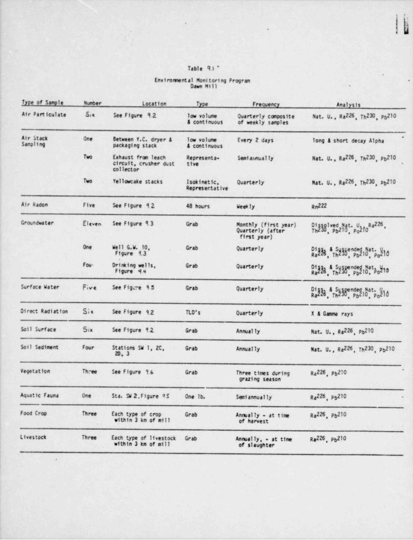
__
h
1-
.. .
Table 9.1 *
Envirorsnental Monitoring Program *
Dawn Mill *
_ Type of Sample Number Location Type Frequency Analysis
Air Particulate Six See Ffgure 9.2 low volume Quarterly composite Nat. U., Ra226. Th230 Pb210A continuous of weekly samples
Air Stack One Between Y.C. dryer a low volume Every 2 days long 4 short decay Alpha*
Sampling packaging stack a continuous
Two Exhaust from leach Representa- Samf ar.nually Nat. U., Ra226, Th230, Pb210circuit, crusher dust tive *
collector
Two Yellowcake stacks Isokinetic, Quarterly Nat. U. , Ra226, Th230, pb210Represer:tative
Air Radon Five See Figure 12 48 hours Weekly Rn222
Groundwater Eleven See Figure 9.3 Grab Monthly (first year) Of stgived Nat. U Ra226,Quarterly (after Th M ,Pb21u, poMOfirst year)
One Well G.W. 10 Grab Quarterly Of &S Nat.endg.10,p 0,Th'yFigure 1.3 Ra , Pb
Fou= Drinking wells, Grab QuarterlyFigure af.4 Ofg & Sgndej10. Eoh3Nat
Ra . . Th , Pb
Surface Water Five See Figee 1.5 Grab Quarterly &5 n t
Direct Radtation Six See Figure 1.2 TLD's Quarterly X & Gamma rays
Soil Surface Sim See Figure 1.2 Grab Annually Nat. U., Ra226, Pb210
Soft Sediment Four Stations SW 1, 2C, Grab Annually Nat. U., Ra226, Th230, Pb2102D, 3
Vegetation Th.ee See Figure 1.(, Grab Three times during Ra226, Pb210*
grazing season
Aquatic Fauna One Sta. SW 2, Figure 9.5 One Ib. Semiannually Ra226 Pb210 -
| Food Crop Three Each type of crop Grab Annually - at time Ra226 Pb210| within 3 km of mill of harvest!
Livestock Three Each type of Ifvestock Grab Annually. - at time Ra226. Pb210within 3 km of mill of slaughter
.
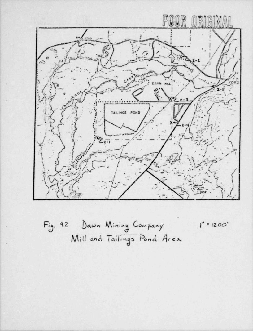
1i
j.. .- : | 1
g :-
.. ( = c s... h ;.;I..
.;
-
a ., ,,,, .r -
! --
.. . - | /..
(|. : ..' ,.,.. _ _ . , . . .r .-.
).(.._. s.?. , . > , ' . . . . . ./=s .a.pf:,.. ..c..
...
, , , . .; ... Q |-s=. .'
..- . %e.- v. - -*. *s, ). _, o'
-
_ .
(p-p3 y 2.z ,' .
'
; .. s, :. . , :.._
.I..
. .. . - .,. i.
/ .* ~
;* T., .# . s. .
'
.. ~ - , . .. ; ,,.* ... , ,
'.' ' ' . .A i f '".. ~~
s % :-Y*. 3 '- - e n'~
*
. d: ?.. . -' s ~, s. L . . -- -
*s *%g;,:.- es. .~--
5 cu:n u n* ../ s~- . Yob,
.% . - ~ 1' ,,s.' -~
.- ., . 4f.. < * *
-M '.
. ' ' ./- < t.1-5
,*: 'r -':.
-.4.= : <'-e | ,' -... .
....t s .-
. <. . 6'...-
ro s.
..'.i- .e.a j . ..- '".g,'. .
' a. * < : .'.'. ~- * .'* '' ' . ' . . . . . . . . . ' . . . . . . 2: L:.f| '.'. m.e ...* * y. |
'*
...
i ---
,.s .. r- g */r' . . ~.-
v ..D
."-
f -'.'.-
..G 3J %- ,. . |, , , . . - . -/s-.s,, .. ...J.;/ .A 1: j TAILINGS POND ' /* - ,. ~~
- ,i'.O , *,
* ,: , , , - , | .,> . ' ' .,
'*/"' *,
|ef'? y z. , . ,' '
.t.,,'~
r . .'.. i -||-' ,k *
1-
,. |.
. .
ps- +v.l. :: .
-..
.. .. v -| s, - -* -i ,.
, i- u-_ . . -.
,.->
S 7.t I. -.-.f..,.----. .. . % x t* *. -
- -
. , '.(/ . .. y * * N '
T *I |" ' *
'QJ go >'' <
.. ,
.' ' } Y,.7I .E .,,::.:-i.*''~ |" ' '
'.' ;} [)f- ,A'% & L g b-Q~ h*xy,p.,~P ].
' '' -* *
(.
i' ' '
->- ..
-+ ! . .- 1 1.g . . =. %/
p*W q\
.
.
,.e..;/ ,/*C-
.. ., ** * /\ %s ,m,e- ... -
. /. - . , . , .. .. , s . .. ,' s bs ,- </
*-/ ,s.'-g* ..., . . . ._g .- - -
; .
\...: s ....
. - - ,e -
.s. . *.y . I
- '.-p..,..
- .
- ..
N.r .: .<(l .-
-- o . ... .. .- - * . .
n, . aO ' , .z Jn-~ _ ~.. - )1, -) . .
'~.
., , t. -~
w . .: 9 ? -.
y [.
* 3 "!. ,| \; .,.
M| .& | .. ],
. . *i .
-
.
'
. Fg. u bn C& n;g ompany f = , zoo-
M;Il and Tania Pond be~C.
_. _ _ - _ _ _ - _ _ _ _ _ - _ _ - _ - _ _ -
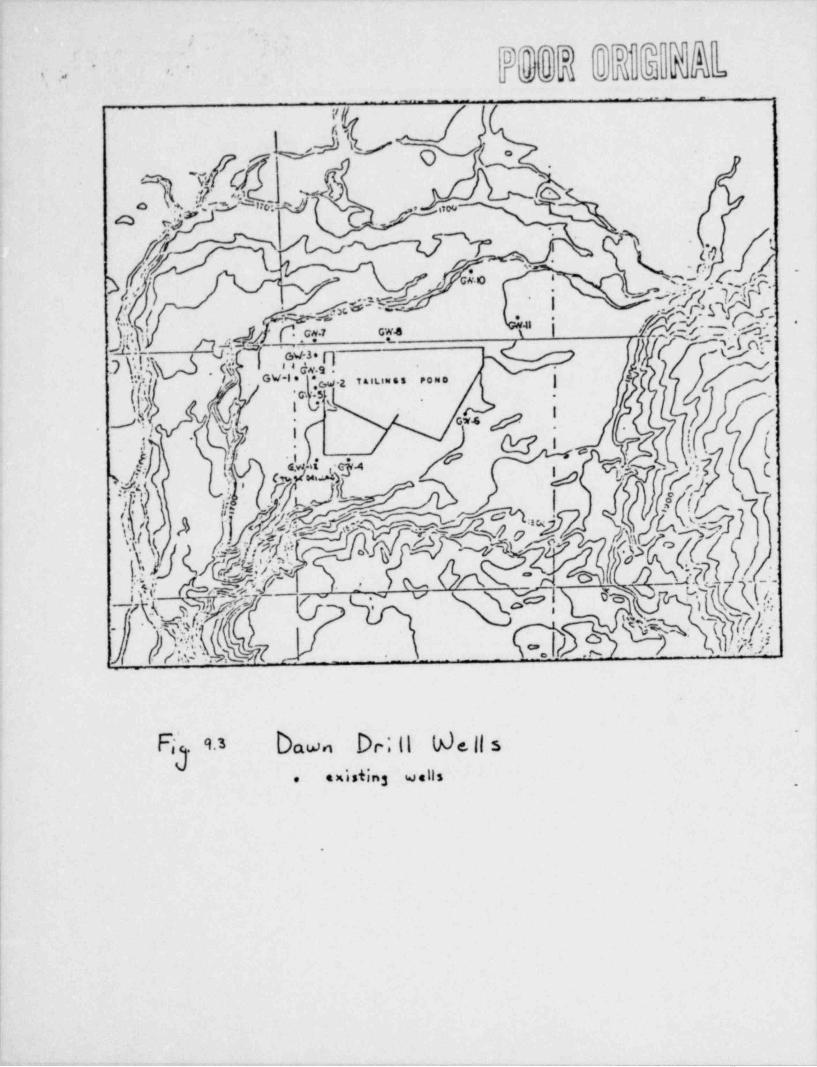
lD* * lD *'lDI T l fd
' '
f o o M o JL A AL, ,, ''' '
-
. _ _ _ __ .. .
U-- ' s -
'Io ,:>J ,..
c|[tW"T '
-
3h $4o''
-
e, ,
.
?' i
'
&_ $ -
' \i ' ,kh}$D & 'hJiy .ce ce '
i . f .,-
. u,u... ....
g -) . g .2,
,- ,.
-
, i n I' '
j oss fJ', -4
/z-)y"'
' ' ''
L cr- ,. y, -
; , .
_i- dhi _ o 0A -
[.Y 0 %5h1d!
Fij9.3 bawn Dr;H b)e||s-
.xi. s 3 w . ii,.,
'
,
|
|
- - - - _ _ - _ -_ _ _ _ _ ____

-
mDTo ai. .
$' t
J..::::*
:'q.-
,*
11
.~..(,~.... -,
i f ., .< s*. ..
. .. : I
f.~.
=::::.. .........
.
I- .
I.-,- #--
/:q.,s . I, .- .h . w. ~ ~ ~ ~ ~ ~ . ~ .
-
. s ',. . . . . -,<
..c,..
. u.~~~~ ~~~~~~~~~. ,. ' ,,' " ~L :~'.-
. f.e .:
J
l 't:r' * . .,. ** ;. ..
|. 3,
. y., Q. . . . |.' .. -.. / .g m.o~
-t- en ,,,s ...
. * / * .,.r -~~ ,... .s,
.
., ,....*
~g. .~:x :9., , -.. . .../.,- > . . . ~ . . . . , . . . . ' '
, . . ...
-.
!|
c. :,... .' .. .
g~,.?. yg.w. i . j. .,... . , ,c..:.
i,,'
.- ...
4. - yp. % ; a ... s::.r .... ....
. :. . .. .' .. . ,.. .
*.
- J-9 n 4..., .. t . . . . , . -... ,.
. , ._ 7-:.~. .jg<:
. - , .'%.
.
. . y4":.,J..Q.. s... .. '* -
,.,.7.....~.~.*. . ,. .
. . K. ,,;,,. ..
<..' '
~ R ,( &. . %g|''?',
.,,1
. ~~fY
. .
...!.- ,. ,.. ~
. s.'.> ~,,r '% s: .. : :-
: ..q...r . w s.,, . .u :;r- , . . ..
2., I-
{, ,= . n., . ,. n.. . ; ~ . ~ . . , . c.:. . .
. .,
c|| ,{ ' ;,,,f,f-''
|Af [.(cp,ppr!,..i.........*.
s' . . ' .
b-
-
|h{* ;[.;.'%:. :~',-. ,..:'.. at ~~ ~.,D~ . '' .'
'1 q'"
s:. 5.|: "< , . q ':~; e.
* g:5$.h.}-?.N .:' ::,* .;:.G....: :?..?. ?<5. h.W. :y.:. ; ././ :*., jI h 45 ' .'.| '.. -s.A.? .!' .
..cN.. .
, , ... f*r. c |*'
k i./
$sW - : 4. .' .'.
*r - ;-..
.m . ~ ; y. ' *?f< e ...,i j-
.5... *. '* *-
.,|.#' %$2:|. ' *,.~ '. < -|-
sy:. ' .' % - . . . --. - '. :,. -
. ,_ ~
. ~ , " ,v,:. s . . ,. . - .,
|1-
.
ji
,
. . . , . -. s ~ . . .. ., ., a, ,-# ,): .. [.
.fi,,,5.*)r~ -...
g:,. ,
26 . . . . .wN - |*.
/ dI~..., .~y\,
.
- p,. . . . . ;. . , ~. i. .
/, . .
.:/ y 7 ,'. . .., i.,.o
.. -- ,p..
. =::. ..''1,
. [,3
.) . J . . .,,.g.., , -
:. ,.
y .:n - ''7 a' {,. , . ,. , - , Q .: _.*. . . . .. . . .-
. . . c ..,
.
c' -. - - . .e..
. ,.,,
,e . . $.u,M ...
{ .,j.""..,...i*..
~- *
p.g('p%s .p |E .,
.
,.:.
/ *
t..-
. m. . . . . . ~ ~ ~. :. ~. ~ ~.xu . '*..' ,.|. .. . .
- (,. ~.. . -
.:. ::-~: :s. . -.
N. . g. w.:t.2k. . ~ ~ ~ '
. *, * ... :....... .
.. ~<
*%.
.: . ~.* '.. .* .X '.- . . . ' ~ ~ ~ . ng
. , ., . . . . :+-x- C\m .~ , . > ~ ,. . * ,.
'& . * 3-5 s :s y. ' t ' . .., ..- ,
. q ... P'. '
.
; - s ''.- **-
/ r(,y, .-,y. . . - . / ., '~ 'b c''3 '$ .. .. , v
.
.- *s .~~~~- ,- .. *
,'*. y~.. . . ... . \. ,; ~~! |.s %,
,.
.. ~ f;. 'E, ', .- --' , ' *-
..i 4..#
.. --' ' ' -1 ~~ .
}'.. ' e
~! . 7) %* -\ -
.
t
|.
(
Pg.9.+ ba. g"% k&g
i
|
|

@Q' 97
J WW ULk J
'- -*
.
%*
.. e. e.* ..e e s e....s e
Ei dk~~!'E5".''
"a . -.. .
# 'E
D|( Vfm~
~
SURFACE WATER SMPLING -&f-
..
-
--e
[ 9
- , " '' '~
" "~ Q / q' -/'~I,
, ,
// /,,sv s, ,
o' /*
%s -
e ....... . . . . . . .i ,,
1 b %hf |as!f wf ,-
.
h.1 WJ # f~f .
'
.
: !
.
down m;n; C o,Fig wc e. 9.5
.
|
|
_ _ - _ _ _ _ _ _ _ . _ _ _ _ _ _ _ _ _ _ _ - - _ _ =

.
.w ,
-e,r *.
. ...
T]
.T. u u u ,_r -.
, .. ~. | s
| .. . =,- ef .
*s. p
'
.| . . ' . .a,* * j :** "
, . , , * , , >-
~,..
:. . <. s, m /-
,. .,,s . .-
--% w. ..r
,,, .o .i . . , ,. ,,4. -g.
y,e.: ; , : us. ...<.
Ii pz,-s -
..e.- -
..p . .~ -
. - . . , re.----~'"\, / J
.-f
,'/o ** ~* ~~' . ! - . <[ ,- * .- i 1: ,,,; . . .
'./s|* * . . - ' ~ L - - <.\ \/
-- - .~.
s% ,g.'~f%. . k. ".', s -' - / .. m .,-
t.
9
.J.* f, - .-;- ---
" 'I I .." . "' _cg
. e. <- - ,.,
3 . *s ..h -EO*/ N '----
/ . ,* .' O AWN MILL - ''
.r-*
..
p.o | ' .7 ..-.: .- ,
4. - g.5. , .
.., -- .
a
,7. % - g . '-. . . . . --# w-'a e ,.e. s, - '., - , e ,
%,..g.s, g/
:,.f; s,,-...- --.A s ..- . '.
~* I \* '. .b. ' , ' - ' } f ''.''Y,|* i 1** *-o,.~- .- r.
, . f. ,-e ,................. . , ,
. . ; 0 .| ,f . .- ;,.
- ~.,,- . ' ' * '' '
,; } A,., '~f.;.'. ' | , /[ ' *9 '
', ,, .C1# .
M ~
~ . " ,.,, j TAILINGS POND ,' s/ <- e"
',/
* ..*.efs - .,1 .
.m; s. ./ |3f * *4 t 3
''(. .., g,
* 'i f', f' *
O ,E , ,' /, | ** * e o i.
k ' **s . '.; . .i . . . . . - -e ,f- . |s. r -. s.I f,
.
1 -[<y"r- ..|. -~\.)'* . ,.~ .
? ,_;J) W, . . . ,. *s. . .sp
. . - . - . . s. s ?. ..g. ~
4 %*| .iT *.5 , ' t h ..
y. s , $ |.
*'
j! ,,h, . iW'.5NI . I-| '|**
a '.*
'= ,,p o ,
' '
. ' ' ..-] '
\ , . ~
-~ .,/ , (.
1..: <w ' y.]] -. . f r,, . . , . . . -..
a. %~ ";-~
/ ,
~sv\. . ~ : -
,., ;-y .ry.;. .. < . ,,,,0 : . . .j. , ' '' %,. R . . ..,.?,- \
cy - - .. .< -
y\ a'
...c
_
a.,. s7*.
1 % .4 . ~. m ..' ,:,L;;. /. , - /*.' n - .s - ,%. .:~ .:. .ss
, ;. ,. g .. .,. ..
. <f- < ~ ~ - a. ,:- e. . ,y . ,,3-;; -
. s.. . ,-
.. . . . - , . .-,
- * * - . , .-pv. /- %
..-+.
. ,, n , ~ .-8. 3 .
- ~. ,.n
.-. p. ..
.f.. . * ..-
L ; g .. u- - ,.>s: .i .
, { c .1... ..
04a n-. . .
- 'w A / .,I.,a 9. . c a, -- , .,
s . f
-.
Fic . u tbn Veyhm Sap. 5;hss
.
.
l !4
1
|
|!

.__ __. . _ _ _ .__.. _ _ _ . - . _
||
10-1|
10. ADVERSE ENVIRONMENTAL IMPACTS AND MITIGATAl}LE IMPACTS*
i
10.1 Unavoidable Adverse Environmental Impacts
10.1.1 Air Quality
' The unavoidable impacts of the project construction on the air quality of the.
area should be minimal. The heavy equipment that will be operated during theconstruction phase will exhaust diesel fumes and produce fugitive dust. Bothof these effects will be temporary in nature and should be mitigated somewhat
,
by normal operating controls, i.e., wetting during the dry periods.
Offsite areas should receive only minor impact from the construction phase. -
The impacts of the project, once it is operational, should be beneficial innature when considering that the use of the freely seeping pond will be dis-continued. It is planned to keep the active tailings, of the proposed pond,completely underwater reducing dusting and radon emmanation. This differsfrom the present practice of rotating the tailings discharge line to wet thesurface of the tailings pile.
i Post Operation
With proper reclamation and cover of the tailings area, no irreversible or,
irretrievable commitments of the area's air quality should be expected.
10.1.2 Land Use
Proposal implementation will directly result in a 28-acre increase in the landsurface area now covered with uranium mill tailings. This area will be re-moved from alternate usage in perpetuity unless the tailings are reprocessedfor recovery of other elements at some future time. Note, however, that underthe terms of the Washington State Mill Licensing and Perpetual Care Act of1979, much if not all of the project site will be perpetually removed fromalternate usage regardless of project implementation by merit of its immediateproximity to a tailings disposal facility. Hence, the actual magnitude of-
this impact is small..
10.1.3 Water
' A substantial segment of the Chamokane Creek water flow, through WalkersPrairie, is subterranean; moving through the highly permeable glacial sandsand gravels of the valley floor. Emergence of this subterranean flow at largesprings in the Ford area maintains a consistent flow rate of over 25 cfs inthe lower portion of the channel. As a further consequence of the high perne-ability of the overburden gravels, no lesser tributaries to Chamokane Creekare developed in the Prairie area; essentially all precipitation and runofffrom adjacent highlands infiltrates the gravels. (Reference 50) |
|'
||
|
!
.. . - _ . _ . . _

1
|
|
|
10-2
10.1.3.1 Surface Water
Both surface waters and precipitation recharge the glaciofluvial materials inWalkers Prairie. The uppermost mantle of coarse gravels serves as temporarystorage for recharge of underlying, less transmissible materials. The effec-tive storage capacity of the glacial materials of Walkers Prairie has beenestimated at about 15,000 acre feet (Reference 50).
.
Installation of the impermeable liner system will result in a loss of 28 acresof precipitation infiltration surface, resulting in a slight decrease in'
ground water quantity derived from this source area. Because of the large .
volume of groundwater available in the alluvial aquifer and its large rechargecapacity, the loss of precipitation due to tailings pond capture is not con-sidered to represent an irreversible or irretrievable commitment of thisresource.
Major flooding will not encroach upon the project area as the stream channellies in a wide meander valley, a full 100 feet below the project elevation.
10.1.3.2 Groundwater
Occurrence and movement of groundwater in the Walkers Prairie area around theDawn Mining Company complex is discussed in some detail by Woodward (1971).Water resource data are available from the U.S. Geological Survey on the flowin Chamokane Creek and on water levels in the R.D. Seagle well along ChamokaneCreek. These latter data indicate an annual cycle of water level variation,with highest levels during May and lowest levels during November.
Possible exposure pathways to the general population via the groundwatercomplex are:
1. Radioactive and toxic materials from the tailings ponds leached intothe groundwater.
2. Centamination of food through uptake and concentration of toxic elementsby plants and animals.
While theoretically the proposal is a zero-seepage facility, the potential for -
liner leakage certainly must be recognized. However, the occurrence of anysuch seepage will be detected by the leak detection system and mitigatingmeasures will be taken. .
Implementation of the proposal will permit immediate termination of the use ofthe existing, freely seeping tailings disposal complex. This should result ininterruption of seepage recharge, diminution of hydraulic head, and dissipa-
, tion of the phreatic mound. Mill tailings effluent now slowly migrating
| should be effectively stranded in the dried vadose zone.
|
|
|__
-_ _
10-3
10.1.4 Soils (Also see Sec. 8.5)
fonstruction
Construction of the tailings pond would permanently remove about 50 acres ofthe site's soils from productivity. The topsoil removed during constructionwould be stored; however; topsoil storage does not automatically ensure thatProductivity of the stored material is retained. It is also likely that some
.
of this material would be lost because of wind and water erosion during the 13to 15 years of storage. Construction of the tailings pond should cause nomajor impacts to soils outside the site. Increased grazing by animals dis-placed from the construction site probably would cause some small additional*
soil compaction and erosion in the areas to which the animals move.
Operation
During continued operation of the mill, impacts to soils of the site couldresult from seepage of solution from the tailings impoundment. Solutionseepage should be considered only in the event of a liner rupture.
Post Operation
Some of the soil removed from 50 acres during construction of the tailingsimpoundment and subsequently stored during mill operation would be lost througherosion during the storage period. That material remaining would be placed asearth cover to aid revegetation during reclamation procedures. No additionalsoil losses or impacts would occur after operation ceases, unless previouslyundisturbed soils were removed for reclamation of the mine or mill sites.
10.1.5 Biota (References 15, 42)
10.1.5.1 Terrestrial
Construction
Construction of the tailings pond would result in a reduction in the totalproduction on the site. The loss of small-ma=ual biomass on the 50 acresaltered by construction would include ground squirrels, deer mice, and red.
squirrels. The significance of these losses to the regional ecosystem isbeyond present assessment capabilities; however, these losses would be similarto those from construction of other industrial or commercial installations in
I the same area and involving the same amount of land.-
Bird populations would be impacted by the loss of rodents serving as food |sources for raptors, by loss of seed sources, which comprise about 30 percent '
of food sources for non-gamebirds of the site, and by loss of invertebrates,which comprise 70 percent of the diets of dominant bird species. In addition,loss of vegetation would reduce the available nesting habitat. (See Section8.6.1)
;
1|

1
!
|
l,
10-4
Operation
Biota could be affected as a result of seepage of potentially toxic elementsfrom the tailings impoundment, or from purposeful or accidental releases oftailings solution outside the impoundment. (See Sec. 8.6.1)
Toxic elements could also be ingested through the food chain. The soila ofthe site are mainly sandy loans with relatively low cation-exchange capacity .
and thus would have little retention capacity for some toxic cations. In'
addition, although absorption of an element by the soil exchange complex wouldtemporarily exclude it from entering the groundwater, it would not exclude it ,
from entering the food chain via uptake by vegetation. The accumulation inforage vegetation could be toxic to the herbivores.
Summa ry
The major impacts to terrestrial biota would arise from removal of habitat andfrom contamination of forage with potentially toxic elements. However, theseimpacts should be greatly reduced or eliminated. (See Sec. 10.2)
10.1.5.2 Aquatic
The presence of certain heavy metals, radionuclides, and other toxic chemicalby-products of mill operation may currently exceed background concentrations inthe receiving stream. Implementation of the proposal will halt fresh influxof solutions to the substrate. Subseque?.t diffusion, dilution, and attenu-uion by soil reactions should eventually eliminate the areas of excessiveconcentrations of those substances.
10.1.6 Radiological (See Section 4 of the Environmental Impact Statement)
Radiological impacts not discussed in Section 4 are discussed below:
10.1.6.1 Soils
Construction will have no unavoidable adverse radiological environmentalimpact. No radioactive materials will be involved during the constructionphase. (See Sec. 10.2.4) -
10.1.6.2 Biota (Reference 15)*There will be radiological impacts on species other than humans within the,
' region; however, no exposure pathways have been identified which are differentthan, and would result in another species receiving does signficantly above,those calculated for man outside the site. The dose rates and doses to animalsliving in the region of the mill are expected to be low enough that any dele-terious effects would be manifest only af ter a long latent period. Since thelife span of most animals is rather short, and populations in the wild aresubjected to high attrition rates, the effects of radiation from the tailings
|
|
|
|'
__ _ - - . _ _ _ _ _ - __ D

|
|
|
|
10-5
,
pond would not be distinguishable from other naturally occurring forces. '
Although guidelines have not been established for acceptable limits for radia-tion exposure to species cther than man, it is generally agreed that thelimits established for human beings are also conservative for other species.The BEIR Report concluded that the evidence to date indicates that no otherliving organisms are very much more radiosensitive than man.
It is possible that animals living onsite, in or close to the tailings pile,.
might be subjected to doses that are high compared to those that could resultoffsite. However, a relatively small proportion of the individuals within theregion might thereby be affected, and the total impact on the local biota
* therefore is expected to be small.
10.1.6.3 Community
Construction
Inasmuch as no radioactive materials would be used in the construction of thetailings pond, there would be no nontransient radiological impacts resultingfrom such construction. A possible transient effect might rusult from distur-bance of the land and ground cover, such as in excavation and roadbuilding.These activities would add incrementally to releases of fugitive dust andpossible slightly increase radiation exposure from this source; however, thedust raised would be of the same composition as the background dust, so anyeffect would be small, and probably undetectable. In comparison to the radio-logical impact during and after mill operation the radiological effects ofconstruction are negligible.
Operation
The principal pathways by which radioactivity may reach human beings andirradiate their tissues include: (1) direct, external exposure from radio-nuclides in the air or on the ground; (2) inhalation of radioactivity into thelungs, possibly followed by redistribution to other organs of the body, and
'
(3) ingestion of radioactivity in foodstuffs. The inhalation and ingestionpathways result in the radioactive material being deposited inside the bodyand irradiating it from within. Accordingly, doses received via these path-ways are referred to as internal doses so as to distinguish them from radia-.
tion received from sources external to the body. In general, members of the
| public outside the mill boundary would receive no significant direct, externalexposure from radioactive materials which remain onsite in storage. (Referencei
! 15 and Section 4)-
| Post Operation
The project-related radiation exposure within the region in each year followingshutdown of the mill will primarily depend on management of the tailings pile.
,This is because the air concentrations of all radionuclides except U238 and U-
| 234 originate principally from the tailings. Mill shutdown, including cessa-| tion of yellowcake drying and packaging, will effectively eliminate about 84| percent of the uranium particulate sources, but only about 2.5 percent of the
_ _ _ __- . - - - -

. - ,
10-6
.
thorium and even less of other nuclides. This would reduce the total dosecmunitments to the organs of nearby residents only negligibly (except for lungand bone doses from particulate inhalation) and would have an insignificanteffect on population doses.
,
Following shutdown of the mill, the annual dose commitments to the populationwithin an 80km (50 mile) radius will de~ crease and remain at less than about onepercent of the population doses from natural background. (Reference 15 and -
Section 4)
10.1.7 Socioeconomic .
IMPACT OF PROPOSAL ON ELEMENTS OF THE hTMAN ENVIRONMENT
Implementation of the proposal will simply permit a continuation of existingpatterns. New jobs will be created only during the short-lived constructionphase and are expected to be filled by present employees of the selectedproject contractor.
Since virtually no changes in the human status quo will result from the pro-ject, the impacts under every heading of the existing human environment arenil.
Only the "no action" alternative would result in alterations to the localhuman status quo. In this case about 130 present jobs would be lost. Thisrepresents a highly significant impact of that alternative to the area.
Similarly, such features of the human environment as aesthetics, recreationalopportunities, and archaeological / historical resources will not be.affected bythe project. The site is fully shielded from public view and will thereforenot affect the aesthetic values of the area. Restricted access (already ineffect) precludes utilization of the site for recreational purposes, and nofeatures of either archaeological or historical importance have been identi-fied, despite the extensive work previously undertaken in the project vicin-ity.
, SUMMARY OF IDENTIFIED IMPACTS,
.
Because of the narrowly restricted nature of the actual proposal, the poten-tial areas of impact are few. After intensive review over 12 months time, nomajor social adverse impacts have been identified. On the contrary, the most ,
significant impacts expected appear beneficial. (See Sec. 10.2.3) The mostsignificant nonsocial impact is that of land-use restrictions imposed by RCW ,
70.121. l
10.2 Adverse environmental impacts which may be mitigated
___ _ _ _ . .

_ _ _ _ . _ _ _ _ . _ _ - _
10-7
10.2.l Air Quality,
Construction
The only potential impact anticipated during construction operations is dust-ing. Sprinkling by means of a water truck will be utilized as needed to con-trol this potential impact on air quality.
.
Operations
The subgrade disposal system here proposed will be essentially free of dusting',
*potential due to a rapid build up of solutions that will either cover orsaturate the tailings solids. No discernable odors or other air impacts areanticipated.
Post 0perations
After placement of a stabilization cap and establishment of the rock cover,there should be no furthet potential of air quality degradation. (See Sec.10.2.6)
10.2.2 Land Use;
Foreclosure of future land-use options appears to be the most irreversible andlasting impact, of those discussed in this statement. Mitigation of thiseffect as much as possible was a stated goal of the disposal option design.Since the facility will be excavated to the maximum depth permitted by the
'position of the water table, its capacity relative to surface area is at a
'
practical maximum.
The only disposal alternative that would avoid incremental increase in theforeclosed-usage surface area whould be a lift of about 20 vertical feet aroundthe entire above-ground dike system now in use. While this approach would
' mitigate the land-use foreclosure problem, it would sustain the more solutionseepage aspect of the present system. Also, it would place the tailings in aconsiderably more vultierable position for erosional breeching of the coverlayer in the long-ters. (Reference 1)
.
10.2.3 Water ,
Solution seepage of the present tailings disposal system, would be greatly,
| mitigated by implementation of the proposed fully-lined facility.-
|| Implementation of the proposal will permit immediate termination of the use of| the existing, freely seeping tailings disposal complex. This will result in
j interruption of seepage recharge, diminution of hydraulic head, and dissipa-; tion of the phreatic mound. Radionuclide species now slowly migrating will be| effectively stranded in the dried vadose zone. Eventual upgrading of seepage-
|contaminated groundwaters is expected to ensue.
l
|
. - _ - _- _ . _-. _ - ._. - _ -

10-8
Implementation of the proposal should eliminate seepage discharge from theexisting tailings pond. The proposed system is capable of storage of allsolids and liquids generated for several years. However, to derive fullutilization of solids storage capacity, the company must devise either (1) asupplemental system for liquid disposal, or (2) a means of recycling processliquids to reduce discharge rates to a level that can be accommodated bydirect pond evaporation.
.
Thia problem is currently being studied in detail by the company. It isprobable that systems will be devised to recycle a significant fraction of theprocess liquids, which will have the potential significant impact of reducing .
fresh water requirements for milling operations.
10.2.4 Soils
Maintaining tailings surfaces wet with tailings solution or by sprinkling themwith water can suppress dusting. This can be accomplished, for example, byarranging the discharge of tailings slurry to occur from multiple, as opposedto a single-point, discharge so that a wide area of the tailings surface re-mains wetted. Alternatively, sprinkling systems, tank trucks, or chemicalsupressants could be employed to spray dried areas. Because surfaces of thetailings impoundment can dry out rapidly, particularly on dry and/or windydays, this method of dust suppression will require continuous managementattention.
However these methods should not be needed for long due to the expected rapidbuild-up of liquids as previously discussed.
There are two alternatives for capping the tailings area, revegetation androck cover. The topsoil, which will remain in storage, Sec. 10.1.4, should beprotected from the erosional forces. Chemical suppressants can be used tomaintain the soil until natural vegetation has had sufficient time to develop.On the other hand the NRC has recommended the use of a rock cover instead ofrevegetation as there is little topsoil and perpetual maintenance of rockcover costs less in the long-run.
10.2.5 Radiological.
Pursuant to the Washington State " Mill Licensing and Perpetual Care Act of1979" and based on the guidelines presented in NUREG 0511, Draft GenericEnvironmental Statement, Dawn has developed the reclamation plan as outlined . ,
in Section 3.1.5. It is recommended that natural reforestation p. 39 be jdiscouraged and instead a rock cover substituted. The deep and extensive rcotsystem of large trees could compromise the integrity of the clay cap.
10-9
*10.2.7 Society
Mitigation of impacts, to the community, would only be necessary if the expan-sion project is delayed or totally disallowed. By authorization of the pro-posal, milling operations at the Dawn facility will be able to continue,ultimately preserving over 130 jobs for a period of 6 to 10 or more years.During that period 2.5 to over 4 million pounds of yellowcake will be pro-duced, significantly contributing to the nation's electrical energy production.
in a time of pointed attempts to achieve national self-sufficiency in energyresoorces.
The only mitigating option, other than those already mentioned, would be that*
of the "No Action" alternative.
It is a peculiar feature of the proposed system, that the "no action" alter-native, that is, non-issuance of permit, resulting in termination of mill opera-tions appears to generate greater impact to the community than would implemen-tation of the proposal. The key consideration in this context is the sourceof the considerable volumes of burrow materials required for the reclamationand stabilization of existing (and any new) tailings disposal facilities.
(Reference 1)
The proposed excavation will generate an amount of sands and gravels adequateto cap all facilities and moderate outslopes. Utilization of this pit fortailings disposal will effectively restore the topographic form of the exca-vation.
If the "no action" alternative were pursued, a burrow pit equivalent in volumeto that of the present proposal would have to be excavated to obtain reclama-tion materials for existing facilities, or that amount of materials would haveto be trucked to the site. (Reference 49)
,
o
9
%
1'
i
i
1
|
11-1
11. RELATIONSHIP BETWEEN SHORT-TERM USES OF THE ENVIRONMENT ANDLONG-TERM PRODUCTIVITY
11.1 Environment
11.1.1 Air Quality
Air is generally considered to be self cleaning because of its dynamic nature.,
No lasting effect will impair long-term productivity of this resource, althoughit must be mentioned that Radon-222 emmissions will be a continuing event.Mitigation of these emmissicas, during operation and post operation phases,will essentially negate any consequence which normally might occur. (See Sec.*
10.2.6)
11.1.2 Land Use
The local, short-term effects of continued milling are those associated withthe operation of any comparable sized ore milling facility. The short-termdisruption of the landscape during mill operations will not adversely affectlong-term aesthetics if reclamation efforts are successful as planned. Themillsite will be returned to its prior uses without restriction, except forthe tailings disposal area, which will require perpetual restrictions againstdigging or other forms of intrusion that could expose the buried tailings.Proposed reclamation measures should permit otherwise unrestricted access andland use in the longterm.
.
11.1.3 Water
All water requirements for the continuing operation are satisfied by naturalsprings. Long-term effects on groundwater quality are not expected from exist-ing tailings impoundsents, as implementation of the proposal should preventany further seepage influx into the aquifer. Dilution, diffusion, end chemicalattentuation by soil reactions rhould reduce presently affected groundwatersto ambient conditions.
11.1.4 Mineral resources
The mining and milling of uranium ores does not preclude extracting other,
substances of future economic importance should the demand arise. The uraniummill tailings could be easily reworked. 9owever, the provisions of RCW 70.121preclude such extraction.
.
11.1.5 Soils
An additional lasting effect would be to soil, which will be lost to erosionprior to reclamation of the tailings area. Erosion, a natural process, willbe impacting the soils of the site even if the "no action" alternative isadopted. The added impact to the soil involved in expanding the tailings pond j
'should be minor.'
|
||
|,
I
|- - _ _ _ _ -

.- - .-- . - - . . . . . . _ - - - . .__ _ _ .
i,
|'
11-2
,
j
11.1.6 Biota
Milling activities to date have reduced or eliminated the viability of about220 acres of open pine forest vegetation and wildlife habitat. Implementationof the proposal will result in the inclusion of an additional 50 acres thatwould not otherwise be disturbed. However, final reclamation plans call for
,- reestablishment of native vegetation after cessation of operations which
should be followed by the return of native faunal species. Long-ters produc- ,
tivity and diversity of faunal communities should return to a state approxi-.
mating undisturbed surrounding areas. Floral distribution should be disturbedonly in the area of rock cover.
*;
11.1.7 Radiological
State of Washington Regulation WAC 402-50-020 states that " Sufficient naturalcover shall be placed over tailings or wastes at the end of milling operationsto result in a calculated reduction in surface exhalation of radon from thetailings or waste to less than two picocuries per square meter per secondabove natural background levels". The minimum allowable depth of cover isthree meters. Earth cover of this magnitude would reduce gamma radiation tobackground levels. The Washington state regulations reflect identical require-ments proposed by the NRC in admendments to Appendix A to Part 40 Title 10Chapter 1. In light of this it can be said that the reclaimed tailings areawill constitute a source of radon emmission at about twice the natural back-ground flux. Gamma radiation will be reduced to background levels.
When Dawn filed its original license renewal application, July 1979, and*
committed itself to two feet of clay and sufficient earth to bring the coverand federal regulations had not been
to three meters in depth, the final statg/sec standard has been set.arrived at. Since that time the 2 pCi/m Usingthe method of calculation used in Appendix P in NUREG-0511 Generic EnvironmentImpactStatement, April 1979,Dawncalculatedtheradonemanationtobeexpecgedif two feet of clay plus earth to a depth of 3 meters was used at .0089 pCi/m /sec.The extremely low emanation rate indicates a case of over design. In light of *
the lack of locally available clay and its high cost to import, Dawn calculatedthe depth of cover required if only native soils were used. This depth, 18.12feet, represents a large increase in material required for reclamation butbecause of lower materials cost would actually be less costly than the clay /.<
.
! earth combination. Several combinations of clay and soils were looked at but! all were eliminated because of high cost. Battelle Northwest Laboratories is
! conducting laboratory and field studies on radon emanation and attenuation by( various cover materials specific to the Dawn site. When final results frou -
this study are available a more accurate calculation can be made of the depth|'of cover required, i.e., use actual porosities and bulk diffusion coefficients.(Reference 58) Meanwhile DSHS is proceeding to implement the three meter,
standard.>
{o
a
_ ____._ _ _

11-3|
11.2 Society
The tailings expansion should have no long-term impact on the surroundingcommunity in addition to that already realized by the present milling opera-tion. The greatest impact to the community will probably occur when the millis decommissioned, 10 to 15 years in the future.
This region is basically oriented toward farming with few other mine related*
jobs available. There is another uranium mine and mill within 30 miles of theDawn project; it is probable that not enough vacant positions would be avail-able to absorb Dawn's present work force. A gradual reduction of employees.
throughout a lengthy period would have to be undertaken in order to eliminateadverse impact to the community, if it was found necessary to cease millingoperations.
.
i
9
|.
- - __

I
|
|1
!!
12-1 ;
.
12. IRREVERSIBLE AND IRAETRIEVABLE COMMITMENTS OF RESOURCES
.
12.1 Land and Mineral
Land
A restriction on digging or other forms of intrusion may indefinitely prevent.
the development of the lands containing buried tailings. This is consideredan irreversible commitment of resources.
*
Mineral
The extraction, processing, and eventual use of the ammonium diuranate pro-duced by the mill are considered irreversible and irretrievable. Except forthe uranium extracted, little commitment of mineral resources are anticipated.(See Sec. 2.1)
12.2 Water and Air
The expected releases of chemical and radioactive materials have been dis-cussed in preceding sections. During and after milling operations, both airand water resources are used to bear these discharges. There is, therefore, acommitment of these resources for this purpose. These commitments, however,are neither irreversible nor irretrievable although they may extend for someperiod of time after operations cease, as may be the case with groundwaterimpacts.
.
12.3 Biota
Terrestrial
The area of the tailings pile will not be available for any activity that willresult in the incorporation of the tailings into the upper strata of the soilor in any way damage the seal over the tailings. The possible effects ofbreaching of the soil and clay materials by burrowing animals is not known;however the placement of the rock cover, as recommended, should minimize thissituation.-
Aquatic ;
I
The presence of certain heavy metals, radionuclides, and other toxic chemical |'
by products of mill operation which now exceed background concentrations in |
Chamokane Creek should be slowed and eventually eliminated after the proposalis implemented.
11
12-2
l
!12.4 Material Resourcesl
Chemicals and reagents (See Table 2.1) required by the milling process will be'
consumptively used, and therefore are considered irretrievable and irrevers-ible commitments of these resources. Use of these materials is considered animpact, because of the volumes consumed. These materials are readily avail-able, at this time no shortages are presently foreseen. (Reference 52)
.
O
I
ee
e
e
e
I|
||!
|
| |1
.--___-___________ _ _ __-___ - _ _ _ _ .
. . . .
G,
@3.I
I ,~-
' a6
d 0 03tr on( )5
7 @86 Months
Payments 1956-1963 1969-19/7 1978 1979 1980 Total 8gWages 1,385,377 4,411,060 851,422 1,085,654 * 620,008 8.353,521 X7~
%q{Royalties 2,000,132 4,692,397 334,962 1,263,116 419,673 8,710,280
$ Federal Income Tax 7,692,100 9,941,803 2,093,729 1,642,710 558,216 21,928,558
h Property Tax 310,089 218,795 19,877 39,792 14,919 603,472 }~ gh FICA (Social Security) 66,692 240,218 51,148 66,098 37,761 461,917
.,
$ FUTA (Fed. Unemployment) 6,602 10,739 1,462 5,025 1,504 25,332
4 $UC (State Unemployment) 41,862 74,397 18,104 18,169 9,122 161,654 x*O 8 3 0 Tax (State) 179,458 296,345 47,220 50,402 27,346 600,771 b
hpC 3 M Tax (Uranium Mill Tax> .
State) -0- -0- -0- -0- 9,220 9,220 g3DSHS (Environmental Monitorin9 3q
Fee) -0- -0- -0- -0- 45,000 45,000 .y-
Sales Tax (State) 185,546 298,498 53,746 62,134 36,924 636,848 f '
41,536,573 pE3
.
e

REFERENCES
1. Dawn Mining Company (1979), " Tailings Disposal Facility Expansion Project,Environmental Impact Statement."
2. S. T. Algeraissen and D. M. Perkins, "A Probablisitic Estimate of IMaximum Acceleration in Rock in the Contiguous United States," U.S. |
Geological Survey Open File Report 76-416, 1976.,
3. Golder Associates (1979), "Geotechnical Design Data, Proposed Tailings ),
Disposal Facility Expansion", Dawn Mining Company, Ford, Washington
4. Bolt, B.A., et al., (1977), Geological Hazards, Revised 2nd Edtion,* Springer-Verglag.
5. " Draft Environmental Statement, Sherwood Uranium Project, Spokane, IndianReservation," U.S. Department of the Interior, Bureau of Indian Affairs,Portland, April 1976.
6. U.S. Bureau of Reclamation (1977), Design of Small Dams, Revised ReprintA Water Resources Technical Publication.
7. U.S. Nuclear Regulatory Commission,1977, " Design, Construction, andInspection of Embankment Retention Systems for Uranium Mills," RegulatoryGuide 3.11.
8. Dawn Mining Company (1980), " Response to N.R.C. Questions.".
9. Sherard, J. C., et al., (1963), Earth and Earth-Rock Dams, John Wiley andSons, Inc., New York.
10. Peck, R. B. , Hanson, E.W. , and Thornburn, T.H. (1974), FoundationEngineerina, Second Edition, John Wiley and Sons, Inc., New York.
11. Dawn Mining Company (1980), " Response to E.P.A. Comments on TailingsDisposal Facility Expansion Project."
12. CANMET (1977), " Pit Slope Manual," Energy, Mines, and Resources, Canada,Ottawa, Canada.
.
13. Nelson, John D., and Shepherd, Thomas A., (1978), " Evaluation of Long-Tern Stability of Uranium Mill Tailings Disposal Alternatives," for ArgonneNational Laboratories, Contract No. 31-109-38-4199.
,
|
|.

_ . . . .
R-2
14. Creager, W.P. , Justin, J.D. , aat !!!wA, (1945), Engineering for Dams,*-
> sJohn Wilery and Sons, New York,
- 15. " Generic Environmental Impact St4tement on Uranium Milling" (Draft),U.S. Nuclear Regulatory Commission, NUREG-0511, April 1979, Project M-25.
16. Letter from Mr. Jack E. Thompson, Dawn Mining Company to Mrs. NancyKirner, DSHS, State of Washington, August 12, 1980. -
17. " Environmental Survey of the Uranium Fuel Cycle," WASH-1248, U.S.Atomic Energy Comnissioa, Fuels and Materials, Directorate of Licensing,
,
April 1974.
18. Letter from Mr. T. R. Strong, DSHS, State of Washington to Mr. R.Scarano, NRC, March 26, 1980.
19. U.S. Nuclear Regulatory Commission, "Calcul&tional Models for EstimatingRadiation Doses to Man from Airborne Radioactive Materials Resulting fromUranium Milling Operation," Task RH 802-4, May 1979.
20. C.C. Travis et al., A Radiological Assessment of Radon-222 Released fromUranium Mills and Other Natural and Technological Enhanced Sources,NUREG/CR-0573, ORNL-NUREG-55 Oak Ridge National Laboratory, February 1979.
21. B.R. Metzger, " Nuclear Regulatory Commission Occupational ExposureExperience at Uranium Plants," Conference on Occupational Health Experiencewith Uranium, Report EkDA-93, Washington, DC, 1975.
22. Fuel Processing and Fabrication Branch, U.S. Nuclear Regulatory Commission,Presentation to the Environmental Subcommittee of the Advisory Subcommitteeon Reactor Safeguards, Occupational Radiation Exposure control at FuelCycle Facilities, January 26, 1978.
23. S.I. Auerbach, " Ecological Considerations in Siting Nuclear Plants.The Long-Term Biota Effects Problem," Nucl. Saf. 12:25-35 (1971).
24. Proceedings of the Environmental Plutonium Symposium, Report LA4756,Los Alamos Scientific Laboratory, Los Alamos, N. Mex. ,1971, and -
A Proposed Interim Standard for Plutonium, Report LA-5483-MS, LosAlamos Scientific Laboratory, Los Alamos, N. Mex. 1974
25. Enewetak Radiological Survey, USAEC Report NV0-140, Nevada Operations *
Office, Las Vegas, Nevada, 1973.
26. N. A. Frigerio, K. F. Eckerman, and R.S. Stowe, " Background Radiationas a Carcinogenic Hazard," Rad. Res. 62:599 (1975).
27. A. H. Sparrow et al. , " Chromosomes and Cellular Radiosensitivity,"Rad. Res. 32:915 (1967).
,

R-3
28. Radioactivity in the Marine Environment, Report of the Committee onOceanography, National Academy of Sciences-National Research Council,Washington, DC, 1971.
,
29. R.J. Garner, " Transfer of Radioactive Materials from the TerrestrialEnvironmengtoAnimalsandMan," Environ. Control 2:337-85, 1971.
30. S.E. Thompson, Concentration Factors of Chemical Elements in Edible,
Aquatic Organisms, USAEC Report UCRL-50564, Rev. 1, October 1972..
31. " Principle Parameters for Radiological Assessment," Dawn MiningCompany, May 1980.
,
32. " Descriptions of United States Uranium Resource Areas," a supplementto the Draft GEIS, Argonne National Laboratory, NUREG/CR-0597, ANL/ES-75,June 1979.
33. " Tailings Management Plan Evaluation, Dawn Mining Company, Ford,Washington," for U.S. Nuclear Regulatory Commission, by John D. Nelsonand Steven R. Abt, Colorado State University, August, 1980.
34. International Atomic Energy Agency, Safety Series No. 43, Manual onRadiation Safety in Uranium and Thorium Mines and Mills, IAEA, Vienna 1976.
35. " Recommendations of the International Commission on Radiological Protection /Report of Committee II on Permissible Dose for Internal Radiation," (Health Phys., 3:1-380, 1960.
36. " Deposition and Retention Models for Internal Dosimetry of the HumanRespiratory Tract," ICRP Task Group on Lung Dynamics, Health Physics12:173-205, 1966.
37. " Recommendations of the International Commission on Radiological Protection,"Report of Committee 4 on the Assessment of Internal contamination Resultingfrom Recurrent or Prolonged Uptakes, ICRP Publication 10A, Pergamon Press,London, 1971.
38. Bade, C.F., Ford, WA Postmaster and Fire Chief, Personal Communicationswith N. J. Lehrman, Dawn Mining Co, 1979.-
39. Borror, D.J., and White, R.E., 1970, A Field Guide to the Insects ofAmerica North of Mexico; Houghton Mifflin Co, Boston.. ,
l'
40. Daubenaire, R., and Daubenaire, J.B., 1968, Forest Vegetation ofEastern Washington and Northern Idaho. Washington AgriculturalExperiment State Technical Bull. 60
41. Hill, Don R. , and Younberg, Elton A. ,1977, " Stabilization of Tailingsand Decontamination of Mill Site," a report for Dawn Mining Co. nearFord, Washington.

_ _ . ._ _ . - _
R-4
42. -Larrison, E.J., 1970, Washinaton Mammals. The Seattle Audubon Society, iSeattle, WA |
43. Larrison, E.J., and Sonnenberg, K.G., 1968. Washington Birds. TheSeattle Audubon Society, Seattle, WA
44. Miller, F.K. , and Clark, L.D. ,1975, Geology of the Chewelah-Loon Lake Area,Stevens and Spokane Counties, WA, U.S. Geological Survey Professional .
Paper 806.|!45. Spokane Indian tribal Employment Rights Office, Personal Communications
'
July 1980
46. Stebbins, R.C., 1966. A Field Guide to Western Reptile and Amphibians.
Houghton Mifflin Co. Boston
47. State of Washington, Office of Financial Management, Population, Enrollmentand Economic Studies Division " State of Washington Population Trends" (1978)
48. Washington State Department of Ecology,1973, " Draft Environmental ImpactStatement," Proposed Northwest Alloys Magnesium Plant, Addy, Wa.
49. Washington State Legislature,1979, " Mill Licensing and Perpetual CareAct of 1979;" Substitute Senate Bill No. 2197.
50. Woodward, W.L., 1971 "A report of an Inventory and Study, Water Resourcesand Utilities (Spokane Indian Reservation)." Consulting report preparedfor the Spokane Tribe of Indians.
51. Wynecoop, D.C., 1969, Children of the Sun: A History of the SpokaneIndians. Comet and Cole, Spokane, WA.
52. Dawn Mining Company, Application for Radioactive Materials LicenseWN-1043-1 July 31, 1979.
53. USNRC, Regulatory Guide 4.14 (Revision 1). Radiological Effluentand Environment Monitoring at Uranium Mills Apri). 1980
.
54. USNRC, NUREG-0505 Environmental Statement Sw..twater Uranium ProjectDecember 1978
i
! 55. USNRC NUREG-0451 Environmental Statement Split Rock Uranium Mill -
November 1978
! 56. Associated Taxpayers of Colorado, Personal Communication, March 1980.
|
.
_ _ _ . _ _ _ . _ _ - . - _ . - _ -.
.
R-5
57. Spokane Tribe, Planning Department, Personal Communication, March 1980.
58. Dawn Mining Company, 1980, " Response to DSHS Question."
59. USNRC, NUREG-0556 Environment Statement White Mesa Uranium Project,May 1979
60. Wilson, Lee C. and Rouse, Jim V., Envirologic Systems Inc., "Geohydrologicaland Geochemical Evaluation of Existing and Potential Contaminant Transport-
from Dawn Mining Co. Tailings Pond, Ford, Washington."May 2, 1980
.
61. Letter from W. R. Lawrence, Mill Superintendent, Dawn Mining Company toArden Scroggs, DSHS, State of Washington, September 26, 1980.
62. Letter from Ronald E. Versaw, Golder Associates to Dawn Mining Company,November 5,1980.
63. Letter from J. E. Thompson, Resident Manager, Dawn Mining Companyto Nancy Kirner, DSHS, State of Washington, October 31, 1980.
| 64. " Dawn Mining Company Response to NRC Environmental Assessment of the' Dawn Mining Campany Proposed Below-Grade Tailings Management Plan,"
September 14, 1980.
65. " Dawn Mining Company Contract No. C1, Excavation and Lining TailingsDisposal Project," October 1980.
66. Letter from Ross A. Scarano, Chief, Uranium Recovery Licensing Branch,US NRC, to Nancy Kirner, DSHS, State of Washington, December 3,1980.
67. Report: Environmental Radiation Program,18th Annual Report July 1978 -1979, Department of Social and Health Services, State of Washington.
.). -
.
|
|
.

D
APPENDIX A
CALCULATION OF SOURCE TERM
.
O
%
e
|
|
|1i
.-__ _ _ _ _ _

.
A-1 .
. --.
.
Introduction .
The radiological assessment for the operation of the Dawn Mining Companyuranium mill was performed using the MILDOS computer code. The input to thecomputer code consists of site-specific data and staff estimates of the radio-
~active effluents from the mill and tailings management systems. These sourceterm calculations for the tailings impoundment are described in Appendix B. !
Source terms are defined a3 the estimated quantity of radioactivity released !
in a specific period of time.,,
-
IThe mill sources addressed in.this appendix are: -
1. The ore pad and its relatid activities.2. Mill hoppers and feeders.3. Grinders and crushers. ,
4. Fine ore storage and transfer of fine ore.5. Yellowcake drying and packaging.
Some general parameter values which are necessary to these calculations are:
1. The annual ore processing rate is 148,500 MT/ year.1. The ratio of radioactivity in the ore dust to that of the bulk ore is 2.5.3. The bulk ore activity for U-238, Th-230, Ra-226, and Pb-210 is 432 pCi/gm.
Ore Pad Activities
Particulate emissions from the ore pad are the result of:,
1. Truck delivery of ore.2. Ore pad handling by front-end loaders and other equipment.3. Windblown emission.
Radon gas emissions are estimated on a specific Rn-222 flux (Ref. A.1) of2pCi/m -sec Rn-2221.0 .
pCi/gm Ra-226'
1. Truck Unloading -
1
The release rate is estinated by the staff to be (Ref. A.2): .
-
0.1 lb/ ton = 0.1/2000 = 5 x 10 5 release fraction
The particulate release is then:-
148,500 MT/ year x 10s gm/MT x 2.5 x 10 12 Ci/pCi.
~ ~
x 5 x 10 5 x 432 pCi/gm = 8.04 x 10 3 Ci/ year
i
|
|
I'i
_ _ _ _ _ _ _ _ _ _ _ _ - - _ _ _ _ _ - _ _ _ _ _ _ _ _ _ _ - - _ _ _ _-

l
~
A-2*
.
2. Handling .
\*
The release rate is estimated to be (Ref. A.2):~
0.05 lb/ ton = 0.05/2000 = 2.5 x 10 5 release fraction.
The particulate release is then:' -
148,500 MT/ year x los gm/MT x 2.5 x 10 12 Ci/pci- -
x 2.5 x 10 s x 432 pCi/gm = 4.01 x 10 8 Ci/ year,
,
*
3. Windblown Emission '
~
The dusting rate for the ore pad is 42 gm/m year (Ref. A.1)2
The particulate release is then:
42 gm/m year x 432 pCi/gm x 2.5'x 5.5 x 10⁴ 22 m
- ~
x 10 12 Ci/pCi = 2.49 x 10 8 Ci/ year,
i
! 4. Radon-222 Release from Ore Pad .
The staff estimates radon release to bepC 2-sec -
1.0 x 432 pCi/gm x 3.156 x 10⁷ sec/ yearpg , 26
-
x 10 12 Ci/pCi x 5.5 x 10⁴ m2 = 748 Ci/ year
Total ore pad emissions for U-238, Th-230, Ra-226, Pb-210 (secularequilibrium):
~
8.04 x 10 8 C1/ year
4.01 x 10~8 Ci/ year.,
~
| 2.49 x 10 8 Ci/ year,
'
~81.45 x 10 ti/ year x 50 percent reduction (Ref. A.3),
~
= 7.30 x 10 8 Ci/ year
Total ore pad radon emission is 748 Ci/ year.
Hoppers and Feeders
The release rate is estimated to be (Ref. A.2):-
0.2 lb/ ton = 0.2/2000 = 10 4 release fraction.
.
|
|..
|

,
A-3.
The particulate release is then:~
148,500 MT/ year x 108 gm/MT x 2.5 x 432 pCi/gm x 10 4-
x 10 12 Ci/pCi = 1.60 x 10 2 Ci/ year.
Dust suppression techniques such as chemical spraying and wetting on the orepad would reduce dust in the transfer of ore to the grinding stage. Thus, the *
particulate release for U-238, Th-230, Ra-226, and Pb-210 is estimated to be:~
1.60 x 10 2 Ci/ year x 50% (Ref. A.3) = 8.00 x 10 8 Ci/ year.-
..
The radon release in' based on a staff' estimate that 20 pe'rcent of the secularequilibrium content of radon. escapes at this stage of the ore processing.
'
This estimate also accounts for radon released from other sources such as theleaching, CCD, an'd other circuits in the mill, which are not specificallyaddressed.
.
The radon release is computed as:-
148,500 MT/ year x 10s gm/MT x 10 12 Ci/pci x 20% x 432'pci/gm = 12.8 Ci/ year
Grinding and Crushing
The release rate is estimated to be (Ref. A.2):~
0.2 lb/ ton = 0.2/2000 = 10 4 release fraction.
The particulate release is then:-
148,500 MT/ year x 10s gm/MT x 432 pCi/gm x 2.5 x 10 4- -
x 10 12 Ci/pCi = 1.60 x 10 2 Ci/ year.
This emission point has an emission control device (bag house), which theapplicant estimates (Ref. A.4) at 99.5 percent efficiency. The staff selecteda 99 percent efficiency to account for downtime and other routine losses of
*
efficiency.
*
Thus, the particulate souce term is then:.
- ~
1.60 x 10 2 Ci/ year x 1% = 1.60 x 10 4 Ci/ year.
The staff estimates that the radon source term will be approximately the sameas th'at for the hopper and feeder:
12.8 Ci/ year
for the same reasons as mentioned before. .
!
l
i
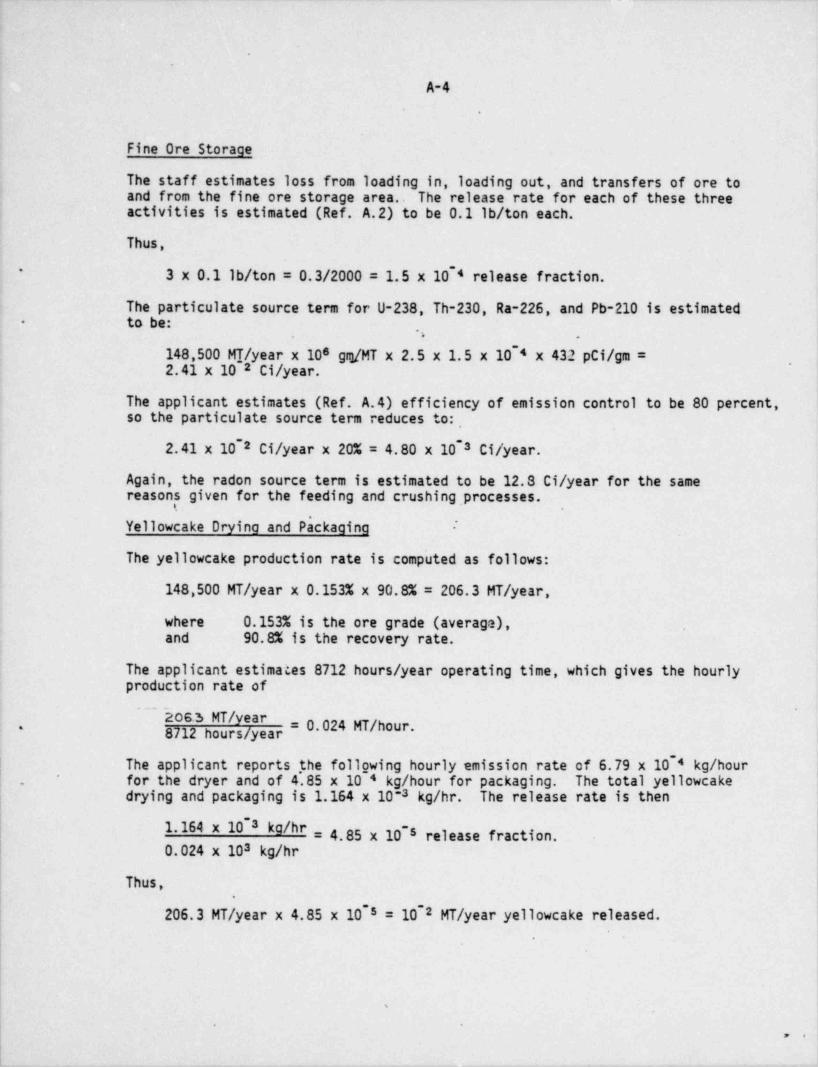
,,
A-4
Fine Ore Storage
The staff estimates loss from loading in, loading out, and transfers of ore toand from the fine ore storage area. The release rate for each of these threeactivities is estimated (Ref. A.2) to be 0.1 lb/ ton each.
Thus,-* 3 x 0.1 lb/ ton = 0.3/2000 = 1.5 x 10 4 release fraction.
The particulate source term for U-238, Th-230, Ra-226, and Pb-210 is estimatedto be:
,,.
-
-
148,500 MT/ year x 10s grg/MT x 2.5 x 1.5 x 10 4 x 432 pCi/gm =2.41 x 10 2 Ci/ year.
The applicant estimates (Ref. A.4) efficiency of emission control to be 80 percent,so the particulate source term reduces to:
- -
2.41 x 10 2 Ci/ year x 20% = 4.80 x 10 3 Ci/ year.
Again, the radon source term is estimated to be 12.8 Ci/ year for the samereasons given for the feeding and crushing, processes.
Yellowcake Drying and Packaging ~
The yellowcake production rate is computed as follows:
148,500 MT/ year x 0.153% x 90.8% = 206.3 MT/ year,
where 0.153% is the ore grade (average),and 90.8% is the recovery rate.
The applicant estimates 8712 hours / year operating time, which gives the hourlyproduction rate of
~ ~~ hos.i MT/ year= 0.024 MT/ hour.* 8712 hours / year
~
The applicant reports ,the follgwing hourly emission rate of 6.79 x 10 4 kg/ hour ,
for the dryer and of 4.85 x 10 4 kg/ hour for packaging. The total yellowcake |.
drying and packaging is 1.164 x 10⁻³ kg/hr. The release rate is then-
1.164 x 10 3 kg/hr = 4.85 x 10 s release fraction.-
0.024 x 10³ kg/hr
Thus,~
206.3 MT/ year x 4.85 x 10 5 = 102 MT/ year yellowcake released.
i
t
I
!s
|-
. .,,

1
|
A-5
The U-238 particulate source term is:- ~
10 2 MT/ year x 10s gm/MT x 3.33 x 10 7 Ci/gm U-238 x 0.85 j~
x 0.79 = 2.23 x 10 8 Ci/ year,
where 0.85 is the percent of uranium in U 0s3
*
0.79 is the reported purity of yellowcake.
The Generic Environmental Impact Statement on Uranium Milling (NUREG-0706)(Ref. A.5) reports that the activity of Th-230 in yellowcake is 0.5 percent that 1-
of U-238 and that activity of Ra-226 end Pb-210 are each 0.1 percent that ofU-238. .
,,
~ -
The Th-230 source term is 2.23 x 10 8 Ci/ year x 0.5% = 1.12 x 10 5 Ci/ year.~
The Pb-210 and Ra-226 source terms are 2.23 x 10 8 Ci/ year x 0.1% =~
2.23 x 10 8 Ci/ year.'
Radon release from yellowcake operations is assumed to be negligible.
Summary,
Except for the yellowcake source terms, the U-238, U-234, Th-230, Ra-226, andPb-210 quantities are considered to be in secular equilibrium. In general,radioactive emissions which are not explicitly calculated are assumed to beequal to the next higher-up parent in the decay chain.
The MILDOS code also accounts for mechanisms such as ingrowth of radon daughters,resuspension, deposition, all of which are further explained in Appendix B.
REFERENCES FOR APPENDIX A
'A.1. Table 4.1, Section 4.*
A.2. "APCD Mining Worksheet," prepared by William Reef, Colorado Department of ,
Health, for Enviro-Test, Ltd., March 1978.
A.3. U.S. Environmental Agency, Technical Guidar' .e for Control of Industrial . |
Process Fugitive Particulate Emissions, Report EPA-45013-010, March 1977. '
A.4. Principal Parameters for Radiological Assessment. Dawn Mining CompanyUranium Mill, May 1980.
A.5. Generic Environmental Impact Statement on Uranium Milling, NUREG-0706.Unpublished.
I
_ - - _ _ _ _ _ _ * _ _ - _ _ _ _ _ __

APPENDIX B
DETAILED RADIOLOGICAL ASSESSMENT
.
9
e
%
i
f
|
\ .
> i
1
1
1
,
||
|
'
11I
|
|

B-1.
-.
Supplemental information is provided below which describes the models, data, andassumptions utilized by the staff in performing its radiological impact assess-ment of the Dawn Mining Company Uranium Project. The primary calculational toolemployed by the staff in performing this assessment is MILDOS (Ref. B.1), an NRC-modified version of the UDAD (L''anium Dispersion and Dosimetry) computer codeoriginated at Argonne National u boratory (Ref. B.2). .
B.1 ANNUAL RADI0 ACTIVE MATERIAL RELEASES'
Estimated annual activity releas, the Dawn Mining Company Uranium Projectare provided in Table 4.2. They a aased on the data and assumptions given inTable 4.1 and described elsewhere in Section 4, with the exception of *.he annualaverage dusting rate for exposed tailings sands. This dusting rate is calculatedin accordance with the following equation:
M = 3.156 x 10⁷ y)- '
s
where F, is the annual average frequency of occurrence of wind speed group s,dimensionless;
,.
R, is the dus+,ing rate for tailings' sands at the average wind speed for2wind speed group s, for particles 1 20 pm diameter, g/m -sec;
2M is the annual dust loss per unit area, g/m yr;*
3.156 x 10⁷ is the number of seconds per year; and,
0.5 is the fraction of the total dust loss constituted by particles 120 pmdiameter, dimensionless (Ref. B.1).
The values of R and F, utilized by the staff are as given in Table B.1.s
Table B.1 Parameter values for calculation of annual dusting .
rate for exposed tailings sands
! Wind Speed Avfrage Wind Dusting Rate Frequency of .
| Group, knots Speed, mph (R,), g/m -sec* Occurrence (F )**2s
1'
0-3 1.5 0 0
| 4-6 5.5 0 0.
7-10 10.0 3.92 x 10 7 0.38011~
11-16 15.5 9.68 x 10 8 0.1831417-21 21.5 5.71x10: 5 0.04671.
>21 28.0 2.08 x 10 * 0.00993-.
I *0usting rate as a function of wind speed is computed by the MILDOScode (Ref B.1).
** Wind speed frequencies obtained from annual joint frequency data presented,
| in Table B.2.!
|
' = |- , ' :| i i'
_
_- -
'== .
y 4"r- p7 . ." j1;1* gaa -
).4}%D.99^ ,M$41].y cJ,.yi . $} M.T{' .id;
.
i$ . y *q]4 .J . . Y. J..
:.f$ 0".O
',s* . N.c*
. . ,. -- -.*
-. .17.-I . .; . .' *
1 *. - . ' 3' L. '' L . ' .'
.- . ' *# -
. 28'63289 . 7
S - 5600001 . 0390000 0190000 . 0200002 2-. 53424206500002 . 5680001 . 2539764 . 9644364 0630000 . 8900007 9L
A i200004 6410003 . 5970206 . 9390487 0420007 . 0000008 . 91607691 . 0290001 . .T 9220004 . 4076009. 3600009. 9
C i.2 0 0 0 0 3. . .._
y . . d, ; " .3. Q
' 3 6 5 0600O05 . 5800003 . 9- 210004 0 . 20174I 0 0 0,td' - .4 4c A *! * 5 . 1 1 . '91 .' 21
.i s.W!.fj ; , = % . ' .1y0 3 '...
: . ' . .* T* t,.
. C*} : . **
.d ' . 1 C' i .[. .
. ..7. 4% *. . '
8598000 . 1 49l409 0800006 3200005 13400001 . 1270000600008 . 8430006 2856004 0650709 0440009 7200009
90000087
0000000 . 0310005 2690009 . 5193201 0550009 .. 00000004 0000001 . . 0000001 . 1000005 .'7
lN 0000000.. 0101004.. 9. -e
. . . _
#~ .0000 . 0O0 ..
00 . .S ;0'9'
0' 0' . 0 e 0' . 0000 . _
30002~.* .: .. tL ,. * . g
. _
. .36400' 03 . 7730007 . 642800067000'03 8600'004 . 9v.*
2300006 4170003 . 9250007 5614008 0750003 7900007 . 5. 0100001 4620003 . 0070008 3175007 . 0470002 8000009 . 3 _
. 0000001 0300001 .0000001 . 0100601 . 0 1 1 0 0 0 3. . 0.|0000000.' . 00
..~ . . .W
N.
- . ' . ' * ' ;' 000' N.30000 - 000'. 0". 000 . ,* 0000' .!!.
' . . . c _
t 2000002 . 6580009 .' 9600005 . 1749405 . ,0690005 4000004 . 0. 8000008 8860003 6990005 2042707 0950005 0700007 . 8~,. 000000 . 5600003 1080001 5563202 . 0990000 1300004 . 30.000000*.
. . . . . . . . '' 0100002.. 0 1 1 2 0 0 6. . 0100002. 2 1 0 0 0 0 3.. 5. 0000001 .
NN
6 .
W .' 00000 . pI 000- . *1 * . 0 0 0 ' . .f) 0 . 0. 'A . 0 0 0 . * * 0000 . 1,!
.' . ; . . . .07600'03800001 . 9480001 0778002 30048s1 2400006 4n600008 . 8640000 5096002 4566149 0900008 2000002 0*
0000000 . 3150001 . 2530002 5101953 0390003 . 1900000
.7
0120004. 0356107. 0210004. 3300007. 9. ' s .0100002.-,
S*t .0 0 0 0 0 0..0
.
w * . 0000t . .51 000 . *j. 0 0 '- . . - } %4 - 1 . 0i 000 . . 0000' .. 3. a
. . . 'g . .d
3800001 . 8200000 9989905 '4950424 0700007 .-
6400000.3. 7l :600008 . 8190009 . 2s(45008 0034593 . 0750002 . 5600002 .
0000000 . 6780002. 3859006 . 1180013 . 0810000 2100004 8a w. 0100003 . 0280001 .c 0000000.. 0550008.. 1439727. 4600000. 0S . . . .
i W . - 0000 000 1 " 00 11' 0001 . 00001 . 80 .4g . .
c ,503004 . 0560001 . 341 6n80 8093415 . 0990008 9600005.J.l 3000004 . 4580008 . 2408669 3001 411 0050006 . 2800001 1
o 0200002 . 8090008 . 3639003 9046943 0120003 . 8900008 . 0
r 0000000. 0 2 1 0 0 0 4. . 0555750. 0420006. 3 6 0 0 0 0 0. . 3. 0161000 . .
w .o s'
1 . 241 0 0 10001 . 00008 .~40000 . 000 .*e . .. 1 . . 1t * 2000002 . 043000F 7746802 . 3636840 0650001 . 6400000 . 2e 0000008 . 3630002 . 6239609 7161367 . 0640001 . 3700001 . 9
- r 0000000 5120009 . 1059008 . 9612415 . 0490004 . 9200002 . 0I N 0000000. 0110002.. 0171009. 0 5 6 3 1 1 8. . 0270000.. 2500008.. 0. .
.Sy S . 00000 . 000 0 . 241 8 . 0 0001 . 0000 . 2c . . . . . 1n ~ 0100001 . 0910000 . 7339002 3991 417 . 0910000 12000038100009
3a 6100007 . 6200009 . 0047003 89200 2 . 0450000 1
u i400005 . 0330006 . 2664009 . 3996942 . 0840003 1 700008 . 6q- 0000000.. 5210004.. 0260009. 2947309.. 5100006. 2. . 0640001 . .
.e 5 . 32* 7 . 0 10002 10000l . 30.0 C 0 . 000 . 00 .'- r . -
'
. . 1f 6F00003 . 2340009 9980006 . 5824300 . 0500005 . 3800001 . 4-
. 2300006 6370006 . 2470005 . 55F1360 . 0900009 9300003 . 1e 0100001 4220009 . 3810503 3923202 . 0030003 1400006 . 7v4 E 0000000. 0140006.. 1 5 5 9 1 0 3. 0 6 6 0 0 0 2. . 3600009. 30100001 . .
S . .i0000 . 000 . 000 . 2- 4 . 0t S
' . . . . . -10002. 0000 . 8
. .a . 4500004 . 5020007 .' 3t10008 . 7239809 . 0210003 . 990000e.9l . 3000004 . 7940000 . le70002 . 3251609 . 0760003 . 8800007 . 6 .
e 0200002 . 8530001 . lt60004 . h8F2004 0950005 . 9500005.J.r 0000000.. 0000002.. 0.t20004 t.503001 0 3 3 0 0 0 7.. 3. . . 2400007 .
e . . .- E .t S . 0000 000 . 000 . 1 * 02 . 0 000 . 0000 . 4
. 'p, ' . .'
n 9500004 . 9810008 . 1568000 . 536700'1 . 0390002 4400008 31 3000004 . 0310005 5766006 . 6612007 0970007 5200007 . 83 0200002 . 6440004 2540003 . 3860008 0440009 6400000 . 9J . ' 0320004.. 1451002. 0300003. 2300006.. 9S 0 0 0 0 0 0 0. . 0100002... .E
. .0000 .
. 000 . 00~
001 0'. 000 . - 0000 . 2E. - .' . . .
-
eF00005 . 7050002 5185009 . 5996506 0530008 . 4400008 . 82 c300004 . 8680003 8470000 0161001 0000000 . 2600008 . 9i100002 . 9260009 . 3012008 0239207 0260008. 1 100002 7B . 0200003 . . 0520007 . 5600001t.0 0 0 0 0 0.. 0440008.. 3061009. 1.
. . .e E 0000 . 000 . 00 . 01 0 000 . 0000l . 5l . . . . .
b . 800004 h620004 9709803 7730007 . 0240006 2500007 . 1a f600004 . 2810002 . 561F606 8429903 0720009 6000006 . 5
i000002 . 6970003 . 6F44003 . 4548802 0940003 . 1200003 . 9T E 0 1.l.0 0 0 4. 0 3 0 0 0 0 5. .' 2 0 3 5 0 0 3. .- - 000L 100001 . 9
0000000 . . . 0880007 . 4000004. 4
N.. 0000 000 1" 01 . 12 04 0
E.' ' . . .250000F . 22F0001 . s658007 24512s2 0970006 . 3400007 . 0
000000 . 3920005 . 0544005 . 9143267 0410006 4200006 . 22200004 . 61 0000A 5395003 . 6329800 . 0890007 . 4400006 . J
0 0 0 0 0 0 0. .* 6 2.l.0 0 0 3. . 0370002.. 1994006.. 0660003.. 4800002.. 9. . . . .
_E .. 0000 . 000 -
001 .-
1 . 0 0001 . 00001 . 73N. . .
_. . .. 29420005 30F47008 47142503 .50360009 63800001 . 7in800001.
600008 . 5620004 . 5033002 0338006 . 0080006 7600004 . 2.S000u000 80004 S0940206 . S0390003 . SF000008 8
_S0000000. S41S0100602. S2558004S 0 1 2 0 0 0 4. .463005. S0410006..S3500008. 7.
S3 .E .A . A . A A A A .N .
HL 0000 . L 000 L 00 . L 01 .L0 000 . L 0000 . 3C . C C . C . C . C .
4 400008 . 1390003 . 7590805 . 8099501 . 0180009 . 3200005 1
Y3F 00000 . Y93F 0000 . TS820603 . Y2004009 . 70710008 . 76500001 4Ti200004 . T3240C01 . T27 30004 . t2018201 . 90005 . T34 00008 . 7
NI 0 0 0 0 0 0 0. . I 0 1 0 0 0 0 2. . I 0. l. 2 0 0 0 4 i1541002..T06I0210004..I 1
. . 3400007 .L L L L L . L .
. I 0000l0 000 ' . 8
. 3I 01,0000.l . 1~ 000-|i . 86 ; g0 0. 1I
u .
a550550.L BA550550.L.L.),| .. 8 B. 8
..
A550550.L.T4 S. 5 0 5 5 0.L . TA550550.L A550550.L.f. . .
S150518L S150518L.a150518LTHT T
. S15051 8L. LSi5051 8L . Sl5051 8L.1122A '
1122A 1122A 1122A . A. 1122A . 1122A ..
i ** . - . . P~ * * * .j. t t' - .I
' ..s * ; . -
9 . * .
'-
_+ - I
'
_. ,' | J .!'
-
B-3-
.
2The calculated value of the annual dusting rate, M is 420 g/m yr. Annual curiereleases from the tailings piles are then given by the following relationship:
MA (1-f ) It (C) (2;5 x 1072) (B-2)S = c2where A .is the assumed beach area of the pile, m ;
f is the fraction of the dusting rate controlled by mitigating actions, .C dimensionless;
f is the fraction of the ore content of the particular nuclide presentt ,
in the tails;-.,
,
S is the annual-release for the particular beach area, Ci/yr;'
C is the assumed raw ore activity, pCi/g;
2.5 is the dust to tails activity ratio; and
-
10 12 is Ci/pCi.
Tre tailings placed in the above grade impoundment has a raw ore activity of675 pC1/gm. The future impoundment would store tailings corresponding to alower ore activity of 432 pCi/gm.
The present impoundment (47 acres) will be used until the end of 1981, when itwill be permitted to dry. When sufficient drying has been achieved, wood chipsand/or chemical stabilization will be applied until full reclamation is begun.During the drying period, chemical stabilizers and/or surficial water sprayingwill be used to reduce dusting.
The future impoundment (26 acres) will be below grade and for the most partcovered by liquid. The staff has assigned an 80 percent reduction factor ofdusting by the methods of water cover, chemical stabilization and water sprayingduring operation. Upon application of wood chip cover, the staff assumes thatthis will effectively eliminate particulate effluents from tailings.
*
Dust losses from the ore storage piles were estimated by assuming they would beabout 10 percent of those from an equivalent area of tailings beach. Calculateddust losses were reduced by 50 percent to a'ccount for dust loss control measuresrequired by the staff. -
B.2 ATMOSPHERIC TRANSPORT
The staff analysis of offsite air concentrations of radioactive materials has beenbased on five years of meteorological data collected at Spokane, Washington, overthe period 1967 through 1971 (Ref. B.3). The collected meteorological data areentered into the MILDOS code as input, in the form of a joint. frequency distribu-,
| tion by stability class, wind speed group, and direction. The joint frequencydata employed by the staff for this analysis are presented in Table B.2.
*.

- . . -
B-4.
The dispersion model employed by the MILDOS code is the basic straight-line*
Gaussian plume model (Ref. 8.1). Ground-level, sector-average concentrations arecomputed using this model and are corrected for decay and ingrowth in transit(for Rn-222 and daughters) and for depletion due to deposition losses (forparticulate material). Area sources are treated using a virtual point sourcetechnique. Resuspension into the air of particulate material initially depositedon ground surfaces is treated using a resuspension factor which depends on theage of the deposited material and its particle size (Ref. B.1). For the isotopes*
of concern here, the total air concentration including resuspension is about 1.6times the ordinary air concentration.
The assumed particle size distribution, particle density, and deposition velocities-
for each source are presented in TabTe B.3.~
-
Table B.3 Physicd1 characteristics assumed for particulate material releases
DepositionDiameter Density Velocity AMAD*Activity Source pm g/cm3 cm/sec pm
! Activity SourceCrusher dusts 1.0 2. 4 1. 0 1.55
*
Yellowcake dusts 1.0 8.9 1.0 2.98Tailings, ore pile dusts 5.0 (30%) 2.4 1.0 7.75Tailings, are pile dusts 35.0 (70%) 2.4 8.8 54.2Ingrown Rn daughters 0 1.0 0.3 0.3
* Aerodynamic equivalent diameter, used in calculating inhalation doses (Ref. 8.1).
B.3 CONCENTRATIONS IN ENVIRONMENTAL MEDIA
Information provided below describes the methods and data used by the staff todetermine the concentrations of radioactive materials in the environmental media
-
| of concern in the vicinity of the site. These include concentrations in the air(for inhalation and direct external exposure), on the ground (for direct external!
| exposure), and in mear and vegetables (for ingestion exposure). Concentration'
values are computed explicitly by the MILDOS code for U-238, Th-230. Ra-226,Rn-222 (air only), and Pb-210. Concentrations of Th-234, Pa-234, and U-234, areassumed to be equal to that of U-238. Concentrations of B1-210 and Po-210 areassumed to be equal to that of Pb-210.
B.3.1 Air Concentrations
Ordinary, direct air concentrations are computed by the MILD 05 code for eachreceptor location, from each activity source, by particle size -(for particulates).Direct air concentrations computed by MILDOS include depletion by deposition
_
.p- m e

._
|1
B-5.
.
(particulates) or the effects of ingrowth and decay in transit (radon anddaughters). In order to compute inhalation doses, the total air concentrationof each isotope at each location, as a function of particle size, is computedas the sum of the direct air concentration and the resuspended air concentration:
= Caipd + Caipr(t), (B-3)C,gp(t)
where C,$p(t) is the total air concentration of isotope 1, particle size p,8at time t, pCi/m ; .
C is the direct air concentration of isotope 1, particle size p,aipd 8for the time constant, pCi/m ; and
aipr(t) is the resuspended air concentration of isotope i, particleC8size p, at time t, pCi/m .
The resuspended air concentration is computed using a time-dependent resuspensionfactor, R (t), defined by
p
-A t (for t < 1.82 yr) (B-4a)~
(1/V )10 5 eR (t) R=.
p p
(1/V )10 ' ('for t > 1.83 yr) (B-4b)~
R (t) =p p
where R (t) is the ratio of the resuspended air concentration to the groundp concentration, for,a ground concentration of age t years, of
particle size p, m 1;
V is the deposition velocity of particle size p, cm/sec;p
A is the assumed decay constant of the resuspension factorR
(equivalent to a 50-day half-life), 5.06 yr;.
-
10 s is the initial value of the resuspension factor (for particleswith a deposition ve1ocity of 1 cm/sec), m 1;
~
10 ' is the terminal value of the resuspension factor (for particleswith a deposition velocity of I cm/sec), m 1; ar.d
1.82 is the time required to reach the terminal resuspension factor,years.
The basic formulation of the above expression for the resuspension factor, theinitial and final values, and the assigned decay constant derive from experimentalobservations (Rev. B.3). The inverse relationship to deposition velocity eliminatesmass balance problems involving resuspension of more than 100 percent of theinitial ground deposition for the 35 pm particle size (see Table B.3). Based onthis formulation, the resuspended air concentration is given by:
,
- _ _ _ - _ _ _ - _ . - _ _ - - _ - - _ _ . _ . _ _ - _ - - - _ . -

B-6
^i + A )(t - a)]~*R~
10 5 (B-5)C,9pp(t) = 0.01 Cai d (A * + A )'''
t g.
exp[-k '(t - a)]- exp (-A *t) ~j g_
+ 10 46(t) (3.156 x 10⁷)g,i .
,
where a is equal to (t - 1.82) if t < l.82 and is equal to zero otherwise,years;.
6(t) is zero if t < l.82 an'd is unity otherwise', dimensionless;
A* is the effecti~ve decay constant for isotope i on soil, year" ;g
,
0.01 is the deposition velocity for the particle size for which theinitial resuspension factor value is 10 5 per meter, m/sec;
3.156 x 10⁷ is sec/ year..
Total air concentrations are computed using equations B-5 and B-3 for allparticulate effluents. . Radon daughters wh.ich grow in from released radon arenot depleted due to deposition losses and are therefore not assumed to resuspend.
B.3.2 Gro and Concentrations
Radionuclide ground concentrations are computed from the calculated airborneparticulate concentrations arising directly from onsite sources (not includingair concentrations resulting from resuspension). Resuspended particulate con-centrations are not considered for evaluating ground concentrations. The directdeposition rate of radionuclide i is calculated, using the following relationship:
i
Ddi = C (B-6a)adip p,,
' P
. is the direct air concentration of radionuclide i,where Cadip 3particle size p, pCi/m ;-
| 2|
D is the resulting direct deposition rate of radionuclide i, pCi/m -sec;diI
| V is the deposition velocity of particle size p, m/sec (see Ref. B.4).. p
The concentration of radionuclide i on a ground surface due to constant depositionat the rate D ver time interval t is obtained fromdi
1 - exp -(Aj + A,)t -
(B-6b)g (t) = Ddi A +AC j ,
i e. .
. .

. - _ _ _ _ _ - _ _ _
.
B-7.
where C9j(t) is the ground surface concentration of radionuclide i at time t,2pCi/m ;
t is the time interval over which deposition has occurred, sec;
A, is the assumed rate constant for environmental loss, sec~1;
A is the radioactive decay constant for radionuclide 1, sec"1 .j
The environmental loss constant, A,, corresponds to an assumed half-time for loss ,
of environmental availability of 50 years, (Ref. B.3). This parameter accounts fordownward migration in soil and loss of availability due to chemical binding. It
is assumed to apply to all radionuclides deposited on the ground. ~
Ground concentrations are explicitly computed only for uranium-238, thorium-230,radium-226, and lead-210. For all other radionuclides, the ground concentrationis assumed equal to that of the first parent radionuclide for which the groundconcentration is explicitly calculated. For lead-210, ingrowth from depositedradium-226 can be significant. The concentration of lead-210 on the ground dueto radium-226 deposition is calculated by the staff, using the standard Batemanformulation and assuming that radium-226 decays directly to lead-210. If i = 6for ra'dium-226 and i = 12 for lead-210 (Ref. B.1), the following equation isobtained: -
.
I ~ **PC-A*2 ) + exp(-A*6 ) - exp(-A*2 t)'A 0 t tjp d6Cg12(Pb- Ra) = (B-7)g,
g,12g,
g ,12,_
6 6. .
where Cg12(Pb- Ra) is the incremental lead-210 ground concentration resulting2from radium-226 deposition, pCi/m ;
A* is the effective rate constant for loss by radioactive decayand migration of a ground-deposited radionuclide and is equalto A * A , sec ( '
n e
~
B.3.3 Vegetation Conc ntrations .
.
Vegetation concentrations are derived from ground concentrations and totaldeposition rates. Total deposition rates are given by the following summation:,
09= C,jp p,V (B-8a)P
where D is the total deposition rate, including deposition of resuspended activity,j2of radionuclide i, pCi/m .sec.
,
;
-
,
;
|
B-8 '
.
|Concentrations of released particulate materials can be environmentally trans- |
ferred to the edible portions of vegetables, or to hay or pasture grass consumed I
by animals, by two mechanisms--direct foliar retention and root uptake. Fivecategories of vegetation are treated by the staff. They are edible above groundvegetables, potatoes, other edible below ground vegetables, pasture grass, andhay. Vegetation concentrations are computed using the following equation:
. . .
1 - exp(-A,t )yCyg=DEE + C ,(Byj/P) (B-8b)j py g ,
- .. .
where B is the soil-to plant transfer factor for isotope i, vegetation type v,yjdimensionless;
C is the resulting concentration of isotope i, particle size p, inygp vegetation v, pCi/kg;
E is the fraction of the foliar deposition reaching edible portions ofyvegetation v, dimensionless; *
F is the fraction of the total deposition retained on plant surfaces,r 0.2, dimensionless;
P is the assumed areal soil density for surface mixing, 240 kg/m ;2
t is the assumed duration of exposure while growing for vegetation v,ysec;
Y, is the assumed yield density of vegetation v, kg/m ;2
A,is the decay constant accounting for_ weathering losses (equivalentto a 14-day half-life), 5.73 x 10 7 per second.
| The value of E is assumed to be 1.0 for all above ground vegetation, and 0.1yfor all below grcund vegetables (Ref. B.7). The value of t is taken to be 60.
,
y
days, except for pasture grass, where a value of 30 days is assumed. The yielddensity, Y,, is taken to be 2.0 kg/m except for pasture grass, where a value2
' of 0.75 kg/m2 is applied. Values of the soil to plant transfer coefficients,i'
Byg, are provided in Table B.4.
B.3.4. Meat and Milk Concentrations
| Radioactive materials can be deposited on grasses, bay, or silage which is eatenby meat animals, which are in turn eaten by man. It has been assumed that meatanimals obtain their entire feed requirement by grazing eight months per year,and by eating nonlocally grown stored feed for approximately 10 weeks. The
j equation used to estimate meat concentrations is:|
.
.
__ _m.______ _ _ - - . _ _ _ _ __ _ _
d+9+\ [v'4$.im.e. .v <u 1,.
TEST TARGET (MT-3),
'
' m Bugl.0y || IlE
'
: 1.1 ['" lM!
-
|Us'-
1.25 IA i.6
4 6" >
i
! b
*k,>#'
/. 'AS
, <.

*''kh+> k\xNNkh'k IMAGE EVALUATION NNNN
TEST TARGET (MT-3)
.
I
1.0 ' dea 834 .
E!EE 1
1.1 L'" lE ;
M'~
I.25 || IA 1.6|| _
!
*-- - 6" =
'
44 4 +A$1f'W 45;gf4*
// _
4<S4.

I
l
B-9.
Table B.4 Environmental transfer coefficients -
Material U Th Ra Pb
Plant / Soil (Byg)Edible above ground 2.5x10[3 4.2x10[3 1.4x10;2 4.0x10[3Potatoes 2.5 x 10 8 4.2 x 10 3 3.0 x 10 3 4.0 x 10 3 '
Other below ground 2.5x10[3 4.2x10[3 1.4x10}2 4.0x10[3Pasture grass 2.5 x 10_3 4.2 x 10_3 1.8 x 10_2 2.8 x 10_23
Stored feed (hay) 2.5 x 10 8 4.2 x 10 8.2 x 10 2 3.6 x 10 3'
-.
Beef / Feed (Fg) _
7.1 x 10 4pCi/kg per pCi/ day 3.4'x 10 4 2.0 x 10 4 5.1 x 10- ~
Source: U.S. Nuclear Regulatory Commission, " Calculational Models forEstimating Radiation Doses to Man from Airborne Radioactive MaterialsResulting from Uranium Operations," Task RH 802-4, May 1979.
Cbi = Q Fbi (0.67 C + 0.20 Chi) (B-9a)pgj
where C is the concentration of isotope i in pasture grass, pCi/kg;pgg
C is the concentration of isotope i in hay (or other stored feed),hi pCi/kg;
C is the resulting concentration of isotope i in imeat, pCi/kg;bi
F is the feed to meat transfer factor for isotope i, pCi/kg per pCi/ daybi (see Table B.4);
Q is the assumed feed ingestion rate, 50 kg/ day;
0.67 is the fraction of the total annual feed requirement assumed to besatisfied by pasture grass; and
0.20 is the fraction of the total 2nnual feed requirement assumed to be .
satisfied by locally grown stored feed (hay).
The above grazing assumptions are also reflected in the following equation formilk concentrations:
Cg=QFg (0.67 Cpgg + 0.20 Cg) (B-9b)
where C is the average concentration of iostope'i in milk, pCi/2; andg
Fmi is the feed to milk activity transfer factor for isotope i, pCi/2per pCi/ day ingested (see Table B.4).
,
i
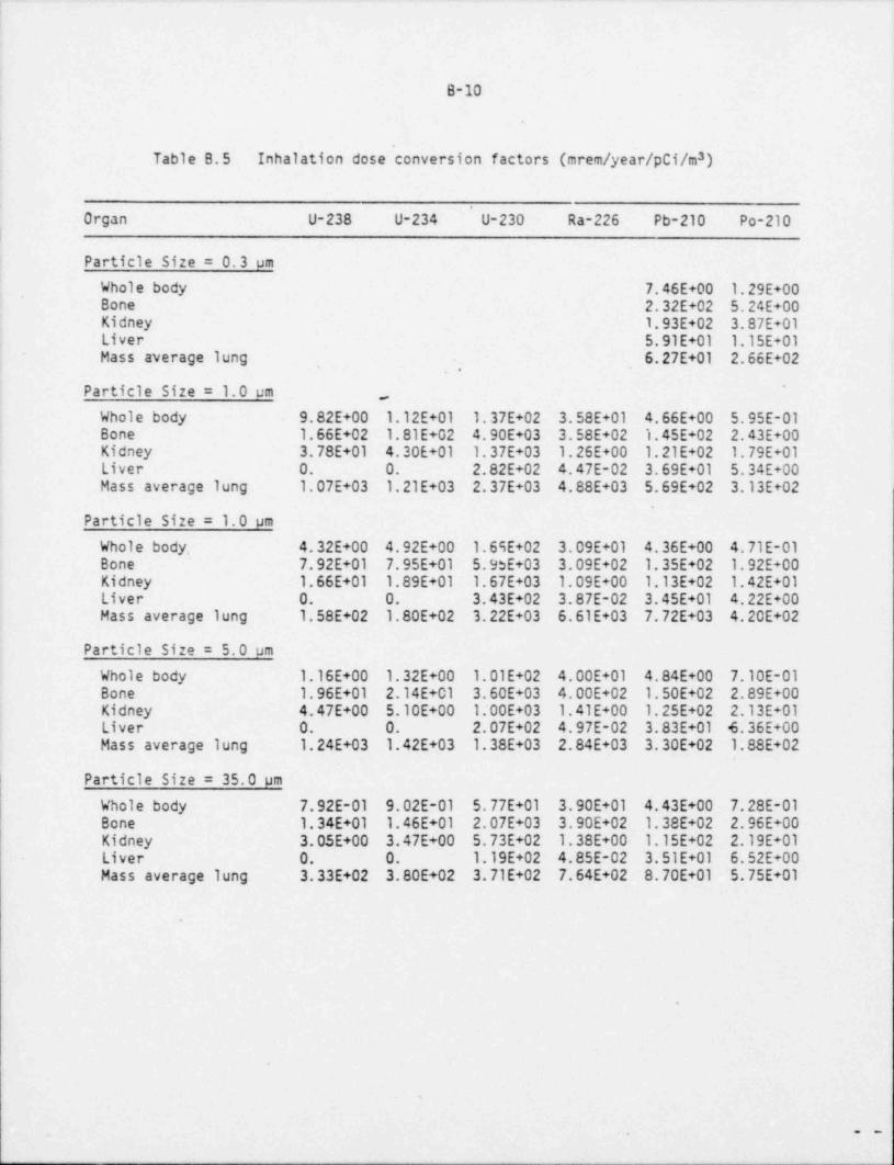
B-10
Table 8.5 Inhalation dose conversion factors (mrem / year /pCi/m )3
'
Organ U-238 U-234 U-230 Ra-226 Pb-210 Po-210|
Particle Size = 0.3 umWhole body 7.46E+00 1.29E+00Bone 2.32E+02 5.24E+00Kidney 1.93E+02 3.87E+01Liver 5.91E+01 1.15E+01
- Mass average lung 6.27E+01 2.66E+02,
Particle Size = 1.0 um '
,
Whole body 9.82E+00 1.12E+01 1.37E+02 3.58E+01 4.66E+00 5.95E-01Bone 1.66E+02 1.81E+02 4.90E+03 3.58E+02 1.45E+02 2.43E+00Kidney 3.78E+01 4.30E+01 1.37E+03 1.26E+00 1.21E+02 1.79E+01Liver 0. O. 2.82E+02 4.47E-02 3.69E+01 5.34E+00Mass average lung 1.07E+03 1.21E+03 2.37E+03 4.88E+03 5.69E+02 3.13E+02
.
Particle Size = 1.0 um
Whole body,~7.92E+01 7.95E+01 5.9dE+03 3.09E+02 1.35E+02 1.92E+004.32E+00 4.92E+00 1.69E+02 3.09E+01 4.36E+00 4.71E-01
BoneKidney 1.66E+01 1.89E+01 1.67E+03 1.09E+00 1.13E+02 1.42E+01Liver 0. O. 3.43E+02 3.87E-02 3.45E+01 4.22E+00Mass average lung 1.58E+02 1.80E+02 3.22E+03 6.61E+03 7.72E+03 4.20E+02
Particle Size = 5.0 umWhole body 1.16E+00 1.32E+00 1.01E+02 4.00E+01 4.84E+00 7.10E-01Bone 1.96E+01 2.14E+01 3.60E+03 4.00E+02 1.50E+02 2.89E+00Kidney 4.47E+00 5.10E+00 1.' 00 E+03 1.41E+00 1.25E+02 2.13E+01Liver 0. O. 2.07E+02 4.97E-02 3.83E+01 4.36E+00Mass average lung 1.24E+03 1.42E+03 1.38E+03 2.84E+03 3.30E+02 1.88E+02
Particle Size = 35.0 pm
Whole body 7.92E-01 9.02E-01 5.77E+01 3.90E+01- 4.43E+00 7.28E-01Bone 1.34E+01 1.46E+01 2.07E+03 3.90E+02 1.38E+02 2.96E+00Kidney 3.05E+00 3.47E+00 5.73E+02 1. 38E+00 1.15E+02 2.19E+01Liver 0. O. 1.19E+02 4. 85 E-02 3.51E+01 6.52E+00Mass average lung 3.33E+02 3.80E+02 3.71E+02 7.64E+02 8.70E+01 5.75E+01
s
,e m

B-11
B.4 DOSES TO INDIVIDUALS
Doses to individuals have been calculated for inhalation, external exposureto air and ground concentrations, and ingestion of vegetables, meat, and milk.Internal doses are calculated by the staff, using dose conversion factors thatyield the 50-year dose commitment, that is, the entire dose insult receivedover a period of 50 years following either inhalation or ingestion. Annualdoses given are the 50-year dose commitments resulting from a one-year exposure -
period. The one-year exposure period was taken to be the final year of milloperation, when environmental concentrations resulting from plant operationsare expected to be near their highest level. _
B.4.1 Inhalation doses
Inb41ation doses have been computed using air concentrations obtained byE . B .! (resuspended air concentrations are included) for particulate materials4and the dose conversion factors presented in Table B.5 (refs. I and 6).
Doses to the bronchial epithelium from Rn-222 and short-lived daughters werecomputed based on the assumption of indoor exposure at 100% occupancy. Thedose conversion factor for bronchial epithelium exposure from Rn-222 derives asfollows:
3 -61) 1 pCi/m Rn-222 = 5 x 10 Working Level (WL).*
2) Continuous exposure to 1 WL = 25 cumulative working level months (WLM)per year.
3) 1 WLM = 5000 mrem (Ref. B.8).
Therefore:
3 -6| (1 pCi/m Rn-222) x (5 x 10 ,3) x (25 Ehf)x(5000"'*")=0.625 mremp g
|
| and the Rn-222 brgnchial epithelium dose conversion factor is taken to be 0.625| mrem /yr per pCi/mi
B.4.2 External Doses
! External doses from air and ground concentrations are computed using the dose| conversion factors provided in Table B.6 (Ref. B.1). Doses are computed based on| 100 percent occupancy at the particular location. Indoor exposure is assumed to
occur 14 hrs / day at a dose rate of 70% of the outdoor dose rate.
l|
|
|
I
|
i

B-12
.
Table B.6 Dose conversion factors for external exposure
Dese factors for doses from air Dose factors for doses from groun43concentrations, mres/yr per pCi/m concentrations, mrem /yr per pCi/m'
Isotope Skin Whole body Isotope Skin Whole Body.
U-238 1.05 E-05 1.57 E-06 U-238 2.13 E-06 3.17 E-07Th-234 6.63 E-05 5.24 E-05 Th-234 2.10 E-06 1.66 E-06
. Pa(m)-234 8.57 E-05 6.64 E-05 Pa(m)-234 1.60 E-06 1.24 E-06U-234 1.36 E-05 2.49 E-06 U-234 2.60 E-06 4.78 E-07Th-230 1.29 E-09 3.59 E-06 Th-230 2.20 E-06 6.12 E-07Ra-226 6.00 E-05 4.90 E-05 Ra-226 1.16 E-06 9.47 E-07Rn-222 3.46 E-10 2.83 E-06 Rn-222 6.15 E-08 5.03 E-08Po-218 8.18 E-07 6.34 E-07 Po-?l8 1.42 E-08 1.10 E-08Pb-214 2.06 E-03 1.67 E-03 Pb-214 3.89 E-05 3.16 E-05Bi-214 1.36 E-02 1.16 E-02 Bi-214 2.18 E-04 1.85 E-04Po-214 9.89 E-07 7.66 E-07 Po-214 1.72 E-08 1.33 E-08Pb-210 4.17 E-05 1.43 E-05 Pb-210 6.65 E-06 2.27 E-06
*0ne WL concentration is defined as any combination of short-lived #*di **'I"* d***Y5products on Rn-222 in one liter of air that will release 1.3 x 10 MeV of alphaparticle energy during radioactive decay to Pb-210.
B.4.3 Ingestion Doses
Ingestion doses are computed for vegetables and meat (beef and lamb) on the basisof concentrations obtained using Equations B-8 and B-9, ingestion rates given inTable B.7, and dose conversion factors given in Table B.8 (Refs. B.1, B.9). Vegetableingestion doses were computed assuming an average 50 percent activity reductiondue to food preparation (Ref. B.4). Ingestion doses to children and teenagers werecomputed but found to be equivalent to or less than doses to adults.
.
.
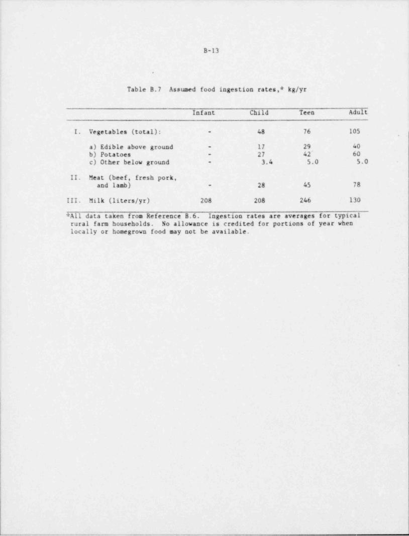
B-13
.
Table B.7 Assumed food ingestion rates,* kg/yr
Infant Child Teen Adult
48 76 105I. Vegetables (total): -,
a) Edible above ground - 17 29 4027 42^ 60b) Potatoes -
3.4 5.0 5.0 -c) Other below ground -
II. Meat (beef, fresh pork,28 45 78and lamb) -
III. Milk (liters /yr) 208 208 246 130
*All data taken from Reference B.6. Ingestion rates are averages for typicalrural farm households. No allowance is credited for portions of year whenlocally or homegrown food may not be available.
ii
b
e
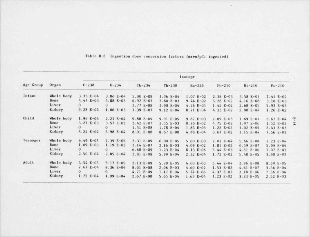
. _ - _ _ _ - _ . _ _ _ - -
. ..
: Table B.8 Ingestion dose conversion factors (ares /pCi ingested)
f
Isotope
Age Group Organ U-238 U-234 Th-234 Th-230 Ha-226 Pb-210 Bi-210 Po-210
- Infant Whole body 3.33 E-04 3.80 E-04 2.00 E-08 1.06 E-04 1.07 E-02 2.38 E-03 3.58 E-07 7.41 E-04Bone 4.47 E-03 4,88 E-03 6.92 E-07 3.80 E-03 9.44 E-02 5.28 E-02 4.16 E-06 3.10 E-03Liver 0 0 3.77 E-08 1.90 E-04 4.76 E-05 1.42 E-02 2.68 E-05 5.93 E-03Kidney 9.28 E-04 1.06 E-03 1.39 E-07 9.12 E-04 8.71 E-04 4.33 E-02 2.08 E-04 1.26 E-02
Child Whole body 1.94 E-04 2.21 E-04 9.88 E-09 9.91 E-05 9.87 E-03 2.09 E-03 1.69 E-07 3.67 E-04 ?Bone 3.27 E-03 3.57 E-03 3.42 E-07 3.55 E-03 8.76 E-02 4.75 E-02 1.97 E-06 1.52 E-03 5Liver 0 0 1.51 E-08 1.78 E-04 1.84 E-05 1.22 E-02 1.02 E-05 2.43 E-03Kidney 5.24 E-04 5.98 E-04 8.01 E-08 8.67 E-08 4.88 E-04 3.67 E-02 1.15 E-04 7.56 E-03
Teenager Whole body 6.49 E-05 7.39 E-05 3.31 E-09 6.00 E-05 5.00 E-03 7.01 E-04 5.66 E-08 1.23 E-04Bone 1.09 E-03 1.19 E-03 1.14 E-07 2.16 E-03 4.09 E-02 1.81 E-02 6.59 E-07 5.09 E-04Liver 0 0 6.68 E-09 1.23 E-04 8.13 E-06 5.44 E-03 4.51 E-06 1.07 E-03Kidney 2.50 E-04 2.85 E-04 3.81 E-08 5.99 E-04 2.32 E-04 1.72 E-02 5.48 E-05 3.60 E-03
Adult Whole body 4.54 E-05 5.17 E-05 2.13 E-09 5.70 E-05 4.60 E-03 5.44 E-04 3.96 E-08 8.59 E-05Bone 7.67 E-04 8.36 E-04 8.01 E-08 2.06 E-03 4.60 E-02 1.53 E-02 4.61 E-07 3.56 E-04Liver 0 0 4.71 E-09 1.17 E-04 5.74 E-06 4.37 E-03 3.18 E-06 7.56 E-04Kidney 1.75 E-04 1.99 E-04 2.67 E-08 5.65 E-04 1.63 E-04 1.23 E-02 3.83 E-05 2.52 E-03
.

B-15
References for Appendix B
B.1. U.S. N'uclear Regulatory Commission, "Calculat .onal Models for EstimatingRadiation Doses to Man from Airborne Radioact.:e Materials Resulting fromUranium Milling Operations, Task RH 802-4, May 1979.
B.2. M. Momeni, et al., " Uranium Dispersion and Dosimetry (UDAD) Code," ArgonneNational Laboratory Report, ANL/ES-72, NUREG/CR-0553, May 1979. .
B.3. " Wind Distribution of Pasquill Stability Classes - Spokane, Washington,1967-1971," National Climatic Center, Asheville, North Carolina.
_
B.4. " Draft Generic Environmental Impact Statement on Uranium Milling," U.S.Nuclear Regulatory Commission, NUREG-0511. April 1979.
B.S. D. C. Kocher, " Nuclear Decay Data for Radionuclides Occurring in RoutineReleases from Nuclear Fuel Cycle Facilities," Report ORNL/NUREG/TM-102,Oak Ridge National Laboratory, August 1977.
B.6. J. F. Fletcher and W. L. Dotson (compilers), " HERMES - A Digital ComputerCode for Estimating Regional Radiological Effects from the Nuclear PowerIndustry," Hanford Engineering Development Laboratory, HEDL-TME-71-168,December 1971.
B.7. D. R. Kalkwarf, " Solubility Classification of Airborne Products fromUranium Ores and Tailings Piles," Report NUREG/CR-0530; PNL-2830, PacificNorthwest Laboratory, January 1979.
B.8. National Academy of Sciences - National Research Council, "The Effects onPopulations of Exposure to Low Levels of Ionizing Radiation," Report on theAdvisory Committee on Biological Effects of Ionizing Radiation (BEIR),U.S. Government Printing Office, 1972.
B.9. G. R. Hoenes and J. K. Soldat, " Age-Specific Radiation Dose ConversionFactors for a One-Year Chronic Intake," Battelle Pacific NorthwestLaboratories, U.S. Nuclear Regulatory Commission Report NUREG-0172,November 1977.
.
9
- - - . - . - .-. .- -
. .
4
.
.
.
.
. .
.
.
..
.
-
APPENDIX C
..
Stability Computations
..*.; *
.
.
O
.
.
e m

C-1' *
APPENDIX C
Slope Stability Analysis .
DAWN MINING COMPANY
This analysis utilized the program STABL2. A total of 10 potential
failure surfaces were generated from each of three initiation points..
The three initiation points included: 1) the toe of the proposed pit,
2) the crest of the proposed dike, and 3) a point midway between these ,
two points on the pit, slope. The left termination point was taken as the
crest of the proposed facility and the right termination point as a point
on the existing tailing surface. Minimum elevation of surface development
was taken as 75', a distance of 25' below the bottom of the proposed pit.
Limits forLength of segments defining the surfaces was taken as 15'.
surface initiation angles were randomly chosen by the computer.
Factors of Safety (for the ten most critical of the trial failure
surfacesexamined)
1. 1.950 6. 2.207
2. 2.016 7. 2.211
3. 2.102 8. 2.215
4. 2.166 9. 2.217 ,
5. 2.168 10. 2.245*.
* Note: Initiation point coordinates: x = 200.5, y = 133.5 (located -
on pit slope) F.S. = 2.25.
Initiation point coordinates for the remaining 9 failure surfaces:x = 100.0, y = 100.0 (located at the toe of the proposed pit)
,
F.S.,yg = 2.14. -.
-- - ,. - - u,- , , - - - -- >w- , -, , ,,- ,- w

- w s,
1* u u %sR ''
6 @ ] . d o\s co d
J o M '" @d o 4 '.qgGSR R _MStu o,
NU G
a ! 'i v> eu % w e< ( Q=.i.
]$g . i c;A .,.
lj v) o s. d=34 04WVp, ~~ .
Q
:> -tO
," i.
* g-
-g-
4' O ., -n .
%
'kao
NN ic
4
-!'b'
e
-= .*
i y,-'
._
%a .-
f '$ c$J,
'
: i s. .y.
.
o O-4 h
.
. x.
,.
' O k.
-k-
. g.
w, M; .
k'
Si o
'R gA-
b.
> .
9.o
... ..
k k, k*
.. .
_
b h
- ..
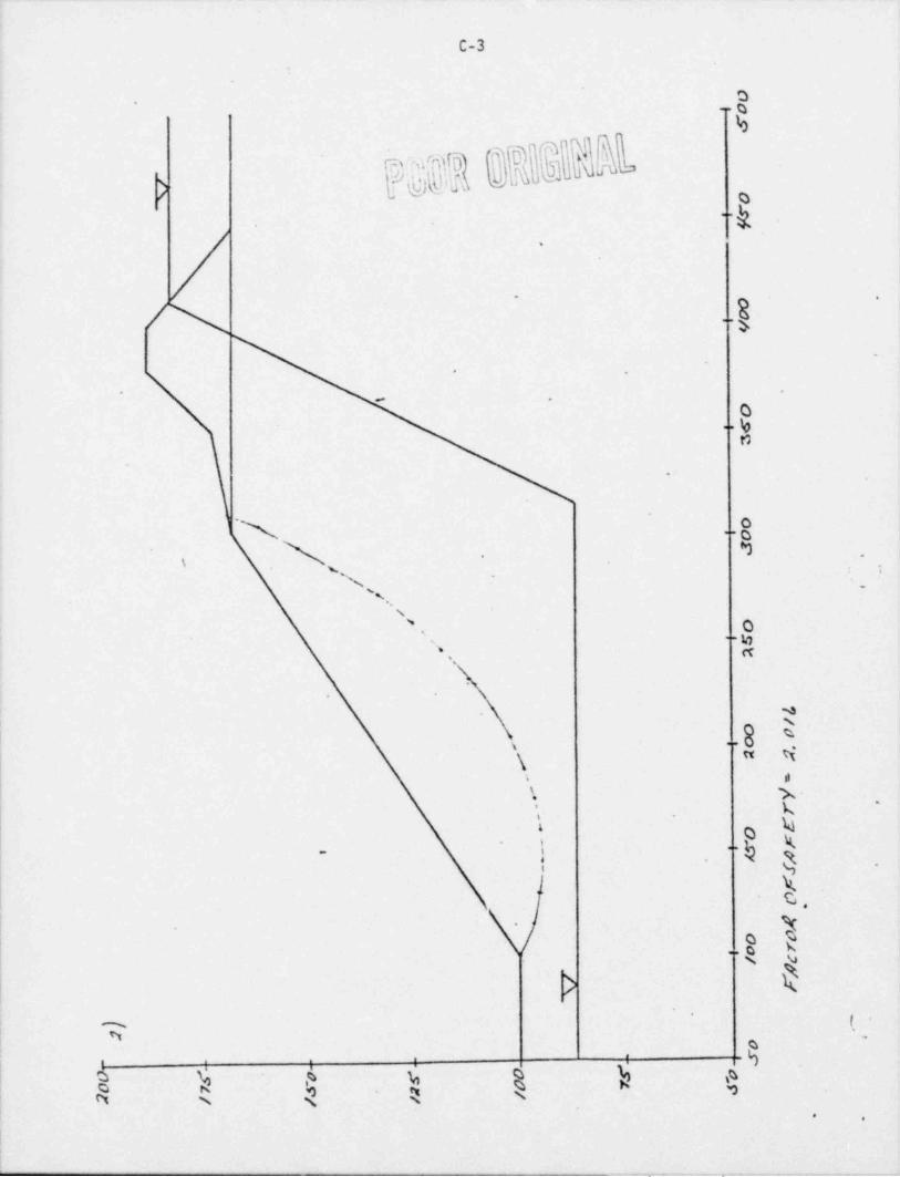
C-3,
O
ED
hi$$$0$000NN'-k,
,
. -
/\ .. f
0 e
4
W e
0y..
n
..
.- O
N .
1 A .
.
s,
N Os g..
' n'.
*
N
4i
..
a wks; x-
.
Li .
4O g.,
!. ~ g4 .
..-
h.
\- et..'
>'
'; y .
.
!-@:.
, . .
6 h AR $, $ N 4
n n R-
.
:I
- ' - - - - . . _ _ 'M% _ _

5 A
Id
...
$..
.
e
( *
"~h.
.
.
Q..h
t)
x. .e.
N .._ .'
~ ~ . . b.*
' '
.
\,
x"'
.a..
. M'
,. .
't+*
i gs. si s-
1 y| \ u!
. %i
t%,
.
k- , xq.-
. . .
g.
] %-
.,
/
.o x< g u.
*. N
-
o'
, D',
k, k, 4'N k h $
,
ts. .
W 9
- y , -- , , ,-,m ..,i-y . - - , - _ , . - , - _ .m , . , , - - - , . - - - - + , . - . , , - -

E w
C-5 .
J'
d .
,
*..
;
.f '
*,e_
.
O
e
Q.s.
.
N .. .
'
..
s .
g
's% * g
* .
4g
N-s.
'.
*
N.
oI. .a 4.
D 4, s
-i ,
| XK-
.. Ni
i k .
E| i,
g< <
4
> / o.
/ k I..
N <
k''
g ,
a, , ; :
l 4 ( ( i! k:.
i
4. .
- + w --~e - - , , , , - _ _ , .,. _,,.g. ,, ,_,,.,. , _ . , , , _ _ , _ , . , . , .

P002 GREMal"~ " ' '
'- o.
.
e e
a MP
.
0-
-.
e
s-
N haP
x\
.,
\ . .
A. - o,
| '\ $"
: ;.
('
; -
.-.
-%
*i'
, ..
*-. %
",,
' %'. o 4
a %--
n ts-
.
H.
.
k. Og ..,,
. s
\.\xt 0
| $~~
k-
l ,9 <
$'
:...
|- i. .
-
..
't
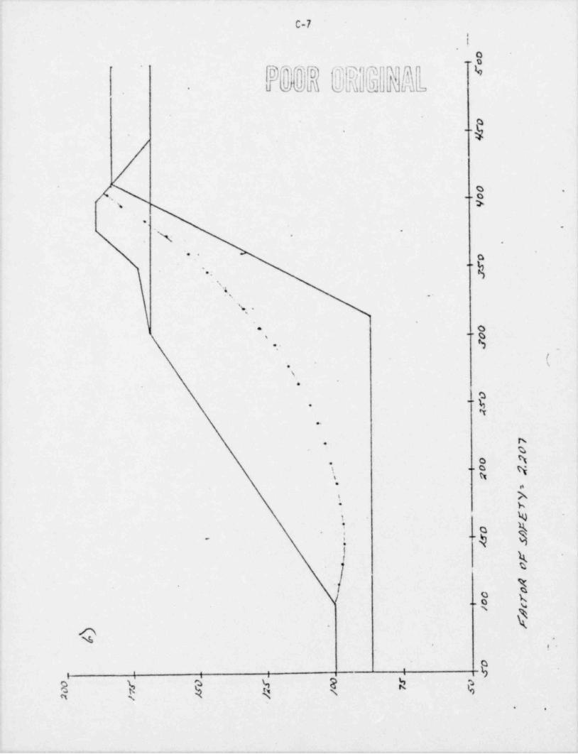
y
C-7.
'
o..g
4D"'"]D'* Ff T T ObbA .k frdo- . c o Ju
~
. ..y
C .
.o.
.'\. >.
.- .
,
.
-. .
""'
.:
s,s .-
%, .,
,..O*
#.
t.
*\
\
e
- t,-.
N.* %
O h.
\ .o y.
s tt* n
I.
h-
1 % ~
$
''4.
I g '
t- 8 x
u,\k-
p% .
. ..
; ; I',
$ ) 4 ) R h 4. .
- 7 - - - - -, .mr r3 ,,- - *- c . 7 , e-,-- - - , - - - -

a L
C-8 1
- %-
.
pg@@ @ESNb -
h- ..
.
..g-
- .
,
..
..
O"
' ' ' - . . ,,
_ . - -..
N..sg .-
N. o''. ..
1s:
\
N
.
k-.
esk ei- -
S,
D,
-
%~
g..
4! ke
..-
- %-
%*
*
>
,
/. '
.R ns
u
-
'
,
N kR. .
4

t . - Q s a
1
- C-9
O-
'
. ,
. ..yi
/, . .
'
./ -$-
.
.
e
9 *
.
*
-. 8
~ _ : .
(s
-...', '~-
,. . s
' .
m
S . t,. ..
w. .: .
-!
4 ..'
s
9
. . ..a b '
W! n| k Ni u,
!{ -
- =.. ..
,_
-.
/ H4
*s
S|
.a g-. .
s -
xv
*
ig| ,$:
k-
. .
l
. _ . , . _. _ .-. . _ _ . . . . _ . , . _ . , , , _,_.-~ , , . , . _ . _ , . , . , . _ , , , . _ _ - , . . , , . _ . . . _ . . . .._,..__..._ ...-_...-,. ,
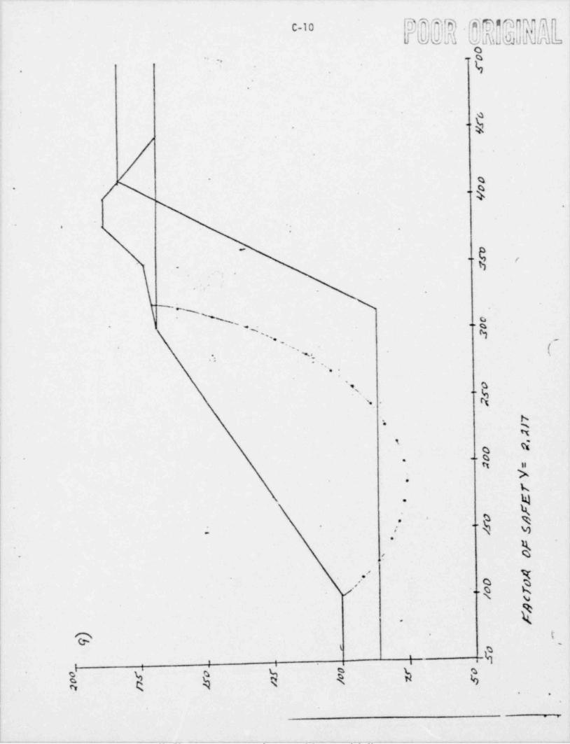
8.---
O.. g-- .,
'' * k. ,
.
4*'
' . )' %
f ..
.
$ 1
*
e*
....
o-
, .g.q' . , h-
(. . . ,- -
-,. * ~.,:
*
' s. s G..
,N .
b** w
Mi -
D-%-.tt H
W.
kN-
. As s-.
''k v3*
/
* h. ,
.;
,/ QI
%/ ..\ 9Nk-
9 t-
-
! t 2I k
. -' i
.. .
.
.
W F
- - - - - - - . . - - _ _ . . __ _ _ _ . _ ._. . _ . . _ _ __ . _ . _ _ . _
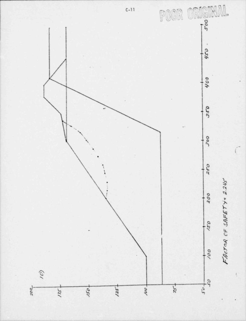
u-
.
._z
.
em
..
O.
,
, -
.O
ga
' %,, **
N.. o
\ qi "
; .-
(_'
-.
\an
\ n
'. hi nf No
O y--
4 %b
k,M .
k..*
N k.
G .
7bo-
-R.
e i. '.
'
9-
( g 4 j zh; ,a
,
. .,
. _ . - . - . - .. .. . .
%% ,*
* e
o
9
%
.
.
.
-
,
'
Ie
.
.
APPENDIX D
'
Hydroiogic Computations,
e*
:
iI
li
e
:
-> .|
.
m J
-~ , - r , , e , - +

.
.
.. . ~met1> 03 .
D. .
' D
p1 eJ,
; .a
/ ini4. cgo a-/m a f.c .a a t s % m -y..- . -au.pap 72 .
_ . ~. .. - . _ . ... . _ - . . .
.. _ - .
!"A=- mo. k.~'
- ... ... ... -
. .. . . . . _ , . -
-. .k. r.a f mku. _._
r. $c/b...nsa.nnsu.m. G . . - . . . . -_ _ - - -
u.af W.Gm. . .65. . d._for .n-a&%. .% 8} 2.5 ",. - . _. .
. s. o.m. s. . - . . - . .p. . . . . . . . . . . .
& .at' % c.At]cwwI:L vaLa G,;d ss Ac w a .. . ,1 -
. _ .
. . . . . . . - . . . . . . . . . . . . .
. . .
-. _. c. %_ .n_; cau. .--.- .' &. .. '{nJ,< a && M._2
- . . . ... .
_. _
.
.
. .. .. h s. . s aau' _ . ..-
f. a,.. . . _ - . . . ...- _ . _ . . . _ _. _ . _ . . __ . . . . . _ _ .
. . A . c.oro . a .a..a.. n. b_... . .... . . . . . . - . . . - . . . . , . . . . . .... . . .
b. .gl, wd was maa.. .. - . | d. .- .-p .
,..
_. |._M /200.'.=. ..o 23 m)|es _ . . . . . . _ - . . . . . _ . . . . . . . _ _. ..
- . _ - . . _ _ . _ . . - -
0 Y ^#h" - 7. Y .... _" .. .
.
m L m.at . . . - . . . ..
. . - . . . _ . . . . . . .
Sk /745' IG70', 75. . . . _
. . . .. . . . _. - . _ .. . _.. . . . _ _ _ _ . .
2. t,.a wl 0''' , Wet 4a' EMP . . . _ . . . . .
. . _ . . . . - -
,,
. . . . - - _ . .. ... . . .. . . . _ . . . . . .. . . . . . . . . _ . _ .
S L
. G$t k:w fsv.ua| Em st/.kebd$af.../'36.. . . . - ..3. .. . .. .. . . .
'
I. . . . . . . . . . _. . . . - .W~#..
o 2/. _ _ . . . . _ _... - .. . . n... s w a_._ . . . . .
-
. . . . . .. . _ - .
-- .
. . . .. .. . _f. . .n. dl - 2. s '. ..(.'._M aua ua% & saZa b a,p d)~
...- . - . . _
.--- .-_ _._... - - . ..
. . . . .- _ . . _ . . . . . . . _ . . . . _ _ . . -
. . . . . . . _ . . . _ . . . . . . _ . . .
.
4 .ual en'%' do' d.Gw.4.. . . .... . . _ _ . . . . . . _ . . . . _ . . . . _ . . _ . . . . _ . _ . _ _ _ . .
. .
Gudst ~5h cm&% auc .17. . ..
h.
4:.
a. .
/c'::a:at saf els,4oda . ..3
ecc mn.4:. . ,ss.
c..
4
, . _ . . - . , , 4 .- f

D-2 ,
1 % 4'
@ L
. .,
,.
_. -_ _-- _ . . _ .. .
.. _. . . . . . _ _ . . . . _ - -
r <%nWLW..... ... . .- .. -y.. S...c n.a.ab19 5.. _.
*_. -
.-5.- - . - - .
...._ . ........ _..._ _.a . L- 0.23' -
Ab 75 '. . . - - - - . . - _ . . _. - . . ..
. .. . . . . . . - . . .
.. . . b . 75 =. W_m h ...4:r> u..u ? 8 W _
. -_ . . . . . . . _ . . - _ . . . _ _ _ - . _._ _.
. .. . . . _ c .=. /f. 9 0 . . . O.090 n'|~ -
.H
___. .
Wose' S..- N r. -. _.I.E..... & .....C..M .4 > 80 .. -./- ..- .
-- . -
. ... . _
. . .. . . . _ - . _ - . . - - . .- _ . . . . . _ - . . _ _ - - - . . . _ _ . . _ . . .
D= 2 1. . . - _ . . . . ._ _ ... __ . . _ _ _ . . . . .. . . . . - - . . . . . .
. _
. .. .. / - 2 + 0. G_.IE = /05 a.. - _ -. - - ...... ..
-.. .
2..... _ . . __ .. _ . . - . . . _ . . _ . . .
. . . .
. . . -. -. 2 8 0..b.- _ .-.Ib. . .. 2 C7. . . - - --= . . _ - - - . . . .
.
-. . =. - . . ./* - 2. 80. ... f. 0 5 x f. 75.b. - . _ - -. - ... .- .N :: 7b T. . ..
- - . . - . _...
.
O- 4 8 f A G.i1 . . ... - . . . . - -.. ... .. _, . . - . . . . . . .
- .. _ .... .. . . . - - . . - - - - . . _ .. _....
.. . . .. . - . . - .. . - . . . . . .
.. . .. . &_. 0 = _l' . g n ~... .-- .- . . . - - . _ . _ - . . . . _ _ . . . . .
. .
- ._ ... . . . . . . . . . . . . . . . . . - . . . - -- - - - . -- .- -. ._ . ..
48 6 0 M O,'' , /61 ff c..h._ --. .. ._. . . . _ _ . .__ . _..- . ...... ._ ..
. _ .. . . f.i a... ..
f. 0 S-- .. . - - . - - . . . .
_ . - _ - - - - - _ ...... . . _ . . . . . - . . . . . . . . . . _ . . . ..
. . .
> - t. _u_. .O_. ._.c fr. . _ _ _ . - . . _ - .
._ . .. .. . . . - - . _ _ _ _
. . . . - - . - --- .._-- ..
.
. . _ - . . . ... -- ____. . . . _ _ - . .
. _ . ... - . . _
_ . - _ . . . - . . . - _ . . . . . . _ _ . . . . . . . . . . . - _ . - _ . - . . . . . . . . _ .- . .
.. . . .
. _... . _.. _. _.. _ .. . . . _ - .. . . _ . . _.. ..
. .. . . - _ .. . ... . .
. . . * .M
. . ..
<.-Tr- yr-w-g w y .----4 t '--T-e "''V . = - *-'M. * ~ ' ' ".-T = T'-'"
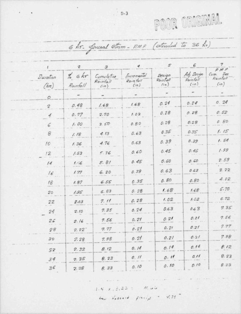
..
~
D-3. ..
' ' (-
.
. _ - _ _ _ .--
-- - - - - - - - - -
6A.r_ &. aal akm m!.s c&au # as 4). ...
.. . . . . . . - _ -
_ .--- - -
7. _ _ _ . . . _ _ . _ _ . _ -
I 2 3 ..4.__ ._ _ ,. .. .S
g 7- - _ . - .. _ . . . -
PMP_. .. .. ._,
Ewa$on 7o Ghr Cumuloise |beremen7d/... &..ci o sfoJf Gm. Das'
J /f R*. fall __ ..
,
Routfaff Foshtall Rainfo 'nRainfa/! ,1
_....__-](n_ . . _. .(,.;,)Eoind// pn) .!_ _ __ _O_n ) . . .tyn ).. b.|_rt)___-.. _ . _ _ _
'
. _ . . _ _ . . .. . _ _ . . _ .
j~ -- _
_- -
,_ _o i .
2 0.48 ./. c8 i 1.48 0.24 0.24 .O. 24
0.28 0.28 0. S2_ $ ._ _ 0.77_ _ .
2.70 1 02. . . . .. . . _ . . _ . _ _ . . . . . . .
.- . . . . . . _ _ . , _ .
C /. 00 3. sD o. B o 0. ?8 0.28 0. 80. . . . __ . _ . _ _ _ . ._ . . _ . . ._ _ _ _ . . _ _ . . _ _ . . . .
.
8 0,63 0.35 0 25 f. /C. . __ . / /8_ _ . _ . .
4. 13_. . _ _ ._ _ . . . _ . . . _ _ _ _ ._ ._
_ . .__. .
IO f.36_ 4. 76 0.63 0.39 0.39 i. S4. . . . . _ . . . .
. . . . . . . _ . _ . . . . _ . .
.
.. . . . . . . . . .. .. _ _ f 53E. 36 0.60 0.45 0.45 f. 99(2 __ ._ .
_. . .._. _. ..
. . . . .
14 f.GG S. 8/ 0 45 0.C0 0. co 2.59'
./G . .f. 77 6.20 C.39 0.63 0. C3 2.22
_ . - _ _ _ _ _ . _ _ . _ _ . . .
. . . . _ . . ..._ .__ ... , ___... . . ..._.
18 f. e7 s.sr 0.35 0. 80 0.8o 4 02.
. . . . - . _ . . _
20 f.95 G. 83 0. 28 f. 68 f.C8 E. 70
22 2.o3 7. // 0.28 f. 02 1 02 6 72
24 2 10 7.35 c. 24 0.63 0.43 7 3C. . . . . . . . .. _ _ _ . . . . . _ . .... .. _ . . . - _.. .- .._ __ .
. __
2C g. /g 7.56 0. 7/ 0. 2 / 0. 2 / ?.SG
26 7.22* 7. 77 0. 2f 0. 21 0.2/ 7 77'
- - _ _ _ . . .
_ . - . _ _ ... . . . . . _ . - _ _ _ . _ - -
30 2.28 7.98 0. 2{ 02/ 02I 7 98
*22 2. 3 2 8. /2 0. /4 c. /4 0. I4 8.12
3.4 . 2.35 8. 23 ' O. // 0. If 0. If 8.23..
0. 10 0. 10 01o 8.2336 2.28 g. 33. .. . ... . .. . _ ..
.
. .. _.. . . . .. . .. .. ..
. l . %' . r. 5. 3 :* * //. o G . .
d .I! " .4 s./ rza*d f/ssey ~
o
, - . . -.- . . -_ . , .

F - - __ .
. . .
g.4- .
.
.. _ _ . . . . . . . . . _ - ... ._.
/ 8 9 to || (2 r3 14.
Q H e in ko. k. 4no! '_ ._. OuwGs. . .c.m. . /.s%...lscrem.__. ?c ._ _.9,p . _..f...___;-
RunoR- o k.. of Mrotof ooram
O''] On) Go) (cfs) (cft) hrs hrs. 'AN
.. .O 3 . .
.. . . . - . _ . _. _ _ _.._. _ _ . _ . . . _ . _ . . . . _. .. . . . . . _ _ _ _ _ _ _ . . _ .
2 c. 04 0.04 19 0. 7C 0 f. 05 2.80*
- 4 0. IS 0 15 19 2.85 2 2.05 4.80.
G 0.40 0 2/ /9 3.99 4 5 05 6.80*
8 0.70 0 30 19 S. 7o c 7 05 g eo
to 1.0S 0.35 _ . ._ 9 6. Gs 8 9.05... _ . _10. B.o ._ . .1.. . . . . _. ..
. . . . _ _ . _ . . _ _ _
/2 f. 49 0. 4f 19 8.36 to it. 0S 12.80
tr 2.08 6. 59 19 11. 2 1 12 13.05 14.80
/G 2.66 0.58 /9 ff. 02 I4 (5.0S IG 80
18 3.45 0. 79 /9 /S.0/ 16 17.05 18.S0
20 S. /2 f. G 7 /3 3/.73 18 19. 05 20,80
22 c.13 /. 0/ 19 79.19 20 2f. CS . 22.80
22 23.05 24.800 G2 _. _19_ . _. . _/l_78 .. . . _ . . . . _ . ... . _ _ . _ _ .. . . _ .
. . 24 ... G_.75_ _ . . . _ . . _ _ _ _
gc C.95 O.20 13 3.80 24 25 05 '26 80
28 7.18 0 23 19 4.37 26 2705 28.80.
30 7 40 C. 22 ff 4 18 28 29.0S 30.80.
...3 0. f3 /9__ 30_ 31.05 32.80
.7.47.
*7532 _
-
.. _
2.09 3 4. 8024 .. i_64 0. // __ 19 _ __ . 3_2 33. CS
.- _ . . _ . . _ .__
_ __ ._
. .. . . .
2G 7. 73 0. OS /9 I* ?| 34 SS OS 30 80- . . . . . . . . . . . ._ . . . . . . . . _
. . _ _ _ _ . . _ _ _ . _ _%
. . . .- . .
.. .. . ___.. _ ...
. . . _ _ . . . _ . . . . . . . . _ _ . . . . . . . . . . . . . . . _ . . . . . . . .
. ... . . - . . . . . . . . _ . . . . . _ . .
. . .
. . ... . . . . . . . . . . .. .
. .
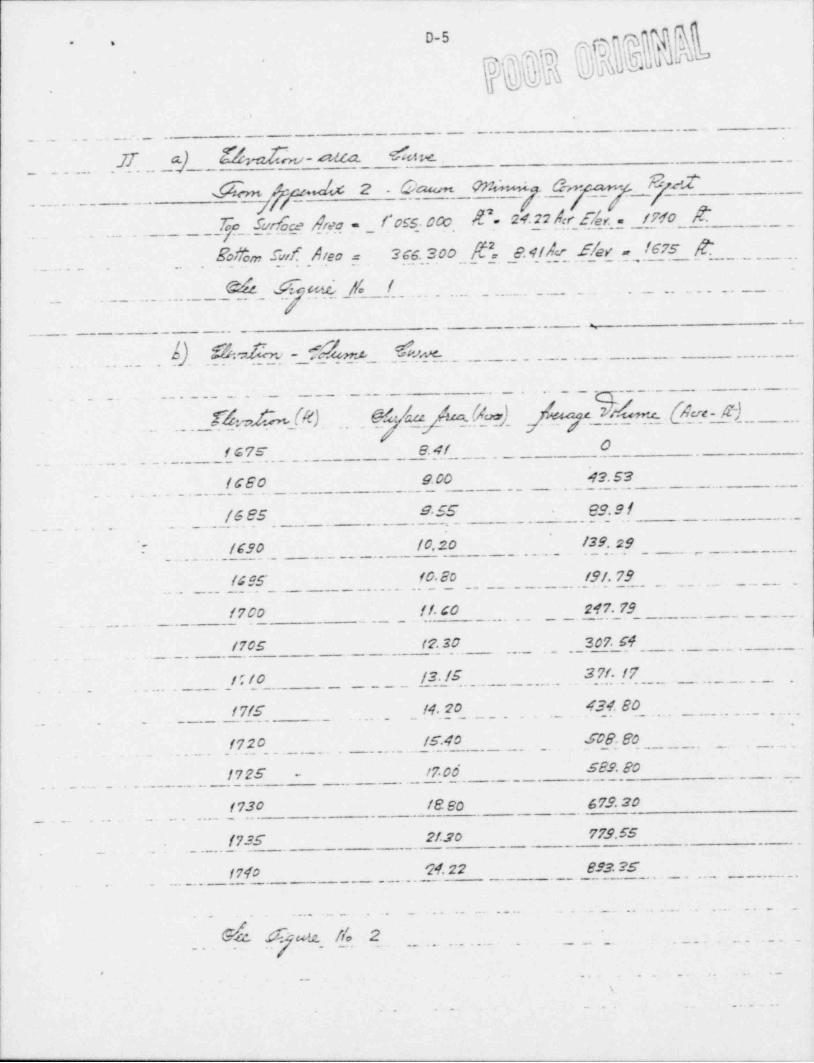
'
.
. .
. . .. .. . -.:..- _ ----- . - . _ . - _ - . ..,
_ . . .._. .f. - G- $$nu .afla. '$$c1ie . - - .
$m s<b4 2 0|atun WNs+>La & w .- . . . . . . . - -
- . _ -
/ --- -. -
/. . . . . .- _ -___&.y. S_u.r. _ce. d.u..a.l'oss 0 %.. S'.- 24.22 A...t E.~f1_ . /W. . O $d . -. . . _ - .
. _ . . . . . .. . So Wo m .5~w f. . A l.e o .=.3G.6.. 300..f. .,.. 2.4/Aer f/ey a 1675 [.. . . - _ . .. - - _ . . - - . . _ . _ _ . - . - _ . . .
-
Y. .--.... . .... - ... _ . - _ - _.
... . .. . - S.. F.cti.t:. _i$ | . . . _ . . _ . . ..
._ . . .
u_- _ _ _ . .
-- .-. ~
L). .% da.r.,. L.-.-..-. L...c. . - . - .- - . - - - . . - . - . _
. .. . . . .- - - - -
. . .. -- .
. _ . _ __ . _ . . _ - _ _ _ _
. . _ . . . _ . S. . _. _. . .L . @ ae- r). _ _. _ . . . - _ _ - .
'.--J. ,k (6). .
. . -.6.. 6. . _(.2). . .. . L..1 a. . - ...
.. . .
1 G7s' e.4/ 0
/CEO 9.00 42.53.. . . - - . . . . - - - . . . _ . - - -.-. . _ . . . _ . . .. -.
9 55 29.9 /_.. . . . .. .. _ _/. G 85 . __. - . . - . , __ - _ . . . . . . . _ _. .-
_
. . .-
.
.: /C90 /0,20 /39.29 . -- . . . . . . . . . . - . . . . . .-
. . . . . . . . - . . . . . - - - . - . .
/C95 f0.20 191.79
/700 if. Go 217.79
/705 17.30 307.54
1 to /3. /5 3 71. 17
17f5 14.20 434.80.
. . .. .. .. . ./.7 2 0 /S.40 S08So.---_. .. ..-..-. -. -
. . . . . - . . . ....... ...
/725 1706 S 89. 80-
.
f730 le 20 679.20
. (735 2):20 773.55-
- -
.. . - . . _ . .
|7fo '24.22 893.25
_ . . . _ . . . . . . . _ . . . . . . . . _ .. . . _ . . . _ . . . . . . . . . . . . . . . .
I... . . ' utz. flo- . . .-. ... ... .... .. . -. ._.. .....Ca 2
.
.
.
. . . . , . ._ . . . . . .

| !. .
" 'o. D.6
li oJ . .. _,
c,
*
*
,o* *,
<f Ii
'
$ =.*
i .
\ De t m-
!~ N )"_ _ _ _ _ _ _ _ _ _ _ . . _ _ _ _ _ _ _ _ _ _ . . . . _ _ _ _ _ _ _ _ _ _ .
! % N Di g$ M ' 4 4a % I b R %L -h |y .._
'3 .O '%*
h Il - ."I
8 ' ta-
%x |- -
b %. x a
5Q |- = e
i _ w s
!-
I iiI -
8
I.O~
|* I ,
I -.-.....-o- ,-I 1 gi e
= 0
,I e
D'1 .
..i - |
.I ll 8
i ei e
| e
-' '
__
S .MO w o*g m,w o- -_ _ - -
I
e
'
- 73 - pow 37.1.
'Ii -
!
.
v- 7- - - - , ,. --,, 9 4 ,S,-r t - - -*

,- _*
lM5,
I cfI
.
9
__
M. .
_ -
. -
. -_
-
o-
-
ort-
,.
. o. o
_ - o'
s5
as
u. *. .
. o.:
E.e o
s.
Mu ;
,
o .*.
i L 0 C'e.
D s 0 f 2C
%' V 8.a -
'
._ u ER ou
0 C N.A* 'r S 0
._ Y t
7 s .-
_
- EN' o
oE RO s-
W .M U9e
A o U GV os .LE /
O_
L Y_
~+ F
L 0_
04-
.
-.
o_
o9
s_.
~
- -
wS
t.
-'-
- ,
w._- .o
s
_
_
0 0 5 o'_ 5 0 7 s
7 7 G c1 I I t
_
_
_
-
-__
-
.-, >k Ds,
-.
-.
_
.
.
,
. ! <lJ ;, a i!2i Tl; T ;i . ;. h ; . ,

0 0-8..
93 i i
7D'la.h.!%DA]@ h
.
_ _ _ _ . - _ _ _ _ _=
_
- - _ _ . . . _ .
__Izz ._ - s d 4 _d.u. 6 iiMu~ .dafamo __
_., __
_ . _ _
. . _ . _
* L_. a6 s_afa.o.1 a. b . o. s.c cu a . .-
.. ._/ _... . _ . _ _ . .
.
b .= 38" . .. _$Y twnsual <.1 w -. . _ _ _
. .
. . _ .-
- - . _ . . . . . ...
- -. _ . . . _ _ . . _ _ __ _
. .. .. . .... --..._._ _
.T *f Oc1 /Vo <. Dec..'
Jon fil Mar Ay Mae Jun Jul Av,o. 1
M.0 deo sc.i css 70.s . 30.g/). . _._ .2.c.g 3_. _ .. ces._-. Co.s. . ._.._9.o o as. (._ . _
.. . Ar '.j. .
3. 04 " 4'48 ' C C2 " 707" c c9" s. 29 ' 2. 23" D.95"'
0./s ~ t.44'.. &. C''Of' (n,[ _~ -
Ark.j(m) 210' I.ss' /.54 ' O.!?" t.3G' /.29' O.39' o.Sf" 9. 87* /.59' /SS* 2.25"
2 .C 29.45 28G 29.45 26 5 2945 _2.9.45 28.5 29. 45 2E 5 29.45 _ . . .15d.e: a_.f(%. fi_ .29_45 -
. .- . . - .
- .r .. .- . .
-- ._. ... . . . _ . _ . . .
_ . . _ . . . _ _ . _ . . _ _ ..-- -
,, . gg._ _ _g.v.a .E. Mf?ow . . _ . _ . . . . . . . .Pmi. ..
___.___ _ ._.. _.._ _. _ _..7.~.fdh ,v.~. _,
_ - -_ /32_/. .JAN ._23.95 - _ . _ .f.54 _
29.45.---- . . . _ . . . - _ .
-. . . . . . . _
57.202 8. JetOS f. 26 c.//
- - - - - - - - - - - - - -
. .. .. - . . . _ _ . . - _ .
/4AR 86. GS f. 22 (.14 8 6. 73
i
_. . _ . A M. //S. 23 0.80 2.50 //3. 53
i t.tA Y /42.98 f. f6 3.82 /40. 32
. . _ . uN_.. . /.68_82_- ._. . _ _f .. _ _ _ 14 5. 0/ ..._.._-__..._ ._ _._ . .f. /3 4.9J
.. ._.
. . . _ .7
..__.
.____7
0.35 6. 33 188.42... . .u. -- -- 13. _4. 4GJ l. .. _ . . . . . - . . _ . -
.. . ... ._.. _...._ --. .. . - . . .
! . AUG 2/7. 87 - 0. SD 6:23 212. 14
240. G4 0.83 $. 02 236.45 . . . . . _ _
._. . ._ _ .. _EF *
ocr 2._65.3_0/. S7 3. 18 2Cf29
---
_. . _ _ _ _ _ . . _ _ .//W 292. 73 f. 97 0.96 2 9 ?.80
.
225.COj | DEC 223. 25_ . ._ _ . '2. 35 . . . . _ . . . . . . . . . . . . . . . . _ . . . . . .
t
... . . . . . .
. . . _ . _ . . . - . . .. - . . . _ . . . . ...._ ._. - . . . . _ . . . . .. . .. .. . .. - . . .
. . e. .. . __ ._ . ,
$. .o . ..._. ..e.
. . . . . .
. -.. .. . . . .
! _. .... . .....
.
| .. . . . . . .
!t
I

e 09.-
$ =>j,
, ~ ,
Tin 0W A *. E . Ostfow*. . . . ... . .. _ _ _ ___ - . _ . . _
SSR 3/1982 JAN 355. OS 2.26 -.
FEB 3 83.9/ f. 84 0.17 28S.58_ . . . . . . . _ _ _ _ .
_. . . . __ . . .__ _ _ ._ __ MAR- - - 4_ff. 03 f. 78 .__.f_Gs 4/C.Is. _
4ff.1f. /G 3. c3 .....8....._......__..._.. ._ App .. ...._4_43. CS-- _ _ . . . . .. . . . _ . . _ _ . _ _ . .
MAY 470. G3 .fG8 .s'52 4'66.79
!uN 495. 29 !. G3 7. // 489.8/ .
.-. .
JUL S/9. 26 SI 9. f3 S/0.58 *
_ ._
. . . . . . _ _ _A..UG E40. 03 0.72 8 93 S3f. 82.. _ ._
-- _ . _ - .
sep S co. 3 2 f.13 7 If .SCf.3/.
S83.7 4. 54 58f 49. _._ __ _9 2.24=_Oc_r_-__ - -
-. . - . . . . - . ._ 7'
Nof 609.93 2.83 f.38 6/f. 49.
sDEC G40. 89 3.38 444.27~
19 83 JAM G73. 72 3.27 G7C 93~
_
FEB 103. 59. 2. G7 0.24 706. 02
MAR 735.47 2.59 2.42 735G4
Apg 7C4./4 f. 69 & 30 VC0. 53
MAY 789. 9 8 2.44 - --- - . ._8 OS 789.37- . . _ . _ _ _ . . .
. . . . . . . . . ..
JVM Gl2. 87 2.38 /0.38 80f. 87.
_ .. . ... ..t _ _834. 22... . _0 7f 13.38 82/. 68/u_
,_ _ _- . -
| AUG BE/.13 f. 0f /2.90 839.27,
l
_. __.sEp 8SY 7Y I' || |0' ES 05#' IS. _ . _ _ . . _ .
8 8 5 3 f / o.s<.ocr 888. 64 2. /9 6.49
.. . _. . . _ - - - . . _ _ _ . . _ _
.. . . _ . . _ . . . . _ . . _ . . _ . _ ._ . . . .. . _....._. ..._ . . _ _ _ . . . . . . _ . . .
.
. . . _ . . _ . . . . . . _ _ . . . . . . . . _ _ . .
;. . . _ . . . . _ . . _ . ... .. .
: .. . . . . . . . . . .. __ . _ _ . . . . . . . . . . . . . . . .
i
. . _ . . . . . . . . .. . _ . . _ . . . ._ ...... .
..

. "MnMak '*
.q. . . . ..,,, ,.... _. .,, (*'
..l....--
_,;,)
_ -
. .
.J ' . _ _ ! . . . . . . , , ,
tG'
-
__
;-- ,c
1,.. . *
.. , . . .{ , -
*g6*
,-
- - ..
.
: : ..--__
m.;k,-
r_ . _ *
_ , ,,.g
L . . . ' ' * ' . p .. _b . g .. ' * * 18s. *.
I .~*~ T. 7 0 - . l ,' T~ "
',{**L..._..__..,''_.i.',..._m,. i. .vw. . . . _ . ....t,,,,,.*
. . .... . .. . . .. .j. . - . _ .. .
... . . sj ,
y k8* .g ( fe
o 6. ,-
9 1 1 '' '*' | ~ ! '".W 9 6 ' i! ;.' ,1 ~ ~ . l.
* '. ! @ I ' * ~ [ W i* ( .g g4 .' - ~- -~ ' ' - :: ;- : :,
''g * % . r~s, ,
.! x ;, ' -- t ::'..: % s:',
-
" ,N 2
_ _ _ R 4 .,tu g_-. ___ .
--_ .
,
t*~,Cc t . t f, ,. . i,
: ~ --
n. :*~:: :: J=;: n .
- -
. .. . *
.. . . . .
.
q..
=' - .W. _!. . ._
|.. . O
~~ ' ' ' * *
_p_ *\._e _tr L .
.
a|. .
L, Q' f ,'*' W . . e. ,.. -- _
M.. s. t _ir. h at. k.
: , 3, 7 . ', ).' ..,.*_hI .o.._...... . = +-. . . . . - . . i- ..
n -..
.a v.. - --$e.
; i.. . A e .7. 4
v .- . s. *1 -
p..~ +
= ._ N . s , . '9{ . . - . ,; . g = p. ,. [ _.. . * - _,,,,,n-- ~-
* *. ., ..
,, . .-
.s....,. . . 1_ . . . .
-} .Lp, i
't ~ -- .-,4,... 4___._[_
-_ > _ . ,.
_ 1. . 27. . . _ . . . .
.__. . L-
7 . E(q- --
.2_:. _ _ . . . . . a e_',
.
A,..:. 4%r.. ; . . ,. . -
,_3 . J- f. . .. a n f (-t, , . . . . -*. ,
'
w,, _ y .I j.,_ b X* i 4
..,i. 3 ' 4
.. _ . _ . , * .* 4 ~.
|a .?.. . _".' !. _* * .s. . g, .. . . e - g 5. : .. 4, . \a . y.-- ,. ,,
.
* c . _
v*
. . .. g .
*O U.
* , .
.-
_ I*s b. -- i
9 +7 .v.q emeeseemd aes,
mome u.ma- ,esensiond __ _ _ _ _ ,_e4 - .c f e. _ _ _ __ . L. _**
._ g --
* .,*. 6. . .
. ' . ( .fs
.'T7/, -. . . . . .
, . _ -
heg. ,
& 8% : g., (' ,,,,
. s. .
s. ,e . N . .. y<$'y | , .-.
.. * .v! 9
' *g f- . . =t ] '; . a._ , 7 -'. . ** * .
4..
; ;. Q,,.I l :
:==-
-
'" I eI..'-
D __ _ ,,.,u_ _ i -'
h_. .!--. _
<*t .is.,!. . n8
d Q M e'_ . _ _ _ _ _k._l. < . , 3t. ) |, __ o- - . _ . . _ _ .
f I 'd 5_$_ I. , [__ e : o lla.. .:|g! Ia
z,1.,.*3 h [*
. -
u, - . - * 3 ,a. 3.n ,.
t :- t.; .< - .,.. ..._.- _.._s.e.-
,_
g ~. . . -_
'}.t..
..p -.,3. a . . . e .e.~ .
n< | '?"
g
~ t O. 6. i ?.~
*~.. .
j j+-. .se , . - c- wt ,..g <
.*a- *
} ]* g ... : w' . ) ~* - ~* T . .;_ y . ~ " - *
v.. . 3** .a,,..
e,=- ..
.l 9 _ ,
.
1 .f.'iA_ !'.i.
8 e , .._. . . . I. . , ..> e'Ig 8 . . .
8b e i %% ay,. ' m.. O_p. % .g
]- . g , , y , 3 ;, , .
.g. . .. T* J -
Y $ g8
O. .
*!(4 1 ; g. . y , a . p.... .. , w ,vmg 4 .,,,. . p,. ;, y.;
.
, _ - -$
15 , ,,, .,. :. - .A -% <.o-. '
y.? M.M. LJc :__% i7 -
*
* . .i
'fjik- y- - b. . a . _ . s. - .,g ' e ;- ] it_ , s, ,
,. -o : .r. . .e 3 4. , .s._. . _." --4 :.
1 ; o 2 .
t-
- 4!,<; 1-
" . . . .: -
s .,..
y. 3j- .|.
,9 *@ T WE MftS S#G._
-
M.D, .
*=
T*r.e 9f* *7}';_-e 2
-
't_ O --_f- .'g .s... ~w 4*
S-_._ . _: - .
2_"' ''
D '3 f 9 o. t .- . . .
!dJ I g i.,'e.t,'
[. i | |#
# | g, |g , I.,
g:'.- ' 't i
'[(| f )N q,
. .
, ',i
'l '|'
r .i., ~. } t, fi' -
f. . : - <, .s ,..,[t
8 Vt j [ *3i ..
.r >I
.e !f f
j >e
I g Q j 71 > %. *
43 g b4 > " , .- e
, ' ". - % j 8! . I! * $ I ) *' *.
? 1IT 4 . 3 * *61 - i m., t e . ..
,
} 1? 4 d*** ..( J i
c.*I'v
ke M 1 . . . - - , ..%t .-
i. t/ ._ i.. _ . i|.. i, - _ . . _ .,
. _ _ . _ _ . | -
,. , .
. , . ..f.y,, _ ,, i -,. , ,
9 ,
..,

. _ - . . - _ - . .. -- _....- - - . . . . _ . - _ . .. __ - _ - _ _ . - _ . _ _ _ .._.-. - - . . - . = - _ . . .- -
N
i
]APPENDIX E
5
!
DA$N MONITORING PROGRAMS
t ,
DATA -
ii
The following data is presented as follows:!
]
Table #1 Surface Waters'
.
Table #2 Groundwater'
Table #3 Seepage AnalysisTable #4 Air ParticulatesTable #5 Radon Gas'
.,
! Table #6 TLD and VegetationTable #7 SoilsTable #8 Special Report on Station 2-2Table #9 Drinking Well Analysis
,
.
I
j
J
>
i
.
I
I
e
J
e
)I
4
i
J-- w ,,,,-~,,,---,-,.,--:- -sv..,.m-.1,~+__-. ---.- -,,- ,,-. +_.....,,-enm-....,-+-,r,W.----....----,vm,~ ,..--.m ,, . * , - .- - e

-~
TABLE 02
GROUND WATER ANALYSIS _~
Uncontaminated Dawn MonitorSprings
_
WellsParameter Low Avg. _ Hip Low _ Avg. _HM
TDS 128 202 334 62 665 5323
Sul fate 5 7.16 50 0.1 302 2619.
Nitra te (.05 .62 2.22 .01 3.45 66.9
aelenium .005 .006 .01 .005 .007 .04'
Uranium .001 .004 .018 4 001 .01 .10
Manganese .01 .059 .15 .01 .27 1.8
pH 7. 3 7.8 8.9 6.7 8.0 10.0
Lead .001 .016 .02 4 .02 .03 .10
Zinc .002 .018 .035 .001 .037 .2
Arsenic .001 .002 .003 .001 .008 .15
Copper .002 .012 .02 .01 .023 .18
Ammonium .02 .075 .15 .01 .93 4.94
Chromium .01 .033 .10 .01 .05 .20*
Rcdium -226 (total) 0 0.083 4.1 0 1.53 9.2
Radium -226 (dissolved .3 1.15 2.1 .01 .38 1.0; Cadmium .001 .003 .01 .001 .004 .02
4 0002 .0004 .001Mercury - - -
Chloride .5 3.54 7.0 .10 4.18 22.0~
|
(all values expressed as mg/1, except for Ra -226 whichis expressed in pCi/1)
.
| .
|
l -
|1
|
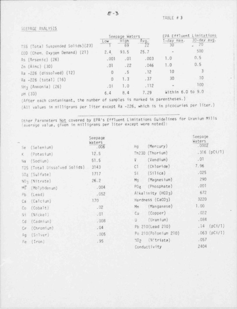
-.
E -3 '
TABLE O 3i
SEEPAGE ANALYSIS
Seepage Waters EPA Effluent Limitations ,
Low Hign ' gAv . 1-day max. 30-day avg.TSS (Total Suspended Solids)(23) 1 69 22 70 20 i
I500C00 (Chem. Oxygen Demand) (21) 2. 4, 93.5 25.7 -
As (Arsenic) (26) .001 .01 .003 1.0 0.5'
Zn (Ainc) (30) .01 .22 .046 1.0 0.5
Ra -226 (dissolved) (12) 0 .5 .12 10 3
Ra -226 (total) (16) 0 1.3 .37 30 10 .
100 |NH3 (Amonia) (26) .01 1.0 .112 -
pH (33) 6.4 8.4 7.29 Within 6.0 to 9.0 .|(After each contaminant, the number of samples is marked in parentheses.) |
(All values in milligrams per liter except Ra -226, which is in picocuries per liter.) |
Other Parameters Not covered by EPA's Effluent Limitations Guidelines for Uranium Mills(avera'ge value, given in milligrams per liter except were noted):
Seepage Seepage
Waters __ Waters-
Se (Selenium) .006 Hg (Mercury) .0002
K (Potasium) 12'.5 Th230 (Thorium) .316 (pCi/1)
Na (Sodium) 51.5 V (Vandium) .01
TDS (Total Dissolved Solids) 3143 C1 (Chloride) 7.96 i
504 (Sulfate) 1717 Si (Silica) .025
NO3 (Nitrate) 26.2 Mg (Magnesium) 290
'6 (Molybdenum) .004 P04 (Phosphate) .001,
Pb (Lead) .052 Alkalinity (HCO ) 6723
Ca (Calcium) 170 Hardness (CACO 3) 3220
Co (Cobalt) .02 Mn (Manganese) 1.00; *
| Ni (Nickel) .01 Cu (Copper) .022
Cd (Cadmium) .008 U (Uranium) .084<
Cr (Chromium) .04 Pb 210(Lead 210) .14 (pCi/1)
i Ag (Silver) .005 Po 210(Polonium 210) .063 (pCi/1)
| Fe (Iron) .95 NO2 (Nftriate) .057
iConductivity 2404
|1
4 .
1
!-!
l
!
?~ . _ _ . - - , , _ . - . . _ . . , . . _ - . . . , _ , . , , _ . . . _ , _ . _ , _ , _ , _ . . . . , - , _ . _ . , - _ , - . , _ . . , . . _ . . . _ . - _ . . . . _ _ , , _ - , , - , , , . - -

- - - =___ _ - . .-_ . _ - _ .- . . - - - - . . - _
r' ^
C -Y | A3tfyg- -
.
.
fi @ d EJN$) [Lu fD
dtn t, :J -
.
--.. .. . . . . . . . . . . . . . . .
.;
,. .
_.;.,.
e. . _ _ _. .-- - . . _ - _ _ . _ _ . , ,
., a . . - .. -. _ . . . . c. .
-
. . ,
=..I .i,
t. i..
*I.J .,. w %; . . -#. . .- . ., _ . , _ .__.._
_. ,_..
. :- , i. .. ..
0 , ,s . . - - . t ,. . . - . .,
- ,,~ ~ . . _ . . . . . . , . ~ ~ . .
3,p._...._,--------=. _ _ _ .
t- . --- e . - - . , . i3- a >N . 'e . .. t, e g 3
)'
A 4*G. A '
.|.'
% 'I* * .
* k, |* |=
'..I,2 GM I * e
w _ a 1 ,
.e-..., e _ . ...
' |4 e e. ..e
g j. 7. N* *t ' .t '* '9 '9 ' .t ' .S ,
gt r . . . . ...e e. y . n . e**g . y
I. $ *-
F 4 - so y e
f..~..._.c. . . . .
. c . .. . .-y . . ~ . ~ . . ,.-; .
.- -- .. _ _ . . _ . . _ . _ . .
g4a* .* ,
. c- 3 ,- ; na=. . *
b p % $ 4Re g
f8
t.-_...'. . . ,s 1 1
- -)sa *ae
-!. . 4 i*
y*e s N
tt . i. N- =m. s, ge !a
.Y........ f.
$ ---A - - =.a .. .%-.% ..
u- q_ 1 d . Q. . .
I |. . . . . . . . . . _; .
s ;e
h ; $.2 D,.
.e=I v. -. .4 % *t .,%, E s'gu
is 4w
..- 2 .8 .. . - - - t -* ' = ' .,*I e J, -- o .' y -- ~..*9 . ~ . .
q kE .1,1* I k .I. k. k. *e*
,. o - g _ ,es. ~g-e e
e - {c.fmem e . . ~ . -.-~..~..w..- . ,.
*-. .-
.
. ..
,. t., T a. . n, ., . . . . . . _ (9.
ee, ,.** 9 ), f A & '9 W
I * a*g . q,4 s - '." .
,* 9' ** ,
w -t-
"a E .$ f
e s3* 1 e.g.***E
e e ,.t , %'s
~
-..z, a , *:, .. . o ;-. - ;6 ,
J. . .- .- <, -,. ,. ,- .- . . a j. ..
m a e J 7 *. '
1 , a ,s,-E .- = a w
~
a
*. a .
. ..o. . ...s. ., js a .e e t
. .u s . *3, e_.-....-.ms 4 #-
I_i_*s - .p._. --. - . ,.
a..,
O. E . , .* D _=p- * *, I ar
* * ** a -Ts !' . * -"e *. : +
i* .4 *
a eJ'.a.6
0- * 1 e s|9 ,
* .) 4 o ,'* .
't t * . . . . ~ ,w.a . W _ , % ~.. . n . e - . ,. s, - . . . . .* e *e ay g
, "F f ., '9 e, *e 9 gwa = . . g 'g
% .. a p*. . F e Q m *, o . se g .e ,T y g ,e. .
dj* * 4* a g.-.. , N
.*3 -. . . _....e.... e ne.eg _. ge .
a . 3=
..= ne 3 -...-.... -_ -_*e *e
.k
p*y* I ,% ~# *e
m a A ;*a Q 1 *
s. 3 $, e. h ) %..
w .-..
1
s. . . . - -- -. - . . . ,. 6r $
.4.o > a. 3**
<. O , .. -- -- -4. .. .. ..
*g ) e-.-e..
* .3 g .. . . . . . . . - . - . _ . *y .
= -
.s s- - . . .e3> dT. se ..o
M e.e
# 4 N d N d MS1 e sC = as
e 2 e a e*4 **% *
n, ..-
* ''S a g .,
" W $T *
Q[ .
WW \
. . - . .
V -.' - - " gT-g w p f- -av--Mwew --wr- vw .- -y -'~twp- $w- gp.-R Wt". * # W ?" -* *--9T''*P "# *T # " * - - ' ' u T *
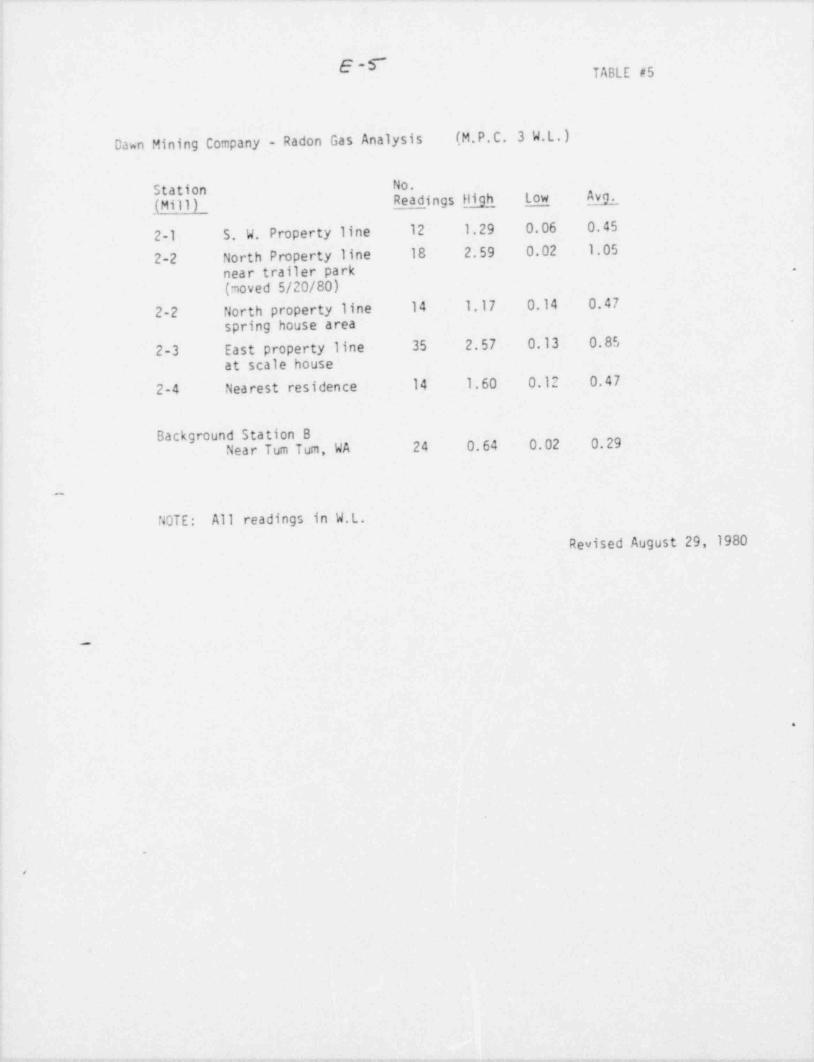
E-f TABLE #5
Dawn Mining Company - Radon Gas Analysis (M.P.C. 3 W.L.)
Station No.
(Mill) Read _ingsljigh low Av2
2-1 S. W. Property line 12 1.29 0.06 0.45
2-2 North Property line 18 2.59 0.02 1.05near trailer park .
(moved 5/20/80)2-2 North property line 14 1.17 0.14 0.47
spring house area.
2-3 East property line 35 2.57 0.13 0.85
at scale house2-4 Nearest residence 14 1.60 0.12 0.47
Background Station BNear Tum Tum, WA 24 0.64 0.02 0.29
NOTE: All readings in W.L.Revised August 29, 1980
_
G
.
4
t
y . _ -,. .
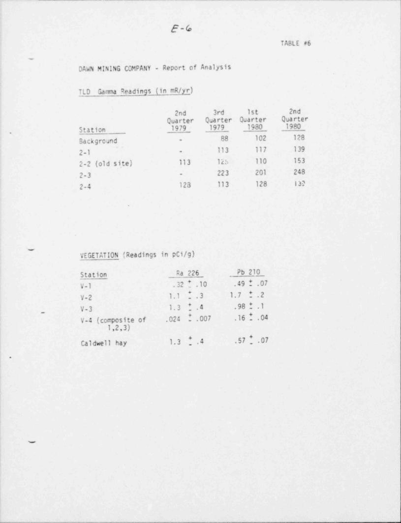
.- -.
t
1
E-6:
TABLE #6|
DAWN MINING COMPANY - Report of Analysis;
.
'
j TLD Garmna Readings (in mR/yr)i
!
! 2nd 3rd 1st 2ndt Quarter Quarter Quarter Quarter
Station 1979 1979 1980 1980.
88 102 128Background -
,
113 117 139'
| 2-1 -
2-2 (old s1,te) 113 125 110 153,
223 201 2482-3 --
1 2-4 128 113 128 130
,
.
*
i
!v.
VEGETATION (Readings in pCi/g)!
Station Ra 226 Pb 210,
[ V-1 .32!.10 .49 ! .07
| V-2 1.1 1.3 1.7 1.2'
V-3 1.3 1.4 .98 1 .1_
[ V-4 (composite of .024 1.007 .161.04 -
1,2,3)
Caldwell hay. 1.3 .4 .57 1 .07
|-
I
w
L
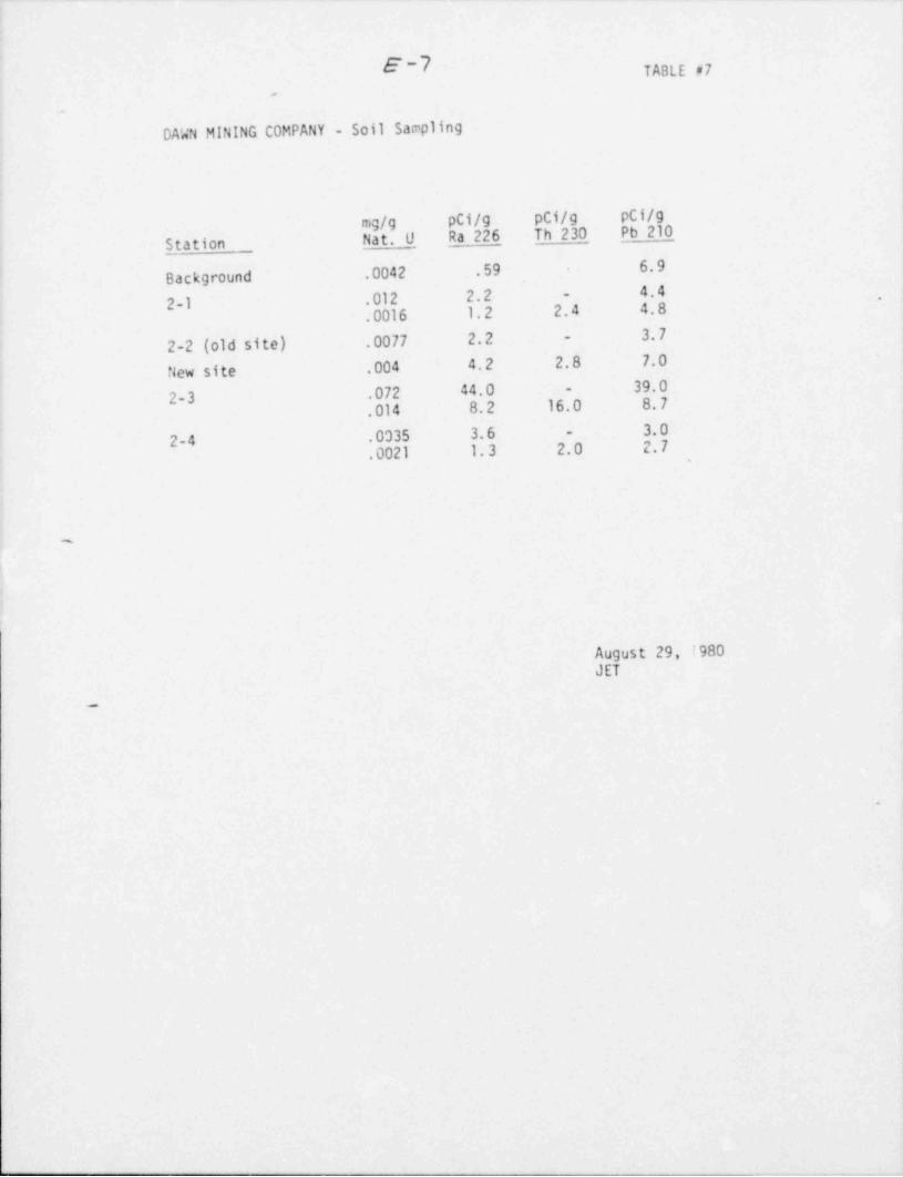
!
!E -7 TABLE 07,
.
DAWN MINING COMPANY - Soil Sampling
mg/g pCi/g pCi/g pCi/gNat. O Ra 226_ Th 230 Pb 210_
Station __
Background .0042 .59 6.9
4.42-1 .012 2.2 -
-
.0016 1.2 2.4 4.83. 7
2-2 (old site) .0077 2. 2 -
New site .004 4.2 2.8 7. 0
2-3 .072 44.0 - 39.0.014 8.2 16.0 8.7
3.02-4 .0335 3. 6 -
.0021 1.3 2.0 2. 7
,
,
i
August 29, i980JET
-
6
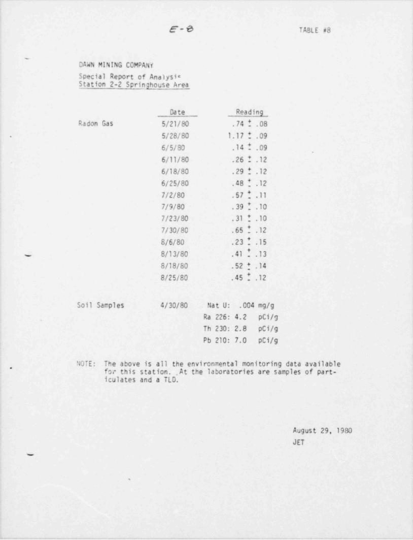
- _ - . . . . - - - - - . . _ - _ . - . . - . - . - .-- . -.. .._. . . . _ - _. -_
|<
I E-6 TABLE #8
:
4 DAWN MINING COMPANY
Special Report of AnalysieStation 2-2 Springhouse Area
Date Reading
Radon Gas 5/21/80 .74 ! .085/28/80 1.17 1 .09.
,
; 6/5/80 .14 I .09,
|. 6/11/80 .26 ! .126/18/80 .29 ! .12
; 6/25/80 .481.12! 7/2/80 .57!.11j 7/9/80 .39!.10
7/23/80 .31 ! .10i
7/30/80 .651.128/6/80 .23!.15.
8/13/80 .411.138/18/80 .52!.148/25/80 .451.12
Soil Samples 4/30/80 . Nat U: .004 mg/g
; . Ra 226: 4.2 pCi/g
Th 230: 2.8 pCi/g
Pb 210: 7.0 pCi/g;
NOTE: The above is all the environmental monitoring data available -
4* for this station. , At the laboratories are samples of part--
iculates and a TLD.
'.
!
- August 29, 1980
JET
-
%
.
, , , n y-, ~ - . . , - - - .-..,...ry. .. ~,,,,ym. - -.,.._ry. , , , , . . . - . , . , , - - , ,. -.-c-- .. , . . . . - . #, ---_,. .. - - , , .~ , - . - . m

'
e'- 9
f@Lg@ep~;0F}wus pi-
.
..
,.T O ' s $. C8. S. ~* 2 7 8 3 3 3 * 8. **- . ..- ..
8.; 2

s.
.
APPEhTIX F -
COMMENTS TO DEIS(October 14, 1980)*
.
.
e
D
e
D
.

.
Response to Coments on NRCInput for DEIS - Dawn Mining Cornpany
Mill Tailing Expansion Project
,
t
'
e
t
|
.

Response to EPA Coments on NRC Input forDEIS - Dawn Mining Company Mill Tailings
Expansion Project .
.
COMMENT:
Page 2-3. Item 2.3, first paragraph. The last sentence says thatgrounowater flow is reported to be " modest." This is in apparentcontradiction to page F-2 (paragraph 3) where the groundwater flow
- in this zone is referred to as "significant."
RESPONSE:.
The description of groundwater flow in Section 2 for the purpose ofthe assessment of the proposed below grade pit was not intended tobe quantitative since no seepage is expected from the pit. Theproposed pit is above the water table and fully lined. The groundwaterregime will be quantitatively defined as part of the environmentalassessment associated with the Dawn Mining Company license renewalwhich will evaluate in detail seepage from the existing impoundment.It should be noted that Appendix F of the DEIS is a report by aDawn Mining Company consultant and will be deleted from the FEISsince it does not necessarily reflect the position of DSHS or NRCstaff.
COMMENT:
Page 3-2. The f1gure indicas j that Dawn has very little propertylef t between dike edges and the property lines. I understand thatother states have required mill operators to acquire sufficientreal estate to provide a buffer zone in which to work to clean upspills or windblown tailings. Based on studies at other mills wewould expect to find land areas contaminated by windblown tailingswhich would be 3-4 times the area of the tailings piles.
RESPONSE:
! The staff's position is as stated in Criterion 8 of Appendix A to10 CFR 40: " Milling operations shall be conducted so that allairborne effluent releases are reduced to levels as low as it-
reasonably achievable. The primary means of accomplishing this -
shall be by means of emission controls. Institutional controls,
| such as extending the site boundary and exclusion area, may be'
,
l employed to ensure that offsite exposure limits are met, but only~
af ter all practicable measures have been taken to control emissions,
at the source." Dawn will be requind by license condition tocontrol blowing of tailings through implementation of a documentedinterim stabilization program. If weekly inspections, which arerequired as part of this program, or environmental monitoring show
| the progr6m to be ineffective, then the need for a better controlprogram and/or extension of the site restricted area boundary willbe considered.

- _.
-2-
*
COM'4ENT :
Page 4-4, F. I would regard the applicant's reported stack emissionrates (page A-4) of 0.0015 #/ hour (dryer) and 0.0011 #/ hour asextremely unusual. We have measured the emission rates (usingstandard EPA methods and equipment) from all of the New Mexicouranium mills and from one Colorado mill (see attached). Only inone new mill have we seen one measurement on a dryer stack as lowas the numbers reported by the applicant. Older mills and even asecond new mill more typically had emission rates which were a few '
hundred times those reported by the applicant. Obviously, if theemission rates are on the average higher than reported, offsiteexposures are elevated accordingly. I believe we have suggested inreviews of previous drafts of this EIS that the actual data be madeavailable in the EIS for review.
Page 4-16. In view of the apparent difficulty in 40 CFR 190 compliance,I would strongly suggest reevaluation of the reported yellowcakepackaging and drying emission rate data.
RESPONSE:
The dryer and packaging stack emission rates used in the radiologicalassessment were based on data submitted to the NRC in a January 30,1980 report by Alsid, Snowden and Associates for Dawn Mining Company
. entitled, " Atmospheric Emission Evaluation, Dawn Mining RadionuclideRelease Rates, Ford, Washington." A copy of the table from thisreport giving data on yellowcake releases is attached. Althoughthe reported releases are low, the staff regards the data as representativebased on the following:
The mill throughput of 430 metric tons of are per day isa.very low in comparision to other mills.
b. The magnitude of the reported releases is not unique inthe industry (e.g., Schio Mill, Seboyeta, New Mexico).
The Dawn process does not produce a fine dry yellowcake,
c.powder typical of most mills but instead produces yellowcake'
pellets. The pelletizing process used by Dawn MiningCompany in their drying and packaging was observed during ,
a February 1980 NRC site visit and found to be extremelyclean and dust free in comparison to the typical dryingand packaging operation at uranium mills.'
COM'4ENT :
Page 5-3. I would suggest that the data reported for the UNCCnurtnrock dam failure may be partially in error. The reportedfigure for solids released is based on an engineering survey of the
[
..._ __ - _ _ _ - .- - - . _ _ . - . . - - - .
3--
eroded area of the solid tailings beach. It does not take intoconsideration the suspended solids contained in the liquid fractio.ireleased. As indicated on page 5-2 and footnote, it is usuallyassumed t'1at equal weights of solids and liquids are released.
'
Th{s would indicate the solids loss would have been more nearly 9 X,
10 pounds for the Churchrock dike break.~
RESPONSE:
As indicated in the comment, the data for the solids released fromthe Churchrock dam failure as presented in Table 5.1 did not account'
for the suspended solids in the liquid released. Bascd on available,
total dissolved solids data, the table has been revised to accountfor this.
COMMENT:
Face 5-4. The val.ues in this table differ by a factor of 100 fromtnose given on page 7-4 (which appear more reasonable). Suggestchecking units.
RESPONSE:
Table 5.2 has been revised to correct the typographical errors inthe concentration units.
,
%
, .
O
e
e
=w--y 3y T- w -a-om - - - +_w--,.,.-.y-, meg y -y ~ p ,,y --,-,..ay-.m g g . - 9 , - 7- 7--ye * - -3- - 3

i
, - . . _ . - _ - - _ - . - - _ _ _ _ - . . . . - . - - . - ._ . . - . . . - -. . _ , _ _
RESULTS SUMMARY4
|DAk'N MINING AT TORD, h'A
Septo.bor 25, 1979 99*g *.0
' '9 '
V k.
] N Ju w @ _ e3.,
Ju a :
(2)i (1) PARTICULATE URANIUM (3)
SAu?LE ASA ASA P ARTICULATE I".ISSION FILEASE PADIONUCLIDE
ID LAR SAM? LING CONCDITRATION, RATE, RATE, RELEASE RATE, t
(cRIGIN) # FUN # (GR/SCT) (L3/ES) (ga/HR) (n Ci/HA) ',i
__
i
Crusher1 Exhavst 4149 1 .013 1.476
1-
CrusherExhaust 4159 2 .001 0.125'
,
t' I .007 .801 10.165 ------- ,
AVERAGE'
3arrel.
Tilling .
Exhaust 4169 1 .008 .054.
EarrelTillingExhaust 4179 2 .007 .051
Ra-1.60.006 .053 0.425 Th-1.27'
AVEpaGE*
.- - -
I Agitator
3- Exhaust 4199-1 1 .001 .020
g,
Agitateri Exhaust 4189-2 2 .006 .112
Ra- 6.12' *
,
.004 .066 0.210 Th-6.99AVERAGE
Dryer! Exhaust 4199-1 1 .006 .050
-
i DryerExhaust u199-2 2 .C04 .036
Ra- 23. 9,7
AVT, RAGE .005 .048 0.679 Th-19. 7 ., ,
,
.
(1) GR/SCT (GEBo T,1.0 atm press . , dry),
!clate 453.5910E6 ug/lb = (gm 'U/hr)(2) u r -urar.iu=-s amele lb-o xx nr
] ui-sorticu1 ate sa= pie.
S c ,:e eenmee as m t tr= musee ASA ~=,-
~ ;- bi late _ -i!.iE ! gli nan :arries.tr$3 22 -.E-9 C.rie:-sa ;1e . (nci!hr)," :
|- g-;aruculate sa .;:e
:sdiu - 226 and he,rir - 2n-
d _i
-_

._
-3-
RESPONSE:
' The revised details of the rip-rap, filters, cover sand and linerhave been incorporated into the FEIS as Figure 3.4a.
COMMENT:
3.2.2 Seepace Control.
j The quality assurance program covering all aspects of liner insta11atior.was submitted to the D.S.H.S. in July,1980.
RESPONSE:
In light of Dawn's change in liner materials from Hypalon to HighDensity Polyethylene, submittal of a revised quality assuranceprogram for liner installation (new specifications, testing require-ments, etc.) is required as part of the addendum to the pit construction. specification document, required by license condition.
COMMENT:
3.1.3 and3.2.1.7 Embankment and Pit Construction
| The A.S.T.M. - D1557 test method cited in this section has beenchanged at the request of the D.S.H.S. and N.R.C. The embankmentwill be compacted to an average of 85% but not less than 30%relative density as determined by A.S.T.M. D-2D49.
'
| RESPONSE:
|Dawn's commitment to adhere to the requested compaction criteriarevision has been noted and incorporated into Sections 3.1.3 and
( 3.2.1.7 of the FEIS..
,
'
COMMENT:,
| 3.2.3.2.1 Failure Modes Associated With Impoundment Elements
Dawn stated in its September 16, 1980 response to the NRC Environmental'
Assessment that to require at this time a rock cover over thetailings mound would be premature. The Ford, Washington area isnot a desert such as that found in New Mexico. The dense forest
|
- - - . - ._
.
-4-*
.
and underlying grasses surrounding the site is evidence that aproper cover ;an be established at the site. Experience withrevegetation efforts in the intervening years at th: mine site <
(initiated in 1980) and on the spoils stockpiles from the newtailings facility will indicate what course of antion to take atthe time of final tailings reclamation.
Dawn has roughly estimated that to cover the site with one to twofeet of rip-rap with rock from the mine will cost in 1980 dollars .
froa 52.5 to 4.9 million. The calculations are as follows:!Surface Area: 7497900 ft 3
Volume of Rip-Rap 7497900 x 2 feet = 14995800 ft3Conversion to Tons: 14995800 cubic feet + 16 ft / ton =
937238 tons
Cost: Actual 1980 Mining Cost $1.11/ tonActual 1980 Hauling Cost 3.15/ tonEstimate Spreading Cost 1.00
Total Cost per Ton $5.26/ ton*
Cost for the Project:937238 x 5.26 = $4,929,869.Say $4.9 million
(If only one foot of rip-rap is used the cost would be $2.5 million.)
Expenditures of this magnitude should be only decided after dueconsideration and study; not on an opinion that is not substantiated.
.
RESPGNSE:
Dawn's estimation of the cost of the required rock cover is somewhatinaccurate. The NRC in nest cases would require only 6 inches ofrip-rap over 6 inches of bedding material on the exposed sideslopes of the reclaimed area. This would greatly reduce the surfacearea used by Dawn in the cost estimate (the entire reclaimed area) ,
and in combination with the requirement of one foot thickness would-
*
result in a cost estimate much less than Dawn's lower estimate of2.5 million. A 2-inch thick layer of medium aggregate might beacceptable to the NRC staff for placement on the flat top surfaceof the tailings area. It is likely that an acceptable medium,
aggregate could be found near the site or during excavation of thealluvial materials for the proposed tailings pit. The exact requirementsfor the rock cover can only be determined after Dawn has shown howthe reclamation cover will tie into the cover over the existingimpoundment and developed and submitted a pian as required inLicense Condition No.1.
.
-. . - rv+ - - - * v 4 --- - -- -

.
-5-.
The hRC staff maintains the position that establishment of a fullyself-sustaining vegetative cover is unlikely over the long term.If future studies by the applicant strengthen the case for a coverof this type, it is the staff's recorrnendation that the option foramendnent of the reclamation requirements remain available to Dawn.In the meantime, however, Dawn shall remain bonded for an amount
, sufficient to include the cost of rock cover of the exposed reclaimedslopes.
.
COMMENT:
4 RADIOLOGICAL ASSESSMENT
Dawn is currently evaluating the accuracy of this portion of theD.E.I.S. Due to its importance and sophistication, this analysis isnot complete at this time. Dawn will coment on this subject atsome future time.
The Company agrees with the conclusions outlined in Section 4.9where the limitations of computer modeling are stated. Verificationof dose estimated must be obtained by actual measurements in thefield.
RESPONSE:
No response is necessary.
COMMENT:
5. ENVIRON?. ENTAL EFFECTS OF ACCIDENTS
The method used in the D.E.I.S. to estimate reluses from a tailingspipeline failuge is much to conservative. Foy Dawn to release they cited 9.2 x 10 gallon of liquid and 1.S x 10 16 of solids as aresult of a pipeline break would take 81 hours. Since the tailingsline and dam are inspected at least every 8 hours a more reasonable,
'
estimate of the release would be:.
Solutions - 8 hours x 60 min. x 189 gal / min. = 90720 gal.Solids - 8 hours x 60 min. x 694 lbs/ min = 333120 lbs.
.
Even if one were to double these estimates by assuming 16 hoursbetween inspections the releases would still be only 20% of thelevels cited for solution and 4% of the levels cited for solids.In any event, Dawn has agreed on September 14, 1980, to install afice monitor at the tailings line discharge in 1982 when power will
a te available at the site.
I,_
i
.
-6-
RESPONSE:
! It is recognized by the staff that because of small throughput atailings release due to pipeline failure at the Dawn site wouldmost likely result in volumes less than those based on averagehistorical data. However, it is the staff's objective to require
|at all sites, timely installation of instrumentation capable of a
inmediate detection of pipeline failures regardless of the size ofrelease. Dawn's plan to delay the installation of such instrumen-
! tation until 1982 is considered unacceptable. The staff will, .
require that installation of instrumentation be completed by May 1,1981.
.
e
.
O
e
9
? .

- _
Response to Coments by Northeast Tri-County Health District on NRCInput for DEIS - Dawn Mining Company Mill Tailings Expansion Project
.
C0'7ENT:
It is our understanding that the anticipated radiation will bealpha type particles. As such the liner should normally provideadequate protection for the groundwater. However, since the bottomof the 70 foot deep pond will only be separated by approximately 30feet of excessively permeable glacial sands and gravels it seemsthat more consideration should be given to potential liner leaks.The complete exclusion of this possibility, as stated in Section
. 4.1, appears to be inappropriate since radiological contaminationof a groundwater would definitely have long term, adverse impacts.In other areas of the impact statement (8.3.2 & 10.1.3.2) thepossibilities of leakage are briefly addressed. These impacts,however, are to be seemingly mitigated by the fact that the amountof contamination would be less than that oosed by the existing,unlined ponds. In tne context of the purposes behind SEPA, it doesnot seem to be appropriate to overlook 'a potential adverse impacton the basis that it is not as severe as an existing situation.This is evident in WAC 197-10-360(3) which states "The question atthe threshold determination level is not whether the beneficialaspects of a proposal outweigh its adverse impacts upon the qualityof the environment."
RESPONSE:
Based on the type of liner proposed and the requirement for a_
quality assurance program on liner installation,under normal operationof the fully lined below grade pit, the staff anticipates that allseepage will be eliminated. Thus, the radiological assessment ofthe proposed pit does not consider the liquid pathway. However, inaccordance with NRC regulations (Appendix A,10 CFR 40), a systemfor detection of any possible leakage through the liner will berequired. If at any future time leakage is detected, the problemwill be reviewed and mitigative measures will be taken.
, Sections 8.3.2 and 10.1.3.2 have been revised in the FEIS to eliminatestatements comparing potential adverse impacts of the below gradepit to the existing seepage situation.-
.
COMMENT:
If the radiation is of a alpha type, why is one of the performance.
objectives for management the reduction of gama radiation (Section6.1.5)? I am assuming that the objectives cover radioactive tailingspond management in general. and not, specifically, the materials tobe found in the Dawn Mining site. However, this should be clarifiedsince the use of an impermeable liner will not restrict the higherenergy ga ra radiation.
. . - .. . _-. . _ . .-

a -s n, M, e J4A km e Aw-- n. .w ,. L. ,&m-e _c .+-M- - - - - + - 2 . .s.A-, t,a.a.s & _ .-r _m -_ a
i
.;,
2.
.
RESP 0NSE:
f The performance objective referred to applies to emanation ofradiation through the reclamation cover and deals with gama radiationsince gama radiation is the most penetrating type of radiationfound in uranium mill tailings. Providing sufficient cover toreduce gama radiation to essentially background will gua.anteethat alpha radiation from tailings will not penetrate the cover.The Dawn tailings are like any other uranium mill tailings and are .
,
composed of natural uranium and its daughters along with numerousnon-radioactive constituents. The purpose of the synthetic lineris only to eliminate seepage. Gama radiation which passes through
'
the liner will be attenuated by the ground below and to the sides,
'
of the tailings pit,.
|.
t
i .
.
-
e '
,
I'
. .
1 *
.
a
e
r . --. .w,--,,-. , .---- , -_- 4 - . ,. .., , , - - . + -,_ y.. --.m,,, , ,, , , ,_ .., -_ . _ _ , . . . . -, .- ,

'
Fi
,
Response to Cerrants of Department of Ecology,State of Washingt0n on NRC Input for DEIS - Dawn Mining
Comoany Mill Tailings Expansion Project
COMMENT:
The preferred alternative is a lined tailings pond, but there is nodiscussion of the treatmc.it and disposal of the tailings watermentioned on pages i and ii of the Summary and on page 3-14Discussion of reasonable alternatives of water disposal should beincluced in the EIS. There should also be a discussion of leakdetection capabilities for a lined pond (i.e'. , external underdrainsystem, additional monitoring wells, leak detection devices, etc.).
RESPONSE:
Based on the disposal schedule, which would not require decantingto begin until approximately the fourth year of cperation, it isthe staff's position that Dawn be required to submit a proposedtreatment and disposal plan suoported by an evaluation of alternativeplans within 18 months after the start of tailings disposal. Asafety and envircre, ental evaluation of the plan would then beperformed by DSHS staff.
In accordance with NRC regulations (10 CFR 40, Appendix A) Dawn,'
will be required by license condition to install a system for thedetection of possible seepage through the synthetic liner. Plansfor the system must be submitted to the State of Washington forreview and approval prior to any construction essociated with thebelow grade pit, other than excavation cf in situ materials.
Ii
.
%
O
e
>
I
.-@
A?"..
,
;
'.
.
Response to Connents on OSHSInput for OEIS - Dawn Mining Company
Mill Tailings Expansion Project
-
.

.- . - _ _ - _ _ . - _ _ - - - _ _ _ . _ _ _ _ _ - _ _ _ - _ - _ _ _ _ . _ _ _ _ - _ _ _ _ _ _ _-_ _ -_ . . _ _ _ _ _. -__ -- _
o * , .
' - - - - - --- - .. 3.
i~
I
*
. . . ..
_
j' . istine w. ca o. ni n.'
..'
5TAftOF DEPARTMENT Or SOCIAL AND llEALTil SilMGS'sseeam uerose
f.6 43 a .2 *!') '. WA58tsNGTON a,.ee m omme1
'y/j ,rg &g, - c e s. Decest.er is.1960
I,
4 @qe
.[. L.t \q ,n ca . '4
.> nQ , e,4. T.,
vsga / m = =ber aa. S.a_.
;. $ 7T475. 7 (.HDLTH DIST. nr. aanes o. natsur a. n.1:
Olretter. Colville of f 6ceL; hortheast irl.C0unty 66ealth District
Dr. John A. meare. Oswieson pasec'** p.0. Son 270,'
</9 stedlet ton Centact Program CelVIIIG. WeihIR9 0m 9MI41i amert . of socaat a health service.
k D. Dear nr. natsuyama:u ,3
! In response to your 86ovest.er 14, 1980 letter, let me clarlfy a few potats:
Dear Dr. 'neas e . . 1* Alpha part Kles are a concern bdt nat with relationship to tte fucct 6en ofthe liner. As espressed in a letter written to another concerned 6nJistow81.,
In resPenan,snae to tt.e Devised Draft Environnental Impact 5thtem.nt * Dawn
< .
lieutd in the W ."ftiSi#ntIRI'#d'd I8 b8 8 It' Fpar./ P614 Tettsage tapenason Project * we w uLd Ishe to provide ,g ...The dctl a life OI the I4ner Il*
WIW(Pe f el l..e s t. g cos. n a s . len th that er at long at there QSull rrma6a intact thereby preventing the geepage of the !!Cald
- 1. Ja as o ar un.lers'and6mg that tne ent 6ttpated sadsstion wall be alpha purtlen Of the gg tallings 'nte the environrent, t.e., the tMir*ground Stream reportedly esllting beneath tie pit. AI e IIO' *%88j.
tig pe t a(les.. A; s#.h the liner s,nould normally Isrounde adequate **
prt,teet tu, f or the grourde eter , however, eence t he Im.tton of the the proposed pit reachel Itt Cap 4 City n0 adJillenal IICd d DIII MF' ht d-sp pond wait only be s.rposateJ by appresseately 10 feet of added, lhe taliting IICdid. through a variety of preca kres n3%
including d.mpletg into the environment, wiel be f e".3*ed by et anr atlan.=cessivelp gerreable < glacial se. a. and gravete at soera thet seaeI t m.adefatne:t once.id tw givesi to gutential liner leans. The complete kN recycling. or Sther apt, roved Re OOd. M le D M O N M I
ears etton cf thas ;cesebelit y, as stated in Ses ttoa 4.4. appears te 1,e ef f ettively lealed f rom above 60 that not Only ll the eBliI%#9- .mr.~ ,. e .m. r a . , m. i . nnt .. n.t ion . . ,r _, .. o r m.u ..nient of the i.mn re-ed, b i nem.- a at-ent s el.rf ana tely ha,e Irw; tesa, adverse ampacts. In o'her aseos of water fras tale, naos. etc. alloised t0 Seep in&O the pit. 41 thili
wet w ascact et=ee ent 4a. 3. 2 6 10.1.1.2 3 the twensb64Letes of teamage point the mill talltags remaining in the pit will be eilentially dry.are be efly e43ressed. These a.wect s, however , are te be se==&past y flsen these circa.nstances, there will be no opportunity fcr the
tallnngs, which are Still radioactive, to migrate bate the underF8vSdu.t sig n'ed t f t..e f+et that the amunt of contaminat teh would I.es Le.eEs.e:t that pneed by the esisting, eenti.ed poside. In the coe. tent of the gtream,*
j. d'ger}esve behsad SrPt. it duem not seem to be appropr6are to overlookThe potilbility of Ilner failure 15 very remote. A great deal of Care 945' e p.ter.t aat aisease 6mpact on t he bet t e t hat it le not et severe 49
*
aa * ** tie s a s t at 6nn. m6e se e,6.eemt en wac ag7-no.wom wh6ch gone inte Ehe de%%9g and planning of alI espeCis of the installet ten,te a*0ld~
* s'ates "11 e < guess tors at the thresnold determanet ton level es not ggch og g44.rren(e. In edditt0n. the liner materlaI ha% t,een eatemitwe ywiether the taeneficial a*.pects of a protesel oestwetgh its adverse gggtgd (g jag.*5 that slll 50lut10nt and tallings material will in no maySGatt S. but r a tt.e t if th=a l'ro6esat navolves any stens ticant adverse Cagte the Inner *IalI.4spasts w;we the gaatity of the environment." ,
j (,en thnogh we feel that there is Ilttle thante that leans will develco2. If the sees ete we 6e or a alpha type, why to esse of the per fetmance grg ygqqlrjag that an tender lifter deteCIIOn f fiteR be MM*' 4,a, m taves for mana1emerat the reduct ken of gamma sadsation (Section will be dl&CuS%Cd in the final Els. The app' . cant will also be rMM
4.1.5)? I an estamma'est that the ehlectives cover cadanact&we tailings furnish the dCpartment with a procedure for up4WS M hM M Nf*==s manaement in evneral and not, specifaealtf. the materlate to that they de occur.be fa.an.$ an the Dawn setalag o&te. anwever, thke should be clorefiedsince the woe of en impermeable 1&ner we nt mot reststet the agher
i eneagy gesume radiation.
.
JC Cohdas ost.re P O hae 319. Cohe'w. * 4 n64a- 8% e kne 9aesPD0*yrcS "prpg y p,a Fa - Emi He.mo - 0%me maa 3Js3
*bd Lo b* =U. O Repi44= Ofr=e. P Q Ree S44 Seesee( Wa wine. Ph e 7?S.3298 s'd heepes Ulfme. P O a.s ee0 2Je a t.orare a. ease, heepnet, w a
Phase a47 34 F5,
w
2E=san= ''
_ _ .m6 DePwm-W
-a

- _ - . _ . - - - . . . - - _ _- - . . . . . - _ . . . - -. .- -- ._ -_
-,
- . . . . - - .. _ . . . - 3 .
i- ,
.-
. e.. n
6 -e.g. 2
Joe.n a. eeareas11/14/80 ' Jan.es D. Matsuyama R.S.
Page 2- DeCarter 18. 1980
*
K' " .3. Altho' eft anutterang of groundwater quality has shown elevateJ concentrat ten 2. A$ Stated above. Alpha partlCle$ Art 4 Concern f0F Ml; asinly el 4 pr04JCl6f kron and aanganese with only backgrounJ levels of radionuclides and from the decay of redon gel. Let De llate in th0FI thol 8'OSI el 'ha re"44ntlteste met 4Lt. no is.fctmation ks pmwided na.licat hng at what levels the with the tallingl. but $4Wh4 rays are CoeltantIf flCeplPg. t
water samples were collected. In Section 2.3 mention is made of the f asst 4;gro%addater encountesed at 100 feet. Stace thas is the mest linely sone We feel that reden is a prime negative feature of the urenless elllte) pr0 Cess,to neceive coattaination. at should I,e inCleteJ tm the monitoring. How. F0r thil re4%0n Care bas been taken te reduce these emittl0ml in all thetentwes Sectnem 1.L.l.S of the Jeny 30, 1979 Env&ronmental Impact Statemmot of the SGIllag Operell0nS. to inCIude EsII 14iling1. 16milar COnCernt ease
|Prepared by 14 awn Maning showed all the maatte, ring wells cased below thle k.J s been felt for gangue reduCalen. for thi$ re450s, the dellga Of the f eCilitylevel. Tbas section, la fact, concludes a 3 re41em with the sample sesulta het be?e deveIOptd to USS State-of-the-art technelegy. These technic,et,samee the sepger mest flows were sealed s,ff. Once properly employed, will rednece all eralsgloat to 4CCeptable levels.In ses8.ory. 48 is the opinion of the mealth D&strtet that the lia14g of the i O. .J. The need to monitor gt bundwater, in and ar0and the Dean Site, het beenpgepr. sed tallar.g W wilt hows an overall beneficial ef fect se stat 19ating reallied for some time. The monitar wells have been plaCed 50 that theypechteca eswoettaed enth the estating meihods of disposal. However, the will best enable us to leagle groundwater fleeing through the eres. The welltearsee represent some concerne we have regarding the smrtentials fos groand- M not eriOdlCelly being reeveldeled and 80dhfif8 if it is felt thet they areare p,..ter ew.t ation.
pling fr0. the proper depth. Additlen:I elis ha.e been added freratime to time as IndlCated in the Draf t E85.
***''IF* W5 Thank you for your c0suents.- e- si e,el,.yJeaeaD.natsuyama,gs,
t.& sector t'"AJ:wiD
- Arcen C. 5Crogascci or, ceay. mealth of f.cer sedletten Health PhystCist-s
Adnanistratoeso,or m.y. ax
.
ar i.
- QI'*
V 4 \'
0 9-
28)s
NECcgy p 'N=je , .
% r=* w. .
EED-
r
%
e em # '"' "- - - - - - - - . - - - p q q y m en_ _ , ,, , __ _ - -. - **Fo*'Ene* wMW

. , _ _ - _ _-__ _
e s = s
- --e. -. _. _ - - -
,
-. .. 6 4
9' }..e- u.~ s y^
* ''seventer 17. tibo .l * a ; STATE OF DEPAlliMENI OF SOCIAL AND iffA1.TH MRVICESrw CCl# ~ ' * * * * * * * * " '
vi c'n i e tc 5 - 5J 1*19,,
December 30. 1980.
Ee elth D r:1ces Livision ,,,,, ,e.ge7 & C" ",r. w
te o r Er. *e ere s
:'ve r eed f rcs etter Ec ecuer Me " Devised Croft Ecstrcnzents1 %Y1:pect steteent. " Lean Kintne Ccaceny Ell! Tellinas ExponatonTrue :t." yy irte re st la in t* e well.trire cf tumanity 91d Wtt.e rlert* . Fy evel.eticr.e c* tre ;rg os,lo ccze frco e splite pererec. Ms fifle Skinnerties. So krde r a separete re111ra. I'll cover tre view stat any and i house 4. Boa 1860 .
all trent. claice le gredwally lethe 1 to os all. And request and takma. Washlagton 9890Aingles that e seven year scretor Ls of all future uranium mining inte f. tete cf ens *1ratcr. to eronted. I te11 eve the ettlaenry of Dear Ms. ;kinner:seerimeten nee d sc decide for trezeelves i f trey wi th t*.et r wa ter. {. r .
In respanse to your hoveseer 11. 198d Nlter, we agrea : hat the seepage framle-d. E111117e . *c.:e e end It se n tc t.e i rreve rsibly al te red.tallings impoundment no. 3 is a problem. The sal as outllned la the
ir '*1e 3*tt*P. I'll e ttek to only t*e proctic al eteessment of Dawn Mining Company Mill Tallings (spansion Pr t Environw.tal INatt,t*e gt.31 rr: N:M s. Let it, tt knc ur. tc v t*et I've inde e trip . Statener.t appears to be the best 45 well as the wichest solution for tnis*e f m | rill e d s' ire .c =l d-Cett be r lt tC. I at e r.t tire listening problen. In adJ6 tion to seepage control. the proposal alli salatein Jc3san d aks r; ns wi t*- .* eck Thespa c3 Peeldent rene!rer. presently held by residents of the area. We feel that twiesentation of the
Q proposed tallings facility will be the most suitabte alternative far all,
Cr.e c f t* e e.%r eencarms we all see: to share la the present involved,
iee eet cf t*e c6rrent tillinie et te inte Cherosene Creek. feracr.elly1 feel t's temas are cf ewet for reecriner ccntequences thet the Kill Alternative locations are discussed in Section 6.2.1. In thert. the depart.e95.14 te :sde tc c1cte retrar then to ccatinue cceround.r.! that leek. e,,,.g ment feeh that consolidation of the tallings areas around a central pomtere f rctles. The caly resacn I e6;tcrt hearina the Hill cron le the will best allow for campilance with the Mlls Licensing and perpetual Care1*.t ressed f eve rty end herde*ig cf tre 130 explcyees closure wculJ Act of 1979.effe:t. b.t I feel town Kill etecle res eln cret. with increased cos.=1t est to rvi en even tietter, sofer outfit. At this point 1 shculd "D A leak detection system will be outlined in the Final (11. Cawn will be114e to it: sert trat e acre trcedly tened educetton cf corrent workers required to install this system. under the liner, even thoup a linerand fatwre o;;11cente stew 1d te mondetory. Because. redisti:n cf any failure seems remote. We feel that a leak detection system is necessary toaled le indeed 1.ite ei influent 131 ch,npa in e re recns life. lasure that any leakage will be detected.,
I reel *.ze trat tre present es:enaten 1:rcurel le telns acusht se I hope that your questions concerning the functions of the liner and clay Cape eclutic=: sc tre les ye ;rctie: er.d that it will be awr.11e te fore were ans=ered in our December 4.1980 letter to you. As to the evallatllity Q.
ony 1:; oar.dzent will t.e reedy for hat. So I wonder, whit le being of the Clay. Dawn will be reoutred to install the cap. be feel that they allpc re r.c. fcr tre leessge? It eleo seems tc se e tit uncieer se to probably truu tne material la from the locally available source, regerelessw ,e tre Orc;ct-ed tei!tras 12;oundard to locotec there, escept to of the cost in olved.
* M ee in cbrrent le eaege ;rchte:e. But current le saye teve raised aradi atitr. le vels tc stare e le sh in t*e new teroun6ent would t.e The sub.drate system ell) be used to remove llould from the twount est at the.
ret *e * dif ficalt to de tect. Thet bottere ce. It dca sc* t sehe for end of its eseful life to hasten crying of tne tallings. During the ccerationalcertain =c .: tcri:.g 1= t.e future. Also its accessen on en old pcealb. life of the impoundment some water treatment will be necessary. Caen has beenly unstotle stres: ted with tslealt to punctare the liner et one end studying alternative treatment methods and we will require Cann to suest 67lstesto es unee setes eettlezent cecur, totters me. So the eterte and detalled procedures prior to renewal of their Washington State Rad 10 active=ess dca't rwelly.indicete all tre pcssible lend hcidings of the E111. Materials License. Another Environmental Impact Statenent is being pre;ared OLtre r :.loces to ettse fre: 76rtter frc:s tre creek ted end the esey ta address the renewal of the license and the reclamation of the entstang md1 91rr e.C cc rient ;1rtr.! cf ta111ngs by s16;1e extension end en tallings.- Ihe public will therefore have an opportunity to review and carsnentseey resc16tiin to existi u 1e e'ae . on the proposed water treatment method at that time. W
1r.ere $re ec:e es;ecte cf the E151 feel are not cleer. The re. '-~~.--J
clezetica colle for two feet of clay en top of the tellings. Whilet*ere le clay ev e11ste e "depthe gene re117 greater then ICC feet"gg 1-lett 3. the grc;ceal to to die cnly 70 feet. There is eleo onrose ll-2 e reference to the 1sek of locally eve 11stle eley and itsnigt ccat to it;crt. So I wcnder abcat the practical ebility to keep . ,
UA
the cccci t:ent.
. .- . . _ . . m.
%
' ---
-- - - ****'.earrym __ ____,m_,_ _ _ , _ -- - --
_ ._. - _ _ _ _ , - - -
- - - - - - - - -_ - ,. .- ., .
.
*- .- .
w
-2- .
; i:e r. *. e l c c ce rr e d etcut t$e out-dr.in syntes. CK r.' 3 1-31 3 Ms. Ef fie seinnert* e :sst ;srstre:r s nele tss tre sut-dr in will cnly be .;se d wren Page 2
tr. f:ctl:tv is filled. Yet, re fe rence to rs evelinn. decost ticn end F December 30. 1980ev.rcrat1 & i s z ed e . I n de c e r. t1 ce tre 50 tc 705 liquid wastes. nore .*c re 9ee h evit s.reticn tolding t s%s cr se ttling ponds is mode.ney td4 cf cre tc three veers, ere trey alrrly relytr.g cn Kcther:.st.re tc e v e;c r-te ttl e ler e are e. In this time pericd. ,e,hst la s et
.. . ;, - Dawn shall be required to notify the department. as mentioned ett page it ofthe sumary and conclusions section and section 3.2.1.y. prior to cr6ticale
ty decs.teticn. ev.:crstica ar.d recyc11n61 sta2es during the impoundx.ent construction. Instal 6on of the s.b-drainsystem will be inspected at an early stage during to truction. Fallure toalsc witr reg ards to the sut-drain, wtt ch secos not real necessary notify the department could result in costly delays resulting fron removal of.
s.7wsy, trey 12:1y. I shc.uld trink the actuel leyout of the systes -' part of the completed work to allow inspection..Lt d as t e ry c ri ti c ol . The se tt11 rig of the wrcle eres cc+1d easilycs.ee s :=1f.9cticn. SC Ferha;s an onsite inspecticn needs to be sede Dawn is currently accumulating site specific weather inferinatkon, bhen trendssa its leid cut. can be seen from this data, amendments to monitoring pro ra.3s will be r, age* ;.
I tsve conce rns with tre so called lare91 treble liypslon 3C mil* If necessary. We feel that changes in weather patterns. f any. will be ntaar.
li.or. I act tc hentle the line r s g:rls w*wn et tre lawn Kill. t. ten Many samples throughout the year have been taken from each of the drill holes.I **. .. cf t*e 1crg r.ucter cf ye ars it cust safely ccntain trase -
1st.si vestes,1 geel see;tical. .us t tec m.s e i ts been used in Europe 6. 4Also, adJitional holes have been drilled.,
nos ret r we it asfe.19 deed 11 la a dis turbina prcblem. I reelisere current r,ticnol cf "t.sinese en Ecual with little retract to The M *tf possible" have been recoved from the final Els. per your rea.est,life n:a and fene rsticna te cote c rev alls. I t etncerns =e. little 4 The department has always intended that the sampling of Ilvestock be done ros.te re enseirr redents. Inaccts. little wok spcts in tre f,bric tinely as part of Dawn's Monitoring Prograo.e
1:eelf, tre eff1xzent of tre 11nsr et the tcp as well se all tr.rouah-cut *Je 1::c+nc e,t. tre 3C :11 weight, alcng side tre long ye ars of During the preparation of the EI5. Information was requested from many sources,
h h w u * h f m r of" were not considered. Inforr.atton used in these rvics ! L :uat un'e rgo. t*e oc wnr11. 2redient of ghe t. ly per=enble e.g )stil e*2esce*t e9d cely ICC feet frc= tre Cre e k . .his it of vital [IS best espressed the views of the Rad 6ation Control Sectica of the Cepart ent::: trts te. s*1e cf wrich I feel is tcine addre s e ed. f e rsc9elly. I ,. of Social and Health Services and tne U.S. Nuclear Regulatory Comission.vis*. tc eu :.ttple layers (3 to 7) cf tre lince (O cil teins used.
h- Speculation as to the Itfe of the Dawn mill can only be tased uton hec.s are; *es; no a sfety e. tsure s N uld be ersred. es eli krce Ectre r Earthresources. At present, it his been calculated that the resources mili teis stif tina in rutiple boys. To whst extent c.einese can te belo
re s;crst tle. I feel finecially. corperste prcrite wculd indicst1 depleted by about 1990. It is estte possible that continued prospecting willtr it t?ey te rend fully sed threurtly responsitie now and fcr an increase the amount of ore uhtch can be milled, this has yet to be seen. At,.
dete r:lt stle r.u:ba r cf ye ars t based on AG Elven kncwledge res e any rate, if the ore resource does continue to tacrease, there mill tc needsvglecle untet red end t1esed acurces. for additional tallings capacity la the future.
M(7. Ne stter ;stterr.s have changed cirkedly since tH7. I believe,
Thank you for your cosinents and laterest in this project.Ite re e*e ctrer rcints. fcr ex,z;1e the wind repcrts are ve ry cid.
=cre cu rent re;crts arculd be used cr soupt. Also drill holes to g acerey ,y.:?s:s the arcuntweter ;E 2-3 wt re d4 in (etcter ratter then in March=?ich sculd rive a zuch more occurste projection of possitie levels.
, M[mtre re;crt does not indicate the nusber cf drill anzples to'aen any-wrere in tre LIs. In fact, drill sosple dets seesa to to lackin.3 5
.
s e*e rstly. p
Frc6ress. I feel the AC$:abCn ;r S-3 with records to its Xcnitcrineretti ..de " if =caaltle" of eewirins a s: se livestock to far to InnwYen deel1EE with asna foce croin. I telieve the ccepeny shuuld de-finitly Turchese end test annually the 1ccal 11veetcck.
Ancther ;cint I feel thet needs to te reload le that no healthat:11es teve tsen dere teth cf tre folk working the re end tre sur-rcunding na trhtcrtctd. There are eve 11sble ncw. liealth StLeles frca gthe Ferr-l'cGee cines wrich beren in 1554. In lif 5 tre Ind: n realth*ervice Ect:1tel in Etiprcck rescrted 2 aren16s zinero died of.e s:Isatic :grcintis cf t*e lur.gs de rived frc: e xce ssive es-csure to *
rsti sticn. !9 M 7; . c P sd died. By 1574 16 ted died. And in 1(75. 25r sve 4 *d e d ch rcre ocw * eve radiaticn induced lune c3ncer. Tre retre else :s y ct* e r s tudies ov ellette ttst r,31 stica et in levels 'a
is le har ful. I feel it teccze =,ndescry thet e very ttrcu.-h. brced.
. . . . - . ,,
%
' ' '7 5 y , nn r6WWFyeg'ee m mm wand. mas _ _ _ , _e--.s , ,

.. - - - -
4 e * 0
.. -- .. . . - ~ ~ ._
,
.
.
si c-_
s
.- . , ,,
*--
.
1 %
"%-..< %_
~-. ..
ly t.sef *e*1th etatt to ucetertsken of tre Dsun F111 and Mine wcriters.sed tre it s +1 f c;ul6r.:e . ,
itirer seMcLe cf tr.c 1.15 tPit tctre r ze ere the Be fore 9ees. They ' ' ' 2' ' * ' '
g re s!! tisse * 1. f avcr cf ursntLa zinia4 cct1r.g eclay fres syn st*e..
tic sc rces. 5cwrere teen it desw frcs fi ffert rg but tctelly re11eble.
sc.rce ge recne like Lr. Melen Coldicett. Dr. John Gcf fa nn. I,r. Miett o e,,. . 3 i,
**
g
yEsd.. er.d Els te r Scee11e Berte11 es to the levele of esfe redleticn ,
*
e-d sc.91st ring techr.itue s.
I t*.tek t-. lost reint I wish to tring cut le e decre;tency in thetext cf tre L15 and tre conve rsetten I had w1;h Jack Thosp6cn. he ,.
e~ ,.
-
ric,*ected trit .tre estreit Fidnite Fine tse occuch uren16s to be-
-.
-tr.ed me!! -tc *e etrly ye,re cf ECCO. Tre EIS on FS 2 3 3 tsike ofresrly 412 ,te srs Tr till feed witr. arrester potentiel. The cerrent
, ,, .
prc;r. sed teilir.e 1:tc6nd:est le ex ected to te full in IC to I) years. ,,
It all :ssee e gCoder, what neat for tellira topci.ndaente? How much.
'
strese oces t*e X111 Reve t$e right to put cn the delicate waterstedcf Cro c4eSe Creed.
3 . ...tv * ,r. .,. .
In citstrg. I wish ycu well and fall rcral wiedes in you." * ' '
^ f '. a.- :.,, , F - .|. .. .
At ' ee' t' ' %~f %''. .y yR 3 '' ..Effle SkinnerRt. 4 Boz BE6 DY eklaa. Wo. SESC8 4% % t.. , @ ..y .s
_
~- -, , - . . , -
o.= - . - .W ~. Q
Y..
. -
t.9- .
- g,.
o*
.
,
#
,
'8"*'N" *
- 44P _ . mpy g _ v-, , , _ - ,,meqp . gggygpg m wg_ _
- .

. _ _ . __ _ _ _ _ . . . _ _, - _ -
.
* -. . . ~ . . _ __ _
4
.-- _
-. a. ,. .
~~.
si AII or . STATT OF D[PARIMENT OF SOCIAL. AND llEALill SUMCI5'
DEPARTMENT OF ECOLOGY RCCc;yCO WASMGTON 0uwAstc%foN .J*(h,Y a** m9, g,, *~ w .rw u r,.' " " ' " -- ;.
r ,s a.i
o December 22, 1900r
* -C> *Noves.ber 25. Les0 a.Qae =eam
'as owns g.
*|nrCElWD
'D. ' W ' Hs . Juisa F. SpencerDr. Jshn 4. Beare. Director *
Actirg DirectorHealth Servues Dasasson".N# "ns e.v Depriant of Ecology.. *j Department cf Social and Health Services
i h al * top OA.4aJ y Haal Stop IV-Il .
*'
Ungpsa, sashington 93104 Olympia,Washitgton 98504
tsar tr. tears: Du r tir. Spencer:
a n.e Depastunt of Ecolegy staf f has reviewed your Jraf t environmental* In respmse to ycur Novmber 25, 1980 letter, we feel that the roposal as cu:- . .
Aq :: st at eunt (TIS) for t he propouJ p .n Maning Compant Mill fail- liswd art cuir Eovircaritntal Iaipact Statsacut, writtm for the Dm.n *1anang Cispray,is the mst enviransientally suitable alternative for all involveJ. It as ofir.s s ! sj union project . he have tr.e f.llo .ng somments to eff er:
.'" the utraist importa.nce to us that the project ;e m.e as etwiruuntal,1y saf e1. The c.arrent seepete proble:s at tia n Mining is a sient ficant environ. 9s as t<chnscally possible. For this reason, e are rer.utrang tMt tre prcped ,
sental ;rcties, so at is import ant that permats for an envirca. Am;aasent be developed usirg state-of-de-e'.t etykswerang.scatally safe lagoon Se gaickly approved.- @ ** A. swrr-tecimical discussion has been add * so Sectims 9.3.1 aax! 9.3.2 as yas2. De De.' arts.ent of Ecology mill has to reissue a waste tascharge ,
rces as for this prolect. he plan to rely upon aJcq.eate 5f Pa com. sur, gest. Iknever, I a.s sorry to write LMt Appendia F (G.e*wdrelci;ical,a:m3Fliance for that pcraf t reissuance. Geodusaical Evaluation of Eassting and futentaal Co2tm.sr. ant ira.a; hart mx3*
NI Da.n Mining Cm.pany Tailitys pmd, ILd, tashis.g;tm) bs ta en re wed arm the3. Nre Jescript ne inforoation is necJed concerning sne degree of Farul Els. We felt that stnce we had not andegesimtly researcn.d all tre
f alst ang seepage. The teshnical backgrounJ Jat a for the discussion anformation incluJed in this appendsz, at as anappropriate to be placed sa the,
o' ; tour.J anJ surface ; tr (sect io a 9.3.1 and 9. 5.2) is found inA;ver las F, yet there i no referenc * to the appenJis. a brief non. - - - O*technical sus. are or reference to the 3;tenJan 6n these sections Iten 4 of your letter has 'een forwarded to the helear Regulatory Car.ission.r
=n.tJ help the reader and este the Els cleirer.. 2sc ses used as our cmsultant in tJese areas of the prges21. Iwwnr, Ias able to relay sans irtforsaation prior to Llwir res;wnse.4 Tne pref errcJ alternatise is a linsJ tailings ponJ. but there is no =
Jascussion of the treatsent and disposal of the tailings water .' .
acatiened on pages i and at of the Summary and on page 314 Dis- De leak detection syste, that you erntion, will te added to the propsal and,
cussson of reasonable alternatives of water dispossi should be addressed in the Final EIS. ihe requirauent to eriptor this 13pe of equyr. ant73.ere sho ld also he a Jascussion of leak ms realized too late to be incluJed in tne Draf t f.LS.encl.ated in the EIS. a
Jetection ciphilities for a lined pond (i.e., esternal underJrainsystem, aJJ6t ser.at monitorias wells, lesh detect 6en devices, etc.1 I anticipte thEt the tailirys sater treat:aeat procedure will also be discussed
in the final EIS. 'Dai.n hsa oest newlyirg attemative trea:ssr.t cieth:mia. TheyThani you for the opportunity to cons. cat. If vou have any guest sons, will be required to suluait detailed procedianes prior to rerwual of drir Radio-contut Mr. koger Say of our Regnonal Of fice in Spokane (454 2926). active Materials 1.ic mse. ..
.c e r e l y. .
'! hank ytna for your cr= rats.
! Sincerely,,
i Jahr. . Spencer.
k: ting Director ,4
Ardan C.#" *,
cc: *er. Roger Ray, Inh Eastern Region CMr. Creg Serlie, (W, tavgrunnental Revaew
g
iC
I .c. .i===*
.
w=",
r. __ .. * %~ ~ " ** *'** M ***';|=~'qmggy.z~grygtw ms , _ _

- _ _ - _ _ _ - - - - - _ - _ - _ _ _ - - _ _ _ _ - _ _ _ - - _ - _ - _ - _ _ _ _ _ _ _ _ - _ - ___ - -_-__
. e e *
~ . - - . __ _ _ _ _ _ _ _ _ __
.-
. ... .. w .. . .
* ''siArt OF$n DEPARTMT.NT OF SOCIAL AND htALTH StHVICLS1;oveatrer 20 1900
,
.' s.['a , the t a,
WAsillNG10N % = mm7erry strong L1 rector
NCcEfVgO .
"
Itastation Controt Section Gaea=
ten. of Soetal an't liealth Services o.. ,
M (1.3 1t) '
fOlympta. Wa. 98504 %o , December 4. 4930u= 's
..
Lear Mr. atrong: MQe '- :.
98
se recently met at tne puolic bearing held in Spokanefor the r.e tatlinge impounament proposal for Dawn Mill. . . ,At tnst time I told you I had written to you but in ' ' ' ' ,
revnewir.g my werk. I f ar.4 that I sent too letter to Dr. John *
A. beare. .,o enclosed le a copy of my letter in case you did n., g.rgse sages,r"'I *** II* newte 4 som le6 0* E. M vah tae. unhsagten 98904*
After leaving tne public heartnA. I worefered for a lorg . :
,
tase just w r.y I went. I got tne leeling that S t.e hear 1r.g ** ""*'
was eore a formality retner then a genunne consideration of F ,
my subitc concerne. I feel at was museely rene around the t < . * The deposteent,e Isovembu 28 heerles en the Pawn Mtates Ceepany proposedactaal fact that t:.e proposed atte does have a lot of under- mill tatt gs espasst a project was the first of its hieJ any of we hadgrowrd water cosind Enroug.n it and that when the " Liner * does . PM C * a. "" 88 ym an w ytut It was else W firstweer out stat ests t realo.ctave m.seriat =1:1 de carrsed 'b 6'usas aad ta that esteet we =ere both f ealt.g eer s.y .ery caref.11,."
r& gat Anto the creer. I did not really hear why other areaswere not more certously considered other then that the Whc was D* " I'*""*'*I I*P**" ''*'****' "***** I* d**''**d '* *II** * P'*3**'not required to provide other entes. Thate just the main
..
*ppIIC*at ** eFP*st*#1ty to f ully descs ibe for the pubi ts the applican 'sapplic ent and the egency with primary respenstbality for regulat tig st:e
point. I do not t r. Ink Ene elle c%4ce he very reasonable being- so close to tke creek, already 3n a contaminated area and in ''*3""*" ""* #8***I'* "'**'I***"I' " I*'* "* * *''*I"' '
*
tne ga*h of an ur.derground streas you algnt say, statement does aos necessarily carry the blemsteg of the agewy' per a *
So. nn talking with the sEPA af ter the hearing I foand gg g g philesephical endorsement of any of t he tusees. It lis sl:P y a Pvtlic'
discusaton of what is preposed to take pine. To this essent I canout (Mt by law you nave to wind.up the matter an ten days, einderstand how you we=Id some away with the f eeling that the hessicsThe whole af f atr leaves me disturbed and wondering aboug-"
was the first hearing for both of us. Iet se reasswa you that we were**e 88" ply a fe m !Hy. at the same Elme, and agate gim that thisa p pe a l processee.
all very much 1sterested te what you had to say and the oay in whichAt tale time I er.ould like to acquire EIS's for it.e F** **IS I''$nerwood MLl! and Ming. I understar:d tnat their Itcensei. u, for ree..ai. Do ,ou ha.. tnei, us, n.a.e ad. .e .e.
=, ta e t r, to ,- the ,n n - te no,- ,-a,~ n.e. n e desi e
,
h a)A190 will yC u pleate keep me some whas informed as to the lif e of the liner is intended to be of suf fittent length t hat for astdates and r.a ture of further tieer$nge for Lawn and resolutione I**8 ** 'h"' I* 189*14 to t he pond, t he a ten will rm t e ton ed . (-)for tr.e ar cstrent seepage problems.*
thereby pseventing the seepage of the a tteld pettaen of tSe mill tait tegsinto the envisenment. i.e. the undesground stsean reportedly estating w1 trust you all nad a safe flirut bacia to Olyopia. I b m eth the pit. at a time whem the psoposed pts tenbes its captattewitt. You a very wbr.derful month of Deceaner. I slee want to me additional ligold will be added. The estat tag ligend, et.reuge a {Ota,ana you for year patience in dealing with me. Basically m iety of prw edules not Secludlag dionping late the envareement. willI ren!!y apsrtgaate the nature of your work. Thankst be name by mperet tee. rayotas. n ot her appamd setted, Thetalltags pile will thee be effectively sealed free above se that met
5tacerely.. enly to the esteting ligeld tentent of the tellings renewed, but seither _
] hg,6+a la addit tenal water f ree tala, maew, sta. allowed to seee Sete the pit.y
grp;gim.,90es at
thle polar ,eee o rt.t m e.the mill tellings rematologto the pit will be e88 . w ai .. ..p tm. n , ,sseat8 ally4... n... t .r t u
ta tu..e. whui. -e o ut race..u.e. t. .u.-e .t. u,. d-3. n..
ga r3rasi.a. va. 9 't -
$09 966-7506 * d
Er
Esab
'
. -
..,I
%
*- - - ' *N. __e%%o,,,,,, .,
i.
e
e
e
d M e JL A a H=.:..... .. . ... ..... .e .. .. . 4 .
... .g e. . .F a-hJ A fr. .si a .
J A.J . . . 1. e p. Jm . 2.
* p . 3 ,. . a .b,.6>...- |.6 ....-.V ..q-,...wd . . * .. . 5w
h. . ...
*g...J...... ., g
6.b. * ..G. aa G . .
.H . .b,..-wwJ....&..w 6we . ..- . . ..
.E.--......- g .4..-e .-m..-wJw .. . . *. j3-..g3
. #. w.w .
s u . .w .A . . . * -
w,. GA w- d
od.-h3 u.E...
. .M. B .J
e .. >
-.g-.. . . h. h. - ... bA. . . . A. G =. . .
.i m d. =,e.. .w w 4.
.7 . g e . a...J.w .. . #.-. -g 34 -w
.* . P . A- . 3'h . w .%) u -3J . .* w
.. h. . * .-1a g.3- W. ee
.... .
... .
o3 .. 4.. . . . .
*.. Dwa. e..J* hh .. ca . .. Q. .>'o
je .. . .. . . . h. .. . .- .w. p. ..d. . . .d . .
. e.4 . s- ... .. b J3..p.. .Ew
h .g .. . '
.
..g.E ug.. . .s .* . . *.* .. - - ,i.
.. .b
1.
1. 'I
. ..
....e
..1... ... - . .. .. .... - a . t.. 2.
,.. 1-- - - ..-. . ..- . . ,
. . . . . . . . . .. a. *... ,.. .
,
......> . .
s,. .... .. ....--.. ..
-.
,... .. ..
w .,. . . ., . .. ..I . ,. 1.1. .
> ...s. . .-,.1---. .. -
-.. .. .=... ... . . . . . .- . .
, . - - . . . a.. .-..
1 ..... :i..-.. ... ....,R. 3. .f . t.
.- ...
1. =t. . .1 d.o...... ..
.. -... .,..
..-. .1 . .3.. .
-a.8 8.....,...- ..a a. .. ...
2. ., e.8.
.=. .3. .... -.. .. ,
...... .g .a.. -a. ..
1
- .
.. , ..E.. .w. .. ..-.--
. .... .>.. . .....t.
.
..
2..
. C.!. . . ., .-.. . .a
.-.-. ......l - . ...
1.. x. .
.g. .1..........- .- .. . . - 1. |
- -o.,... .. 4 1. ..-- . .. . . , ... .-4.~ .
. s -. o. w..
.. g. .2 C.2.g ....-,5.... ....... ....[ xg . .. ...w4
. .. ,., t
i
T l
! !l " " * - ' ~ ~ - ' - b*?t g ,1| $ ,
.s
[ Lt,
..
....5-
i , ,
s . . s ,.
Jt. - -
: 9 .
r*
i t -
9 n.,
h.
a 4 y-
+
|f w)i E. pe g
I R. >8 g, *ee
N.'f I,
,#.,i '. ei 4
#h I{ h
- * '}' * ,s s.
. .*
1 ( 5 ' . .' * .,
g..
i *I f.1 .
h
.
4 )ga
' '. t ] |
!
It ! .
I
I .,
- .
4
i .4
*e*.
B*e
e
e
g .* |I
-I: .,
rI, h
.-J;
-.
_.