FAULTS AND REMEDIAL ACTIONS 1. Warning and fault ...
40
FAULTS AND REMEDIAL ACTIONS 1. Warning and fault messages Fig.1 Warning and fault messages are indicated on the multiple display. The warning lamp also flashes and a warning tone is sounded. Fault codes are stored and can be called up for more accurate definition of the fault. These codes are memorised to be called up in the workshop for rapid fault location. In normal status, display shows the clock (A) and the number of operating hours (B). 1.1 Warning messages No fault code, no storage. Calling up several concurrently existing warnings Press the button to show the symbols for existing warning messages one after the other. If the button is not pressed for 3 seconds, the symbol for the warning message indicated first reappears. 1. Engine temperature Display accompanied by a continuous beep and warning light. Unload the engine immediately, then switch off. Cause Remedial Action Clogged radiator fins. Blow or spray fin from inside to outside. Not enough cooling water. Top up with warm water while the engine is running. V-belt is loose or torn. Re-tension or change the belt. Thermostat does not open. Replace thermostat (workshop task). Coolant circuit dirty. Clean out the inside of the system with hot flushing liquid, e.g. P3 (at workshop). Viscous fan faulty. Replace viscous fan (at workshop).
-
Upload
khangminh22 -
Category
Documents
-
view
2 -
download
0
Transcript of FAULTS AND REMEDIAL ACTIONS 1. Warning and fault ...

FAULTS AND REMEDIAL ACTIONS
1. Warning and fault messages
Fig.1
Warning and fault messages are indicated on the multiple display. The warning lamp also flashes and a warning tone is sounded.
Fault codes are stored and can be called up for more accurate definition of the fault. These codes are memorised to be called up in the workshop for rapid fault location.
In normal status, display shows the clock (A) and the number of operating hours (B).
1.1 Warning messages No fault code, no storage.
Calling up several concurrently existing warnings
Press the button to show the symbols for existing warning messages one after the other. If the button is not pressed for 3 seconds, the symbol for the warning message indicated first reappears.
1. Engine temperature
Display accompanied by a continuous beep and warning light. Unload the engine immediately, then switch off.
Cause Remedial Action
Clogged radiator fins. Blow or spray fin from inside to outside.
Not enough cooling water. Top up with warm water while the engine is running.
V-belt is loose or torn. Re-tension or change the belt.
Thermostat does not open. Replace thermostat (workshop task).
Coolant circuit dirty. Clean out the inside of the system with hot flushing liquid, e.g. P3 (at workshop).
Viscous fan faulty. Replace viscous fan (at workshop).

FAULTS AND REMEDIAL ACTIONS
2. Engine oil pressure
Display accompanied by a continuous beep and warning light. Switch off engine immediately.
Check the oil level.
Cause
Engine oil pressure too low as a result of insufficient or excessively thin oil.
Oil control valve in filter head dirty.
Remedial Action
Top up engine oil or fill with correct oil.
Clean oil control valve (workshop task).
3. Charge air temperature
Display accompanied by a continuous beep and warning light. Unload the engine immediately, then switch off.
Cause Remedial Action
Charge air dirty. Check charge air cooler, and clean if necessary.
Cracked V-belt. Replace V-belt.
Viscous fan faulty. Replace viscous fan (at workshop).
4. Hydraulic oil temperature
Display accompanied by a continuous beep and warning light. Relieve the hydraulic system of load and switch off the engine.
Cause
When carrying out hydraulic operations, the con- trol valve does not engage in 'Neutral'.
Three-point implement is non-standard / lateral support set too narrow.
Three-point implement too heavy / overpressure valve continuously activated in upper limit position of power lift.
Insufficient oil suply for the operation concerned.
Final shutoff incorrectly adjusted.
Remedial Action
Set control valve to "Neutral" and lock / have fault corrected at workshop.
Adapt three-point implement to standard / change side support. If necessary make lifting struts longer, if lifting height is sufficient.
Connect upper link to a different point on the implement; measure pressure during the lifting process (at workshop).
Check and top up oil level.
Re-adjust final shutoff (at workshop).
Display accompanied by a continuous beep and warning light. Hydraulic tank could be empty.
Flow rate is limited to 10 l/min for all valves.
FAULTS AND REMEDIAL ACTIONS
6. Contaminated transmission oil filter
Display accompanied by warning light. Note: Change the cartridge as soon as the display appears. The display may go out again, still change the cartridge.
Cause
Contaminated hydraulic oil filter element.
Remedial Action
Replace filter unit.
7. Excessive transmission oil temperature (95 - only in range II)
Cause
Heavy traction work over extended period in range II.
Cooler soiled.
Turboclutch function active for too long.
Clutch pedal depressed for too long.
Remedial Action
Switch to driving mode I.
Clean the transmission oil cooler.
Increase engine speed (above 1400 rpm).
Release clutch pedal.
8. Transmission oil temperature too high (105)
Cause
Transmission oil too hot.
Cooler soiled.
Remedial Action
Allow transmission oil to cool down.
Clean the transmission oil cooler.
9. Oil level too low in brake and clutch system
Indication accompanied by intermittent audible signal and warning lamp.
Cause
Oil leakage.
Remedial Action
Check brake system for leaks. If necessary, fill up with hydraulic oil (Pentosin CHF 11 S).

FAULTS AND REMEDIAL ACTIONS
10. Contaminated air filter
Indication accompanied by intermittent audible signal and warning lamp.
Cause
Air filter main cartridge dirty.
Remedial Action
Check air filter main cartridge. If necessary, clean or replace the air filter main cartridge.
11. Instrument cluster memory
Display accompanied by a continuous beep and warning light.
Cause
Invalid programming of combination instrument.
Remedial Action
Re-programme (at workshop).
12. Hand brake on
Indication accompanied by intermittent audible signal and warning lamp. Note: only when tractor moving.
Cause
Hand brake applied.
Remedial Action
Release parking brake.
13. Engine speed too high
Indication accompanied by intermittent audible signal and warning lamp.
Cause
Engine speed too high.
Remedial Action
Reduce engine speed.
14. Rear PTO on neutral
Display accompanied by warning light.
Cause
PTO speed not preselected.
Remedial Action
Pre-select PTO speed.

FAULTS AND REMEDIAL ACTIONS
15. Engine speed below 500 rpm and turboclutch function switched off
Indication accompanied by intermittent audible signal and warning lamp.
Cause
Engine speed too low.
Remedial Action
Increase engine speed.
16. Front /rear PTO overspeed
Display accompanied by warning light.
Cause Remedial Action
In PTO stage 1000, from 1170 rpm. Reduce PTO speed.
In PTO stage 540E as of 630 rpm. Reduce PTO speed.
In rear PTO 540 setting, from 630 rpm. Reduce PTO speed.
17. Valve prioritisation
Display accompanied by warning light.
Cause Remedial Action
Prioritised valve is requiring more oil than the pump can provide.
Valve priority is deactivated temporarily until the pump is able to provide the required quantity again.
18. Driving mode selector
Indicator goes off after about 3 seconds.
Cause
Range control oil too cold.
Remedial Action
Repeat operating range selection at oil tempera- tures above 10C or shift while at a standstill.
19. Variotronic Ti
Cause
Engine speed below 400 rpm when playback is started.
Remedial Action
Increase engine speed. Start playback again.

210
FAULTS AND REMEDIAL ACTIONS
21. Variotronic Ti
Cause
Ground speed too low when playback started.
Remedial Action
Increase the ground speed. Start playback again.
22. Variotronic Ti
Cause
Speed greater than 25 km/h when a playback process starts.
Remedial Action
Reduce speed of travel. Start playback process again.
23. Seat switch
Cause Remedial Action
Driver seat empty for more than 3 seconds. Sit on the driver seat.
If the Tractor Management System (TMS) is active, engine speed is reduced.
In accelerator pedal mode, the direction of travel must be actuated again while the tractor is actively stopped.
Playback of Variotronic Ti functions must be started again.
Repeat driving mode selection.

211
1.2 Fault messages
FAULTS AND REMEDIAL ACTIONS
Indication accompanied by intermittent audible signal and warning lamp.
Fault codes are stored and can be called up for more accurate definition of the fault. These codes are memorised to be called up in the workshop for rapid fault location.
In the event of a fault message, proceed as follows: ● Make the system operative by turning ignition off-on (reset).
● If it was a temporary fault, the system is operative again.
If the fault is displayed again: ● Call up fault code and refer to the code table for what measures to take.
Reading out a fault code
Fig.2
Press button, fault code (B) is shown on the multiple display.
Showing more than one fault message at the same time If the button is pressed repeatedly, the symbols for all existing faults are displayed one after the other, then symbol (A), code (B), next symbol, next code, and so on. If the button is not pressed for 3 sec., the symbol for the first fault displayed appears again.
Try activating with alternate key. Switching on may no longer be possible.
Try activating with alternate key. Switching off may no longer be possible.

212
FAULTS AND REMEDIAL ACTIONS
Move Quick Lift switch fully or turn ignition off and on again.
Move Quick Lift switch fully or turn ignition off and on again.
Rear/front automatic mode on/off switch faulty. Automatic mode stop button faulty.
Call up fault code and refer to the code table for what measures to take.
No pressure, speed or volume monitoring. It is essential to determine the cause of the fault immediately using the code table (see FAULTS AND REMEDIAL ACTIONS Section 5).
Display accompanied by a continuous beep and warning light. Electronic connections between components are faulty or cut. Other fault codes may occur.
In the event of failure of the forward/reverse indicator lamps, the backup indicators can be activated (see also OPERATION Section 26.5).
Try engaging with another button (5 seconds).

213
FAULTS AND REMEDIAL ACTIONS
E-box hardware fault. Replace corresponding E-box (at workshop).
E-box basic programming invalid (reprogramming, workshop task).
No longer functioning. Suspension remains in the last position selected.
Partial failure of the electronic monitoring system. Use the emergency mode only to move the tractor out of potential danger or to drive to the workshop.
Specified/actual transmission slip limit exceeded. This fault may occasionally occur under extreme conditions (e.g. at very low gear oil temperature) even if transmission is mechanically sound. If the problem persists in normal operating conditions, contact the workshop immediately.
Hydraulic tank empty. Valves, front power lift and rear EPC are locked.
Refill hydraulic oil or switch the valve to floating position manually, so that oil can flow back out of the external cylinder (see also OPERATION Section 17.4).
Switch ignition OFF and ON (Reset).
Valve remains incorrectly positioned or goes into neutral.
Display accompanied by a continuous beep and warning light. Steering pump or control pump failed. Reduce vehicle speed. Contact the workshop immediately and have the fault corrected.

214
FAULTS AND REMEDIAL ACTIONS
Hydraulic oil temperature too low. Operate until the oil has warmed up and unlock the valve again.
After manual operation, the valves cannot only be operated again with the crossgate lever or toggle switches after a Reset (engine OFF then ON).
Level of coolant too low. Top up with coolant.
CAN bus communication restricted.
Impossible to control the mounted implement via Vario Terminal. Check operating manual of the implement manufacturer or contact their service.
Relieve right or left draft sensing pin of load.
In accelerator pedal mode, the driving direction must be re-entered if the tractor is in active stationary mode. Variotronic Ti functions cannot be played back.
Valves cannot be actuated.

215
FAULTS AND REMEDIAL ACTIONS
1.3 Clearing a warning or fault message
Press key and hold.
Then press button.
Each stored fault messages must be cleared individually. Clearing a fault message does not remove the fault, it is simply no longer displayed.
If the fault is still present, it is indicated again the next time the tractor is started.
One or more functions faulty when activating the memory function. Start tractor again, if the fault message is still there. Call workshop.
Restricted operation. Call workshop.
Call workshop.
Release activating key.
Accelerator mode is no longer possible.
Calibrate the driving mode selector.
One or more functions defective. Variotronic Ti functions cannot be played back.

216
FAULTS AND REMEDIAL ACTIONS
1.4 General faults
1. Engine does not start
Cause
Air in the fuel system.
Fuel system clogged with dirt.
In very cold conditions: failing cold-start system.
In winter, at temperatures under -5 C: fuel feed blocked by ice or paraffin.
No starter contact / faulty starter unit.
No power supply to electric shut-off.
Remedial Action
Bleed air from the fuel system.
Clean the filter inlet. If necessary, change filter box; vent system.
Flame heater system needs repair (in workshop).
Unblock filter duct and fuel filter. Use to winter- grade fuel. Bleed air from system.
Main shift lever in neutral (starter lockout!). Check power connection of battery starter.
Check fuses and connectors.
2. Engine cuts out
Cause Remedial Action
Air in the fuel system. Bleed air from the fuel system.
Fuel system clogged with dirt. Clean the filter inlet. If necessary, replace filter element.
Bleed air from system.
In winter, at temperatures under -5 C: fuel feed blocked by ice or paraffin.
Unblock filter duct and fuel filter. Use to winter- grade fuel. Bleed air from system.
3. Poor engine performance
Cause
Fuel filter soiled.
Fuel delivery pump dirty.
Engine brake is not fully open.
Turbocharger: leaky intake system / charger damaged.
Remedial Action
Replace filter box. Bleed air from the fuel system.
Clean supply pump and bleed air from the system (workshop task).
Check engine brake (setting and ease of opera- tion).
Check intake and exhaust ducts / check turbocharger (workshop task).
4. Engine produces a lot of smoke
Cause Remedial Action
Injection nozzles not working properly. Check pressure and spray pattern of nozzles (at
workshop).
Injection volume / start of delivery incorrectly set. Adjust settings (at workshop).
5. Engine causes a lot of noise
Cause
Imbalance on fan shroud due to soiling.
Remedial Action
Clean the fan shroud.

217
FAULTS AND REMEDIAL ACTIONS
6. Tractor does not start off
Cause
Actuator not functioning.
No operating range selected.
Adjustment not functioning.
Inlet circuit does not work.
Leak in the main circuit.
Internal leak in the main circuit.
High-pressure limiting valve does not shut.
Flush valve stuck open.
Transmission characteristic not programmed.
Rpm adjustment not set.
Remedial Action
Mechanical Auxiliary mode.
Select operating range I or II. Use auxiliary lever, if necessary.
Measure servo pressure (too low).
Measure feed and outlet pressure.
Measure feed and outlet pressure.
Check transmission characteristic (at workshop).
Measure control pressure.
Start off in the other directon of travel
Record the transmission characteristic (at workshop).
Set the rpm adjustment.
7. Transmission oil temperature too high
Cause
Cooler soiled.
Heavy traction in operating range II.
Clutch operated over extended period.
Turboclutch function active for long period.
Leak in the main circuit.
Leakage in feed circuit.
Leakage in outlet line.
High-pressure limiting valve does not shut.
Internal leak in the main circuit.
Remedial Action
Clean the radiator.
Switch to driving mode I.
Fully engage the clutch.
Increase engine speed.
Measure feed and outlet pressure.
Measure feed and outlet pressure.
Measure outlet pressure.
Measure control pressure.
Check transmission characteristic (at workshop).
8. Interruption of tractive power while reversing or during acceleration-deceleration changes
Cause
Flush valve stuck open.
High-pressure limiting valve does not shut.
Remedial Action
Replace purge valve.
Replace high-pressure limiting valve.
9. Tractor no longer reaches maximum speed
Cause
Incorrect transmission calibration.
Adjustment does not function properly.
Leak in the main circuit.
Remedial Action
Record the transmission characteristic (at workshop).
Measure servo pressure (too low).
Measure feed and outlet pressure.

218
FAULTS AND REMEDIAL ACTIONS
9. Tractor no longer reaches maximum speed
Valve for mechanical speed limitation either faulty or incorrectly set.
Fuel filter soiled.
Intercooler pressure too low.
Replace valve.
Replace filter box. Bleed air from the fuel system.
Check the charge air pressure.
10. Tractor does not pull
Cause
Feed quantity too flow.
Leak in the main circuit.
High-pressure limiting valve does not shut.
Flush valve stuck open.
Remedial Action
Measure feed and outlet pressure.
Measure feed and outlet pressure.
Measure control pressure.
Drive in opposite direction of travel.
11. System pressure too low
Cause
No feed for servo pump.
Servo pump does not deliver.
Leakage in pressure or suction line.
40 bar pressure limiting valve does not close.
18 bar pressure control valve does not close.
Leak in comfort circuit.
Remedial Action
Check lubricating pressure.
Check servo pump pressure.
Check oil level in clutch housing (too high).
Measure servo pump pressure (= lubrication pressure).
Measure feed pressure (= system pressure).
Measure feed pressure, visual check.
12. Inlet pressure too low
Cause
No feed for servo pump.
Servo pressure less than 18 bar.
Leak in comfort circuit.
Leak in feed line.
Leak in outlet line.
Hydrostatic drive leaks or lifts off.
High-pressure valve is loose.
Output pressure control valve does not shut.
Input pressure control valve does not shut.
Remedial Action
Check lubricating pressure (= 0)
Measure servo pressure.
Measure servo pressure, visual check.
Measure output pressure (too low).
Measure output pressure (too low).
Measure output pressure (too low).
Measure output pressure (too low).
Measure output pressure (too low).
Measure output pressure (= input pressure).
13. Output pressure too low
Cause Remedial Action
Input pressure too low. Measure input pressure (too low).
Leak in outlet line. Measure input pressure (under load too low, without load OK).

219
FAULTS AND REMEDIAL ACTIONS
13. Output pressure too low
Hydrostatic unit leaks.
High-pressure valve is loose.
Outlet pressure limiting valve does not close.
Measure input pressure (too low).
Measure feed pressure (too low), tighten.
Output pressure = pre-cooler flow pressure.
14. Battery charge indicator lamp lit
Cause
Contact problem on alternator connector.
Cable from alternator to charging indicator lamp has interrupted ground connection or wire.
Fault in alternator.
Remedial Action
Check connectors (in workshop).
Eliminate the short circuit (in workshop).
Check the alternator. Repair, or replace if necessary (at workshop).
15. No reading on the digital display
Cause
Interrupted power supply.
Remedial Action
Replace fuse and check connectors.
Check fuses and connectors.
16. General faults in the electrical system
Cause
No contact between terminals and battery ca- bles.
Remedial Action
Remove any oxidation from terminals and clamps, tighten the clamp screws; coat terminals with anticorrosion grease.
17. Turn signal / hazard warning system not functioning
Cause
Power supply interrupted; hazard warning flasher inoperative.
Remedial Action
Check fuse / power supply and replace signal pulse generator if necessary.
18. Turn signal indicator lamps do not come on
Cause
Bulbs faulty in corresponding turn signal lamps on tractor or trailer.
Remedial Action
Replace bulbs; establish current / ground contact; check trailer cable connectors.
19. Brakes do not function properly (to be dealt with at the service workshop)
Cause
Brake pedals have too much free travel / uneven braking effect.
Brake pedal movement is spongy and too long.
Oil loss in brake and clutch system.
Remedial Action
Adjust foot brake, repair if necessary.
Bleed air from the foot brake circuit. Eliminate cause of leak, as necessary.
Remedy the cause of oil loss.

220
FAULTS AND REMEDIAL ACTIONS
20. Electronic control hydraulics (EPC) rear, position control at front not functioning.
Cause
Safety lock active.
Rear EPC: lifting gear switched to operation with dual-action additional control unit / lever cannot be changed over.
Lifting height limitation is set to min. lift.
Fuses blown.
Remedial Action
Press quick lift switch beyond Stop position until indicator lamps light up.
Relieve the lifting gear of load, switch off engine, switch the lever fully and release the safety lock.
If necessary, increase lift.
Change fuses.
21. Fault in the lifting gear control
Cause Remedial Action
For example, loose electrical connections, failure of an electronic component, etc.
Call up fault code on the multiple display, if necessary contact the after-sales service workshop.
22. Slip control operating inaccurately
Cause
Speed signals in the EPC E-box are inaccurate.
Remedial Action
Adjust the radar sensor.
23. Hydraulic traction control unsatisfactory (insufficient number of governor pulses)
Cause Remedial Action
Position / traction setting is set too far towards Position.
If necessary, set more towards 'Traction.
Plough blade is blunt (no cutting action). Sharpen plough blade.
Working implement unsuitable for control hydraulics.
Use an implement suitable for the control hydraulics.
24. Lifting gear does not lower
Cause
Lowering speed setting too far towards. No lowe- ring.
Remedial Action
If necessary, set more towards "Max. lowering speed".
25. Excessive noise in hydraulic system
Cause
Hydraulic oil still cold.
Insufficient oil in the hydraulic oil reservoir.
Air drawn in through suction line connections or pump shaft seal.
Suction filter soiled.
Remedial Action
Let engine run for a few minutes at average speed before any hydraulic work.
Top up oil level in accordance with specifications.
Seal the connections and/or replace the hydraulic pump (at workshop).
Replace suction filter.

221
FAULTS AND REMEDIAL ACTIONS
26. Hydraulic system does not lift
Cause
Hydraulic oil still cold.
Insufficient oil in the hydraulic oil reservoir.
Air drawn in through suction line connections.
Suction filter soiled.
Remedial Action
Let engine run for a few minutes at average speed before any hydraulic work.
Top up oil level in accordance with specifications.
Seal the connections (at workshop).
Replace suction filter.
27. Heater ineffective
Cause
Heating water valve is partially closed / air filter dirty.
Remedial Action
Open the heating water valve / replace air filter.
28. Heater fan not working
Cause
Power supply to blower interrupted or blower failed / blocked.
Remedial Action
Check fuse / power supply, remove foreign bodies (in workshop).
29. Air-sprung seat fails to adjust
Cause
Compressed air compressor not functioning.
Remedial Action
Check fuse / power supply.
30. Air conditioning does not work
Cause Remedial Action
Fresh air fan not switched on / not functioning / temperature selector set at '0'.
Switch on fan / set temperature selector to desired outlet air temperature / check fuse and power supply.
AC compressor not functioning - magnetic clutch not engaging / V-belt is too slack or cracked.
Check fuse / power supply for magnetic clutch or V-belt.
Insufficient refrigerant in the system (system on, engine speed 2,000 rpm; ball must be floating in sight glass on fluid reservoir).
Top up refrigerant (at workshop).
31. Cooling effect of air conditioning inadequate
Cause
Condenser dirty (upstream of engine radiator).
Fresh air/ recirculating air filter dirty.
Evaporator iced up.
Insufficient refrigerant in the system (system on, engine speed 2,000 rpm; ball in sightglass of fluid tank must be floating).
Remedial Action
Blow out or spray condenser from inside out.
Blow out recirculated air filter, tap out the fresh air filter; replace if necessary.
Reset temperature selector; have the cause rectified (at workshop).
Top up refrigerant (at workshop).

222
FAULTS AND REMEDIAL ACTIONS
32. Blue ball in fluid tank turned pink
Cause
Dryer in fluid reservoir is saturated.
Remedial Action
Replace fluid reservoir (workshop job - refer to workshop manual, air conditioning section).
33. Water drips from fan casing (air conditioning)
Cause
Condensation outlet blocked (line ends at left and right cab access ladders).
Remedial Action
Clear the water outlet (blow through if necessary).

223
FAULTS AND REMEDIAL ACTIONS
2. Variotronic Ti fault messages
Fault messages are displayed as symbols on the Vario terminal.
Each stored fault messages must be cleared individually. Clearing a fault message does not remove the fault, it is simply no longer displayed.
Fig.3
● Press key (F3). Confirm fault message.
● Press key (F4). Cancel process.
If this occurs several times, consult workshop.
If this occurs several times, consult workshop.
Process is cancelled.
Read error code from the multi-display. Consult workshop.

224
FAULTS AND REMEDIAL ACTIONS
Process is cancelled.
Create configuration. Start recording again.
Call workshop.
Call workshop.
Call workshop.
Read error code from the multi-display. Consult workshop.
Process is cancelled.

225
FAULTS AND REMEDIAL ACTIONS
Call workshop.
Setting different in recording/playback. Change the setting pre-selection.
Press F4 key. Latest settings are activated. Press F5 key. Base settings are activated.
Change the direction of travel (drive forward). Start playback again.
Change direction of travel (to reverse). Start playback again.
Call workshop.
Call workshop.

226
FAULTS AND REMEDIAL ACTIONS
Confirm fault messages.
Recording is stopped.

227
FAULTS AND REMEDIAL ACTIONS
3. Warning and information messages for imple- ment settings
Fig.4
Warning and information messages (A) are shown on the Vario terminal.
Process is not started. Put transmission into neutral.
Process is not started. End FRONT power lift/PTO automatic function on the control console.
Process is not started. Switch off REAR power lift/PTO automatic mode on the operating console.
Process is not started. Switch off FRONT and REAR power lift/PTO automatic mode on the operating console.
Process is not started. Increase engine speed.

228
FAULTS AND REMEDIAL ACTIONS
4. Flame starting system faults
The flame starting system control unit detects faults in the flame starting system, and indicates these with flash codes on the preheating indicator lamp.
The flashing duration is about 60 secs.
Fig.5
The following faults are detected:
Fault code A:
● Break in the flame glow plug element loop or its supply line.
Fault code B:
● Faulty fuse for the flame start control unit or no supply voltage (B+).
Fault code C:
● Break in the solenoid valve line or coil.
In all cases, only the indicator lamp flashes. Solenoid valve and flame heater plug remain switched off.

229
FAULTS AND REMEDIAL ACTIONS
5. Fault code tables
General
Fault code Cause Effect and remedy 0.0.11 Data transfer from No forward/reverse indicator,
0.0.12 Tractor electronic system for 4-WD, diff. lock and
0.0.13 instrument cluster inoperative. Front/rear PTO speed.
0.0.14
0.0.15
0.0.16
0.0.17
0.0.18
0.0.1A
0.0.20
0.0.1B Variotronic Ti data transfer faulty.
Auxiliary operation.
0.0.1F Joystick data transfer faulty. Valves, electronic accelerator, transmis- sion functions not functioning.
0.1.50 Combination instrument not programmed.
Programme combination instrument.
0.1.51 Engine oil pressure sensor faulty.
No more monitoring of engine oil pres- sure.
0.1.54 Sensor for compressed air sup- ply is faulty.
Display no longer valid.
0.1.55 Hydraulic oil supply sensor faulty.
No monitoring of hydraulic oil level.
0.1.56 Engine temperature sensor faulty.
Engine temperature is not monitored.
0.1.57 Charge air temperature sensor. No monitoring of intercooler temperature.
0.1.59 Sensor for fuel supply faulty. No monitoring of fuel supply indicator.
Electronic engine control
Fault code Cause Effect and remedy 1.1.01 EDC control unit line disconti-
nuity. Normal operation - fault indication.
1.1.03 Foot throttle potentiometer plausibility error.
Accelerator pedal mode not functioning.
1.1.04 Tractor Management System (TMS) checksum error.
Tractor Management System (TMS) not functioning, EOL programming.
1.1.05 Engine configuration could not be read by the electrical engine control module.
Tractor Management System (TMS) not operational.
1.1.7 E FENDT control unit, line dis- continuity.
Loss of enhanced features, only foot throttle available.
1.1.7F Hand throttle memory buttons faulty.
Loss of enhanced features, only foot throttle available.
1.1.9 E Operating console, line discon- tinuity.
Loss of enhanced features, only foot throttle available.
1.1.9F Operating console, line discon- tinuity.
Loss of enhanced features, only foot throttle available.
1.1.A0 Connection to EDC control unit, EDC control unit faulty.
Normal operation - fault indication.
1.1.A1 FENDT control module to EDC control module connection faulty.
Reduced engine power.
230
FAULTS AND REMEDIAL ACTIONS
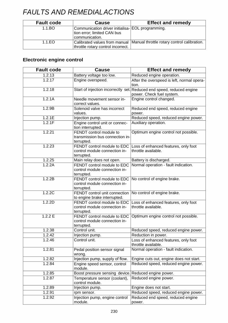
Fault code Cause Effect and remedy 1.1.BO Communication driver initialisa-
tion error; limited CAN bus communication.
EOL programming.
1.1.EO Calibrated values from manual throttle rotary control incorrect.
Manual throttle rotary control calibration.
Electronic engine control
Fault code Cause Effect and remedy 1.2.13 Battery voltage too low. Reduced engine operation.
1.2.17 Engine overspeed. After the overspeed is left, normal opera- tion.
1.2.18 Start of injection incorrectly set. Reduced end speed, reduced engine power. Check fuel system.
1.2.1A Needle movement sensor in- correct values.
Engine control changed.
1.2.9B Solenoid valve has incorrect values.
Reduced end speed, reduced engine power.
1.2.1E Injection pump. Reduced speed, reduced engine power.
1.2.1F Engine control unit or connec- tion interrupted.
Auxiliary operation.
1.2.21 FENDT control module to transmission bus connection in- terrupted.
Optimum engine control not possible.
1.2.23 FENDT control module to EDC control module connection in- terrupted.
Loss of enhanced features, only foot throttle available.
1.2.25 Main relay does not open. Battery is discharged.
1.2.2A FENDT control module to EDC control module connection in- terrupted.
Normal operation - fault indication.
1.2.2B FENDT control module to EDC control module connection in- terrupted.
No control of engine brake.
1.2.2C FENDT control unit connection to engine brake interrupted.
No control of engine brake.
1.2.2D FENDT control module to EDC control module connection in- terrupted.
Loss of enhanced features, only foot throttle available.
1.2.2 E FENDT control module to EDC control module connection in- terrupted.
Optimum engine control not possible.
1.2.38 Control unit. Reduced speed, reduced engine power.
1.2.42 Injection pump. Reduction in power.
1.2.46 Control unit. Loss of enhanced features, only foot throttle available.
1.2.81 Pedal position sensor signal wrong.
Normal operation - fault indication.
1.2.82 Injection pump, supply of flow. Engine cuts out, engine does not start.
1.2.84 Engine speed sensor, control module.
Reduced speed, reduced engine power.
1.2.85 Boost pressure sensing device. Reduced engine power.
1.2.87 Temperature sensor (coolant), control module.
Reduced engine power.
1.2.89 Injection pump. Engine does not start.
1.2.91 rpm sensor. Reduced speed, reduced engine power.
1.2.92 Injection pump, engine control module.
Reduced end speed, reduced engine power.

231
FAULTS AND REMEDIAL ACTIONS
Fault code Cause Effect and remedy 1.2.96 Control unit. Engine cuts out.
1.2.99 Control unit to injection pump connection is interrupted.
Reduced speed, reduced engine power.
1.2.A2 Engine control unit or injection pump.
Reduced speed, reduced engine power.
1.2A6 Engine control unit or injection pump.
Reduced speed, reduced engine power.
1.2.A8 Engine control unit has wrong value.
Normal operation - fault indication.
1.2.A9 Injection pump. Reduced end speed, reduced engine power.
1.2.B1 Control unit to injection pump connection is interrupted.
Reduced speed, reduced engine power.
1.2.B2 Control unit, injection pump. Reduced speed, reduced engine power.
1.2.B3 Interrupted power supply. Engine stops, engine does not start.
1.2.B4 Control unit to injection pump connection is interrupted.
Loss of enhanced features, only foot throttle available.
1.2.B5 Control unit, injection pump. Reduced speed, reduced engine power.
1.2.B6 Control unit, injection pump. Reduced speed, reduced engine power.
1.2.B7 Engine speed sensor. Reduced speed, reduced engine power.
1.2.B9 Control unit, injection pump. Engine stops.
1.2.C1 Pump control unit faulty. Engine goes into idle.
1.2.C3 EDC control module - pump controller connection interrup- ted.
Engine goes into idle.
1.2.C4 Injection pump. Engine goes into idle.
1.2.C5 Stop solenoid valve. Reduced speed, reduced engine power.
1.2.C7 Injection pump, fuel lines faulty. Engine stops. Check fuel system.
1.2.C8 Control unit, needle movement sensor, boost pressure sensor.
Engine stops.
1.2.C9 Injection pump. Normal operation - fault indication.
1.2.CA Injection timing mechanism va- lues not within tolerance.
Reduced rpm, reduced engine power. Check fuel system.
1.2CB Control unit to injection pump connection is interrupted.
Loss of enhanced features, only foot throttle available.
1.2.CD Injection pump. Reduced speed, reduced engine power.
1.2.DE Control unit. Loss of enhanced features, only foot throttle available.
1.2.EO EDC control unit not connec- ted.
Normal operation - fault indication.
1.2.E1 PTO rpm or speed signal incor- rect.
Normal operation - fault indication.
Implement control
Fault code Cause Effect and remedy 2.1.EO CAN communication E-Box -
CAN joystick defective. Implements can no longer be controlled using the joystick.
2.1.EE LBS job computer inoperative. Check CAN bus system for implement control.
2.1.EF Error message from mounted implement.
Refer to implement manufacturer's ma- nual.

232
FAULTS AND REMEDIAL ACTIONS
Operating console
Fault code Cause Effect and remedy 3.1.01
3.1.02
3.1.03
3.1.04 Programming error. Call workshop.
3.1.05
3.1.06
Transmission
Fault code Cause Effect and remedy 4.1.01 Joystick acceleration switch
I-IV faulty. Auxiliary operation.
4.1.04 Clutch pedal potentiometer faulty.
No monitoring of transmission ratios.
4.1.05 Pressure sensor II defective. Reduced comfort.
4.1.06 Accelerator rotary control faulty. Load limit control not functioning.
4.1.07 High-pressure sensor faulty. Peak loads in the transmission are no longer monitored.
4.1.08 Operating range I/II analogue device (function angle device) faulty.
Operating range switching I/II not opera- tional.
4.1.20 Accelerator cancellation rotary control incorrectly calibrated or not calibrated.
Accelerator mode not working.
4.1.21 Reverse mode switch is defec- tive.
Reverse mode operation and accelerator mode no longer possible.
4.1.22 Accelerator cancellation rotary control faulty.
Restriction in operation of accelerator mode.
4.1.23 Joystick signal Tempomat on faulty.
Auxiliary operation.
4.1.24 Hand brake switch faulty. Hand brake automatic mode not working.
4.1.25 Joystick F-R quick reverse si- gnal faulty.
Auxiliary operation.
4.1.26 Joystick signal accelerator mode faulty.
Accelerator mode not working.
4.1.27 Armrest signal rapid reversal (F/R rocker) faulty.
Rapid reverse not working.
4.1.28 Track width adjustment faulty. Auxiliary operation.
4.1.29 Joystick park position signal faulty.
Auxiliary operation.
4.1.2A Bevel pinion rpm sensor direc- tion signal faulty.
Auxiliary operation.
4.1.2B Driving mode I/II selection but- ton faulty.
Tractor remains in current dricing mode. No further selection until ignition ON/ OFF.
4.1.2C 'Neutral selection' button faulty. Auxiliary operation.
4.1.2D Quick Reverse button (steering column) faulty.
Quick Reverse only available with the joystick.
4.1.2E Joystick key 'v+' faulty. Auxiliary operation.
4.1.2F Joystick v- faulty. Auxiliary operation.
4.1.31 Direction signal speed sensor for hydrostatic unit faulty.
Auxiliary operation.
4.1.32 Joystick activating button faulty. Auxiliary operation.
4.1.42 Speed sensor hydrostatic unit faulty.
Auxiliary operation.

233
FAULTS AND REMEDIAL ACTIONS
Fault code Cause Effect and remedy 4.1.44 Speed sensor engine 1 faulty. Auxiliary operation.
4.1.45 Bevel pinion speed sensor faulty.
Auxiliary operation.
4.1.50 Transmission oil filter dirty. Auxiliary operation.
4.1.53 Transmission oil temperature over 110.
Damage to traction drive.
4.1.58 Slip values of transmission ra- tios beyond acceptable limits.
Occasional occurrences in extreme con- ditions have no effect. If the problem per- sists in normal conditions, contact the workshop immediately.
4.1.59 Emergency operation manually induced or by electrical activa- tion; emergency operation de- fective when operated non-ma- nually.
Fault code not in the memory.
4.1.61 Faulty activation of operating range I valve.
Auxiliary operation.
4.1.62 Faulty activation of operating range II valve.
Auxiliary operation.
4.1.63 Faulty activation of valve for mechanical speed limitation.
Max. speed 30 km/h only.
4.1.64 Faulty actuation of turboclutch valve.
Auxiliary operation.
4.1.65 Faulty activation of cardan brake.
Call workshop.
4.1.66 Faulty activation of cardan brake.
Call workshop.
4.1.67 Faulty activation of cardan brake.
Call workshop.
4.1.70 Tempomat cruise control 1 key faulty.
No Tempomat cruise control.
4.1.71 Tempomat cruise control 2 key faulty.
No Tempomat cruise control.
4.1.72 Filter contamination switch de- fective.
No monitoring of filter contamination.
4.1.73 Temperature output sensor faulty.
No temperature output monitoring.
4.1.74 Parking brake position recogni- tion switch faulty.
Hand brake position not detected, no hand brake automatic mode.
4.1.76 Engine brake switch faulty. No engine brake function.
4.1.77 Joystick acceleration rate I-IV faulty.
Operation only possible in acceleration rate III.
4.1.78 Starting cut-out seat switch for accelerator mode faulty.
Selection of direction of travel is always deactivated in accelerator mode when vehicle stationary for 3 seconds.
4.1.82 Plausibility error (engine speed) between hydrostatic unit speed sensor and bevel pi- nion speed sensor.
Auxiliary operation.
4.1.83 Plausibility error (direction) bet- ween hydrostatic unit speed sensor and bevel pinion speed sensor.
Auxiliary operation.
4.1.84 Plausibility error between the joystick controls (F/R, Tempo- mat cruise control).
Auxiliary operation.
4.1.85 Engine speed sensor I plausibi- lity error.
Auxiliary operation.

234
FAULTS AND REMEDIAL ACTIONS
Fault code Cause Effect and remedy 4.1.86 Plausibility error between pres-
sure sensor I and pressure sen- sor II.
Reduced comfort.
4.1.87 Plausibility error on F/R button on steering column.
No F/R function on steering column.
4.1.88 Plausibility error on ON/OFF button for accelerator pedal drive.
No function.
4.1.94 CAN communication E-Box and joystick faulty.
Joystick functions restricted. Call work- shop.
Transmission
Fault code Cause Effect and remedy 4.1.A0 Adjuster actuation faulty. Auxiliary operation.
4.1.A1 Control unit mechanical stop defective.
Auxiliary operation.
4.1.A2 Faulty CAN bus connection to control unit.
Auxiliary operation.
4.1.A3 Control unit incremental sensor faulty / not plausible.
Auxiliary operation.
4.1.A4 Adjuster EST track signal faul- ty/missing.
Auxiliary operation.
4.1.A5 Adjuster reference not found. Auxiliary operation.
4.1.A6 Incorrect control unit reference point during operation.
Auxiliary operation.
4.1.B0 Initialisation error on communi- cation driver. CAN bus commu- nication restricted.
Restricted operation.
4.1.B1 Fatal error range control with subsequent emergency opera- tion (e.g. valve fault).
Auxiliary operation.
4.1.B2 Transmission ratio limiting faulty.
EOL programming.
4.1.B3 Quick Reverse acceleration rate parameters out of tole- rance.
EOL programming.
4.1.B4 Engine speed sensor I plausibi- lity error.
EOL programming.
4.1.B5 Rapid reversing ramp parame- ter for Tractor Management Sy- stem (TMS) checksum error.
Rapid reversing not operational in the Tractor Management System (TMS).
4.1.EO Turboclutch characteristic faul- ty/incorrectly memorised.
EOL programming.
4.1.E1 Traction control pressure regu- lator parameter fault/read error.
EOL programming.
4.1.E2 Pressure regulator parameters in traction control are not plau- sible or read in incorrectly.
No traction control function.
4.1.E3 Accelerator checksum error. EOL programming.
4.1.E4 Brake control checksum error. EOL programming.
4.1.E9 Values of operating range shift II-I not within tolerance.
Only shift while at a standstill.
4.1.EA Incorrect EOL programming. Auxiliary operation.
4.1.EB Range-change values out of to- lerance or range-change not calibrated.
Auxiliary operation.

235
FAULTS AND REMEDIAL ACTIONS
Fault code Cause Effect and remedy 4.1.EC Accelerator rotary control va-
lues not within tolerances or no calibration of accelerator rotary control.
Auxiliary operation.
4.1.ED Clutch pedal potentiometer va- lues out of tolerance or clutch not calibrated.
Auxiliary operation.
4.1.EE Transmission characteristic va- lues out of tolerance or no cali- bration of transmission.
Auxiliary operation.
4.1.EF Turboclutch values out of tole- rance or no calibration.
Auxiliary operation.
4.1.FF Error in transmission EST con- trol unit.
Auxiliary operation.
Four-wheel drive and differential lock
Fault code Cause Effect and remedy 5.1.31 100% 4-WD button faulty. '4-WD automatic mode' available only.
5.1.32 Key for automatic 4WD faulty. '100% 4-WD' available only.
5.1.33 Faulty 4-WD clutch solenoid valve.
Function terminated, 4-WD engages.
5.1.34 Steering angle sensor 1 faulty. 4-WD / differential lock automatic mode Stop not functioning.
5.1.35 Steering angle sensor 2 faulty. 4-WD / differential lock automatic mode Stop not functioning.
5.1.51 100% differential lock button faulty.
Only 'Differential lock automatic mode' function available.
5.1.52 Key for automatic differential lock faulty.
'100% differential lock' is only function still available.
5.1.53 Differential lock solenoid actua- tion faulty.
End of function, differential lock not dis- engaging.
5.1.54 Left brake pedal switch faulty. '100% differential lock' is only function still available.
5.1.55 Right brake pedal switch faulty. '100% differential lock' is only function still available.
Suspension
Fault code Cause Effect and remedy 5.1.61 Front axle suspension position
sensor faulty. Front axle suspension does not function. Possible to continue without suspension.
5.1.62 Front axle suspension "Raise" solenoid actuation faulty.
Front axle suspension does not function. Possible to continue without suspension.
5.1.63 Incorrect activation of solenoid valve 'lower'for front axle sus- pension.
Front axle suspension does not function. Possible to continue without suspension.
5.1.64 Front axle suspension on/off key defective.
Front axle suspension does not function. Possible to continue without suspension.
5.1.65 Lock front axle suspension key faulty.
Locking of front axle suspension no lon- ger possible.
5.1.6 E No calibration of position sen- sor.
Front axle suspension does not function. Readjust position sensor.

236
FAULTS AND REMEDIAL ACTIONS
Power lift and PTO automatic mode
Fault code Cause Effect and remedy 5.1.91 Joystick rear automatic mode
on/off button faulty. Rear automatic mode not working.
5.1.93 Joystick front automatic mode on/off button faulty.
Front automatic mode not functioning.
5.1.95 Joystick automatic mode stop button faulty.
Automatic mode cannot be switched on and off.
Hydraulic system (push button / flow controller)
Fault code Cause Effect and remedy 5.1.98 Control pump oil pressure mo-
nitoring faulty. Possible failure of work hydraulics.
5.1.99 Signal of flow control sensor disturbed or no oil pressure on the auxiliary pump.
Possible failure of auxiliary pump (con- stant displacement pump).
Other fault codes
Fault code Cause Effect and remedy 5.1.00 Control unit fault. E-Box faulty.
5.1.8D Checksum error. Old automatic mode configuration data.
Reduced comfort.
5.1.8F Checksum error. Old automatic function sequential data.
Reduced comfort.
5.1.9A Plausibility check error on flow controller with ignition ON and engine OFF.
No pressure monitoring.
5.1.9B 8 bar pressure switch faulty. No pressure monitoring.
5.1.B0 Initialisation error on communi- cation driver. CAN bus commu- nication restricted.
EOL programming.
5.1.9E Engine coolant level too low or empty.
Risk of engine damage. Once the war- ning has been confirmed, the error mes- sage is output every 120 sec. if the coo- lant has not be topped up.
5.1.9F Engine coolant level sensor de- fective.
No coolant level monitoring.
5.1.FF Comfort E-box no longer recei- ving CAN data for engine speed and PTO speed.
Various indicators no longer available or comfort E-box fails completely.
Rear PTO
Fault code Cause Effect and remedy 6.1.01 Button in cab faulty. Does not function, PTO disengages.
6.1.02 Key on right mudguard faulty. PTO can only be switched on/off with the cab button. Button must be pressed for at least 5 secs.
6.1.03 Button on left mudguard faulty. PTO can only be switched on/off with the cab button. Button must be pressed for at least 5 secs.
6.1.04 PTO shaft clutch solenoid valve faulty.
Does not function, PTO disengages.

237
FAULTS AND REMEDIAL ACTIONS
Fault code Cause Effect and remedy 6.1.05 PTO shaft rpm sensor faulty. PTO can only be switched on/off with the
cab button. Button must be pressed for at least 5 secs.
6.1.10 Speed sensor shaft faulty.
6.1.11 Automatic mode on operating console faulty.
Automatic mode is ended and PTO dis- engages.
6.1.15 Neutral speed selection key faulty.
Does not function, PTO disengages.
6.1.16 Selection range key 540 faulty. No function of range selection key 540.
6.1.17 Setting 540E selection button faulty.
Setting 540E selection button does not function.
6.1.18 Speed selection key 1000 faulty.
No function of speed selection key 1000.
6.1.1A Setting 540 valve faulty. Does not function, PTO disengages.
6.1.1B Control valve 540E faulty. Does not function, PTO disengages.
6.1.1C Control valve 1000 faulty. Does not function, PTO disengages.
6.1.41 Cab button plausibility error. Does not function, PTO disengages.
6.1.42 Right mudguard button plausi- bility error.
Does not function, PTO disengages.
6.1.43 Left mudguard button plausibi- lity error.
Does not function, PTO disengages.
6.1.45 PTO clutch rpm sensor plausi- bility error.
PTO can only be operated via keys inside the cab, key must be kept pressed for at least 5 secs.
6.1.50 Speed sensor PTO shaft plau- sibility error.
When engaging, the button must be pres- sed for at least 5 secs.
6.1.55 Plausibility error in speed se- lection key neutral.
Does not function, PTO disengages.
6.1.56 Plausibility error in speed se- lector key 540.
No function of 540 selection.
6.1.57 540E setting pre-selection but- ton plausibility error.
No function of 540E selection.
6.1.58 Plausibility error in speed se- lection key 1000.
No function of 1000 selection.
6.1.60 Plausibility error between PTO clutch rpm and PTO stub shaft speed.
Does not function, PTO disengages.
6.1.BO Initialisation error on communi- cation driver. CAN bus commu- nication restricted.
EOL programming.
6.1.C1 Switch-on speed not reached for PTO/power lift automatic mode.
Increase ground speed to more than 1 km/h.
6.1.EO Checksum parameter current control for range shifting faulty.
EOL programming.
6.1.E1 Checksum PTO parameter faulty.
EOL programming.

238
FAULTS AND REMEDIAL ACTIONS
Front PTO
Fault code Cause Effect and remedy 7.1.01 PTO key inside the cab faulty. Does not function, PTO disengages.
7.1.04 Clutch operation solenoid faulty.
7.1.05 PTO shaft rpm sensor faulty. To engage, the button must be pressed for at least 5 sec.
7.1.09 Automatic front PTO key on operating console defective.
Automatic mode is ended and PTO dis- engages.
7.1.41 Cab button plausibility error. Does not function, PTO disengages.
7.1.C1 Switch-on speed not reached for PTO/power lift automatic mode.
Increase ground speed to more than 1 km/h.
EPC-C rear power lift
Fault code Cause Effect and remedy 8.3.11 Lift final stage defective. Control is terminated and locked.
8.3.12 Lower final stage defective. Control is terminated and locked.
8.3.14 Rear left 'Lift'key is defective. Control is terminated and locked.
8.3.15 Left rear "Lower" button faulty. Control is terminated and locked.
8.3.16 V regulator less than 1 Volt. Control is terminated and locked.
8.3.17 Battery voltage over 18 V. Control is terminated and locked.
8.3.18 Rear right 'Lift' key is defective. Control is terminated and locked.
8.3.19 Rear right 'Lower' key is defec- tive.
Control is terminated and locked.
8.3.22 Position sensor defective. Control is terminated and locked.
8.3.23 Setpoint rotary control defec- tive.
Control is terminated and locked.
8.3.26 Faulty external sensor. Control is terminated and locked.
8.3.31 Right draught sensing pin de- fective.
Control is continued
8.3.32 Left load sensor pin faulty. Control is continued
8.3.33 Battery voltage less than 10.5 V.
Control is continued
8.3.40 Quick Lift switch faulty. Raise and Lower only possible with the rear controls.
8.3.41 Fast feed-in button faulty. Fast feed-in does not function.
8.3.42 Hitch button faulty. Hitch key not functioning.
8.3.43 Automatic rear lifting gear key (control console) defective.
Automatic rear lifting gear key not opera- tional.
8.3.50 Warning, right load sensor pin overloaded.
Warning is not stored. Relieve drafting sensing pin of load.
8.3.51 Warning, left load sensor pin overloaded.
Warning is not stored. Relieve drafting sensing pin of load.
Front power lift
Fault code Cause Effect and remedy 9.1.50 Valve not registered on CAN-
bus. Valve actuation not possible.
9.1.5F Incorrect messages sent on CAN bus. Electronics in valve faulty.
Valve goes into neutral position.
9.1.51 Electronics in valve faulty. Valve goes into neutral position. Replace valve.
239
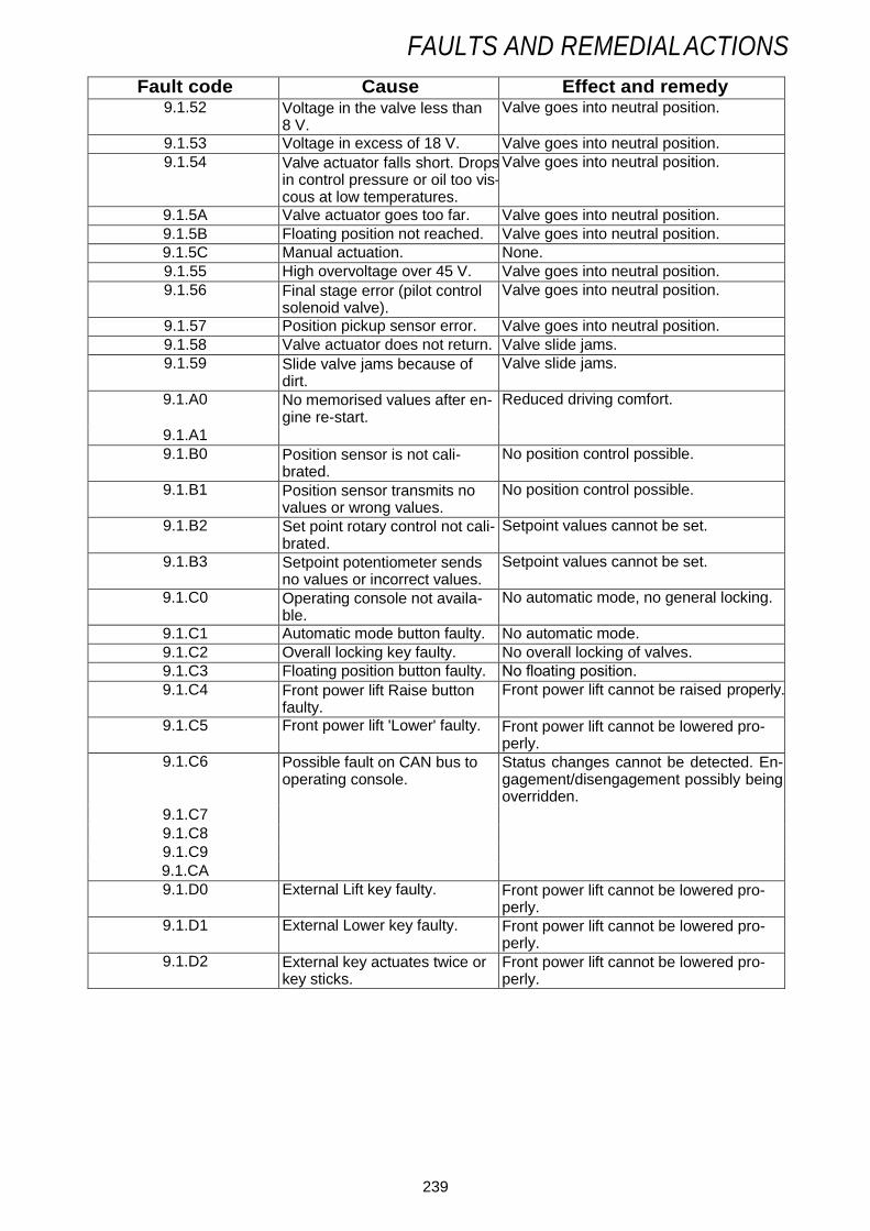
FAULTS AND REMEDIAL ACTIONS
Fault code Cause Effect and remedy 9.1.52 Voltage in the valve less than
8 V. Valve goes into neutral position.
9.1.53 Voltage in excess of 18 V. Valve goes into neutral position.
9.1.54 Valve actuator falls short. Drops in control pressure or oil too vis- cous at low temperatures.
Valve goes into neutral position.
9.1.5A Valve actuator goes too far. Valve goes into neutral position.
9.1.5B Floating position not reached. Valve goes into neutral position.
9.1.5C Manual actuation. None.
9.1.55 High overvoltage over 45 V. Valve goes into neutral position.
9.1.56 Final stage error (pilot control solenoid valve).
Valve goes into neutral position.
9.1.57 Position pickup sensor error. Valve goes into neutral position.
9.1.58 Valve actuator does not return. Valve slide jams.
9.1.59 Slide valve jams because of dirt.
Valve slide jams.
9.1.A0 No memorised values after en- gine re-start.
Reduced driving comfort.
9.1.A1
9.1.B0 Position sensor is not cali- brated.
No position control possible.
9.1.B1 Position sensor transmits no values or wrong values.
No position control possible.
9.1.B2 Set point rotary control not cali- brated.
Setpoint values cannot be set.
9.1.B3 Setpoint potentiometer sends no values or incorrect values.
Setpoint values cannot be set.
9.1.C0 Operating console not availa- ble.
No automatic mode, no general locking.
9.1.C1 Automatic mode button faulty. No automatic mode.
9.1.C2 Overall locking key faulty. No overall locking of valves.
9.1.C3 Floating position button faulty. No floating position.
9.1.C4 Front power lift Raise button faulty.
Front power lift cannot be raised properly.
9.1.C5 Front power lift 'Lower' faulty. Front power lift cannot be lowered pro- perly.
9.1.C6 Possible fault on CAN bus to operating console.
Status changes cannot be detected. En- gagement/disengagement possibly being overridden.
9.1.C7
9.1.C8
9.1.C9
9.1.CA
9.1.D0 External Lift key faulty. Front power lift cannot be lowered pro- perly.
9.1.D1 External Lower key faulty. Front power lift cannot be lowered pro- perly.
9.1.D2 External key actuates twice or key sticks.
Front power lift cannot be lowered pro- perly.

240
FAULTS AND REMEDIAL ACTIONS
Electric valves (oeprating console)
Fault code Cause Effect and remedy A.1.C0 Control console not available,
e.g. CAN-bus not connected. No automatic mode. No general locking of valves.
A.1.C1 Automatic mode button faulty. No automatic mode.
A.1.C2 Overall locking key faulty. No overall locking of valves.
A.1.C3 Floating position button faulty. No floating position.
A.1.C4 Timer function button faulty. No timer function.
A.1.C5 Crossgate lever/joystick swit- chover button faulty.
Not possible to switch between crossgate lever operation and joystick operation.
A.1.C6 Operating console CAN bus faulty.
Change of status not detected. Switching on/off is ignored. Valve locked.
A 1.C7
A.1.C8
A.1.C9
A.1.CA
A.1.CB CAN joystick not available. Not possible to operate valves.
A.1.CC E-Box and CAN joystick CAN connection faulty.
Limited operation of valves.
Electric valves (crossgate lever)
Fault code Cause Effect and remedy A.1.B0 Crossgate lever not adjusted. Valves cannot be actuated. Carry out ad-
justment. A.1.B1 Signal fault. Valve position cannot be controlled pro-
perly. A.1.B2
A.1.B3
A.1.B4
A.1.B5 Crossgate lever recognition of centre position faulty.
Valve position cannot be operated accu- rately. Calibrate.
Electric valves (buttons / switches)
Fault code Cause Effect and remedy A.1.FA External valve actuation. Spool
valve external pushbutton for rear LIFT faulty.
Rear external controls not working.
A.1.FB External valve actuation. Spool valve external pushbutton for rear LOWER faulty.
Rear external controls not working.
A.1.FC External valve actuation. Spool valve external pushbutton rear actuates twice or pushbutton is faulty.
Change controls or exchange keys.
A.1.D1 Valve 3, signal disturbed or faulty valve.
'Lift' and/or 'Lower' valve 3 faulty.
A.1.D3 Valve 4, signal disturbed or faulty valve.
'Lift' and/or 'Lower' valve 4 faulty.
A.1.D4 Faulty solenoid switch for re- lease of external controls of standard front power lift.
Position of shutoff cock for front power lift cannot be detected.
A.1.D5 External front power lift 'Lower' button faulty.
Front power lift cannot be lowered pro- perly.

[НАЗВАНИЕ ДОКУМЕНТА] МИХАИЛ ДОБРЫДЕНЬ
FAULTS AND REMEDIAL ACTIONS
Fault code Cause Effect and remedy A.1.D6 External front power lift 'Raise'
button faulty. Front power lift cannot be raised properly.
A.1.D7 Hydraulic oil level sensor faulty. Hydraulic oil level no longer monitored.
A.1.D9 Hydraulic tank is empty. Possible damage to pump or undesired valve responses.
A.1.DA Kickout push button faulty. No Kickout function.
A.1.DB Hydraulic oil characteristic not plausible.
Incorrect display of hydraulic oil supply. Reprogramme EOL.
A.1.DC Priority volume of hydraulic oil greater than pump volume.
Reduce priority hydraulic oil quantity.
A.1.DD Front external key actuates twice or key sticks.
Front power lift cannot be lowered pro- perly.
Electrical valves (valve 1)
Fault code Cause Effect and remedy A.1.10 Valve not registered on CAN
bus. Valve actuation not possible.
A.1.1F CAN-BUS error, valves. Valves locked.
A.1.11 Electronics in valve faulty. Valve goes into neutral position.
A.1.12 Voltage in the valve less than 8 Volt.
Valve goes into neutral position.
A.1.13 Voltage in excess of 18 V. Valve goes into neutral position.
A.1.14 Valve actuator falls short. Valve goes into neutral position.
A.1.1A Valve actuator goes too far. Valve goes into neutral position.
A.1.1B Floating position not reached. Valve goes into neutral position.
A.1.1C Manual actuation.
A.1.15 High overvoltage over 45 V. Valve goes into neutral position.
A.1.16 End stage error (end stage for pilot control solenoid).
Valve goes into neutral position.
A.1.17 Position pickup sensor error. Valve goes into neutral position.
A.1.18 Valve actuator does not return to neutral position.
Valve remains set.
A.1.19 Valve actuator not in neutral po- sition when switched on.
Valve remains set.

[НАЗВАНИЕ ДОКУМЕНТА] МИХАИЛ ДОБРЫДЕНЬ
FAULTS AND REMEDIAL ACTIONS
Spool valves (valve 2)
Fault code Cause Effect and remedy A.1.20 Valve not registered on CAN
bus. Valve actuation not possible.
A.1.2F CAN-BUS error, valves. Valves locked.
A.1.21 Electronics in valve faulty. Valve goes into neutral position.
A.1.22 Voltage in the valve less than 8 Volt.
Valve goes into neutral position.
A.1.23 Voltage in excess of 18 V. Valve goes into neutral position.
A.1.24 Valve actuator falls short. Valve goes into neutral position.
A.1.2A Valve actuator goes too far. Valve goes into neutral position.
A.1.2B Floating position not reached. Valve goes into neutral position.
A.1.2C Manual actuation.
A.1.25 High overvoltage over 45 V. Valve goes into neutral position.
A.1.26 End stage error (end stage for pilot control solenoid).
Valve goes into neutral position.
A.1.27 Position pickup sensor error. Valve goes into neutral position.
A.1.28 Valve actuator does not return to neutral position.
Valve remains set.
A.1.29 Valve actuator not in neutral po- sition when switched on.
Valve remains set.
Spool valves (valve 3)
Fault code Cause Effect and remedy A.1.30 Valve not registered on CAN
bus. Valve actuation not possible.
A.1.3F Valve CAN BUS error. Valves locked.
A.1.31 Electronics in valve faulty. Valve goes into neutral position.
A.1.32 Voltage in the valve less than 8 Volt.
Valve goes into neutral position.
A.1.33 Voltage in excess of 18 V. Valve goes into neutral position.
A.1.34 Valve actuator falls short. Valve goes into neutral position.
A.1.3A Valve actuator goes too far. Valve goes into neutral position.
A.1.3B Floating position not reached. Valve goes into neutral position.
A.1.3C Manual actuation.
A.1.35 High overvoltage over 45 V. Valve goes into neutral position.
A.1.36 End stage error (end stage for pilot control solenoid).
Valve goes into neutral position.
A.1.37 Position pickup sensor error. Valve goes into neutral position.
A.1.38 Valve actuator does not return to neutral position.
Valve remains set.
A.1.39 Valve actuator not in neutral po- sition when switched on.
Valve remains set.

[НАЗВАНИЕ ДОКУМЕНТА] МИХАИЛ ДОБРЫДЕНЬ
FAULTS AND REMEDIAL ACTIONS
Spool valves (valve 4)
Fault code Cause Effect and remedy A.1.40 Valve not registered on the
CAN bus. Valve actuation not possible.
A.1.4F CAN-BUS error, valves. Valves locked.
A.1.41 Electronics in valve faulty. Valve goes into neutral position.
A.1.42 Voltage in the valve less than 8 Volt.
Valve goes into neutral position.
A.1.43 Voltage in excess of 18 V. Valve goes into neutral position.
A.1.44 Valve actuator falls short. Valve goes into neutral position.
A.1.4A Valve actuator goes too far. Valve goes into neutral position.
A.1.4B Floating position not reached. Valve goes into neutral position.
A.1.4C Manual actuation.
A.1.45 High overvoltage over 45 V. Valve goes into neutral position.
A.1.46 End stage error (end stage for pilot control solenoid).
Valve goes into neutral position.
A.1.47 Position pickup sensor error. Valve goes into neutral position.
A.1.48 Valve actuator does not return to neutral position.
Valve remains set.
A.1.49 Valve actuator not in neutral po- sition when switched on.
Valve remains set.
Electric valves (E-box)
Fault code Cause Effect and remedy A.1.A0 EEPROM error. Loss of enhanced features when opera-
ting valves. A.1.A1
A.1.A2 More valves connected than are registered through end-of- line programming. Undertake programming.
Not all valves can be operated.
A.1.FO Valve control for the switching of the pilot control of all electri- cal valves with front power lift faulty.
All valves go into neutral position.
A.1.F1 Valve control for the heating of all electrical valves with front power lift faulty.
Reduced operation in cold conditions.
A.1.F2 Valve control for switching the pilot control of all spool valves with front power lift faulty.
Call workshop.
A.1.F3 Valve control for switching the pilot control of all spool valves with front power lift has inter- rupted supply line.
Call workshop.
Download from: https://truckmanualshub.com/
FAULTS AND REMEDIAL ACTIONS
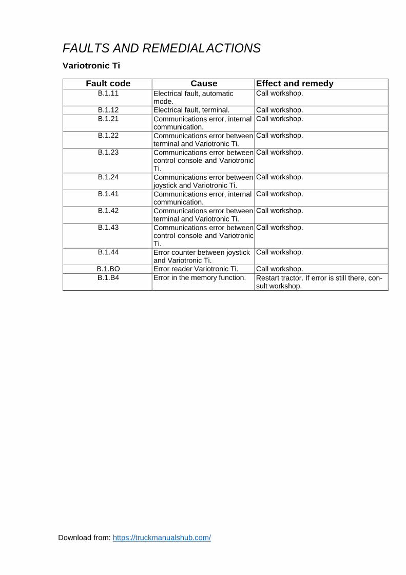
Variotronic Ti
Fault code Cause Effect and remedy B.1.11 Electrical fault, automatic
mode. Call workshop.
B.1.12 Electrical fault, terminal. Call workshop.
B.1.21 Communications error, internal communication.
Call workshop.
B.1.22 Communications error between terminal and Variotronic Ti.
Call workshop.
B.1.23 Communications error between control console and Variotronic Ti.
Call workshop.
B.1.24 Communications error between joystick and Variotronic Ti.
Call workshop.
B.1.41 Communications error, internal communication.
Call workshop.
B.1.42 Communications error between terminal and Variotronic Ti.
Call workshop.
B.1.43 Communications error between control console and Variotronic Ti.
Call workshop.
B.1.44 Error counter between joystick and Variotronic Ti.
Call workshop.
B.1.BO Error reader Variotronic Ti. Call workshop.
B.1.B4 Error in the memory function. Restart tractor. If error is still there, con- sult workshop.