Fatigue Fracture in Dual Modular Revision Total Hip Arthroplasty Stems
6
Fatigue Fracture in Dual Modular Revision Total Hip Arthroplasty Stems Failure Analysis and Computed Tomography Diagnostics in Two Cases Pontus Norman, MD a , Srinivasan Iyengar, MSc Eng, PhD b , Ingrid Svensson, MSc Eng, PhD c , Gunnar Flivik, MD, PhD a a Department of Orthopaedics, Skane University Hospital, Clinical Sciences, Lund University, Lund, Sweden b Division of Materials Engineering, Lund University, Lund, Sweden c Division of Solid Mechanics, Lund University, Lund, Sweden abstract article info Article history: Received 1 May 2013 Accepted 9 September 2013 Keywords: modular hip prosthesis fatigue failure CT We report on two patients with fracture of a modular, tapered and distally fixed, uncemented titanium revision hip stem, not previously described. A failure analysis revealed that the cause of the fractures was the development of fatigue cracks in the mid-stem cobalt–chromium modular junction ending in corrosion- fatigue failure. No material defects or stress risers were found in any of the implants. The diameter of the mid- stem modular junction might be undersized for use in heavy and active patients. We also report a new way of detecting an undisplaced fracture at the modular junction, using the scout image from a computed tomography (CT) scan; a technique that can be used when plain radiographs are inconclusive. © 2014 Elsevier Inc. All rights reserved. Fracture of the femoral stem is a well known, but infrequent complication of Total Hip Arthroplasty (THA). A consistently low fracture incidence (0.23%–0.27%) has been found over the years [1,2], and many improvements, including the use of cobalt–chromium– molybdenum (CoCrMo) or titanium alloys, have helped reduce the incidence of prosthetic fracture in modern stem designs [3–5]. In revision THA, modular femoral stems are increasingly popular, and stems with more than one modular junction are frequently used. Modularity makes it easier for the surgeon to restore the patient's anatomy by optimizing leg length, version and offset intraoperatively [6–10]. There have also been reports of improvement in the quality of life for patients who receive modular revision stems in comparison with non-modular ones [9,11]. There are however reports indicating that modularity increases the complication rate and might make the implants susceptible to corrosion, fretting and fatigue fracture at the modular junctions [8– 10,12,13]. In 2010, a large study of hip prostheses with modular neck adapters reported a failure rate of 1.4% [12]. Recently concern has been raised regarding high blood levels of cobalt due to metal ion release from corrosion at the metal-on-metal taper connections in patients with dual modular cobalt–chrome hip prostheses [14]. In the light of this, the safety in using modular prostheses has become a subject for discussion. Revitan (Zimmer GmbH, Winterthur, Switzerland) is a dual modular, tapered and distally fixed, uncemented femoral stem manufactured from titanium niobium alloy (TiAl6Nb7). It has a mid- stem modular junction in which the proximal and distal components are joined together by a dual tapered cylinder, made of a cobalt alloy (CoCrMo) to offer high mechanical resistance. Revitan is a develop- ment of the PFM-R stem (Zimmer GmbH, Winterthur, Switzerland) which has been successfully used for almost 20 years. To this date, there are very few publications available about Revitan prostheses, but one study from 2009 shows good results after a minimum of 24 months of follow-up of the Revitan curved stems [15]. Fractures of other dual modular, cementless stems have been reported in the literature [6,8,11,16,17], but to our knowledge no fracture of the Revitan stem has been reported. We are here reporting the fractures of two Revitan straight prostheses. The objectives of this study are to describe our experience with fracture in this stem design and to analyze the underlying cause by metallurgical examination and comparing our findings with the literature. We also report a new way to detect an undisplaced fracture at the modular junction of a femoral component, which is not obvious on plain radiographs. Materials and Methods Within one year, two patients presented at our department with fracture at the modular junction of a Revitan stem. The first patient was a still hard working 69 year old farmer, who had had the implant for 36 months at the time of fracture. The revision had been performed for late prosthetic infection in an already revised cemented The Journal of Arthroplasty 29 (2014) 850–855 The Conflict of Interest statement associated with this article can be found at http:// dx.doi.org/10.1016/j.arth.2013.09.008. Reprint requests: Department of Orthopaedics Skane University Hospital S-221 85 Lund Sweden. 0883-5403/2904-0044$36.00/0 – see front matter © 2014 Elsevier Inc. All rights reserved. http://dx.doi.org/10.1016/j.arth.2013.09.008 Contents lists available at ScienceDirect The Journal of Arthroplasty journal homepage: www.arthroplastyjournal.org
-
Upload
independent -
Category
Documents
-
view
1 -
download
0
Transcript of Fatigue Fracture in Dual Modular Revision Total Hip Arthroplasty Stems

The Journal of Arthroplasty 29 (2014) 850–855
Contents lists available at ScienceDirect
The Journal of Arthroplasty
j ourna l homepage: www.ar throp lasty journa l .o rg
Fatigue Fracture in Dual Modular Revision Total Hip Arthroplasty StemsFailure Analysis and Computed Tomography Diagnostics in Two Cases
Pontus Norman, MD a, Srinivasan Iyengar, MSc Eng, PhD b, Ingrid Svensson, MSc Eng, PhD c,Gunnar Flivik, MD, PhD a
a Department of Orthopaedics, Skane University Hospital, Clinical Sciences, Lund University, Lund, Swedenb Division of Materials Engineering, Lund University, Lund, Swedenc Division of Solid Mechanics, Lund University, Lund, Sweden
a b s t r a c ta r t i c l e i n f o
The Conflict of Interest statement associated with thdx.doi.org/10.1016/j.arth.2013.09.008.
Reprint requests: Department of Orthopaedics SkanLund Sweden.
0883-5403/2904-0044$36.00/0 – see front matter © 20http://dx.doi.org/10.1016/j.arth.2013.09.008
Article history:Received 1 May 2013Accepted 9 September 2013
Keywords:modularhip prosthesisfatigue failureCT
We report on two patients with fracture of a modular, tapered and distally fixed, uncemented titaniumrevision hip stem, not previously described. A failure analysis revealed that the cause of the fractures was thedevelopment of fatigue cracks in the mid-stem cobalt–chromium modular junction ending in corrosion-fatigue failure. No material defects or stress risers were found in any of the implants. The diameter of the mid-stemmodular junction might be undersized for use in heavy and active patients. We also report a new way ofdetecting an undisplaced fracture at the modular junction, using the scout image from a computedtomography (CT) scan; a technique that can be used when plain radiographs are inconclusive.
is article can be found at http://
e University Hospital S-221 85
14 Elsevier Inc. All rights reserved.
© 2014 Elsevier Inc. All rights reserved.
Fracture of the femoral stem is a well known, but infrequentcomplication of Total Hip Arthroplasty (THA). A consistently lowfracture incidence (0.23%–0.27%) has been found over the years [1,2],and many improvements, including the use of cobalt–chromium–
molybdenum (CoCrMo) or titanium alloys, have helped reduce theincidence of prosthetic fracture in modern stem designs [3–5].
In revision THA, modular femoral stems are increasingly popular,and stems with more than one modular junction are frequently used.Modularity makes it easier for the surgeon to restore the patient'sanatomy by optimizing leg length, version and offset intraoperatively[6–10]. There have also been reports of improvement in the quality oflife for patients who receive modular revision stems in comparisonwith non-modular ones [9,11].
There are however reports indicating that modularity increasesthe complication rate and might make the implants susceptible tocorrosion, fretting and fatigue fracture at the modular junctions [8–10,12,13]. In 2010, a large study of hip prostheses with modular neckadapters reported a failure rate of 1.4% [12]. Recently concern hasbeen raised regarding high blood levels of cobalt due to metal ionrelease from corrosion at the metal-on-metal taper connections inpatients with dual modular cobalt–chrome hip prostheses [14]. In thelight of this, the safety in using modular prostheses has become asubject for discussion.
Revitan (Zimmer GmbH, Winterthur, Switzerland) is a dualmodular, tapered and distally fixed, uncemented femoral stemmanufactured from titanium niobium alloy (TiAl6Nb7). It has a mid-stem modular junction in which the proximal and distal componentsare joined together by a dual tapered cylinder, made of a cobalt alloy(CoCrMo) to offer high mechanical resistance. Revitan is a develop-ment of the PFM-R stem (Zimmer GmbH, Winterthur, Switzerland)which has been successfully used for almost 20 years. To this date,there are very few publications available about Revitan prostheses,but one study from 2009 shows good results after a minimum of24 months of follow-up of the Revitan curved stems [15]. Fractures ofother dual modular, cementless stems have been reported in theliterature [6,8,11,16,17], but to our knowledge no fracture of theRevitan stem has been reported.
We are here reporting the fractures of two Revitan straightprostheses. The objectives of this study are to describe our experiencewith fracture in this stem design and to analyze the underlying causeby metallurgical examination and comparing our findings with theliterature. We also report a newway to detect an undisplaced fractureat the modular junction of a femoral component, which is not obviouson plain radiographs.
Materials and Methods
Within one year, two patients presented at our department withfracture at the modular junction of a Revitan stem. The first patientwas a still hard working 69 year old farmer, who had had the implantfor 36 months at the time of fracture. The revision had beenperformed for late prosthetic infection in an already revised cemented

Table 1Patient Data.
PatientAgea
(Years) GenderWeighta
(kg)BMIa
(kg/m2)Reason for
Previous RevisionNumber ofRevisionsb
ETOc Used DuringLast Revision Proximal Component Distal Component
Time to fracture(months)
1 69 Male 117 31.4 Prosthetic Infection 2 Yes Cylindrical (55 mm) Straight (200 mm) 362 70 Male 95 29.0 Aseptic Loosening 1 Yes Cylindrical (65 mm) Straight (140 mm) 89
a At the time of fracture.b Total number of revisions prior to the prosthetic fracture.c Extended Trochanteric Osteotomy.
851P. Norman et al. / The Journal of Arthroplasty 29 (2014) 850–855
THA. Despite a rather long recovery period, the patient seemed to healwell, and he was completely asymptomatic for two years prior to thestem fracture. The second patient was a 70 year old, still very activebuilding inspector who had functioned well with the implant for89 months at the time of fracture. The revision had been performedfor aseptic loosening of a cemented THA. Clinical data on the patientsare presented in Table 1.
Radiography
The first patient presented with sudden onset of pain and inabilityto put weight on his leg. The fracture was obvious on plainradiographs as it was displaced, and this case did not present adiagnostic challenge. The second patient however had an atypicalpresentation with slowly increasing pain and walking difficulties overa period of a few weeks, until he had to use two crutches. Prostheticfracture did not seem the most likely cause. Plain radiographs showedno obvious fracture, signs of loosening or other complication (Fig 1).Computed tomography (CT) was performed with 1 mm slices, withand without metal artefact reduction technique.
Fig. 1. Anteroposterior radiograph in case 2, initially described as showing no signs ofprosthetic fracture.
Failure Analysis
The fractured stems from both patients were analyzed at theDivision of Materials Engineering at Lund University, Sweden. Theproximal part of the fractured connection was removed and cleanedultrasonically in ethanol. The cleaned proximal fracture surfaces wereexamined and photographed in a stereo microscope (Leica Model DFC320, Leica, Wetzlar, Germany) and an environmental scanningelectron microscope (Philips Model XL-30 ESEM, Philips/FEI, Eindho-ven, The Netherlands). Energy dispersive spectroscopy and X-raymapping (EDAX Phoenix System, EDAX, Tilburg, The Netherlands)were performed on the fracture surfaces for qualitative andquantitative information on the chemical components of the material.
The distal parts of the fractured connections were removed andsectioned vertically, to acquire cross sections perpendicular to thefracture surfaces. The exterior, rounded surfaces of the samples werepolished so that the sample had two parallel flat surfaces. KnoopMicrohardness tests were performed on the samples with a rhombic-based diamond pyramid indenter. The procedure recommended inthe ASTM standard E384 was followed. A load of ten grams and adwell time of ten seconds were used for the measurement.
Fig. 2. The mid-stem modular junction of the reference, unfractured Revitan prosthesisafter vertical sectioning. On the left is the CoCrMo cylinder connecting the proximaand distal components. In the middle, the surrounding proximal and distacomponents (with the CoCrMo cylinder removed). The distal component is fixed tothe CoCrMo cylinder during the manufacturing, while the proximal component isattached intraoperatively. The arrow shows the level at which the fractures occurredin both cases.
ll

Fig. 3. Coronal reconstruction of the CT images in case 2, showing no signs ofprosthetic fracture.
Fig. 4. The CT Scout image in case 2 (cropped), clearly showing the prosthetic fracture.
Fig. 5. Macroscopic appearance of the fractured prostheses in case 1 (right) and case 2(left). The proximal fracture surfaces are visible in the proximal components, while thedistal fracture surfaces are located inside the distal components.
852 P. Norman et al. / The Journal of Arthroplasty 29 (2014) 850–855
Microhardness values were determined at five spots on the surface,starting at the distal edge of the sample and ending close to thefracture area.
The remaining cross sections were polished and etched with a 6:1solution of HCl and H2O2. The etched surfaces were studied in ascanning electron microscope and the images of the alloy microstruc-ture in both samples were recorded.
As a reference for comparing the microstructure and microhard-ness, an unfractured Revitan stem that had been revised due toprosthetic infection after five years, was used. This prosthesis wassectioned vertically to visualize the structure of the mid-stemmodular junction, where the fractures had occurred in our patients(Fig 2). Sample preparation methods used for this prosthesis weresimilar to those described earlier and the sample surfaces wereexamined to reveal the microstructures as well as possible variationsin microhardness values along the surface.
Results
The CT images, 1 mm slices andmultiplanar reconstructions, takenin case 2 were examined by a skeletal radiologist, but no signs of aprosthetic fracture, or any obvious signs of osteolysis and looseningaround the stem were found (Fig 3). However, a non-helical, frontaloverview image is performed first in all CT scans to define areas ofinterest and plan the examination. This image, called a "Scout" or"Scanogram", is included in the images from the scan, and in thisimage an undisplaced fracture in the prosthetic modular junction wasclearly visible (Fig 4).
Failure Analysis
The fractures had in both cases occurred at the same location in theCoCrMo connection part, about 5 mm distal to the visible junction(Fig 5).
Stereomicroscopic examination of the superior fracture surfacesrevealed that the fractures were initiated in the lateral part andpropagated medially and proximally through the connection part. On
the lateral side the surface was rough, with signs of corrosion, andfrom this area concentric clamshell marks, characteristic of fatiguefailure were seen (Fig 6). The microscopic appearances of the fracturesurfaces were similar in both patients.

Fig. 6. Stereo microscopic image of the proximal fracture surface in case 1(magnification 20×). Notice the dark, corroded area (on the left) where the fracturewas initiated, and the concentric clamshell marks emerging from it.
Fig. 8. Scanning electron microscopic image from the polished and etched cross sectionof the CoCrMo connection part in case 1. The microstructure is characterized by smalgrains which show a variation in size between 3 and 15 μm. The carbide particles(white arrows) are present at the grain boundaries. Porosity is observed to be muchmore at the junction between grains than inside the grains. Pores are indicated withblack arrows.
853P. Norman et al. / The Journal of Arthroplasty 29 (2014) 850–855
Scanning electron microscopy performed at the fracture surfacesshowed extensive porosity, large pores and interconnecting cracks atthe grain borders in both cases. Dimples were found in the lateral partof the fracture surfaces, and carbide precipitates at the grain bordersand intergranular corrosion could be seen throughout the surfaces(Fig 7). Energy dispersive spectroscopy and X-raymapping showed anuneven distribution of the different components of the alloy, andareas without cobalt and chrome could be found in both cases, as istypical in the presence of intergranular corrosion. No signs of frettingor crevice corrosion were seen at the fracture surface.
Scanning electron microscopy of the cross sections from theCoCrMo connection parts revealed no major differences in themicrostructure between the two fractured prostheses and thereference sample. The average grain size was 5–10 μm in all threesamples. A small amount of porosity was evident in all samples, butslightly more apparent in the sample from case 2, and in all samplescarbide precipitations were found in almost every grain border. Nosigns of corrosion could be found in any sample (Fig 8).
The microhardness tests revealed no significant differencesbetween the two fractured prostheses and the reference sample.Mean microhardness was 439 KHN in case 1 (range 374–523),
Fig. 7. Scanning electron microscopic image from the unaltered proximal fracturesurface in case 1. The specimen exhibited a predominantly ductile fracture involvingsignificant plastic deformation and equiaxed dimples can clearly be seen (arrows).
l
403 KHN in case 2 (range 390–425) and 431 KHN in the referenceprosthesis (range 402–481). There was no evidence of a localizedreduction or increase of hardness near the fracture surface in any ofthe samples.
Discussion
In several publications describing prosthetic fracture, contributingcauses of failure have been fretting or crevice corrosion [7,10,12],surface contamination at the modular junction [12], the presence ofstress risers [5,18,19] or material defects, such as porosity, large grainsize and extensive carbide precipitation at the grain borders [4,20].Prosthetic fractures have also been reported due to a pure fatiguemechanism in prostheses without material defects, where thecharacteristics of the patients compared to the dimensions of theprosthesis were enough to cause a fracture [8].
Our examinations of the fracture surfaces revealed a corrosion-fatigue mechanism of failure initiated by a fatigue crack at the lateralsurface of the modular CoCrMo connection part. As the fatigue crackpropagated during continued cyclic loading, joint fluid could pass inbetween the grains and act as an electrolyte for galvanic cells createdby intergranular carbide precipitates, leading to intergranular corro-sion. Over time, this process decreased the alloy's fatigue strength,increased the porosity and led to further crack growth, until totalfailure finally occurred.
Intergranular carbide precipitation was evident in both fracturesurfaces as well as in all cross sections. When situated at the grainboundaries, carbides attract chrome and cobalt from the grainstructures, leading to concentration differences within the grains,thus creating galvanic cells. In the presence of an electrolyte, such asjoint fluid, this makes the material prone to intergranular corrosion.However, carbides are a normal finding in a cobalt alloy, and do notcause intergranular corrosion without an electrolyte entering be-tween the grains (in these cases after a fatigue crack had developed).Higher carbide concentrations have however been associated withfailure in cobalt alloy prostheses by providing an easy crack path,which decreases the alloy's fatigue strength [20]. The amount seen inour cases was likely not enough to influence the alloy's fatigueproperties. The fact that the amount and location of carbides did notdiffer between the two fractured prostheses and the reference sample,further supports that the carbides did not influence the developmentof a fatigue crack.
854 P. Norman et al. / The Journal of Arthroplasty 29 (2014) 850–855
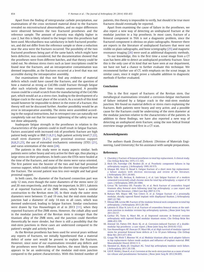
Apart from the finding of intergranular carbide precipitation, ourexaminations of the cross sectioned material distal to the fracturesrevealed no microstructural abnormalities, and no major differenceswere observed between the two fractured prostheses and thereference sample. The amount of porosity was slightly higher incase 2, but this is likely related to the longer time this prosthesis hadbeen used. Microhardness was satisfactory in both fractured prosthe-ses, and did not differ from the reference sample or show a reductionnear the area were the fractures occurred. The possibility of the twofractured prostheses being part of the same batch, which might havebeen defective, was considered, but the documentation showed thatthe prostheses were from different batches, and that theory could beruled out. No obvious stress risers such as laser inscriptions could befound near the fractures, and an intraoperative contamination wasdeemed impossible, as the fractures occurred at a level that was notaccessible during the intraoperative assembly.
Our examinations did thus not find any evidence of materialdefects which could have caused the fractures, and the question ofhow a material as strong as CoCrMo could fracture through fatigueafter such relatively short time remains unanswered. A possiblereason could be a small scratch from themanufacturing of the CoCrMopart, which would act as a stress riser, leading to the development of afatigue crack in the exact place of the scratch. As a scratch of this kindwould however be impossible to detect in the event of a fracture, thistheory will not be discussed further. Another possibility would be anerror in intraoperative assembly. The stems were assembled accord-ing to the surgical instructions, but in retrospect one can naturally notcompletely rule out that for instance tightening of the safety nut wasnot done adequately.
Inadequate fatigue strength in the prostheses in relation to thecharacteristics of the patients could in itself result in fatigue fracture.Factors associated with increased risk of prosthetic fracture are highpatient body weight or BMI [1,8,21], high patient activity level [7,22],small stem diameter [8,21], poor proximal osseous support[6,8,21,23], the use of extended trochanteric osteotomy (ETO) [21],and varus orientation of the stem [24].
The patients in this study were in many aspects similar; bothpatients were rather heavy and very active for their age, thus placing alarge stress on their prostheses. In both cases the ETOs were healed atthe time of the fractures, and none of the stems were varus oriented.The first patient was the heavier of the two and had bad proximalosseous support, which could explain the shorter time elapsed beforethe fracture. The second patient was less over-weight and had goodproximal support.
In both cases, the diameter of the fractured connection part wasonly 12 mm, even though the outer diameters of the stems were 22and 20 mm respectively, and this may be important. In 2011, Laksteinet al reported fractures of six ZMR stems, which have a similarconstruction to the Revitan stem [8]. In their study the outer stemdiameters were between 15 and 19 mm, but the mid-stem modularjunction had a diameter of only 14 mm in all cases, which wasdeemed undersized, leading to fatigue fracture. Similar conclusionswere drawn by Van Houwelingen et al in 2013 [11], when theyreported fractures of five ZMR stems. However, the cobalt alloy usedin the modular junction of the Revitan stem is stronger than thetitanium alloy of the ZMR stem, and the junction could thereforetheoretically be more slender, but there is still a possibility that themid-stem junctions in these cases are undersized compared to thepatient's weight and activity level.
As the Revitan prosthesis has been used for several years withoutany reports of fractures, we initially hypothesized that a materialdefect of some sort would be present to explain the fractures.However, since none of our examinations revealed any defects andthe prostheses were from different batches, the most likely reasonappears to be an undersizing of the modular mid-stem junctioncompared to the patient characteristics. With this limited number of
patients, this theory is impossible to verify, but should it be true morefractures should eventually be reported.
Apart from examining the cause of failure in the prostheses, wealso report a new way of detecting an undisplaced fracture at themodular junction in a hip prosthesis. In most cases, fracture of afemoral component in THA is not a diagnostic problem, since thefractured component is obvious on plain radiographs. However thereare reports in the literature of undisplaced fractures that were notvisible on plain radiographs, and bone scintigraphy [25] and magneticresonance imaging [26] were used as additional diagnostic methods.
To our knowledge, this is the first time a scout image from a CTscan has been able to detect an undisplaced prosthetic fracture. Sincethis is the only case of its kind that we have seen at our department,we have not had a chance to further evaluate this technique. Werecommend further use of CT, with emphasis on the scout image, insimilar cases, since it might prove a valuable addition to diagnosticmethods if further evaluated.
Conclusion
This is the first report of fractures of the Revitan stem. Ourmetallurgical examinations revealed a corrosion-fatigue mechanismof failure initiated by a fatigue crack in the mid-stem modularjunction. We found no material defects or stress risers explaining thefractures. Both patients were heavy and very active, and a possiblecause for the fractures could be undersizing of the stem diameter atthe modular junction relative to the characteristics of the patients. Inaddition to these findings, we have also reported a new way ofdetecting an undisplaced stem fracture, using the non-helical frontaloverview image performed first in a CT scan.
Acknowledgments
The authors thank Zivorad Zivkovic (Division of Materials Engi-neering, Lund University) for his assistance with sample preparations.
References
1. Charnley J. Fracture of femoral prostheses in total hip replacement. A clinical study.Clin Orthop Relat Res 1975;111:105.
2. Heck DA, Partridge CM, Reuben JD, et al. Prosthetic component failures in hiparthroplasty surgery. J Arthroplasty 1995;10:575.
3. Ishaque BA, Stürz H, Basad E. Fatigue fracture of a short stem hip replacement:a failure analysis with electron microscopy and review of the literature.J Arthroplasty 2011;26:665.
4. Della Valle AG, Becksaç B, Anderson J, et al. Late fatigue fracture of a moderncemented [corrected] cobalt chrome stem for total hip arthroplasty: a report of 10cases. J Arthroplasty 2005;20:1084.
5. Grivas TB, Savvidou OD, Psarakis SA, et al. Neck fracture of cementless forgedtitanium alloy femoral stem following total hip arthroplasty: a case report andreview of the literature. J Med Case Rep 2007;6:174.
6. Buttaro MA, Mayor MB, Van Citters D, et al. Fatigue fracture of a proximallymodular, distally tapered fluted implant with diaphyseal fixation. J Arthroplasty2007;22:780.
7. EllmanMB, Levine BR. Fracture of the modular femoral neck component in total hiparthroplasty. J Arthroplasty 2013;28:196.
8. Lakstein D, Eliaz N, Levi O, et al. Fracture of cementless femoral stems at the mid-stem junction in modular revision hip arthroplasty systems. J Bone Joint Surg Am2011;93:57.
9. Garbuz DS, Toms A, Masri BA, et al. Improved outcome in femoral revisionarthroplasty with tapered fluted modular titanium stems. Clin Orthop Relat Res2006;453:199.
10. Atwood SA, Patten EW, Bozic KJ, et al. Corrosion-induced fracture of a double-modular hip prosthesis: a case report. J Bone Joint Surg Am 2010;92:1522.
11. Van Houwelingen AP, Duncan CP, Masri BA, et al. High survival of modular taperedstems for proximal femoral bone defects at 5 to 10 years followup. Clin OrthopRelat Res 2013;471:454.
12. Grupp TM, Weik T, Bloemer W, et al. Modular titanium alloy neck adapter failuresin hip replacement–failure mode analysis and influence of implant material. BMCMusculoskelet Disord 2010;11:3.
13. Skendzel JG, Blaha JD, Urquhart AG. Total hip arthroplasty modular neck failure.J Arthroplasty 2011;26:338.
14. Gill IP,Webb J, Sloan K, et al. Corrosion at the neck-stem junction as a cause ofmetalion release and pseudotumor formation. J Bone Joint Surg Br 2012;94:895.

855P. Norman et al. / The Journal of Arthroplasty 29 (2014) 850–855
15. Fink B, Grossmann A, Schubring S, et al. Short-term results of hip revisions with acurved cementless modular stem in association with the surgical approach. ArchOrthop Trauma Surg 2009;129:65.
16. Young PS, Middleton RG, Learmonth ID, et al. Conversion of a long distally fixeduncemented revision femoral stem to a proximally fixed implant following fatiguefracture. Hip Int 2011;21:766.
17. Efe T, Schmitt J. Analyses of prosthesis stem failures in noncemented modular hiprevision prostheses. J Arthroplasty 2011;26:665.
18. Lee EW, Kim HT. Early fatigue failures of cemented, forged, cobalt–chromiumfemoral stems at the neck-shoulder junction. J Arthroplasty 2001;16:236.
19. Woolson ST, Milbauer JP, Bobyn JD, et al. Fatigue fracture of a forged cobalt–chromium–molybdenum femoral component inserted with cement. A report of tencases. J Bone Joint Surg Am 1997;79:1842.
20. Lam LO, Stoffel K, Kop A, et al. Catastrophic failure of 4 cobalt–alloy Omnifit hiparthroplasty femoral components. Acta Orthop 2008;79:18.
21. Busch CA, Charles MN, Haydon CM, et al. Fractures of distally-fixed femoral stemsafter revision arthroplasty. J Bone Joint Surg Br 2005;87:1333.
22. Gilbert JL, Buckley CA, Jacobs JJ, et al. Intergranular corrosion-fatigue failure ofcobalt–alloy femoral stems. A failure analysis of two implants. J Bone Joint Surg Am1994;76:110.
23. Landa J, Benke M, Dayan A, et al. Fracture of fully coated echelon femoral stems inrevision total hip arthroplasty. J Arthroplasty 2009;24:322.
24. Chao EY, Coventry MB. Fracture of the femoral component after total hipreplacement. An analysis of fifty-eight cases. J Bone Joint Surg Am 1981;63:1078.
25. Kishida Y, Sugano N, Ohzono K, et al. Stem fracture of the cementless spongy metalLübeck hip prosthesis. J Arthroplasty 2002;17:1021.
26. Cook SM, Pellicci PM, Potter HG. Use of magnetic resonance imaging in thediagnosis of an occult fracture of the femoral component after total hiparthroplasty. A case report. J Bone Joint Surg Am 2004;86:149.