Fast visual tracking and localization in multi-agent systems
7
Fast Visual Tracking and Localization in Multi-agent Systems Andelko Katalenic, Ivica Draganjac, Alan Mutka, Stjepan Bogdan Faculty of Electrical Engineering and Computing University of Zagreb Unska 3, 10000 Zagreb, Croatia E-mail:{andelko.katalenic, ivica.draganjac, alan.mutka, stjepan.bogdan}@fer.hr Abstract—In this paper an implementation of an algorithm for fast visual tracking and localization of mobile agents has been described. Based on an extremely rapid method for visual detection of an object, described localization strategy provides a real time solution suitable for the design of multi-agent control schemes. The agents tracking and localization is carried out through five differently trained cascades of classifiers that process images captured by cameras mounted on agents. In this way, each agent is able to determine relative positions and orientations of all other agents performing tasks in its field of view. The described localization method is suitable for applications involving robot formations. Performance of the proposed method has been demonstrated on a laboratory setup composed of two mobile robot platforms. Index Terms—Object detection, visual tracking, localization, mobile robots. I. I NTRODUCTION Control and coordination of agents in multi-agent systems is demanding and complex task. Applications like search and rescue [1], mapping of unknown environments or just simple moving in formation demands gathering a lot of information from surrounding. A local sensor-based information is pre- ferred in large formations due to observability constraints. On the other hand, local information processing requires sophisti- cated and expensive hardware that would manage to gather and process sensor information in real-time. Furthermore, refined sensors, such as a camera, entail time consuming algorithms. Generally, it is difficult to provide satisfactory results by implementation of such algorithms in real-time. For this reason immense research efforts have been put in development of fast and simple image analysis methods. This is specifically noticeable in the field of robot vision, a discipline that strives to solve problems such as robot localization and tracking, formation control, obstacle avoidance, grasping and so on. Visual tracking of robots in formation is usually based on visual markers. Algorithms for detection of predefined shapes or colors are simple enough to be executed even on low- cost embedded computers in real-time. In [2] pose estimation based on the tracking of color regions attached to the robot is presented. The position of the leader robot is estimated at video rate of 25 frames per second. The main disadvantage of the proposed method is marker position on the robot, i.e. a marker can be recognized only from particular angle. Authors in [3] accomplish robot identification and localization by using visual tags arranged on the back of each robot on a 3D- truncated octagonal-shaped structure. Each face of visual tag has a code that provides the vehicle’s ID as well as the position of the face in the 3D-visual marker. This information allows a vision sensor to identify the vehicle and estimate its pose relative to the sensor coordinate system. A robot formation control strategy based on visual pose estimation is presented in [4]. Robots visual perception is enhanced by the control of a motorized zoom, which gives the follower robot a large field of view and improves leader detection. Visual detection of an object without usage of additional markers might be very difficult. In some cases, it is important to recognize and localize an object that has to be picked up or manipulated (stationary object), while in other cases, it is paramount to identify and pinpoint an object that needs to be followed (object in motion). Object detection algorithms are usually based on matching captured images with stored object models. Tomono [5] proposed a high density indoor map-based visual navigation system on the basis of on-line recognition and shape reconstruction of 3D objects, using stored object models. However, the implemented Scale-invariant feature transform (SIFT) extraction is compute-intensive, and a real- time or even super-real-time processing capability is required to provide satisfactory results. Currently, the fastest object detection is provided by cascades of classifiers based on Haar- like features [6]. The cascades are trained using AdaBoost learning algorithm [7] and can be calculated very fast using integral image. In [8] real time on-road vehicle detection with optical flow and Haar-like feature is presented. The algorithm detects vehicles moving in the same direction up to 88% of accuracy. Fast vision-based pedestrian detection using Haar- like features is presented in [9]. Result shows that system can detect pedestrian at 17 frames per second on 1.7 GHz processor with pedestrian detection rate up to 90% of accuracy. Thorough review of image processing methods in visual navigation for mobile robots is given in [10]. In this paper we present an implementation of an algorithm for fast real-time visual tracking and localization in multi-agent system comprised of Wifibot mobile platforms [11]. Mobile platforms, equipped with IP cameras, are moving in formation that is established and maintained by using a visual feedback. Leader agent is followed by follower agent which uses only images captured by its camera as feedback information. 978–1–4244–2800–7/09/$25.00 c 2009 IEEE ICIEA 2009 1864
-
Upload
independent -
Category
Documents
-
view
4 -
download
0
Transcript of Fast visual tracking and localization in multi-agent systems

Fast Visual Tracking and Localization in Multi-agentSystems
Andelko Katalenic, Ivica Draganjac, Alan Mutka, Stjepan BogdanFaculty of Electrical Engineering and Computing
University of ZagrebUnska 3, 10000 Zagreb, Croatia
E-mail:{andelko.katalenic, ivica.draganjac, alan.mutka, stjepan.bogdan}@fer.hr
Abstract—In this paper an implementation of an algorithmfor fast visual tracking and localization of mobile agents hasbeen described. Based on an extremely rapid method for visualdetection of an object, described localization strategy provides areal time solution suitable for the design of multi-agent controlschemes. The agents tracking and localization is carried outthrough five differently trained cascades of classifiers that processimages captured by cameras mounted on agents. In this way, eachagent is able to determine relative positions and orientations of allother agents performing tasks in its field of view. The describedlocalization method is suitable for applications involving robotformations. Performance of the proposed method has beendemonstrated on a laboratory setup composed of two mobilerobot platforms.
Index Terms—Object detection, visual tracking, localization,mobile robots.
I. INTRODUCTION
Control and coordination of agents in multi-agent systemsis demanding and complex task. Applications like search andrescue [1], mapping of unknown environments or just simplemoving in formation demands gathering a lot of informationfrom surrounding. A local sensor-based information is pre-ferred in large formations due to observability constraints. Onthe other hand, local information processing requires sophisti-cated and expensive hardware that would manage to gather andprocess sensor information in real-time. Furthermore, refinedsensors, such as a camera, entail time consuming algorithms.Generally, it is difficult to provide satisfactory results byimplementation of such algorithms in real-time. For this reasonimmense research efforts have been put in development offast and simple image analysis methods. This is specificallynoticeable in the field of robot vision, a discipline that strivesto solve problems such as robot localization and tracking,formation control, obstacle avoidance, grasping and so on.Visual tracking of robots in formation is usually based onvisual markers. Algorithms for detection of predefined shapesor colors are simple enough to be executed even on low-cost embedded computers in real-time. In [2] pose estimationbased on the tracking of color regions attached to the robotis presented. The position of the leader robot is estimated atvideo rate of 25 frames per second. The main disadvantageof the proposed method is marker position on the robot, i.e. amarker can be recognized only from particular angle. Authorsin [3] accomplish robot identification and localization by using
visual tags arranged on the back of each robot on a 3D-truncated octagonal-shaped structure. Each face of visual taghas a code that provides the vehicle’s ID as well as the positionof the face in the 3D-visual marker. This information allowsa vision sensor to identify the vehicle and estimate its poserelative to the sensor coordinate system. A robot formationcontrol strategy based on visual pose estimation is presentedin [4]. Robots visual perception is enhanced by the control ofa motorized zoom, which gives the follower robot a large fieldof view and improves leader detection.
Visual detection of an object without usage of additionalmarkers might be very difficult. In some cases, it is importantto recognize and localize an object that has to be picked upor manipulated (stationary object), while in other cases, it isparamount to identify and pinpoint an object that needs to befollowed (object in motion). Object detection algorithms areusually based on matching captured images with stored objectmodels. Tomono [5] proposed a high density indoor map-basedvisual navigation system on the basis of on-line recognitionand shape reconstruction of 3D objects, using stored objectmodels. However, the implemented Scale-invariant featuretransform (SIFT) extraction is compute-intensive, and a real-time or even super-real-time processing capability is requiredto provide satisfactory results. Currently, the fastest objectdetection is provided by cascades of classifiers based on Haar-like features [6]. The cascades are trained using AdaBoostlearning algorithm [7] and can be calculated very fast usingintegral image. In [8] real time on-road vehicle detection withoptical flow and Haar-like feature is presented. The algorithmdetects vehicles moving in the same direction up to 88% ofaccuracy. Fast vision-based pedestrian detection using Haar-like features is presented in [9]. Result shows that system candetect pedestrian at 17 frames per second on 1.7 GHz processorwith pedestrian detection rate up to 90% of accuracy. Thoroughreview of image processing methods in visual navigation formobile robots is given in [10].
In this paper we present an implementation of an algorithmfor fast real-time visual tracking and localization in multi-agentsystem comprised of Wifibot mobile platforms [11]. Mobileplatforms, equipped with IP cameras, are moving in formationthat is established and maintained by using a visual feedback.Leader agent is followed by follower agent which uses onlyimages captured by its camera as feedback information.
978–1–4244–2800–7/09/$25.00 c© 2009 IEEE ICIEA 20091864
The paper is organized as follows. In section 2 algorithm forfast object detection, using Haar-like features and integral im-age has been introduced. Next follows the description of strongclassifiers and cascades of classifiers. Section 3 introduces themethod for the platform position and orientation detection,using five differently trained cascades of classifiers. In section4, the laboratory setup for platform tracking, comprised oftwo Wifibot platforms is described. Experimental results onplatform localization are given in section 5.
II. FAST VISUAL DETECTION ALGORITHM
A. Features and integral image
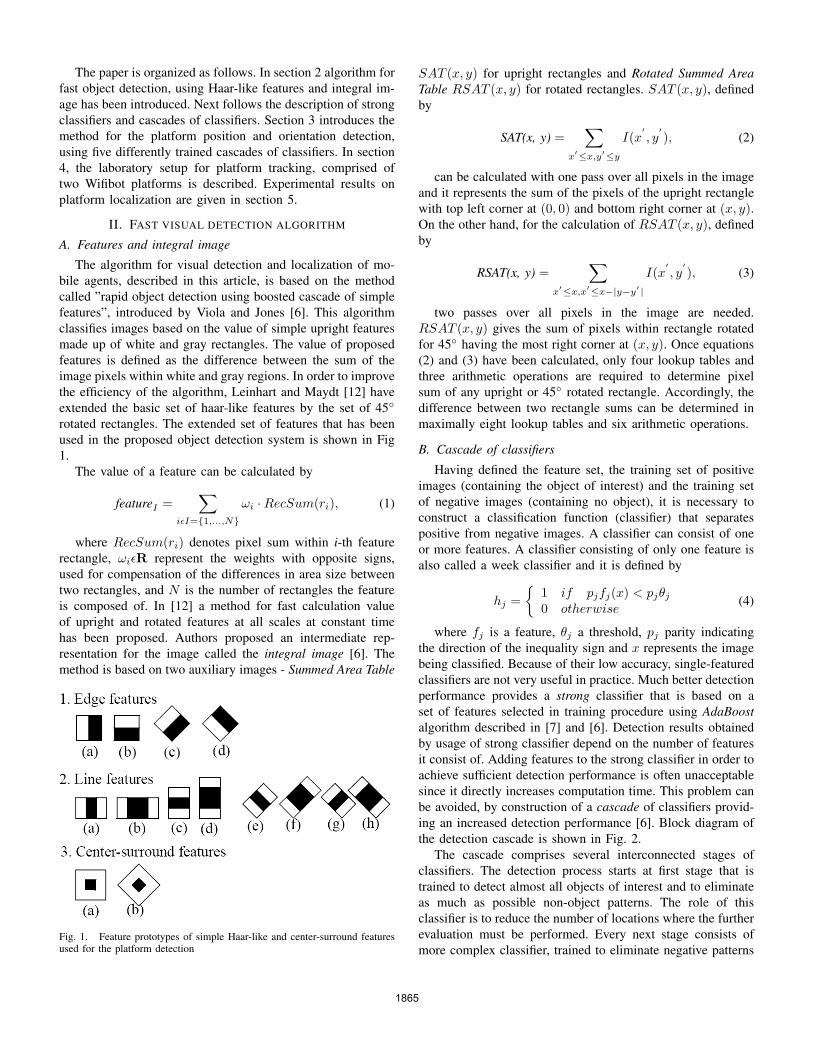
The algorithm for visual detection and localization of mo-bile agents, described in this article, is based on the methodcalled ”rapid object detection using boosted cascade of simplefeatures”, introduced by Viola and Jones [6]. This algorithmclassifies images based on the value of simple upright featuresmade up of white and gray rectangles. The value of proposedfeatures is defined as the difference between the sum of theimage pixels within white and gray regions. In order to improvethe efficiency of the algorithm, Leinhart and Maydt [12] haveextended the basic set of haar-like features by the set of 45◦
rotated rectangles. The extended set of features that has beenused in the proposed object detection system is shown in Fig1.
The value of a feature can be calculated by
featureI =∑
iεI={1,...,N}ωi ·RecSum(ri), (1)
where RecSum(ri) denotes pixel sum within i-th featurerectangle, ωiεR represent the weights with opposite signs,used for compensation of the differences in area size betweentwo rectangles, and N is the number of rectangles the featureis composed of. In [12] a method for fast calculation valueof upright and rotated features at all scales at constant timehas been proposed. Authors proposed an intermediate rep-resentation for the image called the integral image [6]. Themethod is based on two auxiliary images - Summed Area Table
Fig. 1. Feature prototypes of simple Haar-like and center-surround featuresused for the platform detection
SAT (x, y) for upright rectangles and Rotated Summed AreaTable RSAT (x, y) for rotated rectangles. SAT (x, y), definedby
SAT(x, y) =∑
x′≤x,y′≤y
I(x′, y′), (2)
can be calculated with one pass over all pixels in the imageand it represents the sum of the pixels of the upright rectanglewith top left corner at (0, 0) and bottom right corner at (x, y).On the other hand, for the calculation of RSAT (x, y), definedby
RSAT(x, y) =∑
x′≤x,x′≤x−|y−y′ |I(x
′, y′), (3)
two passes over all pixels in the image are needed.RSAT (x, y) gives the sum of pixels within rectangle rotatedfor 45◦ having the most right corner at (x, y). Once equations(2) and (3) have been calculated, only four lookup tables andthree arithmetic operations are required to determine pixelsum of any upright or 45◦ rotated rectangle. Accordingly, thedifference between two rectangle sums can be determined inmaximally eight lookup tables and six arithmetic operations.
B. Cascade of classifiers
Having defined the feature set, the training set of positiveimages (containing the object of interest) and the training setof negative images (containing no object), it is necessary toconstruct a classification function (classifier) that separatespositive from negative images. A classifier can consist of oneor more features. A classifier consisting of only one feature isalso called a week classifier and it is defined by
hj ={
1 if pjfj(x) < pjθj
0 otherwise(4)
where fj is a feature, θj a threshold, pj parity indicatingthe direction of the inequality sign and x represents the imagebeing classified. Because of their low accuracy, single-featuredclassifiers are not very useful in practice. Much better detectionperformance provides a strong classifier that is based on aset of features selected in training procedure using AdaBoostalgorithm described in [7] and [6]. Detection results obtainedby usage of strong classifier depend on the number of featuresit consist of. Adding features to the strong classifier in order toachieve sufficient detection performance is often unacceptablesince it directly increases computation time. This problem canbe avoided, by construction of a cascade of classifiers provid-ing an increased detection performance [6]. Block diagram ofthe detection cascade is shown in Fig. 2.
The cascade comprises several interconnected stages ofclassifiers. The detection process starts at first stage that istrained to detect almost all objects of interest and to eliminateas much as possible non-object patterns. The role of thisclassifier is to reduce the number of locations where the furtherevaluation must be performed. Every next stage consists ofmore complex classifier, trained to eliminate negative patterns
1865
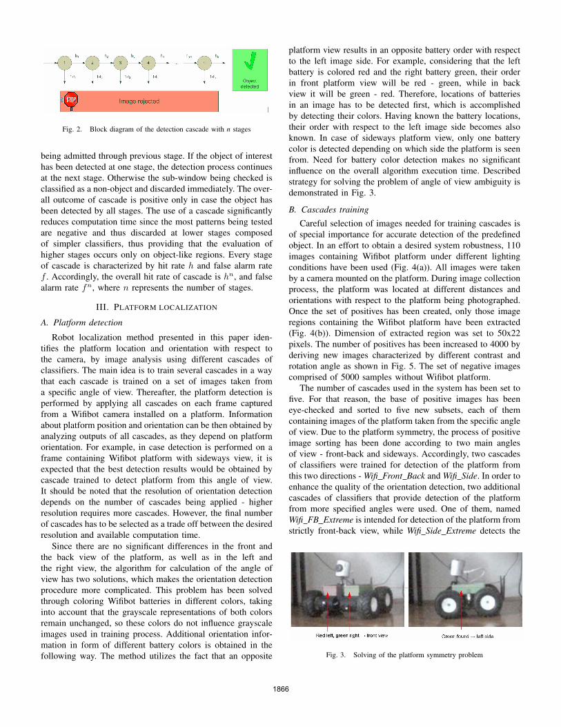
Fig. 2. Block diagram of the detection cascade with n stages
being admitted through previous stage. If the object of interesthas been detected at one stage, the detection process continuesat the next stage. Otherwise the sub-window being checked isclassified as a non-object and discarded immediately. The over-all outcome of cascade is positive only in case the object hasbeen detected by all stages. The use of a cascade significantlyreduces computation time since the most patterns being testedare negative and thus discarded at lower stages composedof simpler classifiers, thus providing that the evaluation ofhigher stages occurs only on object-like regions. Every stageof cascade is characterized by hit rate h and false alarm ratef . Accordingly, the overall hit rate of cascade is hn, and falsealarm rate fn, where n represents the number of stages.
III. PLATFORM LOCALIZATION
A. Platform detection
Robot localization method presented in this paper iden-tifies the platform location and orientation with respect tothe camera, by image analysis using different cascades ofclassifiers. The main idea is to train several cascades in a waythat each cascade is trained on a set of images taken froma specific angle of view. Thereafter, the platform detection isperformed by applying all cascades on each frame capturedfrom a Wifibot camera installed on a platform. Informationabout platform position and orientation can be then obtained byanalyzing outputs of all cascades, as they depend on platformorientation. For example, in case detection is performed on aframe containing Wifibot platform with sideways view, it isexpected that the best detection results would be obtained bycascade trained to detect platform from this angle of view.It should be noted that the resolution of orientation detectiondepends on the number of cascades being applied - higherresolution requires more cascades. However, the final numberof cascades has to be selected as a trade off between the desiredresolution and available computation time.
Since there are no significant differences in the front andthe back view of the platform, as well as in the left andthe right view, the algorithm for calculation of the angle ofview has two solutions, which makes the orientation detectionprocedure more complicated. This problem has been solvedthrough coloring Wifibot batteries in different colors, takinginto account that the grayscale representations of both colorsremain unchanged, so these colors do not influence grayscaleimages used in training process. Additional orientation infor-mation in form of different battery colors is obtained in thefollowing way. The method utilizes the fact that an opposite
platform view results in an opposite battery order with respectto the left image side. For example, considering that the leftbattery is colored red and the right battery green, their orderin front platform view will be red - green, while in backview it will be green - red. Therefore, locations of batteriesin an image has to be detected first, which is accomplishedby detecting their colors. Having known the battery locations,their order with respect to the left image side becomes alsoknown. In case of sideways platform view, only one batterycolor is detected depending on which side the platform is seenfrom. Need for battery color detection makes no significantinfluence on the overall algorithm execution time. Describedstrategy for solving the problem of angle of view ambiguity isdemonstrated in Fig. 3.
B. Cascades training
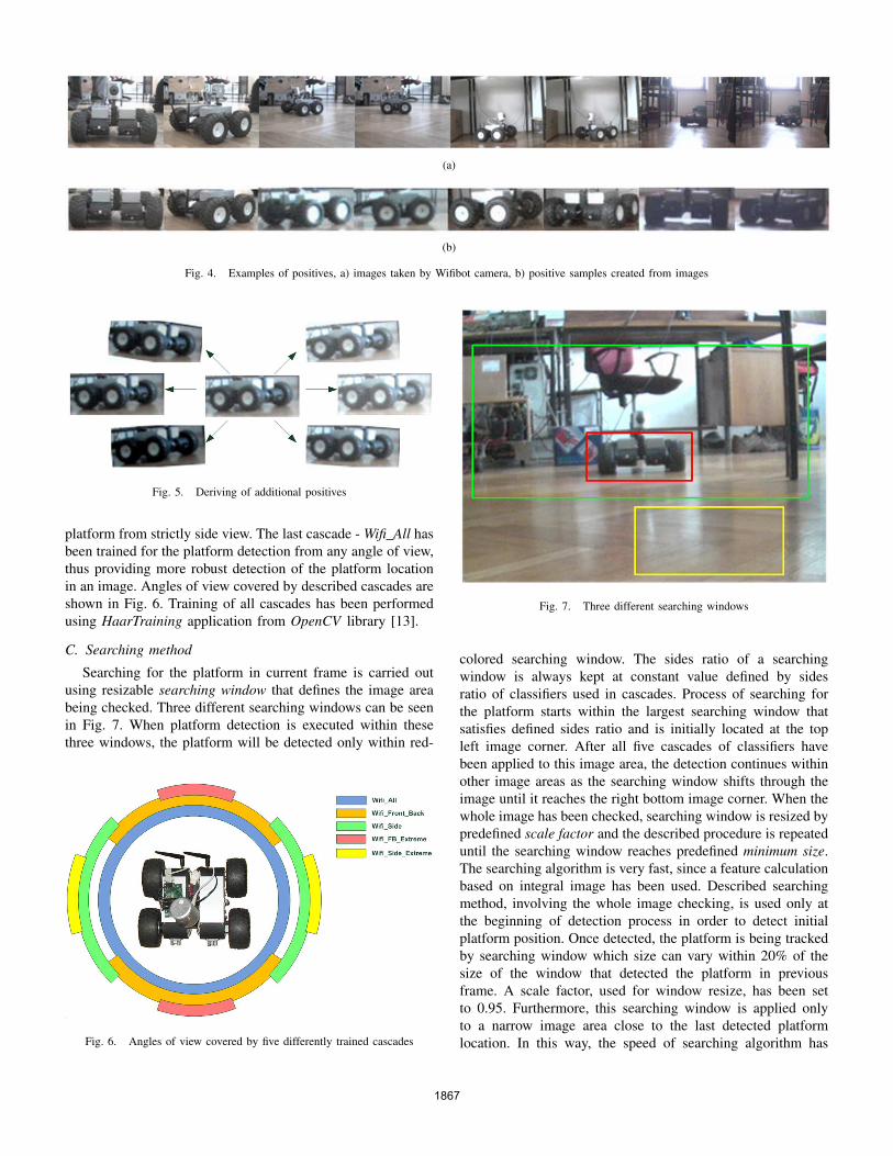
Careful selection of images needed for training cascades isof special importance for accurate detection of the predefinedobject. In an effort to obtain a desired system robustness, 110images containing Wifibot platform under different lightingconditions have been used (Fig. 4(a)). All images were takenby a camera mounted on the platform. During image collectionprocess, the platform was located at different distances andorientations with respect to the platform being photographed.Once the set of positives has been created, only those imageregions containing the Wifibot platform have been extracted(Fig. 4(b)). Dimension of extracted region was set to 50x22pixels. The number of positives has been increased to 4000 byderiving new images characterized by different contrast androtation angle as shown in Fig. 5. The set of negative imagescomprised of 5000 samples without Wifibot platform.
The number of cascades used in the system has been set tofive. For that reason, the base of positive images has beeneye-checked and sorted to five new subsets, each of themcontaining images of the platform taken from the specific angleof view. Due to the platform symmetry, the process of positiveimage sorting has been done according to two main anglesof view - front-back and sideways. Accordingly, two cascadesof classifiers were trained for detection of the platform fromthis two directions - Wifi Front Back and Wifi Side. In order toenhance the quality of the orientation detection, two additionalcascades of classifiers that provide detection of the platformfrom more specified angles were used. One of them, namedWifi FB Extreme is intended for detection of the platform fromstrictly front-back view, while Wifi Side Extreme detects the
Fig. 3. Solving of the platform symmetry problem
1866
(a)
(b)
Fig. 4. Examples of positives, a) images taken by Wifibot camera, b) positive samples created from images
Fig. 5. Deriving of additional positives
platform from strictly side view. The last cascade - Wifi All hasbeen trained for the platform detection from any angle of view,thus providing more robust detection of the platform locationin an image. Angles of view covered by described cascades areshown in Fig. 6. Training of all cascades has been performedusing HaarTraining application from OpenCV library [13].
C. Searching method
Searching for the platform in current frame is carried outusing resizable searching window that defines the image areabeing checked. Three different searching windows can be seenin Fig. 7. When platform detection is executed within thesethree windows, the platform will be detected only within red-
Fig. 6. Angles of view covered by five differently trained cascades
Fig. 7. Three different searching windows
colored searching window. The sides ratio of a searchingwindow is always kept at constant value defined by sidesratio of classifiers used in cascades. Process of searching forthe platform starts within the largest searching window thatsatisfies defined sides ratio and is initially located at the topleft image corner. After all five cascades of classifiers havebeen applied to this image area, the detection continues withinother image areas as the searching window shifts through theimage until it reaches the right bottom image corner. When thewhole image has been checked, searching window is resized bypredefined scale factor and the described procedure is repeateduntil the searching window reaches predefined minimum size.The searching algorithm is very fast, since a feature calculationbased on integral image has been used. Described searchingmethod, involving the whole image checking, is used only atthe beginning of detection process in order to detect initialplatform position. Once detected, the platform is being trackedby searching window which size can vary within 20% of thesize of the window that detected the platform in previousframe. A scale factor, used for window resize, has been setto 0.95. Furthermore, this searching window is applied onlyto a narrow image area close to the last detected platformlocation. In this way, the speed of searching algorithm has
1867
been additionally increased. The algorithm was able to process15 frames per second on 3.0 GHz Pentium IV processor with1GB RAM.
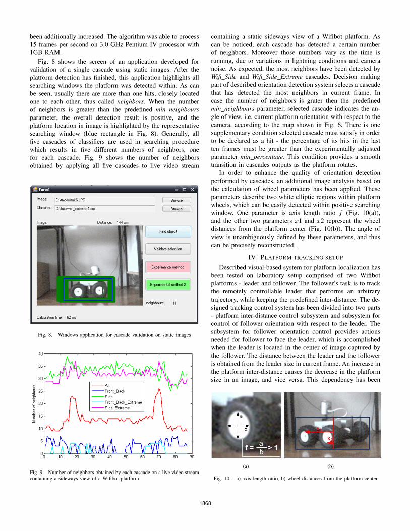
Fig. 8 shows the screen of an application developed forvalidation of a single cascade using static images. After theplatform detection has finished, this application highlights allsearching windows the platform was detected within. As canbe seen, usually there are more than one hits, closely locatedone to each other, thus called neighbors. When the numberof neighbors is greater than the predefined min neighboursparameter, the overall detection result is positive, and theplatform location in image is highlighted by the representativesearching window (blue rectangle in Fig. 8). Generally, allfive cascades of classifiers are used in searching procedurewhich results in five different numbers of neighbors, onefor each cascade. Fig. 9 shows the number of neighborsobtained by applying all five cascades to live video stream
Fig. 8. Windows application for cascade validation on static images
Fig. 9. Number of neighbors obtained by each cascade on a live video streamcontaining a sideways view of a Wifibot platform
containing a static sideways view of a Wifibot platform. Ascan be noticed, each cascade has detected a certain numberof neighbors. Moreover those numbers vary as the time isrunning, due to variations in lightning conditions and cameranoise. As expected, the most neighbors have been detected byWifi Side and Wifi Side Extreme cascades. Decision makingpart of described orientation detection system selects a cascadethat has detected the most neighbors in current frame. Incase the number of neighbors is grater then the predefinedmin neighbours parameter, selected cascade indicates the an-gle of view, i.e. current platform orientation with respect to thecamera, according to the map shown in Fig. 6. There is onesupplementary condition selected cascade must satisfy in orderto be declared as a hit - the percentage of its hits in the lastten frames must be greater than the experimentally adjustedparameter min percentage. This condition provides a smoothtransition in cascades outputs as the platform rotates.
In order to enhance the quality of orientation detectionperformed by cascades, an additional image analysis based onthe calculation of wheel parameters has been applied. Theseparameters describe two white elliptic regions within platformwheels, which can be easily detected within positive searchingwindow. One parameter is axis length ratio f (Fig. 10(a)),and the other two parameters x1 and x2 represent the wheeldistances from the platform center (Fig. 10(b)). The angle ofview is unambiguously defined by these parameters, and thuscan be precisely reconstructed.
IV. PLATFORM TRACKING SETUP
Described visual-based system for platform localization hasbeen tested on laboratory setup comprised of two Wifibotplatforms - leader and follower. The follower’s task is to trackthe remotely controllable leader that performs an arbitrarytrajectory, while keeping the predefined inter-distance. The de-signed tracking control system has been divided into two parts- platform inter-distance control subsystem and subsystem forcontrol of follower orientation with respect to the leader. Thesubsystem for follower orientation control provides actionsneeded for follower to face the leader, which is accomplishedwhen the leader is located in the center of image captured bythe follower. The distance between the leader and the followeris obtained from the leader size in current frame. An increase inthe platform inter-distance causes the decrease in the platformsize in an image, and vice versa. This dependency has been
(a) (b)
Fig. 10. a) axis length ratio, b) wheel distances from the platform center
1868
experimentally obtained. Once cascades detect position of theplatform a distance from camera is calculated based on thewidth of the frame determined from neighbors (blue rectanglein Fig. 8). A function of distance with respect to width has thefollowing form:
d(w) = 50850 · e−0.07287·w + 311.2 · e−0.005298·w (5)
It is evident that relation between width of an object andits distance from a camera is not linear which is characteristicof human eye as well.
The difference between current and desired platform inter-distance causes the follower forward/backward motion, whilethe leader’s displacement from the image center causes thefollower rotation until the leader appears in the image center.Block diagram of the designed control system, containingtwo described subsystems, is shown in Fig. 11. The controlalgorithm with sample time of Td = 50 ms, has been executedon 3.0 GHz Pentium IV processor, while the camera imagesand commands for platform motion have been transmittedtrough the wireless network established between PC and accesspoint embedded in the platform. Due to the noise in angleand distance measurement Median and MaxChange filters havebeen added in the feedback loop. For correct design of trackingcontrollers an additional delay of 250 ms (5xTd), caused byimage capture and processing by the camera on board ofthe platform, is introduced in the feedback loop. Proportionalcontrollers have been used for both - distance and orientationcontrol.
V. EXPERIMENTAL RESULTS
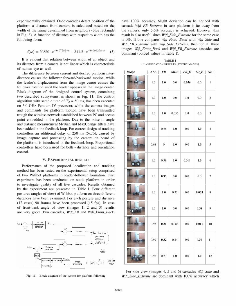
Performance of the proposed localization and trackingmethod has been tested on the experimental setup comprisedof two Wifibot platforms in leader-follower formation. Firstexperiment has been conducted on static platform in orderto investigate quality of all five cascades. Results obtainedby the experiment are presented in Table I. Four differentpostures (angles of view) of Wifibot platform on three differentdistances have been examined. For each posture and distance(12 cases) 90 frames have been processed (15 fps). In caseof front-back angle of view (images 1, 2 and 3) resultsare very good. Two cascades, Wifi All and Wifi Front Back,
Fig. 11. Block diagram of the system for platform following
have 100% accuracy. Slight deviation can be noticed withcascade Wifi FB Extreme in case platform is far away fromthe camera; only 5.6% accuracy is achieved. However, thisresult is also useful since Wifi Side Extreme for the same caseis 0%. If one compares Wifi Front Back with Wifi Side andWifi FB Extreme with Wifi Side Extreme, then for all threeimages Wifi Front Back and Wifi FB Extreme cascades aredominant (bolded values in Table I).
TABLE ICLASSIFICATION RESULTS (STATIC IMAGES)
Image ALL FB SIDE FB E SD E No.
1.0 1.0 0.0 0.056 0.0 1
1.0 1.0 0.0 1.0 0.0 2
1.0 1.0 0.056 1.0 0.0 3
1.0 0.26 1.0 0.0 1.0 4
0.68 0 1.0 0.0 1.0 5
1.0 0.39 1.0 0.011 1.0 6
1.0 0.95 0.0 0.0 0.0 7
1.0 1.0 0.32 0.0 0.033 8
1.0 1.0 0.0 0.0 0.38 9
0.95 0.31 0.088 0.0 0.011 10
0.99 0.32 0.24 0.0 0.39 11
0.93 0.23 1.0 0.0 1.0 12
For side view (images 4, 5 and 6) cascades Wifi Side andWifi Side Extreme are dominant with 100% accuracy which
1869
is exceptionally good result. Results obtained for conditionswhen angle of view was somewhere between front-back andside view are demonstrated on images 7 to 12. Althoughsituation is not as clear as for previous examples, in mostcases Wifi Front Back and Wifi Side Extreme cascades aredominant, which demonstrates that platform is inclined.
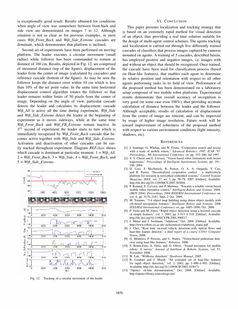
Second set of experiments have been performed on movingplatform. The leader executes a circular movement (smallradius) while follower has been commanded to remain atdistance of 160 cm. Results, depicted in Fig. 12, are comprisedof measured distance (top of the figure), displacement of theleader from the center of image (calculated by cascades) andreference cascade (bottom of the figure). As may be seen thefollower keeps the distance error within 10 cm which is lessthan 10% of the set point value. In the same time horizontaldisplacement control algorithm rotates the follower so thatleader remains within limits of 50 pixels from the center ofimage. Depending on the angle of view, particular cascadedetects the leader and calculates its displacement: cascadeWifi All is active all the time during experiment, Wifi Sideand Wifi Side Extreme detect the leader at the beginning ofexperiment as it moves sideways, while at the same timeWifi Front Back and Wifi FB Extreme remain inactive. In3th second of experiment the leader starts to turn which isimmediately recognized by Wifi Front Back cascade that be-comes active together with Wifi Side and Wifi Side Extreme.Activation and deactivation of other cascades can be eas-ily tracked throughout experiment. Diagram REFclass showswhich cascade is dominant at particular moment: 1 = Wifi All,2 = Wifi Front Back, 3 = Wifi Side, 4 = Wifi Front Back, and5 = Wifi Side Extreme.
Fig. 12. Tracking of a circular movement of the leader
VI. CONCLUSION
This paper presents localization and tracking strategy thatis based on an extremely rapid method for visual detectionof an object, thus providing a real time solution suitable forthe design of multi-agent control schemes. The agents trackingand localization is carried out through five differently trainedcascades of classifiers that process images captured by camerasmounted on agents. A training of 5 cascades, described herein,has employed positive and negative images, i.e. images withand without an object that should be recognized. Once trained,the cascade have been used for classification process (basedon Haar-like features), that enables each agent to determineits relative position and orientation with respect to all otheragents performing tasks in its field of view. Performance ofthe proposed method has been demonstrated on a laboratorysetup composed of two mobile robot platforms. Experimentalresults demonstrate that overall accuracy of recognition isvery good (in some case even 100%), thus providing accuratecalculation of distance between the leader and the follower.Although acceptable, results of calculation of displacementfrom the center of image are reticent, and can be improvedby usage of higher image resolution. Future work will betoward improvement of robustness of the proposed methodwith respect to various environment conditions (light intensity,shadows, etc).
REFERENCES
[1] J. Jennings, G. Whelan, and W. Evans, “Cooperative search and rescuewith a team of mobile robots,” Advanced Robotics, 1997. ICAR ’97.Proceedings., 8th International Conference on, pp. 193–200, Jul 1997.
[2] S. Y. Chiem and E. Cervera, “Vision-based robot formations with beziertrajectories,” Proceedings of Intelligent Autonomous Systems, pp. 191–198, 2004.
[3] D. Cruz, J. Mcclintock, B. Perteet, O. A. A. Orqueda, Y. Cao,and R. Fierro, “Decentralized cooperative control - a multivehicleplatform for research in networked embedded systems,” Control SystemsMagazine, IEEE, vol. 27, no. 3, pp. 58–78, 2007. [Online]. Available:http://dx.doi.org/10.1109/MCS.2007.365004
[4] P. Renaud, E. Cervera, and P. Martiner, “Towards a reliable vision-basedmobile robot formation control,” Intelligent Robots and Systems, 2004.(IROS 2004). Proceedings. 2004 IEEE/RSJ International Conference on,vol. 4, pp. 3176–3181, Sept.-2 Oct. 2004.
[5] M. Tomono, “3-d object map building using dense object models withsift-based recognition features,” Intelligent Robots and Systems, 2006IEEE/RSJ International Conference on, pp. 1885–1890, Oct. 2006.
[6] P. Viola and M. Jones, “Rapid object detection using a boosted cascadeof simple features,” vol. 1, 2001, pp. I–511–I–518. [Online]. Available:http://dx.doi.org/10.1109/CVPR.2001.990517
[7] J. Matas and J. Sochman, “Adaboost,” Oct. 2008. [Online]. Available:http://www.robots.ox.ac.uk/ az/lectures/cv/adaboost matas.pdf
[8] J. Choi, “Real time on-road vehicle detection with optical flows andhaar-like feature detector,” a final report of a course CS543 ComputerVision, 2006.
[9] G. Monteiro, P. Peixoto, and U. Nunes, “Vision-based pedestrian dete-cion using haar-like features,” Robotica, 2006.
[10] F. Bonin-Font, A. Ortiz, and G. Oliver, “Visual naviation for mobilerobots: A survey,” Journal of Intellient & Robotic Systems, vol. 53,November 2008.
[11] W. Lab, “Wifibotsc datasheet,” Hardware Manual, 2005.[12] R. Lienhart and J. Maydt, “An extended set of haar-like features
for rapid object detection,” vol. 1, 2002, pp. I–900–I–903. [Online].Available: http://dx.doi.org/10.1109/ICIP.2002.1038171
[13] “Opencv on-line documentation,” Oct. 2008. [Online]. Available:http://opencvlibrary.sourceforge.net/
1870