Failure Modes, Effects and Diagnostic Analysis - R. STAHL
19
The document was prepared using best effort. The authors make no warranty of any kind and shall not be liable in any event for incidental or consequential damages in connection with the application of the document. © All rights on the format of this technical report reserved. Failure Modes, Effects and Diagnostic Analysis Project: Relay Module 9172 Company: R. STAHL Schaltgeräte GmbH Waldenburg Germany Contract No.: STAHL 13/11-017 Report No.: STAHL 13/11-017 R031 Version V1, Revision R3; February 2019 Jan Hettenbach
-
Upload
khangminh22 -
Category
Documents
-
view
4 -
download
0
Transcript of Failure Modes, Effects and Diagnostic Analysis - R. STAHL

The document was prepared using best effort. The authors make no warranty of any kind and shall not be liable in any event for incidental or consequential damages in connection with the application of the document.
© All rights on the format of this technical report reserved.
Failure Modes, Effects and Diagnostic Analysis
Project:
Relay Module 9172
Company:
R. STAHL Schaltgeräte GmbH
Waldenburg
Germany
Contract No.: STAHL 13/11-017
Report No.: STAHL 13/11-017 R031
Version V1, Revision R3; February 2019
Jan Hettenbach
© exida.com GmbH STAHL 9172_13-11-017_R031_V1R3.doc; February 5, 2019 Jan Hettenbach Page 2 of 3
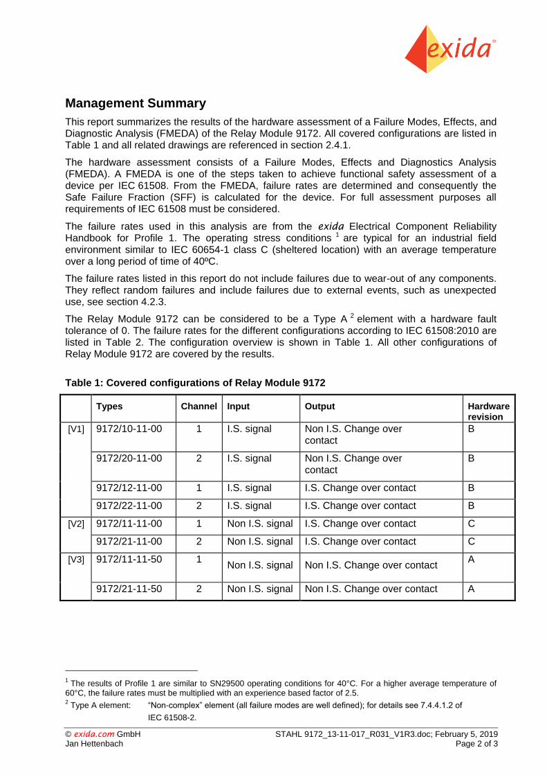
Management Summary
This report summarizes the results of the hardware assessment of a Failure Modes, Effects, and Diagnostic Analysis (FMEDA) of the Relay Module 9172. All covered configurations are listed in Table 1 and all related drawings are referenced in section 2.4.1.
The hardware assessment consists of a Failure Modes, Effects and Diagnostics Analysis (FMEDA). A FMEDA is one of the steps taken to achieve functional safety assessment of a device per IEC 61508. From the FMEDA, failure rates are determined and consequently the Safe Failure Fraction (SFF) is calculated for the device. For full assessment purposes all requirements of IEC 61508 must be considered.
The failure rates used in this analysis are from the exida Electrical Component Reliability Handbook for Profile 1. The operating stress conditions 1 are typical for an industrial field environment similar to IEC 60654-1 class C (sheltered location) with an average temperature over a long period of time of 40ºC.
The failure rates listed in this report do not include failures due to wear-out of any components. They reflect random failures and include failures due to external events, such as unexpected use, see section 4.2.3.
The Relay Module 9172 can be considered to be a Type A 2 element with a hardware fault tolerance of 0. The failure rates for the different configurations according to IEC 61508:2010 are listed in Table 2. The configuration overview is shown in Table 1. All other configurations of Relay Module 9172 are covered by the results.
Table 1: Covered configurations of Relay Module 9172
Types
Channel Input Output Hardware revision
[V1] 9172/10-11-00 1 I.S. signal Non I.S. Change over contact
B
9172/20-11-00 2 I.S. signal Non I.S. Change over contact
B
9172/12-11-00 1 I.S. signal I.S. Change over contact B
9172/22-11-00 2 I.S. signal I.S. Change over contact B
[V2] 9172/11-11-00 1 Non I.S. signal I.S. Change over contact C
9172/21-11-00 2 Non I.S. signal I.S. Change over contact C
[V3] 9172/11-11-50
1 Non I.S. signal Non I.S. Change over contact
A
9172/21-11-50 2 Non I.S. signal Non I.S. Change over contact A
1 The results of Profile 1 are similar to SN29500 operating conditions for 40°C. For a higher average temperature of
60°C, the failure rates must be multiplied with an experience based factor of 2.5. 2
PT Type A element: “Non-complex” element (all failure modes are well defined); for details see 7.4.4.1.2 of
IEC 61508-2.

© exida.com GmbH STAHL 9172_13-11-017_R031_V1R3.doc; February 5, 2019 Jan Hettenbach Page 3 of 3
Table 2: Failure rates Relay Module 9172 [V1] to [V3] 3
exida Profile 1
Failure category Failure rates (in FIT)
Fail Safe Detected (SD) 0
Fail Safe Undetected (SU) 41
Fail Dangerous Detected (DD) 0
Fail Dangerous Undetected (DU) 25
Fail Annunciation Undetected (AU) 0
No effect 20
No part 2
Total failure rate (safety function) 66
Safe failure fraction (SFF ) 4 62%
SIL AC 5 SIL2
3 The failure rates are the worst case results of versions [V1] to [V3].
4 The complete final element subsystem will need to be evaluated to determine the overall Safe Failure Fraction. The
number listed is for reference only. 5 SIL AC (architectural constraints) means that the calculated values are within the range for hardware architectural
constraints for the corresponding SIL but does not imply all related IEC 61508 requirements are fulfilled. The SIL AC (architectural constraints) needs to be evaluated on subsystem level.

© exida.com GmbH STAHL 9172_13-11-017_R031_V1R3.doc; February 5, 2019 Jan Hettenbach Page 4 of 19
Table of Contents
Management Summary ................................................................................................... 2
1 Purpose and Scope ................................................................................................. 5
2 Project Management ............................................................................................... 6
2.1 exida ............................................................................................................................. 6
2.2 Roles of the parties involved.......................................................................................... 6
2.3 Standards and Literature used ...................................................................................... 6
2.4 Reference documents ................................................................................................... 7
2.4.1 Documentation provided by the customer ................................................................. 7
2.4.2 Documentation generated by exida .......................................................................... 7
2.5 exida tools used ............................................................................................................ 7
3 Product Description ................................................................................................. 8
3.1 I.S. Relay Module 9172 ................................................................................................. 8
4 Failure Modes, Effects, and Diagnostic Analysis ..................................................... 9
4.1 Description of the failure categories .............................................................................. 9
4.2 Methodology – FMEDA, Failure Rates ........................................................................ 10
4.2.1 FMEDA .................................................................................................................... 10
4.2.2 Failure Rates ........................................................................................................... 10
4.2.3 Assumptions ............................................................................................................ 11
4.3 Results of the assessment .......................................................................................... 12
4.3.1 Results of Relay Module 9172 ................................................................................. 13
5 Using the FMEDA Results .................................................................................... 14
5.1 Example PFDAVG calculation ........................................................................................ 14
6 Terms and Definitions ........................................................................................... 15
7 Status of the Document ......................................................................................... 16
7.1 Liability ......................................................................................................................... 16
7.2 Releases ...................................................................................................................... 16
7.3 Release Signatures ..................................................................................................... 16
Appendix A: Possibilities to reveal dangerous undetected faults during the proof test .. 17
Appendix A.1: Possible proof tests to detect dangerous undetected faults ............................ 17
Appendix B: Impact of lifetime of critical components on the failure rate ....................... 18
Appendix C: exida Environmental Profiles .................................................................... 19

© exida.com GmbH STAHL 9172_13-11-017_R031_V1R3.doc; February 5, 2019 Jan Hettenbach Page 5 of 19
1 Purpose and Scope
This document shall describe the results of the hardware assessment in the form of the Failure Modes, Effects and Diagnostic Analysis carried out on the Relay Module 9172.
The FMEDA builds the basis for an evaluation whether a final element subsystem, including the described Relay Module 9172 meets the average Probability of Failure on Demand (PFDAVG) requirements and if applicable the architectural constraints / minimum hardware fault tolerance requirements per IEC 61508 / IEC 61511. It does not consider any calculations necessary for proving intrinsic safety.

© exida.com GmbH STAHL 9172_13-11-017_R031_V1R3.doc; February 5, 2019 Jan Hettenbach Page 6 of 19
2 Project Management
2.1 exida
exida is one of the world’s leading product certification and knowledge companies specializing in automation system safety and availability with over 300 years of cumulative experience in functional safety. Founded by several of the world’s top reliability and safety experts from
assessment organizations and manufacturers, exida is a global company with offices around
the world. Exida offers training, coaching, project oriented consulting services, internet based safety engineering tools, detailed product assurance and certification analysis and a collection of
on-line safety and reliability resources. Exida maintains a comprehensive failure rate and failure mode database on process equipment.
2.2 Roles of the parties involved
R. STAHL Schaltgeräte GmbH Manufacturer of the Relay Module 9172 and carried out the FMEDA.
exida Reviewed the FMEDAs and issued this report.
R. STAHL Schaltgeräte GmbH contracted exida in November 2013 with review of the FMEDAs and the preparation of this report.
2.3 Standards and Literature used
The services delivered by exida were performed based on the following standards / literature.
[N1] IEC 61508-2:2010 Functional Safety of Electrical/Electronic/Programmable Electronic Safety-Related Systems; 2nd edition
[N2] Electrical Component Reliability Handbook, 3rd Edition, 2012
exida LLC, Electrical Component Reliability Handbook, Third Edition, 2012, ISBN 978-1-934977-04-0

© exida.com GmbH STAHL 9172_13-11-017_R031_V1R3.doc; February 5, 2019 Jan Hettenbach Page 7 of 19
2.4 Reference documents
2.4.1 Documentation provided by the customer
[D1] 9172604200_00.pdf [V1] Circuit diagram of Relay Module 9172 Coil I.S. type of 11.08.2008
[D2] 9172605200_01.pdf [V2] Circuit diagram of Relay Module 9172 Contact I.S. type of 06.09.2018
[D3] 9172606200_00.pdf [V3] Circuit diagram of Relay Module 9172 non I.S. type of 26.11.2012
[D4] 91 726 11 31 0_02.pdf Operating instructions Relay Module 9172
[D5] 91 720 54 00 0_01.efm [V1] FMEDA of Relay Module 9172 Coil I.S. type of 20.09.2014
[D6] 91 720 55 00 0_01.efm [V2] FMEDA of Relay Module 9172 Contact I.S. type of 20.09.2014
[D7] 91 720 56 00 0_01.efm [V3] FMEDA of Relay Module 9172 non I.S. type of 20.09.2014
2.4.2 Documentation generated by exida
[R1] 9172 PFDavg calculation.xls of 28.07.2014
2.5 exida tools used
[T1] SILcal V7 FMEDA Tool

© exida.com GmbH STAHL 9172_13-11-017_R031_V1R3.doc; February 5, 2019 Jan Hettenbach Page 8 of 19
3 Product Description
3.1 I.S. Relay Module 9172
The Relay Module 9172 is used for the galvanic isolation of intrinsically safe (I.S.) and non- intrinsically safe (Non I.S.) circuits.
The 9172/*0-11-00 version [V1] have I.S. Inputs for the hazardous area and Non I.S. contacts for the safe area 6.
The 9172/*1-11-00 version [V2] have Non I.S. Signal inputs for the safe area1 and I.S. contacts for the safe area 7.
The 9172/*2-11-00 version [V1] have I.S. Inputs and I.S. contacts for the hazardous area.
The Non I.S. version [V3] can only be used in the safe area 8 since inputs and outputs are Non I.S.
Figure 1: Block diagrams of the different configurations of Relay Module 9172
The Relay Module 9172 is considered to be a Type A component with a hardware fault tolerance of 0.
The block diagram of the non I.S. version is identical to the 9172/*2-11-00 version, but there must be a safe area on both sides.
6 Safe area includes Zone 2.
7 Safe area includes Zone 2.
8 Safe area includes Zone 2.
© exida.com GmbH STAHL 9172_13-11-017_R031_V1R3.doc; February 5, 2019 Jan Hettenbach Page 9 of 19
4 Failure Modes, Effects, and Diagnostic Analysis
The Failure Modes, Effects, and Diagnostic Analysis was performed by R. STAHL Schaltgeräte GmbH and reviewed by exida. The results are documented in [D5].to [D7]
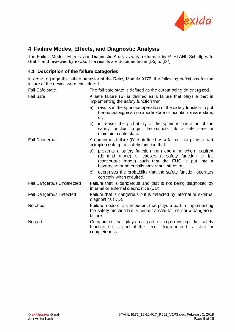
4.1 Description of the failure categories
In order to judge the failure behavior of the Relay Module 9172, the following definitions for the failure of the device were considered.
Fail-Safe state The fail-safe state is defined as the output being de-energized.
Fail Safe A safe failure (S) is defined as a failure that plays a part in implementing the safety function that:
a) results in the spurious operation of the safety function to put the output signals into a safe state or maintain a safe state; or,
b) increases the probability of the spurious operation of the safety function to put the outputs into a safe state or maintain a safe state.
Fail Dangerous A dangerous failure (D) is defined as a failure that plays a part in implementing the safety function that:
a) prevents a safety function from operating when required (demand mode) or causes a safety function to fail (continuous mode) such that the EUC is put into a hazardous or potentially hazardous state; or,
b) decreases the probability that the safety function operates correctly when required.
Fail Dangerous Undetected Failure that is dangerous and that is not being diagnosed by internal or external diagnostics (DU).
Fail Dangerous Detected Failure that is dangerous but is detected by internal or external diagnostics (DD).
No effect Failure mode of a component that plays a part in implementing the safety function but is neither a safe failure nor a dangerous failure.
No part Component that plays no part in implementing the safety function but is part of the circuit diagram and is listed for completeness.

© exida.com GmbH STAHL 9172_13-11-017_R031_V1R3.doc; February 5, 2019 Jan Hettenbach Page 10 of 19
4.2 Methodology – FMEDA, Failure Rates
4.2.1 FMEDA
A Failure Modes and Effects Analysis (FMEA) is a systematic way to identify and evaluate the effects of different component failure modes, to determine what could eliminate or reduce the chance of failure, and to document the system under consideration.
An FMEDA (Failure Mode Effect and Diagnostic Analysis) is an FMEA extension. It combines standard FMEA techniques with extensions to identify online diagnostics techniques and the failure modes relevant to safety instrumented system design. It is a technique recommended to generate failure rates for each important category (safe detected, safe undetected, dangerous detected, dangerous undetected, fail high, fail low) in the safety models. The format for the FMEDA is an extension of the standard FMEA format from MIL STD 1629A, Failure Modes and Effects Analysis.
4.2.2 Failure Rates
The failure rate data used by exida in this FMEDA is from the Electrical and Mechanical Component Reliability Handbook [N2] which was derived using over ten billion unit operational hours of field failure data from multiple sources and failure data from various databases. The rates were chosen in a way that is appropriate for safety integrity level verification calculations. The rates were chosen to match operating stress conditions typical of an industrial field
environment similar to exida Profile 1. It is expected that the actual number of field failures due to random events will be less than the number predicted by these failure rates.
For hardware assessment according to IEC 61508 only random equipment failures are of interest. It is assumed that the equipment has been properly selected for the application and is adequately commissioned such that early life failures (infant mortality) may be excluded from the analysis.
Failures caused by external events however should be considered as random failures. Examples of such failures are loss of power or physical abuse.
The assumption is also made that the equipment is maintained per the requirements of IEC 61508 or IEC 61511 and therefore a preventative maintenance program is in place to replace equipment before the end of its “useful life”.
The user of these numbers is responsible for determining their applicability to any particular environment. Accurate plant specific data may be used for this purpose. If a user has data
collected from a good proof test reporting system such as exida SILStatTM that indicates higher failure rates, the higher numbers shall be used. Some industrial plant sites have high levels of stress. Under those conditions the failure rate data is adjusted to a higher value to account for the specific conditions of the plant.

© exida.com GmbH STAHL 9172_13-11-017_R031_V1R3.doc; February 5, 2019 Jan Hettenbach Page 11 of 19
4.2.3 Assumptions
The following assumptions have been made during the Failure Modes, Effects, and Diagnostic Analysis of the Relay Module 9172.
Failure rates are constant, wear out mechanisms are not included.
Propagation of failures is not relevant.
The device is installed per manufacturer’s instructions.
Sufficient tests are performed prior to shipment to verify the absence of vendor and/or manufacturing defects that prevent proper operation of specified functionality to product specifications or cause operation different from the design analyzed.
The Mean Time To Restoration (MTTR) after a safe failure is 24 hours.
For safety applications only the described configurations of the Relay Module 9172 are considered.
Only one channel of the Relay Module 9172 is part of the FMEDA, both channels in the dual channel configuration are independent of each other.
It is assumed that the relay output is protected against current overload by using a fuse or other limiting devices.

© exida.com GmbH STAHL 9172_13-11-017_R031_V1R3.doc; February 5, 2019 Jan Hettenbach Page 12 of 19
4.3 Results of the assessment
DCD = DD / (DD + DU)
total = SD + SU + DD + DU
MTBF = MTTF + MTTR = (1 / (total + no part + AU)) + 24 h
According to IEC 61508 the architectural constraints of an element must be determined. This can be done by following the 1H approach according to 7.4.4.2 of IEC 61508-2 or the 2H approach according to 7.4.4.3 of IEC 61508-2.
The 1H approach involves calculating the Safe Failure Fraction for the entire element.
The 2H approach involves assessment of the reliability data for the entire element according to 7.4.4.3.3 of IEC 61508-2.
This assessment supports the 1H approach.
According to 3.6.15 of IEC 61508-4, the Safe Failure Fraction is the property of a safety related element that is defined by the ratio of the average failure rates of safe plus dangerous detected failures and safe plus dangerous failures. This ratio is represented by the following equation:
SFF = (ΣλS avg + ΣλDD avg) / (ΣλS avg + ΣλDD avg+ ΣλDU avg )
When the failure rates are based on constant failure rates, as in this analysis, the equation can be simplified to:
SFF = (ΣλS + ΣλDD) / (ΣλS + ΣλDD + ΣλDU )
Where:
λS = Fail Safe
λDD = Fail Dangerous Detected
λDU= Fail Dangerous Undetected
As the Relay Module 9172 is only one part of an element, the architectural constraints should be determined for the entire sensor element.

© exida.com GmbH STAHL 9172_13-11-017_R031_V1R3.doc; February 5, 2019 Jan Hettenbach Page 13 of 19
4.3.1 Results of Relay Module 9172
The FMEDA carried out on the Relay Module 9172 and the assumptions described in section 4.2.3 and 4.3 is leading to the following failure rates:
Table 3: Failure rates Relay Module 9172 [V1] to [V3] 9
exida Profile 1
Failure category Failure rates (in FIT)
Fail Safe Detected (SD) 0
Fail Safe Undetected (SU) 41
Fail Dangerous Detected (DD) 0
Fail Dangerous Undetected (DU) 25
Fail Annunciation Undetected (AU) 0
No effect 20
No part 2
Total failure rate (safety function) 66
Safe failure fraction (SFF ) 10 62%
SIL AC 11 SIL2
9 The failure rates are the worst case results of versions [V1] to [V3].
10 The complete final element subsystem will need to be evaluated to determine the overall Safe Failure Fraction. The
number listed is for reference only. 11
SIL AC (architectural constraints) means that the calculated values are within the range for hardware architectural constraints for the corresponding SIL but does not imply all related IEC 61508 requirements are fulfilled. The SIL AC (architectural constraints) needs to be evaluated on subsystem level.
© exida.com GmbH STAHL 9172_13-11-017_R031_V1R3.doc; February 5, 2019 Jan Hettenbach Page 14 of 19
5 Using the FMEDA Results
The following section describes how to apply the results of the FMEDA.
5.1 Example PFDAVG calculation
It is the responsibility of the Safety Instrumented Function designer to do calculations for the entire SIF. exida recommends the accurate Markov based exSILentia tool for this purpose.
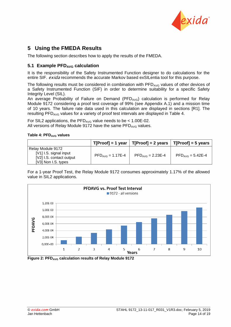
The following results must be considered in combination with PFDAVG values of other devices of a Safety Instrumented Function (SIF) in order to determine suitability for a specific Safety Integrity Level (SIL). An average Probability of Failure on Demand (PFDAVG) calculation is performed for Relay Module 9172 considering a proof test coverage of 99% (see Appendix A.1) and a mission time of 10 years. The failure rate data used in this calculation are displayed in sections [R1]. The resulting PFDAVG values for a variety of proof test intervals are displayed in Table 4.
For SIL2 applications, the PFDAVG value needs to be < 1.00E-02. All versions of Relay Module 9172 have the same PFDAVG values.
Table 4: PFDAVG values
T[Proof] = 1 year T[Proof] = 2 years T[Proof] = 5 years
Relay Module 9172 [V1] I.S. signal input [V2] I.S. contact output [V3] Non I.S. types
PFDAVG = 1.17E-4 PFDAVG = 2.23E-4 PFDAVG = 5.42E-4
For a 1-year Proof Test, the Relay Module 9172 consumes approximately 1.17% of the allowed value in SIL2 applications.
Figure 2: PFDAVG calculation results of Relay Module 9172

© exida.com GmbH STAHL 9172_13-11-017_R031_V1R3.doc; February 5, 2019 Jan Hettenbach Page 15 of 19
6 Terms and Definitions
FIT Failure In Time (1x10⁻⁹ failures per hour)
FMEDA Failure Mode Effect and Diagnostic Analysis
HFT Hardware Fault Tolerance
Low demand mode Mode where the frequency of demands for operation made on a safety-related system is no greater than one per year and no greater than twice the proof test frequency.
PFDAVG Average Probability of Failure on Demand
SFF Safe Failure Fraction, summarizes the fraction of failures, which lead to a safe state and the fraction of failures which will be detected by diagnostic measures and lead to a defined safety action.
SIF Safety Instrumented Function
SIL Safety Integrity Level
SIS
Safety Instrumented System – Implementation of one or more Safety Instrumented Functions. A SIS is composed of any combination of sensor(s), logic solver(s), and final element(s).
PLC Programmable Logic Controller
Type A element “Non-complex” element (all failure modes are well defined); for details see 7.4.4.1.2 of IEC 61508-2.
I.S. Intrinsically Safe
© exida.com GmbH STAHL 9172_13-11-017_R031_V1R3.doc; February 5, 2019 Jan Hettenbach Page 16 of 19
7 Status of the Document
7.1 Liability
exida prepares FMEDA reports based on methods advocated in International standards. Failure
rates are obtained from a collection of industrial databases. exida accepts no liability whatsoever for the use of these numbers or for the correctness of the standards on which the general calculation methods are based.
Due to future potential changes in the standards, best available information and best practices, the current FMEDA results presented in this report may not be fully consistent with results that would be presented for the identical product at some future time. As a leader in the functional
safety market place, exida is actively involved in evolving best practices prior to official release of updated standards so that our reports effectively anticipate any known changes. In addition, most changes are anticipated to be incremental in nature and results reported within the previous three year period should be sufficient for current usage without significant question.
Most products also tend to undergo incremental changes over time. If an exida FMEDA has not been updated within the last three years and the exact results are critical to the SIL verification you may wish to contact the product vendor to verify the current validity of the results.
7.2 Releases
Version History: V1R3: Review and update of reference documents, February 5, 2019
V1R2: Editorial Changes, November 14, 2014
V1R1: Editorial Changes, October 6, 2014
V1R0: Editorial Changes after review; September 29, 2014
V0R1: Initial draft; July 28, 2014
Author: Jan Hettenbach
Review: Andreas Bagusch (R. STAHL Schaltgeräte GmbH); July 28, 2014
Stephan Aschenbrenner (exida); September 25, 2014
Release Status: V1R0 Released to R. STAHL Schaltgeräte GmbH
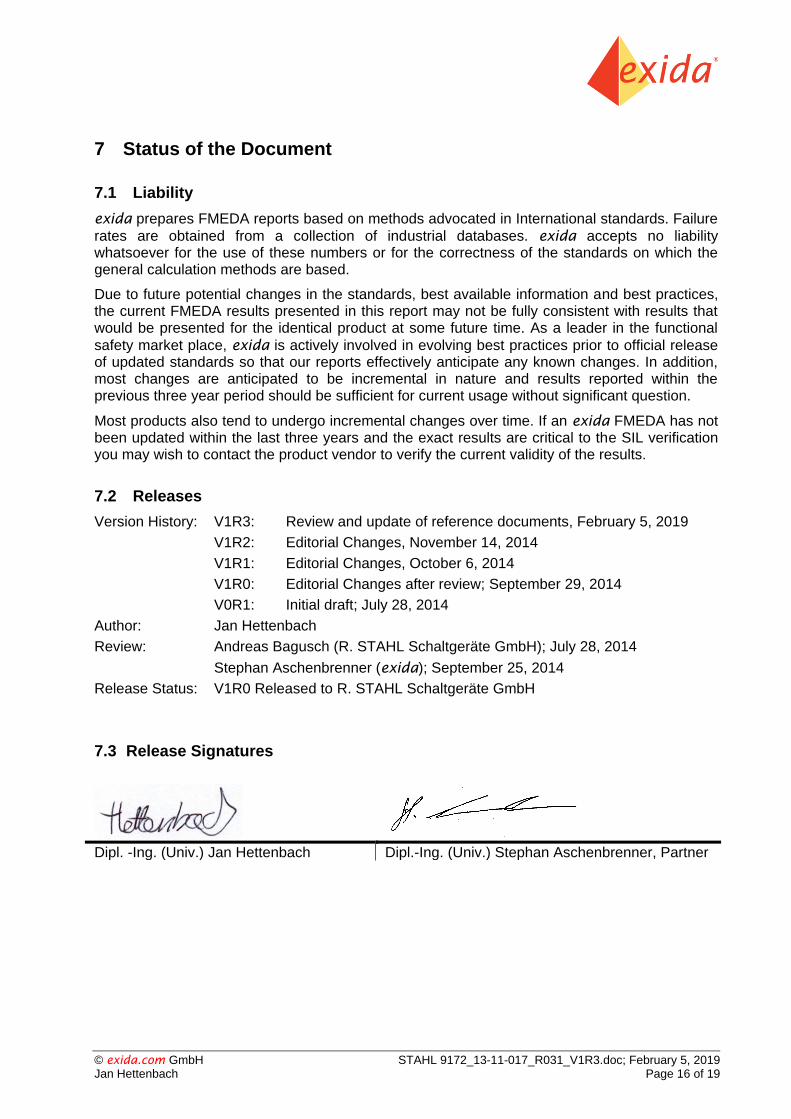
7.3 Release Signatures
Dipl. -Ing. (Univ.) Jan Hettenbach Dipl.-Ing. (Univ.) Stephan Aschenbrenner, Partner
© exida.com GmbH STAHL 9172_13-11-017_R031_V1R3.doc; February 5, 2019 Jan Hettenbach Page 17 of 19
Appendix A: Possibilities to reveal dangerous undetected faults during the proof test
According to section 7.4.5.2 f) of IEC 61508-2 proof tests shall be undertaken to reveal dangerous faults which are undetected by diagnostic tests.
This means that it is necessary to specify how dangerous undetected faults which have been noted during the FMEDA can be detected during proof testing.
Appendix A shall be considered when writing the safety manual as it contains important safety related information.
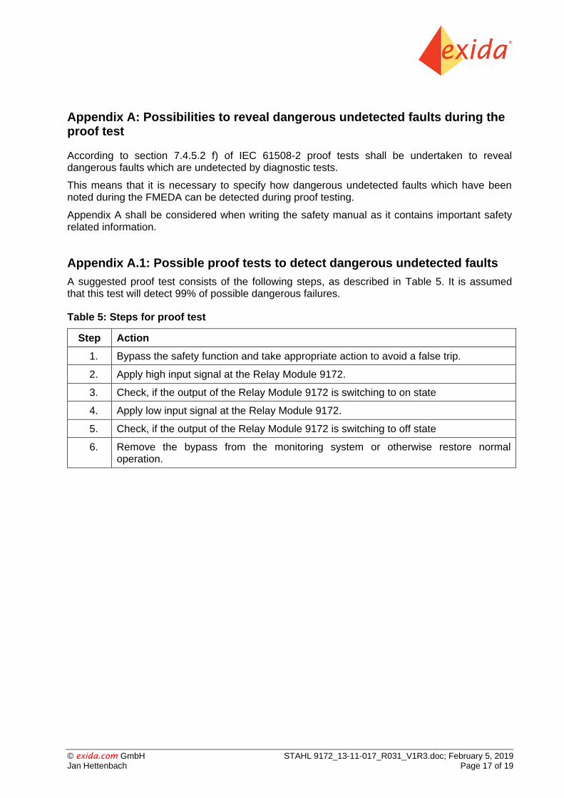
Appendix A.1: Possible proof tests to detect dangerous undetected faults
A suggested proof test consists of the following steps, as described in Table 5. It is assumed that this test will detect 99% of possible dangerous failures.
Table 5: Steps for proof test
Step Action
1. Bypass the safety function and take appropriate action to avoid a false trip.
2. Apply high input signal at the Relay Module 9172.
3. Check, if the output of the Relay Module 9172 is switching to on state
4. Apply low input signal at the Relay Module 9172.
5. Check, if the output of the Relay Module 9172 is switching to off state
6. Remove the bypass from the monitoring system or otherwise restore normal operation.

© exida.com GmbH STAHL 9172_13-11-017_R031_V1R3.doc; February 5, 2019 Jan Hettenbach Page 18 of 19
Appendix B: Impact of lifetime of critical components on the failure rate
According to section 7.4.9.5 of IEC 61508-2, a useful lifetime, based on experience, should be assumed.
Although a constant failure rate is assumed by the probabilistic estimation method (see section 4.2.3) this only applies provided that the useful lifetime 12 of components is not exceeded. Beyond their useful lifetime, the result of the probabilistic calculation method is meaningless, as the probability of failure significantly increases with time. The useful lifetime is highly dependent on the component itself and its operating conditions – temperature in particular (for example, electrolyte capacitors can be very sensitive).
This assumption of a constant failure rate is based on the bathtub curve. Therefore it is obvious that the PFDAVG calculation is only valid for components which have this constant domain and that the validity of the calculation is limited to the useful lifetime of each component.
It is assumed that early failures are detected to a huge percentage during the installation period and therefore the assumption of a constant failure rate during the useful lifetime is valid.
Table 6 shows which components with reduced useful lifetime are contributing to the dangerous undetected failure rate and therefore to the PFDAVG calculation and what their estimated useful lifetime is.
Table 6: Useful lifetime of components with reduced useful lifetime contributing to λdu
Type Name Useful life time
Relay, contact force >20cN K01A (K51A) 100.000 switching cycles
When plant experience indicates a shorter useful lifetime than indicated in this appendix, the number based on plant experience should be used.
12
Useful lifetime is a reliability engineering term that describes the operational time interval where the failure rate of a device is relatively constant. It is not a term which covers product obsolescence, warranty, or other commercial issues.
© exida.com GmbH STAHL 9172_13-11-017_R031_V1R3.doc; February 5, 2019 Jan Hettenbach Page 19 of 19
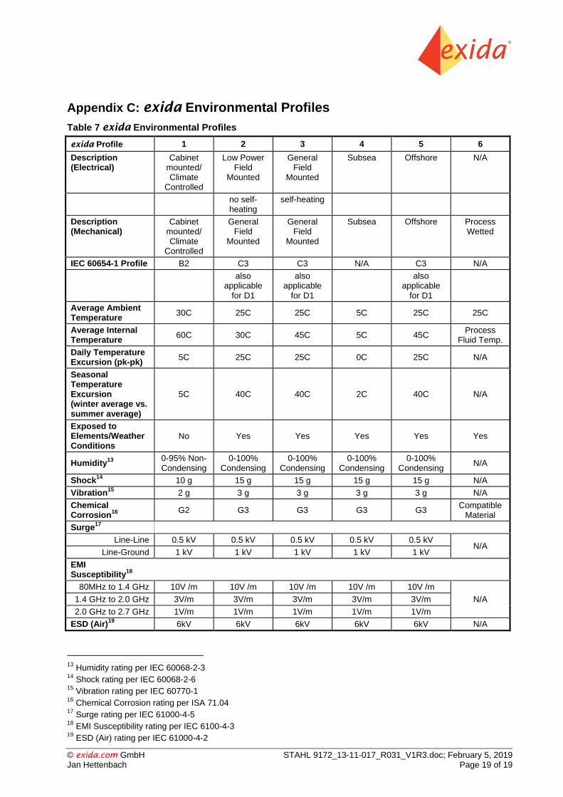
Appendix C: exida Environmental Profiles
Table 7 exida Environmental Profiles
exida Profile 1 2 3 4 5 6
Description (Electrical)
Cabinet mounted/ Climate
Controlled
Low Power Field
Mounted
General Field
Mounted
Subsea Offshore N/A
no self-heating
self-heating
Description (Mechanical)
Cabinet mounted/ Climate
Controlled
General Field
Mounted
General Field
Mounted
Subsea Offshore Process Wetted
IEC 60654-1 Profile B2 C3 C3 N/A C3 N/A
also applicable
for D1
also applicable
for D1
also applicable
for D1
Average Ambient Temperature
30C 25C 25C 5C 25C 25C
Average Internal Temperature
60C 30C 45C 5C 45C Process
Fluid Temp.
Daily Temperature Excursion (pk-pk)
5C 25C 25C 0C 25C N/A
Seasonal Temperature Excursion (winter average vs. summer average)
5C 40C 40C 2C 40C N/A
Exposed to Elements/Weather Conditions
No Yes Yes Yes Yes Yes
Humidity13
0-95% Non-Condensing
0-100% Condensing
0-100% Condensing
0-100% Condensing
0-100% Condensing
N/A
Shock14
10 g 15 g 15 g 15 g 15 g N/A
Vibration15
2 g 3 g 3 g 3 g 3 g N/A
Chemical Corrosion
16
G2 G3 G3 G3 G3 Compatible
Material
Surge17
Line-Line 0.5 kV 0.5 kV 0.5 kV 0.5 kV 0.5 kV N/A
Line-Ground 1 kV 1 kV 1 kV 1 kV 1 kV
EMI Susceptibility
18
80MHz to 1.4 GHz 10V /m 10V /m 10V /m 10V /m 10V /m
N/A 1.4 GHz to 2.0 GHz 3V/m 3V/m 3V/m 3V/m 3V/m
2.0 GHz to 2.7 GHz 1V/m 1V/m 1V/m 1V/m 1V/m
ESD (Air)19
6kV 6kV 6kV 6kV 6kV N/A
13
Humidity rating per IEC 60068-2-3 14
Shock rating per IEC 60068-2-6 15
Vibration rating per IEC 60770-1 16
Chemical Corrosion rating per ISA 71.04 17
Surge rating per IEC 61000-4-5 18
EMI Susceptibility rating per IEC 6100-4-3 19
ESD (Air) rating per IEC 61000-4-2