Failure mechanisms and stability analysis of deep-seated ...
227
Failure mechanisms and stability analysis of deep-seated landslides in the northwestern Rift escarpment, Ethiopia Dissertation submitted in partial fulfilment of the requirements for the degree of Doctor rerum naturalium (Dr. rer. nat.) to the Faculty of Geosciences Ruhr-Universität Bochum by Tesfay Kiros Mebrahtu Supervisors Prof. Dr. Stefan Wohnlich Prof. Dr.-Ing. Michael Alber Bochum 2020
-
Upload
khangminh22 -
Category
Documents
-
view
2 -
download
0
Transcript of Failure mechanisms and stability analysis of deep-seated ...

Failure mechanisms and stability analysis of
deep-seated landslides in the northwestern Rift
escarpment, Ethiopia
Dissertation
submitted in partial fulfilment of the requirements
for the degree of Doctor rerum naturalium (Dr. rer. nat.)
to the
Faculty of Geosciences
Ruhr-Universität Bochum
by
Tesfay Kiros Mebrahtu
Supervisors
Prof. Dr. Stefan Wohnlich
Prof. Dr.-Ing. Michael Alber
Bochum 2020


Dedicated to my parents.

Eidesstattliche Erklärung
Ich versichere an Eides statt, dass ich die eingereichte Dissertation selbstständig
und ohne unzulässige fremde Hilfe verfasst, andere als die in ihr angegebene
Literatur nicht benutzt und dass ich alle ganz oder annähernd übernommenen
Textstellen sowie verwendete Grafiken, Tabellen und Auswertungsprogramme
kenntlich gemacht habe. Außerdem versichere ich, dass die vorgelegte
elektronische mit der schriftlichen Version der Dissertation übereinstimmt und
die Abhandlung in dieser oder ähnlicher Form noch nicht anderweitig als
Promotionsleistung vorgelegt und bewertet wurde.
Bochum, 26.10.2020
Ort, Datum Unterschrift

Abstract
Landslides and ground failures are among the common geo-environmental hazards
in many of the tectonically active hilly and mountainous terrains of Ethiopia. The
study area is located in the central-western highlands of Ethiopia forming a
spectacular escarpment along the margins of the southwestern Afar depression
that is tectonically active since the beginning of Cenozoic Era. Owing to this, the
Debre Sina area and its surrounding are a potentially unstable environment in
terms of slope failure leading to landslides and mass movements. Deep-seated
landslides are common in the Debre Sina area where the geo-structural setting
plays a key role in controlling the geometry of the failure surface and its
displacement. Particularly, the Yizaba Wein, Shotel Amba, Nib Amba, and Wanza
Beret localities are repeatedly affected by deep-seated landslides. Despite that,
urban and rural development is currently active in almost the entire area. The
main objective of this study is to understand the processes leading to initiation and
propagation of slope failure, the influencing factors, and the failure mechanisms.
The study was carried out using a multidisciplinary approach based on geological,
morpho-tectonic analysis, geomorphological, hydrogeological, hydrogeochemical,
isotopic, geophysical (seismic refraction and vertical electrical sounding) and
geotechnical (kinematic analysis and numerical modelling) investigations.
According to the results, the deep-seated landslides in the study area are strongly
controlled by geological structures coinciding with the regional trend of the rift
margin faults. The geophysical data indicates that the area is covered by
unconsolidated sediments and highly decomposed and weak volcanic rocks which
are susceptible to sliding when they get moist. The slip surface generally coincides
with the presence of highly fractured and saturated rocks. The results of the
hydrogeochemical and stable isotopes illustrate that the main causes of the
landslide are the steep topography and the pressure formed during precipitation,
which leads to an increased weight of the loose and weathered materials. The
heterogeneity of the geological materials and the presence of impermeable layers
embodied within the highly permeable volcanic rocks can result in the build-up of
hydrostatic pressure at their interface, which can trigger landslides. Intense

fracturing in the tilted basalt and ignimbrite beds can also accelerate infiltration
of water, resulting to the build-up of high hydrostatic pressure causing low
effective normal stress in the rock mass, giving rise to landslides. The numerical
stability analysis indicates that the slope stability of landslide prone hills in the
study area strongly depends on the saturation conditions and the seismic load. In
general, an integrated analysis of all acquired data indicates that the deep-seated
landslides are controlled by different predisposing factors: tectonic uplift;
geological-structural setting; complex morphology of the slope and its high relief
energy; presence of closely spaced normal fault segments with steep slope angles;
and deepening action of the streams (active erosion and gullying). The findings of
this study can be used to understand mechanisms of deep-seated landslides in
similar morphological, geological and tectonic settings.

Kurzfassung
Erdrutsche gehören zu den häufigsten Naturgefahren im tektonisch aktiven
Bergland Äthiopiens. Das Untersuchungsgebiet befindet sich im zentralen
westlichen Hochland Äthiopiens mit spektakulären Steilhängen entlang den
Rändern der südwestlichen Afar-Senke, die seit Beginn des Känozoikums
tektonisch aktiv ist. Das Gebiet rund um Debre Sina ist daher potentiell instabil
und für Erdrutsche anfällig. Besonders tiefsitzende Massenbewegungen sind im
Debre Sina Gebiet häufig, da dort die geo-strukturellen Gegebenheiten eine
Schlüsselrolle in der Geometrie der Rutschfläche und der Hangbewegung spielen.
Gerade die Gebiete Yizaba Wein, Shotel Amba, Nib Amba und Wanza Beret sind
regelmäßig durch tiefsitzende Erdrutsche nach Starkregen betroffen. Dennoch
schreitet die städtische und ländliche Entwicklung im gesamten Gebiet stetig
voran. Das Hauptziel der vorliegenden Arbeit ist das Verständnis der Prozesse, die
zur Auslösung und dem Fortschreiten des Versagensprozesses führen, der
beeinflussenden Faktoren und der Versagensmechanik. Die Studie verwendet
einen interdisziplinären Ansatz bestehend aus einer geologischen und morpho-
tektonischen Analyse, sowie geomorphologischen, hydrogeologischen,
hydrogeochemischen, isotopischen, geophysikalischen (Refraktionsseismik und
Vertikale Elektrische Sondierung) sowie geotechnischen (kinematische Analyse
und numerische Modellierung) Untersuchungen.
Die Ergebnisse der Studie zeigen, dass die tiefsitzenden Erdrutsche im
Untersuchungsgebiet maßgeblich von den geologischen Strukturen geprägt sind,
die dem regionalen Trend der Verwerfungen am westlichen Rand des Rift folgen.
Aus den geologischen und geophysikalischen Untersuchungen lässt sich ableiten,
dass in dem Gebiet von unkonsolidierten Sedimenten und stark zersetzten und
weichen vulkanischen Gesteine vorherrschen, welche unter Wassereinfluss
Rutschbewegungen begünstigen. Allgemein stimmt die Rutschfläche mit der
Anwesenheit von stark geklüfteten und gesättigten Gesteinen überein. Die
Ergebnisse der hydrogeochemischen und stabilen Isotope zeigen, dass die
Hauptursachen für den Erdrutsch die steile Topographie und der während der
Ausfällung gebildete Druck sind, der zu einem erhöhten Gewicht des lockeren und

verwitterten Materials führt. Die Heterogenität der geologischen Materialien und
das Vorhandensein undurchlässiger Schichten, die in den hochdurchlässigen
vulkanischen Gesteinen verankert sind, können zum Aufbau von hydrostatischem
Druck an deren Grenzfläche führen, was Erdrutsche auslösen kann. Intensive
Brüche in den geneigten Basalt- und Ignimbritschichten können auch die
Infiltration von Wasser beschleunigen, was zum Aufbau eines hohen
hydrostatischen Drucks führt, der eine niedrige effektive Normalspannung in der
Gesteinsmasse verursacht, was zu Erdrutschen führt. Die numerische
Stabilitätsanalyse zeigt, dass die Hangstabilität im Untersuchungsgebiet stark
von der Sättigung und der seismischen Belastung abhängt. Ganz allgemein zeigt
eine zusammenfassende Analyse aller gesammelten Daten, dass tiefsitzende
Erdrutsche durch unterschiedliche Vorbedingungen kontrolliert werden:
tektonische Hebung; geologische-struktur Rahmenbedingungen; komplexe
Morphologie der Hänge und ihre hohe Relieffenergie; nahe beieinanderliegende
abschiebende Segmente mit steilen Hangneigungen; Vertiefung der Flüsse durch
aktive Erosion. Somit erweitern die Ergebnisse dieser Studie das Verständnis
tiefsitzender Erdrutsche in ähnlichen morphologischen, geologischen und
tektonischen Gebieten.

Acknowledgements
It is a pleasure to express my gratitude to those who have contributed to the
completion of this thesis. First of all, I am very thankful for the German Academic
Exchange Services (DAAD) for providing me the opportunity to pursue my PhD
study in Germany and its financial assistance.
I would like to express my deepest gratitude to Prof. Dr. Stefan Wohnlich for
providing me an opportunity to conduct doctoral research in his group as well as
for the constant scientific support, encouragement and kind advice he has provided
throughout my time as his student. Throughout my work, his door was always
opened to me when I asked him for advice. So, thank you so much Professor for
your continuous support during the whole journey.
I would also like to extend my gratitude to Prof. Dr.-Ing. Michael Alber for his
continuous scientific contributions to this PhD research work and all his guidance
and kind support throughout the project. Your knowledgeable and constructive
insights, encouragement and your always open door is highly appreciated.
I am thankful to PD Dr. Andre Banning for his valuable scientific reviews of my
research outputs and his continuous support. Thanks a lot, Andre. I am also
grateful to Dr. Thomas Heinze for his good encouragements, discussions, critically
read about my manuscripts and providing helpful comments. It is a joy to work
with this young scientist.
I have special thanks to Dr. Bedru Hussien for sharing me his research skill and
invaluable assistance and helped me during the fieldwork in Ethiopia. My sincere
thanks is extended to Dr. Ermias Hagos for his constant encouragement, generous
reviewing some of the sections in this thesis and insightful comments. Many
thanks also goes to Dr. Tesfaye Asresahagne (General Manager of Geomatrix Plc)
for providing me field logistics during the seismic refraction survey.
I would like to thank the Ruhr University Bochum Research School (RUB-RS), not
only for providing the funding which allowed me to undertake fieldwork, but also
for giving me the opportunity to attend international conferences and meet so

many interesting people. I am also grateful to the kind support and friendly from
Dr. Ursula Justus and Dr. Sarah Gemicioglu and other staffs of the RUB-RS. I
would like to thank the Wilhelm and Günter Esser Foundation for granting me a
scholarship to complete my dissertation.
I am thankful to Dr. Ferdinand Stöckhert, Claudia Brajer, Cedric Solibilda,
Kirsten Bartmann for their technical help and keeping a nice working atmosphere
in the rock mechanics laboratory of the RUB. Many thanks to the technical staffs
of Hydrogeology group, particularly Richard Nicolaus and Oliver Schübbe for their
patience and great effort they put to analyze the chemistry of water samples in the
hydrochemistry laboratory of the RUB. My special thanks to Isodetect
(Environmental Monitoring) in Munich and the Department of Materials and
Earth Sciences at the Technical University of Darmstadt for analysing the isotope
data used in this study.
I would like to thank all my fellow PhD students and staffs of the Applied Geology
Department for keeping a nice and friendly working atmosphere which is a key to
finish the journey. The cheerful and learning time with all other colleagues at the
RUB will stay in my heart forever.
Thanks are due to the Geological Survey of Ethiopia (GSE), National Meteorology
Agency of Ethiopia (NMA), Ethiopian Mapping Agency (EMA), Ethiopian Ministry
of Mines and Petroleum (MoMP) and Ethiopian Ministry of Water and Energy
(MoWE) for their generous provision of secondary data and support letters that are
enormously important for this research project.
Last but not least, a special word of thanks to my family and friends who kept in
touch with me all the time and encouraged me to finish the thesis. I am indebted
to them for their help. Thank you to all whose names are not mentioned who
supported me in any way during this study.
Above all, I give glory to God for his blessings, protection and love.

“If you can’t fly then run, if you can’t run then
walk, if you can’t walk then crawl, but whatever
you do you have to keep moving forward.”
Dr. Martin Luther King Jr.

Table of Contents
I
Table of Contents
Table of Contents ....................................................................................................... I
List of Figures ......................................................................................................... VI
List of Tables .......................................................................................................... XII
List of Acronyms ................................................................................................... XIII
List of Symbols ...................................................................................................... XVI
Chapter 1 ................................................................................................................... 1
1 Introduction ........................................................................................................ 1
1.1 Background .................................................................................................. 1
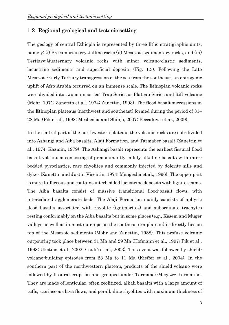
1.2 Regional geological and tectonic setting ..................................................... 5
1.3 Landslide types and their failure mechanisms ........................................ 12
1.3.1 Slides .................................................................................................... 13
1.3.2 Falls ..................................................................................................... 13
1.3.3 Topples ................................................................................................. 14
1.3.4 Lateral spreads .................................................................................... 14
1.3.5 Flows .................................................................................................... 15
1.4 Problem statement ..................................................................................... 17
1.5 Research objectives .................................................................................... 19
1.5.1 Main objective ...................................................................................... 19
1.5.2 Specific objectives ................................................................................ 20
Table of Contents
II
1.6 Summary of methodology .......................................................................... 20
1.7 Structure of the Thesis .............................................................................. 23
Chapter 2 ................................................................................................................. 25
2 Predisposing and triggering factors of large-scale landslides in Debre Sina
area, central Ethiopian highlands .......................................................................... 25
Abstract ................................................................................................................ 25
2.1 Introduction ................................................................................................ 26
2.2 The study area ........................................................................................... 27
2.3 Materials and methods .............................................................................. 29
2.4 Results ........................................................................................................ 31
2.4.1 Geology and geomorphology of the study area ................................... 31
2.4.2 Description, typology, and distribution of landslides ........................ 38
2.5 Discussion ................................................................................................... 45
2.5.1 Lithology and structure ....................................................................... 45
2.5.2 Elevation, slope angle, and aspect ...................................................... 49
2.5.3 Rainfall ................................................................................................ 50
2.5.4 Earthquakes ........................................................................................ 51
2.6 Conclusions ................................................................................................ 54
Chapter 3 ................................................................................................................. 56
3 Tectonic conditioning revealed by seismic refraction facilitates deep-seated
landslides in the western escarpment of the Main Ethiopian Rift ....................... 56
Abstract ................................................................................................................ 56

Table of Contents
III
3.1 Introduction ................................................................................................ 58
3.2 The study area ........................................................................................... 60
3.3 Materials and methods .............................................................................. 61
3.3.1 Instrumentation and field procedures ................................................ 62
3.3.2 Data acquisition, processing, and presentation ................................. 64
3.4 Results ........................................................................................................ 68
3.4.1 Geology and geomorphology of the study area ................................... 68
3.4.2 Profile one and two (L1–L2) ................................................................ 72
3.4.3 Profile 3 (L3) ........................................................................................ 76
3.4.4 Kinematic analysis of slope failure ..................................................... 77
3.5 Discussion ................................................................................................... 82
3.6 Conclusions ................................................................................................ 89
Chapter 4 ................................................................................................................. 92
4 The effect of hydrogeological and hydrochemical dynamics on landslide
triggering in the central highlands of Ethiopia ..................................................... 92
Abstract ................................................................................................................ 92
4.1 Introduction ................................................................................................ 94
4.2 The study area ........................................................................................... 96
4.2.1 Geological setting ................................................................................ 99
4.3 Materials and methods ............................................................................ 102
4.3.1 Water sampling and analytical methods .......................................... 102

Table of Contents
IV
4.3.2 Geophysical survey ............................................................................ 104
4.4 Results and discussion ............................................................................. 107
4.4.1 Aquifer system and groundwater flow ............................................. 107
4.4.2 Hydrogeochemical facies ................................................................... 110
4.4.3 Mechanisms controlling water chemistry ........................................ 113
4.4.4 The implications of groundwater dynamics with landslides ........... 114
4.4.5 Evidence from isotopic signatures .................................................... 118
4.4.6 Vertical Electrical Sounding ............................................................. 122
4.5 Conclusions .............................................................................................. 128
Chapter 5 ............................................................................................................... 130
5 Slope stability analysis of deep-seated landslides using Limit Equilibrium and
Finite Element methods under static and seismic load in Debre Sina area,
Ethiopia……………………………………………………………………………………130
Abstract .............................................................................................................. 130
5.1 Introduction .............................................................................................. 131
5.2 Geology of the area ................................................................................... 134
5.3 Methods and materials ............................................................................ 137
5.3.1 Model generation ............................................................................... 138
5.3.2 Limit equilibrium analysis ................................................................ 139
5.3.3 Finite element analysis ..................................................................... 141
5.4 Results and discussion ............................................................................. 145
5.4.1 Limit equilibrium analysis ................................................................ 145

Table of Contents
V
5.4.2 Finite element analysis ..................................................................... 148
5.5 Conclusions .............................................................................................. 155
Chapter 6 ............................................................................................................... 158
6 Summary and future research perspectives .................................................. 158
6.1 Summary .................................................................................................. 158
6.2 Future research perspectives .................................................................. 163
Declaration of authorship ..................................................................................... 165
References ............................................................................................................. 167
Appendix ................................................................................................................ 189

List of Figures
VI
List of Figures
Figure 1.1: (a) Global landslide susceptibility map computed using slope, geology,
fault zones, road networks, and forest loss (Stanley and Kirschbaum, 2017); (b)
Global Landslide Catalog (2007–2016) showing the distribution of landslide
fatalities (Kirschbaum et al., 2015b). ....................................................................... 2
Figure 1.2: Landslide distribution of Ethiopia (modified from Woldearegay, 2013).
................................................................................................................................... 4
Figure 1.3: Stratigraphy of the Afar region (modified from Varnet, 1978 and
Beyene and Abdelsalam, 2005). ................................................................................ 7
Figure 1.4: Schematic geological cross sections across the western and southern
Afar margins (modified from Corti et al., 2015). The location of the cross-section
line shown in Fig. 1.5. ............................................................................................... 8
Figure 1.5: Digital elevation map of the Afar Region showing the main structural
divisions (modified from http:www.see.leeds.ac.uk/afar). ..................................... 10
Figure 1.6: 3D view of the Afar depression and the west and east flanking plateaus
(source: http://en.wikipedia.org/wiki/Image:AfarDrape.jpg). ................................ 11
Figure 1.7: Landslide classification based on the type of movement and material (Varnes,
1978 and Cruden and Varnes, 1996). ............................................................................. 16
Figure 2.1: Location map of the study area…………………………………………….28
Figure 2.2: Geological map of the study area. ....................................................... 33
Figure 2.3: Elevation map of the study area. ......................................................... 35
Figure 2.4: Slope angle map of the study area. ..................................................... 36
Figure 2.5: Slope aspect map of the study area. .................................................... 37
Figure 2.6: Landslide inventory and morphostructural map of the study area. .. 39

List of Figures
VII
Figure 2.7: (a) Translational slide occurred in 2005, (b) roto-translational rock slide
and rockfalls, (c) Yizaba Wein and Shotel Amba convex-concave landslides and (d)
rotational slide and earth flow dipping downslope towards Dem Aytemashy river.
................................................................................................................................. 40
Figure 2.8: (a) Debris flow demolished agricultural land in Nib Amba, (b) rock slide
in Nib Amba, (c) deep-seated rotational slides form a pond at the lower part of the
slide zone and (d) earth flow demolished farmland. .............................................. 42
Figure 2.9: (a, b) Earth slides around Nech Amba area occurred on May 6, 2016,
(c) pre-existing landslide scars and active landslides in the gorge of the Majete
river and (d) a quasi-rotational slide widening retrogressively. ........................... 43
Figure 2.10: (a) Photographs showing rock slides around Armaniya along the
asphalt roadside, (b) earth slides, (c) tension cracks in a black cotton soil at Shola
Meda, (d) asphalt road collapsed along Debre Sina and Armaniya. ..................... 45
Figure 2.11: Stereographic projection of joints/fractures orientation data: (a) rose
diagram showing strike direction, (b) rose diagram showing dip direction, (c) plots
of poles and (d) pole density contour diagram. ...................................................... 46
Figure 2.12: Lineament map of the study area. .................................................... 48
Figure 2.13: Rainfall data from the Debre Sina station from 1974 to 2016 compared
with landslide events. ............................................................................................. 51
Figure 2.14: Recorded earthquakes in the East African region from 1842 to 2011
(source: EAGLE data). ............................................................................................ 53
Figure 3.1: Location map of the study area…………………………………………….61
Figure 3.2: The layout of the seismic refraction survey. ....................................... 64
Figure 3.3: Time-distance curve along profile one and two (L1–L2) that black line
is the fit. ................................................................................................................... 67

List of Figures
VIII
Figure 3.4: Time distance curve along profile three (L3) that black line is the fit.
................................................................................................................................. 67
Figure 3.5: Geological and geomorphological map of the study area. ................... 70
Figure 3.6: Panoramic view of the main Yizaba Wein landslide and surroundings
from the east located in north direction of Debre Sina area. ................................ 71
Figure 3.7: Typical landslides in the study area: (a) translational slides in
porphyritic-agglomeratic basalt and seismic refraction line L1–L2 location, (b)
rotational slides on colluvial deposit and volcanic ash/tuff, (c) rock slides in
porphyritic basalt and seismic refraction line L3 location, (d) earth slide in clay soil
and colluvial deposit. .............................................................................................. 74
Figure 3.8: Geological cross section along selected line A–B. ............................... 74
Figure 3.9: Seismic refraction tomography 2D P-wave velocity cross-section along
profile L1–L2. .......................................................................................................... 75
Figure 3.10: Seismic refraction tomography 2D P-wave velocity cross-section along
profile L3. ................................................................................................................ 77
Figure 3.11: The main Yizaba Wein landslide located in north direction of Debre
Sina town: fault 1–green (NNE–SSW), fault 2–blue (NNW–SSE) and fault 3–
purple (WSW–ENE). ............................................................................................... 78
Figure 3.12: Stereonet of planar sliding kinematic analysis. ............................... 80
Figure 3.13: Stereonet of wedge sliding kinematic analysis. ................................ 81
Figure 3.14: Rose diagram showing strike direction. ............................................ 82
Figure 3.15: Delta-t-V inversion along profile one and two (L1–L2). ................... 84
Figure 3.16: Delta-t-V inversion along profile three (L3). ..................................... 86
Figure 4.1: Location map of the study area…………………………………………….97

List of Figures
IX
Figure 4.2: (a) Panoramic view of the main Yizaba and Shotel Amba landslides
from east, with examples of characteristic geodynamic features within the main
landslide body and its surroundings: (b) rotational slide, (c) rock slide, (d)
debris/earth slide, (e) debris flow, (f) earth flow, (g) translational slide occurred in
2005 and (g) large-scale sliding. ............................................................................. 99
Figure 4.3: Geological map of the study area (modified from Mebrahtu et al.,
2020a). ................................................................................................................... 101
Figure 4.4: Groundwater level map and groundwater flow directions based on
spring and river positions. .................................................................................... 108
Figure 4.5: Piper diagram showing compositions of different water types in the
study area. ............................................................................................................. 111
Figure 4.6: A schematic cross section (W–E), showing the hydrogeological
conceptual model of the Debre Sina landslide. The location of the cross section and
its view direction is shown in Fig. 4.3. ................................................................. 112
Figure 4.7: Gibbs diagrams for (a) cations and (b) anions indicating rock-water
interaction as the major process regulating the chemistry of the groundwater in
the study area. ....................................................................................................... 113
Figure 4.8: Categorization of the water samples resulting from a preliminary
hierarchy cluster analysis (HCA) based on major ions chemistry using the complete
linkage rule and Euclidean distances. ................................................................. 115
Figure 4.9: Pictures of typical landslide localities in the Debre Sina area: (a)
emerging springs in ignimbrite-volcanic ash/tuff, (b) spring water at the contact of
the top layer (colluvium) and underlying altered tuff, (c) seepage spring at the
highly fractured ignimbrite, (d) spring water outflows from the bottom of the
landslide and (e) ponded spring water at the toe of the landslide. ..................... 117
Figure 4.10: (a) Cross plot of δ18O versus δ2H of the water samples with the Addis
Ababa LMWL and the GMWL, (b) isotopic altitude effect of precipitation of the

List of Figures
X
study area and (c) cross plot of 18O versus electrical conductivity (EC) of the study
area. ....................................................................................................................... 120
Figure 4.11: Mean monthly rainfall of the area for the last 43 years (1974 to 2016)
and mean monthly rainfall for the years 2005, 2006, 2007, 2014 and 2016 for the
Debre Sina area. .................................................................................................... 121
Figure 4.12: (a) Geoelectrical section and (b) apparent pseudo-depth section along
profile line–1. ......................................................................................................... 124
Figure 4.13: (a) Geoelectrical section and (b) apparent pseudo-depth section along
profile line–2. ......................................................................................................... 125
Figure 4.14: (a) Geoelectrical section and (b) apparent pseudo-depth section along
profile line–3. ......................................................................................................... 127
Figure 5.1: Geological map of the study area (modified from Mebrahtu et al.,
2020a)………………………………………………………………………………………135
Figure 5.2: Panoramic view of the main Yizaba and Shotel Amba landslides from
east with examples of characteristic geodynamic features within the main
landslide body and its surroundings (modified from Mebrahtu et al., 2021): (a)
rotational slide, (b) rock slide, (c) debris/earth slide, (d) debris flow, (e) earth flow,
and (f) a quasi-rotational slide widening retrogressively with ponded spring water
at the toe of the Wanza Beret landslide. .............................................................. 136
Figure 5.3: Specimens prepared and tested under uniaxial, triaxial, and tensile
loading. .................................................................................................................. 138
Figure 5.4: (a) Slope cross-section and (b) discretized RS2 model of slope section
along the Shotel Amba section. ............................................................................ 144
Figure 5.5: (a) Slope cross-section and (b) discretized RS2 model of slope section
along the Yizaba section. ...................................................................................... 144
Figure 5.6: (a) Slope cross-section and (b) discretized RS2 model of slope section
along the Nib Amba section. ................................................................................. 145

List of Figures
XI
Figure 5.7: (a) Slope cross-section and (b) discretized RS2 model of slope section
along the Wanza Beret section. ............................................................................ 145
Figure 5.8: 2D cross-section result from slide along the Shotel Amba section... 147
Figure 5.9: 2D cross-section result from slide along the Yizaba section. ........... 147
Figure 5.10: 2D cross-section result from slide along the Wanza Beret section. 148
Figure 5.11: (a) Finite element analysis for shear strain and (b) finite element
analysis for total displacement with maximum total displacement of 225 m along
the Shotel Amba section. ...................................................................................... 149
Figure 5.12: (a) Finite element analysis for shear strain and (b) finite element
analysis for total displacement with maximum total displacement of 36.1 m along
the Yizaba section. ................................................................................................ 152
Figure 5.13: (a) Finite element analysis for shear strain and (b) finite element
analysis for total displacement with maximum total displacement of 1.3 m along
the Nib Amba section. ........................................................................................... 153
Figure 5.14: (a) Finite element analysis for shear strain and (b) finite element
analysis for total displacement with maximum total displacement of 1.9 m along
the Wanza Beret section. ...................................................................................... 154

List of Tables
XII
List of Tables
Table 1.1: Landslide classification based on types of material and mode of
movement (Cruden and Varnes, 1996). .................................................................. 12
Table 3.1: Parameters of seismic refraction used during fieldwork………………...64
Table 3.2: Kinematic analysis of planar and wedge failures. ............................... 81
Table 3.3: Classification of the various subsurface units on the basis of their
compressional velocities. ......................................................................................... 87
Table 4.1: Hydrochemical and isotope data of sampled groundwater and surface
water in the Debre Sina area. SP spring; R river; Ionic concentrations are
measured in mg/L………………………………………………………………………...105
Table 5.1: Material parameters for rock used in LE and FE models………………142
Table 5.2: Geomechanical parameters used for faults. ....................................... 143
Table 5.3: Calculated FS using LE and FE methods without horizontal seismic
coefficient (h= 0). ................................................................................................. 146
Table 5.4: Calculated FS using LE and FE with horizontal seismic coefficient (h=
0.2 and 0.3). ........................................................................................................... 151

List of Acronyms
XIII
List of Acronyms
AAS Atomic Absorption Spectrometry
AGC Automatic Gain Control
BED Boundary Element Method
BSM Bishop’s Simplified Method
BTS Brazilian Tensile Strength
CMER Central Main Ethiopian Rift
CMP Common Mid Point
DAAD German Academic Exchange Service
DFG German Research Foundation
EARS East African Rift System
EAGLE Ethiopia-Afar Geoscientific Lithospheric Experiment
EBC Ethiopian Broadcasting Corporation
EBCS Ethiopian Building Code Standard
EC Electrical Conductivity
EIGS Ethiopian Institute of Geological Surveys
EMA Ethiopian Mapping Agency
ETM+ Enhanced Thematic Mapper Plus
DEM Digital Elevation Model
FDM Finite Difference Method
FE Finite Element
FEM Finite Element Method
FS Factor of Safety
GIS Geographic Information System
GISP Greenland Ice Sheet Precipitation
GMWL Global Meteoric Water Line
GNIP Global Network of Isotopes in Precipitation
GSE Geological Survey of Ethiopia
GSI Geological Strength Index
HCA Hierarchical Cluster Analysis
IAEA International Atomic Energy Agency

List of Acronyms
XIV
IAEG International Association of Engineering Geology
ISRM International Society for Rock Mechanics
JSM Janbu’s Simplified Method
km kilometre
LE Limit Equilibrium
LEM Limit Equilibrium Methods
LMWL Local Meteoric Water Line
mg/L Milligram per Liter
m/s meter per second
ms milliseconds
mm millimeter
MER Main Ethiopian Rift
MoMP Ministry of Mines and Petroleum, Ethiopia
MoWE Ministry of Water and Energy, Ethiopia
MPM Morgenstern-Price Method
NMA National Meteorological Agency of Ethiopia
NMER Northern Main Ethiopian Rift
Pcc Piecewise cubic convolution
µS/cm Micro Siemens per centimeter
δ18O Isotope ratio of oxygen-18
δ2H Isotope ratio of hydrogen-2
‰ Per mil
PEM Point Estimate Method
PGA Peak Ground Acceleration
R River
RMS Root Mean Square
RS Remote Sensing
RUB Ruhr University Bochum
SID Station Identification
SLAP Standard Light Antarctic Precipitation
SM Spencer’s Method
SMER Southern Main Ethiopian Rift

List of Acronyms
XV
SMOW Standard Mean Ocean Water
SNNPR Southern Nations and Nationalities and People’s Region
SP Spring
SRF Strength Reduction Factor
SSR Shear Strength Reduction
SWL Static Water Level
TCS Triaxial Compressive Strength
TDS Total Dissolved Solids
TM Thematic Mapper
TS Total Station
UCS Uniaxial Compressive Strength
UTM Universal Transverse Mercator
VES Vertical Electrical Soundings
VSMOV Vienna Standard Mean Ocean Water
WET Wavepath Eikonal Traveltime
WFB Wonji Fault Belt
YTVL Yerer–Tullu Wellel Volcanotectonic Lineament

List of symbols
XVI
List of Symbols
Symbol description unit
E Young's modulus Pa
c cohesion Pa
c' effective cohesion Pa
Cr reduced cohesion Pa
Ei intact rock modulus Pa
Em rock mass modulus Pa
Fs Factor of safety -
h depth m
Kn joint normal stiffness Pa m-1
Ks joint shear stiffness Pa m-1
n number of velocity layers from intercept time -
Vn velocity of the nth layer m s-1
Vp P-wave velocity m s-1
vP ultrasonic pulse velocity m s-1
V1 first layer velocity m s-1
V1d inverse slope of the direct m s-1
V1r inverse slope of the reverse m s-1
V2 second layer velocity m s-1
V2d apparent up-dip velocity m s-1
V2r down-dip velocity m s-1
Tn nth intercept time s
ν Poisson’s ratio -
shear stress Pa
ρa apparent resistivity Ω-m
' effective normal stress on the surface of rupture Pa
h horizontal earthquake coefficient -
angle of internal friction °
' the effective angle of internal friction °
r reduced angle of internal friction °


Introduction
1
Chapter 1
1 Introduction
1.1 Background
Landslides are one of the most destructive natural hazards that pose a critical and
continuous threat to people around the world (Fig. 1.1). Landslides are caused by
different triggering factors such as heavy or prolonged precipitation, earthquakes,
rapid snow melting and a variety of anthropogenic activities. As Dai and Lee (2002)
report, natural hazards are believed to account for up to 4 % of the total annual
deaths worldwide, besides causing enormous economic losses and uprooting
habitation. Worldwide landslide activities are expected to continue in the 21st
century for the following reasons: (a) increased urbanization and development in
landslide-prone areas, (b) continued deforestation of landslide-prone areas, and (c)
increased precipitation caused by changing climatic conditions (Schuster, 1995).
As a result, the study of landslides has drawn global attention to increase
awareness about its socio-economic impacts and the pressure of increasing
population and urbanization on mountainous areas (Kanungo et al., 2006).
Landslides are also a problem in Ethiopia, and many parts of the country are prone
to natural and man-induced slope instability.
Ethiopia is located close to the active East African Rift System (EARS) which
results in numerous landslides in many parts of the country. Rainfall-induced
landslides are common problems in many areas of the hilly and mountainous
regions of the highlands of Ethiopia. Landslides are especially a common
phenomenon in the central highlands and rift escarpments of Ethiopia, which
brought a heavy impact on agricultural land, dwellers and infrastructure, and
often lead to the displacement and death of people. Landslides can be triggered by
both natural and man-induced changes in the environment. As Ayalew (1999)
mentioned, steep slopes, ''squeezed'' concave segments, highly jointed and
weathered rocks, and the action of both rivers and humans have created an

Introduction
2
environment that is conducive for triggering slope movements in many parts of
Ethiopia. People have moved into areas that are potentially threatened by slope
instability. Following this urbanization and expansion of construction into fragile
terrain without prior site investigation, these areas are being exposed to landslide
problems after rainfall during the rainy seasons (Temesgen et al., 2001; Abebe et
al., 2010; Woldearegay, 2013). There have been several landslide occurrences in
Ethiopia imposing considerable socio-economic problems.
Figure 1.1: (a) Global landslide susceptibility map computed using slope, geology,
fault zones, road networks, and forest loss (Stanley and Kirschbaum, 2017); (b)
Global Landslide Catalog (2007–2016) showing the distribution of landslide
fatalities (Kirschbaum et al., 2015b).
The highlands and mountainous areas of Ethiopia like the Debre Sina (Schneider
et al., 2008; Woldearegay, 2008), Kombolcha–Dessie road (EIGS, 1995; Ayenew
and Barbieri, 2005; Fubelli et al., 2008), Abay Gorge (EIGS, 1994; Ayalew and
Yamagishi, 2004), Jemma basin (Zvelebi et al., 2010), Goffa area (Asrat et al.,

Introduction
3
1996), Wollo area (Ayalew, 1999), Wondo Genet area (Temesgen et al., 2001),
Adishu area (Woldearegay et al., 2005) and many other parts of Ethiopia are
repeatedly facing problems associated with landslides (Fig. 1.2). The landslides in
these areas are affecting human lives, infrastructures, agricultural lands and the
natural environment.
In recent years, landslide incidences are increasing in the Ethiopian highlands due
to man-induced and natural causes, yet their causes are not well understood. For
instance, from 1993 to 1998, landslides or related ground movement problems
claimed about 300 lives, damaged over 100 km of asphalt road, demolished more
than 200 dwelling houses and also devastated more than 500 ha of agricultural
land in Ethiopia (Ayalew, 1999). Furthermore, 135 human lives were lost, about
3500 people were displaced and an estimated US$ 1.5 million worth of property
was damaged in the highlands of Ethiopia in the years 1998 to 2003 (Woldearegay,
2013). Even in the year 2019, a landslide that took place on 12 October 2019 after
10 hours of continuous rainfall in Konta special district of Southern Nations and
Nationalities and People’s Region (SNNPR) killed 23 people and demolished 5
dwelling houses according to a report by local media, Ethiopian Broadcasting
Corporation (EBC). Further, landslides in South Omo, SNNPR killed at least 8
people following heavy rains on April 18, 2020. There was also a landslide incident
in the South Omo zone (Ale Special Woreda) on April 30, 2020 following heavy rain;
12 people were killed, six houses completely demolished, and 2188 ha of farmland
were devastated. At least four people died while serval people were injured after
flash floods hit the city of Dire Dawa on April 24, 2020.
The margins of the western Afar depression are currently under threat with the
problem of landslides and mass movement. Out of many problematic regions, the
Debre Sina landslide is one of the largest deep-seated landslides in the country
(Figs. 1.1b and 1.2). The area is located in a tectonically active area with an
expansive character and has been affected by large-scale and deep-seated
landslides. Several landslides have occurred in the past and there are also
numerous evidences of active landslides in the study area. Particularly, as a result
of a single large-scale and deep-seated landslide that took place on 13 September

Introduction
4
2005 in the Debre Sina area, more than 3000 people have been displaced; 1250
dwelling houses and one elementary school demolished; four churches, four mills
and over 1500 ha of farmland were also severely disrupted (Woldearegay, 2008).
Figure 1.2: Landslide distribution of Ethiopia (modified from Woldearegay, 2013).
This landslide is probably one of the largest that occurred in recent times on the
East African continent. The landslide problem in the study area is very active and
still causing problems. There are many tension cracks which are developed in the
area, and these tension cracks are indications for probable some more slides to
occur in the near future. Therefore, in order to minimize such damages, a detailed
investigation of landslide-prone areas plays a crucial role. Adequate
characterization of landslides requires a deep understanding of causes and failure
mechanisms. This, in turn, requires a detailed study of the geological,
topographical and physical properties of rocks and soils that are found in unstable
slope profiles.
Regional geological and tectonic setting
5
1.2 Regional geological and tectonic setting
The geology of central Ethiopia is represented by three litho-stratigraphic units,
namely: (i) Precambrian crystalline rocks (ii) Mesozoic sedimentary rocks, and (iii)
Tertiary-Quaternary volcanic rocks with minor volcano-clastic sediments,
lacustrine sediments and superficial deposits (Fig. 1.3). Following the Late
Mesozoic-Early Tertiary transgression of the sea from the southeast, an epirogenic
uplift of Afro-Arabia occurred on an immense scale. The Ethiopian volcanic rocks
were divided into two main series: Trap Series or Plateau Series and Rift volcanic
(Mohr, 1971; Zanettin et al., 1974; Zanettin, 1993). The flood basalt successions in
the Ethiopian plateaus (northwest and southeast) formed during the period of 31–
28 Ma (Pik et al., 1998; Meshesha and Shinjo, 2007; Beccaluva et al., 2009).
In the central part of the northwestern plateau, the volcanic rocks are sub-divided
into Ashangi and Aiba basalts, Alaji Formation, and Tarmaber basalt (Zanettin et
al., 1974; Kazmin, 1979). The Ashangi basalt represents the earliest fissural flood
basalt volcanism consisting of predominantly mildly alkaline basalts with inter-
bedded pyroclastics, rare rhyolites and commonly injected by dolerite sills and
dykes (Zanettin and Justin-Visentin, 1974; Mengesha et al., 1996). The upper part
is more tuffaceous and contains interbedded lacustrine deposits with lignite seams.
The Aiba basalts consist of massive transitional flood-basalt flows, with
intercalated agglomerate beds. The Alaji Formation mainly consists of aphyric
flood basalts associated with rhyolite (ignimbrites) and subordinate trachytes
resting conformably on the Aiba basalts but in some places (e.g., Kesem and Muger
valleys as well as in most outcrops on the southeastern plateau) it directly lies on
top of the Mesozoic sediments (Mohr and Zanettin, 1988). This profuse volcanic
outpouring took place between 31 Ma and 29 Ma (Hofmann et al., 1997; Pik et al.,
1998; Ukstins et al., 2002; Coulié et al., 2003). This event was followed by shield-
volcano-building episodes from 23 Ma to 11 Ma (Kieffer et al., 2004). In the
southern part of the northwestern plateau, products of the shield-volcano were
followed by fissural eruption and grouped under Tarmaber-Megezez Formation.
They are made of lenticular, often zeolitized, alkali basalts with a large amount of
tuffs, scoriaceous lava flows, and peralkaline rhyolites with maximum thickness of

Regional geological and tectonic setting
6
1,000 m close to the centers (Mohr and Zanettin, 1988). Along the rift escarpment
and plateau, voluminous basaltic rocks alternating with agglomerates and minor
silisic rocks form what is known to as the Trap Series (Kazmin, 1975). This
extensive basaltic rock (up to 1200 m thick) is believed to have erupted from
fissures during the middle Tertiary marking the proto-rift stage and initiation of
large-scale extensional movement affecting the horn of Africa. This stage is
terminated with gentle warping along the rift boundary accompanied with the
eruption of fissural silicic volcanics (rhyolites, ignimbrites and unwelded tuff)
(Zanettin et al., 1974).
The plateaus are covered by the oldest volcanic formation (collectively known as
the Trap Series) and consist of voluminous basaltic rocks alternating with
agglomerates and tuffs (Fig. 1.4). Dike swarms, acidic extrusions and typical red
paleosoils are also frequently found in association with the basalt. The Trap Series
is 200–1200 meters thick with the thickest section occurring in the proximity of
the rift escarpment (e.g., Mohr, 1967; Kazmin, 1975). This extensive formation
erupted from fissures during the early and middle Tertiary marking the initiation
of domal uplift (Proto-rifting stage) and large-scale extensional movements
affecting larger regions (Brotzu et al., 1986).
The stratigraphy of the volcanic rocks of the Main Ethiopian Rift (MER),
envisaging a lower basalt unit with trachybasalts and subordinate silicic flows (11
Ma to 8 Ma) followed by a widespread ignimbrite cover (Nazret Series) ranging in
age from 7 Ma to 2 Ma with an estimated thickness of 700 m (Corti, 2009). These
two units, common to the whole MER, are followed by Late Pliocene basalts with
pyroclastics fed by calderas which are limited to the northern and central sectors
(Fig. 1.4). The subsequent Quaternary volcanic unit, which outcrops throughout
the MER, is the Wonji Group associated with the oblique Wonji Fault Belt (Mohr,
1962). It includes basalt flows, scoria cones, and large silicic central volcanoes with
calderas experienced phreatomagmatic activity and historical flows. The rifting
stage is marked by shift in volcanism and tectonic activities from escarpment to
the axial zone (Kazmin and Berhe, 1978). This was followed by major faulting and
tilting of the escarpment and subsidence of the rift floor at around 4–5 Ma. This

Regional geological and tectonic setting
7
was succeeded by the eruption of Bofa basalt (early rift floor basalt, Kazmin and
Berhe, 1978 and reference therein) which was interpreted as forming a
stratigraphic wedge between the Nazret Group and the Afar rift.
Figure 1.3: Stratigraphy of the Afar region (modified from Varnet, 1978 and
Beyene and Abdelsalam, 2005).
The MER is flanked by the Ethiopian Plateau in the west and the Somalian
Plateau to the southeast (Fig. 1.5). The MER is sub-divided into three main sectors
differing in trend, fault patterns and lithospheric characteristics (e.g., Mohr, 1983;
Hayward and Ebinger, 1996; Bonini et al., 2005) namely: (i) northern, (ii) central,
and (iii) southern sectors (Fig. 1.5). The EARS is one of the continental rifting,
which stretches for over 3000 km along its length. The MER is a segment of the
EARS. It extends for about 500 km in NE–SW direction within Ethiopia and
represents the link region between the Afar triple junction to the north and EARS

Regional geological and tectonic setting
8
to the south (Fig. 1.5). The EARS marks the incipient plate boundary separating
Nubia and Somalia plates (Ebinger, 2005). The northern MER (NMER) extends
from the southern Afar depression in the northeast to the region of Lake Koka and
Gedemsa caldera (Fig. 1.5), showing a roughly NE–SW trend. The central MER
(CMER) extends southward in a rough N25°–30°E direction from the Lake Koka
up to Lake Awasa and the E–W Goba-Bonga tectonic lineament (Boccaletti et al.,
1998). The southern MER (SMER) extends southward of Lake Awasa up to the
overlapping region between the MER and the Kenya rift, characterized by a ~300
km-wide broadly rifted zone of basins and ranges (Moore and Davison, 1978;
Ebinger et al., 2000). The Debre Sina area lies along the rift escarpment of the
NMER (Fig. 1.5) straddling the Afar depression which have experienced rift
interplay between the Red Sea–Gulf of Aden and MER. The southern Afar rift,
where the study area situated, is a transition zone between the central Afar and
the MER. It is structurally characterized by north to northeast-trending dominant
structures in the west, and east–west trending in the east (Beyene and
Abdelsalam, 2005) and northwest-trending transfer fault zones which can be
traced to discontinuities in the western Ethiopian escarpment (Hayward and
Ebinger, 1996).
Figure 1.4: Schematic geological cross sections across the western and southern
Afar margins (modified from Corti et al., 2015). The location of the cross-section
line shown in Fig. 1.5.
The kinematically distinct Gulf of Aden normal faulting pattern (trending due to
east–southeast) found in the southern part (Tesfaye et al., 2003) and escarpment

Regional geological and tectonic setting
9
with a length of about 250 km and an average crustal thickness of about 26 km. In
general, the three important structures namely: the NW–SE trending structures
(parallel to the general trend of the Red Sea); NE–SW trending structures (parallel
to the MER) and E–W trending (parallel to the Gulf of Aden) are joined in the
southern Afar rift (Fig. 1.6). The western bounding rift margins, where the study
area is located, is characterized by these three important regional structures
controlling the deep-seated landslides along the rift margins (e.g., the Debre Sina
landslide that occurred in 2005). The different MER sectors are characterized by
two distinct systems of normal faults that differ in terms of orientation, structural
characteristics (e.g., length, vertical throw), timing of activation and relation with
magmatism: (i) the border faults and (ii) a set of faults affecting the rift floor,
usually referred to as Wonji Fault Belt (e.g., Boccaletti et al., 1998; Mohr, 1962;
Gibson, 1969; Mohr and Wood, 1976). The border faults are normally long, widely
spaced, characterized by large vertical offset and variable orientation in the
different MER sectors. The Wonji Fault Belt (WFB) is a tectono-volcanic system
characterized by short, closely spaced, active faults that exhibit minor vertical
throw. The WFB is intimately associated with the intense Quaternary magmatism
of the rift floor.
These faults are well developed in the northern sector, where the WFB structures
form clearly defined right-stepping en-echelon segments obliquely cutting the rift
floor (Boccaletti et al., 1998). In addition to these, the Ethiopian rift shows an offset
around 8°30'N to 9°00'N latitudes marked by volcanoes and fracture systems
roughly trending east-west, termed as Yerer–Tullu Wellel Volcanotectonic
Lineament (YTVL) (Abebe et al., 1998; Mazzarini et al., 1999). The YTVL which
was traditionally considered distinct from the Cenozoic rift system and is
interpreted as an integral part of the MER evolution (Keranen and Klemperer,
2008).
Shift in tectonism from escarpment to the axial zone, enhanced by crustal thinning
and magma intrusion and subsequent strain softening produced major NNE
trending right lateral stepping en-echelon normal faults along discrete zones
known as the WFB. This event marks major ESE–WNW extension and associated
with extrusion of chains of basalt flows, scoria cones along the fault belt.

Regional geological and tectonic setting
10
Figure 1.5: Digital elevation map of the Afar Region showing the main structural
divisions (modified from http:www.see.leeds.ac.uk/afar).
The study area is located in the southern Afar rift along the border zone of the
Ethiopian escarpment and the MER (Fig. 1.5). The western escarpment is
remarkably an elevated area with steep slope to the east marking the western
boundary of southern Afar depression. Internally it is generally rugged with
alternating hills and valleys along its strike (NNE–SSW). The EARS is 40–65 km
wide, generally N–S trending and extends for more than 3000 km from the Red

Regional geological and tectonic setting
11
Sea region in the north to Tanzania further south (Baker et. al., 1972). Its
geodynamic evolution started in early Tertiary time and continued to the present
with episodic uplifting, volcanic activity and an associated fluvial-lacustrine
sedimentation along contemporary asymmetrical grabens formed in response to
enhanced instantaneous tectonic extension (e.g., Mohr, 1986; Chorowicz et. al.,
1987).
Figure 1.6: 3D view of the Afar depression and the west and east flanking plateaus
(source: http://en.wikipedia.org/wiki/Image:AfarDrape.jpg).
The Afar and MER segments are main sites where the lithosphere has
undergone the greatest amount of thinning (Fig. 1.6). These grabens traverse
the two broadly elongated western and eastern plateaus. Their development
has been attributed to the occurrence of a mantle hot spot beneath the uplifted
continental plateaus (e.g., Hofmann et. al., 1997; George et. al., 1998; George
and Rogers, 2002). The southern Afar region indicate the occurrence of
various kinds of volcanic rocks and volcanoclastic sediments related to two
major sequential stages of tectonic uplift and associated magmatism (e.g.,
Mohr, 1967; Merla et al., 1979; Brotzu et. al., 1986). In general, this extensive
tectonic activity is considered to be responsible for the development of the

Landslide types and their failure mechanisms
12
litho-structural relationships and present day morphological appearance of
the area. This has significant implications on the evolution of the deep-seated
landslides.
1.3 Landslide types and their failure mechanisms
Landslides are very diverse phenomena in shape and size, movement speed and
other characteristics. Many classifications have been proposed for landslides based
on the type of material, type of movement, causes, and many other factors. The
most widely used classification is the one developed by Varnes (1978), which takes
into account both the type of material and the type of movement in combination
for the classification of landslides into different types. This classification
distinguishes five types of mass movement (slides, falls, topples, spreads, and
flows) and combinations of these principal types along with different types of
material (bedrock, coarse soils, and predominant fine soils) (Fig. 1.7). The most
common classification for landslides is based on material properties and process
types (Table 1.1). Besides the main types of movement processes, there is one
complex class which contains movement processes with two or more different
processes acting together along with downslope movement of the landslide mass.
The most common types of landslides are described as follows and are illustrated
in Fig. 1.7.
Table 1.1: Landslide classification based on types of material and mode of
movement (Cruden and Varnes, 1996).
Process type Type of material
rock debris earth
Topple rock topple debris topple earth topple
Fall rock fall debris fall earth fall
Slide translational
rock slide debris slide earth slide rotational
Flow rock flow debris flow earth flow
Spread rock spread debris spread earth spread
Complex e.g., rock avalanche e.g., flow slide e.g., slump-earthflow

Landslide types and their failure mechanisms
13
1.3.1 Slides
A slide is a downslope movement of soil or rock mass occurring predominantly on
surfaces of rupture or on relatively thin zones of intense shear strain (Cruden and
Varnes, 1996). The slide can be rock-slides or debris-slides when rocks or debris
slide down a pre-existing surface, such as a bedding plane, foliation surface, or a
joint surface (Fig. 1.7). Sliding mass may or may not experience considerable
deformation and could be rotational, translational or a combination of both, which
is called a compound slide (Bell, 1999). Rotational slide is a slide in which the
surface of rupture is curved concavely upward and the slide movement is roughly
rotational about an axis that is parallel to the ground surface and transverse across
the slide (Varnes, 1978). The head of the displaced material may move almost
vertically downward, and the upper surface of the displaced material may tilt
backwards toward the scarp (Highland and Bobrowsky, 2008). If the slide is
rotational and has several parallel curved planes of movement, it is called a slump.
Translational slide occurs when the mass displaces along a planar or undulating
surface of rupture, sliding out over the original ground surface (Cruden and
Varnes, 1996). The scale of rock slides could range from small-scale discontinuity
controlled plane or wedge failures to large-scale failures. A block slide is a
translational slide in which the moving mass consists of a single unit or a few
closely related units that move downslope as a relatively coherent mass (Fig. 1.7).
According to various authors (e.g., Terzaghi, 1950; Goodman and Kieffer, 2000),
the factors that governing large-scale slope stability are mainly: (a) stress
conditions, including the effects of water, (b) geological structures, particularly the
presence of large-scale features, (c) geometry of the slope, and (d) rock mass
strength. Failure modes in large-scale rock slope instabilities could be planar
shear, wedge failures or quasi-rotational shear failures.
1.3.2 Falls
Falls are abrupt downward movements of masses of geologic materials, such as
rocks and boulders, that become detached from steep slopes or cliffs (Fig. 1.7).
Separation occurs along discontinuities such as fractures, joints, and bedding

Landslide types and their failure mechanisms
14
planes, and movement occurs by free fall, bouncing, and rolling. Falls are strongly
influenced by gravity, mechanical weathering, and the presence of interstitial
water. A fall starts with the detachment of soil or rock from a steep slope along a
surface on which little or no shear displacement takes place. The material then
descends mainly through the air by falling, bouncing, or rolling (Cruden and
Varnes, 1996). Fall movement is very quick, and typically involves slope angles
range from 45° to 90° and includes rock falls, debris falls, and earth falls (Fig. 1.7).
The falling material usually strikes the lower slope at angles less than the angle
of fall, causing bouncing. The falling mass may break on impact, may begin rolling
on steeper slopes, and may continue until the terrain flattens. The effects of
weathering, such as the freezing of water in joints (in cold countries), the pressure
of water in fissures, and root pressures may initiate failure in the weak rocks.
1.3.3 Topples
A topple is the forward rotation out of a slope of a mass of soil or rock around a
point or axis below the center of gravity of the displaced mass (Fig. 1.7). Toppling
is sometimes driven by gravity exerted by material upslope of the displaced
mass and sometimes by water or ice in cracks in the mass (Cruden and Varnes,
1996). Topples may lead to falls or slides of the displaced mass, depending on
the geometry of the moving mass, the geometry of the surface of separation,
and the orientation and extent of the kinematically active discontinuities.
Topples can consist of rock, debris (coarse material), or earth materials (fine-
grained material). Topples can be complex and composite. Topples range from
extremely slow to extremely rapid, sometimes accelerating throughout the
movement.
1.3.4 Lateral spreads
Lateral spreading is defined as an extension of a cohesive soil or rock mass
combined with a general subsidence of the fractured mass of cohesive material into
softer underlying material (Cruden and Varnes, 1996). The dominant mode of
movement is lateral accommodated by shear or tensile fractures (Varnes, 1978).
Lateral spreads involve the horizontal displacement of the surface and are

Landslide types and their failure mechanisms
15
distinctive because they usually occur on very gentle slopes or flat terrain (Fig.
1.7). Loose cohesionless sediments commonly produce lateral spreads through
response to earthquake vibrations. The movement of lateral spreading is usually
complex, being predominantly translational, but also show rotational movement
and liquefaction, and consequent flow may also be involved (Varnes, 1978; Bell,
1999). The failure is caused by liquefaction, the process whereby saturated, loose,
cohesionless sediments (usually sands and silts) are transformed from a solid into
a liquid state. The lateral spread is controlled by different triggering mechanisms
such as (i) liquefaction of lower weak layer by earthquake shaking (ii) natural or
anthropogenic overloading of the ground above an unstable slope, (iii) saturation
of underlying weaker layer due to precipitation, snowmelt, and (or) groundwater
changes, (iv) liquefaction of underlying sensitive marine clay following an erosional
disturbance at base of a riverbank/slope, and (v) plastic deformation of unstable
material at depth (e.g., salt).
1.3.5 Flows
Flows are rapid movements of material as a viscous mass where inter-granular
movements predominate over shear surface movements and these can be debris
flows, mud flows or rock avalanches (Fig. 1.7), depending upon the nature of the
material involved in the movement (Varnes, 1978). They are distinguished from
slides by having higher water content and are thoroughly deformed internally
during movement (Hutchinson, 1995). The distribution of velocities in the
displacing mass resembles that in a viscous fluid. A flow is a spatially continuous
movement in which surfaces of shear are short-lived, closely spaced, and usually
not preserved. The two major types of flows are debris flows and earth flows. There
are five basic categories of flows (debris flow, debris avalanche, earth flow, mud
flow and creep) that differ from one another in fundamental ways (Highland and
Bobrowsky, 2008). The debris flows and earth flows are briefly outlined below.
A debris flow is a form of rapid mass movement in which a combination of loose
soil, rock, organic matter, air, and water mobilize as a slurry that flows downslope
(Fig. 1.7). Debris flows are commonly caused by intense surface-water flow, due to

Landslide types and their failure mechanisms
16
heavy precipitation or rapid snowmelt, that erodes and mobilizes loose soil or rock
on steep slopes.
Figure 1.7: Landslide classification based on the type of movement and material (Varnes,
1978 and Cruden and Varnes, 1996).

Problem statement
17
Debris flows also commonly mobilize from other types of landslides that occur on
steep slopes, are nearly saturated, and consist of a large proportion of silt- and
sand-sized material (Highland and Bobrowsky, 2008).
Earth flows occur in moderate to steep slopes where the topsoil or overburden
seasonally becomes saturated by heavy rains (Fig. 1.7). The material slumps away
from the upper part of the slope leaving a scarp, and flows down to form a bulge at
the toe. The mass in an earth flow moves as a plastic or viscous flow with strong
internal deformation. Earth flow triggers include saturation of soil due to
prolonged or intense rainfall or snowmelt, sudden lowering of adjacent water
surfaces causing rapid drawdown of the groundwater table, stream erosion at the
bottom of a slope, excavation and construction activities, excessive loading on a
slope, earthquakes, or human-induced vibration. In the study area, the
characteristics of landslides are rotational slides, translational slides, rockfalls and
toppling, as well as debris and earth flows that occur as a result of heavy rainfall
and earthquakes.
1.4 Problem statement
Ethiopia is currently involved in massive infrastructural development (including
roads, and railways), urban development and extensive natural resources
management. However, during rainy seasons these infrastructure development
works face a huge risk of failure and damage from landslide and other slope failure.
Despite their huge economic, social and environmental significance, so far, mass
movements in Ethiopia have not been given due attention. Rainfall-triggered
landslides continue to cause loss of life and damages to infrastructure, agricultural
lands and the environment. Such hazards are expected to increase in Ethiopia as
more people move into the unstable terrains and as construction expands into
fragile terrains without proper prior site investigation. These problems can also be
further aggravated by climate change. It is, therefore, necessary to evaluate the
factors responsible for landslides in order to minimize the damage caused by
landslides.

Problem statement
18
Landslide-generated hazards in Ethiopia are becoming serious concerns to the
general public and to the planners and decision-makers at various levels of the
government. However, so far, little efforts have been made to reduce losses from
such hazards. The western Afar rift margins are densely populated and contain
several towns, infrastructures such as asphalt roads, large bridges, road tunnels,
and newly proposed railway routes. With the on-going infrastructural
development, urbanization, rural development, and with the present land
management system, it is foreseeable that the frequency and magnitude of
landslides and losses due to such hazards would continue to increase unless
appropriate actions are taken. In this whole socio-economic development,
landslides and related ground failures need to be given due attention in order to
reduce losses from such hazards and create safe geo-environment. Most of the
previous investigators recommended comprehensive studies on the geology,
geomorphology, structural settings, geotechnical characteristics, and hydrological
condition (surface water and groundwater) to clearly define the causes, failure
mechanisms, and mitigation options. It is important to know these factors and
assess their possible influence in inducing instability to the slopes. The
combination of these factors may possibly lead to landslides in a given area., so an
evaluation of these factors and their relation with the past landslides is necessary.
There is a strong need to evaluate the landslide condition in the study area in order
to characterize the landslides and the slopes that are prone to failure based on the
impacts of hydrogeological conditions, numerical modelling of slope stability and
depth to failure plane and possible slip surfaces. Among others, Woldearegay et al.
(2013) emphasized the significance of establishing landslide-groundwater and
landslide-rainfall relationships and numerical modellling for understanding the
initiations of failures of rock slides. Prediction of future landslide occurrence
requires an understanding of the conditions and processes controlling landslides.
Nevertheless, hydrogeological data and its implication on large-scale and deep-
seated landslides are extremely scarce in the study area. As it is mentioned above,
the problem is frequent during the rainy season; which indicates that the landslide
is mainly triggered by rainfall. Hence, lack of appropriate slope stability analysis

Research objectives
19
of rainfall-induced landslide types is believed to have played an adverse role in
aggravating the landslide problem in the study area.
This work aims at understanding the processes leading to the propagation of slope
failure, influencing factors, and failure mechanisms. Therefore, to identify the
most relevant influencing factors a multidisciplinary approach using detailed
geological and topographical, geological structures, groundwater condition
respective rock-water interactions, geophysical survey, and geotechnical
investigations were conducted. Accordingly, the findings of this research can help
to have a much better understanding of the overall landslide controlling
parameters and their mechanisms within the study area. This research work has
used a converging evidences approach from the results of geological and structural
settings, geo-morphometric analysis, hydrogeochemical and isotopic analysis,
seismic refraction survey and geotechnical investigations (kinematic analysis and
numerical modelling). The collected data is thoroughly interpreted using different
scientific techniques. In general, the results of this research work can play a vital
role in adding significant knowledge and disclose reliable insights into the
landslide monitoring and forecasting of the study area and surroundings. It can
also help to advance our understanding and propose possible mitigation measures
to minimize the effects of landslides on natural resources and natural
environment. Furthermore, this study could be helpful to answer similar landslide
and landslide-related hazard problems in rift margins and highland terrains
similar to Ethiopia.
1.5 Research objectives
1.5.1 Main objective
The main objective of this study is to understand the controlling parameters of
deep-seated landslide, the processes leading to the triggering of a landslide, and
the failure mechanisms in the Debre Sina area and its surroundings. This will be
valuable to the socio-economic planning and management of the environment
around the margins of the western Afar depression as well as other landslides
along the rift margins and associated highlands of Ethiopia.

Summary of methodology
20
1.5.2 Specific objectives
The specific objectives of this research are to (a) evaluate the major causes and
failure mechanisms of large-scale landslides, (b) understand the processes leading
to initiation and propagation of slope failure, (c) determine depth to bedrock and
failure plane and describe the existing situation of faults under the landslide slope,
(d) study the effects of groundwater and rainfall in causing slope failures (e)
evaluation of the rock-water interactions and (f) identify potential landslide areas
and perform a slope stability analysis through numerical modelling.
1.6 Summary of methodology
In order to achieve these objectives, a comprehensive detailed geological, morpho-
tectonic analysis, geomorphological, hydrogeological, hydrogeochemical, isotopic,
geophysical (seismic refraction and vertical electrical sounding) and geotechnical
(kinematic analysis and numerical modelling) investigations were conducted. In
addition to this, pertinent secondary data compiling and reviewing were carried
out.
Geological and geomorphological mapping and a number of field discontinuity
measurements (Appendix B) and observations were conducted throughout the
fieldwork. More than 40 years (1974–2016) of rainfall records of the meteorological
station at Debre Sina station were collected from the National Meteorological
Agency of Ethiopia (NMA). The geomorphic property of the area was generated
from a digital elevation model (DEM) using a Geographic Information System
(GIS) to outline the different geomorphic characteristics and landforms in the area.
The GIS and remote sensing (RS) analysis was also used to produce new geologic,
structural and geomorphologic maps of the area (Appendix A). Furthermore,
seismic refraction investigations were carried out to assess the mechanical and
geological conditions which determine the nature of sliding movements. The
seismic refraction survey was conducted along three nearly orthogonal survey lines
(in total having a horizontal length of 1 km) within the recently affected area.

Summary of methodology
21
Groundwater chemistry and stable isotopes analyses were used to characterize the
groundwater flow system and rock-water interactions. For this purpose, 65 water
samples were collected from the study area for hydrochemistry analysis and 39
water samples for stable isotopes analysis. Measurements of the field
hydrochemical parameters such as temperature, pH value and electrical
conductivity (EC) of sampled water were made in-situ, and each electrode was
calibrated. Titration analysis for the sensitive anions (HCO3) was also performed
in the field by employing a burette titration method. All the major ions except total
Fe (Fetot) were analyzed by using an ICS-1000 Ion Chromatography. The Fetot was
analyzed by using atomic absorption spectrometry (AAS). Vertical electrical
soundings (VES) were also carried out in order to trace the orientation and location
of the faults and geological contacts, which can have considerable effect on the
groundwater circulation, as well as to map the various aquifer systems.
Extensive laboratory tests were conducted, such as for determination of uniaxial
and triaxial strength, ultrasonic pulse velocity (vP), density, porosity and
permeability of the volcanic rocks to evaluate their geomechanical behaviour in
general and weathered materials in particular and their effect on instability
processes. Cylindrical core samples with a diameter of 30/40 mm and length 60/80
mm were drilled out of larger rock blocks. Three different densities measurements
for 21 rock samples: the bulk density of the dry sample material, the buoyant
density of water-saturated material (according to Archimedes' principle) and the
average grain density were also measured. In order to measure the degree of
saturation and water absorption, 21 cylindrical specimens with diameter 30/40 mm
and length 60/80 mm from different volcanic rocks were submerged in distilled
water under a constant air vacuum pressure. Finally, pore-volume, total pore area
and bulk density, as well as a value for effective porosity, were obtained. Total
porosity was obtained indirectly by pycnometer tests. The permeabilities of 19 rock
cores were also determined using a Darcy flow apparatus.
Uniaxial compressive strength (UCS) tests were used for the determination of
static Young's modulus, Poisson's ratio and the uniaxial compressive strength.
Young's modulus (E) and Poisson’s ratio (ν) derived from this test are the keys to

Summary of methodology
22
define a stress and strain relationship. 27 cylindrical samples were prepared from
aphanitic basalt, porphyritic basalt, rhyolite, trachyte, ignimbrite and
trachyignimbrite and welded tuff rocks (30/40 mm in diameter and 60/80 mm in
length) to perform a compression test. Young's modulus (E) was calculated by
fitting the linear portion of the axial stress-strain curve and Poisson’s ratio (ν) was
calculated by dividing the slope of radial strain curve by slope of axial strain curve.
Triaxial compressive strength (TCS) tests were used to measure the strength of
cylindrical rock specimens as a function of confining pressure. Multistage triaxial
tests and individual triaxial test were performed on samples where imminent
failure point or post-peak reduction in strength could be not easily recognized. 34
cylindrical samples (30/40 mm in diameter and 60/80 mm in length) were used to
perform individual and multi-stage triaxial tests. Each sample was tested under
dry state and it was subjected to different confining pressures. The strength of
rocks is represented by Mohr-Coulomb and the Hoek-Brown failure criterion.
Mohr-Coulomb criteria utilize the concept of cohesion (c) and friction angle () to
estimate the major principal stress at failure for a given minor principal stress.
The tensile strength of the rocks was also determined by Brazilian disc tests which
are indirect tension tests. The tests are indirect because no tensional external
loading is applied to the specimen. For this test, 27 circular disk samples with a
diameter of 30/40 mm and a thickness of 15/20 mm were used.
In this study, limit equilibrium (LE) analysis was carried out using SLIDE2
(Rocscience Inc. 2018) to compute the factor of safety. Among the available limit
equilibrium methods (LEM), Bishop simplified, Janbu simplified, Spencer, and
Morgenstern-Price were used for conducting the comparative study between limit
equilibrium and finite element methods. Finite element method (FEM) analysis
was performed together with the Point Estimate Method (PEM) using the RS2
software (Rocscience Inc. 2020). This software utilizes the shear strength reduction
(SSR) technique in computing the factor of safety as critical reduction factor. It
makes use of the SSR technique in which the shear strength parameters are
reduced in small increments until failure occurs in the slope. In these simulations,
elasto-plastic analysis is used to compute deformations and stresses. The Mohr-

Structure of the Thesis
23
Coulomb elasto-plastic material model was used for shear zones in order to allow
for plastic deformation and failure. The faults and interfaces also follow Mohr-
Coulomb failure criterion in order to evaluate the possibility of slipping failure
along the faults.
1.7 Structure of the Thesis
This thesis comprises six chapters and the chapters of the thesis are organized as
follows. The present thesis has a cumulative structure and consists of four studies
(chapter 2, 3, 4 and 5) as well as a summary and future research perspectives
(chapter 6) which focus on a systematic understanding of landslide influencing
factors and failure mechanisms in the margins of the western Afar depression in
Debre Sina, Ethiopia.
Chapter 1: describes the overall background of this research work including
motivation, regional geological and tectonic setting, landslide types and their
failure mechanisms, problem statement, research objectives and summary of
methodology. The introduction states the study aims and research problem
statements as well as the background to the study. The method describes how the
survey and case study was performed.
Chapter 2: addresses the typology, distribution of landslides, detailed evaluation
of representative landslides and understand the predisposing factors that control
the development of the landslide and failure mechanisms along the rift margins
and highland terrain linked to deep-seated potential landslides. It is mainly
evaluated based on the context of geology (lithology and structure), morphometric
analysis (elevation, slope angle and aspect), discontinuities analysis, rainfall, and
earthquakes. This chapter was published in the Bulletin of Engineering Geology
and the Environment Journal (Mebrahtu et al., 2020a).
Chapter 3: deals with the seismic refraction investigations along the deep-seated
landslide main scarp to identify the depth to failure plane, possible slip surfaces
and the mechanism of slope failures, the existing situation of faults and their
continuity under the landslide, and to determine the internal composition of the
sliding masses. This chapter also shows analysis of structurally controlled failures

Structure of the Thesis
24
using kinematic analysis possible failure mechanisms using Dips 7.0 program.
This chapter was published in the Geomorphology Journal (Mebrahtu et al.,
2020b).
Chapter 4: discusses the effects of the hydrogeological and hydrogeochemical
dynamics on landslide triggering by using converging evidences from geological,
geomorphological, geophysical, hydrogeological, hydrogeochemical and isotopic
investigations. It also shows the conceptual groundwater flow model of the Debre
Sina landslide area from the converging evidence of the different datasets. This
chapter was published in the Hydrogeology Journal (Mebrahtu et al., 2021).
Chapter 5: focus on the numerical modelling of slope stability using the limit
equilibrium methods and the finite element method. Four selected slope sections
were analysed for stability conditions of the slopes under static and pseudo-static
loading using the horizontal seismic coefficient to model their stability during a
seismic event. LEM and FEM using SSR for the analysis of slope stability problems
are presented in this chapter. Finally, the respective FS obtained from the LE and
FE analyses was compared. This chapter is submitted for publication.
Chapter 6: summarizes the main conclusions and recommendations on future
researches. Chapters 2, 3, and 4 have been published in international, peer-
reviewed scientific journals and chapter 5 contains a submitted manuscript.
Finally, the main findings on the failure mechanisms and slope stability
evaluations from the study area summarized in chapter 6, including
recommendations for further study.

Predisposing and triggering factors of large-scale landslides
25
Chapter 2
2 Predisposing and triggering factors of large-
scale landslides in Debre Sina area, central
Ethiopian highlands
This chapter is based on Tesfay Kiros Mebrahtu, Bedru Hussein, Andre Banning,
Stefan Wohnlich (2020a). Predisposing and triggering factors of large-scale
landslides in Debre Sina area, central Ethiopian highlands. Bull Eng Geol Environ.
80:1–19. DOI: 10.1007/s10064-020-01961-1.
Abstract
A large number of landslide events have repeatedly struck the border zone of the
northwestern plateaus of Ethiopia. Debre Sina area is one of the most tectonically
active areas located along the western margin of the Afar depression, which is
frequently affected by landslides. Despite that, urban and rural development is
currently active in almost the entire area. It is crucial, therefore, to understand
the main causes and failure mechanisms of landslides in the Debre Sina area and
its surroundings. The present study investigated landslides using field mapping of
geological and geomorphological features, remote sensing, geo-morphometric
analysis, structural analysis, rainfall data, landslide inventory, and earthquake
data. The results of the study indicate that large-scale and deep-seated landslide
problems appear to be caused by complex geological settings and rugged
topography. In particular, the location and morphology of the Yizaba Wein and
Shotel Amba landslides are strongly controlled by geological structures. Their
flanks are bounded by high angle faults, and their main basal failure surfaces have
developed within a W–E striking eastward-dipping normal fault zone. The complex
litho-structural and morphologic settings play a vital role in controlling the
geometry of the slip surfaces and the stability of the landslides.

Predisposing and triggering factors of large-scale landslides
26
2.1 Introduction
Landslides and related ground movements are among the common geo-
environmental hazards in many hilly and mountainous terrains of the world.
There have been several landslide events in Ethiopia that have resulted in
considerable socio-economic impact. The highlands of Ethiopia are highly
susceptible to slope instability due to heavy rainfall and land-use change, including
the effects of road construction (Woldearegay, 2013). Urban and rural development
is currently taking place in almost all areas. Landslides represent one of the main
constraints for the development of road infrastructures in many parts of Ethiopia.
As Woldearegay (2013) mentioned, several authors indicated that modification of
slope geometry through natural or man-made processes could influence the
stability of slopes (Varnes, 1978; Greenway, 1987; Bell, 1999). Nowadays, there is
a significant increase in landslides in Ethiopia as the road network has continued
to expand over recent decades. This problem is also significant in the Debre Sina
area and its surroundings. Active extensional tectonics, high heat-flow, and
intense volcanism associated with the East African Rift System are the main
factors for frequent hazardous geological phenomena in Ethiopia (e.g., Chorowitz,
2005; Abebe et al., 2007; Agostini et al., 2011; Kycl et al., 2017). According to
Ayalew (1999), major faults that run parallel to the Main Ethiopian Rift (MER)
have formed release surfaces for structurally controlled deep-seated landslides.
Most of the large-scale landslides in Ethiopia have occurred along the MER scarps
and also developed in plateau regions (e.g., Abramson et al., 1996; Ayalew, 1999;
Temesgen et al., 2001; Ayalew and Yamagishi, 2004; Ayenew and Barbier, 2005;
Nyssen et al., 2006; Fubelli et al., 2008, 2013; Moeyersons et al., 2008; Coltorti et
al., 2009; Van Den Eeckaut et al., 2009; Abebe et al., 2010; Zvelebil et al., 2010;
Vařilová et al., 2015). The margins of the western Afar depression are currently
under threat with the problem of landslides in many places. Particularly, the
Debre Sina area is known for its several landslides that have occurred in the past
(EIGS, 1979; Schneider et al., 2008; Woldearegay, 2008; Abay and Barbieri, 2012;
Alemayehu et al., 2012; Kropáček et al., 2015; Meten et al., 2015). There is also
evidence of active landslides in the area. As stated by different researchers

Predisposing and triggering factors of large-scale landslides
27
(Schneider et al., 2008; Abebe et al., 2010), the landslides in the rift margins of
Ethiopian highlands are associated with deep-seated and structurally controlled
deformations which require a detailed understanding of the geological and
structural settings in order to clearly define the failure mechanisms. Despite that,
less work has been conducted on landslides in the study area and its surroundings
as the area is hardly accessible.
A large-scale landslide incident occurred in the study area at Yizaba Wein and
Shotel Amba localities on September 13, 2005, and the slope instability problem
still remains very active. Adequate characterization of landslides requires a deep
understanding of the causes and failure mechanisms. This, in turn, requires a
detailed study of the geology, topography, and physical properties of rocks and soils
that occur in the areas forming unstable slope profiles. This study focuses on the
2005 large-scale landslide and recently reactivated landslides, which were induced
by a combination of specific local conditions and external factors. This work aims
at understanding the processes leading to the propagation of slope failure, the
influencing factors, and the failure mechanisms based on data from field
observations focusing on the geological and topographical conditions of the area,
morphometric analysis, tectonic activity, hydrometeorology, and detailed
evaluation of representative landslides with identical features and frequent
reactivation that are imposing potential risks on the local residents and nationally
important infrastructures passing through the area.
2.2 The study area
Debre Sina is situated in the border zone of the central-western highlands of
Ethiopia about 190 km north of Addis Ababa, where the MER widens into the Afar
depression (Fig. 2.1). The study area is bounded to the north and south by the UTM
1077165 m N and 1108635 m N; and to the west and east by the UTM 571065 m E
and 601125 m E. It covers an area of 946 km2, with an elevation ranging from 1154
to 3691 m above sea level (a.s.l). The area comprises an extremely steep
escarpment and a narrow strip of the plateau (Fig. 2.1). The escarpment comprises
steep mountain chains and rugged valleys which drain into the central-eastern and

Predisposing and triggering factors of large-scale landslides
28
western lowlands of Ethiopia. The study area is flanked by the lower and upper
normal faults and the Tarmaber–Mezezo mountain chain.
Figure 2.1: Location map of the study area.

Predisposing and triggering factors of large-scale landslides
29
The climate of the area is sub-humid to humid with an average annual
precipitation of about 1812 mm distributed with strong seasonality, having
maxima in summer and spring. Debre Sina is one of the wettest parts of the
country with a bimodal rainfall, with peaks in the months of June to August. The
average maximum temperature is 25 °C and, the average minimum is 10 °C.
The western margin of the study area was produced during the Tertiary-
Quaternary extensional phase, which was accompanied by down-warping of the
Afar depression and rift-ward tilting of faulted blocks (Zanettin and Justin-
Visentin, 1974; Almond, 1986; Mohr, 1986). The outcropping bedrock consists of a
sequence of Tertiary Trap Volcanic Series: Ashangi basalt formation and Tarmaber
basalt formation (Mohr, 1971; Kazmin, 1973; Zanettin et al., 1974; Kazmin, 1979).
The possible seismic source zones are very near to the study area (Ayele, 2009).
2.3 Materials and methods
This study was started by compiling and reviewing pertinent secondary data.
Topographic maps, regional geological maps, and satellite images were collected
from Ethiopian Mapping Agency, Geological Survey of Ethiopia, and US Geological
Survey, respectively. Detailed fieldwork investigations were carried out from April
to June 2016, October to November 2017, and June 2018. The fieldwork was
accomplished along selected traverse lines to cover the study area, focusing on the
topographical and geological settings. Following the traverse lines, many
observation points were selected in addition to the delineation and mapping of the
past landslides by Google Earth imagery. The landslide inventory was obtained
based on a 1:50,000 scale using aerial photographic interpretations for delineation
and identification of past landslides and geological and geomorphological field
mapping in the Debre Sina area and its surroundings. The distribution of
landslides was examined in the context of geology (lithology and structure),
topographic slopes, rainfall-landslides relationships, and earthquakes. There were
new landslide occurrences during the fieldwork. A number of surface discontinuity
measurements were conducted, and their kinematic relations with respect to the
general slope trend were determined using SSWIN 2.2 stereographic projection
facilities in a lower hemisphere equal area net. These have allowed visualization

Predisposing and triggering factors of large-scale landslides
30
of the main structural trends and interpretation of their effects on the general
conditions of stability of the lithological units.
Geological structures of the area were extracted from Landsat images (Thematic
Mapper (TM) and Enhanced Thematic Mapper Plus (ETM+) and fieldwork to
visualize their relationships with large-scale and deep-seated landslides. The
images have been interpreted using Erdas Imagine 2014 by applying different
enhancing and band composition techniques and digitized using ArcGIS 10.5.
Structural measurements of faults, fractures/joints, and lineaments were
conducted to reveal the structural predisposition of a slope to sliding. The strike
and dip of the fault planes and fractures/joints detected in each structural station
are reported in stereographic diagrams. Moreover, the geomorphic property of the
area was generated from DEM data using GIS utilities to outline the different
geomorphic characteristics and landforms in the area. Accordingly, the GIS and
remote sensing (RS) analysis were used to produce new geologic, structural, and
geomorphologic maps of the area. Processing of the DEM was carried out using a
high-resolution satellite image in a Geographic Information System (using
ArcView 3.3/ArcGIS utilities 10.5 and ILWIS 3.3) to extract elevation, slope
gradient, and slope aspect, which are key to identify significant features of
landslide events. These parameters are useful for the assessment of the
geomorphology of the area. Besides this, Erdas Imagine 2014, Global Mapper 18,
and CorelDRAW X7 were used for database creation, image processing and
interpretation, spatial data analysis, and high-quality output maps and
illustrations.
More than 40 years (1974–2016) of rainfall records from the Debre Sina station
were collected from the National Meteorological Agency of Ethiopia (NMA). These
data were analyzed to assess the distribution of precipitation variations and the
long-term development of rainfall in the study area. Furthermore, daily data from
the last 43 years were used to calculate the total annual precipitation in the years
and subsequently compared with the landslide occurrences/ reactivations.

Predisposing and triggering factors of large-scale landslides
31
2.4 Results
2.4.1 Geology and geomorphology of the study area
The outcropping lithology in the study area is represented by five Tertiary volcanic
units associated with volcanic ash and two Quaternary superficial deposits
(colluvial and alluvial deposits) (Fig. 2.2). Aphanitic basalt-porphyritic-
agglomerate units crop out in the gully areas and series of cliffs and benches in
deeply dissected valleys (Fig. 2.2). The basalt is grayish black to black or reddish-
brown colored and fine to medium-grained. It has a vitreous appearance, vesicular
to amygdaloidal with clearly developed columnar joints and intense fracturing, and
exhibits spheroidal weathering. The porphyritic variety is black to grayish-black,
medium to coarse-grained, massive, with plagioclase and olivine phenocrysts. The
agglomerate contains angular to sub-rounded glassy basaltic rock fragments as
groundmass ranging from few millimeters to few centimeters. There is a paleosoil
ranging in thickness from 10 to 20 cm between the porphyritic basalt and aphanitic
vesicular basalt. Springs and seepage emerge at the contact between the basalt
and the overlying colluvial sediments.
The ignimbrite-tuff-volcanic ash unit is widespread in the lower parts of the
escarpment. The association mainly consists of pumiceous lapilli tuff and volcanic
ash with subordinate ignimbrite, trachyte, and rhyolite. The ignimbrite beds form
gentle to steep slopes, elongated ridges, and isolated valleys (Fig. 2.2). The
ignimbrite is fine to medium-grained, highly consolidated, laminated, and
moderately to highly fractured and weathered. The tuff is medium-grained,
massive, weakly to moderately welded, often weathered, and friable, and exhibits
horizontal layering. The volcanic ash is fine-grained, locally exhibiting sub-
horizontal stratifications. The ignimbrite-tuff-volcanic ash beds form small cliffs,
are highly altered and intensely weathered, and are vertically jointed and highly
shattered by faulting. There are also dikes about 60 cm to 1.50 m thick which are
fine-grained and glassy in texture with N35°E, N60°E, and N20°W strike directions.
The porphyritic basalt-scoriaceous agglomerate unit consists of dominantly
porphyritic basalt and scoriaceous agglomerate with subordinate aphanitic basalt

Predisposing and triggering factors of large-scale landslides
32
and vesicular basalt. The rock exhibits notable textural and compositional
variations vertically: aphanitic basalt, porphyritic basalt, agglomeratic basalt, and
amygdaloidal basalt. The porphyritic basalt is medium to coarse-grained, with
plagioclase and olivine phenocrysts, massive, blocky in appearance, and exposed
in gentle slopes to steep cliffs. The vesicular basalt is a highly porous and friable
rock type, which is dominant in the western, northern, and southeastern parts of
the area. There is a paleosoil developed as a thin layer between the porphyritic
basalt and vesicular basalt. The porphyritic-agglomerate basalt shows a high rate
of spheroidal weathering and breaks easily to very small size material. The
weathering and fracturing increase towards the major joints and layering. It is
mostly found in the upper part, overlying the volcanic ash unit and underlying the
ignimbrite/rhyolite unit. The porphyritic and scoriaceous agglomerate basalt crops
out around Armanyia, and they are observed to be susceptible to local weathering
and erosion. The units found around Yizaba Wein and Shotel Amba localities are
dissected by faults oriented NNW–SSE, NNE–SSW, and E–W (Figs. 2.2 and 2.12).
The Tarmaber basalt, which is the most abundant in the study area, is mainly
exposed in the western part of the area in the high-rising Tarmaber–Mezezo
mountain chains. This rock formation forms vertical cliffs and ridges trending in
the N–S direction and some E–W offsets (Fig. 2.2). It is highly weathered, jointed,
and fractured and shows well-developed columnar joints. There are three sets of
joints trending in the N–S, E–W and NE–SW directions, with vertical to sub-
vertical dip angles. The upper ignimbrite unit crops out in the western part of the
area overlying the Tarmaber basalt. The upper ignimbrite is fine-grained, light
gray to light yellowish color, massive to bedded, highly weathered, and crossed by
sub-vertical to vertical fractures.
The colluvial deposits are common along the upper pediments adjacent to cliffs,
presumably transported downslope by the action of gravity and slope wash (Fig.
2.2). These deposits consist of unsorted to poorly sorted loose soil sediments and
rock fragments, with large blocks of basalt toppled from upslope cliff faces. Some
seepages or springs that drain from the highlands disappear in this thick colluvium
material and re-emerge at the lower slope breaks or stream banks. Most of the

Predisposing and triggering factors of large-scale landslides
33
seepages or springs also emerge along the contacts of the colluvium with the
ignimbrite-volcanic ash unit.
Figure 2.2: Geological map of the study area.

Predisposing and triggering factors of large-scale landslides
34
The alluvial deposits are restricted along the major riverbeds, riverbanks, and
their tributaries representing riverbeds and terraces (Fig. 2.2). The sediments
found at the riverbed and riverbanks are dominated by coarser materials (such as
sands, gravels, and boulders). This indicates that the streams are highly erosive
and transport debris from the landslide zones. The deeply dissected gullies are
filled by sediments up to several tens of meters thick, which consist mainly of
colluvial and alluvial deposits.
The geomorphology of the study area is very complex and strongly influenced by
tectonics, rock weathering, and erosion. Due to the Quaternary tectonic uplift
(Fubelli and Dramis, 2015) and the related deepening of the rift, the hydrographic
network increased the relief energy, giving rise to steep slopes and deeply cut
valleys in the bedrock and thus predisposing the slopes to the development of mass
movements. Some morphological aspects of the area have been visualized through
the morphometric analysis of a 30-m resolution DEM using utilities of ArcGIS. The
study area elevation ranges from 1153 m a.s.l. in the northeast and southeast
lowlands to more than 3690 m a.s.l. in the western catchment boundary at the
margin of the western rift escarpment (Fig. 2.3). The mean elevation is 2209 m
a.s.l. with a standard deviation of 620 m. There is a high topographic relief of 2.54
km that is marked by deeply dissected gullies and channels, rugged topography,
and high-altitude continuous ridge chains with steep escarpments. The land
surface on the central part is characterized by rugged morphology and in the west
is bordered by a high cliff. A gently to steeply sloping ground follows below the
main steep escarpment and extends downslope towards the Dem Aytemashy river
valley. The gullies located in the area form triangular-faceted landforms due to
weathering and erosion processes.
These peculiar characteristics of the study area presumably denote complex
landscape evolution in the geologic past. At very high elevation, there are
mountain summits that usually consist of slightly to moderately weathered rocks
whose shear strength is very high. The Debre Sina area is basically a warped
plateau with slope gradient in the range of 0° to 63° with a mean value of 11.23°
and standard deviation of 6.7° (Fig. 2.4). The slope range between 0° and 10°

Predisposing and triggering factors of large-scale landslides
35
accounts for 26.54% of the area which represents the lowlands, flatlands, linear
valleys, and plains in between relatively elevated hills. This constitutes mainly the
lowlands in the northeast, west, and southwest; lower valleys and benches of major
streams; and wide valley plains that stretch to the northeast and southeast.
Figure 2.3: Elevation map of the study area.

Predisposing and triggering factors of large-scale landslides
36
The slope class 10°–20° accounts for 49.58% of the area and marks small hills and
gentle slopes at the lower parts of escarpment. The slope class ranging between 20°
and 30° covers 20.47% of the area and denotes small scarps in deeply incised stream
gorges. The slope class 30°–40° accounts for 2.43% of the area and belongs to
prominent erosion and tectonic scarps, as well as elevated hills and ridges above
gently sloping grounds.
Figure 2.4: Slope angle map of the study area.

Predisposing and triggering factors of large-scale landslides
37
The slope class 40°–50° accounts for 0.64% of the area and marks the upper slopes,
local ridges, prominently mesas, and hills. The highest slope gradient above 50°,
which covers only 0.34% of the study area, is a characteristic of high altitude
continuous ridge chains with cliffs along the elevated mountains and volcanic
centers and to some extent the deeply dissected channels.
Figure 2.5: Slope aspect map of the study area.

Predisposing and triggering factors of large-scale landslides
38
Slope aspect defines direct contact with sunlight and winds, affecting indirectly
other factors that contribute to landslides, such as precipitation, soil moisture,
vegetation covers and soil thickness (Clerici et al., 2006). The mean slope aspect is
165° with a standard deviation of 105°. The computed slope aspect map was
classified into nine directional quadrants (Fig. 2.5) as flat (−1), north (0–35° to 324–
360°), northeast (35–71°), east (71–107°), southeast (107–143°), south (143–216°),
southwest (216–252°), west (252–288°), and northwest (288–324°). The east and
southeast facing slope aspects are very widely distributed with frequency values of
22.5% and 19.2%, respectively. The slopes facing north, northeast, and south have
the next higher frequency values, whereas slopes facing northwest, west, and
southwest have low-frequency values.
2.4.2 Description, typology, and distribution of landslides
The distribution of landslides in the study area was found to be notably
concentrated in the south and north vicinities of Debre Sina town (Fig. 2.6). Before
the occurrence of the more recent landslides, there were observations of symptoms
(such as tensile fissures in the soil) in the years 1977 and 1978. This was followed
by a major development of landslide in late 1979 (EIGS, 1979).
Many landslides have remained active for a long period, and a considerable
number of relict landslides were reactivated in 2004, 2005, 2006, 2007, 2014, and
2016 during intensive rainfall and tectonic activity (Woldearegay, 2008; Abay and
Barbieri, 2012; Kropáček et al., 2015). The oral information of the local people
indicates that the landslides in the study area have been active for at least the last
15 years. Following the Varnes (1978) classification, the most common types of
landslides in the study area include (a) rotational slides, (b) translational slides,
(c) rockfalls and toppling, and (d) debris and earth flow. The most spectacular ones
were observed at Yizaba Wein, Shotel Amba, Nib Amba, Nech Amba, Wanza Beret,
and Shola Meda areas (Fig. 2.6). Their main characteristics and the affected areas
are briefly outlined below.

Predisposing and triggering factors of large-scale landslides
39
Figure 2.6: Landslide inventory and morphostructural map of the study area.
2.4.2.1 Yizaba Wein and Shotel Amba landslides
The largest landslide in the Debre Sina area, ca. 40 km2 according to Woldearegay
(2008), affected the localities of Yizaba Wein and Shotel Amba in September 2005.
Here, the slope shows clear morphological evidence of a deep-seated landslide (e.g.,
breaks on the slope, depressions, terraced surfaces, and convex-concave forms)

Predisposing and triggering factors of large-scale landslides
40
(Fig. 2.7b, c). The landslide, which involves a large portion of the slope from the
top to the valley bottom, consists of two distinct and compound blocks: (i) an older
block and (ii) a more active one that underlies the former one (Fig. 2.7a). The active
block can be classified as a roto-translational rock slide (Borgatti et al., 2006) and
is characterized by a semi-circular head scarp (crown at 2457 m a.s.l.). Its mid to
lower part is concealed by a secondary active debris slide and debris/earth flow
(Fig. 2.7c). During the fieldwork, relatively fresh cracks 20–50 cm wide were also
identified in the lower part of the slope close to the debris flow (Fig. 2.7c).
Figure 2.7: (a) Translational slide occurred in 2005, (b) roto-translational rock slide
and rockfalls, (c) Yizaba Wein and Shotel Amba convex-concave landslides and (d)
rotational slide and earth flow dipping downslope towards Dem Aytemashy river.

Predisposing and triggering factors of large-scale landslides
41
The Yizaba Wein and Shotel Amba landslide is truncated by the most recent and
active body that involves a significant part of the slope and is characterized by
fresh morphological features (Fig. 2.7a, b). Furthermore, the rock mass moved
along the frontal part of the landslide causes the detachment of rock fragments
and blocks (rockfall, rock slide, and block toppling), which bounce towards the river
(Fig. 2.7b). Additionally, the constant deepening of the streams causes local
undercutting of the cliff/sliding block and triggers new shallow landslides from the
left bank of the watercourse, with a general retrogressive trend (Fig. 2.7d).
The landslide was initiated in the heavily fractured porphyritic basalt and highly
shattered ignimbrite and volcanic ash units. The bedrock is mostly covered by
colluvium deriving from the uppermost steep slope and cliff edges. The landslides
were mostly associated with colluvial materials, including boulders and a higher
proportion of granular soil. The hydrogeological conditions of the terrains are
favorable for the development of seepage within the pyroclastic sediments (tuff and
pumice horizons) and unconsolidated deposits during periods of rainfalls.
2.4.2.2 Nib Amba landslide
The Nib Amba area is widely affected by active and dormant landslides of different
types and sizes including translational and rotational slides, debris/earth slides
and flows, and rockfalls. Superimposed landslide bodies confirm that the spatial
distribution of the recent landslides is frequently influenced by the presence of
older landslides. The 2005–2007 events were characterized by multiple
retrogressive translational slides in the upper part and multiple advancing
rotational slides in the lower part, especially along the stream banks (Fig. 2.8b, c).
In May 2016, rainstorms triggered an earth flow with a volume of several cubic
kilometers and other landslides such as debris flow, shallow slides, and rockfalls
which caused damage to dwellings, agricultural lands, and the natural
environment (Fig. 2.8a, d).
Most failures have developed due to the soft interlayered pyroclastic sediments
(tuff and pumice) overcharged by the abundant rainfall. In 2005–2007, reactivated
landslides destroyed farmland and dwellings in the gorge of the Koda Menkeriya

Predisposing and triggering factors of large-scale landslides
42
river (Fig. 2.8b). Outcropping lithology and bedrock structure together with the
rugged topography were responsible for slope instability in this locality. The
landslides were mostly associated with soft interlayered pyroclastic sediments (tuff
and pumice) and black cotton soil. A quasi-rotational slide created a stagnant pond
at the frontal part of a slope movement (Fig. 2.8c).
Figure 2.8: (a) Debris flow demolished agricultural land in Nib Amba, (b) rock slide
in Nib Amba, (c) deep-seated rotational slides form a pond at the lower part of the
slide zone and (d) earth flow demolished farmland.
2.4.2.3 Nech Amba landslide
Shallow to deep landslides in the Nech Amba area involve weaker material (Fig.
2.6), mostly composed of transported loose deposits with a higher proportion of clay
underlain by pyroclastic sediment and agglomerate basalt (Fig. 2.9a, b). In some
areas, the failures are concentrated along streams and riverbanks within deep

Predisposing and triggering factors of large-scale landslides
43
gullies. Debris flows, rock slides and retrogressive rotational slides are common in
the area. These landslides are likely influenced by the presence of weathered rocks
and susceptible volcanic ash. The landslide was reactivated after heavy rainfall on
May 6, 2016, and a new episode of high-potential landslides occurred along the
crowns and river banks. Farmland and dwellings were devastated by reactivated
landslides in 2016. Moreover, there are irregular tension cracks in buildings and
tilted houses found near the river bank.
Figure 2.9: (a, b) Earth slides around Nech Amba area occurred on May 6, 2016,
(c) pre-existing landslide scars and active landslides in the gorge of the Majete
river and (d) a quasi-rotational slide widening retrogressively.
2.4.2.4 Wanza Beret landslide
The most remarkable and probably the second largest slope failure, a huge earth
slide, was recorded in Wanza Beret, highly rugged, deeply incised by various
gullies and rivers, and subjected to severe erosion. The main landslide body is
currently about 200 m wide and 70 m long (Fig. 2.9d). Various other types of

Predisposing and triggering factors of large-scale landslides
44
landslides (quasi-rotational slides, debris slides, earth slides, debris flows, and
earth flows), were identified in this area. A quasi-rotational slide is one which the
displacement of the compound block would have opened up a depression that was
rapidly infilled with debris which continues for some time after (Palmer et al.,
2007). This occurs in limited cases where the thickness of unconsolidated deposits
is thick enough to generate deep failure surfaces (Woldearegay et al., 2006). Slope
failures in highly weathered basalt, pyroclastic sediments, and unconsolidated
material are induced by the undercutting of the Majete river and its tributaries
(Fig. 2.9c). The thickness of unconsolidated deposits has a significant role to
generate deep sliding surfaces. Farmland and dwellings were destroyed by the
reactivated dormant landslides in 2005–2007 (Fig. 2.9c). These landslides were
mostly associated with colluvial inclusions of boulders and a higher proportion of
granular soil. A quasi-rotational slide has created a stagnant pond at the lower
part of the slope (Fig. 2.9d).
2.4.2.5 Shola Meda landslide
The Shola Meda landslide is considered the evolution of ground cracking and a
slow creeping zone (Fig. 2.10c). There are scars occurring intermittently with
smaller magnitude. In Shola Meda, an asphalt road crossing Tarmaber–Debre
Sina–Armaniya–Shewa Robit cracked at several places and has also been damaged
(Fig. 2.10d). Furthermore, a gravel road under construction heading from Debre
Sina to Shotel Amba was sliding at several places on May 6, 2016, following the
heavy rainfall (Fig. 2.10a, b). A considerable number of relict landslides in the
Debre Sina area such as Sina, Yizaba Wein, and Shotel Amba localities were
reactivated during the construction of a gravel road along the Debre Sina–Shotel
Amba line. In addition to the active tectonics and seismic forces, the slope
modification during the construction of the gravel road caused a man-induced slope
failure. There are several closely spaced, shallow landslides and ground cracks in
black cotton soil, a dark gray in color, fine to very fine-grained clay, slightly moist
to moist and rough in texture. During the fieldwork, the slope showed widespread
instability conditions with ground tension cracks, rock slides, and earth slides (Fig.
2.10a–c).

Predisposing and triggering factors of large-scale landslides
45
Figure 2.10: (a) Photographs showing rock slides around Armaniya along the
asphalt roadside, (b) earth slides, (c) tension cracks in a black cotton soil at Shola
Meda, (d) asphalt road collapsed along Debre Sina and Armaniya.
2.5 Discussion
The failure mechanisms of the large-scale landslides of the Debre Sina area were
evaluated based on the context of geology (lithology and structure), kinematic
analysis of discontinuities, rainfall, and earthquakes.
2.5.1 Lithology and structure
Several landslide occurrences are observed in the ignimbrite-tuff-volcanic ash and
colluvial deposit litho-stratigraphic units. The pyroclastics contain lapilli tuff, tuff
breccia, and tuffaceous rocks, which are susceptible to slaking, giving rise to
landslides. The highly weathered basaltic rocks and unconsolidated materials in
steep slope areas are mostly associated with the high landslide and rockfall
susceptibility zone. The porphyritic basalt-scoriaceous agglomerate cliffs that rise
above the ignimbrite-tuff-volcanic ash and colluvial deposit are particularly
subject to considerable rockfalls and topplings as well as rock slides (Fig. 2.7b).

Predisposing and triggering factors of large-scale landslides
46
The area covered with the Tarmaber basalt is least affected by landslide apart from
some rockfalls at the base of the cliffs. Field observations confirmed that many
types of landslides are densely distributed in the colluvial deposits, ignimbrite-
tuff-volcanic ash, porphyritic basalt, and scoriaceous agglomerate units. This can
be attributed to the high degree of weathering and fracturing, which in turn
reduces the strength of rocks. The intense fracturing and presence of faults favor
an easy movement along existing fault planes during saturation of the rocks or
soils and during seismic events or a combination of both conditions.
Figure 2.11: Stereographic projection of joints/fractures orientation data: (a) rose
diagram showing strike direction, (b) rose diagram showing dip direction, (c) plots
of poles and (d) pole density contour diagram.

Predisposing and triggering factors of large-scale landslides
47
The geological structures are coinciding with the head scarp of the old and new
failure planes, and several slide incidences also are observed in the ignimbrite-tuff-
volcanic ash and porphyritic basalt-scoriaceous agglomerate units. The structural
setting of the study area is associated with the extensional fault system of the rift
margin that bound the northwestern Ethiopian plateau to the west. The major and
longest normal faults are mainly composed of many overstepping small fault
segments propagating laterally, increasing in size and amount of displacement.
The main geological structures identified are faults, lineaments, and
fractures/joints (Fig. 2.12). A plot of contoured pole concentrations and a rose
diagram of 360 discontinuity measurements from the landslide areas are shown in
Fig. 2.11d.
There are four dominant sets of discontinuities (N–S, E–W, NE–SW, and NW–SE)
(Fig. 2.11a), which are mainly vertical to sub-vertical (tectonic joints). The E–W
and N–S striking lineaments record the highest frequency and cut across by the
NW–SE trending lineaments (Fig. 2.12). The N–S joint set dominantly dips
towards E, the E–W set dips either N or S, the NE–SW set dominantly dips towards
SE, and the NW–SE set dominantly dips towards NE. The dip angle ranges from
10° to 90° (Fig. 2.11b). The N–S trending normal faults are arranged in a stepwise
system towards east, which controls the morphology of the slope of the rift margin
escarpment. The major normal faults dip approximately 85°, 80° and 60° towards
the east; they cross the Yizaba Wein and Shotel Amba large-scale landslides. The
slope instability in the area is related to these faults, joints, and fracture zones.
Plots of poles cluster around the periphery of the stereographic net and exhibit
three maxima (Fig. 2.11c, d) that may suggest the occurrence of four trends of
faulting: N–S, E–W, NE–SW, and NW–SE. Plotting around the periphery of the
stereographic net indicates steep dips (Fig. 2.11d). Furthermore, the contoured
diagram exhibits three maxima that resolve into three great circle girdles. This
possibly signifies vertical to sub-vertical fractures at the intersection of joints
resulting in steep hydraulic gradient of groundwater. This situation might lead to
a rock topplings from the surrounding steep cliffs down to the river valley.

Predisposing and triggering factors of large-scale landslides
48
Figure 2.12: Lineament map of the study area.
In general, a frequency plot of all joint strike data shows widely ranging trends
that indicate fracturing of the lithologies in every direction (Fig. 2.11a). The

Predisposing and triggering factors of large-scale landslides
49
landslides displacement is orthogonal to the NNE–SSW, and N–S striking normal
fault systems that are affected by NW and NE striking trans-tensional components
(Kiros et al., 2018). The interaction of these fault systems produced a complex
displacement across and along the escarpment, manifesting oblique continental
rifting. The rock slopes stability is greatly affected by the discontinuities and their
interrelationship with the slope (Hoek and Bray, 1981). The discontinuities in the
area are generally open, smoothly undulating, lowly to highly persistent, and
intersecting each other. This is a crucial factor in slope stability, acting as either
conduit for groundwater flow or as aquitards. The NNE to NE fracture systems are
very well marked by topography breaks in the area. Landslides are strongly
oriented NNE–SSW and N–S, thus corresponding with the most consistent
lineament set.
2.5.2 Elevation, slope angle, and aspect
The distribution of landslides in relation to elevation is frequent in the middle
elevation (1800–2500 m). At intermediate elevations, slopes tend to be covered by
ignimbrite-tuff-volcanic ash, porphyritic basalt, and colluvium, which are more
prone to landsliding. The landslide risk is little to average at very low elevations
because the terrain itself is flat, although it is covered by layers of colluvial-alluvial
soils, but higher density springs and intense undercutting of the bottom of the
slope at the intermediate elevations initiate slope failure. The highest density of
landslides falls in the elevation class 1800–2500 m a.s.l., followed by elevation class
2500–3000 m a.s.l. But, the elevation class 1153–1500 m a.s.l. is characterized by
fewer landslide events (Figs. 2.3 and 2.14). The high density of landslides is mainly
related to the presence of highly fractured porphyritic basalt and highly shattered
ignimbrite as well as volcanic ashes which are susceptible to slaking. Furthermore,
the springs that emerge in the elevated parts of the area also suggest that the
hydrostatic pressure of groundwater can be a triggering factor to the landslides.
Most of the landslides occur in the slope gradients that range between 10° and 40°,
and the highest frequency of landslides is evident in the areas with slope gradient
ranging between 30° and 40° (Fig. 2.4). The density of landslides in the study area
with respect to aspect reaches the maximum values on the east-facing slopes,
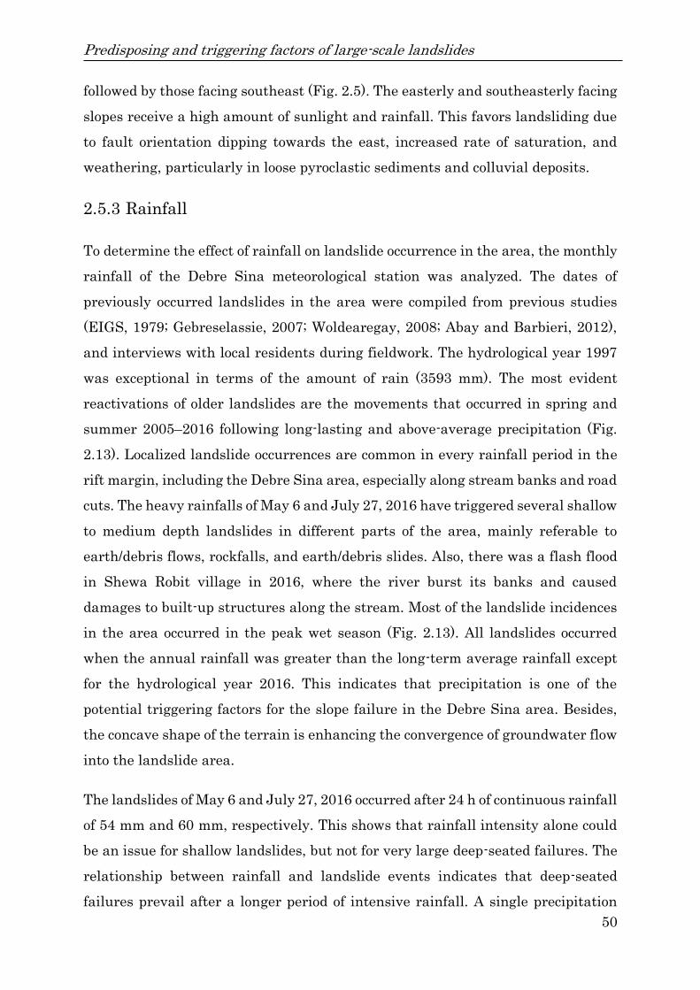
Predisposing and triggering factors of large-scale landslides
50
followed by those facing southeast (Fig. 2.5). The easterly and southeasterly facing
slopes receive a high amount of sunlight and rainfall. This favors landsliding due
to fault orientation dipping towards the east, increased rate of saturation, and
weathering, particularly in loose pyroclastic sediments and colluvial deposits.
2.5.3 Rainfall
To determine the effect of rainfall on landslide occurrence in the area, the monthly
rainfall of the Debre Sina meteorological station was analyzed. The dates of
previously occurred landslides in the area were compiled from previous studies
(EIGS, 1979; Gebreselassie, 2007; Woldearegay, 2008; Abay and Barbieri, 2012),
and interviews with local residents during fieldwork. The hydrological year 1997
was exceptional in terms of the amount of rain (3593 mm). The most evident
reactivations of older landslides are the movements that occurred in spring and
summer 2005–2016 following long-lasting and above-average precipitation (Fig.
2.13). Localized landslide occurrences are common in every rainfall period in the
rift margin, including the Debre Sina area, especially along stream banks and road
cuts. The heavy rainfalls of May 6 and July 27, 2016 have triggered several shallow
to medium depth landslides in different parts of the area, mainly referable to
earth/debris flows, rockfalls, and earth/debris slides. Also, there was a flash flood
in Shewa Robit village in 2016, where the river burst its banks and caused
damages to built-up structures along the stream. Most of the landslide incidences
in the area occurred in the peak wet season (Fig. 2.13). All landslides occurred
when the annual rainfall was greater than the long-term average rainfall except
for the hydrological year 2016. This indicates that precipitation is one of the
potential triggering factors for the slope failure in the Debre Sina area. Besides,
the concave shape of the terrain is enhancing the convergence of groundwater flow
into the landslide area.
The landslides of May 6 and July 27, 2016 occurred after 24 h of continuous rainfall
of 54 mm and 60 mm, respectively. This shows that rainfall intensity alone could
be an issue for shallow landslides, but not for very large deep-seated failures. The
relationship between rainfall and landslide events indicates that deep-seated
failures prevail after a longer period of intensive rainfall. A single precipitation

Predisposing and triggering factors of large-scale landslides
51
event is unlikely to trigger a deep-seated slope failure of large extent. Most of the
landslides shown in Fig. 2.13 do not have known month or date of occurrences
except the landslides in 2016. The inlet graph of the mean monthly precipitation
in Fig. 2.13 shows periods of intensive rainfall in July, August and November
(1997). The mean annual precipitation for the whole period is 1812 mm and
marked by a horizontal black broken line, as shown in Fig. 2.13.
Figure 2.13: Rainfall data from the Debre Sina station from 1974 to 2016 compared
with landslide events.
2.5.4 Earthquakes
The central highlands of Ethiopia are in close proximity to the most seismically
active regions of the country, such as the Afar Triangle and the MER, where well-
documented damaging earthquakes are common (Samuel et al., 2012). The
northwestern plateau and southeastern plateau are split by the active East African
Rift Valley, which has a history of generating large earthquakes (Zygmunt et al.,
2014). More than 90% of the seismic and volcanic activities are connected with the
rifts, but the seismic hazards to life and property and the greatest damaging effects

Predisposing and triggering factors of large-scale landslides
52
are found on the plateaus where the majority of the population resides. The Debre
Sina area is known for its seismic activities recorded in chronicles as well as in
measured records. The earthquake events that occurred between April 1841 and
December 1842 (Gouin, 1979) along the plateau’s escarpment triggered landslides
and rockfalls that destroyed the town of Ankober, which is located nearby the study
area (Fig. 2.14). The causes of such slope failures were aggravated by heavy rains
that had saturated the thin layer of clayish soil, precariously exposed along very
steep slopes (Gouin, 1979). During February 1974, tremors were reported in the
Debre Birhan – Debre Sina region; some of these tremors were also felt in Addis
Ababa (Alemayehu et al., 2012). Such tremors were caused by a sequence of
earthquakes with magnitudes less than 4.5 originating from the region to the north
and northwest of Debre Sina. This portrays that the effects of continuous shaking,
even if light, on slopes of marginal stability, are cumulative.
According to Ayele et al. (2009), an earthquake of magnitude 5.0 MI ruptured in
an area 25 km northwest of the Ankober town at 17:56:07 GMT on 19 September
2009. The tremor was recorded in Addis Ababa, about 160 km from the epicenter.
Furthermore, the area has been reported to have experienced a 6.0 magnitude
earthquake in 1983. This is the maximum recorded from the area where the
tectonic stress is mostly released by smaller magnitude shocks (Ayele, 2009).
During the fieldwork, interviewed local people and district administrators
regarding the reactivated landslide in 2016 said that there were earthquakes
shaking on 29 October 2015, 24 January 2016 and 1 May 2016, in the Debre Sina
area and surroundings. This is in good agreement with suggestions by Kropáček
et al. (2015) that the sliding events are driven by a combination of geologic and
tectonic predispositions together with external factors such as long-term water
saturation and seismic events. Figure 2.14 shows that a concentration of epicenters
follows the MER structures. However, the epicenter distribution is more
concentrated along the northeastern and western escarpment margin. Faults of
the rift margin suffer from occasional earthquake tremors leading to the activation
of unstable ground. Furthermore, there are several earthquake tremors recorded
in the period 2005, 2006, 2016, and 2017 in the region. Out of these, the seismic
tremor known to have been felt in the area close to the time of the deep-seated

Predisposing and triggering factors of large-scale landslides
53
landslide that took place on 13 September 2005 in the Debre Sina area
(Woldearegay, 2008) is that of the major seismo-tectonic event in north-central
Afar, in September 2005 (Yirgu et al., 2006). Although the earthquake around the
time of the main deep-seated landslide occurred afterward, foreshocks of lower
magnitude could have brought about a certain degree of instability in the already
susceptible terrain.
Figure 2.14: Recorded earthquakes in the East African region from 1842 to 2011
(source: EAGLE data).
As reported by Ayele (2009) and supported by subsequent researchers such as
Yirgu et al. (2006), and Abay and Barbieri (2012), the tectonic activity and
earthquakes might also be related to the activation of landslides in the form of

Predisposing and triggering factors of large-scale landslides
54
deep-seated gravitational creep. Particularly in the Debre Sina area, the role of
tectonic activity 2016 inducing landslides has been significant. The historical
earthquakes distribution can indicate that the seismic hazard in the central-
western highlands of Ethiopia is even higher. As there are intensive urban and
infrastructural developments taking place along hills and rugged mountains in the
study area and surroundings, very serious attention is required to consider the
seismic hazard in the area during planning, design, and construction phases.
2.6 Conclusions
The study area is located along the rift margin escarpment, a zone of notably high
potential for landslides. It is flanked by the lower and upper normal faults and the
Tarmaber–Mezezo mountain chain. This article presents six typical examples of
recent slope movements in the area. The studied landslide areas have been
evaluated in terms of their historical development, current status (based on the
field survey results), and geological and topographical conditions. Deeper
landslides are found in Yizaba Wein, Shotel Amba, Nib Amba, Nech Amba, and
Wanza Beret areas, whereas shallower depth landslides are found in the Shola
Meda area.
The area is covered by volcanic rocks and superficial deposits ranging in age from
Tertiary to the recent. The landsliding events were driven by a combination of
geologic and tectonic predispositions, together with external factors such as long-
term water saturation and/or seismic events. The rocks exhibit a variety of planar
discontinuities that originated during the volcanic formation and subsequent
tectonic disturbances. The presence of highly fractured porphyritic-agglomeratic
basalt, highly shattered ignimbrite and volcanic ash, which are prone to water
absorption and susceptible to slaking, was identified as one of the reasons for a
high concentration of landslides and main triggering factors of reactivation in the
observed cases. Therefore, it is evident that the inherent variation in the physical
property of the lithologic sequence and their structures influence the slope
stability.

Predisposing and triggering factors of large-scale landslides
55
Overall assessment of the morphometric analysis revealed that the slopes ranging
from 10° to 40°, with an elevation of 1800–2500 m and aspect to east and southeast,
are highly prone to sliding. The study area is densely traversed by faults and
lineaments with a variable pattern that denotes the formation of the variable
hydraulic system affecting mechanisms of surface and groundwater paths and thus
degrades rock mass strength but also increases the weight of the slope mass, i.e.,
increasing pull of gravity. The landslide displacement is orthogonal to NNE–SSW,
and N–S striking normal fault systems affected by NW and NE striking trans-
tensional components.
In general, the deep-seated translational and rotational landslides of the area are
controlled by different predisposing factors such as (i) geological-structural setting,
(ii) complex morphology of the slope, (iii) presence of closely spaced normal fault
segments with steep slope angles, and (iv) deepening of the Dem Aytemashy,
Majete and Shenkorge streams (active erosion and gullying). This study shows the
importance of recognizing both the predisposing factors and failure mechanisms
along rift margins and highland terrains linked to deep-seated potential landslides
and their disastrous consequences.
Acknowledgments
We express our deep gratitude to the anonymous esteemed reviewers and the
editors of the Bulletine of Engineering Geology and the Environment Journal for
their constructive comments and suggestions.
Funding information
The first author would like to thank the German Academic Exchange Service
(DAAD) for the scholarship grant to pursue the PhD study. This work was
supported by the Ruhr University Research School PLUS, funded by Germany's
Excellence Initiative (DFG GSC 98/3).
Tectonic conditioning revealed by seismic refraction
56
Chapter 3
3 Tectonic conditioning revealed by seismic
refraction facilitates deep-seated landslides in
the western escarpment of the Main Ethiopian
Rift
This chapter is based on Tesfay Kiros Mebrahtu, Michael Alber, Stefan Wohnlich
(2020b). Tectonic conditioning revealed by seismic refraction facilitates deep-
seated landslides in the western escarpment of the Main Ethiopian Rift.
Geomorphology 370, 107382. DOI: 10.1016/j.geomorph.2020.107382.
Abstract
Landslide is a geo-hazard phenomenon that has been taking lives and causing
severe property damages all over the world mostly in mountainous areas. The
Main Ethiopian Rift has a unique tectonic setting with complex geological and
geomorphological features, coupled with continuously deteriorating environmental
conditions, which made its escarpments vulnerable for landslides. The study area
is located near the Debre Sina town, within the Yizaba Wein locality, which has
been severely affected by frequent landslide problems. This work was carried out
using a multidisciplinary approach based on geological, geomorphological,
kinematic analysis and geophysical survey. Seismic refraction investigations were
carried out along the Yizaba Wein landslide main scarp to determine the depth to
the bedrock and to the failure plane, to assess the stability of the slope, to locate
possible structural features and to identify the extent of recent landslide activity,
and to study the subsurface situation. The seismic measurements were made along
three nearly orthogonal survey lines in the recently affected area. A high-
resolution 2D P-wave survey was conducted using a 24-channel seismic unit. The
seismic refraction results revealed four layers of geomaterials with distinct
physical characteristics that contained a subsurface landslide anomaly within the
layers. The layers were interpreted according to the major lithological units, from

Tectonic conditioning revealed by seismic refraction
57
top to bottom: (i) clay, loosely cemented colluvial sediments and highly weathered
agglomeratic basalt; (ii) highly to moderately fractured porphyritic basalt,
ignimbrite-volcanic ash and rhyolite/trachyte; (iii) moderately to slightly fractured
ignimbrite, rhyolite/trachyte and basalt and (iv) very strong, massive, fresh
rock/bedrock. Faults and weak zones have also been identified in the bedrock based
on the abundance of fractures and subsidiary faults resulting from damage of rocks
and change of lithology due to variable fault rock formation strongly influencing
the wavefield distribution which usually causes a local decrease of the velocity
value. The main findings show that the landslide in the Yizaba Wein locality was
caused by its complex geological-structural setting and downslope movement of the
underlying pyroclastic sediment facilitated by heavy rainfall. Considering the
similar geological and tectonic settings, similar mechanisms can be assumed for
other landslides along the rift margins and associated highlands of Ethiopia.

Tectonic conditioning revealed by seismic refraction
58
3.1 Introduction
Mass movements are among the common geohazards that cause major economic,
social and environmental problems in the world. A gravity driven down-slope
movement of soil or rock masses without requiring a fluid as a primary
transporting agent, is generally known as a landslide (Brunsden, 1999). The
unique tectonic setting and accompanying active rifting processes have exposed
Ethiopia for seismic and volcanic risks. Besides, its complex geological and
geomorphological features, coupled with the continuously deteriorating
environmental conditions, have made most parts of the country vulnerable for
landslides. Previous and recent tectonic activity are possibly directly or indirectly
influencing the occurrence of landslides by various factors. Landslides are one of
the most destructive natural hazards in the highlands and the rift margins of
Ethiopia (Ayalew, 1999; Temesgen et al., 2001; Ayenew and Barbieri, 2005).
Fatalities, destroyed infrastructure and agricultural lands as well as distortion of
the natural environment have been the consequences of several landslides (Ayalew
and Yamagishi, 2004; Woldearegay et al., 2005). Landslides are abundant and
frequent in central highlands and rift escarpments of Ethiopia, but their failure
mechanisms are not well understood yet. A single major deep-seated landslide that
took place on 13 September 2005 in the Debre Sina area demolished 1250 dwelling
houses and more than 3000 people were displaced. Moreover, one elementary
school, four churches, and four mills were destroyed (Woldearegay, 2008). The
damage caused by the landslide in the Debre Sina area and its surroundings is
immense in terms of human life, engineering structures, agricultural land, natural
environment, etc.
The magnitude of landslide occurrences and its resulting damage to infrastructure,
property, agricultural land and environment have been increasing from time to
time and there is still an active landslide hazard especially along the Yizaba Wein
locality. To protect human live and to reduce the financial loss due to landslide
incidences by appropriate mitigation measures, the driving factors of the
landslides need to be understood. A clear understanding of the geological setting,
as well as proper evaluation of the geophysical and geohydrological characteristics

Tectonic conditioning revealed by seismic refraction
59
of soil and rock masses, is the key for a slope stability assessment. Geophysical
techniques can be extremely helpful investigating landslides and have been
successfully applied to detect failure surfaces and the associated hydrogeological
regimes (Jongmans and Garambois, 2007). In landslide studies, geophysical
methods are used to determine the approximate thickness of the landslide debris
using different techniques, such as electrical resistivity tomography and seismic
refraction that are based on the determination of electrical resistivity/conductivity
and velocity of elastic waves that provide insight about characteristics of the
underlying earth materials (Pellegrini and Surian, 1996). As stated by Prokeˇsov´a
et al. (2014), geophysical investigation methods can help to locate historic and
potential landslide areas, but also in monitoring landslides during slip. Lateral
extend as well as depth to the failure surface can be determined through
geophysical investigations (Cummings and Clark, 1998; Bruno and Marillier,
2000; Mauritsch et al., 2000). Further parameters, such as groundwater levels or
moisture content, which are directly or indirectly related to slope failure, can be
derived from geophysical measurements (McCann and Foster, 1990; Hack, 2000;
Jongmans and Garambois, 2007; Heinze et al., 2019). Combined with an in-depth
understanding of the failure mechanisms and triggering factors, a characterization
of the landslide can be achieved. Reliable information on the current state, extent,
structure, sliding plane location, groundwater table are required for hazard
assessment (Bell et al., 2006). Seismic refraction has been used to identify
lithological layers, delineating failure surfaces and determining physical
properties of the landslide material (e.g., Bogoslovsky and Ogilvy, 1977; Bichler et
al., 2004; Glade et al., 2005; Otto and Sass, 2006; Göktürkler et al., 2008). Seismic
refraction is widely used in investigating the mechanical and geological conditions
which determine the nature of sliding movements.
Combined engineering geological and geophysical investigations for landslides
were conducted using seismic refraction, vertical electrical sounding (VES),
electrical resistivity profiling and magnetics in some parts of Ethiopia (Shimeles
and Getnet, 2016), but not in study area of this work. The study area was visited
by some researchers but there were no particular works on the deep-seated
landslide using geophysical methods. To deal with this problem seismic refraction

Tectonic conditioning revealed by seismic refraction
60
method was applied along with geological and geomorphological mapping and
assessment of landslide prone areas in the study area. The main goal of this work
is to identify geological and geomorphological features of the deep-seated landslide
of the Yizaba Wein locality in order to understand the predisposing factors that
control the development of the landslide, to examine the internal structure of
landslides and to assess the stability of the slope. We analysed a landslide that
occurred at the Yizaba Wein locality in 2005 to identify depth to failure plane,
possible slip surface and the mechanism of slope failures, existing situation of
faults and their continuity under the landslide, and to determine the internal
composition of the sliding masses for the characterization of similar landslides
using seismic refraction. While seismicity was recorded and reported around the
occurrence of the landslide in 2005, the focus point of this work is on the pre-
existing lithology and its relationship to the tectonic setup of the region rather
than on a possible seismic trigger.
3.2 The study area
Ethiopia is composed of four major physiographic regions, with the Main Ethiopian
Rift (MER) separating the northwestern and the southeastern plateau. In the
northeast, normal faults sloping towards the northwestern and noutheastern
plateau bound the Afar depression (Fig. 3.1). The study area is located in the
border zone of the Ethiopian highlands and the MER about 190 km to the north of
Addis Ababa (Fig. 3.1). The area is characterized by high elevation and topographic
variations, with elevation ranging from 1130 to 3696 m above sea level (a.s.l). The
area is transected by deeply dissected valleys and channels, canyons, rugged relief,
N–S trending outstanding ridge chains with steep cliff escarpments. The study
area contains several stream networks that originate in the highlands and proceed
further outwards through deep gorges and rift valleys. The average annual
temperature and rainfall is 15 °C and 1812 mm, respectively. The drainage pattern
is well defined with parallel to sub-parallel, dendritic, rectangular and trellis
patterns developed along faults and master joints in hard rocks. The most
spectacular landslide phenomena were observed at the Yizaba Wein locality, which
is to the north of Debre Sina town (Fig. 3.1).
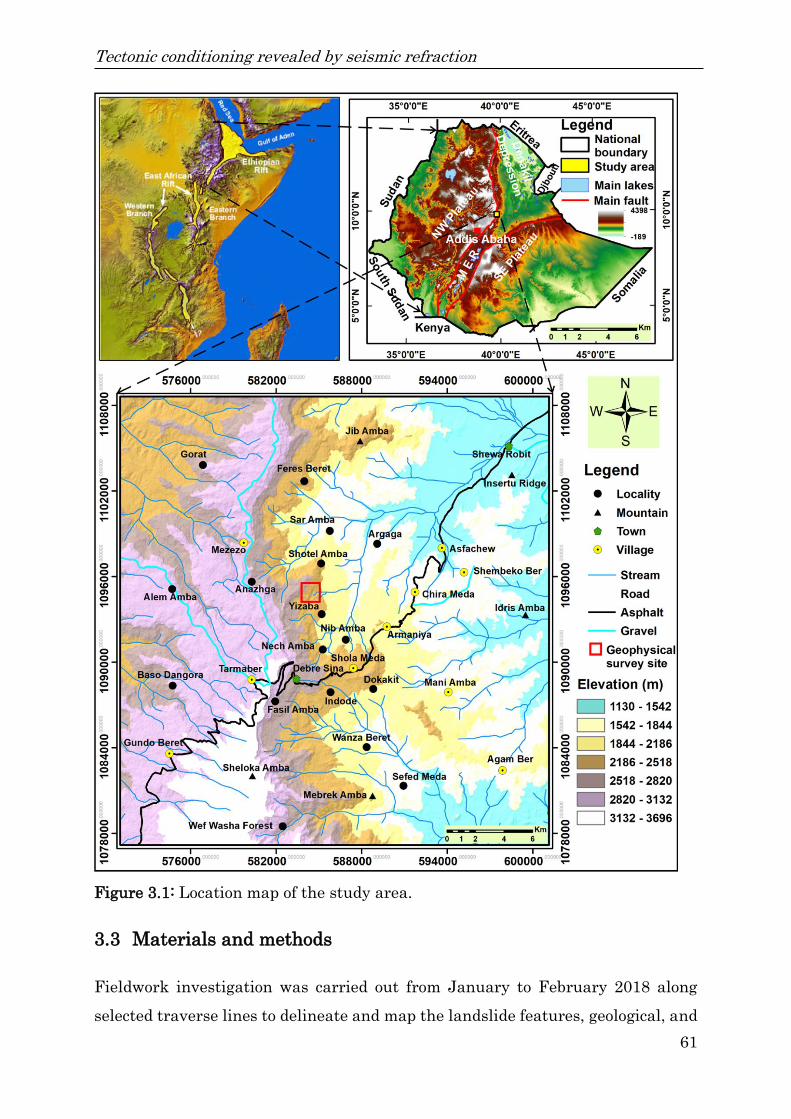
Tectonic conditioning revealed by seismic refraction
61
Figure 3.1: Location map of the study area.
3.3 Materials and methods
Fieldwork investigation was carried out from January to February 2018 along
selected traverse lines to delineate and map the landslide features, geological, and

Tectonic conditioning revealed by seismic refraction
62
topographical settings of the area. Moreover, the delineation and identification of
past landslides was defined by Google Earth imagery. Lineaments were extracted
from Landsat Enhanced Thematic Mapper Plus (ETM+) images and fieldwork.
Structural measurements of faults and joints were carried out to reveal the
structural predisposition of slope to deep sliding. In particular, stereographic
projection kinematics analysis method was performed in the main landslide area
to analyze the potential failure modes and the corresponding probabilities. The
strike and dip of the fault planes were reported in stereographic diagrams. A
geological cross-section was constructed along the seismic refraction profile in
order to link surface and sub-surface geological data.
Seismic methods are the most commonly conducted geophysical surveys for
engineering investigations. The seismic refraction uses seismic energy, which
returns to the surface after travelling through the ground along refracted ray paths
(Kearey et al., 2002). The first arrival of seismic energy at a detector offset from a
seismic source always represents either a direct ray or a refracted ray. Due to this
fact, refraction surveys can be carried out with the focus only on the first arrival (or
onset) of seismic energy, and time-distance plots of these first arrivals are interpreted
to derive information on the depth of refractive interfaces. The seismic refraction
survey was conducted on a hummocky, sloping surface of a landslide along three
nearly orthogonal survey lines within the recently affected area. For this study
three profiles were carried out with a horizontal length of 1 km. The profiles were
orientated perpendicular to the deep-seated landslide main scarp. The first and
second profile (hereafter L1–L2) extend in the NW to SE direction having a total
length of 600 m, while the third profile (hereafter L3) stretches from SW to NE with
a horizontal length of 400 m (Figs. 3.9 and 3.10). The topographic surveying work
using a total station unit (TS) was intended to determine the direction and layout of
seismic lines, marking and labeling of seismic shot points and geophone locations
along the corresponding lines.
3.3.1 Instrumentation and field procedures
The seismic refraction study was carried out by using SmartSeis unit of Geometrics
seismograph of the United States of America (USA), which is a 24-channel

Tectonic conditioning revealed by seismic refraction
63
seismograph, microprocessor-based with the latest hardware and software and
interfaced with a plotter. This unit includes a state-of-the-art internal computer for
pre- and post-recording, filtering, and partial processing facilities. The signals
were generated using a 7 kg sledgehammer and a metal plate as a seismic source.
PE-3 geophones with a natural-frequency of 10 Hz were used to receive signals.
The seismic profiles were later processed using Rayfract TM v 3.34 (April 2016)
tomography software (http://rayfract.com), together with a classic refraction
processing software package. The survey was undertaken using in-line profiling
and reversed recording method. A spread length of 115 m with 5 m geophone
spacing was used. For a continuous subsurface mapping, successive spreads with
2 geophone overlap were used. In order to have a regression of arrival times from
the various subsurface formations, on each spread, a total of five shots were
employed where the topography allowed to do so. A total of seven shots per spread
were used with a shot point spacing of 25 m (Fig. 3.2). The shots are two offset
shots (direct and reverse), direct, central and reverse shots. The energy source used
was a 7 kg sledgehammer. Several hammer impacts were stacked for each shot
point. Mostly, the signal is stacked in the seismograph 5 to 15 times to increase
amplitude of the refracted signal and to cancel random noise, as a result first
breaks are enhanced and also signal to noise ratio is improved. The survey lines
were laid down and pegged at 5 m intervals with coordinates and elevation
recorded on each pegging point. Besides, in order to avoid noise created by different
unnecessary sources, the geophones were buried into a 20 cm deep hole. The
refraction field parameters and geometry of seismic shooting (field observations) are
summarized in Fig. 3.2 and Table 3.1.
Survey results are mainly affected by data quality, data processing, and
interpretation procedures. Data quality in the present survey area could be
influenced by ambient noise, geologic noise, surface irregularities (topographic
problems, and outcropping rock which presents problems in establishing contact
between geophones and the ground surface). The depth of investigation from the
present seismic refraction survey was attained with a maximum of 75 m.

Tectonic conditioning revealed by seismic refraction
64
Figure 3.2: The layout of the seismic refraction survey.
Table 3.1: Parameters of seismic refraction used during fieldwork.
Description Type/magnitude
Energy source Sledgehammer
Geophone distance 5 m
Length of spread 115 m
Shot position –22.5, 2.5, 27.5, 52.5, 77.5, 102.5, 127.5…
Recording Time 128 ms – 512 ms
Sampling 0.0625–0.125
Filtering Open
Amplification Auto trace (mostly)
3.3.2 Data acquisition, processing, and presentation
The field data was processed in a conventional manner, by manual work in which the
P-wave velocities determined from the first arrivals were used for the
interpretations. The first arrivals in the seismic signals are picked to determine the
transit time from shot position to the geophone. In the inversion process, a tomogram
of the P-wave velocity distribution in the subsurface is calculated based on the
determined transit times (Kearey et al., 2002). The frequency filtering options of the
instrument were utilized to eliminate unwanted signals or noise. The seismograms
were produced using the internal computer of SmartSeis exploration seismograph
with the following standard processing parameters:
Display mode: Average limited
Time scale: Normal
Print time scale: Compressed

Tectonic conditioning revealed by seismic refraction
65
Automatic Gain Control (AGC): Fixed Gain
Low cut filter: Open or 10 Hz
High cut filter: Open or 180 Hz
3.3.2.1 Conventional approach
From the first arrivals, time-distance (T–D) curves were plotted and verified for
reciprocity, parallelism, number of possible layers which could be mapped, and
presence of overlapping events for the same refractor over each spread.
Subsequently, velocity analysis was performed taking into account the survey layout
geometry, number of shots available, and number of overlapping events for each
spread. For the first and second layers the velocities have been determined using the
inverse slope of the lines of best fit of the inner time-distance plots. The noise has
been removed using the inherent filtering facility of the TERRALOC internal
computing system. The first arrival times were picked up using auto pick option of
the system for all records and few adjustments were made manually where it seemed
necessary. Various corrections were made on the recorded data (elevation, shot point,
and phase) prior to analysis, to remove influences caused by surface irregularities.
In some cases, due to the limited energy by the sledgehammer, the signal to noise
ratio was found to be small; in such cases, secondary arrivals were used to correct
the first arrivals. After plotting these corrected times against source-geophone
distance (time-distance curve) the reciprocity and parallelism between the different
refractors have been evaluated and the necessary processing was made (Figs. 3.3
and 3.4). An initial velocity-depth model was generated by sorting the travel times
and assuming several horizontal layers with constant internal velocity gradients
(Gebrande and Miller, 1985; Rohdewald, 2011).
From the travel time curves, the number of layers can be estimated as well as first
assumptions of their apparent velocities can be made. The inverse slope of the first
line segment gives the velocity of the first layer while the apparent velocity of the
second layer is determined from the inverse slope of the second line segment. The
first layer velocity (V1) was determined by averaging the inverse slope of the direct
(V1d) and reverse (V1r) recordings since those are direct waves, not refracted ones
(Eq. (3.1)).

Tectonic conditioning revealed by seismic refraction
66
V1 =(V1d+V1r)
2 (3.1)
The second layer velocity (V2) was estimated by taking the harmonious mean of
the apparent up-dip (V2d) and down-dip (V2r) velocities (Eq. (3.2)), as there has been
no sufficient overlap of travel times (Kearey et al., 2002).
V2 =2V2dV2r
(V2d+V2r) (3.2)
Depth equation at impact points for an arbitrary n number of velocity layers from
intercept time is given as follows (Eq. (3.3)) (Sjögren, 1980).
ℎ(𝑛 − 1) = 1 2⁄𝑇𝑛𝑉𝑛𝑉(𝑛−1)
√𝑉2𝑛−𝑉2(𝑛−1)−
𝑉𝑛𝑉(𝑛−1)
𝑉2𝑛−𝑉2(𝑛−1)∑ ℎ𝑣√(
1
𝑉2𝑣−
1
𝑉2𝑛)𝑣=𝑛−2
𝑣=1 (3.3)
where, Vn= velocity of the nth layer, Tn= nth intercept time and h= depth.
Depth analysis and velocity distribution in the bottom refractor are carried out by
using the T–0 method (Gurvich, 1972), and the mean-minus T and ABC-curve
methods (Sjögren, 1980; Robert, 1995). The advantage of Mean-Minus-T method
over the others is that it verifies the lateral velocity variation as accurate as
possible (Sjögren, 1984). It also unmasks the irregularity of the refractor
topography in depth determination. Velocities estimated by the above methods
were compared and calculated. This, in turn, has allowed to improve accuracies in
the determination of refractor velocities and therefore layering thicknesses.
3.3.2.2 Improved/latest approach
After the necessary partial data processing within the seismic unit, manual data
processing which includes correction of arrival times and analysis of preliminary
seismic models, a software-assisted data processing has also been carried out. This
was done using the Rayfract 32 software package. This package provides an image
of the subsurface based on seismic first break energy propagation modeling. In this
method, a starting model is calculated based on the travel times. Using the 2D
Wavepath Eikonal Traveltime (WET) inversion, the P-wave velocity distribution
was calculated based on the derived travel times (Schuster and Quintus-Bosz,
1993; Lecomte et al., 2000). In the course of the present work, the partially

Tectonic conditioning revealed by seismic refraction
67
processed, corrected and checked data have been used to produce WET
tomographic sections through smooth inversion and refined Delta-t-V inversion
(Figs. 3.15 and 3.16) methods which were in turn later refined by the WET
tomographic inversion method (Figs. 3.9 and 3.10). The refraction seismic time-
distance curves first break and their corresponding fits difference between
measured (instantaneous) and inverted (CMP layer) are shown in (Figs. 3.3 and
3.4). The P-wave velocities remaining root-mean-square (RMS) error between
modelled and measured data is less than 2%.
Figure 3.3: Time-distance curve along profile one and two (L1–L2) that black line
is the fit.
Figure 3.4: Time distance curve along profile three (L3) that black line is the fit.

Tectonic conditioning revealed by seismic refraction
68
3.4 Results
3.4.1 Geology and geomorphology of the study area
The geology of the area is mainly composed of (i) aphanitic basalt-porphyritic-
agglomeratic, (ii) ignimbrite-tuff-volcanic ash, (iii) porphyritic basalt-scoriaceous
agglomerate, (iv) Tarmaber basalt, (v) colluvial deposit and (vi) alluvial deposit
(Fig. 3.5). The aphanitic basalt-porphyritic-agglomerate units crop out in the gully
areas and series of steep cliffs and benches in deeply dissected valleys (Fig. 3.5).
The ignimbrite-tuff-volcanic ash unit crop out in lower part of the slope, underlain
by aphanitic basalt-porphyritic-agglomerate and overlain by porphyritic basalt-
scoriaceous. The ignimbrite-tuff-volcanic ash beds form small cliffs, which are
highly altered and intensely weathered, vertically jointed and highly shattered by
faulting (Mebrahtu et al., 2020a). The porphyritic basalt-scoriaceous agglomerate
unit consists of dominantly porphyritic basalt and scoriaceous agglomerate with
subordinate aphanitic basalt and vesicular basalt. These units show abundant
spheroidal weathering and breaks easily to very small size material. The Tarmaber
basalt unit is mainly exposed in the western part of the study area in the high
rising mountain chains. This rock formation forms vertical cliffs and ridges
trending in N–S direction.
The colluvial deposits cover the slopes with lower inclination, presumably
transported down-slope by gravity. They contain rock fragments and soil derived
from fragmented and weathered bedrock. In particular, the outcropping rocks in
the Yizaba area are deeply weathered and covered by colluvial materials, locally
including pyroclastic materials. The alluvial deposits are restricted along the
major riverbeds, riverbanks and their tributaries representing riverbeds and
terraces (Mebrahtu et al., 2020a). They are derived from the weathering,
transportation, and reworking of different rocks from the steep cliffs and
escarpment. The study area has been affected by N–S, E–W, NNE–SSW, NE–SW,
NW–SE, NNW–SSE, and WSW–ENE major trends of faulting (Fig. 3.5). These
faults experienced weathering down to greater depths causing thick soil layers and

Tectonic conditioning revealed by seismic refraction
69
show a high groundwater potential, which might trigger landslides through high
pore pressures and reduced friction.
The geomorphological survey was carried out to identify and map the main surface
features associated with gravitational processes of the topographical surface. The
geomorphological survey shows that various landforms have been identified in the
area, including structural, fluvial and slope forms. The morphological setting of
the area is very complex and strongly influenced by rock weathering, erosion, and
tectonics. The geomorphology of the study area is closely related to the
development of the MER system and recent river erosion. Deep fluvial dissection
has imprinted the geomorphological landscapes of the area and its surroundings.
The deep-seated landslides also modify the slope morphology of the study area. The
Yizaba–Shotel Amba slope shows clear morphological evidence of a deep-seated
landslide (e.g., breaks on the slope, depressions, terraced surfaces, and complex
convex–concave forms) (Fig. 3.6).
The slope morphology is also clearly controlled by the superimposition of mass
movements on a large-scale. Tension cracks of different size and opening are
recognized in the main body of the Yizaba landslide (Fig. 3.5). The major ground
deformation observed in the area during the fieldwork is represented by tensile
fissures, forming back scars and back tilting blocks (Fig. 3.6). Based on the
landslide classification following Cruden and Varnes (1996), the shape of the
cracks indicates translational and rotational character of the movement in the
upper part of the affected slope. Shear cracks developed systematically in sliding
colluvial deposits and pyroclastic sediments (Fig. 3.5). The Yizaba Wein landslide
can be divided into two main parts, which are indicated by the old and new scarps.
The upper part of the slope was formerly a head scarp, and the lower portion a
convex-concave slope with a gentler top surface. The new scarp runs parallel to the
topographic break of a pre-existing landslide (Figs. 3.5 and 3.6). Landslides and
deepening stream channels play an important role in the landscape development
of the study area. Below the new scarp, the bedrock is exposed and consists of
highly weathered porphyritic basalt and tuff-volcanic ash. The frontal part of the
moving mass is widely affected by multiple, retrogressive and successive debris

Tectonic conditioning revealed by seismic refraction
70
slides and earth flows induced by the lateral erosion of the stream, particularly
active in the rainy season. The instability in the Yizaba Wein locality is in the
recurrent stage with instabilities occurring on areas showing to have undergone
previous slides.
Figure 3.5: Geological and geomorphological map of the study area.

Tectonic conditioning revealed by seismic refraction
71
The upper portion of the scarp slopes varies approximately between 30° and 60° to
the east and is clear of landslide debris. The lower portion of the scarp is mantled
by a colluvial wedge.
Figure 3.6: Panoramic view of the main Yizaba Wein landslide and surroundings
from the east located in north direction of Debre Sina area.
The morphology of the area is also conditioned by numerous mass movements,
including rotational slides, translational slides, rockfalls and toppling, rock slides,
debris slides, and earth flows (Figs. 3.5 and 3.6). The spatial distribution of the
landslide types essentially depends on the type of materials involved (lithology and
structure of the bedrock, nature of overburden materials) and the slope angle. The
instability of the entire Yizaba slope system was influenced by the pressure of
active landslides from the Yizaba slope. The area is typically characterized by an
irregular hummocky topography, with deeply incised valleys and sharp steep
slopes, gentle slopes, cliffs, and escarpments crossed by the Dem Aytemashy river
and its tributaries. They are commonly deeply weathered and covered by colluvial
materials. These materials are shifted downslope by debris flow and earth flow
movements and tend to fill up small valleys and inter-hill depression (Fig. 3.5).
Moreover, large-scale slides affect the colluvial materials and pyroclastic

Tectonic conditioning revealed by seismic refraction
72
sediments, covering the hummocky topography. The colluvial deposit is diffusely
affected by shallow-deep multiple retrogressive and successive rotational slides.
The colluvial deposits are considered likely to be derived from ancient landslides,
probably associated with movement along layers of weathered tuff/volcanic ash
within the volcanic sequence.
The NE–SW trending Yizaba–Shotel Amba fault escarpment (Figs. 3.5 and 3.6) is
affected by a huge retrogressive rotational and translational rock slides and
toppling. Recent rock slides and toppling deposits derived from the overlying
porphyritic basalt cliffs occupy the margins of the valley and there are debris slides
that extend down to the river on the western side (Fig. 3.6). The intervening cliffs
are often formed in open-jointed rocks, posing slope stability problems. The gullies
that drain these valleys convey large volumes of sediment during the wet season,
mostly in the form of debris slides and flows. Springs are mainly observed in the
main scarp of the landslide and below the scarps (Fig. 3.5). The Dem Aytemashy
river, which plays an important role for the Yizaba area deep-seated landslide
development by slope undercutting, is structurally controlled by a NE–SW fault
segment that has guided the river incision and produced gully with toe erosion and
slope undercutting (Fig. 3.5). They often correspond to sets of fractures existing as
result of tectonic deformations. During the rainy season, runoff from the western
mountains forms a number of gullies. In addition to this, valley widening occurred
as a result of river erosion and landslides. Extreme undercutting of the base of the
sliding slope by the rivers contributed to the destabilization of the slope and thus
facilitated the landslide in the study area.
3.4.2 Profile one and two (L1–L2)
The profile L1 was surveyed above the main scarp (head scarp zone) towards NW
direction, whereas the profile L2 is below the main scarp (main slide block zone)
towards SE direction (Fig. 3.7a). The ground surface along the profile L1–L2 is
relatively flat in the southeastern part of the line and gently slopes in the
northwestern direction. The inverted P-wave velocity tomograms cover a broad
range of velocities ranging from 400 m/s to 5400 m/s (Figs. 3.9 and 3.15). The smallest
velocities (Vp 500 m/s) are found in the lowermost flat slope. In the P-wave

Tectonic conditioning revealed by seismic refraction
73
tomogram (Figs. 3.8 and 3.9) four different lithologies can be distinct based on
lithological outcrops in the area. The lower P-wave range ( 1000 m/s) in profile
L1–L2, reflects the response from unconsolidated sediments exposed mostly on the
lower relatively flat terrain, gently sloping elevated parts and at the top part
towards NW. Line L2 is roughly 200 m away from the main scarp covering the
damaged zones of the main body towards the SE. The top material is similar to the
sliding mass of the steeper slope, so that the lithological layers identified in profile
L1 are continued, though vertically displaced by a potential fault. Moreover, the P-
wave range of the lower layer (1000–1500 m/s) indicates a mixture of the upper
material with agglomeratic basalt. The top unit disappears between stations 400–
435 and around station 560 (Fig. 3.9), which is moved towards the lowermost gentle
slope. The unit has a thickness in the range of 7–15 m, with further increasing
thickness towards the SE of station 500. This unit is underlain by relatively
cemented highly weathered/decomposed materials and agglomerates represented
by the P-wave velocity range (1000–1500 m/s). The above two sequences of
sediments comprising the top velocity layer, with P-wave velocities below 1500 m/s,
have thickness up to 30 m.
Generally, this layer thickness ranges between 10 and 30 m excluding the above
two zones where it vanishes. Its maximum thickness is associated with the
downthrown part of the line between stations 300 and 320. The intermediate unit
with the P-wave range (1500–2000 m/s) is mapped along the entire length of line
L1. This unit is exposed to the surface around station 400, where it attains a
maximum thickness of about 30 m coinciding with a fault (Figs. 3.7a–b and 3.9).
This unit appears relatively compact with the P-wave range (2000–2500 m/s)
towards its bottom. These units, having the same range of velocities, appear to
correspond to different lithologic units as observed at the outcrops. This could be
an indication of water saturation in the soil due to seepage and drainage through
fissures and fractures. Consequently, groundwater in the elevated parts of the area
is expected to be manifested in the form of seepages (springs), which could
contribute pressure in the direction of flow which is towards the lower elevated
area, as indicated by the arrows in Fig. 3.9.

Tectonic conditioning revealed by seismic refraction
74
Figure 3.7: Typical landslides in the study area: (a) translational slides in
porphyritic-agglomeratic basalt and seismic refraction line L1–L2 location, (b)
rotational slides on colluvial deposit and volcanic ash/tuff, (c) rock slides in
porphyritic basalt and seismic refraction line L3 location, (d) earth slide in clay soil
and colluvial deposit.
Figure 3.8: Geological cross section along selected line A–B.

Tectonic conditioning revealed by seismic refraction
75
In the lower elevated sides, to the southeast of station 350, the groundwater level
could be between 2250 and 2270 m a.s.l. The intermediate unit with P-wave
velocities between 1500 and 2400 m/s may be partially saturated. The underlying
relatively higher velocities with 2500 m/s are interpreted as comprising the upper
part of the bedrock (Fig. 3.9).
Figure 3.9: Seismic refraction tomography 2D P-wave velocity cross-section along
profile L1–L2.
The intermediate units with a P-wave range between 2500 and 3500 m/s may be
related with moderately to slightly fractured volcanic rocks. The thickness of this
unit is in the range of 7–20 m. The P-wave velocities of this unit increase depth-
wise suggesting an increase in the degree of compaction and quality of the bedrock.
Accordingly, the P-wave velocities above 3500 m/s reflect very fine, stronger and
very sound rocks, and probably aphanitic basalt. The depth to the sound bedrock
is found within 45–75 m. The maximum depth is associated with the fault zone
around station 500 m. Moreover, geological structures are inferred around stations

Tectonic conditioning revealed by seismic refraction
76
330, 400 and 520 associated with potential future landslides and presently instable
areas (Fig. 3.9). The P-wave velocity interpretation of the three profiles is based on
lithological outcrops, surface observations and geological setup.
3.4.3 Profile 3 (L3)
The inverted P-wave velocity ranges from 400 m/s to 4400 m/s (Figs. 3.10 and 3.16).
The smallest velocities in the P-wave tomogram (Vp 500 m/s) are found in the
lowermost gentle slope. Again, the tomogram allows the identification of the same
four lithological units. Thus, the uppermost units are represented by P-wave
velocities below 1000 m/s attributed to clayey soil, highly weathered/decomposed
materials and colluvium with thicknesses generally increasing towards northeast
from about 3 m to a maximum of 20 m around station 380. Towards the NE, the P-
wave velocity is significantly reduced, coinciding with a drop in ground elevation.
The bedrock is mostly covered by colluvium deriving from the uppermost gentle
slope. At the bedrock, the P-wave velocity is strongly discontinuous, increasing
from Vp 500 m/s to Vp 1000 m/s. The underlying unit with a P-wave velocity
between 1000 and 1500 m/s has a varying thicknesses between 5 m and 25 m.
Maximum variations are noted between stations 200 and 250 where the unit
narrowly extends depth-wise towards the lower elevated side (Figs. 3.10 and 3.7c).
This unit is associated with highly fractured and weathered volcanic rocks and
colluvium.
The third lithological unit has a P-wave range between 1500 and 2500 m/s. It
reflects wider variations in the central part of the area probably due to
compositional variations. Its maximum thickness is above 45 m and situated
around station 240 where this unit extends depth-wise towards the lower elevated
zone associated with the inferred fault (Fig. 3.16). The upper part of the bedrock is
marked with P-wave velocities of 2500 m/s extending along the entire length of the
profile. The degree of compactness and quality of the rocks increases with depth as
reflected from the increasing P-wave velocities. However, a fault is found around
station 230 and the bedrock P-wave velocity is relatively lower probably attributed
to brecciating and fracturing. The depth to the relatively sound bedrock (Vp 3500
m/s) undulates between 50 m and 72 m. The maximum depth (72 m) is found

Tectonic conditioning revealed by seismic refraction
77
associated with the inferred fault in the central part of the line. In addition to the
major fault in the central area, a fracture zone and an inferred fault are also shown
around stations 125 and 370, respectively (Figs. 3.10 and 3.16).
Figure 3.10: Seismic refraction tomography 2D P-wave velocity cross-section along
profile L3.
3.4.4 Kinematic analysis of slope failure
Kinematic analysis was performed to determine the failure modes of the rock slope
by interpreting the stereonet. The back-analysis of the stability of the landslide
area was prior to the landslide event in 2005. In this study, Rocscience Dips Version
7.0, a graphical and statistical analysis of orientation data software, was utilized to
analyze and visualize the orientation data. In a kinematic analysis various modes of
potential rock slope failures such as planar sliding, wedge sliding and flexural
toppling that occur due to the presence of discontinuities in unfavourable orientation
can be studied (Hoek and Bray, 1981; Goodman, 1989). The stability of the rock
slopes is highly influenced by the orientation of discontinuities like joints, faults,

Tectonic conditioning revealed by seismic refraction
78
bedding planes, etc. The three faults located along the main scarp, as shown in
Figs. 3.5 and 3.11 are plotted on the stereonet according to the fault orientation
details as given in Table 3.2 and friction angle of 30°. First, the mode of failure of
each sliding has been defined by providing the kinematic properties, such as planar
sliding, wedge sliding and flexural toppling. There are two types of failure modes in
the study area: planar sliding and wedge sliding (Figs. 3.12 and 3.13). The analyses
for planar and wedge failures were done on each plot using a basic friction angle
of 30° (Barton, 1976) and mean dip direction of 85°. The friction angle is used as a
first approximation to the stability analysis of the slopes along faults in hard rock.
Figure 3.11: The main Yizaba Wein landslide located in north direction of Debre
Sina town: fault 1–green (NNE–SSW), fault 2–blue (NNW–SSE) and fault 3–
purple (WSW–ENE).
The variables that contribute to the probability of failure are slope orientations,
friction angle and lateral limits. The input data for the kinematic analysis of
planar and wedge failures are summarized in Table 3.2. Especially discontinuities

Tectonic conditioning revealed by seismic refraction
79
have a strong impact on the strength of a material, as they reduce frictional and
cohesional strength and provide water pathways to deeper layers. As shown in Fig.
3.11, the slope is dominated by various parallel tensional fractures, which might
allow surface runoff to penetrate the subsurface. The interaction of these fault
systems produced complex displacement across and along the study area. The
density of the fractures in tilted basalt and ignimbrite-volcanic ash materials are
weak zones facilitating water infiltration into the volcanic ash levels. The green,
blue and purple broken lines as shown in Fig. 3.11 represent fault 1, fault 2 and
fault 3, respectively. According to the interpretation of the topographic profiles, the
maximum estimated thickness of the active main landslide body is approximately
150–200 m, whereas the maximum thickness of the old slope failure is up to 300–
400 m (Kropáček et al., 2015).
The stereonet presented in Fig. 3.12 is about planar sliding kinematic analysis
failure mode in pole vector mode. From Fig. 3.12, the region highlighted in red is
the critical zone for planar sliding where it is inside the daylight envelope and
outside the plane friction cone. Any pole failure within the daylight envelope will
not slide if frictionally unstable. On the other hand, any pole falling outside of the
represent planes with a dip steeper than the friction cone represents planes will
slide if kinematically possible. All poles that are plotted in the region in red are
representing a risk of planar sliding. The kinematic analysis result of planar
failure of the landslide event in 2005 with an average slope angle of 75° is as shown
in Fig. 3.12. For fault 3 which is circled in red, 1 out of 3 poles is in the critical
region. Therefore, the risk of the occurrence of planar sliding is about 33.33%. This
indicates that sliding along any single fault plane is likely to occur in the geological
plane having a dip direction of 90°.
Fig. 3.13 depicts the stereographic projection of the wedge sliding kinematic
analysis. In wedge sliding, a wedge is formed through intersection of two planes
and slides along those intersections. Wedge failure occurs when the line of
intersection dips steeper than the friction angle. The kinematic is mainly
controlled by orientation and geometry of the slope plane and the intersections as
well as the friction along the plane surface. The slope plane defines the day-

Tectonic conditioning revealed by seismic refraction
80
lighting condition (Fig. 3.13). Any intersection point which plots outside the pit
slope great circle satisfies the daylighting condition. The plane friction cone is the
angle measured from the equator of the stereonet. The critical zone for wedge
sliding is the red area in Fig. 3.13. If the intersection point falls in the red area in
Fig. 3.13, the intersection of two joint planes could cause a wedge sliding. On the
other hand, the secondary critical zone is highlighted in yellow in Fig. 3.13.
Figure 3.12: Stereonet of planar sliding kinematic analysis.
The kinematic analysis result of wedge failure of the landslide event in 2005 with
an average slope angle of 75° is as shown in Fig. 3.13. The risk of the occurrence of
wedge sliding is about 66.67%. The wedge formed by the intersection of fault 2 and
fault 3 is more critical than fault 1 and fault 3 as it lies within the primary critical
zone for wedge sliding. In both cases the wedge sliding takes place predominantly
along the plane formed by fault 3 as the dip vector of this plane is larger than the
friction angle and at the same time, the differences between dip direction of the
slope and fault plane 3 being less than the lateral limit of 30°.

Tectonic conditioning revealed by seismic refraction
81
Figure 3.13: Stereonet of wedge sliding kinematic analysis.
Table 3.2: Kinematic analysis of planar and wedge failures.
SID Dip direction Dip Trend Plung
Fault 1 105 85 285 5
Fault 2 65 80 240 10
Fault 3 85 60 270 30
Mean 85 75 265 15
Variance 400 175 525 175
According to Kropáček et al. (2015), the Yizaba Wein landslide of 2005 had an
estimated depth of 150–200 m and a volume of 1.7 km3, affecting an area of 6.5
km2. The rose diagram of the lineaments orientation data indicates four trends;
N–S, E–W, NE–SW and NW–SE (Fig. 3.14). Among these the N–S and E–W trends
are widespread in the area with the highest frequency. The discontinuities in the
area are generally open, smoothly undulating, lowly to highly persistent, and
intersecting each other (Mebrahtu et al., 2020a). The average spacing of the
discontinuity sets ranges from 0.23 to 0.54 m.

Tectonic conditioning revealed by seismic refraction
82
Figure 3.14: Rose diagram showing strike direction.
3.5 Discussion
Four soil and rock layers incorporating subsurface landslides were identified by
the seismic refraction method. The seismic refraction study revealed zones of
overburden material comprising, from top to bottom: clay, loosely cemented
colluvial sediments and highly weathered material (Vp 1000 m/s) of 7–15 m
thickness and highly weathered agglomeratic basalt (1000–1500 m/s) with
thicknesses up to 30 m. These units are highly susceptible to sliding when it gets
moist, because the volcanic ashes are prone to slaking and acts as lubricant
material (Fig. 3.9). The intermediate units comprise weathered and fractured
volcanic rocks (1500–2000 m/s) with a maximum thickness of about 30 m and
moderately fractured porphyritic basalt, ignimbrite-volcanic ash and
rhyolite/trachyte, relatively compact (2000–2500 m/s). The depth to the upper part
of the bedrock marked by the P-wave velocity of 2500 m/s is in the range of 40–50
m. The third unit probably comprises moderately to slightly fractured (2500–3500
m/s) ignimbrite, rhyolite, trachyte and/or basalt. The thickness of this unit is
between 7 m and 20 m in profile L1–L2 and 5–35 m in profile L3. The quality of the
bedrock increases with depth from slightly weathered/fractured rocks to fresh rocks

Tectonic conditioning revealed by seismic refraction
83
probably comprising aphanitic basalt (Vp 3500 m/s). Depth to very fresh sound
bedrock ranges between 45 m and 75 m (Figs. 3.15 and 3.16).
The 2D P-wave tomography section showed in Figs. 3.15 and 3.16 allows to draw
assumptions about the layers stratification. Each layer shows minor distortions in
its morphology but in general the lithology along profile L3 oriented in NE–SW is
similar to the ones seen in L1 and L2, oriented NW–SE. This agrees well with the
assumed continuity of the major lithological units. The result obtained from the
2D profile model is in good agreement with the results obtained from the geological
mapping. Further, the measured P-wave velocities of the different geological units
coincide with previous obtained wave velocities in the literature (Ellis and Singer,
2007; Schon, 2011). The morphology in combination with the tectonic assemblage
and the intense weathering processes strongly favors the mass movement. The
seismic refraction line shown in Fig. 3.15 emphasized a scarp in the bedrock which
is located along the prolongation of a NNE–SSW trending fault. The scarps and
linear depressions developed as a result of deep-seated gravitational slope
deformation that preceded the failure. The landslides occurred in the lower parts,
gravitationally deformed slopes leaving unstable slopes above. Field observations
confirmed that many types of landslides are densely distributed in the porphyritic
basalt, ignimbrite, volcanic ash, and colluvial deposit.
It is known, that seismic refraction is very suitable to reveal the sliding surface
due to the usually significant velocity contrast between sliding mass and bedrock
(Heincke et al., 2006; Donohue et al., 2012; Yamakawa et al., 2012). From a geo-
hazard point of view, the subsurface for profile L1–L2 is divided into three parts:
Zone 01 (area to the SE of station 300), relatively stable bedrock, with minor
undulation and no significant geological structure; zone 02 (area between stations
300 and 420), gently sloping ground surface with recently moved mass, and not yet
stable. The direction and slip surface of the landslide that has taken place in 2005
is situated above the position of the interpreted major fault (Fig. 3.9, arrow A). The
inferred fault around station 330 may also mark an old slide boundary. Zone 03
(the area between stations 420–520): sloppy terrain, embodied between two faults,
bedrock with 3500 m/s not seen or deep, favourable morphology, and unstable zone.

Tectonic conditioning revealed by seismic refraction
84
The velocity model essentially shows low-velocity slide material overlying a
concave, higher velocity layer (Fig. 3.15). The high-velocity material at the base of
the profile is interpreted to represent bedrock and dips southeastward towards the
river. Fig. 3.9 arrow B shows possible future slide slip direction which may coincide
with the inferred fault around station 520. The slip surface generally coincides
with the 2000 m/s isoline (marked by yellow broken line as shown in Figs. 3.15 and
3.16) due to the presence of highly fractured and saturated nature of the
underlying rocks.
Figure 3.15: Delta-t-V inversion along profile one and two (L1–L2).
The seismic refraction tomography shows distinct refractors which are interpreted
as the surface of the bedrock. Most likely, this surface corresponds to the main slip
surface of the landslide. The porphyritic-agglomeratic basalt, ignimbrite-volcanic
ash and colluvial deposit dipping downslope favor the development of rather deep-
seated rotational slides over discrete strata and have been significantly reactivated
in the last years. In the new scarp and its upper part, the input of debris from the
upper head scarp zone is a relevant process. This occurs by the progression of the
marginal portion of the sliding colluvial sediments and volcanic ash slab (Fig.

Tectonic conditioning revealed by seismic refraction
85
3.15). The upper layers of unconsolidated deposits and porphyritic-agglomeratic
basalt rocks experiences significant water transit towards the deeper layer of
ignimbrite-volcanic ash. However, the pyroclastic sediments are impeding the
vertical percolation of rainwater due to their low permeability and hence force the
rainwater to flow laterally. The volcanic ash beds also act as excellent slip surface,
especially when they are weathered. The increasing pore-water pressure and
seepage force in the colluvial deposit may favor slope instabilities. This shows that
the sliding surface is controlled by the ignimbrite-volcanic ash as the ignimbrite-
volcanic ash causes full saturation due to tail water corresponding to increased
pore pressures due to its low hydraulic conductivity. In general, based on the
seismic refraction survey in the Yizaba Wein locality, the study site can be
characterized as a deep-seated landslide including bedrock and surficial deposits.
Fig. 3.15 shows that a very clear linear trend between stations 200 and 250 is
marked by the intermediate and lower P-wave velocities (1000–2000 m/s)
associated with the inferred fault. The uneven surface of the bedrock (3300–3500
m/s) in Figs. 3.15 and 3.16 could be interpreted as a continuation of fracturing and
displacement. The zone to the northeast of this profile is vulnerable to sliding,
which is favoured by the possible groundwater pressure that flows from elevated
areas and circulates through the structure as well as morphology. Furthermore,
the subsurface condition for the profile L3; zone to the NE of station 200 is
vulnerable to sliding. Sliding is anticipated to occur along the slip surface and
direction indicated by the arrow around station 200 (Fig. 3.16). Based on the
tomogram and field observations, the active slide mass is interpreted to be
superimposed on a larger slide, with fracturing and displacement extending into
bedrock. Besides, the subsurface unit's classification was made based on the P-
wave velocities (Table 3.3). This classification is based only on the actual seismic
results, surface observations and local geological setup of the study area. The study
area experiences high tectonic activity with intense fracturing due to its location
at the western margin of the MER. The result obtained from the 2D profile models
agrees well with the geological mapping and field observations. As observed in the
curves of Figs. 3.15 and 3.16, strong lateral variations are present along the 2D

Tectonic conditioning revealed by seismic refraction
86
seismic refraction profiles. These variations are most likely caused by tectonic
fractures affecting subsurface units before the movement.
Figure 3.16: Delta-t-V inversion along profile three (L3).
The presented seismic sections revealed that geological structures are inferred in
profile L1–L2 around stations 330, 400 and 520 associated with old, present and
future slides. Moreover, two geological structures are identified in profile L3
around station 230 (a major fault) and station 370. In addition to this, a fracture
zone is also indicated around station 125 in profile L3. It is known that faults have
a passive role in the development of large gravitational deformations (Di Luzio et
al., 2004; Bois et al., 2008; Agliardi et al., 2009). Figs. 3.11 and 3.12 depict that the
deep-seated landslides displacement which occurred in 2005 is mainly controlled
by NNE–SSW, NNW–SSE, and WSW–ENE trending lineaments which relate to
accommodative fault zones.
After heavy rainfall, high pore-water pressure can build up in the faults. The pore-
water pressure is the main triggering factor for rock slides, rockfalls, and toppling
in the study area. This condition reveals the predisposing role of the structural
setting of the entire slope on the landslide's kinematics. This is in good agreement

Tectonic conditioning revealed by seismic refraction
87
with Woldearegay (2008) showing that the landslide is located in a tectonically
active and extensive area. The geological structures are coinciding with the head
scarp of the old and new failure planes, and several slide incidences also are
occurred (Fig. 3.11). Surface deformation enhance and accelerate surface processes
(Densmore, 1997; Strecker and Marrett, 1999; Ambrosi and Crosta, 2006; Bucci et
al., 2013; Scheingross et al., 2013). Landslides play a prominent role in the present-
day geomorphological evolution of the Yizaba Wein area and its surroundings. The
landscape development of the study area was dominated by mainly fluvial and
mass movement processes.
Table 3.3: Classification of the various subsurface units on the basis of their
compressional velocities.
Main
Layers
Layering
sequence
P-wave
velocity
(m/s)
Included lithologic units Nature
Layer 1
Uppermost < 1000
Clay, loosely cemented colluvial
sediments and highly
weathered/decomposed materials Soft formation
(easily sliding)
Lower part 1000–1500
Highly weathered/ decomposed
materials, loosely cemented colluvium
and agglomeratic basalt
Layer 2 Intermediate
(upper part) 1500–2500
Highly to moderately fractured
porphyritic basalt, ignimbrite and
rhyolite/trachyte, agglomerates,
cemented tuff
Slightly hard to
moderately hard
(sliding)
Layer 3 Upper part 2500–3500
Moderately to slightly fractured
ignimbrite, rhyolite, trachyte and/ or
basalt
Hard formation
(mostly stable)
Layer 4 Bottom > 3500 Very strong, massive, fresh basalt Very hard
formation (stable)
Highly permeable fissures and cracks can alter the pore-water pressure of clays
soil quickly triggering slope failure (Iverson et al., 1997; Van Asch et al., 1999). In
this regard, the upper part of the slope is dominated by soil and rock types of high
permeability. Rainwater is infiltrating through these slope masses and then
migrating laterally downward into the middle and lower sections of the slope. The
springs observed at the base of the slope provide the pore pressure regime, which
determines critical conditions for the study area slope stability. The seismic
refraction results convey that groundwater is expected within the highly
weathered and fractured units associated with geological structures represented
by a P-wave velocity range (1500–2500 m/s). The aforementioned seismic refraction

Tectonic conditioning revealed by seismic refraction
88
agrees well with the typical field observations in the study area. There is an
emergence of springs and seepages at the contact of between porphyritic-
agglomeratic basalt and ignimbrite-volcanic ash. This shows that the basalt and
ignimbrite rocks are acting as a pathway for groundwater, while the volcanic ash-
tuff is acting as a barrier for the flow of water within the unstable slopes. Thus,
the volcanic ash which is prone to water uptake can cause high pore pressures
facilitating landslides. During the field investigation landslides manifestation
triggered by rainfall were identified in the area. As reported by Abay and Barbieri
(2012) and Alemayehu et al. (2012), heavy rainfall was the ultimate mobilization
of the landslide.
A small graben feature occurs on the crest of the main block which shows evidence
of seasonal pond development (Fig. 3.11). It appears that the majority of present-
day ground movements relate to the reactivation of existing landslide deposits and
the gradual regression of head scarps associated with extremes of rainfall and river
erosion. Besides heavy rainfall, tectonic and seismic dynamics cause slope failure,
too. Landslides concentrate along tectonically active mountains zones (e.g., Dramis
and Sorriso-Valvo, 1994; Strecker and Marrett, 1999; Alexander and Formichi,
2006) as the fault scarps represent steep slopes with tectonically disturbed
lithology. The central highlands of Ethiopia are close to the Afar Triangle and the
MER where well-documented devastating earthquakes are common (Samuel et al.,
2012). As reported by Ayele et al. (2009) and others, such as Yirgu et al. (2006),
and Abay and Barbieri (2012), there might be a coupling between tectonic activity
and creeping deep-seated landslides. This is in good agreement with suggestions
by Abebe et al. (2007). Although the earthquake in September 2005 around the
time of the main landslide occurred afterwards, foreshocks of lower magnitude
could have brought about a certain degree of instability in the already susceptible
terrain.
High magnitude earthquakes trigger landslides and induce significant
morphological changes to a large area, particularly when the epicenter is located
in a mountainous terrain (Jibson et al., 2006; Wang et al., 2009; Yin et al., 2009;
Gorum et al., 2011; Wartman et al., 2013). Particularly in the Debre Sina area, the

Tectonic conditioning revealed by seismic refraction
89
tectonics has a great impact on slope failure, as the area is in close proximity to
the most seismically active regions in the country. In the town of Ankober, which
is close to the study area, an earthquake of M6.0 in 1983 as well as M5.0 in 2009
were recorded (Ayele et al., 2009). There are also several smaller events with
magnitudes between 4 and 5. From this perspective, the Yizaba case study shows
that tectonic activity plays a well-defined role in promoting landslides with
seismicity as a possible predisposing factor and by determining the lines of
weakness along which the landslides may have developed. While not focus point of
this study, there is evidence of seismic activity as a triggering factor in the study
area as indicated by interviews from local inhabitants and large rock mass slides,
which are known to be associated with seismic activity (Gouin, 1979; Hearn, 2018).
However, for the study area landslide, the complex geological-structural setting,
slope gradient, heavy rainfall and the subsequent water pressure lead to an
increase in shear stress triggering slope failure. For the future, comprehensive
data generation using borehole drilling, periodic monitoring of the rate of
movement and additional geophysical data collection using different techniques
has to be conducted to have a wider and more complete view of the area from a
mechanical and geological point of view.
3.6 Conclusions
This study shows that the seismic refraction is an important technique to assess
the stability of the slope and to understand the predisposing factors that control
the development of the landslide. The tomogram of P-wave velocity reveals the
lithological layers of the landslide. The depth of investigations from the present
seismic refraction survey was attained with a maximum of 75 m. The seismic
refraction data shows that the currently active landslide is superimposed by a
larger slide including parts of the bedrock. The geomorphological analysis showed
that the complex landslide sloped surfaces in the detachment zone are associated
with a hummocky and step-like morphology as a result of successive or
retrogressive sliding. Landslides and deepening stream channels play an
important role in the landscape development of the study area. It has been shown
that the 2D P-wave velocity tomographic section reveals the slip surfaces,

Tectonic conditioning revealed by seismic refraction
90
geological structures contributing to the old and present slides, failure
mechanisms and influencing factors. In addition, failure-prone areas are indicated.
The kinematic assessment shows that the rock slope has a higher probability of
failure in the wedge sliding failure mode (66.67%) compared to planar sliding
(33.33%). The results of the kinematic analysis manifested a planar failure along
fault 3 and wedge failures due to intersection of faults 1, 3 and due to intersection
of faults 2, 3. The stability of the slope is largely controlled by the geology, structure
and slope gradient, particularly the ignimbrite-volcanic ash formation, which is
highly susceptible to sliding. The seismic sections across the main landslide scarp
show highly permeable unconsolidated deposits and highly fractured and
weathered porphyritic-agglomeratic basalt overlying ignimbrite-volcanic ash with
a shallow water table. Such type of geological setup facilitates significant seepage
forces and increased pore pressure within the unconsolidated deposits and the
volcanic ash during the rainy season. The vertical and sub-vertical faults and
fractures provide a favourable regime for surface and groundwater flow and also
facilitate water seepage. The intense fracturing can create weak zones that
accelerate the infiltration of water which can be responsible for the build-up of high
hydrostatic pressure resulting to lowering of normal stress in the rock mass giving
rise to landslides. Therefore, it is evident that the complex geological-structural
setting, slope gradient and hydrogeological conditions of the terrain contribute
significantly to the Yizaba Wein locality landslide failure.
The high-resolution 2D P-wave tomographic survey has provided useful
information related to the mechanical and geological conditions of the subsurface
that could be among the landslide causing conditions in the investigated area. These
results are another great example for the suitability of refraction seismic for
landslide investigations. The multidisciplinary approach using geomorphological,
geological and geophysical data proved sufficient to elucidate the connection
between tectonic and landslides. The study area is in close proximity to one of the
most seismically active regions in the world. Therefore, we recommend evaluating
seismic activity and its effects on deep-seated landslides to obtain a complete view
of the area from a tectonic perspective. The applied technique allows

Tectonic conditioning revealed by seismic refraction
91
understanding both the deep-seated landslides and the present-day
geomorphological characteristics of the area. The integration of 2D seismic
refraction into geomorphological studies enables the interpolation of a geological
model of the landslide. The application of geophysics, especially refraction seismic
in landslide studies and geomorphology can help to answer unresolved questions
in geomorphological research, such as sediment thickness and subsurface
conditions. Therefore, the applied methodology can be recommended as a tool for
assessing slope stability conditions as well as for planning possible mitigation
measures.
Acknowledgments
The first author would like to thank the German Academic Exchange Service
(DAAD) for the scholarship grant to pursue the PhD study. This work was
supported by the Ruhr University Research School PLUS, funded by Germany's
Excellence Initiative (DFG GSC 98/3). Many thanks also go to Dr. Tesfaye
Asresahagne (Geomatrix Plc) for providing field logistics. We express our deep
gratitude to the anonymous esteemed reviewers and the editors of the
Geomorphology Journal for their constructive comments and suggestions.

The effect of hydrogeological and hydrochemical dynamics on landslide
92
Chapter 4
4 The effect of hydrogeological and
hydrochemical dynamics on landslide
triggering in the central highlands of Ethiopia
This chapter is based on Tesfay Kiros Mebrahtu, Andre Banning, Ermias Hagos,
Stefan Wohnlich (2021). The effect of hydrogeological and hydrochemical
dynamics on landslide triggering in the central highlands of Ethiopia. Hydrogeol J
29, 1239–1260. DOI: 10.1007/s10040-020-02288-7.
Abstract
The volcanic terrain at the western margin of the Main Ethiopian Rift in the Debre
Sina area is known for its slope stability problems. This report describes research
on the effects of the hydrogeological and hydrochemical dynamics on landslide
triggering by using converging evidence from geological, geomorphological,
geophysical, hydrogeochemical and isotopic investigations. The chemical
characterization indicates that shallow to intermediate aquifers cause
groundwater flow into the landslide mass, influencing long-term groundwater-
level fluctuations underneath the landslide and, as a consequence, its stability.
The low content of total dissolved solids and the bicarbonate types (Ca–Mg–HCO3
and Ca–HCO3) of the groundwater, and the dominantly depleted isotopic
signature, indicate a fast groundwater flow regime that receives a high amount of
precipitation. The main causes of the landslide are the steep slope topography and
the pressure formed during precipitation, which leads to an increased weight of
the loose and weathered materials. The geophysical data indicate that the area is
covered by unconsolidated sediments and highly decomposed and weak volcanic
rocks, which are susceptible to sliding when they get moist. The heterogeneity of
the geological materials and the presence of impermeable layers embodied within
the highly permeable volcanic rocks can result in the build-up of hydrostatic
pressure at their interface, which can trigger landslides. Intense fracturing in the

The effect of hydrogeological and hydrochemical dynamics on landslide
93
tilted basalt and ignimbrite beds can also accelerate infiltration of water, resulting
to the build-up of high hydrostatic pressure causing low effective normal stress in
the rock mass, giving rise to landslides.

The effect of hydrogeological and hydrochemical dynamics on landslide
94
4.1 Introduction
Rainfall-triggered landslides occur frequently in the central highlands of Ethiopia.
These highlands are highly populated regions in which more than 60% of the
country’s population is settled. The mean annual rainfall in these regions exceeds
1200 mm and accounts for some 70% of the total precipitation the country receives
each year (Ayalew, 1999). The highlands are highly rugged. The topographical
variation, land-use, geology, and the surface water and groundwater flow systems
here are strongly characteristic for this type of region, as are rainfall-triggered
landslides (Woldearegay, 2013). Most of the landslides in these highland regions,
including the largest ones, are triggered by heavy precipitation occurring at the
end of the rainy periods in July and August (Ayalew, 1999). In addition, fast-
moving slope failures, such as rock slides, occur due to seismic triggering by
earthquakes from the Afar depression (Fig. 4.1), the Main Ethiopian Rift (MER)
and their escarpments (Abebe et al., 2010). There were also reactivated landslides
during the fieldwork in this research conducted from April to June 2016 and
October to November 2017, following heavy rainfall and earthquake incidents.
Rainfall-induced mass movement hazards in the Debre Sina area are closely linked
with hydro-meteorological hazards such as slope instability and erosion. This is
shown by the strong association of landslides with streams or river incision and
with gully erosion. During the past few years, natural disasters within the central
highlands of Ethiopian have increased in both frequency and intensity, and have
had severe social impacts. According to previous studies (e.g., Ayalew, 1999;
Temesgen et al., 2001; Ayalew and Yamagishi, 2002; Ayenew and Barbieri, 2005;
Woldearegay et al., 2005), the landslides have severely affected human lives,
infrastructures, agricultural lands, and the natural environment in various parts
of the highlands and rift margins of Ethiopia. Besides rising public awareness of
the landslide hazard, there has been little to no changes in land-use or other
protective measures in this region.
Hydrogeological data, and hence hydrogeological assessment, on the large-scale
and deep-seated landslides are extremely scarce in the study area and other parts
of the central highlands of Ethiopia. The infiltration of precipitation into the

The effect of hydrogeological and hydrochemical dynamics on landslide
95
subsurface is one of the main factors that initiates and controls the mobilization of
rock (Iverson, 2000). Groundwater-level rise is often the critical factor for slope
failure because it induces high pore-water pressures which can reduce the
frictional strength of slopes. As stated by different researchers (e.g., Bogaard et al.,
2000; Tullen et al., 2002; Malet, 2003; Lindenmaier et al., 2005), large landslides
usually imply a complex hydrogeology with various flow paths. Defining the origin,
age and ongoing processes of groundwater flow while it passes through a landslide
area, can contribute to understanding the hazard (de Montety et al., 2007).
Hydrogeochemistry can also be an important contribution to characterize
landslides, as hydrogeochemistry and isotope ratios can be characteristic (Epstein
and Mayeda, 1953; Tóth, 1999; Guglielmi et al., 2000; Wang et al., 2001; Guglielmi
et al., 2002; de Montety et al., 2007; Cervi et al., 2012). Groundwater that flows
within volcanic rocks alters the chemical composition of the groundwater itself,
with influences from the precipitation, mineralogy of the watershed aquifers,
climate, topography, and anthropogenic and volcanic activities (Edmunds et al.,
1992). The interaction of groundwater with these factors leads to the formation of
different hydrochemical facies which can be correlated with location, geology,
climatic conditions and topography (Clark and Fritz, 1997). A number of research
projects in different countries have shown that the patterns of hydrogeochemistry
and δ18O and δ2H isotopic compositions in the water can provide a useful tool for
landslide investigations (Di Maio et al., 2004, 2014; Gaucher et al., 2006; Picarelli
et al., 2006; de Montety et al., 2007; Calmels et al., 2011; Cervi et al., 2012; Vallet
et al., 2015), while there have been no similar studies undertaken in Ethiopia and
particularly in the Debre Sina area, where the study area resides.
Landslide incidences in the central highlands of Ethiopia and the western margin
of the Ethiopian Rift escarpment are increasing at an alarming rate. Therefore,
investigation of hydrogeological dynamics is vital for understanding the influence
of water on the potential to move mass. Nevertheless, hydrogeological data
associated with large-scale and deep-seated landslides are extremely scarce in the
study area. Considering the scale of the landslide problems and the socio-economic
development in the area, there is an urgent need to understand the hydrological
processes, to evaluate the soil/rock-water interactions and to determine the nature

The effect of hydrogeological and hydrochemical dynamics on landslide
96
of sliding movements. These are essential for appropriate hazard maps and
realistic predictions, as well as for developing systems for early warning of
landslide hazards in the margins of the western Afar depression. The study area
is hardly accessible and the active movement of landslides may quickly destroy
instrumentation. Therefore, to identify the most relevant influencing factors, a
comprehensive study of the geology, groundwater flow conditions, respective rock-
water interactions, and geophysical investigations was conducted. Thus, the
objective of this study is to implement a converging evidence approach towards
understanding the main landslide triggering factors and the land-mass failure
mechanisms through (i) detailed study of the geological and structural settings of
the study area by using remote sensing data, field geological mapping and
geophysical techniques (ii) conceptualization of the hydrological processes and
rock-water interactions by using hydrogeochemical and isotope approaches and
(iii) integration of the geological, hydrogeological, hydrogeochemical and isotope
data. The data presented and the issues raised in this paper will also be useful for
similar studies across the East African Rift and in similar tectonic settings.
4.2 The study area
The study area is located in the central-western highlands of Ethiopia, forming
spectacular escarpments along the margins of the southwestern Afar depression,
which is tectonically active (Fig. 4.1). It is geographically bounded by UTM
1077165 m N and 1108635 m N, and the UTM 571065 m E and 601125 m E. The
steep escarpment and the narrow strip of the plateau over-look the Afar
depression. The steep mountain chains and rugged valleys that drain into the
central-eastern and western lowlands of Ethiopia characterize the wider area. The
elevation ranges from 1,130 m above sea level (a.s.l.) in the southeast and
northeast parts, to 3,696 m near Tarmaber on the plateau (Fig. 4.1). The high-
elevation ridge chain occupies the western part of the study area and represents
the area's highest peaks. It includes highly elevated and N–S trending outstanding
ridge chains with steep cliff escarpments.

The effect of hydrogeological and hydrochemical dynamics on landslide
97
Figure 4.1: Location map of the study area.
The Ethiopian highland is characterized by variable climatic conditions. The
climate of the study area is significantly colder and wetter than the rest of Ethiopia

The effect of hydrogeological and hydrochemical dynamics on landslide
98
due to the high elevation and high gradient. The area has sub-humid to humid
climate and bi-modal type of rainfall (rainy months: March to Mid-May and Mid-
June to September). The annual rainfall distribution is characterized by
pronounced seasonality, with the heaviest rains occurring in July and August. The
area has an annual average precipitation of about 1812 mm which is estimated
based on 43 years of complete precipitation records (Mebrahtu et al., 2020a). In
general, the western highlands bounding the rift valley receives high rainfall,
above 1200 mm/year, whilst the rift floor gets little seasonal rain, often less than
600 mm/year. The air temperature has a maximum value of 25 oC and a minimum
value of 10 oC. The mean annual temperature is 15 oC. The lower and middle parts
of the area are densely populated and massively cultivated. People in this region
are still actively involved in agriculture. The area is characterized by deeply
dissected valleys and channels, rugged relief, mesas, plains, high-elevation
continuous ridge chains with steep cliff escarpments, highly variable topographic
features and complex geology, which reflect the past geological and erosional
processes (Mebrahtu et al., 2020b). This implies that the area is subjected to
dynamic geomorphic processes of erosion, transportation, and material deposition.
Stream networks originate in the highlands, and then they proceed further
outwards through deep gorges towards the rift valley. The drainage pattern is well
defined with parallel to sub-parallel dendritic patterns developed along faults and
master joints in the hard rocks.
Intensive rainfall induces fast-moving slope failures, which have affected the
Debre Sina area several times in recent years. The increasing impact of
anthropogenic activities (land-use changes, especially deforestation and intensive
agriculture, quarrying, road construction, urbanization, etc.) has also contributed
to slope instability and landslide hazards over the last two decades (e.g., Ayalew,
2000; Nyssen et al., 2003; Zvelebil et al., 2010). Settlements at the foot of steep
slopes and close to the streams that carry flood flows and debris from adjacent
mountains are especially in danger. As mentioned by Woldearegay (2008), the
localities Yizaba Wein and Shotel Amba areas were strongly affected by a single
major deep-seated landslide that took place on 13 September 2005 and the slope
instability problem still remains very active (Fig. 4.2). The Debre Sina landslide

The effect of hydrogeological and hydrochemical dynamics on landslide
99
that reactivated during summer 2005 had existed for the previous 15 years. Since
the original landslide activity started, the slide has continued to move at a
relatively high rate. The most common types of landslides in this area are
rotational slides, translational slides, rockfalls and toppling, rock slides, debris
slides, and debris and earth flows (Fig. 4.2).
Figure 4.2: (a) Panoramic view of the main Yizaba and Shotel Amba landslides
from east, with examples of characteristic geodynamic features within the main
landslide body and its surroundings: (b) rotational slide, (c) rock slide, (d)
debris/earth slide, (e) debris flow, (f) earth flow, (g) translational slide occurred in
2005 and (g) large-scale sliding.
4.2.1 Geological setting
The study area is marked by its complex lithological and tectonic settings. The
Cenozoic era is characterized by extensive faulting accompanied by widespread
volcanic activity and uplift. The area is represented by two major litho-
stratigraphic formations, which are the Tertiary volcanic rocks associated with
volcanic ash and the Quaternary superficial deposits. The major rock and soil types

The effect of hydrogeological and hydrochemical dynamics on landslide
100
in the area include: aphanitic basalt, porphyritic basalt and agglomerate basalt
(aphanitic basalt–porphyritic–agglomerate); ignimbrite–tuff–volcanic ash;
intercalated porphyritic basalt and scoriaceous agglomerate (porphyritic basalt–
scoriaceous agglomerate); Tarmaber basalt; upper ignimbrite; and unconsolidated
deposits (colluvial and alluvial deposits; Fig. 4.3). The volcanic rocks have
experienced intense weathering, which resulted in the occurrence of deep
weathering profiles and weathered landforms. The aphanitic basalt–porphyritic–
agglomerate units crop out in the gully areas and series of cliffs and benches in
deeply dissected valleys. The unit exhibits notable textural and compositional
variations vertically, which are constituted by the aphanitic basalt, porphyritic
basalt, and scoriaceous agglomerate basalt.
The ignimbrite–tuff–volcanic ash unit mainly consists of pumiceous lapilli tuff and
volcanic ash with subordinate ignimbrite, trachyte, and rhyolite. The ignimbrite–
tuff–volcanic ash beds form small cliffs that are highly altered and intensely
weathered, and are vertically jointed and highly shattered by faulting (Mebrahtu
et al., 2020a). The porphyritic basalt–scoriaceous agglomerate unit consists of
dominantly porphyritic basalt and scoriaceous agglomerate with subordinate
aphanitic basalt and vesicular basalt. The porphyritic–scoriaceous agglomerate
basalt shows a high rate of spheroidal weathering and breaks easily to very small
sized material, and the weathering and fracturing prevails more in the major joints
and layering. This unit is highly weathered and fractured, favoring the circulation
and storage of subsurface water. The Tarmaber basalt unit is mainly exposed in
the western part of the study area in the high-rising mountain chains (Fig. 4.3).
This rock formation forms vertical cliffs and ridges trending in the N–S direction
as well as some E–W offsets and shows well-developed columnar joints (Mebrahtu
et al., 2020a). The upper ignimbrite unit is exposed in the western part of the study
area overlying the Tarmaber basalt. This unit is fine-grained, highly weathered,
and crossed by sub-vertical to vertical fractures (Mebrahtu et al., 2020a).
The slopes with lower inclination are covered by Quaternary sediments. The
colluvial deposits are associated with rock pediments originating mainly from the
basalt, presumably transported downslope by the action of gravity and slope wash

The effect of hydrogeological and hydrochemical dynamics on landslide
101
(Mebrahtu et al., 2020a). These colluvial deposits mainly contain rock fragments
and soil derived from fragmented and weathered bedrock.
Figure 4.3: Geological map of the study area (modified from Mebrahtu et al.,
2020a).

The effect of hydrogeological and hydrochemical dynamics on landslide
102
The alluvial sediments are deposited along the major riverbeds and convey large
volumes of sediment during the wet season, mostly in the form of debris slides and
flows. They are derived from the weathering, transportation, and reworking of
different rocks from the steep cliffs and the escarpment. The area is traversed by
four major trends of faults (N–S, E–W, NE–SW, and NW–SE) (Fig. 4.3) and they
can be assumed to be a major conduit for groundwater flow. However, this behavior
can be sometimes lost or sealed by precipitation of secondary material or clay
(Guglielmi et al., 2000). The landslides coincide with the tectonically active
geological structures.
4.3 Materials and methods
4.3.1 Water sampling and analytical methods
A multi-techniques investigation strategy combining hydrogeochemical, isotopic
and geophysical methods, was followed in this study. Groundwater chemistry and
stable isotopes analyses were used to characterize the groundwater flow system
and rock-water interactions. The water samples were collected in two field
campaigns (April–June 2016 and October–November 2017) from 65 sites. The
samples were taken directly from two different sources, which include cold springs
and rivers. Spring water samples were collected directly at their discharge points
under natural pressure by using a plastic syringe. The water sampling point
locations were systematically selected in order to be representative of: different
rock formations in the stratigraphic column; recharge and discharge areas; and
landslide areas and surroundings. The locations of the sample sites are shown in
Fig. 4.3, and the hydrochemical results, including isotope data, are presented in
Table 4.1. All the water samples were filtered through a 0.45 µm membrane on site
and filled 50-ml polyethylene bottles. The samples taken for major cations analysis
were acidified to pH 2 with HNO3 (nitric acid). All the major ions except HCO3–
were analysed using ion chromatography (Dionex 1000 Ion Chromatography
System) in the laboratory of Applied Geology at the Ruhr University of Bochum
(RUB), Germany. HCO3– was analysed in the field by employing a burette titration
method by using HCl, and the total Fe (Fetot) was determined by atomic absorption

The effect of hydrogeological and hydrochemical dynamics on landslide
103
spectrometry 240F (AAS) in the RUB. Measurements of electrical conductivity
(EC), pH and temperature were made in-situ by using WTW Multi340i handheld
meters, and each electrode was calibrated. Conventional field hydrogeological
observations and a landslide inventory were done to support the results from
hydrochemical and isotope analyses.
The stable isotopes (18O and 2H) were measured in 39 water samples (33 cold
springs and 6 rivers). The sampling bottles were repeatedly rinsed with the water
to be sampled and then completely filled leaving no space for air. Water samples
for stable isotopes (18O and 2H) were collected in high-density polyethylene bottles
(50 ml) and analyzed following standard procedures at the laboratory of Isodetect
(Environmental Monitoring) in Munich and the Department of Materials and
Earth Sciences at the Technical University of Darmstadt, Germany. The
determination of 18O and 2H in groundwater was carried out by using a laser
absorption device (PICARRO L2130-i δD/δ18O Ultra High-Precision analyzer). The
measured values of the samples (mean of 10 individual measurements) were
calibrated with international standards (Standard Light Antarctic Precipitation
(SLAP), Standard Mean Ocean Water (SMOW), Greenland Ice Sheet Precipitation
(GISP)) and any drift or memory effects were corrected. The general measurement
error is ± 0.1‰ or ± 0.5‰ (standard deviation) based on the Vienna Standard Mean
Ocean Water (VSMOV). The measurement inaccuracy (simple standard deviation)
of the analysis carried out reached a maximum of ± 0.09‰ for 18O and ± 0.3‰ for
2H.
Long-term isotopic data of rainfall (from 1961 to 2016) from the Addis Ababa (Fig.
4.1) Global Network of Isotopes in Precipitation (GNIP) station (190 km from the
study area) is taken from the International Atomic Energy Agency database
(IAEA, 2020). The resulting stable isotope data are interpreted by plotting them
with the Global Meteoric Water Line (GMWL) (Craig, 1961), and the Local
Meteoric Water Line (LMWL) of Addis Ababa (Kebede et al., 2008). In this study,
Statistica version 8.0 was used to conduct hierarchical cluster analysis (HCA). The
softwares ArcGIS 10.5 (Esri), Geochem (US Geological Survey), computer program
Diagrammes v 6.5 and CorelDRAW X7 were used for database creation, spatial

The effect of hydrogeological and hydrochemical dynamics on landslide
104
data analysis and to prepare high-quality maps and illustrations. The final results
and interpretations were then combined to formulate a conceptual hydrogeological
model of the Debre Sina landslide area.
4.3.2 Geophysical survey
4.3.2.1 Data acquisition and processing
Vertical electrical soundings (VES) were applied to approximately delineate
horizontally layered strata and to investigate the vertical layering. The electrical
resistivity data were collected using the ABEM Terrameter SAS 4000/ SAS 1000
with steel electrodes, cables on reels and other accessories. Four electrodes were
placed along a straight line on the earth surface. Current was injected into the
earth through two electrodes (A and B) and the resulting voltage differences were
measured at two potential electrodes (M and N). The Schlumberger array (A M N
B) was used, with the distance between current electrodes five times the one of the
voltage electrodes. The VES was carried out on the profile lines with AB/2 and
MN/2 spacing ranging from 1.5 m to 220 m and 0.5 m to 20 m, respectively. The
resistivity data were collected at eight points, two of which were in the Yizaba area,
while the remaining six were in the Armaniya area (Fig. 4.3). The apparent
resistivity (ρa) data were then plotted against the electrode spacing (AB/2) in order
to obtain a resistivity-depth model for iteration on the IPI2win software (IP2win,
2003). The iterations were completed once a RMS error 5% was obtained. The
final RMS errors in this study vary between 1.59% and 4.41%. Finally, the results
were interpreted both qualitatively and quantitatively. In the quantitative
interpretation, a pseudo-depth section and geo-electric section were created. The
measured potential difference demonstrates the effects of different geological
materials within the area. The raw resistivity data are plotted as a pseudo-depth
section using the IPI2win software, which demonstrates the vertical variation of
measured resistivity as a function of electrode spacing (AB/2) and guides the
construction of the geo-electrical section using surfer 17 software and MATLAB.
Based on the geo-electric sections, the subsurface structures are quantitatively
characterized.

The effect of hydrogeological and hydrochemical dynamics on landslide
105
Table 4.1: Hydrochemical and isotope data of sampled groundwater and surface water in the Debre Sina area. SP spring; R river; Ionic concentrations are measured in mg/L.
Sample X_coord Y_coord Elev EC pH T TDS Li+ Na+ K+ Mg++ Ca++ Fetot HCO3- F- Cl- NO3
- SO4-- δ2H δ18O d-excess
ID (m a.s.l.) (µS/cm) (°C) (mg/L) [‰] [‰] [‰]
SP01 582657 1091105 2850 131 7.5 18.0 181 0.1 5.5 1.1 5.4 13.5 0.1 145.0 0.1 1.0 7.9 1.3 -13.91 -5.08 26.80
SP02 582895 1089302 2826 101 6.9 20.4 158 0.1 4.2 0.9 3.1 12.5 0.1 120.0 0.1 1.3 12.3 3.3 -8.27 -4.48 27.60
SP03 583879 1089927 2616 115 7.4 17.1 131 0.5 7.8 3.0 3.0 12.0 0.2 90.0 0.2 1.6 8.8 3.9 -9.27 -4.36 25.60
SP04 583689 1090650 2626 118 7.9 16.9 136 0.1 5.3 1.6 3.7 13.6 0.1 95.0 0.1 2.7 10.8 3.4 -5.49 -3.94 26.00
SP05 583689 1090882 2585 113 7.6 16.9 168 0.1 5.0 1.5 3.7 13.4 0.1 130.0 0.1 1.9 9.7 3.0 -8.37 -4.15 24.80
SP06 585290 1088159 2425 158 6.3 18.7 156 0.5 28.0 4.0 2.0 12.0 2.3 95.0 0.2 2.0 5.3 7.3 -5.91 -4.02 26.20
SP07 586172 1088369 2316 259 6.6 20.9 234 0.1 9.1 3.4 9.1 30.1 0.1 150.0 0.1 5.0 19.4 7.5 -4.39 -3.72 25.40
SP08 586780 1088368 2306 220 6.4 21.4 215 0.5 11.0 6.2 6.2 26.0 0.1 135.0 0.3 3.7 21.0 5.0 -5.53 -3.82 25.00
SP09 586018 1091691 1975 307 8.1 24.2 399 0.1 15.8 6.9 9.8 34.4 0.1 310.0 0.3 3.4 12.0 6.6 -1.42 -2.91 21.80
SP10 586202 1092581 2035 315 7.9 22.8 442 0.1 48.0 4.4 2.7 20.7 0.1 345.0 0.6 3.9 10.1 7.2 -3.86 -3.50 24.10
SP11 585012 1092580 2129 153 8.0 20.0 220 0.5 8.3 3.0 5.0 19.0 0.1 160.0 0.4 2.6 17.0 4.1 -6.13 -4.02 26.10
SP12 585193 1094664 2200 153 6.6 26.3 141 0.5 7.4 5.0 4.0 18.0 0.2 85.0 0.2 3.0 12.4 5.4 -5.78 -3.91 25.50
SP13 586690 1094093 1887 215 6.5 23.1 195 0.5 14.0 4.0 5.9 25.0 0.1 120.0 0.6 4.8 13.5 7.4 -4.49 -3.06 20.00
SP14 588535 1093884 1988 376 7.5 22.7 329 0.1 18.8 2.2 10.9 47.0 0.1 220.0 0.4 11.2 13.9 4.8
SP15 592420 1097151 1531 544 7.2 25.3 423 0.5 26.0 4.0 14.0 64.4 0.1 260.0 0.3 12.6 28.0 13.1 2.39 -1.94 17.90
SP16 591183 1097502 1473 418 8.4 25.8 343 0.5 35.0 5.3 12.0 48.0 0.1 210.0 0.6 8.8 8.7 14.7 8.21 -0.87 15.10
SP17 591693 1099083 1549 542 8.3 28.4 427 0.1 52.5 1.0 18.0 40.0 0.1 235.0 1.0 17.0 41.0 22.0 7.64 -0.73 13.50
SP18 572226 1096951 2934 155 7.3 17.8 123 0.5 7.0 0.5 4.0 17.0 0.1 83.0 0.3 3 7.5 1.0
SP19 589347 1090612 2128 297 6.8 21.4 266 0.5 31.0 7.2 9.4 23.0 0.2 180.0 0.5 3.1 8.9 2.4 -3.74 -3.36 23.20
SP20 594605 1092884 2125 286 7.2 25.8 419 0.5 21.0 5.0 8.4 40.0 0.1 310.0 0.4 10.1 10.6 13.5
SP21 582566 1088267 2806 119 6.6 15.3 184 0.1 6.1 1.2 3.4 14.3 0.1 140.0 0.1 1.4 14.1 3.8
SP22 582341 1091954 2826 139 7.6 15.7 216 0.1 5.9 1.9 4.1 17.6 0.1 155.0 0.1 1.4 28.0 1.6
SP23 582218 1092826 2805 125 8.1 16.2 215 0.1 6.2 1.3 3.7 15.0 0.1 170.0 0.1 1.0 16.2 1.4 -9.96 -4.49 25.90
SP24 582326 1094739 2580 99 8.1 17.8 172 0.1 5.0 1.9 3.3 11.3 0.1 140.0 0.1 1.6 6.5 2.4
SP25 581491 1095576 2532 72 6.4 15.7 129 0.1 5.6 2.2 2.1 7.9 0.1 90.0 0.1 1.0 16.4 3.6
SP26 584064 1094702 2420 185 7.7 16.3 108 0.5 5.8 2.8 4.0 15.0 0.1 73.2 0.2 3.3 0.1 3.0
SP27 584335 1094375 2269 465 7.0 19.4 128 0.5 14 4.9 3 14 0.1 79 0.6 4.7 4.6 3.3 -3.9 -2.24 14.0
SP28 583844 1094191 2416 183 6.6 18.7 137 0.5 6.7 2.9 4 16 0.1 70 0.2 2.9 31 2.6
SP29 583980 1094020 2375 216 6.8 21.5 127 0.5 6.4 9.8 4 15 0.17 70 0.2 7.4 9 4.4 -5.9 -2.80 16.5
SP30 584250 1093933 2317 207 6.5 21.3 121 0.5 5.9 7.7 4.0 17.0 0.5 61.0 0.2 3.8 4.4 16.9 -7.05 -2.96 16.64
SP31 584847 1094360 2234 177 6.4 19.6 103 0.5 7.3 4.5 4.0 15.0 0.1 61.0 0.3 3.0 2.5 4.9 -5.92 -2.85 16.87
SP32 586002 1093953 2073 373 7.0 22.0 262 0.5 16.0 1.1 9.5 38.0 0.1 189.1 0.3 2.2 0.1 5.7

The effect of hydrogeological and hydrochemical dynamics on landslide
106
Sample X_coord Y_coord Elev EC pH T TDS Li+ Na+ K+ Mg++ Ca++ Fetot HCO3- F- Cl- NO3
- SO4-- δ2H δ18O d-excess
ID (m a.s.l.) (µS/cm) (°C) (mg/L) [‰] [‰] [‰]
SP33 583842 1092047 2562 199 7.7 17.1 97 0.5 5.8 1.6 4.0 18.0 0.1 61.0 0.1 1.1 3.6 1.2
SP34 587303 1090769 2167 205 8.0 16.8 109 0.5 6.0 2.4 5.0 17.0 0.1 73.2 0.2 1.5 0.1 3.3
SP35 586248 1091063 2143 307 9.8 21.3 201 0.5 11.0 3.1 8.1 30.0 0.1 140.3 0.3 1.9 0.7 4.0 -1.58 -2.18 15.84
SP36 587111 1084884 1870 284 8.4 21.4 177 0.5 11.0 2.9 7.1 28.0 0.7 103.7 0.1 1.9 2.6 18.9 -3.11 -2.53 17.14
SP37 582718 1091290 2864 177 7.6 14.8 99 0.5 5.0 1.4 4.0 16.0 0.1 67.1 0.1 1.4 2.4 1.4 -13.29 -4.10 19.53
SP38 583970 1090132 2621 193 7.9 16.1 127 0.5 9.5 11.3 3.0 12.0 0.1 73.2 0.1 13.9 0.1 3.5 -11.03 -3.80 19.39
SP39 583808 1089437 2642 222 7.9 17.5 141 0.5 11.0 2.0 5.1 19.0 0.1 97.6 0.1 2.3 2.2 1.2
SP40 581361 1085598 2715 176 6.9 13.8 118 0.5 4.0 5.6 5.0 15.0 0.1 73.2 0.1 10.6 1.5 2.9 -10.10 -3.79 20.22
SP41 581761 1086736 2821 155 6.9 13.4 97 0.5 4.0 0.6 3.0 13.0 0.1 67.1 0.1 2.7 3.9 1.8 -8.78 -3.54 19.54
SP42 582096 1087709 2845 234 6.6 14.8 159 0.5 5.9 3.9 6.7 23.0 0.1 103.7 0.1 10.6 1.7 3.3 -8.73 -3.58 19.88
SP43 585110 1087341 2424 294 6.9 22.4 191 0.5 8.6 2.0 8.4 30.0 0.1 115.9 0.2 9.1 12.3 4.2 -4.30 -2.53 15.95
SP44 580555 1088521 3173 109 6.9 18.0 96 0.5 4.0 0.6 3.0 13.0 0.1 67.1 0.1 2.7 3.9 1.8 -15.20 -4.20 18.40
SP45 582739 1091179 2960 173 7.4 17.0 115 0.5 5.2 1.0 3.8 15.0 0.1 85.4 0.1 0.9 2.7 0.9 -14.60 -4.10 18.20
SP46 598008 1105381 1273 535 7.3 24.0 522 0.5 47.0 3.9 14.8 53.1 0.8 329.4 0.1 22.6 8.0 42.7 -1.20 -1.60 11.60
SP47 581091 1093710 3113 94 6.6 16.3 63 0.5 3.0 0.5 2.0 10.0 0.1 16.0 0.1 7.0 20.0 4.0
SP48 579777 1099074 2900 87 7.1 15.8 70 0.5 5.0 0.9 2.0 9.0 0.1 45.0 0.1 1.0 4.4 3.0
SP49 579605 1100941 3005 83 6.9 18.0 61 0.5 2.0 2.0 1.0 8.0 0.1 35.0 0.1 3.0 4.4 6.0
SP50 579807 1099181 2918 214 7.5 15.6 178 0.5 11.0 5.0 4.0 24.0 0.1 128.0 0.4 3.0 1.3 2.0
SP51 582334 1091496 3021 141 7.4 17.2 113 0.5 5.0 0.6 4.0 17.0 0.1 79.0 0.2 1.0 5.8 1.0
SP52 576252 1093000 3003 161 7.3 18.0 127 0.5 8.0 3.0 4.0 18.0 0.1 85.0 0.4 4.0 3.1 2.0
SP53 582409 1091394 2979 172 8.0 17.0 138 0.5 6.0 2.0 5.0 19.0 0.1 98.0 0.3 4.0 0.4 4.0
SP54 581506 1089390 3147 116 7.9 15.0 92 0.5 5.0 0.9 3.0 13.0 0.1 61.0 0.1 1.0 5.8 2.0
SP55 582066 1091594 3058 160 8.0 18.0 127 0.5 7.0 2.0 4.0 19.0 0.1 89.0 0.3 3.0 2.2 1.0
SP56 582643 1089410 2873 174 7.4 21.0 135 0.5 6.0 3.0 4.0 19.0 0.1 89.0 0.2 5.0 5.3 4.0
R01 583771 1090042 2596 93 7.4 17.8 110 0.1 5.0 1.7 2.5 10.1 0.2 75.0 0.1 1.7 9.9 4.1 -4.21 -3.82 26.30
R02 583413 1091305 2557 122 7.8 15.8 199 0.1 6.4 1.7 4.0 15.0 0.1 160.0 0.1 2.4 8.0 1.3 -11.46 -4.72 26.30
R03 586865 1091394 2015 268 7.8 22.0 235 0.1 18.2 7.3 6.7 27.5 0.1 150.0 0.4 3.4 9.2 12.8 -1.69 -2.66 19.60
R04 586773 1092303 1825 234 8.0 20.7 206 0.5 22.0 4.0 5.7 24.0 0.2 130.0 0.4 2.4 8.1 8.8 -2.84 -3.36 24.10
R05 587526 1094130 1692 244 7.2 24.5 246 0.5 22.0 3.0 5.5 27.0 0.1 170.0 0.4 2.6 6.6 8.6
R06 583253 1092922 2507 166 8.1 15.0 86 0.5 5.7 2.1 4.0 13.0 0.1 54.9 0.1 1.2 2.9 1.6
R07 584282 1093360 2275 190 7.4 19.1 93 0.5 5.0 1.7 4.0 13.0 0.1 61.0 0.2 2.2 3.5 2.4 -5.34 -2.97 18.38
R08 585977 1092051 1939 241 8.4 22.0 214 0.5 19.0 3.4 5.2 23.0 0.1 146.4 0.3 5.6 2.9 8.2 -4.01 -2.50 15.97
R09 591792 1100433 1433 573 8.5 25.5 470 0.5 40.0 4.3 15.0 59.6 0.1 311.1 0.6 12.9 15.8 11.2

Slope stability analysis of deep-seated landslides
107
4.4 Results and discussion
4.4.1 Aquifer system and groundwater flow
The groundwater flow in the study area is controlled by geological structures,
topography and rock type. The groundwater flow direction in the whole basin
coincides with the topography following the surface-water flow direction (Fig. 4.4)
because small intermittent and particularly perennial rivers form local drainage
basins and shallow aquifers. The flow is partly controlled by the structure and
partly by the geomorphology of the area. Local groundwater flow directions vary
from place to place according to the local topography (Fig. 4.4). The groundwater
divide between the Rift Valley and the Jemma basin do not generally conform to
the surface-water divide; the divide is slightly shifted to the west into the Jemma
basin particularly in the northwestern part of the study are.
The lithostratigraphic, geomorphologic, isotopic and hydrochemical evidence
indicates that two groundwater flow systems (shallow/local and intermediate-deep)
exist in the study area. The shallow groundwater flow is mainly localized to the
highland areas and adjacent escarpments and its water table is a subdued replica
of the surface topography (Figs. 4.5 and 4.6). It is generally characterized by lower
concentrations of dissolved ions, depletion in heavy isotopes and higher d-excess.
A significant part of the groundwater is discharged to rivers (in the form of base-
flow) and as contact springs within the highland plateau and its margins. The
intermediate-deep groundwater flow is strongly influenced by the
lithostratigraphy and the major faults in the area rather than the surface
geomorphology. At the top of the slope, groundwater directly flows through the
vertical to sub-vertical joints with different flow paths mainly guided by the highly
permeable gravitational features that correspond to interconnected tension cracks.
This intermediate-deep groundwater is recharged through the deep-seated
fractures adjacent to the major faults in the highland plateaus and discharges
mainly in the form of high-discharge springs and base-flow in the eastern lowland
sections of the Dem Aytemashy, Robi, Majete and Shenkorge rivers (Figs. 4.4 and
4.6). The shallow aquifer system is drained by the perennial springs located at the

Slope stability analysis of deep-seated landslides
108
top of slopes, at the basal aquifer in the lower part of the slopes and at the landslide
toe.
Figure 4.4: Groundwater level map and groundwater flow directions based on
spring and river positions.

Slope stability analysis of deep-seated landslides
109
The Fig. 4.4 depicts that there is a swamp area (discharge of groundwater) around
Argaga/Asfachew in the north-central part of the area, which corresponds well with
field observations in the study area. This marshy area is developed where the rocks
are impermeable and rock-water intact near the surface. Around Yizaba and
Majete areas, the groundwater contours are closed indicating flow from all
directions towards the center (Fig. 4.4). As the water table drops below the stream
level, water infiltrates from streams and rivers into the aquifer. Aquifers along the
rivers are recharged by the surface water of streams, and the flow of many streams
is controlled by geological structure. The area is characterized by large faults that
play important roles in the occurrence and movement of the groundwater. The
plateau volcanic rocks retain rainwater for a long time and create favorable
conditions for infiltration through a highly weathered, jointed and permeable
upper layer. The shallow groundwater is partly drained by rivers and the
remaining water recharges the underlying aquifers. The highly permeable fracture
network facilitates subsurface flow to the lowlands as the primary recharge source
of the deeper aquifers.
The highly fractured volcanic rock of the plateau, consisting of basalt, ignimbrite,
rhyolite and/or trachyte, is one of the major water-bearing formations in the area.
It also covers large gently-to-steeply undulating areas of the eastern part of the
area. In accordance with to the distribution of springs (Fig. 4.3), the inter-bedded
volcanic rocks of the ignimbrite–tuff–volcanic ash act as a semi-confined aquifer.
The vertical to sub-vertical joints and tensional features in the Tarmaber basalt
covering the plateau area create a favourable condition for rainwater percolation.
Most springs are located at topographic breaks, such as hillsides.
Generally, there is a clear zonation in the total ionic concentration of natural
waters following the direction of groundwater flow from the highlands to the lower
elevations. This zonation corresponds with the spatial variations of recharge and
discharge conditions and the geological setting. The slight increase in the total
ionic concentration towards the lowland implies that the residence time of the
groundwater and the magnitude of rock-water interaction are likely to increase in
the same direction. The faults in the area are not only weak zones, but also mostly

Slope stability analysis of deep-seated landslides
110
characterized by deeper weathering and higher potential for concentrated
groundwater flow, which can act as a lubricant and produce water pressure,
causing landslides. The most favorable condition for landslides in the Debre Sina
area and its surroundings is considered to be the fractured state of the bedrocks,
especially near the tectonic lines. As a result, most mass movement occurs in the
NNE–SSW and N–S directions, which coincides with set of lineaments. The lapilli
tuff, tuff breccia and tuffaceous strata within the pyroclastic unit make the strata
susceptible to slaking. The slaking can also be one of the triggering factors of
landslides in the area. Triggering mechanisms can also be aggravated by the
development of pore-water pressure, seepage forces, seepage erosion and
mechanisms related to high plasticity. The hydrogeological conditions of the
terrains are generally favourable for the development of seepage forces within the
pyroclastic sediments (tuff and pumice horizons) and unconsolidated deposits
during periods of rainfall.
4.4.2 Hydrogeochemical facies
All the groundwaters and the surface waters in the area are fresh, characterized
by low total dissolved solids (TDS) ranging from 61 to 522 mg/L. The pH values
show that the groundwater is slightly acidic to alkaline (6.3 – 9.8) in springs and
rivers (Table 4.1). The chemical groundwater types of an area can be distinguished
and grouped by their position in a Piper diagram (Piper, 1944). Different
hydrochemical facies were identified in the study area on the basis of the Piper
diagram (Fig. 4.5). There are four major water types, identified as Ca–Mg–HCO3,
Ca–HCO3, Ca–Mg–Cl–SO4 and Na–HCO3, classified according to their dominant
chemical composition (Fig. 4.5). Groundwater and surface water from the higher
elevations typically have a Ca2+(Mg2+)–HCO3– hydrochemical facies, whereas
groundwater in the lower altitude displays a Na+–HCO3– type (SP46). There is a
general compositional change from a Ca2+(Mg2+)–HCO3– type water to a Na+–
HCO3– hydrochemical facies along the groundwater flow path from higher to lower
altitude (Fig. 4.6). This result is consistent with other hydrochemical studies
conducted along the central-western highlands and margins of the Afar depression
(Darling et al., 1996; Chernet et al., 2001; Ayenew, 2005).

Slope stability analysis of deep-seated landslides
111
As topography controls the fluxes in the hydrological cycle, it also controls the
hydrochemical signature of the groundwater. The TDS of the groundwater
increases towards lower altitude as the hydrochemical facies changes along its flow
paths. The low TDS and bicarbonate groundwater type in the highland part
indicate the fast hydrogeological regime of the plateau receiving a relatively high
volume of precipitation. The TDS content increases along the flow direction as
water flows from the recharge to the discharge areas. In the study area, Ca–Mg–
HCO3 is the dominant water type in the basic volcanics and Na–HCO3 in the acidic
volcanic rocks. In general, the TDS increases from the infiltration area along the
watershed on the plateau to the drainage area formed by the valleys of the Robi
River, Shenkorge River, and their tributaries (Fig. 4.4).
Figure 4.5: Piper diagram showing compositions of different water types in the
study area.
From west to east the Na+ concentration increases due to cation exchange.
Similarly, there is a facies change from being slightly mineralized in the west, to a

Slope stability analysis of deep-seated landslides
112
significantly mineralized water type in the east. High Na+ and K+ concentrations
in springs located in the lower part of the landslide show that the water was in
contact with acidic volcanic rocks at the head scarp. In addition to cation exchange,
weathering of silicate minerals controls the hydrogeochemical facies. The
hydrochemical data provided useful insight into the main hydrogeochemical
processes involved in the water mineralization. Water groups represented by Ca–
Mg–HCO3 are weakly mineralized waters within the basaltic and scoriaceous
aquifers. Water groups represented by Ca–Na–HCO3 and Ca–HCO3 are draining
the fractured rhyolites, ignimbrites, tuff, and trachytes, and, as could be expected,
have a more dilute chemistry. The Na–Ca–Mg–HCO3 and Ca–Na–Mg–HCO3 water
types are mixtures of the water types Ca–Na–HCO3 and Ca–HCO3. Ca–Mg–HCO3
and Ca–HCO3 groups represent shallow groundwater circulation and short
residence time that contain early stages of geochemical evolution (recent recharge)
or rapidly circulating groundwater that has not undergone significant rock-water
interactions (Edmunds and Smedley, 2000; Kebede et al., 2005; Kebede et al.,
2008).
Figure 4.6: A schematic cross section (W–E), showing the hydrogeological
conceptual model of the Debre Sina landslide. The location of the cross section and
its view direction is shown in Fig. 4.3.

Slope stability analysis of deep-seated landslides
113
The location of the landslide occurs within a formation that is poorly welded and
composed of tuffaceous material that readily weathers to clay minerals and is
capped by pervious basalt and/ or ignimbrite and colluvial deposit (Fig. 4.6).
4.4.3 Mechanisms controlling water chemistry
Gibbs plots are employed to understand the processes affecting the geochemical
parameters of groundwater (Gibbs, 1970, 1971). In these diagrams, TDS is plotted
against the concentrations of Na+/ (Na+ + Ca2+) for cations, as well as TDS versus
Cl−/ (Cl− + HCO3−) concentrations for anions. From these diagrams the natural
mechanism controlling groundwater chemistry, including the rock-weathering
dominance, evaporation and precipitation dominance, can be derived. The Gibbs
plot of samples from the study area (Fig. 4.7) shows that all of the groundwater
samples fall into the rock-weathering dominance group. The results indicate that
the surface water had active interaction with groundwater, since the samples are
not located in the rainfall dominance cell. All data points in the domain of rock-
water interaction (Fig. 4.7a, b) indicate that chemical weathering controls water
chemistry.
Figure 4.7: Gibbs diagrams for (a) cations and (b) anions indicating rock-water
interaction as the major process regulating the chemistry of the groundwater in
the study area.
As stated above, the interaction between rocks and water results in leaching of ions
into the groundwater system, which influences the water chemistry. The chemistry
of the spring water is mainly controlled by the residence time and the intensity of

Slope stability analysis of deep-seated landslides
114
recharge. The upslope springs show low-mineralized water types whereas the
springs at the toe of the landslide area show higher mineralized water.
4.4.4 The implications of groundwater dynamics with landslides
Hierarchal cluster analysis (HCA) is a typical multivariate statistical algorithm
that puts observed data into meaningful clusters in their hierarchal order (Davis,
2002). Three groundwater groups have been identified from the preliminary HCA
based on major-ion chemistry (Na+, K+, Mg2+, Ca2+, HCO3–, SO4
2–, F–, Cl–) of the
water samples collected in this study (Fig. 4.8). The groundwater samples from the
higher-altitude areas lie within the low-EC group I (Fig. 4.8). Most samples that
lie in this group are characterized by low concentrations of all major ions. These
samples are located in the highlands bounding the Rift Valley and are
characterized by low salinity, with TDS below 216 mg/L. They were collected
mainly from basaltic and scoriaceous aquifers, indicating fast groundwater flow.
The vertical/sub-vertical joints and tensional fractures create a favourable
condition for rainwater percolation. This area is generally acting as a recharge zone
for the surface water as well as subsurface water that flows to the down-slope
areas. This low EC (72–222 µS/cm) characteristic arises from the sample-point
location within the recharge area (low residence time) and the presence of aquifer
material with lower solubility. This indicates that groundwater in the highland
areas is getting recharge from rainwater.
The samples in group II have an EC range of 115–465 µS/cm and low
concentrations of all the major ions similar to group I, but they are found at middle
altitudes. These samples were collected close to the escarpments, and recharge
seems to have taken place by precipitation over the highlands and transported
through large faults. They were collected from highly fractured and shattered
ignimbrite, rhyolite, trachyte associated with basalt, indicating that the
groundwater movement is shallow to intermediate. However, they have relatively
higher concentrations of Na+, K+, Cl– and SO42– as compared to group I, which is
mainly related to the solution or interaction between water and secondary
minerals or clay that precipitate into faults. The local freshwaters in the middle
altitude are controlled by the normal faults ultimately derived from fast circulating

Slope stability analysis of deep-seated landslides
115
recharge from the high rainfall of the plateau. Groundwater mainly emerges as
high-discharge cold springs on the slope and at the bottom hill of the escarpment
formed by steep faults. The groundwater samples in group II therefore correspond
to groundwater in the intermediate flow systems. In the middle part of the study
area, transitional types Ca–Na–HCO3 and Ca–HCO3 occur.
Figure 4.8: Categorization of the water samples resulting from a preliminary
hierarchy cluster analysis (HCA) based on major ions chemistry using the complete
linkage rule and Euclidean distances.
The water samples of group III were collected from the lower-elevation areas
(below 1500 m asl) in the eastern and northeastern parts of the study area, which
are covered with volcanic ash-dominated units and sporadic colluvial-alluvial
deposits. In these litho-units, the groundwater movement is slow, which together
with the presence of soluble minerals, enhances the effects of rock-water
interaction giving rise to relatively higher concentrations of Na+, K+, Cl– and SO42–
. The EC values of the groundwater samples within this group are between 215
and 573 µS/cm and increase towards the Shewa Robit valley. This indicates that

Slope stability analysis of deep-seated landslides
116
there is intermediate to deep groundwater circulation and relatively higher
residence time of the groundwater. The low hydraulic gradient of the groundwater
in the lowland plain (Fig. 4.4) also indicates slow groundwater velocity. This leads
to the longer residence time and enhancement of rock-water interaction. Sodium
bicarbonate-rich groundwaters as well as higher sulphate concentrations were
found in this discharge area. But there are also localized freshwaters at the lower
elevation, indicating that there is also fast circulating recharge from the high
rainfall of the plateau along regional faults.
The average isotopic composition of the water samples collected from the study
area is − 5.70‰ for δD and − 3.31‰ for δ18O, which is not very far from the long-
term weighted average isotope composition of the summer rainfall for Addis Ababa
IAEA station (Kebede et al., 2008). This suggests that the groundwaters in the
study area are mainly recharged from the summer rainfall on the highlands under
cold air conditions. Therefore, they are generally of meteoric origin and they are
not affected by some processes (like evaporation) during or before recharge. The
residence time is short, the soil/rock-water interaction is low, and the water is little
mineralized mainly in the highland and intermediate regions. Therefore, it is
possible to conclude that the main cause of the landslide is not the active soil/rock-
water interaction. It is rather because of the steep slope topography and the
pressure formed during precipitation, which leads to an increase in the weight of
the loose and weathered materials (increasing its shear stress). The material loses
its shear resistance which finally results in land mass failure or landslide. The
springs and water ponding in the study area are usually seen at the upper failure
section or main scarp of landslides, and their discharge comes from the overlying
unit with a high discharge (Fig. 4.9).
Intermittent springs emerge along the highly-conductive layers of porphyritic-
agglomeratic basalt, as well as where there is an intersection with the low-
conductivity pyroclastic layers (Groups I and II, Fig. 4.9). In areas where such
highly permeable zones/layers are covered by colluvium, the groundwater can build
up pore-water pressure from below and favour the triggering of shallow landslides.
Below the spring horizons, humid zones are also formed which could additionally
favour landslide triggering, especially during heavy or long-term rainfall. Such

Slope stability analysis of deep-seated landslides
117
ponded water (Fig. 4.9e) can infiltrate into the slope and increase pore-water
pressure which decreases the shear strength, thereby causing instability to the
slopes. In many of the landslide-affected sites, springs and seepage zones were
observed to emerge along more fractured zones of the rocks or along the coarser
soil horizons (Fig. 4.9a–d).
Figure 4.9: Pictures of typical landslide localities in the Debre Sina area: (a)
emerging springs in ignimbrite-volcanic ash/tuff, (b) spring water at the contact of
the top layer (colluvium) and underlying altered tuff, (c) seepage spring at the
highly fractured ignimbrite, (d) spring water outflows from the bottom of the
landslide and (e) ponded spring water at the toe of the landslide.

Slope stability analysis of deep-seated landslides
118
4.4.5 Evidence from isotopic signatures
4.4.5.1 Groundwater recharge
Groundwater recharge depends on the intensity of rainfall, permeability of the
lithological units, and the topography that controls the groundwater infiltration
and surface runoff. Knowing the origin of groundwater can help to understand the
cause of the slope instabilities and to evaluate the influence of water on the moving
mass. Groundwater recharge in the study area is mainly from precipitation. The
water vapour from the moisture sources undergoes isotope fractionation before
becoming rainfall during transportation towards the continent (Dansgaard, 1964).
During this process, δD and δ18O values in rainwater can be correlated with the
relationship δD = 8δ18O + 10, given by the Global Meteoric Water Line (Craig,
1961). Furthermore, the isotopic composition of rainfall is dependent on a number
of factors such as altitude, latitude, season, temperature and rainfall amount
(Ayenew et al., 2008; Girmay et al., 2015).
The δ18O and δD values in the study area range from –0.73 to −5.08‰ and from
8.21 to −15.2‰, with average values of −3.31 and −5.70‰, respectively (Table 4.1).
The d-excess value in the studied water samples ranges from 11.6 to 27.6‰.
Significant evaporation from surface waters might have caused the higher d-excess
as the vapour re-condenses in the atmosphere (Clark and Fritz, 1997). The cross
plot of δ18O and δ2H values of the water samples collected in the study (Fig. 4.10a)
shows that local precipitation is the major source of recharge to the aquifers of the
area. Slight shifting of groundwater samples towards the left in ellipses A and B
(Fig. 4.10a) is mainly attributed to their location at a higher altitude, and hence,
the combined influence of the altitude and the difference in isotopic composition of
its local air mass from that of Addis Ababa (Girmay et al., 2015). As a result of the
cold and humid summer weather of the relatively elevated localities in the area, a
depleted and high d-excess air mass is expected below the cloud base (Girmay et
al., 2015). Addis Ababa is located close to the lakes region of the Ethiopian Rift
valley and, hence, the isotopic exchange of rain droplets with the relatively
enriched vapour from these continental water bodies can result in a relatively
enriched precipitation and groundwater recharge (Kebede et al., 2005). The

Slope stability analysis of deep-seated landslides
119
samples in ellipse A are at a relatively higher altitude than those in ellipse B, as
demonstrated by more depleted samples in ellipse A.
The samples in A, B and C approximately correspond to the cluster groups I, II and
III. The distance effect can also have a slight impact, as the area is located far from
the moisture source of the summer precipitation in this region as compared to
Addis Ababa. Kebede et al. (2005) also indicated that the major source of recharge
to the Ethiopian groundwater is the summer rainfall, and the distance and altitude
effects are prominent factors in depleting the precipitation in the central highlands
of Ethiopia. The depleted signature of the samples SP07, SP09, SP10, SP13, R03,
and R07 are similar to the others in ellipse B, while they are from relatively lower
altitudes, which indicates that there is fast groundwater flow along regional open
fractures. The enrichment of some spring samples in polygon C (Fig. 4.10a)
signifies the influence of local recharge from nearby surface waters. In most cases,
the springs and surface water on the landslide areas are being supplied with
groundwater that is recharged from higher elevations above the landslide complex.
During the fieldwork, interviews with local residents in the recently affected area
indicate that numerous springs emerged at Yizaba, Shotel Amba, Nech Amba, Nib
Amba, and Wanza Beret localities (Fig. 4.3) following the landslide incidents. And
the springs in Yizaba locality are observed to change their flow directions from
time to time which can indicate that there is still active mass movement in the
area.
Many landslides have occurred within the formation that is poorly welded and
composed of tuffaceous and volcanic ash materials, which readily weather to clay
minerals and are capped by highly brecciated ignimbrite. Springs are common at
the interface between the fractured rock and its underlying weathered part or
volcanic ash or a paleosoil that occurs between various lava flows. The pyroclastic
unit contains lapilli tuff, tuff breccia and tuffaceous strata, which are susceptible
to slaking. Thus, the stable isotope results indicate that rainfall is one of the main
triggering factors of the slope instability in the area associated with degrading rock
mass strength and increase of the weight of the slope mass, i.e. increasing the pull
of gravity.

Slope stability analysis of deep-seated landslides
120
Figure 4.10: (a) Cross plot of δ18O versus δ2H of the water samples with the Addis
Ababa LMWL and the GMWL, (b) isotopic altitude effect of precipitation of the
study area and (c) cross plot of 18O versus electrical conductivity (EC) of the study
area.
The possibility of identifying a relationship between rainfall and reactivations of
the landslide was investigated by using historic records of precipitation in the area.
The mean annual precipitation measured in Debre Sina station for the period 1974
– 2016 was 1812 mm, while the mean precipitation in the period from June to
September was 1037 mm. Figure 4.11 shows that the rainfall intensity in July and
August of the years 2005, 2006, 2007 and 2014 was considerably above average.
The most evident landslide reactivations were the movements that occurred in the

Slope stability analysis of deep-seated landslides
121
summer season of the years 2005 – 2007, 2014 and 2016 following long-lasting and
above average precipitation (Fig. 4.11).
According to Woldearegay (2008) and Abay and Barbieri (2012), the ultimate
mobilization of the landslides in the area has occurred in the month of September
and some in October signifying the effect of the heavy rains on stability. Ayalew
(1999) also found significant landslides in the Ethiopian highlands occurring
between September and October. The water enters through the open tensional
cracks or pipes during periods of high precipitation, building up a rapid pore-water
pressure. This phenomenon, together with the effect of surface erosion around the
lower parts of the slopes and an increase in bulk density at the top, might cause
sudden and catastrophic failure.
Figure 4.11: Mean monthly rainfall of the area for the last 43 years (1974 to 2016)
and mean monthly rainfall for the years 2005, 2006, 2007, 2014 and 2016 for the
Debre Sina area.

Slope stability analysis of deep-seated landslides
122
4.4.5.2 Spatial distribution of δ18O
The δ18O of groundwater samples and the altitude from which they are collected,
are inversely related and the regression line on the cross plot indicates a depletion
rate of −0.1‰/100 m for δ18O (Fig. 4.10b). A similar altitude/pseudo-altitude effect
in the Rift valley was also reported by Kebede and Travi (2012). At lower altitudes
clouds are usually higher above the ground level than at higher altitudes.
Therefore, the evaporative enrichment during rainfall is larger at low altitudes,
which is called a pseudo-altitude effect (Kebede and Travi, 2012; Girmay et al.,
2015). Therefore, the depletion in δ18O of the shallow groundwater in the highland
plateau of the study area (Fig. 4.10b) is due to recharge from already depleted
precipitation reaching these elevated ground areas due to the altitude effect.
However, the enrichment of shallow groundwater in the middle and lower altitudes
(Fig. 4.10b) of the area can also be attributed to recharge from already enriched
local rainfall. For river water, as it moves towards the eastern lower altitudes,
progressive enrichment is also likely due to continuous evaporation as the surface-
water flows downstream and further evaporation of the shallow groundwater that
feeds the base flow in the discharge areas in the lower parts of Dem Aytemashy,
Robi, Majete, and Shenkorge Rivers and their tributaries (Fig. 4.4). This altitude-
isotopic composition relationship can contribute to understanding the origin and
flow paths of water within a slope. The EC versus oxygen isotope (δ18O) also shows
a strong correlation (Fig. 4.10c) which can indicate the dominance of locally
recharged shallow groundwater flow system in the area.
4.4.6 Vertical Electrical Sounding
Geophysical studies were carried out at two selected sites, namely, Yizaba and
Armaniya. Vertical electrical soundings (VES) were conducted along the deep-
seated landslide in Yizaba and along the shallow to intermediate landslide in
Armaniya in order to trace the orientation and location of the faults and geological
contacts, which can have considerable effect on the groundwater circulation, as
well as to map the various aquifer systems. These investigations were also aimed
at determining the thickness of the overburden materials, to characterize the

Slope stability analysis of deep-seated landslides
123
vertical distributions of subsurface layers, to estimate the depth to the water table,
to identify probable aquifer beds and to characterize the nature of the bedrock. The
VES interpretation of the three profiles is based on lithological outcrops, surface
observations and the overall geological setup of the area.
4.4.6.1 Profile line–1
This profile line is about 368 m long and comprising two VES points: VES–1 and
VES–2 (Fig. 4.3 shows profile line-1, and Fig. 4.12 shows the VES points). This
profile shows a subsurface represented by six distinct major lithological units. The
upper layer with a thickness range of 0.947–2.97 m and resistivity range of 40.2–
47.4 Ω-m is interpreted as rhyolite. The second layer, having a resistivity response
range of 19.1–23.7 Ω-m and a thickness range of 2.5–14.4 m, is interpreted as
highly weathered pyroclastic sediment. The third layer, which has shown a
resistivity range of 64.6–98 Ω-m, is the highly weathered porphyritic basalt. The
fourth layer, with a resistivity of 10.8 Ω-m and 10.5 m thickness, is attributed to
the highly weathered pyroclastic sediment, which is inferred to be highly
saturated. The fifth layer, with a resistivity of 207 Ω-m and has 25.9 m thickness,
is attributed to ignimbrite.
In the locality around VES–1, the beds with relatively high resistivity rest on a
formation characterized by a low-resistivity response (1.72 Ω-m). This low
resistivity can be explained by the highly fractured and saturated nature of the
fractured basalt. Depth to the compact rock varies due to the presence of deep-
seated geological structures. The layers from fourth to sixth have vanished in VES–
2 because of the normal fault. The locality around VES–2 is observed to be
vulnerable to sliding, which is possibly favoured by increased groundwater
pressure within the fault zone. The measured resistivity values of the different
geological units coincide with the previously obtained resistivity values in the
literature (Keller and Frischknecht, 1966).

Slope stability analysis of deep-seated landslides
124
Figure 4.12: (a) Geoelectrical section and (b) apparent pseudo-depth section along
profile line–1.
4.4.6.2 Profile line–2
The pseudo-depth section and resistivity section for profile line-2, displayed in Fig.
4.13, allowed qualitative data to be interpreted, based on both lateral and vertical
resistivity variations in the subsurface. This line is about 300.5 m long and it
comprises three VES points: VES–3, VES–4, and VES–5 (Figs. 4.3 and 4.13). The
profile covers the landslides in the Armaniya area (Fig. 4.3). This section displays
four layers that have distinct resistivity values reflecting variation in grain size,
moisture content and weathering condition of the underlying rocks. The top thin
layer, with a resistivity range of 14.5–25 Ω-m and thickness range of 0.4–2.92 m,

Slope stability analysis of deep-seated landslides
125
represents dry silty clay soil. The second layer is characterized by very low
resistivity values (4.3–5.99 Ω-m) and its thickness varies from 1.5 m to 14.8 m; it
is interpreted to be saturated sandy clay/silt soil. The third layer has shown a
resistivity range of 10.37–19.67 Ω-m and 8.0–104 m thickness range. It is
associated with the highly weathered porphyritic basalt.
Figure 4.13: (a) Geoelectrical section and (b) apparent pseudo-depth section along
profile line–2.

Slope stability analysis of deep-seated landslides
126
The fourth layer, which has low resistivity (1.13–2.49 Ω-m), is the response of the
highly fractured and saturated nature of the highly to completely weathered
scoriaceous agglomerate basalt. Great thicknesses of disturbed and sliding soils
are located in the localities around VES–3 and VES–4. This could be due to the
presence of thick saturated soils and the high degree of weathering and fracturing
and the saturated nature of the underlying rocks.
4.4.6.3 Profile line–3
Profile line–3 is about 260.5 m long and it comprises three VES points: VES–6,
VES–7, and VES–8 (Figs. 3 and 14). This section reveals six layers with a
resistivity variation between 6.7 Ω-m and 28.9 Ω-m. Accordingly, the top thin layer,
with resistivity values between 9.0 and 14.1 Ω-m and 0.43–4.23 m thickness range,
is associated with the upper poorly sorted colluvial deposit. The second layer,
having a resistivity range of 6.7–12.2 Ω-m and 1.75–5.48 m thickness is associated
with the highly weathered pyroclastic sediment (tuff). The third layer, with a
resistivity range of 10.1–12.6 Ω-m and 7.72–19.2 m thickness range, is attributed
to the highly weathered porphyritic basalt. The fourth layer, having a relatively
low resistivity (7.12–7.26 Ω-m) and thickness range of 12.8–18.1 m, is interpreted
as pyroclastic sediment; this low resistivity within the profile is possibly due to the
intensive degree of weathering and saturated nature of the layer. The fifth layer,
which has a resistivity response of 20.6–28.9 Ω-m, is interpreted as moderately
weathered aphanitic basalt; this layer has a thickness ranging between 28.6–34.4
m. The bottom-most layer has a resistivity of 9.05 Ω-m, which is lower than that of
the overlying layer, is associated with the water-bearing fractured basalt. The
fragile state of the bedrocks accelerates the rock mineral weathering by facilitating
water ingress into the rock mass.
Generally, all the above interpreted geophysical data indicate that the area is
covered by unconsolidated sediments and highly decomposed and weak volcanic
rocks that are susceptible to sliding when they get moist. The heterogeneity of the
geological materials and the presence of relatively impermeable layers embodied
within the highly permeable volcanic rocks can result to the build-up of high water
pressure at the interface between the contrasting permeability layers, which can

Slope stability analysis of deep-seated landslides
127
trigger landslides. On the other hand, the intense fracturing in the tilted basalt
and ignimbrite beds can create weak zones that accelerate the infiltration of water
which can be responsible for the build-up of high hydrostatic pressure, resulting in
lowering of the effective normal stresses in the rock mass, giving rise to landslides.
Figure 4.14: (a) Geoelectrical section and (b) apparent pseudo-depth section along
profile line–3.

Slope stability analysis of deep-seated landslides
128
4.5 Conclusions
The hydrogeology in the volcanic areas in the western part of the study area is very
complex as the lithology is disrupted by cross-cutting faults and interrupted by
volcanic structures. As can be seen from the chemical characterization, shallow to
intermediate aquifers cause groundwater flow into the landslide mass, influencing
long-term groundwater-level fluctuations underneath the landslide and, as a
consequence, its stability. The low TDS and bicarbonate types (Ca–Mg–HCO3 and
Ca–HCO3) of groundwater chemistry indicate a fast hydrogeological regime
receiving a relatively high amount of precipitation with infiltrated water flowing
in the fissured and disturbed aquifers developed in various volcanic rocks and
intercalated sediments. The slight rock-water interaction has shaped the
groundwater chemistry, as shown by the ionic ratios and Gibbs plots. A Piper plot
depicts that groundwater types of the study area are Ca–Mg–HCO3, Ca–HCO3,
Ca–Mg–Cl–SO4 and Na–HCO3. Groundwater shows a systematic change in
hydrochemical facies along the groundwater flow direction from the highland area
towards the lowland area. The dominantly depleted isotopic signatures in the
study area indicate that the high amount of precipitation in the cool and humid
highlands is the main source of both the groundwater and surface water in the
area. In the highland areas, the groundwater storage and flow are predominantly
in fault zones and joints, resulting in little contact between the groundwater and
the geological materials. Two groundwater flow systems (shallow/local and
intermediate-deep) are identified in the study area. The chemical and isotopic
characterization indicates that shallow to intermediate aquifers cause
groundwater flow into the landslide mass, influencing long-term groundwater-
level fluctuations underneath the landslide and, as a consequence, its stability.
The VES investigation in the Armaniya and Yizaba areas indicates that the
landslide is a deep-seated feature incorporating both bedrock and surficial
deposits. There are many springs and seepage zones along the contact between the
basalt and ignimbrite beds with the pyroclastic sediments (volcanic ash). The
heterogeneity of the geological materials and the presence of relatively
impermeable layers embodied within the highly permeable volcanic rocks can

Slope stability analysis of deep-seated landslides
129
result in the build-up of high water pressure at the interface between the
contrasting permeability layers, which can trigger landslides. On the other hand,
the intense fracturing in the tilted basalt and ignimbrite beds can create weak
zones that accelerate the infiltration of water, which can be responsible for the
build-up of high hydrostatic pressure resulting in lowering of the effective normal
stresses in the rock mass giving rise to landslides. Furthermore, the concave shape
of a terrain can enhance the convergence of groundwater flow into the landslide
area since groundwater levels are relatively high in such terrains. In general, the
main triggering factors for landslide problems in the area are the intensive
weathering of the rocks; the prominent geological structures; steep slope and
gradient; heavy rainfall; the groundwater pressure developed during precipitation;
and the presence of low-permeability beds which force the percolating water to flow
laterally. This study has provided a good level of understanding of the effect of the
hydrogeologic environment on landslide triggering.
Acknowledgements
The first author would like to thank the German Academic Exchange Service
(DAAD) for the scholarship grant to pursue the PhD study. This work was
supported by the Ruhr University Research School PLUS, funded by Germany’s
Excellence Initiative (DFG GSC 98/3). We highly appreciate Isodetect
(Environmental Monitoring) in Munich and the Department of Materials and
Earth Sciences at the Technical University of Darmstadt for analysing the water
samples (stable isotopes δ18O and δD). We also thank the three anonymous
reviewers and the editors of Hydrogeology Journal for their constructive comments
and suggestions.

Slope stability analysis of deep-seated landslides
130
Chapter 5
5 Slope stability analysis of deep-seated
landslides using Limit Equilibrium and Finite
Element methods under static and seismic load
in Debre Sina area, Ethiopia
This chapter is based on Tesfay Kiros Mebrahtu, Thomas Heinze, Stefan Wohnlich,
Michael Alber (submitted). Slope stability analysis of deep-seated landslides using
Limit Equilibrium and Finite Element methods under static and seismic load in
Debre Sina area, Ethiopia.
Abstract
Slope failure is a very common phenomenon and critical issue in the western
margin of the Main Ethiopian Rift in the Debre Sina area. In order to minimize the
damage caused by failure events, a detailed investigation of landslide-prone areas
using numerical modelling plays a crucial role. The main aim of this study is to
evaluate and compare safety factors calculated by the different available numerical
methods. Stability analyses of slopes prone to different types of failures were
performed with different techniques. The stability was assessed for slopes of
complex geometry composed of aphanitic basalt, porphyritic basalt, tuff and
colluvium (poorly sorted clayey sand to silty sand) using the limit equilibrium
method and the shear strength reduction method based on finite elements.
Furthermore, numerical analysis was done under static and pseudo-static loading
using the horizontal seismic coefficient to model their stability during a seismic
event. The slope stability analysis indicates that the studied slopes are unstable,
and any small scale disturbance will further reduce the factor of safety and cause
failure. The critical strength reduction factors from the finite element method are
significantly lower than the factor of safety from the limit equilibrium method in
all studied scenarios. The slope stability of landslide prone hills in the study area
strongly depends on the saturation conditions and the seismic load.

Slope stability analysis of deep-seated landslides
131
5.1 Introduction
Slope failure is a common phenomenon around the world, often severely affecting
human lives. Slope failures are one of the deadliest and destructive natural
hazards, as they can cause substantial human causalities and property damage
(Keefer, 1984; Varnes, 1984; Nadim et al., 2006; Clague and Roberts, 2012). The
International Association of Engineering Geology (IAEG) database indicates
approximately 14 % of injuries and deaths from natural catastrophes are caused
by slope failures (Aleotti and Chowdhury, 1999). Slope instability has always been
a major problem along the hilly and mountainous terrains of the highlands of
Ethiopia. The Debre Sina area comprises one of the largest mountain chains with
undulating topography and a bi-modal monsoonal season. The area is one of the
largest deep-seated landslides in Ethiopia superimposed by several shallow
landslides. The fragile and highly deformed nature of rocks makes this area
vulnerable towards different types of slope failures. These failures cause a
considerable loss of life and property, lead to displacement of people and also
seriously impact agricultural land, dwellers and infrastructure. Almost 60 % of the
total population in Ethiopia lives in the highland areas (Ayalew, 1999) which is
characterized by high relief, complex geology, high rainfall, rugged morphology,
very deep valleys and gorges with active river incision.
Mechanical analysis of slope stability provides knowledge of parameters
controlling landslides, entirely removing the guesswork (Cruikshank and Johnson,
2002). In the 1990s most rock slopes were evaluated solely with stereographic
projections using kinematic analysis to identify potential geological structures or
structure sets that may induce sliding or toppling failures (Bar et al., 2019). In the
2000s, slope stability modelling techniques evolved to more complex two-
dimensional limit equilibrium analysis and numerical modelling for isotropic rock
masses (Bar et al., 2019). Various numerical tools such as the limit equilibrium
method (LEM), finite difference method (FDM), boundary element method (BEM),
and finite element method (FEM) have been used by researchers for analysis of
slope stability problems (Griffiths and Lane, 1999; Jing, 2003; Cheng et al., 2007;
Sarkar and Singh, 2008; Esteban et al., 2015; Liu et al., 2015; Stianson et al., 2015).

Slope stability analysis of deep-seated landslides
132
The characterization of the dynamics of complex rock masses, especially fractured
rock slope deformation and failure using numerical models, has become a major
challenge in the field of engineering geology and rock mechanics in present day
(Kundu et al., 2016). The LE methods remain popular because of their simplicity
and the reduced number of parameters they require, which are slope geometry,
topography, geology, static and dynamic loads, geotechnical parameters and
hydrogeologic conditions (Ayob et al., 2019). However, they do not take into account
the ground behavior and the safety factors are supposed to be constant along the
failure surface. In recent years, the finite element method has gained its popularity
due to its robustness in arbitrary boundary and interface condition, complex
problem solving capacity, free from presumption of critical slip surface and
elimination of assumptions regarding the inclinations and locations of interslice
forces (Hammah et al., 2004). The technique addresses complexities regarding
geometry, non-linear deformability, material heterogeneity, complex boundary
conditions, in-situ stresses and gravity in addition to several coupled processes
such as pore pressure and seismic loading (Ayob et al., 2019). The application of
FEM in slope stability analysis has become more common and is able to describe
progressive failure.
The FEM is increasingly applied to slope stability analysis. One of the most
popular techniques for performing FEM slope stability analysis is the shear
strength reduction (SSR) approach (Griffiths and Lane, 1999). The SSR
systematically reduces the shear strength envelope of a material by a factor and
computes FEM models of the slope until deformations are unacceptably large or
solutions do not converge. The factor is termed as strength reduction factor (SRF).
The SRF is said to be critical when the finite element model does not converge to a
solution or in a simple term, the system becomes unstable (Hammah et al., 2005,
2007). The FEM as a part of continuum analysis method, is based on the principle
of dividing the whole domain into finite elements, where each element shares its
nodes with neighboring elements, typically based on triangulation. This technique
allows only small displacements forbidding large dislocations and complete
detachment of elements (Kundu et al., 2016). An advantage of the FEM is that
joints can be incorporated into the model by the implementation of fracture

Slope stability analysis of deep-seated landslides
133
elements, which consider spacing, aperture, infilling and continuity (Jing and
Hudson, 2002). In case of blocky rock masses, the displacement is very small until
its failure. Rocks exhibit considerable variations in strength and deformability
both spatially and inherently, because they are formed as a result of various
previous geological and tectonic processes (Sari, 2019). However, the interaction
between discontinuities and the intact rock mass mostly defines the stability when
the natural equilibrium is disturbed. If the mechanical model is close to reality, a
proper stress-strain analysis can be done and it is possible to understand the most
probable failure mechanism (Elmo, 2010). For rock mass, it is necessary to use joint
patterns to have an adequate representation of realistic rock configurations. The
mechanical properties of joints are functions of the physical properties in
discontinuities that affect the mechanical behavior by friction, compressive
strength, weathering, and filling. Also, in comparison to the slice method used in
LEM, the SSR does not require a pre-defined failure surface or the search for a
minimum failure surface as the failure plane is an output of the SSR method (Sari,
2019).
A number of studies have previously compared the results of slope stability
analyses using the LE and FE methods (Griffiths and Lane, 1999; Hammah et al.,
2004; Khabbaz et al., 2012; Vinod et al., 2017; Zein et al., 2017), achieving a good
agreement between LEM and FEM for homogenous material and simple
geometries but revealing an overestimation of the slope stability using LEM for
complex geometry and heterogeneous material. However, Hammah et al. (2004)
recommended adopting the FE method using shear strength reduction factor as an
additional robust and powerful tool for design and analysis. As Sari (2019)
mentioned, it is necessary to conduct different analysis methods in rock slope
stability studies, since the use of a single method may not always produce
satisfactory results regarding the stability condition of rock slopes. Review of
previous studies in the study area (Schneider et al., 2008; Woldearegay, 2008),
revealed that the failure mechanisms of medium to large rock slides were assessed
based on the distribution of rock and soil masses and field observations of features
that indicated mass movements. In order to improve the understanding of the
triggering of such large rock slides, numerical models of slope stability with LEM

Slope stability analysis of deep-seated landslides
134
and an elasto-plastic FEM using the SSR technique with the Mohr-Coulomb failure
criteria were carried out in the Debre Sina area, particularly in slope sections of
Shotel Amba, Yizaba, Nib Amba and Wanza Beret. These areas were severely
affected by landslide incidences in recent years. In this research, the SSR
technique was used to determine an SRF or factor of safety (FS) value that is
associated with a slope at the verge of failure. Based on the model outcome, future
slope performances are evaluated and various combinations of loading conditions
in the natural environment that may affect the area in the future are studied. The
factor of safety is a very useful index for determining how close or far away a slope
is from failure. Stability was revised in static and seismic conditions. In addition,
comparisons were made between four different methods of calculating the FS using
the LEM.
5.2 Geology of the area
Ethiopia is located close to the active East African Rift System (EARS) which
results in numerous landslides in many parts of the country. The Ethiopian
highlands are susceptible to various types and sizes of landslides due to their
variable topography and geology. The study area is located in the central-western
highlands of Ethiopia north of Addis Ababa, which is part of the northwestern
Ethiopian plateaus. Debre Sina lies within a tectonically active region along the
rift escarpment border. The area is characterized by undulating topography and
the presence of alternating hills and valleys. The drainage pattern in the area
represents parallel to sub-parallel dendritic patterns developed along faults and
master joints in the hard rocks (Mebrahtu et al., 2021).
The exposed rocks are highly jointed aphanitic basalt-porphyritic-agglomerate,
ignimbrite-tuff-volcanic ash, porphyritic basalt-scoriaceous agglomerate,
Tarmaber basalt and upper ignimbrite of Tertiary age (Fig. 5.1) and
unconsolidated deposits (colluvial and alluvial deposits) (Mebrahtu et al., 2020a).
These rocks of the area are of volcanic type and contain geological structures such
as faults, lineaments and fractures/joints. Intense fracturing, columnar jointing
and spheroidal weathering are very common features. The ignimbrite found in the
study area is associated with vitric tuff. It is characterized by both vesicular and

Slope stability analysis of deep-seated landslides
135
massive variety. The rock fragments include pumice, older ignimbrite, vesicular
basalt, fine-grained glass material, and volcanic ash.
Figure 5.1: Geological map of the study area (modified from Mebrahtu et al.,
2020a).

Slope stability analysis of deep-seated landslides
136
In particular, the hummocky topography of the Yizaba–Shotel Amba area covered
by colluvium materials, locally including pyroclastic sediments (Mebrahtu et al.,
2020b). These deposits consist of unsorted to poorly sorted loose soil sediments
(clayey sand to silty sand) and matrix-supported rock fragments, with large blocks
of basalt toppled from upslope cliff faces (Mebrahtu et al., 2020b). The alluvial
deposits are composed of unconsolidated sediments ranging in size from fine clayey
sand, sub-rounded to rounded pebbles, cobbles and boulders. The unit is
characterized by highly variable width, thickness and composition, both along and
across the sequence. The most significant deposit occurs along the Dem
Aytemashy, Robi and Shenkorge rivers, northern, northeastern and southeastern
part of the study area where there is relatively flat topography (Fig. 5.1).
Figure 5.2: Panoramic view of the main Yizaba and Shotel Amba landslides from
east with examples of characteristic geodynamic features within the main
landslide body and its surroundings (modified from Mebrahtu et al., 2021): (a)
rotational slide, (b) rock slide, (c) debris/earth slide, (d) debris flow, (e) earth flow,
and (f) a quasi-rotational slide widening retrogressively with ponded spring water
at the toe of the Wanza Beret landslide.

Slope stability analysis of deep-seated landslides
137
The main geological structures identified in the present study area are faults,
lineaments and fractures/joints. The study area has been affected by several
normal faults and lineaments, which mainly strike N–S, E–W, NE–SW NNE–SSW
and NW–SE major trends of faulting and lineaments (Fig. 5.1). Various types of
slope failure have affected most parts of slopes. According to Varnes (1978)
classification, the most common types of landslides in the study area are rotational
slides, translational slides, rockfalls and toppling, debris slides, and debris and
earth flows (Figs. 5.1 and 5.2). The most prominent landslide phenomena were
observed at Shotel Amba, Yizaba, Nib Amba, and Wanza Beret areas (Fig. 5.1).
5.3 Methods and materials
The rock samples from different zones of the slope were collected for determination
of the geo-mechanical parameters of the failure criterion. The rock block samples
were collected from each category of the rocks and their respective geotechnical
properties measured experimentally. The representative rock samples were cored
in the laboratory using diamond drilling and tested to determine the
geomechanical parameters according to ISRM (1981) specifications. The laboratory
testing included index properties tests, uniaxial compressive strength (UCS),
triaxial compressive strength (TCS), and Brazilian tensile strength (BTS) in the
rock mechanics laboratory of Ruhr University of Bochum, Germany (Fig. 5.3). The
engineering properties of the different rock masses were estimated from field tests
(Schmidt Hammer Rebound) and geological strength index (GSI). RocData 5.0
software from Rocscience was used to determine the equivalent rock mass
properties using the GSI. Also, the residual values of cohesion and friction angle
were taken as 25 % and 20 % of the peak values for the slope stability analysis,
respectively. The mean value of the tested samples was taken for the numerical
solution of the slope stability analysis (Table 1). Minimum three specimens have
been tested from each unit.

Slope stability analysis of deep-seated landslides
138
(a) Pre-failure of
aphanitic basalt-UCS
(b) Post-failure of
aphanitic basalt
(c) Pre-failure of
aphanitic basalt-BTS
(d) Post-failure of
aphanitic basalt
(e) Pre-failure of
porphyritic basalt-TCS
(f) Post-failure of
porphyritic basalt
(g) Pre-failure of
porphyritic basalt-
BTS
(h) Post-failure of
porphyritic basalt
(i) Pre-failure of tuff-
UCS
(j) Post-failure of
tuff
(k) Pre-failure of tuff (l) Post-failure of
tuff
Figure 5.3: Specimens prepared and tested under uniaxial, triaxial, and tensile
loading.
5.3.1 Model generation
After all the necessary data has been collected and potential slope failure locations
have been identified, slope profiles were defined from geological data and
topographic maps. The potential landslide locations selected in Figs. 5.4–5.7 were
taken as a domain for the present stability analysis. The model development for
the landslide slope sections includes: selecting and defining the problem geometry,
assigning the appropriate material model and properties, followed by applying
boundary conditions. The LE methods are based on force and moment equilibrium,

Slope stability analysis of deep-seated landslides
139
while the FE methods use the stress-strain relationships to determine the behavior
of the model. For this study, slope analyses were performed using Rocscience
SLIDE2 and RS2 for LE and FE methods, respectively. The geometry was
implemented for the different slope sections and each rock strata in every slope
section was assigned with the corresponding properties for the rock mass and joints
accordingly in the RS2 model as given in Table 5.1. Then the boundary conditions
were assigned to the slope model (Figs. 5.4a–5.7a). The boundary at the base of the
FE model was fixed for displacement in the x and y-directions, while the vertical
side boundaries were fixed for displacement in the x-direction (Figs. 5.4b–5.7b).
The Mohr-Coulomb criteria is used to define the intact rock and joint strength
characteristics for an elastic-perfectly plastic behavior.
The rock slopes are discretized into deformable six-nodded graded triangular finite
elements with increased density near the faults surface as shown in Figs. 5.4b–
5.7b. Gravitational stress field with horizontal to vertical in-situ stress ratio of
unity was adopted. According to Eberhardt et al. (2003), stress was initialized
assuming horizontal to vertical stress ratio of 0.5. The mesh was made up from
approximately 434,318 nodes and 216,659 elements for Shotel Amba, 435,318
nodes and 217,160 elements for Yizaba, 138,547 nodes and 68,774 elements for Nib
Amba and 138,274 nodes and 66,485 elements for Wanza Beret slope sections (Figs.
5.4b–5.7b), though the results have been shown to be independent of the mesh
density. The hydraulic condition was determined based on the spring locations and
assumed to be in a steady state. Groundwater is a crucial factor in landslide
initiation. Groundwater level increase is often the critical factor for slope failure
because it induces high pore-water pressure which reduces the frictional strength
of slopes. An increase of pore-water pressures due to the flow of groundwater is an
important factor in the development of slope failures and the occurrence of
landslides. In particular, the presence of groundwater under pressure often
facilitates severe slides of the flow type.
5.3.2 Limit equilibrium analysis
The slope stability analysis is performed with the limit equilibrium methods based
on assumptions about the sliding surface shape. Limit equilibrium (LE) methods

Slope stability analysis of deep-seated landslides
140
are used extensively for slope stability analysis and use the Mohr-Coulomb failure
criterion to determine the shear strength along a slip surface (Deng et al., 2015).
A state of limit equilibrium exists when the mobilized shear strength is expressed
as a fraction of the shear stress. The slope is primarily considered to fail along an
assumed slip surface. At failure, the shear strength is fully mobilized along the
critical slip surface. The shear stress at which a soil fails in shear is defined as the
shear strength of the soil. In saturated soils, the Mohr-Coulomb shear strength for
an effective stress analysis is usually expressed in a linear form as follows Eq. (5.1).
τ = c′ + σ′tan′ (5.1)
Fs =S
τ=
c′+σ′tan′
τ (5.2)
where, = shear stress (kPa), c'= effective cohesion (kPa), '= effective normal stress
on the surface of rupture, (kPa), '= the effective angle of internal friction (°) and
Fs= factor of safety.
The FS for a slope failure is calculated as the ratio of the available shear strength
to the mobilized shear strength (Eq. (5.2)). The FS is a very common method for
evaluating the stability of slopes. In theory, a FS of 1 means the driving and
resisting forces are at equilibrium. Limit equilibrium methods are relatively simple
in their application, compared to numerical methods (Eberhardt et al., 2003; Tang
et al., 2017). SLIDE2 (Rocscience Inc. 2018) is used for the stability of slip surfaces
using vertical slices. In this method, various forces responsible for driving the rock
mass and resisting forces are evaluated for discrete slices along the profile
constrained by the surface and the failure plane. The ratio of resisting forces to
driving forces at equilibrium defines the FoS. LE methods have been broadly
applied since they produce satisfactory FoS results that can be corroborated from
its basic ideologies. However, the LE methods are rather basic in their form as they
do not fully consider the stress-strain relationship of the soil, which is also
essential for slope stability evaluation. Limit equilibrium analysis is used to give
an estimate of the FS and does not manifest information regarding the
deformations associated with failure.

Slope stability analysis of deep-seated landslides
141
A number of LE methods have been developed for solving the force and moment
equilibrium equations of the sliding body in circular and non-circular failure
surfaces. The circular and non-circular limit equilibrium methods considers the
equilibrium of the total failing mass only and therefore the internal equilibrium of
the sliding mass is not considered. In this study, four well-known techniques,
namely Bishop’s simplified method (Bishop, 1955), Janbu’s simplified method
(Janbu, 1968), Spencer’s method (Spencer,1967) and Morgenstern-Price method
(Morgenstern and Price, 1965) were employed for locating critical slip surfaces in
heterogeneous rock mass conditions using the grid search and auto refine search
tools provided by the program. Each point in the slip center grid represents the
center for rotation of a series of slip circles. These methods are commonly used due
to relatively adequate accuracy while calculating the FS and for establishing a
common platform for conducting the comparative study between LE and FE
methods.
5.3.3 Finite element analysis
Finite element analysis was performed using RS2 v.9.0 software (Rocscience Inc.,
2020). The application of FEM can overcome limitations in LEM, because instead
of just the FS, the maximum shear strain, total displacement, and yield elements
of the slope can be evaluated. The SSR method is commonly used in FE slope
stability analysis to calculate the critical SRF. In this approach, the strength
parameters are incrementally reduced by a certain factor (SRF) until failure
occurs. This approach is best explained for slope materials characterized by Mohr-
Coulomb strength parameters (Hammah et al., 2007). The SSR technique involves
reducing the Mohr-Coulomb strength parameters cohesion (c) and angle of friction
() by the SRF until non-convergence occurs within a specified number of iterations
and tolerance (Zhou et al., 1994; Griffiths and Lane, 1999; Gover and Hammah,
2013). Non-convergence occurs when there is unsolved force and displacement
induced at a node of a finite element model (Kainthola et al., 2012). The reduction
factor that causes the FE model not to converge is called critical reduction factor.
The critical SRF value that brings the slope to failure is taken as the slope’s factor
of safety. The SRF that corresponds to the last convergence state is equivalent to

Slope stability analysis of deep-seated landslides
142
the safety factor. The SRF parameters are given as follows (Eq. (5.3) and Eq. (5.4)).
The FS is obtained by dividing the base strength by the lowest strength at which
the slope is stable.
𝐶𝑟 =𝐶
SRF (5.3)
tan(𝑟) =
tan
SRF (5.4)
where, c is the cohesion, is the angle of internal friction, Cr and r are the reduced
shear strength parameters and SRF is the shear strength reduction factor.
Table 5.1: Material parameters for rock used in LE and FE models.
Material parameters Colluvium
Porphyritic
basalt Tuff
Aphanitic
basalt
Value Value Value Value
Unit weight (MN/m3) 0.021 0.0225 0.0199 0.0275
Peak cohesion (MPa) 0.107 13.54 5.30 38.17
Peak friction angle (°) 35 56.68 53.02 62.23
Peak tensile strength (MPa) 0.0028 8.10 3.55 18.87
Residual cohesion (MPa) 0.08025 10.155 3.975 28.6275
Residual friction angle (°) 28 45.344 42.416 49.784
Residual tensile strength (MPa) 0 0 0 0
Young's modulus (MPa) 20 10400 612 64121
Posisson's ratio 0.25 0.11 0.16 0.17
Numerical techniques are also useful to see the effect of the variation of the input
parameters on the overall response of the rock structures. Geology, discontinuities,
material properties (e.g., normal stiffness, shear stiffness, shear strength, and
deformability), constitutive equations, failure criterion, groundwater pressure,
external loads, in-situ stresses are taken as input parameters based on the
requirements of the methodology deployed. The rock structure and patterns of the
joints are represented by using the Mohr-Coulomb constitutive model. The
discontinuities present in the rock mass play a significant role in controlling the
strength and deformational characteristics. The behavior of the discontinuities is
usually defined in the form of normal and/or shear stiffness. Joint stiffness
parameters describe the stress-deformation characteristics of the joint and are
fundamental properties in the numerical modelling of jointed rock. Among others
Barton (1972) suggested the following Eq. (5.5) for the estimation of the peak
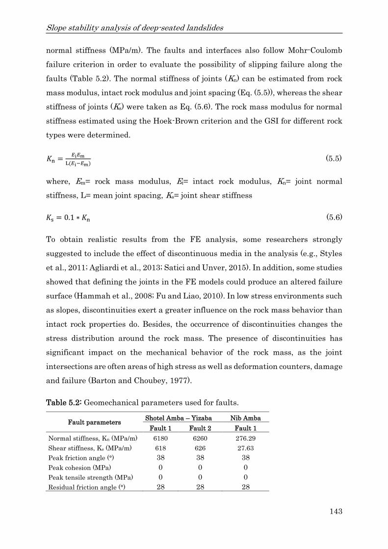
Slope stability analysis of deep-seated landslides
143
normal stiffness (MPa/m). The faults and interfaces also follow Mohr-Coulomb
failure criterion in order to evaluate the possibility of slipping failure along the
faults (Table 5.2). The normal stiffness of joints (Kn) can be estimated from rock
mass modulus, intact rock modulus and joint spacing (Eq. (5.5)), whereas the shear
stiffness of joints (Ks) were taken as Eq. (5.6). The rock mass modulus for normal
stiffness estimated using the Hoek-Brown criterion and the GSI for different rock
types were determined.
𝐾n =𝐸i𝐸m
L(𝐸i−𝐸m) (5.5)
where, Em= rock mass modulus, Ei= intact rock modulus, Kn= joint normal
stiffness, L= mean joint spacing, Ks= joint shear stiffness
𝐾s = 0.1 ∗ 𝐾n (5.6)
To obtain realistic results from the FE analysis, some researchers strongly
suggested to include the effect of discontinuous media in the analysis (e.g., Styles
et al., 2011; Agliardi et al., 2013; Satici and Unver, 2015). In addition, some studies
showed that defining the joints in the FE models could produce an altered failure
surface (Hammah et al., 2008; Fu and Liao, 2010). In low stress environments such
as slopes, discontinuities exert a greater influence on the rock mass behavior than
intact rock properties do. Besides, the occurrence of discontinuities changes the
stress distribution around the rock mass. The presence of discontinuities has
significant impact on the mechanical behavior of the rock mass, as the joint
intersections are often areas of high stress as well as deformation counters, damage
and failure (Barton and Choubey, 1977).
Table 5.2: Geomechanical parameters used for faults.
Fault parameters Shotel Amba – Yizaba Nib Amba
Fault 1 Fault 2 Fault 1
Normal stiffness, Kn (MPa/m) 6180 6260 276.29
Shear stiffness, Ks (MPa/m) 618 626 27.63
Peak friction angle (°) 38 38 38
Peak cohesion (MPa) 0 0 0
Peak tensile strength (MPa) 0 0 0
Residual friction angle (°) 28 28 28

Slope stability analysis of deep-seated landslides
144
Figure 5.4: (a) Slope cross-section and (b) discretized RS2 model of slope section
along the Shotel Amba section.
Figure 5.5: (a) Slope cross-section and (b) discretized RS2 model of slope section
along the Yizaba section.

Slope stability analysis of deep-seated landslides
145
Figure 5.6: (a) Slope cross-section and (b) discretized RS2 model of slope section
along the Nib Amba section.
Figure 5.7: (a) Slope cross-section and (b) discretized RS2 model of slope section
along the Wanza Beret section.
5.4 Results and discussion
5.4.1 Limit equilibrium analysis
The model outputs of the SLIDE2 2018 program for the Mohr-Coulomb material
types using grid search methods are shown in Figs. 5.8–5.10. The calculated FS

Slope stability analysis of deep-seated landslides
146
using the LE modeling are presented in Table 5.3. Between the four LE methods,
MPM resulted in the highest and JSM resulted in lowest FS but the differences
are marginal.
Table 5.3: Calculated FS using LE and FE methods without horizontal seismic
coefficient (h= 0).
Slope section
LEM Min. FS FEM
BSM JSM SM MPM Critical
SRF
Max. total displacement
(m)
Shotel Amba 2.26 2.16 2.27 2.27 1.51 23.2
Yizaba 2.59 2.52 2.59 2.59 1.87 15.6
Nib Amba 11.31 10.46 11.31 11.17 1.95 0.52
Wanza Beret 2.67 2.53 2.67 2.67 2.01 0.84
LEM= Limit Equilibrium Method; BSM= Bishop’s Simplified Method; JSM=
Janbu’s Simplified Method; SM= Spencer’s Method; MPM= Morgenstern-Price
Method; FEM= Finite Element Method
The calculated FS without seismic load ranged between a minimum of 2.16 and a
maximum of 11.31 (Table 5.3) and between a minimum of 0.92 to a maximum of
4.76 with seismic load for the various cases evaluated in this study (Table 5.4).
This clearly confirms that there is possibility of a sliding circular (rotational) slip
failure in the studied slopes. From the Shotel Amba to Wanza Beret cross-sections
(Figs. 5.4–5.7), the Shotel Amba cross-section attained the lowest FS of 0.92 with
seismic load and 2.16 without seismic load in the 2D limit equilibrium analysis as
shown in Fig. 5.8. It can be seen from Table 5.4 that the conventional method for
calculating the FS with seismic load is the JSM, which has a value of 0.92 in Shotel
Amba slope section. The highest FS is produced by MPM with a FS value of 1.02.
While BSM and Spencer methods produce almost similar FS values and failure
surfaces than the MPM, the JSM results in lower FS values and different failure
surfaces. The fact that JSM generates lower FS values is compulsory, since this
method is simpler than the BSM and Spencer methods, which are both more
rigorous methods. This leads to some differences in the FS values, though the
rigorous methods are often considered more reliable (Duncan and Wright, 1980).
From Table 5.3, it is observed that Nib Amba was the only slope section with very
high FS using the four LE methods. Among the slope sections, the Nib Amba slope

Slope stability analysis of deep-seated landslides
147
section differs very high from the other sections. The likely reason for that is when
computing the FS, the LEM didn’t consider joints act as initiation points of the
failure plane. In the slope section of Nib Amba there are weakness zones such as
faults and joints distributed along the lithologic boundary between the porphyritic
basalt and tuff.
Figure 5.8: 2D cross-section result from slide along the Shotel Amba section.
Figure 5.9: 2D cross-section result from slide along the Yizaba section.

Slope stability analysis of deep-seated landslides
148
Figure 5.10: 2D cross-section result from slide along the Wanza Beret section.
The FS values computed without seismic load via BSM, JSM, SM, and MPM are
all independently stable, while the FS values computed with seismic load indicate
slopes close to failure. This shows that the stability of the area becomes unstable
when there is a combination of saturation and seismic load. The upper part of the
slopes is dominated by colluvial deposits or intensively fractured rocks. In this
case, circular failure surfaces are expected.
5.4.2 Finite element analysis
The landslide stability of the selected slope sections was analyzed for shear strain,
slope stability and total displacement using the FE method (Figs. 5.11–5.14). The
RS2 software was utilized for constructing the slopes in Shotel Amba, Yizaba, Nib
Amba and Wanza Beret (Rocscience Inc. 2020). The models were divided into two
cases: (i) case 1 is the initial state in a static condition before the earthquake and
(ii) case 2 is the dynamic slope model incorporating a seismic event to simulate the
influence of an earthquake event on the selected slope sections (Figs. 5.11–5.14).
Based on the seismicity and the knowledge of the geology and tectonics, the region
can be broadly divided into three seismic sources (Mammo, 2005) namely the Afar
depression, the escarpment and the Ethiopian Rift system which are very near to
the study area. The study area is situated along the western margin of the Main
Ethiopia Rift (MER) which is tectonically active. The earthquake coefficient of
Peak Ground Acceleration (PGA) values for the Afar area ranging from 0.16g

Slope stability analysis of deep-seated landslides
149
(EBCS, 1995) to 0.75g (RADIUS, 1999) for the 0.01 annual probability. The inertia
forces due to earthquake shaking are represented by a constant horizontal force
(equal to the weight of the potential sliding mass multiplied by a coefficient) and
are commonly referred to as pseudo-static analysis (Pyke, 2002). In this work, the
horizontal earthquake coefficient of h= 0.3 is adopted for the pseudo-static slope
stability analysis as an average value for Shotel Amba and Wanza Beret and h=
0.2 for Yizaba and Nib Amba slope sections, as for the slope sections of Yizaba and
Nib Amba with the horizontal earthquake coefficient of h= 0.3 the FE model does
not converge. A slope is considered unstable in the SSR technique when its FE
model does not converge to a solution (within a specified tolerance). This shows
that the slopes are unstable as the seismic load increases.
Figure 5.11: (a) Finite element analysis for shear strain and (b) finite element
analysis for total displacement with maximum total displacement of 225 m along
the Shotel Amba section.

Slope stability analysis of deep-seated landslides
150
The slope sections have been analyzed under pseudo-static loading conditions
along with the gravitational forces using FEM-based RS2 software to model their
stability under a seismic event (Figs. 5.4–5.7 and Figs. 5.11–5.14). The RS2
program, on the other hand, accurately captured the complex failure pathway that
partly lay along the fault surfaces and partly pass through the intact rock (Figs.
5.11–5.14).
The slope failures in the rock masses in the FEM are more complex than in the
LEM and mainly controlled by joints and develop across surfaces formed by one or
more joint planes (Wyllie and Mah, 2004). This is in agreement with previous
studies (e.g., Styles et al., 2011; Agliardi et al., 2013; Satici and Unver, 2015).
Results for the dynamic case are presented in Figs. 5.11–5.14, the total
displacement and maximum shear strain contours exhibit a potential shear failure
surface and the critical SRF or FS for the cases evaluated in this study range
between a minimum of 0.58 and a maximum of 1.03 (Table 5.4). This indicates that
the slope stability is low due to the weak rock mass. On the other hand, for the
results from the static case the critical SRF ranged between a minimum of 1.51
and a maximum of 2.01 (Table 5.3). The slope at Shotel Amba showed that the SRF
of the slope without seismic load is 1.51, whereas the SRF of slope with seismic
load is 0.58 (Fig. 5.11). The results from this simulation are shown in Figs. 5.11–
5.14 which depicts the total displacement and maximum shear strain contours. In
comparing the resulting slope failure surfaces using the LE and FE analysis, a
large difference in the shape of the failure surface was noted. However, the slope
failure surfaces of the Wanza Beret slope section resulting from the LE methods
are best-matched to the critical failure surfaces resulting from the FE method
(Figs. 5.10 and 5.14). The critical failure surfaces resulting from the LE analyses
were perfectly circular due to the selected search criterion (Figs. 5.8–5.10), the FE
method produces a near-circular zone of failure surfaces near the toe of the slope
(Figs. 5.12 and 5.14). The FE analyses produce a better-defined failure path than
the LE analyses. The FEM be able to automatically locate the failure regions,
thereby not requiring the prior assumptions on the failure surface as compared to
the LEM.

Slope stability analysis of deep-seated landslides
151
Table 5.4: Calculated FS using LE and FE with horizontal seismic coefficient (h=
0.2 and 0.3).
Slope
section
Seismic
load LEM Min. FS FEM
h BSM JSM SM MPM Critical
SRF
Max. total displacement
(m)
Shotel Amba 0.3 0.98 0.92 1.01 1.02 0.58 225
Yizaba 0.2 1.06 1.02 1.07 1.07 0.89 36.1
Nib Amba 0.2 4.76 4.39 4.75 4.62 1.03 1.3
Wanza Beret 0.3 1.23 1.15 1.25 1.24 0.84 1.9
LEM= Limit Equilibrium Method; BSM= Bishop’s Simplified Method; JSM=
Janbu’s Simplified Method; SM= Spencer’s Method; MPM= Morgenstern-Price
Method; FEM= Finite Element Method
Further, using the FE method, it is possible to compute the total displacement of
rock and soil from the input data. Figures 5.11–5.14 show the critical failure
surface and shear strain developed in the slope at the time of failure. The areas of
maximum shear strain indicate the likely failure pathway that would develop
through the modeled rock mass. The maximum shear strain along the critical
failure surface is found to be 18.6 in Shotel Amba and 2.35 in Yizaba slope sections.
The maximum total displacement in Shotel Amba and Yizaba are found to be
225 m (Fig. 5.11) and 36.1 m (Fig. 5.12), respectively. This is in agreement with the
findings of (Kropáček et al., 2015), who found that topographic profiles show that
the maximum estimated thickness of the active main landslide body is about 150–
200 m. The maximum total displacement in the Shotel Amba and Yizaba slope
sections coincide with the results of the topographic profiles (Figs. 11 and 12). The
maximum stress concentration along with the critical FS presumes the possibility
of a middle zone collapse and subsequent failure of the slope.

Slope stability analysis of deep-seated landslides
152
Figure 5.12: (a) Finite element analysis for shear strain and (b) finite element
analysis for total displacement with maximum total displacement of 36.1 m along
the Yizaba section.
In the slope section of Yizaba, shear elements are noticeable along the circular
failure surface originating from the tension zone and continuing till the toe of the
slope (Fig. 5.12). For the FS, the largest displacements are in red and the minor
ones in blue. It can be deduced that the mechanism of failure is a block sliding with
a displacement produced by the low strength of colluvial deposits (poorly sorted
clayey sand to silty sand) and tuff. In the slopes Shotel Amba and Yizaba the
middle zone of the slope moves to the right and a crack is formed in the middle of
the slope, showing that deep-failure mechanism (Figs. 5.11 and 5.12). It is also
observed that the failure surface and the location estimated by the numerical
method match with the field observation (Fig. 5.2f). There are many tension cracks
which are developed in the area, and these tension cracks are indications for
probable some more slides to occur in the near future (Fig. 5.2). A factor of safety

Slope stability analysis of deep-seated landslides
153
of 1.03 has been attained through the finite element analysis of the Nib Amba slope
with seismic load (Fig. 5.13).
Figure 5.13: (a) Finite element analysis for shear strain and (b) finite element
analysis for total displacement with maximum total displacement of 1.3 m along
the Nib Amba section.
The computed FS with seismic load for the cases evaluated in this study is less
than one except for Nib Amba (Fig. 5.13) but which is very close to one. So, there
is a risk of failure of all slopes during an earthquake. The calculated FS of Nib
Amba slope section using FEM becomes less than one when the seismic load
increases. The findings indicated that differences between the LE and FE methods
are evident when a heterogeneous and complex slope geometry is analyzed. The
calculation of the FS shows a significant difference between the two approaches.
The FS from LEM with seismic load ranged between 0.92 and 4.76, while critical
SRF from finite element analysis were between 0.58 and 1.03 for 2D FEM
simulations. Among the slope sections, the Nib Amba slope section differs very

Slope stability analysis of deep-seated landslides
154
strongly from the other sections. From this perspective, the case study shows that
tectonic activity plays a well-defined role in promoting landslides with seismicity
as a possible predisposing factor or even a trigger, as the area is in close proximity
to the most seismically active regions in the country (Mebrahtu et al., 2020b). The
critical SRF from FEM are significantly lower than the FS from LEM. The low
value of SRF emphatically suggests that the rock slope can be vulnerable to failure
under influence of any triggering force.
Figure 5.14: (a) Finite element analysis for shear strain and (b) finite element
analysis for total displacement with maximum total displacement of 1.9 m along
the Wanza Beret section.
The results of the FEM showed that from the static and dynamic analysis, it has
been concluded that the slope sections have the lowest FS compared to the
calculated FS using the LEM. At the critical SRF, the slope material undergoes
significant strength degradation as the failure surface is formed by coalescing
fractures, which converge with the kinematically feasible release plane. Any
Slope stability analysis of deep-seated landslides
155
further increment in SRF value accelerates the slide mass movement which causes
an increased total displacement of slope mass material.
The lithologic units of the study area are anisotropic in their behavior and their
stress-strain behavior is quite variable, due to the presence of volcanic ash. The
elasto-plasticity behavior of the ash due to the presence of water poses a serious
threat during the periods of prolonged and heavy rainy seasons. The SRF due to a
rise in pore-water pressure might lead to slope failure. The slope stability analysis
using the LE and FE methods indicate that the area is highly susceptible to sliding
when they get moist. The springs observed at the base of the slope provide the pore
pressure regime, which determines critical conditions for the study area slope
stability. This results in the build-up of high hydrostatic pressure and results in a
reduction of effective normal stresses in the rock mass giving rise to landslides.
Moreover, the concave shape of a slope can enhance the convergence of
groundwater flow into the landslide area since water tables are relatively high in
such slopes (Mebrahtu et al., 2021).
5.5 Conclusions
In this paper, a study on both LE and FE methods for slope stability is performed.
The results of the stability analysis show that the slope stability of landslides in
the study area strongly depends on the saturation conditions and seismic load.
While the saturation conditions were assumed constant in the shown simulations,
it is evident that a pore pressure increase would further reduce the FS. The
importance of faults in hydraulic gradient of the groundwater and their influence
on the slope stability in the study area has previously been discussed extensively
(Mebrahtu et al., 2020a; Mebrahtu et al., 2020b; Mebrahtu et al., 2021). The
strength reduction technique within a framework of elasto-plasticity allows to
magnify the deformations and failure mechanisms to emerge in a natural way. The
FS obtained using LE and FE methods without seismic load ranged between a
minimum of 2.16 and a maximum of 11.31 and between a minimum of 1.51 to a
maximum of 2.01, respectively. Whereas the calculated FS using LE and FE
methods with seismic load ranged between a minimum of 0.92 and a maximum of
4.76 and between a minimum of 0.58 to a maximum of 1.03, respectively. In

Slope stability analysis of deep-seated landslides
156
particular, the slope sections after the earthquake event were considered as
unstable with a SRF between 0.58 and 1.03.
It was found that the FS results from LE and FE methods are significantly
different. Since the LE and FE methods employ completely different numerical
techniques, they did not produce very similar FS values and failure surfaces for
the studied slopes. According to the results of the LE analyzes, the slopes are
classified as stable, but as a result of the FE analysis, the slopes are unstable. From
the FE analysis, it can be inferred that the study area is critically unstable and
any small scale disturbance will further reduce the FS and cause failure,
particularly when the area experience heavy rainfalls or earthquakes. The
presence of multiple sets of joints and faults in rock masses and intense rainfall
further accelerate the slope failure. The result of the stability analysis shows that
the slope stability of landslides in the study area strongly depends on the
saturation conditions and seismic load. Hence, the major landslide that occurred
in September 2005 is most probably triggered by such combination of saturation
and earthquake activities.
From the stability analysis results, both the LE and FE methods produce deep-
seated failure surfaces through the foundation of colluvial deposits. It is also
observed that the failure surface and location estimated by the numerical method
match with the field observation. The strength reduction method is well-suited for
complex geometry and further representative normal stress distributions,
subsequent generating consequential FS values. The FEM generates a FS values
less than 1 for almost all the slope sections, although those are over 1 for the LEM.
In general, the FS computed from the stress-strain behavior of the rock and soil
using FE method is more realistic and provides even more accurate FS results
when a heterogeneous and complex slope geometry is analyzed. From the finding,
it is concluded that the studied slope stability evaluation methods should be
obtained collectively as part of a larger slope stability analysis to determine the
resultant FS. Furthermore, this study states that differences between the FE and
LE methods are evident when a heterogeneous slope is analyzed. Especially when
faults are involved and act as initiation points of the failure plane, the LEM tends

Slope stability analysis of deep-seated landslides
157
to overestimate the slope stability significantly. Both methods show a significant
decrease in the obtained FS values for the study area when the seismic load is
considered but LEM always results in higher FS values. Though, for the static
assessment without a seismic effect, the interpretation of LEM and FEM might not
vary so much, as both methods indicate the slopes as stable with FS values around
two. Therefore, it is a useful practice to employ different tools to reach a conclusion
about the stability state of slopes presenting with highly variable rock mass
conditions. In general, field investigations indicate that several different failure
mechanisms are superimposed on the deep-seated Debre Sina landslide. The
laboratory tests reveal that the lowest value of peak strength is from less
compacted tuff and prone to sliding. The tuff layers with low peak strength are
initiation points for the sliding surfaces. The FEM is found more applicable for
stability assessment because of the complex geometry, heterogeneous material and
the failure-dominating faults in the study area. The studied slopes are initially
close to failure and increased pore pressure or seismic load are very likely triggers.
Authors’ contributions
TKM as a first author carried out the fieldwork, collected rock samples, did the
laboratory analysis and interpretation of the data, conducted the numerical
simulations and wrote the manuscript while taking comments from TH, SW and
MA, and finalized the manuscript. TH and MA have been involved in a detailed
review of the manuscript prior to submission. All authors gave their approval of
the final manuscript to be published.
Acknowledgments
The first author would like to thank the German Academic Exchange Service
(DAAD) for the scholarship grant to pursue the PhD study. This work was
supported by the Ruhr University Research School PLUS, funded by Germany's
Excellence Initiative (DFG GSC 98/3).

Summary and future research perspectives
158
Chapter 6
6 Summary and future research perspectives
6.1 Summary
Landslides are a common phenomenon in the central highlands and Rift
escarpments of Ethiopia, which brought a heavy impact on agricultural land,
dwellers and infrastructure, and often lead to the displacement and death of
people. The Debre Sina area is one of the most tectonically active areas located
along the western margin of the Afar depression, which is frequently affected by
landslides. Despite that, urban and rural development is currently active in almost
all constricted valleys as well as on the imposing cliffs without prior site
investigation and thereby exposing these areas to landslide problems. In this
chapter the findings obtained in the four chapters (chapters 2 to 5) and their
implications are discussed and summarized. The main results and conclusions
related to the overall controlling parameters of deep-seated landslides, the
processes leading to the triggering of a landslide, and the failure mechanisms in
the study area are summarized below.
Geologically, the study area is represented by aphanitic basalt-porphyritic-
agglomerate, ignimbrite-tuff-volcanic ash, porphyritic basalt-scoriaceous
agglomerate, Tarmaber basalt, upper ignimbrite, colluvial and alluvial deposits.
The presence of highly fractured porphyritic-agglomeratic basalt, highly shattered
ignimbrite and volcanic ash, which are all prone to water absorption and
susceptible to slaking, was identified as one of the reasons for a high concentration
of landslides and main triggering factors of reactivation in the observed cases. The
results obtained during this study show that the inherent variation in the physical
property of the lithologic sequence and their structures influence slope stability.
The study area experiences high tectonic activity with intense fracturing due to its
location at the western margin of the Main Ethiopian Rift. The area has been
affected by N–S, E–W, NNE–SSW, NE–SW, NW–SE, NNW–SSE, and WSW–ENE

Summary and future research perspectives
159
major trends of faults. Among these, the N–S and E–W trends are widespread in
the area with the highest frequency. The N–S trending normal faults are arranged
in a stepwise system towards east, which controls the morphology of the slope of
the Rift margin escarpment. The landslides displacement is orthogonal to the
NNE–SSW, and N–S striking normal fault systems that are affected by NW and
NE striking trans-tensional components. The interaction of these fault systems
produced a complex displacement across and along the escarpment, manifesting
oblique continental rifting. The intense fracturing and presence of faults favor an
easy movement along existing fault planes during saturation of the rocks or soils
and during seismic events or a combination of both conditions. The kinematic
evaluation of the faults data and slope faces using Dips v 7.0 software revealed
that the major landslide that took place on 13 September 2005 in the Yizaba Wein
locality was mainly controlled by NNE–SSW, NNW–SSE, and WSW–ENE
trending faults. The kinematic analysis shows that the rock slope has a higher
probability of failure in the wedge sliding failure mode (66.67%) compared to
planar sliding (33.33%). The faults in the area are not only weak zones, but also
mostly characterized by deeper weathering and higher potential for concentrated
groundwater flow, which can act as a lubricant and produce water pressures
causing landslides.
The geomorphological survey shows that various landforms have been identified in
the area, including long term tectonic, deep-seated slope failures, deep fluvial
dissection and slope forms. The morphology of the area is especially conditioned by
numerous rotational slides, translational slides, rockfalls and toppling, rock slides,
debris slides, and earth flows. It is observed that the morphology in combination
with the tectonic assemblage and the intense weathering processes strongly favors
the mass movement. The geomorphological analysis also showed that the complex
landslide sloped surfaces in the detachment zone are associated with a hummocky
and step-like morphology as a result of successive or retrogressive sliding. Overall
assessment of the morphometric analysis revealed that the slopes ranging from 10°
to 40°, with an elevation of 1800–2500 m and aspect to east and southeast, are
highly prone to sliding.

Summary and future research perspectives
160
The depth of investigations from the presented seismic refraction survey was
attained with a maximum of 75 m. The seismic refraction study revealed zones of
overburden material from top to bottom, consisting of: clay, loosely cemented
colluvial sediments and highly weathered material (Vp 1000 m/s) with a
thickness of 7–15 m, highly weathered agglomeratic basalt (1000–1500 m/s) up to
30 m thick, highly to moderately fractured porphyritic basalt, ignimbrite,
rhyolite/trachyte and volcanic ash (1500–2500m/s) with a maximum 30 m thick,
moderately to slightly fractured ignimbrite, rhyolite/trachyte and basalt (2500–
3500m/s) 40–50 m thick and very strong, massive, fresh rock/ bed rock (Vp 3500
m/s). The depth to very fresh sound bedrock ranges between 45 m and 75 m. These
units are highly susceptible to sliding when it gets moist, because the volcanic
ashes are prone to slaking and acts as lubricant material. The seismic refraction
data shows that the currently active landslide is superimposed by a larger slide
including parts of the bedrock. The slip surface generally coincides with the 2000
m/s isoline due to the presence of highly fractured and saturated nature of the
underlying rocks. The upper layers of unconsolidated deposits and porphyritic-
agglomeratic basalt rocks experiences significant water transit towards the deeper
layer of ignimbrite-volcanic ash. However, the pyroclastic sediments are impeding
the vertical percolation of rainwater due to their low permeability and hence force
the rainwater to flow laterally. The study shows that tectonic activity plays a well-
defined role in promoting landslides with seismicity as a possible predisposing
factor and by determining the lines of weakness along which the landslides may
have developed. In general, the geophysical data indicates that the area is covered
by unconsolidated sediments and highly decomposed and weak volcanic rocks
which are susceptible to sliding when they get moist.
The hydrogeological conditions of the terrains are generally favourable for the
development of seepage forces within the pyroclastic sediments (tuff and pumice
horizons) and unconsolidated deposits during periods of rainfall. The residence
time is short, the soil/rock-water interaction is low and the water is barely
mineralized in the highland and intermediate regions. Therefore, it is possible to
conclude that the main cause of the landslide is not because of active soil/rock-
water interaction. It is rather because of the steep slope topography and the

Summary and future research perspectives
161
pressure formed during precipitation, which leads to an increase in the weight of
the loose and weathered materials (increasing its shear stress) and loses its shear
resistance which finally results in mass failure or landslide.
Three groundwater groups have been identified from the preliminary HCA based
on major-ion chemistry (Na+, K+, Mg2+, Ca2+, HCO3–, SO4
2–, F–, Cl–) of the water
samples collected in this study. Group I samples are collected from basaltic and
scoriaceous aquifers in the highlands bounding the rift valley areas are
characterized by low EC (72–222 µS/cm) and low concentrations of all the major
ions. This indicates that groundwater in the highland areas is getting recharge
from rainwater. Group II samples with a similar lower EC (115–465 µS/cm) and
low concentrations of all the major ions are collected from highly fractured and
shattered ignimbrite, rhyolite, trachyte associated with basalt close to the
escarpments. However, they have relatively higher concentrations of Na+, K+, Cl–
and SO42– as compared to group I, which is mainly related to the solution or
interaction between water and secondary minerals or clay that precipitate into
faults. Group III samples are collected from the lower altitude areas (below 1500
m asl) in the eastern and northeastern parts of the study area which is extensively
covered with volcanic ash-dominated units and sporadic colluvial-alluvial deposits.
In these litho-units, the groundwater movement is slow, which together with the
presence of soluble minerals, enhances the effects of rock-water interaction giving
rise to relatively higher concentrations of Na+, K+, Cl– and SO42–. The EC values of
the groundwater samples within this group is between 215 and 573 µS/cm and
increase towards the Shewa Robit valley. It indicates that there is intermediate to
deep groundwater circulation and relatively higher residence time of the
groundwater.
The lithostratigraphic, geomorphologic, isotopic and hydrochemical evidences have
indicated that two groundwater flow systems (shallow/local and intermediate-
deep) exist in the study area. The shallow groundwater flow is mainly localized to
the highland areas and adjacent escarpments and its water table is a subdued
replica of the surface topography. The intermediate-deep groundwater flow is
strongly influenced by the lithostratigraphy and the major faults in the area rather

Summary and future research perspectives
162
than the surface geomorphology. There are four major groundwater types in
general hydrochemical facies of the Debre Sina area identified as Ca–Mg–HCO3,
Ca–HCO3, Ca–Mg–Cl–SO4 and Na–HCO3. The low TDS and bicarbonate types (Ca–
Mg–HCO3 and Ca–HCO3) of groundwater chemistry indicate a fast hydrogeological
regime receiving a relatively high amount of precipitation with infiltrated water
flowing in the fissured and disturbed aquifers developed in various volcanic rocks
and intercalated sediments. The chemical and isotopic characterization indicate
that shallow to intermediate aquifers cause groundwater flow into the landslide
mass, influencing long-term groundwater level fluctuations underneath the
landslide and, as a consequence, its stability.
The cross plot of δ18O and δ2H values of the water samples shows that local
precipitation is the major source of recharge to the aquifers of the area. The stable
isotope results indicate that rainfall is one of the main triggering factors of the
slope instability in the area associated with degrading rock mass strength and
increase of the weight of the slope mass, i.e. increasing the pull of gravity. The EC
versus oxygen isotope (δ18O) also shows a strong correlation which can indicate the
dominance of locally recharged shallow groundwater flow system in the area. The
hydrogeological conditions of the terrains are generally favourable for the
development of seepage forces within the pyroclastic sediments (tuff and pumice
horizons) and unconsolidated deposits during periods of rainfall. This indicates
that precipitation is one of the potential triggering factors for the slope failure in
the Debre Sina area. Besides, the concave shape of the terrain is enhancing the
convergence of groundwater flow into the landslide area. The relationship between
rainfall and landslide events indicates that deep-seated failures prevail after a
longer period of intensive rainfall. The presence of multiple sets of joints in rock
masses and intense rainfall further accelerate the slope’s failure.
It is evident that a pore pressure would further reduce the FS and influence the
slope stability. The calculation of the FS shows a significant difference between the
LE and FE methods. The FS from LEM with seismic load ranged between 0.92 and
4.76, while critical SRF from FEM were between 0.58 and 1.03 for 2D FEM
simulations. The minimum FS is calculated to be 0.58 for the Yizaba slope section

Summary and future research perspectives
163
using the FEM for the saturated condition with seismic load, which has a similar
condition to the massive landslide of September 2005. This shows that the stability
of the area becomes unstable when there is a combination of saturation and seismic
load. This means that tectonic activity plays a well-defined role in promoting
landslides with seismicity as a possible predisposing factor or even a trigger, as the
area is in close proximity to the most seismically active regions in the country. The
critical SRF from FE analysis are significantly lower than the FS from LE analysis.
The low value of SRF emphatically suggests that the rock slope can be vulnerable
to failure under influence of any triggering force. Both methods show a significant
decrease in the obtained FS values for the study area when the seismic hazard is
considered but LEM always results in higher FS values. From the FE analysis, it
can be inferred that the study area is critically unstable and any small scale
disturbance will further reduce the FS and cause failure, particularly when the
area experiences heavy rainfalls or earthquakes. The numerical analysis showed
that the presence of joints in rock masses considerably affects the slope safety
factors. From the finding, it is concluded that the FEM-based slope stability
analysis with the SSR technique is found more applicable for stability assessment
because of the complex geometry, the heterogeneous material and the failure-
dominating faults in the study area. In general, the main controlling factors for
landslide problems in the area are the intensive weathering of the rocks; the
prominent geological structures; steep slope-gradient; the groundwater pressure
developed during precipitation; and the presence of low permeability beds which
force the percolating water to flow laterally.
6.2 Future research perspectives
The following recommendations are made for further action and landslide research
in the Debre Sina area in particular and the highlands of Ethiopia in general. Since
rainfall and earthquake-induced landslides are the major failure triggers in the
northwestern rift escarpment of Ethiopia, monitoring rainfall (such as intensity,
duration and antecedent) and groundwater fluctuation, is vital for proper landslide
hazard prediction and prevention. This could be used to develop early warning
system for mass movement hazards. For the future, comprehensive data

Summary and future research perspectives
164
generation using borehole drilling, periodic monitoring of the rate of movement
and additional geophysical data collection using different techniques must be
conducted to have a wider and more comprehensive view of the area from a
mechanical and geological points of view. In order to improve understanding of
triggering factors of large-scale rock slides, further research on slope stability
analyses should be performed using field monitoring and numerical modelling
based on 3D finite elements. The study area is in close proximity to one of the most
seismically active regions in the world. Therefore, evaluating seismic activity and
its concomitant impacts on deep-seated landslides to obtain a complete view of the
area from a tectonic perspective should be further explored. As there are intensive
urban and infrastructural developments taking place along hills and rugged
mountains in the study area and surroundings, serious attention is also required
to consider the seismic hazard in the area during planning, design, and
construction phases. Much of the mountainous terrains of central highlands of
Ethiopia remain highly fragile in terms of mass movements; thus, any external
factors such as heavy rainfall or excavation could lead to slope failure. Prior to any
development planning, it is advisable to undertake proper landslide hazard
assessment and risk analysis in certain areas. Landslide and landslide-related
hazards are one of the major natural hazards causing tremendous losses in the
country but no attention is given at the moment. So far, the economic, social and
environmental impacts of mass movement hazards in Ethiopia have not been
widely recognized as a problem of national concern. Thus, a continuous research
work on landslide and related hazards in Rift margin and highland terrains is
highly recommended to increase the level of understanding on both local and
regional scales. This would be aid to finally reduce the damages and risks
prevailing on intense environmental degradation and failure of major
infrastructures. There are no historical records of landslides that indicate time of
occurrences, its magnitude, travelling distances, triggering factor, and associated
damage. It is, therefore, crucial to establish a landslide inventory data at least in
the major areas known for their landslide hazard in the country to properly address
and predict the time of occurrences, expected magnitude and travel distances as
well as associated damages.

Declaration of authorship
165
Declaration of authorship
Chapter 2
Citation: Tesfay Kiros Mebrahtu, Bedru Hussein, Andre Banning, Stefan
Wohnlich, 2020a. Predisposing and triggering factors of large-scale landslides in
Debre Sina area, central Ethiopian highlands. Bull of Eng Geol Environ. 80:1–19.
DOI: 10.1007/s10064-020-01961-1.
Declaration of authorship: Tesfay Kiros Mebrahtu (TKM) as first author, was
responsible for the whole process including fieldwork, data collection, database
preparation, data analysis and interpretation. TKM also wrote the manuscript
including comments from Bedru Hussien (BH), Andre Banning (AB) and Stefan
Wohnlich (SW) on the data interpretation and presentation. AB was involved in a
detailed review of the manuscript prior to submission. TKM finalized the
manuscript for journal submission after a consensus is reached with BH, AB and
SW. All authors gave their approval of the final manuscript to be published.
Chapter 3
Citation: Tesfay Kiros Mebrahtu, Michael Alber, Stefan Wohnlich, 2020b. Tectonic
conditioning revealed by seismic refraction facilitates deep-seated landslides in the
western escarpment of the Main Ethiopian Rift. Geomorphology 370, 107382. DOI:
10.1016/j.geomorph.2020.107382.
Declaration of authorship: TKM conducted the field investigations, data analyses
and interpretation and wrote the manuscript while receiving comments from
Michael Alber (MA) and SW, and finalized the manuscript for journal submission
after a consensus was reached with MA and SW. All authors gave their approval
of the final manuscript to be published.
Chapter 4
Citation: Tesfay Kiros Mebrahtu, Andre Banning, Ermias Hagos, Stefan Wohnlich,
2021. The effect of hydrogeological and hydrochemical dynamics on landslide

Declaration of authorship
166
triggering in the central highlands of Ethiopia. Hydrogeol J 29, 1239–1260. DOI:
10.1007/s10040-020-02288-7.
Declaration of authorship: TKM conducted the fieldwork, collected water samples,
developed the method and obtained all results in consultation with all authors. The
manuscript was written by TKM and reviewed by AB, Ermias Hagos (EH) and SW.
AB, EH and SW were involved in a detailed review of the manuscript prior to
submission. All authors gave their approval of the final manuscript to be published.
Chapter 5
Citation: Tesfay Kiros Mebrahtu, Thomas Heinze, Stefan Wohnlich, Michael Alber,
(submitted). Slope stability analysis of deep-seated landslides using Limit
Equilibrium and Finite Element methods under static and seismic load in Debre
Sina area, Ethiopia.
Declaration of authorship: TKM carried out the fieldwork, collected rock samples,
did the laboratory analysis and interpretation of the data, conducted the numerical
simulations and wrote the manuscript while taking comments from Thomas
Heinze (TH), SW and MA, and finalized the manuscript. TH and MA have been
involved in a detailed review of the manuscript prior to submission. All authors
gave their approval of the final manuscript to be published.

References
167
References
Abay, A., Barbieri, G. (2012). Landslide susceptibility and causative factors
evaluation of the landslide area of Debre Sina, in the southwestern Afar
escarpment, Ethiopia. J Earth Sci Eng 2:133–144.
Abebe, B., Acocella, V., Korme, T., Ayalew, D. (2007). Quaternary faulting and
volcanism in the Main Ethiopian Rift. J Afr Earth Sci 48:115–124.
Abebe, B., Dramis, F., Fubelli, G., Mohammed, U., Asfawossen, A. (2010).
Landslides in the Ethiopian highlands and the rift margins. J Afr Earth Sci
56:131–138.
Abebe, T., Mazzarini, F., Innocenti, F., Manetti, P. (1998). The Yerer-Tullu Wellel
volcano tectonic lineament: a transtensional structure in central Ethiopia
and the associated magmatic activity. J Afr Earth Sci 26:135–150.
Abramson, L.W., Lee T.S., Sharma, S., Moyce, G.M. (1996). Slope stability and
stabilization methods. John Wiley & Sons Inc, New York, pp. 629.
Agliardi, F., Crrosta, G.B., Zanchi, A., Ravazzi, C. (2009). Onset and timing of deep-
seated gravitational slope deformations in the eastern Alps, Italy.
Geomorphology 103:113–129.
Agliardi, F., Crosta, G.B., Meloni, F., Valle, C., Rivolta, C. (2013). Structurally-
controlled instability, damage and slope failure in a porphyry rock mass.
Tectonophysics 605:34–47.
Agostini, A., Bonini, M., Corti, G., Sani, F., Manetti, P. (2011). Distribution of
quaternary deformation in the central Main Ethiopian Rift East Africa.
Tectonics 30.
Alemayehu, L., Gerra, S., Zvelebil, J., Šíma, J. (2012). Landslide investigations in
Tarmaber, Debre Sina, North Shewa Zone, Amhara Regional State,
AQUATEST a.s.
Aleotti, P., Chowdhury, R. (1999). Landslide hazard assessment: summary review
and new perspectives. Bull. Eng. Geol. Environ. 58 (1):21–44.
Alexander, D., Formichi, R. (2006). Tectonic causes of landslides. Earth Surf.
Process. Landf. 18:311–338.

References
168
Almond, D.C. (1986). Geological evolution of the Afro-Arabian dome.
Tectonophysics 131:301–332.
Ambrosi, C., Crosta, G.B. (2006). Large sackung along major tectonic features in
the Central Italian Alps, Eng. Geol., 83, 183–200.
Asrat, A., Eshete, G., Tadesse, T., Getaheh, W., Fekede, K. (1996). Land mass
movement of November 10, 1994 in Goffa District, Northern Omo zone,
Southern Ethiopia. In: Abstracts, Third Ethiopian Geosceince and Mining
Engineering Congress, 15–17 November 1996, Addis Ababa, Ethiopia, pp.
18–19.
Ayalew, L. (1999). The effect of seasonal rainfall on landslides in the highlands of
Ethiopia. Bull Eng Geol Environ 58:9–19.
Ayalew, L. (2000). Factors affecting slope stability in the Blue Nile basin.
Landslides in Research, Theory and Practice, Proceedings of the 8th
International Symposium on Landslides, 26–30 June 2000 (Cardiff: Thomas
Telford), pp. 101–106.
Ayalew, L., Yamagishi, H. (2002). Landsliding and landscape development; the
case of northern Ethiopia. In: Proceedings of the international congress
intrapraevent 2002, Matsumoto, Japan, pp. 595–606.
Ayalew, L., Yamagishi, H. (2004). Slope failures in the Blue Nile Basin, as seen
from landscape evolution perspective. Geomorphology 57:95–116.
Ayele, A. (2009). The September 19, 2009, MI 5.0 earthquake in the Ankober area:
lessons for seismic hazard mitigation around Addis Ababa. 6th Annual
African Arry workshop, South Africa, 2010.
Ayele, A., Keir, D., Ebinger, C.J., Wright, T., Stuart, G.W. (2009). The September
2005 mega-dyke emplacement in the Manda-Hararo (Afar) nascent oceanic
rift. Geophys Res Lett, 36, L20306.
Ayenew, T. (2005). Major ions composition of the groundwater and surface water
systems and their geological and geochemical controls in the Ethiopian
volcanic terrain. SINET Ethiop J Sci 28:171–188.
Ayenew, T., Barbieri, G. (2005). Inventory of landslides and susceptibility mapping
in the Dessie area, northern Ethiopia. Eng Geol 77:1–15.

References
169
Ayenew, T., Kebede, S., Alemyahu, T. (2008). Environmental isotopes and
hydrochemical study applied to surface water and groundwater interaction
in the Awash River basin. Hydrol Processes 22:1548–1563.
Ayob, M., Kasa, A., Sulaiman, M.S., Miniandi, N.D., Yusoff, A.H. (2019). Slope
stability evaluations using limit equilibrium and finite element methods. Int
J Adv Sci Technol 28:27–43.
Baker, B.H., Mohr, P.A., Williams, L.A.J. (1972). Geology of the Eastern Rift
System of Africa. Geol. Soc. Amer. Spec. Paper 136, pp. 67.
Bar, N., Yacoub, T.E., McQuillan, A. (2019). Analysis of a large open pit mine in
Western Australia using finite element and limit equilibrium methods. 53rd
US Rock Mech Symp, American Rock Mechanics Association, Alexandria,
paper ARMA 19–A–30.
Barton, N. (1972). A model study of rock-joint deformation. Int. J. Rock Mech. Min.
Sci. Geomech. Abstr., 579–602.
Barton, N. (1976). The shear strength of rock and rock joints. Int. J. Rock Mech.
Min. Sci. & Geomech. Abstr. 13:1–24.
Barton, N., Choubey, V. (1977). The shear strength of rock joints in theory and
practice. Rock Mechanics and Rock Engineering 10.1:1–54.
Beccaluva, L., Bianchini, G., Natali, C., Siena, F. (2009). Continental flood basalts
and mantle plumes: a case study of the Northern Ethiopian plateau. Journal
of Petrology 50 (7), 1:377–1403.
Bell, F.G. (1999). Geological hazards: their assessment, avoidance, and mitigation.
E & FN Spon, Routledge, London, pp. 648.
Bell, R., Kruse, J.E., Garcia, A., Glade, T., Hördt, A. (2006). Subsurface
investigations of landslide using geophysical methods-geoelectrical
applications in the Swabian Alb (Germany). Geographica Helvetica, 61:201–
208.
Beyene, A., Abdelsalam, M.G., (2005). Tectonics of the Afar Depression: a review
and synthesis. Journal of African Earth Sciences 41:41–59.
Bichler, A., Bobrowsky, P., Best, M., Douma, M., Hunter, J., Calvert, T., Burns, R.
(2004). Three-dimensional mapping of a landslide using a multi-geophysical
approach: the Quesnel Forks landslide. Landslides 1:29–40.

References
170
Bishop, A.W. (1955). The use of the slip circle in the stability analysis of slopes.
Geotechnique 5(1):7–17.
Boccaletti, M., Bonini, M., Mazzuoli, R., Abebe, B., Piccardi, L., Tortorici, L. (1998).
Quaternary oblique extensional tectonics in the Ethiopian Rift (Horn of
Africa). Tectonophysics, 287:97–116.
Bogaard, T.A., Antoine, P., Desvarreux, P., Giraud, A., Van Asch, W.J. (2000). The
slope movements within the Mondorès graben (Drôme, France): the
interaction between geology, hydrology and typology. – Eng. Geol., 55:297–
312.
Bogoslovsky, V.A., Ogilvy, A.A. (1977). Geophysical methods for the investigation
of landslides. Geophysics 42:562–571.
Bois, T., Bouissou, S., Guglielmi, Y. (2008). Influence of major inherited faults
zones on gravitational slope deformation: a two-dimensional physical
modelling of the LaClapière area (Southern French Alps). Earth Planet. Sci.
Lett. 272:709–719.
Bonini, M., Corti, G., Innocenti, F., Manetti, P., Mazzarini, F., Abebe, T. and
Pecskay, Z. (2005). Evolution of the Main Ethiopian Rift in the frame of Afar
and Kenya rifts propagation. Tectonics, 24, TC1007.
Borgatti, L., Corsini, A., Barbieri, M., Sartini, G., Truffelli, G., Caputo, G., Puglisi,
C. (2006). Large reactivated landslides in weak rock masses: a case study
from the Northern Apennines (Italy). Landslides 3:115–124.
Brotzu, P., Morbidelli, L., Piccirillo, E.M., Traversa, G. (1986). Rift structure
development and magma composition in East Africa (South-East Ethiopia
and East Kenia). Mem. Sot. Geol. Ital., 31:401–413.
Bruno, F., Marillier, F. (2000). Test of High-resolution Seismic Reflection and
Other Geophysical Techniques on the Boup Landslide in the Swiss Alps.
Surveys in Geo-physics, Vol. 21. pp. 333–348, No. 4, 2000.
Brunsden, D. (1999). Some geomorphological considerations for the future
development of landslide models. Geomorphology 30:13–24.
Bucci, F., Cardinali, M., and Guzzetti, F. (2013). Structural geomorphology, active
faulting and slope deformations in the epicenter area of the MW 7.0, 1857,
Southern Italy earthquake. Phys. Chem. Earth 63:12–24.

References
171
Calmels, D., Galy, A., Hovius, N., Bickle, M., West, A.J., Chen, M.C., Chapman, H.
(2011). Contribution of deep groundwater to the weathering budget in a
rapidly eroding mountain belt, Taiwan. Earth and Planetary Science
Letters, 303:48–58.
Cervi, F., Ronchetti, F., Martinelli, G., Bogaard, A., Corsini, A. (2012). Origin and
assessment of deep groundwater inflow in the Ca’ Lita landslide using
hydrochemistry and in situ monitoring. Hydrol Earth Syst Sci 16:4205–
4221.
Cheng, Y.M., Lansivaara, T., Wei, W.B. (2007). Two dimensional slope stability
analysis by limit equilibrium and strength reduction methods, Computers
and Geotechnics 34, pp. 137–150.
Chernet, T., Travi, Y., Valles, V. (2001). Mechanism of degradation of the quality
of natural water in the lakes region of the Ethiopian Rift Valley. Water Res
35:2819–2832.
Chorowitz, J. (2005). The east African rift system. J Afr Earth Sci 43:379–410.
Chorowicz, J., Le Fournier, J., Vidal, G., (1987). A model for rift development in
Eastern Africa. Geological Journal 22, Thematic Issue "African Geology
Reviews", P. Bowden, J. Kinnaird (eds), 495–513.
Clague, J.J., Roberts, N. (2012). Landslide hazard and risk. In: Clague, J.J., Stead,
D.(eds), Landslides: Types, Mechanisms and Modeling. Cambridge
University Press, London, pp. 1–9.
Clark, I., Fritz, P. (1997). Environmental Isotopes in Hydrogeology. Lewis, Boca
Raton, FL.
Clerici, A., Perego, S., Tellini, C. (2006). A GIS-based automated procedure for
landslide susceptibility mapping by the conditional analysis method: the
Baganza valley case study (Italian Northern Apennines). Environ Geol
50(7):941–961.
Coltorti, M., Pieruccini, P., Berakhi, O., Dramis, F., Asrat, A. (2009). The
geomorphological map of Mt. Amba Aradam southern slope (Tigray,
Ethiopia). Journal of Maps 7:56–65.
Corti, G. (2009). Continental rift evolution: from rift initiation to incipient break-
up in the main Ethiopian Rift, East Africa. Earth Sci Rev 96:1–53.

References
172
Corti, G., Bastow, I.D., Keir, D., Pagli, C., Baker, E. (2015). Rift-related morphology
of the afar depression. In: Billi, P. (ed.), Landscapes and Landforms of
Ethiopia. Springer Netherlands, pp. 251e274.
Coulié, E., Quideleur, X., Gillot, P.Y., Courtillot, V., Lefevre, J.C., Chiesa, S. (2003).
Comparative K–Ar and Ar/Ar dating of Ethiopian and Yemenite Oligocene
volcanism: implications for timing and duration of the Ethiopian traps.
Earth Planet Sci Lett 206:477–492.
Craig, H. (1961). Isotopic variations in meteoric waters. Science 133(3465): 1702–
1703.
Cruden, D.M., Varnes, D.J. (1996). Landslide types and processes. Special Report-
National Research Council, Transportation Research Board 247:36–75.
Cruikshank, K.M., Johnson, A.M. (2002). Theory of Slope Stability: G 483/583
Anatomy of Landslides, Portland State University.
Cummings, D., Clark, B.R. (1998). Use of Seismic Refraction and Electrical
Resistivity Surveys in Landslide Investigations. Bull. Assoc. Eng. Geol. 25
(4):459–464.
Dai, F.C., Lee, C.F. (2002). Landslide characteristics and slope instability modeling
using GIS, Lantau Island, Hong Kong. Geomorphology 42:213–228.
Dansgaard, B.W. (1964). Stable isotopes in precipitation, Tellus, 16:4, 436–468.
Darling, W.G., Gizaw, B., Arusei, M.K. (1996). Lake-groundwater relationships
and fluid-rock interaction in the East African Rift Valley: Isotopic evidence.
J African Earth Sci 22:423–431.
Davis, J.C. (2002). Statistics and data analysis in geology. Willey, New York.
de Montety, V., Marc, V., Emblanch, C., Malet, J.P., Bertrand, C., Maquaire, O.,
Bogaard, T.A. (2007). Identifying the origin of groundwater and flow
processes in complex landslides affecting black marls: Insights from a
hydrochemical survey. Earth Surface Processes and Landforms, 32:32–48.
Deng, D.P., Zhao, L.H., Li, L. (2015). Limit equilibrium slope stability analysis
using the nonlinear strength failure criterion. Canadian Geotechnical
Journal 52:563–576.
Densmore, A.L., Anderson, R.S., McAdoo, B.G., Ellis, M.A. (1997). Hillslope
Evolution by Bedrock Landslides. Science 275:369–372.

References
173
Di Luzio, E., Saroli, M., Esposito, C., Bianchi-Fasani, G., Cavinato, G.P., Scarascia
Mugnozza, G. (2004). Influence of structural framework on mountain slope
deformation in the Maiella anticline (Central Apennines, Italy).
Geomorphology 60:417–432.
Di Maio, C., Santoli, L., Schiavone, P. (2004). Volume change behaviour of clays:
the influence of mineral composition, pore fluid composition and stress state.
Mechanics of Materials, 36:435–451.
Di Maio, C., Scaringi, G., Vassallo, R. (2014). Residual strength and creep
behaviour on the slip surface of specimens of a landslide in marine origin
clay shales: influence of pore fluid composition. Landslides 12:657–667.
Donohue, S., Long, M., O'Connor, P., Eide Helle, T., Pfaffhuber, A.A., Rømoen, M.
(2012). Multi-method geophysical mapping of quick clay. Near Surf.
Geophys. 10:207–219.
Dramis, F., Sorriso-Valvo, M. (1994). Deep-seated gravitational slope
deformations, related landslides and tectonics. Eng. Geol. 38:231–243.
Duncan, J., Wright, S. (1980). The accuracy of equilibrium methods of slope
stability analysis. Engineering Geology, 16(1):5–17.
EBCS-8, Ethiopian Building Code Standard (1995). Code of Standards for Seismic
Loads, Ministry of Works and Urban Development, Addis Ababa, Ethiopia.
Eberhardt, E., Stead, D., Coggan, S. (2003). Numerical analysis of initiation and
progressive failure in natural rock slopes–the 1991 Randa rockslide.
International Journal of Rock mechanics and Mining sciences, vol. 41, pp.
69–87.
Ebinger, C., (2005). Continental breakup: The East African perspective. Astron.
Geophys. 46, 2:16–2.21.
Ebinger, C., Yamane, T., Harding, D.J., Tesfaye, S., Kelly, S., Rex, D.C. (2000). Rift
deflection, migration, and propagation: Linkage of the Ethiopian and
Eastern rifts, Africa. Geol. Soc. Am. Bull., 112:163–176.
Edmunds, W.M., Smedley, P.L. (2000). Residence time indicators in groundwater:
The East Midlands Triassic sandstone aquifer. Appl Geochem. 15(2000), pp.
737–752.

References
174
Edmunds, W.M., Darling, W.G., Kinniburgh, D.G., Kotoub, S., Mahgoub, S. (1992).
Sources of recharge at Abu Delaig, Sudan. J Hydrol. 131, 1–24.
EIGS, Ethiopian Institute of Geological Surveys (1995). A report on landslide
problems of Dessie town. EIGS, Addis Ababa.
EIGS, Ethiopian Institute of Geological Surveys (1994). A report on Engineering
Geological studies of part of the Blue Nile gorge (Gohatsion-Dejen). Unpubl.,
Addis Ababa, Ethiopia.
EIGS, Ethiopian Institute of Geological Surveys (1979). A report on the survey of
landslides in Mafud Woreda, Yifat and Timuga Awraja Shewa
Administrative Region. Disaster preparedness planning program relief and
rehabilitation commission, pp. 26.
Ellis, D.V., Singer, J.M. (2007). Well Logging for Earth Scientists. Springer-Verlag,
Dordrecht, Dordecht.
Elmo, D., Doug, S. (2010). An integrated numerical modelling–discrete fracture
network approach applied to the characterization of rock mass strength of
naturally fractured pillars." Rock Mechanics and Rock Engineering 43.1:3–
19.
Epstein, S., Mayeda, T. (1953). Variation of O-18 content of waters from natural
sources, Geochimica et Cosmochimica Acta, 4:213–224.
Esteban, A.M., Jasto, J.L., Reyes, J., Azaňón, J. M. (2015): Stability analysis of a
slope subject to accelerograms by finite elements. Application to San Pedro
cliff at the Alhambra in Granada, Soil dynamics and earthquake
engineering, 69, pp. 28–45.
Fu, W., Liao, Y. (2010). Non-linear shear strength reduction technique in slope
stability calculation. Comp Geotech 37(3):288–298.
Fubelli, G., Dramis, F. (2015). Geo-hazard in Ethiopia. In: Billi P (eds) Landscapes
and Landforms of Ethiopia. World Geomorphological Landscapes. Springer,
Dordrecht, 351–367.
Fubelli, G., Bekele, A., Dramis, F., Vinci, S. (2008). Geomorphological evolution
and present-day processes in the Dessie Graben (Wollo, Ethiopia). Catena
75:28–37.

References
175
Fubelli, G., Guida, D., Cestari, A., Dramis, F. (2013). Landslide hazard and risk in
the Dessie town area (Ethiopia). In: Margottini C, Canuti P, Sassa K (eds)
Landslide science and practice. Risk assessment, management and
mitigation vol. 6. Springer, Berlin Heidelberg, pp. 357–362.
Gaucher, É.C., Blanc, P., Bardot, F., Braibant, G., Buschaert, S., Crouzet, C.,
Altmann, S. (2006). Modelling the pore water chemistry of the Callovian–
Oxfordian formation at a regional scale. Comptes Rendus Geosciences,
338:917–930.
Gebrande, H., Miller, H. (1985). Refraktionsseismik (in German). In: F. Bender
(Editor), Angewandte Geowissenschaften II. Ferdinand Enke, Stuttgart, pp.
226–260.
Gebreselassie, A. (2007). The social, economic and environmental impacts of
landslides in the high lands of Ethiopia. MSc Thesis, Faculty of Dry Land
Agriculture and natural resources, Mekelle Univ.
George, R., Rogers, N. (2002). Plume dynamics beneath the African plate inferred
from the geochemistry of the Tertiary basalts of southern Ethiopia, Contrib.
Mineral. Petrol., 144:286–304.
George, R., Rogers, N., Kelley, S. (1998). Earliest magmatism in Ethiopia: Evidence
for two mantle plumes in one flood basalt province, Geology, 26, 923–926.
Gibbs, R.J. (1970). Mechanisms controlling world water chemistry. Science 170,
pp. 1088–1090.
Gibbs, R.J. (1971). Mechanisms controlling world water chemistry: evaporation-
crystallization process. Science 172:871–872.
Gibson, I.L. (1969). The structure and volcanic geology of an axial portion of the
Main Ethiopian Rift. Tectonophysics 8:561–565.
Girmay, E., Ayenew, T., Kebede, S., Alene, M., Wohnlich, S., Wisotzky, F. (2015).
Conceptual groundwater flow model of the Mekelle Paleozoic–Mesozoic
sedimentary outlier and surroundings (northern Ethiopia) using
environmental isotopes and dissolved ions. Hydrogeol J 23:649–672.
Glade, T., Stark, P., Dikau, R. (2005). Determination of potential landslide shear
plane depth using seismic refraction–a case study in Rheinhessen,
Germany. Bull. Eng. Geol. Environ. 64:151–158.

References
176
Göktürkler, G., Balkaya, C., Erhan, Z. (2008). Geophysical investigation of a
landslide: the Altındağ landslide site, İzmir (western Turkey). J. Appl.
Geophys. 65:84–96.
Goodman, R.E. (1989). Introduction to Rock Mechanics: John Wiley and Sons, New
York, NY pp. 562.
Goodman, R.E., Kieffer, D.S. (2000). Behavior of Rock in Slopes. Journal of
Geotechnical and Geoenvironmental Engineering, 126(8):675–684.
Gorum, T., Fan X., van Westen C.J., Huang, R.Q., Xu, Q., Tang, C., Wang, G.
(2011). Distribution pattern of earthquake-induced landslides triggered by
the 12 May 2008 Wenchuan earthquake. Geomorphology 133, 152–167.
Gouin, P. (1979). Earthquake history of Ethiopia and the Horn of Africa.
International Development Research Centre, IDRC-118e, pp. 259.
Gover, S., Hammah, R. (2013). A comparison of finite elements (SSR) & limit-
equilibrium slope stability analysis by case study, Civil Engineering, pp. 31–
34.
Greenway, D.R. (1987). Vegetation and slope stability. In Slope stability, Anderson
MG, Richards KS (eds.). John Wiley: Chichester, pp. 187–230.
Griffiths, D.V., Lane, P.A. (1999). Slope Stability Analysis by Finite Elements,
Geotechnique, Vol. 49(3), pp. 387–403.
Guglielmi, Y., Bertrand, C., Compagon, F., Follacci, J.P., Mudry, J. (2000).
Acquisition of water chemistry in a mobile fissured basement massif: its role
in the hydrogeological knowledge of the La Clapiere landslide (Mercantour
massif, Southern Alps, France), Journal of Hydrology, 229:138–148.
Guglielmi, Y., Vengeon, J.M., Bertrand, C., Mudry, J., Follacci, J.P., Giraud, A.
(2002). Hydrogeochemistry: an investigation tool to evaluate infiltration into
large moving rock masses (case study of La Clapie`re and Se´chilienne alpine
landslides). – Bull. Eng. Geol. Env., 61:311–324.
Gurvich, I. (1972). Refraction Seismic Prospecting. (Moscow).
Hack, R. (2000). Geophysics for slope stability. Surv. Geophys. 21:423–448.
Hammah, R.E., Curran, J.H, Corkum B., Yacoub, T.E. (2004). Stability analysis of
rock slopes using the finite element method, In proceedings of the ISRM

References
177
regional symposium Eurock 2004 and the 53rd Geomechanics Colloquy.
Salzburg, Australia.
Hammah, R.E., Yacoub, T.E., Corkum, B.C., Curran, J.H. (2005). The shear
strength reduction method for the generalized Hoek-Brown criterion. In
Alaska Rocks 2005, The 40th US Symposium on Rock Mechanics (USRMS).
American Rock Mechanics Association.
Hammah, R.E., Yacoub, T.E., Corkum, B., Wibowo, F., Curran, J.H. (2007).
Analysis of blocky rock slopes with finite element shear strength reduction
analysis. In Proceedings of the 1st Canada-U.S. Rock Mechanics
Symposium, Vancouver, Canada, 329–334.
Hammah, R., Yacoub, T., Corkum, B., Curran, J.H. (2008). The practical modelling
of discontinuous rock masses with finite element analysis. In: 42nd US Rock
Mech Symp, pp. 56–63.
Hayward, N.J., Ebinger, C.J. (1996). Variations in the along-axis segmentation of
the Afar Rift system. Tectonics 15:244–257.
Hearn, G.J. (2018). Slope hazards on the Ethiopian road network. Quart. J. Eng.
Geol. Hydrogeol. 52:295–311.
Heincke, B., Maurer, H., Green, A.G., Willenberg, H., Spillmann, T., Burlini, L.
(2006). Characterizing an unstable mountain slope using shallow 2D and 3D
seismic tomography. Geophysics 71:B241–B256.
Heinze, T., Limbrock, J., Pudasaini, S.P., Kemna, A. (2019). Relating mass
movement with electrical self-potential signals. Geophysics Journal
International 216:55–60.
Highland, L.M., Bobrowsky, P. (2008). The landslide handbook–A guide to
understanding landslides: Reston, Virginia, U.S. Geological Survey Circular
1325, pp. 129.
Hoek, E., Bray, J.W. (1981). Rock slope engineering, revised 3rd edition, The
Institution of Mining and Metallurgy, London, pp. 341–351.
Hofmann, C., Courtillot, V., Féraud, G., Rochette, P., Yirgu, G., Ketefo, E., Pik, R.
(1997). Timing of the Ethiopian flood basalt event and implications for
plume birth and global change. Nature 389:838–841.

References
178
Hutchinson, J.N. (1995). Landslide hazard assessment, keynote paper. In Bell
(ed.), Landslides, Proceedings of the 6th International Symposium on
Landslides, Balkema, Rotterdam, The Netherlands, 3:1805–1841.
IAEA (2020). Global Network of Isotopes in Precipitation (GNIP). International
Atomic Energy Agency, http://www.iaea.org/water. Accessed 2020.
IPI2Win-1D Program (2003). Programs set for 1-D VES data interpretation. Dept.
of Geophysics, Geological Faculty, Moscow University, Russia.
ISRM, International Society for Rock Mechanics (1981). Rock characterization
testing & monitoring. ISRM suggested methods. Int. Soc. for Rock Mech. 211.
Iverson, R.M. (2000). Landslide triggering by rain infiltration. Water Resour Res.
36:1897–1910.
Iverson, R., Reid, M., LaHusen, R.G. (1997). Debris-flow mobilization from
landslides. Annu. Rev. Earth Planet. Sci. Rev. Earth Planet. Sci. 25, 85e138.
Janbu, N. (1968). Slope stability computations. Soil Mechanics and Foundation
Engineering Report. The Technical University of Norway, Trondheim.
Jibson, R.W., Harp, E.L., Schulz, W., Keefer, D.K. (2006). Large rock avalanches
triggered by the M 7.9 Denali fault, Alaska, earthquake of 3 November 2002.
Eng. Geol. 83:144–160.
Jing, L., Hudson, J.A. (2002). Numerical methods in rock mechanics. International
Journal of Rock Mechanics & Mining Sciences 39:409–427.
Jing, L. (2003). A review of techniques, advances and outstanding issues in
numerical modelling for rock mechanics and rock engineering. International
Journal of Rock Mechanics & Mining Sciences 40:283–353.
Jongmans, D., Garambois, S. (2007). Geophysical investigation of landslides: a
review. Bull. Soc. Geol. Fr. 178 (2):101–112.
Kainthola, A., Singh, P.K., Wasnik, A.B., Sazid, M., Singh, T.N. (2012). Finite
element analysis of road cut slopes using Hoek & Brown failure criterion,
International journal of Earth Sciences & Engineering, 5(5):1100–1109.
Kanungo, D.P., Arora, M.K., Sarkar, S., Gupta, R.P., (2006). A comparative study
of conventional, ANN black box, fuzzy and combined neural and fuzzy
weighting procedures for landslide susceptibility zonation in Darjeeling
Himalayas. Eng Geol 85:347–366.

References
179
Kazmin, V. (1973). Geological map of Ethiopia. Ministry of Mines, Energy and
Water Resources, Geological Survey of Ethiopia, 1st edition, Addis Ababa.
Kazmin, V. (1975). Explanatory Note to the geology of Ethiopia. Ethiopian
Institute of Geological Survey, Bulletin No 2, Addis Ababa, Ethiopia.
Kazmin, V. (1979). Stratigraphy and correlation of Cenozoic volcanic rocks in
Ethiopia. Reports of Ethiopian Institute of Geological Survey, 106:1–26.
Kazmin, V., Berhe, S.M., (1978). Geology and Development of Nazret area.
Ethiopian Institute of Geological Survey, Note no. 100, Addis Ababa,
Ethiopia.
Kearey, P., Brooks, M., Hill, I. (2002). An Introduction to Geophysical Exploration.
3rd ed. Blackwell Science, Oxford ix + 262.
Kebede, S., Travi, Y. (2012). Origin of the δ18O and δ2H composition of meteoric
waters in Ethiopia. Quaternary International. 257:4–12.
Kebede, S., Travi, Y., Alemayehu, T., Ayenew, T. (2005). Groundwater recharge,
circulation and geochemical evolution in the source region of the Blue Nile
River, Ethiopia. Appl Geochem. 20(9), pp. 1658–1676.
Kebede, S., Travi, Y., Asrat, A., Alemayehu, T., Ayenew, T. (2008). Groundwater
origin and flow along selected transects in Ethiopian rift volcanic aquifers.
Hydrogeol J 16:55–73.
Keefer, D.K. (1984). Landslides caused by earthquake. Geological Society of
America Bulletin, 95:406–421.
Keller, G.V., Frischknecht, F.C. (1966). Electrical methods in geophysical
prospecting. Pergamon Press, Oxford, pp. 519.
Keranen, K., Klemperer, S.L. (2008). Discontinuous and diachronous evolution of
the Main Ethiopian Rift: Implications for the development of continental
rifts. Earth Planet. Sci. Lett., 265:96–111.
Khabbaz, H., Fatahi, B., and Nucifora, C. (2012). Finite Element Methods against
Limit Equilibrium Approaches for Slope Stability Analysis, Centre for Built
Infrastructure Research, School of Civil and Environmental Engineering,
The University of Technology Sydney.
Kieffer, B., Srndt, N., Lapierre, H., Bastien, F., Bosh, D., Pecher, A., Yirgu, G.,
Ayalew, D., Weis, D., Jerram, D.A., Keller, F., Meugniot, C. (2004). Flood

References
180
and shield basalts from Ethiopia: magmas from the African superswell. J
Petrol 45:793–834.
Kirschbaum, D.B., Stanley, T., Simmons, J. (2015b). A dynamic landslide hazard
assessment system for central America and Hispaniola. Natural Hazards
and Earth System Sciences, 15(10):2257–2272.
Kiros, T., Wohnlich, S., Alber, M., Hussien, B. (2018). Oblique divergence
activating large-scale rainfall-induced landslides: evidence from Tarma Ber,
northwestern plateau of Ethiopia. Abstract EP21C–2255 presented at
2018 fall meeting, AGU, Washington, D.C., 10–14 Dec.
Kropáček, J., Vařilová, Z., Baroň, I., Bhattacharya, A., Eberle, J., Hochschild, V.
(2015). Remote sensing for characterisation and kinematic analysis of large
slope failures: Debre Sina landslide, Main Ethiopian Rift
Escarpment. Remote Sens 7(12):16183–16203.
Kundu, J., Sarkar, K., Singh, A.K. (2016). Integrating structural and numerical
solutions for road cut slope stability analysis – A case study, India, Rock
Dyn. From Res. to Eng., CRC Press, pp. 457–462.
Kycl, P., Rapprich, V., Verner, K., Novotný, J., Hroch, T., Mišurec, J., Eshetu, H.,
Haile, E.T., Alemayehu, L., Goslar, T. (2017). Tectonic control of complex
slope failures in the Ameka river valley (lower Gibe area, central Ethiopia):
implications for landslide formation. Geomorphology 288:175–187.
Lecomte I., Gjøystdal, H., Dahle, A., Pedersen, O.C. (2000). Improving modelling
and inversion in refraction seismic with a first-order Eikonal solver.
Geophys. Prospect. 48:437–454.
Lindenmaier, F., Zehe, E., Dittfurth, A., Ihringer, J. (2005). Process identification
at a slow-moving landslide in the Vorarlberg Alps. – Hydrol. Pr., 19:1635–
1651.
Liu, S.Y., Shao, L.T., Li, H.J. (2015). Slope stability analysis using the limit
equilibrium method and two finite element methods. Computers and
Geotechnics, 63., pp. 291–298.
Malet, J.P. (2003). Les “glissements detype écoulement” dans les marnes noires des
Alpes de Sud. Morphologie, fonctionnement et modélisation hydro-
mécanique [Thèse]: Université Louis Pasteur - Strasbourg 1, pp. 364.

References
181
Mammo, T. (2005). Site-specific ground motion simulation and seismic response
analysis at the proposed bridge sites within the city of Addis Ababa,
Ethiopia. Engineering Geology, 79:127–150.
Mauritsch, H.J., Seiberl, W., Arndt, R., Romer, A., Schneiderbauer K., Sendlhofer,
G.P. (2000). Geophysical Investigations of Large Landslides in the Carnic
Region of Southern Austria. Eng. Geol. 56 (3–4):373–388.
Mazzarini, F., Abebe, T., Innocenti, F., Manetti, P., Pareschi, M.T. (1999). Geology
of the Debre Zeyt area (Ethiopia) (with a geological map at scale 1:100.000),
Acta Vulcanol., 11:131–141.
McCann, D.M., Forster, A. (1990). Reconnaissance geophysical methods in
landslide investigations. Eng. Geol. 29:59–78.
Mebrahtu, T.K., Hussien, B., Banning, A., Wohnlich, S. (2020a). Predisposing and
triggering factors of large-scale landslides in Debre Sina area, central
Ethiopian highlands. Bull Eng Geol Environ. 80:1–19.
Mebrahtu, T.K., Alber, M., Wohnlich, S. (2020b). Tectonic conditioning revealed by
seismic refraction facilitates deep-seated landslides in the western
escarpment of the Main Ethiopian Rift. Geomorphology 370, 107382.
Mebrahtu, T.K., Banning, A., Hagos, E., Wohnlich, S. (2021). The effect of
hydrogeological and hydrochemical dynamics on landslide triggering in the
central highlands of Ethiopia. Hydrogeol J 29:1239–1260.
Meshesha, D., Shinjo, R., (2007). Crustal contamination and diversity of magma
sources in the northwestern Ethiopia volcanic province. Journal of
Mineralogical and Petrological Sciences 102:272–290.
Mengesha, T., Tadiwos, C., Workineh, H. (1996). Explanation of the Geological
Map of Ethiopia, Scale 1: 2,000,000, 2nd ed. Addis Ababa: The Federal
Democratic Republic of Ethiopia.
Merla, G., Abbate, E., Azzaroli, A., Bruni. P., Canuti, P., Fazzuoli, M., Sagri, M.,
Tacconi, P., (1979). Explanation of Geological Map of Ethiopia and Somalia
with map of major landforms. Consiglio Nationale delei Ricerche Italy, pp.
95.

References
182
Meten, M., Bhandary, N.P., Yatabe, R. (2015). GIS-based frequency ratio and
logistic regression modelling for landslide susceptibility mapping of Debre
Sina area in central Ethiopia. J Mt Sci 12(6).
Moeyersons, J., Van Den Eeckhaut, M., Nyssen, J., Gebreyohannes, T., Van de
Wauw, J., Hofmeister, J., Poesen, J., Deckers, J., Mitiku, H. (2008). Mass
movement mapping for geomorphological understanding and sustainable
development: Tigray, Ethiopia. Catena 75:45–54.
Mohr, P.A. (1962). The Ethiopian Rift System. Bull. Geophys. Obs. Addis Ababa
5:33–62.
Mohr, P.A. (1967). The Ethiopian rift system. Bull. Geophys. Obs. Addis Ababa
11:1–65.
Mohr, P.A. (1971). Ethiopian rift and plateau: some volcanic petrochemical
differences. J of Geophys Res 76:1967–1984.
Mohr, P.A. (1983). Volcanotectonic aspects of the Ethiopian Rift evolution. Bulletin
Centre Recherches Elf Aquitaine Exploration Production 7:175–189.
Mohr, P.A. (1986). Sequential aspect of the tectonic evolution of Ethiopia. Mem Soc
Geol Ital 31:447–461.
Mohr, P.A., Wood, C.A. (1976). Volcano spacing and lithospheric attenuation in the
Eastern Rift of Africa. Earth and Planetary Science Letters 33:126–144.
Mohr, P., Zanettin, B. (1988). The Ethiopian Flood Basalt Province. In: Macdougall
JD (eds) Continental flood basalts. Kluwer Academic Publisher, The
Netherlands, pp. 63–110.
Moore, J.M., Davidson, A. (1978). Rift structure in Southern Ethiopia.
Tectonophysics 46:159–173.
Morgenstern, R., Price, V. (1965). The analysis of the stability of general slip
surfaces. Geotechnique 15(1):79–93.
Nadim, F., Kjekstad, O., Peduzzi, P., Herold, C., Jaedicke, C. (2006). Global
landslide and avalanche hotspots. Landslides 3 (2):159–173.
Nyssen, J., Moeyersons, J., Poesen, J., Deckers, J., Haile, M. (2003). The
environmental significance of the remobilisation of ancient mass movements
in the Atbara-Tekeze headwaters, northern Ethiopia. Geomorphology
49:303–322.

References
183
Nyssen, J., Poesen, J., Moeyersons, J., Deckers, J., Haile, M. (2006). Processes and
rates of rock fragment displacement on cliffs and scree slopes in an Amba
landscape, Ethiopia. Geomorphology 81:265–275.
Otto, J.C., Sass, O. (2006). Comparing geophysical methods for talus slope
investigations in the Turtmann valley (Swiss Alps). Geomorphology 76:257–
272.
Palmer, M.J., Moore, R., McInnes., R.G. (2007). Reactivation of an Ancient
Landslip, Bonchurch, Isle of Wight: Event History, Mechanisms, Causes,
Climate Change and Landslip Potential. In: McInnes et al. (eds) Landslides
and Climate Change, London: Taylor and Francis, 355–364.
Pellegrini, G.B., Surian, N. (1996). Geomorphological study of the Fadalto
landslide, Venetian Prealps, Italy. Geomorphology 15:337–350.
Picarelli, L., Urciuoli, G., Mandolini, A., Ramondini, M. (2006). Softening and
instability of natural slopes in highly fissured plastic clay shales. Natural
Hazards and Earth System. Science, 6:529–539.
Pik, R., Deniel, C., Coulon, C., Yirgu, G., Hoffmann, C., Ayalew, D. (1998). The
northwestern Ethiopian Plateau flood basalts: classification and spatial
distribution of magma types. Journal of Volcanology and Geothermal
Research 81:91–111.
Piper, A.M. (1944). A graphic procedure in the geochemical interpretation of water
analyses. Eos, Trans Am Geophys Union 25:914–923.
Prokešov’a, R, Kardoš, M, T’aboř’ık, P, Medved’ov’a, A, Stacke, V, Chud’y, F. (2014).
Kinematic behaviour of a large earthflow defined by surface displacement
monitoring, DEM differencing, and ERT imaging. Geomorphology 224:86–
101.
Pyke, R. (2002). Selection of Seismic Coefficients for Use in Pseudo-Static Slope
Stability Analysis, 2011.IS:1893.
RADIUS Group (1999). IDNDR RADIUS Project, Addis Ababa Case Study, Final
Report.
Robert, H.G. (1995). Engineering and Design, Refraction Seismic Exploration for
Engineering and Environmental Investigations, Engineer Manual, U.S
Army Corps of Engineers, Washington, DC 20314–1000.

References
184
Rohdewald, S.R. (2011). Interpretation of First-Arrival Travel Times With
Wavepath Eikonal Traveltime Inversion and Wave-front Refraction Method.
EEGS Symposium on the Application of Geophysics to Engineering
Environmental Problems, pp. 24.
Samuel, K., Samson, E., Asnake, K., Eyob, T. (2012). Notes and Proposed
Guidelines on Updated Seismic Codes in Ethiopia - Implications for Large-
Scale Infrastructures, pp. 36.
Sari, M. (2019). Stability analysis of cut slopes using empirical, kinematical,
numerical and limit equilibrium methods: case of old Jeddah–Mecca road
(Saudi Arabia). Environ Earth Sci 78, 621.
Sarkar, K., Singh, T.N. (2008). Slope stability study of Himalayan rock- A
numerical approach, International journal of Earth Sciences and
Engineering, 7–16.
Satici, O., Unver, B. (2015). Assessment of tunnel portal stability at jointed rock
mass: a comparative case study. Comp Geotech 64:72–82.
Scheingross, J.S., Minchew, B.M., Mackey, B.H., Simons, M., Lamb, M.P., and
Hensley, S. (2013). Fault-zone controls on the spatial distribution of slow-
moving landslides. Geol. Soc. Am. Bull. 125:473–489.
Schon, J.H. (2011). Physical Properties of Rocks, Vol. 8: A Workbook (Handbook of
Petroleum Exploration and Production). Elsevier, Netherlands, pp. 160.
Schneider, J.F., Woldearegay, K., Atsbah, G. (2008). Reactivated large-scale
landslides in Tarmaber district, central Ethiopian Highlands at the western
rim of Afar Triangle. In: International Union of Geological Sciences (eds.),
33rd International Geological Congress Oslo, Norway, 6–14 August.
Schuster, G.T., Quintus-Bosz, A. (1993). Wavepath Eikonal Traveltime Inversion:
Theory. Geophysics, 58 (9):1314–1323.
Schuster, R.L. (1995). Socio-economic significance of landslides. In: Turner AK,
Schuster RL (eds.), Landslides, Investigation and Mitigation.
Transportation Research Board Special Report 247. National Academy of
Sciences, Washington DC, pp. 12–35.

References
185
Shimeles, F., Getnet, M. (2016). Road failure caused by landslide in North
Ethiopia: a case study from Dedebit – Adi-Remets road segment. J. Afr.
Earth Sci. 118:65–74.
Sjögren, B. (1980). The law of parallelism in refraction shooting. Geophys.
Prospect. 28:716–743.
Sjögren, B. (1984). Shallow Refraction Seismic. Chapman and Hall, London, pp.
268.
Spencer, E. (1967). A method of analysis of the stability of embankments assuming
parallel inter-slice forces. Geotechnique 17(1):11–26.
Stanley, T., Kirschbaum, D.B. (2017). A heuristic approach to global landslide
susceptibility mapping. Natural Hazards, 87:145–164.
Stianson, J.R., Chan, D., Fredlund, D.G. (2015). Role of admissibility criteria in
limit equilibrium slope stability methods based on finite element stresses,
Computers and Geotechnics, 66., pp. 113–125.
Strecker, M.R., Marrett, R. (1999). Kinematic evolution of fault ramps and its role
in development of landslides and lakes in the northwestern Argentine
Andes. Geology 27:307–310.
Styles, T.D., Coggan, J.S., Pine, R.J. (2011). Stability analysis of a large fractured
rock slope using a DFN-based mass strength approach, Slope Stability 2011,
Vancouver, Canada, 18th – 21st Sep 2011.
Tang, H., Yong, R., Ez Eldin M.A.M. (2017). Stability analysis of stratified rock
slopes with spatially variable strength parameters: the case of
Qianjiangping landslide. Bull Eng Geol Environ 76(3):839–853.
Temesgen, B., Muhammed, M.U., Korme, T. (2001). Natural hazard assessment
using GIS and remote sensing methods, with particular reference to the
landslides in the Wondogenet area, Ethiopia. Phys. Chem. Earth, Part C
Solar, Terr Planet Sci. 26:665–675.
Terzaghi, K. (1950). Mechanisms of landslides, in: Paige, S. (Ed.), Application of
geology to engineering practice. Geological Society of America, Berkley,
USA, pp. 83–123.

References
186
Tesfaye, S., Harding, D.J., Kusky, T.M. (2003). Early continental breakup
boundary and migration of the Afar triple junction, Ethiopia. Geological
Society of America Bulletin, 115:1053–1067.
Tóth, J. (1999). Groundwater as a geologic agent: An overview of the causes,
processes, and manifestations. Hydrogeology Journal, 7:1–14.
Tullen, P., Parriaux, A., Tacher, L. (2002). Improvement of the hydrogeological
modelling of landslides. In: Engineering geology for developing countries. –
Balkema, Rotterdam, 1406–1414.
Ukstins, I.A., Renne, P.R., Wolfenden, E., Baker, J., Ayalew, D., Menzies, M.
(2002). Matching conjugate volcanic rifted margins: 40/39Ar chrono-
stratigraphy of pre-and syn rift bimodal flood volcanism in Ethiopia and
Yemen. Earth Planet Sci Lett 198:289–306.
Vallet, A., Bertrand, C., Mudry, J., Bogaard, T., Fabbri, O., Baudement, C., Régent,
B. (2015). Contribution of time-related environmental tracing combined
with tracer tests for characterization of a groundwater conceptual model: a
case study at the Séchilienne landslide, western Alps (France). Hydrogeol J
23:1761–1779.
Van Asch, T., Buma, J., Van Beek, L.P.H. (1999). A view on some hydrological
triggering systems in landslides, systems in landslides. Geomorphology 30
(1–2):25–32.
Van Den Eeckhaut, M., Moeyersons, J., Nyssen, J., Abraha, A., Poesen, J., Haile,
M., Deckers, J. (2009). Spatial patterns of old, deep-seated landslides: a case-
study in the northern Ethiopian highlands. Geomorphology 105:239–252.
Varet, J. (1978). Geology of Central and Southern Afar (Ethiopia and Djibouti
Republic) F. Gasse for Chapter IV on Sedimentary Formation. Eds. CNRS,
France, Paris, pp. 118.
Vařilová, Z., Kropáček, J., Zvelebil, J., Šťastný, M., Vilímek, V. (2015). Reactivation
of mass movements in Dessie graben, the example of an active landslide area
in the Ethiopian Highlands. Landslides 12:985–996.
Varnes, D.J. (1984). Landslide hazard zonation: a review of principle and practice.
Nat. Hazards 3. UNESCO Press, Paris.

References
187
Varnes, D.J. (1978). Slope movement types and processes. In: Schuster RL, Krizek
RJ (eds) Landslides: analysis and control. National Academy of Sciences,
Transportation Research Board, Washington DC, Special Report 176:11–35.
Vinod, B.R., Shivananda, P., Swathivarma, R., Bhaskar, M.B. (2017). Some of
Limit Equilibrium Method and Finite Element Method based Software are
used in Slope Stability Analysis, International Journal of Application or
Innovation in Engineering & Management, Vol. 6, Issue 9.
Wang, C.H., Kuo1, C.H., Peng, T.R., Chen, W.F., Liu, T.K., Chiang, C.J., Liu, W.C.,
Hung, J.J. (2001). Isotope characteristics of Taiwan groundwaters, Western
Pacific Earth Sciences, 1(4):415–428.
Wang, F., Cheng, Q., Highland, L., Miyajima, M., Wang, H., Yan, C. (2009).
Preliminary investigation of some large landslides triggered by the 2008
Wenchuan earthquake, Sichuan Province, China. Landslides 6:47–54.
Wartman, J., Dunham, L., Tiwari, B., Pradel, D. (2013). Landslides in eastern
Honshu induced by the 2011 Tōhoku earthquake. Bull. Seismol. Soc. Am.
103 (2B):1503–1521.
Woldearegay, K. (2008). Characteristics of a large-scale landslide triggered by
heavy rainfall in Tarmaber area, central highlands of Ethiopia. Geophys.
Res. Abstr. 10: EGU2008-A-04506-EGU02008.
Woldearegay, K. (2013). Review of the occurrences and influencing factors of
landslides in the highlands of Ethiopia: with implications for infrastructural
development. Momona Ethiopian J Sci (MEJS) V5(1):3–31.
Woldearegay, K., Schubert, W., Klima, K., Mogessie, A. (2005). Landslide hazards
mitigation strategies in the northern highlands of Ethiopia. In: Proceedings
of the International Conference on Landslide Risk Management. Vancouver,
Canada (S. 25–37).
Woldearegay, K., Schubert, W., Klima, K., Mogessie, A. (2006). Failure
mechanisms and influencing factors of landslides triggered by heavy rain-
falls in Adishu area, northern Ethiopia. Disaster mitigation of debris flows.
Slope failures and landslides. Universal Academy Press, Inc., Tokyo, pp. 65–
71.

References
188
Wyllie, D.C., Mah, C.W. (2004). Rock slope engineering: civil and mining, 4th edn.
Spon Press, New York, pp. 1–456.
Yamakawa, Y., Kosugi, K., Masaoka, N., Sumida, J., Tani, M., Mizuyama, T.
(2012). Combined Geophysical Methods for Detecting Soil Thickness
Distribution on a Weathered Granitic Hillslope.
Yin, Y., Wang, F., Sun, P. (2009). Landslide hazards triggering by the 2008
Wenchuan earthquake, Sichuan, China. Landslides 6:139–152.
Yirgu, G., Ayele, A., Ayalew, D. (2006). Recent seismo-volcanic crisis in northern
Afar, Ethiopia, EOS Trans. AGU, 87(33):325–329.
Zanettin, B. (1993). On the evolution of the Ethiopian volcanic province. In: Abbate,
E., Sagri, M. & Sassi, F. P. (eds) Geology and Mineral Resources of Somalia
and Surrounding Regions. Firenze: Istituto Agronomico per l’Oltremare, pp.
279–310.
Zanettin, B., Justin-Visentin, E. (1974). The Volcanics of the Western Afar and
Ethiopian rift margins, Instituto di Mineralogia e Petrologia, Universita di
Padova 31:1–19.
Zanettin, B., Gregnnanin, A., Justin-Visentin, E., Morbidelli, L., Peccirillo, E.M.
(1974). Geological and petrological researches on the volcanics of central
Ethiopia. N Jb Geol Palaont Mh H 9:567–574.
Zein, A.K., Karim, W.A. (2017). Stability of slopes on clays of variable strength by
limit equilibrium and finite element analysis methods, International
Journal of GEOMATE, Vol 13, Issue 38, pp.157–164.
Zhou, W.Y., Xue, L.J., Yang, Q., Liu, Y.R. (1994). Rock slope stability analysis with
nonlinear finite element method, Taylor & Francis, pp. 503–507.
Zvelebil, J., Šíma, J., Vilímek, V. (2010). Geo-risk management for developing
countries vulnerability to mass wasting in the Jemma river basin, Ethiopia.
Landslides, 7(1):99–103.
Zygmunt, L., Manuela, V., Katherine, C., Nina, J., Matthew, W. (2014). Seismic
design considerations for East Africa. Second European Conference on
Earthquake Engineering and Seismology, Istanbul, pp. 12.

Appendix
189
Appendix
Appendix A: Enhanced Landsat image mosaics

Appendix
190

Appendix
191

Appendix
192

Appendix
193
Appendix B: Structural data
SID X_coord Y_coord Dazim Damt SID X_coord Y_coord Dazim Damt
1 583856 1089472 325 80 52 583930 1091433 120 55
2 583825 1090016 240 85 53 583988 1093087 105 88
3 584464 1088136 160 80 54 582794 1092931 130 85
4 585171 1088105 320 87 55 584196 1094688 325 45
5 582289 1094649 30 55 56 584160 1094871 200 55
6 592804 1097482 225 60 57 584264 1095291 180 78
7 592704 1097519 350 84 58 584463 1095581 320 85
8 592672 1097519 250 85 59 584476 1095695 300 80
9 592905 1097405 180 78 60 584448 1096052 105 88
10 592353 1097378 290 10 61 584546 1096165 340 55
11 591283 1097384 135 55 62 584550 1096264 40 60
12 591174 1097349 210 15 63 584907 1096746 310 88
13 591141 1097355 50 85 64 584996 1096940 80 89
14 591136 1097346 205 82 65 584935 1096961 75 87
15 590947 1097255 215 87 66 585015 1096994 290 60
16 590927 1097240 330 85 67 583222 1092728 50 85
17 590865 1037103 105 25 68 583448 1093144 290 10
18 590594 1097085 340 85 69 583751 1093984 30 70
19 590193 1097100 210 75 70 583861 1093797 30 55
20 589878 1097159 150 75 71 585172 1094387 70 87
21 589874 1097082 270 70 72 585389 1094485 180 80
22 589841 1097124 145 35 73 585840 1094453 135 55
23 589711 1097139 292 64 74 586086 1094471 310 88
24 580192 1095213 110 53 75 585909 1093746 215 20
25 579726 1095808 60 75 76 585830 1093735 180 79
26 579669 1095746 80 25 77 585790 1093774 205 83
27 584389 1094372 170 60 78 585741 1093782 50 86
28 584781 1094877 320 54 79 585668 1093802 290 15
29 584398 1094472 40 85 80 583988 1093708 320 88
30 584063 1093380 20 70 81 583735 1093384 300 80
31 590927 1097240 320 85 82 583681 1093275 250 85
32 590865 1037103 180 80 83 583657 1093220 80 70
33 589841 1097124 145 35 84 583578 1092958 350 85
34 577765 1085761 292 64 85 583171 1092704 340 85
35 580192 1095213 20 60 86 583161 1092715 350 83
36 579669 1095746 50 25 87 584021 1093346 270 70
37 592507 1097337 320 30 88 584222 1092779 120 55
38 592818 1097424 160 50 89 584072 1092636 100 60
39 590615 1092747 330 80 90 584026 1092510 310 65
40 588079 1091626 310 87 91 584032 1092458 135 55
41 587865 1091812 325 78 92 583939 1092355 310 88
42 587295 1092135 180 80 93 583792 1092244 180 80
43 586863 1092516 70 87 94 583570 1092154 50 85
44 588452 1091706 45 83 95 583749 1091840 120 55
45 584557 1088333 330 78 96 583421 1091780 215 82
46 587326 1091693 70 85 97 583435 1091731 315 70
47 584175 1094249 80 89 98 583439 1091732 15 65
48 583727 1094316 350 80 99 583483 1091709 295 40
49 582911 1092704 150 75 100 583422 1091400 330 80
50 583450 1092652 270 70 101 583431 1091350 88 30
51 584504 1092783 180 78 102 583445 1091293 40 50

Appendix
194
SID X_coord Y_coord Dazim Damt SID X_coord Y_coord Dazim Damt
103 583478 1091290 320 55 157 586212 1086818 270 65
104 583489 1091278 80 45 158 586192 1086731 70 85
105 583521 1091260 350 80 159 587078 1084806 50 70
106 583539 1091259 40 52 160 587018 1084677 270 78
107 583560 1091239 270 80 161 586988 1084658 285 55
108 583586 1091202 70 55 162 587064 1084709 80 85
109 583680 1091106 20 60 163 587116 1084626 345 55
110 583711 1090897 340 75 164 587502 1084487 5 65
111 583839 1090858 15 80 165 587412 1084394 215 88
112 583749 1090680 350 70 166 587258 1084308 355 50
113 583732 1090622 290 50 167 587065 1084281 20 55
114 583868 1090040 285 45 168 586652 1084174 330 54
115 583862 1089948 288 80 169 586451 1084155 25 60
116 583978 1089874 20 56 170 586283 1083986 42 70
117 583975 1089817 324 60 171 585831 1083777 290 80
118 583981 1089783 40 55 172 592662 1100334 40 65
119 583967 1089616 345 85 173 592254 1100254 20 55
120 587635 1089894 60 65 174 591908 1100232 282 85
121 586759 1090489 140 80 175 591705 1100195 340 80
122 586727 1090483 70 55 176 591699 1100226 180 80
123 586701 1090529 32 50 177 591703 1100238 335 50
124 586687 1090643 340 75 178 590582 1092559 180 75
125 586710 1090675 335 85 179 590598 1092571 80 87
126 586541 1090691 290 50 180 590614 1092574 95 25
127 586531 1090820 30 65 181 590662 1092567 50 85
128 586699 1091164 350 83 182 590583 1092353 215 88
129 586577 1091199 70 55 183 590224 1092258 350 84
130 586339 1091177 75 70 184 589702 1092192 205 82
131 586204 1091375 88 89 185 589518 1092141 290 10
132 586120 1091540 180 55 186 589288 1092083 170 80
133 586035 1091692 280 50 187 588941 1091768 10 60
134 585886 1091899 40 70 188 588673 1091550 350 84
135 585860 1091908 320 85 189 582664 1090472 300 50
136 585790 1091802 20 55 190 582626 1091083 290 75
137 585726 1091686 356 50 191 582616 1091104 170 80
138 585730 1091621 57 55 192 583200 1088773 355 85
139 585864 1091022 325 60 193 584771 1087835 20 58
140 586968 1089068 25 55 194 584767 1087644 270 75
141 584955 1088260 280 30 195 584777 1087562 82 88
142 584986 1088260 15 60 196 585053 1087234 303 68
143 584990 1088233 290 50 197 585018 1087134 343 50
144 585026 1088195 18 56 198 584873 1087345 272 78
145 585038 1088168 280 55 199 585305 1087410 302 52
146 585059 1088150 305 70 200 583260 1088296 270 75
147 585074 1088144 84 52 201 577015 1084216 210 10
148 585174 1088105 284 70 202 572969 1081414 300 80
149 585506 1087783 25 50 203 585944 1094741 235 85
150 585541 1087738 70 50 204 584017 1093702 180 78
151 585519 1087640 180 60 205 584249 1092485 315 87
152 585330 1087565 35 56 206 577571 1080734 277 15
153 585748 1087212 180 50 207 587176 1084862 30 60
154 585935 1087197 80 87 208 586831 1084831 215 87
155 586072 1087247 350 40 209 585434 1085307 340 64
156 586196 1086918 50 55 210 584243 1085739 285 55
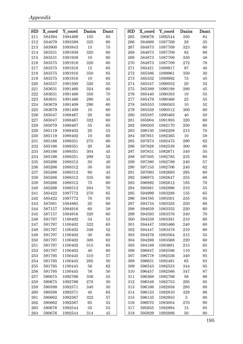
Appendix
195
SID X_coord Y_coord Dazim Damt SID X_coord Y_coord Dazim Damt
211 584394 1094469 105 85 265 590676 1092544 350 84
212 584079 1093388 325 60 266 584869 1087769 28 35
213 583900 1093843 15 75 267 584873 1087709 323 60
214 583531 1091939 320 60 268 584873 1087709 82 88
215 583531 1091939 10 60 269 584873 1087709 330 48
216 583575 1091916 320 60 270 584873 1087709 272 78
217 583575 1091916 15 65 271 585421 1089917 87 40
218 583575 1091916 350 85 272 585386 1089961 350 30
219 583575 1091916 10 65 273 585332 1089992 75 45
220 583537 1091500 320 55 274 585347 1090052 20 52
221 583631 1091466 324 60 275 585389 1090198 280 45
222 583631 1091466 350 70 276 585440 1090383 10 55
223 583631 1091466 290 45 277 585479 1090466 25 55
224 583679 1091409 290 60 278 585553 1090503 10 52
225 583679 1091409 10 60 279 585559 1090512 300 60
226 585047 1088467 20 60 280 585587 1090465 40 50
227 585047 1088467 322 60 281 585904 1091883 320 60
228 585079 1088467 55 65 282 598205 1082170 250 60
229 585119 1088402 20 55 283 598150 1082208 215 70
230 585119 1088402 10 60 284 597951 1082365 10 58
231 585166 1088351 275 60 285 597973 1082475 290 62
232 585166 1088351 20 56 286 597928 1082538 300 60
233 585166 1088351 304 45 287 597831 1082671 340 55
234 585166 1088351 298 52 288 597505 1082785 235 60
235 585266 1088312 50 40 289 597380 1082789 240 57
236 585266 1088312 30 50 290 597155 1082706 240 62
237 585266 1088312 60 45 291 597093 1082693 295 60
238 585266 1088312 335 60 292 596975 1082647 255 68
239 585266 1088312 75 60 293 596892 1082612 185 70
240 585266 1088312 284 70 294 595881 1082996 210 55
241 585422 1087772 270 65 295 594999 1083288 135 65
242 585422 1087772 70 85 296 594785 1083301 235 85
243 587081 1084865 20 60 297 594734 1083325 250 68
244 587157 1084916 60 58 298 594659 1083352 220 60
245 587157 1084916 320 60 299 594593 1083376 240 70
246 591797 1100402 34 53 300 594559 1083381 210 60
247 591797 1100402 322 65 301 594447 1083466 240 60
248 591797 1100402 346 52 302 594447 1083478 210 60
249 591797 1100402 30 60 303 594276 1083564 215 55
250 591797 1100402 300 62 304 594269 1083568 220 60
251 591797 1100402 315 65 305 594188 1083681 215 65
252 591797 1100402 40 60 306 596847 1082586 110 83
253 591795 1100445 310 57 307 596778 1082556 340 85
254 591795 1100445 285 50 308 596631 1082491 65 83
255 591795 1100445 56 62 309 596543 1082533 344 85
256 591795 1100445 76 50 310 596457 1082566 347 87
257 590675 1092766 336 55 311 596368 1082706 58 86
258 590675 1092766 278 50 312 596349 1082753 295 85
259 590598 1092571 340 50 313 596166 1082858 293 88
260 590598 1092571 40 65 314 596153 1082910 328 86
261 590662 1092567 322 57 315 596135 1082953 5 80
262 590662 1092567 65 55 316 596070 1083004 270 90
263 590676 1092544 35 53 317 595955 1082994 15 85
264 590676 1092544 314 45 318 595929 1082986 50 80

Appendix
196
SID X_coord Y_coord Dazim Damt
319 595712 1083025 306 70
320 595638 1083002 345 65
321 595579 1083023 80 56
322 595518 1083084 290 86
323 595472 1083118 340 80
324 595338 1083204 64 75
325 595271 1083219 275 85
326 595140 1083212 10 50
327 594074 1083725 60 65
328 594010 1083756 22 75
329 594002 1083860 20 80
330 593985 1083880 306 85
331 593944 1083910 70 88
332 593876 1084022 310 85
333 593731 1084106 320 75
334 593676 1084157 60 60
335 593558 1084241 46 70
336 593552 1084281 290 60
337 593497 1084377 355 65
338 593424 1084464 272 86
339 593364 1084439 335 85
340 593249 1084478 15 84
341 593190 1084545 350 83
342 593049 1084535 340 85
343 592972 1084442 95 25
344 592806 1084554 230 85
345 592790 1084599 250 85
346 592652 1084629 300 80
347 592547 1084681 210 10
348 592503 1084725 180 80
349 592422 1084829 210 75
350 592448 1084926 170 80
351 592433 1084962 290 10
352 592223 1085013 50 85
353 592099 1085190 205 82
354 592055 1085270 215 88
355 591971 1085393 20 55
356 591844 1085402 330 85
357 591727 1085412 310 88
358 591657 1085478 210 15
359 591619 1085640 180 80
360 591524 1085754 250 68

Curriculum Vitae
197
Curriculum Vitae
Personal details
Name Tesfay Kiros Mebrahtu
Address Institute of Geology, Mineralogy and Geophysics
Universitätsstraße 150
44801 Bochum, Germany
Email: [email protected]/[email protected]
Education
Sep. 2009 – Jul. 2011 Master of Science (MSc) in Geological Engineering
Mekelle University, Ethiopia
Sep. 2004 – Jul. 2008 Bachelor of Science (BSc) in Applied Geology
Mekelle University, Ethiopia
Professional experience
Oct. 2015 – Present Research Assistant (PhD candidate) in Applied Geology
Department (Hydrogeology working group) at the
Institute of Geology, Mineralogy and Geophysics
Ruhr-Universität Bochum, Germany
Jul. 2011 – May 2015 Academic staff at Department of Geology
Addis Ababa Science and Technology University
Addis Ababa, Ethiopia
Oct. 2008 – Aug. 2009 Junior Hydrogeologist
Relief Society of Tigray (REST), Mekelle, Ethiopia

Publications
198
Publications
Mebrahtu, T.K., Hussien, B., Banning, A., Wohnlich, S. (2020a). Predisposing and
triggering factors of large-scale landslides in Debre Sina area, central Ethiopian
highlands. Bulletin of Engineering Geology and the Environment.
Mebrahtu, T.K., Alber, M., Wohnlich, S. (2020b). Tectonic conditioning revealed by
seismic refraction facilitates deep-seated landslides in the western escarpment of
the Main Ethiopian Rift. Geomorphology. 370. 107382.
Mebrahtu, T.K., Banning, A., Hagos, E., Wohnlich, S. (2021). The effect of
hydrogeological and hydrochemical dynamics on landslide triggering in the central
highlands of Ethiopia. Hydrogeology Journal.
Mebrahtu, T.K., Heinze, H., Wohnlich, S., Alber M. (submitted). Slope stability
analysis of deep-seated landslides using Limit Equilibrium and Finite Element
methods under static and seismic load in Debre Sina area, Ethiopia.
Scientific Meetings
Mebrahtu, T.M., Wohnlich, S., Alber, M., Hussien B., Banning, A. (2019).
Integrated approach to unravel mechanics of slope failure inducing landslides in
Debre Sina area, central highlands of Ethiopia. 2018 WMESS, Prague, Czech
Republic (Presentation).
Kiros, T., Wohnlich, S., Alber, M., Hussien, B. (2018). Oblique divergence
activating large-scale rainfall induced landslides: Evidence from Tarma Ber,
Northwestern Plateau of Ethiopia. – AGU Fall Meeting 2018, Washington, D.C,
U.S.A (Poster).
Mebrahtu, T., Wohnlich, S. (2018). The effect of groundwater and rainfall on
landslide triggering in the central Highlands of Ethiopia: the case of Debre Sina
Area. – 26. Tagung der Fachsektion Hydrogeologie (FH-DGGV), Bochum, Germany
(Poster).

Publications
199
Kiros, T., Wohnlich, S., Hussien, B. (2017). Large-scale landslide triggering
mechanisms in Debre Sina area, Central Ethiopian Highlands at the western Afar
rift margin. – AGU Fall Meeting 2017, New Orleans, U.S.A (Poster).