FACULTY OF SCIENCE Institute of Engineering and Technology Department of Civil and Building...
66
FACULTY OF SCIENCE Institute of Engineering and Technology Department of Civil and Building Engineering YEAR II, SEMESTER II NOTES DCE 225–CONCRETE TECHNOLOGY By Solomon Ahimbisibwe February 2013
-
Upload
independent -
Category
Documents
-
view
3 -
download
0
Transcript of FACULTY OF SCIENCE Institute of Engineering and Technology Department of Civil and Building...

FACULTY OF SCIENCE
Institute of Engineering and Technology Department of Civil and Building Engineering
YEAR II, SEMESTER II
NOTES
DCE 225–CONCRETE
TECHNOLOGY
By
Solomon Ahimbisibwe
February 2013

Kabale University
©DCE 225–Concrete Technology, Lecture Notes. ©SA- 2013.Email: [email protected]. Mobile No: (256) 704 204556
i Table of Contents
i
Course Structure
Second Year; Semester II
Core Course: Yes
Lecture Hours [L]: 45 Contact Hours [CH]: 60
Practical Hours [P]: 30 Credit Units [CU]: 4
Class Hours Full-Time Week-end
Wednesday 1000 -1200 hrs
Thursday 0900 – 1100 hrs
Saturday 1400 – 1600hrs & 1700-1900 hrs
Course Assessment
Coursework 40% (Practical 10, Assignments 5, Test 25)
Final Exam 60%
Normal Progress
Grade Point (GP) 2.0 [50%]
Course Outline
Concrete as a Building Material
Aggregates and their Grading
Cement
Types of Portland Cement
Properties of Fresh and Hardened Concrete
Formwork
Steel Reinforcement
Concrete Mix Design
Kabale University ©DCE 225–Concrete Technology, Lecture Notes. ©SA- 2013.Email: [email protected]. Mobile No: (256) 704 204556
ii
Table of Contents 1.0 Introduction .......................................................................................................................... 1
1.1 General ................................................................................................................................. 1
1.2 Definition and Properties of Concrete ................................................................................. 1
1.3 Advantages of concrete as a structural material .................................................................. 2
1.4 Disadvantages of Concrete as a structural material ............................................................. 3
1.5 References ............................................................................................................................ 3
2.0 Aggregates ........................................................................................................................... 4
2.1 General ................................................................................................................................. 4
2.2 Classification of Aggregates ................................................................................................ 4
2.2.1Classification by Shape ...................................................................................................... 4
2.2.2 Classification by Type ...................................................................................................... 5
Igneous Rocks ............................................................................................................................ 5
Sedimentary Rocks .................................................................................................................... 6
Metamorphic Rocks ................................................................................................................... 6
2.2.3 Classification by Size ........................................................................................................ 6
2.3 References ............................................................................................................................ 8
3.0 Cement ............................................................................................................................... 10
3.1 Types of Cement ................................................................................................................ 10
3.1.1 Ordinary Portland Cement .............................................................................................. 10
3.2 Manufacture of Ordinary Portland cement ........................................................................ 10
3.2.1 Wet process ..................................................................................................................... 11
3.2.2 Dry process ..................................................................................................................... 12
3.3 Hydration of Cement.......................................................................................................... 13
3.4 Setting ................................................................................................................................ 13
3.5 Water .................................................................................................................................. 14
3.5.1 Quality of Mixing Water ................................................................................................. 14
3.6 References .......................................................................................................................... 14
3.0 Concrete ............................................................................................................................. 15
3.1 Definition of Concrete ....................................................................................................... 15
3.2 Properties of Fresh Concrete .............................................................................................. 15
3.3 Properties of Hardened Concrete ....................................................................................... 16
Kabale University ©DCE 225–Concrete Technology, Lecture Notes. ©SA- 2013.Email: [email protected]. Mobile No: (256) 704 204556
iii
3.4 Materials for Concrete ....................................................................................................... 18
3.5 Storing Materials for Concrete........................................................................................... 19
3.6 Estimating Quantities of Materials for Concrete Work ..................................................... 20
3.7 Mixing Concrete ................................................................................................................ 22
3.71 Hand mixing..................................................................................................................... 22
3.72 Mechanical mixing........................................................................................................... 23
3.8 Transporting Concrete ....................................................................................................... 24
3.81 Methods of transporting concrete .................................................................................... 24
3.82 Maintaining the quality of concrete during transportation .............................................. 25
3.9 Placing Concrete ................................................................................................................ 25
3.9.1 Compacting Concrete...................................................................................................... 26
3.9.2 Protecting Concrete ......................................................................................................... 28
3.9.3 Curing Concrete .............................................................................................................. 28
3.10 References ........................................................................................................................ 29
4.0 Formwork ........................................................................................................................... 30
4.1 Materials for Formwork ..................................................................................................... 30
4.2 Form treatment, care and removal ..................................................................................... 32
4.3 Positioning the formwork .................................................................................................. 32
4.4 Timbering to excavations ................................................................................................... 34
4.5 Sheet piles .......................................................................................................................... 34
4.6 Cleaning and Storing Formwork ........................................................................................ 35
4.7 References .......................................................................................................................... 35
5.0 Reinforcement .................................................................................................................... 36
5.1 Storage of Reinforcement .................................................................................................. 36
5.2 Fixing Reinforcement in Place........................................................................................... 36
5.3 Uses of Steel Reinforcement .............................................................................................. 36
5.4 Types of Steel Reinforcement ............................................................................................ 37
5.5 Nominal and actual bar sizes ............................................................................................. 37
5.6 Drawings and Schedules .................................................................................................... 38
5.7 Bar call-ups on reinforcement drawings ............................................................................ 39
5.8 Shape codes ........................................................................................................................ 42
5.9 Bending schedules for bar reinforcement .......................................................................... 44
5.10 References ........................................................................................................................ 48

Kabale University ©DCE 225–Concrete Technology, Lecture Notes. ©SA- 2013.Email: [email protected]. Mobile No: (256) 704 204556
iv
6.0 Concrete Mix Design ......................................................................................................... 49
6.1 Advantages of mix design .................................................................................................. 49
6.2 Method of Concrete Mix Design ....................................................................................... 49
6.3 Material Properties ............................................................................................................. 50
6.4 References .......................................................................................................................... 54

Kabale University
©DCE 225–Concrete Technology, Lecture Notes. ©SA- 2013.Email: [email protected]. Mobile No: (256) 704 204556
v
v List of Tables
List of Tables
Table 1: Particle Shape Classification according to BS 812 part 1: 1975 ................................. 5
Table 2: Example of Volume Batching ................................................................................... 21
Table 3: Approximate Water Demand for Different Workability ........................................... 53

Kabale University
©DCE 225–Concrete Technology, Lecture Notes. ©SA- 2013.Email: [email protected]. Mobile No: (256) 704 204556
vi
vi List of Figures
List of figures
Figure 1: Normal Frequency Distribution Curve for Characteristic Strength of Concrete ........ 1
Figure 2: Particle Size Distribution Chart for Grading .............................................................. 9
Figure 3: Wet Process of Cement Manufacture ....................................................................... 12
Figure 4: Dry Process of Cement Manufacture ....................................................................... 12
Figure 5: Good practice of Cement Storage ............................................................................ 20
Figure 6: Dimensions of a Batch Box ...................................................................................... 21
Figure 7: Procedure for Hand Mixing ...................................................................................... 22
Figure 8: Positions of Mixer Machine during Work ................................................................ 23
Figure 9: Placement of Concrete .............................................................................................. 26
Figure 10: Hand Compaction ................................................................................................... 27
Figure 11: Recommended Height for Mechanical Compaction .............................................. 28
Figure 12: Formwork to Columns............................................................................................ 31
Figure 13: Formwork to Footings ............................................................................................ 33
Figure 14: Formwork to Beams ............................................................................................... 34
Figure 15: Timbering for Excavations ..................................................................................... 34
Figure 16: Sheet Piling............................................................................................................. 35
Figure 17: Characteristic Strength of Steel .............................................................................. 37
Figure 18: Bar Notations and Grades....................................................................................... 38
Figure 19: Abbreviations for Bar Location and Arrangement ................................................. 39
Figure 20: Bar Call-ups ............................................................................................................ 40
Figure 21: Bar Schedules and Arrangement ............................................................................ 41
Figure 22: Preferred Standard Shapes for Reinforcement ....................................................... 42
Figure 23: Other Preferred Standard Shapes I ......................................................................... 43
Figure 24: Other Preferred Standard Shapes II ........................................................................ 44
Figure 25: Presentation of Footing Reinforcement .................................................................. 45
Figure 26: Simple Bar Bending Schedule in Relation to Figure 25 ........................................ 46
Figure 27: Footing Details for Practice Example .................................................................... 47
Figure 28: Free Water/Cement Ratio and Concrete Strength at 28 Days ................................ 53
Figure 29: Recommended proportions of fine aggregate passing a 600μ sieve ...................... 55
Figure 30: Recommended proportions of fine aggregate passing a 600μ sieve I .................... 56
Figure 31: Recommended proportions of fine aggregate passing a 600μ sieve II ................... 57
Figure 32: Wet density of fully compacted concrete and relative densities of aggregate ...... 58

Kabale University
©DCE 225–Concrete Technology, Lecture Notes. ©SA- 2013.Email: [email protected]. Mobile No: (256) 704 204556
vii
vii Symbols and Abbreviations
Symbols and Abbreviations
C30 Concrete Grade 30
BS British Standard
EN European Standard
CE Civil Engineering
W/C Water Cement Ratio
SANS South African National Standard
R Reinforcement of Grade 250
T Reinforcement of Grade 460
Kabale University
©DCE 225–Concrete Technology, Lecture Notes. ©SA- 2013.Email: [email protected]. Mobile No: (256) 704 204556
1
1 Introduction
Chapter One 1.0 Introduction
1.1 General
Diploma holders in Civil Engineering are supposed to supervise concreting operations
involving proportioning, mixing, transporting, placing, compacting, finishing and curing of
concrete. To perform above functions, it is essential to impart knowledge and skills regarding
ingredients of concrete and their properties; properties of concrete in plastic and hardened
state, water cement ratio and workability; proportioning for ordinary concrete; concreting
operations and joints in concrete.
1.2 Definition and Properties of Concrete
Concrete is a mixture of water, cement, sand, gravel, crushed rocks, or other "aggregates". As
can be appreciated, it is difficult to produce a homogeneous material from these components.
Furthermore, its strength and other properties may vary considerably due to operations such
as transportation, compaction and curing. In reinforced concrete two materials are combined;
concrete as a formable material with a high compressive strength and on the other side steel,
as a material with an enormous high tensile strength. Concrete is strong in compression but
weak in tension. Because of this it is normal to provide steel reinforcement in those areas
where tensile stresses in the concrete are most likely to develop. Consequently, it is the
tensile strength of the reinforcement that resists the tensile stresses.
The designer of a concrete construction has to place the reinforcement steel in such a way,
that it can take up the tensile forces, while the concrete takes up the compressing forces.
Therefore we have to know in which part of a construction pressure or tensile forces occur.
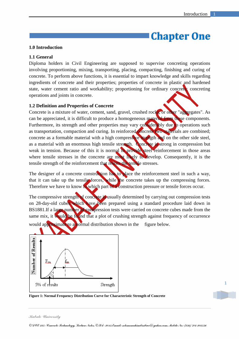
The compressive strength of concrete is usually determined by carrying out compression tests
on 28-day-old cubes which have been prepared using a standard procedure laid down in
BS1881.If a large number of compression tests were carried on concrete cubes made from the
same mix, it would be found that a plot of crushing strength against frequency of occurrence
would approximate to a normal distribution shown in the figure below.
Figure 1: Normal Frequency Distribution Curve for Characteristic Strength of Concrete

Kabale University ©DCE 225–Concrete Technology, Lecture Notes. ©SA- 2013.Email: [email protected]. Mobile No: (256) 704 204556
2
For design purposes it is necessary to assume a unique value for the strength of the mix.
However, choosing too high a value will result in a high probability that most of the structure
will be constructed with concrete having strength below this value. Conversely, too low a
value will result in inefficient use of the material. As a compromise between economy and
safety, BS 8110 refers to the characteristic strength (fcu) which is defined as the value below
which not more than 5% of the test results fall.
The characteristic and mean strength (fm) of a sample are related by the expression
Where is the standard deviation. Thus assuming that the mean strength is 35 N/mm2
and
standard deviation is 3N/mm2, the characteristic strength of the mix is: 35 – 1.64 x 3 = 30
N/mm2.
Concrete of a given strength can be identified by its „grade‟. For example a grade 30 concrete
(C30) has a characteristic strength of 30 N/mm2. For reinforced concrete made with normal
aggregates, BS8110 recommends that the lowest grade of concrete should be C25 although,
in practice, a C30 mix is invariably necessary because of durability considerations.
1.3 Advantages of concrete as a structural material
Reinforced concrete may be the most important material available for construction. It is used
in one form or another in almost all structures, great or small - buildings, bridges, tunnels,
pavement, walls, slabs, beams, water tanks, drainages and roads. The reason, why concrete
and reinforced concrete is used that much, can easily be explained by showing up some of its
advantages:
It has considerable compressive strength as compared to most other materials.
Reinforced concrete has great resistance to the actions of fire and water and, in fact,
is the best structural material available for situation where water is present. During
fires of an average intensity, members with a satisfactory cover of concrete over the
reinforcement bars suffer only surface damage without failure.
Reinforced concrete is very rigid.
It is a low-maintenance material
As compared with other materials, it has a very long service life. Under proper
conditions, reinforced concrete structures can be used indefinitely without reduction
of their load-carrying abilities. This can be explained by the fact that the strength of
the concrete does not decrease with time by actually increase over a very long period,
measured in years, due to the lengthy process of the solidification of the cement paste.
It is usually the only economical material available for footings, basement walls,
piers, and similar applications.
A special feature of concrete is its ability to be cast into an extraordinary variety of
shapes from simple slabs, beams, and columns to great arches and shells.
In most areas, concrete takes advantage of inexpensive local materials (sand, gravel
and water) and requires relatively small amounts of cement and reinforcing steel.
With its‟ PH-value of about 12.5 it protects the reinforcement steel from rusting.
64.1 mcu ff

Kabale University ©DCE 225–Concrete Technology, Lecture Notes. ©SA- 2013.Email: [email protected]. Mobile No: (256) 704 204556
3
1.4 Disadvantages of Concrete as a structural material
To use concrete successfully the designer must be completely familiar with its weak points as
well as with its strong ones. Among its disadvantages are the following:
Concrete has a very low tensile strength, requires the use of tensile reinforcement.
Forms are required to hold the concrete in place until it hardens sufficiently. In
addition, falsework or shoring may be necessary to keep the forms in place for roofs,
walls, and similar structures until the concrete members gain sufficient strength to
support themselves. Formwork is very expensive.
The low strength per unit of weight of concrete leads to heavy members. This
becomes an increasingly important for long-span structures where concrete's large
dead weight has a great effect on bending moments.
Similarly, the low strength per unit of volume of concrete means members will be
relatively large, an important consideration for tall buildings and long-span structures.
The placing and curing of concrete is not as carefully controlled, as is the production
of other materials such as structural steel and laminated wood.
Another problem is the problem of shrinkage which will be mentioned later.
1.5 References
1. BS 8110 (1997). The structural use of concrete, Part 1 Code of practice for design and
construction. British Standards Institution.
2. BS 6399 (1984). Design loading for buildings, Part 1 Code of practice for dead and
imposed loads. British Standards Institution.
3. BS 5950 (1990). Structural use of steel work in buildings, Part 1 Code of practice for
design in simple continuous construction: hot rolled sections. British Standards
Institution.
4. W.H. Mosley, J.H. Bungey & R.Hulse. Reinforced Concrete Design, fifth edition.
Macmillan Press Ltd London, 1999
5. S.P.Timoshenko & D.H. Young. Theory of structures
6. P.N. Khanna. Civil Engineering Hand book
7. Roy Chudley & Roger Greeno. Advanced Construction Technology
8. J.B. Higgins & B.R Rogers. Designed and Detailed (BS 8110 1985, second edition,
Cement and concrete Association.

Kabale University
©DCE 225–Concrete Technology, Lecture Notes. ©SA- 2013.Email: [email protected]. Mobile No: (256) 704 204556
4
4 Aggregates
Chapter Two 2.0 Aggregates
2.1 General
Aggregates are inert materials mixed with cement in the preparation of mortar or concrete.
However, the aggregates may not completely be inert as in some cases their chemical
compositions may affect (to a varying degree) the properties or concrete in both its plastic
and hardened states. Aggregates serve the following purposes in concrete:
i. To improves both the volume stability and durability of the resulting concrete.
ii. To reduce the cost of concrete. Most aggregates are natural materials. Which require
only extraction, washing and grading prior to transport to site.
iii. Correctly graded aggregates produce workable yet cohesive concrete.
iv. To reduce the heat of hydration of concrete since they are normally chemically inert
and act as a heat sink for hydrating of cement.
v. To reduce the shrinkage of concrete since most aggregates are not affected by water
and to restrain shrinkage of the hydration cement.
Additionally, aggregate may serve the following purposes:
vi. To control the surface hardness. Most aggregates have a better abrasion resistance
than hydrated cement but where heavy abrasion is anticipated, hard, high strength
aggregates such as granite or carborundum can be incorporated.
vii. For colour or light reflecting properties. Aggregates can be exposed for their visual
properties.
viii. To control density of the concrete. Some lightweight aggregates have densities below
500 kg/m3 while others have solid densities over 7000 Kg/m3. In general natural
aggregates having solid densities in the region of 2600 kg/m3 are most widely used.
The former types finding application where high density concretes are required.
ix. To control fire. Lightweight concretes are best in fire control because they transmit
heat more slowly than dense concrete.
2.2 Classification of Aggregates
2.2.1Classification by Shape
The external characteristics of aggregates in particular the particle shape and surface texture
are of great importance. The shape is easily defined using certain geometric characteristics.
Shapes vary from 'rounded' (implying water-worn material) to irregular (material with clearly
defined edges produced by crushing). Particles in between would be classed as irregular that
is having rounded edges. In normal concrete, angular material tends to produce concrete of
lower workability but higher strength for a given water / cement ratio. In high-strength
concrete, the reverse is true - some angular aggregates may produce higher workability than
rounded aggregates. Other shapes are 'flaky' and 'elongated' but the non-isotropic nature and
relatively high specific surface of these detracts from their value as aggregates for concrete.

Kabale University ©DCE 225–Concrete Technology, Lecture Notes. ©SA- 2013.Email: [email protected]. Mobile No: (256) 704 204556
5
Roundness measures the relative sharpness or angularity of the edges and corners of a
particle.
Roundness is controlled largely by the strength and abrasion resistance of the parent rock and
by the amount of wear to which the particles have been subjected. In the case of crushed
rock, roundness depends on the nature of the parent material and on the type of crusher and
its reduction ratio i.e. the ration of the size of the material fed into the crusher to the size of
the finished product.
Table 1: Particle Shape Classification according to BS 812 part 1: 1975
Classification Description Examples
Rounded Fully water worn or completely shaped
by attrition
River or seashore gravel,
desert seashore and wind-
blown sand
Irregular Naturally irregular or partly shaped by
attrition and having rounded edges
Other gravels, land or dug
flint
Flaky Material of which the thickness is small
relative to the other two dimensions
Laminated rock
Angular Possessing well defined edges formed at
intersections of roughly planar faces
Crushed rock of all types;
talus; crushed slag
Elongated Material usually angular, in which the
length is considerably larger than the
other two dimensions
-
Flaky and
elongated
Material having the length considerably
larger than the width and the width
considerably larger than the thickness
-
2.2.2 Classification by Type
Geology
Great majority of aggregate used in concrete are obtained from natural sources either from
rocks crushed to desired size or gravel screened and crushed. Thus, the properties of the
parent rock will affect the properties of the aggregate. Rock was formed in three ways:
Igneous, Sedimentary and Metamorphic.
Igneous Rocks
Molten rock is called magma and all rocks derived from the cooling of magma are termed
Igneous Rocks. They include granite, basalt and flint group of aggregates.

Kabale University ©DCE 225–Concrete Technology, Lecture Notes. ©SA- 2013.Email: [email protected]. Mobile No: (256) 704 204556
6
Sedimentary Rocks
Materials transported by water, ice, wind or gravity collect in low-lying areas. In time, the
transported materials consolidate into Sedimentary rock. The sedimentary rocks generally
contain the less readily weathered material of the parent rock. They include limestone and
sandstone.
Concrete made with limestone aggregate has
i. Low coefficient of thermal expansion
ii. Excellent fire resistance
iii. Less abrasion resistance compared to others
Generally, for aggregates of sedimentary origin, abrasion resistance is not as good as other
aggregate types. Some sandstones are of high strength while others are less enduring and
exhibit significant moisture movement.
Metamorphic Rocks
Metamorphic rocks are those in which new minerals or new structures or both have been
formed in pre-existing rock masses, whether of igneous or sedimentary origin. The changes
were induced by increased temperature or pressure, often together, and either with or without
accompanying mineral solutions. An example of such an aggregate is marble. These are
generally not good for concreting works.
2.2.3 Classification by Size
In a typical medium strength concrete mix, aggregates may be classified as fine or coarse,
natural or artificial, dense or lightweight according to the requirements of the users. The
aggregate is classified as fine or coarse depending on the largest size of particle present in
substantial amount. For general building purposes, a fine aggregate is one which will mainly
pass a 5 mm square mesh sieve, and a coarse aggregate is one, which will mainly be retained
on that sieve. An aggregate, which has substantial amounts of both fine and coarse aggregate,
is termed as an all-in aggregate. Fine aggregates are used with appropriate binder to produce
materials for rendering, plastering, flooring and road surfacing. They are also used with
cement binders for jointing material for pipes, bedding for tiles and mortars for brickwork
and block work. For concrete, fine aggregates are normally used together with cement and
coarse aggregates or alternatively, all-in aggregates can be used.
The classification of aggregates gives little chance of ensuring its suitability for particular
purpose e.g sand suitable for concreting works may be too coarse for plastering. In practice
we are concerned not only with the maximum particle size of an aggregate but with the
amount of the various sizes present in the grading. Grading requirements depend on the
proposed use of the aggregate.
Grading
The term is used to describe the relative proportions of various particle sizes between the
nominal maximum aggregate size and the smallest material present and which passes a 150-
micrron sieve. The object of grading aggregates is to produce concrete with satisfactory
plastic properties (i.e. workability, cohesion, and resistance to bleeding) as well as
satisfactory hardened properties (strength, durability and surface finish) using as little cement
as possible.
The need for grading arises from the requirements that:
i. Aggregates fill as much as possible of the total space.

Kabale University ©DCE 225–Concrete Technology, Lecture Notes. ©SA- 2013.Email: [email protected]. Mobile No: (256) 704 204556
7
ii. Aggregates and cement, being much denser than water tend to settle while the
mixing water rises.
A well-graded aggregate will ensure that:
i. There are no large volumes of cement paste
ii. Settlement of solids is minimized by particle interference.
iii. Voids between large particles can be filled efficiently with slightly smaller ones the
procedure repeating down to and through the cement grains which are themselves
graded.
Grading is commonly represented graphically as the percentage passing a given BS sieve
size against size. The 'idealized' curve is the Fuller curve in which the percentage passing is
obtained as below:
Of central importance to any aggregate used for concrete of good quality and appearance is
that aggregate grading should be consistent from batch to batch on larger projects, throughout
construction, If aggregates are stored in single stockpile containing all fractions from
maximum size to 150 micron, there is a strong tendency to segregate, larger sizes tending to
fall to the foot of the stockpile sides and this can be avoided if coarse aggregates (graded than
5mm size) are stockpiled separately and then combined with fine aggregates by careful
weight batching at the mixing stage. For fine aggregates, they have a fairly high natural
cohesion, especially if some moisture is present and segregation is therefore not likely.
Quality Control
Quality is considered under the following:
i. Silt; This is defined as material composed of particles passing a 75 micron sieve
Because it has a high specific surface, its presence leads to increased requirements for
water for a given workability; these are also usually of a clayey nature and hence they
decrease the bond between aggregate and cement thus reducing the strength of
concrete.
ii. Organic Impurities - such materials are acidic thus they reduce the alkalinity of
cement which is essentica1 for its hydration thereby setting time and strength are
reduced. Impurities mainly occur in the form of vegetable matter like topsoil or
leaves, normally resulting from poor stockpiling practice.
iii. Other impurities - these include:
Salts - these are present in marine aggregate and will leave a lthin deposit on
each particle unless washed in fresh water. Salts tend to accelerate the early
hydration of cement but most importantly can cause corrosion of embedded
metal. In reinforced and prestressed concrete the total salt content must be
carefully controlled.
Reactive or unsound inclusions - some aggregates contain mineral particles
which react to high alkali levels - a further less serious contamination is a
pyrite particle which on weathering produce unsightly rust remains on the
surface of the affected concrete.
Moisture - Almost all aggregates contain some moisture. It is very important
for batching of aggregates to establish whether this water will contribute to
workability or whether additional water to that based on the mixed design will
be necessary due to absorption by aggregates.
There are four possible moisture states in which an aggregate may exist:
i. Oven-dry - implying that- on heating to 105°C there would be loss of weight - This
state rarely occurs in real life.
ii. Air-dry - there is no free moisture and surface layers of aggregates are dry - This
occurs in upper parts of aggregates stockpiles in dry weather.

Kabale University ©DCE 225–Concrete Technology, Lecture Notes. ©SA- 2013.Email: [email protected]. Mobile No: (256) 704 204556
8
iii. Saturated surface dry - This is an ideal state for an aggregate for concrete since
it requires no alteration to mixing water.
iv. Wet -Qn surface moisture IS present - This is the most common on site.
States (i) and (ii) require extra water to be added at the mixer especially for lightweight
aggregates which are highly absorbent. State (iv), will require a reduction of water at the
mixture equal to the total free moisture present in the batch of the aggregates.
2.3 References
1. Jenkins KJ and Douries W. Gyratory compaction and MMLS3 testing of asphalt
wearing and base courses for Cape Town International Airport taxiway rehabilitation.
Institute for Transport Technology ITT Report 1-2001, University of Stellenbosch,
SouthAfrica (2001) 1-40.
2. Sabita. Interim guidelines for the design and construction of Hot Mix Asphalt in
SouthAfrica. June (2001).
3. Epps AL, Ahmed T, Little DC, Hugo F, Poolman P and Mikhail M. Performance
prediction with the MMLS3 at WesTrack. Paper presented at the 9th International
Conference on Asphalt Pavements, Copenhagen. 2002.
4. Wright DFH and Burgers A. Traffic compaction of bituminous concrete surfacings.
Paper represented at the 4th Conference on Asphalt Pavements for Southern Africa,
Cape Town, South Africa. (1984).

Kabale University
©DCE 225–Concrete Technology, Lecture Notes. ©SA- 2013.Email: [email protected]. Mobile No: (256) 704 204556
9 Aggregates
9
Figure 2: Particle Size Distribution Chart for Grading
Kabale University | ©DCE 225–Concrete Technology, Lecture Notes. ©SA- 2013.Email: [email protected]. Mobile No: (256) 704 204556
10 Cement
10
Chapter Three 3.0 Cement
Cement is a material with adhesive and cohesive properties which make it capable of bonding
mineral fragments into a compact whole. For construction purposes, cement refers to the
bonding material used with stones, sand, bricks, building blocks, etc. The cements of interest
in the making of concrete have the property of setting and hardening under water by virtue of
a chemical reaction with it and are therefore called hydraulic cements. Hydraulic cements
consist mainly of silicates and aluminates of lime and can be classified mainly as natural
cements, Portland cements and high-alumina cements.
3.1 Types of Cement
This discussion is limited to Portland cement types which will be the only class of cement
discussed in this course unit. Different types of Portland cement are obtained by varying the
following; fineness, proportions of the raw materials, temperature of burning and
incorporating in additives.
3.1.1 Ordinary Portland Cement
Ordinary Portland cement is admirably suitable for use in general concrete construction when
there is no exposure to suphates in the soil or ground water. Compared to hydraulic chalk
(limestone) Portland cement hardens much faster and has far higher solidity. These
characteristics are a result of a Chalk-silica acid, which is not contained in the hydraulic chalk
(limestone), the 3-calcium-silica ( 3CaO*SiO2). This 3-calcium-silica can only be produced
at temperatures between 1250 o
C and 2100o
C. The material (as the powerful reaction with
water (H2O) shows), is very unstable. Using only the pure components (74% CaO and 26%
SiO2) leads to a very complicated process of "burning" the cement. Therefore it is necessary,
to add some other components, while the cement is "burned". The most suitable material
turned out to be ferric oxide and argillaceous earth, material that usually anyway shows up
with the silica acid or the chalk (lime). While these components are burned in the rotary kill,
sintering temperature has to be reached. Now the components turn into a mushy mass. After
cooling down again, the material turns into dark, stone-hard pieces, the cement clinker. The
most important factor in this process is to find the perfect mixture of the components. If for
example too much chalk, this chalk will not be turned into 3CaO*SiO2. It will remain in the
final product, covered by the Portland cement. Later, after adding water and the process of
hybridization is almost finished, the chalk will react with the remaining water will increase its
volume, as a consequence the concretes quality will be harmed. In a modern production
process, the single components are measured with a exactness of 0.1 %
3.2 Manufacture of Ordinary Portland cement
Ordinary Portland cement is primarily made of a calcareous material such as limestone or
chalk, and from alumina and silica found as clay or shale. Marl; a mixture of calcareous and
argillaceous material can also be used. The process involves grinding of the raw materials,
mixing them intimately in certain proportions and burning in a large rotary kiln at a

Kabale University ©DCE 225–Concrete Technology, Lecture Notes. ©SA- 2013.Email: [email protected]. Mobile No: (256) 704 204556
11
11 Concrete
temperature of approximately 1400 when the material sinters and partially fuses into balls
known as clinker. The clinker is cooled and ground to a fine powder, with some gypsum
added and the resulting product is the ordinary Portland cement. The mixing or grounding of
the raw materials can be done either in water or in a dry condition hence the names wet and
dry processes.
3.2.1 Wet process
When chalk is produced it is finely broken up and dispersed in a wash mill. This is a circular
pit with revolving radial arms which break up lumps of solid matter. The clay is also broken
up and mixed with water usually in a similar wash mill. The two mixtures are now pumped to
mix in predetermined proportions and pass through a series of screens. The resulting cement
slurry passes into storage tanks.
When limestone is used it has to be blasted, then crushed usually in two progressive smaller
crushers and then fed into a ball mill with the clay dispersed in water. There the breakdown
of the limestone to the fineness of flour is completed and the resultant slurry is pumped into
storage tanks.
In the storage tanks the sedimentation of the suspended solids is prevented by mechanical
stirrers or bubbling by compressed air. Final adjustment in order to achieve the required
chemical composition can be made by blending slurries from different storage tanks
sometimes using an elaborate system of blending tanks. Finally the slurry with the desired
lime content passes into the rotary kiln which is a large refractory lined steel cylinder slowly
rotating about its axis and slightly inclined to the horizontal.
The slurry is fed in at the upper end and the pulverized coal is blown in by an air blast at the
lower end of the kiln where the temperature reaches 1400-1500 . The slurry in its movement
downwards encounters a progressive rise in temperature. At first the water is driven off and
CO2 is liberated; further on the dry material undergoes a series of chemical until finally in the
hottest part of the kiln; some 20-30% of the material becomes a liquid and lime, silica and
alumina recombine.
The mass then fuses into balls (3-25mm) called clinker. The clinker drops into coolers which
are of various types and often provide means for an exchange of heat with the air
subsequently used for the combustion of pulverized ash.
The cooler clinker which is characteristically black, glistening and hard is interground with
gypsum in order to prevent flush setting of the cement. The grinding is done in a ball mill of
several compartments with progressive smaller steel balls.
The cement discharged by the mill is passed through a separator and fine particles are
removed to the storage silo by an air current while the coarse particles are passed through the
mill once again. Once the cement has been satisfactorily ground to the required particle sizes
having 1.1x10¹²
particles per kg it is ready for packing in the familiar paper bags.

Kabale University ©DCE 225–Concrete Technology, Lecture Notes. ©SA- 2013.Email: [email protected]. Mobile No: (256) 704 204556
12
12 Concrete
3.2.2 Dry process
In the dry and semi dry processes, the raw material are crushed and fed in the correct
proportions into a grinding mill, where they are dried and reduced to a fine powder. The dry
powder called raw meal is fed in a blending silo and final adjustment is made in the
proportions of the material required for the manufacture of the cement.
In the semi dry process the blended meal is now sieved and fed into a rotating dish called a
granulator and water weighing about 12% of the meal being fed in at the same time. This
produces hard pellets about 15mm in diameter. The pellets are baked hard in a pre-heating
grate by means of hot gases from the kiln. The pellets then enter the kiln and the subsequent
operations follow in the same way as in the wet process.
Note: Except where the raw materials require use of the wet process, the dry process is
nowadays preferred in order to minimize the energy required for burning.
Figure 3: Wet Process of Cement Manufacture
Figure 4: Dry Process of Cement Manufacture
Kabale University ©DCE 225–Concrete Technology, Lecture Notes. ©SA- 2013.Email: [email protected]. Mobile No: (256) 704 204556
13
13 Concrete
Sample Questions
Question One
a) Differentiate between admixtures and additives (3 marks)
b) Briefly describe the principles of admixtures as regards to changes brought about in
concrete (5 marks)
c) Write short notes on any three admixtures under the following headings
i) Definition (4 marks)
ii) Circumstances under which they are used (4 marks)
iii) Adverse effects (4 marks)
Question Two
a) Write short notes indicating circumstances under which these cement types are used
i) Low heat Portland cement (3 marks)
ii) Special Rapid Hardening Portland cement (3 marks)
iii) White cement (3 marks)
b) Briefly describe the dry process of manufacture of Ordinally Portland cement (11 marks)
3.3 Hydration of Cement
The reactions by which Ordinary Portland cement becomes a bonding agent take place in a
water-cement paste. The silicate and aluminate compounds form products of hydration which
in time produce a firm and hard mass-the hardened cement paste. Direct addition of
molecules of water to cement result in hydration and hydrolysis reactions.
The rate of hydration decreases continuously so that even after some appreciable time, there
is still some hydration reactions taking place.
The hydration of cement compounds is exothermic up to 500 joules per gram of cement being
liberated. For a lager concrete mass hydration can result into a large rise in temperature when
the exterior of the concrete mass is losing some heat hence a high temperature gradient may
result. During subsequent cooling of the interior, serious cracking may arise.
3.4 Setting
This is the term used to describe the stiffening of the cement paste although the definition of
the stiffness of the paste which is considered setting is somewhat arbitrary. Setting refers to a
change from the fluid to a rigid state. It is vital to distinguish setting from hardening. Setting
is caused by the hydration of cement compounds.
The setting process is accompanied by temperature changes in the cement paste: initial set
corresponds to a rapid rise in temperature and final set to the peak temperature.
Kabale University ©DCE 225–Concrete Technology, Lecture Notes. ©SA- 2013.Email: [email protected]. Mobile No: (256) 704 204556
14
14 Concrete
3.5 Water
3.5.1 Quality of Mixing Water
The quality of the water plays an important role on the strength of the resulting concrete.
Impurities in the water may interfere with the setting of the cement, may adversely affect the
strength of the concrete or cause staining of its surface, and may lead to corrosion of the
reinforcement. For these reasons, the suitability of the water for mixing and curing purposes
should be considered. Clear distinction must be made between the effects of mixing water
and the attack on hardened concrete by aggressive waters.
In many specifications, the quality of water is covered by a clause that water should be fit for
drinking. Such water very rarely contains dissolved solids. There is however one situation
when drinking water is unfit for use as mixing water. This is when there is a danger of alkali-
aggregate reaction and the water has high concentration of sodium of potassium.
While the use of potable water is generally safe, water not fit for drinking may often also be
satisfactorily used in concreting. As a rule, water of PH of 6.0-8.0 which does not taste saline
or brackish is suitable for use, but dark colour or smell does not necessarily mean that
deleterious substances are present.
A simple way to determine the suitability of such water is to compare the setting time of
cement and the strength of mortar cubes using the water in question with the corresponding
results obtained using known “good” water or distilled water; there is no appreciable
difference between the behaviour of distilled and ordinary drinking water.
Water containing large quantities of chlorides (e.g sea water) tends to cause persistent
dampness and surface efflorescence. Such water should not be used where the appearance of
concrete is of great importance or where a plaster finish is to be applied. In the case of
reinforced concrete, sea water is believed to increase the risk of corrosion of the
reinforcement.
3.6 References
1. EN 196-1, Methods of testing cement - Part 1: Determination of strength.
2. EN 196-2, Methods of testing cement - Part 2: Chemical analysis of cement.
3. EN 196-3, Methods of testing cement - Part 3: Determination of setting time and
soundness.
4. EN 196-5, Methods of testing cement – Part 5: Pozzolanicity test for Pozzolanic
cements.
5. EN 196-6, Methods of testing cement – Part 6: Determination of fineness.
6. EN 196-7, Methods of testing cement – Part 7: Methods of taking and preparing
samples of cement.
7. EN 196-21 1), Methods of testing cement – Part 21: Determination of the chloride,
carbondioxide and alkali content of cement.
8. The European Standard EN 197-1:2000

Kabale University | ©DCE 225–Concrete Technology, Lecture Notes. ©SA- 2013.Email: [email protected]. Mobile No: (256) 704 204556
15
15 Concrete
Chapter Three 3.0 Concrete
3.1 Definition of Concrete
Concrete is a mixture of cement, water, sand and stone. Other materials (admixtures) are
sometimes used in addition to these to improve certain qualities of concrete.
Good concrete is one of the most useful construction materials because it can be formed to
almost any shape while it is still fresh. When it sets and hardens it becomes strong and
durable and requires very little maintenance.
3.2 Properties of Fresh Concrete
The quality of fresh concrete is good if it is workable, cohesive and does not bleed too much
while it is setting. It is also important to know that concrete can shrink and that heat is given
off while concrete is setting and hardening.
Workability
Concrete is workable if it is easy to place and compact it with available equipment. The
slump test is usually performed to measure the workability of concrete, but other tests exist
for testing special types of concrete.
A low slump measurement means that the concrete is stiff and will have to be vibrated to
compact it properly. If the concrete is sloppy, it will have a higher slump than a stiff mix and
can be compacted by hand. If the workability and slump of a mix is not right, it can usually
be improved if the quantity of sand and stone in the mix is changed.
Cohesiveness
Concrete must be cohesive. This means that it must be sticky enough to prevent the stones
from separating from the mortar when it is being transported, placed and compacted.
Cohesiveness can be improved by the following means:
Making the concrete stiffer
Using smaller stones
Using more of the very fine material in the mix such as dust from the sand or stone.
The cohesiveness of concrete can be judged by tapping the base plate of the slump apparatus
after the slump has been measured. Cohesive concrete will settle without stones falling out of
the lump.
Bleeding and settlement
When fresh concrete has been compacted, some water usually rises to the top surface after a
while. This is called bleeding. It happens because the cement, sand and stone are always
denser than water and settle slightly. Bleeding continues until the concrete sets. Too much

Kabale University ©DCE 225–Concrete Technology, Lecture Notes. ©SA- 2013.Email: [email protected]. Mobile No: (256) 704 204556
16
bleeding can cause ugly patches on concrete surfaces and it may weaken the concrete and
cause cracking. Bleeding can be reduced by:
Making the concrete stiffer
Using more of the very fine material in the mix such as dust from the stone or sand or
extra Cement
Plastic shrinkage
If concrete loses some of its mixing water after it is compacted and before it sets, it shrinks
slightly. This is called plastic shrinkage and it can cause severe cracking.
The loss of water is mostly due to the heat of the sun and hot dry winds blowing over the
concrete. It can also be caused by the use of absorbent formwork or by casting concrete on
dry ground. Ground on which concrete is to be cast should be prewetted and concrete should
be protected from drying out. If cracks are noticed in time they can be closed up by re-
compaction of the concrete.
Setting
When concrete is mixed, the water and cement react with each other. This reaction is very
slow at first, but after an hour or two, the concrete starts to stiffen gradually. The stiffening
continues until the concrete changes into an unworkable solid material. This stage is called
setting. On average, concrete sets after 3 or 4 hours.
Heat of hydration
The heat that is given off as the water and cement in the concrete react is known as the heat
of hydration.
The temperature of the concrete normally continues to rise for many hours after mixing.
If concrete is cast in thin sections, such as drift slabs, the heat is lost so quickly that it may
not be
noticed. If the concrete is insulated or cast in thick sections, the heat cannot escape quickly
and the concrete gets warmer. This rise in temperature can cause cracking of the concrete. It
is advisable to take special precautions if concrete thickness exceeds 1.5 metres.
3.3 Properties of Hardened Concrete
Strength
After concrete has set, it develops strength. Strength development is fastest during the first
day or two.
It gradually slows down until after 28 days, when there is very little gain in strength each day.
Concrete cannot gain strength if it dries out. For normal concrete, using ordinary Portland
cement, the strength at 3 days will be about 50% of the 28-day strength. The strength at 7
days will be about 65% of the 28-day strength.

Kabale University ©DCE 225–Concrete Technology, Lecture Notes. ©SA- 2013.Email: [email protected]. Mobile No: (256) 704 204556
17
To make sure that concrete will continue to gain strength, it must be prevented from drying
out too rapidly and it must be protected against very low temperatures. If this is done, then
after 28 days the concrete will be very near its maximum strength.
The strength of concrete is measured by crushing concrete cubes which have been made and
cured strictly according to a set of rules. The strength of concrete depends on:
The age of the concrete; Concrete gains strength with time, so it follows that the older
the concrete the stronger it is.
The ratio of water and cement in the mix. Water: cement ratio = (mass of water in
mix) / (mass of cement in mix). If the water : cement ratio is too high, the concrete
will not reach the required strength. If the water: cement ratio is too low, the cement is
being wasted.
How well the concrete was compacted
How well the concrete has been cured (curing is keeping the concrete moist after it
has set)
The temperature at which the concrete has hardened
The type of cement used.
Strength is the most important property of hardened concrete.
Durability
Durability of concrete depends mainly on the water: cement ratio of the concrete and how
well it is compacted and cured. High strength concrete is normally used in structures that
have to be durable, e.g. bridges.
Permeability
Permeability describes the ability of the concrete to allow liquid to pass through it. High
strength concrete is used where impermeable waterproof concrete is needed e.g. in water
reservoirs.
Impermeable concrete can be made by:
Using a low enough cement : water ratio for the mix
Compacting properly and not allowing honeycombing in the concrete
Curing thoroughly for a long time.
Drying shrinkage
When concrete is allowed to dry out, say after curing, it shrinks slightly. Although this
shrinkage is small (about 0.3 mm per metre length) it can cause cracking in the concrete.
This problem can be overcome by adopting the following measures:
Design the structure such that the concrete is free to move when it shrinks
Divide the structure into fairly small pieces with joints in between.

Kabale University ©DCE 225–Concrete Technology, Lecture Notes. ©SA- 2013.Email: [email protected]. Mobile No: (256) 704 204556
18
Put reinforcing steel into the concrete; the steel does not stop the shrinkage but
causes many very small cracks instead of a few large ones
The amount of water that is used to make fresh concrete affects the amount of shrinkage that
takes place when the concrete dries out. More water leads to more shrinkage.
Density
If ordinary sand and stone are used, the mass of a cubic metre of concrete is about 2400 kg.
3.4 Materials for Concrete
Portland cement
The main materials used to produce Portland cements are finely ground limestone and clay.
These materials are burnt at high temperatures to form cement clinker. A small quantity of
gypsum is added to the cooled clinker to control the rate of setting. The clinker is then ground
to a fine powder to produce Portland cement.
There are many different types of Portland cement which can be used for different purposes.
Water
The water used in concrete reacts with the cement. It also wets the particles of cement, sand
and stone to lubricate the mix so that the particles can slide and roll over one another when
the concrete is worked.
Water is the cheapest material in concrete, but the quantity of water used can make a big
difference to the quality of the concrete. Potable water should normally be good enough for
making concrete. Impurities in the mixing water can affect the time concrete takes to set, the
strength of the concrete and the colour of the concrete. The impurities can also cause
corrosion (rusting) of the reinforcement steel. Acceptable water for use in concrete shall be:
Clean and free from oil
Free from impurities that may affect the durability of the concrete.
The water: cement ratio should not be more than 0.5 (Normally ranges between 0.4 and 0.5)
Sand
Sand is the fine aggregate used in concrete. Sand, together with water and cement, forms
mortar, this fills the spaces between the stones and coats them thickly enough to keep them
apart. Sand also provides bulk to the concrete to make the concrete cheaper and more stable
(less shrinkage).
The workability, cohesiveness and bleeding of concrete all depend heavily on the quality of
sand. Acceptable sand for use in concrete shall be:
Clean river sand, free from dust, lumps, soft or flaky particles and organic matter.

Kabale University ©DCE 225–Concrete Technology, Lecture Notes. ©SA- 2013.Email: [email protected]. Mobile No: (256) 704 204556
19
Stone
Stone is the coarse aggregate used in concrete. Stone is used to provide bulk in concrete and
to make the concrete more stable (i.e. less shrinkage). Acceptable stone for use in concrete
shall be:
Well graded and free from organic material.
3.5 Storing Materials for Concrete
Storing aggregates (both stone and sand)
During transportation, storage and handling, aggregates must not be contaminated by
impurities such as soil, clay, roots, leaves, fertilizer, sugar, salt, coal, etc. All of these can
affect the quality of concrete.
The rules for good storage are:
Do not place stockpiles under trees as leaves and seeds will contaminate the
aggregates.
Rain water should drain away from stockpiles.
Aggregates should preferably be stockpiled on a concrete floor to prevent mixing
with soil.
If a concrete floor is not used for the stockpile area, then the ground on which the
aggregates are stored must be cleared of grass and roots.
Retaining walls and partitions separating different materials must be high enough and
strong enough to withstand the pressure of the aggregates.
Stockpiles should be at least big enough to contain all the material required for a
day‟s concreting.
Storing cement
Good, dry storage of cement is very important. Concrete made with cement that has been
exposed to moisture in the air or on the ground will be weaker than concrete made with fresh
cement. Lumps in cement are a sign that cement has been exposed to moisture. If this
happens:
As a rough guide on site, if the lumps cannot easily be broken between the fingers, do
not use the cement for any mix apart from concrete class lean for blinding.
For the class lean concrete, you can either sieve out the lumps or increase the amount
of cement in the mix by adding an amount equal to the lumps in the cement bag.
The rules for storing cement are listed below:
The cement must be stored in a weather proof store which must have either a damp
proof floor or a second floor of timber so that the cement bags will be clear of the
ground.
Torn cement bags or bags showing signs of dampness should not be accepted from the
supplier.

Kabale University ©DCE 225–Concrete Technology, Lecture Notes. ©SA- 2013.Email: [email protected]. Mobile No: (256) 704 204556
20
Stack bags close together, but keep a clear space between the sacks and the walls.
Bags must be stacked not more than 12 bags high to avoid compaction of lower bags.
Stack the bags so that the first batch in can be the first out.
The cement store must have a well -ventilated but dry atmosphere.
Figure 5: Good practice of Cement Storage
Storing bagged cement in the open
If it becomes necessary to store sacks of cement in the open, you should;
Make a wooden platform about 300 mm off the ground supported on bricks or timber.
Cover bags with a tarpaulin or plastic sheeting. If more than on sheet is used, overlap
them so that water runs off without wetting the bags.
Weigh down the sheeting at the bottom and on top with reasonable weights that will
not allow the wind to blow the sheeting away.
3.6 Estimating Quantities of Materials for Concrete Work
The method used to estimate the quantity of each material depends on whether the concrete is
being batched by volume or by mass. Batching is the measuring out of the quantities of
materials to be used in the concrete mix. It is important to batch the materials correctly,
because the amounts mixed can affect the workability, strength and cost of concrete used.
Batching by mass is usually more accurate than batching by volume. Batching by mass is
usually recommended for higher strength concrete (class 25 and above). Volume batching is
adequate for most concrete work.
Batching by volume
Cement
Because cement fluffs out and increases in volume when poured out of the cement bag, it is
not advisable to batch cement by loose volume. Whole bags of cement should be used.

Kabale University ©DCE 225–Concrete Technology, Lecture Notes. ©SA- 2013.Email: [email protected]. Mobile No: (256) 704 204556
21
Sand and stone
The following points should be noted when batching sand and stone by volume:
There should be enough gauge boxes to measure all the materials for each batch of
concrete without using any container more than once.
Material in gauge boxes must not be compacted when filling up.
The gauge box must be filled level with the top in order that the volume of material
measured out is equal to the volume of a bag of cement.
Never use a shovel as measure for volume batching
Figure 6: Dimensions of a Batch Box
An example of this volume batching is in the table below;
Table 2: Example of Volume Batching
Concrete
class
Nominal mix
by volume
(maximum
aggregate
size)
Batch with one bag of cement
Number of gauge boxes of
aggregate
sand stone Approximate
yield per
batch (m3)
Cement
in bags
(kgs)
Sand
(m3)
Stone
(m3)
Lean 1:4:8 (40) 4 8 0.30 3.3(166k
g)
0.47 0.94
15 1:3:6 (50) 3 6 0.24 4.3(215k
g)
0.46 0.92
20 1:2:4 (20) 2 4 0.16 6.0(300k
g)
0.42 0.84

Kabale University | ©DCE 225–Concrete Technology, Lecture Notes. ©SA- 2013.Email: [email protected]. Mobile No: (256) 704 204556
22 Concrete
22
3.7 Mixing Concrete
Concrete can be mixed either by hand or by mechanical means. Both methods are discussed
below.
3.71 Hand mixing
The aggregates and cement are thoroughly mixed to uniformly blend with the cement before
water is added. A further thorough mixing operation is required to evenly disperse the water
and make the concrete workable for use.
Concrete should never be mixed on soil. A platform must be built with boards, with metal
sheets or lean concrete. The size of the platform will be such that a continuous mixing
process is possible (e.g. 4m x 6m).The platform should be thoroughly cleaned after use each
day. Prolonged skin contact with cement or concrete should be prevented by protective
clothing such as gloves, overalls and boots.
Figure 7: Procedure for Hand Mixing
The recommended procedure for mixing concrete by hand is outlined below:
Batch coarse and fine aggregate (i.e. stone and sand) by volume such that the total
volume of the batch is not greater than 0.5 m3.
Place the stone and sand on the platform in alternate layers and mix thoroughly by
turning the heap over several times.
The most efficient method of mixing the materials is by two workers facing each
other and working from opposite sides of the heap. Working from the outside to the
centre, they turn the material from the heap onto a new wide, flat heap (conical heaps
encourage segregation). This is repeated at least twice.

Kabale University | ©DCE 225–Concrete Technology, Lecture Notes. ©SA- 2013.Email: [email protected]. Mobile No: (256) 704 204556
23 Concrete
23
Add cement on top of the heap of sand and stone when concrete is about to be
poured.
Note that no water is introduced at this stage. Once again, the heap is thoroughly mixed in the
same way as described in the paragraph above, until the batch is a uniform colour.
Add water by sprinkling the pre-determined quantity gradually on the heap while it is
turned over another three times. As the water : cement ratio exceeds 0.3, water should
be added more carefully in order to get the best workability without exceeding the
water :cement ratio of 0.5. Mixing should be done until the mixture is a uniform
consistency and sufficient workability has been reached.
It must be borne in mind that sand and stone normally have some residual moisture content at
the time of batching. The maximum residual moisture contents shall be 1% for stone and 5%
for sand.
3.72 Mechanical mixing
Mechanical mixing produces a more homogeneous and better mix. A large number of
different types of concrete mixers exist. The most common type is the tilting drum mixer. In
this type of mixer, a drum rotates on an inclined axis when mixing and on a tilted axis for
discharging. Three positions are used:
Charging position (i.e. loading cement, sand gravel)
Mixing position
Discharging position
The capacity of a concrete mixer is usually described by 2 quantities
Figure 8: Positions of Mixer Machine during Work
The first quantity is the charge. This is the total loose volume of sand, stone and cement that
can be loaded into the mixer. The second quantity is the yield. This is the maximum volume
of wet concrete that can be produced , or discharged by the mixer.

Kabale University | ©DCE 225–Concrete Technology, Lecture Notes. ©SA- 2013.Email: [email protected]. Mobile No: (256) 704 204556
24 Concrete
24
The charge and yield of the concrete mixer are usually measured in litres. The description of
the concrete mixer is normally written as, say 750/500, which means that the maximum
charge is 750 litres and the maximum yield is 500 litres. Typical concrete mixer sizes range
from 50/35 to 1500/1000. Efficient mixing can be achieved by following the guidelines
below:
The mixer must be cleaned at the end of the day or when the mixing operation is
interrupted for a long time. This can be done by charging (i.e. loading) the mixer with
a small quantity of stone and water, mixing for a while and then discharging the
cleaning material.
The mixer should be loaded or charged in the following order:
Stone and most of the water
Cement
Sand
The rest of the water
Do not overload the mixer. Overloading leads to poor mixing, spillages and waste of
materials.
Mixing time should be long enough to produce a mix of uniform texture and colour.
Mixture manufacturers provide information on mixing times. A small amount of over mixing
is not serious, but under mixing could be disastrous.
3.8 Transporting Concrete
Concrete must be transported from the place of mixing to the placing position as quickly as
possible (i.e. within 30 minutes) and in such a way that the quality of the concrete is not
affected.
3.81 Methods of transporting concrete
There are many ways of transporting fresh concrete to the point of placing. The choice
depends, among others, on:
the type of job
the size and lay out of the construction site
the rate of production of fresh concrete
Concrete can be transported by using any of the following means:
Ready-mixed concrete trucks
Skips (with hoists or cranes)
Pumps
Dumpers
Wheelbarrows
Headpans
The most common methods of transporting concrete in district roadworks activities are
wheelbarrow and headpans.

Kabale University | ©DCE 225–Concrete Technology, Lecture Notes. ©SA- 2013.Email: [email protected]. Mobile No: (256) 704 204556
25 Concrete
25
3.82 Maintaining the quality of concrete during transportation
The following points require attention and supervision when concrete is transported:
The concrete should not dry out and loose workability due to exposure to dry wind,
hot weather, etc. Concrete should be placed as soon as possible after mixing. If delays
in placing concrete do occur, then concrete that is transported in open headpans or
wheelbarrows should be covered with plastic sheets or tarpaulins to reduce drying out.
Leaking wheelbarrows or headpans should not be used for transporting concrete as
loss of concrete fines may occur.
The wheelbarrows or headpans must be thoroughly cleaned before being used to
transport fresh concrete to avoid contaminating it with other materials such as soil, old
concrete, etc.
Concrete should not become diluted with water. Rain water in wheelbarrows or
headpans should be emptied out before fresh concrete is placed in them. Similarly,
fresh concrete should not be allowed to stand in heavy rain unless it is well covered
with plastic sheets or tarpaulins.
If concrete is transported in wheelbarrows, the haul routes should be kept smooth to
prevent segregation during transportation. If it is not possible to prevent segregation
during transportation, the concrete must be remixed before it is placed. This problem
is usually minimal with headpans as the person carrying the pan acts as an efficient
shock absorber.
The concrete should not be allowed to stiffen or set during transportation. Higher
concrete classes are more susceptible to stiffening than the lower grades, particularly
in hot weather if the transportation time is too long.
3.9 Placing Concrete
The most common problems that occur when concrete is placed in position are listed below:
Rubbish such as saw dust, wood shavings, wire, etc. is left in the formwork and
contaminates the concrete. The problem can be eliminated by inspecting and cleaning
the formwork just before the concrete is placed.
Cold joints can occur between layers of concrete if there is too long a delay in
placing successive layers.
Segregation takes place and causes honeycombing in the concrete. Segregation that is
caused when concrete is placed can be prevented by applying the following rules:
The concrete should always be placed as closely as possible to its final
position. It should be placed into corners and into working faces and not away
from them.
Do not move concrete sideways after placing, especially with a poker
vibrator.
In deep pours, such as abutments and piers, do not allow the concrete to fall
onto the reinforcement because some of the mortar will remain on the bars
while the stone falls to the bottom.
The best way of preventing segregation in deep pours is to increase the amount of mortar in

Kabale University | ©DCE 225–Concrete Technology, Lecture Notes. ©SA- 2013.Email: [email protected]. Mobile No: (256) 704 204556
26 Concrete
26
the first batch of concrete that is poured. The easiest way to do this is to leave out half of the
stone and adjust the water : cement ratio accordingly to give the right slump.
Another way is to use a wooden or steel funnel to pour the concrete. This will not only
prevent segregation but may also prevent pouring of concrete outside the formwork. The
mouth of the funnel should be approximately 50 cm above the bottom of the form to start
with and must be lifted at the same rate as the rising concrete.
When concrete is being placed in sloping lifts, such as drift and/or causeway approach slabs,
placing should start at the bottom and work upwards in horizontal layers.
When concrete is placed around horizontal void formers, it should be placed from one
side until it can be seen from the other side to have filled the space under the void
former.
Concrete must be placed in layers of maximum depth of 300 mm for hand compaction and
600 mm for mechanical compaction.
Figure 9: Placement of Concrete
3.9.1 Compacting Concrete
Concrete must be properly compacted to remove all the air voids trapped in it. There are
several methods of compacting concrete but the most common in roadworks are:
Hand compaction (hand ramming) and
Mechanical vibration (internal vibration using a poker vibrator)
Hand compaction
Hand compaction is normally used for concrete in wall foundations, unreinforced slabs and
blinding layers. Concrete that will be hand compacted should have a slump of about 75 mm
to 125 mm. Spades and suitable pieces of timber are normally used to rod and compact the
concrete. Gumbooted feet work very well for compacting concrete in footings.

Kabale University | ©DCE 225–Concrete Technology, Lecture Notes. ©SA- 2013.Email: [email protected]. Mobile No: (256) 704 204556
27 Concrete
27
Figure 10: Hand Compaction
For ground slabs, e.g. aprons, a heavy screed board is also used to compact the concrete. The
board is used first in a chopping motion and, when mortar forms on the surface of the
concrete, it is used in a sawing motion to screed the concrete to the correct level.
Small pre-cast items such as paving slabs can be compacted by jolting the mould on a
concrete floor.
Mechanical vibration
Concrete that will be vibrated should have a slump of about 35 mm to 75 mm. Intenal
vibration using a poker vibrator is the most common method of compacting concrete. To
ensure good compaction, the following points are important:
Concrete should be placed in layers not deeper than 300 mm and each layer should be
vibrated before the next layer is placed. The poker should penetrate the layer below
the one being compacted.
The poker should be pushed vertically into the concrete as quickly as possible. The
poker should be withdrawn slowly from the concrete to avoid leaving behind a void.
Compaction of the concrete is complete when air bubbles stop breaking through the
surface of the concrete and the surface takes on a uniform sheen. Another sign that
compaction is complete is that the sound of the vibrator changes, but it is not always
easy to hear this. It takes approximately 15 seconds for full compaction at a particular
point.
The poker should be inserted at points about 300 mm apart, but this distance will
depend on the concrete mix and the size of the poker vibrator.
The diameter of the poker should be at least the size of the stone but it should be able
to pass between horizontal reinforcing bars.
Do not allow the poker to touch the formwork because the release agent may be
removed or the formwork may be damaged.

Kabale University | ©DCE 225–Concrete Technology, Lecture Notes. ©SA- 2013.Email: [email protected]. Mobile No: (256) 704 204556
28 Concrete
28
Figure 11: Recommended Height for Mechanical Compaction
3.9.2 Protecting Concrete
After concrete has been placed and compacted, it should be protected from damage for a few
days. This is necessary because new concrete does not have enough strength to resist damage
that can so easily occur on a construction site.
New concrete can be protected by:
Erecting barriers to prevent people, animals, equipment and traffic from moving on
the concrete.
Protecting concrete slabs and floors from rain until they are at least 24 hours old.
Diverting storm water around newly cast slabs, channels, etc.
3.9.3 Curing Concrete
Concrete must be cured, i.e. kept moist, for a number of days (at least 4 days but ideally 7
days) to prevent the concrete drying out prematurely before gaining sufficient strength. The
concrete derives its strength from the prolonged reaction between cement and water.
If concrete is allowed to dry out too soon, the results could include cracking, unsatisfactory
strength and poor durability. The principal methods for curing concrete are self-curing and
water-curing.
Self-curing
With this method of curing, the water used to mix the concrete is prevented from escaping
from the concrete. This can be achieved in the following ways:
Cover the concrete as soon as possible with plastic sheeting. The sheeting must be
weighed down or tied down and must have wide overlaps. The edges of slabs must be
well-covered.
Leave the forms in place for as long as possible.
This method can be used for sides of columns, beams and walls with the exposed top surfaces
covered with plastic sheeting. If the forms are made of timber, they should be sprayed with
water on the outside faces. If the forms are stripped before the curing period is complete,
another method of curing should be started as possible.
Water-curing

Kabale University | ©DCE 225–Concrete Technology, Lecture Notes. ©SA- 2013.Email: [email protected]. Mobile No: (256) 704 204556
29 Concrete
29
With this method of curing, the concrete is prevented from drying out by keeping it wet with
additional water. This can be done in the following different ways:
Make a pond of water on the concrete. This can be used on large, flat surfaces such as
slabs. The sides of the concrete must be cured in another way, e.g. by leaving the
forms in place or covering the sides with plastic sheeting. Ponding should not be used
for concrete cast on the ground as it may cause softening of the ground under the
joints. Pre-cast concrete products such as pipes are often completely immersed in
large ponds of water.
Sprinkle water onto the concrete. This is a very effective method of curing concrete
but the concrete should be kept continuously wet. The only safe way to ensure this is
to sprinkle continuously. If sprinkling is interrupted, the concrete may dry out
between wettings. This can cause fine cracks to develop on the surface of the
concrete.
Cover the concrete with a material like wet jute, sand, saw dust or banana leaves and
keep it wet. The entire surface of the concrete must be covered, including the edges of
slabs if the side forms are removed. The coverings must be kept continuously wet
during the entire curing period. Some materials may discolour the concrete.
3.10 References
1. BS 882:1992, Specification for aggregates from natural sources for concrete.
2. BS 1047:1983, Specification for air-cooled blastfurnace slag aggregate for use in
construction.
3. BS 1881, Testing concrete.
4. BS 1881-107:1983, Method for determination of density of compacted fresh concrete.
5. BS 1881-114:1983, Methods for determination of density of hardened concrete.
6. BS 1881-116:1983, Method for determination of compressive strength of concrete
cubes.
7. BS 3148:1980, Methods of test for water for making concrete (including notes on the
suitability of the water).
8. BS 3892, Pulverized-fuel ash.
9. BS 3892-1:1997, Specification for pulverized-fuel ash for use with Portland cement.
10. BS 3892-2:1996, Specification for pulverized-fuel ash to be used as a Type 1
addition.
11. BS 4027:1996, Specification for sulfate-resisting Portland cement.

Kabale University | ©DCE 225–Concrete Technology, Lecture Notes. ©SA- 2013.Email: [email protected]. Mobile No: (256) 704 204556
30
30 Formwork
Chapter Four 4.0 Formwork
A formwork is a container within which in-situ concrete is cast. The purpose is to contain
freshly placed concrete until it has gained sufficient strength to resist superimposed loads,
frost damage and mechanical damages. Formwork also helps to produce the desired shape
and finish to the concrete member. The principle of construction of formworks must revolve
around the following requirements
1. Strength: Formwork must be sufficiently strong to support the loads imposed during
placing and curing concrete. These loads will be dead load of the fresh concrete and
the dead load of formwork. It should also contain the live loads due operatives,
mechanical compaction and tools and equipment. Formworks should be tight fitted
and to the required tolerance. These tolerances are usually given in the specifications
for the work. Economics dictates that the shapes of the members be the same allowing
the formwork to be reused. The sequence of reusing formwork is as below:
Position steel reinforcement or position formwork
Check for alignment, plumb and tolerance
Concrete member
Cure concrete
Support until concrete achieves required strength
Strike formwork
Clean and re-use.
2. Durability: It should withstand adverse conditions for the expected period of use
3. Impermeability: The material should be impermeable to avoid the lost of water.
4. Surface finish: The finish required to the concrete can affect the cost considerably.
Formwork should be able to produce the desired finish on the surface. There is direct
finishing after formwork is removed, indirect finishing where some portions of the concrete is
removed to say expose coarse aggregates as desired and secondary finishing where concrete
is added say by rough casting after striking formwork.
5. Cost: Cheapness must be in consistence with quality and this can be achieved by re-
use of standard stock.
6. Economy: Consider the re-use value without cutting unnecessary waste.
7. Ease of fixing and striking: consider the problem of striking without damaging the
concrete and the formwork. Formwork must be easy to assemble and dismantle
Materials from which formworks are made:
Timber, steel, plastics, rubber, plywood, fibre glass, plaster of Paris, aluminium, iron sheets
4.1 Materials for Formwork
Timber
Timber formwork

Kabale University | ©DCE 225–Concrete Technology, Lecture Notes. ©SA- 2013.Email: [email protected]. Mobile No: (256) 704 204556
31
31 Formwork
This is the most commonly used and is divided into hardwood and softwood. Softwood is the
most commonly used for formwork because it is cheaper than hardwood. The softwoods used
are kirundu, Cyprus, pines, etc. Besides being cheap they are soft and hence easily worked.
Figure 12: Formwork to Columns
The weight of wet concrete plus the equipment and vibration load has to be supported.
Column forms are often subjected to a much greater lateral pressure than wall forms because
of their comparatively small cross-section and relatively high rates of placement.
It is therefore necessary to provide tight joints and strong tie support. Some means of
accurately locating column forms, anchoring them at their base, and keeping them in a
vertical position are also prime considerations. Where possible a clean out opening should be
provided at the bottom of columns so that debris may be removed before pouring begins.
Windows are often built into one side of tall column forms to allow the placing of concrete in
the bottom half of the form without having to it from the top. Columns may be square,
rectangular, round, or irregular, and forms may be of wood, steel or fibreboard.
Factors which influences the pressure of concrete on the formwork:
Density of concrete
Depth of concrete
Workability of the mix
Rate of placing
Concrete temperature
Height of lift
Section of the formwork

Kabale University | ©DCE 225–Concrete Technology, Lecture Notes. ©SA- 2013.Email: [email protected]. Mobile No: (256) 704 204556
32
32 Formwork
Type of cement used
4.2 Form treatment, care and removal
In nearly all types of building construction, formwork constitutes a significant part of the cost
of the building. In order to keep this cost at a minimum, forms are often made reusable, either
wholly or in part. They must therefore be designed so that removal is simple and can be
accomplished without damage to the form sections. Care must be taken in handling and
storing these units so they will not be broken or damaged and will be available for re-use. In
order to facilitate removal, form faces must be treated to prevent concrete from adhering to
them. A number of materials are available for this purpose usually consisting of liquids which
are to be brushed or sprayed on the form.
Wooden forms must be treated to minimize absorption of water. Oil is one material used for
this purpose. Form sealers which coat the surface of the form with an impervious film are
also used for this type of treatment. Form removal must be carried out without damaging
either the forms or the structure being stripped. Levers should not be used against the
concrete to pry forms away because green concrete is relatively easy to damage.
4.3 Positioning the formwork
The starter bars usually go through the slab, but should not be used for alignment. A concrete
kicker is first cast and then the formwork is erected tight up to the kicker. Before the
formwork is erected the release agent is applied either by brush or spray. To keep the
formwork tight together to prevent shape distortion and loss of cement slurry a steel cramp
can be used. The columns should be kept plumb and this is done by the use of steel adjustable
props or pull-push props. A tie piece can also be used. A tie has the following functions:
It fixes two sides together
Holds two parts away from each other
Anchor one side only
Provides anchorage for the next lift
Resist shear stresses.
There are two types of ties: Non-recoverable and Recoverable tie. A yoke can also be used to
do the same thing. The weight of the concrete will depend on the rate of pour. In columns we
normally fill the concrete to column full height, whereas in a wall we would fill or pour the
concrete in lifts. Column formwork should always be checked for tightness, alignment and
plumb prior to concreting. The steel reinforcement should always have sufficient concrete
cover of atleast 20mm. Curing concrete: Concrete hardens by a process called hydration. As
water evaporates voids are created in the setting concrete. It is the extent to which these voids
are filled with silicate gel that determines the strength, durability and density of concrete. As
active hydration takes place in the first few hours after placing fresh concrete, it is important
for water to be retained during an extended period, this is called curing.
The rate of evaporation from unprotected area will be higher when; the relative humidity,
Wind speed and the concrete temperature is high or not uniform. Generally concrete curing

Kabale University | ©DCE 225–Concrete Technology, Lecture Notes. ©SA- 2013.Email: [email protected]. Mobile No: (256) 704 204556
33
33 Formwork
refers to the act of controlling the concrete temperature and water content in the concrete for
a definite period of time after placing. The time for curing concrete depends on:
Air temperature
Shuttering material
Concrete temperature
Thermal insulation of the curing material
Size of pour
Optimum concrete temperature is 200c
The length of hydration of the cement and therefore the rate of hardening of the concrete
depends on temperature and moisture available. The duration of controlled curing is
important.
Figure 13: Formwork to Footings
There are usually two factors of prime importance to consider in the construction of footings.
One is that the concrete must be up to specified strength and the other that the footings be
positioned according to plan. A certain amount of tolerance is allowed in footing size and
thickness, but reinforcing bars and dowels must be placed as specified. Concrete is can
sometime be cast against the excavation, but care must be taken that this does not give
inferior results, caused by the earth absorbing water from the concrete or by pieces of earth
falling into it.
In cases where wall footings are shallow, lateral pressure is small and the forms are simple
structures as seen in the figure above. When the soil is firm, the form can be held in place by
stakes and braces. If the soil will hold stakes, the forms may be secured by bracing them
against the excavation sides only.
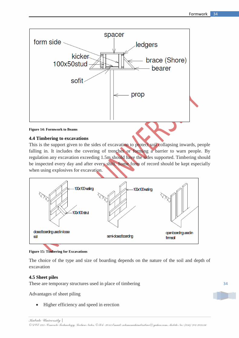
Kabale University | ©DCE 225–Concrete Technology, Lecture Notes. ©SA- 2013.Email: [email protected]. Mobile No: (256) 704 204556
34
34 Formwork
Figure 14: Formwork to Beams
4.4 Timbering to excavations
This is the support given to the sides of excavation to protect soil collapsing inwards, people
falling in. It includes the covering of trenches or forming a barrier to warn people. By
regulation any excavation exceeding 1.5m should have the sides supported. Timbering should
be inspected every day and after every shift. Some form of record should be kept especially
when using explosives for excavation.
Figure 15: Timbering for Excavations
The choice of the type and size of boarding depends on the nature of the soil and depth of
excavation
4.5 Sheet piles
These are temporary structures used in place of timbering
Advantages of sheet piling
Higher efficiency and speed in erection

Kabale University | ©DCE 225–Concrete Technology, Lecture Notes. ©SA- 2013.Email: [email protected]. Mobile No: (256) 704 204556
35
35 Formwork
Driven before excavation commences
Re-used
No strutting required
Precautions taken during excavation:
Proper access to excavation
Escape route/ provision be allowed
Ventilation
Warning signs should be installed
Figure 16: Sheet Piling
4.6 Cleaning and Storing Formwork
Formwork should be cleaned immediately after use and then stored until needed again. Clean
timber forms with a stiff brush to remove dust and grout. Use a timber scraper if necessary.
Do not use steel scrapers on timber or plywood forms. Steel forms should be lightly oiled to
prevent rusting if they are not to be used for some time. The main rule about storage is to
avoid doing any damage. Usually, more damage happens to formwork when it is not in use
than when it is being erected or struck.
4.7 References
1. Barry R.; The Construction of Buildings Volume I to Volume V.
2. Chudley, R. and Greeno, R. 1999. Building Construction Handbook. 3rd ed.
Butterworth-Heinemann, London
3. Butler, J.T. 1983. Elements of Administration for Building Students. 3rd ed.
Hutchison & Co., London.
4. Chudley R. Construction Technology Volumes I-V
5. Punmia B.C. 2007. Building Construction. Laxmi Publications (P) Ltd, 113, Golden
house, Daryaganj. New Dehli-110001
6. CE 223 Construction Technology II. Otim George, Kyambogo University

Kabale University | ©DCE 225–Concrete Technology, Lecture Notes. ©SA- 2013.Email: [email protected]. Mobile No: (256) 704 204556
36
36 Reinforcement
Chapter Five 5.0 Reinforcement
On site, reinforcement for concrete work must be properly stored and handled and it must be
fixed and kept in the correct position during construction.
5.1 Storage of Reinforcement
The main rules for good storage of reinforcement are:
Steel should be stored off the ground, especially on muddy sites. If the steel does
become dirtied with mud or clay, hose it down and use scrubbing brushes to clean it.
Steel should be stored away from workshops where oil and greases are used. Any oil
or grease on the steel should be scraped or rubbed off and the steel should then be
washed down with a strong detergent.
Loose rust and mill scale must be removed from the steel, using scrapers or wire
brushes, before the steel is fixed in position. Rust or scale that sticks firmly onto the
steel does not have to be removed.
5.2 Fixing Reinforcement in Place
Reinforcement must be fixed in the correct position and care must be taken to keep it in the
correct position while concrete is being placed and compacted.
The important points that require checking and supervision are:
All reinforcing bars and mesh must be fixed in the positions shown on the engineer‟s
drawings.
The bars must be properly tied together with soft wire and the long ends of the wires
must be clipped off.
Sufficient spacers must be used to make sure that the correct concrete cover to the
reinforcement is obtained in the whole structure.
Spacers shall be made of well cured mortar. Wooden blocks, pieces of stone or brick
must not be used for spacers.
Spacers must be securely fixed to the reinforcement. They must not be able to rotate
or move out of position when the concrete is being placed and compacted.
Steel must not be trampled or pushed out of position by the concreting gang or the
placing equipment.
5.3 Uses of Steel Reinforcement
Steel reinforcement is routinely used in reinforced concrete structures to augment the
relatively low inherent tensile strength of concrete. It is also used:
to carry shear, compressive and torsional forces in excess of concrete capacity
to control cracking of concrete members under working loads or as a result of early
thermal effects
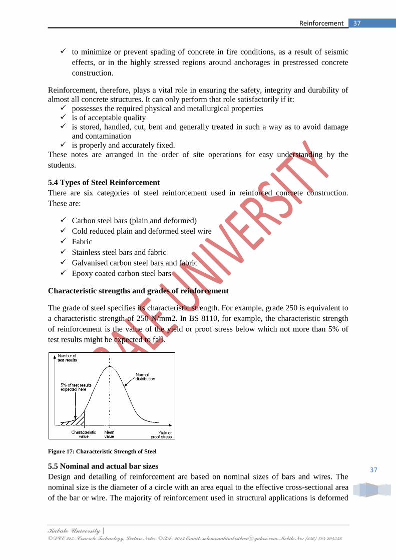
Kabale University | ©DCE 225–Concrete Technology, Lecture Notes. ©SA- 2013.Email: [email protected]. Mobile No: (256) 704 204556
37
37 Reinforcement
to minimize or prevent spading of concrete in fire conditions, as a result of seismic
effects, or in the highly stressed regions around anchorages in prestressed concrete
construction.
Reinforcement, therefore, plays a vital role in ensuring the safety, integrity and durability of
almost all concrete structures. It can only perform that role satisfactorily if it:
possesses the required physical and metallurgical properties
is of acceptable quality
is stored, handled, cut, bent and generally treated in such a way as to avoid damage
and contamination
is properly and accurately fixed.
These notes are arranged in the order of site operations for easy understanding by the
students.
5.4 Types of Steel Reinforcement
There are six categories of steel reinforcement used in reinforced concrete construction.
These are:
Carbon steel bars (plain and deformed)
Cold reduced plain and deformed steel wire
Fabric
Stainless steel bars and fabric
Galvanised carbon steel bars and fabric
Epoxy coated carbon steel bars
Characteristic strengths and grades of reinforcement
The grade of steel specifies its characteristic strength. For example, grade 250 is equivalent to
a characteristic strength of 250 N/mm2. In BS 8110, for example, the characteristic strength
of reinforcement is the value of the yield or proof stress below which not more than 5% of
test results might be expected to fall.
Figure 17: Characteristic Strength of Steel
5.5 Nominal and actual bar sizes
Design and detailing of reinforcement are based on nominal sizes of bars and wires. The
nominal size is the diameter of a circle with an area equal to the effective cross-sectional area
of the bar or wire. The majority of reinforcement used in structural applications is deformed

Kabale University | ©DCE 225–Concrete Technology, Lecture Notes. ©SA- 2013.Email: [email protected]. Mobile No: (256) 704 204556
38
38 Reinforcement
(see page 14); many bars are ribbed and are, therefore, not of circular section. As a result, the
actual sizes of bars as measured across the ribs will be greater than the nominal sizes.
5.6 Drawings and Schedules
It is essential that all site staff associated with reinforced concrete structures are able to
understand reinforcement drawings and schedules. This is because they will invariably be
called upon at some stage in a contract to carry out one or more of the following tasks:
Check "fixability" of the detailed reinforcement and effect on construction sequences.
Check drawings and schedules for errors and inconsistencies.
Schedule the reinforcement (if not already done).
Order reinforcement and accessories and programme deliveries to suit construction.
Check deliveries to ensure they contain the correct reinforcement.
Answer queries from steel fixers and resolve problems (in consultation with the
designer if necessary).
Check fixed reinforcement before starting to place concrete
Determine reinforcement tonnages for measurement purposes.
The importance of good detailing and scheduling
Good detailing and scheduling of reinforcement helps the construction process considerably
by minimizing costs, delays and disputes, by easing the steel fixer‟s task and by providing the
contractor with a certain amount of flexibility both in fixing and in construction staging. Bad
detailing and scheduling, on the other hand, can prove extremely costly and detrimental to
construction.
Notation for bar types and grades
The table shows a full list based on BS 4466.
Figure 18: Bar Notations and Grades
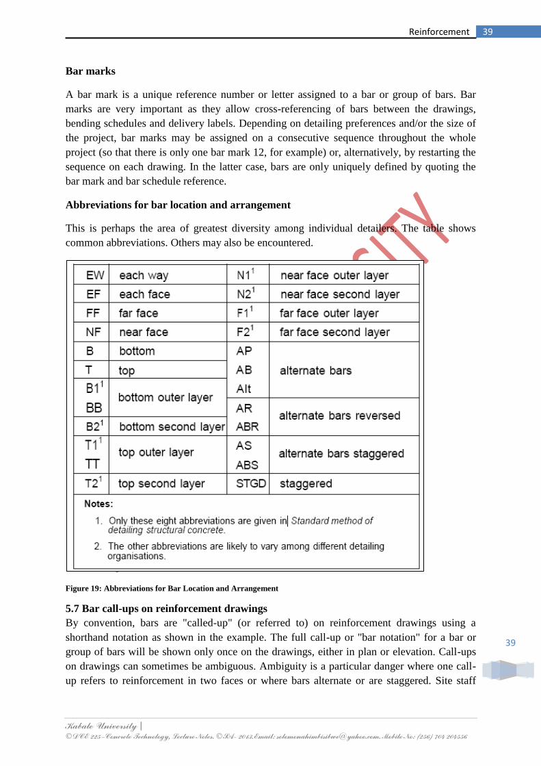
Kabale University | ©DCE 225–Concrete Technology, Lecture Notes. ©SA- 2013.Email: [email protected]. Mobile No: (256) 704 204556
39
39 Reinforcement
Bar marks
A bar mark is a unique reference number or letter assigned to a bar or group of bars. Bar
marks are very important as they allow cross-referencing of bars between the drawings,
bending schedules and delivery labels. Depending on detailing preferences and/or the size of
the project, bar marks may be assigned on a consecutive sequence throughout the whole
project (so that there is only one bar mark 12, for example) or, alternatively, by restarting the
sequence on each drawing. In the latter case, bars are only uniquely defined by quoting the
bar mark and bar schedule reference.
Abbreviations for bar location and arrangement
This is perhaps the area of greatest diversity among individual detailers. The table shows
common abbreviations. Others may also be encountered.
Figure 19: Abbreviations for Bar Location and Arrangement
5.7 Bar call-ups on reinforcement drawings
By convention, bars are "called-up" (or referred to) on reinforcement drawings using a
shorthand notation as shown in the example. The full call-up or "bar notation" for a bar or
group of bars will be shown only once on the drawings, either in plan or elevation. Call-ups
on drawings can sometimes be ambiguous. Ambiguity is a particular danger where one call-
up refers to reinforcement in two faces or where bars alternate or are staggered. Site staff

Kabale University | ©DCE 225–Concrete Technology, Lecture Notes. ©SA- 2013.Email: [email protected]. Mobile No: (256) 704 204556
40
40 Reinforcement
should always be on the lookout for erroneous or ambiguous call-ups. The designer or
detailer must always be consulted in cases of doubt.
Figure 20: Bar Call-ups

Kabale University | ©DCE 225–Concrete Technology, Lecture Notes. ©SA- 2013.Email: [email protected]. Mobile No: (256) 704 204556
41
41 Reinforcement
Drawings and Schedules
Figure 21: Bar Schedules and Arrangement

Kabale University | ©DCE 225–Concrete Technology, Lecture Notes. ©SA- 2013.Email: [email protected]. Mobile No: (256) 704 204556
42
42 Reinforcement
5.8 Shape codes
A shape code is a two digit code which uniquely defines the shape of a reinforcing bar. There
are essentially three groups of shapes for bar reinforcement:
Preferred shapes to BS 4466 (see Endpapers, Table A).
"Other" shapes to BS 4466 (see pages 31 and 32).
Shape code 99. This is considered a group in its own right as it contains all bent
shapes which do not fall into either of the preceding two categories.
Preferred shapes
Figure 22: Preferred Standard Shapes for Reinforcement

Kabale University | ©DCE 225–Concrete Technology, Lecture Notes. ©SA- 2013.Email: [email protected]. Mobile No: (256) 704 204556
43
43 Reinforcement
Other" shapes
Figure 23: Other Preferred Standard Shapes I

Kabale University | ©DCE 225–Concrete Technology, Lecture Notes. ©SA- 2013.Email: [email protected]. Mobile No: (256) 704 204556
44
44 Reinforcement
Other" shapes
Figure 24: Other Preferred Standard Shapes II
Unlike the other two categories, shape code 99 bars require dimensioned sketches to define
them fully. These sketches are shown on the bending schedule. The shape code for a bar does
not appear anywhere in the call-up for the bar on the reinforcement drawing.
5.9 Bending schedules for bar reinforcement
Shapes and dimensions of bars cannot in general be deduced from the reinforcement
drawings in isolation. The main function of the bending schedule is to define exactly the
shape of each bar within a group of bars having the same bar mark.

Kabale University | ©DCE 225–Concrete Technology, Lecture Notes. ©SA- 2013.Email: [email protected]. Mobile No: (256) 704 204556
45
45 Reinforcement
A standard layout of the bar bending schedule is given in BS 4466. The following points are
also worthy of note:
The exact layout or format of bending schedule varies from one organisation to
another, though most are based on the BS 4466 format.
The schedules may be produced by hand or by computer (the latter becoming
increasingly common).
Schedules normally contain information concerning weights of reinforcement, though
this aspect is not covered by BS 4466.
Bending schedules may or may not form part of the contract documents. Where they
do not, the contractor's staff will normally prepare schedules for ordering purposes.
Bars are grouped together for each structural unit. For example, in a building bars
may be listed floor by floor.
In accordance with BS 4466, each sheet in a bending schedule must show the last three digits
of the drawing number to which it relates, the schedule number and the revision letter (if
appropriate). This combination is called the bar schedule reference or bending schedule
reference
For example: bar schedule reference 051 02 A could mean schedule number 02 (revision A)
relating to drawing 2051. A simple bar bending schedule relating to a small pad footing is
shown herein.
Figure 25: Presentation of Footing Reinforcement

Kabale University | ©DCE 225–Concrete Technology, Lecture Notes. ©SA- 2013.Email: [email protected]. Mobile No: (256) 704 204556
46
46 Reinforcement
Figure 26: Simple Bar Bending Schedule in Relation to Figure 25

Kabale University | ©DCE 225–Concrete Technology, Lecture Notes. ©SA- 2013.Email: [email protected]. Mobile No: (256) 704 204556
47
47 Reinforcement
Example:
a) Give three reasons why steel reinforcement are bent (3 marks)
b) Explain the following bar notations ; 12Y 128-120 EW T (2 marks)
c) The figure below shows a footing. Show all calculations to obtain the unmber of bars
in
i. Bar mark 1
ii. Bar mark 2
iii. Bar mark 3 (7
marks)
d) Prepare a simple bar bending schedule relating to the pad footing shown herein (7
marks)
Figure 27: Footing Details for Practice Example
Kabale University | ©DCE 225–Concrete Technology, Lecture Notes. ©SA- 2013.Email: [email protected]. Mobile No: (256) 704 204556
48
48 Reinforcement
5.10 References
1. BS 4482, Specification for cold reduced steel wire for the reinforcement of concrete.
2. SANS 7801/ISO 7801, Metallic materials – Wire – Reverse bend test
3. SANS 6892/ISO 6892, Metallic materials – Tensile testing at ambient temperature
4. BS 8007, Code of practice for design of concrete structures for retaining aqueous liquids.
5. SABS 82, Bending dimensions of bars for concrete reinforcement.
6. SABS 920, Steel bars for concrete reinforcement.
7. SABS 1024, Welded steel fabric for reinforcement of concrete.
8. SABS 0100-1, The structural use of concrete – Part 1: Design.
9. SABS 0100-2, The structural use of concrete – Part 2: Materials and execution of work.
10. SABS 0143, Building drawing practice.
Kabale University | ©DCE 225–Concrete Technology, Lecture Notes. ©SA- 2013.Email: [email protected]. Mobile No: (256) 704 204556
49
49 Concrete Mix Design
Chapter Six 6.0 Concrete Mix Design
Concrete like other engineering materials needs to be designed for properties like strength,
durability, workability and cohesion. Concrete mix design is the science of deciding relative
proportions of ingredients of concrete, to achieve the desired properties in the most
economical way.
6.1 Advantages of mix design
Mix design aims to achieve good quality concrete at site economically.
1. Quality concrete means
Better strength
Better imperviousness and durability
Dense and homogeneous concrete
2. Economy
Economy in cement consumption; It is possible to save up to 15% of
cement for C20 grade of concrete with the help of concrete mix design.
In fact higher the grade of concrete more are the savings. Lower cement
content also results in lower heat of hydration and hence reduces
shrinkage cracks.
Best use of available materials: Site conditions often restrict the quality
and quantity of ingredient materials. Concrete mix design offers a lot of
flexibility on type of aggregates to be used in mix design. Mix design
can give an economical solution based on the available materials if they
meet the basic IS requirements. This can lead to saving in transportation
costs from longer distances.
Other properties: Mix design can help us to achieve form finishes, high
early strengths for early deshuttering, concrete with better flexural
strengths, concrete with pumpability and concrete with lower densities.
In concrete mix design, we determine the relative proportions of ingredients of concrete to
achieve desired strength & workability in a most economical way.
6.2 Method of Concrete Mix Design
There are various methods in use with varying merits and demerits but for the purpose of this
course, only the DoE method will be reviewed. This method borrows from the IS method of
mix design to obtain the curve for cement strength and the water cement ratio.
The DoE method overcomes some limitations of IS method. In DoE method, the fine
aggregate content is a function of 600micron passing fraction of sand and not the zone of
sand. The 600-micron passing fraction emerges as the most critical parameter governing the
cohesion and workability of concrete mix. Thus sand content in DoE method is more
sensitive to changes in fineness of sand when compared to the IS method. The sand content is

Kabale University | ©DCE 225–Concrete Technology, Lecture Notes. ©SA- 2013.Email: [email protected]. Mobile No: (256) 704 204556
50
50 Concrete Mix Design
also adjusted as per workability of mix. It is well accepted that higher the workability greater
is the fine aggregate required to maintain cohesion in the mix. The water content per m3 is
recommended based on workability requirement given in terms of slump and Vee Bee time.
It recommends different water contents for crushed aggregates and for natural aggregates.
The quantities of fine and coarse aggregates are calculated based on plastic density plotted
from fig 4 Annexure III (page no 68). However the DoE method allows simple correction in
aggregate quantities for actual plastic density obtained at laboratory.
The DoE method also suffers from some limitations.
The fine aggregates content calculated from DoE method often is on the higher side
resulting in over sandy mixes. For zone 1 coarse sand (600micron fraction 15 to 20%)
the sand content may exceed 50% for moderate workability of 30mm to 60mm slump.
The fine aggregate content cannot be adjusted for different cement contents. Hence a
rich mix with cement of 400Kg/m3 will have the same fine aggregate proportion, as a
lean mix with 300kg/m3 cement for given sand. Thus richer mixes may not be as
workable because of higher fines, when compared to mixes obtained from the IS
method.
The DoE method also does not take into account the effect of the surface texture and
flakiness of aggregate on sand and water content although it distinguishes between
crushed stone aggregates and natural aggregates.
The DoE method does not have a specific method of combining 10mm aggregates
with 20 mm aggregates.
No specific graphs are available (to estimate fine aggregate content) for maximum
size of aggregates between 20and 40 mm.
The DoE method follows these basic steps.
Find the target mean strength
Determine the curve of cement based on its strength
Determine water/cement ratio
Determine cement content
Determine fine and coarse aggregate proportions
Illustration:
Consider a mix design for M30 grade of concrete, having moderate workability (Slump range
50mm to 75mm).
6.3 Material Properties
Cement 53 grade (Although, actual 28 days compressive strength = 63 N/mm2)
Fine aggregate
600 micron passing = 32 %; Specific gravity = 2.75
Coarse aggregate

Kabale University | ©DCE 225–Concrete Technology, Lecture Notes. ©SA- 2013.Email: [email protected]. Mobile No: (256) 704 204556
51
51 Concrete Mix Design
20mm - Specific gravity - 2.95; Dry Rodded bulk density – 1600 Kg/m3
10mm - Specific gravity 2.86; Dry Rodded bulk density – 1700 Kg/
Solution:
2.1 Find the target mean strength
Concrete is designed for strength higher than characteristic strength as a margin for statistical
variation in results and variation in degree of control exercised at site. This higher strength is
defined as the target mean strength. It is calculated as follows:
K= Himsworth Coefficient is taken as 1.65 for 5 % probability of failure.
= Standard deviation
Say for M30 grade of concrete, K=1.65 (for 5% failure) and Standard Deviation, = 5 N /
mm2.
Target Mean Strength = 30 + 1.65 * 5 == 38.25 N/mm2
2.2 Determine the curve of cement based on its strength.
The strength of cement is determined either by conventional methods given in IS 4031- 1988
Part 6 or by accelerated curing reference mix method mentioned in IS 10262 –1982 page15
(Appendix B Clause 3.1.1.) The cement is classified into various curves based on the strength
of cement.
Curve Strength of Cement (N/mm2)
A 31.9 to 36.8 N/mm2
B 36.8 to 41.7 N/mm2
C 41.7 to 46.6 N/mm2
D 46.6 to 51.5 N/mm2
E 51.5 to 56.4 N/mm2
F 56.4 to 61.3 N/mm2
After selecting the appropriate curve based on the strength of cement, water/cement ratio is
interpolated for a given target mean strength.
2.3 Determine water/cement ratio
The relation between Target Mean Strength and water cement ratio for different cement
curves is given in IS 10262 Fig 2 (Refer Annexure II page 61 of Durocrete Mix Design

Kabale University | ©DCE 225–Concrete Technology, Lecture Notes. ©SA- 2013.Email: [email protected]. Mobile No: (256) 704 204556
52
52 Concrete Mix Design
Manual. Once the cement curve is fixed, water/cement ratio required for achieving the target
mean strength can be interpolated (Refer Appendix B).
For Example
For F curve and Target Mean Strength of 37; the water cement ratio is 0.48
For F curve and target mean strength of 38.25; the water cement ratio is 0.46
2.4 Finding cement content
Most of the mix design methods find cement content with following formula:
Water /cement ratio =
Weight of cement =
Weight of water required per m3 also called as water demand.
Water demand depends on:
i. Required Workability of concrete: Higher the workability required greater is the water
demand.
ii. Aggregate properties: Fineness and silt content of fine aggregate, size, shape and
flakiness of coarse aggregate, type of aggregate e.g. crushed, uncrushed.
iii. Use of admixtures: Plasticizers will reduce the water demand
Different mix design methods give empirical relations to find the water demand. Say, we
want to find water demand for 20 mm maximum size of crushed aggregate and natural sand
of zone II (F.M. = 3.0) for a slump range of 60 to 80 mm (compaction factor = 0.9).
We will select water demand for 30 to 60mm range.
Water demand for natural fine aggregate = 180lit.
Water demand for crushed coarse 20mm max size aggregate = 210 lit.
Water Demand = 2/3 x 180+ 1/3 x 210 = 120 + 70= 190 lit.
Cement Content =190/0.46 = 413.04.
2.5 Determine fine and coarse aggregate content:
The fine aggregate to coarse aggregate ratio is determined in different methods as
follows:
Sand Content for slump range of 30 to 60 mm and 30% 600 micron passing fraction
in sand is calculated from fig 2 as 42%
Average specific gravity of combined aggregates is calculated as follows: - = 0.42 x
2.75 + 0.58 x 2.89 = 2.83
Plastic Density of concrete is interpolated from fig 4 Annexure 4 as 2525kg/m3.
Total aggregate content per m3 is calculated as 2525 – 416 -190 =1919Kg
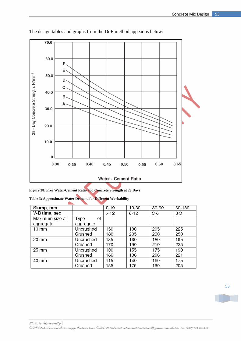
Kabale University | ©DCE 225–Concrete Technology, Lecture Notes. ©SA- 2013.Email: [email protected]. Mobile No: (256) 704 204556
53
53 Concrete Mix Design
The design tables and graphs from the DoE method appear as below:
Figure 28: Free Water/Cement Ratio and Concrete Strength at 28 Days
Table 3: Approximate Water Demand for Different Workability

Kabale University | ©DCE 225–Concrete Technology, Lecture Notes. ©SA- 2013.Email: [email protected]. Mobile No: (256) 704 204556
54
54 Concrete Mix Design
Notes:
i. For different types of coarse and fine aggregate, the free water content is estimated as
2/3 WFA + 1/3 WCA where, WFA = free water content appropriate to the type of the
fine aggregate, and WCA = free water content appropriate to the type of the coarse
aggregate
ii. Values interpolated for 25 mm maximum size of aggregate.
Example:
a) A margin is added to the minimum characteristic strength in the concrete mix design.
Explain this in detail. (5 marks)
b) Design concrete using the D.O.E method of mix design given the following
i. Characteristic strength/ compressive strength =30N/mm2
at 28 days
ii. Proportion defective = 5%
iii. Standard deviation = 8 N/mm2
iv. Cement type = OPC
v. Aggregate type
Coarse uncrushed
Fine uncrushed
vi. Slump =10-30mm
vii. Maximum Aggregate Size = 20mm
viii. Minimum Cement Content = 290kg/m3
ix. Relative Density of aggregates =2.6 kg/ m3
x. Percentage passing through 600 sieve = 40%
xi. Calculate the batch quantity of 0.05 m3
(15 marks)
6.4 References
1. PRASAD, G.V.K. and LOKESH BABU, L.V.R., Use of ground granulated blast
furnace slag (GGBS) for durable concrete, Proceedings of the Fifth International
conference on concrete technology for developing countries, Vol. 1, 17-19 November
1999, New Delhi, pp. II-12 to II-22.
2. NATARAJA, M.C., REDDY, B.M.R., BHAVANISHANKAR, S. and ETIGI,
Y.B.B., Mix design and some properties of cement concrete containing ground
granulated blast furnace slag, Proceedings of the second international symposium on
concrete technology for sustainable development with emphasis on infrastructure, 27
February - 3 March, 2005, Hyderabad, India, pp. 491-499
3. MAITI, S.C. and JAIN, N.K., Mix proportioning of superplasticed flash concrete,
Proceedings of the Fifth International conference on concrete technology for
developing countries, Vol. 2, 1999, New Delhi, pp. VI-106 to VI-113.
4. KAMAL, NAYAN, Blended cement concrete in Delhi Metro Rail Project,
Proceedings of the second International symposium on concrete technology for
sustainable development with emphasis on infrastructure, February 27 – March 3,
2005, Hyderabad, pp. 397-408.

Kabale University |
©DCE 225–Concrete Technology, Lecture Notes. ©SA- 2013.Email: [email protected]. Mobile No: (256) 704 204556
55 Concrete Mix Design
55
Figure 29: Recommended proportions of fine aggregate passing a 600μ sieve

Kabale University |
©DCE 225–Concrete Technology, Lecture Notes. ©SA- 2013.Email: [email protected]. Mobile No: (256) 704 204556
56 Concrete Mix Design
56
Figure 30: Recommended proportions of fine aggregate passing a 600μ sieve I

Kabale University |
©DCE 225–Concrete Technology, Lecture Notes. ©SA- 2013.Email: [email protected]. Mobile No: (256) 704 204556
57 Concrete Mix Design
57
Figure 31: Recommended proportions of fine aggregate passing a 600μ sieve II

Kabale University |
©DCE 225–Concrete Technology, Lecture Notes. ©SA- 2013.Email: [email protected]. Mobile No: (256) 704 204556
58 Concrete Mix Design
58
Figure 32: Wet density of fully compacted concrete and relative densities of aggregate