Nuclear Engineering and Technology - Korea Science
15
Original Article Experimental evaluation of fatigue strength for small diameter socket welded joints under vibration loading condition Chang-Young Oh * , Jun-Ho Lee, Dong-Woo Kim, Sang-Hoon Lee Korea Institute of Materials Science, Changwon, 51508, South Korea article info Article history: Received 25 November 2020 Received in revised form 21 April 2021 Accepted 28 May 2021 Available online 12 June 2021 Keywords: Socket welded joints Fatigue strength Small-bore piping Vibration loading Fabrication and repair technique abstract To investigate how the fabrication and repair of socket welded joints could be used to enhance fatigue resistance under vibration condition, experimental test data of installation conditions that potentially influence fatigue strength were analyzed with the SeN curve. It was found that the decreasing fatigue strength of stainless steel socket welded joints was attributed to the effect of high heat input of welding process. The effect of welding method, slip-on gap and radial-gap conditions on fatigue strength was insignificant. The test data of repair technique application, 2 1 leg length and of socket weld overlay, clearly showed higher fatigue strength but there was a limitation for higher stress region because of the weld toe crack. © 2021 Korean Nuclear Society, Published by Elsevier Korea LLC. This is an open access article under the CC BY-NC-ND license (http://creativecommons.org/licenses/by-nc-nd/4.0/). 1. Introduction Socket welded joints are generally used for pipes of small-bore piping because of design and manufacturing advantages. Socket welded joint is a kind of fillet weld applied to a piping system, and it is known to have low fatigue strength compared with butt welded joint. In spite of the weakness of the weld integrity, the use of socket welded joints in nuclear power plants is allowed in ASME B&PV Code Sec. III [1]. For ASME safety classes 1 and 2 piping, socket welded joints are limited to the nominal pipe size (NPS) of 2 inches [1]. There are usually about 40,000 socket welded joints used for drain or bypass piping in one typical 1000 MWe PWR plants [2e4]. A number of failures and leaks have been reported in socket welded joints [3,5]. Prior research has indicated that failures of socket welded joints are caused by vibration fatigue [6e11]. In order to investigate the effect parameters of fatigue for socket welded joints, Higuchi et al. conducted experimental test using rotation bending and a four point bending condition [6,7]. The effect of socket weld leg length, residual stress and axial gap on fatigue strength under vibration condition was reported by EPRI [8,9]. However, there are no fatigue behaviour results for various weld fabrication and installation conditions, which are including fracture morphologies and surface analyses. The welding method, welding heat input condition, geometrical parameters, repairing methods can be considerable in the fabrication and installation fields. This paper addresses how fabrication and repair of the socket welded joints can be used to enhance fatigue resistance under vi- bration condition. First, socket welded joints using manual GTAW that are generally used in the fabrication and installation field were compared with the results of previous studies and a reference SeN curve was obtained. Then experimental test data of the considered parameters that potentially influence fatigue strength were analyzed with the reference curve. Additionally, fractographic an- alyses were conducted to investigate fatigue crack behaviour of the socket welded joints under vibration loading condition. Section 2 describes how experimental tests of socket welded joints under vibration condition were conducted. In Section 3, fatigue strength and failure trends are discussed by comparing the experimental results of the fabrication condition and fracture analyses. Section 4 concludes the present work. * Corresponding author. E-mail address: [email protected] (C.-Y. Oh). Contents lists available at ScienceDirect Nuclear Engineering and Technology journal homepage: www.elsevier.com/locate/net https://doi.org/10.1016/j.net.2021.05.036 1738-5733/© 2021 Korean Nuclear Society, Published by Elsevier Korea LLC. This is an open access article under the CC BY-NC-ND license (http://creativecommons.org/ licenses/by-nc-nd/4.0/). Nuclear Engineering and Technology 53 (2021) 3837e3851
-
Upload
khangminh22 -
Category
Documents
-
view
1 -
download
0
Transcript of Nuclear Engineering and Technology - Korea Science

lable at ScienceDirect
Nuclear Engineering and Technology 53 (2021) 3837e3851
Contents lists avai
Nuclear Engineering and Technology
journal homepage: www.elsevier .com/locate/net
Original Article
Experimental evaluation of fatigue strength for small diameter socketwelded joints under vibration loading condition
Chang-Young Oh*, Jun-Ho Lee, Dong-Woo Kim, Sang-Hoon LeeKorea Institute of Materials Science, Changwon, 51508, South Korea
a r t i c l e i n f o
Article history:Received 25 November 2020Received in revised form21 April 2021Accepted 28 May 2021Available online 12 June 2021
Keywords:Socket welded jointsFatigue strengthSmall-bore pipingVibration loadingFabrication and repair technique
* Corresponding author.E-mail address: [email protected] (C.-Y. Oh).
https://doi.org/10.1016/j.net.2021.05.0361738-5733/© 2021 Korean Nuclear Society, Publishedlicenses/by-nc-nd/4.0/).
a b s t r a c t
To investigate how the fabrication and repair of socket welded joints could be used to enhance fatigueresistance under vibration condition, experimental test data of installation conditions that potentiallyinfluence fatigue strength were analyzed with the SeN curve. It was found that the decreasing fatiguestrength of stainless steel socket welded joints was attributed to the effect of high heat input of weldingprocess. The effect of welding method, slip-on gap and radial-gap conditions on fatigue strength wasinsignificant. The test data of repair technique application, 2 � 1 leg length and of socket weld overlay,clearly showed higher fatigue strength but there was a limitation for higher stress region because of theweld toe crack.© 2021 Korean Nuclear Society, Published by Elsevier Korea LLC. This is an open access article under the
CC BY-NC-ND license (http://creativecommons.org/licenses/by-nc-nd/4.0/).
1. Introduction
Socket welded joints are generally used for pipes of small-borepiping because of design and manufacturing advantages. Socketwelded joint is a kind of fillet weld applied to a piping system, and itis known to have low fatigue strength compared with butt weldedjoint. In spite of the weakness of the weld integrity, the use ofsocket welded joints in nuclear power plants is allowed in ASMEB&PV Code Sec. III [1]. For ASME safety classes 1 and 2 piping,socket welded joints are limited to the nominal pipe size (NPS) of 2inches [1]. There are usually about 40,000 socket welded jointsused for drain or bypass piping in one typical 1000 MWe PWRplants [2e4]. A number of failures and leaks have been reported insocket welded joints [3,5].
Prior research has indicated that failures of socket welded jointsare caused by vibration fatigue [6e11]. In order to investigate theeffect parameters of fatigue for socket welded joints, Higuchi et al.conducted experimental test using rotation bending and a fourpoint bending condition [6,7]. The effect of socket weld leg length,residual stress and axial gap on fatigue strength under vibrationcondition was reported by EPRI [8,9]. However, there are no fatigue
by Elsevier Korea LLC. This is an
behaviour results for various weld fabrication and installationconditions, which are including fracture morphologies and surfaceanalyses. The welding method, welding heat input condition,geometrical parameters, repairing methods can be considerable inthe fabrication and installation fields.
This paper addresses how fabrication and repair of the socketwelded joints can be used to enhance fatigue resistance under vi-bration condition. First, socket welded joints using manual GTAWthat are generally used in the fabrication and installation field werecompared with the results of previous studies and a reference SeNcurve was obtained. Then experimental test data of the consideredparameters that potentially influence fatigue strength wereanalyzed with the reference curve. Additionally, fractographic an-alyses were conducted to investigate fatigue crack behaviour of thesocket welded joints under vibration loading condition. Section 2describes how experimental tests of socket welded joints undervibration condition were conducted. In Section 3, fatigue strengthand failure trends are discussed by comparing the experimentalresults of the fabrication condition and fracture analyses. Section 4concludes the present work.
open access article under the CC BY-NC-ND license (http://creativecommons.org/
Nomenclature
A amplitude of displacementD nominal outer diameterE elastic modulusI moment of inertiaL length of pipeM momenta acceleration of top flangemp mass of pipemt-f mass of top flangex displacement of top flangeu angular frequency
abbreviationsASME American Society of Mechanical EngineersB&PV boiler & pressure vesselsEPRI Electric Power Research InstituteFE Finite ElementGTAW Gas Tungsten Arc WeldingPWR Pressurized water reactorWPS Welding Procedure Specification
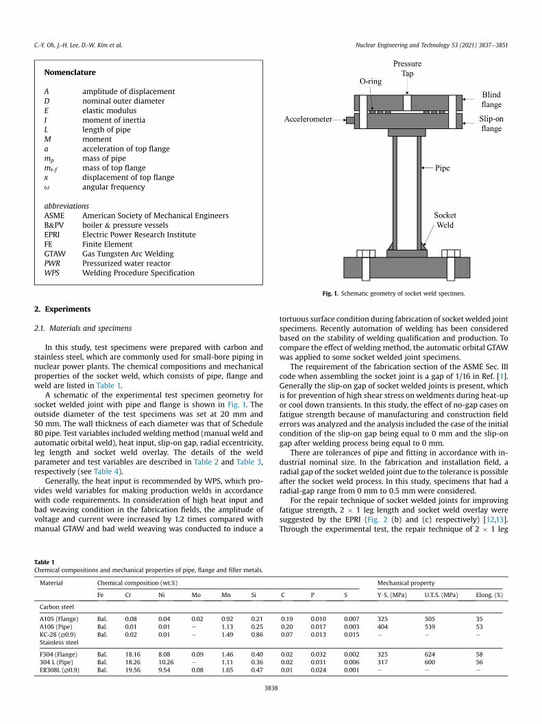
Fig. 1. Schematic geometry of socket weld specimen.
C.-Y. Oh, J.-H. Lee, D.-W. Kim et al. Nuclear Engineering and Technology 53 (2021) 3837e3851
2. Experiments
2.1. Materials and specimens
In this study, test specimens were prepared with carbon andstainless steel, which are commonly used for small-bore piping innuclear power plants. The chemical compositions and mechanicalproperties of the socket weld, which consists of pipe, flange andweld are listed in Table 1.
A schematic of the experimental test specimen geometry forsocket welded joint with pipe and flange is shown in Fig. 1. Theoutside diameter of the test specimens was set at 20 mm and50 mm. The wall thickness of each diameter was that of Schedule80 pipe. Test variables included welding method (manual weld andautomatic orbital weld), heat input, slip-on gap, radial eccentricity,leg length and socket weld overlay. The details of the weldparameter and test variables are described in Table 2 and Table 3,respectively (see Table 4).
Generally, the heat input is recommended by WPS, which pro-vides weld variables for making production welds in accordancewith code requirements. In consideration of high heat input andbad weaving condition in the fabrication fields, the amplitude ofvoltage and current were increased by 1.2 times compared withmanual GTAW and bad weld weaving was conducted to induce a
Table 1Chemical compositions and mechanical properties of pipe, flange and filler metals.
Material Chemical composition (wt.%)
Fe Cr Ni Mo Mn Si
Carbon steel
A105 (Flange) Bal. 0.08 0.04 0.02 0.92 0.21A106 (Pipe) Bal. 0.01 0.01 e 1.13 0.25KC-28 (∅0.9) Bal. 0.02 0.01 e 1.49 0.86Stainless steel
F304 (Flange) Bal. 18.16 8.08 0.09 1.46 0.40304 L (Pipe) Bal. 18.26 10.26 e 1.11 0.36ER308L (∅0.9) Bal. 19.56 9.54 0.08 1.65 0.47
3838
tortuous surface condition during fabrication of socket welded jointspecimens. Recently automation of welding has been consideredbased on the stability of welding qualification and production. Tocompare the effect of welding method, the automatic orbital GTAWwas applied to some socket welded joint specimens.
The requirement of the fabrication section of the ASME Sec. IIIcode when assembling the socket joint is a gap of 1/16 in Ref. [1].Generally the slip-on gap of socket welded joints is present, whichis for prevention of high shear stress on weldments during heat-upor cool down transients. In this study, the effect of no-gap cases onfatigue strength because of manufacturing and construction fielderrors was analyzed and the analysis included the case of the initialcondition of the slip-on gap being equal to 0 mm and the slip-ongap after welding process being equal to 0 mm.
There are tolerances of pipe and fitting in accordance with in-dustrial nominal size. In the fabrication and installation field, aradial gap of the socket welded joint due to the tolerance is possibleafter the socket weld process. In this study, specimens that had aradial-gap range from 0 mm to 0.5 mm were considered.
For the repair technique of socket welded joints for improvingfatigue strength, 2 � 1 leg length and socket weld overlay weresuggested by the EPRI (Fig. 2 (b) and (c) respectively) [12,13].Through the experimental test, the repair technique of 2 � 1 leg
Mechanical property
C P S Y$S. (MPa) U.T.S. (MPa) Elong. (%)
0.19 0.010 0.007 325 505 350.20 0.017 0.003 404 539 530.07 0.013 0.015 e e e
0.02 0.032 0.002 325 624 580.02 0.031 0.006 317 600 560.01 0.024 0.001 e e e
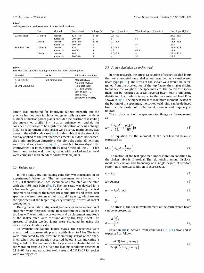
Table 2Welding condition and parameter of socket weld specimen.
Size Method Current (A) Voltage (V) Speed (in./min.) Wire feed speed (in./min.) Heat Input (kJ/in.)
Carbon steel 3/4 inch manual 123e170 13e15 2.7e4.0 e 24.0e56.7automatic 200/110 12 6 50 18.6
2 inch manual 156e220 13e16 2.9e6.7 e 18.2e76.1automatic 200/110 12 4 50 27.9
Stainless steel 3/4 inch manual 120 17 3.0e3.9 e 31.4e40.8automatic 160/80 11 4.5 46.5 18.8
2 inch manual 140 18 3.0e5.2 e 29.1e50.4automatic 200/110 12 4 50 29.5
Table 3Test Matrix for vibration loading condition for socket welded joints.
Material O. D. Fabrication condition
A106 (KC-28)/SS 304 L (ER308L)
20-mm/50-mm Manual GTAWAutomatic GTAWHigh heat input2 : 1 Leg LengthSlip-on gap ¼ 0EccentricitySocket weld Overlay
C.-Y. Oh, J.-H. Lee, D.-W. Kim et al. Nuclear Engineering and Technology 53 (2021) 3837e3851
length was suggested for improving fatigue strength but thepractice has not been implemented generically or system wide. Anumber of nuclear power plants consider the practice of installingthe uneven leg profile (2 � 1) as an enhancement and do notconsider the practice to be a system modification or design change[13]. The requirement of the socket weld overlay methodology wasgiven in the ASME code case [14]. It is desirable that the size of theoverlay applied to the test specimens meets, but does not exceed,the minimum design dimensions; therefore the design dimensionswere tested as shown in Fig. 2 (b) and (c). To investigate theimprovement of fatigue strength by repair method, the 2 � 1 leglength and socket weld overlay cases with cracked socket weldwere compared with standard socket welded joints.
2.2. Fatigue tests
In this study, vibration loading condition was considered in anexperimental fatigue test. The test specimens were bolted on a4 ft � 4 ft shaker table. Each specimen was mounted on the tablewith eight 5/8 inch bolts (Fig. 3). The test setup was devised for avibration fatigue test on the shaker table for shaking the testspecimens to produce the target stress amplitudes and cycles. Testspecimens were shaken near their natural frequency, which excitesthe specimens at the target frequency resulting in stress at socketwelded joints.
During the vibration fatigue test, frequencies and acceleration ofspecimen were measured using an accelerometer attached at thetop flange. The excitation acceleration and displacement amplitudeof the shaker table were constant during the fatigue test. Thestresses of socket welded joints were evaluated by using themeasured acceleration value.
To evaluate the fatigue failure status, the specimens werepressurized to a pneumatic pressure with air up to 5 bar. The testswere terminated by the pressure monitoring sensor of the spec-imen when depressurization occurred below 3 bar indicating afatigue failure. The endurance limit cycle was evaluated based onthe vibration fatigue life of various loading conditions reached at1.1 Eþ07 for standard socket weld cases and 2.0 Eþ07 for socketweld overlay cases.
3839
2.3. Stress calculation on socket weld
In prior research, the stress calculation of socket welded jointsthat were mounted on a shaker was regarded as a cantileveredbeam type [8e11]. The stress of the socket weld would be deter-mined from the acceleration of the top flange, the shaker drivingfrequency, the weight of the specimen etc. The bolted test speci-mens can be regarded as a cantilevered beam with a uniformlydistributed load, which is equal to the concentrated load P, asshown in Fig. 4. The highest stress of maximummoment located atthe bottom of the specimen, the socket weld joint, can be deducedfrom the relationship of displacement, moment and frequency asfollows.
The displacement of the specimen top flange can be expressedas
x¼ mt�f L
3
3EIþmpL3
8EI
!a (1)
The equation for the moment of the cantilevered beam isexpressed as
M¼�mt�f Lþ
12mpL
�a (2)
The motion of the test specimen under vibration condition bythe shaker table is sinusoidal. The relationship among displace-ment, acceleration and frequency of a single degree of freedomsystem in sinusoidal condition is expressed as
u¼2pf (3)
x¼Asinut (4)
a¼ � Au2sinut (5)
x¼ � au2 (6)
The stress of the socket weld moment of the cantilevered beamcan be expressed as
s¼M�D2
�I
(7)
Equation (8) is derived from equations (1)e(7) above and isexpressed as follows
s¼3aED
�2mt�f þmp
�2ðpfLÞ2
�8mt�f þmp
� (8)
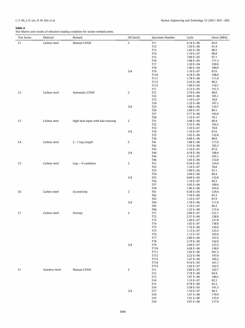
Table 4Test Matrix and results of vibration loading condition for socket welded joints.
Test Series Material Remark OD [inch] Specimen Number Cycle Stress [MPa]
C1 Carbon steel Manual GTAW 2 T11 6.18 Eþ06 85.0T12 1.20 Eþ06 91.4T13 1.82 Eþ06 88.5T14 1.10 Eþ07 68.8T15 7.00 Eþ05 97.1T16 1.08 Eþ05 171.3T17 1.20 Eþ04 350.0T18 1.40 Eþ04 340.0
3/4 T19 1.10 Eþ07 87.6T110 4.18 Eþ06 108.0T111 1.78 Eþ06 111.0T112 2.24 Eþ06 96.2T113 7.40 Eþ05 110.7T11 2.13 Eþ05 151.3
C2 Carbon steel Automatic GTAW 2 T21 2.79 Eþ06 98.0T22 4.03 Eþ06 105.1T23 1.10 Eþ07 78.8T24 1.32 Eþ06 107.1
3/4 T25 1.88 Eþ06 119.7T26 1.00 Eþ07 89.1T27 5.77 Eþ06 103.8T28 1.10 Eþ07 78.1
C3 Carbon steel High heat input with bad weaving 2 T31 5.48 Eþ06 80.4T32 3.33 Eþ06 102.2T33 1.10 Eþ07 70.8
3/4 T34 1.10 Eþ07 87.6T35 1.65 Eþ06 132.8T36 6.08 Eþ06 88.0
C4 Carbon steel 2 : 1 Leg Length 2 T41 1.88 Eþ06 117.0T42 3.33 Eþ06 102.2T43 1.10 Eþ07 87.9
3/4 T44 4.18 Eþ06 108.0T45 1.10 Eþ07 105.1T46 1.65 Eþ06 132.8
C5 Carbon steel Gap ¼ 0 condition 2 T51 6.54 Eþ05 124.4T52 1.10 Eþ07 76.8T53 7.00 Eþ05 97.1T54 3.94 Eþ06 80.4
3/4 T55 6.80 Eþ05 132.8T56 1.10 Eþ07 99.3T57 3.95 Eþ06 109.6T58 1.96 Eþ06 103.6
C6 Carbon steel Eccentricity 2 T61 6.38 Eþ05 124.4T62 7.59 Eþ06 83.3T63 1.10 Eþ07 87.9
3/4 T64 1.78 Eþ06 111.0T65 1.10 Eþ07 96.3T66 1.23 Eþ06 115.4
C7 Carbon steel Overlay 2 T71 2.00 Eþ07 121.7T72 2.37 Eþ06 128.8T73 1.20 Eþ07 127.8T74 1.63 Eþ07 138.0T75 1.76 Eþ06 156.9T75 1.13 Eþ07 125.5T76 1.13 Eþ07 165.0T77 2.80 Eþ06 155.5T78 2.79 Eþ06 142.0
3/4 T79 2.04 Eþ07 123.3T710 4.28 Eþ06 138.0T711 1.03 Eþ06 201.3T712 2.22 Eþ06 147.0T713 1.47 Eþ06 166.2T714 9.10 Eþ05 161.7T715 1.02 Eþ07 142.5
S1 Stainless Steel Manual GTAW 2 S11 2.80 Eþ05 162.7S12 2.78 Eþ06 94.4S13 1.87 Eþ06 100.2S14 1.10 Eþ07 82.3S15 6.78 Eþ06 92.3S16 5.58 Eþ05 141.3
3/4 S17 1.10 Eþ07 98.3S18 1.67 Eþ06 170.9S19 1.01 Eþ06 135.9S10 5.07 Eþ06 117.9
C.-Y. Oh, J.-H. Lee, D.-W. Kim et al. Nuclear Engineering and Technology 53 (2021) 3837e3851
3840
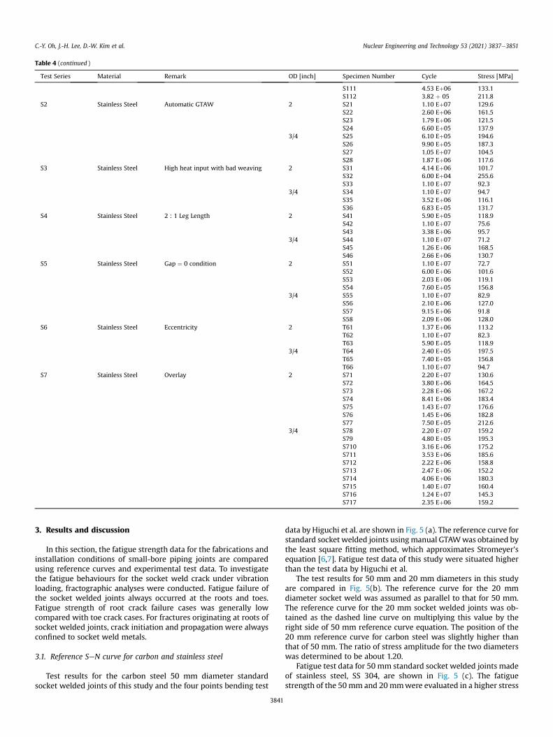
Table 4 (continued )
Test Series Material Remark OD [inch] Specimen Number Cycle Stress [MPa]
S111 4.53 Eþ06 133.1S112 3.82 þ 05 211.8
S2 Stainless Steel Automatic GTAW 2 S21 1.10 Eþ07 129.6S22 2.60 Eþ06 161.5S23 1.79 Eþ06 121.5S24 6.60 Eþ05 137.9
3/4 S25 6.10 Eþ05 194.6S26 9.90 Eþ05 187.3S27 1.05 Eþ07 104.5S28 1.87 Eþ06 117.6
S3 Stainless Steel High heat input with bad weaving 2 S31 4.14 Eþ06 101.7S32 6.00 Eþ04 255.6S33 1.10 Eþ07 92.3
3/4 S34 1.10 Eþ07 94.7S35 3.52 Eþ06 116.1S36 6.83 Eþ05 131.7
S4 Stainless Steel 2 : 1 Leg Length 2 S41 5.90 Eþ05 118.9S42 1.10 Eþ07 75.6S43 3.38 Eþ06 95.7
3/4 S44 1.10 Eþ07 71.2S45 1.26 Eþ06 168.5S46 2.66 Eþ06 130.7
S5 Stainless Steel Gap ¼ 0 condition 2 S51 1.10 Eþ07 72.7S52 6.00 Eþ06 101.6S53 2.03 Eþ06 119.1S54 7.60 Eþ05 156.8
3/4 S55 1.10 Eþ07 82.9S56 2.10 Eþ06 127.0S57 9.15 Eþ06 91.8S58 2.09 Eþ06 128.0
S6 Stainless Steel Eccentricity 2 T61 1.37 Eþ06 113.2T62 1.10 Eþ07 82.3T63 5.90 Eþ05 118.9
3/4 T64 2.40 Eþ05 197.5T65 7.40 Eþ05 156.8T66 1.10 Eþ07 94.7
S7 Stainless Steel Overlay 2 S71 2.20 Eþ07 130.6S72 3.80 Eþ06 164.5S73 2.28 Eþ06 167.2S74 8.41 Eþ06 183.4S75 1.43 Eþ07 176.6S76 1.45 Eþ06 182.8S77 7.50 Eþ05 212.6
3/4 S78 2.20 Eþ07 159.2S79 4.80 Eþ05 195.3S710 3.16 Eþ06 175.2S711 3.53 Eþ06 185.6S712 2.22 Eþ06 158.8S713 2.47 Eþ06 152.2S714 4.06 Eþ06 180.3S715 1.40 Eþ07 160.4S716 1.24 Eþ07 145.3S717 2.35 Eþ06 159.2
C.-Y. Oh, J.-H. Lee, D.-W. Kim et al. Nuclear Engineering and Technology 53 (2021) 3837e3851
3. Results and discussion
In this section, the fatigue strength data for the fabrications andinstallation conditions of small-bore piping joints are comparedusing reference curves and experimental test data. To investigatethe fatigue behaviours for the socket weld crack under vibrationloading, fractographic analyses were conducted. Fatigue failure ofthe socket welded joints always occurred at the roots and toes.Fatigue strength of root crack failure cases was generally lowcompared with toe crack cases. For fractures originating at roots ofsocket welded joints, crack initiation and propagation were alwaysconfined to socket weld metals.
3.1. Reference SeN curve for carbon and stainless steel
Test results for the carbon steel 50 mm diameter standardsocket welded joints of this study and the four points bending test
3841
data by Higuchi et al. are shown in Fig. 5 (a). The reference curve forstandard socket welded joints usingmanual GTAWwas obtained bythe least square fitting method, which approximates Stromeyer'sequation [6,7]. Fatigue test data of this study were situated higherthan the test data by Higuchi et al.
The test results for 50 mm and 20 mm diameters in this studyare compared in Fig. 5(b). The reference curve for the 20 mmdiameter socket weld was assumed as parallel to that for 50 mm.The reference curve for the 20 mm socket welded joints was ob-tained as the dashed line curve on multiplying this value by theright side of 50 mm reference curve equation. The position of the20 mm reference curve for carbon steel was slightly higher thanthat of 50 mm. The ratio of stress amplitude for the two diameterswas determined to be about 1.20.
Fatigue test data for 50 mm standard socket welded joints madeof stainless steel, SS 304, are shown in Fig. 5 (c). The fatiguestrength of the 50mm and 20mmwere evaluated in a higher stress
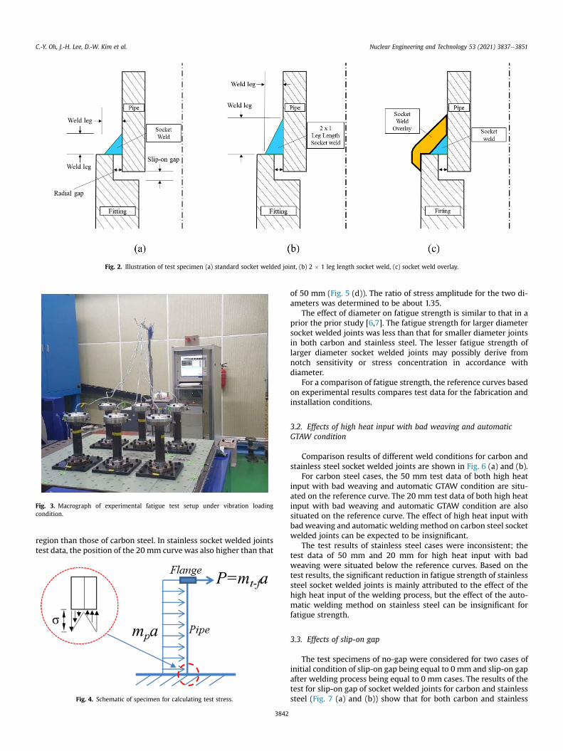
Fig. 2. Illustration of test specimen (a) standard socket welded joint, (b) 2 � 1 leg length socket weld, (c) socket weld overlay.
Fig. 3. Macrograph of experimental fatigue test setup under vibration loadingcondition.
C.-Y. Oh, J.-H. Lee, D.-W. Kim et al. Nuclear Engineering and Technology 53 (2021) 3837e3851
region than those of carbon steel. In stainless socket welded jointstest data, the position of the 20 mm curvewas also higher than that
Fig. 4. Schematic of specimen for calculating test stress.
3842
of 50 mm (Fig. 5 (d)). The ratio of stress amplitude for the two di-ameters was determined to be about 1.35.
The effect of diameter on fatigue strength is similar to that in aprior the prior study [6,7]. The fatigue strength for larger diametersocket welded joints was less than that for smaller diameter jointsin both carbon and stainless steel. The lesser fatigue strength oflarger diameter socket welded joints may possibly derive fromnotch sensitivity or stress concentration in accordance withdiameter.
For a comparison of fatigue strength, the reference curves basedon experimental results compares test data for the fabrication andinstallation conditions.
3.2. Effects of high heat input with bad weaving and automaticGTAW condition
Comparison results of different weld conditions for carbon andstainless steel socket welded joints are shown in Fig. 6 (a) and (b).
For carbon steel cases, the 50 mm test data of both high heatinput with bad weaving and automatic GTAW condition are situ-ated on the reference curve. The 20 mm test data of both high heatinput with bad weaving and automatic GTAW condition are alsosituated on the reference curve. The effect of high heat input withbad weaving and automatic welding method on carbon steel socketwelded joints can be expected to be insignificant.
The test results of stainless steel cases were inconsistent; thetest data of 50 mm and 20 mm for high heat input with badweaving were situated below the reference curves. Based on thetest results, the significant reduction in fatigue strength of stainlesssteel socket welded joints is mainly attributed to the effect of thehigh heat input of the welding process, but the effect of the auto-matic welding method on stainless steel can be insignificant forfatigue strength.
3.3. Effects of slip-on gap
The test specimens of no-gap were considered for two cases ofinitial condition of slip-on gap being equal to 0 mm and slip-on gapafter welding process being equal to 0 mm cases. The results of thetest for slip-on gap of socket welded joints for carbon and stainlesssteel (Fig. 7 (a) and (b)) show that for both carbon and stainless
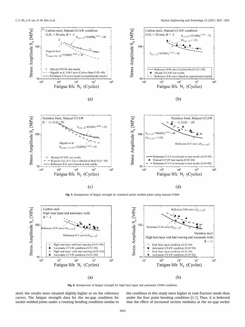
Fig. 5. Comparison of fatigue strength for standard socket welded joints using manual GTAW.
Fig. 6. Comparison of fatigue strength for high heat input and automatic GTAW condition.
C.-Y. Oh, J.-H. Lee, D.-W. Kim et al. Nuclear Engineering and Technology 53 (2021) 3837e3851
steel, the results were situated slightly higher or on the referencecurves. The fatigue strength data for the no-gap condition forsocket welded joints under a rotating bending condition similar to
3843
the condition in this study were higher in root-fracture mode thanunder the four point bending condition [6,7]. Thus, it is believedthat the effect of increased section modulus at the no-gap socket
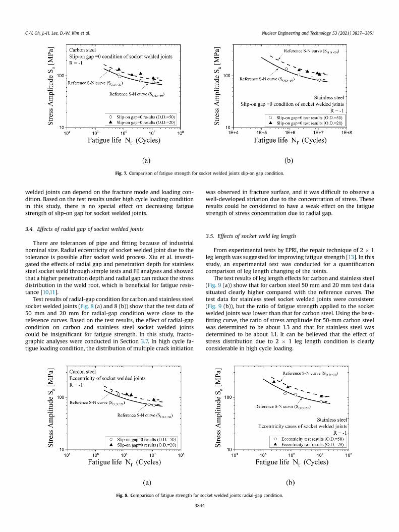
Fig. 7. Comparison of fatigue strength for socket welded joints slip-on gap condition.
C.-Y. Oh, J.-H. Lee, D.-W. Kim et al. Nuclear Engineering and Technology 53 (2021) 3837e3851
welded joints can depend on the fracture mode and loading con-dition. Based on the test results under high cycle loading conditionin this study, there is no special effect on decreasing fatiguestrength of slip-on gap for socket welded joints.
3.4. Effects of radial gap of socket welded joints
There are tolerances of pipe and fitting because of industrialnominal size. Radial eccentricity of socket welded joint due to thetolerance is possible after socket weld process. Xiu et al. investi-gated the effects of radial gap and penetration depth for stainlesssteel socket weld through simple tests and FE analyses and showedthat a higher penetration depth and radial gap can reduce the stressdistribution in the weld root, which is beneficial for fatigue resis-tance [10,11].
Test results of radial-gap condition for carbon and stainless steelsocket welded joints (Fig. 8 (a) and 8 (b)) show that the test data of50 mm and 20 mm for radial-gap condition were close to thereference curves. Based on the test results, the effect of radial-gapcondition on carbon and stainless steel socket welded jointscould be insignificant for fatigue strength. In this study, fracto-graphic analyses were conducted in Section 3.7. In high cycle fa-tigue loading condition, the distribution of multiple crack initiation
Fig. 8. Comparison of fatigue strength for so
3844
was observed in fracture surface, and it was difficult to observe awell-developed striation due to the concentration of stress. Theseresults could be considered to have a weak effect on the fatiguestrength of stress concentration due to radial gap.
3.5. Effects of socket weld leg length
From experimental tests by EPRI, the repair technique of 2 � 1leg length was suggested for improving fatigue strength [13]. In thisstudy, an experimental test was conducted for a quantificationcomparison of leg length changing of the joints.
The test results of leg length effects for carbon and stainless steel(Fig. 9 (a)) show that for carbon steel 50 mm and 20 mm test datasituated clearly higher compared with the reference curves. Thetest data for stainless steel socket welded joints were consistent(Fig. 9 (b)), but the ratio of fatigue strength applied to the socketwelded joints was lower than that for carbon steel. Using the best-fitting curve, the ratio of stress amplitude for 50-mm carbon steelwas determined to be about 1.3 and that for stainless steel wasdetermined to be about 1.1. It can be believed that the effect ofstress distribution due to 2 � 1 leg length condition is clearlyconsiderable in high cycle loading.
cket welded joints radial-gap condition.
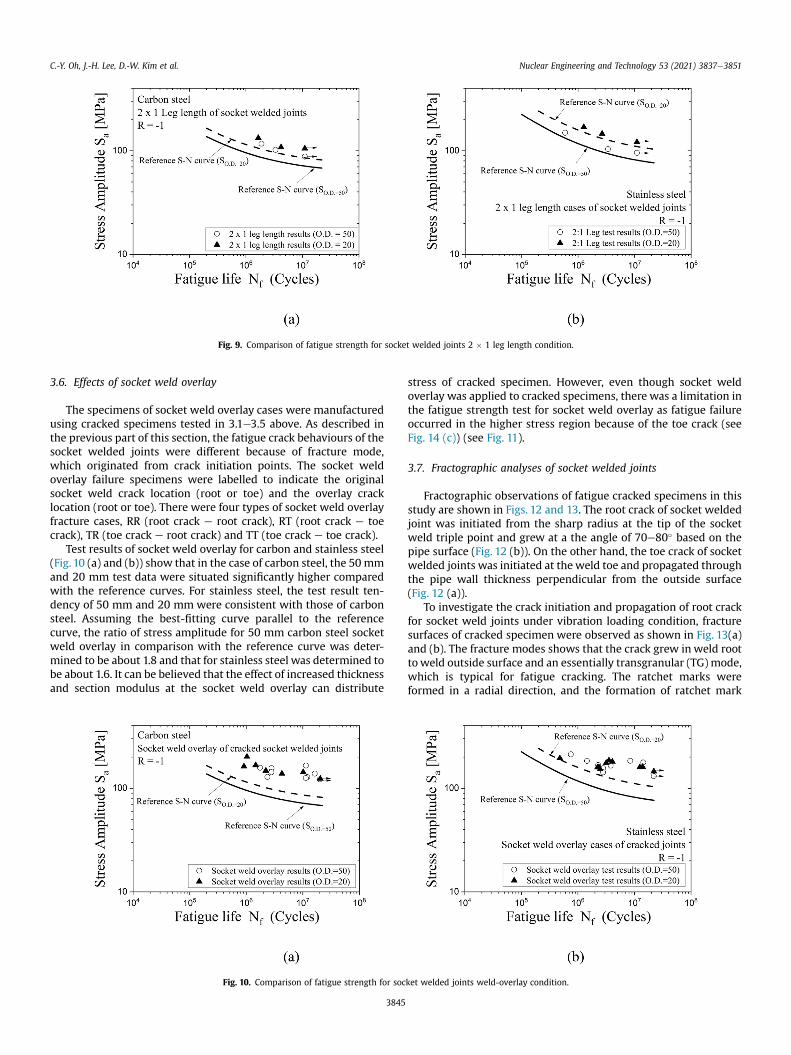
Fig. 9. Comparison of fatigue strength for socket welded joints 2 � 1 leg length condition.
C.-Y. Oh, J.-H. Lee, D.-W. Kim et al. Nuclear Engineering and Technology 53 (2021) 3837e3851
3.6. Effects of socket weld overlay
The specimens of socket weld overlay cases were manufacturedusing cracked specimens tested in 3.1e3.5 above. As described inthe previous part of this section, the fatigue crack behaviours of thesocket welded joints were different because of fracture mode,which originated from crack initiation points. The socket weldoverlay failure specimens were labelled to indicate the originalsocket weld crack location (root or toe) and the overlay cracklocation (root or toe). There were four types of socket weld overlayfracture cases, RR (root crack e root crack), RT (root crack e toecrack), TR (toe crack e root crack) and TT (toe crack e toe crack).
Test results of socket weld overlay for carbon and stainless steel(Fig. 10 (a) and (b)) show that in the case of carbon steel, the 50 mmand 20 mm test data were situated significantly higher comparedwith the reference curves. For stainless steel, the test result ten-dency of 50 mm and 20 mm were consistent with those of carbonsteel. Assuming the best-fitting curve parallel to the referencecurve, the ratio of stress amplitude for 50 mm carbon steel socketweld overlay in comparison with the reference curve was deter-mined to be about 1.8 and that for stainless steel was determined tobe about 1.6. It can be believed that the effect of increased thicknessand section modulus at the socket weld overlay can distribute
Fig. 10. Comparison of fatigue strength for soc
3845
stress of cracked specimen. However, even though socket weldoverlay was applied to cracked specimens, there was a limitation inthe fatigue strength test for socket weld overlay as fatigue failureoccurred in the higher stress region because of the toe crack (seeFig. 14 (c)) (see Fig. 11).
3.7. Fractographic analyses of socket welded joints
Fractographic observations of fatigue cracked specimens in thisstudy are shown in Figs. 12 and 13. The root crack of socket weldedjoint was initiated from the sharp radius at the tip of the socketweld triple point and grew at a the angle of 70e80� based on thepipe surface (Fig. 12 (b)). On the other hand, the toe crack of socketwelded joints was initiated at the weld toe and propagated throughthe pipe wall thickness perpendicular from the outside surface(Fig. 12 (a)).
To investigate the crack initiation and propagation of root crackfor socket weld joints under vibration loading condition, fracturesurfaces of cracked specimen were observed as shown in Fig. 13(a)and (b). The fracture modes shows that the crack grew in weld roottoweld outside surface and an essentially transgranular (TG) mode,which is typical for fatigue cracking. The ratchet marks wereformed in a radial direction, and the formation of ratchet mark
ket welded joints weld-overlay condition.
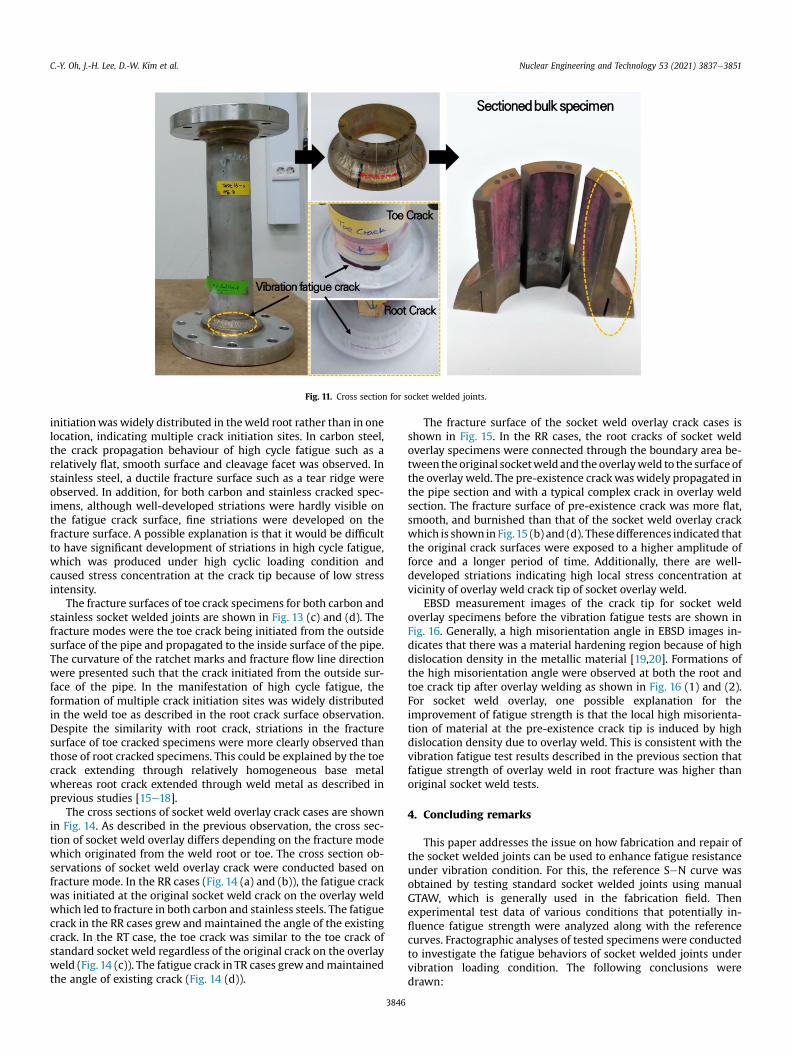
Fig. 11. Cross section for socket welded joints.
C.-Y. Oh, J.-H. Lee, D.-W. Kim et al. Nuclear Engineering and Technology 53 (2021) 3837e3851
initiationwas widely distributed in theweld root rather than in onelocation, indicating multiple crack initiation sites. In carbon steel,the crack propagation behaviour of high cycle fatigue such as arelatively flat, smooth surface and cleavage facet was observed. Instainless steel, a ductile fracture surface such as a tear ridge wereobserved. In addition, for both carbon and stainless cracked spec-imens, although well-developed striations were hardly visible onthe fatigue crack surface, fine striations were developed on thefracture surface. A possible explanation is that it would be difficultto have significant development of striations in high cycle fatigue,which was produced under high cyclic loading condition andcaused stress concentration at the crack tip because of low stressintensity.
The fracture surfaces of toe crack specimens for both carbon andstainless socket welded joints are shown in Fig. 13 (c) and (d). Thefracture modes were the toe crack being initiated from the outsidesurface of the pipe and propagated to the inside surface of the pipe.The curvature of the ratchet marks and fracture flow line directionwere presented such that the crack initiated from the outside sur-face of the pipe. In the manifestation of high cycle fatigue, theformation of multiple crack initiation sites was widely distributedin the weld toe as described in the root crack surface observation.Despite the similarity with root crack, striations in the fracturesurface of toe cracked specimens were more clearly observed thanthose of root cracked specimens. This could be explained by the toecrack extending through relatively homogeneous base metalwhereas root crack extended through weld metal as described inprevious studies [15e18].
The cross sections of socket weld overlay crack cases are shownin Fig. 14. As described in the previous observation, the cross sec-tion of socket weld overlay differs depending on the fracture modewhich originated from the weld root or toe. The cross section ob-servations of socket weld overlay crack were conducted based onfracture mode. In the RR cases (Fig. 14 (a) and (b)), the fatigue crackwas initiated at the original socket weld crack on the overlay weldwhich led to fracture in both carbon and stainless steels. The fatiguecrack in the RR cases grew and maintained the angle of the existingcrack. In the RT case, the toe crack was similar to the toe crack ofstandard socket weld regardless of the original crack on the overlayweld (Fig.14 (c)). The fatigue crack in TR cases grew andmaintainedthe angle of existing crack (Fig. 14 (d)).
3846
The fracture surface of the socket weld overlay crack cases isshown in Fig. 15. In the RR cases, the root cracks of socket weldoverlay specimens were connected through the boundary area be-tween the original socketweld and the overlayweld to the surface ofthe overlay weld. The pre-existence crackwaswidely propagated inthe pipe section and with a typical complex crack in overlay weldsection. The fracture surface of pre-existence crack was more flat,smooth, and burnished than that of the socket weld overlay crackwhich is shown in Fig.15 (b) and (d). These differences indicated thatthe original crack surfaces were exposed to a higher amplitude offorce and a longer period of time. Additionally, there are well-developed striations indicating high local stress concentration atvicinity of overlay weld crack tip of socket overlay weld.
EBSD measurement images of the crack tip for socket weldoverlay specimens before the vibration fatigue tests are shown inFig. 16. Generally, a high misorientation angle in EBSD images in-dicates that there was a material hardening region because of highdislocation density in the metallic material [19,20]. Formations ofthe high misorientation angle were observed at both the root andtoe crack tip after overlay welding as shown in Fig. 16 (1) and (2).For socket weld overlay, one possible explanation for theimprovement of fatigue strength is that the local high misorienta-tion of material at the pre-existence crack tip is induced by highdislocation density due to overlay weld. This is consistent with thevibration fatigue test results described in the previous section thatfatigue strength of overlay weld in root fracture was higher thanoriginal socket weld tests.
4. Concluding remarks
This paper addresses the issue on how fabrication and repair ofthe socket welded joints can be used to enhance fatigue resistanceunder vibration condition. For this, the reference SeN curve wasobtained by testing standard socket welded joints using manualGTAW, which is generally used in the fabrication field. Thenexperimental test data of various conditions that potentially in-fluence fatigue strength were analyzed along with the referencecurves. Fractographic analyses of tested specimens were conductedto investigate the fatigue behaviors of socket welded joints undervibration loading condition. The following conclusions weredrawn:
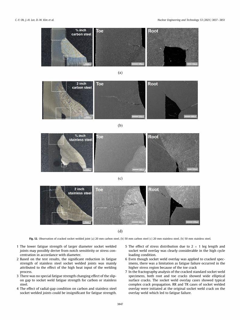
Fig. 12. Observation of cracked socket welded joint (a) 20 mm carbon steel, (b) 50 mm carbon steel (c) 20 mm stainless steel, (b) 50 mm stainless steel.
C.-Y. Oh, J.-H. Lee, D.-W. Kim et al. Nuclear Engineering and Technology 53 (2021) 3837e3851
1 The lower fatigue strength of larger diameter socket weldedjoints may possibly derive from notch sensitivity or stress con-centration in accordance with diameter.
2 Based on the test results, the significant reduction in fatiguestrength of stainless steel socket welded joints was mainlyattributed to the effect of the high heat input of the weldingprocess.
3 Therewas no special fatigue strength changing effect of the slip-on gap to socket weld fatigue strength for carbon or stainlesssteel.
4 The effect of radial-gap condition on carbon and stainless steelsocket welded joints could be insignificant for fatigue strength.
3847
5 The effect of stress distribution due to 2 � 1 leg length andsocket weld overlay was clearly considerable in the high cycleloading condition.
6 Even though socket weld overlay was applied to cracked spec-imens, there was a limitation as fatigue failure occurred in thehigher stress region because of the toe crack
7 In the fractography analysis of the cracked standard socket weldspecimens, both root and toe cracks showed wide ellipticalsurface cracks. The socket weld overlay cases showed typicalcomplex crack propagation. RR and TR cases of socket weldedoverlay were initiated at the original socket weld crack on theoverlay weld which led to fatigue failure.
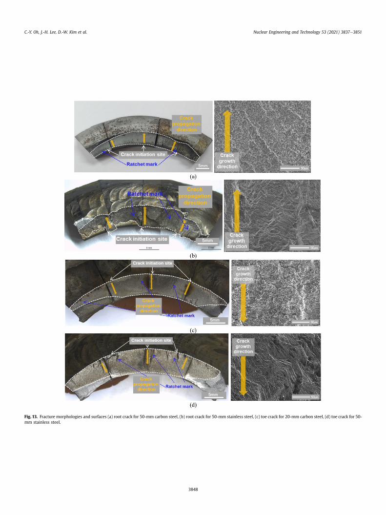
Fig. 13. Fracture morphologies and surfaces (a) root crack for 50-mm carbon steel, (b) root crack for 50-mm stainless steel, (c) toe crack for 20-mm carbon steel, (d) toe crack for 50-mm stainless steel.
C.-Y. Oh, J.-H. Lee, D.-W. Kim et al. Nuclear Engineering and Technology 53 (2021) 3837e3851
3848
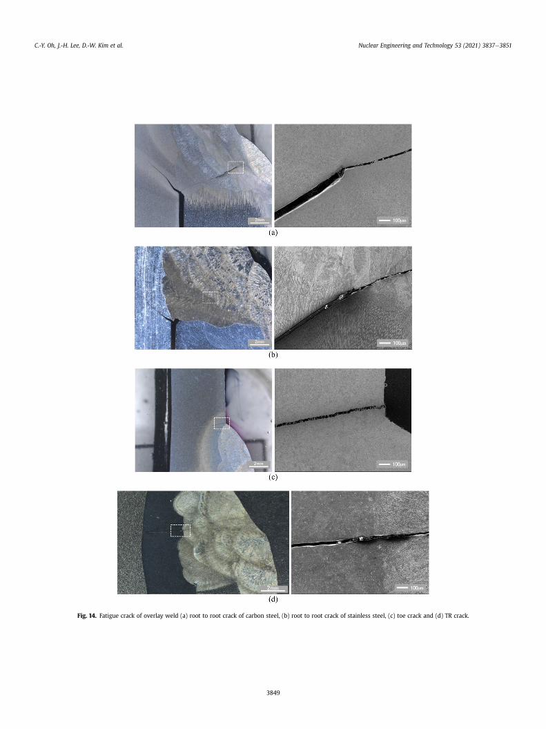
Fig. 14. Fatigue crack of overlay weld (a) root to root crack of carbon steel, (b) root to root crack of stainless steel, (c) toe crack and (d) TR crack.
C.-Y. Oh, J.-H. Lee, D.-W. Kim et al. Nuclear Engineering and Technology 53 (2021) 3837e3851
3849
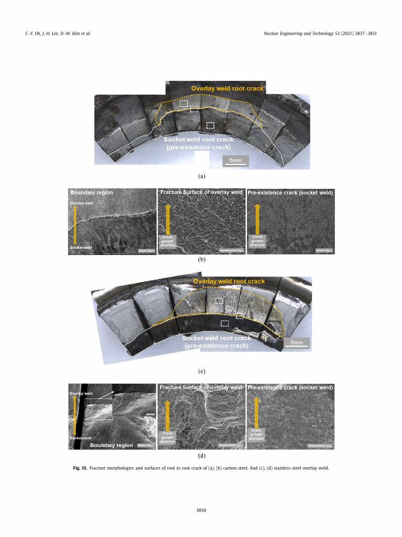
Fig. 15. Fracture morphologies and surfaces of root to root crack of (a), (b) carbon steel. And (c), (d) stainless steel overlay weld.
C.-Y. Oh, J.-H. Lee, D.-W. Kim et al. Nuclear Engineering and Technology 53 (2021) 3837e3851
3850
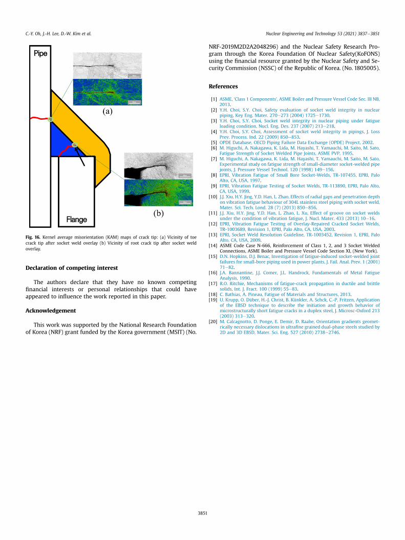
Fig. 16. Kernel average misorientation (KAM) maps of crack tip: (a) Vicinity of toecrack tip after socket weld overlay (b) Vicinity of root crack tip after socket weldoverlay.
C.-Y. Oh, J.-H. Lee, D.-W. Kim et al. Nuclear Engineering and Technology 53 (2021) 3837e3851
Declaration of competing interest
The authors declare that they have no known competingfinancial interests or personal relationships that could haveappeared to influence the work reported in this paper.
Acknowledgement
This work was supported by the National Research Foundationof Korea (NRF) grant funded by the Korea government (MSIT) (No.
3851
NRF-2019M2D2A2048296) and the Nuclear Safety Research Pro-gram through the Korea Foundation Of Nuclear Safety(KoFONS)using the financial resource granted by the Nuclear Safety and Se-curity Commission (NSSC) of the Republic of Korea. (No. 1805005).
References
[1] ASME, ‘Class 1 Components’, ASME Boiler and Pressure Vessel Code Sec. III NB,2013.
[2] Y.H. Choi, S.Y. Choi, Safety evaluation of socket weld integrity in nuclearpiping, Key Eng. Mater. 270e273 (2004) 1725e1730.
[3] Y.H. Choi, S.Y. Choi, Socket weld integrity in nuclear piping under fatigueloading condition, Nucl. Eng. Des. 237 (2007) 213e218.
[4] Y.H. Choi, S.Y. Choi, Assessment of socket weld integrity in pipings, J. LossPrev. Process. Ind. 22 (2009) 850e853.
[5] OPDE Database, OECD Piping Failure Data Exchange (OPDE) Project, 2002.[6] M. Higuchi, A. Nakagawa, K. Lida, M. Hayashi, T. Yamauchi, M. Saito, M. Sato,
Fatigue Strength of Socket Welded Pipe Joints, ASME PVP, 1995.[7] M. Higuchi, A. Nakagawa, K. Lida, M. Hayashi, T. Yamauchi, M. Saito, M. Sato,
Experimental study on fatigue strength of small-diameter socket-welded pipejoints, J. Pressure Vessel Technol. 120 (1998) 149e156.
[8] EPRI, Vibration Fatigue of Small Bore Socket-Welds, TR-107455, EPRI, PaloAlto, CA, USA, 1997.
[9] EPRI, Vibration Fatigue Testing of Socket Welds, TR-113890, EPRI, Palo Alto,CA, USA, 1999.
[10] J.J. Xiu, H.Y. Jing, Y.D. Han, L. Zhao, Effects of radial gaps and penetration depthon vibration fatigue behaviour of 304L stainless steel piping with socket weld,Mater. Sci. Tech. Lond. 28 (7) (2013) 850e856.
[11] J.J. Xiu, H.Y. Jing, Y.D. Han, L. Zhao, L. Xu, Effect of groove on socket weldsunder the condition of vibration fatigue, J. Nucl. Mater. 433 (2013) 10e16.
[12] EPRI, Vibration Fatigue Testing of Overlay-Repaired Cracked Socket Welds,TR-1003689, Revision 1, EPRI, Palo Alto, CA, USA, 2003.
[13] EPRI, Socket Weld Resolution Guideline, TR-1003452, Revision 1, EPRI, PaloAlto, CA, USA, 2009.
[14] ASME Code Case N-666, Reinforcement of Class 1, 2, and 3 Socket WeldedConnections, ASME Boiler and Pressure Vessel Code Section XI, (New York).
[15] D.N. Hopkins, D.J. Benac, Investigation of fatigue-induced socket-welded jointfailures for small-bore piping used in power plants, J. Fail. Anal. Prev. 1 (2001)71e82.
[16] J.A. Bannantine, J.J. Comer, J.L. Handrock, Fundamentals of Metal FatigueAnalysis, 1990.
[17] R.O. Ritchie, Mechanisms of fatigue-crack propagation in ductile and brittlesolids, Int. J. Fract. 100 (1999) 55e83.
[18] C. Bathias, A. Pineau, Fatigue of Materials and Structures, 2013.[19] U. Krupp, O. Düber, H.-J. Christ, B. Künkler, A. Schck, C.-P. Fritzen, Application
of the EBSD technique to describe the initiation and growth behavior ofmicrostructurally short fatigue cracks in a duplex steel, J. Microsc-Oxford 213(2003) 313e320.
[20] M. Calcagnotto, D. Ponge, E. Demir, D. Raabe, Orientation gradients geomet-rically necessary dislocations in ultrafine grained dual-phase steels studied by2D and 3D EBSD, Mater. Sci. Eng. 527 (2010) 2738e2746.