Nuclear Engineering and Technology - KoreaScience
18
Original Article Preliminary study on the thermal-mechanical performance of the U 3 Si 2 /Al dispersion fuel plate under normal conditions Guangliang Yang, Hailong Liao, Tao Ding, Hongli Chen * School of Nuclear Science and Technology, University of Science and Technology of China, Hefei, 230026, China article info Article history: Received 19 October 2020 Received in revised form 7 May 2021 Accepted 11 May 2021 Available online 29 May 2021 Keywords: U 3 Si 2 /Al fuel plate Thermal-mechanical performance Fuel meat swelling Creep abstract The harsh conditions in the reactor affect the thermal and mechanical performance of the fuel plate heavily. Some in-pile behaviors, like fission-induced swelling, can cause a large deformation of fuel plate at very high burnup, which may even disturb the flow of coolant. In this research, the emphasis is put on the thermal expansion, fission-induced swelling, interaction layer (IL) growth, creep of the fuel meat, and plasticity of the cladding for the U 3 Si 2 /Al dispersion fuel plate. A detailed model of the fuel meat swelling is developed. Taking these in-pile behaviors into consideration, the three-dimensional large deformation incremental constitutive relations and stress update algorithms have been developed to study its thermal-mechanical performance under normal conditions using Abaqus. Results have shown that IL can effectively decrease the thermal conductivity of fuel meat. The high Mises stress region mainly locates at the interface between fuel meat and cladding, especially around the side edge of the interface. With irradiation time increasing, the stress in the fuel plate gets larger resulting from the growth of fuel meat swelling but then decreases under the effect of creep deformation. For the cladding, plasticity defor- mation does not occur within the irradiation time. © 2021 Korean Nuclear Society, Published by Elsevier Korea LLC. This is an open access article under the CC BY-NC-ND license (http://creativecommons.org/licenses/by-nc-nd/4.0/). 1. Introduction Plate-type dispersion fuel elements have been widely used in research and test reactors all around the world like CARR [1] and CMRR [2] in China, FRM-II [3] in Germany and JHR [4] in France because of its lower temperature gradient and deeper burnup against traditional rod fuel elements. The main purpose of these research reactors is to generate neutrons as much as possible for use in experiments outside the reactor or to irradiate materials in the reactor. To satisfy the requirement, some high-enriched ura- nium fuels were used in the past. Later, for peaceful use in civil nuclear facilities, many efforts have been made to find high density, low enriched (<20% 235 U) uranium fuels to replace former fuels. The U.S. Department of Energy initiated the Reduced Enrichment Research and Test Reactor (RERTR) program [5e7] in 1978 to get the target. For the time being, the most promising candidate has been proved to be the silicide fuel like U 3 Si 2 in terms of uranium den- sities up to 4.8 g/cm 3 [3,8,9], and because of the best compatibility with matrix Al, the fuel form of U 3 Si 2 particles dispersed in an aluminum matrix (designated as U 3 Si 2 /Al), as shown in Fig. 1 , has been recognized as the best performance fuel for many research and test reactors. Many in-pile and out-of-pile tests have proved that fission- induced swelling, interaction layer (IL) growth, thermal and irra- diation creep have great effects on the thermal-mechanical per- formance of U 3 Si 2 /Al dispersion fuel plates, where lots of researches have been focused on. For a dispersion fuel plate, fuel meat swelling increases due to fission-induced swelling in fuel particles and IL formation, but simultaneously decreases due to the consumption of U 3 Si 2 fuel particles and Al matrix. The fission generated gas atoms are insoluble in fuel particles, then diffuse and cluster to form gas bubbles, which can contribute to the fuel meat swelling, as well as solid fission products. The post-irradiation examinations (PIEs) have indicated that most fission gas bubbles are uniformly distributed in the fuel particles [3, 10, 11], except for some larger ones [8] in high temperature and burnup. Meanwhile, ion irradia- tion and neutron diffraction studies have revealed that the crys- talline U 3 Si 2 transforms to amorphous rapidly under irradiation and stays until a high dose [12], which strongly influences the fission gas bubble mobility and growth. J. Rest et al. [12] developed a model to predict the fission-induced swelling in fuel particles * Corresponding author. E-mail address: [email protected] (H. Chen). Contents lists available at ScienceDirect Nuclear Engineering and Technology journal homepage: www.elsevier.com/locate/net https://doi.org/10.1016/j.net.2021.05.014 1738-5733/© 2021 Korean Nuclear Society, Published by Elsevier Korea LLC. This is an open access article under the CC BY-NC-ND license (http://creativecommons.org/ licenses/by-nc-nd/4.0/). Nuclear Engineering and Technology 53 (2021) 3723e3740
-
Upload
khangminh22 -
Category
Documents
-
view
0 -
download
0
Transcript of Nuclear Engineering and Technology - KoreaScience

lable at ScienceDirect
Nuclear Engineering and Technology 53 (2021) 3723e3740
Contents lists avai
Nuclear Engineering and Technology
journal homepage: www.elsevier .com/locate/net
Original Article
Preliminary study on the thermal-mechanical performance of theU3Si2/Al dispersion fuel plate under normal conditions
Guangliang Yang, Hailong Liao, Tao Ding, Hongli Chen*
School of Nuclear Science and Technology, University of Science and Technology of China, Hefei, 230026, China
a r t i c l e i n f o
Article history:Received 19 October 2020Received in revised form7 May 2021Accepted 11 May 2021Available online 29 May 2021
Keywords:U3Si2/Al fuel plateThermal-mechanical performanceFuel meat swellingCreep
* Corresponding author.E-mail address: [email protected] (H. Chen).
https://doi.org/10.1016/j.net.2021.05.0141738-5733/© 2021 Korean Nuclear Society, Publishedlicenses/by-nc-nd/4.0/).
a b s t r a c t
The harsh conditions in the reactor affect the thermal and mechanical performance of the fuel plateheavily. Some in-pile behaviors, like fission-induced swelling, can cause a large deformation of fuel plateat very high burnup, which may even disturb the flow of coolant. In this research, the emphasis is put onthe thermal expansion, fission-induced swelling, interaction layer (IL) growth, creep of the fuel meat, andplasticity of the cladding for the U3Si2/Al dispersion fuel plate. A detailed model of the fuel meat swellingis developed. Taking these in-pile behaviors into consideration, the three-dimensional large deformationincremental constitutive relations and stress update algorithms have been developed to study itsthermal-mechanical performance under normal conditions using Abaqus. Results have shown that IL caneffectively decrease the thermal conductivity of fuel meat. The high Mises stress region mainly locates atthe interface between fuel meat and cladding, especially around the side edge of the interface. Withirradiation time increasing, the stress in the fuel plate gets larger resulting from the growth of fuel meatswelling but then decreases under the effect of creep deformation. For the cladding, plasticity defor-mation does not occur within the irradiation time.© 2021 Korean Nuclear Society, Published by Elsevier Korea LLC. This is an open access article under the
CC BY-NC-ND license (http://creativecommons.org/licenses/by-nc-nd/4.0/).
1. Introduction
Plate-type dispersion fuel elements have been widely used inresearch and test reactors all around the world like CARR [1] andCMRR [2] in China, FRM-II [3] in Germany and JHR [4] in Francebecause of its lower temperature gradient and deeper burnupagainst traditional rod fuel elements. The main purpose of theseresearch reactors is to generate neutrons as much as possible foruse in experiments outside the reactor or to irradiate materials inthe reactor. To satisfy the requirement, some high-enriched ura-nium fuels were used in the past. Later, for peaceful use in civilnuclear facilities, many efforts have beenmade to find high density,low enriched (<20% 235U) uranium fuels to replace former fuels.The U.S. Department of Energy initiated the Reduced EnrichmentResearch and Test Reactor (RERTR) program [5e7] in 1978 to get thetarget.
For the time being, the most promising candidate has beenproved to be the silicide fuel like U3Si2 in terms of uranium den-sities up to 4.8 g/cm3 [3,8,9], and because of the best compatibility
by Elsevier Korea LLC. This is an
with matrix Al, the fuel form of U3Si2 particles dispersed in analuminum matrix (designated as U3Si2/Al), as shown in Fig. 1, hasbeen recognized as the best performance fuel for many researchand test reactors.
Many in-pile and out-of-pile tests have proved that fission-induced swelling, interaction layer (IL) growth, thermal and irra-diation creep have great effects on the thermal-mechanical per-formance of U3Si2/Al dispersion fuel plates, where lots of researcheshave been focused on. For a dispersion fuel plate, fuel meat swellingincreases due to fission-induced swelling in fuel particles and ILformation, but simultaneously decreases due to the consumption ofU3Si2 fuel particles and Al matrix. The fission generated gas atomsare insoluble in fuel particles, then diffuse and cluster to form gasbubbles, which can contribute to the fuel meat swelling, as well assolid fission products. The post-irradiation examinations (PIEs)have indicated that most fission gas bubbles are uniformlydistributed in the fuel particles [3,10,11], except for some largerones [8] in high temperature and burnup. Meanwhile, ion irradia-tion and neutron diffraction studies have revealed that the crys-talline U3Si2 transforms to amorphous rapidly under irradiationand stays until a high dose [12], which strongly influences thefission gas bubble mobility and growth. J. Rest et al. [12] developeda model to predict the fission-induced swelling in fuel particles
open access article under the CC BY-NC-ND license (http://creativecommons.org/

Nomenclature
�DVV
�f
Fuel particle swelling�DVV
�s
Fission solid swelling�DVV
�g
Fission gas swelling�DVV
�g;before
Fission gas swelling before the knee point�DVV
�g;after
Fission gas swelling after the knee point
bs Fractional swelling due to solid fission products perunit fission density
fd Fission densityRds Ratio of the average diameter of a bubble to the
average inter-bubble spacingc Fraction of fission gas generated that exists in
bubblesb0 Initial gas atom resolution rateD0 Trap free diffusion of gas atomIðrIÞ Average number of sphere bubbles intersect with
other bubbles with radius rIrI Radius at IðrIÞ ¼ 1, smallest bubble within the tail
regionRp Radius at peak of bubble within the tail regionRk Radius at kneeN1 Bell shaped distribution of small diameter bubblesN2 Bell shaped distribution of large diameter bubblesck Chi at knee_f Fission rateb Gas atoms produce per fissionm0 Bubble distributionT Temperaturet Timef Experimentally determined time constant, 8� 10�8
g Constant, 0.7Y IL thicknessR Gas constantVf VAl, VIL Volume of U3Si2 particle, Al Matrix, and ILVh, Vg Overlapping volumes with neighboring particlesndp, nf , nIL, nm Volume fraction of dispersed phase, U3Si2 particle,
IL and Al matrix in the fuel meatr Radius of a U3Si2 particlea Energy released per fissionRd Radius of the dispersed particled Distance between the surfaces of two neighboring
particlesh, g: Height of different overlapping sphereVcf V
cAl Consumed volume of U3Si2 and Al Matrix per fuel
particlerf , rIL Density of U3Si2, ILMf , MIL Molecular weights of U3Si2 particle and ILx Atomic ratio of Al to (U, Si) in the ILðDV=VÞIL Fission-induced swelling of ILVf ;0, VAl;0 As-fabricated volume of U3Si2 particle and Al matrix
nf ;0 As-fabricated fuel volume fraction in the fuel meatðDV=VÞm Fuel meat swellingANH Material constantDL Exponential equation for lattice diffusionb Burger's vectorkb Boltzmann constantdg Average grain size_εNH Strain rate for Nabarro Herring creepx, y, z: Coordinate in x, y and z directionS Volumetric heat sourcexfactor , zfactor Non-uniform factor in width and longitudinal
directionxdand zd Normalized distance in x and z directionl, G Lame constantsDs Stress incrementsDεeij Elastic logarithmic strain increments
Dεtotalij , Dεthij , Dεswij , Dεcrij , Dε
pij Increment of total strain, thermal
expansion strain, swelling strain,creep strain and plasticity strain
dεcrij Small creep strain increment components
dεcr Small increment of equivalent creep strainDεcr Equivalent creep strain incrementDεcrij Creep strain increment
stij Cauchy stress at t
stþDtij Cauchy stress at t þ Dt
se Von Mises stressstrij Trial Cauchy stress
sij Deviatoric stress
strij Trial deviatoric stresses
stij Deviatoric stresses at t
stþDtij Deviatoric stresses at t þ Dt
ste Von Mises stress at t
stþDte Von Mises stress at t þ Dt
stre Trial von Mises stressdεpij Small plastic strain increment components
dεp Small increment of equivalent plastic strainDεp Equivalent plasticity strain incrementhf Heat transfer coefficientTc Temperature of coolantFðeÞ Function of the eccentricity of the dispersed fuel
phasevdp=IL Partial volume fraction ratio of the fuel particle to the
summation of volume fractions of the fuel particleand IL
le, lf , lIL, lm, ldp Thermal conductivity of the fuel meat, fuelparticle, IL, Al matrix and dispersed particle
Ke, Kf , KIL Km, Kdp Bulk modulus of the fuel meat, fuel particle, IL,Al matrix and dispersed particle
me, mf , mIL mm, mdp Shear modulus of the fuel meat, fuel particle,IL, Al matrix and dispersed particle
ae, af , aIL, am Thermal expansion coefficient of the fuel meat,fuel particle, IL and Al matrix
G. Yang, H. Liao, T. Ding et al. Nuclear Engineering and Technology 53 (2021) 3723e3740
based on the rate theory considering the amorphous characteristicof U3Si2. Besides the fission-induced swelling, out-of-pile tests alsoshowed that the IL [14], a material named U(Al, Si)3 with a structure
3724
type similar to that of UAl3, is formed between fuel particles andmatrix by interdiffusion. It may change the volume of the fuel meatby consuming the fuel particles and matrix and the thermal
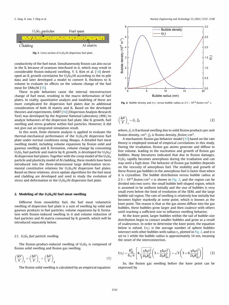
Fig. 1. Cross-section of U3Si2/Al dispersion fuel plate.
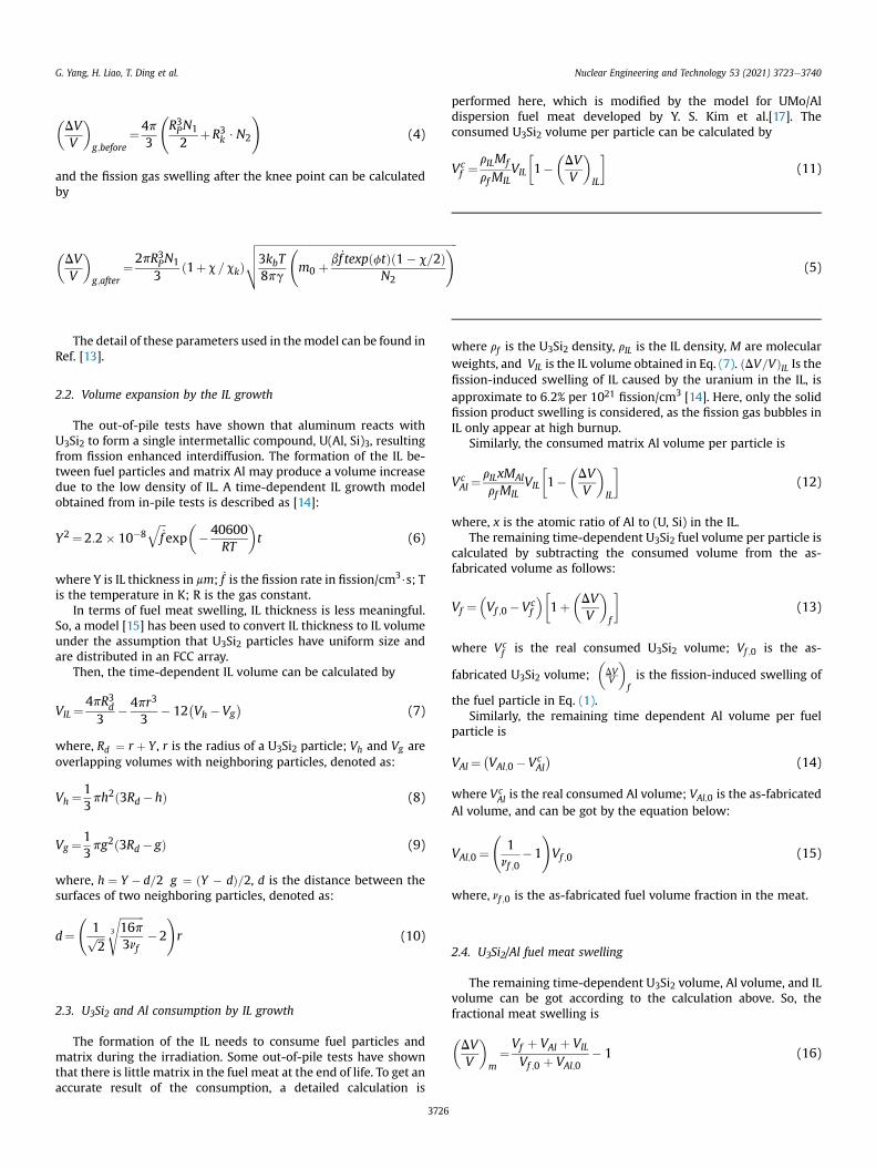
Fig. 2. Bubble density and IðrIÞ versus bubble radius at 2:5� 1014 fission=cm3$s.
G. Yang, H. Liao, T. Ding et al. Nuclear Engineering and Technology 53 (2021) 3723e3740
conductivity of the fuel meat. Simultaneously fission can also occurin the IL because of uranium interfused in it, which may result inconsiderable fission-induced swelling. Y. S. Kim et al. [14] devel-oped an IL growth correlation for U3Si2/Al according to the in-piledata and later developed a model to convert IL thickness to ILvolume to evaluate its effects on the volume change of the fuelmeat for UMo/Al [15].
These in-pile behaviors cause the internal microstructurechange of fuel meat, resulting in the macro deformation of fuelplates. In reality, quantitative analysis and modeling of these aremore complicated for dispersion fuel plates due to additionalconsideration of both Al matrix and IL. Based on the developedtheories and experiments, DART [16] (Dispersion Analysis ResearchTool) was developed by the Argonne National Laboratory (ANL) toanalyze behaviors of the dispersion fuel plate, like IL growth, fuelswelling and stress gradient within fuel particles. However, it didnot give out an integrated simulation result.
In this work, finite element analysis is applied to evaluate thethermal-mechanical performance of the U3Si2/Al dispersion fuelplate under normal conditions using Abaqus. A detailed fuel meatswelling model, including volume expansion by fission solid andgaseous swelling and IL formation, volume change by consumingU3Si2 fuel particle and matrix by IL growth, is developed for U3Si2/Al dispersion fuel plates. Together with the creepmodel of the U3Si2particle and plasticitymodel of Al cladding, thesemodels have beenintroduced into the three-dimensional large deformation incre-mental constitutive relations for U3Si2/Al dispersion fuel plates.Based on these relations, stress update algorithms for the fuel meatand cladding are developed and used to study the evolution ofstress and deformation in the U3Si2/Al dispersion fuel plate.
2. Modeling of the U3Si2/Al fuel meat swelling
Different from monolithic fuel, the fuel meat volumetricswelling of dispersion fuel plate is a sum of swelling by solid andgaseous products in fuel particles, volume expansion by IL forma-tion with fission-induced swelling in it and volume reduction offuel particles and Al matrix consumed by IL growth, which will beintroduced separately below.
2.1. U3Si2 fuel particle swelling
The fission-product-induced swelling of U3Si2 is composed offission solid swelling and fission gas swelling.
�DVV
�f¼�DVV
�sþ�DVV
�g
(1)
The fission solid swelling is calculated by an empirical equation:
3725
�DVV
�s¼ bs$fd (2)
where, bs is fractional swelling due to solid fission products per unitfission density, cm3; fd is fission density, fission=cm3.
A mechanistic fission gas behavior model [13] based on the ratetheory is employed instead of empirical correlations in this study.During the irradiation, fission gas atoms generate and diffuse tofree volume, leading to the nucleation and growth of fission gasbubbles. Many literatures indicated that due to fission damages,U3Si2 rapidly becomes amorphous during the irradiation and canstay until a high dose. The behavior of fission gas bubbles dependson the viscosity of amorphous fuel. The mobility and growth ofthese fission gas bubbles in the amorphous fuel is faster thanwhenit is crystalline. The bubble distribution versus bubble radius at2:5� 1014 fission=cm3$s is shown in Fig. 2, and the region can bedivided into two sorts: the small bubble bell-shaped region, whichis assumed to be uniform initially and the size of bubbles is verysmall even below the limit of resolution of the SEM, and the largebubble tail region. The rate of swelling is relatively low initially butbecomes higher markedly at some point, which is known as theknee point. The reason is that as the gas atoms diffuse into the gasbubbles, these bubbles grow larger and then coalesce with othersuntil reaching a sufficient size to influence swelling behavior.
At the knee point, larger bubbles within the tail of bubble-sizedistribution begin to contact smaller bubbles and grow as a resultof coalescence. In order to determine the knee point, the equationbelow is solved. IðrIÞ is the average number of sphere bubblesintersect with other bubbles with radius rI , plotted in Fig. 2, and it isset to 1 while the bubble radius is approximately 14 nm, meaningthe onset of the interconnection.
IðrIÞ¼R3ds6ffiffiffip
p244
ffiffiffiffiffiffiffiffiffiffiffiffifficb0r2ID0R
3ds
vuut 3þcb0r2I
D0R3ds
!þ ffiffiffi
pp 3þ6
cb0r2ID0R3ds
!35 (3)
So, the fission gas swelling before the knee point can beexpressed by
G. Yang, H. Liao, T. Ding et al. Nuclear Engineering and Technology 53 (2021) 3723e3740
�DVV
�g;before
¼4p3
R3PN1
2þR3k $N2
!(4)
and the fission gas swelling after the knee point can be calculatedby
�DVV
�g;after
¼2pR3PN1
3ð1þc =ckÞ
ffiffiffiffiffiffiffiffiffiffiffiffiffiffiffiffiffiffiffiffiffiffiffiffiffiffiffiffiffiffiffiffiffiffiffiffiffiffiffiffiffiffiffiffiffiffiffiffiffiffiffiffiffiffiffiffiffiffiffiffiffiffiffiffiffiffiffiffiffiffiffiffiffiffi3kbT8pg
m0 þ
b _f texpðftÞð1� c=2ÞN2
!vuut (5)
The detail of these parameters used in themodel can be found inRef. [13].
2.2. Volume expansion by the IL growth
The out-of-pile tests have shown that aluminum reacts withU3Si2 to form a single intermetallic compound, U(Al, Si)3, resultingfrom fission enhanced interdiffusion. The formation of the IL be-tween fuel particles and matrix Al may produce a volume increasedue to the low density of IL. A time-dependent IL growth modelobtained from in-pile tests is described as [14]:
Y2 ¼2:2� 10�8ffiffiffi_f
qexp
��40600
RT
�t (6)
where Y is IL thickness in mm; _f is the fission rate in fission/cm3$s; Tis the temperature in K; R is the gas constant.
In terms of fuel meat swelling, IL thickness is less meaningful.So, a model [15] has been used to convert IL thickness to IL volumeunder the assumption that U3Si2 particles have uniform size andare distributed in an FCC array.
Then, the time-dependent IL volume can be calculated by
VIL ¼4pR3d3
� 4pr3
3� 12
�Vh�Vg
�(7)
where, Rd ¼ r þ Y , r is the radius of a U3Si2 particle; Vh and Vg areoverlapping volumes with neighboring particles, denoted as:
Vh ¼13ph2ð3Rd �hÞ (8)
Vg ¼13pg2ð3Rd� gÞ (9)
where, h ¼ Y � d=2 g ¼ ðY � dÞ=2, d is the distance between thesurfaces of two neighboring particles, denoted as:
d¼
1ffiffiffi2
pffiffiffiffiffiffiffiffiffi16p3nf
3
s�2
!r (10)
2.3. U3Si2 and Al consumption by IL growth
The formation of the IL needs to consume fuel particles andmatrix during the irradiation. Some out-of-pile tests have shownthat there is little matrix in the fuel meat at the end of life. To get anaccurate result of the consumption, a detailed calculation is
3726
performed here, which is modified by the model for UMo/Aldispersion fuel meat developed by Y. S. Kim et al.[17]. Theconsumed U3Si2 volume per particle can be calculated by
Vcf ¼
rILMf
rf MILVIL
�1�
�DVV
�IL
�(11)
where rf is the U3Si2 density, rIL is the IL density, M are molecularweights, and VIL is the IL volume obtained in Eq. (7). ðDV=VÞIL Is thefission-induced swelling of IL caused by the uranium in the IL, isapproximate to 6:2% per 1021 fission/cm3 [14]. Here, only the solidfission product swelling is considered, as the fission gas bubbles inIL only appear at high burnup.
Similarly, the consumed matrix Al volume per particle is
VcAl ¼
rILxMAlrf MIL
VIL
�1�
�DVV
�IL
�(12)
where, x is the atomic ratio of Al to (U, Si) in the IL.The remaining time-dependent U3Si2 fuel volume per particle is
calculated by subtracting the consumed volume from the as-fabricated volume as follows:
Vf ¼Vf ;0 �Vc
f
�1þ
�DVV
�f
�(13)
where Vcf is the real consumed U3Si2 volume; Vf ;0 is the as-
fabricated U3Si2 volume;�DVV
�fis the fission-induced swelling of
the fuel particle in Eq. (1).Similarly, the remaining time dependent Al volume per fuel
particle is
VAl ¼�VAl;0 �Vc
Al
�(14)
where VcAl is the real consumed Al volume; VAl;0 is the as-fabricated
Al volume, and can be got by the equation below:
VAl;0 ¼
1nf ;0
�1
!Vf ;0 (15)
where, nf ;0 is the as-fabricated fuel volume fraction in the meat.
2.4. U3Si2/Al fuel meat swelling
The remaining time-dependent U3Si2 volume, Al volume, and ILvolume can be got according to the calculation above. So, thefractional meat swelling is
�DVV
�m¼Vf þ VAl þ VIL
Vf ;0 þ VAl;0� 1 (16)

G. Yang, H. Liao, T. Ding et al. Nuclear Engineering and Technology 53 (2021) 3723e3740
3. Creep model of U3Si2
Mass transfer of fuel plates has been observed in some tests,which is attributed to the stress-induced by fuel meat swelling, andthe stresses can be mitigated by the creep of a continuous phase.However, it is complicated to quantitative analysis and modelingfor this phenomenon in dispersion fuel plates when consideringU3Si2 fuel particles, Al matrix, and IL. So, for simplicity, only thecreep deformation of U3Si2 is considered in this research.
The creep of U3Si2 in reactors can be divided into two parts:athermal irradiation-induced creep and thermal creep. The tworegimes are distinguished by a temperature of 0:45Tmelt , namely872 K. The reason is that Uranium Carbide (UC), whose transitiontemperature between athermal and thermal creep was 0.45 timesits melting temperature, has similar strong bonding characteristicsand behaviors to U3Si2. Athermal irradiation-induced creep,causing the creation of point defects in the lattice, is the creepmechanism below 872 K, while thermal creep dominates theoverall creep strain above 872 K.
In research or test reactors, the temperature of the fuel plate isalways lower than the 0.45 times its melting temperature. So,athermal irradiation-induced creep of U3Si2 is only considered inthis research. The irradiation induced creep strain is usually afunction of flux and a constant. However, due to the lack of irra-diation data, this irradiation strain rate will be approximated by theNabarro-Herring lattice creep mechanism [18]. The strain rate forNabarro-Herring creep is described as:
_εNH ¼ dεcr
dt¼ ANHDLb3s
kbTdg2 (17)
DL ¼5:26� 10�11e�2:28�10�19
R�T (18)
where ANH is a material constant, 12.5, DL is the exponentialequation for lattice diffusion, b is the burger's vector, 0.56 nm, s isthe von Mises stress, kb is the Boltzmann constant, and dg is theaverage grain size, 20 mm. In Nabarro-Herring creep, DL is anexponential term for lattice diffusion, which is actually that forirradiation diffusion in this case, R is the gas constant, T is thetemperature. Because irradiation induced creep is athermal, thevalue of T in the denominator of Eqs. (17) and (18) is held constant
Fig. 3. Fission rate distribution.
3727
at 332.5 K, which is the average temperature of the fuel meat in thissimulation. This ensures that the creep strain rate due to latticecreep remains the same across all temperatures below the transi-tion point from irradiation to thermal creep.
4. Governing equations
4.1. Heat conduction equation
The temperature is important for the performance of the fuelplate, which has a great influence on in-pile behaviors andmaterialproperties. Abaqus [19] offers the heat transfer module to calculatethe temperature distribution in the dispersion fuel plate. Thesteady heat conduction equation in three dimensions is given by:
k
v2Tvx
þ v2Tvy
þ v2Tvz
!þ S¼0 (19)
where, S is the volumetric heat source, and can be calculated basedon fission rate:
S¼ nf ;0$_f $a$xfactor$zfactor (20)
where, nf ;0 is the as-fabricated particle volume fraction in the fuel
meat, _f is the fission rate (fission/cm3$s) and set as2:5� 1014 fission=cm3$s in this study, a is the energy released perfission (J/fission), commonly taken to be 3:28451� 10�11J/fission.Fig. 3 shows the fission rate distribution factor for the fuel plate.xfactor and zfactor are the factor in width and length directionrespectively.
xfactor ¼7:9418x4d � 0:0741x3d þ 0:182x2d þ 0:0163xd þ 0:9547
(21)
zfactor ¼ cosðpzdÞ (22)
where the variables xd and zd represent the normalized distance inx and z direction respectively.
4.2. The three-dimensional stress-update algorithms
The dispersion fuel plate in reactor will be irradiated by highneutron flux for a long time. Therefore, the entire period is dividedinto several steps. Taking the in-pile behaviors into account, thethree-dimensional stress update algorithmswere developed for thedispersion fuel plate based on the incremental constitutive relationbelow [20]:
Dsij ¼ stþDtij � stij ¼ 2GDεeij þ lDεekkdij (23)
where Ds represents the stress increments; Dεeij depicts the elastic
logarithmic strain increments instead of engineering strain for ac-curacy; l and G are the Lame constants.
4.2.1. The three-dimensional stress-update algorithm for theequivalent fuel meat
The total strain of the fuel meat is composed of the elastic strain,thermal expansion strain, swelling strain, and creep strain. Then,the local elastic strain increment Dεeij can be written as:
Dεeij ¼Dεtotalij � Dεthij � Dεswij � Dεcrij (24)

G. Yang, H. Liao, T. Ding et al. Nuclear Engineering and Technology 53 (2021) 3723e3740
where Dεtotalij is the total strain increment, and Dεthij ; Dεswij ; Dεcrij
separately represents the increment of the thermal expansionstrain, swelling strain and creep strain at the integration point, andcan be written as:
Dεthij ¼ ½lnð1þaTþDT ðT þDT � T0ÞÞ� lnð1þaTðT � T0ÞÞ�
dij ¼ ln1þ aTþDT ðT þ DT � T0Þ
1þ aT ðT � T0Þdij
(25)
Dεswij ¼13½lnð1þ swðT þDT ; tþDtÞÞ� lnð1þ swðT ; tÞÞ�
dij ¼13ln
1þ swðT þ DT ; t þ DtÞ1þ swðT ; tÞ dij
(26)
where a is the equivalent thermal expansion coefficient; T0 is thereference temperature in K. Both thermal and swelling strain ten-sors are spherical ones which only result in volumetric variations inthe fuel meat.
The small creep strain increment components dεcrij can be
derived out similar as the plastic constitutive theory as follows:
dεcrij ¼3sij2se
dεcr (27)
where dεcr represents a small increment of equivalent creep strain.
sij ¼ sij � ðskk =3Þdij is the deviatoric stresses, and se ¼ffiffiffiffiffiffiffiffiffiffiffiffiffiffiffiffiffiffiffiffiffið3=2Þsijsij
qis the von Mises stress. Obviously, the creep strain tensor is adeviatoric one with ε
crkk ¼ 0.
The creep strain increment is calculated by trapezoidal inte-gration as:
Dεcrij ¼3stþDtij þ stij
2�stþDte þ ste
�Dεcr (28)
The equivalent creep strain increment Dεcr in a typical timeincrement can be derived using the time hardening theory andmid-value integration.
Dεcr ¼ANHDLb3
kTd2$12�stþDte þst
e�$Dt (29)
Plugging Eq. (29) into Eq. (28), we can get
Dεcrij ¼ANHDLb3
kTd2$34
stþDtij þ stij
$Dt (30)
The Cauchy stress stþDtij can be obtained as:
stþDtij ¼strij � 2GDεcrij ¼ strij �
32GANHDLb3
kTd2$stþDtij þ stij
$Dt (31)
With the assumption Dεcrij ¼ 0, strij is derived as:
strij ¼ stij þ2G�Dεtotalij �Dεthij �Dεswij
þ lDεtotalkk �Dεthkk �Dεswkk
dij (32)
Then, stþDtij can be denoted as:
3728
stþDtij ¼
strij � 32Gs
tijANHDLb3
kTd2 Dt
1þ ð3=2ÞGANHDLb3
kTd2 Dt(33)
where stþDtij ¼ stþDt
ij � 13s
tþDtkk dij; strij ¼ strij � 1
3strkkdij;s
tþDtij ¼ strkk.
Finally, the Cauchy stress stþDtij can be updated as:
stþDtij ¼ stþDt
ij þ strkk3dij (34)
4.2.2. The three-dimensional stress-update algorithm for thecladding
Due to the lack of irradiation data for Al cladding, the irradiationbehavior of the cladding was ignored in this simulation. The totalstrain of the cladding can be divided into the elastic strain andplasticity strain. The implicit integration, named the radial returnmethod [21], is used to calculate plasticity strain. The elastic strainfor the cladding can be denoted as:
Dεeij ¼Dεtotalij � Dεpij (35)
where Dεtotalij ;Dεeij;Dεpij represents the total strain increment, elastic
strain increment, and plasticity strain increment, respectively.First, assuming that there is no plastic strain taking place during
the time step, which is Dεpij ¼ 0. Then, we can get the trial stress strijas follows:
strij ¼ stij þ 2G� Dεtotalij þ lDεtotalkk dij (36)
Next, the trial von Mises stress can be calculated by stre ¼ffiffiffiffiffiffiffiffiffiffiffiffiffiffiffiffiffiffiffiffiffiffið3=2Þstrij strij
q, strij ¼ strij � ð1 =3Þstrkkdij. At the same time, the yield
stress sye can be got from the plasticity model with the plastic strainεtp at time t. If stre � ð1þ1�10�6Þsye , the plastic deformation hasoccurred in this time step. Otherwise, the trial stress is the real oneand the stress update is accomplished.
If plastic strain occurred in the cladding, the trial stress strij is
outside of the yield surface. According to the plastic constitutivetheory, small plastic strain increment components dεpij can be
derived as:
dεpij ¼3sij2se
dεp (37)
Backward Euler Integration of Eq. (37) yields:
Dεpij ¼3stþDt
ij
2stþDte
Dεp (38)
Considering the plastic strain increment, stþDtij at time t þ Dt can
be expressed as:
stþDtij ¼strij � 2GDεpij ¼ strij � G
3stþDtij
stþDte
Dεp (39)
As we known, the plastic strain tensor is a deviator one, which
means Dεpkk ¼ 0. So, stþDtkk ¼ strkk, and then the deviatoric stress can
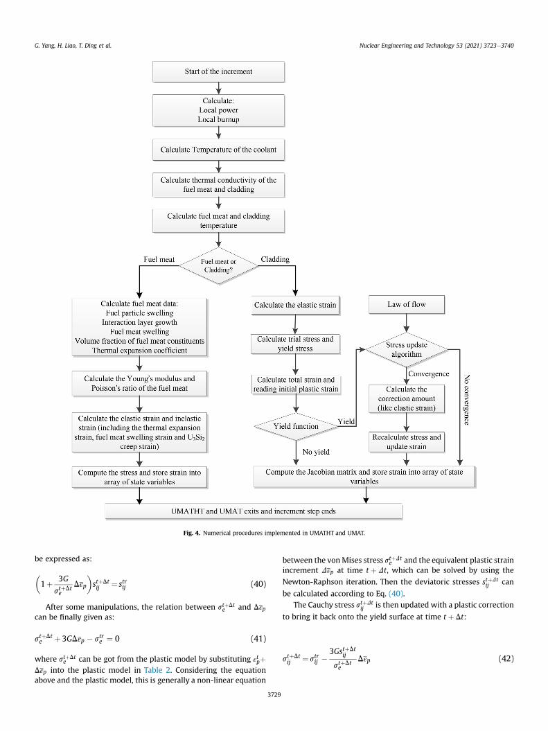
Fig. 4. Numerical procedures implemented in UMATHT and UMAT.
G. Yang, H. Liao, T. Ding et al. Nuclear Engineering and Technology 53 (2021) 3723e3740
be expressed as:
�1þ 3G
stþDte
Dεp
�stþDtij ¼ strij (40)
After some manipulations, the relation between stþDte and Dεp
can be finally given as:
stþDte þ3GDεp � stre ¼ 0 (41)
where stþDte can be got from the plastic model by substituting ε
tpþ
Dεp into the plastic model in Table 2. Considering the equationabove and the plastic model, this is generally a non-linear equation
3729
between the vonMises stress stþDte and the equivalent plastic strain
increment Dεp at time t þ Dt, which can be solved by using the
Newton-Raphson iteration. Then the deviatoric stresses stþDtij can
be calculated according to Eq. (40).The Cauchy stress stþDt
ij is then updated with a plastic correction
to bring it back onto the yield surface at time t þ Dt:
stþDtij ¼strij �
3GstþDtij
stþDte
Dεp (42)

Fig. 5. Schematic and mesh of the dispersion fuel plate with data boundary conditions and output paths.
Table 1The fuel properties of the proposed U3Si2/Al dispersion fuel plate.
Fuel properties U3Si2
Meat density (g/cm3) 7.14Dispersed phase density (g/cm3) 12.2U in dispersed phase (wt%) 92.50U density in dispersed phase (g/cm3) 11.30U density in the meat (g/cm3) 4.42Volume fraction of dispersed phase (%) 0.392
G. Yang, H. Liao, T. Ding et al. Nuclear Engineering and Technology 53 (2021) 3723e3740
5. Finite element modeling
Abaqus [19], a finite element analysis software, can solve a lot ofcomplex nonlinear problems. It provides some flexible user sub-routines, like UMAT and UMATHT to define the mechanical andthermal constitutive equations of different materials. With thisfeature, the three-dimensional stress-update algorithms for thefuel meat and cladding, considering the material properties and in-pile behaviors, can be programmed into the UMAT and UMATHT toevaluate the thermal-mechanical performance of U3Si2/Al disper-sion fuel plate. A flowchart describing the general simulation isshown in Fig. 4.
5.1. Geometry
The U3Si2/Al dispersion fuel plate dimensions are 100 mm inlength, 25mm inwidth, and 1.4 mm in thickness with the fuel meatdimensions are 81.3 mm in length and 18.5 mm in width and0.64 mm in thickness, which is a sub-size version. According to thesymmetry, 1/4 of the sub-size fuel plate was established in order toreduce calculation costs. The reduced integration element C3D8RTis used to generate a grid, which is refined in the contact regionbetween the fuel meat and cladding. The schematic and mesh ofthe fuel plate with data output paths and boundary conditions usedin this research are shown in Fig. 5.
5.2. Boundary conditions
� Mechanical boundary conditions
3730
The upper surface and transverse midplane are set as a sym-metrical boundary;
The side surface is fixed to restrain the movement of the plate;The other surfaces are set as free surfaces, as shown in Fig. 5.
� Thermal boundary conditions
The convection heat transfer boundary is used in the lowersurface of the model shown in Fig. 5.
�kvTvn
¼ hf ðT � TcÞ (43)
Tc ¼0:18*ð50þ zÞ þ 308 (44)
where, k is thermal conductivity; Tc is the temperature of coolantand increases linearly with the axial height to evaluate the influ-ence to the thermal-mechanical performance of the fuel plate; z isthe z-coordinate in mm; hf is heat transfer coefficient between the

Table 2Material properties of U3Si2, IL and Aluminum.
U3Si2 ILa Aluminum
Thermal conductivity (W/m$K) 7:98þ 0:0051� ðT �273:15Þ [28] 5.5 [32] �1:77� 10�4T2 þ 0:19T þ 138:55 [33]Young's modulus (GPa) 120 [28] 134 [30] 69 [35]Poisson's ratio 0.177 [29] 0.2 [30] 0.33 [35]Thermal expansion coefficient (1/K) 15.0e-6 [28] 11.5e-6 [31] ð0:9T þ2018Þ � 10�8 [33]Plasticity model (MPa) / / s ¼ 569:6ε0:13 [34]
T represents the temperature in K.a Assumed to be the same as that of UAl3.
G. Yang, H. Liao, T. Ding et al. Nuclear Engineering and Technology 53 (2021) 3723e3740
plate and coolant, which is calculated by the Dittus-Boelter (D-B)correlation with the inlet velocity equals 7.5 m/s. Some experi-ments have proven that the D-B correlation is available for bothupward and downward flow in narrow-gap channels with a Rey-nolds number higher than 104 [22].
The other surfaces are set as an adiabatic boundary condition, asshown in Fig. 5.
5.3. Material properties
For the U3Si2/Al dispersion fuel plate, the fuel meat, withfissionable U3Si2 fuel particles dispersedly distributed on an inertmatrix Al, and cladding (Al) are metallurgically combined. Thedetailed fuel properties of the U3Si2/Al dispersion fuel plate arelisted in Table 1. Meanwhile, fuel meat can be viewed as particlecomposite material. All local properties in the fuel meat aredifferent as burnup increases, taking account of changes occurredin fuel meat by IL growth and fuel particle/Al consumption.
The effective fuel meat thermal conductivity is calculated basedon the Hsu model [23], given as:
f1� FðeÞgl2e þnldp
hFðeÞ� ndp
iþ lm½FðeÞ� nm�
ole � ldplmFðeÞ¼0
(45)
where, l is the thermal conductivity, n is the volume fraction, FðeÞ isa function of the eccentricity of the dispersed fuel phase and isdesigned to take into account the shape and orientation of thephase, and the subscripts e;m; dp represent the fuel meat, Al ma-trix, and dispersed particle (the fuel particle coated with IL),respectively.
The effective thermal conductivity of the dispersed particle iscalculated by the equation summarized by Badrinarayan andBarlow [24], given as:
ldp¼Rd��
2Rda
�ln�
ðaRdþbÞðaðRd�rÞþbÞ
�þ�
ba2
�ln�
ðaRdþbÞðaðRd�rÞþbÞ
�þ�Rd�rlIL
��ra
�(46)
where a ¼ � lf , b ¼ 2ðRd � rÞlIL þ 2rlf . In equation, Rd is the sumof fuel particle radius and IL thickness, r is the fuel particle radius, lfis the fuel particle thermal conductivity, lIL is the interaction layerthermal conductivity.
In order to calculate the equivalent Young's modulus and Pois-son's ratio of the fuel meat, the mechanical moduli of the dispersedparticle should be first calculated. The differential effectivemediumtheory, developed by Garboczi and Berryman [25], was employedfor it.
The bulk modulus of the dispersed particle is given by using thegeneralized self-consistent method [26] as follows:
3731
Kdp ¼KIL þvdp=IL
Kf � KIL
�1 þ1� vdp=IL
�KIL þ 4
3mIL
��1 (47)
where Kdp, Kf and KIL are the bulk moduli of the dispersed particle,the fuel particle and IL respectively, and vdp=IL is the partial volumefraction ratio of the fuel particle to the summation of volumefractions of the fuel particle and IL, given as:
vdp=IL ¼ vdp
.vdp þ vIL
The shear modulus of the dispersed particle is given by solving
the quadratic equation which is given as follows:
C1
�mdpmIL
�2
þ2C2
�mdpmIL
�þ C3 ¼ 0 (48)
where mdp and mIL are the shear modulus of the dispersed particleand IL respectively. And C1 C2, and C3 are constant which are pre-sumed by the radius of the U3Si2, IL thickness, and Poisson's ratio ofU3Si2, IL and Al matrix. More details concerning the formulas ofthese constants can be found in Ref. [25].
The bounds model developed by Hashin and Shtrikman [27] isemployed to calculate the effective elastic moduli and Poisson'sratio of the fuel meat. A set of bounds used for the effective bulkmodulus (Ke) and shear modulus (me) of the fuel meat is given as:
K±e ¼Km þ 1� vm
Kdp � Km
�1 þ vm
�Km þ 4
3mm
��1 (49)
m±e ¼mm þ 1� vmmdp � mm
�1 þ 2vm5mm
ðKm þ 2mmÞ�Km þ 4
3mm
��1
(50)
where Km and mm are the bulk modulus and shear modulus of thematrix respectively. And vm is the volume fraction of the matrix.The upper bound is given in a condition in which the matrix isstiffer than the effective particle (Km >Kdp), while the lower boundis applied for the opposite case. The effective moduli of the lowerbound can be calculated by switching indices for the effectiveparticle and the matrix.
After these calculations, the effective Young's modulus andPoisson's ratio of the fuel meat are obtained as follows:
E¼ 9Keme3Ke þ me
(51)
y¼ 3Ke � 2me2ð3Ke þ meÞ
(52)
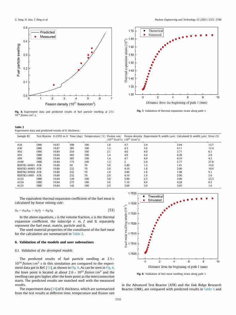
Fig. 6. Experiment data and predicted results of fuel particle swelling at 2:5�1014 fission=cm3$s.
Table 3Experiment data and predicted results of IL thickness.
Sample ID Test Reactor U-235% in U Time (day) Temperature (�C) Fission rate(1014 f/cm3s)
Fission density(1021 f/cm3s)
Experiment IL width (mm) Calculated IL width (mm) Error (%)
A34 ORR 19.87 300 100 1.8 4.7 3.4 3.94 13.7A36 ORR 19.87 385 100 1.3 4.3 3.6 4.11 12.4A92 ORR 19.84 254 100 2.1 4.6 4.0 3.77 6.1A93 ORR 19.84 402 100 1.4 4.9 4.4 4.28 2.8A99 ORR 19.84 385 100 1.4 4.7 4.0 4.19 4.5A100 ORR 19.84 175 100 1.3 2 2.0 2.77 27.8RERTR1-W001 ATR 19.80 94 70 3.0 2.40 1.2 1.41 14.9RERTR2-W003 ATR 19.80 232 70 2.0 4.10 1.8 2.00 10.0RERTR2-W004 ATR 19.80 232 70 1.9 3.90 1.8 1.98 9.1RERTR2-U005 ATR 19.80 232 70 2.0 4.10 1.9 2.00 5.0A123 ORR 19.84 120 100 3.8 3.90 2.3 3.00 23.3A124 ORR 19.84 275 100 3.0 7.10 4.0 4.28 6.5A125 ORR 19.84 142 100 2.9 3.60 3.0 3.05 1.6
Fig. 7. Validation of thermal expansion strain along path 1.
Fig. 8. Validation of fuel meat swelling strain along path 1.
G. Yang, H. Liao, T. Ding et al. Nuclear Engineering and Technology 53 (2021) 3723e3740
The equivalent thermal expansion coefficient of the fuel meat iscalculated by linear mixing rule:
ae ¼amnm þ af nf þ aILnIL (53)
In the above equations, v is the volume fraction, a is the thermalexpansion coefficient, the subscript e; m, f and IL separatelyrepresent the fuel meat, matrix, particle and IL.
The used material properties of the constituent of the fuel meatfor the calculation are summarized in Table 2.
6. Validation of the models and user subroutines
6.1. Validation of the developed models
The predicted results of fuel particle swelling at 2:5�1014 fission=cm3$s in this simulation are compared to the experi-ment data got in Ref. [13], as shown in Fig. 6. As can be seen in Fig. 6,the knee point is located at about 2:6� 1021 fission=cm3 and theswelling rate gets higher after the knee point as the interconnectionstarts. The predicted results are matched well with the measuredresults.
The experiment data [14] of IL thickness, which are summarizedfrom the test results at different time, temperature and fission rate
3732
in the Advanced Test Reactor (ATR) and the Oak Ridge ResearchReactor (ORR), are compared with predicted results in Table 3 and
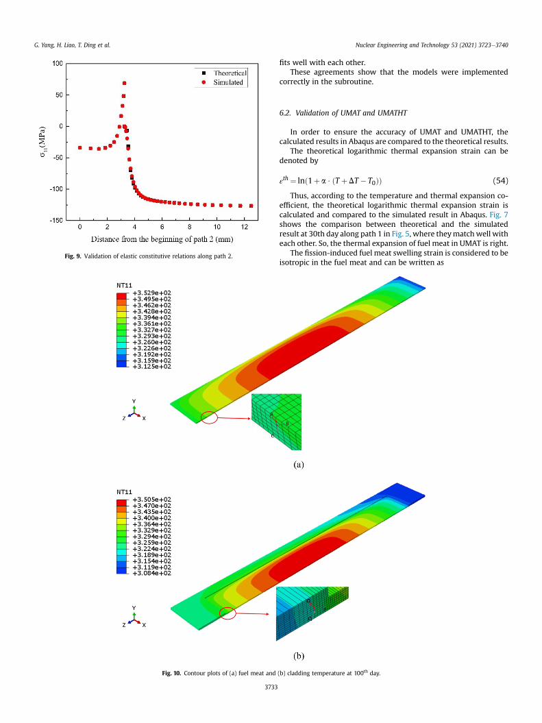
Fig. 9. Validation of elastic constitutive relations along path 2.
Fig. 10. Contour plots of (a) fuel meat and
G. Yang, H. Liao, T. Ding et al. Nuclear Engineering and Technology 53 (2021) 3723e3740
3733
fits well with each other.These agreements show that the models were implemented
correctly in the subroutine.
6.2. Validation of UMAT and UMATHT
In order to ensure the accuracy of UMAT and UMATHT, thecalculated results in Abaqus are compared to the theoretical results.
The theoretical logarithmic thermal expansion strain can bedenoted by
εth ¼ lnð1þ a $ ðT þDT � T0ÞÞ (54)
Thus, according to the temperature and thermal expansion co-efficient, the theoretical logarithmic thermal expansion strain iscalculated and compared to the simulated result in Abaqus. Fig. 7shows the comparison between theoretical and the simulatedresult at 30th day along path 1 in Fig. 5, where theymatchwell witheach other. So, the thermal expansion of fuel meat in UMAT is right.
The fission-induced fuel meat swelling strain is considered to beisotropic in the fuel meat and can be written as
(b) cladding temperature at 100th day.
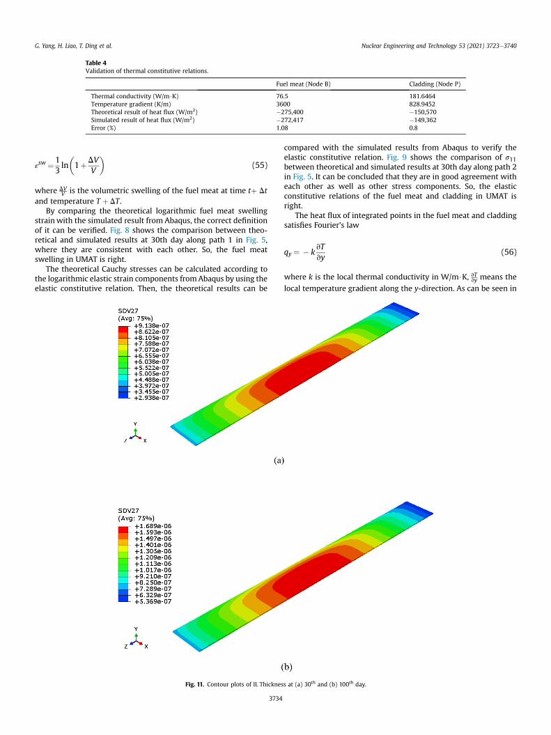
Table 4Validation of thermal constitutive relations.
Fuel meat (Node B) Cladding (Node P)
Thermal conductivity (W/m$K) 76.5 181.6464Temperature gradient (K/m) 3600 828.9452Theoretical result of heat flux (W/m2) �275,400 �150,570Simulated result of heat flux (W/m2) �272,417 �149,362Error (%) 1.08 0.8
G. Yang, H. Liao, T. Ding et al. Nuclear Engineering and Technology 53 (2021) 3723e3740
εsw ¼1
3ln�1þDV
V
�(55)
where DVV is the volumetric swelling of the fuel meat at time tþ Dt
and temperature T þ DT .By comparing the theoretical logarithmic fuel meat swelling
strainwith the simulated result from Abaqus, the correct definitionof it can be verified. Fig. 8 shows the comparison between theo-retical and simulated results at 30th day along path 1 in Fig. 5,where they are consistent with each other. So, the fuel meatswelling in UMAT is right.
The theoretical Cauchy stresses can be calculated according tothe logarithmic elastic strain components fromAbaqus by using theelastic constitutive relation. Then, the theoretical results can be
Fig. 11. Contour plots of IL Thicknes
3734
compared with the simulated results from Abaqus to verify theelastic constitutive relation. Fig. 9 shows the comparison of s11between theoretical and simulated results at 30th day along path 2in Fig. 5. It can be concluded that they are in good agreement witheach other as well as other stress components. So, the elasticconstitutive relations of the fuel meat and cladding in UMAT isright.
The heat flux of integrated points in the fuel meat and claddingsatisfies Fourier's law
qy ¼ � kvTvy
(56)
where k is the local thermal conductivity in W/m$K, vTvy means the
local temperature gradient along the y-direction. As can be seen in
s at (a) 30th and (b) 100th day.

Fig. 12. Contour plots of the thermal conductivity of the fuel meat at (a) 30th and (b) 100th day.
Fig. 13. Temperature evolution along path 3 with increasing irradiation time.
G. Yang, H. Liao, T. Ding et al. Nuclear Engineering and Technology 53 (2021) 3723e3740
Fig. 10, we choose some nodes from the fuel meat and cladding. Thetemperature and coordinate of each point can be got from Abaqus,
3735
then the theoretical result of heat flux can be calculated using Eq.(56). The comparison results are list in Table 4, where the theo-retical result matches well with the simulated result, proving theaccuracy of thermal constitutive relations.
7. Results and discussions
7.1. Temperature results of the fuel plate
The heat generated in the fuel meat is taken away by the high-speed coolant. Fig. 10 shows the temperature distribution of thefuel plate at 100th day. The temperature of the fuel meat, where theuranium fission happened, is higher than the cladding. Themaximum temperature of the fuel meat and cladding is 353 K and350 K, respectively. The temperature distribution is similar to thefission rate distribution. The high temperature region almost lo-cates at the middle of the fuel plate, which is due to the higherfission rate there. During the irradiation, IL formed between thefuel particles and the matrix. The thermal conductivity of the IL issmall compared to that of the fuel particle or the matrix. So, it couldhave some influence on the temperature of the fuel plate. Fig. 11shows the IL thickness at 30th and 100th day. The largest IL Thick-ness is about 1.689 mm during the simulation. The IL thicknessgradually increases with the increasing irradiation time.
G. Yang, H. Liao, T. Ding et al. Nuclear Engineering and Technology 53 (2021) 3723e3740
Meanwhile, the higher fission rate, the higher IL thickness. The ILthickness distribution is also similar to the fission rate distribution.The influence of IL formation can be observed from Fig. 12. Thisfigure shows the thermal conductivity of the fuel meat at 30th and100th day. The thermal conductivity getting lower with theincreasing IL thickness. However, in this simulation the irradiationtime and fission rate are not very large, so the difference in thethermal conductivity is not very large. At the same axial height, thethermal conductivity changes within 3 W=ðm $KÞ. This results in alittle difference in the temperature in the fuel meat, as can be seenin Fig. 13. This figure shows the temperature evolution underdifferent irradiation time along path 3. The maximum difference,which is about 0.8 K, mainly appears at the middle of the fuel meat.Because the IL thickness in themiddle of the fuel meat is larger thanother place, leading the thermal conductivity decreases larger. Thisphenomenon should be paid attention to when the fission rate islarge and the irradiation time is long. It can effectively decrease thethermal conductivity of the fuel meat as the IL grows.
7.2. Mechanical performance of the fuel plate
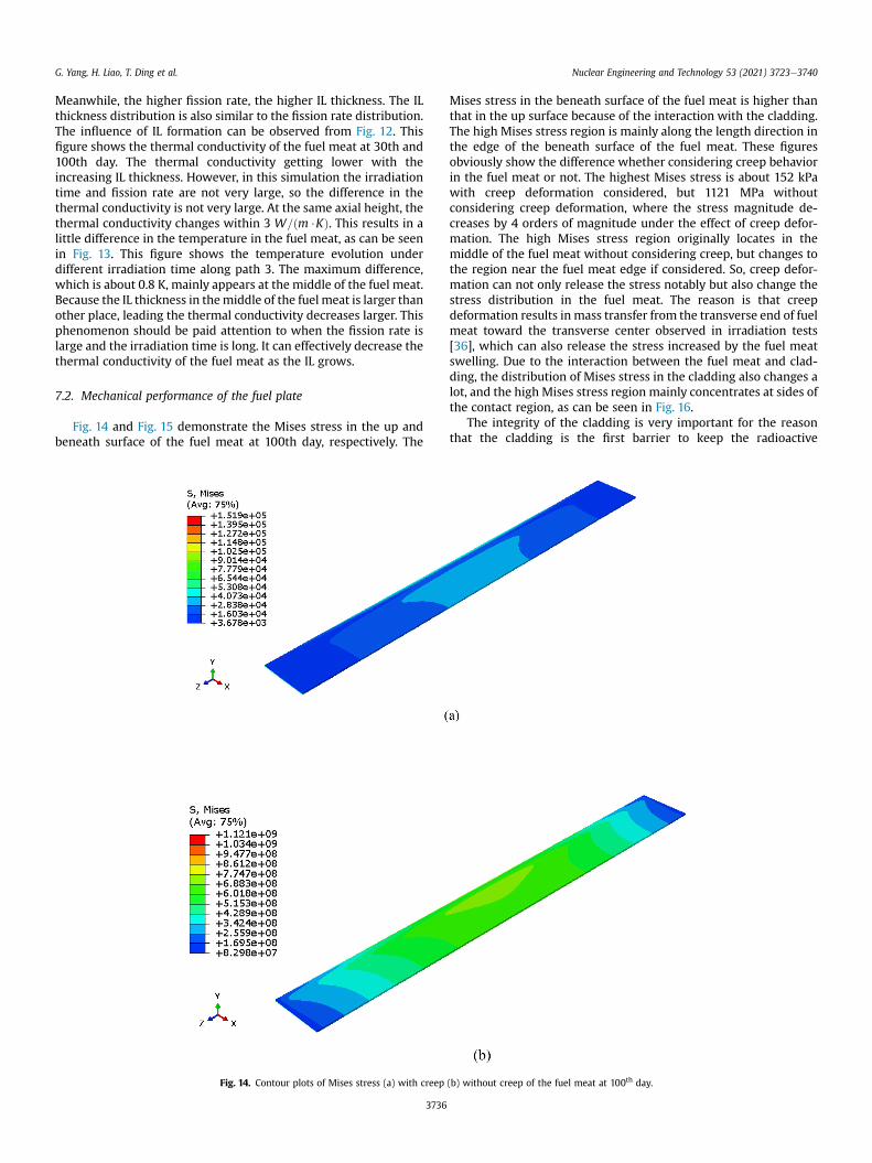
Fig. 14 and Fig. 15 demonstrate the Mises stress in the up andbeneath surface of the fuel meat at 100th day, respectively. The
Fig. 14. Contour plots of Mises stress (a) with creep
3736
Mises stress in the beneath surface of the fuel meat is higher thanthat in the up surface because of the interaction with the cladding.The high Mises stress region is mainly along the length direction inthe edge of the beneath surface of the fuel meat. These figuresobviously show the difference whether considering creep behaviorin the fuel meat or not. The highest Mises stress is about 152 kPawith creep deformation considered, but 1121 MPa withoutconsidering creep deformation, where the stress magnitude de-creases by 4 orders of magnitude under the effect of creep defor-mation. The high Mises stress region originally locates in themiddle of the fuel meat without considering creep, but changes tothe region near the fuel meat edge if considered. So, creep defor-mation can not only release the stress notably but also change thestress distribution in the fuel meat. The reason is that creepdeformation results in mass transfer from the transverse end of fuelmeat toward the transverse center observed in irradiation tests[36], which can also release the stress increased by the fuel meatswelling. Due to the interaction between the fuel meat and clad-ding, the distribution of Mises stress in the cladding also changes alot, and the high Mises stress region mainly concentrates at sides ofthe contact region, as can be seen in Fig. 16.
The integrity of the cladding is very important for the reasonthat the cladding is the first barrier to keep the radioactive
(b) without creep of the fuel meat at 100th day.

Fig. 15. Contour plots of Mises stress (a) with creep (b) without creep of the beneath surface of the fuel meat at 100th day.
G. Yang, H. Liao, T. Ding et al. Nuclear Engineering and Technology 53 (2021) 3723e3740
substance from leakage. As the fission progresses, the Mises stressof the fuel meat and cladding gets larger. The evolution of Misesstress in the fuel meat along path 4 in Fig. 15 is shown in Fig. 17. Thestress gets its maximum value near the edge of the beneath surfaceof the fuel meat and is relatively small in the opposite side. Thestress becomes larger with increasing irradiation time because in-pile behaviors induced deformation in the fuel meat gets larger.However, the magnitude and growth rate of stress is not too fast, ascreep deformation dominating in this progress and controlling therate of fuel volume transport. The fuel meat and cladding are in-tegrated metallurgy as frame type. So, the stress in the fuel meatand cladding influence each other greatly. The deformation of thefuel meat gets larger, the extrusion between the fuel meat andcladding gets more intense, leading to larger stress in the cladding.Fig. 18 and Fig. 19 show the evolution of Mises stress in the claddingalong path 5 in Fig. 5 and path 7 in Fig. 16. It can be concluded thatthe high Mises stress mainly concentrates near the side edge of theinterface, which can also be seen in the contour plot shown inFig. 16. The maximum stress is about 162.6 MPa in the cladding, farfrom the yield strength of the Al. Due to the low stress, the plasticitydeformation does not occur in the cladding in this study. For thesake of in-pile safety, these highMises stress regions should be paidmore attention to during the manufacturing process.
7.3. Deformation of the fuel plate
Fuel plates form narrow rectangular channels in the reactor.The coolant flows in it and takes away the heat generated by fuelparticles. The size of these channels is about millimeters. Due to
3737
high irradiation, fuel plates can deform easily, which may disturbcoolant in the narrow flow channel at relatively serious condi-tions. Hence, the deformation of fuel plate is essential to the safetyof the reactor. Fig. 20 demonstrates the displacement of thecladding at 30th and 100th day. The maximum displacement ofthe fuel plate is 7.019 mm. The largest displacement appears at themiddle of the contact region. The main reason is that the irradi-ation swelling contributes a lot and the swelling is largest in themiddle with the highest fission rate and the highest temperaturethere. Many irradiation experiments [8,9] have proved swelling isthe main reason for the volume change of the fuel plate. Thedisplacement of cladding gets larger with increasing irradiationtime along path 6, as shown in Fig. 21. However, it can beconcluded in this work that the deformation of the fuel plate isrelatively small comparing to the typical thickness of the fuel plateor size of the coolant channel.
8. Conclusions
In this research, the three-dimensional stress update algorithmsfor the U3Si2/Al dispersion fuel plate have been developed to studyits thermal-mechanical performance under normal conditions us-ing finite element software Abaqus. Many in-pile behaviors,including thermal expansion, fission-induced swelling, IL growth,creep for the fuel meat and plasticity for the cladding, are taken intoconsideration to evaluate the effect on the stress and deformationof the fuel plate at different irradiation time. The conclusions are asfollows:

Fig. 16. Contour plots of Mises stress (a) with creep (b) without creep of the cladding at 100th day.
Fig. 17. Evolution of Mises stress in the fuel meat along path 4. Fig. 18. Evolution of Mises stress in the cladding along path 5.
G. Yang, H. Liao, T. Ding et al. Nuclear Engineering and Technology 53 (2021) 3723e3740
3738
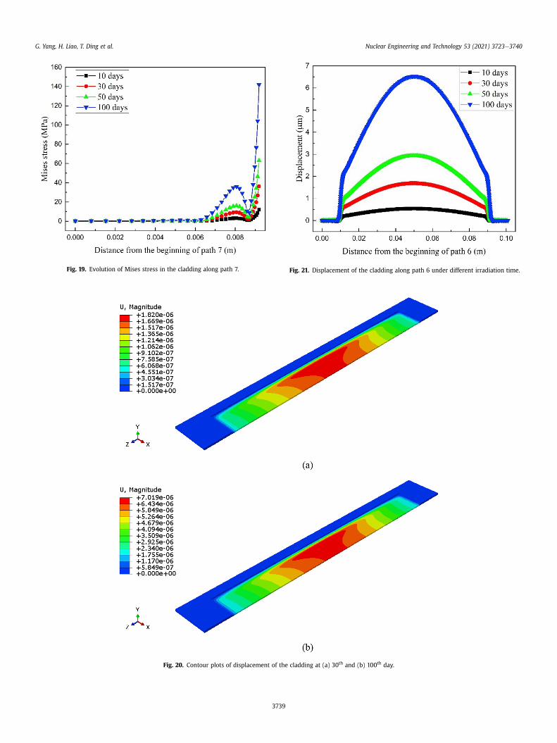
Fig. 19. Evolution of Mises stress in the cladding along path 7. Fig. 21. Displacement of the cladding along path 6 under different irradiation time.
Fig. 20. Contour plots of displacement of the cladding at (a) 30th and (b) 100th day.
G. Yang, H. Liao, T. Ding et al. Nuclear Engineering and Technology 53 (2021) 3723e3740
3739
G. Yang, H. Liao, T. Ding et al. Nuclear Engineering and Technology 53 (2021) 3723e3740
(1) A detailed model for the fuel meat swelling is developedbased on published literature. Models and algorithms areprogrammed into the user subroutines of Abaqus. They arevalidated with experimental data and theoretical results,which matches well with each other, proving the correctdefinition of them.
(2) In this simulation, although the maximum IL thickness is1.689 mm, but it can effectively decrease the thermal con-ductivity of the fuel meat, especially under the large fissionrate and long irradiation time.
(3) The high Mises stress region mainly locates at the interfacebetween the fuel meat and cladding, especially the side edgeof the interface. The stress in the fuel meat increases underthe influence of fuel meat swelling and thermal expansion,but then effectively releases by 4 orders of magnitudebecause of creep deformation.
(4) For the cladding, the plasticity deformation does not appearwithin the irradiation time. The maximum displacement isabout 7.019 mm, which is relatively small comparing to thetypical thickness of the fuel plate.
Declaration of competing interest
The authors declare that they have no known competingfinancial interests or personal relationships that could haveappeared to influence the work reported in this paper.
References
[1] D.F. Chen, et al., Development of neutron scattering on 60 MW researchreactor in CIAE, Phys. B Condens. Matter 385 (2006) 966e967.
[2] Daxin Gong, et al., "Heat transfer calculation on plate-type fuel assembly ofhigh flux research reactor.", Science and Technology of Nuclear Installations2015 (2015).
[3] K. B€oning, W. Petry, Test irradiations of full-sized U3Si2eAl fuel plates up tovery high fission densities, J. Nucl. Mater. (2009) 254e263, 383.3.
[4] Daniel Iracane, Pascal Chaix, Ana Alamo, Jules Horowitz Reactor: a high-performance material testing reactor, Comptes Rendus Physique 9.3-4(2008) 445e456.
[5] Armando Travelli, Effect of Reduced Enrichment on the Fuel Cycle forResearch Reactors, Argonne National Lab, IL (USA), 1982. No. CONF-820420e12.
[6] J.L. Snelgrove, RERTR Program Fuel Development and Testing-The Past Yearand the Next, 1988. No. ANL/RERTR/TMe9.
[7] D.D. Keiser, et al., "High-density, low-enriched uranium fuel for nuclearresearch reactors.", JOM (J. Occup. Med.) 55 (9) (2003) 55e58.
[8] Kim, Yeon Soo, et al., Temperature and dose dependence of fission-gas-bubbleswelling in U3Si2, J. Nucl. Mater. (2009) 443e449, 389.3.
[9] Nuclear Regulatory Commission, Safety Evaluation Report Related to TheEvaluation Of Low-Enriched Uranium Silicide-Aluminum Dispersion Fuel ForUse In Non-Power Reactors, Nuclear Regulatory Commission, 1988. No.NUREGe1313.
[10] Ann Leenaers, et al., Post-irradiation examination of AlFeNi cladded U3Si2 fuelplates irradiated under severe conditions, J. Nucl. Mater. (2008) 243e251,375.2.
3740
[11] Jian Gan, et al., Microstructure of the irradiated U3Si2/Al silicide dispersionfuel, J. Nucl. Mater. (2011) 97e104, 419.1-3.
[12] R.C. Birtcher, J.W. Richardson, M.H. Mueller, Amorphization of U3Si2 by ion orneutron irradiation, J. Nucl. Mater. (1996) 158e163, 230.2.
[13] J. Rest, A model for fission-gas-bubble behavior in amorphous uranium sili-cide compounds, J. Nucl. Mater. (2004) 107e117, 325.2-3.
[14] Yeon Soo Kim, Gerard L. Hofman, Interdiffusion in U3SieAl, U3Si2eAl, andUSieAl dispersion fuels during irradiation, J. Nucl. Mater. (2011) 1e9, 410.1-3.
[15] Y.S. Kim, et al., MODELING OF INTERACTION LAYER GROWTH BETWEEN U-MoPARTICLES AND AN Al MATRIX, Nuclear Engineering and Technology 45(2013) 827e838.
[16] J. Rest, The DART Dispersion Analysis Research Tool: A Mechanistic Model forPredicting Fission-Product-Induced Swelling of Aluminum Dispersion Fuels.Users Guide for Mainframe, Workstation, and Personal Computer Applica-tions, Argonne National Lab, IL (United States), 1995. No. ANL-95/36.
[17] Kim, Yeon Soo, et al., "Fission induced swelling of UeMo/Al dispersion fuel.",J. Nucl. Mater. 465 (2015) 142e152.
[18] Kathryn E. Metzger, Analysis of Pellet Cladding Interaction and Creep of U3Si2Fuel for Use in Light Water Reactors, Diss, University of South Carolina, 2016.
[19] Abaqus, User's Manual, 2013 (Dassault Systems, Pawtucket), version 6.13.[20] X. Gong, et al., A new method to simulate the micro-thermo-mechanical be-
haviors evolution in dispersion nuclear fuel elements, Mech. Mater. 77 (2014)14e27.
[21] Fionn Dunne, Introduction to Computational Plasticity, Oxford UniversityPress, 2005.
[22] Yukio Sudo, et al., Experimental study of differences in single-phase forced-convection heat transfer characteristics between upflow and downflow fornarrow rectangular channel, J. Nucl. Sci. Technol. (1985) 202e212, 22.3.
[23] W.Y. Hsu, T. Berzins, Percolation and effective-medium theories for per-fluorinated ionomers and polymer composites, J. Polym. Sci. Polym. Phys. Ed(1985) 933e953, 23.5.
[24] B. Badrinarayan, J.W. Barlow, Prediction of the thermal conductivity of bedswhich contain polymer coated metal particles, in: 1990 International SolidFreeform Fabrication Symposium, 1990.
[25] E.J. Garboczi, J.G. Berryman, Elastic moduli of a material containing compositeinclusions: effective medium theory and finite element computations, Mech.Mater. 33 (8) (2001) 455e470.
[26] R.M. Christensen, K.H. Lo, Solutions for effective shear properties in threephase sphere and cylinder models - ScienceDirect, J. Mech. Phys. Solid. 27 (4)(1979) 315e330.
[27] Z. Hashin, S. Shtrikman, A variational approach to the theory of the elasticbehaviour of multiphase materials, J. Mech. Phys. Solid. 11 (2) (1963)127e140.
[28] H. Shimizu, The properties and irradiation behavior of U3Si2, Br. J. Haematol.(1965) 556e573, 120.4.
[29] M.R. Finlay, G.L. Hofman, J.L. Snelgrove, Irradiation behaviour of uraniumsilicide compounds, J. Nucl. Mater. (2004) 118e128, 325.2-3.
[30] G.Y. Jeong, Y.S. Kim, D.S. Sohn, Mechanical analysis of UMo/Al dispersion fuel,J. Nucl. Mater. 466 (2015) 509e521.
[31] Zhi-Gang, et al., First-principles study of structural, elastic, electronic, vibra-tional and thermodynamic properties of uranium aluminides, Comput. Mater.Sci. 158 (2019) 26e31.
[32] S. Nazar�e, G. Ondracek, F. Thümmler, "Investigations on UAlx-Al dispersionfuels for high-flux reactors, J. Nucl. Mater. (1975) 251e259, 56.3.
[33] Ozaltun Hakan, M.-H. Herman Shen, Pavel Medvedev, Assessment of residualstresses on U10Mo alloy based monolithic mini-plates during Hot IsostaticPressing, J. Nucl. Mater. (2011) 76e84, 419.1-3.
[34] Kim, Yeon Soo, et al., Fission induced swelling and creep of UeMo alloy fuel,J. Nucl. Mater. (2013) 37e46, 437.1-3.
[35] F. Cardarelli, Materials Handbook A Concise Desktop Reference, second ed.,,Springer, New York, London, 2005. ISBN 978-1-84628-668-1.
[36] Gwan Yoon Jeong, et al., Mechanical analysis of UMo/Al dispersion fuel,Journal of Nuclear Materials Aspects of Fission & Fusion (2015).