FAA Certification of Cold Spray Dimensional Repair. - Safe ...
33
FAA Certification of Cold Spray Dimensional Repair Ms. Sarah Galyon Dorman Dr. Scott Fawaz (RS-DER Structures Fatigue & Damage Tolerance) Cold Spray Action Team 25-26 June 2019 The views and conclusions contained herein are those of the authors and should not be interpreted as necessarily representing the official policies and endorsements, either expressed or implied of the US Air Force Academy or the US Government. Distribution Statement A.
-
Upload
khangminh22 -
Category
Documents
-
view
1 -
download
0
Transcript of FAA Certification of Cold Spray Dimensional Repair. - Safe ...

FAA Certification of Cold Spray Dimensional Repair
Ms. Sarah Galyon DormanDr. Scott Fawaz (RS-DER Structures
Fatigue & Damage Tolerance)Cold Spray Action Team
25-26 June 2019The views and conclusions contained herein are those of the authors and should not be interpreted as necessarily representing the official policies and endorsements, either expressed or implied of
the US Air Force Academy or the US Government. Distribution Statement A.

Outline
• FAA Repair Approval Process• Material Test Plan and Results• Repair Substantiation - Analysis• Example Repair• New Program

FAA Repair Approval Process
Federal Aviation Regulations (FARs)– Part of Title 14 of the Code of Federal Regulations (CFR)– Prescribed by the Federal Aviation Administration (FAA) and governs
all aviation activities in the United States• Regulations for certification of aircraft and components
– Part 21 –Certification Procedures for Products and Parts – Part 23 –Airworthiness Standards: Normal, Utility, Acrobatic
and Commuter Airplanes – Part 25 –Airworthiness Standards: Transport Category
Airplanes – Part 27 –Airworthiness Standards: Normal Category Rotorcraft – Part 29 –Airworthiness Standards: Transport Category
Rotorcraft

FAA Repair Approval Process
Repair Specification (RS)
Specific Aircraft/Component
RepairVS.
• Multiple-use, major repair • Applicable to multiple
aircraft• RS-DER approval of
engineering data
• Single-use, major repair• Limited applicability
– Aircraft serial numbers identified on Form 8110-3
• DER approval of engineering data
Dimensional or Structural Repair – determines the breadth and depth of analysis and testing required for certification

Compliance Checklist
FAR Section Amendment LevelB767 Description
25.301 25-23 Loads
25.303 25-23 Factors of Safety
25.305 25-86 Strength and Deformation
25.307 25-72 Proof of Structure
25.571 25-96 Fatigue & Damage Tolerance
25.601 Design and Construction: General
25.603 25-46 Materials
25.605 25-46 Fabrication Methods
25.607 25-23 Fasteners
25.609 Protection of Structure
25.611 25-23 Accessibility Provisions
25.613 25-112 Material Strength
26.43(c), (d) 26-1 Holders of and applicants for type certificates - Repairs

Data Package Requirements for Repair Substantiation
• Dimensional Repair (DR): Non-structural (small loads)– Specifications and requirements– Process optimization – powder processing, surface prep, spray
parameters – Spray Quality
• Microstructural characterization - porosity • Mechanical property characterization – hardness, adhesion
– Mechanical property characterization - wear– Corrosion performance – salt fog, exfoliation
• Structural Repair (SR): Structural (loaded)– Dimensional repair data package– Mechanical and fatigue property characterization IAW MMPDS
• Specific application drives requirements (Testing or Analysis Required)

SAFE-RPT-16-013 (C) Cold Spray Repair - Certification Plan
SAFE-RPT-16-014 (NC) Structural Substantiation Overview(25.301, .303, .305, .307, .603, .605, .609, .611, .613, 25.571, 26.43)
SAFE-RPT-16-032 (NC)
437AL Structural
Substantiation
SAFE-PSPS-16-001 (NC) Part
Specific Process Specification Boeing 767 Pylon Panel
437AL
SAFE-RPT-16-033 (NC)
437AR SPD Structural
Substantiation
SAFE-PSPS-16-002 (NC) Part
Specific Process Specification Boeing 767 Pylon Panel
437AR
SAFE-RPT-16-034 (NC)
437ELX SPD Structural
Substantiation
SAFE-PSPS-16-003 (NC) Part
Specific Process Specification Boeing 767 Pylon Panel
437ELX
SAFE-RPT-16-035 (NC)
Airload Rib SPD Structural Substantiation
SAFE-PSPS-16-004 (NC) Part
Specific Process Specification
767 Airload Rib at OSS 456.975
SAFE-RPT-16-037 (NC) 767 Main Landing Gear Wheel
SPD Structural Substantiation
SAFE-PSPS-16-006 (NC) Part
Specific Process Specification Boeing 767
Main Landing Gear Wheel
SAFE-RPT-16-015 (NC) Material Characterization Testing
(25.601, .603, .605, .609)
SAFE-RPT-16-049 (NC) Test Results for Area Percentage Porosity
Determination of Cold Spray Coatings
(25.601, .603, .605, .609)
SAFE-GTP-16-001 (NC) Test Plan for Area Percentage
Porosity Determination of
Cold Spray Coatings(25.601, .603, .605, .609)
SAFE-RPT-16-050 (NC) Test Results for
Indentation Testing of Cold Spray Coatings
(25.601, .603, .605, .609)
SAFE-GTP-16-002 (A) Test Plan for
Indentation Testing of Cold Spray
Coatings(25.601, .603, .605, .609)
SAFE-RPT-16-057 (NC) Test Results for Salt
Spray (Fog) Corrosion Resistance of Cold Spray
Materials(25.601, .603, .605, .609)
SAFE-GTP-16-009 (NC) Salt Spray (Fog) Corrosion Resistance
of Cold Spray Materials
(25.601, .603, .605, .609)
SAFE-RPT-16-058 (NC) Test Results for
Exfoliation Corrosion Susceptibility in 2xxx and
7xxx Series Cold Spray Alloys
(25.601, .603, .605, .609)
SAFE-GTP-16-010 (NC) Test Plan
Exfoliation Corrosion Susceptibility in 2xxx and 7xxx Series Cold
Spray Alloys(25.601, .603, .605, .609)
SAFE-RPT-16-062 (NC) Test Results for Linearly Reciprocating Ball-on-
Flat Sliding Wear of Cold Spray Materials
(25.601, .603, .605, .609)
SAFE-GTP-16-015 (A) Test Plan for Linearly Reciprocating Ball-
on-Flat Sliding Wear of Cold Spray
Materials(25.601, .603, .605, .609)
SAFE-PS-16-001 (C) Process Specification - Cold Spray Repair
CS Control Sheet S010-CSS-00002
SAFE-FRM-007 (NC) Cold Spray Inspection Report
SAFE-PS-16-003 (A) Process Specification - Cold Spray Acceptance Criteria
Acceptable Data
Approved Data

Part Specific Process Specification

SAFE-RPT-16-013 (C) Cold Spray Repair - Certification Plan
SAFE-RPT-16-014 (NC) Structural Substantiation Overview(25.301, .303, .305, .307, .603, .605, .609, .611, .613, 25.571, 26.43)
SAFE-RPT-16-032 (NC)
437AL Structural
Substantiation
SAFE-PSPS-16-001 (NC) Part
Specific Process Specification Boeing 767 Pylon Panel
437AL
SAFE-RPT-16-033 (NC)
437AR SPD Structural
Substantiation
SAFE-PSPS-16-002 (NC) Part
Specific Process Specification Boeing 767 Pylon Panel
437AR
SAFE-RPT-16-034 (NC)
437ELX SPD Structural
Substantiation
SAFE-PSPS-16-003 (NC) Part
Specific Process Specification Boeing 767 Pylon Panel
437ELX
SAFE-RPT-16-035 (NC)
Airload Rib SPD Structural Substantiation
SAFE-PSPS-16-004 (NC) Part
Specific Process Specification
767 Airload Rib at OSS 456.975
SAFE-RPT-16-037 (NC) 767 Main Landing Gear Wheel
SPD Structural Substantiation
SAFE-PSPS-16-006 (NC) Part
Specific Process Specification Boeing 767
Main Landing Gear Wheel
SAFE-RPT-16-015 (NC) Material Characterization Testing
(25.601, .603, .605, .609)
SAFE-RPT-16-049 (NC) Test Results for Area Percentage Porosity
Determination of Cold Spray Coatings
(25.601, .603, .605, .609)
SAFE-GTP-16-001 (NC) Test Plan for Area Percentage
Porosity Determination of
Cold Spray Coatings(25.601, .603, .605, .609)
SAFE-RPT-16-050 (NC) Test Results for
Indentation Testing of Cold Spray Coatings
(25.601, .603, .605, .609)
SAFE-GTP-16-002 (A) Test Plan for
Indentation Testing of Cold Spray
Coatings(25.601, .603, .605, .609)
SAFE-RPT-16-057 (NC) Test Results for Salt
Spray (Fog) Corrosion Resistance of Cold Spray
Materials(25.601, .603, .605, .609)
SAFE-GTP-16-009 (NC) Salt Spray (Fog) Corrosion Resistance
of Cold Spray Materials
(25.601, .603, .605, .609)
SAFE-RPT-16-058 (NC) Test Results for
Exfoliation Corrosion Susceptibility in 2xxx and
7xxx Series Cold Spray Alloys
(25.601, .603, .605, .609)
SAFE-GTP-16-010 (NC) Test Plan
Exfoliation Corrosion Susceptibility in 2xxx and 7xxx Series Cold
Spray Alloys(25.601, .603, .605, .609)
SAFE-RPT-16-062 (NC) Test Results for Linearly Reciprocating Ball-on-
Flat Sliding Wear of Cold Spray Materials
(25.601, .603, .605, .609)
SAFE-GTP-16-015 (A) Test Plan for Linearly Reciprocating Ball-
on-Flat Sliding Wear of Cold Spray
Materials(25.601, .603, .605, .609)
SAFE-PS-16-001 (C) Process Specification - Cold Spray Repair
CS Control Sheet S010-CSS-00002
SAFE-FRM-007 (NC) Cold Spray Inspection Report
SAFE-PS-16-003 (A) Process Specification - Cold Spray Acceptance Criteria
Acceptable Data
Approved Data

Process Specification

Test Program-Dimensional Repair
• Porosity• Hardness• Corrosion – Salt Fog• Corrosion – Exfoliation• Wear
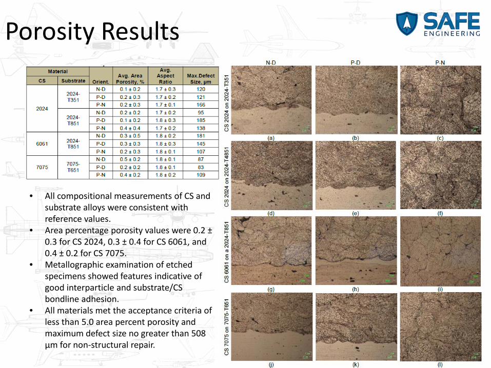
Porosity Results
• All compositional measurements of CS and substrate alloys were consistent with reference values.
• Area percentage porosity values were 0.2 ±0.3 for CS 2024, 0.3 ± 0.4 for CS 6061, and 0.4 ± 0.2 for CS 7075.
• Metallographic examination of etched specimens showed features indicative of good interparticle and substrate/CS bondline adhesion.
• All materials met the acceptance criteria of less than 5.0 area percent porosity and maximum defect size no greater than 508 μm for non-structural repair.

Hardness Results
• Processed powder hardness was consistent with the O-temper (annealed condition).
• Vickers hardness values were• 125 HV for 2024• 88 HV for 6061• 121 HV for 7075• Uncertainty was 13 to 21 HV
• CS hardness was always less than the substrate material

Corrosion – Salt Fog Results
• CS 2024 exhibited comparable corrosion resistance compared to 2024-T351 and 2024-T81
• CS 6061 exhibited greater general corrosion resistance than 2014-T652• CS 7075 less susceptible to intergranular corrosion than 7075-T651

Corrosion – Exfoliation Results
• Comparable corrosion resistance of CS 2024 to 2024-T351 and 2024-T81• Comparable corrosion resistance of 2014-T562 to 2024-T351 and 2024-T81
• 6061 does not exfoliate; thus a comparison to wrought products is not relevant
• Corrosion resistance of CS 7075 was superior to 7075-T651

Wear Results
• For all CS materials, the coefficient of friction was consistently comparable to or higher than the reference materials.

Repair Outside SRM Limits
• Boeing 767 Parts– Engine pylon panels (3)– Airload rib– Main landing gear wheel
• Damage Mechanisms– Corrosion– Chafing– Fretting– Mechanical damage
• Repair Type– Dimensional– Structural

Analysis Approach
• Develop a repair specification (non-tail number specific)
• Damage scenario unknown a’priori• Determine worst case - maximum damage
allowable• Repair Scenarios
A. Surface RepairB. Fastener Repair

Scenario A – Surface Repair
Load Determinations • Maximum Load Critical Fastener Load
– Lift– Drag (bearing, shear tear out, net section tension)– FEA to account for geometry effects
• Maximum Cold Spray Thickness– Bearing– Shear Tearout– Net Section Tension– Fastener Pull Through
Failure Mode Maximum xcs-437Al (in)
Bearing Stress e/D=2.0 0.080
Bearing Stress e/D=1.5 0.080
Shear Tearout 0.080
Net Section Tension 0.080
Fastener Pull-Through 0.030
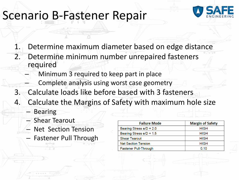
Scenario B-Fastener Repair
1. Determine maximum diameter based on edge distance2. Determine minimum number unrepaired fasteners
required– Minimum 3 required to keep part in place– Complete analysis using worst case geometry
3. Calculate loads like before based with 3 fasteners4. Calculate the Margins of Safety with maximum hole size
– Bearing– Shear Tearout– Net Section Tension– Fastener Pull Through
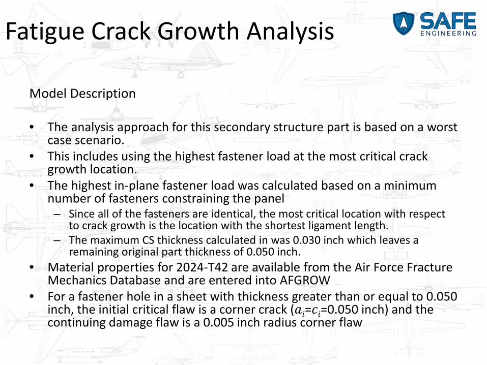
Fatigue Crack Growth Analysis
Model Description
• The analysis approach for this secondary structure part is based on a worst case scenario.
• This includes using the highest fastener load at the most critical crack growth location.
• The highest in-plane fastener load was calculated based on a minimum number of fasteners constraining the panel – Since all of the fasteners are identical, the most critical location with respect
to crack growth is the location with the shortest ligament length. – The maximum CS thickness calculated in was 0.030 inch which leaves a
remaining original part thickness of 0.050 inch.• Material properties for 2024-T42 are available from the Air Force Fracture
Mechanics Database and are entered into AFGROW• For a fastener hole in a sheet with thickness greater than or equal to 0.050
inch, the initial critical flaw is a corner crack (𝑎𝑎𝑖𝑖=𝑐𝑐𝑖𝑖=0.050 inch) and the continuing damage flaw is a 0.005 inch radius corner flaw

Fatigue Crack Growth AnalysisAFGROWCountersunk Hole and Double, Symmetric Corner Cracks Model
Crack Growth Below Threshold-No Crack Growth

Analysis Summary
• Verify a pylon panel repaired with CS meets structural and damage tolerance requirements. • Two CS repair scenarios were analyzed:
A. Surface repair with CS B. Local fastener repair with CS.
• The analysis approach was very conservative for both repair scenarios, either of which may be used
• Scenario A, a maximum CS thickness was calculated– All margins of safety for strength calculations were HIGH based on no load carrying
capability of the CS except for fastener pull-through which is constrained the CS thickness
– Scenario A – surface grindout and CS restoration in the area around any combination of fastener holes up to a maximum depth was determined
• Scenario B, was to identify the maximum number of fastener locations that could be repaired – Up to any 9 of the 12 fastener holes can be repaired using the oversize and CS
restoration technique, as long as there is at least one unrepaired fastener on each vertical edge
– The maximum oversize diameter was determined

Boeing 767 Pylon Panel Repair
Re-machined to original dimension
Unmachined CS for comparison

Structural RepairTesting Requirements
Test Standard Test Standard
Metallography ASTM E2109 Fatigue Stress Life ASTM E466
Hardness ASTM E2546 Fatigue Crack Growth Rate ASTM E647
Wear ASTM G133 Fracture Toughness ASTM E399
Salt Fog Corrosion ASTM B117 Triple Lug Shear MIL-J-2445a (SH)
Exfoliation ASTM G34 Glued Bond ASTM C633
Tensile ASTM E8 Pin Type Bearing ASTM E238
Compression ASTM E9

New ONR Funded ProgramApproach
Process: • Use a standardized process parameter
– Spray parameter, nozzle specific, powder processing if any– Validate the process parameters developed by other members in
the programMechanical Equivalency:
• Comparison of mechanical properties between pristine, unrepaired and CS coupons
Corrosion Equivalency:• Comparison of corrosion behavior between pristine and CS coupons
Substrate Evaluation:• Determine maximum temperature and cooling curve during the spray
operation• Cross section and determine if there is any heat affected zone

Experimental Outline
Plate Materials (0.25 inch): • Base Alloys: 7050-T7451 (AMS 4050), 7075-T651 (AMS 4045) Plates • CS: Al 7050 and 7075 powders – D90% - 58µm, D50% - 31µm and D10% - 10 µm• Galvanic Effects: Aluminum rivet and steel Hi-Locks• Percentage repair thickness 5%, 10% and 15%; possibly some through thickness repairs • Carrier gas – Helium
Sheet Materials (0.063 inch): • Base Alloys: 7075-T6 sheet (AMS 4045) (0.063)• CS: Al 7075– D90% - 58µm, D50% - 31µm and D10% - 10 µm• Galvanic Effects: Aluminum rivet• Percentage repair thickness: 15% • Carrier gas – Helium
Characterization:• Interface characteristics, defect analysis (porosity)• Mechanical Properties (Baselines pristine sample and unrepaired blend out)
– Static (tensile), bearing and fatigue • Corrosion
– Salt Fog (ASTM B117), exfoliation corrosion (ASTM G34) – Corrosion impact on mechanical damage– Fastener joints

Repair Geometry
• Sample designs are to have a 5%, 10% or 15% depth blend out of a 0.25 inch thick plate to represent allowable corrosion blend outs. The surface dimensions of the blend outs will be within the 10:1 width and 20:1 length ratios as a minimum

Tensile Samples
5% Repair (0.0125”)
15% Repair (0.0375”)
10% Repair (0.025”)Gage Width=0.5 inch
0.75 inch
Sample Dimensions Same For all Blend OutsSamples will be the LT material orientation
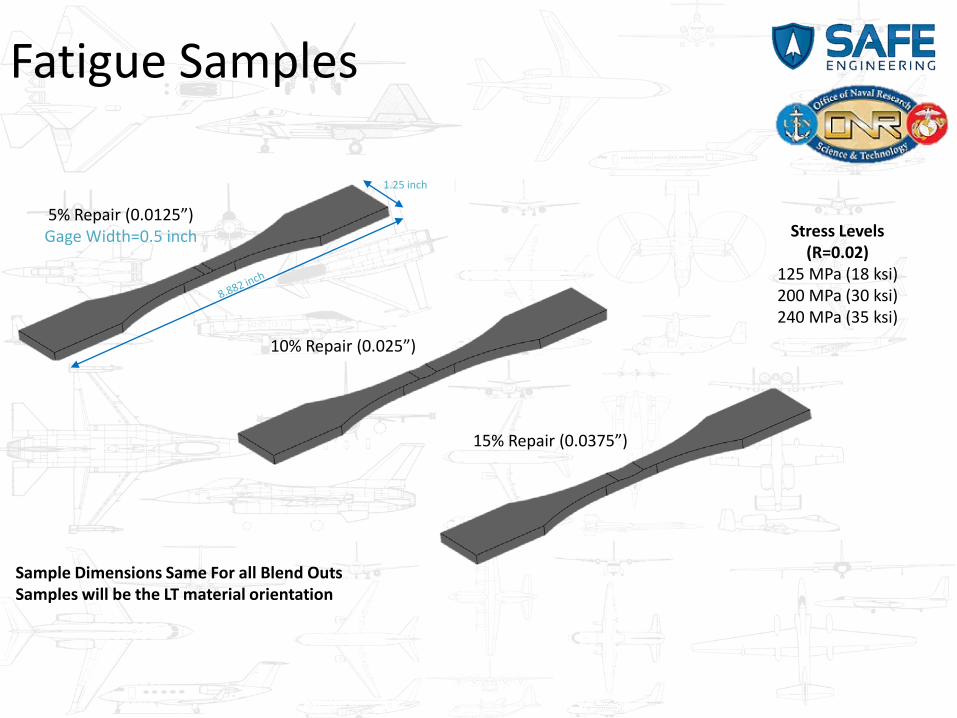
Fatigue Samples
5% Repair (0.0125”)Gage Width=0.5 inch
15% Repair (0.0375”)
10% Repair (0.025”)
Stress Levels (R=0.02)
125 MPa (18 ksi)200 MPa (30 ksi)240 MPa (35 ksi)
Sample Dimensions Same For all Blend OutsSamples will be the LT material orientation
1.25 inch
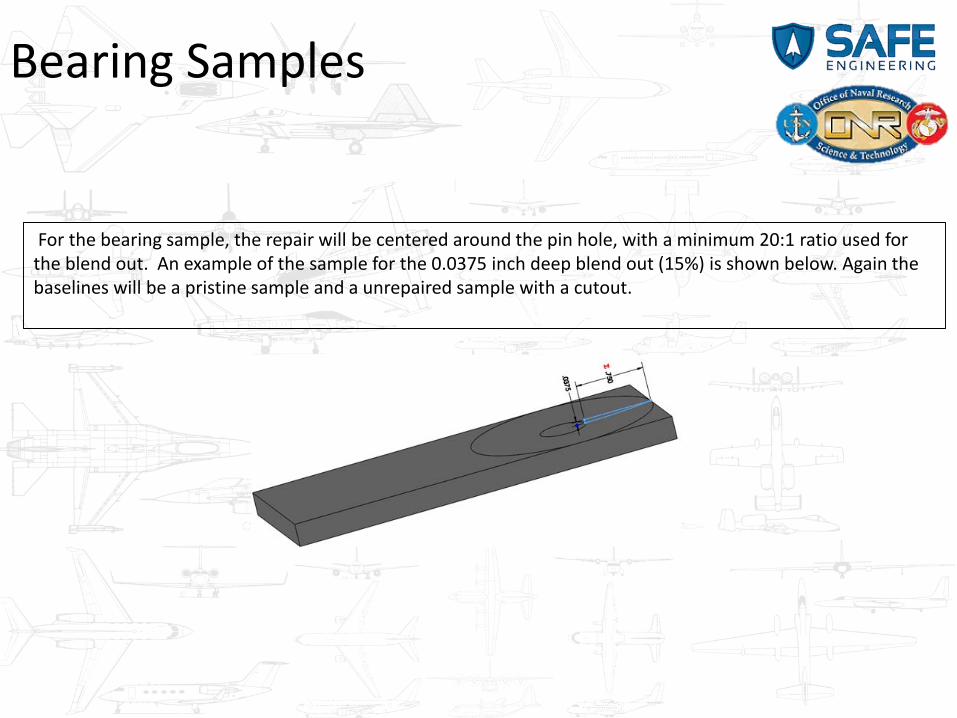
Bearing Samples
For the bearing sample, the repair will be centered around the pin hole, with a minimum 20:1 ratio used for the blend out. An example of the sample for the 0.0375 inch deep blend out (15%) is shown below. Again the baselines will be a pristine sample and a unrepaired sample with a cutout.

Corrosion and Galvanic Effects
• Sample with fastener added is exposed to EXCO solution per ASTM G34
• Tensile and fatigue testing completed to determine effect of corrosion damage and galvanic couple
• Baseline sample with no CS with fastenerFastener Added:
Al or SS
3290 Hamal CircleMonument, CO 80132
719.375.5855
A Service Disabled Veteran Owned Business
Contact Email: [email protected] page: http://saf-engineering.com/Publications: http://saf-engineering.com/publications.htmlServices: http://saf-engineering.com/services.htmlTest Capabilities: http://saf-engineering.com/services/testing.html