F/A-18A-D Hornet PCL (Pocket Check List) NATOPS - Troopers
16
LATERAL WEIGHT ASYMMETRY LIMITS Field takeoff 22,000 ft-lbs Catapult takeoff Weight board ≤ 36,000 lbs 6,000 ft-lbs Weight board ≥ 37,000 lbs 22,000 ft-lbs Inflight conditions 26,000 ft-lbs Asymmetric jettison/normal release of a store from station 2 or 8 that weighs in excess of 2330 pounds (i.e., GBU-24, MK-60, MK- 65, Walleye II ER/DL) exceeds the lateral weight asymmetry limitation and is prohibited (even if this is the normal SMS release sequence, except in an emergency). FCLP or Carrier landing with gross wt ≤ 33,000 lbs. (including wingtip AIM-9 and wing fuel) 17,000 ft-lbs Carrier landing with gross wt > 33,000 lbs. (including wingtip AIM-9 and wing fuel) 14,500 ft-lbs Field landing (flared) with sink rate at touchdown up to 500 fpm 26,000 ft-lbs ANGLE-OF-ATTACK LIMITATIONS Flaps AUTO CONFIGURATION AOA LIMIT (°) CG (% MAC) FE Unrestricted −6° to +25° 17 to 25% 25 to 28% FE plus centerline tanks/ stores Unrestricted −6° to +25° 17 to 23.5% 23.5 to 28% FE plus inboard tanks/ stores (with centerline tank/ stores) −6° to +25° 17 to 27.5% FE plus inboard tanks/ stores (without centerline tank/ stores) −6° to +35° −6° to +25° 17 to 24% 24 to 27.5% FE plus outboard tanks/ stores (centerline tank/ stores optional) −6° to +25° 17 to 27.5% FE plus inboard and outboard tanks/stores (centerline tank/ stores optional) −6° to +20° 17 to 27% A1-F18AC-NFM-500 Change 1 25
-
Upload
khangminh22 -
Category
Documents
-
view
3 -
download
0
Transcript of F/A-18A-D Hornet PCL (Pocket Check List) NATOPS - Troopers
LATERAL WEIGHT ASYMMETRY LIMITS
Field takeoff 22,000 ft-lbsCatapult takeoff
Weight board ≤ 36,000 lbs 6,000 ft-lbsWeight board ≥ 37,000 lbs 22,000 ft-lbs
Inflight conditions 26,000 ft-lbs
Asymmetric jettison/normal release of a store from station 2 or 8that weighs in excess of 2330 pounds (i.e., GBU-24, MK-60, MK-65, Walleye II ER/DL) exceeds the lateral weight asymmetrylimitation and is prohibited (even if this is the normal SMSrelease sequence, except in an emergency).
FCLP or Carrier landing with gross wt ≤33,000 lbs. (including wingtip AIM-9 andwing fuel)
17,000 ft-lbs
Carrier landing with gross wt > 33,000 lbs.(including wingtip AIM-9 and wing fuel) 14,500 ft-lbs
Field landing (flared) with sink rate attouchdown up to 500 fpm 26,000 ft-lbs
ANGLE-OF-ATTACK LIMITATIONSFlaps AUTO
CONFIGURATION AOALIMIT (°)
CG(% MAC)
FE Unrestricted−6° to +25°
17 to 25%25 to 28%
FE plus centerlinetanks/stores
Unrestricted−6° to +25°
17 to 23.5%23.5 to 28%
FE plus inboard tanks/stores (with centerlinetank/stores)
−6°to +25° 17 to 27.5%
FE plus inboard tanks/stores (without centerlinetank/stores)
−6° to +35°−6° to +25°
17 to 24%24 to 27.5%
FE plus outboard tanks/stores (centerline tank/stores optional)
−6° to +25° 17 to 27.5%
FE plus inboard andoutboard tanks/stores(centerline tank/ storesoptional)
−6°to +20° 17 to 27%
A1-F18AC-NFM-500 Change 1 25
pjt
Text Box
F/A-18A-D Hornet PCL (Pocket Check List) NATOPS

Lateral Weight Asymmetry AOA Limits.
a. 6,000 to 12,000 ft-lbs asymmetry: −6° to +20° .b. 12,000 to 26,000 ft-lbs asymmetry: −6° to +12° .c. 22,000 to 26,000 ft-lbs asymmetry:
(1) Abrupt lateral stick inputs are prohibited.(2) Smooth inputs up to 1/2 stick for rolling maneuvers up to a
maximum of 180° bank angle change are authorized.(3) Rudder pedal inputs are authorized only as required to maintain
balanced flight (Slip indicator ball centered).
AOA Limits Due to Mach No. (F/A-18B/D)
MACH AOA LIMIT
0.7 to 0.8 −6° to +20°0.8 to 0.9 −6° to +15°above 0.9 −6° to +12°
Flaps HALF or FULL0° to +15°AOA (transitory excursions up to +20° are allowed duringcatapult launch only).
WEIGHT LIMITATIONSThe maximum allowable gross weights are:
Location Pounds
Field
Takeoff 51,900Landing (Flared) 39,000FCLP/Touch-and-go/Barricade
Before AFC 029 30,700After AFC 029 33,000
Carrier
Catapult 51,900Landing
UnrestrictedRestricted
33,00034,000
Arrestments above 33,000 pounds are subject to the following restrictions:
(1) Arresting gear - MK 7 MOD 3 Only(2) Glideslope - 3.5° Maximum(3) Recovery Head Wind (RHW) -
(a) 40 knots Minimum - Half flaps allowed(b) Less than 40 knots - Full flaps only
(4) Lateral Weight Asymmetry -14,500 ft-lb Maximum (External pylon stores, AIM-9 wing tips, andwing fuel)
(5) No MOVLAS recovery
A1-F18AC-NFM-500 26

ACCELERATION LIMITATIONS WITHOUT G LIMITER
Configuration Symmetrical Asymmetrical
Flaps HALFor FULL
+0.5 g to +2.0 g +0.5 g to +1.5 g
Flaps AUTO (32,357 poundsor less)−3.0 g to +7.5 g
(32,357 poundsor less)Aircraft thru 161924+0.2 g to +6.0 gAircraft 161925 andup−1.0 g to +6.0 g
Gear Retractionand/or
Extension
+0.5 g to +2.0 g +0.5 g to +1.5 g
CATAPULT THROTTLE SETTINGS
Weight Board (LBS) Engine Power
44,000 and belowMILMIL/MAXMAX
45,000 and above MAX
NOTE
MIL/MAX power setting is defined as stabilizing inMilitary power while in catapult tension, and selectingmaximum afterburner at holdback release.
A1-F18AC-NFM-500 27

A1-F18AC-NFM-500 28

Landing Approach Speed
AIRCRAFT REMARKSCONFIGURATION ENGINE(S): (2)F404-GE-400
U.S. STANDARD DAY, 1962
FLAPS AS NOTED
GEAR DOWN
SPEED BRAKE IN
NOTE
D C G AT 25% MAC. APPROACH SPEEDS INCREASE 1 KNOT FOR
EACH 2% THE C G IS FORWARD OF 25% MAC AND DECREASE
1 KNOT FOR EACH 2% THE C G IS AFT OF 25% MAC.
D INCREASE APPROACH SPEED BY 2 KNOTS IF WINGTIP AIM-9’S
ARE OFF
D INCREASE APPROACH SPEEDS BY 2 KNOTS IF EXTERNAL STORES
ON.
DATE: DECEMBER 1984
DATA BASIS: FLIGHT TEST LANDING APPROACH SPEED (KCAS)
LANDINGCONFIGURATION
FULL FLAPS 8.1°AOA (Normal
Landing)
HALF FLAPS8.1° AOA(NormalLanding)
GROSSWEIG
HT(LB)
24,000 117 126
25,000 119 129
26,000 121 131
27,000 124 134
28,000 126 136
29,000 128 139
30,000 130 141
31,000 133 144
32,000 135 146
33,000 137 148
34,000 139 151
35,000 141 153
36,000 143 155
37,000 145 157
38,000 147 159
39,000 149 161
A1-F18AC-NFM-500 38

Landing Approach Speed
AIRCRAFT REMARKSCONFIGURATION ENGINE(S): (2)F404-GE-400
U.S. STANDARD DAY, 1962
FLAPS AS NOTED
GEAR DOWN
SPEED BRAKE IN
NOTE
D C G AT 25% MAC. APPROACH SPEEDS INCREASE 1 KNOT FOR
EACH 2% THE C G IS FORWARD OF 25% MAC AND DECREASE 1
KNOT FOR EACH 2% THE C G IS AFT OF 25% MAC
D INCREASE APPROACH SPEED BY 2 KNOTS IF WINGTIP
AIM- 9’S ARE OFF
D INCREASE APPROACH SPEEDS BY 2 KNOTS IF EXTERNAL STORES
ON
D MAIN GEAR TIRE LIMITATION - 210 GROUNDSPEED
D NOSE GEAR TIRE LIMITATION - 190 GROUNDSPEED
DATE: DECEMBER 1984
DATA BASIS: FLIGHT TEST LANDING APPROACH SPEED (KCAS)
LANDINGCONFIGURATION
HALFFLAPS
7.0° AOA(DEL orMECH)
HALFFLAPS
7.0° AOA0° LEF(LEF
Failure)
HALF ORFULL
FLAPS -10° AOA0° TEF(TEF
Failure)
7.0°AOA0°
LEF/0°TEF
(LEF/TEFFailure)
GROSSWEIG
HT(LB)
24,000 131 133 161 192
25,000 134 135 164 196
26,000 136 135 167 200
27,000 139 141 170 204
28,000 141 143 173 208
29,000 144 146 177 212
30,000 146 148 180 215
31,000 149 151 183 219
32,000 151 153 186 222
33,000 153 156 188 226
34,000 156 158 191 229
35,000 158 160 194 232
36,000 160 162 197 236
37,000 162 165 199 239
38,000 165 167 202 242
39,000 167 169 205 245
A1-F18AC-NFM-500 39

A1-F18AC-NFM-500 41

A1-F18AC-NFM-500 42

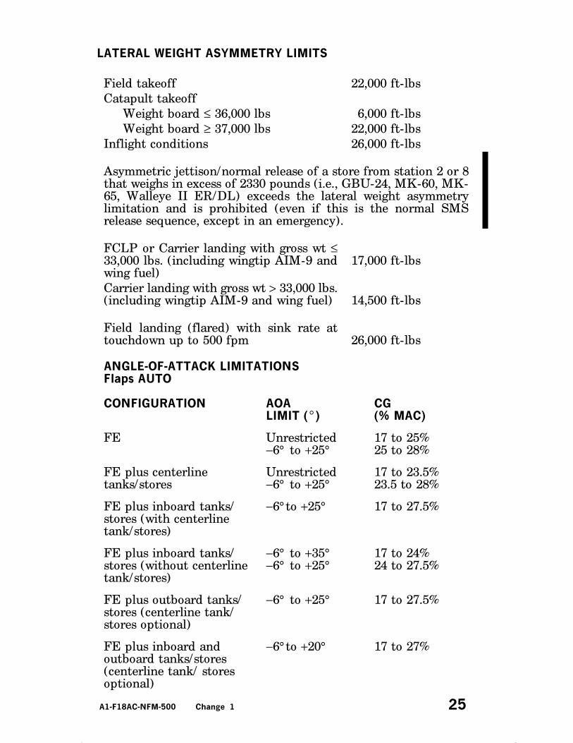
LATERAL WEIGHT ASYMMETRY LIMITS
Field takeoff 22,000 ft-lbs
Catapult takeoff
Weight board ≤ 36,000 lbs 6,000 ft-lbs
Weight board ≥ 37,000 lbs 22,000 ft-lbs
Inflight conditions 26,000 ft-lbs
Asymmetric jettison/normal release of a store from station 2 or 8that weighs in excess of 2330 pounds (i.e., GBU-24, MK-60, MK-65, Walleye II ER/DL) exceeds the lateral weight asymmetrylimitation and is prohibited (even if this is the normal SMSrelease sequence, except in an emergency).
FCLP or Carrier landing with gross wt ≤33,000 lbs. (including wingtip AIM-9 andwing fuel)
17,000 ft-lbs
Carrier landing with gross wt > 33,000 lbs.(including wingtip AIM-9 and wing fuel) 14,500 ft-lbs
Field landing (flared) with sink rate attouchdown up to 500 fpm 26,000 ft-lbs
ANGLE OF-ATTACK LIMITATIONSFlaps AUTO
CONFIGURATIONAOA
LIMIT (°)CG
(% MAC)
FE Unrestricted−6° to +25°
17 to 25%25 to 28%
FE plus centerlinetanks/stores
Unrestricted−6° to +25°
17 to 23.5%23.5 to 28%
FE plus inboard tanks/stores (with centerlinetank/stores)
−6° to +25° 17 to 27.5%
FE plus inboard tanks/stores (without centerlinetank/stores)
−6° to +35°−6° to +25°
17 to 24%24 to 27.5%
FE plus outboard tanks/stores (centerline tank/stores optional)
−6° to +25° 17 to 27.5%
FE plus inboard andoutboard tanks/stores(centerline tank/ storesoptional)
−6° to +20° 17 to 27%
A1-F18AC-NFM-500 Change 1 45

Lateral Weight Asymmetry AOA Limits
a. 6,000 to 12,000 ft-lbs asymmetry: −6° to +20° .b. 12,000 to 26,000 ft-lbs asymmetry: −6° to +12° .c. 22,000 to 26,000 ft-lbs asymmetry:
(1) Abrupt lateral stick inputs are prohibited.(2) Smooth inputs up to 1/2 stick for rolling maneuvers up to a
maximum of 180° bank angle change are authorized.(3) Rudder pedal inputs are authorized only as required to maintain
balanced flight (Slip indicator ball centered).
AOA Limits Due to Mach No. (F/A-18D)
MACH AOA LIMIT
0.7 to 0.8 −6° to +20°0.8 to 0.9 −6° to +15°above 0.9 −6° to +12°
Flaps HALF or FULL
a. 0° to +15° AOA (transitory excursions up to +20° are allowed duringcatapult launch only)
WEIGHT LIMITATIONS
The maximum allowable gross weights are:
Location Pounds
Field Takeoff 51,900
Field landing (flared) 39,000
FCLP/Touch-and-go/ Barricade 33,000
Carrier
Catapult 51,900Landing
UnrestrictedRestricted
33,00034,000
Arrestments above 33,000 pounds are subject to the following restrictions:
(1) Arresting gear - MK 7 MOD 3 Only(2) Glideslope - 3.5° Maximum(3) Recovery Head Wind (RHW) -
(a) 40 knots Minimum - Half flaps allowed(b) Less than 40 knots - Full flaps only
(4) Lateral Weight Asymmetry -14,500 ft-lb Maximum (External pylon stores, AIM-9 wing tips, andwing fuel)
(5) No MOVLAS recovery
A1-F18AC-NFM-500 46

ACCELERATION LIMITATIONS WITHOUT G LIMITER
Configuration Symmetrical Asymmetrical
Flaps HALFor FULL
+0.5 g to +2.0 g +0.5 g to +1.5 g
Flaps AUTO (32,357 poundsor less)-−3.0 g to +7.5 g
−1.0 g to +6.0 g
Gear Retractionand/orExtension
+0.5 g to +2.0 g +0.5 g to +1.5 g
CATAPULT THROTTLE SETTINGS
Weight Board (LBS) Engine Power
44,000 and belowMILMIL/MAXMAX
45,000 and up MAX
NOTE
MIL/MAX power setting is defined as stabilizing inMilitary power while in catapult tension, and selectingmaximum afterburner at holdback release.
A1-F18AC-NFM-500 47

A1-F18AC-NFM-500 48

Landing Approach Speed
AIRCRAFT REMARKSCONFIGURATION ENGINE(S): (2)F404-GE-402
U.S. STANDARD DAY, 1962
FLAPS AS NOTED
GEAR DOWN
SPEED BRAKE IN
NOTE
D C G AT 25% MAC. APPROACH SPEEDS INCREASE 1 KNOT FOR
EACH 2% THE C G IS FORWARD OF 25% MAC AND DECREASE 1
KNOT FOR EACH 2% THE C G IS AFT OF 25% MAC.
D INCREASE APPROACH SPEED BY 2 KNOTS IF WINGTIP AIM-9’S
ARE OFF
D INCREASE APPROACH SPEEDS BY 2 KNOTS IF EXTERNAL STORES
ON.
DATE: DECEMBER 1984
DATA BASIS: FLIGHT TEST LANDING APPROACH SPEED (KCAS)
LANDINGCONFIGURATION
FULL FLAPS 8.1°AOA (Normal
Landing)
HALF FLAPS8.1° AOA(NormalLanding)
GROSSWEIG
HT(LB)
24,000 117 126
25,000 119 129
26,000 121 131
27,000 124 134
28,000 126 136
29,000 128 139
30,000 130 141
31,000 133 144
32,000 135 146
33,000 137 148
34,000 139 151
35,000 141 153
36,000 143 155
37,000 145 157
38,000 147 159
39,000 149 161
A1-F18AC-NFM-500 58
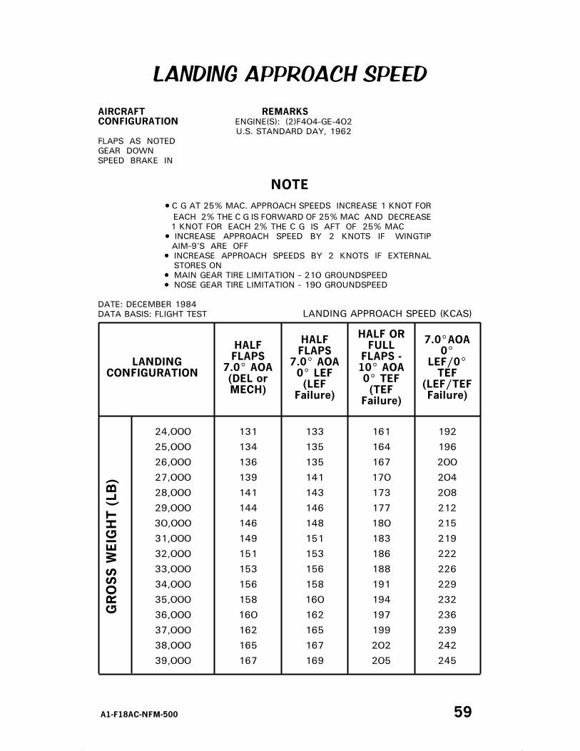
LANDING APPROACH SPEED
AIRCRAFT REMARKSCONFIGURATION ENGINE(S): (2)F404-GE-402
U.S. STANDARD DAY, 1962
FLAPS AS NOTED
GEAR DOWN
SPEED BRAKE IN
NOTE
D C G AT 25% MAC. APPROACH SPEEDS INCREASE 1 KNOT FOR
EACH 2% THE C G IS FORWARD OF 25% MAC AND DECREASE
1 KNOT FOR EACH 2% THE C G IS AFT OF 25% MAC
D INCREASE APPROACH SPEED BY 2 KNOTS IF WINGTIP
AIM-9’S ARE OFF
D INCREASE APPROACH SPEEDS BY 2 KNOTS IF EXTERNAL
STORES ON
D MAIN GEAR TIRE LIMITATION - 210 GROUNDSPEED
D NOSE GEAR TIRE LIMITATION - 190 GROUNDSPEED
DATE: DECEMBER 1984
DATA BASIS: FLIGHT TEST LANDING APPROACH SPEED (KCAS)
LANDINGCONFIGURATION
HALFFLAPS
7.0° AOA(DEL orMECH)
HALFFLAPS
7.0° AOA0° LEF(LEF
Failure)
HALF ORFULL
FLAPS -10° AOA0° TEF(TEF
Failure)
7.0°AOA0°
LEF/0°TEF
(LEF/TEFFailure)
GROSSWEIG
HT(LB)
24,000 131 133 161 192
25,000 134 135 164 196
26,000 136 135 167 200
27,000 139 141 170 204
28,000 141 143 173 208
29,000 144 146 177 212
30,000 146 148 180 215
31,000 149 151 183 219
32,000 151 153 186 222
33,000 153 156 188 226
34,000 156 158 191 229
35,000 158 160 194 232
36,000 160 162 197 236
37,000 162 165 199 239
38,000 165 167 202 242
39,000 167 169 205 245
A1-F18AC-NFM-500 59

A1-F18AC-NFM-500 61

A1-F18AC-NFM-500 62