eZeeNet Software Development Kit for RZ502 1.1 User's Guide
31
Doc. S-RZ502-451 v.1.2 August 2007 © 2007 MeshNetics eZeeNet Software Development Kit for RZ502 1.1 User’s Guide
-
Upload
khangminh22 -
Category
Documents
-
view
5 -
download
0
Transcript of eZeeNet Software Development Kit for RZ502 1.1 User's Guide

Doc. S-RZ502-451 v.1.2 August 2007 © 2007 MeshNetics
eZeeNet Software Development Kit for
RZ502 1.1 User’s Guide

E Z E E N E T S O F T W A R E D E V E L O P M E N T K I T F O R R Z 5 0 2 1 . 1 U S E R ’ S G U I D E
© 2007 MeshNetics. All rights reserved.
No part of the contents of this manual may be transmitted or reproduced in any form or by any means without the written permission of MeshNetics.
Disclaimer
MeshNetics believes that all information is correct and accurate at the time of issue. MeshNetics reserves the right to make changes to this product without prior notice. Please visit MeshNetics website for the latest available version.
MeshNetics does not assume any responsibility for the use of the described product or convey any license under its patent rights.
Trademarks
MeshNetics®, ZigBit, eZeeNet, ZigBeeNet, SensiLink, as well as MeshNetics and ZigBit logos are trademarks of LuxLabs Ltd., dba MeshNetics.
All other product names, trade names, trademarks, logos or service names are the property of their respective owners.
Development Support
Software customization services can be provided on terms and conditions mutually agreed by MeshNetics and end-user.
Contact Information
MeshNetics
9 Dmitrovskoye Shosse, Moscow 127434, Russia
Tel: +7 (495) 725 8125
Office hours: 8:00am – 5:00pm (Central European Time)
Fax: +7 (495) 725 8116
E-mail: [email protected]
www.meshnetics.com
© 2007 MeshNetics Page 2/31

E Z E E N E T S O F T W A R E D E V E L O P M E N T K I T F O R R Z 5 0 2 1 . 1 U S E R ’ S G U I D E
Table of Contents
1. Introduction...................................................... 6 2. eZeeNet Software Development Kit Overview...................................................................... 9 2.1. AVR RZ502/STK500/STK501 Set............................ 9
2.1.1. RZ502 Board................................................. 9 2.1.2. STK500 Board............................................. 10 2.1.3. STK501 Board............................................. 10
2.2. eZeeNet Software.................................................... 11 3. Getting Started ..............................................13 3.1. RZ502/STK500/STK501 Hardware Assembly....... 13 3.2. PC Software Installation .......................................... 14 4. WSN Demo Application ...............................16 4.1. Overview .................................................................. 16 4.2. Programming the Boards ........................................ 16 4.3. Using the Boards ..................................................... 18 4.4. WSN Monitor ........................................................... 20 4.5. Running WSN Demo............................................... 21
4.5.1. Starting WSN Demo on
RZ502/STK500/STK501 nodes.................. 21 4.5.2. Setting up node timeouts ............................ 22 4.5.3. Node Reset.................................................. 22 4.5.4. Changing Frequency Channels.................. 23
5. Using eZeeNet API........................................25 5.1. Sample Application Development........................... 25
5.1.1. Building WSN Demo ................................... 25 6. Troubleshooting............................................28 Appendices ...............................................................29
© 2007 MeshNetics Page 3/31

E Z E E N E T S O F T W A R E D E V E L O P M E N T K I T F O R R Z 5 0 2 1 . 1 U S E R ’ S G U I D E
List of Figures
Figure 1. The RZ502 Board with SMA stab antenna............ 9
Figure 2. The STK500 outlook (default setup) .................... 10
Figure 3. The STK501 outlook............................................. 10
Figure 4. eZeeNet Block Diagram....................................... 11
Figure 5. RZ502/STK500/STK501 configuration for WSN Demo application ................................................. 12
Figure 6. The RZ502/STK500/STK501 full hardware set assembly .............................................................. 14
Figure 7. Setting clock frequency ........................................ 17
Figure 8. WSN Monitor GUI................................................. 20
Figure 9. Example of file containing the node titles............. 21
Figure 10. WSN Monitor Tools/Settings menu ................... 22
Figure 11. Resetting the node ............................................. 22
Figure 12. Setting channel mask dialog box ....................... 23
Figure 13. Setting the channel mask using checkboxes .... 23
© 2007 MeshNetics Page 4/31
E Z E E N E T S O F T W A R E D E V E L O P M E N T K I T F O R R Z 5 0 2 1 . 1 U S E R ’ S G U I D E
© 2007 MeshNetics Page 5/31
List of Tables
Table 1. PORTD Cross-Board Bridging.............................. 13
Table 2. System requirements............................................. 14
Table 3. LED indication under WSN Demo ........................ 19
Table 4. Typical problems and solutions............................. 28
Table 5. The CD contents.................................................... 29

E Z E E N E T S O F T W A R E D E V E L O P M E N T K I T F O R R Z 5 0 2 1 . 1 U S E R ’ S G U I D E
1. Introduction
Intended Audience and Purpose
This document is intended for engineers and software developers evaluating MeshNetics eZeeNet Software with WSN Demo application and Atmel RZ502 Demonstration Kit.
Safety and Precautions
The product contains electronics, which are electrically sensitive. Please take necessary precautions when using such devices. Users are encouraged to follow common guidelines to avoid electrostatics by using proper grounding, and so on.
Any modifications of the hardware, its components or improper use of the product can cause an uncontrolled violation of the in-band or out-band radiation levels. It can result in progressing violation of emission level limits, thus causing harmful interference.
Please check your local regulations to make sure that the product’s electromagnetic radiation level specified in this document complies.
Precautions
The product radiates power in the microwave band. Although the levels are considered to be low (less than 2 mW), it is reasonable to protect the operating personnel from possible harmful impact of the electromagnetic field. When the parts of the product are turned on, an operator should avoid touching the PCB antenna and the board itself. The recommended distance between an operator and antenna should be more than 20 centimeters.
The AC/DC adapter included into the product contains high voltage circuits inside. General precautions should be taken, like checking the power cord before use if boards are mains powered.
The RZ502 Demonstration Kit contains fragile components. Please handle with care.
Related documents
[1] ATAVRRZ502 Accessory Kit. User’s Guide. Atmel Doc. 8051
http://www.atmel.com/dyn/resources/prod_documents/doc8051.pdf
[2] AVR STK 500. User’s Guide. Atmel Doc.. 1925.
http://www.atmel.com/dyn/resources/prod_documents/doc1925.pdf
[3] AVR STK 501. User’s Guide. Atmel Doc. 2491.
http://www.atmel.com/dyn/resources/prod_documents/DOC2491.pdf
[4] eZeeNet™ IEEE802.15.4/ZigBee Software. Product Datasheet. MeshNetics Doc.
M-251~02
[5] eZeeNet™ Software 1.7. eZeeNet™ API. Reference Manual. MeshNetics Doc.
P-EZN-452~02
[6] ZigBee Document 053474r14, November 03, 2006
[7] IEEE Std 802.15.4-2003 IEEE Standard for Information technology – Part 15.4
Wireless Medium Access Control (MAC) and Physical Layer (PHY) Specifications
for Low-Rate Wireless Personal Area Networks (LR-WPANs)
[8] AVR Studio. User Guide.
http://www.atmel.com/dyn/resources/prod_documents/doc2510.pdf.
© 2007 MeshNetics Page 6/31

E Z E E N E T S O F T W A R E D E V E L O P M E N T K I T F O R R Z 5 0 2 1 . 1 U S E R ’ S G U I D E
[9] JTAGICE mkII User Guide.
http://www.atmel.com/dyn/resources/prod_documents/doc2562.pdf
[10] 8-bit AVR Microcontroller with 64K/128K/256K Bytes in-System Programmable
Flash. ATMEL Preliminary Doc. 2549J-AVR-09/06.
http://www.atmel.com/dyn/resources/prod_documents/doc2549.pdf
Abbreviations and Acronyms
ADC Analog to Digital Converter
API Application Programming Interface
Channel Mask Channel mask is a number that defines the set of working channels.
Coordinator Within ZigBee networks, the ZigBee coordinator is responsible for starting the network and for choosing certain key network parameters, but the network may be extended through the use of ZigBee router.
EEPROM Electrically Erasable Programmable Read-Only Memory
End device In ZigBee networks, the ZigBee end device provides sensor data sent to a router and is requesting a router periodically in duty cycle. End device is subjected to power management and it stays in sleeping mode most of time.
ESD Electrostatic Discharge
GUI Graphical User Interface
HAL Hardware Abstraction Layer
IDE Integrated Development Environment
ISP In-System Programming
JTAG Digital interface for debugging of embedded devices. Also known as IEEE 1149.1 standard interface
LCD Liquid Crystal Display
LED Light Emitting Diode
LQI Link Quality Indicator
MAC Medium Access Control layer
MCU Microcontroller Unit
NWK Network layer
PAN ID Personal Area Network Identifier. In ZigBee, it is 16-bit number which must be unique within multiple networks working on the same frequency channel
PCB Printed Circuit Board
PHY Physical layer
RF Radio Frequency
© 2007 MeshNetics Page 7/31

E Z E E N E T S O F T W A R E D E V E L O P M E N T K I T F O R R Z 5 0 2 1 . 1 U S E R ’ S G U I D E
Router In the ZigBee network conception, routers transfer data and control messages through the network using a hierarchical routing strategy. The ZigBee coordinator is also responsible for routing.
RS-232 Serial binary data interconnection interface, which is commonly used in computer serial ports
RSSI Received Signal Strength Indicator
TQFP Thin Quad Flat Pack
USB Universal Serial Bus
WSN Wireless Sensor Network
ZigBee Wireless networking standard targeted at low-power sensor applications
ZIF Zero Insertion Force socket
© 2007 MeshNetics Page 8/31
E Z E E N E T S O F T W A R E D E V E L O P M E N T K I T F O R R Z 5 0 2 1 . 1 U S E R ’ S G U I D E
2. eZeeNet Software Development Kit Overview
eZeeNet Software Development Kit is a flexible tool designed to evaluate the Atmel’s RZ502/STK500/STK501 hardware platform (ATAVRRZ502 Demonstration Kit [1], [2], [3]) and to develop wireless networks applications based on the MeshNetics’ eZeeNet Software.
RZ502/STK500/STK501 hardware platform features AT86RF230 Radio Transceiver and AVR ATmega1281V microcontroller. Programming the STK500/STK501 boards with WSN custom applications based on eZeeNet Software [4] enables the kit devices to become the nodes of a ZigBee/ 802.15.4 wireless network [6], [7]. Any of such devices can be configured to operate as a network coordinator, a router or an end device, with downloading the corresponding firmware image.
eZeeNet Software Development Kit for RZ502 consists of the following parts:
1. Atmel’s AVR RZ502/STK500/STK501 set [1] including:
• RZ502 Board • STK500 Board • STK501 Board • accessories
2. eZeeNet Software & Documentation.
2.1. AVR RZ502/STK500/STK501 Set
2.1.1. RZ502 Board
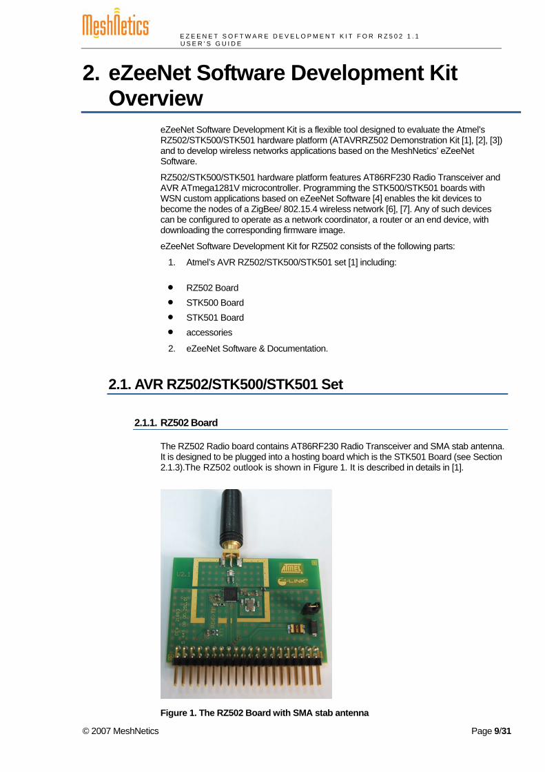
The RZ502 Radio board contains AT86RF230 Radio Transceiver and SMA stab antenna. It is designed to be plugged into a hosting board which is the STK501 Board (see Section 2.1.3).The RZ502 outlook is shown in Figure 1. It is described in details in [1].
Figure 1. The RZ502 Board with SMA stab antenna
© 2007 MeshNetics Page 9/31
E Z E E N E T S O F T W A R E D E V E L O P M E N T K I T F O R R Z 5 0 2 1 . 1 U S E R ’ S G U I D E
2.1.2. STK500 Board
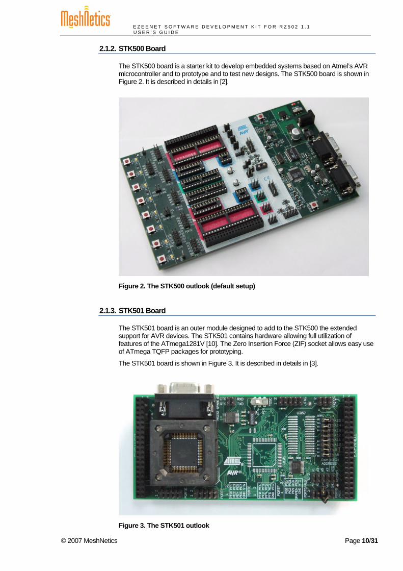
The STK500 board is a starter kit to develop embedded systems based on Atmel’s AVR microcontroller and to prototype and to test new designs. The STK500 board is shown in Figure 2. It is described in details in [2].
Figure 2. The STK500 outlook (default setup)
2.1.3. STK501 Board
The STK501 board is an outer module designed to add to the STK500 the extended support for AVR devices. The STK501 contains hardware allowing full utilization of features of the ATmega1281V [10]. The Zero Insertion Force (ZIF) socket allows easy use of ATmega TQFP packages for prototyping.
The STK501 board is shown in Figure 3. It is described in details in [3].
Figure 3. The STK501 outlook
© 2007 MeshNetics Page 10/31

E Z E E N E T S O F T W A R E D E V E L O P M E N T K I T F O R R Z 5 0 2 1 . 1 U S E R ’ S G U I D E
2.2. eZeeNet Software eZeeNet Software from MeshNetics is a robust IEEE802.15.4/ZigBee software that organizes embedded devices into a self-healing, self-organizing mesh network. It is specifically tailored to provide easy-to-use networking to sensing, control, monitoring and data acquisition applications. It provides multi-point networking, with a routing mechanism that optimizes the network traffic and reduces power consumption. In addition, eZeeNet conforms to ZigBee specification.
eZeeNet software offers a user-friendly API for network and smart power management, including data exchange, network formation/node join, PAN ID management, channel selection, TX power control etc. eZeeNet’s HAL enables a wide range of software interfaces for standard peripherals attached to supported hardware platforms. eZeeNet’s Framework layer drastically simplifies development by offering a convenient, high-level API.
The structure of eZeeNet software stack (see Figure 4) is explored in [4].
eZeeNet APIs combines programming interfaces of eZeeNet network stack, eZeeNet Framework layer and HAL. These APIs are highlighted in Section 5 of this document and fully described in [5].
SerialNetOEM extensions
Platform- specific drivers
eZeeNet Stack Support
HAL (drivers)
User application
Board with external peripherals
External sensors
Host interface
User’s software
Task scheduler
EEPROM management
eZeeNet software
hardware
eZeeNet Stack
MACNWK
APS/ZDO
eZeeNet Framework/API
Figure 4. eZeeNet Block Diagram
On Atmel’s RZ502 platform, eZeeNet Software stack features and performance can be evaluated by means of WSN Demo application combined with WSN Monitor. The applications are delivered as a set of embedded firmware images, supporting functions for coordinator, router and end device, and a special PC application providing GUI functionality. See the description and the usage information on WSN Demo in Section 4.
© 2007 MeshNetics Page 11/31
E Z E E N E T S O F T W A R E D E V E L O P M E N T K I T F O R R Z 5 0 2 1 . 1 U S E R ’ S G U I D E
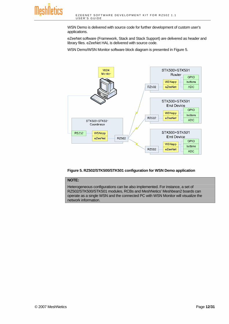
WSN Demo is delivered with source code for further development of custom user’s applications.
eZeeNet software (Framework, Stack and Stack Support) are delivered as header and library files. eZeeNet HAL is delivered with source code.
WSN Demo/WSN Monitor software block diagram is presented in Figure 5.
Figure 5. RZ502/STK500/STK501 configuration for WSN Demo application
NOTE:
Heterogeneous configurations can be also implemented. For instance, a set of RZ502/STK500/STK501 modules, RCBs and MeshNetics’ Meshbean2 boards can operate as a single WSN and the connected PC with WSN Monitor will visualize the network information.
© 2007 MeshNetics Page 12/31

E Z E E N E T S O F T W A R E D E V E L O P M E N T K I T F O R R Z 5 0 2 1 . 1 U S E R ’ S G U I D E
3. Getting Started Before running WSN Demo application the boards should be assembled and powered on, following the instructions given in Section 3.1 and Section 4.2. Programming the boards is described in Section 4.2.
To run WSN Demo, see instructions in Section 4. In case of a problem refer to Section 6.
3.1. RZ502/STK500/STK501 Hardware Assembly To assemble each of RZ502/STK500/STK501 sets for safe operation do the following steps. The detailed information on assembling the module is given in [1]. Strictly follow the manufacturer’s instructions.
1. To fit 3V operating voltage correctly, configure the STK500 board, placing jumpers
on the following headers: VTARGET, AREF, RESET, BSEL2.
2. Connect a serial cable to the connector marked RS232CTRL on the STK500 and to
a COM port on the PC.
3. Link AC/DC power adaptor to power connector of the STK500 board. AC/DC
power adaptor should comply with the STK500 system requirements given in [2].
Apply voltage by moving power switch toward the edge of the board.
4. Start AVR Studio. From the Tools menu, select Program AVR and Connect….
Select ‘STK500 or AVRISP’ as platform and then press Connect…. Verify that
a window named STK500 appears. Open the Board tab (see Figure 7 below).
Adjust the VTarget voltage and ARef voltage to 3 Volts. Press the Write
Voltages button. Close the STK500 window.
IMPORTANT NOTE:
To prevent the damage of AT86RF230 radio transceiver the STK500 board must be obligatory configured, using AVR Studio.
5. Preparing the STK500 board, make sure that LEDS connector is bridged to PORTC
connector with cable as shown in Figure 6.
6. Install an ATmega1281V on the STK501.
7. Attach the STK501 extension board to STK500 keeping them both out of power.
Attaching the STK501 board, the PORTD pins on STK500 should be bridged to the
following pins on STK501 (see Table 1):
Table 1. PORTD Cross-Board Bridging
STK500 PORTD Pins STK501 Pins
PD2 RXD
PD3 TXD
© 2007 MeshNetics Page 13/31

E Z E E N E T S O F T W A R E D E V E L O P M E N T K I T F O R R Z 5 0 2 1 . 1 U S E R ’ S G U I D E
8. Mount the RZ502 radio board onto the STK501 board using its EXPAND1 header
and matching pin 1 on STK501 board (see Figure 6) with pin1 on RZ502 which pad
is shaped squared.
9. Power on the STK500 board linking AC/DC power adaptor to power connector.
Final assembly is shown for RZ502/STK500/STK501 set in Figure 6.
Figure 6. The RZ502/STK500/STK501 full hardware set assembly
3.2. PC Software Installation Before using the Kit with RZ502/STK500/STK501 sets, particularly before downloading firmware images to this hardware, and before running the applications, user should become aware of the minimum system requirements (see Table 2).
Table 2. System requirements
Parameter Value Note
Hardware
PC/CPU Intel Pentium III or higher, 800 MHz
PC/RAM 128 Mbytes
© 2007 MeshNetics Page 14/31

E Z E E N E T S O F T W A R E D E V E L O P M E N T K I T F O R R Z 5 0 2 1 . 1 U S E R ’ S G U I D E
Parameter Value Note
PC/Video 1024x768, SVGA
PC/Hard disk free space 50 MBytes
Software
Operating system Windows2000/XP
IDE AVR Studio 4.12 + Service Pack + WinAVR
needed to download firmware through ISP (or JTAG) into a board (see Section 4.2) and to build user’s custom applications
Java machine Java Runtime Environment JRE 5.0 Update 8 (version 1.5.0)
needed to run the WSN Monitor (see Section 4.4)
WSN Monitor installation package
needed to install the WSN Monitor (see Section 4.4)
To make serial connection with PC, use RS-232 connector for configuring the STK500 board (see Section 3.1).
Current version of the AVR Studio [8] with Service Pack can be freely downloaded from the Atmel’s website (http://www.atmel.com). Simply launch the downloaded installer programs and follow set up instructions.
Running WSN Monitor requires Java machine, version not older than 1.5.0 (build 1.5.0_08-b03). Download Java Runtime Environment (JRE) 5.0 Update 8 from Sun’s site (http://java.sun.com/javase/downloads/index.jsp) and follow the upcoming installation instructions.
After you get Java machine on your PC, run the WSN Monitor installer package taken from the MeshNetics’ Distribution CD (see Appendix A) and follow the related instructions. There may be other Java instances occasionally installed on your computer. To avoid confusion, edit start.bat file in the directory containing the WSN Monitor so that to provide full path to the Java 1.5.0 executable file and specify its file name extension (.exe) explicitly.
© 2007 MeshNetics Page 15/31

E Z E E N E T S O F T W A R E D E V E L O P M E N T K I T F O R R Z 5 0 2 1 . 1 U S E R ’ S G U I D E
4. WSN Demo Application
4.1. Overview WSN demo application is intended to evaluate operation of Atmel’s hardware as a part of a full-featured ZigBee network.
Thanks to the WSN Demo application embedded, the board modules are organized into a set of nodes constituting a wireless network. In absence of the on-board sensors for end devices and routers, the ADC0, ADC1 and ADC2 readings are used there in duty circle which are sent in packets to coordinator and which are displayed on WSN Monitor panes as temperature, light and battery level measurements ranged from 0 to 1.1.
End device is mostly sleeping, consuming very low power, and wakes up shortly for this activity each 10 seconds. Router sends data each 1 second. The coordinator transmits the received packets, along with its own sensor data, to the GUI (WSN Monitor) application, using UART.
Maximum network size is not limited by WSN Demo. In real time, WSN Monitor visualizes the network topology in a tree form. It also displays the node parameters like addresses, node sensor information and the node link quality data.
Measured in dBm, RSSI reflects the link’s current condition. With the resolution not better than 3 dBm, this is not a very accurate measurement. LQI is a certain number defined within the 0...255 range to measure the link quality. Larger values mean better link, while values close to zero indicate poor communication conditions.
Using WSN Monitor controls you can change the network channel mask, node timeouts and you can reset any node remotely.
The application is implemented using the eZeeNet API (see Section 5).
In regard to WSN Demo, using the boards is described in Section 4.3. GUI is described in Section 4.4. Operation instructions are given in Section 4.5.
4.2. Programming the Boards Before programming the device the STK500 and STK501 boards should be assembled as described in Section 3.1. Make sure that all software is installed as described in Section 3.2.
IMPORTANT NOTE:
To prevent damaging of RZ502 it is strictly recommended to detach the RZ502 board from the STK501 board before programming.
Two options are available to program the device: either in In-System Programming (ISP) mode or in JTAG mode. ISP mode is preferable for it does not require using JTAG programmer.
In order to program the device using ISP mode connect the 6pin cable between the ISP6PIN connector on the STK500 board and the ISP connector on the STK501 which is denoted by SPROG mark. The connectors are shown in Figure 6. Red wire should correspond to pin 6 at both connector sides. Make sure that RS232 port on PC is connected properly to CTRL port on STK500. Now, the device can be programmed in ISP mode using AVR Studio Software. Consider that the programming process will take substantial time. See [2] for additional information on how to use the STK500 front-end software for ISP programming.
It is important that ISP frequency should be set to 115.8 kHz as shown in Figure 7.
© 2007 MeshNetics Page 16/31

E Z E E N E T S O F T W A R E D E V E L O P M E N T K I T F O R R Z 5 0 2 1 . 1 U S E R ’ S G U I D E
Figure 7. Setting clock frequency
To program the node as coordinator, router or end device use the corresponding *.hex image files found in ./Demo/WSNDemo/ subdirectory (see Table 5 for notation). Make sure all your boards are programmed with different images and no image file is used twice.
NOTE:
After having been programmed, the module gets the unique MAC address which is encoded within the image file downloaded. This MAC address is represented by low-order digit closing the corresponding filename.
For instance, the following set may be used to build a network consisting of coordinator, routers and end device:
wsndemo_stk_c_1.hex wsndemo_stk_r_2.hex wsndemo_stk_e_5.hex
Check ON the following options in Fuses Tab before downloading the images through ISP:
Brown-out detection disabled; [BODLEVEL=111] JTAG Interface Enabled; [JTAGEN=0] Serial program downloading (SPI) enabled; [SPIEN=0]
© 2007 MeshNetics Page 17/31

E Z E E N E T S O F T W A R E D E V E L O P M E N T K I T F O R R Z 5 0 2 1 . 1 U S E R ’ S G U I D E
Boot Flash section size=1024 words Boot start address=$FE00;[BOOTSZ=10] Divide clock by 8 internally; [CKDIV8=0] Int. RC Osc.; Start-up time: 6 CK + 65 ms; [CKSEL=0010 SUT=01]
Uncheck the rest of options. Make sure the following hex value string appears at the bottom of Fuses Tab: 0xFF, 0x9D, 0x62.
NOTE:
Advanced user may uncheck the Divide clock by 8 internally; [CKDIV8=0] fuse to set ISP frequency to 1.845 MHz before programming the device. Nevertheless, this fuse should be ultimately checked on again to ensure running an application properly.
Alternatively, to program the device by JTAG link an external JTAG emulator, for example JTAGICE mkII from Atmel1 [9], with the STK501onboard JTAG connector (see Figure 6). Start downloading process following instructions from [8] and [9]. The same fuse bits should be set as specified above for ISP mode. In this case the fuse bit controlling ISP frequency does not matter.
4.3. Using the Boards Before using RZ502/STK500/STK501 sets as WSN nodes with WSN Demo, assemble each of the sets as instructed in Section 3.1.
WSN Demo is designed so that the default channel mask is encoded within firmware image and it is loaded to the node’s flash memory. The default channel mask is defined within WSN Demo firmware and it is set to 0x01000000, which means using channel 0x18. At each regular node startup, the current channel mask is read from EEPROM.
IMPORTANT NOTE:
To store in EEPROM the default channel mask loaded to STK501 (ATmega1281V) flash memory during programming, the initialization of the node for the first time must be performed as follows.
Before powering STK500, make SWITCHES connector (see Figure 6) and PORTA connector bridged with the cable. Press and hold the SW0 onboard button first. Turn power on the STK500 with holding the button pressed for at least 1 second. The LED1 will get flashing 3 times. Next LED0, LED1 and LED2 will start blinking for 2 sec to indicate accepting the channel mask in EEPROM.
Starting the WSN Demo, do the following:
1. Connect the coordinator node to the PC using RS-232 port on STK-501
2. Power on the coordinator node
3. Power on the rest of the nodes.
NOTE:
When running WSN Demo, channel mask can be changed anytime later with sending the command from the WSN Monitor (see Section 4.5.4). Channel mask recently issued from WSN Monitor and received on a node is stored in its EEPROM permanently after getting power on and off. To restore the default channel mask in EEPROM repeat a node reinitializing procedure described above in this section.
1 Another JTAG programmer may be also used but it should be compatible with the Atmel 1281 MCU.
© 2007 MeshNetics Page 18/31

E Z E E N E T S O F T W A R E D E V E L O P M E N T K I T F O R R Z 5 0 2 1 . 1 U S E R ’ S G U I D E
Coordinator organizes the wireless network automatically. Upon starting, any node informs the network on its role. At that moment LED0, LED1 and LED2 are flashing once on router, they are flashing twice on end device and they are flashing three times on coordinator.
After joining the network, a node starts sending data to the coordinator which is indicated by LEDs.
WSN activity is observed in two ways:
• controlling the on-board LEDs (see LED indication described in Table 3) • controlling the network information through the WSN Monitor installed on PC.
Normally, coordinator organizes the wireless network automatically. The nodes start sending data to the coordinator which is indicated by LEDs.
Table 3. LED indication under WSN Demo
LED state
Node State LED2 LED1 LED0
Network searching blinking OFF OFF
Joined to network ON
Message receiving ON flashing
Message transmitting ON flashing
Changing channel mask blinking blinking blinking
Sleeping (for end device only) OFF OFF OFF
If you turn on the power on the coordinator, it will switch to the active state, even if no child nodes are present. This is normal, it means that the coordinator is ready and child nodes can join the network with coordinator’s PAN ID.
By default, coordinator uses predefined PAN ID valued as A152, which is recognized by all routers. Changing PAN ID is not allowed.
NOTES:
If coordinator is not present or it is not turned on, the routers will stay in the network search mode. In this mode, routers scan the selected frequency channels continuously to search for a network with the selected PAN ID.
In rare cases, if radio channel is busy on the selected frequency channels the coordinator node will stay in the network searching mode. If this happened, you should change the frequency channel by means of changing channel mask using WSN Monitor.
STK501 board has PortF connector installed (see Section 3.1). Pins 1, 2 and 3 of this port are bridged, respectively, to ADC0, ADC1 and ADC2 pin of the AVR ATmega1281V microcontroller. Use PortF connector to attach your customized sensors.
ADC0, ADC1 and ADC2 pins are processed by WSN Demo. Node sensor table in WSN Monitor screen (see Figure 8) displays current values for ADC0, ADC1 and ADC2 input voltage (ranged from 0 to 1,1V). ADC inputs may contain arbitrary data unless they are connected to sensors.
© 2007 MeshNetics Page 19/31

E Z E E N E T S O F T W A R E D E V E L O P M E N T K I T F O R R Z 5 0 2 1 . 1 U S E R ’ S G U I D E
IMPORTANT NOTE:
The input voltage must not exceed 1,1V for ADC0..ADC3! To avoid damaging the module circuitry your sensor design parameters must correspond to this strict requirement. Refer to the board schematics for details.
4.4. WSN Monitor WSN Monitor is a PC-based GUI application for WSN Demo that serves to display WSN topology and other information about WSN network. See WSN Monitor screen in Figure 8. It contains the Network Topology Pane, Node Data Pane and Toolbars.
Network Topology Pane displays in real time the network tree. That helps to control the network formation and evolution while the nodes join, send data or leave. The Network Topology pane updates automatically during the network nodes are discovered and joined through coordinator. The nodes which are denoted with their names are presented in icons with the node data tips. The nodes are organized into the tree connected via parent/child links tipped with RSSI and LQI values.
Node Data Pane displays node sensor data coming from ADC0, ADC1 and ADC2 interfaces (see Section 4.3). They are presented in graphs and table. Node parameters are presented in table. Node Data Pane includes a pull-down Sensor Selection menu for sensor data to display. Use the button on the Sensor Control Toolbar to display the required types of sensor data.
Use text menu upside and toolbars controlling visualization.
Figure 8. WSN Monitor GUI
Be aware of the system requirements before use. The WSN Monitor should be installed according to Section 3.2.
© 2007 MeshNetics Page 20/31
E Z E E N E T S O F T W A R E D E V E L O P M E N T K I T F O R R Z 5 0 2 1 . 1 U S E R ’ S G U I D E
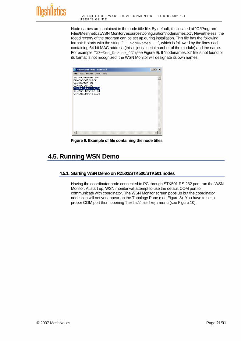
Node names are contained in the node title file. By default, it is located at "C:\Program Files\Meshnetics\WSN Monitor\resources\configuration\nodenames.txt”. Nevertheless, the root directory of the program can be set up during installation. This file has the following format: it starts with the string “-- NodeNames --”, which is followed by the lines each containing 64-bit MAC address (this is just a serial number of the module) and the name. For example: “03=End_Device_03” (see Figure 9). If “nodenames.txt” file is not found or its format is not recognized, the WSN Monitor will designate its own names.
Figure 9. Example of file containing the node titles
4.5. Running WSN Demo
4.5.1. Starting WSN Demo on RZ502/STK500/STK501 nodes
Having the coordinator node connected to PC through STK501 RS-232 port, run the WSN Monitor. At start up, WSN monitor will attempt to use the default COM port to communicate with coordinator. The WSN Monitor screen pops up but the coordinator node icon will not yet appear on the Topology Pane (see Figure 8). You have to set a proper COM port then, opening Tools/Settings menu (see Figure 10).
© 2007 MeshNetics Page 21/31
E Z E E N E T S O F T W A R E D E V E L O P M E N T K I T F O R R Z 5 0 2 1 . 1 U S E R ’ S G U I D E
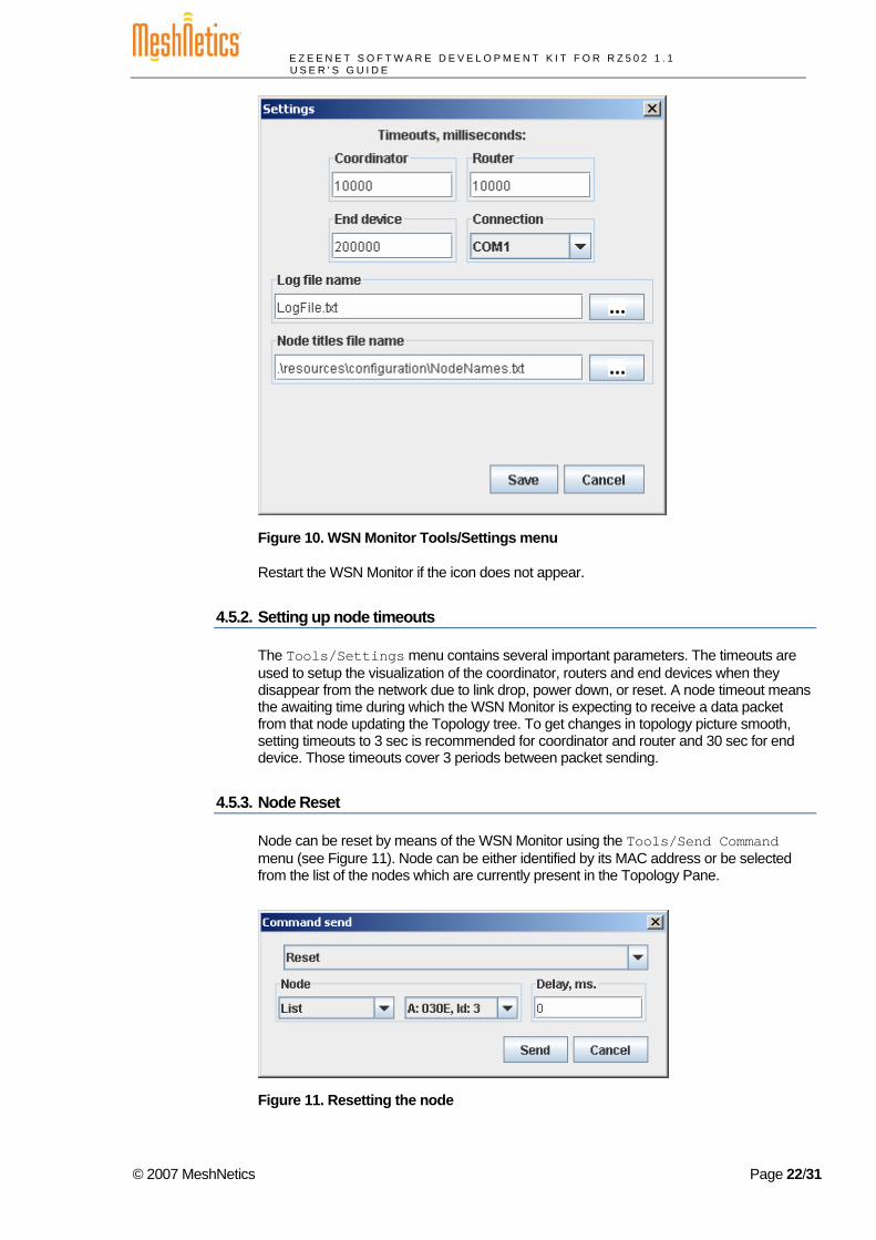
Figure 10. WSN Monitor Tools/Settings menu
Restart the WSN Monitor if the icon does not appear.
4.5.2. Setting up node timeouts
The Tools/Settings menu contains several important parameters. The timeouts are used to setup the visualization of the coordinator, routers and end devices when they disappear from the network due to link drop, power down, or reset. A node timeout means the awaiting time during which the WSN Monitor is expecting to receive a data packet from that node updating the Topology tree. To get changes in topology picture smooth, setting timeouts to 3 sec is recommended for coordinator and router and 30 sec for end device. Those timeouts cover 3 periods between packet sending.
4.5.3. Node Reset
Node can be reset by means of the WSN Monitor using the Tools/Send Command menu (see Figure 11). Node can be either identified by its MAC address or be selected from the list of the nodes which are currently present in the Topology Pane.
Figure 11. Resetting the node
© 2007 MeshNetics Page 22/31
E Z E E N E T S O F T W A R E D E V E L O P M E N T K I T F O R R Z 5 0 2 1 . 1 U S E R ’ S G U I D E
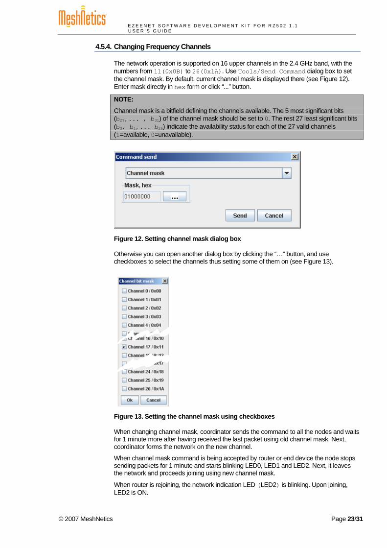
4.5.4. Changing Frequency Channels
The network operation is supported on 16 upper channels in the 2.4 GHz band, with the numbers from 11(0x0B) to 26(0x1A). Use Tools/Send Command dialog box to set the channel mask. By default, current channel mask is displayed there (see Figure 12). Enter mask directly in hex form or click “...” button.
NOTE:
Channel mask is a bitfield defining the channels available. The 5 most significant bits (b27,... , b31) of the channel mask should be set to 0. The rest 27 least significant bits (b0, b1,... b26) indicate the availability status for each of the 27 valid channels (1=available, 0=unavailable).
Figure 12. Setting channel mask dialog box
Otherwise you can open another dialog box by clicking the “…” button, and use checkboxes to select the channels thus setting some of them on (see Figure 13).
Figure 13. Setting the channel mask using checkboxes
When changing channel mask, coordinator sends the command to all the nodes and waits for 1 minute more after having received the last packet using old channel mask. Next, coordinator forms the network on the new channel.
When channel mask command is being accepted by router or end device the node stops sending packets for 1 minute and starts blinking LED0, LED1 and LED2. Next, it leaves the network and proceeds joining using new channel mask.
When router is rejoining, the network indication LED (LED2) is blinking. Upon joining, LED2 is ON.
© 2007 MeshNetics Page 23/31

E Z E E N E T S O F T W A R E D E V E L O P M E N T K I T F O R R Z 5 0 2 1 . 1 U S E R ’ S G U I D E
When end device is rejoining, the network indication LED (LED2) is blinking. Upon joining, LED2 turns ON. LED0 flashes shortly to indicate sending a packet, LED1 flashes shortly to indicate receiving an acknowledgement. Next, the all LEDs turn OFF when end device is falling to sleep.
When channel mask is being changed, the topology screen may not display real topology tree. After changing channel mask the network topology tree is actualized.
© 2007 MeshNetics Page 24/31
E Z E E N E T S O F T W A R E D E V E L O P M E N T K I T F O R R Z 5 0 2 1 . 1 U S E R ’ S G U I D E
5. Using eZeeNet API eZeeNet Software allows a user to develop custom applications. Full functionality of eZeeNet Software becomes available when employing eZeeNet API. This includes configuration of:
• WSN network common parameters (PAN ID, channel mask) • Node role (being coordinator, router or end device) • Node MAC address • RF output power.
User’s application is enabled to control a WSN with respect to: • Network formation (through coordinator node) • Node join/leaving • Data transmission over the WSN network • Data transportation through UART interface for further data acquisition • Node power management • Accessing node peripherals etc.
The extensive description of eZeeNet API can be found in [5]. That document contains detailed instructions on how to build custom applications. It includes a sample application in source code.
5.1. Sample Application Development WSN Demo application is delivered with the Kit in source code.
Operation details are presented in Section 4. The present section introduces a user to the development of custom applications based on the delivered code. The instructions on how to compile it and how to run software are given in Section 5.1.1. To start, the following tools are necessary.
We recommend using Atmel’s AVR Studio [8]. This Integrated Development Environment (IDE) provides editing a source code, compiling, linking object modules with libraries, debugging, making executable file automatically, and more. AVR Studio can be integrated with WinAVR, a suite of software development tools for the Atmel AVR series of RISC microprocessors hosted on the Windows platform [10]. Setting channel mask dialog box . WinAVR contains a set of utilities including AVR GCC compiler, linker, automatic Makefile generator, system libraries etc. Installation of the AVR GCC plug-in lets those tools working automatically in AVR Studio. GCC compiler is designed to be executed on the Windows platform, and is configured to compile C or C++ codes.
Current version of the AVR Studio with Service Pack may be downloaded freely from Atmel’s website (http://www.atmel.com). Simply launch the downloaded installation programs and follow the setup instructions. The WinAVR suite containing the development tools can be downloaded from http://sourceforge.net/projects/winavr. To install WinAVR follow the setup instructions.
5.1.1. Building WSN Demo
WSN Demo application is developed on top of the standard eZeeNet Software.
The source code for WSN Demo application can be found in ./API/SampleApplication/WSNDemo subdirectory (see Appendix A).
eZeeNet Software (including Framework, Stack and Stack Support) is delivered as the header and the library files. They can be found, correspondingly, in:
© 2007 MeshNetics Page 25/31
E Z E E N E T S O F T W A R E D E V E L O P M E N T K I T F O R R Z 5 0 2 1 . 1 U S E R ’ S G U I D E
./API/Framework
./API/Stack
./API/StackSupport.
eZeeNet HAL is delivered along with source code. It can be found in
./API/HAL/HAL_R6
./API/HAL/HAL_STK500
Network parameters for WSN Demo can be defined in Makefile, as shown below:
# Network parameters DEFINES = \ WSN_DEFAULT_CHANNEL_MASK=0x1000000 \ ADE_SOFTWARE_VERSION=0x01070000 \ DEFAULT_PAN_ID=0xD170 \ NWK_MAX_END_DEVICES=2 \ NWK_MAX_ROUTER_NEIB_NUMBER=2 \ NWK_MAX_DEPTH=4 \ MAX_PAN_DESCRIPTORS=5 \
WSN_DEFAULT_CHANNEL_MASK string defines WSN channel mask. 0x1000000 specifies the channel numbered as 0x18.
ADE_SOFTWARE_VERSION string defines the version number for the software.
DEFAULT_PAN_ID string defines WSN’s PAN ID.
NWK_MAX_END_DEVICES is the maximum number of end devices that can be associated with coordinator or router.
MAX_ROUTER_NEIB_NUMBER is the maximum number of routers that can be associated with coordinator or router.
NWK_MAX_DEPTH is the maximum depth of network.
MAX_PAN_DESCRIPTORS is maximum number of PAN descriptors used during network scanning; it is recommended be equal 3 at least.
Along with setting the network parameters, a unique MAC address (IEEE address) should be set for each WSN node. MAC address can be defined in Makefile for loading to a node along with the application or it can be specified in command line executing the compilation.
Varying the IEEEADDR value in Makefile you can prepare the image files for individual nodes:
#default IEEE address IEEEADDR = 1
NOTE:
Do not set zero MAC address for a node because it would not be able to join a network!
To compile WSN demo application for each node type use make utility or open AVR Studio.
Taking the first option, execute the following commands in command line:
make clean make
© 2007 MeshNetics Page 26/31
E Z E E N E T S O F T W A R E D E V E L O P M E N T K I T F O R R Z 5 0 2 1 . 1 U S E R ’ S G U I D E
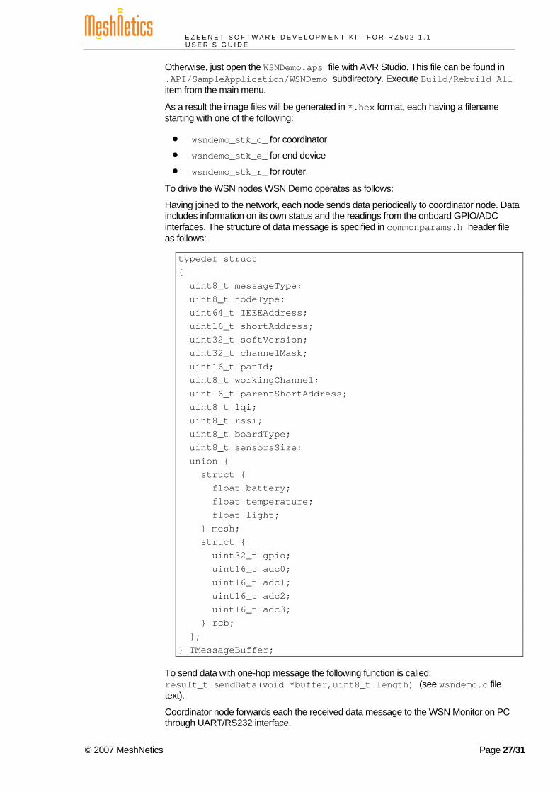
Otherwise, just open the WSNDemo.aps file with AVR Studio. This file can be found in .API/SampleApplication/WSNDemo subdirectory. Execute Build/Rebuild All item from the main menu.
As a result the image files will be generated in *.hex format, each having a filename starting with one of the following:
• wsndemo_stk_c_ for coordinator
• wsndemo_stk_e_ for end device
• wsndemo_stk_r_ for router.
To drive the WSN nodes WSN Demo operates as follows:
Having joined to the network, each node sends data periodically to coordinator node. Data includes information on its own status and the readings from the onboard GPIO/ADC interfaces. The structure of data message is specified in commonparams.h header file as follows:
typedef struct { uint8_t messageType; uint8_t nodeType; uint64_t IEEEAddress; uint16_t shortAddress; uint32_t softVersion; uint32_t channelMask; uint16_t panId; uint8_t workingChannel; uint16_t parentShortAddress; uint8_t lqi; uint8_t rssi; uint8_t boardType; uint8_t sensorsSize; union { struct { float battery; float temperature; float light; } mesh; struct { uint32_t gpio; uint16_t adc0; uint16_t adc1; uint16_t adc2; uint16_t adc3; } rcb; }; } TMessageBuffer;
To send data with one-hop message the following function is called: result_t sendData(void *buffer,uint8_t length) (see wsndemo.c file text).
Coordinator node forwards each the received data message to the WSN Monitor on PC through UART/RS232 interface.
© 2007 MeshNetics Page 27/31
E Z E E N E T S O F T W A R E D E V E L O P M E N T K I T F O R R Z 5 0 2 1 . 1 U S E R ’ S G U I D E
6. Troubleshooting When using the WSN Demo, the following directions may be useful.
In case of any operational problem with your system please check the power first, and make sure that all of your equipment is properly connected. Check on LED indication of a node if it is not responding or behaving unusually.
If a board does not indicate its activity with LEDs make sure that WSN Demo images are loaded.
You may be required to reset the node.
Check if your PC conforms to the minimum system requirements (see Section 3.2). Check if the PC’s COM interface is present and drivers are installed.
The following list in Table 4 represents some typical problems that you may encounter and possible solutions.
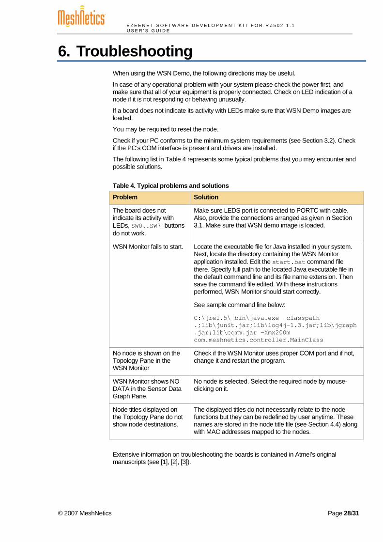
Table 4. Typical problems and solutions
Problem Solution
The board does not indicate its activity with LEDs, SW0..SW7 buttons do not work.
Make sure LEDS port is connected to PORTC with cable. Also, provide the connections arranged as given in Section 3.1. Make sure that WSN demo image is loaded.
WSN Monitor fails to start. Locate the executable file for Java installed in your system. Next, locate the directory containing the WSN Monitor application installed. Edit the start.bat command file there. Specify full path to the located Java executable file in the default command line and its file name extension. Then save the command file edited. With these instructions performed, WSN Monitor should start correctly.
See sample command line below:
C:\jre1.5\ bin\java.exe -classpath .;lib\junit.jar;lib\log4j-1.3.jar;lib\jgraph.jar;lib\comm.jar -Xmx200m com.meshnetics.controller.MainClass
No node is shown on the Topology Pane in the WSN Monitor
Check if the WSN Monitor uses proper COM port and if not, change it and restart the program.
WSN Monitor shows NO DATA in the Sensor Data Graph Pane.
No node is selected. Select the required node by mouse-clicking on it.
Node titles displayed on the Topology Pane do not show node destinations.
The displayed titles do not necessarily relate to the node functions but they can be redefined by user anytime. These names are stored in the node title file (see Section 4.4) along with MAC addresses mapped to the nodes.
Extensive information on troubleshooting the boards is contained in Atmel’s original manuscripts (see [1], [2], [3]).
© 2007 MeshNetics Page 28/31
E Z E E N E T S O F T W A R E D E V E L O P M E N T K I T F O R R Z 5 0 2 1 . 1 U S E R ’ S G U I D E
Appendices
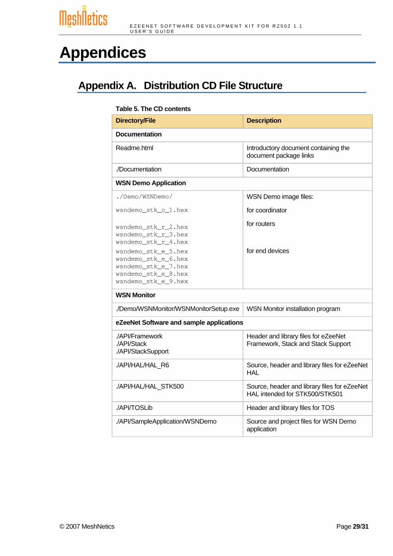
Appendix A. Distribution CD File Structure
Table 5. The CD contents
Directory/File Description
Documentation
Readme.html Introductory document containing the document package links
./Documentation Documentation
WSN Demo Application
./Demo/WSNDemo/
wsndemo_stk_c_1.hex wsndemo_stk_r_2.hex wsndemo_stk_r_3.hex wsndemo_stk_r_4.hex wsndemo_stk_e_5.hex wsndemo_stk_e_6.hex wsndemo_stk_e_7.hex wsndemo_stk_e_8.hex wsndemo_stk_e_9.hex
WSN Demo image files:
for coordinator
for routers
for end devices
WSN Monitor
./Demo/WSNMonitor/WSNMonitorSetup.exe WSN Monitor installation program
eZeeNet Software and sample applications
./API/Framework
./API/Stack
./API/StackSupport
Header and library files for eZeeNet Framework, Stack and Stack Support
./API/HAL/HAL_R6 Source, header and library files for eZeeNet HAL
./API/HAL/HAL_STK500 Source, header and library files for eZeeNet HAL intended for STK500/STK501
./API/TOSLib Header and library files for TOS
./API/SampleApplication/WSNDemo Source and project files for WSN Demo application
© 2007 MeshNetics Page 29/31

E Z E E N E T S O F T W A R E D E V E L O P M E N T K I T F O R R Z 5 0 2 1 . 1 U S E R ’ S G U I D E
© 2007 MeshNetics Page 30/31

E Z E E N E T S O F T W A R E D E V E L O P M E N T K I T F O R R Z 5 0 2 1 . 1 U S E R ’ S G U I D E
© 2007 MeshNetics Page 31/31