A Proposal to Extend the OpenMP Tasking Model with Dependent Tasks
Upload
khangminh22Category
view
1download
0
Operating Instructions for Band Saw
Extend 900.720
Before transporting and using the machine, please read the instructions thoroughly!
Serial number:

Version 1.05 / June 2008
BOMAR, spol. s r.o. Extend 900.720 Těžební 1236/1 62700 Brno CZECH REPUBLIC
Service and Information In case of technical difficulties or spare parts order, please contact your dealer:
Or contact Bomar, spol. s r.o. directly: BOMAR, spol. s r.o. Těžební 1236/1 62700 Brno CZECH REPUBLIC Telephone: +420 – 533 426 100 Fax: +420 – 533 426 109 e-mail: [email protected] WWW: http://www.bomar.cz We are available Mondays to Fridays from 700 to 1600. Version 1.05 / June 2008
BOMAR, spol. s r.o. © - Subject to modifications and amendments

Version 1.05 / June 2008
BOMAR, spol. s r.o. Extend 900.720 Těžební1236/1 62700 Brno CZECH REPUBLIC
3
Content
1. INTRODUCTION.................................................................................................................. 6
2. BAND SAW USING ............................................................................................................. 6
3. TECHNICAL DATA .............................................................................................................. 7
4. SAFETY NOTES.................................................................................................................. 8
4.1. GENERAL ..................................................................................................................... 8
4.2. PROTECTIVE SUIT AND PERSONAL SAFETY ........................................................................ 8
4.3. SAFETY NOTES FOR MACHINE OPERATOR .......................................................................... 9
4.4. SAFETY NOTES FOR THE SERVICING AND REPAIRS ............................................................ 10
4.5. SAFETY MACHINE ACCESSORIES .................................................................................... 11
5. SEZNAM BEZPEČNOSTNÍCH ZNAČEK / LISTE DER SICHERHEITSZEICHEN / LIST OF SAFETY SYMBOLS ........................................................................................................... 13
6. TRANSPORTATION AND STOCKING ............................................................................... 15
6.1. CONDITIONS FOR TRANSPORTATION AND STOCKING ......................................................... 15
6.2. SAFETY NOTES ........................................................................................................... 15
6.3. TRANSPORT AND STOCKING PREPARATIONS .................................................................... 16
6.4. TRANSPORT AND STOCKING .......................................................................................... 16
7. ACTIVATION ..................................................................................................................... 17
7.1. MACHINE WORKING CONDITIONS .................................................................................... 17
7.2. MACHINE INSTALLING AND LEVELLING ............................................................................. 17
7.3. ELECTRICAL CONNECTION ............................................................................................ 18
7.4. FILLING OF THE COOLING SYSTEM .................................................................................. 19
7.5. CHECK MACHINE FUNCTIONS ......................................................................................... 20
8. CONTROL PANEL – DESCRIPTION .................................................................................. 21
9. STARTING THE BAND SAW ............................................................................................. 24
10. PREPARATIVE MODE ...................................................................................................... 25
10.1. ENTRANCE TO MENU .................................................................................................... 25
10.2. CUTTING PARAMETERS ................................................................................................. 25
10.3. INTERRUPTING THE CYCLE SELECTION ............................................................................ 25
10.4. VICE PARAMETERS (VICE OPENING) ............................................................................... 25
10.5. STOP TIME OF THE HYDRAULICS .................................................................................... 25
10.6. SWARF CONVEYOR ...................................................................................................... 25
10.7. LANGUAGE VERSION SELECTION .................................................................................... 25
11. SEMI-AUTOMATIC CYCLE................................................................................................ 26
11.1. CYCLE BREAKING ........................................................................................................ 27 11.1.1. STOP button ................................................................................................................... 27 11.1.2. TOTAL STOP button ....................................................................................................... 27
12. MATERIAL INSERTION ..................................................................................................... 28
12.1. SAFETY NOTES ........................................................................................................... 28
12.2. HANDLING AGENT SELECTION ........................................................................................ 28
12.3. MATERIAL INSERTION ................................................................................................... 28
12.4. BUNDLE MATERIAL CUTTING .......................................................................................... 29
13. BAND SAW ADJUSTING ................................................................................................... 30
Version 1.05 / June 2008
BOMAR, spol. s r.o. Extend 900.720 Těžební 1236/1 62700 Brno CZECH REPUBLIC
4
13.1. SAFETY NOTES ........................................................................................................... 30
13.2. SAW FRAME LIFT STOP SETTING .................................................................................... 30
13.3. ADJUSTING BAND GUIDES ............................................................................................. 31
13.4. CUTTING SPEED ADJUSTING .......................................................................................... 31
13.5. ADJUSTMENT OF PRESSURE IN THE CUT.......................................................................... 31
14. BLANKS REMOVING FROM THE BAND SAW ................................................................... 32
14.1. SAFETY NOTES ........................................................................................................... 32
14.2. HANDLING AGENT SELECTION ........................................................................................ 32
14.3. BLANKS REMOVING ...................................................................................................... 32
15. SELECTION AND REPLACEMENT OF THE SAW BAND ................................................... 33
15.1. SAFETY NOTES ........................................................................................................... 33
15.2. SAW BAND SIZE ........................................................................................................... 33
15.3. SELECTION OF THE SAW BAND TOOTH SYSTEM :................................................................ 33
15.4. SAW BAND RUNNING - IN ............................................................................................... 35
15.5. SAW BAND DISMANTLING .............................................................................................. 36
15.6. SAW BAND INSTALLATION ............................................................................................. 36
15.7. SAW BAND STRETCHING AND INSPECTION ....................................................................... 38 15.7.1. Saw band stretching ........................................................................................................ 38 15.7.2. Saw band inspection ....................................................................................................... 38
16. COOLING AGENTS AND CHIPS DISPOSAL ..................................................................... 39
16.1. SAFETY NOTES ........................................................................................................... 39
16.2. COOLING LIQUID PREPARATION ..................................................................................... 39
16.3. COOLANT DEVICE INSPECTION ....................................................................................... 40
16.4. CHIPS DISPOSAL ......................................................................................................... 41
17. GREASES AND OILS ........................................................................................................ 42
17.1. GEARBOX OILS ............................................................................................................ 42
17.2. HYDRAULIC OILS ......................................................................................................... 43
17.3. LUBRICANT GREASES ................................................................................................... 43
18. SERVICE .......................................................................................................................... 44
18.1. MACHINE CLEANING ..................................................................................................... 44
18.2. LUBRICATION .............................................................................................................. 44
18.3. COOLING LIQUID INSPECTION ........................................................................................ 44
18.4. HYDRAULIC OIL LEVEL CHECK ........................................................................................ 44
19. ADJUSTMENT .................................................................................................................. 46
19.1. HARD METAL GUIDES ADJUSTMENT ................................................................................ 46
19.2. SAW BAND RUN ADJUSTMENT ON THE STRETCHING WHEEL ................................................ 46
19.3. BRUSH ADJUSTMENT .................................................................................................... 46
19.4. ADJUSTING OF THE LIMIT SWITCH OF THE SAW BAND STRETCHING ...................................... 47
19.5. SAW ARM LOWER POSITION STOP ADJUSTMENT ................................................................ 47
19.6. LIMIT SWITCH ADJUSTMENT OF THE SAW FRAME LOWER POSITION ...................................... 47
19.7. ADJUSTMENT OF THE CUTTING PRESSURE REGULATION .................................................... 49
20. WORN PIECES REPLACEMENT ....................................................................................... 51
20.1. PUSHING BEARING REPLACEMENT .................................................................................. 51
20.2. SAW BAND GUIDING PULLEYS REPLACEMENT ................................................................... 52
20.3. HARD METAL GUIDES REPLACEMENT .............................................................................. 54
20.4. ROUND BRUSH REPLACEMENT ....................................................................................... 56

Version 1.05 / June 2008
BOMAR, spol. s r.o. Extend 900.720 Těžební1236/1 62700 Brno CZECH REPUBLIC
5
21. ROZMĚROVÉ SCHÉMA / AUFSTELLZEICHNUNG / INSTALLATION DIAGRAM ................ 57
22. ELEKTRICKÁ SCHÉMATA / ELEKTROSCHEMAS / WIRING DIAGRAMS .......................... 59
23. KUSOVNÍK ELEKTROSOUČÁSTÍ / STÜCKLISTE DER ELEKTROTEILEN / PIECE LIST OF ELEKTROPARTS .............................................................................................................. 71
24. HYDRAULICKÉ SCHÉMA / HYDRAULIKSCHEMA / HYDRAULIC DIAGRAM ..................... 73
25. VÝKRESY SESTAV PRO OBJEDNÁNÍ NÁHRADNÍCH DÍLŮ / ZEICHNUNGEN FÜR BESTELLUNG DER ERSATZTEILE / DRAWING ASSEMBLIES FOR SPARE PARTS ORDER ......................................................................................................................................... 77
25.1. PÁSOVÁ PILA / BANDSÄGE / BAND SAW ........................................................................... 78
25.2. PODSTAVEC / UNTERGESTELL / PEDESTAL ...................................................................... 80
25.3. RAMENO / ARM / ARM .................................................................................................. 82
25.4. SVĚRÁK / SCHRAUBSTOCK / VICE .................................................................................. 84
25.5. POHON / ANTRIEB / DRIVE ............................................................................................ 86
25.6. VÁLEC ZVEDACÍ / HEBEZYLINDER / LIFTING CYLINDER ....................................................... 88
25.7. NAPÍNÁNÍ PILOVÉHO PÁSU / SÄGEBANDSPANNUNG / SAW BAND STRETCHING ....................... 90
25.8. VEDENÍ PÁSU / SÄGEBANDFÜHRUNG / SAW BAND GUIDING ................................................ 92
25.9. KARTÁČEK / BÜRSTE / BRUSH ....................................................................................... 96
25.10. LEVÁ VODÍCÍ KOSTKA / LINKER FÜHRUNGSKLOTZ / LEFT GUIDING CUBE ............................... 97
25.11. PRAVÁ VODÍCÍ KOSTKA / RECHTER FÜHRUNGSKLOTZ / RIGHT GUIDING CUBE ....................... 99
25.12. TŘÍSKOVÝ VYNAŠEČ / SPÄNEFÖRDERER / SWARF CONVEYOR .......................................... 102
25.13. POHON TŘÍSKOVÉHO VYNAŠEČE / ANTRIEB VON SPÄNEFÖRDERER / DRIVE ........................ 104
25.14. REGULACE TLAKU SVĚRÁKU /SPANDRUCKREGULIERUNG/VICE PRESSURE REGULATION ....... 106
25.15. KOSTKA / KLOTZ / CUBE ............................................................................................. 108
26. UMÍSTĚNÍ BEZPEČNOSTNÍCH ZNAČEK / VERTEILUNG DER SICHERHEITSZEICHEN / POSITION OF SAFETY SYMBOLS .................................................................................. 110
26.1. PILA / BANDSÄGE / BAND SAW ..................................................................................... 110
26.2. NAPÍNACÍ A HNACÍ KOLO / UMLENKRAD UND ANTRIEBSRAD / TIGHTENING WHEEL AND DRIVING
WHEEL ..................................................................................................................... 111
27. TROUBLESHOOTING TABLE ......................................................................................... 113
27.1. MECHANICAL PROBLEMS............................................................................................. 113
27.2. ELECTRIC AND HYDRAULIC PROBLEMS .......................................................................... 115
28. SPECIAL ACCESSORY ................................................................................................... 117
28.1. VICE PRESSURE REGULATION ...................................................................................... 117
28.2. MICRONISER ............................................................................................................. 117
28.3. TENZOMAT ............................................................................................................... 117
DECLARATION OF CONFORMITY ......................................................................................... 119

Version 1.05 / June 2008
BOMAR, spol. s r.o. Extend 900.720 Těžební 1236/1 62700 Brno CZECH REPUBLIC
10
Do not touch the cooling liquid with bare hands! Do not set the nozzle of the cooling liquid, when the machine is started on! Do not remove the chips from the working area of the machine, when the machine is started on! Do not use the compressed air for the machine cleaning or for the chips removing! Use the protective instruments for chips removal!
4.4. Safety notes for the servicing and repairs
The machine is equipped with safety accessories. It protects the operator from injuries and the machine before damage. The safety accessories are blocking accessories, emergency switches and covers. Check once in a week the function of the safety accessories. If the safety accessories are functionless, you must stop work and repair or change the safety accessories.
TOTAL STOP button
TOTAL STOP button is used for emergency switching – off the machine in case defect or health hazard. By pressing TOTAL STOP button is interrupted the supply of the electrical power. If any damages or fault appears, immediately press TOTAL STOP button! Release the pressing button is possible by twisting of the upper part of the button.
Enhanced risk! Do not come into or intervene in the cutting area. Otherwise, there is possibility of heavy injury.
Saw band stretching and rupturing inspection
This device checks the saw band stretching and causes immediate machine shut – down in the event the band ruptures. The device contains limit switch. Check the stretching carefully and periodically – eventually adjust.
Left saw band cover

Version 1.05 / June 2008
BOMAR, spol. s r.o. Extend 900.720 Těžební1236/1 62700 Brno CZECH REPUBLIC
11
It covers the visible area of the saw band from left guiding cube to the frame. Never switch on the saw band driver if this cover is not mounted!
Left cover
It covers tightening wheel. If the cover is opened during operation, the limit switch is opened and the band saw is stopped. The band saw is not possible start in set mode. The band saw is stated to the operation, when the cover is closed!
Right cover
It covers driving wheel. If the cover is opened during operation, the limit switch is opened and the band saw is stopped. The band saw is not possible start in set mode. The band saw is stated to the operation, when the cover is closed!
4.5. Safety machine accessories
The machine is equipped with safety accessories. It protects the operator from injuries and the machine before damage. The safety accessories are blocking accessories, emergency switches and covers. Check once in a week the function of the safety accessories. If the safety accessories are functionless, you must stop work and repair or change the safety accessories.
Enhanced risk! Do not come into or intervene in the cutting area. Otherwise, there is possibility of heavy injury.

Version 1.05 / June 2008
BOMAR, spol. s r.o. Extend 900.720 Těžební 1236/1 62700 Brno CZECH REPUBLIC
12
TOTAL STOP button
TOTAL STOP button is used for emergency switching – off the machine in case defect or health hazard. By pressing TOTAL STOP button is interrupted the supply of the electrical power. If any damages or fault appears, immediately press TOTAL STOP button! Release the pressing button is possible by twisting of the upper part of the button.
Saw band stretching and rupturing inspection
This device checks the saw band stretching and causes immediate machine shut – down in the event the band ruptures. The device contains limit switch. Its setting is described in chapter “Service and Adjusting” . Check the stretching carefully and periodically – eventually adjust. To stretch the saw band press the left button (left arrow). To release the saw band press the right button (right arrow). Stretching value is set by the producer.
Left cover
It covers tightening wheel. If the cover is opened during operation, the limit switch is opened and the band saw is stopped. The band saw is not possible start in set mode. The band saw is stated to the operation, when the cov er is closed!
Right cover
It covers driving wheel. If the cover is opened during operation, the limit switch is opened and the band saw is stopped. The band saw is not possible start in set mode. The band saw is stated to the operation, when the cover is closed!

Version 1.05 / June 2008
BOMAR, spol. s r.o. Extend 900.720 Těžební1236/1 62700 Brno CZECH REPUBLIC
13
5. Seznam bezpečnostních značek / Liste der Sicherheitszeichen / List of safety symbols
Značka / Zeichen / Symbol Význam / Bedeutung / Signification Objednací číslo / Bestell - Nr. / Reference No.
NS-Nebezpečí stlačení / Pressunggefahr / Crushing hazard
NR-Nebezpečí říznutí / Schnittgefahr / Cutting or severing hazard
NN-Nebezpečí nárazu / Stoßgefahr / Impact hazard
NV-Nebezpečí vtažení / Einzuggefahr / Drawing – in hazard
NZ- Nebezpečí zachycení / Erfassunggefahr / Tramping hazard
NT-Nebezpečí střihu / Schnittgefahr / Shearing hazard
NE-Nebezpečí úrazu elektrickým proudem / Verletzunggefahr vom elektrischen Strom / Electrical hazard

Version 1.05 / June 2008
BOMAR, spol. s r.o. Extend 900.720 Těžební 1236/1 62700 Brno CZECH REPUBLIC
14
HV-Hlavní vypínač / Hauptschalter / Main switch
SOL-Směr otáčení doleva / Drehrichtung nach links / direction of rotation left
SOP-Směr otáčení doprava / Drehrichtung nach fechte / direction of rotation right
SOO-Směr otáčení oboustranně / Drehrichtung doppelseitig / direction of rotation double-sided
OBS-Noste ochranné brýle a sluchátka / Tragen Sie eine Schutzbrille und Gehörschutz / Wear protective googles and headphones
PO-Noste pevnou pracovní obuv / Tragen Sie Sicherheitsschuhe / Wear fixed protective shoes
CZ-Přečíst návod k použití / Bedienungsanleitung lesen / Read the operating instructions

Version 1.05 / June 2008
BOMAR, spol. s r.o. Extend 900.720 Těžební1236/1 62700 Brno CZECH REPUBLIC
15
6. Transportation and stocking
6.1. Conditions for transportation and stocking
Keep recommendations for the manufacturers for transportation and stocking! If the recommendations are not kept, damage can occur to the machine.
Conditions for transportation and stocking:
• Temperature of the air from –25°C to +55°C, for a short term (max. 24 hours) temperature of the air until +70°C.
• Do not expose the machine to radiation (for example microwave radiation, ultra-violet radiation, laser radiation, X – ray radiation). Radiation can cause problems with the machine function and deteriorating condition of the isolation.
• Take measures, to prevent damage by dampness, by vibrations and by shakes.
6.2. Safety notes
Keep safety notes for the transport!
Always wear protective hardhat to avoid hard injuries during loading and transportation!
Wear protective gloves! Sharp edges of the machine, pallets and means of transport can injure your hands.
Wear safety boots! Loose parts and packing materials can cause serious injuries.
Do not use a forklift truck for handling the machine, if you do not have licence for it! Do not move under suspended loads! Fault in lifting device may cause serious injury. Keep a safe distance from the machine during the transport.

Version 1.05 / June 2008
BOMAR, spol. s r.o. Extend 900.720 Těžební 1236/1 62700 Brno CZECH REPUBLIC
16
6.3. Transport and stocking preparations
Close the vice and thoroughly oil all blank surfaces. Lower the saw frame to the lowest position. Make sure to empty the machine of all traces of the cooling agent. Fasten all loose parts securely to the machine. Pack and wrap the control desk securely to avoid damage during transport. Fix the stickers stating the minimum approximate machine weight to at least five well visible places. The machine has to be screwed to a pallet for the transport!
6.4. Transport and stocking
Handle the machine only with suspension cables and the
crane. The pedestal is equipped with slots =70 mm. Insert the appropriate steel bars to all of these slots (see arrows on the picture). It is possible use two long or four short bars. Fix the suspension cables to the steel bars. Make sure that the suspension cables and the crane had sufficient capacity. Make sure that the van or the trailer had sufficient capacity. The machine must be secured during transportation. Screw on the palette to the floor of the van or the trailer. Be careful that the machine is not damaged during transportation.
It is forbidden to handle the machine any other way (for example by, lifting by the saw frame of the band saw), than it is written in this operating instructions, the machine can be damaged!

Version 1.05 / June 2008
BOMAR, spol. s r.o. Extend 900.720 Těžební1236/1 62700 Brno CZECH REPUBLIC
17
7. Activation
7.1. Machine working conditions
Keep the conditions of the manufacturer for machine operating! If recommendations are not kept, damage can occur to the machine.
The manufacturer warrants the correct function of the machine for these conditions: At temperature air from +5°C to +40°C, the temperature average during 24 hours must not exceed over +35°C. At relative dampness of the air in the extend from 30% to 95% (not concentrate). Altitude higher than 1000 metres. Do not expose the machine to the radiation (for example microwave radiation, ultra-violet radiation, laser radiation, X – ray radiation). Radiation can cause problems with the machine function and deteriorating condition of the isolation.
7.2. Machine installing and levelling
Check the floor supporting capacity before machine installing. If the floor capacity does not agree with requirements, you must prepare the necessary base for the machine.
Minimal requirement: machine weight (chapter Technical data) + weight of accessories + maximum weight of material
The machine must be levelled at the horizontal position. All feet of the machine must touch with the floor after levelling.
The machine must be levelled by means of the calibrated spirit level. Spirit level is put on the vice area. Set the roller conveyors according to the spirit level.
For machine levelling, take care that there is sufficient available space for operation, repair work, servicing of the machine and handling the material.
The machine including appended parts and accessories must be visible from the place of operation.

Version 1.05 / June 2008
BOMAR, spol. s r.o. Extend 900.720 Těžební 1236/1 62700 Brno CZECH REPUBLIC
18
7.3. Electrical connection
ATTENTION! Only a qualified professional must carry out the servicing and repairs of the electric equipment! Take special care during work with electrical equipment. High voltage shock can have fatal consequences! Always keep notes about work safety!
Electrical parameters of the machine: Service voltage: ~ 3 x 400 V, 50 Hz, TN-C-S Total input: see Technical data Max. fuse: 16 A
Before connecting switch off the main switch of the power supply circuit for the machine and ensure dry place when doing connecting works!
Service voltage must agree with the line voltage! Crosscut of the supply line must respond with rated current for max. machine load. Note: The values of the crosscut of the conductor and the rated current are in the norms. Connect the service cable of the machine on the clamps of the electric distribution. Note: The socket with the fork can be used only at the machines with the rated current less than 16A and total input less than 3 kW.
In case the machine is connected with a direct connection, an extra main switch must be added which can be locked in zero position. Attention! In this case the extra main switch becomes primary and the main switch on the machine has only secondary function.
Check the direction of the saw band! After the machine has been successfully connected, briefly switch on the machine and put the driving engine of the band in the running position. The direction must be in accordance with the arrow direction on the saw band cover. In case the direction of the saw band does not match, two phases at the terminal strip must be switched.

Version 1.05 / June 2008
BOMAR, spol. s r.o. Extend 900.720 Těžební1236/1 62700 Brno CZECH REPUBLIC
19
7.4. Filling of the cooling system
If handling cooling liquid, keep the notes about work safety and instructions of the cooling liquid manufacturer!
Wear protective gloves when working with cooling liquids!
Wear protective goggles! The cooling liquid can get into your eyes and cause serious injury.
Prepare the mixture of the water and the coo ling liquid. Keep the concentration specified by manufacturer.
Fill the mixture of the water and the cooling liquid to the tank of the cooling system. Area of the tank for the cooling liquid is discovered from the chapter „Technical data“.
Filling the tank with the cooling liquid, take care that the liquid does not drip out of the tank and the tank does not overflowed.
Keep by manufacturer specified recommendation for adding the anticorrosive agents, the antifreezes or other agents! For mixture of two different mixes can produce toxic and aggressive mixes, which can threaten your health or damage cooling system of the machine!
Note: If the machine is equipped with Microniser (see. Special accessory), fill the tank of the Microniser by specified cooling liquid. Microniser is ready for operation.

Version 1.05 / June 2008
BOMAR, spol. s r.o. Extend 900.720 Těžební 1236/1 62700 Brno CZECH REPUBLIC
20
7.5. Check machine functions
Before starting the check machine functions, you must read the chapter „Machine operation“. Do not carry out check machine functions, if you do not comprehend meaning of all buttons and all machine functions.
Check, if the machine or some parts of the machine were not damaged during transport.
Check, if covers are installed and functional.
Check by means of the Tenzomat (see Special accessory), if the saw band is correctly stretched. If it is necessary, you can stretch the saw band according to chapter „Selection and replacement of the saw band“. Values of the saw band stretching are on the Tenzomat.
Switch on the main switch and check the motors and systems (saw band drive, hydraulic pump, cooling pump, chips conveyor).
Open and close the main vice and the feeding vice. Drive the front feeder from the front position to the rear position. Turn the saw frame of the band saw from one outer pos ition to other outer position. Raise the saw frame to the top position and drop the saw frame to the lowest position.
Start the machine with the cooling pump and let it run without load until the cooling system will be filled with cooling liquid. As soon as the cooling liquid starts to escape from the nozzles of the cooling system, the cooling system is ready for the operation.
Carry one cycle of cutting without material. Check, if the machine runs with no irregularities. If all machine functions are right, the machine is ready for operation.

Version 1.05 / June 2008
BOMAR, spol. s r.o. Extend 900.720 Těžební1236/1 62700 Brno CZECH REPUBLIC
21
8. Control panel – description

Version 1.05 / June 2008
BOMAR, spol. s r.o. Extend 900.720 Těžební 1236/1 62700 Brno CZECH REPUBLIC
22
1 Display There are described all processes on display.
2 Safety circuit switching on Switch on the safety circuit by pressing button.
3
Cooling system selection You can select from three possibilities:
Cooling with Microniser
0 Without cooling
Cooling with water
4 START - Switch on the semi-automatic cycle By pressing 6 and button 4 is starting only the band saw drive. It is stopped with button 5.
5
STOP - Switch off the engine of the band saw It stops the engine of the machine. With holding button STOP during the time 2 second is stopped hydraulic engine ( if it running). The hydraulic engine is started automatic on switch whatever motion.(Open vice, close, Lift the saw arm, lower) or the cycle is starting with button Start.
6 Close the vice When this button is pressed, the vice is opened. This button may be used in semi-automatic cycle.
7 Open vice Vice is opened after pressing this button.
8 Lift the saw arm
9
Lower the saw arm If this button is pressed with 8 button together, the saw arm is starting chute on the cutting material with accelerated shift. ATTENTION! If you will be running with accelerated shift until the cut, the saw band may be damaged.
10 TOTAL – STOP button In emergency causes the machine must be immediately switched off.
11 LED- control lamp blink by cycle.
12 Frequency convertor Turn to change the speed of the saw band.
13 Cutting pressure manometer

Version 1.05 / June 2008
BOMAR, spol. s r.o. Extend 900.720 Těžební1236/1 62700 Brno CZECH REPUBLIC
23
14 Cutting pressure regulation Adjust the arm pressure to the cut.
15
Governing valve Adjust the speed of the arm sinking to the cut by governing valve. Notice: If you keep closing the throttle valve too tightly, the valve seat may wear off which causes its leakage. Therefore, close the valve always gently.
16
Deblock Use the deblock to replace the saw band. Position 0 – operating mode. During the running of the machine, the switch must be in position 0. Position 1 – saw band replacement. In this position it is possible to run the hydraulics and strain and release the saw band despite of the open covers. The functions activate only by buttons on the arm. Other functions are blocked.

Version 1.05 / June 2008
BOMAR, spol. s r.o. Extend 900.720 Těžební 1236/1 62700 Brno CZECH REPUBLIC
24
9. Starting the band saw
1) Switch on the main switch of the band saw. The main switch is situated on the side of the switchboard.
2) Switch on the safety circuit of the band saw (button 2 – control panel of the band saw).

Version 1.05 / June 2008
BOMAR, spol. s r.o. Extend 900.720 Těžební1236/1 62700 Brno CZECH REPUBLIC
25
10. Preparative mode
10.1. Entrance to menu Press button 5+6+7+8+9 together. Hydraulic must be off.
10.2. Cutting parameters
You can select, if you want to stop the saw band drive in upper or lower position of the saw arm, or do not stop the drive.
If you strain button 6, the saw band drive will be stopped in the bottom position of the saw arm or in the top position.
10.3. Interrupting the cycle selection
Press button 6 to preselect the cycle interrupt. Press button 9 to move to the next menu
10.4. Vice parameters (vice opening) 1) Press button 9 to entrance to menu: Vice parameters.
2) By repeated pressing button 6 you select: up – not - down release.
Press button 9 to move to the next menu
10.5. Stop time of the hydraulics 1) Press button 9 to move to this menu.
2) To set the stop time, press button 6: up- down – no loosen
Press button 9 to move to the next menu
10.6. Swarf conveyor
Swarf conveyor will be automatic stoped and starting with saw band drive.
10.7. Language version selection
By repeated pressing button 6, select the language. Press button 9 to ending Preparative mode.

Version 1.05 / June 2008
BOMAR, spol. s r.o. Extend 900.720 Těžební 1236/1 62700 Brno CZECH REPUBLIC
26
11. Semi-automatic cycle 1) Lift the saw arm to the top position by pressing button „8“. 2) Open the vice by pressing button „7“. 3) Clamp material to the vice by pressing button „6“.
4) Lower the frame about 10 mm above the material by button „9“. ATTENTION! Do not move the saw frame to the material, when the saw band driving is not running! Do not move the saw frame to the material with accelerated motion! The saw band can be damaged!
5) Select the max. heigth of the arm with limit switch.
6) Set the saw band speed according to the kind of the cutting material.
7) Set the speed of the arm sinking by adjust governing valve „15“.
8) You can clear the register of the performed cycles by button 5 – 6 second stop on .
9) Press button „4“ (START of semi-automatic cycle). Note: Press button „5“ (STOP of semi-automatic cycle). In risk of injury or damage of the band saw, press the emergency button TOTAL STOP “10”.
10) The band saw clamps the material to the vice and it makes the cut.
11) Open the vice. If the vice is not opened, you can open it by button „7“. Remove the blank.
12) You can repeat whole process.

Version 1.05 / June 2008
BOMAR, spol. s r.o. Extend 900.720 Těžební1236/1 62700 Brno CZECH REPUBLIC
27
11.1. Cycle breaking 11.1.1. STOP button
Semi-automatic cycle is interrupted by pressing button „5“ (STOP of the semi-automatic cycle).
The arm is lifted to the top position and the saw band drive is stopped.
By pressing button „4“ (START of the semi-automatic cycle), you can start the cycle.
11.1.2. TOTAL STOP button In case of the risk, press button TOTAL STOP „10“.
After pressing TOTAL STOP button, saw band drive is immediately broken and the arm sinking is stopped.
Reactivation:
1) Turn button TOTAL STOP according to the arrows (on the button).
2) Switch on the safety circuit by button „2“.
3) By pressing button „4“ (START of the semi-automatic cycle), you can start the cycle. The arm is lifted to the top position and the saw band starts the cycle.

Version 1.05 / June 2008
BOMAR, spol. s r.o. Extend 900.720 Těžební 1236/1 62700 Brno CZECH REPUBLIC
28
12. Material insertion
12.1. Safety notes
Keep safety notes!
Wear protective gloves! Material may have sharp edges and may cause cuts.
Wear protective boots! Falling cut pieces can cause serious injuries.
Wear protective hardhat! Falling work pieces can cause severe head injuries.
Never walk under a suspended load! Never climb onto the gravity-roller conveyor!
Do not hold the material for clamping material to the vice! The vice can cause injury!
12.2. Handling agent selection
Use the strong handling agents to lift and transfer the material!
Handle with the material only with the lift truck or use the suspension strands and the crane! Do not use the lift truck or crane in case that you do not have the licence to handle with it!
12.3. Material insertion
Insert material to the vice and ensure that the material cannot move in the vice or fall from the vice after the clamping.
If you cut long pieces of the material (for example rod, tube), you must use the roller conveyors for material shifting to the band saw. The roller conveyors are described in the chapter „Roller conveyors and accessories“.

Version 1.05 / June 2008
BOMAR, spol. s r.o. Extend 900.720 Těžební1236/1 62700 Brno CZECH REPUBLIC
29
Make sure the conveyor is long enough and the material cannot tip off the conveyor.
Be especially careful with round materials that it always stays on two vertical rollers and that it cannot fall off the conveyor!
12.4. Bundle material cutting
If you want to cut the material in the bundle, there are suggestions for the positioning of bundles
Round material bundle. Take care especially with round material that the bars are put according to the picture. If the bars are put differently, you may have problems with movement.
Always weld the material at the rear end of the bundle to secure it from moving. ATTENTION! Before welding always, switch the machine off at the main switch! The magnetic fields, which often occur during welding, may damage the controls!
Square material bundle.
Angled material bundle.
ATTENTION! Not all material shapes are suitable for bundle cuts. Keep the recommendation of your supplier of the saw bands for material insertion to the bundle.

Version 1.05 / June 2008
BOMAR, spol. s r.o. Extend 900.720 Těžební 1236/1 62700 Brno CZECH REPUBLIC
30
13. Band saw adjusting
13.1. Safety notes
Keep the safety notes! Work the machine with the highest safety!
Wear protective boots! Falling cut pieces can cause serious injuries.
Wear protective hardhat! Falling work pieces can cause severe head injuries.
13.2. Saw frame lift stop setting
If you want to shorten the time of operations in automatic cycle, you have to adjust the height of the saw arm according to the height of the cutting material.
1) Saw arm adjusting is sensed by the sensor. 2) By button 8 „The saw arm is up“, you have to go out
in the most high position. 3) Insert the material to the vice and you carefully sink
with the saw arm on the material using button 9 “Saw arm down”. Eventually by combination buttons 8 and 9 – fast feed.
4) You must adjust the saw arm 10mm above the
material.
5) Adjust arm stop length just above the sensor – shift stop length by turning arrestment wheel hard upon the sensor.

Version 1.05 / June 2008
BOMAR, spol. s r.o. Extend 900.720 Těžební1236/1 62700 Brno CZECH REPUBLIC
31
13.3. Adjusting band guides Band guides are adjusted automatically together with vice.
13.4. Cutting speed adjusting
Speed of the saw band is possible change from 20 to 120 m/min. You can effect to adjusting speed of the saw band following:
Use the frequency convertor 12 to adjust requested speed of the saw band. You can see the band speed on display 1 during semi automatic cycle.
13.5. Adjustment of pressure in the cut
The band saw Extend 900.720 is equipped with cutting pressure regulation on the both guiding cubes. Note! Guiding cubes are equipped with taps which must be open during operation!
Pressure adjusting is performed with regulating wheel (position 14 – control panel). The pressure to the cut is displayed on the cutting pressure manometer 13.
Lower pressure set up by turning counter-clockwise.
Higher pressure set up by turning clockwise.

Version 1.05 / June 2008
BOMAR, spol. s r.o. Extend 900.720 Těžební 1236/1 62700 Brno CZECH REPUBLIC
32
14. Blanks removing from the band saw
14.1. Safety notes
Keep the safety notes! Work the machine with the highest safety!
Wear protective gloves! Material may have sharp edges and may cause cuts.
Wear protective boots! Falling cut pieces can cause serious injuries.
Wear protective hardhat! Falling work pieces can cause severe head injuries.
Take care, that there is nobody in the working area of the band saw! The moving material can cause the serious injuries!
14.2. Handling agent selection
Use the strong handling agents to lift and transfer the material!
Handle with the material only with the lift truck or use the suspension strands and the crane! Do not use the lift truck or crane in case that you do not have the licence to the handle with it!
14.3. Blanks removing Remove the blanks from the band saw.

Version 1.05 / June 2008
BOMAR, spol. s r.o. Extend 900.720 Těžební1236/1 62700 Brno CZECH REPUBLIC
33
15. Selection and replacement of the saw band
15.1. Safety notes
Wear protective gloves! The saw band has sharp teeth and can cause serious injuries to your hands.
Wear protective goggles! The saw band can snap during assembly and seriously injure your eyes.
Refit the saw band cover only after you have installed and tightened the saw band.
15.2. Saw band size
8560 x 54 x 1,6 mm
15.3. Selection of the saw band tooth system:
The manufacturers provide the saw bands with constant and variable tooth system. The important factor for selection of the tooth system is length of the cutting canal with respect to the size of the product.
1) Constant tooth system – the saw band has parallel tooth pitch all over length. This way is suitable for cutting of solid material.
2) Variable tooth system – tooth pitch is variable. Variable tooth system is used for profiled materials and bundle cutting. Variable tooth pitch lowers vibration of the saw band, increases service life of the saw band and quality of the cutting area.
In tables, there are advised type of the tooth system depending on sizes and form of the cutting material.
Footnotes: ZpZ – teeth number on one inch. S – tooth with zero angle of the teeth. K – tooth with positive angle of the teeth.
Examples of the tooth system marking: 32 S – number „32“ means 32 teeth on one inch (that means constant tooth system), letter „S“ marks teeth with zero angle of the tooth. 4-6 K – number „4-6“ means 4 till 6 teeth on one inch (that means variable tooth system); letter „K“ marks teeth with positive angle of the teeth.

Version 1.05 / June 2008
BOMAR, spol. s r.o. Extend 900.720 Těžební 1236/1 62700 Brno CZECH REPUBLIC
34
Tables for teeth selection:
SHAPED MATERIAL (Dp, S = mm)
Dp
S
Dp
S
S
Dp
Dp
S
Dp
S
Note: Table shows tooth system selection for cutting one piece of the profile. For cutting of more pieces of the profiles (bundle), you must think of the size of the wall as double size of the wall of one profile (that means, size „S“ equates to 2 x S). In table, there are tooth systems constant and variable.
Size of the wall S [mm]
Tooth system (ZpZ) Outer diameter of the profile Dp [mm]
20 40 60 80 100 120
2 32 S 24 S 18 S 18 S 14 S 14 S
3 24 S 18 S 14 S 14 S 10 - 14 S 10 - 14 S
4 24 S 14 S 10 - 14 S 10 - 14 S 8 - 12 S 8 - 12 S
5 18 S 10 - 14 S 10 - 14 S 8 - 12 S 6 - 10 S 6 - 10 S
6 18 S 10 - 14 S 8 - 12 S 8 - 12 S 6 - 10 S 6 - 10 S
8 14 S 8 - 12 S 6 - 10 S 6 - 10 S 5 - 8 S 5 - 8 S
10 - 6 - 10 S 6 - 10 S 5 - 8 S 5 - 8 S 5 - 8 S
12 - 6 - 10 S 5 - 8 S 5 - 8 S 4 - 6 K 4 - 6 K
15 - 5 - 8 S 5 - 8 S 4 - 6 K 4 - 6 K 4 - 6 K
20 - - 4 - 6 K 4 - 6 K 4 - 6 K 3 - 4 K
30 - - - 3 - 4 K 3 - 4 K 3 - 4 K
50 - - - - - 3 - 4 K
Size of the wall S [mm]
Tooth system (ZpZ) Outer diameter of the profile Dp [mm]
150 200 300 500 750 1000
2 10 - 14 S 10 - 14 S 8 - 12 S 6 - 10 S 5 - 8 S 5 - 8 S
3 8 - 12 S 8 - 12 S 6 - 10 S 5 - 8 S 4 - 6 K 4 - 6 K
4 6 - 10 S 6 - 10 S 5 - 8 S 4 - 6 K 4 - 6 K 4 - 6 K
5 6 - 10 S 5 - 8 S 4 - 6 K 4 - 6 K 4 - 6 K 3 - 4 K
6 5 - 8 S 5 - 8 S 4 - 6 K 4 - 6 K 3 - 4 K 3 - 4 K
8 5 - 8 S 4 - 6 K 4 - 6 K 3 - 4 K 3 - 4 K 3 - 4 K
10 4 - 6 K 4 - 6 K 4 - 6 K 3 - 4 K 3 - 4 K 2 - 3 K
12 4 - 6 K 4 - 6 K 3 - 4 K 3 - 4 K 2 - 3 K 2 - 3 K
15 4 - 6 K 3 - 4 K 3 - 4 K 2 - 3 K 2 - 3 K 2 - 3 K
20 3 - 4 K 3 - 4 K 2 - 3 K 2 - 3 K 2 - 3 K 2 - 3 K
30 3 - 4 K 2 - 3 K 2 - 3 K 2 - 3 K 1,4 - 2 K 1,4 - 2 K
50 2 - 3 K 2 - 3 K 2 - 3 K 1,4 - 2 K 1,4 - 2 K 1,4 - 2 K
75 - 2 - 3 K 1,4 - 2 K 1,4 - 2 K 1,4 - 2 K 0,75 - 1,25 K
100 - - 1,4 - 2 K 0,75 - 1,25 K 0,75 - 1,25 K 0,75 - 1,25 K
150 - - - 0,75 - 1,25 K 0,75 - 1,25 K 0,75 - 1,25 K
200 - - - 0,75 - 1,25 K 0,75 - 1,25 K 0,75 - 1,25 K
Version 1.05 / June 2008
BOMAR, spol. s r.o. Extend 900.720 Těžební1236/1 62700 Brno CZECH REPUBLIC
35
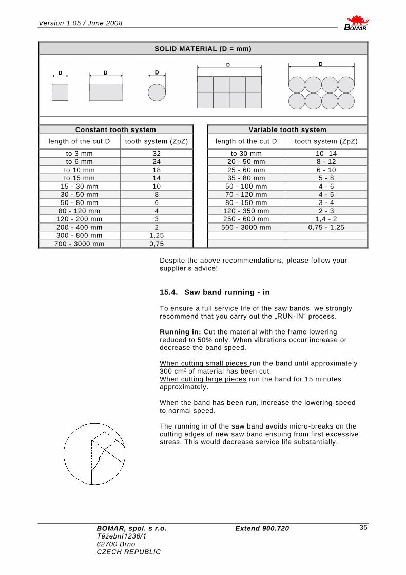
SOLID MATERIAL (D = mm)
D
D
D
D
D
Constant tooth system Variable tooth system
length of the cut D tooth system (ZpZ) length of the cut D tooth system (ZpZ)
to 3 mm 32 to 30 mm 10 -14
to 6 mm 24 20 - 50 mm 8 - 12
to 10 mm 18 25 - 60 mm 6 - 10
to 15 mm 14 35 - 80 mm 5 - 8
15 - 30 mm 10 50 - 100 mm 4 - 6
30 - 50 mm 8 70 - 120 mm 4 - 5
50 - 80 mm 6 80 - 150 mm 3 - 4
80 - 120 mm 4 120 - 350 mm 2 - 3
120 - 200 mm 3 250 - 600 mm 1,4 - 2
200 - 400 mm 2 500 - 3000 mm 0,75 - 1,25
300 - 800 mm 1,25
700 - 3000 mm 0,75
Despite the above recommendations, please follow your supplier’s advice!
15.4. Saw band running - in
To ensure a full service life of the saw bands, we strongly recommend that you carry out the „RUN-IN“ process.
Running in: Cut the material with the frame lowering reduced to 50% only. When vibrations occur increase or decrease the band speed.
When cutting small pieces run the band until approximately 300 cm2 of material has been cut. When cutting large pieces run the band for 15 minutes approximately.
When the band has been run, increase the lowering-speed to normal speed.
The running in of the saw band avoids micro-breaks on the cutting edges of new saw band ensuing from first excessive stress. This would decrease service life substantially.

Version 1.05 / June 2008
BOMAR, spol. s r.o. Extend 900.720 Těžební 1236/1 62700 Brno CZECH REPUBLIC
36
The optimal running in of the saw band produces ideal rounded cutting edges and therefore the conditions for an optimal service life.
Note: Run regrinding saw bands too!
15.5. Saw band dismantling
1) Press the button 8 to lift the saw arm to maximum position. 2) Switch off hydraulic by button Stop 5.
3) Switch Deblock 16 to position 1.
4) Open covers of both drive wheels.
5) Dismantle yellow band cover. 6) Release screw tightening brush position.
7) Release the saw band by pressing left button.
8) Draw the saw band down from driving wheels. 9) After carefully take the saw band out of guiding cubes.
15.6. Saw band installation 1) Prior to installation, clean all track wheels, guide cubes
and inner side of the arm thoroughly of all traces of chips and dirt. Keep in mind the teeth direction when installing the saw band.
2) Insert new saw band in the guide cubes. Make sure the saw band runs between both guide rollers and it is pushed all the way to the top.

Version 1.05 / June 2008
BOMAR, spol. s r.o. Extend 900.720 Těžební1236/1 62700 Brno CZECH REPUBLIC
37
3) Put the saw band on both guide wheels. Make sure that the saw band ridge fits tightly to the wheel rim. Then push the saw band as far back as possible.
4) Press the right button to stretch the saw band. 5) Close the covers. 6) Turn the deblock 16 to position 0.
7) Saw band installation is finished.

Version 1.05 / June 2008
BOMAR, spol. s r.o. Extend 900.720 Těžební 1236/1 62700 Brno CZECH REPUBLIC
38
15.7. Saw band stretching and inspection
Right saw band stretching is one of the most important criteria’s, which influents accuracy and saw band service life. Stretch the saw bands according to the selected saw band and the band saw. Keep the recommendation of your manufacturer.
15.7.1. Saw band stretching 1) The saw band must not fall from the wheels after setting.
2) Install the Tenzomat on the saw band and secure it with screws.
3) Stretch the saw band until i t is stretched to the recommended value.
15.7.2. Saw band inspection Check the saw band in the guiding cubes and on the wheels. 1) Check, if the saw band is right in the guiding cubes.
2) Switch on the saw band drive and then after 10 seconds switch off saw band drive. If the saw band drive is not possible to switch on, set the limit switch of the saw band stretching according to the chapter „Servicing and adjustment“.
3) Switch off the main switch.
4) Open cover(s) of the wheels and check position of the saw band on the both wheels. - if the distance between backside of the saw band and the offset wheel is 1 mm, setting is right. - if the distance is bigger than 1 mm, or the saw band is on the offset of the wheel, set the saw band according to chapter „Servicing and adjustment“.
5) Close cover of the saw band.

Version 1.05 / June 2008
BOMAR, spol. s r.o. Extend 900.720 Těžební1236/1 62700 Brno CZECH REPUBLIC
39
16. Cooling agents and chips disposal
16.1. Safety notes
Keep notes about work safety for handling cooling liquid!
When handling cooling agents always wear hazardous fluid-proof gloves!
Wear protective goggles! Cooling liquid can get in contact with your eyes and may cause permanent severe injuries.
Instructions for first help Pull off and safely remove polluted, soaked clothing.
For breathing, go out in the fresh air or look for first aid treatment.
Wash with water or use crèmes for contact with the skin. Flush with water for eyes and look for first aid treatment.
For swallowing, drink a lot of water and induce vomiting. Look for medical help.
16.2. Cooling liquid preparation
Prepare the mix of the water and cooling liquid. Conform the notes of the manufacturer and keep manufacturer -approved concentration.
All instructions are stated on the tank of the cooling liquid or in documents of the cooling liquid. For cooling liquid using and liquidation reads date of cooling liquid manufacturer, which it is necessary to keep.
Fill the mix of water and cooling liquid to the tank of the cooling system. The capacity of the tank for the cooling liquid is stated in chapter „Technical data“.
When filling tank with the cooling liquid take care that the liquid will not drip out of the tank and the tank will not overflow.
Keep manufacturer specified recommendations for adding the anticorrosive agents, the antifreeze or other agents! For mixture of two different mixes can produce toxic and aggressive mixes, which can peril your health or damage cooling system of the machine!
Note: If the machine is equipped with Microniser (see. Special accessory), fill the tank of the Microniser by specified cooling liquid. Microniser is ready for the operation.

Version 1.05 / June 2008
BOMAR, spol. s r.o. Extend 900.720 Těžební 1236/1 62700 Brno CZECH REPUBLIC
40
The quality of the cooling agent will deteriorate due to:
• use of contaminated water
• impurity
• outside oil contamination (hydraulics, gears)
• high operating temperatures
• lack of air circulation
• wrong concentration
If the solution is too weak:
• corrosion protection is diminished
• lubrication decreases
• microbial attack is more likely
If the solution is too strong:
• the cooling ability is decreased
• foam behaviour increases
• emulsions stability deteriorates
• sticky residue develops
16.3. Coolant device inspection
The state of the cooling agent has significant influence on the cutting quality and on the operational life of the machine. Lifetime of the cooling liquid is 1 year, after this time we recommend change the cooling liquid. This time is dependent on the degree of pollution cooling liquid (especially with oils) and on the other factors. Check level of the cooling liquid and function of the pump periodically!
Check the state of the cooling agent according to the following table:
Testing Interval Method Condition Precaution
Liquid level daily visually too low after concentration check, refill with water or emulsion
Concentration daily refractometer densimeter
too high too low
refill water refill base emulsion
Smell daily by sense of smell
unpleasant smell
good ventilation, add biocides or renew coolant
Contamination daily by sense of smell
visible oil leaks, sludge fungi
surface cleaning, fix leaks, add biocides or fungicides, or coolant renewal after added system cleanser*
Corrosion-protection
when necessary
visually chip test Herbert-test
insufficient corrosion protection
test stability, if necessary – increase concentration or pH value
Stability when necessary
refractometer oiling add concentrate, enquiries to supplier
Foam reaction when necessary
shaking test too much foam, foam disperses too slowly
avoid aeration, increase water hardness, ix with defoamer
* according to manufacturers’ instructions.
Note: If the state of the cooling liquid is not satisfactory, the cooling liquid must be changed.

Version 1.05 / June 2008
BOMAR, spol. s r.o. Extend 900.720 Těžební1236/1 62700 Brno CZECH REPUBLIC
41
16.4. Chips disposal
Chips resulting from cutting operations must be disposed of in accordance with the relevant regulations.
• Let the chips drip excess fluid!
• Fill a watertight container with the chips! Be careful that the container does not leak, because even after a long dripping time, they still contain coolant residue.
• Place the container into the care of a disposal company equipped for the disposal of chips contaminated with cooling liquid. In case the machine is equipped with micro-spray installation, the chips must also be handed over to a disposal company.

Version 1.05 / June 2008
BOMAR, spol. s r.o. Extend 900.720 Těžební 1236/1 62700 Brno CZECH REPUBLIC
42
17. Greases and oils
17.1. Gearbox oils
In gearboxes, oil is used for the whole lifetime of the gearbox. We recommend replacing of the filling oil in case of repair.
Use oils with specification DIN 51517 in the gearboxes. Select the viscosity grade ISO VG according to the original oil fill.
Note: When replacing, use oils recommended by BOMAR or oils, which has comparable parameters from the other manufacturers. Do not forget, that mineral and synthetic oils must not be mixed!
Recommended oils and quantity according to the type of the band saw
The band saw Gearbox oil Capacity
Extend 900.720 Shell Tivela S 320 6,7l+1,1 l
Swarf conveyor Shell Tivela S 320 0,075 l
Comparative table of the gearbox oils
Manufacturer Viscosity grade
ISO VG 100 ISO VG 220 ISO VG 320
BP Energol GR-XP 100 Energol GR-XP 220 Energol GR-XP 320
Castrol Alpha SP 100 Alpha MW 100
Alpha SP 220 Alpha MW 220
Elf Reductelf SP 100 Reductelf SP 220 Reductelf Synthese 220
Reductelf SP 320
Esso Spartan EP 100 Spartan EP 220 Spartan EP 320
Mobil Mobilgear 627 Mobilgear SHC 220 Mobilgear 630
Mobilgear 632
ÖMV PG 220
Paramo PP 7 Paramo CLP 220 Paramo CLP 320
Shell Shell Omala 100 Shell Omala 220 Shell Tivela S 220
Shell Omala 320 Shell Tivela S 320
Total Carter EP 100 Carter EP 220 Carter EP 320

Version 1.05 / June 2008
BOMAR, spol. s r.o. Extend 900.720 Těžební1236/1 62700 Brno CZECH REPUBLIC
43
17.2. Hydraulic oils
Note: This chapter is only for the band saws, which has hydraulic equipment.
Replace the hydraulic oil once in 2 years, because the oil can deteriorate its properties and cause problems the hydraulic equipment. If the hydraulic system is equipped with filter (2SF 56/48-0,063), replace the filter too.
Use oils with specification DIN 51524-HLP, ISO 6743-4 and viscosity grade ISO VG 46 in hydraulic aggregates. Hydraulic oils quantity – see chapter Hydraulic oil level check.
Note: When replacing, use oils recommended by BOMAR or oils, which has comparable parameters from the other manufacturers. Do not forget, that mineral and synthetic oils may not be mixed!
Comparative table of the hydraulic oils
Manufacturer Type Manufacturer Type
Agip Oso 46 Ina Hidraol 46 HD
Aral Vitam GF 46 Klüber Lamora HLP 46
Avia Avilub RSL 46 Hungary Hidrokomol P 46
Benzina OH-HM 46 Mobil Mobil DTE 25
BP Energol HLP 46 ÖMV HLP 46
Bulgaria MX-M/46 Poland Hydrol 30
Castrol Hyspin AWS 46 Rumania H 46 EP
Čepro Mogul HM 46 Russia IGP 30
DEA Astron HLP 46 Shell Tellus Oil 46
Elf Elfolna 46 Sun Sunvis 846 WR
Esso Nuto H 46 Texaco Rando HD B 46
Fam HD 5040 Valvoline Ultramax AW 46
Fina Hydran 46
17.3. Lubricant greases
We recommend using lithium based saponified grease, class NGLI-2 for lubrication. Different greases are mixable, if their oil bases and consistence type are identical.
Comparative table of the lubricant greases
Manufacturer Type of the lubricant grease
BP Energrease LS - EP
DEA Paragon EP1
Esso
FETT EGL 3144
Beacon EP 1
Beacon EP 2
FINA FINA LICAL M12
Klüber
Microlube GB0
Staburags NBU8EP
Isoflex Spezial
Optimol Optimol Longtime PD 0, PD1, PD2
Shell Aseol AG ASEOL Litea EP 806-077
Texaco Multifak EP1

Version 1.05 / June 2008
BOMAR, spol. s r.o. Extend 900.720 Těžební 1236/1 62700 Brno CZECH REPUBLIC
44
18. Service
18.1. Machine cleaning
Clean the machine from the cooling liquid and impurities after every shift stopping. Conserve the guiding surfaces, mainly:
• Clamping jaws guiding of the vice.
• Loading surface of the vice, and area under them.
18.2. Lubrication
There are several placing on the machine, which are necessary to grease periodically. It secures the right function of the machine.
The guiding cubes leading – grease with oil from both sides once a week.
The linear guiding of the saw arm – lubricate with grease once a three months (see chapter Lubricant greases). Use 3-5g grease on the every carriage of the linear guiding. Use the grease gun to the lubrication. Drive 3-5 times whole line of the linear guiding during lubr ication.
18.3. Cooling liquid inspection
Check the state of the cooling liquid periodically. Keep notes in chapter Cooling agents and chips removal for state checking and cooling liquid filling.
If the cooling liquid is little in the tank, it can cause the damage of the saw band influences insufficient cooling.
The excess liquid can overflow from the tank on the floor, the service worker can slide and he can injure.
18.4. Hydraulic oil level check
Note: This chapter is only for the band saws, which has hydraulic equipment.
Recommended type of the hydraulic oil is placed in chapter Hydraulic oils.

Version 1.05 / June 2008
BOMAR, spol. s r.o. Extend 900.720 Těžební1236/1 62700 Brno CZECH REPUBLIC
45
Pull up the gauge and check the state of the oil. The oil level must be situated between water-glas. Fill the hydraulic oil, if it is necessary. Use always the filter
(10 m or better) when you fill the oil. You avoid impurities penetration to the hydraulic system and troubles in hydraulic system.

Version 1.05 / June 2008
BOMAR, spol. s r.o. Extend 900.720 Těžební 1236/1 62700 Brno CZECH REPUBLIC
46
19. Adjustment
19.1. Hard metal guides adjustment
Hard metal guides in guiding cubes are set hydraulically, but hard metal guides are not adjusted.
19.2. Saw band run adjustment on the stretching wheel
Saw band run inspection
Saw band run on the stretching wheel must be inspected periodically. The inspection has to be proceeded also after every saw band replacement. If the run is not correct, following problems may occur: The saw band falls down from the wheels It can damage the saw band and band cover as well. The saw band runs on the wheel rim It can damage the saw band and the wheel rim.
1) Switch on and switch off the saw band drive.
2) Switch off the main switch!
3) Open the rear arm cover and check saw band placing on the wheels.
4) Check emplacement of the saw band on driving wheels.
• If the distance rear part of the saw band from wheel rim
is 1 – 3 mm, setting is right.
• If the distance is bigger than 3 mm, or if the saw band
runs on the wheel rim, saw band run must be set. Saw band run setting
Saw band run is set with screw in the stretching cube on the saw arm. Right distance rear part of the saw band from wheel rim is 1 – 3 mm.
• Turn with the screw to the right, the saw band is closer to the stretching wheel rim.
• Turn with the screw to the left, the saw band is far from the stretching wheel rim.
Check saw band run adjustment again.
19.3. Brush adjustment
The brush for chip removal from the saw band influences cutting durability, saw band lifetime and wheels lifetime, hard metal guides and finally the cut accuracy. Brush adjustment must be checked every shift.

Version 1.05 / June 2008
BOMAR, spol. s r.o. Extend 900.720 Těžební1236/1 62700 Brno CZECH REPUBLIC
47
1) Release the nut of the brush. It is possible to move with the brush. Replace the worn brush for the new one. Tighten the nut.
2) Set the brush to the saw band. End of brush bristles must not reach to the bottom of the saw band teeth.
3) Tighten fixing screw again.
4) In case the brush does not turn in the right way (driving wheel of the brush skids on driving wheel of the saw band), fasten driving wheel of the brush by means of screw (see arrow) to the driving wheel of the saw band. Attention! Do not fasten screw overmuch to avoid damage of driving wheel of the brush. Eventually to avoid lifetime reduction of bearings of the band drive wheel.
19.4. Adjusting of the limit switch of the saw band stretching
The limit switch of the saw band stretching is set from the manufacturer. Is not necessary to set it.
19.5. Saw arm lower position stop adjustment
The lower stop limits the lowest position of the saw arm. This stop point has to be checked at least once a month. If the lower stop point is wrongly adjusted, the cutting table can be deeply cut or the material will not be cut completely.
1) Lift the saw frame to the top position. 2) Release the nut of the screw and set it on the desired value. 3) Secure the screw with nut again. 4) Set the limit switch of the saw frame lower position.
19.6. Limit switch adjustment of the saw frame lower position
If we had adjusted lower stop point of the saw frame, the limit switch adjustment inspection is required.

Version 1.05 / June 2008
BOMAR, spol. s r.o. Extend 900.720 Těžební 1236/1 62700 Brno CZECH REPUBLIC
48
Setting inspection
Lower the saw frame to the lowest position. If the saw frame is on the lower stop and the limit switch responds, the limit switch adjustment is correct. Make the limit switch adjustment in failing which.
Limit switch setting
1) Release the nut of the stop screw of the limit switch and screw the screw. 2) Lower the saw frame to the lower stop and switch by button 4 (START) semi-automatic cycle. 3) Screw out the stop screw of the limit switch, until the saw band drive is not stopped. 4) Secure the screw with nut and check limit switch adjustment again.

Version 1.05 / June 2008
BOMAR, spol. s r.o. Extend 900.720 Těžební1236/1 62700 Brno CZECH REPUBLIC
49
19.7. Adjustment of the cutting pressure regulation
This chapter describes the basic speed setting of arm sinking to the cut for idle run. Pressure setting to the cut during cutting is described in chapter Machine operation. and saw is equipped with cutting pressure regulation on both guiding cubes. Cutting pressure regulation is set separately on every guiding cube.
Setting on the right guiding cube
1) Close the tap on the left guiding cube. Let the tap opened on the right guiding cube.
Left guiding cube Right guiding cube
2) Screw off the set – screw on the right guiding cube to the stop, the valve is blocked (pos1). You can move by arm only up, because the arm movement down is blocked with pressure regulation valve. 3) Press button „Arm down“ and slowly screw on the set – screw on the right guiding cube. Screw by set – screw until the optimal speed of the arm sinking is not reached. The optimum speed of the arm sinking to the cut from maximum lift until lower stop is about 55 seconds. 4) Secure the set – screw with nut ( pos. 2 ) for reaching of the optimum speed of the arm sinking. 5) Pressure regulation on the right guiding cube is set.
Setting on the left guiding cube
6) Open the tap on the left guiding cube. Close it on the right guiding cube.
7) Set the cutting pressure regulation on the left guiding cube in the same way.

Version 1.05 / June 2008
BOMAR, spol. s r.o. Extend 900.720 Těžební 1236/1 62700 Brno CZECH REPUBLIC
50
8) Open taps on both guiding cubes after pressure regulation setting. ATTENTION! Both taps must be opened during operation!
10) Setting is ended.

Version 1.05 / June 2008
BOMAR, spol. s r.o. Extend 900.720 Těžební1236/1 62700 Brno CZECH REPUBLIC
51
20. Worn pieces replacement
20.1. Pushing bearing replacement
If it is impossible to adjust the bundle gripping assembly an d the pushing bearing is worn, it needs to be replaced.
The bearing condition is possible discover, on the cube from the bottom side, for a better inspection is possible to put out the holder of the bearing from the cube. If the bearing is worn, there is a visible channel on it.
Bearing replacement 1) Dismantle the saw band.
2) Disconnect the hose from the cooling agent.
3) Release 2 Screws.
4) Release the fixative pin of the bearing holder.

Version 1.05 / June 2008
BOMAR, spol. s r.o. Extend 900.720 Těžební 1236/1 62700 Brno CZECH REPUBLIC
52
5) Release 4 screws.
5) Release centric screws M10..
6) Insert the pivot to the vice. ATTENTION!! The vice has aluminium jaws, eventually, there has to be an aluminium agent to protect the pivot from damage. Remove the bearing pivot from the bearing holder by means of the swager.
7) Remove the worn bearing.
8) Fasten the holder to the vice. ATTENTION!! The vice has aluminium jaws, eventually, there has to be an aluminium agent to protect the pivot from damage. Insert the bearing and washers and return the pivot to its original place. The pivot may not extend past the holder; otherwise, the bundle gripping assembly regulator gets worse.
20.2. Saw band guiding pulleys replacement

Version 1.05 / June 2008
BOMAR, spol. s r.o. Extend 900.720 Těžební1236/1 62700 Brno CZECH REPUBLIC
53
If the saw band is not sufficiently guided by guiding pulleys or if the pulleys are obviously worn, the pulleys should be replaced.
ATTENTION! Guiding pulleys must be replaced together on both guiding cubes!
1) Release 2 screws. Dismantle the guiding cube of the saw band.
2) Tighten the guiding cube to the vice and dismantle both eccentrics with bearings following way. ATTENTION! Mark both eccentrics placing and components on the eccentric! Eccentrics must not be replaced with each other! 4) Screw off nuts from eccentrics.
5) Remove eccentrics from bearings by means of the swager.
6) Change all bearings and other worn parts.
7) Install eccentrics to the cubes. Install components on both eccentrics in given order. Put bearings by means of the preparation on eccentrics. ATTENTION! Do not replace the eccentrics placing in the cube.

Version 1.05 / June 2008
BOMAR, spol. s r.o. Extend 900.720 Těžební 1236/1 62700 Brno CZECH REPUBLIC
54
8) Screw on nuts on both eccentrics and tighten them.
9) Insert the saw band to the guiding cube (cca 15 – 20 cm). Secure the movable hard metal guide with scotch so, that the saw band is pressed with guides and it is possible to move with saw band.
10) Set the eccentrics by means of the wrenches, the saw band must run in the centre. Guide pulleys must not press too much on the band, but must spin freely during the band run. Optimal distance between the band and the pulley is 0,05 mm.
11) Tighten nuts on both eccentrics.
12) Remove the testing piece of saw band from the cube lead. Install the guiding cube on the machine.
20.3. Hard metal guides replacement
If the hard metal guides cannot be adjusted, they have to be replaced. ATTENTION! Hard metal guides must be replaced together on both guiding cubes!
1) Disconnect the hose from the cooling agent.
2) Release 2 screws.
3) Release the fixative pin of the bearing holder.

Version 1.05 / June 2008
BOMAR, spol. s r.o. Extend 900.720 Těžební1236/1 62700 Brno CZECH REPUBLIC
55
4) Release 4 screws.
5) Release centric screws M10..
6) Dismantle the fixed hard metal guide.
7) Remove the movable hard metal guide and 8 disk springs.
8) Insert the new movable hard metal guide. 9) Screw on the fixed hard metal guide.
10) Hard metal guides replacement is ended.

Version 1.05 / June 2008
BOMAR, spol. s r.o. Extend 900.720 Těžební 1236/1 62700 Brno CZECH REPUBLIC
56
20.4. Round brush replacement
If the chip removing brush is not able to fulfil its function, it has to be replaced.
1) Hold shaft of the brush by wrench.
2) Release the nut on the brush, replace worn brush on the new brush, screw on the nut. 3) Set the brush to the saw band.

Version 1.05 / June 2008
BOMAR, spol. s r.o. Extend 900.720 Těžební1236/1 62700 Brno CZECH REPUBLIC
57
21. Rozměrové schéma / Aufstellzeichnung / Installation diagram
Rozměrové schéma 1 / Aufstellzeichnung 1 / Installation diagram 1

Version 1.05 / June 2008
BOMAR, spol. s r.o. Extend 900.720 Těžební 1236/1 62700 Brno CZECH REPUBLIC
58
Rozměrové schéma 2 / Aufstellzeichnung 2 / Installation diagram 2

Version 1.05 / June 2008
BOMAR, spol. s r.o. Extend 900.720 Těžební1236/1 62700 Brno CZECH REPUBLIC
59
22. Elektrická schémata / Elektroschemas / Wiring diagrams
Elektrické schéma / Elektroschema / Wiring diagram 1

Version 1.05 / June 2008
BOMAR, spol. s r.o. Extend 900.720 Těžební 1236/1 62700 Brno CZECH REPUBLIC
60
Elektrické schéma / Elektroschema / Wiring diagram 2

Version 1.05 / June 2008
BOMAR, spol. s r.o. Extend 900.720 Těžební1236/1 62700 Brno CZECH REPUBLIC
61
Elektrické schéma / Elektroschema / Wiring diagram 3

Version 1.05 / June 2008
BOMAR, spol. s r.o. Extend 900.720 Těžební 1236/1 62700 Brno CZECH REPUBLIC
62
Elektrické schéma / Elektroschema / Wiring diagram 4

Version 1.05 / June 2008
BOMAR, spol. s r.o. Extend 900.720 Těžební1236/1 62700 Brno CZECH REPUBLIC
63
Elektrické schéma / Elektroschema / Wiring diagram 5

Version 1.05 / June 2008
BOMAR, spol. s r.o. Extend 900.720 Těžební 1236/1 62700 Brno CZECH REPUBLIC
64
Elektrické schéma / Elektroschema / Wiring diagram 6

Version 1.05 / June 2008
BOMAR, spol. s r.o. Extend 900.720 Těžební1236/1 62700 Brno CZECH REPUBLIC
65
Elektrické schéma / Elektroschema / Wiring diagram 7

Version 1.05 / June 2008
BOMAR, spol. s r.o. Extend 900.720 Těžební 1236/1 62700 Brno CZECH REPUBLIC
66
Elektrické schéma / Elektroschema / Wiring diagram 8

Version 1.05 / June 2008
BOMAR, spol. s r.o. Extend 900.720 Těžební1236/1 62700 Brno CZECH REPUBLIC
67
Elektrické schéma / Elektroschema / Wiring diagram 9

Version 1.05 / June 2008
BOMAR, spol. s r.o. Extend 900.720 Těžební 1236/1 62700 Brno CZECH REPUBLIC
68
Elektrické schéma / Elektroschema / Wiring diagram 10

Version 1.05 / June 2008
BOMAR, spol. s r.o. Extend 900.720 Těžební1236/1 62700 Brno CZECH REPUBLIC
69
Elektrické schéma / Elektroschema / Wiring diagram 11

Version 1.05 / June 2008
BOMAR, spol. s r.o. Extend 900.720 Těžební 1236/1 62700 Brno CZECH REPUBLIC
70
Elektrické schéma / Elektroschema / Wiring diagram 12

Version 1.05 / June 2008
BOMAR, spol. s r.o. Extend 900.720 Těžební1236/1 62700 Brno CZECH REPUBLIC
71
23. Kusovník elektrosoučástí / Stückliste der Elektroteilen / Piece list of elektroparts
ATTENTION! Only qualified person can do the servicing and repairs. For parts changing, u se only parts, which are identical with the originals.
Objednací číslo Název položky Ozn. Ks
Bestell – Nr. Bezeichnung Sign. Menge
Reference No. Item Sign. Pcs.
*91.001.104 Motor / Motor / Motor 5,5kW 5,5kW MDERA 112-X2
1 M4
91.001.070 Elektromotor / Elektromotor / Electromotor
7,5kW 1LA7133-4AA61
1 M4
91.012.023 Frekvenční měnič / Frequenzwandler / Frequency convertor
OMRON 5,5kW 1 FM
91.012.024 Filtr / Filter / Filter A-1000-FIV3030 1 RCF
91.040.024 Stykač / Schütz / Contactor 24 VDC 1 KM4
91.040.020 Stykač / Schütz / Contactor 24 VDC 3 KM1-3
262.002 Zástrčka vynašeče / Stecker / Plug 1 KON2
262.007 Zásuvka vynašeče / Dose / outlet 1 KON1
91.041.004 Filtr / Filter / Filter FZ72460 3 RCF
91.045.017 Motorový spouštěč / Motor Starter / Motor Starter
0,25-0,4A 1 FA3
91.045.005 Motorový spouštěč / Motor Starter / Motor Starter
0,63-1A 1 FA2
91.045.010 Motorový spouštěč / Motor Starter / Motor Starter
6,3A-10A 1 FA1
91.046.003 Pomocný kontakt / Hilfskontakt / auxuliary contact
3 FA1-3
91.052.001 Bezpeč. modul / Sicher.Modul / Modul
Preventa XPS-AC
1 BM1
91.060.030 Hlavice TOTAL STOP / NOT-AUS Taste / TOTAL STOP button
M22-PVT 263467
1 TL1
91.060.034 Hlavice Start Stop / Start stop/ Taste / button
Moeller 1 TL2-3
91.060.051 Hlavice 3 polohy/ Knopf 3Lage / Head 3 position
M22-WRK3 1 SB2
91.060.037 Hlavice 2 polohy Deblock / Knopf 2Lage / Head 2 position
Moeller 1
91.060.053 Tlačítko žluté / Taste gelb / yellow button
Moeller 1
91.060.054 Hlavice šipka nahoru dolů / Knopf Pfeile oben unten / head-down –arrow,up.arrow
M22-DDL-WS 1
91.060.055 Hlavice svěrák otevřít-zavřít / Knopf- Schraubstock auf-zu / head- vice on -off
M22-DDL-W-S 1
91.061.023 Kontrolka zelená / Kontrollampe- grün / controll lamp-green
M22-LED-G 1 .LED2
91.061.034 Kontrolka bílá / Kontrollampe- weiß / controll lamp-white
1 .LED1
91.080.026 Transformator / Transformator / Transformator
400V/20V/15V 1 TR1
91.170.020 Hl.vypínač+ovladač / Hauptschalter+ Steller/Control switch+driver
VCF1 1 QS1
91.173.007 Koncový spínač / Endschalter / Limit switch
FR 601-MO2 1 SQ2

Version 1.05 / June 2008
BOMAR, spol. s r.o. Extend 900.720 Těžební 1236/1 62700 Brno CZECH REPUBLIC
72
91.173.008 Koncový spínač / Endschalter / Limit switch
FR-602-MO2 2 SQ3,S
Q4
91.173.012 Koncový spínač / Endschalter / Limit switch
QKS8-KEDU 2 SQ5,S
Q6
91.173.018 Koncový spínač / Endschalter / Limit switch
FR 555-MO2 1 SQ7
91.231.004 Pojistka keramická/ Sicherung / fuse 10x38,16A/500V 3
91.241.002 Pojistkový odpínač / Lasttrennschalter / switch-disconnector-fuse
OPV 10/3 1 PA1
91.251.102 Pojistkové pouzdro /Sicherungsbüchse / fuse bush
6 PO1-6
91.283.002* Potenciometr / Potentiometer / Potentiometer
10k/N 1 Pot1
91.020.009 Čerpadlo chlazení / Kühlmittelpumpe / Coolant pump
2COP1-14 (POM)
1 M1
91.061.021 Adapter / Adapter / Adapter 7
91.061.022 Spínací kontakt / Schaltkontakt / Switching contact
Moeller-M22-K10 5
91.280.003 Dioda / Diode / diode 3A 6
91.280.004 Dioda / Diode / diode 1A 5
*Change:
*91.001.104 Motor / Motor / Motor - since serial number 18
*compensation
91.283.015 Potenciometr / Potentiometer Potentiometer
4k7 1
Pot1

Version 1.05 / June 2008
BOMAR, spol. s r.o. Extend 900.720 Těžební1236/1 62700 Brno CZECH REPUBLIC
73
24. Hydraulické schéma / Hydraulikschema / Hydraulic diagram
Hydraulické schéma / Hydraulikschema / Hydraulic diagram

Version 1.05 / June 2008
BOMAR, spol. s r.o. Extend 900.720 Těžební 1236/1 62700 Brno CZECH REPUBLIC
74
Poz. Název položky ks
Pos. Bezeichnung Menge
Pos. Item Pcs.
1 Nádrž / Behälter / Tank N30-B0 30dm3 1
2 Elektromotor / Elektromotor / Electromotor MA-AL100L 2,2kW 400/230V 50Hz
1
3 Hydrogenerátor / Hydraulikgenerator / Hydrogenerator
P23-7,9/3,6L.65334 7,9/3,6 cm3/ot
1
4 Jednosměrný ventil / Einwegventil / One-way valve
VJ01-06/SG-1 1
5 Přepouštěcí ventil / Bypaßventil / By pass valve
VPP2-04/S-10 1
6 Zpětný filtr / Filter / Filter FR 043-166/0 1
7 Manometr / Manometer / Manometer 68 0-10 MPa 4(3)
8 Rozváděč / Schaltschrank / Switchboard R0X1-042D21/02400E1K1
1
9 Tlakový spínač / Druckschalter / Pressure switch 92.201.001
SUCO 166 411 031 043
1
10 Rozváděč / Schaltschrank / Switchboard RPE3-043Y11/02400E1K1
2
11 Blok rychloposuvu / Eilgangsblock / Speed shift block
729-0084 1
12 Hydraulický zámek / Hydraulisches Schloß / Hydraulic lock
VJR1-04/MA 1
13 Rozváděč / Schaltschrank / Switchboard RPE3-43Y11/02400E1K1
1
14 Škrtící ventil / Reduktionsventil / Control valve
VSO1-04/R2,5 1
15 Redukční ventil / Reduktionsventil / Control valve
VRN2-06/S-6R 1
16 Rozváděč / Schaltschrank / Switchboard RPE3-042R11/02400E1K1
1
17 Kostka regulace / Regulationsklotz / Regulation cube
201.6816-100 2
18 Kulový ventil / Kugelventil / Globe valve 99.260.004 3(2)
19 Redukční ventil / Reduktionsventil / Control valve VRN2-06/MP-10R
1
20 Clona / Blende / Shade 1(0)
21 Redukční ventil / Reduktionsventil / ontrol valve VPNH 1/4 1(0)
22 Pojistný ventil / Schutzventil / Safety - valve 2
23 Krycí deska / Abdeckplatte / cover plate DK1-06/32-3 1

Version 1.05 / June 2008
BOMAR, spol. s r.o. Extend 900.720 Těžební1236/1 62700 Brno CZECH REPUBLIC
75
Označení hydraulických hadiček / Bezeichnung der hydraulischen Schlauche /Indication of hydraulic hose: Hydr. hadice Hadice Kování
Konc. A
Konc. B
Konc. C
Konc D
Konc. E
Konc. F Kon. G Ks
Hydr. Schlauche Schlauche Schmieden
Schlauchtüle A B C D E F G
Menge
Hydr. Hose hose forging
terminal A B C D E F G piece
10AD2700 42.003.001 92.051.003 92.052.002 - - 92.053.003 - - - 2
10AA2600 42.003.001 92.051.003 92.052.002 - - - - - - 2
10AD500 42.003.001 92.051.003 92.052.002 - - 92.053.003 - - - 2
10BB350 42.003.001 92.051.003 - 92.053.002 - - - - - 1
10BB500 42.003.001 92.051.003 - 92.053.002 - - - - - 1
10BB700 42.003.001 92.051.003 - 92.053.002 - - - - - 1
6BD6400 42.001.001 92.051.001 - 92.053.001 - 92.053.004 - - - 1
6BD6250 42.001.001 92.051.001 - 92.053.001 - 92.053.004 - - - 2
6BA760 42.001.001 92.051.001 92.052.001 92.053.001 - - - - - 1
6AA9350 42.001.001 92.051.001 92.052.001 - - - - - - 1
6AD3900 42.001.001 92.051.001 92.052.001 - - 92.053.004 - - - 1
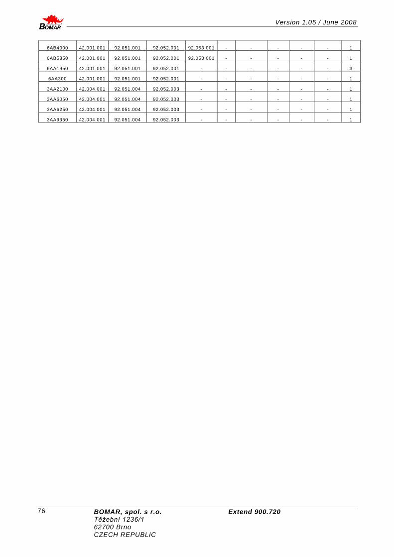
Version 1.05 / June 2008
BOMAR, spol. s r.o. Extend 900.720 Těžební 1236/1 62700 Brno CZECH REPUBLIC
76
6AB4000 42.001.001 92.051.001 92.052.001 92.053.001 - - - - - 1
6AB5850 42.001.001 92.051.001 92.052.001 92.053.001 - - - - - 1
6AA1950 42.001.001 92.051.001 92.052.001 - - - - - - 3
6AA300 42.001.001 92.051.001 92.052.001 - - - - - - 1
3AA2100 42.004.001 92.051.004 92.052.003 - - - - - - 1
3AA6050 42.004.001 92.051.004 92.052.003 - - - - - - 1
3AA6250 42.004.001 92.051.004 92.052.003 - - - - - - 1
3AA9350 42.004.001 92.051.004 92.052.003 - - - - - - 1

Version 1.05 / June 2008
BOMAR, spol. s r.o. Extend 900.720 Těžební1236/1 62700 Brno CZECH REPUBLIC
77
25. Výkresy sestav pro objednání náhradních dílů / Zeichnungen für Bestellung der Ersatzteile / Drawing assemblies for spare parts order
Při objednávání náhradních dílů vždy uvádějte: typ stroje (např. STG 120), výrobní číslo (např. 125) a rok výroby (např. 1999).
In die Bestellung der Ersatz teile führen Sie immer an: Maschinentyp (z. B. STG 120), Serien Nr. (z. B. 125) und Baujahr (z. B. 1999).
For spare parts order, you must always to allege: type of machine (for example STG 120), serial number (for example 125) and year of construction (for example 1999).

Version 1.05 / June 2008
BOMAR, spol. s r.o. Extend 900.720 Těžební 1236/1 62700 Brno CZECH REPUBLIC
78
25.1. Pásová pila / Bandsäge / Band saw

Version 1.05 / June 2008
BOMAR, spol. s r.o. Extend 900.720 Těžební1236/1 62700 Brno CZECH REPUBLIC
79
Poz. Objednací číslo Název položky ks
Pos. Bestell - Nr. Bezeichnung Menge
Pos. Reference No.
Item
Pcs.
1 201.6130-100 Rozvaděč / Schaltschrank / Switchboard 1
2 201.6201-100 Podstavec / Untergestell / Pedestal 1
3 201.6203-100 Svěrák / Schraubstock / Vice 1
4 201.6204-100 Rameno / Arm / Arm 1
5 201.6207-500 Válec zvedací / Hebezylinder / Lifting cylinder 2
6 201.6214-020 Odměřování ramene / Rahmenabmesung / Admeasurement of arm
1
7 201.6217-100 Třískový vynašeč / Spanaustrager / Swarf conveyor 1
8 201.6218-100 Rošt / Gitter / Hake 1
9 30.6114-154 Kryt / Deckel / Cover 1
10 30.6214-156 Kryt / Deckel / Cover 1

Version 1.05 / June 2008
BOMAR, spol. s r.o. Extend 900.720 Těžební 1236/1 62700 Brno CZECH REPUBLIC
80
25.2. Podstavec / Untergestell / Pedestal

Version 1.05 / June 2008
BOMAR, spol. s r.o. Extend 900.720 Těžební1236/1 62700 Brno CZECH REPUBLIC
81
Poz. Objednací číslo Název položky ks
Pos. Bestell - Nr. Bezeichnung Menge
Pos. Reference No. Item Pcs.
1 201.6206-100 Chlazení / Kühlung / Cooling 1
2 30.6101-105 Držák / Halter / Holder 1
3 30.6101-106 Držák / Halter / Holder 1
4 30.6101-108 Vzpěra 1
5 30.6101-109 Trubka 1
6 30.6110-111 Držák / Halter / Holder 1
7 30.6114-131 Kryt / Deckel / Cover 1
8 30.6114-134 Kryt / Deckel / Cover 1
9 30.6114-136 Držák / Halter / Holder 1
10 30.6201-101 Podstavec / Untergestell / Pedestal 1
11 30.6201-102 Sloup / Säule / Pillar 1
12 30.6201-103 Sloup / Säule / Pillar 1
13 30.6201-104 Nosnik / Stütze / Support 1
14 90.001.25.016 Šroub / Schraube / Screw 6x12 DIN 912 8,8
4
15 90.001.25.031 Šroub / Schraube / Screw 8x25 DIN 912 10
16 90.001.25.033 Šroub / Schraube / Screw 8x25 DIN 912 8,8
41
17 90.001.25.060 Šroub / Schraube / Screw M12x40 DIN 912
8
18 90.001.25.092 Šroub / Schraube / Screw M16x60 DIN 912
18
19 90.011.27.012 Šroub zápustný/ Countersunk screw / Senkschraube M8x16
6
20 95.800.019 Pojistný kroužek / Sicherungsring / Retaining ring 12
21 99.200.070 Vedení lieární / Führung / Linear guiding HGR35R-1560 1
22 99.200.072 Vedení lieární / Führung / Linear guiding HGR35R-1650 1

Version 1.05 / June 2008
BOMAR, spol. s r.o. Extend 900.720 Těžební 1236/1 62700 Brno CZECH REPUBLIC
82
25.3. Rameno / Arm / Arm

Version 1.05 / June 2008
BOMAR, spol. s r.o. Extend 900.720 Těžební1236/1 62700 Brno CZECH REPUBLIC
83
Poz. Objednací číslo Název položky ks
Pos. Bestell - Nr. Bezeichnung Menge
Pos. Reference No.
Item
Pcs.
1 201.2115-200 Regulace tlaku svěráku /Spandruckregulierung/Vice pressure regulation 1
2 201.6205-100 Pohon / Antrieb / Drive 1
3 201.6208-100 Napínání / Spannung / Stretching 1
4 201.6210-050 Vedení pásu / Bandführung / Band guiding 1
5 201.6214-250 Kartáček / Bürste / Brush 1
6 201.6707-400 Válec napínání / Zylinder / Cylinder 1
7 30.1814-011 Držák ventilu / Ventilhalter / Valve holder 1
8 30.6014-109 Pant / Türband / Hinge 6
9 30.6014-110 Deska / Platte / Plate 6
10 30.6114-123 Podpěra / Stütze / Support 1
11 30.6114-124 Podpěra / Stütze / Support 1
12 30.6114-146 Držák kluzáku / Prismahalter /Glider holder/ 1
13 30.6114-147 Držák / Halter / Holder 2
14 30.6114-160 Clona / Schürze / Shield 1
15 30.6204-101 Rameno / Arm / Arm 1
16 30.6214-119 Kryt / Deckel / Cover 1
17 30.6214-124 Kluzák / Prisma / Glider 1
18 30.6214-125 Kryt / Deckel / Cover 1
19 30.6214-128 Kryt / Deckel / Cover 1
20 30.6214-131 Dveře 1 / Tür / Door 1
21 30.6214-132 Dveře / Tür / Door 1
22 30.6214-133 Kryt / Deckel / Cover 1
23 30.6214-135 Kryt energií 1/ Energiedeckel / Cover leading 1
24 30.6214-136 Kryt pásu / Banddeckel / Band cover 1
25 30.6214-139 Držák / Halter / Holder 1
26 30.6214-140 Plech krytu 2/ Deckelblech / Metal plate cover 1
27 90.001.25.032 Šroub / Schraube / Screw 8x20 DIN 912 8,8 22
28 90.001.25.033 Šroub / Schraube / Screw 8x25 DIN 912 8,8 4
29 90.001.25.048 Šroub / Schraube / Screw M10x30 DIN 912 8,8 14
30 90.001.25.093 Šroub / Schraube / Screw 8
31 90.005.55.007 šroub se šestihrannou hlavou / Sechskantschraube / Hex head screw M8x28 4
32 90.011.27.005 Šroub zápustný/ Countersunk screw / Senkschraube M6x12 2
33 90.100.55.005 Matice / Mutter / Nut M8 DIN 934 4
34 90.150.50.005 Podložka / Scheibe / Washer d8,4 DIN 125 10
35 94.012.001 Rukojeť / Griff / Handle 2
36 94.012.002 Kryt / Deckel / Cover 4
37 94.202.002 Redukce / Reduktion / Reduction G1/4-6 2
38 99.100.003 Pant / Türband / Hinge 2
39 99.100.004 Pant / Türband / Hinge D13-00 2
40 99.170.001 Řetěz energii / Kabelschlepper / Cable tug 36x75/R-100 1
41 99.170.021 Řetěz energii / Kabelschlepper / Cable tug 6204 1
42 99.201.011 Vozík / Wagen / Carriage HGW35CC 4
43 99.260.003 Ventil kulovy / Kugelventil / Ball valve .1/4 1

Version 1.05 / June 2008
BOMAR, spol. s r.o. Extend 900.720 Těžební 1236/1 62700 Brno CZECH REPUBLIC
84
25.4. Svěrák / Schraubstock / Vice

Version 1.05 / June 2008
BOMAR, spol. s r.o. Extend 900.720 Těžební1236/1 62700 Brno CZECH REPUBLIC
85
Poz. Objednací číslo Název položky ks
Pos. Bestell - Nr. Bezeichnung Menge
Pos. Reference No. Item Pcs.
1 201.6207-100 Válec / Zylinder / Cylinder 1
2 30.6103-005 Držák / Halter / Holder 1
3 30.6103-105 Kostka / Würfel / Cube 1
4 30.6203-001 Čelist pevná / Feste Backe / Fixed jaw 1
5 30.6203-102 Čelist pohyblivá / Bewegliche Backe / Movable jaw
1
6 30.6203-104 Lišta / Leiste / Listel 2
7 30.6203-108 Konzola / Konsole / Console 1
8 30.6203-109 Podstavec / Untergestell / Pedestal 1
9 30.6203-110 Lišta / Leiste / Listel 1
10 30.6203-111 Doraz / Anschlag / Length stop 1
11 90.001.25.048 Šroub / Schraube / Screw M10x30 DIN 912 26
12 90.001.25.057 Šroub / Schraube / Screw M12x25 DIN 912 1
13 90.001.25.060 Šroub / Schraube / Screw M12x40 DIN 912 5
14 90.001.25.063 Šroub / Schraube / Screw M12x60 DIN 912 8,8
6
15 90.001.25.074 Šroub / Schraube / Screw M16x45DIN 912 8,8
12
16 90.001.25.086 Šroub / Schraube / Screw M16x40 DIN 912 4
17 90.005.55.025 šroub se šestihrannou hlavou / Sechskantschraube / Hex head screw M10x30
1
18 90.100.55.006 Matice / Mutter / Nut M10 DIN 934 1
19 90.150.50.007 Podložka / Scheibe / Washer d13 DIN 125 1

Version 1.05 / June 2008
BOMAR, spol. s r.o. Extend 900.720 Těžební 1236/1 62700 Brno CZECH REPUBLIC
86
25.5. Pohon / Antrieb / Drive

Version 1.05 / June 2008
BOMAR, spol. s r.o. Extend 900.720 Těžební1236/1 62700 Brno CZECH REPUBLIC
87
Poz. Objednací číslo Název položky ks
Pos. Bestell - Nr. Bezeichnung Menge
Pos. Reference No.
Item
Pcs.
1 30.1804-005 Podložka / Scheibe / Washer 1
2 30.4304-018 Ventilátor / Ventilator / Ventilator 1
3 30.6205-101 Hřídel / Welle / Shaft 1
4 30.6205-102 Příruba / Flansche / Flange 1
5 30.6205-103 Kroužek / Ring / Ring 1
6 30.6205-105 Víko / Deckel / Cover 1
7 30.6205-106 Kroužek distanční / Distanzring / Distance ring 1
8 30.6205-107 Víko / Deckel / Cover 1
9 30.6305-109 Pero / Feder / Feather 2
10 30.7504-007 Kolo / Umlenkrad / Wheel 1
11 90.001.25.019 Šroub / Schraube / Screw M6x25 DIN 912 8,8 6
12 90.011.27.040 Šroub / Schraube / Screw M16x35 1
13 91.001.104 Elektromotor / Elektromotor / Electromotor 5,5kW 1LA 7130-4AA-B5 1
13 91.001.070 Elektromotor / Elektromotor / Electromotor 7,5kW 1LA7133-4AA61 1
14 91.015.100 Ventilátor / Ventilator / Ventilator 1
15 95.300.018 Ložisko / Lager / Bearing 32217A 2
16 95.830.037 Gufero / Dichtung / Sealing 100x120x12 1
17 95.830.039 Gufero / Dichtung / Sealing 1
18 95.850.012 Matice / Mutter / Nut d17 1
19 95.855.011 Podložka / Scheibe / Washer d17 1
20 95.860.001 Hlavice mazací/Schmierkopf/Nipple 1
21 99.001.050 Převodovka / Getriebe / Gearbox VFR185 1
22 99.710.013 Spojka / Konjunktion / Conjuction 85x125 1

Version 1.05 / June 2008
BOMAR, spol. s r.o. Extend 900.720 Těžební 1236/1 62700 Brno CZECH REPUBLIC
88
25.6. Válec zvedací / Hebezylinder / Lifting cylinder

Version 1.05 / June 2008
BOMAR, spol. s r.o. Extend 900.720 Těžební1236/1 62700 Brno CZECH REPUBLIC
89
Poz. Objednací číslo Název položky ks
Pos. Bestell - Nr. Bezeichnung Menge
Pos. Reference No. Item Pcs.
1 30.0807-008 Držák / Halter / Holder 1
2 30.0807-009 Čep / Bolzen / Pivot 1
3 30.2807-004 Píst / Kolben / Piston 1
4 30.4107-003 Víko / Deckel / Cover 1
5 30.4707-206 Držák / Halter / Holder 1
6 30.6007-007 Čep / Bolzen / Pivot 1
7 30.6207-001 Válec zvedací / Hubzylinder / Lift cylinder 1
8 30.6207-002 Pístnice / Kolbenstange / Piston rod 1
9 30.6707-103 Přívod / Zufuhr / Inflow 1
10 90.001.25.032 Šroub / Schraube / Screw 8x20 DIN 912 1
11 90.101.55.007 Matice / Mutter / Nut M20x1,5 1
12 92.002.001 Šroubení / Schraubung / Screwing G 1/4" 2
13 92.151.001 Ventil pojistný / Sicherungsventil / Retaining valve
VPNH1_4 1
14 95.800.007 Pojistný kroužek / Sicherungsring / Retaining ring
d16 2
15 95.801.009 Pojistný kroužek / Sicherungsring / Retaining ring
d52 1
16 95.801.018 Pojistný kroužek / Sicherungsring / Retaining ring
d50 2
17 96.001.013 O-kroužek / O Ring / O Ring 45x2 2
18 96.002.007 O-kroužek / O Ring / O Ring 16x2 1
19 96.041.003 Manžeta / Manschette / Sleeve 601-28x36x7.1 1
20 96.060.003 Kroužek stírací / Abstreifring / W iping ring d28 1
21 96.082.002 Kroužek těsnící / Dichtungsring / Sealing ring 13/17 2
22 96.084.001 Kroužek vodící / Führungsring / Guiding ring 50x5.5x2.5x146 1
23 96.900.001 Těsnění kombinované / Dichtung / Sealing combinated
50x39x4 1

Version 1.05 / June 2008
BOMAR, spol. s r.o. Extend 900.720 Těžební 1236/1 62700 Brno CZECH REPUBLIC
90
25.7. Napínání pilového pásu / Sägebandspannung / Saw band stretching

Version 1.05 / June 2008
BOMAR, spol. s r.o. Extend 900.720 Těžební1236/1 62700 Brno CZECH REPUBLIC
91
Poz. Objednací číslo Název položky ks
Pos. Bestell - Nr. Bezeichnung Menge
Pos. Reference No. Item Pcs.
1 30.6208-003 Čep / Bolzen / Pivot 1
2 30.6208-004 Šroub / Schraube / Screw 1
3 30.6208-102 Kostka / Würfel / Cube 1
4 30.6708-301 Třmen / Steigbügel / Stirrup 1
5 30.6708-303 Držák / Halter / Holder 1
6 30.6708-304 Doraz / Anschlag / Length stop 1
7 30.7508-001 Napínání / Spannung / Stretching 1
8 30.7508-003 Lišta / Leiste / Listel 2
9 30.7508-004 Lišta / Leiste / Listel 2
10 30.7508-005 Kroužek / Ring / Ring 1
11 30.7508-006 Kolo / Umlenkrad / Wheel 1
12 30.7508-007 Čep / Bolzen / Pivot 1
13 30.7508-011 Víčko / Deckel / Cover 1
14 90.001.25.007 Šroub / Schraube / Screw M5x10 DIN 912 2
15 90.001.25.009 Šroub / Schraube / Screw M5x16 DIN 912 2
16 90.001.25.040 Šroub / Schraube / Screw M8x60 DIN 912 1
17 90.001.25.065 Šroub / Schraube / Screw M12x80 DIN 912 8
18 90.011.27.027 Šroub / Schraube / Screw M8x20 DIN 7991 6
19 90.012.50.006 Šroub / Schraube / Screw M4x25 DIN 84 2
20 90.350.0Z.004 Pružina / Feder / Spring 50x25,4x3 DIN 2093 A
12
21 91.173.007 Koncový spínač / Endschalter / Limit switch RIWK 1
22 95.001.053 Kuličkové ložisko / Kugellager / Ball bearing 6317A 2
23 95.801.033 Pojistný kroužek / Sicherungsring / Retaining ring
d180 DIN 472 2

Version 1.05 / June 2008
BOMAR, spol. s r.o. Extend 900.720 Těžební 1236/1 62700 Brno CZECH REPUBLIC
92
25.8. Vedení pásu / Sägebandführung / Saw band guiding

Version 1.05 / June 2008
BOMAR, spol. s r.o. Extend 900.720 Těžební1236/1 62700 Brno CZECH REPUBLIC
93
Poz. Objednací číslo Název položky ks
Pos. Bestell - Nr. Bezeichnung Menge
Pos. Reference No.
Item
Pcs.
1 201.6210-100 Kostka vodící L/ Führungsklotz / Guiding Cube 1
2 201.6210-200 Kostka vodící P/ Führungsklotz / Guiding Cube 1
3 201.6210-300 Kostka / Würfel / Cube 2
4 201.6816-100 Regulace řezu / Schnittdruckregulation / Pressure regulation 2
5 30.1503-006 Kladka / Rolle / Pulley 4
6 30.6010-315 Trubička / Rohr / Tube 2
7 30.6016-002 Deska / Platte / Plate 2
8 30.6110-110 Šroub / Schraube / Screw 1
9 30.6110-115 Doraz / Anschlag / Length stop 1
10 30.6210-051 Držák / Halter / Holder 1
11 30.6210-052 Pás pilový / Band / Band 1
12 30.6210-053 Trubka / Rohr / Tube 2
13 30.6210-054 Víko / Deckel / Cover 2
14 30.6210-055 Vodící lišta / Führungsleiste / Guiding listel 1
15 30.6210-056 Čep / Bolzen / Pivot 2
16 30.6210-057 Čep / Bolzen / Pivot 2
17 30.6210-058 Podložka / Scheibe / Washer 2
18 30.6210-059 Kostka / Würfel / Cube 1
19 30.6210-060 Vodící lišta / Führungsleiste / Guiding listel 1
20 30.6210-061 Šroub / Schraube / Screw 1
21 30.6210-062 Podložka / Scheibe / Washer 4
22 30.6210-063 Píst / Kolben / Piston 2
23 30.6210-064 Třecí deska / Bremsklotz / Frictional plate 2
24 30.6210-065 Držák / Halter / Holder 1
25 30.6210-068 Podložka / Scheibe / Washer 4
26 30.6310-002 Lišta / Leiste / Listel 1
27 30.6310-052 Podložka / Scheibe / Washer 2
28 30.9010-003 Držák / Halter / Holder 2
29 90.001.25.007 Šroub / Schraube / Screw M5x10 DIN 912 1
30 90.001.25.018 Šroub / Schraube / Screw M6x20 DIN 912 16
31 90.001.25.031 Šroub / Schraube / Screw 8x16 DIN 912 2
32 90.001.25.032 Šroub / Schraube / Screw 8x20 DIN 912 2
33 90.001.25.038 Šroub / Schraube / Screw M8x50 DIN 912 2
34 90.001.25.052 Šroub / Schraube / Screw M10x50 DIN 912 4
35 90.001.25.054 Šroub / Schraube / Screw M10x60 DIN 912 8
36 90.001.25.061 Šroub / Schraube / Screw M12x45 DIN 912 4
37 90.001.25.087 Šroub / Schraube / Screw M5x14 DIN 912 2
38 90.002.2D.007 Šroub / Schraube / Screw M5x16 DIN 913 4
39 90.002.2D.036 Šroub / Schraube / Screw 8x40 DIN 913 4
40 90.005.55.006 Šroub / Schraube / Screw M6x12 DIN 933 1
41 90.100.55.005 Matice / Mutter / Nut M8 DIN 934 4
42 90.150.50.005 Podložka / Scheibe / Washer d8,4 2
43 90.163.00.003 Podložka / Scheibe / Washer M12 D19,5 4
44 91.173.007 Koncový spínač / Endschalter / Limit switch 1
45 92.003.001 Šroubení / Schraubung / Screwing RSW-08LR 2

Version 1.05 / June 2008
BOMAR, spol. s r.o. Extend 900.720 Těžební 1236/1 62700 Brno CZECH REPUBLIC
94
46 95.001.006 Kuličkové ložisko / Kugellager / Ball bearing 6002 2RS 8
47 95.001.023 Kuličkové ložisko / Kugellager / Ball bearing 6302 2RS 1
48 95.800.019 Pojistný kroužek / Sicherungsring / Retaining ring d52 2
49 95.801.005 Pojistný kroužek / Sicherungsring / Retaining ring d40 2
50 95.860.001 Hlavice mazací/Schmierkopf/Nipple KM5 2
51 96.042.001 Manžeta těsnící / Afschlag / Cuf 40x30x8 K606 2
52 96.082.002 Kroužek těsnící / Dichtungsring / Sealing ring 13/17 2

Version 1.05 / June 2008
BOMAR, spol. s r.o. Extend 900.720 Těžební1236/1 62700 Brno CZECH REPUBLIC
95

Version 1.05 / June 2008
BOMAR, spol. s r.o. Extend 900.720 Těžební 1236/1 62700 Brno CZECH REPUBLIC
96
25.9. Kartáček / Bürste / Brush
Poz. Objednací číslo Název položky ks
Pos. Bestell - Nr. Bezeichnung Menge
Pos. Reference No. Item Pcs.
1 30.0814-204 Kolečko / Rolle / Wheel 1
2 30.6114-105 Deska / Platte / Plate 1
3 30.6114-119 Kroužek / Ring / Ring 2
4 30.6114-128 Držák / Halter / Holder 1
5 30.6214-251 Hřídel / Welle / Shaft 1
6 31.1506-115 Pružina / Feder / Spring 1
7 31.2107-206 Pružina / Feder / Spring 2
8 49.250.017 Kartáček / Bürste / Brush 1
9 90.001.25.067 Šroub / Schraube / Screw M8x80 DIN 912 8,8 2
10 90.001.25.095 Šroub / Schraube / Screw M8x70 DIN 912 8,8 1
11 90.002.2D.003 Šroub / Schraube / Screw M5x6 3
12 90.100.55.005 Matice / Mutter / Nut M8 DIN934 1
13 90.100.55.007 Matice / Mutter / Nut M12 DIN 934 1
14 90.150.50.007 Podložka / Scheibe / Washer d13 DIN 125 1
15 95.001.006 Kuličkové ložisko / Kugellager / Ball bearing 6000 2RS 2

Version 1.05 / June 2008
BOMAR, spol. s r.o. Extend 900.720 Těžební1236/1 62700 Brno CZECH REPUBLIC
97
25.10. Levá vodící kostka / Linker Führungsklotz / Left guiding cube

Version 1.05 / June 2008
BOMAR, spol. s r.o. Extend 900.720 Těžební 1236/1 62700 Brno CZECH REPUBLIC
98
Poz. Objednací číslo Název položky ks
Pos. Bestell - Nr. Bezeichnung
Menge
Pos. Reference No. Item Pcs.
1 30.6210-103 Deska / Platte / Plate 1
2 30.6210-101 Kostka L / Würfel / Cube 1
3 30.6710-108 Kolík / Bolzen / Pin 1
4 30.6710-109 Píst / Kolben / Piston 1
5 30.6710-110 Kroužek / Ring / Ring 1
6 30.7510-104 Držák / Halter / Holder 1
7 30.7510-114 Držák / Halter / Holder 1
8 30.7510-118 Kostka / Würfel / Cube 1
9 90.001.25.018 Šroub / Schraube / Screw 8x30 4
10 90.001.25.046 Šroub / Schraube / Screw 10x20 DIN 912 8,8 2
11 90.004.2D.002 Šroub / Schraube / Screw 6x12 DIN 915 1
12 90.005.55.007 šroub se šestihrannou hlavou / Sechskantschraube / Hex head screw M8x30 1
13 90.015.30.003 Šroub / Schraube / Screw M10x25 1
14 90.100.55.005 Matice / Mutter / Nut M8 DIN 934 1
15 90.154.50.003 Podložka / Scheibe / Washer 10x16x0,5 DIN 988 2
16 90.350.OZ.005 Talířová pružina / Tellerfeder / Belleville spring 20x10,2x1,1 8
17 95.001.044 Kuličkové ložisko / Kugellager / Ball bearing 609 2RS 2
18 95.801.035 Pojistný kroužek / Sicherungsring / Retaining ring d16 1

Version 1.05 / June 2008
BOMAR, spol. s r.o. Extend 900.720 Těžební1236/1 62700 Brno CZECH REPUBLIC
99
25.11. Pravá vodící kostka / Rechter Führungsklotz / Right guiding cube

Version 1.05 / June 2008
BOMAR, spol. s r.o. Extend 900.720 Těžební 1236/1 62700 Brno CZECH REPUBLIC
100
Poz. Objednací číslo Název položky ks
Pos. Bestell - Nr. Bezeichnung
Menge
Pos. Reference No. Item Pcs.
1 30.6210-103 Deska / Platte / Plate 1
2 30.6210-201 Kostka P / Würfel / Cube 1
3 30.6710-108 Kolík / Bolzen / Pin 1
4 30.6710-109 Píst / Kolben / Piston 1
5 30.6710-110 Kroužek / Ring / Ring 1
6 30.7510-104 Držák / Halter / Holder 1
7 30.7510-114 Držák / Halter / Holder 1
8 30.7510-118 Kostka / Würfel / Cube 1
9 90.001.25.018 Šroub / Schraube / Screw 8x30 4
10 90.001.25.046 Šroub / Schraube / Screw 10x20 DIN 912 8,8 2
11 90.004.2D.002 Šroub / Schraube / Screw 6x12 DIN 915 1
12 90.005.55.007 šroub se šestihrannou hlavou / Sechskantschraube / Hex head screw M8x30 1
13 90.015.30.003 Šroub / Schraube / Screw M10x25 1
14 90.100.55.005 Matice / Mutter / Nut M8 DIN 934 1
15 90.154.50.003 Podložka / Scheibe / Washer 10x16x0,5 DIN 988 2
16 90.350.OZ.005 Talířová pružina / Tellerfeder / Belleville spring 20x10,2x1,1 8
17 95.001.044 Kuličkové ložisko / Kugellager / Ball bearing 609 2RS 2
18 95.801.035 Pojistný kroužek / Sicherungsring / Retaining ring d16 1

Version 1.05 / June 2008
BOMAR, spol. s r.o. Extend 900.720 Těžební1236/1 62700 Brno CZECH REPUBLIC
101

Version 1.05 / June 2008
BOMAR, spol. s r.o. Extend 900.720 Těžební 1236/1 62700 Brno CZECH REPUBLIC
102
Je dodán na přání. Ist nach dem Wunsch geliefert.Is delivered by request.
25.12. Třískový vynašeč / Späneförderer / Swarf conveyor
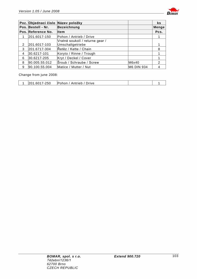
Version 1.05 / June 2008
BOMAR, spol. s r.o. Extend 900.720 Těžební1236/1 62700 Brno CZECH REPUBLIC
103
Poz. Objednací číslo Název položky ks
Pos. Bestell - Nr. Bezeichnung Menge
Pos. Reference No. Item Pcs.
1 201.6017-150 Pohon / Antrieb / Drive 1
2 201.6017-103 Vratné soukolí / returne gear / Umschaltgetriebe 1
3 201.6717-304 Řetěz / Kette / Chain 8
4 30.6217-101 Koryto / Rinne / Trough 1
6 30.6217-205 Kryt / Deckel / Cover 1
8 90.005.55.012 Šroub / Schraube / Screw M6x40 2
9 90.100.55.004 Matice / Mutter / Nut M6 DIN 934 4
Change from june 2008:
1 201.6017-250 Pohon / Antrieb / Drive 1

Version 1.05 / June 2008
BOMAR, spol. s r.o. Extend 900.720 Těžební 1236/1 62700 Brno CZECH REPUBLIC
104
25.13. Pohon třískového vynašeče / Antrieb von Späneförderer / Drive

Version 1.05 / June 2008
BOMAR, spol. s r.o. Extend 900.720 Těžební1236/1 62700 Brno CZECH REPUBLIC
105
Poz. Objednací číslo Název položky ks
Pos. Bestell - Nr. Bezeichnung Menge
Pos. Reference No. Item Pcs.
1 30.1502-465 Podložka / Scheibe / Washer 1
2 30.6017-203(220) Hřídel / Welle / Shaft 1
3 30.6017-206 Deska / Platte / Plate 1
4 30.6017-207 Deska / Platte / Plate 1
5 30.6017-208 Řetěz / Kette / Chain 2
6 30.6017-209 Hřídel / Welle / Shaft 1
7 30.6017-211 Kolo / Umlenkrad / Wheel 1
8 30.6017-212 Kolo / Umlenkrad / Wheel 1
9 30.6017-213 Kryt / Deckel / Cover 1
10 30.6017-214 Kryt / Deckel / Cover 1
11 30.6017-215 Kroužek distanční / Distanzring / Distance ring 1
12 30.6017-216 Skříň převodovky/ Schrank / Case 1
13 30.6017-218 Pero / Feder / Feather 1
14 49.200.027 Řetěz / Kette / Chain 1
15 90.001.25.018 Šroub / Schraube / Screw M6x20 DN 912 8,8 4
16 90.003.2D.010 Šroub stavěcí / Stellschraube / Setscrew M8x10 2
17 90.011.27.008 Šroub zápustný/ Countersunk screw / Senkschraube 10x20 1
18 95.001.009 Kuličkové ložisko / Kugellager / Ball bearing 6006 2RS 1
19 95.003.005 Ložisko / Lager / Bearing 6006AN 1
20 95.003.006 Ložisko / Lager / Bearing 6308AN 1
21 95.800.012 Pojistný kroužek / Sicherungsring / Retaining ring d25 1
22 95.800.013 Pojistný kroužek / Sicherungsring / Retaining ring d30 1
23 95.810.010 Pero těsné / Passfeder / Feather 10x8x40 3
24 95.810.016 Pero těsné / Passfeder / Feather 8x7x40 1
25 99.001.073(78) Převodovka / Getriebe / Gearbox VF49 L2 F2 60 P71 B14 B8 1

Version 1.05 / June 2008
BOMAR, spol. s r.o. Extend 900.720 Těžební 1236/1 62700 Brno CZECH REPUBLIC
106
25.14. Regulace tlaku svěráku /Spandruckregulierung/Vice pressure regulation

Version 1.05 / June 2008
BOMAR, spol. s r.o. Extend 900.720 Těžební1236/1 62700 Brno CZECH REPUBLIC
107
Poz. Objednací číslo Název položky ks
Pos. Bestell - Nr. Bezeichnung Menge
Pos. Reference No. Item Pcs.
1 30.1816-102 Hadice / Schlauch / Hose 2
2 30.2115-101 Kostka / Würfel / Cube 1
3 30.2116-008 Hadice / Schlauch / Hose 1
4 92.002.001 Šroubení / Schraubung / Screwing G1/4* 4
5 92.080.001 Manometr / Manometer / Manometer 1
6 92.154.001 Ventil / Ventil / Valve 1
7 94.204.005 Držák hadice / Schlauchhalter / Hose holder LBG 14/14-PP
2
8 96.082.002 Kroužek těsnící / Dichtungsring / Sealing ring CU 13/17
3

Version 1.05 / June 2008
BOMAR, spol. s r.o. Extend 900.720 Těžební 1236/1 62700 Brno CZECH REPUBLIC
108
25.15. Kostka / Klotz / Cube

Version 1.05 / June 2008
BOMAR, spol. s r.o. Extend 900.720 Těžební1236/1 62700 Brno CZECH REPUBLIC
109
Poz. Objednací číslo Název položky ks
Pos. Bestell - Nr. Bezeichnung Menge
Pos. Reference No.
Item
Pcs.
1 30.5910-106 Kostka / Klotz / Cube 1
2 30.6210-301 Podložka / Scheibe / Washer 2
3 30.7510-103 Čep dlouhý / 2
4 95.001.016 Kuličkové ložisko / Kugellager / Ball bearing 6203 2RS 6
5 95.850.004 Matice / Mutter / Nut KM3 2

Version 1.05 / June 2008
BOMAR, spol. s r.o. Extend 900.720 Těžební 1236/1 62700 Brno CZECH REPUBLIC
110
26. Umístění bezpečnostních značek / Verteilung der Sicherheitszeichen / Position of safety symbols
26.1. Pila / Bandsäge / Band saw

Version 1.05 / June 2008
BOMAR, spol. s r.o. Extend 900.720 Těžební1236/1 62700 Brno CZECH REPUBLIC
111
26.2. Napínací a hnací kolo / Umlenkrad und Antriebsrad / Tightening wheel and driving wheel
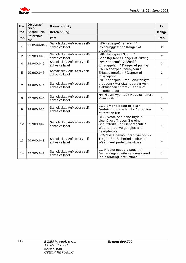
Version 1.05 / June 2008
BOMAR, spol. s r.o. Extend 900.720 Těžební 1236/1 62700 Brno CZECH REPUBLIC
112
Poz. Objednací číslo
Název položky
ks
Pos. Bestell - Nr. Bezeichnung Menge
Pos. Reference No.
Item
Pcs.
1 31.0599-005
Samolepka / Aufkleber / self-adhesive label
NS-Nebezpečí stlačení / Pressunggefahr / Danger of pressing
2
2 99.900.040 Samolepka / Aufkleber / self-adhesive label
NR-Nebezpečí říznutí / Schnittgefahr / Danger of cutting
2
4 99.900.042 Samolepka / Aufkleber / self-adhesive label
NV-Nebezpečí vtažení / Einzuggefahr / Danger of pulling
3
5 99.900.043 Samolepka / Aufkleber / self-adhesive label
NZ- Nebezpečí zachycení / Erfassunggefahr / Danger of interception
3
7 99.900.045 Samolepka / Aufkleber / self-adhesive label
NE-Nebezpečí úrazu elektrickým proudem / Verletzunggefahr vom elektrischen Strom / Danger of electric shock
1
8 99.900.046 Samolepka / Aufkleber / self-adhesive label
HV-Hlavní vypínač / Hauptschalter / Main switch
1
9 99.900.050 Samolepka / Aufkleber / self-adhesive label
SOL-Směr otáčení doleva / Drehrichtung nach links / direction of rotation left
2
12 99.900.047 Samolepka / Aufkleber / self-adhesive label
OBS-Noste ochranné brýle a sluchátka / Tragen Sie eine Schutzbrille und Gehörschutz / Wear protective googles and headphones
1
13 99.900.048 Samolepka / Aufkleber / self-adhesive label
PO-Noste pevnou pracovní obuv / Tragen Sie Sicherheitsschuhe / Wear fixed protective shoes
1
14 99.900.049 Samolepka / Aufkleber / self-adhesive label
CZ-Přečíst návod k použití / Bedienungsanleitung lesen / read the operating instructions
1
Copyright © 2022 FDOKUMEN