
expression: t:t180 ++oA *46:
6
Attempt onll' (5) questions Ql) A: l'he inductance of a moving-iron ammeter with a full scale deflection of 90o at 1.5A is given by the expression: t:t180 ++oA *46: -F3)rrH Where 0 is the angular deflection in radians fiom zero position. Determine (i) The spring constant. (ii) The angular deflection of the pointer for a current of LOA Ql) B: Define the follori,ing terms: l. Loading effect. 2. Resolution. 3. Span.4. Sensitivity. 5. Range. (6 Marks) (6 Marks) Q2) A: A PMMC ammeter has the following specifications: Coil dimension are lcmxlcm. Spring constant is 0.15x10⁻⁶ NmlratJ. Flux densiry is 1.5x10⁻³ublm2 Determine the no. of turns required to produce a deflection of 900 rvhen a current ZmA flows the coil. Q2) B: 'Ihe fbllowing readings were recorded for voltage Calculate the following: ( l) Arithmetic mean. (l) Average dcr iation. (5) \'ariance. (6 Marks) measurement: (8.2, 7.5, 8.2, 6.5, '7.5, 8.2. 6.5. 7._s, and 8.3), (2) Deviation ffom the mean. (4) Standard deviation (6) Probable enor. Q3) A: Answer the following: l. What are the errors usually occur in dynamometer type instruments? 2. Horv the electrical measuring instruments are classified? Q3) B: Design an Aryton shunt to provide an ammeter with current ranges of 1A, 5A, l0A and 20A. with an internal resistance of 50Q and a full scale deflection curent of lmA is to be used. (6 Marks) (6 Marks) A basic meter (6 Marks) Q4) A: In a certain dynamometer ammeter the mutual inductance M varies rvith deflection 0 (expressed in degree) as: M = - 8 cos (0 + 30") mH. Find the deflecting torque produced by a direct currenr of 60 mA corresponding to a deflection of60 o. Q4) B: Answer the following: (6 Marks) l. What are the functions of the two springs that used in the permanent magnet type moving coil instruments? 2. What are the sources of error in moving-iron instruments? (6 Marks) P.T.P Ministry of Higher E,ducation & Scientilic Research [.lniversitl of Technologl' l,aser & Optoelectronic Eng. Dcpartment Branch: Laser & Optoelectronics Eng. Class: 2nd Year Subj ect: N4easurements Final Exarnination Tinre: I 80 nrinutes Dare: .lune 2016 Examiner: Assist. Lecturer. Saad Z. Sekhi Code: LE2209 &.OPE2204 Academic Y ear 20 | 5-2016
-
Upload
khangminh22 -
Category
Documents
-
view
5 -
download
0
Transcript of expression: t:t180 ++oA *46:

Attempt onll' (5) questions
Ql) A: l'he inductance of a moving-iron ammeter with a full scale deflection of 90o at 1.5A is given by the
expression: t:t180 ++oA *46: -F3)rrHWhere 0 is the angular deflection in radians fiom zero position.
Determine (i) The spring constant.
(ii) The angular deflection of the pointer for a current of LOA
Ql) B: Define the follori,ing terms: l. Loading effect. 2. Resolution. 3. Span.4. Sensitivity. 5. Range.
(6 Marks)
(6 Marks)
Q2) A: A PMMC ammeter has the following specifications:
Coil dimension are lcmxlcm. Spring constant is 0.15x10⁻⁶ NmlratJ. Flux densiry is 1.5x10⁻³ublm2
Determine the no. of turns required to produce a deflection of 900 rvhen a current ZmA flows the coil.
Q2) B: 'Ihe fbllowing readings were recorded for voltage
Calculate the following:
( l) Arithmetic mean.
(l) Average dcr iation.
(5) \'ariance.
(6 Marks)
measurement: (8.2, 7.5, 8.2, 6.5, '7.5, 8.2. 6.5. 7._s, and 8.3),
(2) Deviation ffom the mean.
(4) Standard deviation
(6) Probable enor.
Q3) A: Answer the following:
l. What are the errors usually occur in dynamometer type instruments?
2. Horv the electrical measuring instruments are classified?
Q3) B: Design an Aryton shunt to provide an ammeter with current ranges of 1A, 5A, l0A and 20A.
with an internal resistance of 50Q and a full scale deflection curent of lmA is to be used.
(6 Marks)
(6 Marks)
A basic meter
(6 Marks)
Q4) A: In a certain dynamometer ammeter the mutual inductance M varies rvith deflection 0 (expressed in degree) as:
M = - 8 cos (0 + 30") mH. Find the deflecting torque produced by a direct currenr of 60 mA corresponding to a
deflection of60 o.
Q4) B: Answer the following:(6 Marks)
l. What are the functions of the two springs that used in the permanent magnet type moving coil instruments?
2. What are the sources of error in moving-iron instruments?
(6 Marks)
P.T.P
Ministry of Higher E,ducation & Scientilic Research[.lniversitl of Technologl'l,aser & Optoelectronic Eng. DcpartmentBranch: Laser & Optoelectronics Eng.Class: 2nd YearSubj ect: N4easurements
Final ExarninationTinre: I 80 nrinutesDare: .lune 2016Examiner: Assist. Lecturer. Saad Z. SekhiCode: LE2209 &.OPE2204Academic Y ear 20 | 5-2016
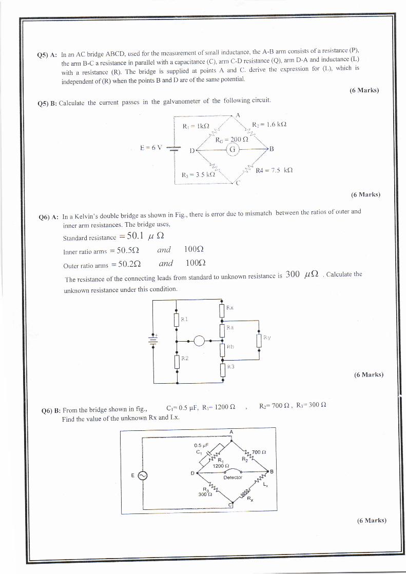
e5) A: In an AC bridge ABCD, used for the measurement of sr.r.rall inductance, the A-B ann consists of a resistance (P)'
the arm B-C a resistance in parallel with a capacitance (c), arm c-D resistance (Q), arm D-A and inductance (l-)
with a resistance (R). The bridge is supplied at points A and C. derive tlte expression for (L), which is
independent of (R) when the points B and D are of the same potential'
(6 Marks)
Q5) B: Calculate the current passes in the galvanometer of the following circuit'
Q6) A: In a Kelvin's double bridge as shown in
inner arm resistances. The bridge uses'
Standard resistance - 50.1 ft A
(6 Marks)
Fig., there is error due to mismatch between the ratios of outer and
lnner ratio arrns = 50.5e, and
outer ratio anns = 50.20 lnd100o
1 00o
The resistance of the connecting leads tiom standard to unknorvn resistance is 300 pO ' Calculate the
unknown resistance under this condition'
Ry
(6 Marks)
Q6) B: From the bridge shown in fig', Cr:0'5 pF' Rr: 1200 O
Find the value of the unknown Rx and Lx'
Rz:700 O, R3:300 Q
g
RX
RF)
KJ
(6 Marks)

!L^.1r....taJt
*-LWJ\i:L2016-2015 crr+lt or.i.yt i,ti*t dA )\D; ',L-.,f,(
C:0.15 x l0-6 Nm/rad
I =2 x 10-'A
0.15xl0-6x1.57 0.2355 x l0 -u
Ql) A:)f::_ - (40 _ 8e _ 3e21pH I rad
(i) da
= 40 -t|-t(+) = 40 -r2.s66 - 7.40r = 20 pH / rad
e- It'dL2C de
rT (l .5 )' xzuxr0-622CC = 14 .32 x 10-6 Nm / rad
for I: lA
e- I12dL (l)'x (40 - 80 - 30') = 1.008 rad = 57.802 C de 204.32 xl0-6)
(iD
Ql) B:
l. Loading effect: It's the change of circuit parameter, characteristic, or behaves due to instrumentoperation without maintains.
2. Resolution: The smallest change in input that the instruments can response to it, or the ratio ofoutput to smallest change in input.
3. span: It is algebraic difference of the upper and lower limits of the range.4. Sensitivity: It's represent the ratio of output signal to a change iriinput, or its represent the
response output of the instrument to a change of its input.5. Range: It is defined as that region enclosed by the limits within which a particular quantity is
measured.
Q2) A:
At Steady state condition T6: T.
A:(l x l0-2 x l" 10-2 ):lr l0-a m2
B:1.5 r l0-3 wb/m2
0=90s- 7T x90o=l.57rad180
BANI:CO
. ^r Ce.. _lv =-=
BAI 1.5 x 10-3 x 1 x 10-a x 2xl0-3 3x10-ro=785.

I lr', .a,l3' o=jT, =
F ln @)'ln-l
= 10.71'
Q3) A: (1)
l. Frictional Error'2. TemPerature error'
3. Enoi due to stray magnetic field'
4. Frequency error'
5. Enor due to eddY currents
(2) l. Absolute Instruments
2. SecondarY Instruments
I. Indicating Instruments
ll' Recording lnstruments
Ill. lntegration lnstruments
Q3) B:
p __ I,R. = I,R! = ,to,.t,orl, = o.o5efisit't = LJ, It- 1,,
^l-lxlo-'1- R^ 50 x l0-'
Rrr, = it--, - \= ffi-= o'olc)
P = Jt!--= to ! to,
]-u = o'oo5 Qnsr,:-jr_1, l0_lxl0-'
F = I'R'' = to i to'l-- = o'0025 f)
Asr,4 - j^_l^ Z0-lxl0-'
3(0.6) * 3(0.1) * 2(1'1) * (0.7)= 0.55Volt .
- 68 '4 = 7 .6volt '9
Q2) B:I P,'x,
rY-L/'-I./L- SFL''2. d,= X,-V
3(8.2) + 3(7.s) + 2(6.s) + (8'3)
dt=8.2-7.6=0'6voltdq=7.5-7.6=-0'lvoltdt = 6.5 - 7 .6 = -l.lvoltds=8.3-7.6=0'7volt
8
6. r=t0.67456o
= 0.7Volt .
= !0.67456 (0.7) = +0.472192 VoltA
5. V =o2
6
v = 0.49V2

QA) A:
dMd0
8sin(d +30u)mH
+l =8sin(600 +300)=8sin 900 =8mH ldegreede le-.6o'
Ta = 12 Oy
=(60 x l0-t)t * 8 x l0 -3 = 28.8pNm"d0
QA) B:
(l) 1. Provides the control of the coil movement.2. Serve in leading the current in and out of the coil.3. They are spiraled in opposite direction in order to neutralize the effects of temperature changes.
(2) l. Error due to hysteresis in the iron parts of the moving system. This enor is eliminated by usingsmall iron parts with narrow hysteresis loop, which neglect hysteresis losses.
2. Error due to stray fields. This emor can be removed by using magnetic shielding (usingcovering case ofcast iron).
3. Error due to change in frequency. Change in frequency produces:i. Change in the impedance of the coil.ii. Change in the magnitude of the eddy curents.
Qs) A: ?, ?+?-e Zj
Zr tj --?-.?4Q. \
\R*rrL; li ''Ql;of,r5 + ff.
ft+s,/L(fu)=Pe( R+gw L) Rs = Pe (tU Rrc+r)
PRs *l'rtRs :( tr R.cP q *Pq
RRs = pg
R= PqRs
L= qPq
=PQ
aRp
urLRs=tRsq_Pe
I,6 )
IRtQ5) B:
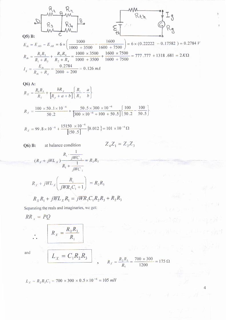
E,n=Eao-Eou=ur[-#r, 1600 ) -I = 6 x (0.22222 - 0.17582 ) = 0.2784 V
1600 + 7500 )
, R,R, , Rr.Ro _ 1000 x 3500K =-+---tn R, + R" R" + R, looo + 35oo
1600 x 7500
R, + R, R, + Ro 1000 + 3500 1600 + 7500
E,n 0.2784= 0.126 mAI^ =+=
R.,. + R..,n * Rs 2000 + 200
=777.777 + 1318.681 =ZK{l
Q6) A:
o"=+.#;rn{+;}- l00x50.lx10-6 50.5x300x10-6 l.too 100'l"x- 50.2 'pooxl0-6+100+50.5llso.z 50.5J
Rx =99.8x10-o * l5llO--x-19-6
{o.orz}=l0t x10-6o[l50.51
Q6) B: at balance condition
R,. I
(*" + jwL r'r+: ftzR3
R'+ iwc,
(n)R" * iWL *l :*; | = RrR,A r ^\jwnrc,+l)
ZoZ, = ZrZ,
R"R, + iWL xR, = iWRrCtR2R3 + R2R3
Separating the reals and imaginaries, we get:
RR, = PQ
and L" = C.R2R3=
RrR, _ 700 x 300 = 175 f)
Rl 1200RX
Ru = RtR,
^R,
L*: RrRrCt=700 x300 x0'5x10-6 =l05mH