Interpretive practice and redefining meaning in Harry Potter
Upload
khangminh22Category
view
2download
0
1
Exploring the Interpretive Potential of
Clovis Waste Flakes
Submitted by Nancy V. Littlefield,
To
The University of Exeter
as a dissertation for the degree of
Master of Philosophy in Archaeology
February 2015
This dissertation is available for Library use on the understanding that it is copyright
material and that no quotation from the dissertation may be published without proper
acknowledgement.
I certify that all material in this dissertation which is not my own work has been
identified and that no material has previously been submitted and approved for the
award of a degree by this or any other University.
(signed)

2
Abstract
This research examines the technology behind Clovis biface production
from Clovis manufacturing areas at the Gault Site, Texas, (41BL323), with specific
focus on flake striking platform preparation traits. Lithic analysts agree that
platform bearing flakes retain clues into knapping technologies (Andrefsky
2005:86). Clovis experts agree that Clovis knappers invested effort before
removing flakes by preparing platforms (Bradley, et al. 2010:66; Morrow 1995) for
exerting control during biface manufacture, including mastering control of overshot
flaking (Bradley 2010:466). Evidence shows that Clovis knappers were highly
skilled in their craft and preferred high quality raw materials to manufacture their
tools and frequently produced overshot flakes. While basic manufacturing traits
are present, Clovis represents a complex bifacial reduction technology (Bradley, et
al. 2010:64). The data here elucidates differences in the application of reduction
techniques used by Clovis. These data reveal no set pattern in the application of
platform preparation traits used by Clovis knappers, but identified trends in the use
of preparing platforms in flake types and phases that highlight Clovis biface
reduction sequences, which may have followed a systematic ‘template.’ Therefore,
a consistent approach may have been used to produce Clovis bifaces, but
individual platform preparation traits were not. In addition to this study, a
supplemental study was conducted concerning the intentionality of Clovis overshot
flaking. This separate study revealed these flakes regularly exhibit the removal of
stacks, hinges, deep flake scars and other error traits. As such, overshot flakes
were a technique that served a dual purpose of removing errors while
simultaneously thinning the biface. This research has contributed to a greater
understanding of Clovis biface technology reduction processes and flake removal
techniques used at the Gault Site.

3
Table of Contents
Abstract....................................................................................................................... 2
Table of Contents........................................................................................................ 3
List of Figures ............................................................................................................ 11
List of Tables ............................................................................................................. 20
Acknowledgements .................................................................................................. 24
Chapter 1 – Clovis Culture and Clovis Technology ................................................... 30
Clovis- An Early Paleoindian Fluted Point Culture ................................................ 30
Clovis Sites............................................................................................................. 33
The Clovis Phenomenon ....................................................................................... 36
The State of Clovis Research ................................................................................. 38
Clovis Biface Technology ....................................................................................... 40
Biface Production .................................................................................................. 43
Experimental Flintknapping and Understanding Clovis Technology .................... 44
Clovis Biface Production Flakes ............................................................................ 55
Striking Platforms .................................................................................................. 57
Overshot Terminations: Flake Type or Technique? .................................................. 59
Chapter 2 -- Exploring the Interpretive Potential of Clovis Waste Flakes ................ 65

4
Chapter 3 -- Debitage Analysis ................................................................................. 72
Flakes or Debitage? ............................................................................................... 72
Debitage Analysis – What Flakes Can Tell Us ....................................................... 72
Chapter 4 -- The Gault Site ....................................................................................... 78
Geology of Texas and the Gault Site ..................................................................... 80
Physiographic Setting ........................................................................................ 80
Regional Geology and the Texas Landscape ..................................................... 82
Local Geology and Soils ..................................................................................... 86
Gault History and Excavations .................................................................................. 89
Henry Gault’s Farm ............................................................................................ 89
Gault Site Excavations ....................................................................................... 89
1991 Olmstead Excavation of Area 1 ................................................................ 93
1998 Salvage Excavation (Areas 7 and 8) .......................................................... 94
1999-2002 Excavation Highlights (Areas 2-14) ................................................. 95
2007-2013 Excavation of Area 15 ..................................................................... 96
Gault Geomorphology .............................................................................................. 97
Chapter 5 – Area 4 Excavations (Study Area) ......................................................... 100
Chapter 6 -- Methodology ...................................................................................... 105
Sampling Methods .............................................................................................. 106

5
Data Collection .................................................................................................... 108
Measuring Striking Platforms .......................................................................... 109
Striking Platform Preparation Traits ............................................................... 110
Measuring Flake Dimensions .......................................................................... 114
Analytical Phases of Clovis Biface Reduction .................................................. 118
Statistical Methods .......................................................................................... 120
Chapter 7 -- Clovis Flake Study Results and Analysis ............................................. 124
Descriptive Statistics of All Flakes ....................................................................... 124
Analysis of Clovis Biface Flakes -- Refining the Data Set ........................................ 128
Biface Flake Metrics ........................................................................................ 128
Biface Platform Metrics ...................................................................................... 131
Differentiating Between Biface Thinning Flakes and Biface Shaping/Thinning
Flakes .............................................................................................................................. 138
Analysis of Flake Type Frequencies by Phase ..................................................... 143
Analysis of Flake Terminations ........................................................................... 145
Termination by Phase ...................................................................................... 145
Termination by Type ....................................................................................... 148
Analysis of Lipping on Platforms ......................................................................... 149
Lipping by Phase .............................................................................................. 149
Lipping by Type ................................................................................................ 151

6
Analysis of Striking Platform Attributes and Traits ............................................. 156
Analysis of Platform Grinding by Phase .......................................................... 156
Analysis of Grinding Combinations by Type .................................................... 158
Presence or Absence of Grinding .................................................................... 160
Platform Status ................................................................................................... 167
Analysis of Remnant /Shattered/Crushed Platforms ...................................... 167
Rem/Shattered/Crushed by Phase .................................................................. 167
Rem/Shattered/Crushed by Type ................................................................... 168
Analysis of Plain Platforms .................................................................................. 170
Plain Platforms by Phase ................................................................................. 170
Plain Platforms by Type ................................................................................... 171
Analysis of Cortical Platforms ............................................................................. 172
Cortical Platforms by Phase ............................................................................ 172
Cortical Platforms by Type .............................................................................. 173
Statistical Analysis of Platform States (Platform Status/Condition) ................... 174
Analysis of Platform Shape ................................................................................. 175
Shape by Phase ................................................................................................ 175
Shape by Type ................................................................................................. 177
Analysis of Platform Preparation Traits .............................................................. 178

7
Preparation by Phase ...................................................................................... 179
Preparation by Type ........................................................................................ 181
Platform Preparation Correlation Analysis ......................................................... 182
Platform Preparation Complexity by Score ........................................................ 184
Analysis of Platform Preparation Scores ............................................................ 184
Preparation Scores By Phase ........................................................................... 184
Preparation Scores by Type ............................................................................. 186
Analysis of Platform Complexity – Preparation Traits in Flake Types by Phase . 188
BFS Flakes by Trait and Phase ......................................................................... 189
BfST Flakes by Trait and Phase ........................................................................ 190
BFT Flakes by Trait and Phase ......................................................................... 191
Platform Complexity of ET/Ch Flakes by Trait and Phase ............................... 192
Analysis of Platform Complexity in Flakes with Overshot Terminations (OST)
..................................................................................................................................... 194
OST by Phase ................................................................................................... 194
OST by Type ..................................................................................................... 195
OST Platform Preparation Score ..................................................................... 197
Qualifying the Typical Clovis Thinning Flake ....................................................... 198
Qualitative Analysis of Clovis Flakes ................................................................... 200
Chapter 8 – Clovis Flake Study Discussion .............................................................. 207

8
Clovis Biface Flake Technology ........................................................................... 207
Biface Platform Metrics ................................................................................... 208
Differentiating Biface Shaping Flakes and Biface Thinning Flakes .................. 210
Biface Flake Analysis by Flake Type and Phase ............................................... 211
Flake Terminations .......................................................................................... 214
Lipping on Platforms ....................................................................................... 214
Ground Platforms – Degree of Grinding ......................................................... 215
Platform State/Status ...................................................................................... 216
Plain and Cortical Platforms ............................................................................ 216
Platform Shape ................................................................................................ 217
Platform Preparation by Phase and Flake Type .............................................. 218
Platform Complexity Score ..................................................................................... 219
Platform Scores on Flakes with Overshot Terminations ................................. 221
Assessment of the Typical Clovis Biface Thinning Flake ................................. 222
Hypotheses Testing ................................................................................................ 223
Hypothesis 1 .................................................................................................... 223
Hypothesis 2 .................................................................................................... 224
Clovis Flake Study -- Summary in Wider Context ............................................... 225
Clovis Flake Study --Discussion ........................................................................... 231

9
Chapter 9 – ............................................................................................................. 234
SUPPLEMENTAL RESEARCH SECTION ..................................................................... 234
Chapter 9 – Exploring the Duplicity of the Clovis Overshot Flake (OSF) and the
Question of Intentionality ............................................................................................... 235
9.1 – OSF Introduction ........................................................................................ 235
Exploring the Intentionality of Overshot Flaking Techniques ......................... 236
9.2 – OSF Study Methodology ............................................................................ 237
9.2.1 – OSF -- Data Collection .......................................................................... 237
9.3 – OSF Study Hypothesis ................................................................................ 239
9.4 – OSF Study – Exploring Overshot Intentionality .......................................... 239
9.5 – OSF Study -- Results and Analysis .............................................................. 240
9.5.1 -- OSF Platform Scores ............................................................................ 240
9.6 – OSF Platform and Margin Preparatory Measures and Quantifying OS Flake
Errors ............................................................................................................................... 242
9.6.1 – OSF – Analysis of Whole OSF Flakes .................................................... 246
9.6.2 – OSF – Analysis of OS Flakes with Bifacially Flaked Margins ................ 246
9.6.3 – OSF – Square Edge Removals on OS flakes. ........................................ 247
9.6.4 – OSF -- Statistical Analysis ..................................................................... 248
9.6.5 – OSF -- Qualitative Analysis................................................................... 250
9.7 – OSF Discussion ........................................................................................... 253

10
9.8 – OSF Hypothesis Testing .............................................................................. 256
9.8.1 -- OSF Supplement Study Discussion ......................................................... 257
9.9 -- OSF Supplement Study Summary Conclusion ........................................... 258
Chapter 10 -- Future Research and Overall Summary Conclusion ......................... 259
Future Research .................................................................................................. 259
Final Conclusion .................................................................................................. 260
Appendix 1 - Flake and Platform Data Collection Form ........................................ 263
Appendix 2 – Clovis Biface Flake ............................................................................ 264
Appendix 3 – Terms and Terminology .................................................................... 266
Bibliography ............................................................................................................ 270

11
List of Figures
Figure 1— Lost or discarded Clovis spear points from the Gault Site, Texas,
(41BL323): (a) & (c) have severe thermal damage; (b) is a Clovis basal fragment;
(d) & (e) have unretouched minor damage; (f)-(i) depict various states of heavy
reworking. (Used with permission from the Gault School of Archaeological
Research (GSAR), photos by Sergio Ayala).......................................................... 31
Figure 2 – An engraved limestone from the Gault Site, Texas, (41BL323)
(Photo by M. Samuel Gardner, used with permission from the GSAR) ................. 32
Figure 3-- United States map with highlighted overlay of the Great Plains
province and section (Trimble 1980) and depicts primary Clovis sites in and around
the Southern High Plains region (Collins 1998a:85; 2007:74) (Color overlay of
Great Plains is modified from Trimble 1980. Used with permission from the U.S.
Geological Survey, Dept. of the Interior U.S.G.S., U.S. Geological Survey).......... 34
Figure 4 -- A large, abandoned, early/middle phase Clovis biface from the
Gault Site, Texas, (41BL323). Note the overshot flake scar in the center of the
biface (Spec. # UT-1040-103) (Photo by M. Samuel Gardner, used with permission
from the Gault School of Archaeological Research). ............................................. 41
Figure 5– Successful refitting of a Clovis Blade core #17P1-13 from the
Pavo Real Site, Texas (41BX52) (Composite photo adapted from Collins and Link
2003:162-173). ...................................................................................................... 46
Figure 6 – Recent refitting attempts were successful of two large Clovis
overshot flakes recovered from the Gault Site, Texas, 41BL323. .......................... 48
Figure 7— Abandoned Clovis point from the Gault Site, Texas (41BL323)
with visible overshot flake or full-face scar (Spec# UT-1040-113) (Photo by M.

12
Samuel Gardner, used with permission from the Gault School of Archaeological
Research). ............................................................................................................. 50
Figure 8– Schematic illustration of possible Clovis biface flaking options. (1
& 6) shaping flakes (2) opposed alternating diving flaking; (3) overshot flake (4)
longitudinal thinning or channel flake; (5) full face flake; (sensu Bradley, et al.
2010:65). ............................................................................................................... 52
Figure 9 – Clovis point recovered from the Gault Site, Texas, (41BL323)
exhibiting a flute or longitudinal thinning scar on the basal edge (Spec # UT 2624-
1). (Photo courtesy of the Gault School of Archaeological Research) .................. 54
Figure 10 – A Clovis overshot flake from Area 4 at the Gault Site, Texas,
(41BL323). Arrows point to a hinge scar (right lateral edge) that was likely caused
by longitudinal thinning during the middle phase of biface reduction (Spec # UT-
4384-4) .................................................................................................................. 56
Figure 11 -- Illustration depicting complex platform preparation traits on a
Clovis biface margin (Adapted from Bradley, et al. 2010:67)................................ 59
Figure 12 – Simplified schematic showing the possible mass removal
differences between a plunging flake and an overshot flake. ................................ 61
Figure 13— A discarded proximal fragment of a Clovis preform from the
Gault Site, Texas (41BL323) exhibiting evidence of a catastrophic plunging flake
failure caused by longitudinal thinning. The shaded area is a reconstruction of the
missing distal portion. (Photo by M. Samuel Gardner, and used with permission
from the Gault School of Archaeological Research) .............................................. 62

13
Figure 14— Drawing of a failed Clovis overshot flake that ruined a biface.
Inset is probable reconstruction of original size of biface. (Drawn from Spec. No.
UT-1154-15). ......................................................................................................... 63
Figure 15 -- The location of the Gault Site (41BL323) relative to the Texas
State Capital of Austin, U.S. .................................................................................. 79
Figure 16 – Basic chronology of Central Texas Archaeology (sensu Collins
2004:101-126. ....................................................................................................... 80
Figure 17— Edwards Plateau region relative to the Southern High Plains
(Color overlay of Great Plains is modified from Trimble 1980. Used with
permission from the U.S. Geological Survey, Dept. of the Interior U.S.G.S., U.S.
Geological Survey). ............................................................................................... 81
Figure 18—Edwards Plateau and Coastal Plains (sensu Collins 2002) ...... 82
Figure 19— Composite illustration showing the Cordilleran and Ouachita
Orogenic belts and their relevance to the Western Interior Seaway shown at its
most extensive point. These events respectively helped formed the geology of the
Great Plains, as well as the Central Texas Region of the Edwards Plateau (The
extent of the WIS is based sensu amplo on Cobban and McKinney, 2013, U.S.
Geological Survey, Dept. of the Interior/USGS) .................................................... 83
Figure 20– Illustration showing the formative association between the
Edwards Plateau, the Balcones Escarpment, and the Balcones Fault Zone, which
trend along the buried Ouachita-Marathon mountain belt axes and its relevance to
the Gault Site (sensu Collins 2002). ...................................................................... 85

14
Figure 21– Basic schematic of the bedrock geology at the Gault Site.
(Graphic used with permission from the Gault School of Archaeological Research.
Illustration by D. Clark Wernecke). ........................................................................ 87
Figure 22– Topographic illustration of the Gault Site and excavation areas
since 1991. (Map graphic used with permission from the Gault School of
Archaeological Research). .................................................................................... 88
Figure 23-- H. B Ramsaur (left) and crew (top & bottom right) trenching into
the Gault Site middens (circa 1929). (Photos J.E. Pearce Manuscript Collection,
used with permission from the Texas Archaeological Research Laboratory, Univ. of
Texas at Austin and the GSAR). ........................................................................... 91
Figure 24—Re-construction of a Clovis Alibates point reported as found
between two incised limestone pebbles from the Gault Site, Texas (41BL323).
(Photo reconstruction by M. Samuel Gardner based on 2003 photo re-creation by
Peter Bostrom, Lithic Casting Lab, Troy, Illinois .
(http://lithiccastinglab.com/gallery-pages/gaultstackcachelarge.htm). ................... 93
Figure 25 – Block designations for excavations at the Gault Site from 1991
through 2002 and their locality within the Buttermilk Creek Valley. (Mapping by
Ken Brown, Eddie De La Rosa, and Marc Beherec. Graphic provided courtesy of
the Gault School of Archaeological Research) ...................................................... 94
Figure 26 – Contour map of the Gault Site, Texas (41BL323) showing the
location of Area 4 within an alluvial fan. (Map used with permission from the Gault
School of Archaeological Research) ................................................................... 101
Figure 27—Area 4 Basic Excavation Grid ................................................ 102

15
Figure 28– Stratigraphic representation depicting general elevation of Clovis
stratum in Area 4. (Graphic Modified used with permission from the GSAR). .... 103
Figure 29-- Measuring striking platform depth (left) and striking platform
length (right) ........................................................................................................ 109
Figure 30 – Simple schematic of basic platform shapes ........................... 111
Figure 31 –Diagram of platform preparation traits on a biface margin prior to
the outlined area of flake is removed. Grinding is represented in dark gray
(adapted and modified from Bradley, et al. 2010:67). .......................................... 113
Figure 32– Profile drawing of a flake arrow indicates measurement of
thickest area of the flake body. ............................................................................ 114
Figure 33–Basic flake descriptions of the dorsal and ventral view of a Clovis
biface thinning flake from Area 4. The red arrows represent measurements taken
of the flake body at its widest and longest points. ............................................... 115
Figure 34-- Flake formation and terminations (sensu Cotterell and
Kamminga 1987). ................................................................................................ 117
Figure 35 – Flake scar characteristics of a Clovis end thinning or channel
flake ..................................................................................................................... 120
Figure 36 – Biface Flake Mean Dimensions of Whole Flakes L/W/Th by
Phase. ................................................................................................................. 130
Figure 37 -- Biface Flake Mean Dimensions of Whole Flakes (L/W/Th) (mm)
by Flake Type ...................................................................................................... 131
Figure 38 – Platform Metrics (mm) by Phase (n=1383) ............................ 133

16
Figure 39— Platform Metrics Platform Mean Dimensions (W/D) by flake type
(n-1383) ............................................................................................................... 134
Figure 40 – Box Plot Platform Dimensions (W/D) by Phase (n=1383) ...... 135
Figure 41– Box Plot Whole Flake Dimensions (L/W/Th) by Phase ........... 136
Figure 42—Distribution histograms for flake metric length, width, and
thickness. ............................................................................................................ 138
Figure 43 – Comparison of flake lengths and widths articulated as squares
to represent size of flake types -- biface shaping (BFS), biface thinning (BFT), and
biface thinning/shaping (BfST). ........................................................................... 142
Figure 44 -- Comparison of expressions of flake size ratios with magnitude
removed .............................................................................................................. 143
Figure 45 -- Comparison of Flake Types by Phase .................................. 144
Figure 46 -- Terminations by Phase .......................................................... 146
Figure 47 -- Terminations by Phase (w/ step/broken flakes removed) ...... 147
Figure 48 -- Terminations by Flake Type .................................................. 149
Figure 49 — Lipping by Phase ................................................................. 150
Figure 50 -- Lipping by Flake Type ........................................................... 151
Figure 51 -- Lipping on BFS Flakes by Phase .......................................... 153
Figure 52 -- Lipping on BfST Flakes by Phase ......................................... 154
Figure 53 -- Lipping on BFT Flakes by Phase .......................................... 155
Figure 54 -- Lipping on ET/Ch Flakes by Phase ....................................... 156

17
Figure 55—Platform Grinding Combinations by Phase ............................ 158
Figure 56 – Grinding Combinations by Type ............................................ 159
Figure 57 -- Presence/Absence of PF Grinding by Phase ........................ 161
Figure 58-- Presence/Absence of Grinding by Type ................................. 162
Figure 59 – PF Grinding on BFS Flakes by Phase ................................... 163
Figure 60 -- PF Grinding on BfST Flakes by Phase .................................. 164
Figure 61 – PF Grinding on BFT Flakes by Phase ................................... 165
Figure 62 -- PF Grinding on ET/Ch Flakes by Phase................................ 166
Figure 63 – Remnant/Shattered/Crushed Platforms by Phase ................. 168
Figure 64 -- Remnant, Shattered, or Crushed Platforms by Flake Type ... 169
Figure 65 -- Plain Platforms by Phase ...................................................... 171
Figure 66 -- Plain Platforms by Flake Type ............................................... 172
Figure 67 -- Cortical Platforms by Phase .................................................. 173
Figure 68 -- Cortical Platforms by Type .................................................... 174
Figure 69 -- Platform Shapes by Phase .................................................... 176
Figure 70 -- Platform Shape by Type ........................................................ 178
Figure 71 -- Platform Preparation by Phase ............................................. 180
Figure 72 -- Platform Preparation by Type ................................................ 182
Figure 73 -- Platform Scores by Phase ..................................................... 185
Figure 74 -- Platform Scores by Type ....................................................... 186

18
Figure 75 -- Mean Average Platform Score for Each Phase. (y axis =
average score) .................................................................................................... 187
Figure 76 -- Mean Average Platform Score for Each Type (y axis = average
score) .................................................................................................................. 188
Figure 77 – BFS Flakes --Platform Preparation Trait by Phase ................ 189
Figure 78 – BfST Flakes - Platform Preparation Traits by Phase ............. 191
Figure 79 – BFT Flakes – Preparation Traits by Phase ............................ 192
Figure 80 – (ET/Ch) Flakes –Platform Preparation Traits by Phase ......... 193
Figure 81 – Platform Preparation Traits on OS Terminations by Phase ... 195
Figure 82 – Platform Preparation on OS Terminations by Flake Type ..... 196
Figure 83 –flake platforms matching criteria of Bradley et al. (2010:66) ... 198
Figure 84 - Example of fine-grained “porcelain-like” subcortical material on a
Clovis Flake (Spec# BB-2113-19) ....................................................................... 202
Figure 85—Drawing of Clovis flake UT-4321-(G4) exhibiting a prominent
arris and multidirectional scars on the dorsal side and may represent manufacture
or maintenance debris associated with multidirectional biface flake cores described
as discoidal cores from Gault Clovis assemblage (Bradley, et al. 2010:58). ....... 203
Figure 86—Schematic of blade core tablet flakes (sensu Bradley, et al.
2010:19) .............................................................................................................. 205
Figure 87 – A Clovis biface thinning flake from Area 4 exhibiting a “rapidly
expanding” flake body in relation to a small striking platform. (Photo by M. Samuel
Gardner courtesy of the GSAR). ......................................................................... 209

19
Figure 88 – A large Clovis cortical flake from Area 4 exhibiting a “rapidly
expanding” flake body in relation to the small striking platform. .......................... 210
Figure 89 -- Schematic illustration depicting set up of striking platform as
well as preparing the opposite margin before removing the overshot flake (sensu
amplo Aubry, et al. 2008. Graphic by Tom Williams and Nancy Littlefield). ....... 245
Figure 90 – A unifacially flaked distal ‘point’ fragment recovered in situ from
Clovis deposits in Area 4. .................................................................................... 251
Figure 91 – Example of a Clovis overshot flake that removed, among other
issues, a hinge scar that runs parallel to the right lateral edge of the flake. ........ 253
Figure 92—Flake and Platform Data Collection Form .............................. 263
Figure 93 — Example of a ‘straight’ platform on a Clovis biface thinning
flake image is of the dorsal/obverse side of a striking platform that has been
ground, faceted, and isolated (UT-4509-58). The photo was taken with Amscope
MD400 20X. ........................................................................................................ 264
Figure 94—Microscopic Photo of ‘heavily ground’ Clovis platform. (Photo
taken with AmScope MD400 20X magnification)(Spec# UT-4470-8). ................. 264
Figure 95 — Heavy lipping on a Clovis flake (UT-4384-4). The platform
length measures 18.2 mm. .................................................................................. 265
Figure 96-- General Schematic of early, middle, and late Clovis biface
reduction phases used in this research ............................................................... 269

20
List of Tables
Table 1 -- Clovis Flakes Debitage and Debris from Area 4 ....................... 107
Table 2 -- Clovis General Debitage from Area 4 ....................................... 107
Table 3 -- Platform Attributes and Preparation Traits Recorded ............... 110
Table 4 – Coding used for Platform Lipping .............................................. 112
Table 5 – Coding for recording plain and cortical platforms ...................... 114
Table 6 – Flake condition and status ........................................................ 116
Table 7 – Percentages/Counts of Data Set by Flake Type (n= 2185) ....... 125
Table 8—Percentages/Counts of Data Set by Flake Phase (n=2185) ...... 126
Table 9 -- Descriptive Analysis of Platform Preparation Traits of All Flakes
(n=2185) .............................................................................................................. 127
Table 10 – Biface Flake Metrics of Whole Flakes -- Length/Width/Thickness
(n=1082) .............................................................................................................. 129
Table 11-- Biface Flake Metrics of Whole Flakes (L/W/Th) by Phase ....... 129
Table 12 – Biface Flake Metrics of Whole Flakes (L/W/Th) by Flake Type
............................................................................................................................ 130
Table 13 — All Platform Metrics (W/D) (n=1383) ...................................... 132
Table 14 – Platform Metrics (mm) by Phase (n=1383) ............................. 132
Table 15 – Platform Metrics (mm) by Flake Type (n=1383) ...................... 133
Table 16-- Platform Depth to Width Ratios by Flake Type (n=1383) ........ 137

21
Table 17 -- Shapiro-Wilk Goodness-of-Fit Test to confirm non-normal
distribution ........................................................................................................... 138
Table 18 -- Kruskal-Wallis test .................................................................. 139
Table 19 -- Tukey-Kramer HSD Analysis of Flake Length ........................ 140
Table 20 -- Tukey-Kramer HSD Analysis of Flake Width .......................... 140
Table 21 -- Size and Dimension Analysis by Flake Types ........................ 141
Table 22-- Summary of Flake Type by Phase (n=1510) ........................... 144
Table 23 -- Termination by Phase (n=1510) ............................................. 145
Table 24 -- Termination by phase – w/ step/broken flakes removed ........ 147
Table 25 --Terminations by Flake Type (n=1510) ..................................... 148
Table 26 – Lipping by Phase .................................................................... 150
Table 27 -- Lipping by Flake Type (n=1510) ............................................. 151
Table 28 -- Lipping on BFS Flakes by Phase ........................................... 152
Table 29 -- Lipping on BfST by Phase (n=184) ......................................... 153
Table 30 -- Lipping on BFT Flakes by Phase (n=894) .............................. 154
Table 31 – Lipping on ET/Ch Flakes by Phase ......................................... 155
Table 32 –Grinding Combinations by Phase n / % ................................... 157
Table 33 – PF Grinding Combinations by Type n / % ............................... 159
Table 34 -- Presence/Absence of Grinding by Phase (n=1510)................ 160
Table 35 -- Presence/Absence of PF Grinding by Type (n=1510) ............ 161
Table 36 -- Grinding on BFS by Phase (n=1510) ...................................... 163

22
Table 37 -- Grinding on BfST by Phase .................................................... 164
Table 38 – PF Grinding on Biface Thinning Flake by Phase (n=1510) ..... 165
Table 39 – PF Grinding on ET/Ch Flakes by Phase ................................. 166
Table 40 – Remnant/Shattered/Crushed Platforms by Phase .................. 168
Table 41 – Remnant/Shattered/Crushed Platforms by Type .................... 169
Table 42 -- Plain Platforms by Phase ....................................................... 170
Table 43 -- Plain Platforms by Flake Type ................................................ 171
Table 44 -- Cortical Platforms by Phase ................................................... 172
Table 45 -- Cortical Platforms by Type ..................................................... 173
Table 46 -- Chi-square Test of Platform State by Phase .......................... 174
Table 47 -- Chi-square Test of Platform State by Type............................. 175
Table 48 – Platform Shapes by Phase ..................................................... 176
Table 49 -- Platform Shape by Type ......................................................... 177
Table 50 -- Platform Preparation by Phase* ............................................. 179
Table 51 -- Platform Preparation by Type* ............................................... 181
Table 52 -- Platform Trait-Non-parametric Correlation Tests .................... 183
Table 53 -- Platform Scores by Phase ...................................................... 184
Table 54 -- Platform Scores by Type ........................................................ 186
Table 55 –BSF Flakes -- Platform Preparation Traits by Phase ............... 189
Table 56 -- BfST Flakes -- Platform Preparation Traits by Phase ............. 190
23
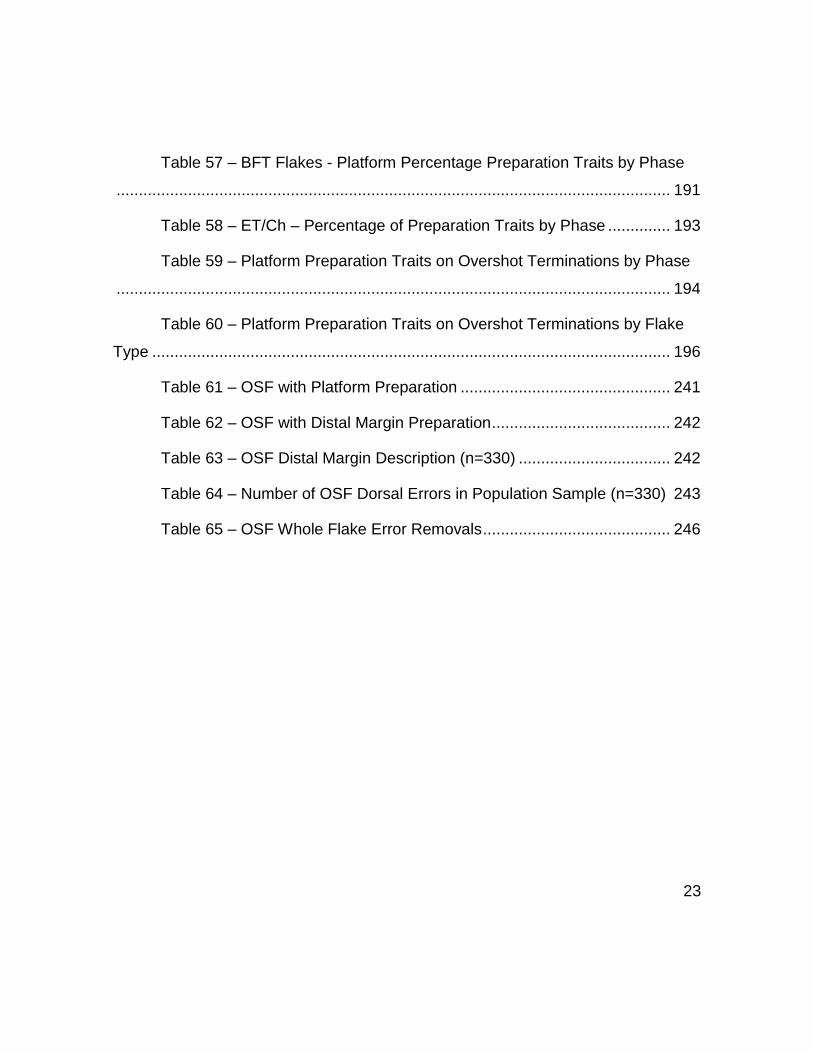
Table 57 – BFT Flakes - Platform Percentage Preparation Traits by Phase
............................................................................................................................ 191
Table 58 – ET/Ch – Percentage of Preparation Traits by Phase .............. 193
Table 59 – Platform Preparation Traits on Overshot Terminations by Phase
............................................................................................................................ 194
Table 60 – Platform Preparation Traits on Overshot Terminations by Flake
Type .................................................................................................................... 196
Table 61 – OSF with Platform Preparation ............................................... 241
Table 62 – OSF with Distal Margin Preparation ........................................ 242
Table 63 – OSF Distal Margin Description (n=330) .................................. 242
Table 64 – Number of OSF Dorsal Errors in Population Sample (n=330) 243
Table 65 – OSF Whole Flake Error Removals .......................................... 246

24
Acknowledgements
To my parents, James E. and Effie E. Velchoff for their love and for teaching
me to love life. Where to begin…
I want to first thank my supervisors Dr. Linda M. Hurcombe for her kindness;
encouragement and guidance throughout this research and to Bruce A. Bradley for
showing me the rocks and for all you do for your students to succeed. Thank you
for spending countless hours of personal time to teach me (and countless others)
about flintknapping. Much love and thanks goes to Cindy Bradley (Bruce’s wife) for
her hospitality, and for sharing their home in past years and for her reassuring
words.
I would not have begun such a journey were it not for the willingness of
Michael B. Collins who made me a part of the Gault team. I will never be able to
thank him enough for his kindness, patience, and for placing his confidence in my
ability to contribute to this project. Thanks for sharing your wisdom of geology and
archaeology as well as your keen grasp of puns. I am indebted to Clark Wernecke,
for boosting my morale by saying things like “aren’t you done yet?” But seriously,
for the incalculable hours in the field during those darker years when we were
dealing with so many hardships only to lose our dear Sam as well. Happier days
were ahead with symposiums, tours, & avoiding at all costs another clementine
incident. A special thanks goes to Clark’s wife, Mel Grzybowski & their children,
Honor, Arden, & K-9s Lily-pup, Clovis (weenie dog) & to Vicky, the St. Bernard for
the extra slobbers.
Thanks to the original Gault Staffers Marilyn Shoberg, Cinda Timperley and
Andy Hemmings, especially Sam Gardner who was the first to welcome me that

25
first day to Gault, which changed my life on the molecular level. He encouraged
me to seek higher education & he would be proud of where his advice has led. So,
to the love of his life Ann Nolen, and the Gardner family, this dissertation honors
his memory, which lives through many of the photographs and graphics used here.
I want to thank Dub Crook for advice, encouragement, and support needed
to complete this research.
To my field and lab cohorts: Sergio Ayala, the man, the myth thanks for lots
of good times, Robert Lassen, super-crime-fighter thanks for the 3:30pm chocolate
breaks and lots of good times. I am grateful to Dave Madsen for his help and
wisdom, encouraging with things like ‘get on with it’, but mostly thanks for letting
me share an office. Jennifer Gandy for everything she does, her clever gifts, and
keeping an eye on the place (lab). To Steve Howard & Reggie Byron, thank you
for being there when I needed help. To Jon Lohse & his charismatic (dry) sense of
humor, and Molly Morgan thanks for just being wonderful. Thanks to Ashley
Lemke for lots of laughs and everything Gault! Thanks to Anna Gilmer for help
with advice & geological references. Thanks to Toni Fischer, a wonderful gal, field
hand, & dear friend, plus her mom makes really good cake. Thanks to Jen & Troy
Anderson & Maeby for ‘babysitting’. To my dear friend Sabelyn Arden, thank you
for your love, friendship, and support.
I am so grateful to Dick Boisvert for years of friendship & support, and to
Deb Boisvert for sharing their beautiful home, good scotch, & lobster. Thanks To
the New Hampshire S.C.R.A.P. crew Kurt Masters, Heather Rockwell, Nathaniel
Kitchel, George LeDuc, Mike Malburne, Linda Feduerer, & many others, for
accepting me as one of their own. Special appreciation goes to the family of Wil
Maker; we share your sorrow for his loss as he is missed by all of us.

26
I am grateful to Doris and Howard Lindsey, and Ricky Lindsey and his wife
Ann, and the Lindsey clan for everything they have done and continue to do to help
with the Gault Site. None of this would have been possible without you. Immense
gratitude goes to Mike Johnson for his friendship, advice & flintknapping expertise
and Virginian archaeology. Likewise, respect to the Archeological Soc. of Virginia
& the usual suspects, Jean Teasdale, Cynthia Hansen, Vicki & George Monken,
Joan Cameron (btw, thanks for the mojo, it worked!), & (long-tall) Nancy Anthony.
Special thanks to C.D. Cox for his friendship & years volunteering at Gault. To the
Cox family, Steve & Petra, thanks for the pies! To the Gault regulars: O.K. Smith,
Celia Isbrecht, Jill Patton, Katie Sloan, Zack Windler, and Liz Sefton, & thousands
of volunteers a huge thank you to all. Much appreciation goes to Jonelle Miller-
Chapman & Frank Sloan for so many years of dedication & for cleaning up the
Area 8 materials. I am grateful to have known long-time supporter Roger DeYoung
who passed away too soon. To super-volunteer Sandy Peck for her absolute
enthusiasm of Gault.
I am grateful for the Texas Archeological Society & Dr. Harry Shafer for the
life-changing Archeology Academies that brought me to Gault. I am grateful to my
fellow GSAR board of directors, our Chair, Michael B. Collins, Harry Miller, Jon
Lohse, Elton Prewitt, Tim Brown, & Aubrey Holt for their encouragement & advice.
An exceptional thank you goes to Elton Prewitt for days and hours spent teaching
me about Texas ‘arrowheads’ and archaeology, please know you are a great
friend.
I am grateful for the generosity, love, and support of Howard and Gerrie
Crockett who helped me through very difficult times.

27
Special thanks to Bob Patten for taking time to visit & discuss fluting &
fracture mechanics, and his insightful flintknapping wisdom: the forked stick is
genius! I regret not having a chance to thank Tony Baker for sharing his
engineering insight of fracture mechanics of flintknapping. His passing left a huge
void for many. I want to thank Dennis Stanford for his sense of humor and keeping
archaeology moving forward. Thanks to Darrin Lowery for answering questions
and sharing his extensive geologic knowledge. I want to thank Dr. Thomas Hester
for personally taking time to write and send information regarding his experiences
at Gault. To the Texas Archeological Res. Lab (TARL) staff, especially Diane
Ruetz & Laura Nightengale, for allowing access to Elton Prewitt & other
archaeological artifacts.
I am grateful to the President, Dean, and faculty of Texas State University,
Dept. of Anthropology, and Dr. Britt Bousman for providing a home for the (Gault)
Prehistory Research Project (Go Cats!).
Big thanks to the Exeter crews: Caroline Jeffra, Ann Oldroyd, Danielle
Davies, Emily Hicks, Ciprian Ardelean, Antony Whitlock, Nada Khreisheh, Edward
Pearson, and Stefan Klemenik. To Stephanie Turnham & Directors of the Bell Co.
Museum for being our biggest fans. Thanks to Dr. Andy Speer his knowledge of
experimental flintknapping. Thanks to Dr. Nikos Papadopoulos for sharing his
knowledge of geophysics & to Ken and JoAnn Kvamme for sharing him with us. I
want to thank Dr. Jack Rink for working with me in the field and sharing his
expertise in the science of OSL. Thanks to Dr. Paul Goldberg for working with me
in the field and sharing his expertise in geosciences and geomorphology. Thanks
to the legendary Ernie Lundelius for sharing his extensive knowledge about Texas
geology and paleontology.

28
I want to thank John Jackson for contacting GSAR about the tusk in Temple,
Texas. Thanks to Matt Brown (and Ernie L.) at VP Lab @UT Austin, who did a
splendid job preserving the ‘Temple Tusk’ now on permanent display at Bell Co.
Museum in Belton. Thanks to the City of Temple, the Mayor & his wife, & city staff
for permission to salvage the tusk and to Center for Arch. Studies at TX State
University for helping with the Temple Tusk Project.
To the family of Skip Lohse, thanks for sharing him, he is missed. Thanks to
Paul Santarone for discussions of Clovis caches and flintknapping.
I am deeply indebted to the incredible Dr. Jill Urofsky DVM & staff at Animal
Care Clinic in Round Rock for saving the life of my best friend. I could not have
completed this research without CoCo! I am grateful for Jazzercise© and for their
instructors Rodney, Trish, Heather, & Patty because without it and them, I would
be dead or worse.
To Lindsey and Andy Williams, thank you for the love, and, oh, thanks for
introducing me to haggis and really good scotch! To my adorable, clever, and fun-
loving Pugs, CoCo ‘Monkee’ Chanel, and Napoleon ‘Bubba’ Bonapug, thanks for
making me laugh from my soul.
Finally, to the love of my life, Dr. Thomas J. Williams, thank you from the
bottom of my heart. You are my joy, my life and I am so glad we found each other.
I could not have gotten through any of this without your love, encouragement,
laughter, your smile, your wit… and yes, I will marry you!

29
This dissertation is dedicated
to the memory of
Merle Samuel Gardner

30
Chapter 1 – Clovis Culture and Clovis Technology
Clovis- An Early Paleoindian Fluted Point Culture
Clovis is an early North American Paleoindian flaked stone tool culture that
dates roughly to a time range of 13,250 to 12,800 cal yr B.P. (Waters and Stafford
2007). Clovis is a prolifically documented culture that is primarily characterized by
large, well-made, fluted lanceolate-shaped spear points (Bonnichsen and Turnmire
1991; 2005:1-26; Bradley 1991:369; Bradley, et al. 2010:56-106; Collins 1999a:46;
Meltzer 1993:293-310; 2004:123-161; 2009:64; Smallwood 2012; Waters et al.
2011a).
The Clovis fluted spear point is the defining feature of Clovis culture and
usually dominates most research studies related to Clovis habitation and kill-sites
(Boldurian and Cotter 1999, Frison and Todd 1986:136; Speer 2014). Extensive
data are available on Clovis points (Anderson, et al. 2010; Meltzer 1986:27)
including variation and morphology (Sholts, et al. 2012), and regional distribution
patterns (Hamilton, et al. 2013; Smallwood 2012).
However, with the exception of some Clovis caches, (Bamforth 2014:39;
Collins, et al. 2007:101-123; Frison and Bradley 1999; Jennings 2013; Waters and
Jennings 2015), many Clovis points can be problematic in that they are rarely
recovered in a pristine state. These are often incomplete or broken (Bradley, et al.
2010:56; Ferring 2001:130; Smallwood 2012), reworked to exhaustion, or severely
damaged (Fig.1) (Bradley, et al. 2010:56,102-04).

31
Figure 1— Lost or discarded Clovis spear points from the Gault Site, Texas, (41BL323): (a) & (c) have severe thermal damage; (b) is a Clovis basal fragment; (d) & (e) have unretouched minor damage; (f)-(i) depict various states of heavy reworking. (Used with permission from the Gault School of Archaeological Research (GSAR), photos by Sergio Ayala)
The Clovis tool kit has expanded considerably beyond the iconic fluted point
(Collins 2002; Ferring 2001:130; Haynes 1982:393) with the discovery of
macroblades at Blackwater Draw (Green 1963) as well as bone and ivory
technology (Bradley et al. 2010:114; Haynes 1993:219-236; Huckell 2007:110).
Artistic expressions (Fig. 2) of Clovis culture have also been conveyed as

32
delicately scored patterns on limestone pebbles and chert flake fragments (Collins
2002:37, 39; Haynes and Warnica 2012:6; Lemke, et al. 2015; Wernecke and
Collins 2012:120-121).
Figure 2 – An engraved limestone from the Gault Site, Texas, (41BL323) (UT-4801-6) (Photo by M. Samuel Gardner, used with permission from the GSAR)

33
Clovis Sites
Clovis sites have been found throughout North America and comprise a vast
geographic expanse that includes portions of Canada and the lower contiguous
United States, as well as portions of northern and central South America (Stanford
and Bradley 2012:31). In the early 1930s, the discovery of a large fluted point near
the town of Clovis, New Mexico (Howard 1935a; 1935b; Wormington 1957), led to
similar (Clovis) point discoveries in what is known as the Southern High Plains
region; a prominent geographic component of the Great Plains (Bradley 1991:369;
Holliday 1997:150-51).
The Clovis type-site of Blackwater Draw in New Mexico and similar sites,
e.g. the Dent Site in Colorado, the Lubbock Lake Site, Texas (Johnson 1987) and
the Miami Site also in Texas, are all located in and around the Southern High
Plains (Fig. 3) (Collins 1998a:85; 2007:74). The Southern High Plains remained
the focus of Paleoindian research early on (Hester, J. 1972; Holliday 1997:1-20)
and in later decades for supplemental studies (Boldurian and Cotter 1999; Haynes
and Warnica 2012:1-9; Holliday, et al. 1994:234-244).

34
Figure 3-- United States map with highlighted overlay of the Great Plains province and section (Trimble 1980) and depicts primary Clovis sites in and around the Southern High Plains region (Collins 1998a:85; 2007:74) (Color overlay of Great Plains is modified from Trimble 1980. Used with permission from the U.S. Geological Survey, Dept. of the Interior U.S.G.S., U.S. Geological Survey).
The early discovery of Clovis sites in the Southern High Plains were often
associated with extinct proboscidea remains and emergent evidence led many
scholars to mischaracterize (Saunders and Daeschler 1994:1) Clovis hunting
culture as nomadic super predators (Adovasio and Page 2002:124; Grayson and
Meltzer 2002:313-359; Mithen 2003:213). By the mid-1960s, an hypothesis of
“Clovis overkill” (Martin 1967) was advanced to explain the extinction of large
Pleistocene mammals, and argued their demise was not caused by dramatic
environmental or climatic changes. Instead it was proposed that Clovis hunters

35
wiped out not only the North American species of mammoth (M. columbi), but also
the majority of large Pleistocene carnivores and herbivores (Collins 2002:31-4;
Haynes 1982). One of the flaws with the ‘overkill’ hypothesis questions why only
some species died and others survived (Grayson and Meltzer 2003:586). Clovis
hunters may have been part of the problem, but the idea of human overkill on such
a massive scale was eventually found to be overstated based on evidence to the
contrary (Alford 1974; Grayson and Meltzer 2003:589; Frison 1986:114).
Many Paleoindian sites have been discovered in the Southern High Plains
region, which extends into the Central Texas region and the Edwards Plateau
(Holliday 1997:149-150). Central Texas Paleoindian sites have been found to
occur in deep sedimentary environments such as floodplains and valley fills
(Pertulla 2004:34; Driese, et al. 2012). Floodplains are ideal environments for
preserving archaeological sites in relative stasis (Goldberg and MacPhail 2006;
Mandel, et al. 2001:183).
One of the oldest Clovis sites in North America that dates to around 11,550
cal yr BP is the Aubrey Clovis Site in North Texas (see above Fig. 3). Construction
crews digging an outlet for a local reservoir exposed the site. Archaeologists
discovered well-preserved concentrations of Clovis-age artifacts buried seven to
nine meters below the floodplain of the Elm Fork of the Trinity River Drainage
Basin (Ferring 2001). Closer to Austin, Texas, construction work in the area
exposed the Wilson-Leonard Site (see above Fig. 3). Archaeologists recorded
multiple components, including Paleoindian deposits, which were buried under six-
meters of valley fill (Collins 1998a:26-32).
This section briefly highlights the historical significance of the earliest
discoveries of Clovis sites in and around the Southern High Plains region as well
36
as the vital role of geosciences in Paleoindian research around the Edwards
Plateau region in Central Texas.
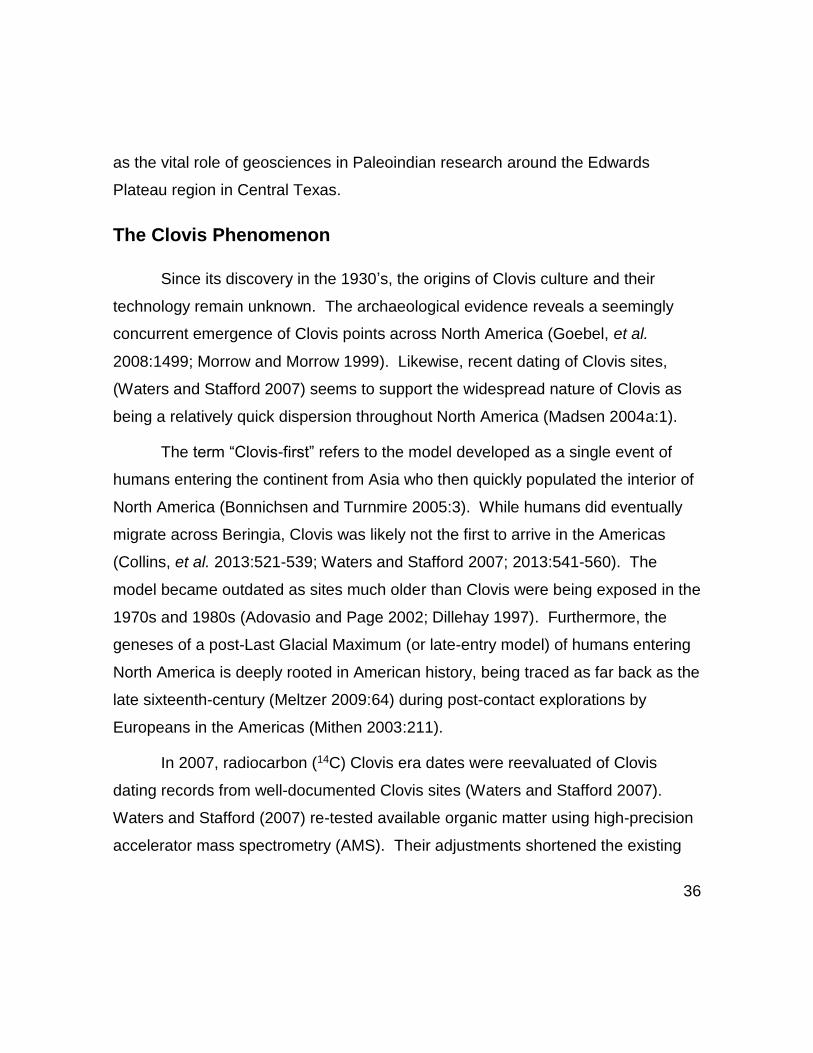
The Clovis Phenomenon
Since its discovery in the 1930’s, the origins of Clovis culture and their
technology remain unknown. The archaeological evidence reveals a seemingly
concurrent emergence of Clovis points across North America (Goebel, et al.
2008:1499; Morrow and Morrow 1999). Likewise, recent dating of Clovis sites,
(Waters and Stafford 2007) seems to support the widespread nature of Clovis as
being a relatively quick dispersion throughout North America (Madsen 2004a:1).
The term “Clovis-first” refers to the model developed as a single event of
humans entering the continent from Asia who then quickly populated the interior of
North America (Bonnichsen and Turnmire 2005:3). While humans did eventually
migrate across Beringia, Clovis was likely not the first to arrive in the Americas
(Collins, et al. 2013:521-539; Waters and Stafford 2007; 2013:541-560). The
model became outdated as sites much older than Clovis were being exposed in the
1970s and 1980s (Adovasio and Page 2002; Dillehay 1997). Furthermore, the
geneses of a post-Last Glacial Maximum (or late-entry model) of humans entering
North America is deeply rooted in American history, being traced as far back as the
late sixteenth-century (Meltzer 2009:64) during post-contact explorations by
Europeans in the Americas (Mithen 2003:211).
In 2007, radiocarbon (14C) Clovis era dates were reevaluated of Clovis
dating records from well-documented Clovis sites (Waters and Stafford 2007).
Waters and Stafford (2007) re-tested available organic matter using high-precision
accelerator mass spectrometry (AMS). Their adjustments shortened the existing

37
Clovis dates from 11,500 to 10,900 14C yr BP, to a revised time span of 11,050 to
10,800 14C yr BP (or 13,000 to 12,800 cal yr BP based on Calpal-online.de (2014)).
However, in 2013, Waters and Stafford (2013:541) presented an altered range of
13,000 to 12,600 cal yr BP without clear validation.
Obtaining accurate dates from established Clovis sites has been impaired
by deficient preservation and/or lack of organic matter and is a common problem
amongst many Paleolithic and Paleoindian sites (Collins 2002). The dates
reported by Waters and Stafford in 2007 were challenged as being problematic
(Haynes, et al., 2007) in that the data were insufficient to support the wide
dispersal of Clovis technology, even though Waters and Stafford (2007:1124)
contend that such a feat could have been achieved in as little as 200 years or less.
In addition to dating issues, there are problems correlating Clovis dates to
migration theories (Haynes 1964; Stanford and Bradley 2012:45). At best, the
timing of the earliest human migrations into North America is unclear and seem to
coincide with unpredictable glacial cycles, meltwater, and climate change (Stanford
1991:1-14). It is known that rapid changes to environments and climates were well
underway in North America by 16,500 cal yr BP (Reimer, et al. 2009:1122).
According to Mithen (2003), between 16,000 and 12,000 (cal yr BP), the North
American ice sheets had advanced at least four times (Mithen 2003:239), and at
one point reached as far south as the state of Iowa (Gwynne 1942:200-208).
However, around 13,000 cal yr BP, erratic glacial melt was interrupted by
the onset of the Younger Dryas cooling event (Bement and Carter 2008; Fiedel
2011; Holliday, et al. 2011; Mithen 2003:239; Straus and Goebel 2011). Glacial
and interglacial conditions in North America would have created chaotic
environmental conditions (Fiedel 2011; 2014:11) and as such, may not have
38
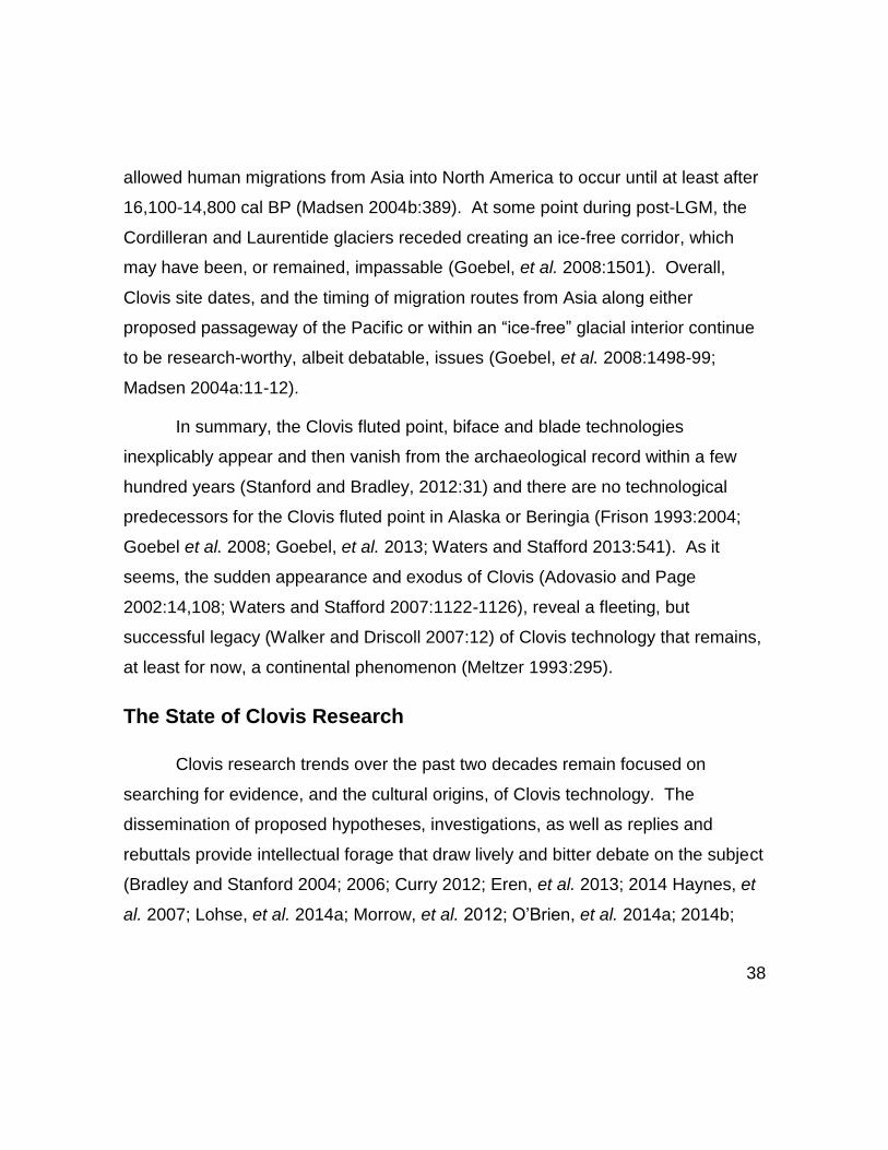
allowed human migrations from Asia into North America to occur until at least after
16,100-14,800 cal BP (Madsen 2004b:389). At some point during post-LGM, the
Cordilleran and Laurentide glaciers receded creating an ice-free corridor, which
may have been, or remained, impassable (Goebel, et al. 2008:1501). Overall,
Clovis site dates, and the timing of migration routes from Asia along either
proposed passageway of the Pacific or within an “ice-free” glacial interior continue
to be research-worthy, albeit debatable, issues (Goebel, et al. 2008:1498-99;
Madsen 2004a:11-12).
In summary, the Clovis fluted point, biface and blade technologies
inexplicably appear and then vanish from the archaeological record within a few
hundred years (Stanford and Bradley, 2012:31) and there are no technological
predecessors for the Clovis fluted point in Alaska or Beringia (Frison 1993:2004;
Goebel et al. 2008; Goebel, et al. 2013; Waters and Stafford 2013:541). As it
seems, the sudden appearance and exodus of Clovis (Adovasio and Page
2002:14,108; Waters and Stafford 2007:1122-1126), reveal a fleeting, but
successful legacy (Walker and Driscoll 2007:12) of Clovis technology that remains,
at least for now, a continental phenomenon (Meltzer 1993:295).
The State of Clovis Research
Clovis research trends over the past two decades remain focused on
searching for evidence, and the cultural origins, of Clovis technology. The
dissemination of proposed hypotheses, investigations, as well as replies and
rebuttals provide intellectual forage that draw lively and bitter debate on the subject
(Bradley and Stanford 2004; 2006; Curry 2012; Eren, et al. 2013; 2014 Haynes, et
al. 2007; Lohse, et al. 2014a; Morrow, et al. 2012; O’Brien, et al. 2014a; 2014b;

39
Oppenheimer, et al. 2014; Rasmussen, et al. 2014; Stanford and Bradley 2002;
2012; 2014; Straus 2000; Straus, et al. 2005; Waters, et al. 2011b; Waters and
Stafford 2007).
The evidence shows that the advent of Clovis was abrupt, geographically
widespread, and puzzlingly short-lived. The development of the Clovis fluted point
was once presumed to be a technology that was imported from outside of North
America (Wormington 1957:249). However, fluting seems to be an invention that is
almost exclusive to the Americas (Stanford and Bradley 2012:29). Recent
evidence in Collins, et al., (2013:522) suggests that other cultures were already
established in North America before the arrival of Clovis (Bonnichsen and Lepper
2005:11; Dillehay 1997; 2009; Waters, et al. 2015). If this were the case, then it is
plausible to consider that Clovis technology was introduced to indigenous peoples
and the technology could have spread then continued to be rejuvenated as a social
movement in response to negative cultural stresses (Bradley and Collins
2013:252).
Ongoing investigations continue to refine our understanding of Clovis
technology (see Huckell and Kilby 2014) and subsistence and mobility strategies of
Clovis hunter-gatherers (Buchanan, et al., 2014; Haynes and Hutson 2013;
Sanchez, et al. 2014; Yohe and Bamforth 2013). The search for technological and
ancestral origins of the Clovis culture has compelled archaeologists to expand their
efforts and test the waters, literally (Mackie, et al. 2013:133-147). Furthermore,
new evidence of “Older-than-Clovis” occupations (Waters, et al. 2011b) and
alternative theories of migration and colonization of the New World (see Stanford
and Bradley 2012), have effectively stimulated new research directions and

40
dynamic debate (Eren, et al. 2013; Eren, et al. 2015; Lohse, et al. 2014a; Morrow,
et al. 2012; Waters, et al. 2011b; Straus, et al. 2005).
The state of Clovis research also fundamentally influences molecular
genetic research of the earliest Americans (Oppenheimer et al., 2014), and
research on human genome sequences (Rasmussen, et al., 2014) which is
intimately linked to alternative migration hypotheses (Goebel et al. 2008; Stanford
and Bradley 2012).
The Clovis type-site of Blackwater Draw and other type-sites (e.g. Dent,
Miami, and Lubbock Lake) remain the analytical benchmarks for researchers
attempting to understand the initial peopling of the Americas (Collins 2002; Collins,
et al. 2013:521). A catalyst and a touchstone (Stanford and Bradley 2012:31), the
state of Clovis research has evolved well-beyond the confines of the Clovis-first
model (Bonnichsen and Schneider 2005). This dissertation expands upon our
need to understand Clovis technology in greater detail by focusing on unretouched
flakes and debitage.
Clovis Biface Technology
The term “biface” in this section refers to complex bifaces (Fig. 4) based on
the definition in Bradley, et al. (2010:62) as having been made using multiple,
independent or interrelated actions or behaviors.

41
Figure 4 -- A large, abandoned, early/middle phase Clovis biface from the Gault Site, Texas, (41BL323). Note the overshot flake scar in the center of the biface (Spec. # UT-1040-103) (Photo by M. Samuel Gardner, used with permission from the Gault School of Archaeological Research).
Clovis technology research is often of the functional elegance of the fluted
point (Frison 1993:247; 2004:43; Johnson 1993; Morrow and Morrow 1999:215-
230). From a broader perspective, the Clovis fluted point was an integral, yet small
component, of a specialized weapons delivery system (Frison 1993:247; 2004:43).
In that respect, it was part of an overall hunting strategy explicitly designed to
quickly take down and kill large animals (Frison 1993:241, 245, 247). Our
understanding of Clovis bifacial technology has been ascertained primarily from
Clovis caches (Butler 1963; Collins 1999b; Frison 1991b; Frison and Bradley 1999;
Huckell 2014; Huckell and Kilby 2014; Jennings 2013; Kilby and Huckell 2014;

42
Lohse, et al. 2014:153-175; Stanford and Jodry 1988), as well as encampments
and kill-sites (Bement and Carter 2010; Frison and Todd 1986; 1987; Johnson and
Holliday 1989; Leonhardy 1966).
Evidence from cached bifaces indicate that Clovis knappers preferred
toolstone materials that were visually appealing (Collins, et al. 2007:103; Frison
1991a:41; Frison and Bradley 1999:56-70) and of superior quality. It has been
reported that that Clovis caches are often found far from their original sources, and
this suggests they traveled great distances, (Bradley 1991:370; Meltzer 1993:295;
Stanford and Bradley 2012:47) in order to procure high quality and colorful
knappable materials. This includes Edwards Chert (Kilby 2014:205-06) and more
exotic materials such as Alibates (agatized dolomite), Utah agate (Frison and
Bradley 1999:52), Phosphoria chert (Holen 2014:184), or quartz crystal (Bradley et
al., 2010, plate 1), just to name a few.
The proficiency in which Clovis knappers worked so many different types of
raw stone is evident in Clovis caches (Frison and Bradley 1999). Biface caches
often contain a number of bifaces of variable materials, shapes and sizes that
range from early to late phases (Bradley, et al. 2010:78-79) of manufacture (Frison
and Bradley 1999; Jennings 2013, [see also Huckell and Kilby 2014) although the
Drake Clovis cache (Stanford and Jodry 1988) was mostly point preforms and
finished points (Collins, et al. 2007:106). There are inconsistencies in relation to
size and shape of Clovis projectile points (Buchanan, et al. 2014; Smallwood
2012), which is expected since modifications of Clovis points would have occurred
throughout their use-life. Regardless, Clovis points have been shown to have a
remarkable degree of conformity (Collins 1999a; 1999b; 2007:74; Sholts, et al.
2012).

43
Biface Production
Clovis was a well-developed biface-based industry (Bradley, et al. 2010:56)
and it is suggested that Clovis knappers applied a complex series of behaviors to
produce flaked stone tools (Bradley 2010:465; Bradley, et al. 2010; Collins
1999a:45-50, 69; Eren, et al. 2011; Frison 1982:150-52; Huckell 2007:185; Morrow
1995:167; Smallwood 2010). It is generally accepted that Clovis bifaces were
made using specialized technology.
Merriam-Webster Dictionary online (2014) defines “technology” as the
practical application of knowledge and specialization by the use of technical
processes, methods, or techniques in order to produce something. The production
of Clovis bifaces and resulting flaked debris would preserve a record of
manufacturing traits created by knapping behaviors to produce a desired end
product such as Clovis projectile points. Technical processes likely used by Clovis
knappers to remove flakes are reported to have included careful preparation of
platforms. This may provide researchers with additional distinctions in the form of
traits and attributes in flaked stone debris that can be associated with Clovis biface
production (Huckell 2007; 2014; Jenkins, et al. 2012; Jennings 2012; 2013:654;
Stanford and Bradley 2012:22).
Overall, the means used to produce a Clovis point is likely similar in many
aspects to most biface technologies (Bradley, et al. 2010:64). Bradley, et al.
(2010:64) states that not everything about Clovis biface production is considered
diagnostic. However, the techniques used by Clovis knappers are described as
manifestly recognizable through traits, and are culturally specific of Clovis
technology (Stanford and Bradley 2012:47). Furthermore, these occur with a
certain degree regularity (Bradley, et al. 2010:60-67) on bifaces (Bordes and
44
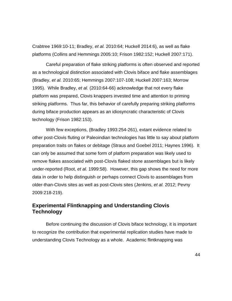
Crabtree 1969:10-11; Bradley, et al. 2010:64; Huckell 2014:6), as well as flake
platforms (Collins and Hemmings 2005:10; Frison 1982:152; Huckell 2007:171).
Careful preparation of flake striking platforms is often observed and reported
as a technological distinction associated with Clovis biface and flake assemblages
(Bradley, et al. 2010:65; Hemmings 2007:107-108; Huckell 2007:163; Morrow
1995). While Bradley, et al. (2010:64-66) acknowledge that not every flake
platform was prepared, Clovis knappers invested time and attention to priming
striking platforms. Thus far, this behavior of carefully preparing striking platforms
during biface production appears as an idiosyncratic characteristic of Clovis
technology (Frison 1982:153).
With few exceptions, (Bradley 1993:254-261), extant evidence related to
other post-Clovis fluting or Paleoindian technologies has little to say about platform
preparation traits on flakes or debitage (Straus and Goebel 2011; Haynes 1996). It
can only be assumed that some form of platform preparation was likely used to
remove flakes associated with post-Clovis flaked stone assemblages but is likely
under-reported (Root, et al. 1999:58). However, this gap shows the need for more
data in order to help distinguish or perhaps connect Clovis to assemblages from
older-than-Clovis sites as well as post-Clovis sites (Jenkins, et al. 2012; Pevny
2009:218-219).
Experimental Flintknapping and Understanding Clovis Technology
Before continuing the discussion of Clovis biface technology, it is important
to recognize the contribution that experimental replication studies have made to
understanding Clovis Technology as a whole. Academic flintknapping was

45
introduced to American archaeology during the 1950’s and 1960’s, (Jelinek 1965;
Johnson 1978; Lamdin-Whymark 2009; Swanson 1966) and provided
archaeologists with experimental options to scientifically test flintknapping
techniques (Crabtree 1966; 1967a; 1967b; Bradley and Stanford 1987) and to
explore differences in flaked stone technologies (Callahan 1979; see Clark and
Collins 2002). Moreover, flaked stone tool replication and experimentation also
generated (renewed) awareness of examining debitage associated with flaked
stone assemblages (Bradley 1975; Collins 1974; 1975:15-34; Crabtree 1972;
Wilmsen 1970; Fish 1979).
Experimental flintknapping has contributed valuable insights into Clovis
technological concepts and reduction techniques based on observations that are
unique to Clovis biface production (Hamilton 2006; Wilke 2002). While exact
methods are hypothetical, academic knappers have proven skilled at removing
channel flakes using several techniques that can successfully replicate flute scars
(Crabtree 1966; Patten 2005; 2009; Whittaker 1994:237-242).
The most reliable means of investigating flaked stone tool manufacture and
reduction patterns is through artifact refitting or conjoining analysis (Villa 1982:276-
290). In rare cases, researchers have successfully reassembled entire
manufacturing sequences (Almeida 2005). Clovis biface and blade reduction
sequences have been reassembled from discarded flaked debris (Fig.5) (Bradley
1982:204; Ferring 2001:148; Collins and Link 2003:162-173; Frison and Stanford
1982:143).

46
Figure 5– Successful refitting of a Clovis Blade core #17P1-13 from the Pavo Real Site, Texas (41BX52) (Composite photo adapted from Collins and Link 2003:162-173).
Some of the biface thinning flakes recovered at the Sheaman Clovis Site in
Wyoming (Bradley 1982:204; Frison and Bradley 1999:111; Frison and Stanford
1982:143) were reassembled. This exercise provided evidence not only of how
Clovis flintknappers serially spaced the removal of biface thinning flakes (Frison

47
1982:154), but also established the earliest claim that Clovis purposely overshot
flakes as a biface flake removal technique (Bradley 1982:203-208).
Two large Clovis overshot flakes recovered from the Gault Site were
successfully refitted during this study (Fig.6).

48
Figure 6 – Recent refitting attempts were successful of two large Clovis overshot flakes recovered from the Gault Site, Texas, 41BL323.

49
Clovis knappers adhered to most universal reduction practices to regularize
bifaces and often strived for average width-to-thickness ratios of 3:1 or width-to-
thickness ratios of 4:1 (Bradley, et al. 2010:64-65). While in general the thinness
of Clovis bifaces do vary (Bradley, et al. 2010; 84-85), Clovis knappers preferred
their bifaces to be proportional. As discussed earlier, there are technological
distinctions found in flake scars of Clovis bifaces that provide clues as to how
and/or what type of flake was removed. Flake scars such as those made by
overshot terminations or full-face flakes, are for the most part reported in Clovis
cached bifaces, but also from Clovis manufacturing sites (see above Fig. 4) (Frison
and Bradley 1999; Huckell 2014:133; Lohse, et al. 2014b:153; see also Huckell
and Kilby 2014). Occasionally, remnants of these overshot and full-face flake
scars can be visible on used/abandoned Clovis points (Fig. 7) (Bradley, et al.
2010:64-65; Smallwood 2012:689-713).

50
Figure 7— Abandoned Clovis point from the Gault Site, Texas (41BL323) with visible overshot flake or full-face scar (Spec# UT-1040-113) (Photo by M. Samuel Gardner, used with permission from the Gault School of Archaeological Research).
The exact means by which Clovis knappers held or stabilized the bifaces as
they worked or fluted them remains speculative (Bradley, et al. 2010:64).

51
However, we do know that Clovis knappers primarily used direct percussion for
production shaping and thinning of bifaces. Pressure flaking, on the other hand,
was most extensively used in reworking damaged points and tools (Bradley, et al.
2010:64, 96). As such, pressure flaking may be a technological trait that separates
Clovis technology from later (post-Clovis) fluted technologies.
In early phases of biface production, Clovis knappers would remove a few
large, well-spaced flakes (Bradley 1982:207; 2010:467; Collins, et al. 2007:103).
As the reduction continued, the flakes that were being removed guided the next
step. In order to flatten the biface, thinning flakes were removed that would have
terminated just past the midline traveling across the thickest portion of the biface
(Fig. 8). This may have been followed by another thinning flake, but this was
removed from the opposite margin and would truncate and/ or completely remove
previous termination scars. The classic Clovis biface outline would be maintained
by shaping it from the removal of short percussion flakes along the margins.
These flakes generally terminated well before the midline and helped adjust the
margins as needed throughout production (Fig. 8.1 and 8.6).
Full-face flakes (Fig. 8.5) travelled through the thickest portion of the biface
to the opposite edge without removing the opposite margin. This would thin the
biface through the reduction of mass in relation to the proportion of width loss.
Controlled overshot flakes (Fig. 8.3) not only reduced mass from the biface but a
portion of the opposite edge. In order to control the outcome of a Clovis biface,
techniques were combined to remove specific flake types throughout the reduction
process to flatten (Pers. Comm. Bradley 2014) or maintain biface shape (Collins
2007:103). Occasionally, opposed alternating diving flakes (Fig. 8.2) terminated as
a hinge, or step fracture, near the midline of the biface in order to enhance the

52
thinning process. Thinning of the biface was also accomplished by intermittent
removal of longitudinal thinning flakes from the basal edge (Fig. 8.4) throughout the
reduction process (Callahan 1979; Bradley, et al. 2010:64-65; Huckell 2007:192).
Figure 8– Schematic illustration of possible Clovis biface flaking options. (1 & 6) shaping flakes (2) opposed alternating diving flaking; (3) overshot flake (4) longitudinal thinning or channel flake; (5) full face flake; (sensu Bradley, et al. 2010:65).
Longitudinal thinning by removing a channel flake to create flute is
essentially a thinning flake (Bradley 1993:254), and is often associated with Clovis
(Fig. 9) and Folsom projectile points. However, fluting seems to be a specialized
technology that is unique to early North American point production technologies
(Stanford and Bradley 2012:29). Flute scars on Clovis points have been reported

53
to occur on one or both faces (Bradley, et al., 2010:66,89,95; Sholts, et al.
2012:3019). Fluting techniques have been well documented but these studies
mainly explored post-Clovis fluting technologies such as Folsom of North America
(see Clark and Collins 2002; Crabtree 1967a; 1967b; Crabtree 1966; Lassen 2013;
Patten 2005; 2009).

54
Figure 9 – Clovis point recovered from the Gault Site, Texas, (41BL323) exhibiting a flute or longitudinal thinning scar on the basal edge (Spec # UT 2624-1). (Photo courtesy of the Gault School of Archaeological Research)
With regard to Clovis biface technology, both end thinning and channel
flakes are essentially the same type of longitudinal thinning flake. Several
researchers have tried to clarify these differences between the two flake types.
Flakes that were removed from the basal edge of a biface during early and middle

55
phases of manufacture (Collins 1999b:17, fig.4C), are usually referred to as end
thinning flakes (Bradley, et al. 2010:66), while the removal of channel flakes is
usually removed during final and finish-out of projectile points (Morrow 1995;
Stanford and Bradley 2012:52). However, Haynes (2002:83) describes the
process of fluting as occurring in the ‘middle stage’ of Clovis biface production.
Conversely, Huckell (2007:192) states that attempting to end thin during this stage
does not constitute the specialized actions of ‘true’ fluting. With respect to the
general differences between end thinning and channel or fluting flakes, there are
no distinctions made in this dissertation as they both accomplish the same action
of removing mass through thinning.
Clovis Biface Production Flakes
As discussed earlier, Clovis biface thinning flakes often retain reduction
clues in their overall morphology – e.g. overshot terminations and large dorsal flake
scars – as well as in the striking platforms. Biface thinning flakes observed in the
Clovis archaeological record have been reported as exhibiting low dorsal flake scar
counts (Bradley 2010:470). Furthermore, the dorsal side often retain material flaws
or knapping error scars, such as hinges, that were skillfully removed by the
knapper (Bradley 2010:469; Kooyman 2000:109). According to Bradley (1982:208)
flakes that terminated as a hinge can be considered intentional if they occurred
because of opposed diving flaking (Bradley 1982:208). These same flake types
were later noted in the archaeological record at the Aubrey Clovis Site in Texas,
(41DN479) (Ferring 2001:154).
In Clovis biface technology, longitudinal thinning in the form of end thinning
flakes or channel flakes frequently retain hinged terminations. Hinge scars on the

56
dorsal side of flakes can be easily identified as being produced by longitudinal
thinning if the scar runs parallel to the lateral edges of the flake (Fig.10). This has
been observed on Clovis overshot flakes and strongly suggests they were removed
to ‘clean’ the biface of these scars (M.B. Collins, Pers. Comm. 2013).
Figure 10 – A Clovis overshot flake from Area 4 at the Gault Site, Texas, (41BL323). Arrows point to a hinge scar (right lateral edge) that was likely caused by longitudinal thinning during the middle phase of biface reduction (Spec # UT-4384-4)
While channel flakes are a distinctive flake type, the technology can be
ascribed to Clovis as well as some post-Clovis fluting cultures such as Folsom.

57
Overshot flakes are also distinctive and are considered one of the more interesting,
and informative type of flakes produced in the Clovis biface reduction repertoire.
The frequent occurrence of overshot flaking has been well documented. Overshot
flakes have been recovered, but are often observed as prominent flake scars on
bifaces, or are retained as dorsal scars on biface thinning flakes (Bradley et al.
2010:68-77; Eren, et al. 2011; Ferring 2001:151-154; Frison and Bradley 1999:31-
35, 64-67, 85-89, 90-95; Hill, et al. 2014:79-106; Huckell 2007:190-191; Huckell
2014:133-152; Huckell and Kilby 2014:1-9).
It has been accepted that Clovis intentional overshot flaking is a technique
known to occur during all phases of Clovis biface production, and the flakes vary in
size and proportions (Bradley, et al. 2010:68). However, some consider it a flaking
disaster or common mistake produced by all knappers (Bordes 1968:42; Callahan
1979; Eren, et al., 2013; 2014; Sellet 2015; Whittaker 1994:163).
Striking Platforms
Blades are defined as a type of flake that is twice as long as they are wide
(Bordes 1961; Collins 1999a:7; Bradley, et al. 2010:10-11; Williams 2014).
Although blades are not included in this study, it should be noted that complex
platform preparation traits on Clovis blades have long been considered a
conspicuous characteristic of Clovis blade manufacture (Collins 1999a:5). While
this statement is similar to what is being observed in striking platforms on biface
thinning flakes, there are few supporting data in the matter.
François Bordes and Don Crabtree (1969) both experimented with possible
techniques to remove large flakes observed in the “large, thin, precision flaked

58
bifacial implements” (Bordes and Crabtree 1969) of the Simon Cache (Butler
1963). Both were struck by the “incredibly large, rapidly expanding flakes” which
had been removed “from both faces and all margins” (Bordes and Crabtree
1969:10-11). Bordes and Crabtree (1969:11) agreed that Clovis knappers’
technique for removing such flakes must have been “unique” because the
platforms, which were very small in relation to the flake body, had to be “strong
enough to withstand the force” needed to remove them.
Based on observations of Clovis biface thinning flake platforms, they may
retain preparation traits that are easily recognized (Hall 2000). Clovis flake
platforms have often been described as having wide, straight platforms, that are
sometimes faceted, often isolated, and ground. Bradley, et al. (2010:66) defines
the platform of a “typical” Clovis thinning flake as being “ground, projected,
isolated, reduced, faceted, released, and straight” (Fig.11). Previous observations
of preparation on Clovis flake platforms has been primarily associated with channel
flakes (Morrow 1995), as well as overshot flakes where the grinding on platforms
appears as quite heavy or “frequently extending from the platform surface around
to the proximal dorsal surface” (Bradley 2010:470).

59
Figure 11 -- Illustration depicting complex platform preparation traits on a Clovis biface margin (Adapted from Bradley, et al. 2010:67).
Overshot Terminations: Flake Type or Technique?
As discussed in the previous section, one of the most fascinating flakes
identified as part of Clovis biface technology is the overshot flake. Understanding
the use of controlled overshot flaking as a technique continues to challenge
researchers. However, before discussing overshot flaking in Clovis biface
production, the use of the term “overshot” should be explored.
In terms of Clovis technology, Bradley, et al. (2010:68) describe an overshot
flake as a piece that when struck travels from “one margin across a face of a biface
(or any other form)” ultimately removing the opposite margin of the parent piece.
However, Inizan, et al., (1999) describe overshots as a “plunging” flake where the
termination arches “sharply” forward. Inizan, et al. (1999) acknowledge that
overshooting a flake can be either accidental or intentional, and moreover, their

60
existence within an archaeological assemblage reveals a great deal regarding
technical behaviors and methods applied by individual knappers (Inizan, et al.
1999:151).
Regardless of being technological, morphological, or a fatal error, the use of
the terms “overshot” and “plunging” are synonymous within the realm of fracture
mechanics, specifically the load, force, and energy that is required to create them
(Baker 2000; 2003). The key is recognizing the differences between flake
technology and flake typology. In an effort to create a suitable distinction in this
study, the term “plunging flake” (Fig. 12) will be used to describe a flake type that
dives prematurely, sometimes to a disastrous outcome (Callahan 1979; Eren, et al.
2011; Morrow 1995). The term “overshot termination” will be used, mainly in
Chapter 7 of this study, to describe a flake termination type.

61
Figure 12 – Simplified schematic showing the possible mass removal differences between a plunging flake and an overshot flake.
Plunging flakes can have catastrophic results and have been identified in
Clovis biface assemblages (Bradley, et al. 2010:72) and usually occur as end-
shock during removal of end thinning or channel flakes (Eren, et al. 2011; Morrow
1995). This can be a result of many factors such as improper platform preparation,
material inconsistencies, poor load delivery and/or low-skill; or in simple terms, if
the force load doesn’t deliver enough energy, that energy instead may rapidly
dissipate thus causing the flake to terminate prematurely. Plunging flake failure
can occur during longitudinal thinning when it dives prematurely, i.e. at the medial
section of the biface plane, removing the distal end of the biface (Fig. 13).

62
Figure 13— A discarded proximal fragment of a Clovis preform from the Gault Site, Texas (41BL323) exhibiting evidence of a catastrophic plunging flake failure caused by longitudinal thinning. The shaded area is a reconstruction of the missing distal portion. (Photo by M. Samuel Gardner, and used with permission from the Gault School of Archaeological Research)
Some morphological characteristics can help distinguish between a plunging
failure (Fig. 13) and a failed overshot flake (Fig.14). A failed overshot flake will
likely retain very specific morphologies. For example, where the lateral “shearing”
in two of a biface occurs (see also Callahan 1979:135, figure 62.4CIIbii(2)).

63
Figure 14— Drawing of a failed Clovis overshot flake that ruined a biface. Inset is probable reconstruction of original size of biface. (Drawn from Spec. No. UT-1154-15).
Some Clovis flakes have been identified as “partial cortical” overshot flakes
(Waters, et al. 2011a:83) and the terminology confuses what is technically a
plunging flake. As a Clovis reduction technique, the plunging flake was likely
employed in a controlled manner by Clovis knappers to remove cortical edges or
square edges (Bradley, et al. 2010:71; Wilke, et al. 1991:242-272) which are

64
physical properties common to Edwards chert that can be found in nodule, cobble,
or tablet forms.
This section addressed common terminological issues and discussed
differences associated with the terms “overshot flake” and “plunging flake.” While it
is a matter of perspective, the term “plunging” or “plunging flake” will refer to the
mechanical agent associated with brittle fracture of stone. With regard to the term
“overshot flake,” it is acknowledged that it is also a plunging flake (Inizan, et al.
1999), but in the field of debitage analysis, ‘overshot’ is a classification of flake
termination that differentiates it from other commonly used flake terminations like
“feathered,” or “hinged” (Brezillon 1968; Bordes 1961).
It is apparent the term “overshot flake” has become a dichotomy used to
describe a flake type as well as a controlled flaking technique with respect to Clovis
biface technology (Bradley 1982:203-207; Frison 1982:152; Bradley and Stanford
2006; Wilke, et al. 1991; Wilke 2002:247). For the purposes of this research, the
use of the terms “overshot” or “overshot flake” will be used in this manner but
distinctions will be made where appropriate.

65
Chapter 2 -- Exploring the Interpretive Potential of Clovis Waste Flakes
Most lithic analysts agree that platform bearing flakes retain clues about
knapping technologies (Andrefsky 2001:10; 2005:15-18, 91-96). Clovis technology
experts agree that Clovis knappers frequently invested effort before removing
flakes by preparing striking platforms (Bradley et al. 2010:66; Collins 1999a:66;
Huckell 2007:197; Morrow 1995) thereby exerting control over the removal of
manufacturing flakes which includes mastering control of overshot flaking (Bradley
2010:466). However, the extent of use or distribution of striking platform (platform)
preparation traits on flakes remain ambiguous and as such, expose a critical need
for basic quantitative and comparative data particularly from Clovis workshop
settings.
Observational data of the archaeological record has played a key role in
informing researchers about Clovis technology. This is particularly true regarding
platform preparation traits. Platform preparation traits are frequently reported in
Clovis biface reduction flakes and as a result, these common observations have
become assumptions (Bradley, et al. 2010:66; Bradley 1991:369-373; 2010:463-
497; Collins 1999a:46; Hall 2000; Hemmings 2007:83-137; Huckell 2007; 2014;
Morrow 1995). As such, questions exist as to whether Clovis knappers were
consistent in their application of platform preparation traits, and if platform traits
were applied uniformly across flake types. To rectify this, a model was developed
on individual flake platform details, (e.g. -- by flake phase and by flake type) of
biface manufacturing flake data from a well-documented Clovis
workshop/encampment site known as the Gault Site (41BL323) in Texas (Collins
2002). These study data reveal the extent and nature of platform preparation traits

66
and techniques observed from dense Clovis deposits produced from tool
manufacturing activities at the Gault Site. These platform preparation trait and
flake data can serve as a comparative model between other Texas Clovis sites
(Mallouf 1989; Masson 1998, Jennings 2012), as well as older-than-Clovis and
post-Clovis stone tool cultures.
Aims and Objectives
Theoretically, manufacturing debris at Clovis sites located at or near tool
stone sources, provides an ideal opportunity to examine Clovis biface
manufacturing technology (Bradley, et al. 2010:56). The data gaps associated with
Clovis biface technology forms the basis of this research.
Aims
1. Elucidate empirical and observational evidence reported on Clovis biface
manufacturing flakes and striking platforms (platforms).
2. Examine lithic assemblages from secure Clovis components at the Gault
Site for evidence of manufacturing debris related to primary biface
production activities.
3. Conduct an in-depth data collection and subsequent statistical assessment
of Clovis biface reduction flakes that focuses on individual attributes and
platform traits using acceptable standards and methods in the field of
debitage analysis.
4. Enhance our understanding of Clovis biface technology from the perspective
of manufacturing debris through comprehensive analysis of individual waste

67
flakes that can be applied to the broader acuity of Clovis biface, blade, and
flaked stone tool technologies.
Objectives
1. To identify particular issues, turning points and advancements based on
previous literature regarding the field of debitage analysis and how it relates
to and/or affected Clovis debitage studies.
2. To review all documentation concerning Clovis excavations from the Gault
site in order to identify an area with clearly defined Clovis stratum and
workshop debris.
3. To assess current database and artifact inventory records to help determine
sample size.
4. To create a coding form based on Bradley (2009:414) in order to collect and
record multiple independent variables of flake attributes and individual
platform preparation traits on Clovis biface production debris.
5. To compare and contrast these variables across flake phase and type to
determine if any patterns exist during biface manufacture.
6. To explore how the data contribute to and enhance our understanding of
Clovis technology.
Research Validation
Our understanding of platform preparation traits has been largely influenced
by expert research and first-hand experience, and as such, can be summarized as
follows in order of year published (respectively):

68
1. (Bordes and Crabtree 1969) -- François Bordes and Don Crabtree’s
(1969:10-11) experimental work included observations of the Simon Clovis
biface cache (Butler 1963) and remarked on the large flake scars describing
them as "rapidly expanding" with “small platforms.” Their comments were
the earliest published suggestions that Clovis intentionally prepared small
platforms but that they had to have been very “strong” to withstand the
energy load needed to remove such large flakes (Bordes and Crabtree
1969:10-11)
2. (Frison 1982) --Frison states, “[A]n unusual amount of platform preparation
[of a Clovis channel flake] in relation to other [Clovis] flakes” (Frison
1982:153).
3. (Bradley 1991) -- “Early stage biface thinning flakes have wide, straight
platforms that are faceted, reduced and ground (often heavily)” (Bradley
1991:373).
4. (Morrow 1995) -- "The key to Clovis biface thinning lies in specially prepared
striking platforms” … “[for] the successful removal of biface thinning flakes.
“Isolation of the striking platform focuses the [energy of the] percussion
blow…” (Morrow 1995:173).
5. (Collins 1999a) -- “[M]inimal platform preparation” was used during early
stage biface reduction, and “Platforms were produced by roughly chipping a
bevel along the edge, with platform grinding used increasingly as flaking
progressed” (Collins 1999a:46).
6. (Hall 2000) – Dennis Stanford remarks that Clovis [flake] platforms are “very
wide, very well set up and very heavily ground.” (Stanford In: Hall 2000).

69
7. (Kooyman 2000) -- “Early stage [Clovis] thinning flakes have wide, straight
platforms and are faceted and heavily ground” (Kooyman 2000:110).
8. (Ferring 2001) -- Regarding flakes recovered at the Aubrey Clovis site,
located in north Central Texas; in “Area G,” the debitage were observed as
having “finely facetted [sic] and ground platforms” (Ferring 2001:133 [Table
9.5:G-1]).
- (Collins and Hemmings 2005) -- “As flaking progressed, platforms for the
removal of large thinning flakes were sometimes isolated and more
commonly ground, resulting in bifacial thinning flakes with small, ground
platforms” (Collins and Hemmings 2005:10).
9. (Huckell 2007) –
a. With regard to knapping clusters identified as associated with bifacial
retouch Huckell states “These flake clusters are typified by thin,
expanding flakes with faceted striking platforms, often strongly lipped
and abraded” (Huckell 2007:189).
b. There were “three clusters of debitage from Murray Springs [that are]
interpreted as representing projectile point manufacture or repair ...
interestingly, almost no abraded striking platforms are observed on
any of these flakes [and] the striking platforms are only slightly
convex [and] not particularly well isolated from the surrounding
margin” (Huckell 2007:197).
10. (Bradley, et al. 2010) -- “A ‘typical’ Clovis thinning flake platform is
projected, isolated, reduced, faceted, released, straight and ground”
(Bradley, et al. 2010:66).

70
Research Hypotheses
Based on the aims and objectives of this research, two distinct hypotheses
were tested:
Hypothesis 1
Null
Clovis knappers applied, in a consistent means, a complementary suite of
platform preparation traits before striking and removing flakes during biface
manufacture.
Alternate
Clovis knappers did not consistently apply a complementary suite of
platform preparation traits before striking and removing flakes during biface
manufacture.
Hypothesis 2
Null
The observations and interpretations reported by Bordes and Crabtree
(1969:10-11), Bradley et al. (2010:66), Bradley (1991:373), Collins (1999a), Collins
and Hemmings (2005:10), Ferring (2001:133), Frison (1982:153), Huckell
(2007:189,197), Kooyman (2000:110), Morrow (1995:173), and Stanford (Hall
2000), are an accurate reflection of the nature of preparation traits commonly
observed on Clovis biface flake platforms and is supported by the data in this
study.

71
Alternate
The observations and interpretations reported by Bordes and Crabtree
(1969:10-11), Bradley et al. (2010:66), Bradley (1991:373), Collins (1999a), Collins
and Hemmings (2005:10), Ferring (2001:133), Frison (1982:153), Huckell
(2007:189,197), Kooyman (2000:110), Morrow (1995:173), and Stanford (Hall
2000) do not accurately reflect the nature of preparation traits commonly observed
on Clovis biface flake platforms.
This research is a positive step forward that will expand current knowledge
of Clovis technology by addressing specific data gap issues using both quantitative
and qualitative production flake data directly related to Clovis biface manufacture.
This research will contribute a greater understanding of the reductive processes
associated with Clovis biface flaked stone manufacturing techniques used at the
Gault Site that can be used as a comparative baseline for intra-site and inter-site
use.

72
Chapter 3 -- Debitage Analysis
Flakes or Debitage?
Stone tool production waste flakes are often referred to as debitage, a term
adapted from the French word débiter (v) meaning to dispense or discharge
(Oxford Dictionary online 2014). French prehistorians’ use of the term debitage
describes the action of being detached -- e.g. ‘preferential’ flakes (Inizan, et al.
1999:30; 65-67) -- from knappable raw materials for intentional fabrication of stone
tools (Bordes 1961:13-16; Brezillon 1968:93-99; Heinzelin de Braucourt 1962:6).
For the purposes here, the term debitage is used interchangeably with the term
flakes or flake and will be differentiated where appropriate either collectively or
individually (Shott 1994:70).
Debitage Analysis – What Flakes Can Tell Us
Every artifact has a story to tell (Fagan 2006:17) and therefore, examination
of all flaked stone tools including all associated debris is essential for properly
interpreting the archaeological record (Bordes and Crabtree 1969:1). Analysis of
flaked stone assemblages can provide evidence to help understand explain human
prehistoric stone tool cultures, how they lived, socialized, moved, exploited, and
worked local and non-local tool stone sources (Magne 2001:21).
All archaeological sites are unique; formed through site use (Whittaker and
Kaldahl 2001:49) and by waste-generating activities such as stone tool production,
tool-use and, discard (Renfrew and Bahn 1996:305). Other factors contribute to
site formation such as post-depositional actions like trampling (Odell 2003:67-69)

73
and cumulative effects of organic litter, formation, and deflation of soils, and faunal-
turbation (Wood and Johnson 1978).
However, despite a site’s uniqueness, most prehistoric archaeological sites
are composed of similar artifacts such as stone tools and any associated flaked
stone debris (Bradley 1975:5). The debris often makes up the vast majority of
flaked stone tool assemblages (Andrefsky 2005:1; Odell 2003:118). Unless
otherwise disturbed, flakes struck from a core usually remain where they fell
(Almeida 2005; Brezillon 1968:93; Henry et al., 1976:61). Flakes en masse are
usually stable in that they are reliably copious (Boldurian and Cotter 1999:37; Odell
2003:120), and are generally repulsive to relic hunters (Shott 1994:71).
In analytical lithic hierarchies, the sluggish rise of the “lowly” flake (Baker
2006) resulted from the recognition by some lithic technologists of behavioral
information that flakes and debitage preserve (Crabtree 1972:1). It is known that
flakes produced by bifacial or core reduction activities often exhibit traits that
provide clues that can be associated with specific flaked stone tool industries
(Frison 1982:153-54).
Theoretically, an individual flake can retain more diagnostic clues than flake
scars on stone tools themselves (Crabtree, 1972:1; 1975:106, Odell, 2003:88). For
example, some of the oldest stone tools of Middle Palaeolithic Neanderthals
(Mortillet 1869:172) employed a technique of core reduction known as Levallois
technology (Bordes 1968:30). Levallois technology has been extensively
documented and has been defined as an “industry of flakes” (Sonneville-Bordes
1961:77; Fish 1979:32). Some Mousterian age sites indicate the presence of
flake-production to make tools using specially shaped Levallois cores to facilitate
74
the removal of distinctive, thick, flakes (Eren and Lycett 2012; Whittaker 1994:30-
32) that were then modified into tools (Bordes 1961:2, 13, 71-72).
Debitage analysis is defined as the systematic study of waste and debris
produced from flaked stone tool manufacture, use, and maintenance. Michael J.
Shott (1994; 2004) provides a fine historical synthesis on analytical approaches to
flakes and debitage. Analysis of debitage can be accomplished through a number
of methods using sorting, measuring, counting, weighing, and may include
qualitative and quantitative data (Boisvert 1985:1-103). Debitage, especially flakes
in large quantities, affords analysts a surplus of raw data that makes it an ideal
sampling medium for statistical analyses (Boldurian and Cotter 1999:37).
With the surge of academic experimental flintknapping during the 1950s and
1960s, (Andrefsky 2005:4; Jelinek 1965), some sporadic developments have
positively affected the progress and advancement of debitage analysis. The
development of theoretical and philosophical perspectives (Crabtree 1966; 1967a;
1967b; 1972) fell upon a few archaeologists who recognized that all flaked stone
artifacts and debris were fundamentally linked to understanding the archaeological
record (Bordes 1961; Bordes and Crabtree 1969; Bradley 1972; 1975:5-13;
Crabtree 1972; 1975; Collins 1974; 1975:15-34; Fish 1979; 1981; Wilmsen 1970).
By the mid-1970s and into the 1980s experimental flintknapping was firmly
ensconced in the field of lithic analysis (Andrefsky 2005:8; Jelinek, et al. 1971;
Johnson 1978). Experimental flintknapping provided lithic analysts a viable means
to address problems in the archaeological record (Jelinek, et al., 1971; Outram
2008). However, with few exceptions, (Henry, et al. 1976; Patterson and
Sollberger 1978) methods and approaches for examination of and management of

75
vast amounts of debitage saw no tangible standard industry practices being tested
or developed during this time.
Eventually this problem reached a crisis point. In 1985, Alan P. Sullivan and
Kenneth C. Rozen (1985) wrote and published an article that threw debitage
analysis into the pitch of analytical debate (Andrefsky 2001:1). Their American
Antiquity article was a critical turning point for debitage analysis. By proposing a
new method, now known as the Sullivan and Rozen Technique, or SRT, Sullivan
and Rozen (1985) were attempting to address serious problems with standards of
practice for analyzing debitage (Shott 1994:78). Put simply, the SRT method was
a form of individual flake analysis that provided an objective approach to flake
classification, but unfortunately, no theoretical basis was discussed for the
application of this typology (Ahler 1989:87).
The SRT method was met with criticism and an unequivocal backlash,
(Amick and Mauldin 1989a; Prentiss and Romanski 1989). In spite of the reproach
for the SRT, it brought about much needed attention to the field by compelling lithic
analysts to rethink all practices and principles (Andrefsky, 2001:2-3) associated
with debitage analysis (Andrefsky 2001; 2005; Amick and Mauldin, 1989b;
Bradbury and Carr 1995; Hall and Larson 2004; Ingbar, et al. 1989; Odell 2003;
Henry and Odell 1989).
As a subfield of lithic analysis, any examination of by-products generated
from flaked stone tool manufacture comprises the basis of debitage analysis. A
general standardization of terminology and flake types (Andrefsky 2005:86) have
developed through time (Andrefsky 2001; 2005; Crabtree 1972; Inizan, et al. 1999;
Marois, et al., 1997; Shott 1994), as have reliable techniques of measurement
(Andrefsky 2005:100-01; Inizan, et al. 1999:107).

76
Along with the proposed SRT, a variety of methods have been tried and
tested providing options for lithic analysts to choose or combine, to deal with
individual specimens or entire populations (Ahler 1989; Andrefsky 2005:113; Henry
and Odell 1989).
Vast amounts of debitage in the archaeological record can be an
overwhelming nuisance (Whittaker and Kaldahl 2001:32-60). Lithic analysts on
some level might assume fleeting empathy for those scholarly predecessors who
rarely noticed ‘flake chips’, or recorded them as rubbish (Stevens 1870:104, 511),
ignored them altogether, or worse, tossed them away (Wilmsen and Roberts
1978:16).
There is no “best” method or approach to deal with debitage. Nevertheless,
there are options to deal with particularly large amounts of debitage such as mass
analysis or “aggregate analysis.” Aggregate analysis is used to sort through vast
amounts of debitage using a graduated series of screens (Henry, et al. 1976). The
most positive aspect of aggregate analysis is the reduction of time spent sorting,
examining, and weighing artifacts (Odell 2003:130).
On the other hand, if issues exist such as mixing of knapping activities
within the archaeological record (Andrefsky 2007:392-402), technological or other
trait data may be overlooked if using only aggregate analysis (Andrefsky 2007;
Odell 2003:131-32). As such, aggregate analysis may fall short, unless there is
allowance for initial organization of flakes and debitage such as sorting by
technological contexts, traits or by tool maintenance activities (Andrefsky
2005:140). Some approaches may be more suitable than others (Andrefsky
2001:13), contingent on a number of factors such as time, money, or research
objectives (Ahler 1989:85-118). However, combining aggregate (or mass) analysis

77
with individual flake analysis -- (Andrefsky 2005:142; Bradbury and Carr 2004) is
likely the best holistic approach to analyzing debitage (Odell 2003).
Other subtleties can also be inferred from analyzing debitage in the
archaeological record which provide insight into toolstone economy, stone tool
technology, tool use, and maintenance (Collins 1998c; 1998b; Ferring 2001:124;
Huckell 2007:170; Hemmings 2007:83). In addition, manufacturing behaviors and
unusual knapping techniques can be inferred via the presence of flaked stone
debris, including stone tool production failures (Aubry, et al. 2008). Reassembling
of flake reduction sequences (Almeida 2005:41-42) can also provide clues into
individual or group skill levels of knappers (Frison 1982; Lohse 2010:161;
Whittaker and Kaldahl 2001:32).
Despite the tremendous progress made during the past three to four
decades, analyzing debitage is no less a tedious endeavor (Whittaker and Kaldahl
2001:33), but an endeavor well worth the effort. Recording individual flake
variables from hundreds of biface thinning flakes is time consuming, but the data is
worth collecting. While individual flake analysis is considered useful, it is rarely
undertaken. Instead, the standard practice remains either graduated sieves or
counts, weights or cluster analysis. However, none of these would expose a Clovis
technology manufacturing process.

78
Chapter 4 -- The Gault Site
The Gault Site is located in Central Texas in the southwestern portion of Bell
County, near the small town of Florence, approximately forty miles north of the
state Capital of Austin, Texas (Fig.15). The Gault site is a multicomponent site and
has a well-documented record of prehistoric stone tool cultures known in the
Central Texas region initially ranging from Clovis to Late Prehistoric (Fig. 16) and
more recently, the discovery of even older cultural materials below the Clovis
horizon (Collins, et al. 2013:521-539).
Excavations at the Gault site have occurred intermittently since 1991 until
April of 2013 when Area 15 excavations were concluded. The course of
investigations has revealed information regarding the geoarchaeological integrity of
the Gault site and as such, the understanding of the geologic formations and
hydrologic activities of Texas informs our interpretations of why early Texans were
drawn to this Central Texas region.

79
Figure 15 -- The location of the Gault Site (41BL323) relative to the Texas State Capital of
Austin, U.S.

80
Figure 16 – Basic chronology of Central Texas Archaeology (sensu Collins 2004:101-126.
Geology of Texas and the Gault Site
Physiographic Setting
The Edwards Plateau (Fig. 17) is a prominent limestone feature in Central
Texas, and forms part of the Southern High Plains periphery (Collins 2007:74).

81
Figure 17— Edwards Plateau region relative to the Southern High Plains (Color overlay of Great Plains is modified from Trimble 1980. Used with permission from the U.S. Geological Survey, Dept. of the Interior U.S.G.S., U.S. Geological Survey).
The Edwards Plateau is one of the most abundant sources for high quality
chert in North America (Banks 1990:59). The plateau forms the eastern upland
boundary that abuts the rolling Gulf coastal plains (aka Texas Blackland Prairie)
that spread south and east into the Gulf of Mexico. These adjoining landscapes
form a transitional line known as the Balcones Ecotone (Fig. 18) and attracted
prehistoric people for millennia for its wide range of floral and faunal resources as
well as other amenities in the form of limestone rock shelters, quality raw toolstone,
rivers and artesian springs (Collins 2002; 2004:103; 2007:74).

82
Figure 18—Edwards Plateau and Coastal Plains (sensu Collins 2002)
Regional Geology and the Texas Landscape
The Jurassic period in North America saw dramatic geologic events that
included the formation of the Cordilleran Mountain belt along the Pacific west
margin of North America (Fig. 19). Tectonic shifting, (continental colliding, and
rifting) triggered mountain building events along the Pacific margins (Stoffer 2003).
These geologic events created a basin in the middle of the North American
continent. Around 115 million years ago during the Early Cretaceous, the basin
flooded with seawater from both northern and southern inlets of the North

83
American continent (Fig. 19) forming an inland water feature known as the Western
Interior Seaway (WIS) (Rice and Shurr 1983; Stoffer 2003). At its peak, some 80
million years ago, this inland ocean stretched from the Arctic Ocean all the way to
the Gulf of Mexico and covered most of, or perhaps the entire area that is now
Texas (Cobban and McKinney 2013; Ferring 2007; Rice and Shurr 1983).
Figure 19— Composite illustration showing the Cordilleran and Ouachita Orogenic belts and their relevance to the Western Interior Seaway shown at its most extensive point. These events respectively helped formed the geology of the Great Plains, as well as the Central Texas Region of the Edwards Plateau (The extent of the WIS is based sensu amplo on Cobban and McKinney, 2013, U.S. Geological Survey, Dept. of the Interior/USGS)
The depositional remnants of the WIS are still visible in the modern
landscape of Central Texas. Limestone features formed under the warm shallow
waters of the WIS from layers of thick marine carbonate and chalk sediments that
were laid down during marine transgressive episodes (Ferring 2007).

84
Regression/transgression episodes also caused massive amounts of water to
down cut into the eastern edges of the Edwards Plateau transporting sediments
that were deposited to the east forming the Coastal Plains (Ferring 2007).
A topographic limestone feature known as the Balcones Escarpment
formed along a fault zone that separates the Edwards Plateau from the Gulf
Coastal Plains (Woodruff and Abbott 1979; 1986). The fault zone -- known as the
Balcones Fault Zone -- tracks along the same axes of the buried Ouachita orogenic
belt (Fig. 19 & 20) that formed during the Late Paleozoic (Budnik 1986; Ferring
2007).
The juxtaposition of the Balcones Escarpment, which follows along the
buried axes of the ancient Ouachita Mountains, (Fig. 20) forms part of the Edwards
Plateau water regeneration zone that recharges the Edwards Aquifer. For
instance, as rainwater sieves through the karstic Edwards limestone it eventually
contacts with impermeable Comanche Peak limestone, where water is forced out
as artesian springs along drainage areas from the edges of the plateau (Swanson
1995:23-28; Woodruff and Abbott 1986).

85
This discussion summarizes the major geologic events in Texas that
continues to have, a significant influence over economic and cultural behaviors of
its human inhabitants from prehistoric to modern times. The enduring effects of
these dramatic events created long-lasting viable environments with a wide range
of raw resources that include water as well as silicified chert as prehistoric
toolstone, to modern petroleum products (Swanson 1995:29; Woodruff and Wilding
2007).
Figure 20– Illustration showing the formative association between the Edwards Plateau, the Balcones Escarpment, and the Balcones Fault Zone, which trend along the buried Ouachita-Marathon mountain belt axes and its relevance to the Gault Site (sensu Collins 2002).

86
Local Geology and Soils
The Gault site is situated near the spring-fed headwaters of Buttermilk
Creek (Boyd 2010:181-194) where incised limestone outcrops contact undulating
valley fill of colluvial toe slopes, alluvial, and floodplain deposits. Erosional events
through millennia transported sediments that filled the valley. Minor tributaries cut
down from the plateau in the upper (south) valley and drain into Buttermilk Creek
during heavy rains (Fig. 22).
Buttermilk Creek flows near limestone outcrops that form part of the Lower
Cretaceous formation of the Fredericksburg Group (Proctor, et al. 1974; Collins
2002). These rock formations are comprised of karstic and dolomitic Edwards
Limestone atop impervious limestone clays (Fig. 21). The thin rocky soils and xeric
uplands of the Edwards Plateau are host to live oaks, prickly pear cacti, and ashe
juniper (Collins 2002). The floodplain valley of Buttermilk Creek was filled with clay
and rock sediments of colluvium, and alluvium that were eroded over time from soft
limestone and chalks in the Plateau’s uplands (Ferring 2007; Swanson 1995:27-
28).

87
Figure 21– Basic schematic of the bedrock geology at the Gault Site. (Graphic used with permission from the Gault School of Archaeological Research. Illustration by D. Clark Wernecke).
The modern soils of the Buttermilk Creek valley are comprised of the
Lewisville Series of deep clayey soils that form on stream terraces and limestone
toe slopes (Huckabee 1977). Buttermilk Creek is a first-order stream and tributary
of Salado Creek that forms part of a regional watershed basin of the Brazos River
(Tyler 1936). The modern history of the valley in and around the Buttermilk Creek
valley records its use as being primarily for livestock grazing (Gilpin and Longley
1995:396).
The surrounding edges of the Buttermilk Creek floodplain are lined with
larger trees of oak (including burr oak) pecan, black walnut, and hackberry. A
small population of bois d’arc trees (Maclura pomifera), -- aka Horse Apple or

88
‘Bodark’ – are currently found along the outer edges of the floodplain valley as well
as some upland areas, whose dense wood properties were highly favored by
prehistoric peoples for crafting bows and other tools (Collins 2002).
The local geology at the Gault Site (see Figs. 21 & 22) is vital for supplying
fresh water to the area, and likely provided in a similar means for prehistoric
peoples who lived there.
Figure 22– Topographic illustration of the Gault Site and excavation areas since 1991. (Map graphic used with permission from the Gault School of Archaeological Research).
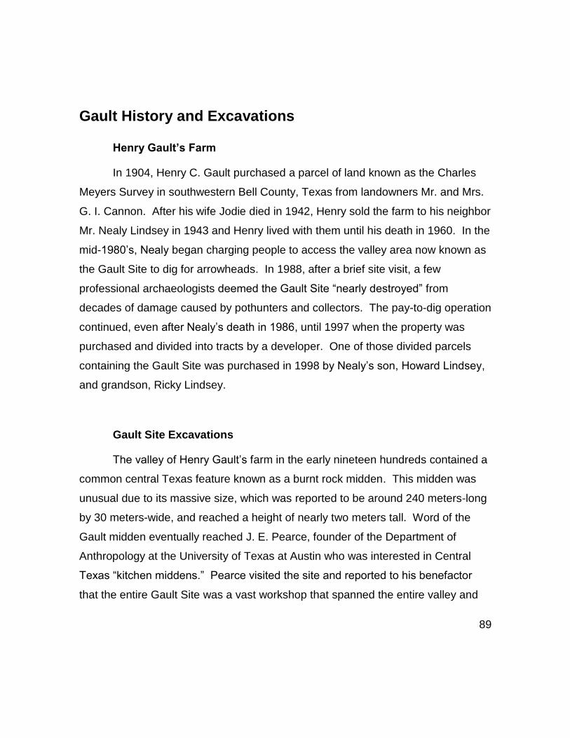
89
Gault History and Excavations
Henry Gault’s Farm
In 1904, Henry C. Gault purchased a parcel of land known as the Charles
Meyers Survey in southwestern Bell County, Texas from landowners Mr. and Mrs.
G. I. Cannon. After his wife Jodie died in 1942, Henry sold the farm to his neighbor
Mr. Nealy Lindsey in 1943 and Henry lived with them until his death in 1960. In the
mid-1980’s, Nealy began charging people to access the valley area now known as
the Gault Site to dig for arrowheads. In 1988, after a brief site visit, a few
professional archaeologists deemed the Gault Site “nearly destroyed” from
decades of damage caused by pothunters and collectors. The pay-to-dig operation
continued, even after Nealy’s death in 1986, until 1997 when the property was
purchased and divided into tracts by a developer. One of those divided parcels
containing the Gault Site was purchased in 1998 by Nealy’s son, Howard Lindsey,
and grandson, Ricky Lindsey.
Gault Site Excavations
The valley of Henry Gault’s farm in the early nineteen hundreds contained a
common central Texas feature known as a burnt rock midden. This midden was
unusual due to its massive size, which was reported to be around 240 meters-long
by 30 meters-wide, and reached a height of nearly two meters tall. Word of the
Gault midden eventually reached J. E. Pearce, founder of the Department of
Anthropology at the University of Texas at Austin who was interested in Central
Texas “kitchen middens.” Pearce visited the site and reported to his benefactor
that the entire Gault Site was a vast workshop that spanned the entire valley and

90
“over this whole field are such quantities of flint chips, broken artifacts, and human
refuse generally as I have ever seen at any other place” (Pearce 1930).
Pearce was granted permission by Henry to send workers to cut a trench
into the large midden. By the fall of 1929, a three-man crew headed by H. B.
Ramsaur trenched the large midden in the valley (Fig. 23). However, by
November, after eight weeks, the crew was routed by bad weather, and the
excavation was abandoned.

91
Figure 23-- H. B Ramsaur (left) and crew (top & bottom right) trenching into the Gault Site middens (circa 1929). (Photos J.E. Pearce Manuscript Collection, used with permission from the Texas Archaeological Research Laboratory, Univ. of Texas at Austin and the GSAR).

92
In 1988, prominent Texas archaeologists who were familiar with the site’s
pay-to-dig history, visited with Elmer Lindsey, a relative who continued Nealy’s
pay-to-dig operations at Gault. Pat Mercado-Allinger of the Texas Historical
Commission and Dr. Thomas Hester with Texas Archeological Research Lab
(TARL- Univ. of Texas at Austin) and others, were interested in interviewing Elmer
and surveying Gault as a possible site for an upcoming field school, but
negotiations with Elmer failed to come to an agreement. Hester later wrote up the
visit and described the site as completely devastated due to years of pay-to-dig
looting (T. Hester, Pers. Comm. 2013). While the damage is incalculable, most of
the damage to site was contained to the midden and subsurface finds of Archaic
“arrowheads” which were more profitable to collectors.
A collector named David Olmstead paid to dig at the Gault Site sometime
during the 1980’s. Olmstead reportedly dug below the disturbed midden and
uncovered a heavily resharpened Alibates Clovis point ‘sandwiched’ between two
ornately incised limestone pebbles (Fig. 24). Peter Bostrom, of the Lithic Casting
Lab in Troy, Illinois, contacted Dr. Thomas Hester (TARL) regarding Olmstead’s
unusual finds. Hester subsequently contacted Olmstead and arranged for he and
TARL colleague Dr. Michael B. Collins, a renowned Clovis expert, to photograph
the artifacts. Olmstead was asked to co-author a paper with Hester and Collins on
the unusual engraved artifacts (see Collins, et al. 1991).
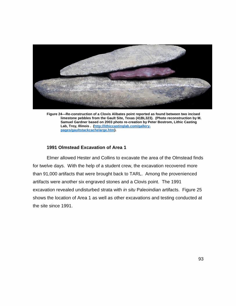
93
Figure 24—Re-construction of a Clovis Alibates point reported as found between two incised limestone pebbles from the Gault Site, Texas (41BL323). (Photo reconstruction by M. Samuel Gardner based on 2003 photo re-creation by Peter Bostrom, Lithic Casting Lab, Troy, Illinois . (http://lithiccastinglab.com/gallery-pages/gaultstackcachelarge.htm).
1991 Olmstead Excavation of Area 1
Elmer allowed Hester and Collins to excavate the area of the Olmstead finds
for twelve days. With the help of a student crew, the excavation recovered more
than 91,000 artifacts that were brought back to TARL. Among the provenienced
artifacts were another six engraved stones and a Clovis point. The 1991
excavation revealed undisturbed strata with in situ Paleoindian artifacts. Figure 25
shows the location of Area 1 as well as other excavations and testing conducted at
the site since 1991.

94
Figure 25 – Block designations for excavations at the Gault Site from 1991 through 2002 and their locality within the Buttermilk Creek Valley. (Mapping by Ken Brown, Eddie De La Rosa, and Marc Beherec. Graphic provided courtesy of the Gault School of Archaeological Research)
1998 Salvage Excavation (Areas 7 and 8)
Although Howard and Ricky Lindsey halted all pay-to-dig operations, they
were themselves avid collectors of ‘arrowheads.’ In 1998 while using heavy

95
equipment to dig along the western upper valley of the site, Howard Lindsey
uncovered the remains of a large animal. Dr. Collins was contacted to examine the
remains, which turned out to be the mandible of juvenile mammoth (M. columbi).
This discovery led to a salvage operation being permitted by the Lindseys. During
the salvage, several Clovis points as well as flake tools and blade artifacts were
found associated with the proboscidea remains.
1999-2002 Excavation Highlights (Areas 2-14)
After the successful salvage in 1998, the presence of Clovis-age artifacts
associated with the mandible provided further evidence to support the 1991
findings that the deeply buried Paleoindian deposits at Gault were relatively
untouched by pothunters. This encouraged Dr. Collins to negotiate a three-year
arrangement with the Lindseys who agreed to allow unfettered access, testing, and
excavation around the site.
At the end of the three-year investigation in May of 2002 an additional
500,000 artifacts, 300k being from Clovis deposits, had been recovered from
fourteen excavations and test areas from less than three percent of the entire
estimated site. These investigations also established that the entire Texas
Prehistoric chronological record (see previous Fig. 16) was represented at the
Gault Site which reveals a nearly continuous occupation by humans extending over
13,000 calendar years (Collins 2002; 2007:59-80).
After the three-year investigation was concluded, Dr. Collins remained in
close contact with the Lindseys who came to understand the scientific value of the
Gault Site. After careful negotiations, the Lindseys agreed to sell the property in
2006. Attempts to acquire funding from donors and interested parties were

96
unsuccessful. However, knowing this would likely be the only chance to help the
Gault Site get the protection it needed, Dr. Collins purchased the site using
personal funds and immediately donated it to the Archaeological Conservancy, a
U.S. nonprofit that protects archaeological sites nationwide.
The excavations in Area 8 extended investigations of the 1998 M.columbi
salvage. Area 8 was an important excavation in terms of understanding the site
history and the complex geology that preserved the Gault Site. Area 8 has also
been the subject of numerous graduate research projects as well as a publication
on Clovis technology (Waters, et al., 2011a).
2007-2013 Excavation of Area 15
Based on evidence from several test excavation areas where cultural
materials have been found below the known Clovis horizon at the site, a grant from
the National Science Foundation was awarded to the Gault School of
Archaeological Research, a Texas non-profit organization that manages the Gault
Site. The grant was specifically earmarked to fund the excavations in Area 15,
which started in 2007. With the help of thousands of volunteers, comprised of
Gault staffers, academics, professional colleagues, and students, the excavations
were eventually completed when bedrock was reached in June of 2013. Area 15
excavations exposed intact Archaic components not destroyed by looting, as well
as Late to Early Paleoindian deposits. Area 15 also recovered evidence of cultural
materials, approximately 15 to 20-centimeters, below the Clovis horizon, not yet
classified.
Recently, Optically Stimulated Luminescence (OSL) dates for the Gault Site
include the latest OSL samples collected during the 2007-2013 excavations. The

97
Gault Clovis dates are currently estimated between 13,400 to 12,900 Cal BP
(Collins, et al. [forthcoming]).
Gault Geomorphology
Since E. B. Howard introduced the concept in the 1930s, multidisciplinary
approaches have been vital for archaeological investigations and the geosciences
are an essential part of Paleoindian studies (Holliday 1997:1-20). Geomorphology
is a geologic based science that has gained the interest of North American
archaeologists. Geomorphology in essence “bridges” the gap between
archaeological science and earth sciences (Goldberg, et al. 2001:vii).
Geomorphological processes—e.g. alluvial systems, formation of soils, and
sedimentation -- directly affect the integrity of archaeological sites (Goldberg and
MacPhail 2006). Knowledge of how various systems shape and modify past
landscapes helps archaeologists to understand depositional issues in the
archaeological record (Goldberg, et al. 2001: vii-xi).
Brandy Gibson in 1997 conducted a geoarchaeological site potential study
of the Buttermilk Creek valley for a master’s thesis (Gibson 1997). Gibson was not
able to collect data directly associated with the Gault Site due to restricted access
by the landowner at the time. She was able to construct a proxy model of the
Buttermilk Creek valley based on her identification of six alluvial units. These units
included her findings of a “Brown Paleosol” that contained a chronometric series of
Late Paleo to Early Archaic diagnostic projectile points (Gibson 1997:46, 51).
Gibson’s research provided data that helped with later geomorphic studies at the
Gault Site.

98
Research was conducted by Heidi Luchsinger (2002) for a master’s thesis at
the Gault Site. The study focused on the stratigraphic integrity of Area 8, which
was excavated into the floodplain deposits in the southwest (upper) Buttermilk
Creek valley of the site. Luchsinger’s study analyzed micromorphological data and
included stratigraphic profiles of not only the excavated floodplain facies, but an
adjacent channel facies as well. Luchsinger’s floodplain profile drawings identify
development of the Royalty Paleosol (Nordt 1992) that formed along an alluvial
deposit atop what appeared to be a Clovis-age surface area that Luchsinger
identified as a “Clovis Soil” (Luchsinger 2002:17, 31).
Dawn Alexander (2008) conducted a study for her master’s thesis that
investigated post-depositional disturbances within Area 8 as well (Alexander 2008).
Her analysis of data revealed the good stratigraphic context of the artifacts in the
Clovis component and concluded that disturbance of Clovis artifacts within Area 8
were primarily due to cultural activities and not natural processes.
Anastasia Gilmer (2013) conducted a magnetic susceptibility study for her
master’s thesis in Area 15 (Gilmer 2013). Gilmer (2013:122) found no evidence of
artifact movement in Area 15 by natural processes nor evidence of high-energy
scouring known to occur in the Buttermilk Creek valley and surrounding areas
(Gibson 1997; Nordt 1992) stating that distinctive stratigraphic deposits contained
the Clovis component and the older-than-Clovis component, respectively. These
studies by Gibson (1997), Luchsinger (2002), Alexander (2008), and Gilmer (2013)
contributed valuable data regarding the state of the Buttermilk Creek valley area
that indicated high preservation of Paleoindian deposits in the Gault Site.
This body of knowledge and research has enabled Gault researchers to
understand the Paleoindian occupation of the site as well as the favorable

99
environments that have preserved the archaeology. The WIS inland Cretaceous
ocean left behind a rich plateau environment with one of the largest chert deposits
in North America (Banks 1990:59) and a continual water supply within the
limestone. This coupled with the flora and fauna of both the uplands and lowlands
made the Gault Site an attractive and sustainable location.

100
Chapter 5 – Area 4 Excavations (Study Area)
As discussed previously, Clovis knappers were known for actively procuring
high quality stone materials, and therefore, would have been drawn to the
abundant quality of chert found at the Gault Site. The archaeological record at
Gault reveals Clovis knappers heavily exploited the chert resources during frequent
or long-term occupations of the site. The excavations in the locality known as Area
4 were conducted specifically for documenting the well-preserved stratigraphic
record of the Clovis component (Pertulla 2004:34). Based on this as well as
interviews of the principal investigators and detailed assessment of the existing
excavation records, Area 4 is the focus for this research study.
Area 4 is located roughly 70 meters to the southwest of Area 8. During the
1999-2002 field seasons, test units around Gault penetrated through the heavily
looted midden that measured up to 60-centimeters in depth in places, and
consistently turned up modern rubbish, such as discarded beer and soda cans,
plastic wrappers from cigarette packs and candy, abandoned tools, etc. The
disturbed layer was usually removed as one level or stripped off before excavation
began.
Area 4 (Fig. 26) is located in an alluvial fan in the upper valley just
southwest of the modern stream of Buttermilk Creek. Based on field records, the
arbitrary datum was set at an elevation of 100m -- located at N1000 E1000 – and
the starting elevation of Area 4 was around 97.50 meters. The grid area of Area 4
included seventy-three (n=73) one-by-one meter squares (Fig. 27). Once the
disturbed midden layers were removed, all levels were excavated in one-by-one
meter squares, initially dug in 10-centimeter increments until contact was made
with the Royalty Paleosol (Luchsinger 2002; Nordt 1992), when the levels were

101
excavated in five-centimeter levels that penetrated into Clovis and reached below
Clovis stratum.
Figure 26 – Contour map of the Gault Site, Texas (41BL323) showing the location of Area 4 within an alluvial fan. (Map used with permission from the Gault School of Archaeological Research)

102
Figure 27—Area 4 Basic Excavation Grid
The highest elevation recorded for a diagnostic Clovis artifact in Area 4 was
around 96.91m and the lowest elevation of a Clovis diagnostic was recorded at
96.51m. The highest concentrations of Clovis flakes and debitage occur between
the elevations of 96.88m and 96.61m. The total depth of the Clovis stratum in Area
4 is approximately thirty-five to forty centimeters and gently undulates across the
excavation area (Fig.28).

103
Figure 28– Stratigraphic representation depicting general elevation of Clovis stratum in Area 4. (Graphic Modified used with permission from the GSAR).
By the time Area 4 was completed in 2002, the number of artifacts
cataloged from the Clovis component in Area 4 was estimated to be around 16,000
artifacts. As of this research, the Area 4 Clovis flaked stone tool and faunal
assemblage is approximately 125,328, with ninety-percent being flakes, and
related debris. Since Area 4 is only meters away from outcrops of high quality
Edwards chert, the vast amount of Clovis manufacturing debris supports the

104
inference that Area 4 excavated into a Clovis workshop setting. Amongst the tools
recovered from the Clovis stratum in Area 4 were at least thirteen broken, heavily
re-worked, or exhausted/discarded Clovis projectiles. This number is
proportionally low when compared to the amount of manufacturing debris.
Although recent geochemical analysis of Edwards Plateau chert and Clovis points
from the Gault Site indicated that Clovis points were carried some distance from
the original source and discarded only when broken (Speer 2014). This provides a
likely explanation as to why the number of Clovis points is relatively low.
The Clovis manufacturing debris revealed abundant biface production flakes
as well as unremarkable flaking debris and/or cortical flakes likely produced from
shaping-out of lenticular nodules or other tabular forms of Edwards variety chert.
Other distinctive artifacts usually associated with Clovis biface production were
identified from the Clovis stratum in Area 4 included end thinning flakes, channel
flakes, and overshot flakes.
Furthermore, the Clovis flake and tool assemblage included indicative debris
associated with blade production including discarded or failed blades and blade
cores (Bradley, et al. 2010:10; Collins and Link 2003:157-182), blade core
preparation flakes (Bradley, et al. 2010:19; Ferring 2001:146), and platform
rejuvenation flakes as well as corner blades (Williams 2014). The large amount of
manufacturing debris not only provides an ideal opportunity to study flaking
technology produced in a Clovis workshop setting (Bradley, et al. 2010:56), but
theoretically is the ideal situation for analytical sampling (Shott 1994).

105
Chapter 6 -- Methodology
Individual flake analysis, (IFA) was chosen as the most beneficial approach
for this study in order to collect a robust amount of data in the form of technological
values that are often indicators of stone tool cultures (Andrefsky 2005:114).
Approaches used for observation, recording and measuring techniques were
based on well-known theoretical principles of debitage and lithic analysis defined
by Andrefsky (2001:6-13; 2005:91-142), Bradley (1975:5-13; 2009:265) Collins
(1974:160-178; 1975:15-34), Crabtree (1972; 1975:105-114), Odell (2004:121-130)
and Inizan, et al., (1999:33).
As discussed in Chapter 5, examination of Area 4 field records including
profiles, diagrams and plan drawings were helpful in assessing the location and
elevation of Clovis stratum in each unit. Three-hundred and twelve (312) five-
centimeter levels had been identified as containing Clovis-bearing deposits in Area
4. Each Clovis level-per-unit had 300 to 400-pieces of flakes/debris/debitage on
average per five-centimeter level. The highest concentrations of flakes, debitage,
and debris occur between the elevations of ~96.88m and ~96.61m. However,
further analysis would be necessary in order to confirm this, such as GIS
computation and 3D analysis, but is beyond the scope of this research.
Before sampling, excavation field notes, level record forms, inventory, and
inventory databases were thoroughly examined to determine temporal and spatial
clarity of Clovis levels in Area 4 in particular where diagnostic Clovis tools had
been confidently identified.
Finally, as a student of aboriginal flintknapping, personal knapping
experience provided and continues to provide a greater understanding of how and

106
why some flakes are made, and how flakes create stone tools. As Pellegrin
(2004:57) states, “one can only recognize what one already knows”.
Sampling Methods
The benchmark for this study included recording of both broken and whole
flakes with observable striking platforms. Broken flakes, which included step
flakes, were limited to proximal fragments that retained observable striking
platforms. All flakes were measured linearly and the minimum size was set at ten
millimeters (10 mm) with no maximum limits on either whole or broken flakes.
The Gault database and inventory records show that 130,707 flaked stone
artifacts and faunal items were recovered from Area 4. Of these, 124,478 pieces
(Table 1) were identified as either general debitage, flakes (piece plotted, etc.) or
angular debris.
The amount of flakes and debitage (Table 2) recovered from Area 4
excavations equaled 114,406 pieces. Approximately 74,048 of these were flakes
sorted from 1/4” inch screens with the remaining 40,358 (35%) being sorted from
1/8” inch screened materials. All bulk flake and debitage materials included
indeterminate angular pieces such as chert fragments and flake shatter.

107
Table 1 -- Clovis Flakes Debitage and Debris from Area 4
Table 2 -- Clovis General Debitage from Area 4
Description of Sorted Clovis bulk flakes and debitage
n %
1/4" inch* 74048 (65%)
1/8" inch** 40358 (35%)
Total 114406 (100%)
* contains flakes larger than >10mm ** contains flakes or debris smaller than <10mm
The flake sample and analytical data sets were chosen from materials that
were clearly identified from excavated units containing diagnostic artifacts
associated with Clovis technology (Bradley, et al. 2010:64; Collins 1999a; Jenkins,
et al. 2012; Waters, et al. 2011a), such as Clovis bifaces, preforms, projectile
points, overshot flakes, channel flakes, and blades and blade production debris.
Based on the area and Clovis parameters discussed above, as well as
information gathered from artifact inventory records, field notes, profiles, and
paperwork generated during the excavation Area 4, a flake population of ~23,939
flakes and debitage were extracted for sampling. This population consisted of bulk
flakes, as well as 599 piece-plotted flakes, (see Table 1 and 2), from fifty, well-
AREA 4 CLOVIS FLAKES, DEBITAGE, DEBRIS
Description n Percentage (%)*
General Debitage 114406 88%
Flakes (point prov.) 3243 2.0
Angular chert 6829 5.0
TOTAL 124478 95%
* Of Area 4 Assemblage (n=130707)

108
defined Clovis bearing lots in Area 4. These lots represent thirty-seven (37) of the
seventy-three (73) one-by-one meter square (1x1 m2) units excavated in Area 4.
These flakes were systematically examined and sorted based on sampling
benchmarks allowing whole or broken flakes, but retained observable striking
platforms, and were at least 10 mm and larger. The final data set of (n=) 2185
flakes were recorded and analyzed for this study.
Of note, blades or blade fragments were not considered for this study and
any reference to blades has strived to be unambiguous. Flake study parameters
did not include any flaked debris identified as angular debris or shatter. Likewise,
any flakes where striking platforms were heavily obscured by the precipitation of
calcium carbonate (CaCO3) (Durand, et al. 2010) were excluded.
Finally, unless otherwise stated, the debitage and flakes recovered from
Area 4 assemblage are primarily made from local Edwards variety chert.
Data Collection
The aim of this study is to collect platform preparation data primarily from
Clovis biface manufacturing flakes in order to assess the technology of biface
production. The final data set of 2185 flakes was sorted using flake criteria stated
above. The data set includes flakes associated with Clovis biface manufacturing
activities and other stone tool production flakes associated with blade production,
as well as, general or indeterminate flakes. The following is the recording criteria
for this flake study, and meets or exceeds acceptable standards of practice for
macroscopic examination of flakes and debitage (Andrefsky 2001; 2005). A copy
of the flake and data collection form is located in Appendix 1 and is adapted from

109
Bradley 2009:265, 414 for Clovis biface technology. A more in-depth glossary and
definition of terms based on this form is located in Appendix 3.
Measuring Striking Platforms
The body of this study focuses on flake striking platform and platform
preparation traits. Platforms were measured in millimeters using digital calipers,
(Andrefsky 2005:95, 101) to record length (L) and depth (D) (Fig. 29) of individual
platforms.
Figure 29-- Measuring striking platform depth (left) and striking platform length (right)

110
Striking Platform Preparation Traits
Platform attributes as well as complex platform preparation traits were
broken down into three subcategories -- platform status, platform shape (Fig.30)
and platform preparation (Fig. 31). Individual preparation traits were recorded as
present or absent, except for lipping and grinding, which were broken down further
to quantify the degree of their presence/use and are presented in Table 3.
Table 3 -- Platform Attributes and Preparation Traits Recorded
Grinding was recorded as ‘present’ along the edge, obverse, or reverse of
the platform. Grinding on a platform-bearing flake can be detected by observation
and/or feel. The use of a magnifying glass, visor, or microscope between 10X and
Platform Status
Remnant (partial)
Shat/Crushed
Lipped
Plain
Cortical
Platform Shape
Straight
Concave
Convex
Dihedral
Platform Preparation
Grinding edge
Grinding obverse
Grinding reverse
Faceted
Reduced
Released
Isolated

111
20X magnification also helped determine the presence and extent of grinding on
some of the 10-15mm size flakes. With regard to lipping, a coding system was
used to identify the degree of lipping or prominence that a platform retained (Table
4).
Figure 30 – Simple schematic of basic platform shapes

112
Table 4 – Coding used for Platform Lipping
Figure 31 illustrates the platform preparation traits identified above (see
Table 3). Grinding was divided into three categories (‘edge/margin’ –
‘dorsal/obverse’ and ‘ventral/reverse’). Faceting reduces the platform on the
ventral/strike-side of platform. The platform may exhibit two or more flake scars
that can be parallel, radiate or transect previous flake scars. Reducing removes
material overhangs or weak spots but from the dorsal (obverse) side of the
platform and may exhibit two or more flakes scars (Fig. 31) that can be parallel to
the striking-axis. Releasing a platform is intended to weaken the area around the
platform by removing small flakes that often create small or truncated scars on the
ventral/reverse (strike-side) of the flake. An isolated platform can mean flakes
were removed from the dorsal/obverse side of the striking platform prior to removal
and the platform appears prominent and separated.
Lipping
Code
Description of Code
Qualifiers
L (normal Lipping Lipping is present and visually detectable
ML Minor Lipping Detectable by “feel”
H/E Heavy/Extreme Lipping
Lipping is heavy (prominent) or extreme lipping e.g. “Edge-Bite” or “Edge-Collapse” (Collins 1974:160-175)
O No lipping Lipping not detected visually or by feel; bulb is usually prominent

113
Figure 31 –Diagram of platform preparation traits on a biface margin prior to the outlined area of flake is removed. Grinding is represented in dark gray (adapted and modified from Bradley, et al. 2010:67).

114
Plain and cortical platforms were coded as shown in Table 5.
Table 5 – Coding for recording plain and cortical platforms
Measuring Flake Dimensions
Flake length (L), width (W), and thickness (Th) (Figures 32 and 33) were
measured in millimeters using digital calipers. These measurements were taken of
the morphological length of the flake.
Figure 32– Profile drawing of a flake arrow indicates measurement of thickest area of the flake body.
Plain or Cortical Code
Platform Status Trait Description
P =Plain No preparation detected
C =Cortical The striking platform retains the original surface, or subcortex of the parent material.

115
Figure 33–Basic flake descriptions of the dorsal and ventral view of a Clovis biface thinning flake from Area 4. The red arrows represent measurements taken of the flake body at its widest and longest points.
Flakes were recorded as being complete (whole) or incomplete (proximal
end). Termination types were recorded as feathered, overshot, hinged, or
broken/step (Table 6 and Figure 34).

116
Table 6 – Flake condition and status
Flake Status Complete
Incomplete
Flake Termination
Feathered
Overshot
Hinged
Broken / Step
Flake Phase
Early
Middle
Late
Flake Type
Biface Shaping
Biface Thinning
End Thinning/Channel
Other
Indeterminate

117
Figure 34-- Flake formation and terminations (sensu Cotterell and Kamminga 1987).

118
Analytical Phases of Clovis Biface Reduction
The value of establishing reduction sequences to flaked stone tools is a
dated concept (Holmes 1894:136) that was modernized by Don Crabtree (1972).
The theory has since been refined by Bradley, et al. (2010:77), Bradley and Giria
(1996), Callahan (1979), Morrow (1995), and Sanders (1990). With regard to
biface manufacture, it is a process that can occur in stages (Andrefsky 2005:31;
Callahan 1979:18), or as a continuum, (Bradley, et al. 2010:77), and has been
debated on several fronts (Bradley, et al. 2010:78-79; Bradbury 1998; Bradbury
and Carr 1999; 2014:20-38; Huckell 2014:137; Miller and Smallwood 2012; Shott
1996; 2007).
Clovis biface production is assumed to follow a logical order of reduction
based on primary, secondary or finishing (Huckell 2007:193). Following Bradley, et
al. (2010:78), the term ‘stage’ will denote production discontinuities and ‘phase’ will
refer to the reduction continuum using multiple flaking actions. All flakes in this
data set were assigned progression values based on Clovis biface technology
(Bradley, et al. 2010:77-79), and were recorded as early, early/middle, middle,
middle/late, or late.
Assignation of a flake to a phase and flake type was determined using as
many clues from the flake to classify it (Andrefsky 2005:124). This included, but
was not limited to, the overall complexity of the striking platform, the number of
dorsal flake scars, the overall size and shape, as well as thinness or thickness,
and, amount of cortex the flake retained. For example, if a flake retains more than
fifty-percent of the original cortical rind, it is commonly associated with early
reduction stages. However, other clues should be considered before making a

119
determination. Finally, any flake in the sample that could not be confidently
determined as a type or placed within a phase was recorded as ‘other or
‘indeterminate.’
Qualifying Analytical Biface Flake Types
Four separate biface flake types were identified on specific flake traits
discussed early as well as what each flake accomplished – e.g. shaping or
thinning, or longitudinal thinning. Any flakes that were ambiguous, were coded
either ‘indeterminate’ or ‘other’ if they could be ascribed to a different activity such
as blade manufacturing.
With regard to biface shaping flakes (BFS), Inizan, et al. (1999), broadly
define these as a series of flakes that are removed to create a particular outline of
a biface, but normally do not travel through the thickest portion of the biface
(Inizan, et al. 1999:39-40). Root, et al. (1999) suggest biface outlines are shaped
by removing short flakes along the edge of the biface (Root, et al. 1999:15). BFS
flakes in this study were identified as being bifacial if they retained three or more
dorsal scars and the flake body is often wider than long. However, the overall
morphology, size, or thickness of shaping flakes can vary. Finally, BFS flakes may
or may not have a prepared striking platform.
With regard to biface thinning flakes (BFT), these are usually identified as
flakes with three or more dorsal scars (Huckell 2007:171). Platform preparation
traits vary (Bradley, et al. 2010:66). Dorsal flake scars can be situated in a crossed
pattern, overlap, or be opposed or multidirectional. BFT flakes can vary in size,
thickness, and ventral curvature – e.g. straight or curved. End thinning/channel
flakes (ET/Ch) were identified by their morphology recognized as multiple flake

120
scars that overlap in a perpendicular manner to the striking axis of the flake (Fig.
35).
Figure 35 – Flake scar characteristics of a Clovis end thinning or channel flake
A fourth flake type, biface shaping/thinning flakes (BfST) were added to
include those flakes that exhibited traits characteristic of both biface thinning and
biface shaping flakes and are analyzed .
All data was hand-recorded onto a coding form adapted from Bradley
(2009:414). See Appendix 1 for flake and data collection form and Appendix 3 for
breakdown of the terminology relevant to data collection form.
Statistical Methods
Statistical analysis was conducted by looking at platform and flake traits by
both flake phase and flake type. Analysis looked at counts and percentages of
each trait and compared them across flake phase and flake type to assess if any

121
discernable patterns were present. This was tested using Pearson’s chi-squared
analysis. The test was used to discern if there was a statistically significant
difference in the data. This is tested using the following null (Ho) and alternate (Ha)
hypotheses:
Ho: The distribution of the data across each group is not statistically different
Ha: The distribution of the data across each group is statistically different.
The Chi-square test calculates a p-value, and the null hypothesis is
rejected at <0.05. If the results indicated a statistically significant difference,
standardized residuals were used to assess where this difference was derived.
The calculation for this is as follows:
𝑧 = [𝑜𝑏𝑠𝑒𝑟𝑣𝑒𝑑 − 𝑒𝑥𝑝𝑒𝑐𝑡𝑒𝑑] − 0.5
√𝑒𝑥𝑝𝑒𝑐𝑡𝑒𝑑
Standardized residuals were calculated for each cell and values greater
than ± 2 were discussed.
For the analysis of flake and platform metrics, the mean and standard
deviations were calculated and compared as well as range, and the maximum and
minimum sizes. For an analysis of flake type, several statistical tests were used to
determine any significant differences. In order to conduct these tests the
distribution of the data was first tested for normality. This was conducted using the
Shapiro-Wilk test that assessed the statistical significance of the distribution. This
test used the following null and alternate hypotheses:
Ho: The population is normally distributed.
Ha: The population is not normally distributed.

122
The null hypothesis is rejected if the p-value is less-than 0.05.
Normality testing was important as subsequent testing depended on whether or not
the data were normally or non-normally distributed. As the data were non-normally
distributed, the Kruskal-Wallis non-parametric significance test was used. In
essence, this test determines if two or more populations were statistically
significantly different using the following hypotheses:
Hₒ: The populations from which the data sets have been drawn have the
same mean.
Hₐ: At least one population has a mean larger or smaller than at least one
other population.
In essence, the null hypothesis indicates no statistically significant
differences whereas the alternate hypothesis indicates statistically significant
differences. Furthermore, the null hypothesis is rejected if the ρ-value is < 0.05.
Following the Kruskal-Wallis Test, the Tukey-Kramer HSD (Urdan 2010) test
was used as a method for identifying the statistical significance on populations of
three or more. Tukey-Kramer HSD compares each population in the analysis and
provides a ρ-value for each group-to-group comparison. If the ρ-value is < 0.05
then the difference between those two specific groups is statistically significant.
Any statistically significant result presented was further analyzed to determine
where the significance was derived.
With regard to the five platform preparation traits that are the focus of the
analysis, – ground, faceted, reduced, released, and isolated – (Bradley, et al.
2010:66), platforms were assigned a score based on how many preparation traits
were present. In this respect, a score of “1” equates to one preparation trait
present, while a score of “5” indicates all five traits were present. This was then

123
used as a proxy for complexity: Wherein the number of traits used likely denotes
the extent of attention given, essentially knapping behaviors, during biface
reduction and/or flake production.
Prior to the complexity analysis, correlation of the five platform preparation
traits were explored using non-parametric correlation tests using Spearman’s P
and Hoeffding’s D analytical tests and are presented in Chapter 7.
With regard to small cell values, chi-square analysis cannot be conducted
so Fisher’s Exact Test was used instead.
All raw data were entered into Microsoft Access ® and then imported to
Excel ® spreadsheets for analysis. Statistical analysis was conducted using SAS
Institute Inc. JMP ® Pro 11.0.0.

124
Chapter 7 -- Clovis Flake Study Results and Analysis
The first section of the analyses presents basic distribution and metrics of all
flakes and flake types in the 2185 flake data set. The flake data are broken down
by flake type and reduction phase and are presented in Table 7 and Table 8. Six
hundred seventy-five flakes represent a fifth category of flake assigned as “other”
which represents 30.89% of the 2185 data set. “Other” flakes are those not
associated with biface manufacturing, such as flakes that were deemed
ambiguous, or associated with other knapping activities like blade manufacture
(e.g. blade core tablet flake Ferring 2001:146).
To sum up, the aim of this research is to understand the technology of
Clovis biface reduction from the perspective of Clovis manufacturing, explicitly
biface flakes, and platform preparation traits. From the original data set of 2185
flakes, 1510 (69.12%) were confidently identified as flake by-products of Clovis
biface manufacturing and are the primary focus for most sections of analyses.
Finally, unless otherwise stated, most statistical analyses conducted will
analyzed the data using two comparative groupings of flake type and flake phase.
Descriptive Statistics of All Flakes
Twenty one hundred eighty-five (2185) flakes were recorded in the original
data set that was recovered from in-situ well-stratified Clovis deposits from Area 4
of the Gault Site. Out of these, nearly seventy-one percent (70.94%) were
complete flakes while the remaining 29.06% percent were incomplete or broken
flakes.

125
Overall biface thinning flakes (BFT) occurred in the highest number,
followed by biface shaping flakes (BFS) and biface shaping/thinning flakes (BfST).
Forty flakes were identified as end thinning/channel flakes (ET/Ch), (Table 7).
Table 7 – Percentages/Counts of Data Set by Flake Type (n= 2185)
Flake Type
Count (n) Percent (%)
Biface Shaping (BFS) 392 17.94
Biface Shaping/Thinning (BfST) 184 8.42
Biface Thinning (BFT) 894 40.92
End Thinning/Channel (ET/Ch) 40 1.83
Other 675 30.89
TOTAL 2185 100
Table 8 shows the counts and percentages of these same flakes by phase.
The middle phase contained the highest number of flakes (n=684, 31.30%)
followed by the late to finish phase with 483 (22.11%) flakes. The early phase
(n=303, 13.87%), early to middle phase (n=274, 12.54%), and middle to late phase
(n=361, 16.52%) all have similar numbers of recorded flakes. Finally, 80 (3.66%)
flakes were not assigned to any phase due to the ambiguous nature of those
flakes.

126
Table 8—Percentages/Counts of Data Set by Flake Phase (n=2185)
Flake Phase Count (n) Percent (%)
Early 303 13.87
Early/Middle 274 12.54
Middle 684 31.30
Middle/Late 361 16.52
Late/Finish 483 22.11
Indeterminate 80 3.66
Total 2185 100
A descriptive analysis of platform preparation traits on all 2185 flakes was
undertaken and presented in Table 9. Seventy-five (3.43%) flakes exhibited
unprepared or ‘plain’ platforms. This indicates that, in the majority of cases, some
form of platform preparation was conducted prior to flake removal. According to
Bradley, et al. (2010:66), Clovis biface thinning flakes often exhibit specific
preparation traits that are ground, faceted, reduced, released, and isolated and
were recorded individually.
It is important to note that these platform preparation traits were not
mutually exclusive; therefore, they can occur as a single preparation or in
combinations with other platform preparation traits. Thus, the percentages
reported in Table 9 do not equal 100%.
Platform reduction was the most common recorded preparation trait with
1407 (64.39%) flakes exhibiting this form of preparation. This was followed by
platform isolation (n=1324, 60.59%) and ground platforms (n=1283, 58.72%).
Faceting was recorded in only 954 (43.66%) flakes while released platforms were
recorded in 498 (22.79%) flakes.

127
Table 9 -- Descriptive Analysis of Platform Preparation Traits of All Flakes (n=2185)
Platform Preparation Traits
*Count (n=) *Percent (%)
Faceted 954 43.66
Reduced 1407 64.39
Released 498 22.79
Isolated 1324 60.59
Ground 1283 58.72 *Due to number of variables, counts and percentages will not equal 100/100%
This analysis indicated that while 96.57% of platforms were prepared, no
single trait was used on every flake detachment. An analysis of the number of
different combinations used on all platforms indicated that 28 different
combinations of those traits listed above in Table 9 were used. The most frequent
combination was the use of all five traits with 265 examples. However, this only
represents 12.13% of the entire sample. This highlights the fact that Clovis
platform preparation was a complex technique with no single unified method
utilized.
The next section examines the metric dimensions using refined flake and
platform data sets. Over fifteen-hundred flakes in the original data set were
identified as being produced during biface manufacture.

128
Analysis of Clovis Biface Flakes -- Refining the Data Set
As discussed in the Methodology (Chapter 6), all observational data and
metric data were collected separately. During data collection, observational data
were used to ascertain flake phases and flake types. On the other hand, metric
data were collected, not only as standard practice associated with individual
debitage analysis, but also to be used as a benchmark, or control per se, to gauge
the subjectivity of biface flakes being placed within a reduction phase.
Based on the premise of this research, the next section of analyses and
results examined a refined dataset of 1510 flakes (69.12% of 2185) identified as
produced or associated with biface manufacture. The following analyses start with
presenting results of the general attributes of biface flakes as well as basic platform
attributes, again, related to biface manufacture.
Biface Flake Metrics
One thousand eighty-two (1082) or 71.65% of the 1510 data set were whole
flakes and the remaining 428 or 28.34% were incomplete or broken. The following
section analyzed whole flakes only.
The mean length, width, and thickness of the biface flake data are reported
in Table 10 along with the maximum, minimum, and ranges of flake lengths,
widths, and thicknesses. These data were then analyzed using two specific
analytical groups of biface phase (Table 11 and Figure 36) and biface flake type
(Table 12 and Figure 37).

129
Table 10 – Biface Flake Metrics of Whole Flakes -- Length/Width/Thickness (n=1082)
The mean dimensions of flakes by phase are presented below in Table 11
and Figure 35.
Table 11-- Biface Flake Metrics of Whole Flakes (L/W/Th) by Phase
Early Early/Middle Middle Middle/Late Late
Length
Mean 54.03 41.99 35.46 25.88 17.16
Std Dev 28.26 19.84 18.27 14.30 9.31
Std Err 2.56 1.80 1.05 1.03 0.50
Width
Mean 47.93 36.53 30.59 22.05 14.63
Std Dev 23.01 15.26 15.03 11.14 7.16
Std Err 2.08 1.39 0.87 0.80 0.39
Thickness
Mean 10.45 7.42 5.50 3.69 2.30
Std Dev 4.66 3.03 3.27 2.04 1.68
Std Err 0.42 0.28 0.19 0.15 0.09
Length Width Thickness
Mean 30.74 26.60 4.93
Standard Deviation 20.84 17.39 3.84
Standard Error 0.63 0.53 0.12
Range 149 134.3 24.4
Minimum 4.2 3.9 0.6
Maximum 153.2 138.2 25

130
Figure 36 – Biface Flake Mean Dimensions of Whole Flakes L/W/Th by Phase.
Analyses of the overall flake averages are presented by flake type in Table
12 and Figure 37. These indicate that BFS flakes are wider and shorter than the
three remaining flake-type categories, BFT flakes, BfST, and ET/Ch flakes, with
ET/Ch being on average the longest flake type.
Table 12 – Biface Flake Metrics of Whole Flakes (L/W/Th) by Flake Type
FLAKE TYPE
Shaping
Shaping & Thinning
Thinning
End Thinning/Channel
Length
Mean 19.81 29.43 36.28 42.15
Std Dev 13.93 19.55 21.74 22.05
Std Err 0.79 1.62 0.90 3.90
Width
Mean 22.11 27.70 28.57 29.34
Std Dev 13.60 18.45 18.68 13.14
Std Err 0.77 1.53 0.77 2.32
Thickness
Mean 4.37 5.51 5.04 5.82
Std Dev 3.96 4.28 3.63 3.81
Std Err 0.22 0.35 0.15 0.67
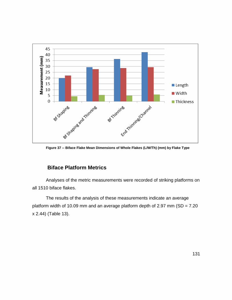
131
Figure 37 -- Biface Flake Mean Dimensions of Whole Flakes (L/W/Th) (mm) by Flake Type
Biface Platform Metrics
Analyses of the metric measurements were recorded of striking platforms on
all 1510 biface flakes.
The results of the analysis of these measurements indicate an average
platform width of 10.09 mm and an average platform depth of 2.97 mm (SD = 7.20
x 2.44) (Table 13).

132
Table 13 — All Platform Metrics (W/D) (n=1383)
Width (mm) Depth (mm)
Mean 10.09 2.97
Standard Deviation 7.20 2.44
Standard Error 0.19 0.07
Range 53.20 22.81
Minimum 1.30 0.09
Maximum 54.50 22.9
Table 14 and Figure 38 breaks the platform dimensions down into phase
and Table 15 and Figure 39 by type.
Table 14 – Platform Metrics (mm) by Phase (n=1383)
Early Early/Middle Middle Middle/Late Late
Pf Width
Mean 18.05 14.40 10.69 8.37 6.59
Std Dev 11.21 8.27 6.20 4.61 3.73
Std Err .96 0.68 0.31 0.27 0.18
Pf Depth
Mean 6.05 4.45 3.12 2.36 1.73
Std Dev 3.86 2.56 2.02 1.64 1.10
Std Err 0.33 0.21 0.10 0.10 0.05

133
Figure 38 – Platform Metrics (mm) by Phase (n=1383)
Table 15 – Platform Metrics (mm) by Flake Type (n=1383)
Shaping Shaping and Thinning
Thinning End Thinning/ Channel
Pf Width
Mean 11.77 11.22 9.06 10.57
Std Dev 8.60 7.96 6.11 6.32
Std Err 0.45 0.61 0.22 1.04
Pf Depth
Mean 3.12 3.20 2.83 3.56
Std Dev 2.99 2.46 2.14 2.11
Std Err 0.16 0.19 0.08 0.35

134
Figure 39— Platform Metrics Platform Mean Dimensions (W/D) by flake type (n-1383)
These biface flake and platform metric data together indicate that as biface
reduction progressed, the overall dimensions of the flakes and flake platforms also
decreased by phase (see Patterson 1982 and Patterson 1990).
The above results of biface flake and platform metric data by phase and
type provide a basic accounting of the data set. Based on the value of the means,
it is noted that the standard deviations are high. However, this is expected due to
the variability of the refined biface data set. As such, to help characterize the
degree of variability, further analysis was conducted and the results are presented
using a box-and-whisker plot along with a “scatter” diagram of the platform
dimensions by phase (Figure 40), and flake dimensions by phase (Figure 41). The
results support a steady decrease of the overall dimensions of flakes and platforms
within their respective ranges of variability.

135
Figure 40 – Box Plot Platform Dimensions (W/D) by Phase (n=1383)

136
Figure 41– Box Plot Whole Flake Dimensions (L/W/Th) by Phase

137
Further analysis of overall platform metrics by type indicated that platforms
were longer than deep. This result can be seen in the depth-to-width ratios in
Table 16, which indicate that BFS flakes have the largest depth-to-width ratio of
1:3.77, followed by BfST with 1:3.51, with BFT at 1:3.20 and ET/Ch having the
lowest at 1:2.97. This is seen in table 13 earlier, which indicates in all cases that
70% or more of the overall platform size is derived from the width.
Table 16-- Platform Depth to Width Ratios by Flake Type (n=1383)
Platform by
Type
Pf Width Pf Depth D:W ratio
w+d w/w+d d/w+d
BFS 11.77 3.12 3.77 14.89 0.79 0.21
BfST 11.22 3.20 3.51 14.42 0.78 0.22
BFT 9.06 2.83 3.20 11.89 0.76 0.24
ET/Ch 10.57 3.56 2.97 14.13 0.75 0.25
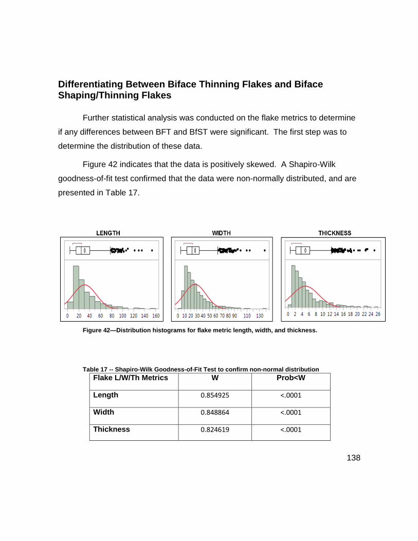
138
Differentiating Between Biface Thinning Flakes and Biface Shaping/Thinning Flakes
Further statistical analysis was conducted on the flake metrics to determine
if any differences between BFT and BfST were significant. The first step was to
determine the distribution of these data.
Figure 42 indicates that the data is positively skewed. A Shapiro-Wilk
goodness-of-fit test confirmed that the data were non-normally distributed, and are
presented in Table 17.
Figure 42—Distribution histograms for flake metric length, width, and thickness.
Table 17 -- Shapiro-Wilk Goodness-of-Fit Test to confirm non-normal distribution
Flake L/W/Th Metrics W Prob<W
Length 0.854925 <.0001
Width 0.848864 <.0001
Thickness 0.824619 <.0001

139
Because these data have non-normal distributions, (see above, Fig. 42 and
Table 17) non-parametric tests were used to assess statistical significance.
Kruskal-Wallis is a non-parametric significance test (Urdan 2010) and was used in
the first phase of the analysis. The results of the Kruskal-Wallis test (Table 18)
shows in all cases that the null hypothesis must be rejected and the alternate
hypothesis accepted. While the results of this test indicate that for each metric at
least one population has a mean that is significantly different from one other
population, it does not reveal any specific group.
Table 18 -- Kruskal-Wallis test
Flake Metrics
Chi-Square
df
Prob>Chi-Sq
Length 218.9085 3 <.0001
Width 36.4696 3 <.0001
Thickness 35.1407 3 <.0001
Following the Kruskal-Wallis Test (Table 18), the Tukey-Kramer HSD
(Urdan 2010) test was used. Analysis of length (Table 19) and width (Table 20)
shows the results of the Tukey-Kramer HSD test on the metrics by flake type. This
test indicated there was a statistically significant difference between the lengths of
each flake type except ET/Ch flakes and BFT flakes. In terms of flake width, the
analysis indicated there are statistically significant differences between BFT flakes
and BFS flakes as well as statistically significant differences between BfST flakes
and BFS flakes.

140
Table 19 -- Tukey-Kramer HSD Analysis of Flake Length
Flake Groups Compared
Type by Type
Difference Std Err Dif Lower CL Upper CL p-Value
ET/Ch BFS 22.334 3.617 13.026 31.641 <.0001
BFT BFS 16.463 1.362 12.958 19.968 <.0001
ET/Ch BfST 12.714 3.805 2.924 22.504 0.005
BfST BFS 9.620 1.953 4.595 14.644 <.0001
BFT BfST 6.844 1.802 2.206 11.481 0.001
ET/Ch BFT 5.870 3.538 -3.234 14.975 0.346
Table 20 -- Tukey-Kramer HSD Analysis of Flake Width
Flake Groups Compared Type by Type
Difference Std Err Dif Lower CL Upper CL p-Value
Channel BFS 7.232 3.187 -0.970 15.433 0.106
BFT BFS 6.460 1.200 3.372 9.548 <.0001
BfST BFS 5.591 1.721 1.163 10.018 0.007
Channel BfST 1.641 3.353 -6.986 10.268 0.961
BFT BfST 0.869 1.588 -3.217 4.955 0.947
Channel BFT 0.772 3.118 -7.251 8.794 0.995
The significant differences in those flakes designated, as BfST flakes can be
further explored using a technique outlined by Collins (1999). The first step is to
compare the width-to-length (w:l) ratios of each flake type. Table 21 lists these
ratios and demonstrates that ET/Ch has the highest w:l ratio at 1:1.44. This is
followed by BFT flakes w:l 1:1.27 with BFS flakes having the lowest w:l ratio of
1:0.90. The second step in this analysis was to calculate the ratio of length, width,
and thickness. The first step of this calculation is to sum the length, width, and
thickness measurements then divide each metric by this value (outlined in Table
21). This gives an indication of how much of the total shape of a flake is derived

141
from each measurement. This analysis indicates that BFT flakes derive fifty-two
percent (52%) of their size from length, forty-one percent (41%) from the width, and
just seven percent (7%) from thickness.
BFS flakes are opposite of this pattern in terms of length and width wherein
BFS flakes derive forty-three percent (43%) of their size from length and forty-eight
percent (48%) derived from the width.
Table 21 -- Size and Dimension Analysis by Flake Types
Metric by
Flake Type
Length Width Thickness w:l ratio
l+w+t l/(l+w+t) w/(l+w+t) t/(l+w+t)
BFS 19.81 22.11 4.37 0.90 46.30 0.43 0.48 0.09
BfST 29.43 27.70 5.51 1.06 62.65 0.47 0.44 0.09
BFT 36.28 28.57 5.04 1.27 69.88 0.52 0.41 0.07
ET/Ch 42.15 29.34 5.82 1.44 77.31 0.55 0.38 0.08
This analysis can also be graphically depicted to highlight these differences.
Figure 43 articulates the mean length and width of each bifacial flake type. This is
depicted by superimposing square outlines to represent each flake type. This
illustrates the differences in length and width between not only BFT flakes, BFS
flakes but BfST flakes as well. These differences can be further expressed, again
using the calculations in Table 21, by taking the calculations of size (ratio) of length
and width (l:w) the magnitude differences are removed from the samples providing
a better expression of size whereby the specific differences between BFT, BfST
and BFS flakes become more tangible (Figure 44). By removing the magnitude
differences, for comparative purposes, it becomes apparent that BFT remove less
mass but is the most invasive flake type, whereas BFS remove mass from the

142
edge but are less invasive. However, the BfST flakes fall between both BFS and
BFS flakes; in essence, bridging the gap between the previous two flake types by
removing mass from the edge they are more invasive than BFS flakes.
While these data presented are based on subjective typologies, the findings
highlight an important part of the Clovis reduction continuum. Clovis knappers
would remove different types of flakes depending on what was necessary during
phase of reduction and that knappers would seek to alter the length of flake
removals depending on these necessities.
Figure 43 – Comparison of flake lengths and widths articulated as squares to represent size of flake types -- biface shaping (BFS), biface thinning (BFT), and biface thinning/shaping (BfST).

143
Figure 44 -- Comparison of expressions of flake size ratios with magnitude removed
While these data presented are based on subjective biface flake typologies,
the findings highlight an important part of the Clovis reduction continuum. Clovis
knappers would remove different types of flakes depending on what was necessary
during phases of reduction by altering the length of flake removals needed.
Analysis of Flake Type Frequencies by Phase
As discussed, analyses were conducted only on those flakes produced
during of biface production. Out of the original dataset consisting of 2185 flakes
recorded, 1510 flakes were found to be related to specific aspects of biface
manufacture. Table 22 summarizes these data and provides a breakdown of the
different flake types by phase.
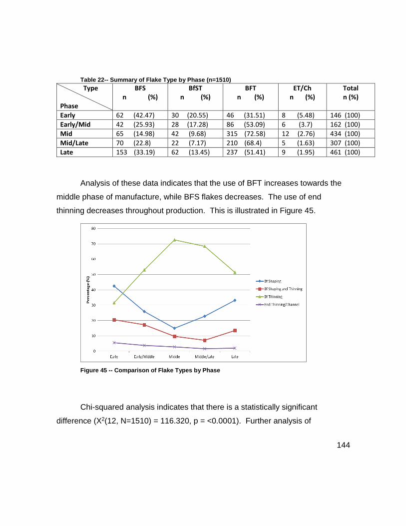
144
Table 22-- Summary of Flake Type by Phase (n=1510)
Type Phase
BFS n (%)
BfST n (%)
BFT n (%)
ET/Ch n (%)
Total n (%)
Early 62 (42.47) 30 (20.55) 46 (31.51) 8 (5.48) 146 (100)
Early/Mid 42 (25.93) 28 (17.28) 86 (53.09) 6 (3.7) 162 (100)
Mid 65 (14.98) 42 (9.68) 315 (72.58) 12 (2.76) 434 (100)
Mid/Late 70 (22.8) 22 (7.17) 210 (68.4) 5 (1.63) 307 (100)
Late 153 (33.19) 62 (13.45) 237 (51.41) 9 (1.95) 461 (100)
Analysis of these data indicates that the use of BFT increases towards the
middle phase of manufacture, while BFS flakes decreases. The use of end
thinning decreases throughout production. This is illustrated in Figure 45.
Figure 45 -- Comparison of Flake Types by Phase
Chi-squared analysis indicates that there is a statistically significant
difference (X2(12, N=1510) = 116.320, p = <0.0001). Further analysis of

145
standardized residuals of the chi-squared tests reveals that the significance is
largely derived from the differences in percentages of BFS flakes and BFT flakes in
the early phase and middle phase.
Analysis of Flake Terminations
Termination by Phase
Analysis of flake termination by phase is presented in Table 23. The results
indicated that feather terminations were the most common across all phases.
Table 23 -- Termination by Phase (n=1510)
Termination Phase
Overshot
n (%)
Hinged
n (%) Step/Broken
n (%) Feathered
n (%) Total
n (%)
Early 25 (17.12) 25 (17.12) 13 (8.9) 83 (56.85) 146(100)
Early/Middle 3 (1.85) 25 (15.43) 38 (23.46) 96 (59.26) 162(100)
Middle 33 (7.6) 67 (15.44) 125 (28.8) 209 (48.16) 434(100)
Middle/Late 6 (1.95) 38 (12.38) 111 (36.16) 152 (49.51) 307(100)
Late 7 (1.52) 29 (6.29) 113 (24.51) 312 (67.68) 461(100)
Figure 46 (below) further illustrates this and demonstrates a negative trend
in both hinged and overshot terminations towards the latter phases of production.
Chi-squared analysis indicates that there is a statistically significant difference
(X2(12, N=1510) = 139.93, p = <0.0001). Analysis of the standardized residuals
indicated that this difference was derived from the higher numbers of overshot
flakes occurring in the early and middle phases while the numbers of hinged flakes
were lower than expected in the late phase. Flakes with a broken/step termination
were lower than expected in the early phase and higher than expected in the

146
middle/late phase. While feathered terminations were lower than expected in the
middle phase and higher than expected in the late phase.
Figure 46 -- Terminations by Phase
This analysis was conducted a second time with step/broken flakes
removed (Table 24) as it is difficult to assess if the step occurred during
manufacture or later. This is illustrated in Figure 47.

147
Table 24 -- Termination by phase – w/ step/broken flakes removed
Termination Phase
Overshot
n (%) Hinged
n (%) Feathered
n (%) Total
n (%)
Early 25 (18.8) 25 (18.8) 83 (62.41) 133 (100)
Early/Middle 3 (2.42) 25 (20.16) 96 (77.42) 124 (100) Middle 33 (10.68) 67 (21.68) 209 (67.64) 309 (100)
Middle/Late 6 (3.06) 38 (19.39) 152 (77.55) 196 (100)
Late 7 (2.01) 29 (8.33) 312 (89.66) 348 (100)
Figure 47 -- Terminations by Phase (w/ step/broken flakes removed)
This analysis demonstrates more clearly the decrease in numbers of
overshot flakes towards the latter phases, conversely the number of feathered
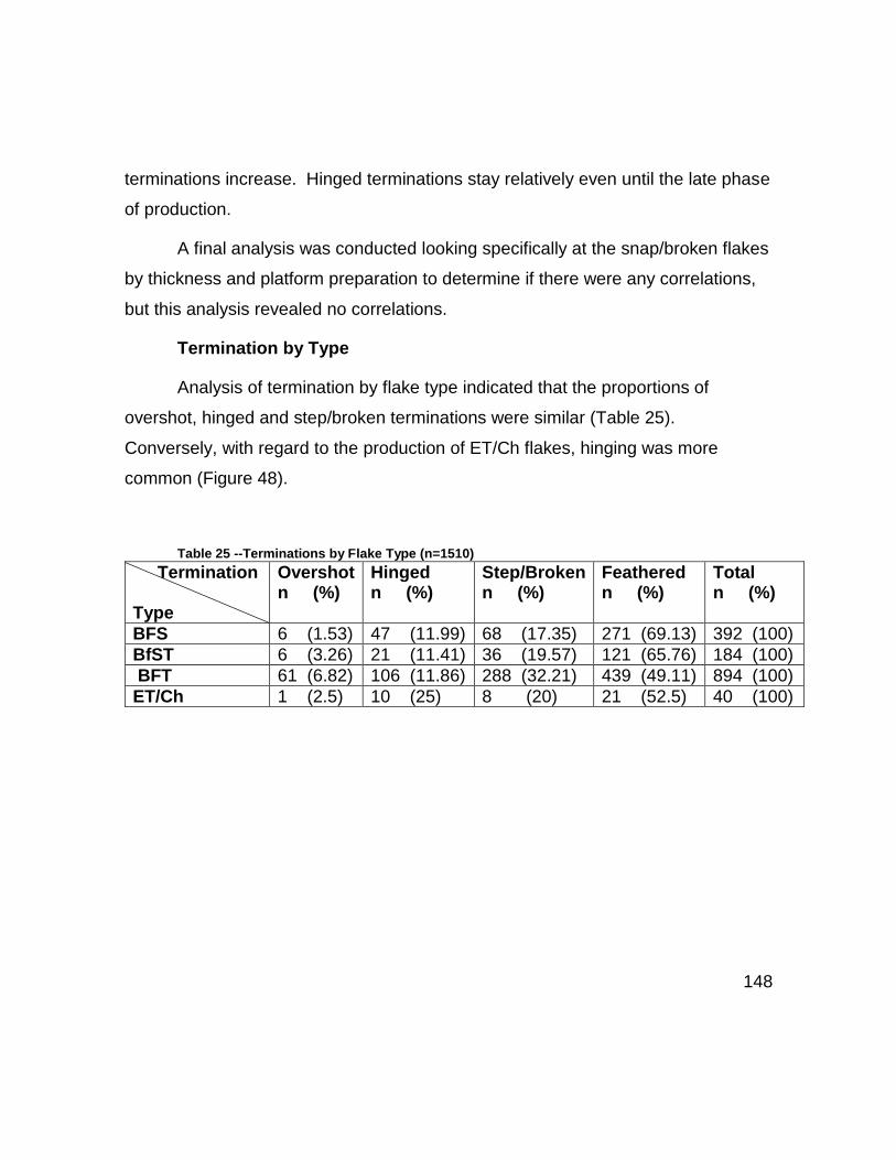
148
terminations increase. Hinged terminations stay relatively even until the late phase
of production.
A final analysis was conducted looking specifically at the snap/broken flakes
by thickness and platform preparation to determine if there were any correlations,
but this analysis revealed no correlations.
Termination by Type
Analysis of termination by flake type indicated that the proportions of
overshot, hinged and step/broken terminations were similar (Table 25).
Conversely, with regard to the production of ET/Ch flakes, hinging was more
common (Figure 48).
Table 25 --Terminations by Flake Type (n=1510)
Termination Type
Overshot n (%)
Hinged n (%)
Step/Broken n (%)
Feathered n (%)
Total n (%)
BFS 6 (1.53) 47 (11.99) 68 (17.35) 271 (69.13) 392 (100)
BfST 6 (3.26) 21 (11.41) 36 (19.57) 121 (65.76) 184 (100)
BFT 61 (6.82) 106 (11.86) 288 (32.21) 439 (49.11) 894 (100)
ET/Ch 1 (2.5) 10 (25) 8 (20) 21 (52.5) 40 (100)

149
Figure 48 -- Terminations by Flake Type
Analysis of Lipping on Platforms
Lipping on a platform is defined by Andrefsky (2005:257) as a projection on
the proximal ventral surface (strike-side) of the flake. Whittaker (1994) states,
based on the theory of soft-hammer percussion, that this load technique initiates a
bending fracture away from the actual point of contact (1994:189, fig.8.10b) which
forms a lip. However, this theory is still open to debate (see Henry, et al. 1976:57).
Lipping by Phase
Analysis of the lipping indicated that the proportions of normal, minor,
heavy, and no lipping were consistent in occurrence across all phases. These
results are presented in Table 26 and are demonstrated in Figure 49.

150
Table 26 – Lipping by Phase
Lipping Phase
Normal
n (%) Minor
n (%) Heavy
n (%) None
n (%) Total
n (%)
Early 41 (28.08) 75 (51.37) 4 (2.74) 26 (17.81) 146 (100)
Early/Middle 52 (32.1) 80 (49.38) 8 (4.94) 22 (13.58) 162 (100)
Middle 141 (32.49) 224 (51.61) 28 (6.45) 41 (9.45) 434 (100)
Middle/Late 91 (29.64) 148 (48.21) 22 (7.17) 46 (14.98) 307 (100)
Late 145 (31.45) 233 (50.54) 18 (3.9) 65 (14.1) 461 (100)
Figure 49 — Lipping by Phase
This general occurrence of lipping was confirmed using chi-squared testing
which indicated no statistically significant difference (X2(12, N=1510) = 16.09, p =
0.1871).

151
Lipping by Type
Likewise, the occurrence of lipping was evenly distributed between BFS,
BfST, and BFT flakes, and the results are presented in Table 27 and Figure 50.
Conversely, an exception to these results was the increase in normal lipping on
ET/Ch flakes that also had smaller proportions of heavy lipping and no lipping.
Table 27 -- Lipping by Flake Type (n=1510)
Lipping Type
Normal n (%)
Minor n (%)
Heavy n (%)
None n (%)
Total n (%)
BFS 99 (25.26) 204 (52.04) 14 (3.57) 75 (19.13) 392 (100) BfST 52 (28.26) 100 (54.35) 9 (4.89) 23 (12.5) 184 (100) BFT 294 (32.89) 443 (49.55) 56 (6.26) 101 (11.3) 894 (100) ET/Ch 25 (62.5) 13 (32.5) 1 (2.5) 1 (2.5) 40 (100)
Figure 50 -- Lipping by Flake Type

152
Chi-square analysis indicated that this was statistically significantly different
(X2(12, N=1510) = 42.629, p = <0.0001).
The final analysis of lipping was conducted on individual flake type groups to
determine the frequency and degree of lipping for each by phase.
While some patterns emerged in the data, including the increase in minor
lipped platforms on BFS flakes in the middle phase. Statistical analysis indicates
that there were no statistically significant differences. Table 28 and Figure 51
present the results of analysis of lipping on BFS flakes by phase. Chi-square
analysis indicated no statistically significant difference (X2(12, N=392) =20.090, p =
0.0654).
Table 28 -- Lipping on BFS Flakes by Phase
BFS Normal n (%)
Minor n (%)
Heavy n (%)
No Lip n (%)
Total n (%)
Early 14 (22.58) 28 (45.16) 2 (3.23) 18 (29.03) 62 (100)
Early/Middle 9 (21.43) 19 (45.24) 2 (4.76) 12 (28.57) 42 (100)
Middle 19 (29.23) 39 (60) 2 (3.08) 5 (7.69) 65 (100)
Middle/Late 15 (21.43) 32 (45.71) 4 (5.71) 19 (27.14) 70 (100) Late 42 (27.45) 86 (56.21) 4 (2.61) 21 (13.73) 153 (100)

153
Figure 51 -- Lipping on BFS Flakes by Phase
Table 29 and Figure 52 shows lipping on BfST flakes by phase. Chi-square
analysis could not be conducted due to the small cell values and so Fisher’s exact
Test was used instead. This test indicated no significant difference (s = 8.957, p =
0.699).
Table 29 -- Lipping on BfST by Phase (n=184)
BfST
Normal n (%)
Minor n (%)
Heavy n (%)
No Lip n (%)
Total n (%)
Early 7 (23.33) 18 (60) 1 (3.33) 4 (13.33) 30 (100) Early/Middle 9 (32.14) 16 (57.14) 1 (3.57) 2 (7.14) 28 (100) Middle 9 (21.43) 27 (64.29) 3 (7.14) 3 (7.14) 42 (100) Middle/Late 5 (22.73) 13 (59.09) 1 (4.55) 3 (13.64) 22 (100) Late 22 (35.48) 26 (41.94) 3 (4.84) 11 (17.74) 62 (100)

154
Figure 52 -- Lipping on BfST Flakes by Phase
Table 30 and Figure 53 presents the analysis of lipping on BFT flakes by
phase. Chi-square analysis indicated no statistically significant difference (X2(12,
N=894) = 7.644, p = 0.8123).
Table 30 -- Lipping on BFT Flakes by Phase (n=894)
BFT Flakes Normal n (%)
Minor n (%)
Heavy n (%)
No Lip n (%)
Total n (%)
Early 13 (28.26) 28 (60.87) 1 (2.17) 4 (8.7) 46 (100)
Early/Middle 30 (34.88) 43 (50) 5 (5.81) 8 (9.3) 86 (100)
Middle 105 (33.33) 155 (49.21) 23 (7.3) 32 (10.16) 315 (100)
Middle/Late 70 (33.33) 100 (47.62) 16 (7.62) 24 (11.43) 210 (100)
Late 76 (32.07) 117 (49.37) 11 (4.64) 33 (13.92) 237 (100)

155
Figure 53 -- Lipping on BFT Flakes by Phase
Table 31 and Figure 54 presents ET/Ch flakes by phase. Again, Chi-square
analysis could not be conducted due to small cell values, so Fisher’s exact Test
was used. This test indicated no significant difference (s =13.520 p = 0.282).
Table 31 – Lipping on ET/Ch Flakes by Phase
ET/Ch Normal n (%)
Minor n (%)
Heavy n (%)
No Lip n (%)
Total n (%)
Early 7 (87.5) 1 (12.5) 0 (0) 0 (0) 8 (100)
Early/Middle 4 (66.67) 2 (33.33) 0 (0) 0 (0) 6 (100)
Middle 8 (66.67) 3 (25) 0 (0) 1 (8.33) 12 (100)
Middle/Late 1 (20) 3 (60) 1 (20) 0 (0) 5 (100)
Late 5 (55.56) 4 (44.44) 0 (0) 0 (0) 9 (100)

156
Figure 54 -- Lipping on ET/Ch Flakes by Phase
This analysis indicates that lipping is not influenced by flake type or phase.
Analysis of platform preparation and lipping indicated no significant correlations
between any platform traits and the occurrence of lipping.
Analysis of Striking Platform Attributes and Traits
Analysis of Platform Grinding by Phase
In order to measure the intensity of grinding on striking platforms, grinding
was divided into three analytical units in order to record “where” grinding occurred
in the striking platform area -- e.g. “edge,” “obverse” (ventral), “reverse” (dorsal).
Of these, there were eight possible combinations– e.g. edge only -- obverse
only -- reverse only -- edge + obverse -- edge + reverse -- obverse + reverse – full

157
grinding (all) -- no grinding. However, only seven combinations were detected
during analysis because “obverse only” grinding was not detected on any flakes.
The counts and proportions of grinding by phase are presented in Table 32
and the proportions are illustrated in Figure 55.
Table 32 –Grinding Combinations by Phase n / %
Grinding Phase N
on
e
Ed
ge
Reve
rse
Ob
vers
e
Ed
ge +
Reve
rse
Ed
ge +
Ob
vers
e
Ob
v/R
ev
Fu
ll
To
tal
Early 49 (33.56)
38 (26.03)
0 (0)
0 (0)
5 (3.42)
29 (19.86)
0 (0) 25 (17.12)
146 (100)
Early/Mid 57 (35.19)
29 (17.9)
0 (0)
0 (0)
7 (4.32)
45 (27.78)
1 (0.62)
23 (14.2)
162 (100)
Mid 133 (30.65)
102 (23.5)
1 (0.23)
0 (0)
14 (3.23)
95 (21.89)
0 (0) 89 (20.51)
434 (100)
Mid/Late 115 (37.46)
75 (24.43)
0 (0)
0 (0)
3 (0.98)
72 (23.45)
1 (0.33)
41 (13.36)
307 (100)
Late 238 (51.63)
112 (24.3)
0 (0)
0 (0)
9 (1.95)
62 (13.45)
0 (0) 40 (8.68)
461 (100)

158
Figure 55—Platform Grinding Combinations by Phase
Two patterns present themselves in these data; the first is the decrease in
the use of grinding in the latter phases of production (indicated in Figure 55 by the
increase in the proportion of “None” or no grinding present). This is reflected by
decreasing levels of edge and obverse grinding and full grinding while the
remaining four combinations stayed relatively constant. This is confirmed with chi-
square analysis which indicated a statistically significant difference (X2(12,
N=1510) = 78.003, p = <0.0001).
Analysis of Grinding Combinations by Type
Analysis of grinding by type indicated the grinding was used in a number of
different ways and no consistent patterns of grinding combinations emerge (Table
33 and Figure 56).

159
Table 33 – PF Grinding Combinations by Type n / %
Flake Type
No
ne
Ed
ge
Reve
rse
Ob
vers
e
Ed
ge +
Reve
rse
Ed
ge +
Ob
vers
e
Ob
v/R
ev
Fu
ll
To
tal
BFS 250 (63.78)
75 (19.13)
(0) (0) 5 (1.28)
42 (10.71)
(0) 20 (5.1) 392 (100)
BfST 70 (38.04)
49 (26.63)
(0) (0) 6 (3.26)
37 (20.11)
(0) 22 (11.96)
184 (100)
BFT 261 (29.19)
223 (24.94)
1(0.11) (0) 26 (2.91)
218 (24.38)
2 (0.22)
163 (18.23)
894 (100)
ET/Ch 11 (27.5) 9 (22.5) (0) (0) 1 (2.5) 6 (15) (0) 13 (32.5) 40 (100)
Figure 56 – Grinding Combinations by Type

160
Chi-square analysis indicated that there were statistically significant
differences in the use of grinding (X2(12, N=1510) = 78.003, p = <0.0001).
Analysis of standardized residuals indicates this is due to the higher than expected
occurrence of no grinding for BFS flakes.
Presence or Absence of Grinding
The analysis was simplified to look at cases where grinding was compared
based on presence or absence. This is presented by phase in Table 34. This
analysis shows that while the combinations of grinding showed differences in their
application, the use of grinding in some form was a relatively common method of
platform preparation. Figure 57 illustrates this and highlights that in the final phase
of production, grinding was used slightly less.
Table 34 -- Presence/Absence of Grinding by Phase (n=1510)
Present n (%)
Absent n (%)
Early 97 (66.44) 49 (33.56)
Early/Middle 105 (64.81) 57 (35.19)
Middle 301 (69.35) 133 (30.65)
Middle/Late 192 (62.54) 115 (37.46)
Late 223 (48.37) 238 (51.63)

161
Figure 57 -- Presence/Absence of PF Grinding by Phase
Analysis of the presence or absence of grinding by flake type presented in
Table 35 and Figure 58 indicated that BFS flakes generally had less grinding on
them than any other flake type.
Table 35 -- Presence/Absence of PF Grinding by Type (n=1510)
Present n (%)
Absent n (%)
BFS 142 (36.22) 250 (63.78) BfST 114 (61.96) 70 (38.04) BFT 633 (70.81) 261 (29.19) ET/Ch 29 (72.5) 11 (27.5)

162
Figure 58-- Presence/Absence of Grinding by Type
A final analysis was conducted looking at grinding by flake type and phase.
The analysis of this is presented in Table 36 and Figure 59 for BFS flakes, Table
37 and Figure 60 for BfST flakes, Table 38 and Figure 61 for BFT flakes, and Table
39 and Figure 62 for ET/Ch flakes. Due to the small cell values for grinding by
phase and type it was not possible to run any form of statistical analysis on these
data. What is clear from this analysis is the same pattern of increasing levels of
unground flakes towards the late phase of production.
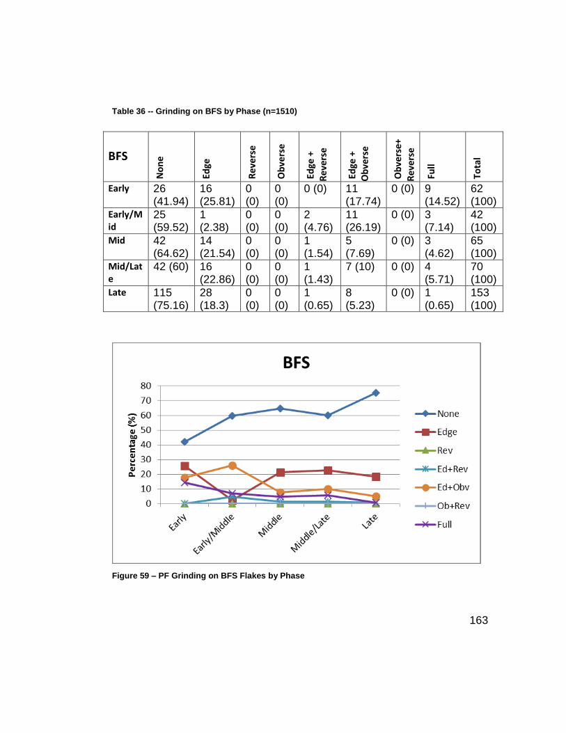
163
Table 36 -- Grinding on BFS by Phase (n=1510)
Figure 59 – PF Grinding on BFS Flakes by Phase
BFS
No
ne
Ed
ge
Re
vers
e
Ob
vers
e
Ed
ge +
Re
vers
e
Ed
ge +
O
bve
rse
Ob
vers
e+
Re
vers
e
Fu
ll
To
tal
Early 26 (41.94)
16 (25.81)
0 (0)
0 (0)
0 (0) 11 (17.74)
0 (0) 9 (14.52)
62 (100)
Early/Mid
25 (59.52)
1 (2.38)
0 (0)
0 (0)
2 (4.76)
11 (26.19)
0 (0) 3 (7.14)
42 (100)
Mid 42 (64.62)
14 (21.54)
0 (0)
0 (0)
1 (1.54)
5 (7.69)
0 (0) 3 (4.62)
65 (100)
Mid/Late
42 (60) 16 (22.86)
0 (0)
0 (0)
1 (1.43)
7 (10) 0 (0) 4 (5.71)
70 (100)
Late 115 (75.16)
28 (18.3)
0 (0)
0 (0)
1 (0.65)
8 (5.23)
0 (0) 1 (0.65)
153 (100)

164
Table 37 -- Grinding on BfST by Phase
BfST
No
ne
Ed
ge
Re
vers
e
Ob
vers
e
Ed
ge +
Re
vers
e
Ed
ge +
Ob
vers
e
Ob
vers
e+
Re
vers
e
Fu
ll
To
tal
Early 8 (26.67)
8 (26.67)
0 (0)
0 (0)
2 (6.67)
9 (30) 0 (0)
3 (10) 30 (100)
Early/Mid
7 (25) 6 (21.43)
0 (0)
0 (0)
2 (7.14)
9 (32.14)
0 (0)
4 (14.29)
28 (100)
Mid 16 (38.1)
9 (21.43)
0 (0)
0 (0)
2 (4.76)
10 (23.81)
0 (0)
5 (11.9) 42 (100)
Mid/Late
8 (33.33)
9 (37.5)
0 (0)
0 (0)
2 (8.33)
3 (12.5)
0 (0)
2 (8.33) 24 (100)
Late 31 (50) 17 (27.42)
0 (0)
0 (0)
0 (0) 6 (9.68)
0 (0)
8 (12.9) 62 (100)
Figure 60 -- PF Grinding on BfST Flakes by Phase

165
Table 38 – PF Grinding on Biface Thinning Flake by Phase (n=1510)
Figure 61 – PF Grinding on BFT Flakes by Phase
BFT
No
ne
Ed
ge
Re
vers
e
Ob
vers
e
Ed
ge +
Re
v
Ed
ge +
Ob
v
Ob
v+ R
ev
Fu
ll
To
tal
Early 10 (21.74)
12 26.09)
0 (0) 0 (0)
3 (6.52)
9 (19.57)
0 (0) 12 (26.09)
46 (100)
Early/Mid
24 (27.91)
20 (23.26)
0 (0) 0 (0)
3 (3.49)
24 (27.91)
1 (1.16)
14 (16.28)
86 (100)
Mid 73 (23.17)
78 (24.76)
1 (0.32)
0 (0)
10 (3.17)
78 (24.76)
0 (0) 75 (23.81)
315 (100)
Mid/Late
63 (30.29)
48 (23.08)
0 (0) 0 (0)
0 (0) 61 (29.33)
1 (0.48)
35 (16.83)
208 (100)
Late 91 (38.4)
65 (27.43)
0 (0) 0 (0)
8 (3.38)
46 (19.41)
0 (0) 27 (11.39)
237 (100)

166
Table 39 – PF Grinding on ET/Ch Flakes by Phase
Figure 62 -- PF Grinding on ET/Ch Flakes by Phase
ET/Ch
No
ne
Ed
ge
Reve
rse
Ob
vers
e
Ed
ge +
Reve
rse
Ed
ge +
Ob
vers
e
Ob
vers
e+
Reve
rse
Fu
ll
To
tal
Early 5(62.5) 2(25) 0(0) 0(0) 0(0) 0(0) 0(0) 1(12.5) 8(100)
Early/Mid 1(16.67) 2(33.33) 0(0) 0(0) 0(0) 1(16.67) 0(0) 2(33.33) 6(100)
Middle 2(16.67) 1(8.33) 0(0) 0(0) 1(8.33) 2(16.67) 0(0) 6(50) 12(100)
Mid/Late 2(40) 2(40) 0(0) 0(0) 0(0) 1(20) 0(0) 0(0) 5(100)
Late 1(11.11) 2(22.22) 0(0) 0(0) 0(0) 2(22.22) 0(0) 4(44.44) 9(100)

167
A question was raised during the analysis if heavy grinding influenced
platform shapes. Analysis of those platforms that were heavily ground indicated
that 80 (36.7%) were convex while 71 (32.57%) were straight, 64 (29.36%) were
indeterminate and only 3 were concave (1.38 %). When compared to the general
frequencies of these shapes, the data indicate that the levels of heavily ground
platforms are proportionate to the numbers present in the entire assemblage.
Platform shapes by phase and flake type are analyzed later in this section.
Platform Status
Three attributes relating to the state of the platform were recorded as
cortical, plain, and remnants that had been shattered or crushed.
Analysis of Remnant /Shattered/Crushed Platforms
Rem/Shattered/Crushed by Phase
Analysis of the remnant, shattered, or crushed platforms indicated that the
general trend was an increase in the proportions of this type but there was a
noticeable peak during the middle phases of manufacture (Table 40 and Figure
63).

168
Table 40 – Remnant/Shattered/Crushed Platforms by Phase
Phase Rem/Shattered/Crushed n (%)
Early 9 (7.09)
Early/Middle 14 (11.02)
Middle 41 (32.28)
Middle/Late 24 (18.9)
Late 39 (30.71)
Total 127 (100)
Figure 63 – Remnant/Shattered/Crushed Platforms by Phase
Rem/Shattered/Crushed by Type
Analysis of the remnant, shattered, or crushed platforms by type indicated
that there was a high incidence of this in the production of BFT flakes (Table 41
and Figure 64).

169
Table 41 – Remnant/Shattered/Crushed Platforms by Type
Platform by Flake Type
Rem/shattered/crushed n (%)
BFS 23 (18.11)
BfST 12 (9.45)
BFT 89 (70.08)
ET/Ch 3 (2.36)
Total 127 (100)
Figure 64 -- Remnant, Shattered, or Crushed Platforms by Flake Type

170
Analysis of Plain Platforms
Remnant, shattered, or crushed platforms were removed from this next
analysis as shattered platforms made it difficult to determine if a “plain” platform
was truly plain.
Plain Platforms by Phase
Analysis of the plain platforms (Table 42 and Figure 65) indicated that there
was a slight increase in the use of plain platforms in the middle and late phase
however, generally the number remained consistent.
Table 42 -- Plain Platforms by Phase
by Phase Plain n %
Early 22 (18.18)
Early/Middle 22 (18.18)
Middle 28 (23.14)
Middle/Late 21 (17.36)
Late 28 (23.14)
Total 121 (100)

171
Figure 65 -- Plain Platforms by Phase
Included within this sample was a small number of platforms (n=8, 21.62%)
that were recorded as plain and cortical.
Plain Platforms by Type
Comparison by type indicated that plain platforms were used most
extensively on BFS flakes (Table 43 and Figure 66).
Table 43 -- Plain Platforms by Flake Type
Flake Type Plain n (%)
BFS 64 (52.89)
BfST 9 (7.44)
BFT 46 (38.02)
ET/Ch 2 (1.65)
Total 121 (100)

172
Figure 66 -- Plain Platforms by Flake Type
Analysis of Cortical Platforms
Cortical Platforms by Phase
Analysis of cortical platforms by phase indicated that, while there was a
general overall trend in the decline of cortical platforms, both the middle and late
phase had higher proportions of cortex (Table 44 and Figure 67).
Table 44 -- Cortical Platforms by Phase
Phase Cortical n (%)
Early 87 (21.91)
Early/Middle 73 (18.39)
Middle 101 (25.44)
Middle/Late 55 (13.85)
Late 81 (20.4)
Total 397(100)

173
Figure 67 -- Cortical Platforms by Phase
Cortical Platforms by Type
Cortical platforms were most common on BFT flakes, followed by BFS
flakes (Table 45 and Figure 68).
Table 45 -- Cortical Platforms by Type
Flake Type Cortical n (%)
BFS 134 (33.75)
BfST 46 (11.59)
BFT 208 (52.39)
ET/Ch 9 (2.27)
Total 397 (100)

174
Figure 68 -- Cortical Platforms by Type
Statistical Analysis of Platform States (Platform Status/Condition)
Statistical analysis using chi-square tests indicated that there was a
statistically significant difference in the distribution of plain (p=<0.0001) and cortical
(p=<0.0001) platforms by phase (Table 46).
Table 46 -- Chi-square Test of Platform State by Phase
X2 df p-value
Plain 32.051 4 <0.0001
Cortical 144.232 4 <0.0001
Rem/shat/crushed 1.714 4 0.7881

175
The significant differences are derived from higher than expected
occurrence of plain platforms during the middle and late phases, and the higher
than expected occurrence of cortical platforms in the middle phases, as well as a
lower than expected occurrence of cortical platforms in the late phases.
Chi-square analysis of platform state by type (Table 47) Indicated that there
was a statistically significant difference in the distribution of plain (p=<0.0001) and
cortical (p=0.0006).
Table 47 -- Chi-square Test of Platform State by Type
The significant differences are derived from the higher than expected
occurrence of plain platforms for BFS flakes and the higher than expected
occurrence of plain platforms in BFT flakes.
Analysis of Platform Shape
Platform shapes were recorded as straight, concave, convex, and dihedral.
However, some platform shapes were recorded as ‘indeterminate’ due to their
ambiguous nature. All were analyzed for significance by phase and flake type.
Shape by Phase
The results presented in Table 48 indicate that straight platforms appear in
higher percentages in the early and late phases. The percentage of concave
platforms increased towards the late phase of biface production with convex
df X2 p-value
Plain 3 36.861 <0.0001
Cortical 3 17.277 0.0006
Rem/shat/crushed 3 6.956 0.0733

176
platforms being most prevalent in the middle and middle/late phases. These
results are also presented in Figure 69.
Table 48 – Platform Shapes by Phase
Shape
Phase
Straight n (%)
Convex n (%)
Dihedral n (%)
Concave n (%)
Indet. n (%)
Total n (%)
Early 57 (39.04) 27 (18.49) 16 (10.96) 3 (2.05) 43 (29.45) 146(100)
Early/Mid 52 (32.10) 39 (24.07) 17 (10.49) 10 (6.17) 44 (27.16) 161(100)
Mid 144(33.18) 142(32.72) 28 (6.45) 23 (5.3) 97 (22.35) 434(100)
Mid/Late 98 (31.92) 99 (32.25) 27 (8.79) 22 (7.17) 61 (19.87) 307(100)
Late 194(42.08) 112(24.30) 33 (7.16) 49 (10.63) 73 (15.84) 461(100)
Figure 69 -- Platform Shapes by Phase

177
Chi-square testing indicated that there was a statistically significant
difference in the distribution of shape (X2(16, N=1510) = 56.132, p = <0.0001).
Further analysis of the standardized residuals of platform shape by phase show the
significance is derived from the lower than expected counts of concave and convex
platforms in the early phase, as well as higher than expected straight platforms in
the late phase.
Shape by Type
Analysis indicated that the percentages of platform shapes in BFS flakes
and BfST flakes were relatively similar in distribution (Table 49 and Figure 70).
However, percentages of straight platforms were higher for BFT flakes, with ET/Ch
flakes having a nearly equal distribution percentage of platforms that were straight
or convex.
Table 49 -- Platform Shape by Type
Shape Type
Straight n (%)
Convex n (%)
Dihedral n (%)
Concave n (%)
Indeterminate n (%)
Total n (%)
BFS 124 (31.63) 87 (22.19) 68 (17.35) 32 (8.16) 81 (20.66) 392 (100)
BFST 64 (34.78) 45 (24.46) 20 (10.87) 9 (4.89) 46 (25) 184 (100)
BFT 345 (38.59) 274 (30.65) 28 (3.13) 64 (7.16) 183 (20.47) 894 (100)
ET/Ch 12 (30) 13 (32.5) 5 (12.5) 2 (5) 8 (20) 40 (100)
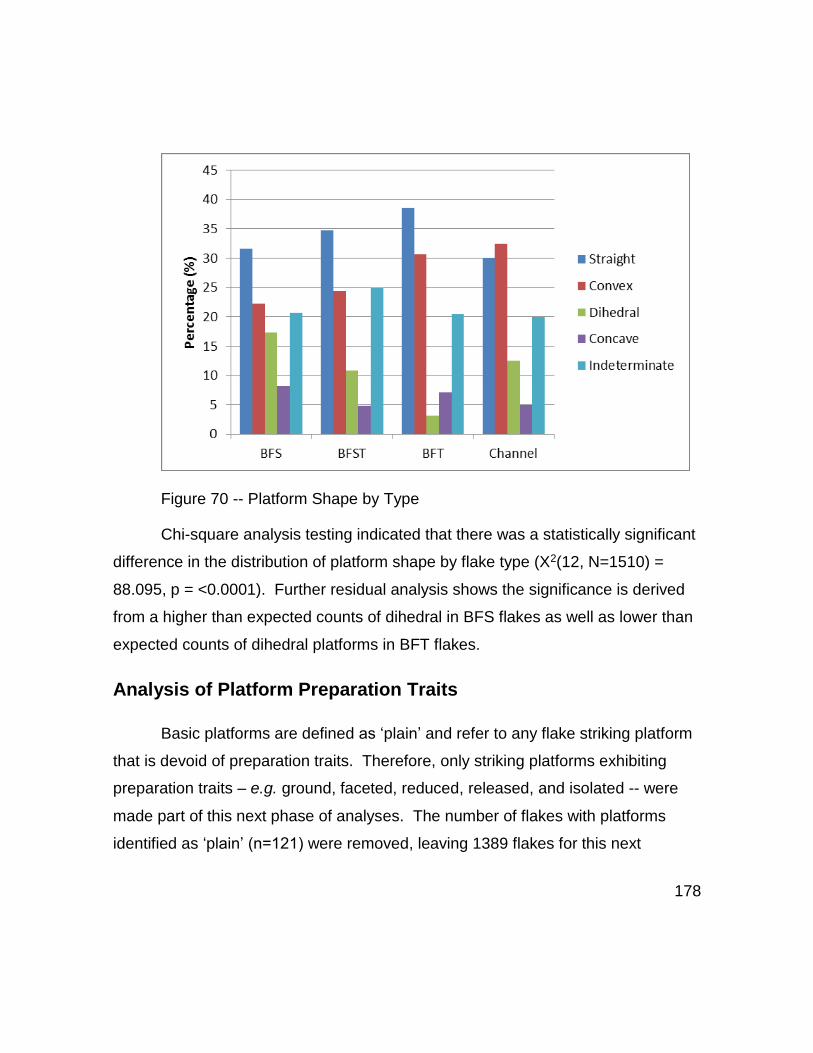
178
Figure 70 -- Platform Shape by Type
Chi-square analysis testing indicated that there was a statistically significant
difference in the distribution of platform shape by flake type (X2(12, N=1510) =
88.095, p = <0.0001). Further residual analysis shows the significance is derived
from a higher than expected counts of dihedral in BFS flakes as well as lower than
expected counts of dihedral platforms in BFT flakes.
Analysis of Platform Preparation Traits
Basic platforms are defined as ‘plain’ and refer to any flake striking platform
that is devoid of preparation traits. Therefore, only striking platforms exhibiting
preparation traits – e.g. ground, faceted, reduced, released, and isolated -- were
made part of this next phase of analyses. The number of flakes with platforms
identified as ‘plain’ (n=121) were removed, leaving 1389 flakes for this next

179
analysis. Furthermore, grinding will be included, but will be simplified as a
presence or absence trait.
Preparation by Phase
Table 50 presents flake counts and percentages of platform preparation
traits by phase. Analysis indicated that the occurrence of ground platforms
progressively declined from early to late phases and supports previous findings.
Conversely, the percentage of reduced and isolated traits increased as phases
progressed. While released and faceted reflect a slight increase in the middle
phase, they remain relatively consistent. This is illustrated in Figure 71.
Table 50 -- Platform Preparation by Phase*
Prep Phase
Ground n (%)
Faceted n (%)
Reduced n (%)
Released n (%)
Isolated n (%)
Total n (%)
Early 97 (28.87) 49 (14.58) 89 (26.49) 30 (8.93) 71 (21.13) 336(100)
Early/Mid 105(25.06) 75 (17.9) 95 (22.67) 47 (11.22) 97 (23.15) 419 (100)
Mid 301(22.99) 248(18.95) 317(24.22) 142(10.85) 301(22.99) 1309 (100)
Mid/Late 192(23.08) 148(17.79) 206(24.76) 79 (9.5) 207(24.88) 832(100)
Late 223(19.44) 187(16.3) 33 (29.47) 80 (6.97) 319(27.81) 1147(100)
* counts and percentages do always not equal 100
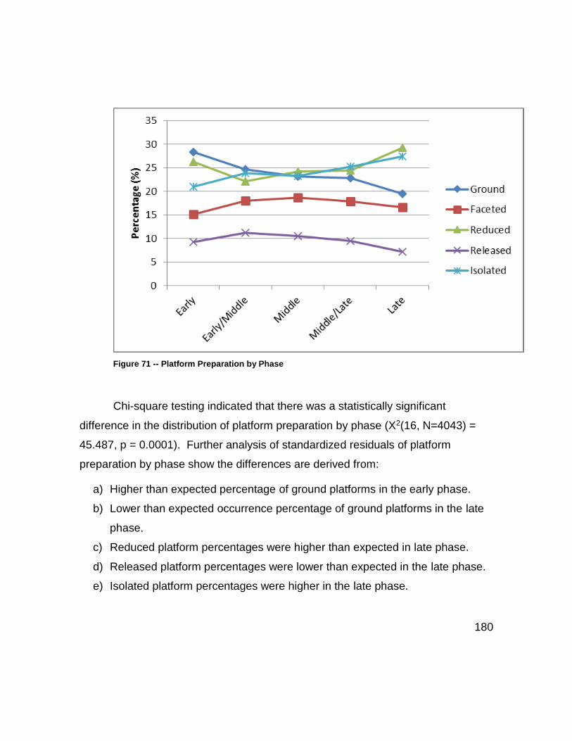
180
Figure 71 -- Platform Preparation by Phase
Chi-square testing indicated that there was a statistically significant
difference in the distribution of platform preparation by phase (X2(16, N=4043) =
45.487, p = 0.0001). Further analysis of standardized residuals of platform
preparation by phase show the differences are derived from:
a) Higher than expected percentage of ground platforms in the early phase.
b) Lower than expected occurrence percentage of ground platforms in the late
phase.
c) Reduced platform percentages were higher than expected in late phase.
d) Released platform percentages were lower than expected in the late phase.
e) Isolated platform percentages were higher in the late phase.

181
Preparation by Type
Analysis of platform preparation traits by flake type indicates a complex
pattern of use (Table 51 and Figure 72). Overall, the relative percentages of each
trait are similar across each flake type; however, some trends do occur. BFS
flakes have the highest number of platforms that are reduced. On BFT flakes,
isolated platforms are the most common preparation trait, followed by ground, and
reduced platforms. ET/Ch flakes reveal that reduced and ground platforms were
the most common.
Table 51 -- Platform Preparation by Type*
Ground n (%)
Faceted n (%)
Reduced n (%)
Released n (%)
Isolated n (%)
Total n (%)
BFS 142 (19.75) 101 (14.05) 248 (34.49) 39 (5.42) 189 (26.29) 719 (100) BFST 114 (22.31) 88 (17.22) 136 (26.61) 54 (10.57) 119 (23.29) 511 (100) BFT 633 (23.45) 496 (18.38) 632 (23.42) 272 (10.08) 666 (24.68) 2699 (100) ET/Ch 29 (25.44) 22 (19.3) 29 (25.44) 13 (11.4) 21 (18.42) 114 (100)
*do not always equal 100

182
Figure 72 -- Platform Preparation by Type
Chi-square testing indicated that there was a statistically significant
difference in the distribution of platform preparation by type (X2(12, N=4043) =
54.918, p = <0.0001). Standardized residual analysis reveal the significance
comes from BFS flakes which reveal a lower than expected count (n =) of Faceted,
Ground and Released platform traits as well as a higher than expected (n =) of
Reduced.
Platform Preparation Correlation Analysis
Before continuing platform trait analysis, a decision was made to conduct a
correlation analysis to determine if the platform preparation traits were
independent, or, if any of the preparation traits were used systematically in
conjunction with each other. As the present data set consists of presence/absence

183
data, non-parametric correlation tests were conducted using Spearman’s P and
Hoeffding’s D and Table 52 presents the results of this analysis by trait groupings.
Spearman’s ρ correlation indicates a perfect-positive relationship at +1 with
a perfect-negative relationship at -1. Trait group “Reduced by Faceted’ is -0.07
indicates that there is almost no relationship present and that this is not statistically
significant (p=0.0158). The results of all remaining groups of two variables indicate
weak-positive relationships that are statistically significant. These results were
then confirmed by applying Hoeffding’s D, which measures the difference between
the two variables in each group and the product of their marginal ranks.
Hoeffding’s D confirms the weak relationship (Spearman’s ρ) between the
remaining group’s two variables.
The results of this correlation analysis indicate that while these traits
(faceted, ground, reduced, released, isolated) do occur together, the relationship,
in terms of correlation, is weak which concludes that the platform preparation traits
are not dependent upon any others.
Table 52 -- Platform Trait-Non-parametric Correlation Tests
Trait by Trait Groupings
Spearman’s ρ
Prob>|ρ| Hoeffding’s D
Prob>D
Faceted Ground 0.24 <.0001 0.0054 <.0001
Reduced Ground 0.1459 <.0001 0.001 0.022
Reduced Faceted -0.0657 0.0158 -0.0004 0.9985
Released Ground 0.2804 <.0001 0.0058 <.0001
Released Faceted 0.1996 <.0001 0.0028 0.0003
Released Reduced 0.1912 <.0001 0.0018 0.0032
Isolated Ground 0.2011 <.0001 0.0029 0.0002
Isolated Faceted 0.1962 <.0001 0.003 0.0002
Isolated Reduced 0.2123 <.0001 0.0027 0.0004
Isolated Released 0.3582 <.0001 0.009 <.0001

184
Platform Preparation Complexity by Score
A common characteristic ascribed to Clovis flake platforms is that they were
complex, but the level of complexity is not understood. Using the same delineation
for platform preparation traits, platforms were assigned a score based on how
many preparation traits were present. In this respect, a score of “1” equates to one
preparation trait present, while a score of “5” indicates all five traits were present.
This was then used as a proxy for complexity: Wherein the numbers of traits likely
denote the extent of attention given (knapping behaviors) during biface reduction
and/or flake production.
Analysis of Platform Preparation Scores
Preparation Scores By Phase
The first analysis looked at the distribution in terms of relative percentages
of platform scores by phase presented in Table 53 and Figure 73.
Table 53 -- Platform Scores by Phase
Score by
Phase
1 n (%)
2 n (%)
3 n (%)
4 n (%)
5 n (%)
Total n (%)
Early 28(22.58) 31 (25) 28 (22.58) 23 (18.55) 14 (11.29) 124 (100) Early/Mid 27(19.29) 29 (20.71) 27 (19.29) 32 (22.86) 25 (17.86) 140 (100) Mid 43(10.59) 88 (21.67) 91 (22.41) 103(25.37) 81 (19.95) 406 (100) Mid/Late 41(14.34) 84 (29.37) 70 (24.48) 42 (14.69) 49 (17.13) 286 (100) Late 74(17.09) 144 (33.26) 110 (25.4) 70 (16.17) 35 (8.08) 433 (100)

185
Figure 73 -- Platform Scores by Phase
While the analysis indicates no strong correlation in the data, platform
scores appear to alternate throughout production and follow no set pattern. Chi-
square analysis indicates there is a statistically significant difference (X2(20,
N=1389) = 65.671, p = <0.0001). Analysis of the standardized residuals reveal
that the statistical differences are derived from statistically higher than expected
counts of platforms scoring “1” in the early phase, and statistically lower than
expected counts of platforms with scores of “1” and “2” in the middle phase.
Analysis also indicated that a score of “4” and “5” was statistically higher than
expected in the middle phase.

186
Preparation Scores by Type
An analysis of platform scores by flake type reveals a similar pattern above
that indicates more complex behaviors, which are presented in Table 54 and
Figure 74. BFS had the highest percentage of platforms scoring “1” and “2.” The
platforms on ET/Ch flakes reveal all platforms were prepared to some degree.
BFT flakes and ET/Ch had the highest percentage of platforms scoring “4” and “5.”
Table 54 -- Platform Scores by Type
PF Score by
Flake Type
1 n (%)
2 n (%)
3 n (%)
4 n (%)
5 n (%)
Total n (%)
BFS 93 (28.35) 133(40.55) 63 (19.21) 24 (7.32) 15 (4.57) 32 (100)
BFST 27 (15.43) 45 (25.71) 42 (24) 37 (21.14) 24 (13.71) 175(100)
BFT 83 (9.79) 192(22.64) 217(25.59) 199(23.47) 157 (18.51) 848(100)
ET/Ch 10 (26.32) 6 (15.79) 4 (10.53) 10 (26.32) 8 (21.05) 38 (100)
Figure 74 -- Platform Scores by Type

187
Chi-square analysis indicated a statistically significant difference (X2(12,
N=1389) = 158.737, p = <0.0001) in platform scores by type. Further analysis of
the standardized residuals indicated that this was derived from the higher
proportions of scores “1” and “2” in BFS flakes, compared with lower than expected
percentages of “4” and “5” as well in BFS. Analysis also indicated that BFT flakes
had a higher than expected percentage of platforms scoring “4” and “5” compared
to other flakes with the same scores and compared to BFT platforms scoring “1”
and “2”.
These results were further explored by calculating the mean average
platform score for each phase. The results reveal that the middle phase had the
highest average platform scores, while the early and late phases had the lowest
(Fig. 75).
Figure 75 -- Mean Average Platform Score for Each Phase. (y axis = average score)

188
Average platform scores for each type indicated that BFT flakes and ET/Ch
flakes had the highest average platform scores (Fig. 76), but overall indicate no
emerging pattern.
Figure 76 -- Mean Average Platform Score for Each Type (y axis = average score)
Analysis of Platform Complexity – Preparation Traits in Flake Types by Phase
Platform complexity was further explored of individual flake groups (BFS,
BFT, BfST, and ET/Ch) in order to analyze the complexities of each by preparation
trait and phase for any detectable patterns.

189
BFS Flakes by Trait and Phase
Table 55 and Figure 77 present the results of platform preparation on BFS
flakes.
Table 55 –BSF Flakes -- Platform Preparation Traits by Phase
Trait by
Phase
Ground n (%)
Faceted n (%)
Reduced n (%)
Released n (%)
Isolated n (%)
Total n (%)
Early 36 (31.03) 11 (9.48) 36 (31.03) 10 (8.62) 23 (19.83) 116 (100)
Early/Mid 17 (26.56) 10 (15.63) 17 (26.56) 6 (9.38) 14 (21.88) 64 (100)
Mid 23 (20.35) 23 (20.35) 38 (33.63) 4 (3.54) 25 (22.12) 113 (100)
Mid/Late 28 (20.14) 18 (12.95) 47 (33.81) 8 (5.76) 38 (27.34) 139 (100)
Late 38 (13.24) 39 (13.59) 110 (38.33) 11 (3.83) 89 (31.01) 287 (100)
Figure 77 – BFS Flakes --Platform Preparation Trait by Phase
Chi-square analysis indicated a statistically significant difference X2(16,
N=719) = 34.894, p = 0.0041. However, analysis of standardized residuals

190
indicate the significance is derived from BFS flakes having higher than expected
occurrence of ground platforms in the early phase and lower than expected
occurrence of ground platforms in the late phase.
BfST Flakes by Trait and Phase
The results of the analysis on BfST flakes is presented in Table 56 and
illustrated in Figure 78.
Table 56 -- BfST Flakes -- Platform Preparation Traits by Phase
Trait by
Phase
Ground n (%)
Faceted n (%)
Reduced n (%)
Released n (%)
Isolated n (%)
Total n (%)
Early 22 (26.51) 15 (18.07) 21 (25.3) 8 (9.64) 17 (20.48) 83 (100)
Early/Middle 21 (26.25) 14 (17.5) 17 (21.25) 10 (12.5) 18 (22.5) 80 (100)
Middle 26 (19.7) 21 (15.91) 34 (25.76) 21 (15.91) 30 (22.73) 131 (100)
Middle/Late 14 (27.45) 9 (17.65) 13 (25.49) 4 (7.84) 11 (21.57) 51 (100)
Late 31 (18.79) 29 (17.58) 51 (30.91) 11 (6.67) 43 (26.06) 165(100)

191
Figure 78 – BfST Flakes - Platform Preparation Traits by Phase
Chi-square analysis indicated no significant difference in platform
preparation traits BfST flakes by phase X2(16, N=511) = 13.026, p = 0.6709.
BFT Flakes by Trait and Phase
Analysis of BFT flakes indicated little variation in the percentages of these
traits by phase (Table 57 and Figure 79).
Table 57 – BFT Flakes - Platform Percentage Preparation Traits by Phase
Trait By
Phase
Ground n (%)
Faceted n (%)
Reduced n (%)
Released n (%)
Isolated n (%)
Total n (%)
Early 36 (27.91) 22 (17.05) 29 (22.48) 12 (9.3) 30 (23.26) 129 (100)
Early/Middle 62 (24.03) 49 (18.99) 57 (22.09) 28 (10.85) 62 (24.03) 258 (100)
Middle 242 (23.73) 195 (19.12) 234 (22.94) 111 (10.88) 238 (23.33) 1020 (100)
Middle/Late 147 (23.41) 118 (18.79) 143 (22.77) 65 (10.35) 155 (24.68) 628 (100)
Late 146 (21.99) 112 (16.87) 169 (25.45) 56 (8.43) 181 (27.26) 664 (100)

192
Figure 79 – BFT Flakes – Preparation Traits by Phase
Chi-square analysis confirmed this finding indicating no statistically
significant difference in platform preparation traits in BFT flakes by phase X2(16,
N=2699) = 10.159, p = 0.8582.
Platform Complexity of ET/Ch Flakes by Trait and Phase
Analysis of ET/Ch flakes are presented in Table 58 and illustrated in Figure
80.

193
Table 58 – ET/Ch – Percentage of Preparation Traits by Phase
Trait by
Phase
Ground n (%)
Faceted n (%)
Reduced n (%)
Released n (%)
Isolated n (%)
Total n (%)
Early 3 (37.5) 1 (12.5) 3 (37.5) 0 (0) 1 (12.5) 8 (100) Early/Mid 5 (29.41) 2 (11.76) 4 (23.53) 3 (17.65) 3 (17.65) 17 (100) Middle 10 (22.73) 9 (20.45) 11 (25) 6 (13.64) 8 (18.18) 44 (100) Mid/Late 3 (21.43) 3 (21.43) 3 (21.43) 2 (14.29) 3 (21.43) 14 (100) Late 8 (25.81) 7 (22.58) 8 (25.81) 2 (6.45) 6 (19.35) 31 (100)
Figure 80 – (ET/Ch) Flakes –Platform Preparation Traits by Phase
Due to the small sample size of ET/Ch flakes, Fisher’s Exact Test was used
in lieu of Chi-square, to deal with analyzing small or unequal proportions. Analysis
indicated that there was no statistically significant difference (p = 0.994).

194
Analysis of Platform Complexity in Flakes with Overshot Terminations
(OST)
This next section further refines the 1510 data set by analyzing only those
flakes recorded with overshot terminations (OST). Seventy-four flakes with
overshot terminations (OST) were identified as being associated with biface
reduction and were analyzed by flake type and phase to determine the levels of
platform preparation traits. The results of this analysis will be used later to help
inform the separate supplement overshot study presented in Chapter 9.
OST by Phase
Platform traits on overshot terminations (OST) were first analyzed by phase
to assess their distribution. Table 59 and Figure 81 present results of these data.
Table 59 – Platform Preparation Traits on Overshot Terminations by Phase
Traits By
Phase
Ground n (%)
Faceted n (%)
Reduced n (%)
Released n (%)
Isolated n (%)
Total *reflects more
than actual # of flakes in sample
Early 22 (26.51) 14 (16.87) 19 (22.89) 9 (10.84) 19 (22.89) 83 (100)
Early/Middle 3 (23.08) 3 (23.08) 2 (15.38) 2(15.38) 3 (23.08) 13 (100)
Middle 28 (24.78) 23 (20.35) 29 (25.66) 12 (10.62) 21 (18.58) 113 (100)
Middle/Late 5 (25) 3 (15) 3 (15) 3 (15) 6 (30) 20 (100)
Late 5 (20) 6 (24) 5 (20) 2 (8) 7 (28) 25 (100)

195
Figure 81 – Platform Preparation Traits on OS Terminations by Phase
Analysis indicates all but one of the overshot termination platforms by phase
were prepared and these preparation traits are found in various combinations. Chi-
square statistical analysis reveal no statistically significant difference in the
distribution of these traits by phase (X2(12, N=254) = 4.938, p = 0.9961).
OST by Type
Platform traits on flakes with overshot terminations were analyzed by flake
type (Table 60 and Fig. 82).

196
Table 60 – Platform Preparation Traits on Overshot Terminations by Flake Type
Traits by
Type
Ground
n (%)
Faceted
n (%)
Reduced
n (%)
Released
n (%)
Isolated
n (%)
Total
n (%)
BFS 4 (33.33) 0 (0) 5 (41.67) 0 (0) 3 (25) 12 (100)
BFST 4 (21.05) 4 (21.05) 4 (21.05) 2 (10.53) 5 (26.32) 19 (100)
BFT 54 (24.77) 44 (20.18) 48 (22.02) 25 (11.47) 47 (21.56) 218 (100)
Channel 1 (20) 1 (20) 1 (20) 1 (20) 1 (20) 5 (100)
Figure 82 – Platform Preparation on OS Terminations by Flake Type
Results indicate that twelve BFS flakes with overshot terminations were not
faceted or released.
These results raise an interesting paradox of an overshot termination being
identified as a ‘shaping’ flake as defined in Chapter 6. A closer look at the raw
data shows that twelve BFS flake specimens were assigned to early biface

197
reduction phases and retained square and/or cortical edges. While overshots in
general affect both sides of the objective biface piece, they do not fit within the
definition used here in the strictest sense because these had a simultaneous effect
on two lateral edges of the objective biface. Based on the mechanics of plunging
flakes, the BFS flake terminations likely removed more mass from at least one
lateral edge to create workable edges and may indicate that not all overshot flakes
were strictly used for thinning.
Regarding the only ET/Ch in this sample with an overshot/plunging
termination retained a platform that was well prepared exhibiting all five platform
preparation traits. This is interesting since this particular ET/Ch flake ruined a
Clovis preform.
Statistical analysis indicated that no statistically significant differences were
found in the distribution of these platform traits by type (X2(12, N=254) = 6.884, p =
0.8652).
OST Platform Preparation Score
This analysis indicated that flakes with overshot terminations were prepared
prior to detachment and that heavy preparation occurred across all phases and on
different flake types. Further analysis of these platform terminations indicated an
average platform trait-use score of 3.43. Analysis of overshot flake platforms
indicated that nineteen (19) different trait combinations were used. The most
common combination was the use of all five traits in sixteen (16) specimens
representing 21.62% of this OST data set. These data strongly suggest that
platforms on OS terminated flakes had carefully prepared platforms.

198
The results reveal an overall consistent, but highly complex use of
individually applied platform preparation traits of no particular hierarchy, from which
no system or pattern emerges.
Qualifying the Typical Clovis Thinning Flake
Bradley, et al. (2010:66) stated that a typical Clovis thinning flake platform is
straight, reduced, released, isolated, faceted, and ground. To assess this
statement, a count of all the biface flakes that matched these criteria was
conducted and converted into a percent. Figure 83 illustrates the results and
demonstrates that, overall, a very small number of BFT flakes exhibit this
combination of traits.
Figure 83 –flake platforms matching criteria of Bradley et al. (2010:66)
The difficulty with this analysis is that, as the analysis above indicates, while
general trends emerge in individual traits, there are statistically significant

199
differences between the traits, and this suggests a more complex pattern of
preparation. Another way to assess the claim of a typical Clovis thinning flake
platform flake is to assess the most common combination of platform traits. This
analysis indicated that the use of straight, reduced, released, isolated, faceted, and
ground platforms was the third most common combination used to prepare BFT
flakes. The first most common combination was the use of ground, faceted,
reduced, released, and isolated platforms, a pattern that was shared with BfST
flakes and ET/Ch flakes. BFS flakes were not so heavily prepared and the most
common “combination” used was singular use of reduction.
The analysis of preparation traits also reveals another aspect of platform
preparation. Forty-seven (47) different combinations of platform preparation traits
were used on BFT platforms, forty-four (44) on BFS, thirty-nine (39) on BfST, and
eighteen (18) on ET/Ch flakes. This high number of different combinations
indicates that there was no set method for preparing a striking platform and
preparation was dependent on the requirements of removing a particular flake from
the biface.
While the number of flakes that match the criteria outlined by Bradley, et al.
(2010:66) do not suggest they are typical, but may be diagnostic. Analysis of
different combinations of traits used in this study regarding platform preparation
indicate that the most common combination included all five platform preparation
traits of grinding, faceting, reducing, releasing, and isolating. Thus, the platform
traits stated by Bradley, et al. (2010:66) should be amended with “straight”
removed.
However, these data strongly suggest that Clovis knappers did not prepare
platforms that followed any specific pattern. Instead, it represents a complex

200
approach to flake detachment where individual platforms were created and
adjusted according to the needs of the knapper to fashion or improve angle of
detachment or strengthening for a successful detachment.
While this is true in general, certain trends are present in the data that may
highlight certain aspects of a Clovis manufacturing ‘mental template’ (Bamforth
1991; Bradley and Giria 1996). Specifically, platform preparation traits being
combined and used most intensely during the middle phase of production. The
majority of thinning flakes are also removed during the middle phase. This is
possibly indicative of behaviors where greater attention was given to remove flakes
that thinned the biface and as such, minimized the amount of errors being made or
lessened the chances of critical failures. A second trend in the data occurs in the
late phase where platform preparation is used to a lesser degree, but this may be
the result of a well-established bifacial margin that required less preparation to
remove the desired flakes.
While analyses reveal Clovis knappers in general did not follow a set pattern
in the application of platform preparation traits, there are trends in the use of
preparing platforms, and removal of BFT flakes during the middle phase. This
trend highlights the possibility that Clovis bifacial reduction sequences followed a
‘template’ about specific technological choices were made during each phase of
reduction.
Qualitative Analysis of Clovis Flakes
Small flakes are often associated with sharpening or reworking of stone
tools (Frison and Bradley 1999; Gandy 2013). Only one flake was found that may
indicate re-sharpening activities, but no others were immediately identified. These

201
flakes may not have been present in the original sample since the minimum size
criterion was ten millimeters, which may have eliminated the detection of small re-
sharpening flakes in the final data set. The overall lack of re-sharpening flakes in
the data set, and considering the results of this study, may simply indicate the
primary nature of Area 4 as a manufacturing area.
BFT flakes and BFS flakes were the most prominent types in the original
2185 data set. Some flakes in the original data set were noted as exhibiting non-
specific thermal damage, which was identified by the pot lidding, spalling, and
crazing or fissures; these characteristics on chert are often associated with severe
heat damage (Patterson 1995). On the other hand, freezing temperatures can
produce similar damage as heat damage (Lautridou, et al. 1986). In addition, there
were about a dozen or so large decortation flakes where the ventral side appeared
to exhibit a reddish hue, and may infer the possibility of controlled thermal
treatment. However, given the nature of these observations, these notations do
not provide enough evidence to suggest heat-treating of chert was common
practice by Clovis knappers at Gault. Further study is needed to assess the
question of Clovis heat-treating chert at the Gault site, but is outside the scope of
this research.
Approximately 2.7% of flake specimens in the 2185 data set were noted as
unusual in that some appeared to be made entirely from fine-grained chert that is
similar in color and texture to ‘porcelain.’ This material is likely the subcortical
material of Edwards chert, which fits the nature of the local Edwards material at
Gault (Figure 84). Their overall occurrence ranged from early to late phases, but
most of the flakes were described as small, late phase, BFT flakes. Drawing on
personal experience, this subcortical material in the Edwards chert is of high

202
quality and easily knapped. Clovis knappers may have found this to be the case
as well, or these flakes were simply produced by chance. Regardless additional
study would be needed to assess this statement, but is beyond the scope of this
research.
Figure 84 - Example of fine-grained “porcelain-like” subcortical material on a Clovis Flake (Spec# BB-2113-19)
During initial sorting for this study, it was noted that the flaked debris
revealed multiple manufacturing activities that occurred in Area 4. This
observation correlates with the in-situ Clovis artifacts that include manufacturing
failures of Clovis bifaces as well as Clovis preforms, discarded Clovis spear points
and distinctive manufacturing debris such as overshot flakes and end thinning
flakes in Area 4 Clovis deposits. There were also discarded and exhausted blades
and blade cores; blade fragments and debitage associated with distinctive blade

203
core maintenance or preparation flakes such as core tablet flakes or platform
rejuvenation flakes (Dickens 2008).
There were some BFT flakes noted as having a prominent dorsal “hump”
situated nearest the striking platform. Around a dozen of these flakes were noted
as having a prominent arris and exhibited multidirectional flake scars on the dorsal
side. An illustration of one of these flakes is presented in Figure 85 below.
Figure 85—Drawing of Clovis flake UT-4321-(G4) exhibiting a prominent arris and multidirectional scars on the dorsal side and may represent manufacture or maintenance debris associated with multidirectional biface flake cores described as discoidal cores from Gault Clovis assemblage (Bradley, et al. 2010:58).
These flakes appear to be atypical to the biface reduction flakes in the
overall data set. However, research provides a possible answer as to their

204
production origins. The Aubrey Clovis site recovered flakes that were interpreted
as being produced from ‘discoidal’ (disk-shaped) bifaces (Ferring 2001:148).
Several discoidal bifaces were recovered from Clovis context at Gault, including at
least one from Area 4 (Bradley, et al. 2010:58, fig 3.2). A general assessment was
made using the illustrations in Ferring (2001:148-149) to compare. While there
were some similarities, the results were inconclusive. The function of these ovate-
shaped bifaces were likely to produce large flake blanks (Bradley, et al. 2010:57),
but there is little information on how they were produced or maintained and is
beyond the scope of this research.
With regard to blade core production and maintenance flakes, these were
produced during shaping and set up of wedge shaped cores (Bradley, et al.
2010:41) or to rejuvenate platforms (Bradley, et al. 2010:32; Ferring 2001:146).
These unusual flakes are easily discerned from biface thinning or biface shaping
flakes and usually exhibit some of the following traits.
The flake bodies are usually thick and exhibit irregular -- meaning not well
spaced -- multidirectional flake scars on the dorsal side that often reveals hinged
terminations, or retain multiple stacking errors. The striking platform exhibits very
little preparation and the angle of the platform may be at a ninety-degree angle.
The ventral side of these flakes will often have an exaggerated bulb of percussion.
Finally, other common traits are blade removal scars that may or may not exhibit a
negative bulb and these scars are often perpendicular to the striking platform axis.
Flakes with at least three or more of the more-prominent traits listed above may be
produced from blade manufacturing (Fig. 86).

205
Figure 86—Schematic of blade core tablet flakes (sensu Bradley, et al. 2010:19)
Flake and striking platform data were collected on blade core tablet
flakes and platform rejuvenation flakes as well as indeterminate flakes, but these
data were not used and were outside the scope of this study.
With regard to lipping, normal to heavily lipped flakes usually exhibited flat
bulbs and is expected due to the bending initiation of the fracture (Whittaker
1994:189) that likely created them. Also expected were either minor or no lipping
associated with prominent bulbs of percussion. Analysis of lipping by phase
indicates minor lipping as having the highest occurrence during the middle phase
of reduction. Furthermore, minor lipping occurred in 49.21% of BFT during the
middle phase compared to normal lipping (33.33%). This is an interesting
comparison because minor lipping, (detected by ‘feel’) on BFT flakes may suggest
that more than one load technique– i.e. soft-hammer stone, antler, or wood – could
have been used to remove different flakes at different intervals of production. This

206
needs to be explored through experimental work using Clovis biface reduction
technology, but is outside the scope of this research.
With regard to non-local materials in the data set. While exotic materials –
Alibates and quartz crystal -- have been recovered from Gault Clovis materials,
none of the flakes examined in this study were noted as non-local materials. The
majority of flakes and debitage in the study sample retained characteristics of the
local Edwards chert materials on site. Only one flake was noted as being struck
from a chalcedony core. While these are rare in this sample, chalcedony flakes
are relatively common since chalcedony nodules are found in close proximity to
chert nodules around the uplands. Brief experience with trying to knap chalcedony
nodules is similar to knapping heavy nodes of dense plastic. Clovis knappers may
have tested a few of these opaque-like cobbles but the Clovis archaeological
record strongly suggests Clovis knappers did not waste their time.

207
Chapter 8 – Clovis Flake Study Discussion
The breakdown of the 2185 flakes in this sample was presented in the
previous results and analysis section. In terms of flake phase, every phase was
represented with the middle phase having the highest number of flakes. For flake
type, BFT flakes were found in the greatest number, closely followed by the “other”
category. The ET/Ch flake type was the least represented flake category.
This supports the initial observations of Area 4 as a manufacturing locality.
The comparatively low numbers of early phase flakes may indicate that initial
preforming may have been conducted in a separate location. Likewise, the low
numbers of ET/Ch flakes may indicate that this activity, and in particular fluting,
was also conducted in a separate area from the Area 4 manufacturing location.
For all Clovis flakes recorded in this sample, 96.57% exhibited some form of
platform preparation; however, no single trait was used consistently. The most
frequent combination of platform preparation was faceting, reducing, releasing,
isolating, and grinding, however, this was only in 12.13% of the entire population
sample.
This original data set was refined to remove the impartial, or indeterminate
Clovis flakes not produced from biface manufacture.
Clovis Biface Flake Technology
Out of the 2185 data set, fifteen hundred-ten (1510) flakes were positively
identified as being produced from Clovis biface reduction. This refined data set

208
was analyzed using the same two groups of flake phase and flake type and the
results will be discussed in the following sections.
Biface Platform Metrics
Platforms on Clovis biface flakes were found to be longer than they were
deep and platform size decreased proportionally from early to late phases of
reduction. Clovis platforms have often been described as being “small” (Bordes
and Crabtree 1969:10-11; Collins and Hemmings 2005:10) or “wide,” (Bradley
1991:373; Stanford in: Hall 2000; Kooyman 2000:110). Analysis of platform
metrics indicated that Clovis biface flakes retained a “wide” striking platform, but
‘small’ was difficult to assess due to ambiguity of the term. However, the term
“rapidly expanding” used in Bordes and Crabtree (1969:10-11) provides a suitable
description of many biface thinning flakes observed in this study (Fig. 87 and 88).

209
Figure 87 – A Clovis biface thinning flake from Area 4 exhibiting a “rapidly expanding” flake body in relation to a small striking platform. (Photo by M. Samuel Gardner courtesy of the GSAR).

210
Figure 88 – A large Clovis cortical flake from Area 4 exhibiting a “rapidly expanding” flake body in relation to the small striking platform.
Differentiating Biface Shaping Flakes and Biface Thinning Flakes
Biface shaping flakes (BFS) were the only flake in this study that was
statistically wider than long. Overall analysis of these flakes indicates that BFS
flakes in essence ‘modified’ the edges of bifaces while BFT flakes removed mass
by traveling across the bifacial plane. The BFS results generally support the
definitions of Inizan, et al. (1999:39-43) and Root, et al. (1999:15) with regard to
defining biface shaping flakes and further indicate that BFS flakes were removed
throughout the biface reduction.

211
Overall, the results of this analysis suggest that BFS flakes were a versatile
type of flake removal. BFS flakes can be used to modify a biface edge or adjust
the lateral and basal outline (margins) of the biface. BFS flakes could have been
used to set up areas along the margins to control morphology in order to focus
platform preparation along, for instance, a guiding ridge (Bradley, et. al 2010:67).
BFS flakes were used to prepare biface margins to enable BFT flake removals that
would travel laterally across to thin the biface plane, or likewise, create a cross-
sectional convexity to facilitate the removal of longitudinal thinning flakes. BFS
flakes can also be applied to create and maintain the ‘classic’ biface outline seen in
many Clovis bifaces, preforms, or finished projectile points (Bradley, et al.
2010:179-186; [see also Frison and Bradley 1999 and Waters and Jennings
2015]). BFS flakes may have been used to shape and control the basal edge of
bifacial plane that facilitated the removal of ET/Ch flakes.
Biface Flake Analysis by Flake Type and Phase
The analysis of flake types by phase indicates a degree of patterning in the
use of BFS and BFT flakes with an increase in BFT flakes towards the middle
phase; this is mirrored by a decrease in BFS towards the middle phase. In the
later phases of production, BFS increases once more. Coupled with the metric
analysis this likely indicates that reduction followed a pattern of maintaining the
bifacial plane throughout the reduction sequence although during the middle phase
focus is shifted to thinning the biface.
These results broadly conform to the reduction sequence outlined in
Bradley, et al. (2010:77). The use of BFS in the early phases of production is
similar to the establishment of the biface plane and the regularization of the outline

212
discussed by Bradley, et al. (2010:80) for early phase. Bradley, et al. (2010) define
‘middle interval’ as those bifaces that became more regularized as emphasis was
placed on ‘flattening’ and thinning (2010:83). The data here show a shift as well to
thinning during the middle phase of production and therefore supports the Bradley,
et al. (2010:83) definition.
Bradley, et al. (2010) state ‘late interval’ Clovis bifaces reveal a shift in
strategy from biface thinning to regularizing or shaping the bifacial outline and
surface contours (Bradley, et al. 2010:91). The data here also show a decrease in
BFT flakes with an increase in BFS flakes during the late phase and thus support
the findings of Bradley, et al. (2010:91). Overall, there is good agreement between
the Clovis biface reduction model in Bradley, et al. (2010:79-91) and the results of
this study.
The result of BFS flakes produced during early phases in this study is
equivalent to Callahan’s (1979:36) ‘stage 2’ of manufacture with the intent of
forming the initial edging. Callahan (1979:36) also notes that flake scars in ‘stage
2’ cover less than half of the width of the biface to produce a ‘lenticular’ cross
section. This is broadly equivalent to the BFS flakes here that remove more biface
width than length. The increase of BFT flakes during the middle phase here
corresponds to Callahan’s (1979:37) ‘stage 3’ and ‘stage 4’ of biface
manufacturing.
Finally, similar to the late interval phase definition in Bradley, et al.
(2010:91), Callahan’s (1979:37) ‘stage 5’ concerns shaping the outline of the
biface. Again, this is highlighted in this study by the increased occurrence of BFS
flakes in the late phase of biface production.

213
In contrast to the biface reduction stages at the Murray Springs Clovis site,
Huckell (2007) states that ‘primary bifaces’ exhibit the removal of several large
expanding flake scars (Huckell 2007:191). The data here highlight the use of BFS
in the early phases of production to regularize the biface plane and outline. There
is little of evidence for raw material procurement at Murray Springs (Huckell
2007:185). As such, the term ‘early stage reduction’ is relative to the Clovis biface
assemblage at Murray Springs (Huckell 2007:192). Huckell (2007:191) notes the
use of overshot flaking during the early phase of biface production. This is
confirmed by the findings here that show overshot flaking is used in the early
phase of biface production. Based on Huckell’s definition of ‘secondary’ bifaces
(2007:191-192) the Murray Springs data converge with the data here in terms of
the use of thinning during the middle phase of biface production.
In summary, the data here conform to the existing reduction sequences
outlined by Bradley, et al. (2010:77-91) and Callahan (1979:63). While some
differences are noted between Huckell (2007:170-213) and this study, it is
interesting to note the use of overshot flaking in the early stages of production at
the Murray Springs site as well as Area 4 of the Gault Site.
Likewise, with regard to Area 8 at the Gault Site, the reduction sequences
used in this study are broadly similar to the reduction divisions used by Waters, et
al. (2011a) -- e.g. ‘primary bifaces,’ ‘secondary bifaces,’ ‘preforms,’ and ‘completed
points.’ (2011a:84).

214
Flake Terminations
Analysis of terminations by flake phase and flake type reveals that feathered
terminations were by far the most common. Furthermore, overshot terminations
occurred predominantly in the early and middle phases. However, overshot
terminations occurred across all biface reduction phases in this study. Huckell
(2007) notes the occurrence of overshot flaking on ‘primary bifaces’ (Huckell
2007:189-191), which is similar to results indicated above. Bradley, et al.
(2010:74) note as well that overshot flakes occur throughout biface reduction
(Bradley, et al. 2010:74), thus confirming the results in this study.
Lipping on Platforms
Lipping was quantified by degree as absent, present, minor, or
heavy/extreme (i.e. “edge bite” or “edge collapse flakes”). Comprehensive analysis
of lipping revealed no major differences or patterns by type or by phase. However,
the discussion in the qualitative analysis regarding the occurrence of minor lipping
on BFT flakes was noted as interesting. Regardless, the occurrence of lipping on
Clovis flakes in the data did not reveal any significant difference in the degree of
lipping by flake phase or type.
Theoretically, lipping occurs from soft-hammer direct percussion (Whittaker
1994:189), although it is generally accepted that Clovis manufacturing techniques
included the application of direct percussion (Bradley, et al. 2010:64) using hard or
soft percussors (Huckell 2007:172,177). Some experimental flintknapping studies
have demonstrated that hard or soft load applications can produce similar flaking
results (Henry, et al. 1976:57). Overall, the lipping analysis and results presented
here may not be useful to infer any culturally specific technology.

215
Ground Platforms – Degree of Grinding
Grinding revealed much about knapping behaviors especially platforms with
edge-only (marginal) grinding or those flakes recorded with edge/obverse
(marginal and dorsal-side of platform) grinding which show to be the most
prevalent means of platform preparation. Grinding appears throughout the
reduction process, but does not fully support previous observations (Bradley
1991:373; Bradley, et al. 2010:66; Collins 1999a:46; Collins and Hemmings 2005;
Ferring 2001:133; Hall 2000; Huckell 2007:189,197; Kooyman 2000:110).
Overall, the levels of grinding decreased towards the late phases of biface
reduction. In contrast to previous observations in Collins (1999a:46), analysis of
grinding in both phase and flake type revealed that, while statistically significant
differences were present in the data, there was no dominant pattern of its
application to any flake type or any particular phase. This may indicate that this
trait was used only when required. Overall, striking platforms on BFS flakes were
the least ground. Yet, analysis of BFS flake platforms also revealed the highest
proportions of all platform preparation traits. However, statistical analysis was
conducted on all platform preparation traits and revealed no correlation or
dependency between grinding and reducing, as well as other preparation traits.
Therefore, there may be a real world connection that points to knapping behaviors.
These data show that while Clovis knappers heavily ground their platforms,
full grinding (margin, obverse, and reverse), in many cases, is the third or fourth
most common combination of grinding degree traits. This highlights the problem of
how previous authors define “heavily ground platforms” because there are no
available data to compare. Therefore, these data provide a method for evaluating
how heavy and to what degree platforms were being ground.

216
Platform State/Status
Analysis of the platform status indicated that there was a positive trend
(increase) in the occurrence of remnant/shattered/crushed platforms throughout
the reduction process from early to late phases with a peak in the middle phase
and to a lesser extent, the late phase. Analysis by flake type indicates that BFT
flakes had the highest number of Remnant/Shattered/Crushed platforms. This may
be for several reasons that relate to the flakes getting thinner, load used to remove
the flake or poorly prepared platforms or flaws in the material.
Plain and Cortical Platforms
Analysis of plain and cortical platforms indicates the percentages of these
attributes remained constant and occurred throughout the reduction sequence.
BFS flakes had higher numbers of plain platforms while BFT had a higher number
of cortical platforms. Cortical platform data reveal that the presence of cortex was
common throughout the reduction phase and flake types. Data also reveal that
cortical platforms were prepared based on the results of the average cortical
platform score of 2.61. Analysis of the combinations of platform preparation traits
on cortical platforms indicated that 26 different combinations of preparation traits
were used indicating that cortical platforms did undergo preparation.
An interesting point was made by an experienced flintknapper. It seemed
‘intuitively illogical’ for biface thinning flakes to have a higher occurrence of cortex
on BFT flake platforms (Pers. Comm. B. Kooyman 2015). However, the data here
show that Clovis flake striking platforms retained remnants of cortex and were a
common occurrence throughout the reduction phase. Furthermore, the occurrence

217
of platform preparation traits were applied to cortical platforms, and therefore,
strongly suggests cortex was simple not an issue for Clovis knappers.
Platform Shape
The majority of platforms here were either straight or convex in shape.
Concave shaped platforms only account for 7.1% of the entire biface flake
assemblage (n=1510), but showed a positive trend or increase from early to late
phases.
BFT flakes have the highest population percentage of straight platforms and
the lowest occurrence of dihedral platforms. On the other hand, ET/Ch flakes had
the highest number of convex platforms; this is likely due to the knapper’s desire
for a well-isolated striking platform for fluting (Morrow 1995), or removal of channel
flakes from the basal margins. It is relevant to mention that research on post-
Clovis (Folsom) fluting identified the need for strongly isolated or ‘nipple’ shaped
platforms (Crabtree 1966) and this may be similar to the isolation identified here.
However, the results here made no distinction between end thinning and channel
flakes. Therefore, this warrants additional research of morphological differences to
ascertain if channel flakes and end thinning flakes reveal any degree of platform
isolation to facilitate fluting.
The presence of heavy grinding was also assessed across platform shape
to determine if grinding was more prevalent on a particular shape. The analysis
indicated that convex platforms had the highest percentage of heavily ground
platforms, closely followed by straight platforms. Concave platforms had the
lowest percentage of heavy grinding.

218
It is important to discuss that, while concave platforms occur in this Clovis
sample, this platform shape has been associated with Old World indirect
percussion techniques (Pelegrin 2004:55-71). Currently, there is no evidence that
indirect percussion was ever a technique used by Clovis knappers. Most
archaeological and experimental evidence supports the use of direct percussion as
the preferred technique used to manufacture Clovis biface as well as blade
technologies (Bradley, et al. 2010:64, Morrow 1995; Huckell 2007:171), and
therefore, the data on convex platforms here do not provide any evidence to the
contrary. With regard to their occurrence, observations indicate they are likely
incidental due to raw material morphology or platform failure.
It is likely that the low frequency of grinding on concave platforms is perhaps
because the shapes of concave platforms were already ideal. Meaning these
platforms may not need much grinding to create an edge that already ‘bites’ into
the hammer (Pers. Comm. Kooyman 2015).
Platform Preparation by Phase and Flake Type
Analysis of platform preparation by phase indicated that there were
significant differences in the application of these five traits: ground (analyzed as
presence/absence), faceted, reduced, released, and isolated. Grinding of
platforms was applied more frequently in the early phases while reducing and
isolating were more common in the late phases. This correlates to the higher
proportions of reduced platforms on BFS flakes. The only trait that showed a
relatively consistent application throughout all reduction phases was the use of
faceting.

219
Analysis of platform preparation by flake type indicated that while all flakes
had similar proportions of all five preparation traits as applied, BFS flakes had
lower than expected counts of faceted, ground, and released.
In-depth analysis of these five platform preparation traits revealed that no
particular trait correlated strongly to any other trait. In other words, all traits were
applied independently with none being dependent upon another in their
occurrence.
Platform Complexity Score
Overall, the platform preparation analysis may suggest that platform
preparation traits were consistently applied throughout Clovis biface production.
Therefore, further analysis was conducted to see if any patterns emerged. The
first step of this analysis used a platform scoring system to gauge how many traits
were being used or combined to determine the degree of complexity. Middle
phase flakes had the highest number of all five traits being used (ground, faceted,
reduced, released, isolated), but the most common score was 4 for platform
preparation in the middle phase. The middle/late to late phases had the highest
scoring numbers of 2 or 3 platform preparation traits being used in combination. In
terms of scores by flake type, BFS flakes had higher proportions of scores 1 and 2,
while BFT flakes had higher proportions of scores 4 and 5.
These data were further simplified to look at the average preparation trait
score by phase and flake type. This simplified analysis confirmed the scores
discussed above with middle phase flakes having the highest average platform
preparation score, with both the early and late phase having the lowest. Compared

220
to flake types, BFT flakes had the highest platform score and were closely followed
by ET/Ch flakes, with BFS flakes having the lowest platform preparation score.
Middle phase is defined in this study based on biface phases defined by
Bradley, et al. (2010:83, 86 fig.3.32). The data presented earlier show that BFT
flakes represent 59.2% (n=894) of the 1510 biface flake data set. Analysis of flake
types by phase revealed that the removal of BFT flakes peaks at 72.58% during
the middle phase. Furthermore, BFT flake removals begin to slightly trend
downward from middle to late phases. As stated previously, platform trait use
scores were the highest for BFT, in addition, the results in table 56 show that BFT
flakes platform prep traits peaked during the middle phase. When compared to
other flakes, BFS flakes show that platform preparation trait use peaked during the
middle phase, drops slightly, and then rises again in the late phase. With regard to
BfST flakes, these peak during the late phase, but trait use on ET/Ch flakes only
peak during middle phase.
The results of flake types were compared and show platform preparation
trait-use as increasing or, in some cases, reaching their peak during the middle
phase. That being said three of the flake groups, BFT, BfST, and ET/Ch all show
increased attention given to their platforms during middle and late phases, with the
exception of BFS flakes which platform trait-use peaked during the late stage.
Overall, the results here strongly indicate that platform preparation traits
provide evidence of decision-making behaviors by Clovis knappers. These data
further suggest that the middle phase was a crucial interval in the biface reduction
process.

221
Platform Scores on Flakes with Overshot Terminations
Platform preparation traits were analyzed on a refined data set of 74 biface
flakes identified with overshot terminations. The results indicated that platforms
were more heavily ground, faceted, and released than the other bifacially produced
flakes, BFS, BFT, BfST, and ET/Ch. The analysis also indicates that while the
percentage of reduced and isolated platforms is higher for these flakes, there was
no statistically significant difference in the application of platform preparation traits.
Analysis of platform preparation complexity using the platform scoring
method here indicates that flakes with overshot terminations (OST) had an average
platform score of 3.43. This is slightly higher when compared to overall platform
scores of 3.16 for BFT flakes and 3.03 for ET/Ch flakes, and indicates that
platforms on overshot terminations were heavily prepared if not more prepared in
some instances than BFT and ET/Ch flakes. Likewise, the scores are higher than
the 2.78 for BfST and 2.18 for BFS flakes, which were generally less prepared. It
should be pointed out that the overshot terminations occurred in all biface flake
types and the data indicate that striking platforms on overshot terminations were
carefully prepared.
These data, combined with the above analysis indicate that striking
platforms on overshot terminated flakes were carefully prepared. Analysis of trait
combinations also revealed that all five preparation traits were the most frequently
used for overshot terminated flakes. It is highly likely that Clovis knappers placed
as much emphasis on the preparation of platforms to remove overshot terminated
flakes as they did for BFT flakes and certainly in a greater degree when compared
to BFS flakes where data show have a greater variability in platform preparation
traits.

222
Assessment of the Typical Clovis Biface Thinning Flake
As discussed above, these data indicate that these five platform preparation
traits on BFT flakes were applied throughout biface reduction, either singularly or in
combinations thereof. However, additional analysis revealed no emerging or
obvious patterns to their application. In other words, while these platform
preparation traits were used to prepare platforms, their application and
combinations varied greatly between flake types and biface reduction phases. In
this respect, it is correct to say that Clovis striking platforms were prepared, but it is
difficult to identify a set standard for platform preparation.
A ‘typical’ (Bradley, et al. 2010:66) or ‘diagnostic’ (personal comm. B.A.
Bradley 2015) Clovis thinning flake platform is straight, ground, faceted, reduced,
released, [projected] and isolated. Analysis of Clovis flake striking platforms here
show, in all cases, that the percentage of platforms exhibiting all five traits was
around five-percent (5%) or less.
It is of note that artifacts do not have to occur in significant proportions to be
considered diagnostic. For example, end thinning as well as channel flakes are
considered diagnostic flake artifacts for Clovis biface technology, yet as this
research and analysis shows, they were the least represented artifact in the biface
data set at 2.66%.
Although these data challenge the typical Clovis biface thinning flake
platform, further analysis of platform preparation combinations indicate that the
most common combination across all flake types and flake phases was the
application of all five preparation traits. Thus it is reasonable to deduce that it was

223
diagnostic or typical for Clovis to carefully prepare their platforms, but not in any
systematic way.
Hypotheses Testing
The above data were used to test the original hypothesis introduced in
Chapter 2 of this dissertation.
Hypothesis 1
Null Alternate
Clovis knappers applied, in a
consistent means, a complementary
suite of platform preparation traits
before striking and removing flakes
during biface manufacture.
Clovis knappers did not
consistently apply a complementary
suite of platform preparation traits
before striking and removing flakes
during biface manufacture.
Analysis of the data indicated that platform preparation was not consistently
applied in terms of a set recipe so to speak, and thus, does not support the
simplified observations of Clovis biface flakes and striking platforms reported in
previous Clovis research, therefore the null hypothesis is rejected. However,
Clovis knappers consistently chose the best preparation techniques for their
perceived needs. These data reveal a flexible application of preparation traits,
from simple to complex, by Clovis knapper using various combinations of platform
preparation traits as required for the striking and removal of biface manufacturing
flakes. Additionally, the analysis identified trends in the use of platform preparation

224
and the removal of biface thinning flakes during the middle phase and may
highlight the possibility that Clovis bifacial reduction sequences followed a
consistent “mental template” (Bradley and Giria 1996). Therefore, a consistent
approach may have been used to produce Clovis bifaces, but individual
preparation traits were not consistently applied.
Hypothesis 2
Null Alternate
The observations and interpretations
reported by Bordes and Crabtree
(1969), Bradley et al. (2010), Bradley
(1991), Collins (1999a), Collins and
Hemmings (2005), Ferring (2001),
Frison (1982), Huckell (2007),
Kooyman (2000), Morrow (1995), and
Stanford (Hall 2000), are an accurate
reflection of the nature of preparation
traits commonly observed on Clovis
biface flake platforms, and is supported
by the data in this study.
The observations and interpretations
reported by Bordes and Crabtree
(1969), Bradley et al. (2010), Bradley
(1991), Collins (1999a), Collins and
Hemmings (2005), Ferring (2001),
Frison (1982), Huckell (2007),
Kooyman (2000), Morrow (1995), and
Stanford (Hall 2000) do not accurately
reflect the nature of preparation traits
commonly observed on Clovis biface
flake platforms.

225
The observation and interpretations made concerning Clovis platforms are
generally supported by these data. However, analysis has also shown a number of
differing trends, which highlights the fact that not all platforms were prepared in the
same way. Platform preparation traits were used in a complex manner and while
certain traits are present in higher frequencies or different flakes, no dominant or
repeated pattern was systematically applied to the preparation of biface flake
platforms. Thus, the null hypothesis is rejected due to the oversimplification of the
generalities observed or repeating regarding Clovis platform preparation. Clovis
platforms were carefully prepared, but with a wide number of different trait
combinations lacking a singular pattern in their application. These data also show
that plain platforms were used through all biface reduction phases, further
indicating that Clovis applied preparation traits only when required.
Clovis Flake Study -- Summary in Wider Context
François Bordes and Don Crabtree remarked on bifaces (1969:10-11) in the
Simon Clovis cache (Butler 1963; Santarone 2014) describing bifaces that
exhibited flake scars that were "rapidly expanding" relative to “small platforms.”
Their comments are one of the earliest published observations that suggested
Clovis knappers intentionally prepared small platforms. Bordes and Crabtree
(1969:10-11) were impressed by the small size of Clovis striking platforms relative
to the remarkably large flake scars. Observations on the biface flakes from Area 4
of the Gault site confirmed this description of rapid expansion of the flake body
from a relatively small platform. This common description of Clovis flakes being

226
‘rapidly’ or otherwise ‘expanding’ (Huckell 2007:189) needs further research for
clarification, which was outside the scope of this research.
The words ‘small’ (Bordes and Crabtree 1969:10-11) and/or ‘wide’ (Bradley
1991:373; Hall 2000; Kooyman 2000:110) are often used to describe the relatively
small, but distinctive Clovis biface thinning platforms. However, the term as it
stands is indefinite with no quantifiable measure as such. Furthermore, based on
the platform metric data analyzed here, this term cannot be properly assessed,
and, is outside the scope of this study.
Following Bordes and Crabtree (1969), later decades would reveal similar
but more frequently expanded observations of Clovis flake platforms where the
recognition of well-primed platforms on flakes associated with Clovis assemblages
is the technological norm. This brings a common observation to issue, concerning
post-Clovis flake and debitage assemblages, where it seems similar emphasis of
platform and platform preparation is at best unequalled in reported frequency or
enthusiasm.
The observations of Frison (1982) of a Clovis channel flake from the
Sheaman Clovis site wrote that it exhibited an ‘unusual amount’ of platform
preparation “…compared to other flakes…”(1982:153). This strikes a similar chord
to Bordes and Crabtree (1969) who remarked about Clovis platforms being
prepared for strength. Frison’s experience as a well-respected archaeologist was
just getting into its third decade in 1982, but was impressed by something unusual
about the channel flake as well as flakes in the Sheaman assemblage, which, in
essence, provided strong evidence of distinct technological behaviors in Clovis
flakes.

227
In addition, knowledge of Clovis technology informed the investigation of the
Lincoln-Ready site collection (Morrow 1995:173). It was reported that particular
attention had been paid to grinding and isolated fluting platforms that remained on
discarded (failed) preforms (Morrow 1995:175) which supports the findings in
Frison 1982:153).
Comparing the information reported of Clovis platform preparation traits by
Frison (1982:153) and Morrow (1995:175) is relevant to the ET/Ch flake platform
preparation traits in this study. There are few details about platform preparation in
Frison (1982:153); however, Morrow (1995:175) provides some detail of grinding
on the platform as light to moderate in nature. Analysis reveals that 25% of ET/Ch
flakes exhibited platform isolation. It is interesting to note that one of the ET/Ch
flakes analyzed here exhibited a catastrophic plunging termination, but the platform
was well prepared and exhibited all five platform preparation traits. Overall, 32% of
the ET/Ch flakes exhibited heavy grinding (full grinding = edge/margin -
dorsal/obverse and ventral/reverse) on the striking platforms.
The platform preparation traits observed at the Clovis Lincoln-Ready Site
(Morrow 1995) are present, but there are few details provided to allow a solid
contribution using the results in this study. The comments made by Frison
(1982:153) can also be attributed to the ET/Ch flakes analyzed here although it is
important to reiterate that no differentiations were made for end thinning or channel
flakes in this study.
Bradley (1991:373), Kooyman (2000:110), and Ferring (2001:133) make
similar observations about Clovis platforms, indicating that platform preparation of
early biface thinning flakes, along with being wide and straight, were also faceted,
reduced, and heavily ground. The biface thinning flakes identified as being

228
produced during early phase biface reduction in this study (n=129), revealed that
faceting occurred on 17% of these flakes; reducing occurred on 22% of these
flakes with the majority of these flakes, or 28%, exhibited ground platforms.
Although, 23% of early phase BFT also exhibited isolated traits it is more common
trait (at this early phase) than faceting or reducing. However, BFT flake platforms,
in later phases, (early/middle to late) exhibited similar trait use in similar
proportions the early phase BFT flakes. This suggests that, at Area 4 of the Gault
site, some early phase flakes were as heavily prepared as later stage flakes.
In assessing the heavy grinding observed by Bradley (1991), Ferring (2001)
and Kooyman (2000), analysis revealed that grinding on early BFT flake platforms
occurred in 26% of specimens for both edge grinding as well as full grinding. This
confirms the use of heavy grinding in the early stages. Finally, with regard to
Bradley (1991), Ferring (2001) and Kooyman (2000) description of straight
platforms in early BFT flakes, analysis here revealed that 38% of early BFT flakes
exhibited straight platform shapes. While this supports their findings, this does not
necessarily make it a distinguishing trait of these flakes.
Collins (1999a), and Collins and Hemmings (2005) indicated that platforms
became more prepared as manufacturing progressed. In-depth analysis of
platform traits was refined to represent scores, which enabled the amount of
platform preparation to be quantified. Early phase BFT flakes exhibited platforms
scores of “1” or “2” in 23% of the specimens. However, analysis also revealed the
highest percentage (26%) of platforms scored “3.” Additionally, 19% of BFT flakes
have a score of “4” with 11% that had a score of “5.” As such, while platforms were
generally less well prepared in the early stage, it is clear that some platforms were
heavily prepared.

229
With regard to grinding (Collins 1999a; Collins and Hemmings 2005), BFT
flakes analysis here revealed that platform grinding noticeably diminishes during
late phase of flake production and contrasts the findings in Collins (1999a).
Regarding Ferring’s (2001:133, 154) observations of flakes recovered from
the Aubrey Clovis site, Ferring modifies the description of faceting by using the
word ‘finely’ to describe platforms in “Area G” at the Aubrey Clovis site. Overall,
results of analysis here revealed that faceting occurred in 44% of the entire flake
sample population (original data set n=2185) from Area 4 of the Gault site.
However, in the refined biface flake data set (n=1510), analysis revealed faceting
occurred at a slightly higher percentage (45%). With regard to heavy grinding,
18% of BFT flakes in the refined data set (n=1510) exhibit full (heavy) grinding.
Ferring’s (2001) statements are too general to encompass the range of variability
seen at Area 4 of the Gault site.
Concerning Huckell’s (2007:189) observation of heavy lipping, and for the
purposes of the research here, it is assumed that bifacial retouch flakes in the
Murray Springs assemblages were created from bifaces that would be considered
finished. As such, in-depth analysis was conducted here on the occurrence of
lipped platforms (data set n=1510). Analysis initially revealed that around 5% of
biface flakes (excluding ET/Ch) exhibited heavy lipping. Lipping was then broken
down further to analyze the occurrence of lipping in specific biface flake types
compared by phase. The results revealed that heavy lipping in BFT flakes in the
late phase had similar proportions (5%). As such, heavy lipping appears to be
much less prevalent in Area 4 of the Gault site than it was at Murray Springs.
Huckell (2007:197) also discusses the absence of ‘abraded’ platforms.
Here, it is assumed that ‘abraded’ is referring to grinding present on platforms.
230
Analysis of grinding (data set n=1510) revealed that 52% of all biface flake types
(BFT, BFS, BfST, ET/Ch) show no grinding in late stage of reduction. This
indicates some similarities in the final stages of production between Murray
Springs and Area 4 of the Gault site. Finally, with regard to the “slightly convex”
platform shape (Huckell 2007:197); convex shaped platforms in late phase biface
flakes occur in 24% of this data set (n=1510) indicating similarities between these
two sites.
In summary, many of the general observations regarding Clovis platforms
can be applied to the data from Area 4 of the Gault site. This includes the ‘rapidly’
expanding flakes (Bordes and Crabtree 1969), the levels of preparation of channel
flakes (Frison 1982; Morrow 1995), and the amount of grinding present on late
phase biface flakes (Huckell 2007:197). Regarding the observation of Morrow
(1995), Bradley (1991:373), Kooyman (2000), Ferring (2001), Collins (1999a), and
Collins and Hemmings (2005) it is clear that the data from Area 4 of the Gault site
does not exhibit the same characteristics. While the traits they discuss are
present, they do no encapsulate the full range of variability that is present in the
data here. This may be a result of differing practices in researcher observations
but may also highlight differing technological approaches used by Clovis knappers
at different sites. As such, investigating the diagnostic value of Clovis debitage
from numerous different Clovis sites would further our understanding of regional
variation.
Finally, with regard to previous research on Clovis debitage, some of the
results of this study may help enhance findings on Clovis striking platforms in Area
8 at the Gault Site. Area 8 is located roughly 70 meters northeast of Area 4, and
some areas of Pevny’s (2009) study are applicable to the results of this research.

231
In a study of Clovis debitage from Area 8 of the Gault Site, Pevny (2009:44)
notes that platform preparation increases as reduction progresses and that in the
“advanced state” exhibits well-isolated and “abraded” platforms. As the data above
has shown, this is not the case in Area 4, where early phase flakes exhibited in
some circumstances a high degree of platform preparation
Clovis Flake Study --Discussion
Overall, the data from Area 4 flake study reveal that the removal of biface
shaping flakes (BFS) and biface thinning flakes (BFT) differed throughout the
phases of Clovis biface reduction. Further analysis of flake sizes and dimensions
indicated that another category of flake was found within the biface reduction
continuum of BFS and BFT and was identified earlier as a ‘biface shaping/thinning
flake or BfST. Further analysis of flake sizes and dimensions reveal that Clovis
knappers focused on shaping out a biface in the early phases of reduction wherein
more mass was removed along the biface margin (edge) that did not reach into the
center biface plane. This coincides with the reduction sequences outlined by
Callahan (1979) ‘stage 2’ and Bradley, et al. (2010) ‘early phase.’ With regard to
Huckell’s (2007) reduction sequence, he does not discuss shaping of the biface in
his ‘primary stage’ but does note the use of overshot flaking which was also
identified in the initial biface flake study data set (n=1510).
During the middle phase, more biface thinning flakes were being removed,
but few shaping flakes. Looking at this in a simplistic way, the biface reduction
sequence during middle phase switched to striking off biface thinning flakes in
order to even out the biface by removing mass from the center of the biface. This
matches the middle phase identified by Bradley, et al. (2010:88), ‘stage 3’ and

232
‘stage 4’ identified by Callahan (1979), and ‘secondary bifaces’ identified by
Huckell (2007:191). During the late phase, there is an increase in the production of
biface-shaping flakes, which concurs with a drop in the production of biface-
thinning flakes. The flakes were removed to regularize the margin, produce the
final form and perhaps to strengthen the piece by reducing the width to thickness
ratio and is in line with Bradley, et al. (2010:64) and Callahan (1979).
Analysis of Clovis flake platforms indicates that a number of platform
preparation traits were used, including an increase in occurrence of platforms that
were reduced and isolated throughout the biface reduction from early to late
phases. However, the occurrence of grinding, in any degree, steadily decreased
throughout biface reduction.
Early to late phase platform data indicated that the most common
combination of platform preparation included the five traits provided by Bradley, et
al. (2010:66) of ground, faceted, reduced, released, and isolated. However, further
analysis reveal that while these traits were the most common combination, overall
the numbers of striking platforms on flakes exhibiting all five traits are relatively
low. Instead, the data reveal that Clovis knappers used different preparation traits
in varying combinations.
Trends that did emerge included a high proportion of reduction traits on
platforms in the biface shaping flakes, and slight increase of preparation traits used
on overshot flakes. There was also a trend towards platform preparation traits
being combined and used most intensely during the middle phase of production,
which may be related to the increase in the production of thinning flakes. Finally,
there is decrease in platform preparation in the late phase of production. These
trends suggest that while there was no uniform application of platform preparation

233
traits, it is likely that there was a consistent template in terms of the overall
fabrication of the final product such as a Clovis projectile point.
Considering this, it is likely the platform preparation techniques were used
based on numerous or hidden factors that cannot be accounted for by debitage
analysis alone. Despite this, it is clear from the striking platform preparation data
that Clovis technology was a complex but strategic reduction process that involved
careful preparation of flake platforms for flaking and/or raw material control
particularly in terms of BFS flakes and biface thinning flakes.
With regard to testing the first hypothesis, the rejection of the null hypothesis
is based on data that indicated platform preparation traits were not used in a
systematic manner. A consensus that Clovis platforms were complex in nature is
supported by these data; however, the reports varied or were inconsistent
regarding specific platform preparation characteristics of Clovis assemblages.
Although, any reported inconsistencies of platform traits could have been due to
the variability of site-types (i.e. camp, kill-site) or perhaps differences in techniques
being used by Clovis knappers, but should be further explored. Overall, this
research has demonstrated that Clovis Knappers often used various combinations
of platform preparation traits at the Gault Site as required to remove flakes desired
to thin and shape their bifaces.
With regard to the second hypothesis, while Clovis did carefully prepare
platforms, a varied number of different trait combinations were used and no
uniform approach in their application seemed to dominate the sample. This
highlights the fact that platforms were made complex only when desired, but their
application was flexible depending on other factors such as the flake type and
stage within a biface reduction continuum.

234
Chapter 9 –
SUPPLEMENTAL RESEARCH SECTION

235
Chapter 9 – Exploring the Duplicity of the Clovis Overshot Flake (OSF) and the Question of Intentionality
9.1 – OSF Introduction
This research focuses on Clovis waste flakes. Therefore, overshot flakes
are being included in order to contribute a greater understanding about these
unusual flakes. Although overshot flakes are assumed as a diagnostic artifact of
Clovis biface technology (Bradley et al. 2010:68-77; Collins and Hemmings
2005:15; Eren, et al. 2011; Huckell 2007:190-191; 2014:139), their value in the
biface reduction process is not well documented. This research will also address
recent debate (Eren, et al. 2013; 2014; Eren and Desjardine 2014:109-120; Lohse,
et al. 2014a; Sellet 2015), specifically regarding the intentionality of overshot
flaking relevant to Clovis biface technology. As such, a study was conducted using
a new sample and data set from hundreds of contextual Clovis overshot flakes.
As discussed Chapter 2, an argument was proposed regarding the
duplicitous nature of overshot flakes as being both a flake termination as well as a
flaking technique. It is reasonable to assume that overshot flakes in the
archaeological warrant attention because they likely represent technological
behaviors used within a stone tool culture (Inizan, et.al.1999:149-151). With
regard to Clovis technology, overshot flakes (OSF), and overshot scars on bifaces,
have long been considered diagnostic of Clovis biface technology (Bradley, et al.
2010:71; Eren, et al. 2011; Frison 1982:203; Frison and Bradley 1999; Huckell
2007:190; 2014:133-152; Lohse, et al. 2014a; 2014b; Stanford and Bradley 2012;
Waters, et al. 2011a:83).

236
While, there seems to be little question that many Clovis knappers had
extensive functional experience with many different types of raw material (Frison
and Bradley 1999; Huckell 2007:210-11), these skills have been called into
question based on recent experimental overshot flaking data (Eren, et al. 2013;
2014).
Exploring the Intentionality of Overshot Flaking Techniques
The presence of overshot flakes or flake scars are frequently reported from
cached Clovis bifaces (Frison and Bradley 1999; Waters and Jennings 2015:33;
Wilke, et al.1991), and have been described as a bold means to thin mass from
bifaces (Frison and Bradley 1999:65). Some consider overshot flakes to be the
result of an incorrect act or decision by the knapper (Callahan 1979; Whittaker
1994:165). Unintentionally overshooting a flake is a common occurrence perhaps
due to incorrect angle of platforms or trajectory of load contact (Callahan 1979), or
a misplaced strike especially in the hands of an unskilled knapper or during the
fluting process (Frison and Bradley 1999:110; Morrow 1995). Other influences
such as material flaws, may contribute to the unintended overshooting of a flake,
but it has been reported in another biface culture that the use of overshot flaking
has been identified as a technique to clean up material flaws (see Almeida 2005;
Aubry, et al. 2008).
As previously discussed, the application of controlled overshot flaking has
been assumed as part of the Clovis technological repertoire, but its application or
use is unclear. It is clear, however, that Clovis biface technology represents a
highly skilled flaked stone tool industry of superbly flaked spear points and bifaces,
based on extensive working knowledge of various raw materials.

237
9.2 – OSF Study Methodology
9.2.1 – OSF -- Data Collection
Please note that the flake sample in this section does not include any of the
overshot terminated flakes from the previous study. This supplemental study uses
a complete new sample of data consisting of overshot flakes from all excavation
Areas at Gault. However, the sample does include some overshots from Area 4
that had been previously overlooked since most overshot flakes from the Gault
Clovis deposits were pulled as soon as they were identified and up until this study,
were placed in locked storage.
The overshot flakes were retrieved from locked storage and organized by
specimen numbers. Each specimen was closely examined for any
misidentification as overshot flakes (i.e. edge bite/edge collapse). The sample was
sorted to include all whole or incomplete/broken (distal margin/edge) flakes. The
obvious benchmark for broken flakes was a discernable distal terminal margin.
The recording sheet from the previous flake study was modified to record
observable flake characteristics and included recording striking platform
preparation traits. The dorsal side and distal margins were examined and the
following traits recorded; errors such as hinges or stacks, and the presence of
cortex on both the distal terminal edge and as well as the dorsal (obverse) side of
the flake body. Battering along the distal termination was also noted if present
(Butler 2005:35)
Platform preparation was recorded in this study as present or absent.
However, the distal termination was examined for specific morphology such as
bifacial edge, square edge or cortical edge. Evidence along the distal (margin)

238
was examined for evidence of preparation such as the removal of flakes. This
removal of small flakes changes the angle of the opposite margin’s edge and has
been observed, as well as used personally, during experimental flintknapping
sessions to ensure overshooting a flake to rid biface of errors or remove material
flaws. Preparation of both the platform (if whole) and the distal termination (whole
and broken flakes) were assessed as present or absent.
Following Bradley, et al. (2010:77), the biface reduction phases were
assigned if determinable and was ascertained using the Clovis biface reduction
scheme used earlier (Bradley, et al. 2010:77:Tab. 3.3). In addition, bifaces from
the Gault Clovis collection, as well as experimental Clovis bifaces, were used as
reduction phase models, which helped in determining phases of overshot flake
removals. Additional remarkable traits of overshot flakes were written as
comments under “notes” section. If an overshot flake could not be confidently
assigned a trait or phase, it was recorded as ‘other’ or ‘indeterminate.’
When data was collected, statistical analysis was conducted using Pearson
Chi square analysis along with Fishers Exact Test and Yule’s Q to confirm the
strength of correlations if any existed. Analysis followed similar protocol as the
previous Clovis flake study in Chapter 7 in that the raw data was entered into
Microsoft Access ® and then imported to Excel ® spreadsheets for further analysis
with statistical analysis conducted using SAS Institute Inc. JMP ® Pro 11.0.0.
With regard to the overshot flake research presented by Eren, et al. (2013),
their analysis was based on experimental data and the results were used to
challenge the proposition of intentionality. This problem exposes at least two
important issues: 1) When is a Clovis overshot flake deliberate; and 2) Is there a

239
means of qualifying data that can help determine if an overshot flake was
purposeful or a blunder?
The study conducted here is based on a model suggesting tactical overshot
flaking was used to remove errors or material constrictions as originally defined by
Almeida (2005) and expanded upon by Aubry, et al. (2008). The following
hypothesis was tested:
9.3 – OSF Study Hypothesis
Null
Overshot flaking technique was an oversight or unintended mistake (see
Eren, et al. 2013) made by Clovis knappers.
Alternate
Overshot flaking technique was used by Clovis knappers not as a
systematic means to thin but as a tactical strategy used at the discretion of the
knapper to remove flaws and errors in order to preserve overall trajectory of the
bifacial plane that facilitated continuation of biface production (Aubry, et al. 2008).
9.4 – OSF Study – Exploring Overshot Intentionality
As discussed, a separate sample of 330 overshot flakes recovered from
secure Clovis contexts at the Gault Site were individually examined for traits and
characteristics to help to clarify whether or not Clovis knappers applied overshot

240
flaking as a technique. Specifically, this analysis focused on recording data from
the dorsal scars and the distal (overshot terminated) margin. The benchmark for
this study used whole and only broken flakes that provided discernable evidence
associated with overshot or plunging flakes by retaining a portion of the opposite
margin from the objective piece. The results of the data were analyzed to
determine if these morphologically unique flake artifacts were mistakes,
happenstance, or if they exhibited/retained traits that would indicate intent thus
infer purpose in their removal.
This supplemental Clovis flake study was conducted in order to examine
first-hand the phenomenon that has generated recent debate associated with
Clovis overshot flakes (see Eren, et al. 2013; 2014; Eren, et al. 2011; Eren and
Desjardine 2014; Lohse, et al. 2014a; Sellet 2015). The Gault collection presented
an opportunity to study hundreds of overshot flakes recovered from those
excavations with documented Clovis bearing deposits.
9.5 – OSF Study -- Results and Analysis
Of the 330 overshot flakes (‘OS’ or ‘OSF’) examined in this supplemental
study, 110 (33.3%) were whole and 220 (66.6%) were distal termination fragments.
9.5.1 -- OSF Platform Scores
Analysis of platform preparation traits were conducted on the 110 complete
OS flakes in 330 OS flake data set. The results of platform preparation traits for
OS flakes scored 2.73 traits per flake. These OSF results (2.73) were lower than
the previous platform scores of overshot terminations (3.43) presented in Chapter
7. Further analysis was taken to test for any significance in the differences and the

241
results indicated there were no statistically significant differences found in the use
of the platform preparation traits between the OSF sample and the Chapter 7
sample either by production phase (p = 0.8354), or by flake type (p = 0.7002).
The results here partially support the independent findings reported earlier
in Chapter 8, however, it is interesting to note that the platform preparation scores
here were lower in this sample (n=110), which may be due to the higher proportion
of OS flakes assigned to early and early/middle phases based on their retained
square and/or natural edges.
The most common preparation trait combination in the OS flakes was
grinding, reducing, and isolating. This indicates that some of the overshot flakes
with platforms (n=110) show a slight drop in the level of preparation.
9.5.2 – OSF Platform and Margin Preparation
The next section of analysis uses all 330 OS flakes. Below the data are
presented on the OS flake attributes collected for analysis.
Table 61 presents the breakdown in counts and percentages of OSF
platforms that were prepared
Table 61 – OSF with Platform Preparation
Description
n %
Prepared Platforms 78 70.91
No Preparation 32 29.09
Total 110 100%

242
Table 62 presents the breakdown of the counts and percentages of OS
flakes exhibiting evidence of preparation on the distal margins.
Table 62 – OSF with Distal Margin Preparation
Description
n %
Prepared Distal Margin 157 47.57
No Distal Preparation 173
Total 330 100%
Table 63 presents a breakdown of two flake description groups used to
delineate the variations of distal terminations, by counts and percentages.
Table 63 – OSF Distal Margin Description (n=330)
Distal Margin Description n %
Bifacial Margin 171 51.82
Square/Natural Margin 145 43.94
Indeterminate 14 4.24
Total 330 100%
9.6 – OSF Platform and Margin Preparatory Measures and Quantifying OS Flake Errors
Common error types were grouped separately and used to quantify the
number of dorsal errors retained on each OSF. The breakdown of those error
types per OS flake is presented in Table 64. The data shows 258 (or 78%) of the
330 OSF’s have removed an error in the form of either stacks or hinges or both.

243
Table 64 – Number of OSF Dorsal Errors in Population Sample (n=330)
This provides strong evidence for the hypothesis that one of the functions of
overshot flakes was a tactical means to remove errors on a biface by setting up
flake removals that would intentionally travel across the whole flake. This criterion
as such is a strong indicator for intentionality particularly when the distal end of the
OSF exhibits preparation of the opposite margin. This factor also shows intentional
actions by Clovis knappers when the biface edge was altered. This ‘alteration’ was
accomplished by chipping off only enough material needed, usually from around
the problem area, which would become the distal edge of the OS flake. These
adjustments slightly changed the mass of the biface so when the force load was
delivered, the energy would carry through and result in an OS flake. The
adjustment to the biface margin essentially allowed the removal of an OS flake,
which if successful would likely remove most, or perhaps all, of the problem.
Furthermore, this margin adjustment technique would likely mitigate the amount of
Error Type Description # of OS Flakes per Error Type
**OSF Sample Percentage
(n=330)
*n **%
Stack(s) 180 54.54
Hinge(s) 197 59.70
Cortex 186 56.36
Other 8 2.42
Total OSF with Error Correction
258
78.18

244
material being removed from the opposite edge. This concept is illustrated in
Figure 89.
Overall, preparation of the opposite margin (Fig. 89), combined with error
removals are strong indicators that cognitive control was being applied in order to
manage common knapping problems. As such, these preparatory actions coupled
with error removals in this OSF sample indicate that 288 OS flakes or 87% of the
entire sample can be described as being intentionally removed.

245
Figure 89 -- Schematic illustration depicting set up of striking platform as well as preparing the opposite margin before removing the overshot flake (sensu amplo Aubry, et al. 2008. Graphic by Tom Williams and Nancy Littlefield).

246
9.6.1 – OSF – Analysis of Whole OSF Flakes
The number of whole OS flakes that retained both a platform and a distal
termination is 110, and were analyzed for number of errors per flake (Table 65).
The data show that 92 or 83.63% of whole OS flakes retained errors consisting of
hinges, stacks, or both.
Table 65 – OSF Whole Flake Error Removals
Error Type Description *n %
Stack(s) 69 62.64
Hinge(s) 74 67.27
Cortex 0 0
Other 77 70.00
Total Whole OSF with Error Correction
92 83.63
*numbers will not equal 100%
9.6.2 – OSF – Analysis of OS Flakes with Bifacially Flaked Margins
A more conservative approach to the analysis of overshot flakes would be to
refine the data set and remove flakes that terminated with square or natural
margins. These types of distal margins may exhibit flaking that, although appear to
be prepared, may have occurred at an early phase in manufacture.
One hundred seventy-one, (171) OS flakes were identified as having distal
terminations that were bifacially flaked. Analysis of how many of these flakes
exhibited a prepared distal margin show that 110 or 64% of OS flakes exhibited
margin preparation characteristics.
The number of OS flakes with bifacially flaked distal margins that also
retained errors and/or had a prepared distal margin show that 159 or 92% of the
171 OS flakes can be defined as intentional OS flakes.
247
A more conservative approach to the analysis of overshot flakes would be to
exclude all flakes that have not removed a bifacial margin. Square and natural
margins may exhibit flaking that, although it appears to be prepared, may have
occurred at an earlier phase in manufacture. Based on these criteria of the
presence of margin preparation on a bifacial edge, there were 110 (64%) out of
171 OS flakes that exhibit distal margin preparation characteristics.
In the final analysis, if the overshot flakes that retain a bifacial margin and
also have removed an error and/or have a prepared distal margin, then 159 out of
171 flakes (92%) can be described as intentional overshot flakes.
9.6.3 – OSF – Square Edge Removals on OS flakes.
While these data indicate that overshot flakes were likely removed with
intent in order to eradicate errors from Clovis bifaces, it neglects the fact that
controlled overshot flaking can be used to remove a square edge. Personal
participation in experimental flintknapping has provided many opportunities to
experience working with Edwards variety chert. Based on this experience, it is
possible that little or no preparation of the opposite edge was necessary in order to
remove a square edge from tabular cherts or remove cortical edge from a chert
nodule.
Controlled overshot flaking, unlike other forms of square edge removal,
such as alternate flaking, can be useful not only to remove part or all of a square
edge, but also shapes and reduces the overall mass of the biface. Likewise,
overshot flaking as a measured technique, may also terminate at an angle suitable
for removing thinning flakes from the reverse face of the biface (Pers. Comm. B.A.
Bradley July 2013). Therefore, if square edge removal, distal margin preparation,

248
and error removals are all considered intentional actions, then the results reveal
that 96% (n=317) flakes in this study can be considered intentionally removed.
9.6.4 – OSF -- Statistical Analysis
It is important to understand the significance of preparing a bifacial margin
as outlined above using the following conservative approach. Chi-squared
analysis of prepared margins on bifacial edges and square edges indicates that it
is statistically significant that the opposite margins were prepared on bifacial edges
with an X² value of 47.51 (α=3.84), this is confirmed by Fishers exact test (two-
tailed P value = <0.0001) and Yule’s Q which indicates a positive relationship
(0.68).
Those OS flakes that exhibit some form of preparation on either the striking
platform or the distal margin, as well as prominent error scars provide further
reasoning that Clovis knappers used OS flaking to correct problems. As such, the
data indicate that 217 or 65.75% of OS flakes, out of the 330, exhibit some form of
applied preparation to remove errors. Chi-squared analysis of preparation traits
present and errors removed indicates that this is statistically significant (X²=6.89,
α=3.84), which is confirmed by Fishers exact test (two-tailed P value = 0.0113).
Yule’s Q confirms a positive relationship (0.33) between flake preparation and error
removal using overshot flaking.
Another consideration of intentionality is how often the platform and the
opposite margin are prepared on the same overshot removal. As discussed
above, only 110 overshot flakes were recorded as whole flakes. Of the 110 OS
flakes, eighteen (18) exhibited preparation on both the striking platform and the
distal margin. Conversely, sixty (60) OS flakes exhibited prepared platforms, but

249
no preparations were observed on the distal margin. Chi-squared analysis
revealed that there was no statistical significance between these two
characteristics (X²=0.31, α=3.84). Further analysis using Yule’s Q (-0.13) indicates
a weak negative relationship. However, the Phi coefficient (0.008) suggests there
is little to no relationship between these two factors. This result would suggest that
Clovis knappers did not find it necessary to prepare the opposite margin along with
the platform. As shown above, 70% of OS flake platforms were prepared. This
would indicate that the angle of the opposite margin was altered on an as-needed
basis for a successful removal of an overshot flake. These data strengthen the
argument that controlled OS flaking is ascertainable when based on qualified flake
error types and quantitatively analyzing the number and error types that were
removed.
These data support previous research that Clovis knappers had deep
working knowledge of knappable raw materials (Bradley, et al. 2010:105-106). The
Clovis knapper could apply controls to manage the removal of error(s), which
entailed platform preparation or, adjustment to the angle of the opposite edge
(distal) that would remove a portion of the bifacial margin, but still maintain desired
biface proportions.
This research was conducted to specifically address recent debates and
issues that have been raised concerning Clovis controlled overshot flaking (Eren,
et al. 2013; 2014, Eren and Desjardine 2014:109-120; Lohse, et al. 2014a, Sellet
2015). Therefore, these data provide a reasonable initiative for others to explore
the intentionality of Clovis overshot flaking. In summary, controlled overshot
flaking by Clovis knappers represents, in most specimens, a strategic decision that
was made during the biface manufacturing process.

250
9.6.5 – OSF -- Qualitative Analysis
Some of the OSF specimens that retain what looks to be a portion of a
natural/square margin and exhibited removal of flakes along the distal edge of the
OSF. This indicates preparation of the bifacial margin (OSF distal edge) that
entails changing the angle of the opposite margin, for example from ‘acute’ to at or
near right angles, which allows a properly delivered energy load to travel cleanly
across the biface and remove a portion of the opposite margin. Even if this is not
the case, overshot flakes with identifiable square edges ultimately changed the
angle of the lateral biface margin. The basic theory of fracture mechanics (Baker
2003) explains that the mass and angle help guide energy load, therefore. Clovis
knappers likely knew how to rid the core of unwanted errors, or unwanted problems
along the core’s edge.
At least two of the OS flake specimens exhibit what appeared to be unifacial
manufacturing traits on the distal termination (4469-61 & UT 4469-39). Flake scars
that were present on the dorsal side were absent on the ventral distal edge. This
was interesting because OS flaking is usually associated with biface reduction.
While there are unifacially modified flake tools in the Gault Clovis assemblage, it is
important to mention that, a unifacial ‘projectile point’ fragment was recovered in
situ from Area 4 (Figure 90). Therefore, overshot flakes struck from unifacial tool
cores would not be an unreasonable consideration, but more information is needed
and warrants further study, but is beyond the scope of this research.

251
Figure 90 – A unifacially flaked distal ‘point’ fragment recovered in situ from Clovis deposits in Area 4.
A relatively small number of overshot flakes exhibited what can be
described as “battering” or micro hinges observed along the distal margin. The
battering was noted most often as associated with bifacial terminated distal
margins, although these traits were also noted on one of the unifacial overshot
flakes. The “battering” seems to be to be from failed flake removal attempts along
the biface margin that is now the distal margin of the overshot flakes. The
battering caused damage in the form of stacking, and micro hinges observed along
the distal edge of the OS flake. This may indicate further evidence for Clovis
knappers using controlled overshot flaking to preserve the objective piece by
renewing the bifacial edge. This needs further investigation, but is outside the
scope of this research.

252
Damage was also noted along lateral margins of a few OS flakes. In
addition, there was damage or possible use-wear noted on one early phase
plunging flake described as being along the ventral/distal edge (UT-4478-21).
These observations are not enough to indicate one way or another if OS flakes
were utilized but does warrant further study, but is beyond the scope of this
research.
Five overshot flakes in this study are identified as conspicuous failures due
to their morphological characteristics wherein the flake plunged early and removed
too much mass, rendering the original biface, or preform, otherwise ruined. At
least one of these failures was caused by longitudinal thinning when the knapper
tried to remove a flake from the basal end of a biface. In this case, the platform
was very carefully prepared, but may have been too strong, improperly supported,
or simply a poorly delivered load that caused the energy to dive and exit the core,
thus causing the biface to break at the midway point (Baker 2002:220). These
types of failures (Collins 1999b:17-27; Ingbar and Hofman 1999:100-101; Titmus
2002:237) have been documented in post-Clovis (Folsom) industries, and usually
occurred during the second fluting phase of Folsom points (Baker 2002:225) and
seem to be the case as well with Clovis end thinning and fluting failures (Baker
2002:220-225).
Flakes that exhibit removal of parallel hinge scars (Fig. 91) were briefly
discussed in Chapter 1. Approximately five-percent (5%) of the OSF specimens
here (n = 20) exhibited lateral hinge scars. This indicates that during all reduction
phases, longitudinal thinning hinge scars were eradicated by Clovis sometimes
using the OS flaking technique. This further indicates that removal of these error
type scars may have been for aesthetic purposes as well as thinning the biface.

253
Figure 91 – Example of a Clovis overshot flake that removed, among other issues, a hinge scar that runs parallel to the right lateral edge of the flake.
9.7 – OSF Discussion
An in-depth search of the entire Gault database yielded approximately ten
(10) flakes that have been identified as overshot flakes recovered from post-Clovis
deposits. An examination of these flakes revealed that most were mistakes,
plunging errors, or misidentified ‘edge-bite’ flakes. However, Clovis knappers were
not beyond making mistakes and those OSF’s have been accounted for in this
study.

254
Furthermore, ongoing investigations of the Gault Clovis materials has
provided a current ratio of Clovis OSF’s to post-Clovis OSF’s as 40:1. That means,
conservatively, there are 40 Clovis overshot flakes to every 1 overshot flake
recovered from post-Clovis deposits. In addition, the number of Clovis overshot
flakes are expected to increase over this next year.
It is important for lithic analysts to recognize that the amount of mass
retained on the distal edge of the OS flake is not a reliable indicator of success or
failure, nor intention or mistake. Training and experience are key since multiple
variables are individual, and each flake must be considered on an individual basis,
case by case, before a flake can be confidently designated.
An in-depth search of the Gault artifact inventory database yielded
approximately ten (10) flakes that were identified as overshot flakes from post-
Clovis deposits. An examination of these flakes revealed that most were mistakes
e.g. plunging errors, and some were simply misidentified. However, Clovis
knappers were not beyond making similar plunging mistakes and those overshot
flakes have been accounted for in this study.
Evidence of overshot flake scars on bifaces has been reported from caches,
e.g. the Anzick Clovis cache (Wilke, et al. 1991), the Carlisle Cache (Hill, et al.
2014), East Wenatchee Cache (Huckell 2014:145) the Fenn Cache (Frison and
Bradley 1999), the Hogeye Cache (Waters and Jennings 2015), the Simon Cache
(Santarone 2014). There far fewer Clovis sites that report overshot flakes as well
as bifaces with overshot flake scars e.g. the Gault Site (Bradley, et al. 2010:64),
but OS flakes have been documented at the Aubrey Clovis Site (Ferring 2001:151),
and the Murray Springs Clovis Site (Huckell 2007:190).

255
The Clovis OS flakes from the Gault site exhibit cognitive intentions by
Clovis knappers. They not only remove primary or residual cortex in early and
middle phases of biface flaking sequences, but more importantly, they regularly
exhibit the removal of stacking, hinges, deep flake scars and/or all of these error
traits. As such, they are an error correction technique that serves a dual purpose
of removing the error while simultaneously thinning the biface. Overshot flaking as
a technique also corrected or maintained the opposite biface margin via the
removal of flakes to raise the intended overshot margin above the bifacial plane
(see Fig. 89). Evidence of intention on overshot flakes is also demonstrated when
the flake’s distal edge exhibits damage from battering that either created a problem
or was due to failed attempts to remove a flake from that margin.
Overall, this study supports previous findings of serial overshot flake
removals (e.g. Huckell 2014:145) being part of the Clovis knapper repertoire.
However, the results from this study indicate that Clovis knappers did not
methodically apply overshot flaking, but chose how and when to apply this
technique as desired.

256
9.8 – OSF Hypothesis Testing
Null Alternate
Overshot flaking technique was
a mistake (Eren, et al. 2013) made by
Clovis knappers.
Overshot flaking technique was
used by Clovis knappers not as a
systematic process to thin but as a
tactical strategy used at the discretion
of the knapper to remove flaws and
errors in order to preserve overall
trajectory of the bifacial plane and the
continuation of biface production.
The data from the OSF study reveals that the technique of overshot flaking
removed problems such as primary or residual cortex during early and middle
phases of the biface reduction sequence. Overshot flaking regularized or
readjusted the biface plane and margin as well as flattened the biface surface
(Bradley, et al. 2010:71). This supplemental study has shown that most overshot
flakes removed errors such as stacking, hinges, and other issues such as square
edges (Bradley, et al. 2010:72), battered biface margins, and material flaws.
Therefore, as a viable error correction technique, the overshot flake was multi-
purpose for removing errors while simultaneously thinning, flattening, and
regularizing the biface and biface plane.

257
9.8.1 -- OSF Supplement Study Discussion
The platform preparation analysis of overshot platforms revealed they were
well prepared. However, it is interesting to note that the platform preparation
scores were lower (2.73) in the overshot supplemental study than the Area 4
sample. This may be because the OSF data set was comprised of 110 whole
flakes (compared to 74 whole OS flakes in previous study), which have been
collected from other excavation areas at Gault. Therefore, the lower score is
representative of that variability. This OSF sample also had a higher proportion of
flakes assigned to early phases and early/middle phases.
The supplemental overshot flake data presented here indicates that Clovis
overshot flaking can be considered an intentional act. Overshot flakes exhibit
preparation of the distal margin to increase the likelihood of a successful removal.
Furthermore, the majority of these intentional overshot flakes were successful in
that they got underneath errors and removed them from the biface surface while
simuleoulsly thinning the biface.
Recently, the age of the Clovis Sheaman site (Frison 1982) has been called
into question as being too young for Clovis (Sellet 2015; Waters and Stafford
2007). As a result, this has also raised issues concerning distinctive traits in some
Clovis flakes such as overshot flakes (Sellet 2015). The problem with this is that
Sellet (2015) disregards the actual assemblage and the technological similarities
within the Clovis component. With regard to flake types and removal techniques,
more data is needed particularly from flake analysis in order to help clarify flake
removal techniques and help understand other cultures especially older-than-
Clovis, as well as Clovis and post-Clovis stone tool cultures.

258
This study contradicts the findings of Eren, et al. (2013) who determined that
overshot flakes were failures based on experimental replication. The pilot study
here does not necessarily refute all of the findings presented by Eren, et al. (2013).
However, in light of the refined nature that is Clovis biface technology, it seems
highly unlikely that Clovis knappers committed serialized blunders by invariably
creating overshot flakes and is therefore inconsistent with the archaeological
evidence. The results of this OSF study reveal that Clovis overshot flaking should
be explored as a corrective technique.
9.9 -- OSF Supplement Study Summary Conclusion
These OSF data reveal that overshot flakes were intended as a technique
that was executed as desired by the knapper to remove square edges, cortex, or
as an error correction method. By setting up a striking platform on a biface and/or
changing the angle of the opposite margin vis-a-vis the energy load to dive under
and remove the error as well as a portion of the opposite margin. Overshot flaking
provided a method of correction that simultaneously maintained the biface margin
to allow the biface reduction process to proceed.
Therefore, the utilization of overshot flaking was intentional, but represents a
tactical decision made during the manufacturing process that, while in itself can
lead to a critical error, was deemed a benefit that outweighed the risk.

259
Chapter 10 -- Future Research and Overall Summary Conclusion
Future Research
The archaeology of Area 4 Clovis deposits included artifacts that were
produced from multiple manufacturing activities. Therefore, many flakes that were
designated as “other” included general flakes and debitage, but many were
identified as being produced from Clovis blade core preparation. The data has
already been collected, but were excluded.
There is a problem in distinguishing end thinning flakes from fluting flakes, in
that there are few data on the issue. As such, a study of these flakes is warranted
to ascertain if there are differences in platform preparation treatment as well as
general attributes and metrics. It would be beneficial as a whole to expand flake
analysis to include the platform preparation methodology in other non-Clovis and
post-Clovis cultures. Data from other biface and flaked stone tools would help
discern the uniqueness of Clovis technology and allow for connections to be made
of possible Clovis origins as well as post-Clovis connections. Clovis blade-
production flakes from the Gault Clovis collection need to be examined for the use
of platform preparation traits on tablet flake striking platforms as well as other
flakes related to Gault Clovis blade core production.
Finally, with regard to non-Clovis debitage, Pevny (2009) compared data of
platform traits of Clovis flakes to platform traits of post-Clovis flaking technologies
in Area 8 at the Gault Site. Overall, the results were inconclusive (2009:218) in
that statistical testing failed to distinguish any differences, even though differences
were observed (Pevny 2009:218-219).

260
This area warrants further research. The methodology used in this study
could be modified to collect and analyze striking platform data from post-Clovis
flaked stone tool industries. Platform preparation data would either draw more
attention to the uniqueness of Clovis technology or highlight the similarities with
other post-Clovis biface technologies, but more importantly, would contribute to a
greater understanding of technological trends throughout the archaeological
record.
Since both studies contribute to technological flake data from Clovis
manufacturing areas at the Gault Site, future research directions, should address
the need for more flake and debitage data, not only of the Gault Clovis flakes and
tools, but also from other Clovis manufacturing sites or material source camps.
More analysis is needed on overshot flakes. The methods and variables used in
both studies can be modified and adapted to most flaked stone tool assemblages.
Striking platforms seem to be the key to unlocking behavioral information that
provides reliable insight of knapping behaviors used. However, no matter how
much data is collected on each flake, it counts for naught if there is no research
question guiding the effort. Finally, go out and bust some rocks, even basic
knowledge of flintknapping is better than no experience at all.
Final Conclusion
Clovis technology represents a complex and highly developed bifacial
reduction technology. While Clovis shares basic biface production similarities with
other post-Clovis technologies, such as fluting, and the use of direct percussion,
the data here elucidates important differences in the application of reduction
techniques used by Clovis knappers .

261
The results of the OSF study indicate that the use of overshot flaking was a
technique applied by Clovis knappers at the Gault site. It was also a decisive
means of removing cortex, or square edges, or for correcting problems that
occurred as a result of flintknapping, such as stacks or hinges, or was used to
purge raw materials of flaws or geological occlusions. It should be noted at this
point that in this sample, a relatively small percentage of overshot flakes reveal that
some these flakes were failures such as catastrophic ruination of the biface.
It is clear in the data from the Clovis flake study as well as the OSF
supplemental study, that debitage analysis of individual flakes can provide useable
data. These data not only support current Clovis technology research, but also
furthers our understanding of the flakes produced during the biface manufacturing
process that is technology specific to the biface reduction sequences of Clovis at
the Gault Site.
This research has contributed to a greater understanding of Clovis biface
technology and reduction processes and flake removal techniques. To a certain
degree, these data confirm previous observations of Clovis flakes and striking
platforms. Only now, there exists comparative data on Clovis biface manufacturing
technology from the Gault Site. These data not only provided comprehensive data
of Clovis biface manufacturing at the Gault Site, but also explored the intentionality
of overshot flaking.
The attention to preparing striking platforms before removing flakes is a
strategic process where individual preparation traits were used on different flake
types as required enhancing the continued production of bifaces and other tools
such as spear points. Clovis knappers, therefore, were not simply repeating a
learned behavior, but had an intimate knowledge of the raw toolstone materials

262
with which they worked and operated using a set of manufacturing techniques that
allowed them to produce the tools they desired.

263
Appendix 1 - Flake and Platform Data Collection Form
Figure 92—Flake and Platform Data Collection Form

264
Appendix 2 – Clovis Biface Flake
Figure 93 — Example of a ‘straight’ platform on a Clovis biface thinning flake image is of the dorsal/obverse side of a striking platform that has been ground, faceted, and isolated (UT-4509-58). The photo was taken with Amscope MD400 20X.
Figure 94—Microscopic Photo of ‘heavily ground’ Clovis platform. (Photo taken with AmScope MD400 20X magnification)(Spec# UT-4470-8).

265
Figure 95 — Heavy lipping on a Clovis flake (UT-4384-4). The platform length measures 18.2
mm.

266
Appendix 3 – Terms and Terminology
Term Definition
Biface Shaping Flakes These flakes can be as wide as long, or wider than long, but usually remove very primarily from the edge of the biface in order to shape the piece. These are not necessarily a useful means of thinning (Inizan, et al.1999:44).
Biface Thinning Flakes The dorsal flake scars can be complex (Kooyman 2000:59) situated in a crossed or overlapping patterns, or can be opposed or multidirectional. Flake body varies in size and thickness and occurs throughout the reduction stage.
Broken/Step Flake A step flakes usually terminates at a right angle. Step flakes here are considered broken or ‘incomplete’.
Complete Flake A whole flake retaining most normal flake attributes
Concave Platform Striking platform is curved downward
Convex Platform Striking platform is slightly curved upward.
Cortical Platform The striking platform retains all or portion of the original surface, or subcortex of the parent material
Early Phase Flakes A flake group that usually exhibits traits that can be associated to early biface reduction. Flakes should have at least three (3) previous flake removals on the dorsal side and may retain plain, simple, or complex platforms.
End Thinning/ Channel Flake
A longitudinal thinning flake
Entity A Univ. of Texas @ Austin two-letter modifier assigned to specific lot numbers in the Gault Site collection.
Faceted Platform Preparation Trait -- faceting reduces the platform on the ventral/strike-side of platform.

267
The platform may exhibit two or more flake scars that can be parallel, radiate or transect previous flake scars.
Feathered Termination A whole flake that terminates successfully at a low angle
Flake Length Longest measurement of flake
Flake Thickness Metric measurement of thickest portion of flake.
Flake Width Widest measurement of flake
Grinding (present on PF edge) The platform has detectable grinding by observation or feels across the top or margin edge.
Grinding/Obverse The platform has detectable grinding on the “dorsal” non-strike/flake removal side of the platform.
Grinding/Reverse The platform exhibits grinding on “ventral” strike-side of flake.
Hinged A flake termination where the distal end exhibits a rounding or rolling termination (Sollberger 1994). Hinged flakes are recorded as a complete flake in this study.
Incomplete A broken flake, with missing or indiscernible termination
Indeterminate Flakes that cannot be placed within a specific group.
Isolated Platform preparation trait -- isolating of a platform usually indicates careful preparation and the striking platform will retain the appearance of being separated or projected
Late Phase Flakes These flakes may have less preparation traits but may exhibit numerous (5+) dorsal flake scars, and may be small and/or relatively thin.
Lipped Platform Small protrusion on the ventral side of the flake usually created from soft hammer or antler

268
percussors. Can be observed as normal (present), minor, or heavy/extreme.
Lot # Permanent curation control number
Middle Phase Flakes Flakes will usually exhibit highly complex platform
preparation traits, but the dorsal side should have
four (4-5) dorsal flake scars and may retain some
cortex (Fig. 95).
Other Flake Type These flakes cannot be placed within a specific flake group
Overshot Termination (aka Outré Passé) is plunging flake that can be inferred as a termination or a morphological flake-type. This flake type is also considered a flake removal technique used in Clovis biface technology
Plain Platform Platform has no preparation
Platform Depth Metric depth of platform
Platform Length Metric length of platform
Reduced Platform Preparation Trait -- reducing removes material overhangs from the dorsal/obverse side of the platform and may exhibit two or more flakes scars on the ventral side of the platform.
Released Platform preparation Trait -- releasing a platform is intended to weaken the area around the platform by removing small flakes that often create small or truncated scars on the Reverse (strike-side) of flake
Remnant (partial platform)
A flake striking platform that has sustained damage but may retain recordable preparation traits.
Shattered/Crushed Further quantifies the severity of remnant platforms.
Spec # Specimen number
Straight Platform Shape of platform is straight with no convexities or concavities can be plain or retain complex preparation traits.

269
Figure 96-- General Schematic of early, middle, and late Clovis biface reduction phases used in this research

270
Bibliography
Adovasio, J. M. & Page, J. (2002) The First Americans: In Pursuit of Archaeology's Greatest Mystery (Modern Library and the Torchbearer).
Ahler, S. A. (1989) Mass Analysis of Flaking Debris: Studying the Forest Rather Than the Tree, in: D. Henry & G. Odell (Eds.) Alternative Approaches to Lithic Analysis, pp. 85-118 (Archaeological Papers of the American Anthropological Association).
Alexander, D. A. (2008) Geoarchaeological Investigation of Natural Formation Processes to Evaluate Context of the Clovis Component at the Gault Site (41BL323), Bell County Texas, Geoarchaeology (Anthropology, Texas A&M University).
Alford, J. (1974) The Geography of Mastodon Extinction, The Professional Geographer, 6(4) pp. 425-429
Almeida, M. (2005) Premiere approche a l'interpretation palethnologique du groupe Solutréen des Maitreaux, in: PhD Dissertation. Université de Paris I - Panthéon - Sorbonne UFR Histoire de l'Art et d'Archéologie D.E.A. Préhistoire - Ethnologie - Anthropology.
Amick, D. S. & Mauldin, R. P. (1989a) Investigating Patterning in Debitage from Experimental Bifacial Core Reduction (British Archaeological Reports, Oxford).
Amick, D. S. & Mauldin, R. P. (1989b) Experiments in lithic technology, in: D. S. Amick & R. P. Mauldin (Eds.) Investigating Patterning in Debitage from Experimental Bifacial Core Reduction (British Archaeological Reports, Oxford).
Anderson, D. G., D. Shane Miller, S. Yerka, J. Gillam, E. N. Johanson, D. T. Anderson, A. C. Goodyear, A. M. Smallwood (2010) The Paleoindian Database of the Americas (PIDBA). www.pidba.utk.edu [accessed 23 November 2014]
Andrefsky, Jr., W. (2001) Lithic Debitage: Context, Form Meaning. W. Andrefsky, Jr. (Ed.), pp. 2-20 (Salt Lake City, The University of Utah Press).
Andrefsky, Jr., W. (2005) Lithics: Macroscopic Approaches to Analysis, 2d. Cambridge Manuals in Archaeology.

271
Andrefsky, Jr., W. (2007) The application and misapplication of mass analysis in lithic debitage studies, Journal of Archaeological Science, 392-402 (Elsevier Ltd).
Aubry, T., Bradley, B., Almeida, M., Walter, B., Neves, M. J., Pelegrin, J., Lenoir, M. & Tiffagom, M. (2008) Solutrean laurel leaf production at Maîtreaux: an experimental approach guided by techno-economic analysis, World Archaeology, 40(1), (Routledge). Taylor & Francis pp.48-66
Baker, T. (2000) Digital Crabtree: Computer Simulation of Folsom Fluting (http://www.ele.net/algor/crabtree/crabintr.htm) [accessed online 5 Sep 2012].
Baker, T. (2002) Digital Crabtree: Computer Simulation of Folsom Fluting, in: J. E. Clark, M. B. Collins (Eds.) Folsom Technology and Lifeways (Lithic Technology Special Publication No. 4, University of Tulsa)
Baker, T. (2003) A Theory for Flake Creation: A Status Report of Research Begun April, 1997, (http://www.ele.net/algor/flake_creation/SD_setup.htm) [accessed online 23 Apr 2014].
Baker, T. (2006) The Flake: Stepchild of Lithic Analysis (www.ele.net/flake/flake.htm ), [accessed online 29 Aug 2010].
Bamforth D. B. (1991) Flintknapping Skill, Communal Hunting, and Paleoindian Projectile Point Typology, Plains Anthropologist, 36 (137) pp.309-322
Bamforth, D. B. (2014) Clovis Caches and Clovis Knowledge of the North American Landscape: The Mahaffy Cache, Colorado, In Huckell, B. & D. Kilby Clovis Caches: Recent Discoveries & New Research, University of New Mexico Press, Albuquerque, NM, pp.39-59
Banks, L. D. (1990) From Mountain Peaks to Alligator Stomachs A Review of Lithic Sources in the Trans-Mississippi South, the Southern Plains, and Adjacent Southwest, Oklahoma Anthropological Society (Memoir #4) (University of Oklahoma Printing Services, Norman, OK, p.59
Bement, L. C. & Carter, B. J. (2008) A Younger Dryas Signature on the Southern Plains, Current Research in the Pleistocene, 25, pp.193-194.
Bement, L. C. & Carter, B. J. (2010) Jake Bluff: Clovis Bison Hunting on the Southern Plains of North America, American Antiquity, 75(4), (Society for American Archaeology) pp. 907-933

272
Boisvert, R. (1985) A Technological Analysis of Lithic Assemblages from Guadalupe Mountains National Park, Texas, in: R. J. Mallouf (Ed.) Bulletin of the Texas Archeological Society. pp. 1-103
Boldurian, A., T. & Cotter, J. L. (1999) Clovis Revisited (The University Museum, University of Pennsylvania Philadelphia).
Bonnichsen, R. & Lepper, B. T. (2005) Changing Perceptions of Paleoamerican Prehistory, in: R. Bonnichsen & K. L. Turnmire (Eds.) Ice Age Peoples of North America: Environments, Origins, and Adaptations of the First Americans, 2, pp. 9-20 (Texas A&M University Press.; Center for the Study of the First Americans).
Bonnichsen, R. & Schneider, A. L. (2005) Breaking the Impasse on the Peopling of the Americas, in: R. Bonnichsen & K. L. Turnmire (Eds.) Ice Age Peoples of North America: Environments, Origins, and Adaptations of the First Americans, 2, pp. 497-519 (Texas A&M University Press.; Center for the Study of the First Americans).
Bonnichsen, R. & Turnmire, K. L. (Eds.) (1991) Clovis: Origins and Adaptions (Corvallis: Oregon State University, Center for the Study of the First Americans).
Bonnichsen, R. & Turnmire, K. L. (2005) Ice Age Peoples of North America: Environments, Origins, and Adaptations of the First Americans R. Bonnichsen & K. L. Turnmire (Eds.), 2, pp. 1-26 (Texas A&M University Press.; Center for the Study of the First Americans).
Bordes, F. (1961), Typologie Du Paléolithique Ancien et Moyen (Imprimeries Delmas, Bordeaux).
Bordes, F. (1968), The Old Stone Age. World University Library, Translated by J.E. Anderson
Bordes, F. & Crabtree, D. (1969) The Corbiac Blade Technique and Other Experiments, TEBIWA, 12(28), 1-21. The Journal of the Idaho State University Museum (Pocatello, ID).

273
Bostrom, P. (2003) Alibates Clovis Point and Engraved Stones from Gault Site http://lithiccastinglab.com/gallerypages/2003septembergaultengravstonepag2.htm).
Boyd, G. A. (2010) Texas Land Survey for Bell County (Texas), pp.181-194 (Arphax Publishing Co., Norman, OK).
Bradbury, A. P. (1998) The examination of lithic artifacts from an early archaic assemblage: Strengthening inferences through multiple lines of evidence, Midcontinental Journal of Archaeology, 23(2), 263-288
Bradbury, A. P. & Carr, P. J. (1995) Flake typologies and alternative approaches: an experimental assessment, Lithic Technology, 20(2), pp.100-115.
Bradbury, A. P. & Carr, P. J. (1999) Examining Stage and Continuum Models of Flake Debris Analysis: An Experimental Approach, Journal of Archaeological Science, 26, pp.105-116.
Bradbury, A. P. & Carr, P. J. (2004) Combining Aggregate and Individual Methods of Flake Debris Analysis: Aggregate Trend Analysis, North American Archaeologist, 25(1), pp.65-90.
Bradbury, A. P. & Carr, P. J. (2014) Non-Metric Continuum-Based Flake Analysis, Lithic Technology, 39(1), pp.20-38.
Bradley, B. A. (1972) Predynastic Egyptian Flint Implements -- An Inductive Technological Sequence, Newsletter of Lithic Technology, 1(3), pp. 2-5.
Bradley, B. A. (1975) Lithic Reduction Sequences: A Glossary and Discussion, in: E. H. Swanson, Jr. (Ed.) Lithic Technology Making and Using Stone Tools (Mouton).
Bradley, B. A. (1982) Flaked Stone Technology and Typology, in: G. C. Frison & D. J. Stanford (Eds.) The Agate Basin Site: A Record of the Paleoindian Occupation of the Northwestern High Plains, pp. 203-207 (Academic Press, Inc.).
Bradley, B. A. (1991) Flaked Stone Technology in the Northern High Plains, in: G. C. Frison (Ed.) Prehistoric Hunters of the High Plains, 2d, pp. 369-373 (Academic Press, Inc.).

274
Bradley, B.A. (1993) Paleo-Indian Flaked Stone Technology in the North American High Plains In: Soffer, O. & N.D. Praslov (Eds.) From Kostenki To Clovis: Upper Paleolithic-Paleo-Indian Adaptations, Interdisciplinary Contributions to Archaeology, Plenum Press, Springer U.S. pp.251-262
Bradley, B. A. (2009) Bifacial Technology and Paleoindian Projectile Points: Data, Codes, and Descriptions of Attributes Used in Projectile Point and Biface Analysis, in: M. L. Larson, M. Kornfeld & G. C. Frison (Eds.) Hell Gap: A Stratified Paleoindian Campsite at the Edge of the Rockies, (The University of Utah Press). pp. 265, 414
Bradley, B. A. (2010) Paleoindian Flaked Stone Technology on the Plains and in the Rockies, in: M. Kornfeld, G. C. Frison & M. L. Larson (Eds.) Prehistoric Hunter-Gatherers of the High Plains and Rockies, 3rd ed., (Walnut Creek, CA, Left Coast Press, Inc.) pp. 463-497
Bradley, B. A., Collins, M. B. & Hemmings, C. A. with contributions by Lohse, J.C. and Shoberg, M. (2010) Clovis Technology, Archaeological Series 17, Monographs in Prehistory.
Bradley, B. A. and Giria, Y. (1996) Concepts of the Technological Analysis of Flaked Stone: A Case Study from the High Arctic, Lithic Technology, 21(1) pp.23-39
Bradley, B. A. & Stanford, D. J. (1987) The Claypool Study: Appendix 2, in: G.C. Frison and L.C. Todd (Ed.) The Horner Site: The Type Site of the Cody Cultural Complex, pp. 405-434 (Academic Press, Inc.)
Bradley, B. A. & Stanford, D. J. (2004) The North Atlantic ice-edge corridor: a possible Palaeolithic route to the New World, World Archaeology, 36(4), pp.459-478.
Bradley, B. A. & Stanford, D. J. (2006) The Solutrean-Clovis connection: reply to Straus, Meltzer and Goebel, World Archaeology, 38(4), 704-714.
Bradley, B. A. & Collins, M. B. (2013) Imagining Clovis as a Cultural Revitalization Movement, in: K. E. Graf, C. V. Ketron & M. R. Waters (Eds.) PaleoAmerican Odyssey, (Texas A&M University Press, Center for the Study of the First Americans, College Station, Texas). pp. 247-255

275
Brezillon, M. N. (1968) La Dénomination Des Objets de Pierre Taillée: Matériaux Pour un Vocabulaire Des Préhistoriens de Langue Française.
Buchanan, B., O'Brien, M. J., Collard, M. (2014) Continent-wide or region-specific? A geometric morphometrics-based assessment of variation in Clovis point shape, Archaeological and Anthropological Science, 6(2), pp.145-162.
Budnik, R.T. (1986) Left-lateral intraplate deformation along the Ancestral Rocky Mountains: implications for late Paleozoic plate motions, Tectonophysics, 132, pp.195-214.
Butler, C. (2005) Analysing Prehistoric Flintwork, in: Prehistoric Flintwork, (Tempus Publishing). pp.193-201
Butler, R. B. (1963) An Early Man Site at Big Camas Prairie, TEBIWA, 6(1), pp.22-33 (The Journal of the Idaho State University Museum Pocatello, ID).
Callahan, E. (1979) The Basics of Biface Knapping in the Eastern Fluted Point Tradition: A Manual for Flintknappers and Lithic Analysts, Archaeology of Eastern North America, 7 (Reprinted 1990 by Eastern States Archeological Federation).
Clark, J. E. & Collins, M. B. (2002) (Eds.) Folsom Technology and Lifeways, Lithic Technology Special Publication No. 4 (Oklahoma, University of Tulsa).
Cobban, W. A., & McKinney, K. C. (2013) A Story of Sea Level Changes in the Western Interior Seaway, U.S. Geological Survey, Dept. of the Interior/USGS usgs.gov
Collins, M. B. (1974) A Functional Analysis of Lithic Technology Among Prehistoric Hunter-Gatherers of Southwestern France and Western Texas. Unpublished PhD Dissertation (University of Arizona).
Collins, M. B. (1975) Lithic Technology as a Means of Processual Inference, in: E. H. Swanson, Jr. (Ed.) Lithic Technology Making and Using Stone Tools (Mouton).
Collins, M. B., Hester, T. R., Olmstead, D., & Headrick, P. J. (1991). Engraved cobbles from early archaeological contexts in central Texas. Current Research in the Pleistocene, 8, pp.13-15.

276
Collins, M. B. (1998a) Vol I: Introduction, Background, and Syntheses, in: M. B. Collins (Ed.) Wilson-Leonard An 11,000-Year Archeological Record of Hunter-Gatherers in Central Texas, Studies in Archeology 31, Archeology Studies Program, Report 10; Texas Dept. of Transportation, Environmental. Affairs Div. l (Texas Archeological Research Laboratory, University of Texas Austin).
Collins, M. B. (1998b) Vol II: Chipped Stone Artifacts, in: M. B. Collins (Ed.) Wilson-Leonard An 11,000-Year Archeological Record of Hunter-Gatherers in Central Texas Studies in Archeology 31, Archeology Studies Program, Report 10, Texas Dept. of Transportation, Environmental. Affairs Div. l (Texas Archeological Research Laboratory, University of Texas Austin)
Collins, M. B. (1998c) Vol III: Artifacts and Special Artifacts Studies, in: M. B. Collins (Ed.) Wilson-Leonard: An 11,000-Year Archeological Record of Hunter-Gatherers in Central Texas, Studies in Archeology, Archeology Studies Program, Report 10, Texas Dept. of Transportation, Environmental. Affairs Div. l (Texas Archeological Research Laboratory, University of Texas Austin)
Collins, M. B. (1999a) Clovis Blade Technology: A Comparative Study of The Keven Davis Cache, Texas, Texas Archaeology and Ethnohistory Series (University of Texas Press, Austin)
Collins, M. B. (1999b) Clovis and Folsom Lithic Technology on and near the Southern Plains: Similar Ends, Different Means, in: D. S. Amick (Ed.) Folsom Lithic Technology Explorations in Structure and Variation. Archaeological Series 12 (International Monographs in Prehistory, Ann Arbor MI).
Collins, M. B. (2002) The Gault Site, Texas, and Clovis Research, Athena Review, 3(2) pp. 31-41.
Collins, M. B. (2004) Archaeology in Central Texas, in: T. K. Perttula (Ed.) The Prehistory of Texas pp. 101-126 (Texas A&M University Press, College Station)
Collins, M. B. (2007) Discerning Clovis Subsistence from Stone Artifacts and Site Distributions on the Plains Periphery, in: R. B. Walker & B. N. Driskell (Eds.) Foragers of the Terminal Pleistocene in North America, pp. 59-80 (University of Nebraska Press).
Collins, M. B. & Hemmings, C. A. (2005) Lesser-known Clovis Diagnostic Artifacts I: The Bifaces, La Tierra, 32(2d), pp. 9-20.

277
Collins, M. B., Stanford, D. J., Lowery, D. L. & Bradley, B. A. (2013) North America before Clovis: Variance in Temporal/Spatial Cultural Patterns, 27,000-13,000 cal yr BP, in: K. E. Graf, C. V. Ketron & M. R. Waters (Eds.) PaleoAmerican Odyssey, (Dept. of Anthropology, Texas A&M University Press, Center for the Study of the First Americans, College Station, Texas) pp. 521-539
Collins, M. B. & Link, J. (2003) Refit Groups, In: Collins, M.B., Hudler, D.B., & Black, S.L. (Eds.): Pavo Real (41BX52): A Paleoindian and Archaic Camp and Workshop on the Balcones Escarpment, South-Central Texas, in: Studies in Archeology 41, Texas Archeological Research Laboratory. Studies in Archeology 41 (The University of Texas at Austin and Archeological Studies Program, Report 50, Environmental Affairs Div., Texas Dept. of Transp. Austin) pp.167-173
Collins, M. B., Lohse, J. & Shoberg, M. (2007) The de Graffenreid Collection: A Clovis Biface Cache from the Gault Site, Central Texas, pp. 101-123 (Bulletin of the Texas Archeological Society).
Cotterell, B. & Kamminga, J. (1987) The Formation of Flakes, American Antiquity, 52(4), 675-708.
Crabtree, D.E. (1966) A stoneworker’s approach to analyzing and replicating the Lindenmeier Folsom, TEBIWA 9(1) pp.3-39, The Journal of the Idaho State University Museum (Pocatello, ID).
Crabtree, D. E. (1967b) Notes on Experiments in Flintknapping 4: Tools Used for Making Flaked Stone Artifacts, TEBIWA, 10(1), 60-73, The Journal of the Idaho State University Museum (Pocatello, ID).
Crabtree, D. E. (1967a) Notes on Experiments in Flintknapping 3: The Flintknapper's Raw Materials, TEBIWA, 10(1), 18-25 The Journal of the Idaho State University Museum (Pocatello, ID).
Crabtree, D. E. (1972) Part II: A Glossary of Flintworking Terms, in: E. H. Swanson, Jr., & Butler B. (Eds.) An Introduction to Flintworking, 28, pp.1-6; 31-98 (Idaho, Occasional Papers of the Idaho State University Museum).
Crabtree, D. E. (1975) Comments on lithic technology and experimental archaeology, in: E. H. Swanson, Jr. (Ed.) Lithic Technology Making and Using Stone Tools, pp. 105-114 (The Hague, Paris, Mouton).

278
Curry, A. (2012) Coming to America, Nature, 485 (Macmillan Publishers Limited).
Dickens, W. A. (2008) A Method of Platform Preparation on Clovis Blade Cores at the Gault Site (41BL323), Texas, Current Research in the Pleistocene, 25, 79-81.
Dillehay, T. D. (Ed.) (1997) Monte Verde, a Late Pleistocene Settlement in Chile: The Archaeological Context and Interpretation VII Smithsonian Series in Archaeological Inquiry (Smithsonian Institution Press,).
Dillehay, T. D. (2009) Probing deeper into first American Studies, Proceedings of the National Academy of Sciences of the United States of America, 106(4)(January), 971-978, J. A. Sabloff (Ed.)
Driese, S. G., Nordt, L. C., Waters, M. R. & Keene, J. L. (2012) Analysis of Site Formation History and Potential Disturbance of Stratigraphic context in Vertisols at the Debra L. Friedkin Archaeological Site in Central Texas. USA, Geoarchaeology: An International Journal, 28, 221-248 (Wiley Periodicals, Inc.).
Durand, N.H., Monger, C. & Canti, M.G. (2010) "Calcium carbonate features." In: Stoops, G., Marcelino, V. and Mees, F. (Eds.) Interpretation of Micromorphological Features of Soils and Regoliths. Elsevier, Amsterdam. pp.149-194.
Eren, Metin, I.; Boulanger, Matthew; O'Brien, Michael J. (2015) The Cinmar Discovery and the Proposed Pre-Late Glacial Maximum Occupation of North American, Journal of Archaeological Science: Reports pp.1-6
Eren, M. I., & Desjardine, A. (2014) Flaked Stone Tools of Pleistocene Colonizers: Overshot Flaking at the Red Wing Site, Ontario, In: A. Smallwood & T. Jennings Clovis: On the Edge of a New Understanding, (Texas A&M University Press, College Station) pp.109-129
Eren, M. I. & Lycett, S. I. (2012) Why Levallois? A Morphometric Comparison of Experimental ‘Preferential’ Levallois Flakes versus Debitage Flakes, PLoS [sic] ONE 7(1)
Eren, M. I., Patten, R. J., O'Brien, M. J. & Meltzer, D. J. (2013) Refuting the technological cornerstone of the Ice-Age Atlantic Crossing Hypothesis, Journal of Archaeological Science 40(7) pp.2934-2941

279
Eren, M. I., Vanderlaan, S. & Holland, J. H. (2011) Overshot Flaking at the Arc Site, Genesee County, New York: Examining the Clovis-Gainey Connection, The Open Anthropology Journal, 41, pp.40-52.
Fagan, B. (2006) Writing Archaeology: Telling Stories About the Past, Left Coast Press Inc., Walnut Creek, California.
Ferring, R. C. (2001) The Archaeology and Paleoecology of the Aubrey Clovis Site (41DN479) Denton County, Texas (University of North Texas Denton Center for Environmental Archaeology).
Ferring, R. C. (2007) The Geology of Texas (Thomson Brooks/Cole. Boston)
Fiedel, S. J. (2011) The mysterious onset of the Younger Dryas, Quaternary International, 262-266.
Fiedel, S. J. (2014) The Clovis-Era Radiocarbon Plateau, In: A. Smallwood & T. Jennings Clovis: On the Edge of a New Understanding, (Texas A&M University Press, College Station) pp.11-20
Figgins, J. D. (1927) The Antiquity of Man in America, Natural History (27), 229-39.
Fish, P. R. (1979) The Interpretive Potential of Mousterian Debitage, in: Clark, G. A. (ed) Arizona State University Anthropological Research Papers No. 16
Frison, G. C. (Author) (1982) Section 5: The Sheaman Site: A Clovis Component, in: G. C. Frison & D. J. Stanford (Eds.) The Agate Basin Site: A Record of the Paleoindian Occupation of the Northwestern High Plains, pp. 143-157 (Academic Press, Inc.).
Frison, G. C. (Ed.) (1991a) Prehistoric Hunters of the High Plains, 2d (Academic Press, Inc.).
Frison, G. C. (1991b) Clovis Cultural Complex: New Data from Caches of Flaked Stone and Worked Bone Artifacts., in: A. Montet-White & S. Holen (Eds.) Raw Material Economies Among Prehistoric Hunter-Gatherers, pp. 321-333 (Lawrence, Kansas, University of Kansas).
Frison, G. C. (1993) Paleo-Indian Hunting Strategies and Weaponry, in: O. Soffer & N. Praslov (Eds.) From Kostenki To Clovis: Upper Paleolithic-Paleo-Indian Adaptations, pp. 236-249. Interdisciplinary Contributions to Archaeology.

280
Frison, G. C. (2004) Survival by Hunting. Prehistoric Human Predators and Animal Prey (University of California Press).
Frison, G. C. & Bradley, B. A. (1999) The Fenn Cache: Clovis Weapons and Tools, pp. 249-263 (Santa Fe, NM, One Horse Land and Cattle Co)
Frison, G. C. & Todd, L. C. (1986) The Colby Mammoth Site: Taphonomy and Archaeology of a Clovis Kill in Northern Wyoming. (Albuquerque, New Mexico: University of New Mexico Press).
Frison, G. C. & Todd, L. C. (1987) The Horner Site: The Type Site of the Cody Cultural Complex (New York, Academic Press, Inc.).
Frison, G. C. & Stanford, D. J. (Eds.) (1982) The Agate Basin Site: A Record of the Paleoindian Occupation of the Northwestern High Plains. Studies in Archaeology [consulting editor Stuart Struever, Northwestern University (Academic Press Inc.).
Gandy, J.L. (2013) Analysis of the Lithic Debitage from the Older-Than-Clovis Stratigraphic Layers of the Gault Site, Texas. Master’s Thesis, Department of Anthropology, Texas State University, San Marcos.
Gibson, B. D. (1997) The Geoarchaeology of Buttermilk Creek, Bell County, Texas (Anthropology, Texas A&M University).
Gilmer, A. (2013) Geoarchaeological Investigations of Site Formation Processes In Area 15 At The Gault Site, Bell County, Texas, Master's Thesis (Anthropology, Texas State University).
Gilpin, L. & Longley, G. (1995) A Rapid Bioassessment Study of Central Texas Watersheds, pp. 395-404 (San Marcos, Texas, Edwards Aquifer Research and Data Center, [Southwest] Texas State University).
Goebel, T., Smith, H. L., Di Pietro, L., Waters, M. R., Hockett, B., Graf, K., Gal, R., Slobodin, S. B., Speakman, R. J., Driese, S. G. & Rhode, D. (2013) Serpentine Hot Springs, Alaska: results of excavations and implications for the age and significance of northern fluted points, Journal of Archaeological Science, 40, 4222-4233
Goebel, T., Waters, M. R. & O'Rourke, D. H. (2008) The Late Pleistocene Dispersal of Modern Humans in the Americas, Science, 319, 1497-1502 (Science AAAS).

281
Goldberg, P., V.T. Holliday, and C. Reid Ferring (Eds.) (2001) Earth Sciences and Archaeology (Kluwer-Plenum, NY)
Goldberg, P. & Macphail, R. I. (2006) Practical and Theoretical Geoarchaeology, (Blackwell Science Ltd).
Grayson, D. K. & Meltzer, D. J. (2002) Clovis Hunting and Large Mammal Extinction: A Critical Review of the Evidence, Journal of World Prehistory, 16(4), 313-359.
Grayson, D. K. & Meltzer, D. J. (2003) A Requiem for North American Overkill, Journal of Archaeological Science, 30, 585-593.
Green, F. (1963) The Clovis Blades: An Important Addition to the Llano Complex, American Antiquity, 29(2), 145-165.
Gwynne, C. S. (1942) Swell and Swale Pattern of the Mankato Lobe of the, Wisconsin Drift Plain in Iowa, The Journal of Geology, 50(2) pp.200-208
Hall, C. T. & Larson, M. L. (Eds.) (2004) Aggregate Analysis in Chipped Stone (University of Utah Press,).
Hall, D. A. (2000, Apr) The North Atlantic Hypothesis, Mammoth Trumpet, 15(2),1 (Center for the Study of the First Americans (Oregon State University, Corvallis OR)
Hamilton, M. J., Buchanan, B., Huckell, B.B., Holliday, V. T., Shackley, S.M., and Hill, M.E. (2013) "Clovis Paleoecology and Lithic Technology in the Central Rio Grande Rift Region, New Mexico." American Antiquity 78(2). pp.248-265.
Hamilton, E. (2006) Video Bradley B.A. -- Flintknapping Using Clovis Technology. Bruce Bradley, PhD (INTERpark Inc. and Plays World Wide LLC).
Haynes, Jr., C. V. (1964) Fluted Projectile Points: Their Age and Dispersion, Science, pp. 1408-1413
Haynes, Jr., C. V. (1982) Were Clovis Progenitors in Beringia, In: D. M. Hopkins, Matthews, J., Schweger, C. (Eds.) Paleoecology of Beringia (Academic Press) pp. 383-398

282
Haynes, Jr., C. V. (1993) Clovis-Folsom Geochronology and Climatic Change, in: O. Soffer & N. Praslov (Eds.) From Kostenki to Clovis, pp. 219-236. Interdisciplinary Contributions to Archaeology (Plenum Press, New York).
Haynes, Jr., C. V. & Warnica, J. M. (2012) Geology, Archaeology and Climate Change in Blackwater Draw, New Mexico: F. Earl Green and the Geoarchaeology of the Clovis Type Site, D.J. Kilby Ed. (Eastern New Mexico University).
Haynes, G. (2002) The Early Settlement of North America: The Clovis Era (Cambridge University Press, Cambridge).
Haynes, G., Anderson, D. G., Ferring, R. C., Fiedel, S. J., Grayson, D. K., Haynes, Jr., C. V., Holliday, V. T., Huckell, B. B., Kornfeld, M., Meltzer, D. J., Morrow, J., Surovell, T., Waguespack, N. M., Wigand, P. & Yohe II, R. M. (2007) Comment on "Redefining the Age of Clovis: Implications for the Peopling of the Americas," Science, 317, 320-b (Science AAAS).
Haynes, G. & Hutson, J. (2013) Clovis-era Subsistence: Regional Variability, Continental Patterning, In: Graf, Kelly E.; Ketron, Caroline V.; Waters, Michael R. (Eds.) PaleoAmerican Odyssey, Center for the Study of the First Americans, Texas A&M University Press. pp.293-310
Haynes, G.M. (1996) Evaluating Flake Assemblage and Stone Tool Distributions at a Large Western Stemmed Tradition, Journal of California and Great Basin Anthropology,18(1) University and Community College System of Nevada. pp.104-130
Heinzelin, de Braucourt, J. de (1962). Manuel de typologie des industries lithiques. Institut Royal des Sciences Naturelles de Belgique.
Hemmings, E. T. (2007) Buried Animal Kills and Processing Localities, Areas 1-5, in: Murray Springs A Clovis Site with Multiple Activity Areas in the San Pedro Valley, Arizona, pp. 83-137 (University of Arizona Press).
Henry, D. O., Haynes, Jr., C. V. & Bradley, B. A. (1976) Quantitative Variations in Flaked Stone Debitage, Plains Anthropologist, 21(71), pp.58-61.
Henry, D. O. & Odell, G. H. (1989) Alternative Approaches to Lithic Analysis, D. Henry & G. Odell, Eds. (Archaeological Papers of the American Anthropological Association).

283
Hester, J., Lundelius, E. L. & Fryxell R. (1972) Blackwater Locality No. 1: A Stratified Early Man Site in Eastern New Mexico (Ranchos de Taos, NM, Ft. Burgwin Research Center. (Southern Methodist University Publication No. 8).
Hill, M. G., Loebel, T. J. & May, D. W. (2014) The Carlisle Clovis Cache from Central Iowa (University of New Mexico Press).
Holen, S. R. (2014) Clovis Lithic Procurement, Caching, and Mobility in the Central Great Plains of North America, in: B. B. Huckell & D. J. Kilby (Eds.) Clovis Caches: Recent Discoveries & New Research, pp.177-200 (University of New Mexico Press).
Holmes, W H. (1894) Natural history of flaked stone implements. In: C.S.Wake (ed.) Memoirs of the International Congress of Anthropology, The Schulte Publishing Company, Chicago, Il, pp.120-139.
Holliday, V. T. (1997) Paleoindian Geoarchaeology For the Southern High Plains, T. R. Hester, Ed. (University of Texas Press) pp. 26-27
Holliday, V. T., Haynes, Jr., C. V., Hofman, J. L. & Meltzer, D. J. (1994) Geoarchaeology and Geochronology of the Miami (Clovis) Site, Southern High Plains of Texas, Quaternary Research, 41, 234-244.
Holliday, V. T., Meltzer, D. J. & Mandel, R. (2011) Stratigraphy of the Younger Dryas Chronozone and paleoenvironmental implications: Central and Southern Great Plains, Quaternary International, 242, 520-533.
Howard, E. B. (1935a) Evidence of Early Man in North America, The Museum Journal, 24 (Philadelphia (PA), University Museum, University of Pennsylvania).
Howard, E. B. (1935b) The Occurrence of Flints and Extinct Animals in Pluvial Deposits near Clovis, New Mexico, Part I: Introduction, Proceedings of the Academy of Natural Sciences of Philadelphia, pp. 299-303 (Academy of Natural Sciences).
Huckabee, J. W., Thompson, D. R., Wyrick, J. C. & Pavlat, E. (1977) Soil survey of Bell County, Texas. National Cooperative Soil Survey (USDA Soil Cons Service and TX Agricultural Experiment Station).
Huckell, B. B. (2007) Clovis Lithic Technology: A View from the Upper San Pedro Valley, in: Murray Springs A Clovis Site with Multiple Activity Areas in the San Pedro Valley, Arizona, pp. 170-213 (University of Arizona Press).
284
Huckell, B. B. (2014) But How Do We Know If It's Clovis? An Examination of Clovis Overshot Flaking of Bifaces and a North Dakota Cache, in: B. B. Huckell & D. J. Kilby (Eds.) Clovis Caches: Recent Discoveries & New Research, pp. 133-152 (University of New Mexico Press).
Huckell, B. B. & Kilby, J. D. (2014) Clovis Caches: Discoveries, Identification, Lithic Technology, and Land Use, in: B. B. Huckell & D. J. Kilby (Eds.) Clovis Caches: Recent Discoveries & New Research, pp. 1-9 (University of New Mexico Press).
Ingbar, E. E., Larson, M. L. & Bradley, B. A. (1989) A Nontypological Approach to Debitage Analysis, in: D. Amick & R. Mauldin (Eds.) Experiments in Lithic Technology, 528, pp. 117-135. BAR International Series (Oxford).
Inizan, M.-L., Reduron-Ballinge, M., Roche, H. & Tixier, J. (1999) Technology and Terminology of Knapped Stone: Followed by a Multilingual Vocabulary Arabic, English, Franch, German, Greek Itialian, Portuguese, Spanish, J. Fe´blot-Augustins, Trans., (Cercle de recherches et d'e´tudes pre´historiques (Nanterre, France)
Jelinek, A. J. (1965) Lithic Technology Conference, Les Eyzies, France, American Antiquity, 31(2), 277-279. Lithic Technology Conference, Les Eyzies, France.
Jelinek, A. J., Bradley, B., & Huckell, B. (1971) The Production of Secondary Multiple Flakes, American Antiquity, 36(2).
Jenkins, D. L., Loren, G.D., Stafford Jr., T.W., Campos, P.F., Hockett, B., Jones, G.T., Cummings, L.S., Yost, C., Connolly, T.J., Yohe II, R.M., Gibbons, S.C., Raghavan, M., Rasmussen, M., Paijmans, J.L.A., Hofreiter, M., Kemp, B.M., Barta, J.L., Monroe, C., Gilbert, M.T.P., Willerslev, E. (2012) Clovis Age Western Stemmed Projectile Points and Human Coprolites at the Paisley Caves (Supplementary Materials), Science, 337 (6091), pp.223-228
Jennings, T. A. (2012) Clovis, Folsom, and Midland components at the Debra L. Friedkin site, Texas: context, chronology, and assemblages, Journal of Archaeological Science, 1-9 (Elsevier, Ltd.).
Jennings, Thomas A. (2013) "The Hogeye Clovis cache, Texas: quantifying lithic reduction signatures." Journal of Archaeological Science 40(1) (2013): 649-658.
Johnson, E. M. (Ed.) (1987) Lubbock Lake: Late Quaternary Studies on the Southern High Plains (Texas A&M University Press, College Station).

285
Johnson, E. M. & Holliday, V. T. (1989). Lubbock Lake: Late Quaternary cultural and environmental change on the southern High Plains, USA. Journal of Quaternary Science, 4(2), pp.145-165.
Johnson, L. L. (1978) A History of Flint-Knapping Experimentation, 1838-1976 [sic], Current Anthropology, The University of Chicago Press, 19, 2, 337-372.
Johnson, M. F. (1993) Dissecting Clovis Point No. 325 from 45DO432 in East Wenatchee, Washington, 2d (Quarterly Bulletin of the Archeological Society of Virginia).
Kilby, D. J. (2014) Direction and Distance in Clovis Caching: The Movement of People and Lithic Raw Materials on the Clovis-Age Landscape, in: B. B. Huckell & D. J. Kilby (Eds.) Clovis Caches: Recent Discoveries & New Research, pp. 201-216 (University of New Mexico Press).
Kilby, J. D. & Huckell, B. B. (2014) Opportunities and Challenges in Working with Clovis Caches: Some Concluding Thoughts, in: B. B. Huckell & D. J. Kilby (Eds.) Clovis Caches: Recent Discoveries & New Research, pp. 217-223 (The University of New Mexico Press).
Kooyman, B. P. (2000) Understanding Stone Tools and Archaeological Sites (Albuquerque, University of New Mexico Press).
Lamdin-Whymark, H. (2009) Sir John Evans: experimental flintknapping and the origins of lithic research, in: R. Hosfield & F. &. P. Wenban-Smith, M. (Eds.) Great Prehistorians: 150 Years of Palaeolithic Research 1859-2009, pp. 45-52 (Lithic Studies Society, London).
Lassen, R. D. (2013) A Flute Runs Through It, Sometimes… Understanding Folsom-Era Stones Tool Variation PhD Dissertation, University of Tennessee
Lautridou, J., Letavernier, G., Lindé, Etlicher, B., Ozouf, J.C (1986) Porosity and frost susceptibility of flints and chalk: laboratory experiments comparison of 'glacial' and 'periglacial' surface texture of flint materials, and field investigations, in: The Scientific Study of Flint and Chert (Cambridge University Press).
Leonhardy, F. C. (Ed.) (1966) Domebo: A Paleo-Indian Mammoth Kill in the Prairie-Plains, in: Contributions of the Museum of the Great Plains (Lawton, OK, Great Plains Historical Association).

286
Lemke, A. K., Wernecke, D. C., & Collins, M. B. (2015) Early Art in North America: Clovis and Later Paleoindian Incised Artifacts from the Gault Site, Texas (41BL323) American Antiquity 80(1) pp. 113-133
Lohse, J. C. (2010) Evidence for Learning and Skill Transmission in Clovis Blade Production and Core Maintenance, in: Clovis Technology, pp. 157-176 (International Monographs in Prehistory, Ann Arbor, Michigan, U.S.).
Lohse, J. C., Collins, M. B. & Bradley, B. A. (2014a) Controlled Overshot Flaking: A Response to Eren, Patten, O'Brien, and Meltzer, Lithic Technology, 39(1), pp. 46-54.
Lohse, J. C., Hemmings, C. A., Collins, M. B. & Yelacic, D. M. (2014b) Putting the Specialization Back in Clovis: What Some Caches Reveal about Skill and the Organization of Production in the Terminal Pleistocene, in: B. B. Huckell & D. J. Kilby (Eds.) Clovis Caches: Recent Discoveries & New Research, pp. 153-175 (University of New Mexico Press).
Luchsinger, H. M. (2002) Micromorphological analysis of the sediments and soils from the Gault site: a Clovis site in Central Texas, Master’s Thesis (Anthropology, Texas A&M University).
Mackie, Q., Davis, L., Fedje, D., McLaren, D. & Gusick, A. (2013) Locating Pleistocene-age Submerged Archaeological Sites on the Northwest Coast: Current Status of Research and Future Directions, in: K. E. Graf, C. V. Ketron & M. R. Waters (Eds.) PaleoAmerican Odyssey, pp. 133-147 (Dept of Anthropology, Texas A&M Univ., Center for the Study of the First Americans).
Madsen, D. (2004a) Colonization of the Americas before the Last Glacial Maximum: Issues and Problems, in Madsen, D.B. Entering America: Northeast Asia and Beringia Before the Last Glacial Maximum, pp. 1-26 (Salt Lake City, The University of Utah Press).
Madsen, D. (2004b) The Relative Probabilities of Late Pre-LGM or Early Post-LGM Ages for the Initial Occupation of the Americas, in: Madsen, D.B. Entering America: Northeast Asia and Beringia Before the Last Glacial Maximum, pp. 389-396 (Salt Lake City, The University of Utah Press).
Magne, M. P. (2001) Debitage Analysis as a Scientific Tool for Archaeological Knowledge, in: W. Andrefsky, Jr. (Ed.) Lithic Debitage: Context, Form, Meaning, pp. 21-30 (Salt Lake City, The University of Utah Press)

287
Mallouf, R. J. (1989) A Clovis Quarry Workshop in the Callahan Divide: The Yellow Hawk Site, Taylor County, Texas, Plains Anthropologist, 34(24), pp. 81-103.
Mandel, R. D. & Bettis, I., E. Arthur (2001) Use and Analysis of Soils by Archaeologists and Geoscientists: A North American Perspective, in: P. Goldberg, V. T. Holliday & C. R. Ferring (Eds.) Earth Sciences and Archaeology, pp. 173-204 (Kluwer Academic/Plenum Publishers).
Marois, R., Jelks, E.B., Mineiro Scatamacchia, M., Groot de Mahecha, A. & Almeida, J. E. (1997) Multilingual Dictionary of Lithic Technology Terms., Publication 499 (Pan American Institute of Geography and History, Mexico D.F. Mexico).
Martin, P. S. (1967) Prehistoric Overkill, in: H. Wright (Ed.) Pleistocene Extinctions: The Search for a Cause, in: Sponsored by the National Academy of Sciences, National Research Council. v6 of the Proceedings of the VII Congress of the International Association for Quaternary Research, pp. 75-120 (New Haven and London, Yales University Press).
Masson, M. A. (1998) Analysis of Debitage, in: Vol III: Artifacts and Special Artifacts Studies in: Wilson-Leonard: An 11,000 Year Archeological Record of Hunter-Gatherers in Central Texas, pp. 683-702.
Meltzer, D.J. (1986) "The Clovis Paleoindian occupation of Texas: results of the Texas Clovis fluted point survey." Bulletin of the Texas Archeological Society 57, pp.27-68.
Meltzer, D. J. (1993) Is There a Clovis Adaptation? in: O. Soffer & N. Praslov (Eds.) From Kostenki To Clovis: Upper Paleolithic-Paleo-Indian Adaptations, pp. 293-310. Interdisciplinary Contributions to Archaeology.
Meltzer, D. J. (2004) Modeling the Initial Colonization of the Americas: Issues of Scale, Demography, and Landscape Learning, in: Barton, M.C., Clark, G.A., Yesner, D.R., Pearson, G.A. (Eds.) The Settlement of the American Continents: A Multidisciplinary Approach to Human Biogeography, pp. 123-161.
Meltzer, D. J. (2009) First Peoples in a New World: Colonizing Ice Age America,
(University of California Press).

288
Miller, D.S. & Smallwood, A.M. (2012) "Beyond Stages: Modeling Clovis Biface Production at the Topper Site (38AL23), South Carolina." Lithic Analysis: Problems, Solutions, and Interpretations. pp.28-41
Mithen, S. (2003) After the Ice: a Global Human History 20,000 - 5000 BC (Orion Publishing Group).
Morrow, J. E. (1995) Clovis Projectile Point Manufacture: A Perspective From the Ready/Lincoln Hills Site, 11JY46, Jersey County, Illinois, Midcontinental Journal of Archaeology, 20(2), 167-191 (Maney Publishing and Midwest Archaeological Conference, Inc.)
Morrow, J. E., Fiedel, S. J., Johnson, D. L., Kornfeld, M., Rutledge, M. & Wood, R. W. (2012) Pre-Clovis in Texas? A critical assessment of the "Buttermilk Creek Complex" Journal of Archaeological Science, 39, pp. 3677-3682.
Morrow, J. E. & Morrow, T. A. (1999) Geographic Variation in Fluted Projectile Points: A Hemispheric Perspective, American Antiquity, 64(2), pp. 215-230.
Mortillet, G., de. (1869) Essai d’une classification des cavernes et des stations sous abri fondée sur les produits de l’industrie humaine." Matériaux pour l’histoire de l’Homme v5: pp.172-179.
Nordt, L. C. (1992) Archaeological Geology of the Fort Hood Military Reservation, Fort Hood, Texas, RR-25 (College Station Archeological Research Lab, Texas A&M University Press, College Station).
Odell, G. H. (2003) Lithic Analysis (Department of Anthropology, University of Tulsa, Tulsa OK, Springer Manuals in Archaeological Method, Theory, and Technique).
Oppenheimer, S., Bradley B. & Stanford, D. (2014) Solutrean hypothesis: genetics, the mammoth in the room (England and Wales, Routledge).
Outram, A. K. (2008) Introduction to experimental archaeology, World Archaeology, 40(1), pp. 1-6.
O’Brien, M. J., Boulanger, M., Collard, M., Buchanan, B., Tarle, L., Straus, L. G. & Eren, M. I. (2014a) On Thin Ice: Problems with Stanford and Bradley’s Proposed Solutrean Colonization of North America, American Antiquity, 88 (340), 606-613.
289
O’Brien, M. J., Boulanger, M., Collard, M., Buchanan, B., Tarle, L., Straus, L. G. & Eren, M. I. (2014b) Solutreanism, American Antiquity, 88 (340), 622-624. Rebut to Stanford & Bradley Reply to O'Brien et al. 2014.
Patten, B. (2005) Peoples of the Flute: A Study in Anthropolithic Forensics, L. Patten, (Ed.) (Stone Dagger Publications).
Patten, B. (2009) Old Tools - New Eyes: A Primal Primer of Flintknapping, Stone Dagger Publications.
Patterson, L. & Sollberger, J. (1978) Replication and Classification of Small Size Lithic Debitage, Plains Anthropologist, 23(80) (May), pp.103-112.
Patterson, L. W. (1982) Replication and Classification of Large Size Lithic Debitage, Lithic Technology, 11, pp. 50-58.
Patterson, L. W. (1990) Characteristics Of Bifacial Reduction Flake Size Distribution, pp.550-558, American Antiquity, 55, 550-558 (University of Tulsa).
Patterson, L. W. (1995) Thermal Damage of Chert, Lithic Technology, 20(1 & 2), pp. 72-80.
Pearce, J.E. (1930) Report of activities to Dr. E.T. Miller February 3, 1930, Manuscript on File, J.E. Pearce Manuscript Collection, Texas Archeological Research Laboratory, The University of Texas at Austin, J.J. Pickle Research Campus.
Pelegrin, J. (2004) Blade-Making Techniques From the Old World. Lights and Applications to Mesoamerican Obsidian Lithic Technology, in: Hirth, F. (Ed.) Mesoamerican Lithic Technology. Experimentation and Interpretation, pp. 55-71 (University of Utah Press, Salt Lake City).
Perttula, T. K. (2004) The Prehistory of Texas (Texas A&M University Press, College Station)
Pevny, C. D. (2009) Clovis Lithic Debitage from Excavation Area 8 at the Gault Site, Texas: Form and Function, pp 213 226. PhD Dissertation (Texas A&M University, College Station).
Prentiss, W. C. & Romanski, E. J. (1989) Experimental evaluation of Sullivan and Rozen's debitage typology, in: D. S. Amick, R. P. Mauldin & (Eds.)

290
Experiments in Lithic Technology, International Series 528, pp. 89-99 (Oxford, British Archaeological Reports).
Proctor, C. V., Brown, T. E, McGowen, J. H., & Waechter, N. B. (1974) Geologic Atlas of Texas, Austin Sheet (Bureau of Economic Geology, The University of Texas at Austin)
Rasmussen, M., Anzick, S.L., Waters, M.R., Skoglund, P., DeGiorgio, M., Stafford, T.W., Rasmussen, S., Moltke, I., Albrechtsen, A., Doyle, S.M., Poznik, G.D., Gudmundsdottir, V., Yadav, R., Malaspinas, A.-S., V, S.S.W., Allentoft, M.E., Cornejo, O.E., Tambets, K., Eriksson, A., Heintzman, P.D., Karmin, M., Korneliussen, T.S., Meltzer, D.J., Pierre, T.L., Stenderup, J., Saag, L., Warmuth, V.M., Lopes, M.C., Malhi, R.S., Brunak, S., Sicheritz- Ponten, T., Barnes, I., Collins, M., Orlando, L., Balloux, F., Manica, A., Gupta, R., Metspalu, M., Bustamante, C.D., Jakobsson, M., Nielsen, R. & Willerslev, E. (2014) The genome of a Late Pleistocene human from a Clovis burial site in western Montana, Nature, 506(7487), pp.225-229.
Reimer, P., Baillie, M., Bard, E., Bayliss, A., Beck, J., Blackwell, P., Bronk Ramsey, C., Buck, C., Burr, G., Edwards, R., Friedrich, M., Grootes, P., Guilderson, T., Hajdas, I., Heaton, T., Hogg, A., Hughen, K., Kaiser, K., Kromer, B., McCormac, F., Manning, S., Reimer, R., Richards, D., Southon, J., Talamo, S., Turney, C., van der Plicht, J. & Weyhenmeyer, C. (2009) IntCal09 and Marine09 radiocarbon age calibration curves 0-50,000 years cal BP, Radiocarbon, 51, pp.111-1150.
Renfrew, C. & Bahn, P. (1996) How Did They Make and Use Tools? Archaeology: Theories Methods and Practice (Thames and Hudson Ltd, London).
Rice and Shurr (1983) Patterns of Sedimentation and Paleogeography Across the Western Interior Seaway During Time of Deposition of Upper Cretaceous Eagle Sandstone and Equivalent Rocks, Northern Great Plains, Mesozoic Paleogeography of the West-Central United States: Rocky Mountain Symposium 2, pp. 337-358
Sanchez, G., Holliday, V. T., Gaines, E. P., Arroyo-Cabrales, J., Martinez-Tagüeña, N., Kowler, A., Lange, T., Hodgins, G. W., Mentzer, S. M. & Sanchez-Morales, I. (2014) Human (Clovis) gomphothere (Cuvieronius sp.) association 13,390 calibrated y BP in Sonora, Mexico., Proceedings of the National Academy of Sciences, 111(30)

291
Sanders, T. (1990) Adams: the manufacturing of flaked stone tools at a Paleoindian site in western Kentucky. Buffalo, NY: Persimmon Press
Santarone, P. (2014) New Insights into the Simon Clovis Cache, In: B.B. Huckell and Kilby, D.J. Clovis Caches: Recent Discoveries & New Research, University of New Mexico Press. pp.11-23
Saunders, J. J. & Daeschler, E. B (1994) Descriptive analyses and taphonomical observations of culturally-modified mammoths excavated at “The Gravel Pit,” near Clovis, New Mexico in 1936. Proceedings of the Academy of Natural Sciences of Philadelphia 145, pp.1-28
Sellet, F. (2015) A Fresh Look at the Age and Cultural Affiliation of the Sheaman Site, PaleoAmerica, 1(1) pp.81-87
Sholts, S. B., Stanford, D. J., Flores, L. M. & Warmlander, S. K. (2012) Flake scar patterns of Clovis points analyzed with a new digital morphometrics approach: evidence for direct transmission of technological knowledge across early North America, Journal of Archaeological Science, 39, pp.3018-3026.
Shott, M. J. (1994) Size and Form in the Analysis of Flake Debris: Review and Recent Approaches, Journal of Archaeological Method and Theory, 1(1), pp. 69-110.
Shott, M. J. (1996) Stage Versus Continuum in the Debris Assemblage from Production of a Fluted Biface, Lithic Technology, 21(1), pp. 6-22 (Maney Publishing).
Shott, M. J. (2004) Aggregate Methods and the Future of Debris Analysis, in: C. T. Hall & M. L. Larson (Eds.) Aggregate Analysis in Chipped Stone, pp. 65-94 (Salt Lake City, University of Utah Press).
Shott, M. J. (2007) The Role of Reduction Analysis in Lithic Studies, Lithic Technology, 32(1)(Spring), pp. 131-141 (Maney Publishing).
Smallwood, A. (2010) Clovis biface technology at the Topper site, South Carolina: evidence for variation and technological flexibility, Journal of Archaeological Science, 37(10), pp.2413-2425.
Smallwood, A. (2012) Clovis Technology and Settlement in the American Southeast: Using Biface Analysis to Evaluate Dispersal Models, American Antiquity, 77(4), pp. 689-713 (Society for American Archaeology).

292
Sollberger, J. (1994) Hinge Fracture Mechanics, Lithic Technology, 19(1), pp.17-20 (University of Tulsa).
Sonneville-Bordes, D. d. (1961) L'Age De La Pierre, p. 77 (Paris, Presses Universitaires de France).
Speer, C. A. (2014). LA-ICP-MS Analysis of Clovis Period Projectile Points from the Gault Site. Journal of Archaeological Science 52 pp.1-11.
Stanford, D. J. (1991) Clovis origins and adaptations: an introductory perspective in: R. Bonnichsen & K. L. Turnmire (Eds.) Clovis Origins and Adaptations, pp. 1-
14 (Oregon State University, Corvallis).
Stanford, D. J. & Jodry, M. A. (1988) The Drake Clovis Cache, Current Research in the Pleistocene, 50, 21-22.
Stanford, D. & Bradley, B. A. (2002) Ocean Trails and Prairie Paths? Thoughts about Clovis Origins, in: N. G. Jablonski (Ed.) The First Americans: The Pleistocene Colonization of the New World, pp. 255-271. (Wattis Symposium Series in Anthropology, v27 (Memoires of the California Academy of Sciences).
Stanford, D. & Bradley, B. A. (2012) Across Atlantic Ice (University of California Press).
Stanford, D. & Bradley, B. A. (2014) Reply to O'Brien, et al. [On Thin Ice: Problems with Stanford and Bradley’s Proposed Solutrean Colonization of North America], American Antiquity, 88(340), pp.614-621.
Stevens, E. T. (1870) Flint Chips: A Guide to Prehistoric Archaeology, in: Blackmore, Museum, p. 104 (Bell and Daldy, London).
Stoffer (2003) Geology of Badlands National Park: A Preliminary Report (United States Department of the Interior Geological Survey).
Straus, L. G. (2000) Solutrean settlement of North America? A review of reality, American Antiquity Society for American Archaeology, 65(2d), pp.219-226.
Straus, L. G., Meltzer, D. J. & Goebel, T. (2005) Ice Age Atlantis? Exploring the Solutrean-Clovis 'Connection' World Archaeology, 37(4), pp.507-532. Debates in World Archaeology.

293
Straus, L. G. & Goebel, T. (2011) Humans and Younger Dryas: Dead end, short detour, or open road to the Holocene? Quaternary International, 242, pp. 259-261.
Sullivan, A. P. & Rozen, K. C. (1985) Debitage Analysis and Archaeological Interpretation, American Antiquity, 50, pp. 755-779.
Swanson, Jr., E.H. (1966) An Introduction to Crabtree's Experiments in Flintknapping TEBIWA 9(1) The Journal of the Idaho State University Museum Pocatello, Idaho, pp.1-2,
Swanson, E. R. (1995) Geo-Texas: A Guide to the Earth Sciences, J. W. Moody, (Ed.) (University of Texas Press).
Titmus, G. (2002) An Analysis of the Folsom Preform. In: Clark, J. E. & Collins, M. B. Folsom Technology and Lifeways, Lithic Technology Special Publication No. 4, University of Tulsa, Oklahoma, pp. 227-247
Trimble, D. E. (1980) The Geological Story of the Great Plains: What is the Great Plains? USGS Geological Survey Bulletin 1493 (Theodore Roosevelt Nature and History Association (Reprinted 1990).
Tyler, G. W. (1936) History of Bell County [Texas], C.W. Ramsdell, (Ed.) (The Naylor Company San Antonio, Texas,).
Urdan, T.C. (2010) Statistics in Plain English, New York Routledge.
Villa, P. (1982) Conjoinable Pieces and Site Formation Processes, American Antiquity, 47(2), 276-290 (Society for American Archaeology).
Walker, R. B. & Driskell, B. N. (2007) Introduction- New Developments in Paleoindian Subsistence Studies, in: R. B. Walker & B. N. Driskell (Eds.) Foragers of the Terminal Pleistocene in North America. (University of Nebraska Press).
Waters, M. R., Forman, S. L., Jennings, T. A., Nordt, L. C., Driese, S. G., Feinberg, J. M., Keene, J. L., Halligan, J., Lindquist, A., Pierson, J., Hallmark, C. T., Collins, M. B. & Wiederhold, J. E. (2011b) The Buttermilk Creek Complex and the Origins of Clovis at the Debra L. Friedkin Site, Texas, Science, 331, pp. 1599-1603.

294
Waters, M.R.; Jennings, T. A. (2015). The Hogeye Clovis Cache. Texas A&M University Press.
Waters, M. R., Pevny, C. D. & Carlson, D. L. (2011a) Clovis Lithic Technology Investigation of a Stratified Workshop at the Gault Site, Texas, pp. 5, 37 (Texas A&M University Press).
Waters, M. R., Stafford Jr., T. W., Kooyman, B., Hills, L.V. (2015) Late Pleistocene horse and camel hunting at the southern margin of the ice-free corridor: Reassessing the age of Wally's Beach, Canada www.pnas.org, doi:10.1073/pnas.1420650112. pp.4263-4267
Waters, M. R. & Stafford Jr., T. W. (2007) Redefining the Age of Clovis: Implications for the Peopling of the Americas, Science, 315, pp. 1122-1126.
Waters, M. R. & Stafford Jr., T. W. (2013) The First Americans: A Review of the Evidence for the Late-Pleistocene Peopling of the Americas, In: K.E. Graf, C.V. Ketron, M.R. Waters Paleoamerican Odyssey pp.541-560 (Center for the Study of the First Americans, Dept. of Anthropology., Texas A&M Press, College Station)
Wernecke, D. C. & Collins, M. B. (2012) Patterns and process: some thoughts on the incised stones from the Gault Site, Central Texas, United States, in: Clottes J. (Dir.) (Ed.) L’art Pléistocène dans le Monde / Pleistocene Art of the World / Arte Pleistoceno en el Mundo Actex Du Congres IFRAO, Tarascon-sur-Ariege, Septembre 2010- Symposium Art Pleistocene dans les Ameriques.
Whittaker, J. C. (1994) Flintknapping: Making and Understanding Stone Tools (University of Texas Press).
Whittaker, J. C. & Kaldahl, E. J. (2001) Where the Waste Went: A Knappers' Dump at Grasshopper Pueblo, in: Andrefsky Jr., W. (Ed.) Lithic Debitage: Context, Form, Meaning, (Salt Lake City, The University of Utah Press), pp.2-20
Wilke, P. J. (2002) Bifacial Flake-Core Reduction Strategies and Related Aspects of Early Paleoindian Lithic Technology, in: J. E. Clark & M. B. Collins (Eds.) Folsom Technology and Lifeways, Lithic Technology, pp. 345-370. Special
Publication No. 4 (Oklahoma, University of Tulsa).

295
Wilke, P. J., Flenniken, J. J. & Ozbun, T. L. (1991) Clovis Technology at the Anzick Site, Montana, Journal of California and Great Basin Anthropology, 13(2), 242-272.
Williams, T. J. (2014) Testing the Atlantic Ice Hypothesis: The Blade Manufacturing of Clovis, Solutrean and the Broader Technological Aspects of Production in the Upper Palaeolithic. PhD Thesis. University of Exeter
Wilmsen, E. N. & Roberts, F. H. (1978) Lindenmeier, 1934-1974: Concluding Report on Investigations (Smithsonian Institution Press).
Wilmsen, E. N. (1970) Lithic Analysis and Cultural Inference: A Paleo-Indian Case Anthropological Papers of the University of Arizona. University of Arizona Press, Tucson AZ (16), 66-67
Wood, W. R. & Johnson, D. L. (1978) A survey of disturbance processes in archaeological site formation, Advances in Archaeological Method and Theory, 315-381.
Woodruff, Jr., C. M. & Abbott, P. L., (1979) Drainage-basin evolution and aquifer development in a karstic limestone terrain, south-central Texas, USA: Earth Surface Processes, 4(4) pp.319-334.
Woodruff, Jr., C. M. & Abbott, P. L., (Eds.) (1986) The Balcones Escarpment (http://www.lib.utexas.edu/geo/balcones_escarpment/preface.html) [Accessed 14 Dec 2014]
Woodruff, Jr., C.M. & Wilding, L. (2007) Bedrock, soils, and hillslope hydrology in the Central Texas Hill Country, USA: implications on environmental management in a carbonate-rock terrain, Environmental Geology, 55
Wormington, H. (1957) Ancient Man in North America, 4. Popular Series No. 4 (The Denver Museum of Natural History).
Yohe, R. M. & Bamforth, D. B. (2013) Late Pleistocene protein residues from the Mahaffy cache, Colorado, Journal of Archaeological Science, 40(5), pp.2337-2343.
Copyright © 2022 FDOKUMEN