Erosive and cariogenicity potential of pediatric drugs: study of physicochemical parameters
Upload
independentCategory
view
5download
0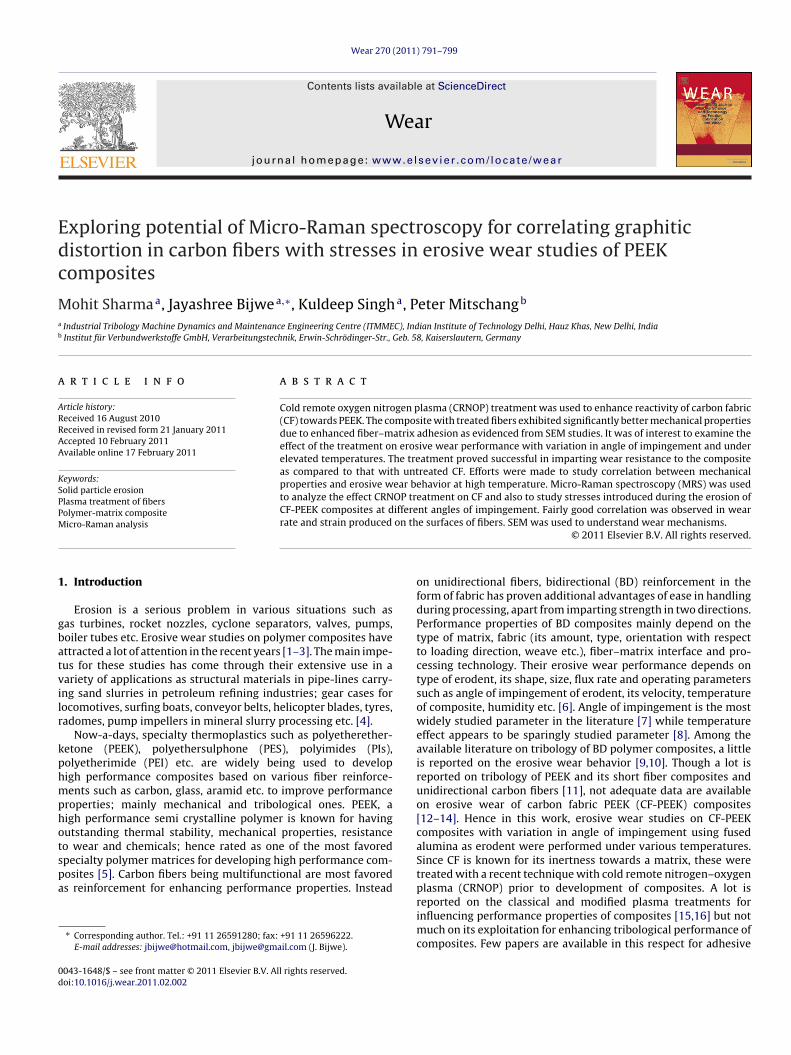
Edc
Ma
b
a
ARRAA
KSPPM
1
gbatvilr
kphmphotspa
0d
Wear 270 (2011) 791–799
Contents lists available at ScienceDirect
Wear
journa l homepage: www.e lsev ier .com/ locate /wear
xploring potential of Micro-Raman spectroscopy for correlating graphiticistortion in carbon fibers with stresses in erosive wear studies of PEEKomposites
ohit Sharmaa, Jayashree Bijwea,∗, Kuldeep Singha, Peter Mitschangb
Industrial Tribology Machine Dynamics and Maintenance Engineering Centre (ITMMEC), Indian Institute of Technology Delhi, Hauz Khas, New Delhi, IndiaInstitut für Verbundwerkstoffe GmbH, Verarbeitungstechnik, Erwin-Schrödinger-Str., Geb. 58, Kaiserslautern, Germany
r t i c l e i n f o
rticle history:eceived 16 August 2010eceived in revised form 21 January 2011ccepted 10 February 2011
a b s t r a c t
Cold remote oxygen nitrogen plasma (CRNOP) treatment was used to enhance reactivity of carbon fabric(CF) towards PEEK. The composite with treated fibers exhibited significantly better mechanical propertiesdue to enhanced fiber–matrix adhesion as evidenced from SEM studies. It was of interest to examine theeffect of the treatment on erosive wear performance with variation in angle of impingement and under
vailable online 17 February 2011
eywords:olid particle erosionlasma treatment of fibers
elevated temperatures. The treatment proved successful in imparting wear resistance to the compositeas compared to that with untreated CF. Efforts were made to study correlation between mechanicalproperties and erosive wear behavior at high temperature. Micro-Raman spectroscopy (MRS) was usedto analyze the effect CRNOP treatment on CF and also to study stresses introduced during the erosion ofCF-PEEK composites at different angles of impingement. Fairly good correlation was observed in wear
on th
olymer-matrix compositeicro-Raman analysis rate and strain produced. Introduction
Erosion is a serious problem in various situations such asas turbines, rocket nozzles, cyclone separators, valves, pumps,oiler tubes etc. Erosive wear studies on polymer composites havettracted a lot of attention in the recent years [1–3]. The main impe-us for these studies has come through their extensive use in aariety of applications as structural materials in pipe-lines carry-ng sand slurries in petroleum refining industries; gear cases forocomotives, surfing boats, conveyor belts, helicopter blades, tyres,adomes, pump impellers in mineral slurry processing etc. [4].
Now-a-days, specialty thermoplastics such as polyetherether-etone (PEEK), polyethersulphone (PES), polyimides (PIs),olyetherimide (PEI) etc. are widely being used to developigh performance composites based on various fiber reinforce-ents such as carbon, glass, aramid etc. to improve performance
roperties; mainly mechanical and tribological ones. PEEK, aigh performance semi crystalline polymer is known for havingutstanding thermal stability, mechanical properties, resistance
o wear and chemicals; hence rated as one of the most favoredpecialty polymer matrices for developing high performance com-osites [5]. Carbon fibers being multifunctional are most favoreds reinforcement for enhancing performance properties. Instead∗ Corresponding author. Tel.: +91 11 26591280; fax: +91 11 26596222.E-mail addresses: [email protected], [email protected] (J. Bijwe).
043-1648/$ – see front matter © 2011 Elsevier B.V. All rights reserved.oi:10.1016/j.wear.2011.02.002
e surfaces of fibers. SEM was used to understand wear mechanisms.© 2011 Elsevier B.V. All rights reserved.
on unidirectional fibers, bidirectional (BD) reinforcement in theform of fabric has proven additional advantages of ease in handlingduring processing, apart from imparting strength in two directions.Performance properties of BD composites mainly depend on thetype of matrix, fabric (its amount, type, orientation with respectto loading direction, weave etc.), fiber–matrix interface and pro-cessing technology. Their erosive wear performance depends ontype of erodent, its shape, size, flux rate and operating parameterssuch as angle of impingement of erodent, its velocity, temperatureof composite, humidity etc. [6]. Angle of impingement is the mostwidely studied parameter in the literature [7] while temperatureeffect appears to be sparingly studied parameter [8]. Among theavailable literature on tribology of BD polymer composites, a littleis reported on the erosive wear behavior [9,10]. Though a lot isreported on tribology of PEEK and its short fiber composites andunidirectional carbon fibers [11], not adequate data are availableon erosive wear of carbon fabric PEEK (CF-PEEK) composites[12–14]. Hence in this work, erosive wear studies on CF-PEEKcomposites with variation in angle of impingement using fusedalumina as erodent were performed under various temperatures.Since CF is known for its inertness towards a matrix, these weretreated with a recent technique with cold remote nitrogen–oxygen
plasma (CRNOP) prior to development of composites. A lot isreported on the classical and modified plasma treatments forinfluencing performance properties of composites [15,16] but notmuch on its exploitation for enhancing tribological performance ofcomposites. Few papers are available in this respect for adhesive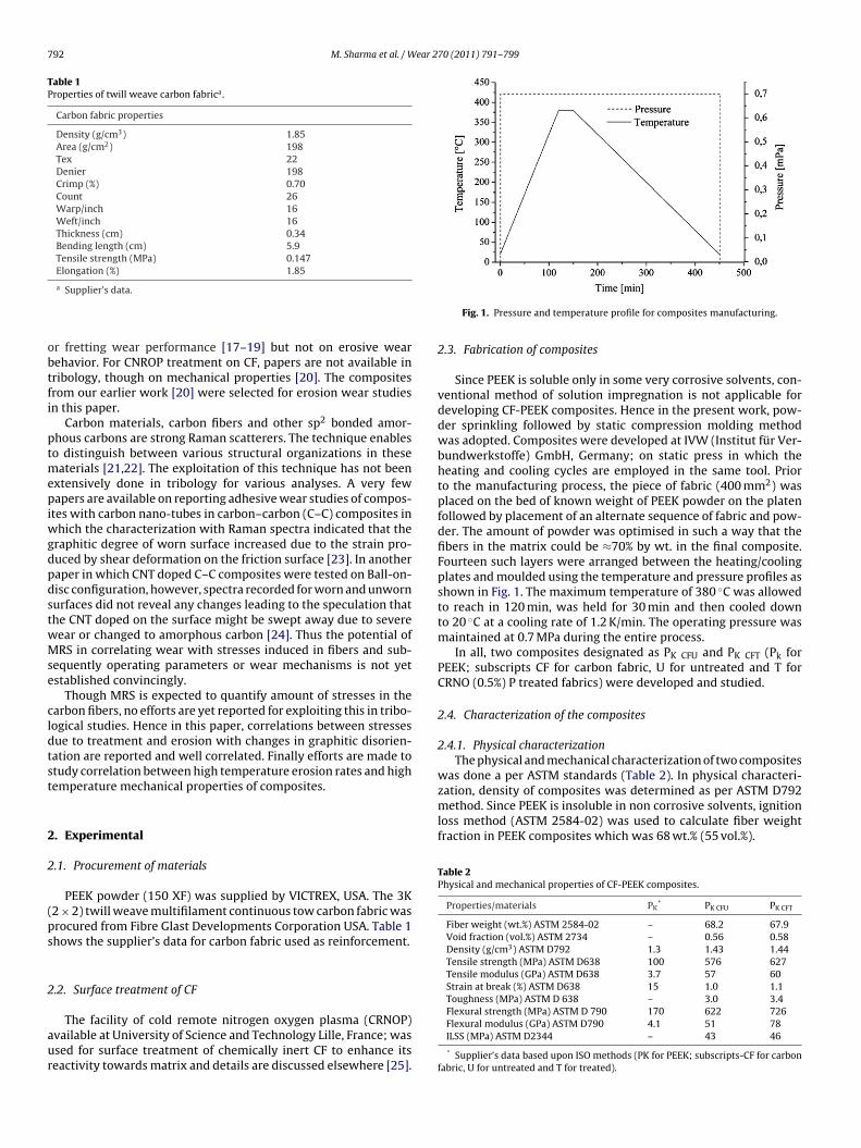
792 M. Sharma et al. / Wear 270 (2011) 791–799
Table 1Properties of twill weave carbon fabrica.
Carbon fabric properties
Density (g/cm3) 1.85Area (g/cm2) 198Tex 22Denier 198Crimp (%) 0.70Count 26Warp/inch 16Weft/inch 16Thickness (cm) 0.34Bending length (cm) 5.9Tensile strength (MPa) 0.147
obtfi
ptmepiwgdpdstwMse
cldtst
2
2
(ps
2
aur
zation, density of composites was determined as per ASTM D792method. Since PEEK is insoluble in non corrosive solvents, ignitionloss method (ASTM 2584-02) was used to calculate fiber weightfraction in PEEK composites which was 68 wt.% (55 vol.%).
Table 2Physical and mechanical properties of CF-PEEK composites.
Properties/materials PK* PK CFU PK CFT
Fiber weight (wt.%) ASTM 2584-02 – 68.2 67.9Void fraction (vol.%) ASTM 2734 – 0.56 0.58Density (g/cm3) ASTM D792 1.3 1.43 1.44Tensile strength (MPa) ASTM D638 100 576 627Tensile modulus (GPa) ASTM D638 3.7 57 60Strain at break (%) ASTM D638 15 1.0 1.1Toughness (MPa) ASTM D 638 – 3.0 3.4Flexural strength (MPa) ASTM D 790 170 622 726Flexural modulus (GPa) ASTM D790 4.1 51 78
Elongation (%) 1.85
a Supplier’s data.
r fretting wear performance [17–19] but not on erosive wearehavior. For CNROP treatment on CF, papers are not available inribology, though on mechanical properties [20]. The compositesrom our earlier work [20] were selected for erosion wear studiesn this paper.
Carbon materials, carbon fibers and other sp2 bonded amor-hous carbons are strong Raman scatterers. The technique enableso distinguish between various structural organizations in these
aterials [21,22]. The exploitation of this technique has not beenxtensively done in tribology for various analyses. A very fewapers are available on reporting adhesive wear studies of compos-
tes with carbon nano-tubes in carbon–carbon (C–C) composites inhich the characterization with Raman spectra indicated that the
raphitic degree of worn surface increased due to the strain pro-uced by shear deformation on the friction surface [23]. In anotheraper in which CNT doped C–C composites were tested on Ball-on-isc configuration, however, spectra recorded for worn and unwornurfaces did not reveal any changes leading to the speculation thathe CNT doped on the surface might be swept away due to severeear or changed to amorphous carbon [24]. Thus the potential ofRS in correlating wear with stresses induced in fibers and sub-
equently operating parameters or wear mechanisms is not yetstablished convincingly.
Though MRS is expected to quantify amount of stresses in thearbon fibers, no efforts are yet reported for exploiting this in tribo-ogical studies. Hence in this paper, correlations between stressesue to treatment and erosion with changes in graphitic disorien-ation are reported and well correlated. Finally efforts are made totudy correlation between high temperature erosion rates and highemperature mechanical properties of composites.
. Experimental
.1. Procurement of materials
PEEK powder (150 XF) was supplied by VICTREX, USA. The 3K2 × 2) twill weave multifilament continuous tow carbon fabric wasrocured from Fibre Glast Developments Corporation USA. Table 1hows the supplier’s data for carbon fabric used as reinforcement.
.2. Surface treatment of CF
The facility of cold remote nitrogen oxygen plasma (CRNOP)
vailable at University of Science and Technology Lille, France; wassed for surface treatment of chemically inert CF to enhance itseactivity towards matrix and details are discussed elsewhere [25].Fig. 1. Pressure and temperature profile for composites manufacturing.
2.3. Fabrication of composites
Since PEEK is soluble only in some very corrosive solvents, con-ventional method of solution impregnation is not applicable fordeveloping CF-PEEK composites. Hence in the present work, pow-der sprinkling followed by static compression molding methodwas adopted. Composites were developed at IVW (Institut für Ver-bundwerkstoffe) GmbH, Germany; on static press in which theheating and cooling cycles are employed in the same tool. Priorto the manufacturing process, the piece of fabric (400 mm2) wasplaced on the bed of known weight of PEEK powder on the platenfollowed by placement of an alternate sequence of fabric and pow-der. The amount of powder was optimised in such a way that thefibers in the matrix could be ≈70% by wt. in the final composite.Fourteen such layers were arranged between the heating/coolingplates and moulded using the temperature and pressure profiles asshown in Fig. 1. The maximum temperature of 380 ◦C was allowedto reach in 120 min, was held for 30 min and then cooled downto 20 ◦C at a cooling rate of 1.2 K/min. The operating pressure wasmaintained at 0.7 MPa during the entire process.
In all, two composites designated as PK CFU and PK CFT (Pk forPEEK; subscripts CF for carbon fabric, U for untreated and T forCRNO (0.5%) P treated fabrics) were developed and studied.
2.4. Characterization of the composites
2.4.1. Physical characterizationThe physical and mechanical characterization of two composites
was done a per ASTM standards (Table 2). In physical characteri-
ILSS (MPa) ASTM D2344 – 43 46
* Supplier’s data based upon ISO methods (PK for PEEK; subscripts-CF for carbonfabric, U for untreated and T for treated).
M. Sharma et al. / Wear 270 (2011) 791–799 793
m
V
wmfr
2
lewpDtt
2
tdpapcbsoa3v
TE
50 100 150 200
300
400
500
600
700
Ten
sile S
tren
gth
(M
Pa)
PK CFU
PK CFT
Fig. 2. Sketch of Erosive wear test rig.
Void contents in composites were calculated using ASTM 2734ethod based on following equation.
oid content (vol.) = 1 − �c
(Wm
�m+ Wf
�f
)(1)
here �c, �m and �f are density of composite (experimental),atrix and fiber (as per supplier’s data), Wm and Wf are weight
raction of matrix and fiber. It was observed that void % was in theange of 0.55 vol.%, which confirms the void free composites.
.4.2. Mechanical propertiesThe composites were evaluated for tensile, flexural and inter-
aminar shear strength (ILSS) properties. Tensile properties werevaluated as per ASTM D638 on Instron universal testing machineith high temperature chamber facility while flexural and ILSSroperties were performed on Lloyd LR-100K machine as per ASTM790 and ASTM D2344 standards respectively. Five samples were
ested for each type of test and average of best three was taken ino consideration.
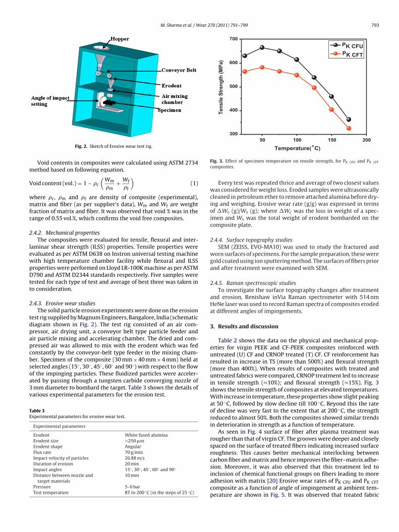
.4.3. Erosive wear studiesThe solid particle erosion experiments were done on the erosion
est rig supplied by Magnum Engineers, Bangalore, India (schematiciagram shown in Fig. 2). The test rig consisted of an air com-ressor, air drying unit, a conveyor belt type particle feeder andir particle mixing and accelerating chamber. The dried and com-ressed air was allowed to mix with the erodent which was fedonstantly by the conveyor-belt type feeder in the mixing cham-er. Specimen of the composite (30 mm × 40 mm × 4 mm) held at
◦ ◦ ◦ ◦ ◦
elected angles (15 , 30 , 45 , 60 and 90 ) with respect to the flowf the impinging particles. These fluidized particles were acceler-ted by passing through a tungsten carbide converging nozzle ofmm diameter to bombard the target. Table 3 shows the details ofarious experimental parameters for the erosion test.able 3xperimental parameters for erosive wear test.
Experimental parameters
Erodent White fused aluminaErodent size ≈250 �mErodent shape AngularFlux rate 70 g/minImpact velocity of particles 26.88 m/sDuration of erosion 20 minImpact angles 15◦ , 30◦ , 45◦ , 60◦ and 90◦
Distance between nozzle andtarget materials
10 mm
Pressure 5–6 barTest temperature RT to 200 ◦C (in the steps of 25 ◦C)
Temperature(°C)
Fig. 3. Effect of specimen temperature on tensile strength, for PK CFU and PK CFT
composites.
Every test was repeated thrice and average of two closest valueswas considered for weight loss. Eroded samples were ultrasonicallycleaned in petroleum ether to remove attached alumina before dry-ing and weighing. Erosive wear rate (g/g) was expressed in termsof �Wc (g)/Ws (g); where �Wc was the loss in weight of a spec-imen and Ws was the total weight of erodent bombarded on thecomposite plate.
2.4.4. Surface topography studiesSEM (ZEISS, EVO-MA10) was used to study the fractured and
worn surfaces of specimens. For the sample preparation, these weregold coated using ion sputtering method. The surfaces of fibers priorand after treatment were examined with SEM.
2.4.5. Raman spectroscopic studiesTo investigate the surface topography changes after treatment
and erosion, Renishaw inVia Raman spectrometer with 514 nmHeNe laser was used to record Raman spectra of composites erodedat different angles of impingements.
3. Results and discussion
Table 2 shows the data on the physical and mechanical prop-erties for virgin PEEK and CF-PEEK composites reinforced withuntreated (U) CF and CRNOP treated (T) CF. CF reinforcement hasresulted in increase in TS (more than 500%) and flexural strength(more than 400%). When results of composites with treated anduntreated fabrics were compared, CRNOP treatment led to increasein tensile strength (≈10%); and flexural strength (≈15%). Fig. 3shows the tensile strength of composites at elevated temperatures.With increase in temperature, these properties show slight peakingat 50 ◦C, followed by slow decline till 100 ◦C. Beyond this the rateof decline was very fast to the extent that at 200 ◦C, the strengthreduced to almost 50%. Both the composites showed similar trendsin deterioration in strength as a function of temperature.
As seen in Fig. 4 surface of fiber after plasma treatment wasrougher than that of virgin CF. The grooves were deeper and closelyspaced on the surface of treated fibers indicating increased surfaceroughness. This causes better mechanical interlocking betweencarbon fiber and matrix and hence improves the fiber–matrix adhe-
sion. Moreover, it was also observed that this treatment led toinclusion of chemical functional groups on fibers leading to moreadhesion with matrix [20] Erosive wear rates of PK CFU and PK CFTcomposite as a function of angle of impingement at ambient tem-perature are shown in Fig. 5. It was observed that treated fabric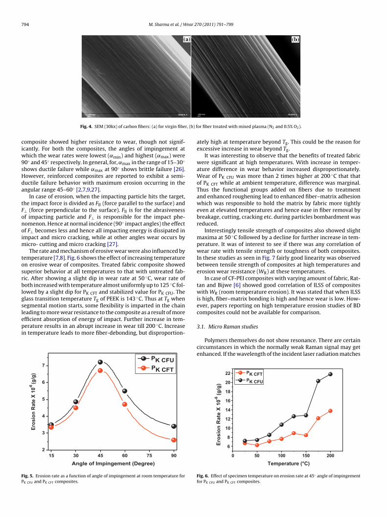
794 M. Sharma et al. / Wear 270 (2011) 791–799
r, (b) f
ciw9sHda
tFonoim
tosrblgslepi
FP
Fig. 4. SEM (30kx) of carbon fibers: (a) for virgin fibe
omposite showed higher resistance to wear, though not signif-cantly. For both the composites, the angles of impingement at
hich the wear rates were lowest (˛min) and highest (˛max) were0◦ and 45◦ respectively. In general, for, ˛max in the range of 15–30◦
hows ductile failure while ˛max at 90◦ shows brittle failure [26].owever, reinforced composites are reported to exhibit a semi-uctile failure behavior with maximum erosion occurring in thengular range 45–60◦ [2,7,9,27].
In case of erosion, when the impacting particle hits the target,he impact force is divided as FII (force parallel to the surface) and⊥ (force perpendicular to the surface). FII is for the abrasivenessf impacting particle and F⊥ is responsible for the impact phe-omenon. Hence at normal incidence (90◦ impact angles) the effectf F⊥ becomes less and hence all impacting energy is dissipated inmpact and micro cracking, while at other angles wear occurs by
icro- cutting and micro cracking [27].The rate and mechanism of erosive wear were also influenced by
emperature [7,8]. Fig. 6 shows the effect of increasing temperaturen erosive wear of composites. Treated fabric composite showeduperior behavior at all temperatures to that with untreated fab-ic. After showing a slight dip in wear rate at 50 ◦C, wear rate ofoth increased with temperature almost uniformly up to 125 ◦C fol-
owed by a slight dip for PK CFT and stabilized value for PK CFU. Thelass transition temperature Tg of PEEK is 143 ◦C. Thus at Tg whenegmental motion starts, some flexibility is imparted in the chain
eading to more wear resistance to the composite as a result of morefficient absorption of energy of impact. Further increase in tem-erature results in an abrupt increase in wear till 200 ◦C. Increasen temperature leads to more fiber-debonding, but disproportion-
15 30 45 60 75 90
2
3
4
5
6
7
Ero
sio
n R
ate
X 1
0-6(g
/g)
Angle of Impingement (Degree)
PK CFU
PK CFT
ig. 5. Erosion rate as a function of angle of impingement at room temperature forK CFU and PK CFT composites.
or fiber treated with mixed plasma (N2 and 0.5% O2).
ately high at temperature beyond Tg. This could be the reason forexcessive increase in wear beyond Tg.
It was interesting to observe that the benefits of treated fabricwere significant at high temperatures. With increase in temper-ature difference in wear behavior increased disproportionately.Wear of PK CFU was more than 2 times higher at 200 ◦C that thatof PK CFT while at ambient temperature, difference was marginal.Thus the functional groups added on fibers due to treatmentand enhanced roughening lead to enhanced fiber–matrix adhesionwhich was responsible to hold the matrix by fabric more tightlyeven at elevated temperatures and hence ease in fiber removal bybreakage, cutting, cracking etc. during particles bombardment wasreduced.
Interestingly tensile strength of composites also showed slightmaxima at 50 ◦C followed by a decline for further increase in tem-perature. It was of interest to see if there was any correlation ofwear rate with tensile strength or toughness of both composites.In these studies as seen in Fig. 7 fairly good linearity was observedbetween tensile strength of composites at high temperatures anderosion wear resistance (WR) at these temperatures.
In case of CF-PEI composites with varying amount of fabric, Rat-tan and Bijwe [6] showed good correlation of ILSS of compositeswith WR (room temperature erosion). It was stated that when ILSSis high, fiber–matrix bonding is high and hence wear is low. How-ever, papers reporting on high temperature erosion studies of BDcomposites could not be available for comparison.
3.1. Micro Raman studies
Polymers themselves do not show resonance. There are certaincircumstances in which the normally weak Raman signal may getenhanced. If the wavelength of the incident laser radiation matches
0 50 100 150 200
6
8
10
12
14
16
18
20
22
Ero
sio
n R
ate
X 1
0-6
(g/g
)
Temperature (°C)
PK CFT
PK CFU
Fig. 6. Effect of specimen temperature on erosion rate at 45◦ angle of impingementfor PK CFU and PK CFT composites.
M. Sharma et al. / Wear 270 (2011) 791–799 795
300
400
500
600
700
5 10 15 20
Ten
sile
Str
engt
h (M
Pa)
Erosion Rate x 10 -6 (g/g)
PK CFT
PK CFU1
23
4
5
6
7
1
2
4
5
6
7
31- RT2- 500C3- 750C4- 1000C5- 1250C6- 1500C7- 1750C
Ft
tiRstp
ptafmf
era11Ddci
fiutcoacctfic[tdi
Ptsedt
1200 1300 1400 1500 1600
(In
ten
sit
y)
Arb
itra
ry U
nit
Raman shift (cm-1)
PK CFU
PK CFT
(a)
1200 1300 1400 1500 1600 1700
(In
ten
sit
y)
Arb
itra
ry U
nit
s
Raman Shift (cm-1
)
PK CFU
PK CFT
(b)
1200 1400 1600
Inte
ns
ity
(A
rbit
rary
Un
it)
Raman Shift (cm-1
)
PK CFU
PK CFT
(c)
ig. 7. Correlation studies on tensile strength and erosive wear rates at variousemperatures.
he intense electronic absorption band then the Raman scatter-ng may be enhanced by several orders of magnitude. In that case,aman process combines with the optical absorption to an excitedtate. The sp2 carbon system is well capable to show this effect dueo electron–phonon interaction; which is least probable in case ofolymers [28].
For most of polymer composites, especially based on thermo-lastics matrix system; there is a large intensity difference betweenhe Raman peaks for reinforcement and the polymer. The spectrarise from polymers hence suppressed under the spectra of rein-orcement (CF); which generates high number of counts. Hence, in
ost of the cases polymers do not show any spectra in compositeorm with carbon based materials [29].
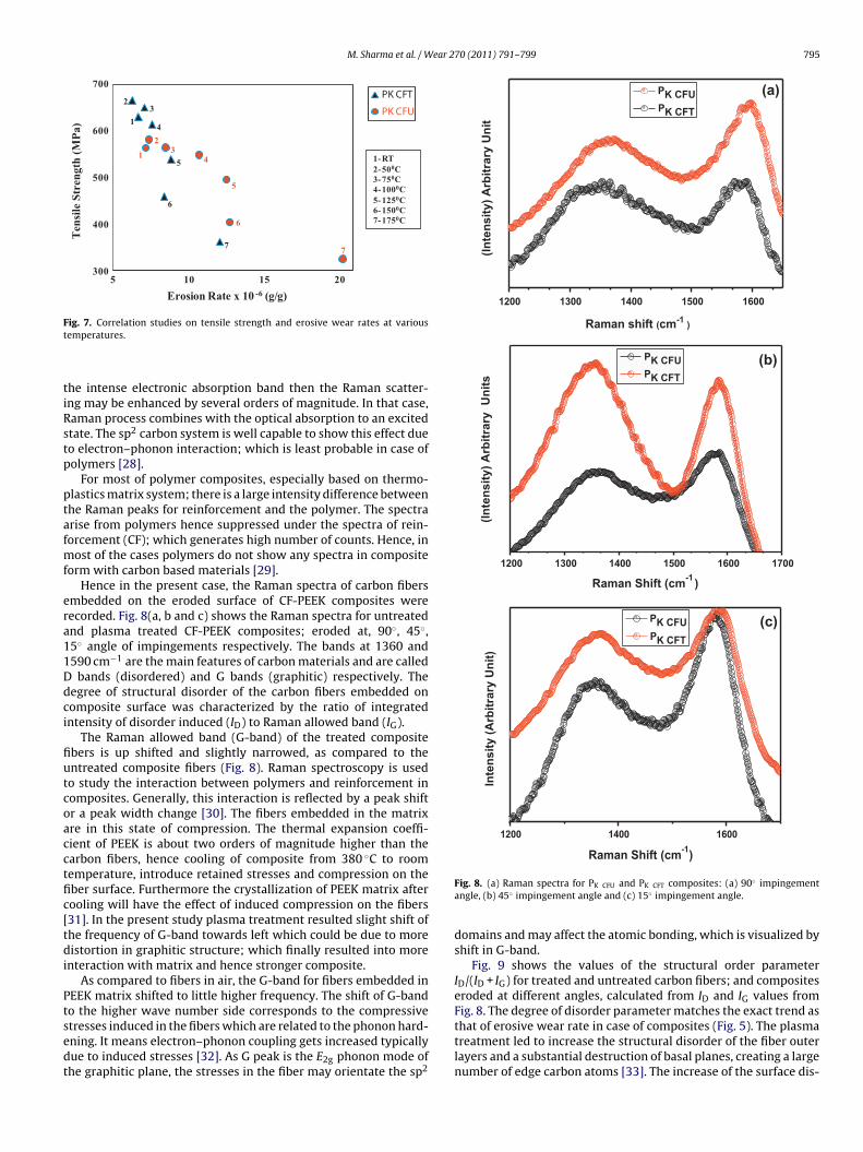
Hence in the present case, the Raman spectra of carbon fibersmbedded on the eroded surface of CF-PEEK composites wereecorded. Fig. 8(a, b and c) shows the Raman spectra for untreatednd plasma treated CF-PEEK composites; eroded at, 90◦, 45◦,5◦ angle of impingements respectively. The bands at 1360 and590 cm−1 are the main features of carbon materials and are called
bands (disordered) and G bands (graphitic) respectively. Theegree of structural disorder of the carbon fibers embedded onomposite surface was characterized by the ratio of integratedntensity of disorder induced (ID) to Raman allowed band (IG).
The Raman allowed band (G-band) of the treated compositebers is up shifted and slightly narrowed, as compared to thentreated composite fibers (Fig. 8). Raman spectroscopy is usedo study the interaction between polymers and reinforcement inomposites. Generally, this interaction is reflected by a peak shiftr a peak width change [30]. The fibers embedded in the matrixre in this state of compression. The thermal expansion coeffi-ient of PEEK is about two orders of magnitude higher than thearbon fibers, hence cooling of composite from 380 ◦C to roomemperature, introduce retained stresses and compression on theber surface. Furthermore the crystallization of PEEK matrix afterooling will have the effect of induced compression on the fibers31]. In the present study plasma treatment resulted slight shift ofhe frequency of G-band towards left which could be due to moreistortion in graphitic structure; which finally resulted into more
nteraction with matrix and hence stronger composite.As compared to fibers in air, the G-band for fibers embedded in
EEK matrix shifted to little higher frequency. The shift of G-bando the higher wave number side corresponds to the compressive
tresses induced in the fibers which are related to the phonon hard-ning. It means electron–phonon coupling gets increased typicallyue to induced stresses [32]. As G peak is the E2g phonon mode ofhe graphitic plane, the stresses in the fiber may orientate the sp2Fig. 8. (a) Raman spectra for PK CFU and PK CFT composites: (a) 90◦ impingementangle, (b) 45◦ impingement angle and (c) 15◦ impingement angle.
domains and may affect the atomic bonding, which is visualized byshift in G-band.
Fig. 9 shows the values of the structural order parameterID/(ID + IG) for treated and untreated carbon fibers; and compositeseroded at different angles, calculated from ID and IG values fromFig. 8. The degree of disorder parameter matches the exact trend as
that of erosive wear rate in case of composites (Fig. 5). The plasmatreatment led to increase the structural disorder of the fiber outerlayers and a substantial destruction of basal planes, creating a largenumber of edge carbon atoms [33]. The increase of the surface dis-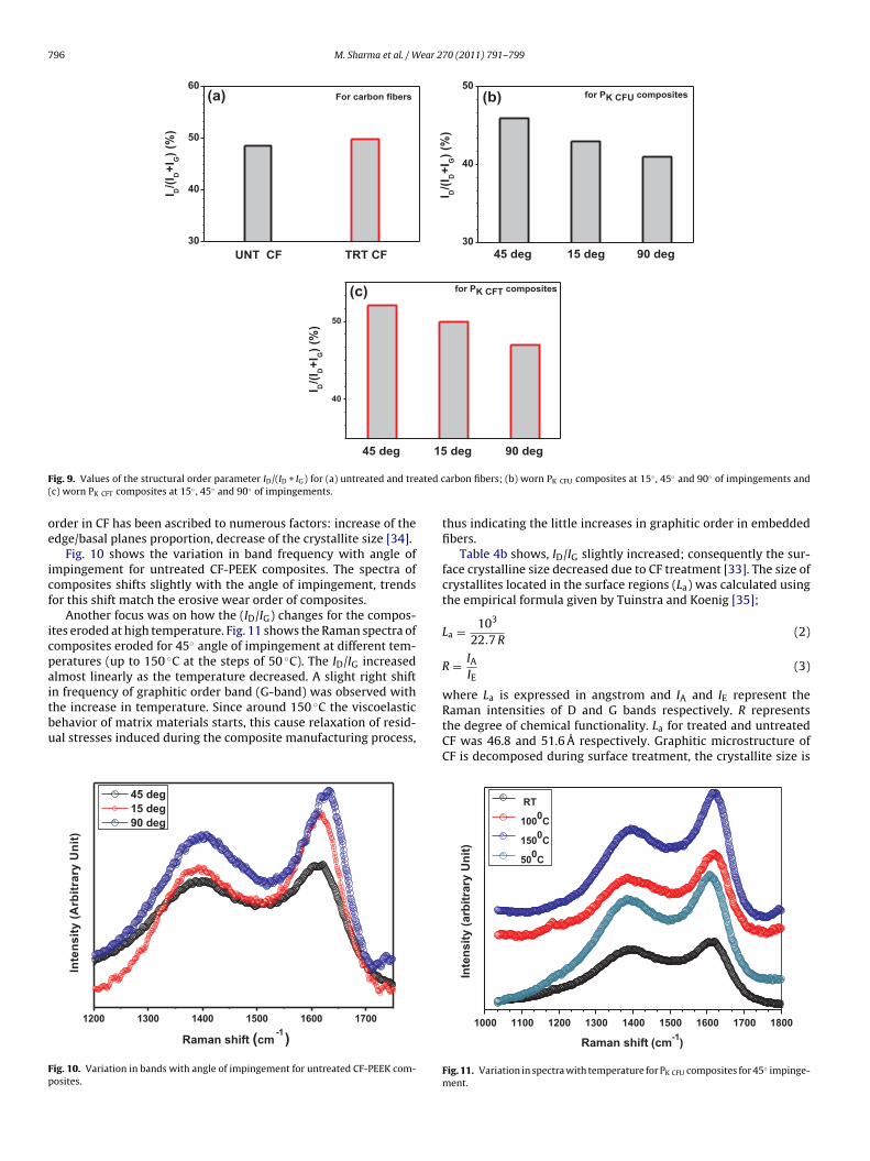
796 M. Sharma et al. / Wear 270 (2011) 791–799
UNT CF TRT CF
30
40
50
60
I D/(
I D+
I G)
(%)
(a) For carbon fibers
45 deg 15 deg 90 deg30
40
50
I D/(
I D+
I G)
(%)
(b) for PK CFU composites
15
40
50I D
/(I D
+I G
) (%
)
(c) for PK CFT composites
F ated c(
oe
icf
icpaitbu
Fp
45 deg
ig. 9. Values of the structural order parameter ID/(ID + IG) for (a) untreated and trec) worn PK CFT composites at 15◦ , 45◦ and 90◦ of impingements.
rder in CF has been ascribed to numerous factors: increase of thedge/basal planes proportion, decrease of the crystallite size [34].
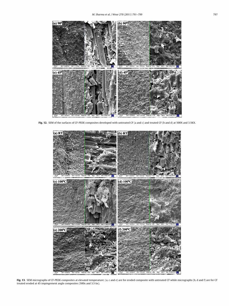
Fig. 10 shows the variation in band frequency with angle ofmpingement for untreated CF-PEEK composites. The spectra ofomposites shifts slightly with the angle of impingement, trendsor this shift match the erosive wear order of composites.
Another focus was on how the (ID/IG) changes for the compos-tes eroded at high temperature. Fig. 11 shows the Raman spectra ofomposites eroded for 45◦ angle of impingement at different tem-eratures (up to 150 ◦C at the steps of 50 ◦C). The ID/IG increasedlmost linearly as the temperature decreased. A slight right shift
n frequency of graphitic order band (G-band) was observed withhe increase in temperature. Since around 150 ◦C the viscoelasticehavior of matrix materials starts, this cause relaxation of resid-al stresses induced during the composite manufacturing process,1200 1300 1400 1500 1600 1700
Raman shift (cm-1
)
45 deg
15 deg
90 deg
Inte
ns
ity
(A
rbit
rary
Un
it)
ig. 10. Variation in bands with angle of impingement for untreated CF-PEEK com-osites.
deg 90 deg
arbon fibers; (b) worn PK CFU composites at 15◦ , 45◦ and 90◦ of impingements and
thus indicating the little increases in graphitic order in embeddedfibers.
Table 4b shows, ID/IG slightly increased; consequently the sur-face crystalline size decreased due to CF treatment [33]. The size ofcrystallites located in the surface regions (La) was calculated usingthe empirical formula given by Tuinstra and Koenig [35];
La = 103
22.7 R(2)
R = IAIE
(3)
where La is expressed in angstrom and IA and IE represent theRaman intensities of D and G bands respectively. R representsthe degree of chemical functionality. La for treated and untreatedCF was 46.8 and 51.6 A respectively. Graphitic microstructure ofCF is decomposed during surface treatment, the crystallite size is
1000 1100 1200 1300 1400 1500 1600 1700 1800
Inte
nsit
y (
arb
itra
ry U
nit
)
Raman shift (cm-1
)
RT
1000C
1500C
500C
Fig. 11. Variation in spectra with temperature for PK CFU composites for 45◦ impinge-ment.
M. Sharma et al. / Wear 270 (2011) 791–799 797
Fig. 12. SEM of the surfaces of CF-PEEK composites developed with untreated CF (a and c) and treated CF (b and d) at 500X and 3.5KX.
Fig. 13. SEM micrographs of CF-PEEK composites at elevated temperature; (a, c and e) are for eroded composite with untreated CF while micrographs (b, d and f) are for CFtreated eroded at 45 impingement angle composites (500x and 3.5 kx).
798 M. Sharma et al. / Wear 2
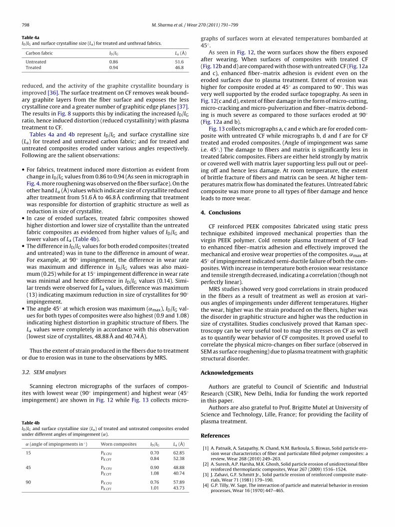
Table 4aID/IG and surface crystalline size (La) for treated and unthread fabrics.
riacTrt
(uF
•
•
•
•
o
3
ii
TIu
Carbon fabric ID/IG La (Å)
Untreated 0.86 51.6Treated 0.94 46.8
educed, and the activity of the graphite crystallite boundary ismproved [36]. The surface treatment on CF removes weak bound-ry graphite layers from the fiber surface and exposes the lessrystalline core and a greater number of graphitic edge planes [37].he results in Fig. 8 supports this by indicating the increased ID/IGatio, hence induced distortion (reduced crystallinity) with plasmareatment to CF.
Tables 4a and 4b represent ID/IG and surface crystalline sizeLa) for treated and untreated carbon fabric; and for treated andntreated composites eroded under various angles respectively.ollowing are the salient observations:
For fabrics, treatment induced more distortion as evident fromchange in ID/IG values from 0.86 to 0.94 (As seen in micrograph inFig. 4. more roughening was observed on the fiber surface). On theother hand La (Å) values which indicate size of crystallite reducedafter treatment from 51.6 A to 46.8 A confirming that treatmentwas responsible for distortion of graphitic structure as well asreduction in size of crystallite.In case of eroded surfaces, treated fabric composites showedhigher distortion and lower size of crystallite than the untreatedfabric composites as evidenced from higher values of ID/IG andlower values of La (Table 4b).The difference in ID/IG values for both eroded composites (treatedand untreated) was in tune to the difference in amount of wear.For example, at 90◦ impingement, the difference in wear ratewas maximum and difference in ID/IG values was also maxi-mum (0.25) while for at 15◦ impingement difference in wear ratewas minimal and hence difference in ID/IG values (0.14). Simi-lar trends were observed for La values, difference was maximum(13) indicating maximum reduction in size of crystallites for 90◦
impingement.The angle 45◦ at which erosion was maximum (˛max), ID/IG val-ues for both types of composites were also highest (0.9 and 1.08)indicating highest distortion in graphitic structure of fibers. TheLa values were completely in accordance with this observation(lowest size of crystallites, 48.88 A and 40.74 A).
Thus the extent of strain produced in the fibers due to treatmentr due to erosion was in tune to the observations by MRS.
.2. SEM analyses
Scanning electron micrographs of the surfaces of compos-tes with lowest wear (90◦ impingement) and highest wear (45◦
mpingement) are shown in Fig. 12 while Fig. 13 collects micro-
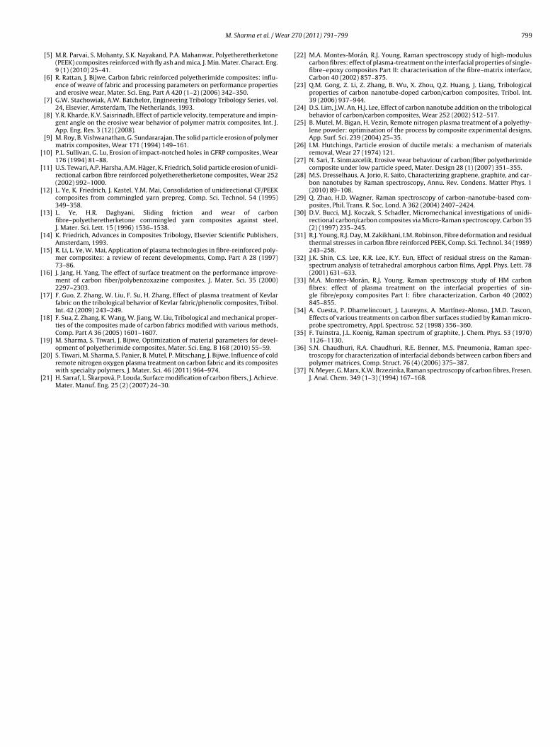
able 4bD/IG and surface crystalline size (La) of treated and untreated composites erodednder different angles of impingement (˛).
˛ (angle of impingements in ◦) Worn composites ID/IG La (Å)
15 PK CFU 0.70 62.85PK CFT 0.84 52.38
45 PK CFU 0.90 48.88PK CFT 1.08 40.74
90 PK CFU 0.76 57.89PK CFT 1.01 43.73
70 (2011) 791–799
graphs of surfaces worn at elevated temperatures bombarded at45◦.
As seen in Fig. 12, the worn surfaces show the fibers exposedafter wearing. When surfaces of composites with treated CF(Fig. 12b and d) are compared with those with untreated CF (Fig. 12aand c), enhanced fiber–matrix adhesion is evident even on theeroded surfaces due to plasma treatment. Extent of erosion washigher for composite eroded at 45◦ as compared to 90◦. This wasvery well supported by the eroded surface topography. As seen inFig. 12(c and d), extent of fiber damage in the form of micro-cutting,micro-cracking and micro-pulverization and fiber–matrix debond-ing is much severe as compared to those surfaces eroded at 90◦
(Fig. 12a and b).Fig. 13 collects micrographs a, c and e which are for eroded com-
posite with untreated CF while micrographs b, d and f are for CFtreated and eroded composites. (Angle of impingement was samei.e. 45◦.) The damage to fibers and matrix is significantly less intreated fabric composites. Fibers are either held strongly by matrixor covered well with matrix layer supporting less pull out or peel-ing off and hence less damage. At room temperature, the extentof brittle fracture of fibers and matrix can be seen. At higher tem-peratures matrix flow has dominated the features. Untreated fabriccomposite was more prone to all types of fiber damage and henceleads to more wear.
4. Conclusions
CF reinforced PEEK composites fabricated using static presstechnique exhibited improved mechanical properties than thevirgin PEEK polymer. Cold remote plasma treatment of CF leadto enhanced fiber–matrix adhesion and effectively improved themechanical and erosive wear properties of the composites. ˛max at45◦ of impingement indicated semi-ductile failure of both the com-posites. With increase in temperature both erosion wear resistanceand tensile strength decreased, indicating a correlation (though notperfectly linear).
MRS studies showed very good correlations in strain producedin the fibers as a result of treatment as well as erosion at vari-ous angles of impingements under different temperatures. Higherthe wear, higher was the strain produced on the fibers, higher wasthe disorder in graphitic structure and higher was the reduction insize of crystallites. Studies conclusively proved that Raman spec-troscopy can be very useful tool to map the stresses on CF as wellas to quantify wear behavior of CF composites. It proved useful tocorrelate the physical micro-changes on fiber surface (observed inSEM as surface roughening) due to plasma treatment with graphiticstructural disorder.
Acknowledgements
Authors are grateful to Council of Scientific and IndustrialResearch (CSIR), New Delhi, India for funding the work reportedin this paper.
Authors are also grateful to Prof. Brigitte Mutel at University ofScience and Technology, Lille, France; for providing the facility ofplasma treatment.
References
[1] A. Patnaik, A. Satapathy, N. Chand, N.M. Barkoula, S. Biswas, Solid particle ero-sion wear characteristics of fiber and particulate filled polymer composites: areview, Wear 268 (2010) 249–263.
[2] A. Suresh, A.P. Harsha, M.K. Ghosh, Solid particle erosion of unidirectional fibrereinforced thermoplastic composites, Wear 267 (2009) 1516–1524.
[3] J. Zahavi, G.F. Schmitt Jr., Solid particle erosion of reinforced composite mate-rials, Wear 71 (1981) 179–190.
[4] G.P. Tilly, W. Sage, The interaction of particle and material behavior in erosionprocesses, Wear 16 (1970) 447–465.
ear 2
[
[
[
[
[
[
[
[
[
[
[
[
[
[
[
[
[
[
[
[
[
[
[
[
[
[1126–1130.
M. Sharma et al. / W
[5] M.R. Parvai, S. Mohanty, S.K. Nayakand, P.A. Mahanwar, Polyetheretherketone(PEEK) composites reinforced with fly ash and mica, J. Min. Mater. Charact. Eng.9 (1) (2010) 25–41.
[6] R. Rattan, J. Bijwe, Carbon fabric reinforced polyetherimide composites: influ-ence of weave of fabric and processing parameters on performance propertiesand erosive wear, Mater. Sci. Eng. Part A 420 (1–2) (2006) 342–350.
[7] G.W. Stachowiak, A.W. Batchelor, Engineering Tribology Tribology Series, vol.24, Elsevier, Amsterdam, The Netherlands, 1993.
[8] Y.R. Kharde, K.V. Saisrinadh, Effect of particle velocity, temperature and impin-gent angle on the erosive wear behavior of polymer matrix composites, Int. J.App. Eng. Res. 3 (12) (2008).
[9] M. Roy, B. Vishwanathan, G. Sundararajan, The solid particle erosion of polymermatrix composites, Wear 171 (1994) 149–161.
10] P.L. Sullivan, G. Lu, Erosion of impact-notched holes in GFRP composites, Wear176 (1994) 81–88.
11] U.S. Tewari, A.P. Harsha, A.M. Häger, K. Friedrich, Solid particle erosion of unidi-rectional carbon fibre reinforced polyetheretherketone composites, Wear 252(2002) 992–1000.
12] L. Ye, K. Friedrich, J. Kastel, Y.M. Mai, Consolidation of unidirectional CF/PEEKcomposites from commingled yarn prepreg, Comp. Sci. Technol. 54 (1995)349–358.
13] L. Ye, H.R. Daghyani, Sliding friction and wear of carbonfibre–polyetheretherketone commingled yarn composites against steel,J. Mater. Sci. Lett. 15 (1996) 1536–1538.
14] K. Friedrich, Advances in Composites Tribology, Elsevier Scientific Publishers,Amsterdam, 1993.
15] R. Li, L. Ye, W. Mai, Application of plasma technologies in fibre-reinforced poly-mer composites: a review of recent developments, Comp. Part A 28 (1997)73–86.
16] J. Jang, H. Yang, The effect of surface treatment on the performance improve-ment of carbon fiber/polybenzoxazine composites, J. Mater. Sci. 35 (2000)2297–2303.
17] F. Guo, Z. Zhang, W. Liu, F. Su, H. Zhang, Effect of plasma treatment of Kevlarfabric on the tribological behavior of Kevlar fabric/phenolic composites, Tribol.Int. 42 (2009) 243–249.
18] F. Sua, Z. Zhang, K. Wang, W. Jiang, W. Liu, Tribological and mechanical proper-ties of the composites made of carbon fabrics modified with various methods,Comp. Part A 36 (2005) 1601–1607.
19] M. Sharma, S. Tiwari, J. Bijwe, Optimization of material parameters for devel-
opment of polyetherimide composites, Mater. Sci. Eng. B 168 (2010) 55–59.20] S. Tiwari, M. Sharma, S. Panier, B. Mutel, P. Mitschang, J. Bijwe, Influence of coldremote nitrogen oxygen plasma treatment on carbon fabric and its compositeswith specialty polymers, J. Mater. Sci. 46 (2011) 964–974.
21] H. Sarraf, L. Skarpová, P. Louda, Surface modification of carbon fibers, J. Achieve.Mater. Manuf. Eng. 25 (2) (2007) 24–30.
[
[
70 (2011) 791–799 799
22] M.A. Montes-Morán, R.J. Young, Raman spectroscopy study of high-moduluscarbon fibres: effect of plasma-treatment on the interfacial properties of single-fibre–epoxy composites Part II: characterisation of the fibre–matrix interface,Carbon 40 (2002) 857–875.
23] Q.M. Gong, Z. Li, Z. Zhang, B. Wu, X. Zhou, Q.Z. Huang, J. Liang, Tribologicalproperties of carbon nanotube-doped carbon/carbon composites, Tribol. Int.39 (2006) 937–944.
24] D.S. Lim, J.W. An, H.J. Lee, Effect of carbon nanotube addition on the tribologicalbehavior of carbon/carbon composites, Wear 252 (2002) 512–517.
25] B. Mutel, M. Bigan, H. Vezin, Remote nitrogen plasma treatment of a polyethy-lene powder: optimisation of the process by composite experimental designs,App. Surf. Sci. 239 (2004) 25–35.
26] I.M. Hutchings, Particle erosion of ductile metals: a mechanism of materialsremoval, Wear 27 (1974) 121.
27] N. Sari, T. Sinmazcelik, Erosive wear behaviour of carbon/fiber polyetherimidecomposite under low particle speed, Mater. Design 28 (1) (2007) 351–355.
28] M.S. Dresselhaus, A. Jorio, R. Saito, Characterizing graphene, graphite, and car-bon nanotubes by Raman spectroscopy, Annu. Rev. Condens. Matter Phys. 1(2010) 89–108.
29] Q. Zhao, H.D. Wagner, Raman spectroscopy of carbon-nanotube-based com-posites, Phil. Trans. R. Soc. Lond. A 362 (2004) 2407–2424.
30] D.V. Bucci, M.J. Koczak, S. Schadler, Micromechanical investigations of unidi-rectional carbon/carbon composites via Micro-Raman spectroscopy, Carbon 35(2) (1997) 235–245.
31] R.J. Young, R.J. Day, M. Zakikhani, I.M. Robinson, Fibre deformation and residualthermal stresses in carbon fibre reinforced PEEK, Comp. Sci. Technol. 34 (1989)243–258.
32] J.K. Shin, C.S. Lee, K.R. Lee, K.Y. Eun, Effect of residual stress on the Raman-spectrum analysis of tetrahedral amorphous carbon films, Appl. Phys. Lett. 78(2001) 631–633.
33] M.A. Montes-Morán, R.J. Young, Raman spectroscopy study of HM carbonfibres: effect of plasma treatment on the interfacial properties of sin-gle fibre/epoxy composites Part I: fibre characterization, Carbon 40 (2002)845–855.
34] A. Cuesta, P. Dhamelincourt, J. Laureyns, A. Martínez-Alonso, J.M.D. Tascon,Effects of various treatments on carbon fiber surfaces studied by Raman micro-probe spectrometry, Appl. Spectrosc. 52 (1998) 356–360.
35] F. Tuinstra, J.L. Koenig, Raman spectrum of graphite, J. Chem. Phys. 53 (1970)
36] S.N. Chaudhuri, R.A. Chaudhuri, R.E. Benner, M.S. Pneumonia, Raman spec-troscopy for characterization of interfacial debonds between carbon fibers andpolymer matrices, Comp. Struct. 76 (4) (2006) 375–387.
37] N. Meyer, G. Marx, K.W. Brzezinka, Raman spectroscopy of carbon fibres, Fresen.J. Anal. Chem. 349 (1–3) (1994) 167–168.
Copyright © 2022 FDOKUMEN