Experimental study of migration of potassium ion through a two-layer soil system
11
List of symbols C Concentration in soil (M L )3 ) C 0 Initial concentration (M L )3 ) D Coefficient of hydrodynamic dispersion (L 2 T )1 ) D e Effective diffusion coefficient (L 2 T )1 ) D md Mechanical dispersion (L 2 T )1 ) D 0 Effective diffusion coefficient in the free-solution (L 2 T )1 ) D 50 Mean grain size (L) J Mass flux into the soil (M L )2 T )1 ) J b Mass flux into the base reservoir (M L )2 T )1 ) H b Thickness of base reservoir (L) H f Height of source solution (L) i Equivalent hydraulic gradient of two-layer soil k Equivalent hydraulic conductivity of two-layer soil (L T )1 ) K f Freundlich sorption parameter K p partition coefficient (L 3 M )1 ) M s Mass of soil (M) n Porosity of soil N Freundlich sorption parameter q Sorbed concentration (M M )1 ) q b , q c Solution collected (L T )1 ) t Time (T) v Seepage velocity (L T )1 ) Yan Jun Du Shigenori Hayashi Song Yu Liu Experimental study of migration of potassium ion through a two-layer soil system Received: 22 February 2005 Accepted: 12 July 2005 Published online: 14 September 2005 ȑ Springer-Verlag 2005 Abstract A barrier system based on the hydraulic trap design concept for a landfill was proposed. To study the field scenario in which a clay liner is underlain by a granular layer func- tioning as a secondary leachate drain layer, a laboratory advection–diffu- sion test was performed to investi- gate factors controlling the transport of contaminants in a two-layer soil system. The soils used for this study were Ariake clay and, the underlying layer, Shirasu soil from the Kyushu region of Japan. Potassium (K + ) was selected as the target chemical species with an initial concentration of 905 mg L )1 . The effective diffu- sion coefficients (D e ) of K + for Ariake clay and Shirasu soil were back-calculated using an available computer program, Pollute V 6.3. Values of D e derived from this experiment are consistent with previously published ones. The Ari- ake clay has lower D e than the Shirasu soil. The hypothesis that mechanical dispersion can be con- sidered negligible is reasonable based on both the observation that the predicted values well fit the experimental data and the analyses of two dimensionless parameters. Parametric analyses show that transport of K + through soils is controlled by advection–diffusion rather than diffusion only, whereas at low Darcy velocity (i.e., £ 10 )9 ms )1 ), transport of K + will be controlled by diffusion. Applica- tions of the test results and para- metric analysis results in practical situations were reviewed. Keywords Advection Clay liner Diffusion Disper- sion Landfill Leachate Japan Environ Geol (2005) 48: 1096–1106 DOI 10.1007/s00254-005-0050-y ORIGINAL ARTICLE Y. J. Du (&) S. Y. Liu Institute of Geotechnical Engineering, Southeast University, Si Pai Lou#2, Nanjing 210096, PR China E-mail: [email protected] S. Hayashi Institute of Lowland Technology, Saga University, Honjo 1, Saga-Shi 840-8502, Japan
Transcript of Experimental study of migration of potassium ion through a two-layer soil system
List of symbols
C Concentration in soil (M L)3)C0 Initial concentration (M L)3)D Coefficient of hydrodynamic dispersion (L2 T)1)De Effective diffusion coefficient (L2 T)1)Dmd Mechanical dispersion (L2 T)1)D0 Effective diffusion coefficient in the free-solution
(L2 T)1)D50 Mean grain size (L)J Mass flux into the soil (M L)2 T)1)Jb Mass flux into the base reservoir (M L)2 T)1)Hb Thickness of base reservoir (L)Hf Height of source solution (L)
i Equivalent hydraulic gradient of two-layer soilk Equivalent hydraulic conductivity of two-layer
soil (L T)1)Kf Freundlich sorption parameterKp partition coefficient (L3 M)1)Ms Mass of soil (M)n Porosity of soilN Freundlich sorption parameterq Sorbed concentration (M M)1)qb,qc
Solution collected (L T)1)
t Time (T)v Seepage velocity (L T)1)
Yan Jun Du
Shigenori Hayashi
Song Yu Liu
Experimental study of migration of potassiumion through a two-layer soil system
Received: 22 February 2005Accepted: 12 July 2005Published online: 14 September 2005� Springer-Verlag 2005
Abstract A barrier system based onthe hydraulic trap design concept fora landfill was proposed. To study thefield scenario in which a clay liner isunderlain by a granular layer func-tioning as a secondary leachate drainlayer, a laboratory advection–diffu-sion test was performed to investi-gate factors controlling the transportof contaminants in a two-layer soilsystem. The soils used for this studywere Ariake clay and, the underlyinglayer, Shirasu soil from the Kyushuregion of Japan. Potassium (K+)was selected as the target chemicalspecies with an initial concentrationof 905 mg L)1. The effective diffu-sion coefficients (De) of K
+ forAriake clay and Shirasu soil wereback-calculated using an availablecomputer program, Pollute V 6.3.Values of De derived from thisexperiment are consistent with
previously published ones. The Ari-ake clay has lower De than theShirasu soil. The hypothesis thatmechanical dispersion can be con-sidered negligible is reasonablebased on both the observation thatthe predicted values well fit theexperimental data and the analysesof two dimensionless parameters.Parametric analyses show thattransport of K+ through soils iscontrolled by advection–diffusionrather than diffusion only, whereasat low Darcy velocity (i.e.,£ 10)9 m s)1), transport of K+ willbe controlled by diffusion. Applica-tions of the test results and para-metric analysis results in practicalsituations were reviewed.
Keywords Advection Æ Clayliner Æ Diffusion Æ Disper-sion Æ Landfill Æ Leachate Æ Japan
Environ Geol (2005) 48: 1096–1106DOI 10.1007/s00254-005-0050-y ORIGINAL ARTICLE
Y. J. Du (&) Æ S. Y. LiuInstitute of Geotechnical Engineering,Southeast University, Si Pai Lou#2,Nanjing 210096, PR ChinaE-mail: [email protected]
S. HayashiInstitute of Lowland Technology, SagaUniversity, Honjo 1, Saga-Shi 840-8502,Japan
va Darcy velocity (L T)1)Vsol Volume of solution (L3)x Distance (L)
Greek
aL Longitudinal dispersivity (L)h Volumetric water contentqd Dry density of the soil (M L)3)sa Apparent tortuosity factor
Introduction
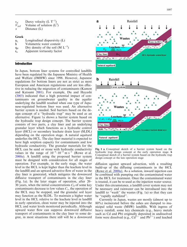
In Japan, bottom liner systems for controlled landfillshave been regulated by the Japanese Ministry of Healthand Welfare (JMHW) since 1998. However, Japaneseregulations for bottom liners are not as strict as mostEuropean and American regulations and are less effec-tive in reducing the migration of contaminants (Kamonand Katsumi 2001). For example, Du and Hayashi(2003) indicated that a high potential impact of con-taminants on groundwater quality in the aquiferunderlying the landfill resulted when one type of Japa-nese-regulated bottom liner was used. An alternativebarrier system is needed. Soil barriers based on the de-sign concept of a ‘‘hydraulic trap’’ may be used as analternative. Figure 1a shows a barrier system based onthe hydraulic trap design concept. The barrier systemconsists of two parts, a clay liner and an underlyinggranular layer which functions as a hydraulic controllayer (HCL) or secondary leachate drain layer (SLDL)depending on the operation stage. A natural aquitardunderlies the HCL. The clay liner material is expected tohave high sorption capacity for contaminants and lowhydraulic conductivity. The granular materials for theHCL can be sand or stone with hydraulic conductivityvalues in the range of 10)3–10)5 m s)1 (Rowe et al.2000a). A landfill using the proposed barrier systemmust be designed with consideration for all stages ofoperation. For example, in the early stage, the waterlevel in the HCL is kept higher than the leachate level inthe landfill and an upward advective flow of water in theclay liner is generated, which mitigates the downwarddiffusive transport of contaminants in the clay liner(Fig. 1a). In the later stages of operation, after 20–30 years, when the initial concentrations C0 of some keycontaminants decrease to low values C1, the operation ofthe HCL may be stopped, and the granular soil layermay function as the SLDL. To maintain a higher waterlevel in the HCL relative to the leachate level in landfillin early operation, clean water may be injected into theHCL and water levels monitored periodically. Althoughupward water flow can suppress downward diffusivetransport of contaminants in the clay liner to some de-gree, in most situations there still will be a downward
diffusion against upward advection, with a resultingbuild-up of the diffusing contaminants in the HCL(Rowe et al. 2000a). As a solution, inward injection canbe combined with pumping out the contaminated waterin the HCL for treatment. Once the contaminated wateris treated, it can be re-used as the injection water source.Under this circumstance, a landfill cover system may notbe necessary and rainwater can be introduced into thelandfill to ‘‘wash’’ the wastes (Fig. 1a) so that they canbe ‘‘rapidly stabilized’’.
Currently in Japan, wastes are mostly (almost up to80%) incinerated before the ashes are dumped to mu-nicipal solid waste (MSW) landfills. With ingress ofheavy rainfall, some key chemicals (e.g., heavy metalssuch as Cd and Pb) originally deposited in undissolvedform were dissolved (e.g., Cd2+ and Pb2+) and leached
Fig. 1 a Conceptual sketch of a barrier system based on thehydraulic trap design concept at the early operation stage. bConceptual sketch of a barrier system based on the hydraulic trapdesign concept at the late operation stage
1097

from the ashes (Shimaoka et al. 1998). Field tests showthat ingress of rainwater would be an effective approachfor significantly enhancing the breakdown of chemicalssuch as Cd, Pb, Ca and Cl to the dissolved state (e.g.,Cd2+, Pb2+, Ca2+ and Cl)) in less than 2 years(Miyawaki et al. 2001). Miyawaki et al. (2001) reportedthat by using an efficient drain system, in less than5 years, concentrations of those dissolved chemicalspecies were reduced to much lower levels. The con-centrations of Cd2+ and Pb2+ were even lower than themaximum permissible value prescribed by the Japanesegovernment. With this evidence, it is reasonable to ex-pect that in the Japanese MSW landfill sites wherewastes are mainly composed of incineration ashes, largeamounts of infiltrating rainwater would promoteleaching of undissolved chemicals in a relatively shorttime. With an efficient PLCS, a substantial mass ofdissolved key contaminants could be leached fromlandfills. After concentrations of contaminants decreaseto relatively low values (C1), the collected leachate maybe discharged to the surrounding environment ifchemical species in the treated leachate satisfy envi-ronmental discharge criteria of the Japanese Govern-ment. The incineration ashes would have been rapidlystabilized at the early operation stage of the proposedbarrier system. It would be difficult to stabilize all ofthe contaminants. Those unstabilized contaminantsmay pose a potential risk to the surrounding environ-ment under certain hydrogeological conditions. Withthe PLCS, the leachate head in landfills can be con-trolled after heavy rainfall. This practice respects andactively utilizes the rainfall climate of Japan to stabilizewastes in a short period, unlike design concepts thatpassively control the infiltration of rainfall in landfillsby the cover systems used in USA (Daniel and Koerner1995) and most European countries (Manassero et al.2000). This type of design would provide highrequirements on the service life of the PLCS and thetreatment techniques of the drained leachate. A failureof the PLCS from clogging of granular drain materialswill substantially weaken the effectiveness of the pro-posed barrier system (Rowe et al. 2000b). Some prac-tical solutions to suppress clogging are discussed byBrune et al. (1991) and Rowe et al. (2000b). Some de-sign parameters, such as the injection and acceptabledifferences between the water level in the HCL andleachate level in landfills, need to be determined. Thistype of design concept for reducing the impacts oflandfill was discussed by Du and Hayashi (2003, 2004).At the late stage, when the function of the HCL isshifted to the SLDL, the cost of maintaining the HCLis expected to drop. Treatment for all leachate collectedby the PLCS and SLDL may not be required, since theconcentrations of some key contaminants in the leach-ate are expected to be relatively low at the early oper-ation stage. Thus expenses for leachate treatment can
be lowered. A landfill cover system can be constructedfor future reuse of landfills as well as for controlling theinfiltration of rainfall.
In the late operation stage, there are situations whenpotentiometric surface in the aquifer is lower than theleachate level in the SLDL (Rowe and Badv 1996).Contaminated water may reach the natural aquitardwith downward advection and downward diffusion ofunstabilized contaminants through both the clay linerand the underlying SLDL. Indeed, as Rowe et al. (1995)indicated, this situation could occur in most of thepractical situations. The groundwater in the aquiferunderlying the natural aquitard may be contaminated.The prediction of the potential impacts involve theunderstanding of the mechanisms that control thetransport of the contaminants in the clay liner and theunderlying SLDL, and determining key parameters suchas effective diffusion coefficients.
A laboratory column test for a two-layer soil system(clay layer and the underlying sand layer) was devised toinvestigate the transport of contaminants and factorscontrolling the transport in the specific soils. A fieldscenario was proposed in which contaminants transportthrough a clay liner and underlying SLDL in landfills.Two soils from Kyushu were selected. A laboratoryadvection–diffusion test was performed to study thetransport of potassium (K+) through the two soils.
Materials description
Two soils, Ariake clay and Shirasu soil, were utilized.Ariake clay is a typical marine sedimentation productaccumulated in the Ariake Bay over the past10,000 years (Ariake Bay Research Group 1965; Oht-subo et al. 1995). The Ariake clay was sampled at adepth of about 70 cm below ground surface at KohokuTown in Saga Prefecture. The Shirasu deposits, whichare widely located in the South Kyushu region of Japan,originate from pyroclastic flows during past volcanicactivity. The Shirasu soil was sampled from Ebi City inMiyazaki Prefecture. Ariake clay was selected for itshigh adsorption capacity (Du et al. 2000). There is also atendency in Japan to build landfill sites in coastal areas(Kamon and Katsumi 2001), and local marine clays likeAriake clay may provide a source for soil barriermaterials. Shirasu soil was used as a SLDL material inthis study. Grain size distribution tests were performedaccording to the JIS A 1204 standard issued by theJapanese Geotechnical Society. Figure 2 and Table 1show the tests results. For the Shirasu soil, the unifor-mity coefficient, Uc, and curvature coefficient, Uc¢, weredetermined from Fig. 2. The Shirasu soil is classified aswell-graded sand (SW) according to the Japanese Uni-fied Soil Classification System. Cation exchange capacity(CEC) was measured using the Schollenberger method
1098
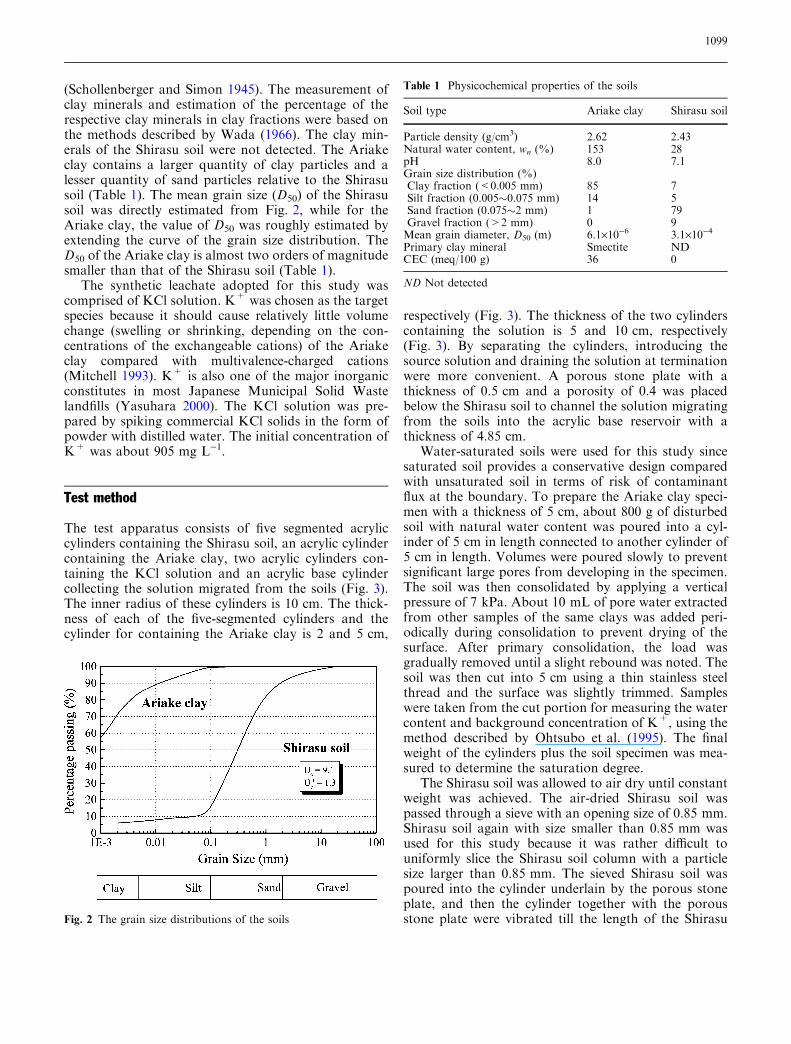
(Schollenberger and Simon 1945). The measurement ofclay minerals and estimation of the percentage of therespective clay minerals in clay fractions were based onthe methods described by Wada (1966). The clay min-erals of the Shirasu soil were not detected. The Ariakeclay contains a larger quantity of clay particles and alesser quantity of sand particles relative to the Shirasusoil (Table 1). The mean grain size (D50) of the Shirasusoil was directly estimated from Fig. 2, while for theAriake clay, the value of D50 was roughly estimated byextending the curve of the grain size distribution. TheD50 of the Ariake clay is almost two orders of magnitudesmaller than that of the Shirasu soil (Table 1).
The synthetic leachate adopted for this study wascomprised of KCl solution. K+ was chosen as the targetspecies because it should cause relatively little volumechange (swelling or shrinking, depending on the con-centrations of the exchangeable cations) of the Ariakeclay compared with multivalence-charged cations(Mitchell 1993). K+ is also one of the major inorganicconstitutes in most Japanese Municipal Solid Wastelandfills (Yasuhara 2000). The KCl solution was pre-pared by spiking commercial KCl solids in the form ofpowder with distilled water. The initial concentration ofK+ was about 905 mg L)1.
Test method
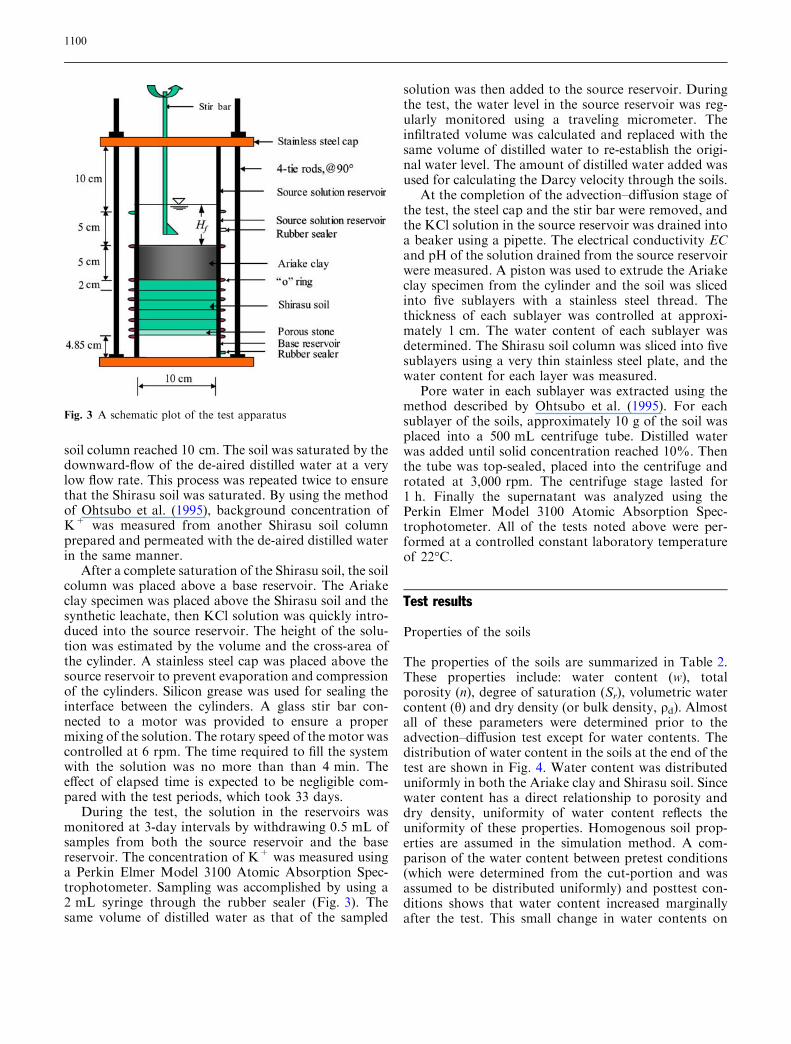
The test apparatus consists of five segmented acryliccylinders containing the Shirasu soil, an acrylic cylindercontaining the Ariake clay, two acrylic cylinders con-taining the KCl solution and an acrylic base cylindercollecting the solution migrated from the soils (Fig. 3).The inner radius of these cylinders is 10 cm. The thick-ness of each of the five-segmented cylinders and thecylinder for containing the Ariake clay is 2 and 5 cm,
respectively (Fig. 3). The thickness of the two cylinderscontaining the solution is 5 and 10 cm, respectively(Fig. 3). By separating the cylinders, introducing thesource solution and draining the solution at terminationwere more convenient. A porous stone plate with athickness of 0.5 cm and a porosity of 0.4 was placedbelow the Shirasu soil to channel the solution migratingfrom the soils into the acrylic base reservoir with athickness of 4.85 cm.
Water-saturated soils were used for this study sincesaturated soil provides a conservative design comparedwith unsaturated soil in terms of risk of contaminantflux at the boundary. To prepare the Ariake clay speci-men with a thickness of 5 cm, about 800 g of disturbedsoil with natural water content was poured into a cyl-inder of 5 cm in length connected to another cylinder of5 cm in length. Volumes were poured slowly to preventsignificant large pores from developing in the specimen.The soil was then consolidated by applying a verticalpressure of 7 kPa. About 10 mL of pore water extractedfrom other samples of the same clays was added peri-odically during consolidation to prevent drying of thesurface. After primary consolidation, the load wasgradually removed until a slight rebound was noted. Thesoil was then cut into 5 cm using a thin stainless steelthread and the surface was slightly trimmed. Sampleswere taken from the cut portion for measuring the watercontent and background concentration of K+, using themethod described by Ohtsubo et al. (1995). The finalweight of the cylinders plus the soil specimen was mea-sured to determine the saturation degree.
The Shirasu soil was allowed to air dry until constantweight was achieved. The air-dried Shirasu soil waspassed through a sieve with an opening size of 0.85 mm.Shirasu soil again with size smaller than 0.85 mm wasused for this study because it was rather difficult touniformly slice the Shirasu soil column with a particlesize larger than 0.85 mm. The sieved Shirasu soil waspoured into the cylinder underlain by the porous stoneplate, and then the cylinder together with the porousstone plate were vibrated till the length of the Shirasu
Table 1 Physicochemical properties of the soils
Soil type Ariake clay Shirasu soil
Particle density (g/cm3) 2.62 2.43Natural water content, wn (%) 153 28pH 8.0 7.1Grain size distribution (%)Clay fraction (<0.005 mm) 85 7Silt fraction (0.005�0.075 mm) 14 5Sand fraction (0.075�2 mm) 1 79Gravel fraction (>2 mm) 0 9Mean grain diameter, D50 (m) 6.1·10)6 3.1·10)4
Primary clay mineral Smectite NDCEC (meq/100 g) 36 0
ND Not detected
Fig. 2 The grain size distributions of the soils
1099
soil column reached 10 cm. The soil was saturated by thedownward-flow of the de-aired distilled water at a verylow flow rate. This process was repeated twice to ensurethat the Shirasu soil was saturated. By using the methodof Ohtsubo et al. (1995), background concentration ofK+ was measured from another Shirasu soil columnprepared and permeated with the de-aired distilled waterin the same manner.
After a complete saturation of the Shirasu soil, the soilcolumn was placed above a base reservoir. The Ariakeclay specimen was placed above the Shirasu soil and thesynthetic leachate, then KCl solution was quickly intro-duced into the source reservoir. The height of the solu-tion was estimated by the volume and the cross-area ofthe cylinder. A stainless steel cap was placed above thesource reservoir to prevent evaporation and compressionof the cylinders. Silicon grease was used for sealing theinterface between the cylinders. A glass stir bar con-nected to a motor was provided to ensure a propermixing of the solution. The rotary speed of the motor wascontrolled at 6 rpm. The time required to fill the systemwith the solution was no more than than 4 min. Theeffect of elapsed time is expected to be negligible com-pared with the test periods, which took 33 days.
During the test, the solution in the reservoirs wasmonitored at 3-day intervals by withdrawing 0.5 mL ofsamples from both the source reservoir and the basereservoir. The concentration of K+ was measured usinga Perkin Elmer Model 3100 Atomic Absorption Spec-trophotometer. Sampling was accomplished by using a2 mL syringe through the rubber sealer (Fig. 3). Thesame volume of distilled water as that of the sampled
solution was then added to the source reservoir. Duringthe test, the water level in the source reservoir was reg-ularly monitored using a traveling micrometer. Theinfiltrated volume was calculated and replaced with thesame volume of distilled water to re-establish the origi-nal water level. The amount of distilled water added wasused for calculating the Darcy velocity through the soils.
At the completion of the advection–diffusion stage ofthe test, the steel cap and the stir bar were removed, andthe KCl solution in the source reservoir was drained intoa beaker using a pipette. The electrical conductivity ECand pH of the solution drained from the source reservoirwere measured. A piston was used to extrude the Ariakeclay specimen from the cylinder and the soil was slicedinto five sublayers with a stainless steel thread. Thethickness of each sublayer was controlled at approxi-mately 1 cm. The water content of each sublayer wasdetermined. The Shirasu soil column was sliced into fivesublayers using a very thin stainless steel plate, and thewater content for each layer was measured.
Pore water in each sublayer was extracted using themethod described by Ohtsubo et al. (1995). For eachsublayer of the soils, approximately 10 g of the soil wasplaced into a 500 mL centrifuge tube. Distilled waterwas added until solid concentration reached 10%. Thenthe tube was top-sealed, placed into the centrifuge androtated at 3,000 rpm. The centrifuge stage lasted for1 h. Finally the supernatant was analyzed using thePerkin Elmer Model 3100 Atomic Absorption Spec-trophotometer. All of the tests noted above were per-formed at a controlled constant laboratory temperatureof 22�C.
Test results
Properties of the soils
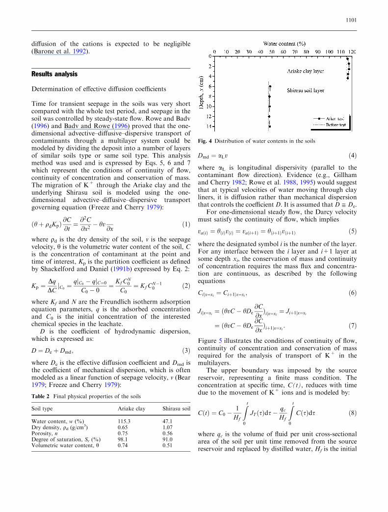
The properties of the soils are summarized in Table 2.These properties include: water content (w), totalporosity (n), degree of saturation (Sr), volumetric watercontent (h) and dry density (or bulk density, qd). Almostall of these parameters were determined prior to theadvection–diffusion test except for water contents. Thedistribution of water content in the soils at the end of thetest are shown in Fig. 4. Water content was distributeduniformly in both the Ariake clay and Shirasu soil. Sincewater content has a direct relationship to porosity anddry density, uniformity of water content reflects theuniformity of these properties. Homogenous soil prop-erties are assumed in the simulation method. A com-parison of the water content between pretest conditions(which were determined from the cut-portion and wasassumed to be distributed uniformly) and posttest con-ditions shows that water content increased marginallyafter the test. This small change in water contents on
Fig. 3 A schematic plot of the test apparatus
1100
diffusion of the cations is expected to be negligible(Barone et al. 1992).
Results analysis
Determination of effective diffusion coefficients
Time for transient seepage in the soils was very shortcompared with the whole test period, and seepage in thesoil was controlled by steady-state flow. Rowe and Badv(1996) and Badv and Rowe (1996) proved that the one-dimensional advective–diffusive–dispersive transport ofcontaminants through a multilayer system could bemodeled by dividing the deposit into a number of layersof similar soils type or same soil type. This analysismethod was used and is expressed by Eqs. 5, 6 and 7which represent the conditions of continuity of flow,continuity of concentration and conservation of mass.The migration of K+ through the Ariake clay and theunderlying Shirasu soil is modeled using the one-dimensional advective–diffusive–dispersive transportgoverning equation (Freeze and Cherry 1979):
ðhþ qdKpÞ@C@t¼ @
2C@x2� hv
@xð1Þ
where qd is the dry density of the soil, v is the seepagevelocity, h is the volumetric water content of the soil, Cis the concentration of contaminant at the point andtime of interest, Kp is the partition coefficient as definedby Shackelford and Daniel (1991b) expressed by Eq. 2:
Kp ¼DqDC C0j ¼ q C0
� q C¼0jjC0 � 0
¼ Kf CN0
C0¼ Kf CN�1
0 ð2Þ
where Kf and N are the Freundlich isotherm adsorptionequation parameters, q is the adsorbed concentrationand C0 is the initial concentration of the interestedchemical species in the leachate.
D is the coefficient of hydrodynamic dispersion,which is expressed as:
D ¼ De þ Dmd; ð3Þ
where De is the effective diffusion coefficient and Dmd isthe coefficient of mechanical dispersion, which is oftenmodeled as a linear function of seepage velocity, v (Bear1979; Freeze and Cherry 1979):
Dmd ¼ aLv ð4Þ
where aL is longitudinal dispersivity (parallel to thecontaminant flow direction). Evidence (e.g., Gillhamand Cherry 1982; Rowe et al. 1988, 1995) would suggestthat at typical velocities of water moving through clayliners, it is diffusion rather than mechanical dispersionthat controls the coefficient D. It is assumed that D @ De.
For one-dimensional steady flow, the Darcy velocitymust satisfy the continuity of flow, which implies
vaðiÞ ¼ hðiÞvðiÞ ¼ vaðiþ1Þ ¼ hðiþ1Þvðiþ1Þ ð5Þ
where the designated symbol i is the number of the layer.For any interface between the i layer and i+1 layer atsome depth xi, the conservation of mass and continuityof concentration requires the mass flux and concentra-tion are continuous, as described by the followingequations
Ci xj ¼xi ¼ Ciþ1 xj ¼xi ; ð6Þ
Ji x¼xij ¼ ðhvC � hDe@C@xÞi x¼xij ¼ Jiþ1 x¼xij
¼ ðhvC � hDe@C@xÞiþ1 x¼xij : ð7Þ
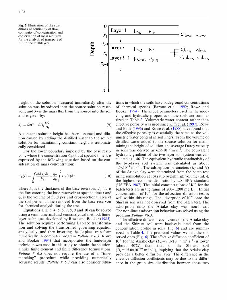
Figure 5 illustrates the conditions of continuity of flow,continuity of concentration and conservation of massrequired for the analysis of transport of K+ in themultilayers.
The upper boundary was imposed by the sourcereservoir, representing a finite mass condition. Theconcentration at specific time, C(t), reduces with timedue to the movement of K+ ions and is modeled by:
CðtÞ ¼ C0 �1
Hf
Z t
0
JT ðsÞds� qc
Hf
Z t
0
CðsÞds ð8Þ
where qc is the volume of fluid per unit cross-sectionalarea of the soil per unit time removed from the sourcereservoir and replaced by distilled water, Hf is the initial
Table 2 Final physical properties of the soils
Soil type Ariake clay Shirasu soil
Water content, w (%) 115.3 47.1Dry density, qd (g/cm3) 0.65 1.07Porosity, n 0.75 0.56Degree of saturation, Sr (%) 98.1 91.0Volumetric water content, h 0.74 0.51
Fig. 4 Distribution of water contents in the soils
1101
height of the solution measured immediately after thesolution was introduced into the source solution reser-voir, and JT is the mass flux from the source into the soiland is given by:
JT ¼ hvC � hDe@C@x
: ð9Þ
A constant solution height has been assumed and dilu-tion caused by adding the distilled water to the sourcesolution for maintaining constant height is automati-cally considered.
For the lower boundary imposed by the base reser-voir, where the concentration Cb(t), at specific time t, isexpressed by the following equation based on the con-sideration of mass concentration:
CbðtÞ ¼Z t
0
JbðsÞdshb
� qb
hb
Z t
0
CbðsÞds ð10Þ
where hb is the thickness of the base reservoir, Jb (t) isthe flux entering the base reservoir at specific time t andqb is the volume of fluid per unit cross-sectional area ofthe soil per unit time removed from the base reservoirfor chemical analysis during the test.
Equations 1, 2, 3, 4, 5, 6, 7, 8, 9 and 10 can be solvedusing a seminumerical and semianalytical method, finite-layer technique, developed by Rowe and Booker (1985).The solution requires performing Laplace transforma-tion and solving the transformed governing equationanalytically, and then inverting the Laplace transformnumerically. A computer program Pollute V 6.3 (Roweand Booker 1994) that incorporates the finite-layertechnique was used in this study to obtain the solution.Unlike finite element and finite difference formulations,Pollute V 6.3 does not require the use of a ‘‘time-marching’’ procedure while providing numericallyaccurate results. Pollute V 6.3 can also consider situa-
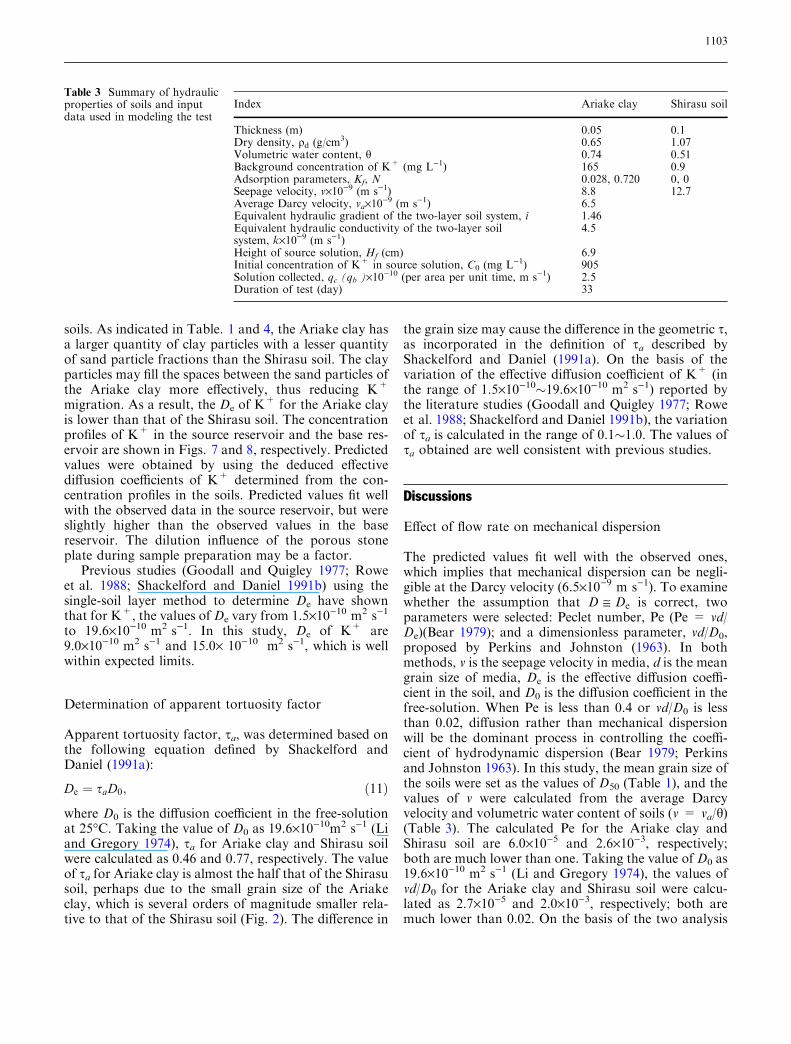
tions in which the soils have background concentrationsof chemical species (Barone et al. 1992; Rowe andBooker 1994). The input parameters used in the mod-eling and hydraulic properties of the soils are summa-rized in Table 3. Volumetric water content rather thaneffective porosity was used since Kim et al. (1997), Roweand Badv (1996) and Rowe et al. (1988) have found thatthe effective porosity is essentially the same as the vol-umetric water content in soil liners. From the volume ofdistilled water added to the source solution for main-taining the height of solution, the average Darcy velocityin soils was derived as 6.5·10)9 m s)1. The equivalenthydraulic gradient of the two-layer soil system was cal-culated as 1.46. The equivalent hydraulic conductivity ofthe two-layer soil system was calculated as about4.5·10)9 m s)1. The adsorption parameters (Kf and N)of the Ariake clay were determined from the batch testusing soil:solution at 1:4 ratio [weight (g): volume (mL)],the highest recommended ratio by US EPA standard(US EPA 1987). The initial concentrations of K+ for thebatch tests are in the range of 200–1,200 mg L)1. Initialconcentration of K+ for the advection–diffusion test iswell within this range. The adsorption of K+ onto theShirasu soil was not observed from the batch test. Theadsorption onto the Ariake clay was non-linear.The non-linear adsorption behavior was solved using theprogram Pollute V6.3.
The effective diffusion coefficients of the Ariake clayand the Shirasu soil were back-calculated from theconcentration profile in soils (Fig. 6) and are summa-rized in Table 4. The predicted values well fit the ob-served ones (Fig. 6). The effective diffusion coefficient ofK+ for the Ariake clay (De=9.0·10)10 m2 s)1) is lower(about 40%) than that of the Shirasu soil(De=15.0·10)10 m2 s)1), implying that the Ariake clayprovides a better diffusion layer. The difference in theeffective diffusion coefficients may be due to the differ-ence in the grain size distribution between these two
Fig. 5 Illustration of the con-ditions of continuity of flow,continuity of concentration andconservation of mass requiredfor the analysis of transport ofK+ in the multilayers
1102
soils. As indicated in Table. 1 and 4, the Ariake clay hasa larger quantity of clay particles with a lesser quantityof sand particle fractions than the Shirasu soil. The clayparticles may fill the spaces between the sand particles ofthe Ariake clay more effectively, thus reducing K+
migration. As a result, the De of K+ for the Ariake clay
is lower than that of the Shirasu soil. The concentrationprofiles of K+ in the source reservoir and the base res-ervoir are shown in Figs. 7 and 8, respectively. Predictedvalues were obtained by using the deduced effectivediffusion coefficients of K+ determined from the con-centration profiles in the soils. Predicted values fit wellwith the observed data in the source reservoir, but wereslightly higher than the observed values in the basereservoir. The dilution influence of the porous stoneplate during sample preparation may be a factor.
Previous studies (Goodall and Quigley 1977; Roweet al. 1988; Shackelford and Daniel 1991b) using thesingle-soil layer method to determine De have shownthat for K+, the values of De vary from 1.5·10)10 m2 s)1
to 19.6·10)10 m2 s)1. In this study, De of K+ are9.0·10)10 m2 s)1 and 15.0· 10)10 m2 s)1, which is wellwithin expected limits.
Determination of apparent tortuosity factor
Apparent tortuosity factor, sa, was determined based onthe following equation defined by Shackelford andDaniel (1991a):
De ¼ saD0; ð11Þ
where D0 is the diffusion coefficient in the free-solutionat 25�C. Taking the value of D0 as 19.6·10)10m2 s)1 (Liand Gregory 1974), sa for Ariake clay and Shirasu soilwere calculated as 0.46 and 0.77, respectively. The valueof sa for Ariake clay is almost the half that of the Shirasusoil, perhaps due to the small grain size of the Ariakeclay, which is several orders of magnitude smaller rela-tive to that of the Shirasu soil (Fig. 2). The difference in
the grain size may cause the difference in the geometric s,as incorporated in the definition of sa described byShackelford and Daniel (1991a). On the basis of thevariation of the effective diffusion coefficient of K+ (inthe range of 1.5·10)10�19.6·10)10 m2 s)1) reported bythe literature studies (Goodall and Quigley 1977; Roweet al. 1988; Shackelford and Daniel 1991b), the variationof sa is calculated in the range of 0.1�1.0. The values ofsa obtained are well consistent with previous studies.
Discussions
Effect of flow rate on mechanical dispersion
The predicted values fit well with the observed ones,which implies that mechanical dispersion can be negli-gible at the Darcy velocity (6.5·10)9 m s)1). To examinewhether the assumption that D @ De is correct, twoparameters were selected: Peclet number, Pe (Pe = vd/De)(Bear 1979); and a dimensionless parameter, vd/D0,proposed by Perkins and Johnston (1963). In bothmethods, v is the seepage velocity in media, d is the meangrain size of media, De is the effective diffusion coeffi-cient in the soil, and D0 is the diffusion coefficient in thefree-solution. When Pe is less than 0.4 or vd/D0 is lessthan 0.02, diffusion rather than mechanical dispersionwill be the dominant process in controlling the coeffi-cient of hydrodynamic dispersion (Bear 1979; Perkinsand Johnston 1963). In this study, the mean grain size ofthe soils were set as the values of D50 (Table 1), and thevalues of v were calculated from the average Darcyvelocity and volumetric water content of soils (v = va/h)(Table 3). The calculated Pe for the Ariake clay andShirasu soil are 6.0·10)5 and 2.6·10)3, respectively;both are much lower than one. Taking the value of D0 as19.6·10)10 m2 s)1 (Li and Gregory 1974), the values ofvd/D0 for the Ariake clay and Shirasu soil were calcu-lated as 2.7·10)5 and 2.0·10)3, respectively; both aremuch lower than 0.02. On the basis of the two analysis
Table 3 Summary of hydraulicproperties of soils and inputdata used in modeling the test
Index Ariake clay Shirasu soil
Thickness (m) 0.05 0.1Dry density, qd (g/cm3) 0.65 1.07Volumetric water content, h 0.74 0.51Background concentration of K+ (mg L)1) 165 0.9Adsorption parameters, Kf, N 0.028, 0.720 0, 0Seepage velocity, v·10)9 (m s)1) 8.8 12.7Average Darcy velocity, va·10)9 (m s)1) 6.5Equivalent hydraulic gradient of the two-layer soil system, i 1.46Equivalent hydraulic conductivity of the two-layer soilsystem, k·10)9 (m s)1)
4.5
Height of source solution, Hf (cm) 6.9Initial concentration of K+ in source solution, C0 (mg L)1) 905Solution collected, qc (qb )·10)10 (per area per unit time, m s)1) 2.5Duration of test (day) 33
1103

results, mechanical dispersion is considered negligible.This finding is consistent with previous works (Gillhamand Cherry 1982; Rowe and Badv 1996) which foundthat at relatively low Darcy velocity, mechanical dis-persion in soil liners can be neglected. Although multi-test results would be more representative, the
experimental results obtained are useful for discussingthe effect of flow rate on mechanical dispersion.
The phenomenon that mechanical dispersion is neg-ligible may be due to the characteristics of the soils (e.g.,homogeneity, grain size). Soil preparation may havecontributed to homogeneous distribution of the flow. Onthe other hand, dispersivity (aL) is largely affected by thegrain size of soil (Bear 1979), and the relatively smallmean grain size of soils may contribute to the negligiblemechanical dispersion. The relatively low Darcy velocity(Eq. 4) results in lower mechanical dispersion.
Effect of flow rate on transport of K+
To determine if only diffusion controlled the transportof K+ in this study, parametric analyses were performedwith variable Darcy velocity. Although it is argued thatboth concentration and mass flux should be consideredas evaluation criteria when dealing with leakage ofcontaminant from soil barriers, other evidence (Roweet al. 1988; Rowe and Badv 1996; Badv and Rowe 1996)have shown that using only variation of concentrationcan achieve a satisfactory result. Variations of concen-tration distribution in the source and base resourceswere selected as evaluation criteria. At the Darcyvelocity va=0, which means the pure diffusion process,the difference between the predicted and observed valuesis noticeable (Fig. 6). It is inferred that the transport ofK+ in the soils was not purely diffusive. Advection aswell as diffusion played roles in controlling the migra-tion of K+ in the soils. At the Darcy velocityva=10)9 m s)1, the predicted value does not signifi-cantly differ from pure diffusion. If the Darcy velocity vais held below this critical value, the migration of K+
through the soils could be controlled by diffusion.Even a small range of Darcy velocity (from 6.5·10)9
to 10)9 m s)1), while other parameters are constant,could cause noticeable change in the concentration ofK+ in the Shirasu soil layer, but less noticeable changein the Ariake clay layer (Fig. 6). This is partly becausethe pathway for moving K+ ions in the Ariake clay isconstricted than in the Shirasu soil caused by the dif-ference in grain size. Figures 7 and 8 show the effect offlow rate on the migration of K+ examined by theconcentration versus time in the source and base reser-voirs, respectively.
Practical implication
In constructing modern MSW landfills, the hydraulicconductivity of clay liners is restricted to low values. Forexample, the US Environmental Protection Agency (USEPA) requires that the hydraulic conductivity of clay
Fig. 6 Effect of flow rate on the transport of K+ in the soils
Fig. 7 Effect of flow rate on the transport of K+ examined by theconcentration versus time in the source reservoir
Fig. 8 Effect of flow rate on the transport of K+ examined by theconcentration versus time in the base reservoir
1104

liners at MSW landfills should be less than 10)9 m s)1.Restricting the low hydraulic conductivity is a beneficialaspect associated with reducing the Darcy velocity,thereby ensuring that diffusion of contaminants in linersis dominant over advection and mechanical dispersion.Field investigations show that in landfills with efficientleachate collection systems, when the hydraulic con-ductivity of the clay liners is controlled at less than10)10 m s)1, the dominant process controlling thetransport of contaminants in the liners would be diffu-sion (Darcy velocity is less than 10)10 m s)1) (King et al.1993).
The two-layer soil system presented has the equiva-lent hydraulic conductivity of 4.5·10)9 m s)1. The testresults indicate that at the Darcy velocity examined(6.5·10)9 m s)1), diffusion as well as advection con-trolled the transport of K+ . The parametric analysisshows that when the Darcy velocity is less than10)9 m s)1, diffusion would be the dominant processcontrolling the transport of K+ in both soils. Therefore,when Ariake clay and underlying sand are used in theproposed barrier system (Fig. 1), if the hydraulic con-ductivity of Ariake clay is controlled to low values,consequently the equivalent hydraulic conductivity ofthe two-layer soil system (Ariake clay liner and theunderlying sand layer) is also controlled to acceptablylow values (e.g., <10)9 m s)1). Diffusion would then bethe dominant process controlling the transport of con-taminants through both soils. Under this condition, theeffective diffusion coefficients and the sorption parame-ters (Kf and N) would provide primary parameters forevaluating potential impact of landfills (Fig. 1b). TheAriake clay liner as well as the SLDL will function asdiffusion barriers to delay downward diffusive transportof contaminants, thereby reducing potential impact oflandfills.
In applying the proposed barrier system, clay withlow hydraulic conductivity should be combined withvarying head difference between the water level in theHCL and the leachate level in landfills at the earlyoperation stage (Fig. 1a). At the same head difference,the lower the hydraulic conductivity of the clay liner, thelower the upward Darcy velocity in the clay liner will be.Too low upward Darcy velocity will not be efficient inreducing the downward diffusive transport of contami-nants. Increasing the head difference is necessary. Inmost practical situations, the hydraulic conductivity ofthe clay liners in landfills could be gradually reducedafter buildup and reduced about 10-fold after only five
years of operation (King et al. 1993). At the earlyoperation stage of the proposed barrier system, it isnecessary to increase the head difference between thewater head in the HCL and the leachate level in thelandfill to compensate for the reduced upward Darcyvelocity in the clay liner caused by consolidation of theoverlying wastes.
Summary and conclusions
A landfill barrier system based on the hydraulic controltrap design concept was proposed. The early and lateoperation stages of the barrier system, where the gran-ular layer functions as the HCL and SLDL, wereexamined. At the late operation stage, when there is adownward advective flow of contaminated waterthrough both the clay liner and the underlying SLDL,there will be potential impacts on underlying aquifers. Alaboratory advection–diffusion test for investigating thefactors controlling the transport of contaminantsthrough a two-layer soil system was devised. Two soilsfrom Kyushu in Japan, the Ariake clay and Shirasu soil,representing the clay liner and the SLDL materials wereused in a controlled test. Results were analyzed using theone-dimensional advective–diffusive–dispersive trans-port theory. Factors controlling the transport of con-taminant through the soils were discussed based on theparametric analyses.
The effective diffusion coefficients of the targetchemical species of K+ for the two soils were back-calculated and were found to be consistent with litera-ture using the single-soil layer method, indicating thatthe proposed testing method is acceptable. Two-layersoil system method may be used as a time and cost-effective method for studying field scenarios where theclay liner is underlain by SLDL in landfills.
The derived effective diffusion coefficient of the Ari-ake clay is lower (about 40%) than that of the Shirasusoil, implying that the Ariake clay provides a betterdiffusion barrier. Different values of De for the two soilsmay be mainly due to the different grain size distribu-tion.
The parametric analyses reveal that under conditionspresented in the study, the transport of K+ in both theAriake clay and Shirasu soil was controlled by advectionas well as diffusion. However, at relatively low Darcyvelocity, diffusion was the dominant process controllingthe transport of K+ in the soils.
Table 4 Summary of thederived effective diffusioncoefficients, apparent tortuosityfactor and some geotechnicalproperties of the soils
Soil type Grain size distribution (%) D50(m) De·10)10 (m2 s)1) sa
Sand Silt Clay
Ariake clay 1 14 85 6.1·10)6 9.0 0.46Shirasu soil 79 5 7 3.1·10)4 15.0 0.77
1105

Mechanical dispersion through the two soils wasfound to be negligible. The predicted values usingadvection–diffusion equation fit well with the experi-mental data. An analysis based on the two dimensionlessparameters shows that mechanical dispersion could benegligible under the conditions presented.
When using Ariake clay and sand in the proposedbarrier system in landfills at early operation stages, if the
design hydraulic conductivity of Ariake clay liner iscontrolled to acceptably low values, at late operationstage, diffusion would dominate the transport of con-taminants in both layers. To guarantee the effectivenessof the proposed barrier system at the early operationstage, it is necessary to increase the head difference be-tween the water level in the HCL and the leachate levelin landfills.
References
Ariake Bay Research Group (1965) Qua-ternary system of the Ariake andShiranui Bay Areas, with special refer-ence to the Ariake soft clay (in Japanesewith English summary), Association forGeological Collaboration in Japan,Saga
Badv K, Rowe RK (1996) Contaminanttransport through a soil liner underlainby an unsaturated stone collection lay-er. Can Geotech J 33(2):416–430
Barone FS, Rowe RK, Quigley RM (1992)A laboratory estimation of chloridediffusion coefficient and tortuosity formudstone. J Geotech Eng ASCE118(7):1031–1046
Bear J (1979) Hydraulics of groundwater.McGraw-Hill, New York
Brune M, Ramke HG, Collins HJ, HanertHH (1991) Incrustation process indrainage systems of landfills. In: Pro-ceedings of the 3rd international landfillsymposium. CISA Publisher, Cagliari,pp 999–1035
Daniel DE, Koerner RM (1995) Wastecontaminant facilities: guidance forconstruction, quality assurance, andquality control of liner and cover sys-tems. ASCE Press, New York
Du YJ, Hayashi S (2003) Evaluation on theperformance of a proposed soil barriersystem in waste disposal sites. In: YuYZ, Akagi H (eds) Geotechnical engi-neering in urban construction. TsinghuaUniversity Press, Beijing, pp 252–259
Du YJ, Hayashi S (2004) Evaluation onperformance of proposed new barriersystem. In: Proceeding of the interna-tional symposium on lowland technol-ogy (ISLT2004). Kasetsart UniversityPress, Bangkok, pp 207–212
Du YJ, Hayashi S, Hino T, Tanaka K(2000) Contaminant adsorption char-acteristics of Kyushu regional soils.Lowland Tech Int 2(2):31–41
Freeze RA, Cherry JA (1979) Groundwa-ter. Prentice-Hall Inc, Englewood Cliffs
Gillham RW, Cherry JA (1982) Contami-nant migration in saturated unconsoli-dated geologic deposits. Special Paper189, Geophysical Society of America,Denver, Colorado, pp 31–62
Goodall DC, Quigley RM (1977) Pollutantmigration from two sanitary landfillsites near Sarnia, Ontario. Can GeotechJ 14(2):223–236
Kamon M, Katsumi T (2001) Clay linersfor waste landfill. In: Adachi K, FukueM (eds) Clay science for engineering.Balkema, Rotterdam, pp 29–46
Kim JY, Edil TB, Park JK (1997) Effectiveporosity and seepage velocity in columntests on compacted clay. J GeotechGeoenviron Eng ASCE 123(12):1135–1142
King KS, Quigley RM, Fernandez F, Re-ades DW, Bacopoulos A (1993)Hydraulic conductivity and diffusionmonitoring of the Keele Valley landfillliner, Maple, Ontario. Can Geotech J30(1): 124–134
Li YH, Gregory S (1974) Diffusion of ionsin sea water and in deep-sea sediments.Geochimica Cosmochimica Acta38(5):703–714
Manassero M, Benson CH, Bouazza A(2000) Solid waste containment systems.In: Proceedings of GeoEng: 2000—aninternational conference on geotechni-cal and geological engineering. Tech-nomic Publishing Co. Inc.,Pennsylvania, pp 520–642
Mitchell JK (1993) Fundamentals of soilbehavior, 2nd edn. Wiley, New York
Miyawaki K, Shimaoka T, Hanashima M,Nishigaki M, Shinohara T (2001) Long-term stability of treated incinerator flyash in Monofill. Environ Eng Res38:81–89
Ohtsubo M, Egashira K, Kashima K (1995)Depositional and post-depositionalgeochemistry, and its correction withthe geotechnical properties of marineclays in Ariake Bay, Japan. Geotech-nique 45(3): 509–523
Perkins TK, Johnston OC (1963) A reviewof diffusion and dispersion in porousmedia. J Soc Petrol Eng 3(1): 70–83
Rowe RK, Badv K (1996) Chloride migra-tion through clayey silt underlain byfine sand or silt. J Geotech Eng ASCE122(1):60–68
Rowe RK, Booker JR (1985) 1-D pollutantmigration in soils of finite depth. JGeotech Eng ASCE 111(4):479–499
Rowe RK, Booker JR (1994) ProgramPOLLUTE. Geotechnical ResearchCenter, University of Western OntarioReport. Distributed by GAEA Envi-ronmental Engineering Ltd, Ontairo
Rowe RK, Caers CJ, Barone F (1988)Laboratory determination of diffusionand distribution coefficients of contam-inants using undisturbed clayey soil.Can Geotechn J 25(4):108–118
Rowe RK, Quigley RM, Booker JR (1995)Clayey barrier systems for waste dis-posal facilities. E& FN SPON, London
Rowe RK, Armstrong M, Cullimore DR(2000b) Particle size and clogging ofgranular media permeated with leach-ate. J Geotech Geoenviron Eng ASCE126(9):775–786
Rowe RK, Caers CJ, Reynolds G, Chan C(2000a) Design and construction of thebarrier system for the Halton landfill.Can Geotech J 37(4):662–675
Schollenberger CJ, Simon RH (1945)Determination of exchange capacityand exchangeable bases in soils. Soil Sci59:13–25
Shackelford CD, Daniel DE (1991a) Dif-fusion in saturated soil I: background.J Geotech Eng ASCE 117(3):467–484
Shackelford CD, Daniel DE (1991b) Dif-fusion in saturated soil II: results forcompacted clay. J Geotech Eng ASCE117(3):485–506
Shimaoka T, Oku T, Miyawaki K, Hana-shima M, Hori Y, Matsumoto K,Furukawa K, Uchida T (1998) Stabilityof hazardous heavy metals in landfilledfly ash immobilized by chemicals. J JpnSoc Waste Manag Experts 9(6):264–273
US EPA (1987) Batch-type adsorptionprocedures for estimating soil attenua-tion of chemicals. EPA/530-SW-006,Draft Tech. Resour., Document forPublic Comment (NTIS PB87-146-155),Cincinnati, Ohio
Wada K (1966) Identification and quanti-fication of clay minerals. J Sci SoilManure 37(1):9–17
Yasuhara A (2000) Chemical compositionof waste leachates. J Jpn Soc Civil Eng85(1):77–80
1106