Experimental study of laboratory salt gradient solar pond thermal behaviour
10
Heat Recovery Systems & CliP Vol. 8, No. 4, pp. 323-332, 1988 0890-4332/88 $3.00 + .00 Printed in Great Britain. Pergamon Press plc ~EXPERIMENTAL STUDY OF LABORATORY SALT GRADIENT SOLAR POND THERMAL BEHAVIOUR R. S. BENIWAL*, RAMVIRSINOH and D. R. Cr~UDr~RY Department of Physics, University of Rajasthan, Jaipur-302004, India (Received 7 August 1987;/n revised form 30 December 1987) Aktraet--Experimental studies have been performed on two identical small scale laboratory solar ponds which consisted of rectangular tanks made of reinforced concrete having dimensions 0.40 × 0.40 x 0.90 m, with wall thickness 0.03 m. The measurements have been obtained by operating the pond at one fourth, one third and a half full using 15% and 20% concentrations of the sodium chloride solution. The pond surface was made up by adding fresh water to the brine in the pond. Stable density gradients were developed at room temperatures approximately one month after estabfishment. The ponds were then heated from the bottom to temperatures of 35°C, 40°C, 45°C and 50°C and density profiles as well as temperature profiles were obtained for every operating temperature. Dry dune sand with variable thickness (6era and 12cm) has been used as a thermal insulator around the walls of the pond. In this study, the following effects are considered: the heat transfer from the pond to the surrounding ground; the change of the salt gradient due to the diffusion of salt; the local occurrence of thermal convection. The effect of the variation of the thickn__~__ of the upper, lower and non-convective zones with the variation of the heating temperature and the filling depths of the pond are discTassed qualitatively. It is noticed that the thermal performance of the pond is improved by taking proper care of the above mentioned facts. t a, q, q2 q. Tl T2 T, TL Tu Zi Z2 NOMENCLATURE thickness of the pond wall [m] thickness of the insulation sheath [m] rate of side heat loss per unit area from uninsulated pogd [Wm -2] rate of side heat loss per unit area from insulated pond [W m -2] rate of heat ~lms per unit area due to upward conduction through NCZ [W m -2] temperature imide the pond [°C] temperature at the outer surface of the pond wall [°C] temperature at the outer surface of imatlation sheath [°C] temperature of the lower convective zone [°C] temperature of the upper convective zone [°C] thickmm of the upper convective zone [m] thickneu of the upper convective zone and non-convective zone Ira] Greek letters ~.l thermal conductivity of the wall of the pond [Win -t °C -I ] ~.2 thermal conductivity of imulating material [W m -~ °C -~ ] ~.w thermal conductivity of saline water [W m- t °C- t ] INTRODUCTION Salt gradient solar ponds, which combine solar collection with seasonal storage, have been considered as relatively economical solar energy systems for a number of low temperature applications in many diverse climates [1, 2]. A solar pond consists of three distinct zones: (i) an upper convective zone (UCZ) of uniform, relatively low salinity and temperature at the surface; (ii) a non-convective zone (NCZ) in the middle of the pond where salinity and temperature increases with depth; (iii) a lower convective zone (LCZ) of uniform, high salinity and temperature at the bottom of the pond. In NCZ the density gradient which is caused by the salt concentration gradient prevents thermal convection. Therefore, the NCZ serves as an insulating layer between LCZ and UCZ. The lower convective zone, where thermal convection occurs and the salt concentration gradient is zero, forms a region for heat storage and extraction. Incident solar radiation reaching the lower region is trapped by selective absorption and consequently the temperature of the pond is raised. *Present Addrees: The Institution of Electronics and Telecommunication Engineen, 2 Institutional Area, Lodi Road, New Delhi-ll0003, India. 323
-
Upload
independent -
Category
Documents
-
view
0 -
download
0
Transcript of Experimental study of laboratory salt gradient solar pond thermal behaviour

Heat Recovery Systems & CliP Vol. 8, No. 4, pp. 323-332, 1988 0890-4332/88 $3.00 + .00 Printed in Great Britain. Pergamon Press plc
~ E X P E R I M E N T A L S T U D Y O F L A B O R A T O R Y S A L T G R A D I E N T S O L A R P O N D T H E R M A L B E H A V I O U R
R. S. BENIWAL*, RAMVIR SINOH and D. R. Cr~UDr~RY Department of Physics, University of Rajasthan, Jaipur-302004, India
(Received 7 August 1987;/n revised form 30 December 1987)
Aktraet--Experimental studies have been performed on two identical small scale laboratory solar ponds which consisted of rectangular tanks made of reinforced concrete having dimensions 0.40 × 0.40 x 0.90 m, with wall thickness 0.03 m. The measurements have been obtained by operating the pond at one fourth, one third and a half full using 15% and 20% concentrations of the sodium chloride solution. The pond surface was made up by adding fresh water to the brine in the pond. Stable density gradients were developed at room temperatures approximately one month after estabfishment. The ponds were then heated from the bottom to temperatures of 35°C, 40°C, 45°C and 50°C and density profiles as well as temperature profiles were obtained for every operating temperature. Dry dune sand with variable thickness (6era and 12cm) has been used as a thermal insulator around the walls of the pond. In this study, the following effects are considered: the heat transfer from the pond to the surrounding ground; the change of the salt gradient due to the diffusion of salt; the local occurrence of thermal convection. The effect of the variation of the thickn__~__ of the upper, lower and non-convective zones with the variation of the heating temperature and the filling depths of the pond are discTassed qualitatively. It is noticed that the thermal performance of the pond is improved by taking proper care of the above mentioned facts.
t
a,
q, q2 q. Tl T2 T, TL Tu Zi Z2
NOMENCLATURE thickness of the pond wall [m] thickness of the insulation sheath [m] rate of side heat loss per unit area from uninsulated pogd [Wm -2] rate of side heat loss per unit area from insulated pond [W m -2] rate of heat ~lms per unit area due to upward conduction through NCZ [W m -2] temperature imide the pond [°C] temperature at the outer surface of the pond wall [°C] temperature at the outer surface of imatlation sheath [°C] temperature of the lower convective zone [°C] temperature of the upper convective zone [°C] thickmm of the upper convective zone [m] thickneu of the upper convective zone and non-convective zone Ira]
Greek letters ~.l thermal conductivity of the wall of the pond [Win -t °C -I ] ~.2 thermal conductivity of imulating material [W m -~ °C -~ ] ~.w thermal conductivity of saline water [W m- t °C- t ]
I N T R O D U C T I O N
Salt gradient solar ponds, which combine solar collection with seasonal storage, have been considered as relatively economical solar energy systems for a number of low temperature applications in many diverse climates [1, 2]. A solar pond consists of three distinct zones: (i) an upper convective zone (UCZ) of uniform, relatively low salinity and temperature at the surface; (ii) a non-convective zone (NCZ) in the middle of the pond where salinity and temperature increases with depth; (iii) a lower convective zone (LCZ) of uniform, high salinity and temperature at the bottom of the pond. In NCZ the density gradient which is caused by the salt concentration gradient prevents thermal convection. Therefore, the NCZ serves as an insulating layer between LCZ and UCZ. The lower convective zone, where thermal convection occurs and the salt concentration gradient is zero, forms a region for heat storage and extraction. Incident solar radiation reaching the lower region is trapped by selective absorption and consequently the temperature of the pond is raised.
*Present Addrees: The Institution of Electronics and Telecommunication Engineen, 2 Institutional Area, Lodi Road, New Delhi-ll0003, India.
323
324 R.S. BENIWAL et al.
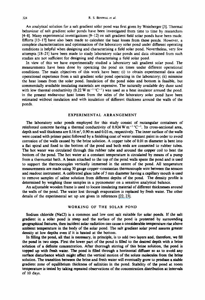
An analytical solution for a salt gradient solar pond was first given by Weinberger [3]. Thermal behaviour of salt gradient solar ponds have been investigated from time to time by researchers [4-8]. Many experimental investigations [9-12] on salt gradient field solar ponds have been made. Efforts [13-17] have also been made to calculate the heat losses from these ponds. However, a complete characterisation and optimisation of the laboratory solar pond under different operating conditions is helpful when designing and characterising a field solar pond. Nevertheless, very few attempts [18-21] have been made to study laboratory solar ponds and data obtained from such studies are not sufficient for designing and characterising a field solar pond.
In view of this we have experimentally studied a laboratory salt gradient solar pond. The measurements have been done by operating the pond six times under different operational conditions. The main objectives of this work have been: (i) to obtain experimental data and operational experience from a salt gradient solar pond operating in the laboratory; (ii) minimise the heat losses from the solar pond. Insulation of the pond sides and bottom is feasible, but commercially available insulating materials are expensive. The naturally available dry dune sand with low thermal conductivity (0.22 W m-J °C -j ) was used as a heat insulator around the pond. in the present endeavour heat losses from the sides of the laboratory solar pond have been estimated without insulation and with insulation of different thickness around the walls of the ponds.
EXPERIMENTAL ARRANGEMENT
The laboratory solar ponds employed for this study consist of rectangular containers of reinforced concrete having a thermal conductivity of 0.924 W m-J°C - J. Its cross-sectional area, depth and wall thickness are 0.16 m 2, 0.90 m and 0.03 m, respectively. The inner surface of the walls were coated with primer paint followed by a finishing coat of water resistant paint in order to avoid corrosion of the walls caused by the brine solution. A copper tube of 0.01 m diameter is bent into a fiat spiral and fixed to the bottom of the pond and both ends are connected to rubber tuhes. The hot water was circulated through this rubber tube and around the copper coil to heat the bottom of the pond. The hot water at a constant temperature is circulated by means of a pump from a thermostat bath. A beam attached to the top of the pond walls spans the pond and is used to support the thermocouples vertically immersed in the centre of the pond. All temperature measurements are made using 30 gauge copper-constantan thermocouple wire between the sensors and readout instrument. A calibrated glass tuhe of 5 mm diameter having a capillary mouth is used to remove samples of saline solution from different depths of the pond. The density profile is determined by weighing these samples in a pycnometer on a sensitive analytical balance.
An adjustable wooden frame is used to locate insulating material of different thicknesses around the walls of the pond. The water lost through evaporation is replaced by fresh water. The other details of the experimental set up are given in references [22, 23].
WORKING OF THE SOLAR POND
Sodium chloride (NaCI) is a common and low cost salt suitable for solar ponds. If the salt gradient in a solar pond is steep and the surface of the pond is protected by surrounding geographical features, then incident solar radiation can cause a considerable temperature rise above ambient temperature in the body of the solar pond. The salt gradient solar pond assures greater density at low depths even if it is heated at the bottom.
In filling the pond, all that is necessary, in principle, is to add two layers and, therefore, w© fill the pond in two steps. First the lower part of the pond is filled to the desired depth with a brine solution of a definite concentration. After thorough stirring of this brine solution, the pond is topped up with fresh water. The pond is filled through a horizontal diffuser so as to avoid any surface disturbance which might affect the vertical motion of the solute molecules from the brine solution. The transition between the brine and fresh water will eventually grow to produce a stable gradient zone of equilibrium thickness of salinities in the pond. Stability of the pond at room temperature is tested by taking repeated observations of the concentration distribution at intervals of 10 days.

Solar pond thermal behaviour 325
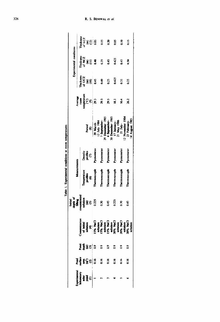
The ponds were initially filial with 15% S ~ i ~ : chi&ide soiution on 20 March 1984, 7 September 1985 and 4 September 1985 up to depths one fourth (0.225 m), one third (0.30 m) and a half (0.45 m), respectively, measured from the bottom of the pond, and the remaining depth of the ponds was filled with fresh water. These pond states are designated pond 1, pond 2 and pond 3, respectively. Concentration profiles were observed every I0 days at room temperature until a stable concentration gradient had been set up. This took nearly a month in each case. Having thus obtained stable density gradients, the ponds were then heated from the bottom at 35, 40, 45 and 50°C. Density profiles and temperature profiles along the depth of the pond were measured after the stabilization of temperature gradients. However, for the stability of temperature gradient, the temperatures were measured inside the pond at definite regular intervals of time.
The ponds were again filled on 17 January 1986, 21 July 1984 and 22 February 1985, up to depths of one fourth (0.225 m), one third (0.30 m) and a half (0.45 m), respectively, with 20% sodium chloride solution. These situations are termed pond 4, pond 5 and pond 6, respectively. After getting stable concentration gradients, heating of the ponds commenced on 28 February 1986, 21 August 1984 and 26 March 1985 from 35°C up to 50°C in steps of 5°C.
An adjustable wooden frame was used to place insulating material of different thicknesses surrounding the walls of the ponds. Dry dune sand with a thermal conductivity value of 0.22 W m -m °C -s and a density of 1520 kg m -3, was used. The temperature distribution inside the pond, at the outer surface of the pond walls and the outer surface of insulating sheaths was measured for the above operating temperatures.
In the present endeavour heat losses from the sides of the ponds have also been estimated with and without insulation using the above measurements. Heat losses due to convection and radiation from the surface of the ponds were not considered here, because the difference in temperature between the surface layer and ambient is negligible. The heat losses from the bottom of the pond have not been studied in all the above cases as the bottom of the pond rested on the floor of the room.
CALCULATION OF HEAT LOSSES
(a) Side heat losses
In steady state, the heat losses from the side walls of a rectangular pond with and without insulation are estimated as follows.
Without insulation. The rate of heat flow per unit area from the side walls of a rectangular pond is constant and is given [24] by
q, ffi ~ (T , - 72), (l)
where dm is the thickness of the wall of the pond, ~.~ is the thermal conductivity of the material of the wall and T, and /'2 are the temperatures of the inner and outer surfaces of the walls of the pond, respectively.
With insulation. If an insulating material of effective thermal conductivity ~2 with thickness d2 is used to surround the walls of the pond, then the influence of insulation on side heat losses is accounted for by estimating the effective thermal conductivity of the composite system formed by the pond wall and insulator. Owing to close contact between the layers, the adjacent surfaces have one and the same temperature. Thus the rate of heat loss per unit area through the walls of the pond and insulation is given by
TI-- T 3 q2 ffi f d, d2~' (2)
\T, where T3 is the temperature at the outer surface of the insulation sheath.
The side losses from the upper convective zone are assumed to be negligible as the temperature of the inner and the outer surfaces of the pond walls of the UCZ are almost equal and are equal to the ambient temperature. Side heat losses per unit area per unit time from the non-convective zone may be estimated using mean temperatures of LCZ and UCZ, assuming linear temperature
Exp
erim
enta
l Po
nd
labo
rato
ry
surf
ace
Pond
C
om~
n~at
ion
sola
r ar
ea
dept
h o
f in
itial
po
ad
(in 2 )
(m
) so
lutio
n (i)
(2
) (3
) (4
) I
0.16
0.
9 15
% N
aCI
solu
tion
2 0.
16
0.9
15%
NaC
I so
lutio
n 3
0.16
0.
9 15
% l
qltc
I so
luti
o,
4 0.
16
0.9
20%
lqa
CI
solu
tion
5 0.
16
0.9
20%
NIt
CI
solu
tion
6 0.
16
0.9
20%
NaC
I so
lutio
n
Tab
le
I. E
xper
imen
tal c
ondi
tions
at
roo
m t
empe
ratu
res
Initi
al
de
. o
f Ed
ging
M
easu
rem
ents
co
mam
trat
ed
solu
tion
Tem
pera
ture
D
ensi
ty
(m)
prof
iles
prof
iles
Peri
od
(5)
(6)
(7)
(8)
0.2
25
T
be
rmo
cou
ple
Pyc
nom
eter
20
Mar
ch-
12 J
uly
1984
0
.30
T
berm
ocou
ple
Pycn
omet
er
7 Se
ptem
ber-
29
Dec
embe
r 19
85
0.4
5
The
rmoc
oupl
e Py
cnom
eter
4
Scl~
embe
r-
30 D
ecem
ber
1985
0
.22
5
The
rmoc
oupl
e P
yro
met
er
17 J
anua
ry-
21 M
ay 1
986
0.3
0
The
rmoc
oupl
e Py
cnom
eter
21
Jul
y-
12 N
ovem
ber
1984
0
.45
T
he
rmo
cou
ple
Pyc
nom
eter
22
Feb
ruar
y-
14 A
ugus
t 19
85
Exp
erim
enta
l co
nditi
ons
Ave
rage
ro
om
Th
ick
ne
ss
T
hic
kne
ss
Thi
ckne
ss
tem
pera
ture
o
f U
CZ
of
NC
Z
of
LC
Z
(°C
) (m
) (m
) (m
) (9
) (1
0)
(I I)
0
2)
29.3
0.
45
0.40
0.
05
29.5
0.
40
0.35
0.
15
29.5
0.
25
0.45
0.
20
18.3
0.
425
0.42
5 0.
05
30.4
0.
35
0.45
0.
10
26.2
0.
25
0.50
0.
15
z l-
Solar pond thermal behaviour 327
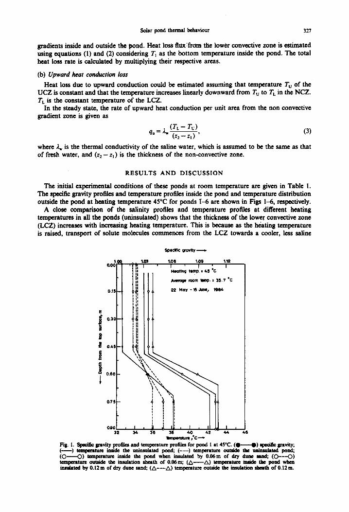
gradients inside and outside the pond. Heat loss flux:fr0m the lower convective zone is estimated using equations (1) and (2) considering Tt as the bottom temperature inside the pond. The total heat loss rate is calculated by multiplying their respective areas.
(b) Upward heat conduction loss
Heat loss due to upward conduction could be estimated assuming that temperature Tu of the UCZ is constant and that the temperature increases linearly downward from Tu to TL in the NCZ. TL is the constant temperature of the LCZ.
In the steady state, the rate of upward heat conduction per unit area from the non convective gradient zone is given as
(TL- Tu) q" = ~ (z2 - z,) ' (3)
where A,, is the thermal conductivity of the saline water, which is assumed to be the same as that of fresh water, and (z2- zl) is the thickness of the non-convective zone.
R E S U L T S A N D D I S C U S S I O N
The initial experimental conditions of these ponds at room temperature are given in Table !. The specific gravity profiles and temperature profiles inside the pond and temperature distribution outside the pond at heating temperature 45°C for ponds I-6 are shown in Figs 1-6, respectively.
A close comparison of the salinity profiles and temperature profiles at different heating temperatures in all the ponds (uninsulated) shows that the thickness of the lower convective zone (LCZ) increases with increasing heating temperature. This is because as the hc~ating temperature is raised, transport of solute molecules commences from the LCZ towards a cooler, less saline
S p ~ l f i c W o v ~ ,
I,lii I I
o.,,_l If; ! ; I tit
_ ' [ i t+n ' I ' ! | I I,
./ !11
0.75
0.90 , I , 3 2 3 4
E
" 0.3C
0.4S
J J=
0 .80
1.03 I
1.06 1-09 1.12 i
I ' I "C I 14eoting temp. : 4S
Av l fog¢ room timp. : 35 .7 "C
22 Nloy - 15 June~ 198&
t
+
#e - ~ 40 42 11m~ero~m ,C---+
I t
46
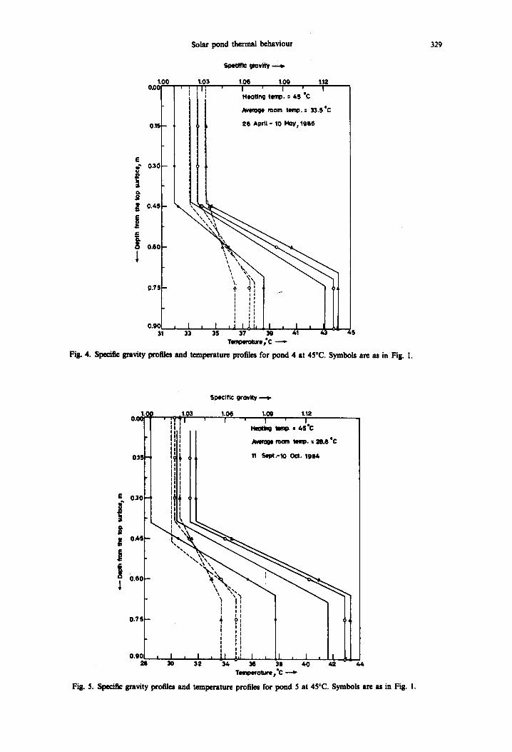
Fig. I. Spe~fic gravity profiles and temperature profiles for pond 1 at 45°C. ( H ) gagilk gravity; ( ) ~ t u r e inside the unimulated pond; ( - - - ) temperature outside the ~ i -~dated pond; (O O) temperature inside the pond when insulated by 0.06m of dry dune mad; ( O - - - O ) temperature outside the insulation sheath of 0.06 m; ( ~ A) temperature inside the pond when insulated by 0.12m of dry dune sand; ( A - - - A ) temperature outside the insulation sheath of 0.12m.

328 R .S . BENIWAL et al.
o ~ ~° •
':'.
o.18 - ,~
SpeCific grovlty----~
1.03 1.06 1.0g I ~ I ~ I
1.12 ' I
Heotlng t emp . : ,;.5 *C
Averoge room temp. = 21.4 "C
16 Oec.-2~ Dec. 1985.
" 0,10-144
o.,. - a . ,,,:,,,
0.75
0.g0 i :L~II I ~ . ~ , I , I , I . , 2 S 34 37 40 43
Temperoture, *C --*"
Fig. 2. Specific gravity profiles and temperature profiles for pond 2 at 45°C, Symbols are as in Fig. l.
SINId~ grov l ty
o~, ' r ,.o3 , ' ~ l , ,.o91 , '~1 l, teottng temp. = 45 *C
ii A~, ,w, ~ n t , ~ : 21.4"c
o .1 , - i; ~ t 6 o , : . - 2 7 o ~ lgss J l
i:
• •
£ 0.4S 1 ~ ",,,,
J I o o.6o 4
1 i
I
0.75 1 ~,, I
i
J
' L 0 . g 0 , , ! i I I I n -31 36 37 40 - - 6,t
1 " i m p u r e , " c - - ~
Fig. 3. Specific gravity profiles and temperature profiles f@r pond 3 at 45°C. Symbols are as in Fig. l,
Solar pond t~ennaJ betmviou,r
1.00 0.00
0.15
E
0.4S
0.80
i 0.75--
0.g0 31
, I
3 3
1 . 0 3 ll;
s t ~ grov~
1.0G 1.01) 1.12 ' I ' I ' I
Heotlng ttmp. : 45 *C
Avtroge room temp. : 33.5 "C
28 April = 10 MOy; lgQ6
T II- }ll , I , I I l i . l l , I , d 11
3s 3~- ~ 41 43 - - 4s T ,m,~ , re ;C - - -
Fig. 4. Specific gravity profiles and temperature profiles for pond 4 at 45°C. Symbols are as in Fig. I.
329
Specific grovRy
0.0~ OJ, , ;~ !1.051 , 1.061 ' 1.091 , !.121
st Hc~ng I m ~ = 4S*C I I I J
I l l l - - m o r n temp. : I . o ' C I i I
i l l l
!iii • i l l l
!111 • i l l ' iLJ t
-,.\:,->,
I ! I I
I
O.TS t i: t I t l
o . o o i , , , , . , i J , , , . , . Temperoture pOc
Fig. 5. Sl)eCific gravity profiles and t~npcraturc profiles for pond 5 at 45°C. Symbols are as in Fig. I.

330 R . S . BENIWAL et aL
s
n o
e~
e , o r ~
1.0( 0.0(
0.1!
0.3(3
0.41 -
0 . 6 0
0.7!
0 .9¢ 34
1.03
1
.I i , I A - t,o 4 2 - t.~;
r e m p e f o t u r e / , * C --.e.
S p e c i f i c g r a v i t y
1.06 1.09 1,12 I ' I . " I Heott~ temp. = 65 C
Average room temp. = 3~,.9"C
13 June - g JulYt 1985
, I. 3(5 46
Fig. 6. Specific gravity profiles and temperature profiles for pond 6 at 45°C. Symbols are as in Fig. 1.
region, losing heat and salt by diffusion and thus decreasing the salt density of the LCZ. This process continues until a uniform density (less than the density at lower temperatures) of the solution of the storage zone is attained. This causes contraction of the NCZ. However, the thickness of the UCZ is found to he independent of heating temperature.
The thicknesses of upper convective, non-c0nvective and lower convective zones in all the six ponds at these heating temperatures are shown in Table 2. It appears from Table 2 that the thicknesses of LCZ and NCZ not only depend upon the heating temperature, but also the initial filling depth of the pond, which also controls the thickness of the NCZ at a particular constant temperature. The thickness of the NCZ has been found to decrease with increasing heating temperature. At 50°C the thickness, for example, has reduced to 0.05 m and 0. ! 5 m compared to
Table 2. Thickneues (m) of the upper convective, non.convective and lower convective zones at various heatin~ tempe~tutes in all ~ p~ds
Heroins temperature
Pond 35°C 40°C 45°C 50°C
I UCZ 0.45 0.45 0.45 0.45 NCZ 0.40 0,375 0.275 0.10 LCZ 0.05 0.075 0.175 0.35
2 UCZ 0.40 0.40 0.40 0.40 NCZ 0.35 0.25 0.15 0.05 LCZ 0.15 0.25 0.35 0.45
3 UCZ 0.25 0.25 0.25 0.25 NCZ 0.425 0.30 0.15 0.05 LCZ 0.225 0.35 0.50 0.60
4 UCZ 0.425 0.425 0.425 0.425 NCZ 0.40 0.35 0.30 0.15 LCZ 0.075 0.125 0.175 0.325
5 UCZ 0.35 0.35 0.35 0.35 NCZ 0.425 0.40 0.325 0.15 LCZ 0.125 0.15 0.225 0.40
6 UCZ 0.25 0.25 0.25 0.25 NCZ 0.50 0.45 0.35 0.15 LCZ 0.15 0.20 0.30 0.50
Heating temperature
Solar pond thermal l~baviour
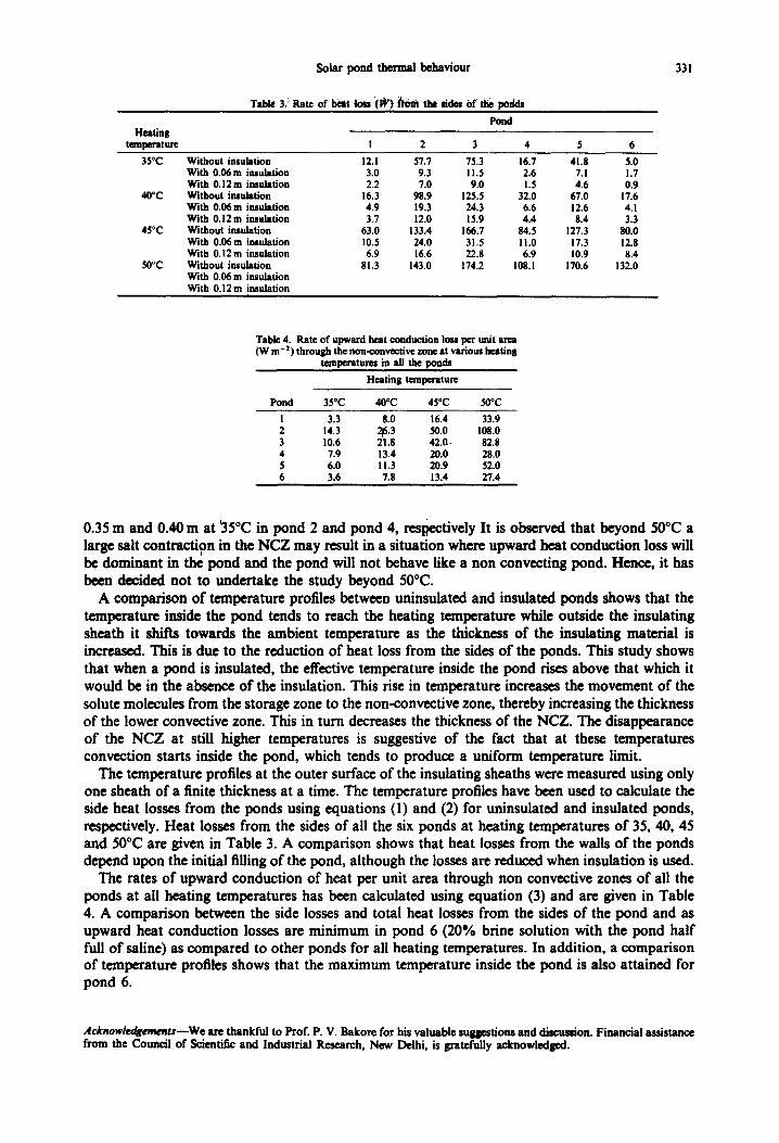
Table 3. Rate of heat lois (W) ~ the *ides of ~ podds
Pond
I 2 3 4
331
35°C Without insulation With 0.06 m insulation With 0.12m insulation
40°C Without insulation With 0.06 m insulation With 0.12 m insulation
45°C Without insulation With 0.06 m insulation With 0.12m insulation
50°C Without insulation With 0.06 m insulation With 0.12m insulation
12.1 57.7 75.3 16.7 41.8 5.0 3.0 9.3 I 1.5 2.6 7. I 1.7 2.2 7.0 9.0 1.5 4.6 0.9
16.3 98.9 125.5 32.0 67.0 17.6 4.9 19.3 24.3 6.6 12.6 4.1 3.7 12.0 15.9 4.4 8.4 3.3
63.0 133.4 166.7 84.5 127.3 80.0 10.5 24.0 31.5 11.0 17.3 12.8 6.9 16.6 22.8 6.9 10.9 8.4
81.3 143.0 174.2 108.1 170.6 132.0
Table 4. Rate of upward heat conduction 1o~ per unit area (Wm -2) through the non-convective zone at various heating
temperatm~ in all the ponds
Heating temperature
Pond 35°C 40°C 45°C 50°C
I 3.3 8.0 16.4 33.9 2 143 5o0 1080 3 10.6 42.0- 82.8 4 7.9 13.4 20.0 28.0 5 6.0 , I i.3 20.9 52.0 6 3.6 7.8 13.4 27.4
0.35 m and 0.40 m at 35°C in pond 2 and pond 4, resl~ectively It is observed that beyond 50°C a large salt contraction in the NCZ may result in a situation where upward heat conduction loss will be dominant in the pond and the pond will not behave like a non conveeting pond. Hence, it has been decided not to undertake the study beyond 50°C.
A comparison of temperature profiles between uninsulated and insulated ponds shows that the temperature inside the pond tends to reach the heating temperature while outside the insulating sheath it shifts towards the ambient temperature as the thickness of the insulating material is increased. This is due to the reduction of heat loss from the sides of the ponds. This study shows that when a pond is insulated, the effective temperature inside the pond rises above that which it would be in the absence of the insulation. This rise in temperature increases the movement of the solute molecules from the storage zone to the non-convective zone, thereby increasing the thickness of the lower convective zone. This in turn decreases the thickness of the NCZ. The disappearance of the NCZ at still higher temperatures is suggestive of the fact that at these temperatures convection starts inside the pond, which tends to produce a uniform temperature limit.
The temperature profiles at the outer surface of the insulating sheaths were measured using only one sheath of a finite thickness at a time. The temperature profiles have been used to calculate the side heat losses from the ponds using equations (1) and (2) for uninsulated and insulated ponds, respectively. Heat losses from the sides of all the six ponds at heating temperatures of 35, 40, 45 and 50°C are given in Table 3. A comparison shows that heat losses from the walls of the ponds depend upon the initial filling of the pond, although the losses are reduced when insulation is used.
The rates of upward conduction of heat per unit area through non convective zones of all the ponds at all heating temperatures has been calculated using equation (3) and are given in Table 4. A comparison between the side losses and total heat losses from the sides of the pond and as upward heat conduction losses are minimum in pond 6 (20% brine solution with the pond half full of saline) as compared to other ponds for all heating temperatures. In addition, a comparison of temperature profiles shows that the maximum temperature inside the pond is also attained for pond 6.
Aeknowtedgemems~We are thankful to Pro£ P. V. Bakore for his valuable suggestions and discussion. Financial assistance from the Council of Scientific and Industrial Research, New Delhi, is gratefully acknowledged.
332 R.S. BE~nWXL et al.
R E F E R E N C E S
1. C. E. Nielsen, Non-convective salt gradient solar ponds, in Solar Energy Technology Handbook, (Edited by W. C. Dickinson and P. N. Cheremisinoff). Marcel Dekker, New York (1980).
2. H. Tabor, Solar ponds, Sol. Energy 27, 181 (1981). 3. H. Weinberger, The physics of the solar pond, Sol. Energy 8, 45 (1964). 4. A. Rabl and C. E. Nielsen, Solar ponds for space heating, Sol. Energy 17, 1 (1975). 5. J. R. Hull, Computer simulation of solar pond thermal behaviour, Sol. Energy 25, 33 (1980). 6. M. N. Hawlader and B. J. Brinkworth, An analysis of the non-convecting solar pond, SOl. Energy 27, 195 (1981). 7. K. Kinose and K. Sakurai, Study on collection and storage of solar heat by solar pond with the vertical gradient of
salt concentration (I), Bull. NRIAE, 19, 65 (1980). 8. R. S. Beniwal, R. Singh, N. S. Saxena and R. C. Bhan~lari, Thermal behavionr of salt gradient solar ponds, J. Phys.
D appl. Phys. 20, 1067-1071 (1987). 9. F. Zangrando, Observation and analysis of a full-scale experimental salt gradient solar pond, Ph.D. Thesis, University
of New Mexico (1979). 10. C. E. Nielsen and J. Kamal, The 400 m 2 solar pond: one year ol~eration, in Proceedings of the American Section of the
International Solar Energy Society, pp. 381-385, Phoenix, Arizona (1980). 11. L. J. Wittenberg and M. J. Harris, Construction and Start up performance of the Miamisburg salt gradient solar pond,
A.S.M.E. J. Sol. Energ F Engng 103, 11 (1981). 12. J. R. Hull, Y. S. Cha, W. T. Sha and W. W. Schertz, C o n s ~ o n and first year's operational results of the ANL
research salt gradient solar pond, in Proceedings of the American Solar Energy Society, pp. 197-202, Houston, Texas (1982).
13. C. E. Nielsen, Salt gradient solar pond development. USDOE Solar Heating and Cooling Contractor's Meeting, Washington, D.C. (1978).
14. J. R. Hull, K. V. IAu, W. T. Sha, J. Kamal and C. E. Nielsen, Dependence of ground heat loss upon solar pond size and perimeter insulation: calculated and experimental results. Sol. Energy 33, 25 (1984).
15. R. S. lkniwal, R. Singh and D. R. Chaudhary, Heat losses from a salt gradient solar pond, Appl, Energy 19, 273 (1985). 16. J. R. Hull, Solar pond ground loss to a moving water table, Sol. Energy 35, 211 (1985). ! 7. R. S. lleniwal, R. Singh, R. N. Pande, D. R. Chaudhary and P. V. Bakore, Thermal performance of solar ponds under
different soil conditions. J. Heat Recovery Systems & ClIP 7, 139 (1987). 18. N. Chepurniy and S. B. Savage, An analytical and experimental investigation of a laboratory solar pond model, ASME,
74 WA/Soi.3 (1974). 19. C. L. Gupta and S. M. Patel, Experimental investigation of laboratory solar ponds, in Proceedings of the NSEC, Solar
Energy Society oflndia, pp. 119-125, Bombay (1979). 20. K. Kinose, Storage temperature of salt gradient solar pond, ASCEJ. Energy Engng 110, 113 (1984). 21. M. A. ~|badidy, B. G. Nimmo and S. Zubalr, Operation of a small scale salt gradient solar pond: e x ~ t a l results,
A.S.M.E.J. Sol. Energy Engng IN, 55 (1986). 22. R. S. Beniwal, R. Singh and N. S. Saxena, Thermal Storage and investigation on a laboratory solar pond. J. Heat
Recovery Systems 4, 401 (1984). 23. R. S. Beniwal, R. Singh, N. S. Saxena and R. C. Bhandari, Characterisation and heat losses from a laboratory salt
gradient solar pond, J. Heat Recovery Systems 6, 105 (1986). 24. M. M. Kheyev and S. Semyonov, Fundamentals of Heat Transfer, p. 21. Peace Publication, Moscow (1955).