Experimental study and numerical modelling of drying characteristics of apple slices
11
Ž . Surface and Coatings Technology 135 2000 98]108 Experimental study and numerical modelling of the nickel ž / oxide coating on the Ni 111 surface N. Vallino a , L. Gaillet a , L. Lahoche a, U , J.M. Roelandt a , V.L. Lorman b , G. Moulin a , S.B. Rochal c a Departement GSM, Laboratoire Rober ¤ al, UMR-CNRS, Uni ¤ ersite de Technologie de Compiegne, France ´ ´ ` b LPM, CNRS ] Uni ¤ ersite Montpellier 2, Place Eugene Bataillon, 34095 Montpellier, France ´ c Faculty of Physics, Rosto¤ State Uni ¤ ersity, 5 Zorge St., 344090 Rosto¤ -on-Don, Russia Received 29 July 1999; accepted in revised form 18 July 2000 Abstract Ž . The evolution of the nickel oxide coating developed on the mono-crystalline Ni 111 surface was studied both experimentally and by means of numerical modelling. The NiOrNi system was submitted to a high-temperature creep in the oxygen atmosphere. 18 Ž Using the O diffusion method we were able to observe several deformation modes diffusional creep, gliding at the interfaces, . etc. and periodic crack generation perpendicular to the stress direction. The periodicity of the cracks array depends strongly on the external stress applied to the oxide scale. Two-step numerical modelling of the process was performed using first a simplified 1D model and then the 3D finite elements approach. The modelling procedure takes into account epitaxial deformations due to the scale ordering and to the mismatch of the lattice parameters, the growth process and the periodic crack generation. Ž . Identification of the visco-elastic material law permits then to obtain the strain and the stress distribution in the scale and in the substrate. The comparison of the experimental data with the numerical results will allow the formulation of several criteria for the oxide scale adherence. Q 2000 Elsevier Science B.V. All rights reserved. Keywords: Oxide coatings; Interface; Finite element method; Mechanical behaviour; Cracks; Micro-structural analysis 1. Introduction Mechanical resistance of metallic materials submit- ted to the action of an aggressive atmosphere at high temperature depends mainly on the adherence of the wx protective oxide layer developed on the substrate 1. Coating lifetime is then related to the thermodynamic and mechanical stability of the oxide scale under the stress both external and generated in the scale during the substrate oxidation process and the cooling ] heat- U Corresponding author. Tel.: q33-3-22-82-78-84; fax: q33-3-22- 82-78-91. Ž . E-mail address: [email protected] ypicardie.fr L. Lahoche . ing cycling. Oxide scale exfoliation leads to the degra- dation of the metallic parts in an industrial environ- ment and to higher production costs. This explains the interest of several branches of industry, like aerospace or chemical to the problem. Though this subject was w x already studied using different approaches 2 ] 4 the detailed determination of the stress origin and magni- tude remains difficult. Ž Numerous experimental techniques destructive or . not were developed for this purpose. Among them one can cite X-ray diffraction or deflection method to eval- uate the level and to determine the nature of the growth stress during an isothermal oxidation and ther- wx mal stresses during cooling process 5 . However, no clear-cut conclusion could be made. In this situation a 0257-8972r00r$ - see front matter Q 2000 Elsevier Science B.V. All rights reserved. Ž . PII: S 0 2 5 7 - 8 9 7 2 00 00912-9
-
Upload
independent -
Category
Documents
-
view
3 -
download
0
Transcript of Experimental study and numerical modelling of drying characteristics of apple slices
Ž .Surface and Coatings Technology 135 2000 98]108
Experimental study and numerical modelling of the nickelž /oxide coating on the Ni 111 surface
N. Vallinoa, L. Gaillet a, L. Lahochea,U, J.M. Roelandta, V.L. Lormanb,G. Moulina, S.B. Rochalc
aDepartement GSM, Laboratoire Rober al, UMR-CNRS, Uni ersite de Technologie de Compiegne, France´ ´ `bLPM, CNRS ] Uni ersite Montpellier 2, Place Eugene Bataillon, 34095 Montpellier, France´
cFaculty of Physics, Rosto¨ State Uni ersity, 5 Zorge St., 344090 Rosto¨-on-Don, Russia
Received 29 July 1999; accepted in revised form 18 July 2000
Abstract
Ž .The evolution of the nickel oxide coating developed on the mono-crystalline Ni 111 surface was studied both experimentallyand by means of numerical modelling. The NiOrNi system was submitted to a high-temperature creep in the oxygen atmosphere.
18 ŽUsing the O diffusion method we were able to observe several deformation modes diffusional creep, gliding at the interfaces,.etc. and periodic crack generation perpendicular to the stress direction. The periodicity of the cracks array depends strongly on
the external stress applied to the oxide scale. Two-step numerical modelling of the process was performed using first a simplified1D model and then the 3D finite elements approach. The modelling procedure takes into account epitaxial deformations due tothe scale ordering and to the mismatch of the lattice parameters, the growth process and the periodic crack generation.
Ž .Identification of the visco-elastic material law permits then to obtain the strain and the stress distribution in the scale and in thesubstrate. The comparison of the experimental data with the numerical results will allow the formulation of several criteria forthe oxide scale adherence. Q 2000 Elsevier Science B.V. All rights reserved.
Keywords: Oxide coatings; Interface; Finite element method; Mechanical behaviour; Cracks; Micro-structural analysis
1. Introduction
Mechanical resistance of metallic materials submit-ted to the action of an aggressive atmosphere at hightemperature depends mainly on the adherence of the
w xprotective oxide layer developed on the substrate 1 .Coating lifetime is then related to the thermodynamicand mechanical stability of the oxide scale under thestress both external and generated in the scale duringthe substrate oxidation process and the cooling]heat-
U Corresponding author. Tel.: q33-3-22-82-78-84; fax: q33-3-22-82-78-91.
Ž .E-mail address: [email protected] ypicardie.fr L. Lahoche .
ing cycling. Oxide scale exfoliation leads to the degra-dation of the metallic parts in an industrial environ-ment and to higher production costs. This explains theinterest of several branches of industry, like aerospaceor chemical to the problem. Though this subject was
w xalready studied using different approaches 2]4 thedetailed determination of the stress origin and magni-tude remains difficult.
ŽNumerous experimental techniques destructive or.not were developed for this purpose. Among them one
can cite X-ray diffraction or deflection method to eval-uate the level and to determine the nature of thegrowth stress during an isothermal oxidation and ther-
w xmal stresses during cooling process 5 . However, noclear-cut conclusion could be made. In this situation a
0257-8972r00r$ - see front matter Q 2000 Elsevier Science B.V. All rights reserved.Ž .PII: S 0 2 5 7 - 8 9 7 2 0 0 0 0 9 1 2 - 9
( )N. Vallino et al. r Surface and Coatings Technology 135 2000 98]108 99
modelling of the structural behaviour at high tempera-ture together with numerical finite element modellingof the strain and stress state of the scale permits anunderstanding of the peculiarities of the thermo-mech-anical loading of the metalroxide system.
The aim of this article is to study the mechanicalbehaviour of a single-crystalline nickel sample de-formed by creep in an oxygen atmosphere with theŽ .111 Ni surface submitted to oxidation. In our previous
w xstudies 6]8 we have proposed a model of order]dis-order transformation in a three-dimensional NiOrNiinterface, which results in qualitatively different growthregimes. It was shown that together with the well-known
w xvacancy precipitation mechanism 9 it leads to theduplex structure formation in the NiO scale on thenickel surface.
In the present work we study the diffusional, micro-structural and mechanical parameters of the oxide scale
Ž .on the 111 Ni surface, subjected to a strain underoxidising atmosphere both experimentally and by meansof numerical modelling. The paper is organised asfollows. In the first part, we propose a micro-structuralanalysis of the sample together with the study of theexternal stress effect and oxidation-induced stress ef-fect. Using the O18 diffusion method we are able to
Žobserve several deformation modes diffusional creep,.gliding at the interfaces, etc. and periodic crack gener-
ation perpendicular to the loading direction. We alsoshow that the periodicity of the cracks array dependsstrongly on the external stress applied to the oxidescale. In the second section we briefly review the ther-modynamics and crystallographic aspects of the scaleformation. This analysis gives the effective values ofthe growth strain in the system. Two-step numericalmodelling of the process is presented in Section 4. Thenumerical procedure introduces first a simplified 1Dmodel and then the 3D finite elements approach basedon the eight-node hexahedron discretisation, static im-plicit Simo]Taylor algorithm and a field mappingmethod. The results of the modelling which takes intoaccount epitaxial deformations due to the scale order-ing and to the mismatch of the lattice parameters, the
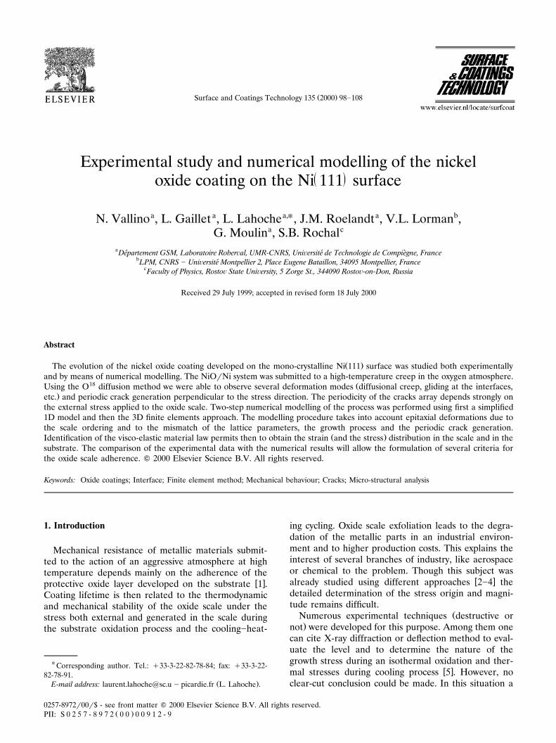
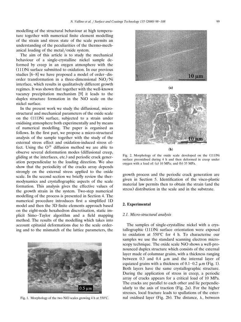
Fig. 1. Morphology of the two NiO scales growing 4 h at 5508C.
Ž .Fig. 2. Morphology of the oxide scale developed on the 111 Nisurface preoxidised during 4 h and then deformed in creep under
Ž . Ž .oxygen with a load of: a 10 MPa; and b 35 MPa.
growth process and the periodic crack generation aregiven in Section 5. Identification of the visco-plastic
Žmaterial law permits then to obtain the strain and the.stress distribution in the scale and in the substrate.
2. Experimental
2.1. Micro-structural analysis
The samples of single-crystalline nickel with a crys-Ž .tallographic 111 Ni surface orientation were exposed
to oxidation at 5508C for 4 h. To characterise oursamples we use the standard scanning electron micro-scopy technique. The oxide scale NiO shows a well-pro-nounced duplex structure which consists of the externallayer made of columnar grains, with a thickness rangingbetween 0.3 and 0.4 mm and the internal layer of
Ž .equiaxed grains with a thickness of 0.1]0.2 mm Fig. 1 .Both layers have the same crystallographic structure.During the application of stress in creep, a periodicarray of cracks appears for a critical load of 10 MPa.The cracks are parallel to each other and lie perpendic-
Ž .ularly to the axis of traction Fig. 2a . For the higherstresses, local fracture leads to spallations of the exter-
Ž .nal oxidised layer Fig. 2b . The distance, l, between

( )N. Vallino et al. r Surface and Coatings Technology 135 2000 98]108100
Fig. 3. Evolution of the distance between cracks according to theapplied stress.
Žthe cracks decreases with increasing creep loading Fig..3 .
2.2. External stress effect on NirNiO
The mechanical behaviour was studied in a specificŽ .set-up Fig. 4 . This prototype set-up enables us to
Ž .measure the mechanical parameters stress and strainŽof the NirNiO system deformed by creep or without
.mechanical loading in the oxygen environment. More-over, the stress relaxation experiments at the end ofcreep tests were performed to make our mechanicalanalysis more precise. The creep tests are carried outwith loads varying from 10 to 90 MPa. The mechanicalbehaviour in creep can be divided in two fields of
Ž .stress: a diffusional type creep Nf1.3 for low loadŽ . Ž .up to 35 MPa and a power law creep Nf3.9 for the
Ž .higher loads Fig. 5 where the total strain rate istotal N Ž .expressed as: « sA ?s A and N are constants .˙
2.3. Oxidation induced stress in NiO
To determine the stress present in initial oxide filmwithout external load, we also used a deflection set-upschematised in Fig. 6. The samples are protected onone side against oxidation by a silica layer. Annealingtreatment has been performed in vacuum for 6 h atTs4008C to relax the internal stress which mightoccur during deposition. We measured then their cur-vature with a laser device. The speed of relief is ap-proximately 10y2 MPa sy1. The curvature D of the
Ž .sample varies from negative values tension at theŽbeginning of the process to positive values compres-
. Ž .sion after 3 h of oxidation at 5508C Fig. 7 . Weobserve a state of zero stress reached after 2 h. We willreturn to the numerical modelling of the curvaturechange in Section 4 and especially Section 5.2.
3. Crystallography aspects
In our previous works we have proposed a scheme ofthermo-mechanical analysis of the NirNiO systemw x6]8 . At the first step of this analysis we determine thepossible crystallographic structure of the metalroxideinterface according to the general method given by
w xLahoche et al. 10 . This method gives the possibility todetermine the 3D structure for the interface formed bya dominant cation diffusion process. The structure ofthe 3D interface is less symmetric with respect to theequilibrium oxide one due to the ordering of the metal-lic ions in the interstices of the oxygen matrix. Thermo-dynamic description of the order]disorder transforma-tion permits the advancement of a thermodynamic
w xreason for the duplex structure formation 8 .
Fig. 4. Scheme of the deformation test set-up.

( )N. Vallino et al. r Surface and Coatings Technology 135 2000 98]108 101
w Ž .xFig. 5. Evolution of the logarithm of the strain rate ln « vs. the˙w Ž .xlogarithm of the stress ln s for creep in oxygen.
Ž .In the case of the 111 Ni surface oxidation, theorientational relationship between the metal and theNiO lattices can be obtained from low energy electron
Ž .diffraction LEED data. For intermediate temperatureŽ .above 2008C LEED observation shows a superlattice
Ž . Ž .pattern of a slightly distorted 100 NiO lattice on 111w xNi with 011 Ni direction rotated 458 with respect to
w x Ž .011 Ni. Then, the additional square pattern with 100Ž . w x w x w xNiOrr 111 Ni and 011 NiOr 011 Ni appears 11 .
At high temperature and high oxygen coverage, theequilibrium NiO structure is clearly seen.
This structure is considered to be a coincidenceŽ . Ž . w xlattice between 100 NiO and 111 Ni, so that in 010
NiO direction in the coincidence plane, the registry isattained every five NiO conventional cells and everynine Ni conventional cells. In the perpendicular direc-tion, superstructure cell parameter coincide with oneconventional cell length of both oxide and metal struc-
w xtures. The crystallographic analysis performed in 8shows that corresponding in-plane Ni-ions orderingleads to the 3D-interface with elementary translations
ª ª ªª ª ª ª ª1 1 1 1NiO NiO NiO Ž . Ž .t s5a , t sa , t sa where a 0 , a 01 2 2 3 3 1 1 22 2 2 2ª 1 1Ž .and a 0 are the primitive translations of the f.c.c.3 2 2
lattice. Corresponding ordered structure has D232 h
Ž .Fmmm space group. Low orthorhombic symmetry ofthe interface leads to the difference in the strain tensorcomponents « /« . Initial growth strain can be ob-x x y ytained from the crystallographic analysis as:
NiO Ni'Ž .5a y 9r 2 agr« s sq7.297%x x Ni'Ž .9r 2 a
NiO Ni'a y 3r2 agr Ž .« s sq3.246% 1y y Ni'3r2 a
In the following numerical modelling of the thermo-Ž .mechanical behaviour of the oxide scale on the 111 Ni
surface we will use the duplex structure of the scaledivided in the external and the internal layers together
w Ž .xwith the strain values Eq. 1 given by the crystallo-graphic analysis.
4. Numerical model
4.1. Numerical procedure
We use the numerical procedure which permits tocalculate stress and strain state in an oxide scale underexternal loading and includes the possibility to simulatecrack and defect generation in the scale. The proce-
Ž .dure can be divided into several steps Fig. 8 . On thefirst step we calculate the residual stress which exists inthe film grown on the metallic substrate using one-di-
Ž .mensional 1D growth model. It is based on the modi-w xfied version of the Bernstein model 12 and takes into
account the growth deformations and the duplex struc-ture of the oxide scale presented in the previous sec-tion. The following step realises a three-dimensional
Fig. 6. Scheme of the deflexion set-up with D curvature of the specimen, L length of the sample.

( )N. Vallino et al. r Surface and Coatings Technology 135 2000 98]108102
Fig. 7. Evolution of the displacement D for an unstrained oxide filmusing the deflection test at 5508C.
Ž .3D discretisation in the volume of the metalroxidesystem. The transfer of the values determined in theframework of the 1D model is done using the method
Ž .of diffuse approximation meshless method . Then, thecalculation associated with an external loading is per-formed with initial stress transferred. The meshingchoice is rather arbitrary and can be adapted to theeventual stress concentrations or singularities whichcan be induced, for example, by the presence of cracks.
4.2. One-dimensional model
Several 1D models for the stress calculation in anoxide scale on a metal have been proposed recentlyw x6]8,13 . However, these models do not take into ac-count the flexion of the metalroxide system induced bythe asymmetric one-face oxidation of the substrate.The model proposed in this work permits to simulateboth symmetric and asymmetric sample oxidation tak-
Fig. 8. Numerical procedure.
Žing into account epitaxial strain and inelastic one Fig..9a,b . In the following description we use the symmetry
index S of the system: Ss1 for the case of symmetricoxidation; and Ss0 for the asymmetric one. Thethickness of the scale being small with respect to itsother dimensions, one can neglect the end effects,namely, the lateral oxidation. In addition, we can sup-pose plane stress situation with s s0, which satisfiesz zequilibrium, compatibility and boundary conditions.Crystallographic analysis of the metalroxide interface
Ž . w xfor the 111 Ni oxidised surface 8 suggests that onlys and s stress components remain non-zero in thisx x y y
Ž .case no shear stress is present in the scale . Thebehaviour of both metal and oxide is supposed to bevisco-plastic during the high-temperature stage of theoxidation cycle. The strain is position-dependent andsatisfies the constitutive equation:
total el vp th gr Ž .« s« q« q« q« 2i i i i i
where «el , «vp, «th and « gr are elastic, visco-plastic,i i i ithermal and growth strain, respectively, and i standsfor x and y directions. To obtain a numerical solutionof the problem the substrate and the oxide are divided
Ž . Žin layers, MSN metal scale number and OSN oxide.scale number domains, respectively, with variable strain
and stress. The OSN value varies with time and isdirectly related to the growth law of the consideredoxide. Each new layer is created at a different timeincrement D t . The visco-plastic strain «vp is calculatedk i
²Žusing the cumulated plastic strain rate ps s y˙ eq. :N
s rK where s is the equivalent Von Mises stress,y eqK is the plastic resistance coefficient, N is the index ofthe viscosity power law and s is the elastic limit. Theyvisco-plastic strain increment is then expressed as D«vp
Ž . Ž .s 3r2 D p s rs where s is the stress deviator.D eq DThe mechanical equilibrium of the system is realised attime t when:k
Ž . Ž . Ž . Ž .Hs z ,t d zsF t Hzs z ,t d zsM tx x x x x y Ž .3Ž . Ž . Ž . Ž .Hs z ,t d zsF t Hzs z ,t d zsyM ty y y y y x
Though in the case of the sample flexion the totalstrain varies linearly with the z-coordinate normal tothe oxidation plane: «total s«qx z and D«total sD«q
ŽDx z « is the membrane strain, x is the curvature, D«and Dx are the additional strain and curvature during
.D t . The resolution of the equilibrium equations iskperformed in the framework of the Bernstein approxi-
w xmation 12 :
D« sD«m sD«ox Dx sDxm sDxox Ž .4i i ,k i ,k i i ,k i ,k
where the notations m, ox, k and i are used for the
( )N. Vallino et al. r Surface and Coatings Technology 135 2000 98]108 103
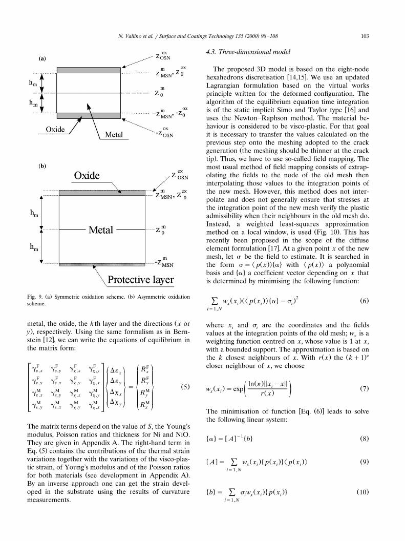
Ž . Ž .Fig. 9. a Symmetric oxidation scheme. b Asymmetric oxidationscheme.
Žmetal, the oxide, the k th layer and the directions x or.y , respectively. Using the same formalism as in Bern-
w xstein 12 , we can write the equations of equilibrium inthe matrix form:
F F F F Fg g g g ¡ ¦R« , x « , y x , x x , y D«¡ ¦ xxF F F F Fg g g g RD«« , y « , x x , y x , x yy ~ ¥~ ¥ Ž .s 5M M M M MDxg g g g Rx« , x « , y x , x x , y y¢ §DxM M M M M¢ §yg g g g R« , y « , x x , y x , x x
The matrix terms depend on the value of S, the Young’smodulus, Poisson ratios and thickness for Ni and NiO.They are given in Appendix A. The right-hand term in
Ž .Eq. 5 contains the contributions of the thermal strainvariations together with the variations of the visco-plas-tic strain, of Young’s modulus and of the Poisson ratios
Ž .for both materials see development in Appendix A .By an inverse approach one can get the strain devel-oped in the substrate using the results of curvaturemeasurements.
4.3. Three-dimensional model
The proposed 3D model is based on the eight-nodew xhexahedrons discretisation 14,15 . We use an updated
Lagrangian formulation based on the virtual worksprinciple written for the deformed configuration. Thealgorithm of the equilibrium equation time integration
w xis of the static implicit Simo and Taylor type 16 anduses the Newton]Raphson method. The material be-haviour is considered to be visco-plastic. For that goalit is necessary to transfer the values calculated on theprevious step onto the meshing adopted to the crack
Žgeneration the meshing should be thinner at the crack.tip . Thus, we have to use so-called field mapping. The
most usual method of field mapping consists of extrap-olating the fields to the node of the old mesh theninterpolating those values to the integration points ofthe new mesh. However, this method does not inter-polate and does not generally ensure that stresses atthe integration point of the new mesh verify the plasticadmissibility when their neighbours in the old mesh do.Instead, a weighted least-squares approximation
Ž .method on a local window, is used Fig. 10 . This hasrecently been proposed in the scope of the diffuse
w xelement formulation 17 . At a given point x of the newmesh, let s be the field to estimate. It is searched in
² Ž .:� 4 ² Ž .:the form ss p x a with p x a polynomial� 4basis and a a coefficient vector depending on x that
is determined by minimising the following function:
2Ž .Ž² Ž .:� 4 . Ž .w x p x a ys 6Ý x i i iis1, N
where x and s are the coordinates and the fieldsi ivalues at the integration points of the old mesh; w is axweighting function centred on x, whose value is 1 at x,with a bounded support. The approximation is based on
Ž . Ž .ethe k closest neighbours of x. With r x the kq1closer neighbour of x, we choose
Ž . < < < <ln « x yxiŽ . Ž .w x sexp 7x i ž /Ž .r x
w Ž .xThe minimisation of function Eq. 6 leads to solvethe following linear system:
y1� 4 w x � 4 Ž .a s A b 8
w x Ž . � Ž .4² Ž .: Ž .A s w x p x p x 9Ý x i i iis1, N
� 4 Ž . � Ž .4 Ž .b s s w x p x 10Ý i x i iis1, N
( )N. Vallino et al. r Surface and Coatings Technology 135 2000 98]108104
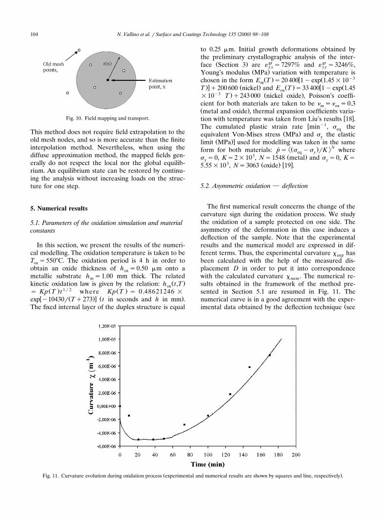
Fig. 10. Field mapping and transport.
This method does not require field extrapolation to theold mesh nodes, and so is more accurate than the finiteinterpolation method. Nevertheless, when using thediffuse approximation method, the mapped fields gen-erally do not respect the local nor the global equilib-rium. An equilibrium state can be restored by continu-ing the analysis without increasing loads on the struc-ture for one step.
5. Numerical results
5.1. Parameters of the oxidation simulation and materialconstants
In this section, we present the results of the numeri-cal modelling. The oxidation temperature is taken to beT s5508C. The oxidation period is 4 h in order tooxobtain an oxide thickness of h s0.50 mm onto aoxmetallic substrate h s1.00 mm thick. The relatedm
Ž .kinetic oxidation law is given by the relation: h t,ToxŽ . 1 r 2 Ž .s Kp T t where Kp T s 0.48621246 =
w Ž .x Ž .exp y10430r Tq273 t in seconds and h in mm .The fixed internal layer of the duplex structure is equal
to 0.25 mm. Initial growth deformations obtained bythe preliminary crystallographic analysis of the inter-
Ž . gr grface Section 3 are « s7297% and « s3246%,x x y yŽ .Young’s modulus MPa variation with temperature is
Ž . w Ž y3chosen in the form E T s20 400 1yexp 1.45=10m.x Ž . Ž . w ŽT q200 600 nickel and E T s33 400 1yexp 1.45ox
y3 . Ž .=10 T q243 000 nickel oxide , Poisson’s coeffi-cient for both materials are taken to be n sn s0.3m oxŽ .metal and oxide , thermal expansion coefficients varia-
w xtion with temperature was taken from Liu’s results 18 .w y1The cumulated plastic strain rate min , s theeq
Ž .equivalent Von-Mises stress MPa and s the elasticyŽ .xlimit MPa used for modelling was taken in the same
²Ž . :Nform for both materials: ps s ys rK where˙ eq y5 Ž .s s0, Ks2=10 , Ns1548 metal and s s0, Ksy y
3 Ž . w x5.55=10 , Ns3063 oxide 19 .
5.2. Asymmetric oxidation } deflection
The first numerical result concerns the change of thecurvature sign during the oxidation process. We studythe oxidation of a sample protected on one side. Theasymmetry of the deformation in this case induces adeflection of the sample. Note that the experimentalresults and the numerical model are expressed in dif-ferent terms. Thus, the experimental curvature x hasexpbeen calculated with the help of the measured dis-placement D in order to put it into correspondencewith the calculated curvature x . The numerical re-numsults obtained in the framework of the method pre-sented in Section 5.1 are resumed in Fig. 11. Thenumerical curve is in a good agreement with the exper-
Žimental data obtained by the deflection technique see
Ž .Fig. 11. Curvature evolution during oxidation process experimental and numerical results are shown by squares and line, respectively .

( )N. Vallino et al. r Surface and Coatings Technology 135 2000 98]108 105
.Fig. 7 . All the typical characteristics of the process,namely the time of the maximal deflection togetherwith the time of the curvature reversal, can be easily
Ž .found in the results of numerical modelling: i themaximal curvature x is obtained for the time tf40max
Ž .min; and ii the curvature sign inversion takes placefor the time tf110 min.
5.3. Crack formation during oxidation of a loaded sample
Another application of the proposed schemeconcerns the influence of the crack formation on themechanical behaviour of the symmetrically oxidisedŽ .111 Ni sample which shows no flexion effect. In thismodel, the results obtained by the 1D modelling ofstress and strain in a crack-free sample are then in-jected into the 3D model of a sample with a cracksarray and serve as initial data. After the mapping of theinitial strain, stress and internal variables, we computethe behaviour of the coated cracked metallic structureunder mechanical load. To obtain the new mechanicalequilibrium in the presence of cracks, one should rear-range the boundary conditions: the crack lips are taken
�w xin the form of free edges s ns0, where n is aŽ .4normal to the surface S xs0 . New boundary condi-
tions can be formulated taking into account thesymmetry of the problem in the following way: U s0x
Ž . Ž . Ž .for S xs0 , U s0 for S ys0 and U s0 for S zs0 .y zThe mechanical load is applied at the fixed rate «s2.5˙=10y2 sy1. The cracks appear in the sample perpen-
Ž .dicular to the x-axis Fig. 12 . The numerical results forthe s stress at the oxide surface are presented in Fig.x x13. These results are in agreement with the stress
w xdistribution obtained by Nicholls et al. 20 . The crackperturbs the tensile stress distribution which decreasesand attains zero level at the crack lips, its maximalvalue s being stabilised far from the core in the`
Fig. 12. Calculation principles for crack generation.
middle between two cracks. The maximum value de-pends strongly on the loading time. In the beginningof the process s varies from s ts0 s s110 MPa to` `
s ts100 s s2500 MPa with following stabilisation around`
Žthis value of course, this result is obtained withouttaking into account the possibility of additional crack
.formation which can relax the stress .
6. Conclusion
In the first experimental part of this work, we haveshown the influence of the external load on the cracksformation in the NirNiO system. The creep tests havebeen carried out in order to identify the behaviour lawof both compounds; they have reveal two qualitativelydifferent regimes of the system evolution. In the sec-ond part of the paper, we have developed a general 1D
Ž .model of the symmetric and asymmetric growth of theoxide on the metallic substrate. It is accompanied withthe crystallographic and thermo-dynamical analysis of
Ž .Fig. 13. Calculated stress evolution s ss x in the oxide scale in the presence of cracks.x x x x

( )N. Vallino et al. r Surface and Coatings Technology 135 2000 98]108106
the cation oxidation phenomenon. The model takesinto account different types of strains: epitaxial, growthand thermal ones together with the visco-plastic be-haviour of both compounds and temperature variationof their physical parameters.
The results of the 1D modelling are in a goodagreement with the experimental data on the deflexionof the asymmetrically oxidised sample. The 3D finiteelement model proposed in our work permits the studyof the behaviour of the metalroxide system in thepresence of cracks array. The stress level evolution atthe surface of the oxide with cracks during the loadingprocess has been estimated. This work constitutes anew numerical method which can be developed andgeneralised to obtain quantitative criteria for oxidecoating adherence both during growth and loading.
Acknowledgements
The authors are indebted to Region de Picardie for´financial support in the framework of ‘Pole Regionalˆ ´MecaniquerMateriaux’.´ ´
Appendix A
2 E Em oxF Ž . Ž .g s h q 1qS h A1« , x m ox2 21yn 1ynm ox
2n E n Em m ox oxF Ž . Ž .g s h q 1qS h A2« , y m ox2 21yn 1ynm ox
E1yS oxF Ž . Ž .g s h h q2h A3x , x ox ox m22 1ynox
n E1yS ox oxF Ž . Ž .g s h h q2h A4x , y ox ox m22 1ynox
MSN m Eyzky1 mMg sS z d zÝ H« , x 2m 1ynyz mkks1
OSN ox Eyz yhky1 m oxqS z d zÝ H 2ox 1ynyz yh oxk mks1
MSN m Ezk mq z d zÝ H 2m 1ynz mky1ks1
OSN ox Ez qhk m ox Ž .q z d z A5Ý H 2ox 1ynz qh oxky1 mks1
MSN m n Eyzky1 m mMg sS z d zÝ H« , y 2m 1ynyz mkks1
OSN ox n Eyz yhky1 m ox oxqS z d zÝ H 2ox 1ynyz yh oxk mks1
MSN m n Ezk m mq z d zÝ H 2m 1ynz mky1ks1
OSN ox n Ez qhk m ox ox Ž .q z d z A6Ý H 2ox 1ynz qh oxky1 mks1
MSN m Eyzky1 mM 2g sS z d zÝ Hx , x 2m 1ynyz mkks1
OSN ox Eyz yhky1 m ox 2qS z d zÝ H 2ox 1ynyz yh oxk mks1
MSN m Ezk m 2q z d zÝ H 2m 1ynz mky1ks1
OSN ox Ez qhk m ox 2 Ž .q z d z A7Ý H 2ox 1ynz qh oxky1 mks1
MSN m n Eyzky1 m mM 2g sS z d zÝ Hx , y 2m 1ynyz mkks1
OSN ox n Eyz yhky1 m ox ox 2qS z d zÝ H 2ox 1ynyz yh oxk mks1
MSN m n Ezk m m 2q z d zÝ H 2m 1ynz mky1ks1
OSN ox n Ez qhk m ox ox 2 Ž .q z d z A8Ý H 2ox 1ynz qh oxky1 mks1
F mec th vp dy Ž .R sD F qD F qD F qD F A9x x x x x
RM sD M mec qD M th qD M vp qD M dyy y y y y
where
MSN m Eyzky1 mthD F sS Ý Hx 2m 1ynyz mkks1
th ,m th,m= D« qn D« d zŽ .x x ,k m y y ,k
OSN ox Eyz yhky1 m oxqS Ý H 2ox 1ynyz yh oxk mks1
th ,ox th ,m= D« qn D« d zŽ .x x ,k ox y y ,k
( )N. Vallino et al. r Surface and Coatings Technology 135 2000 98]108 107
MSN m Ezk mq Ý H 2m 1ynz mky1ks1
th ,m th,m= D« qn D« d zŽ .x x ,k m y y ,k
OSN ox Ez qhk m oxq Ý H 2ox 1ynz qh oxky1 mks1
th ,ox th ,ox Ž .= D« qn D« d z A10Ž .x x ,k ox y y ,k
MSN m Eyzky1 mvpD F sS Ý Hx 2m 1ynyz mkks1
vp,m vp,mŽ .= D« qn D« d zx x ,k m y y ,k
OSN ox Eyz yhky1 m oxqS Ý H 2ox 1ynyz yh oxk mks1
vp,ox vp,mŽ .= D« qn D« d zx x ,k ox y y ,k
MSN m Ezk mq Ý H 2m 1ynz mky1ks1
vp,m vp,mŽ .= D« qn D« d zx x ,k m y y ,k
OSN ox Ez qhk m oxq Ý H 2ox 1ynz qh oxky1 mks1
vp,ox vp,oxŽ . Ž .= D« qn D« d z A11x x ,k ox y y ,k
MSN m D Eyzky1 mdyD F syS Ý Hx 2m 1ynyz mkks1
Ž e,m e,m .= « qn «x x ,k m y y ,k
Em e,m Žq 2n « q 1Ž m x x ,k22Ž .1ynm
2 e,m.qn « Dn d z.m y y ,k m
OSN ox D Eyz yhky1 m oxyS Ý H 2ox 1ynyz yh oxk mks1
Eoxe,ox e,oxŽ .= « qn « qx x ,k ox y y ,k 22Ž .1ynox
e,ox 2 e,oxŽ .= 2n « q 1qn « Dn d zŽ .ox x x ,k ox y y ,k ox
MSN m D Ezk m e,m e,mŽ .y « qn «Ý H x x ,k m y y ,k2m 1ynz mky1ks1
Em e,mq 2n «Ž m x x ,k22Ž .1ynm
2 e,mŽ .q 1qn « Dn d z.m y y ,k m
OSN oxz qhk my Ý Hoxz qhky1 mks1
D Eox e,ox e,oxŽ .= « qn «x x ,k ox y y ,k21ynox
Eox e,oxq 2n «Ž ox x x ,k22Ž .1ynox
2 e,oxŽ . Ž .q 1qn « Dn d z A12.ox y y ,k ox
MSN m Eyzky1 mthD M sS zÝ Hy 2m 1ynyz mkks1
th ,m th,m= D« qn D« d zŽ .x x ,k m y y ,k
OSN ox Eyz yhky1 m oxqS zÝ H 2ox 1ynyz yhk mks1
th ,ox th ,ox= D« qn D« d zŽ .x x ,k ox y y ,k
MSN m Ezk mq zÝ H 2m 1ynz mky1ks1
th ,m th,m= D« qn D« d zŽ .x x ,k m y y ,k
OSN ox Ez qhk m oxq zÝ H 2ox 1ynz qh oxky1 mks1
th ,ox th ,ox Ž .= D« qn D« d z A13Ž .x x ,k ox y y ,k
MSN m Eyzky1 mvpD M sS zÝ Hy 2m 1ynyz mkks1
vp,m vp,mŽ .= D« qn D« d zx x ,k m y y ,k
OSN ox Eyz yhky1 m oxqS zÝ H 2ox 1ynyz yhk mks1
vp,ox vp,oxŽ .= D« qn D« d zx x ,k ox y y ,k

( )N. Vallino et al. r Surface and Coatings Technology 135 2000 98]108108
MSN m Ezk mq zÝ H 2m 1ynz mky1ks1
vp,m vp,mŽ .= D« qn D« d zx x ,k m y y ,k
OSN ox Ez qhk m oxq zÝ H 2ox 1ynz qh oxky1 mks1
vp,ox vp,oxŽ . Ž .= D« qn D« d z A14x x ,k ox y y ,k
MSN m D Eyzky1 mdyD M syS zÝ Hy 2m 1ynyz mkks1
Ž e,m e,m .= « qn «x x ,k m y y ,k
Em e,mq 2n «Ž m x x ,k22Ž .1ynm
2 e,mŽ .q 1qn « Dn d z.m y y ,k m
OSN ox D Eyz yhky1 m oxyS zÝ H 2ox 1ynyz yh oxk mks1
Eoxe,ox e,oxŽ .= « qn « qx x ,k ox y y ,k 22Ž .1ynox
e,ox 2 e,oxŽ .= 2n « q 1qn « Dn d zŽ .ox x x ,k ox y y ,k ox
MSN m D Ezk m e,m e,mŽ .y z « qn «Ý H x x ,k m y y ,k2m 1ynz mky1ks1
Em e,m Žq 2n « q 1Ž m x x ,k22Ž .1ynm
2 e,m.qn « Dn d z.m y y ,k m
OSN oxz qhk my Ý Hoxz qhky1 mks1
D Eox e,ox e,oxŽ .=z « qn «x x ,k ox y y ,k21ynox
Eox e,oxq 2n «Ž ox x x ,k22Ž .1ynox
2 e,oxŽ . Ž .q 1qn « Dn d z A15.ox y y ,k ox
References
w x Ž .1 G. Beranger, J.S. Colson, F. Diabosi Eds. , Corrosion desMateriaux a Haute Temperature, Les Editions de Physique,´ ` ´Paris, 1985.
w x2 A.M. Huntz, C. Liu, M. Kornmeier, J.L. Lebrun, Corros. Sci. 35Ž .1993 989.
w x3 W.D. Wang, N.J. Wu, P.A. Thiel, M.C. Tringides, Surf. Sci. 282Ž .1993 229.
w x Ž .4 J.A. Ruud, A. Witvrouw, F. Spaepen, J. Appl. Phys. 74 19932517.
w x5 J.C. Noyan, J.B. Cohen, Residual Stress: Measurement byDiffraction and Interpretation, Springer, New York, 1987.
w x6 L. Lahoche, V. Lorman, J.M. Roelandt, S.B. Rochal, Surf.Ž .Coat. Technol. 86r87 1996 159.
w x7 N. Vallino, L. Lahoche, V.L. Lorman, S.B. Rochal, J.M.Ž .Roelandt, Surf. Coat. Technol. 108r109 1998 442.
w x8 V. Lorman, L. Lahoche, S.B. Rochal, J.M. Roelandt, N. Vallino,Ž .Surf. Coat. Technol. 111 1999 22.
w x9 M.J. Bennett, H.E. Evans, D.A. Shores, Mater. High Temp. 12Ž .1994 127.
w x10 L. Lahoche, V. Lorman, S.B. Rochal, J.M. Roelandt, J. Phys.Ž . Ž .IV France C1 1996 129.
w x11 T.M. Christensen, C. Raoul, J.M. Blakely, Appl. Surf. Sci. 26Ž .1986 408.
w x Ž .12 H.L. Bernstein, Metallurg. Trans. A18 1987 975.w x13 A. Touati, J.M. Roelandt, F. Armanet, M. Lambertin, G. Be-
Ž . Ž .ranger, J. Phys. III France C9 1993 1023.w x14 G. Dhatt, G. Touzot, Une Presentation de la Methode des´ ´
Elements Finis, Hermes, Paris, France, 1981.´ `´w x15 O.C. Zienkiewicz, R.L. Taylor, La Methode des Elements Finis,´ ´
AFNOR, Paris, France, 1991.w x Ž .16 J.C. Simo, R.L. Taylor, Int. J. Num. Meth. Eng. 22 1986 649.w x17 B. Nayrolles, G. Touzot, P. Villon, A. Ricard, in: P. Ladeveze,`
Ž .O.C. Zienkiewicz Eds. , New Advances in ComputationalStructural Mechanics, Elsevier, Amsterdam, 1992, p. 143.
w x Ž .18 C. Liu, These de doctorat Ph.D. , ENSAM de Paris, 1991.`w x19 L. Gaillet, N. Vallino, private communication, Laboratoire
Roberval, Universite de Technology de Compiegne, 1999.´ `w x20 J.R. Nicholls, H.E. Evans, S.R.J. Saunders, Mater. High. Temp.
Ž . Ž .14 1 1997 5.