Experimental investigation of fast flame propagation in stratified hydrogen–air mixtures in...
10
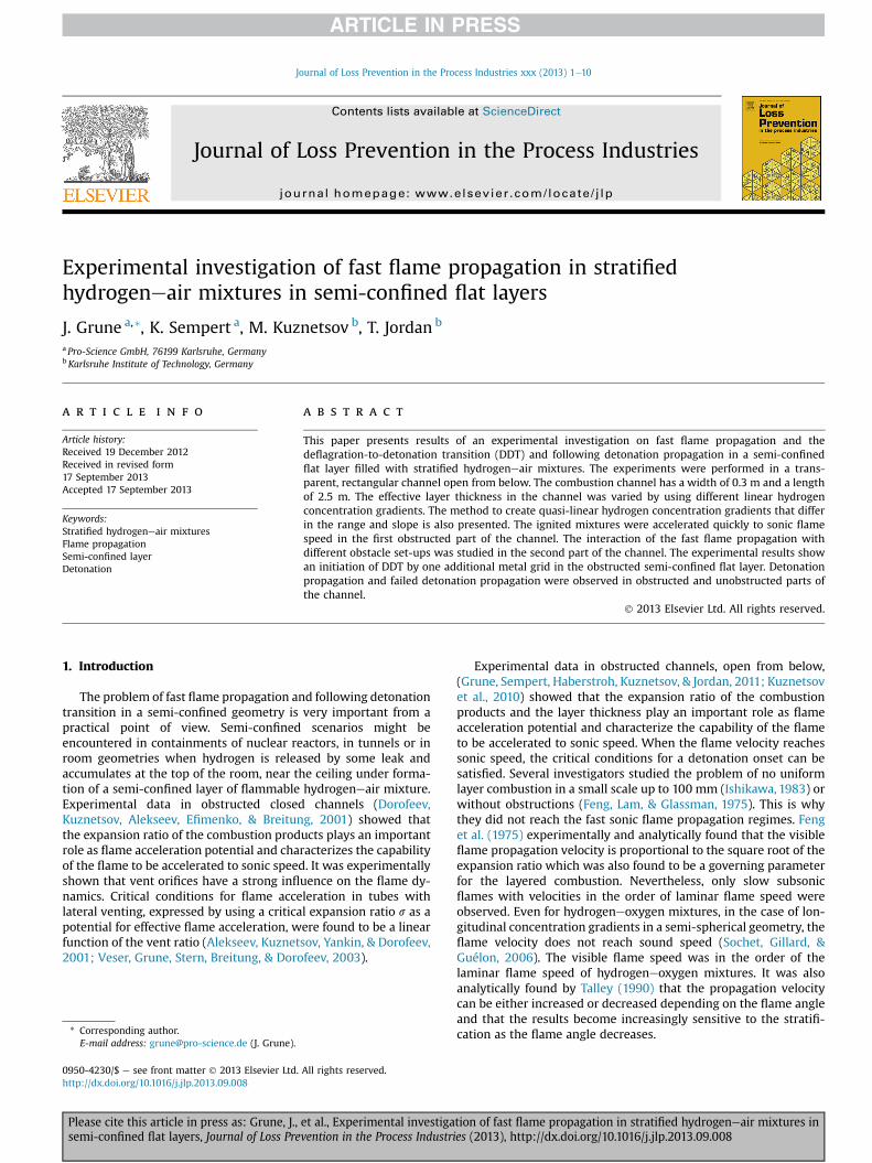
Experimental investigation of fast flame propagation in stratified hydrogeneair mixtures in semi-confined flat layers J. Grune a, * , K. Sempert a , M. Kuznetsov b , T. Jordan b a Pro-Science GmbH, 76199 Karlsruhe, Germany b Karlsruhe Institute of Technology, Germany article info Article history: Received 19 December 2012 Received in revised form 17 September 2013 Accepted 17 September 2013 Keywords: Stratified hydrogeneair mixtures Flame propagation Semi-confined layer Detonation abstract This paper presents results of an experimental investigation on fast flame propagation and the deflagration-to-detonation transition (DDT) and following detonation propagation in a semi-confined flat layer filled with stratified hydrogeneair mixtures. The experiments were performed in a trans- parent, rectangular channel open from below. The combustion channel has a width of 0.3 m and a length of 2.5 m. The effective layer thickness in the channel was varied by using different linear hydrogen concentration gradients. The method to create quasi-linear hydrogen concentration gradients that differ in the range and slope is also presented. The ignited mixtures were accelerated quickly to sonic flame speed in the first obstructed part of the channel. The interaction of the fast flame propagation with different obstacle set-ups was studied in the second part of the channel. The experimental results show an initiation of DDT by one additional metal grid in the obstructed semi-confined flat layer. Detonation propagation and failed detonation propagation were observed in obstructed and unobstructed parts of the channel. Ó 2013 Elsevier Ltd. All rights reserved. 1. Introduction The problem of fast flame propagation and following detonation transition in a semi-confined geometry is very important from a practical point of view. Semi-confined scenarios might be encountered in containments of nuclear reactors, in tunnels or in room geometries when hydrogen is released by some leak and accumulates at the top of the room, near the ceiling under forma- tion of a semi-confined layer of flammable hydrogeneair mixture. Experimental data in obstructed closed channels (Dorofeev, Kuznetsov, Alekseev, Efimenko, & Breitung, 2001) showed that the expansion ratio of the combustion products plays an important role as flame acceleration potential and characterizes the capability of the flame to be accelerated to sonic speed. It was experimentally shown that vent orifices have a strong influence on the flame dy- namics. Critical conditions for flame acceleration in tubes with lateral venting, expressed by using a critical expansion ratio s as a potential for effective flame acceleration, were found to be a linear function of the vent ratio (Alekseev, Kuznetsov, Yankin, & Dorofeev, 2001; Veser, Grune, Stern, Breitung, & Dorofeev, 2003). Experimental data in obstructed channels, open from below, (Grune, Sempert, Haberstroh, Kuznetsov, & Jordan, 2011; Kuznetsov et al., 2010) showed that the expansion ratio of the combustion products and the layer thickness play an important role as flame acceleration potential and characterize the capability of the flame to be accelerated to sonic speed. When the flame velocity reaches sonic speed, the critical conditions for a detonation onset can be satisfied. Several investigators studied the problem of no uniform layer combustion in a small scale up to 100 mm (Ishikawa, 1983) or without obstructions (Feng, Lam, & Glassman, 1975). This is why they did not reach the fast sonic flame propagation regimes. Feng et al. (1975) experimentally and analytically found that the visible flame propagation velocity is proportional to the square root of the expansion ratio which was also found to be a governing parameter for the layered combustion. Nevertheless, only slow subsonic flames with velocities in the order of laminar flame speed were observed. Even for hydrogeneoxygen mixtures, in the case of lon- gitudinal concentration gradients in a semi-spherical geometry, the flame velocity does not reach sound speed (Sochet, Gillard, & Guélon, 2006). The visible flame speed was in the order of the laminar flame speed of hydrogeneoxygen mixtures. It was also analytically found by Talley (1990) that the propagation velocity can be either increased or decreased depending on the flame angle and that the results become increasingly sensitive to the stratifi- cation as the flame angle decreases. * Corresponding author. E-mail address: [email protected] (J. Grune). Contents lists available at ScienceDirect Journal of Loss Prevention in the Process Industries journal homepage: www.elsevier.com/locate/jlp 0950-4230/$ e see front matter Ó 2013 Elsevier Ltd. All rights reserved. http://dx.doi.org/10.1016/j.jlp.2013.09.008 Journal of Loss Prevention in the Process Industries xxx (2013) 1e10 Please cite this article in press as: Grune, J., et al., Experimental investigation of fast flame propagation in stratified hydrogeneair mixtures in semi-confined flat layers, Journal of Loss Prevention in the Process Industries (2013), http://dx.doi.org/10.1016/j.jlp.2013.09.008
Transcript of Experimental investigation of fast flame propagation in stratified hydrogen–air mixtures in...
lable at ScienceDirect
Journal of Loss Prevention in the Process Industries xxx (2013) 1e10
Contents lists avai
Journal of Loss Prevention in the Process Industries
journal homepage: www.elsevier .com/locate/ j lp
Experimental investigation of fast flame propagation in stratifiedhydrogeneair mixtures in semi-confined flat layers
J. Grune a,*, K. Sempert a, M. Kuznetsov b, T. Jordan b
a Pro-Science GmbH, 76199 Karlsruhe, GermanybKarlsruhe Institute of Technology, Germany
a r t i c l e i n f o
Article history:Received 19 December 2012Received in revised form17 September 2013Accepted 17 September 2013
Keywords:Stratified hydrogeneair mixturesFlame propagationSemi-confined layerDetonation
* Corresponding author.E-mail address: [email protected] (J. Grune).
0950-4230/$ e see front matter � 2013 Elsevier Ltd.http://dx.doi.org/10.1016/j.jlp.2013.09.008
Please cite this article in press as: Grune, J.,semi-confined flat layers, Journal of Loss Pre
a b s t r a c t
This paper presents results of an experimental investigation on fast flame propagation and thedeflagration-to-detonation transition (DDT) and following detonation propagation in a semi-confinedflat layer filled with stratified hydrogeneair mixtures. The experiments were performed in a trans-parent, rectangular channel open from below. The combustion channel has a width of 0.3 m and a lengthof 2.5 m. The effective layer thickness in the channel was varied by using different linear hydrogenconcentration gradients. The method to create quasi-linear hydrogen concentration gradients that differin the range and slope is also presented. The ignited mixtures were accelerated quickly to sonic flamespeed in the first obstructed part of the channel. The interaction of the fast flame propagation withdifferent obstacle set-ups was studied in the second part of the channel. The experimental results showan initiation of DDT by one additional metal grid in the obstructed semi-confined flat layer. Detonationpropagation and failed detonation propagation were observed in obstructed and unobstructed parts ofthe channel.
� 2013 Elsevier Ltd. All rights reserved.
1. Introduction
The problem of fast flame propagation and following detonationtransition in a semi-confined geometry is very important from apractical point of view. Semi-confined scenarios might beencountered in containments of nuclear reactors, in tunnels or inroom geometries when hydrogen is released by some leak andaccumulates at the top of the room, near the ceiling under forma-tion of a semi-confined layer of flammable hydrogeneair mixture.Experimental data in obstructed closed channels (Dorofeev,Kuznetsov, Alekseev, Efimenko, & Breitung, 2001) showed thatthe expansion ratio of the combustion products plays an importantrole as flame acceleration potential and characterizes the capabilityof the flame to be accelerated to sonic speed. It was experimentallyshown that vent orifices have a strong influence on the flame dy-namics. Critical conditions for flame acceleration in tubes withlateral venting, expressed by using a critical expansion ratio s as apotential for effective flame acceleration, were found to be a linearfunction of the vent ratio (Alekseev, Kuznetsov, Yankin, & Dorofeev,2001; Veser, Grune, Stern, Breitung, & Dorofeev, 2003).
All rights reserved.
et al., Experimental investigavention in the Process Industri
Experimental data in obstructed channels, open from below,(Grune, Sempert, Haberstroh, Kuznetsov, & Jordan, 2011; Kuznetsovet al., 2010) showed that the expansion ratio of the combustionproducts and the layer thickness play an important role as flameacceleration potential and characterize the capability of the flameto be accelerated to sonic speed. When the flame velocity reachessonic speed, the critical conditions for a detonation onset can besatisfied. Several investigators studied the problem of no uniformlayer combustion in a small scale up to 100 mm (Ishikawa, 1983) orwithout obstructions (Feng, Lam, & Glassman, 1975). This is whythey did not reach the fast sonic flame propagation regimes. Fenget al. (1975) experimentally and analytically found that the visibleflame propagation velocity is proportional to the square root of theexpansion ratio which was also found to be a governing parameterfor the layered combustion. Nevertheless, only slow subsonicflames with velocities in the order of laminar flame speed wereobserved. Even for hydrogeneoxygen mixtures, in the case of lon-gitudinal concentration gradients in a semi-spherical geometry, theflame velocity does not reach sound speed (Sochet, Gillard, &Guélon, 2006). The visible flame speed was in the order of thelaminar flame speed of hydrogeneoxygen mixtures. It was alsoanalytically found by Talley (1990) that the propagation velocitycan be either increased or decreased depending on the flame angleand that the results become increasingly sensitive to the stratifi-cation as the flame angle decreases.
tion of fast flame propagation in stratified hydrogeneair mixtures ines (2013), http://dx.doi.org/10.1016/j.jlp.2013.09.008
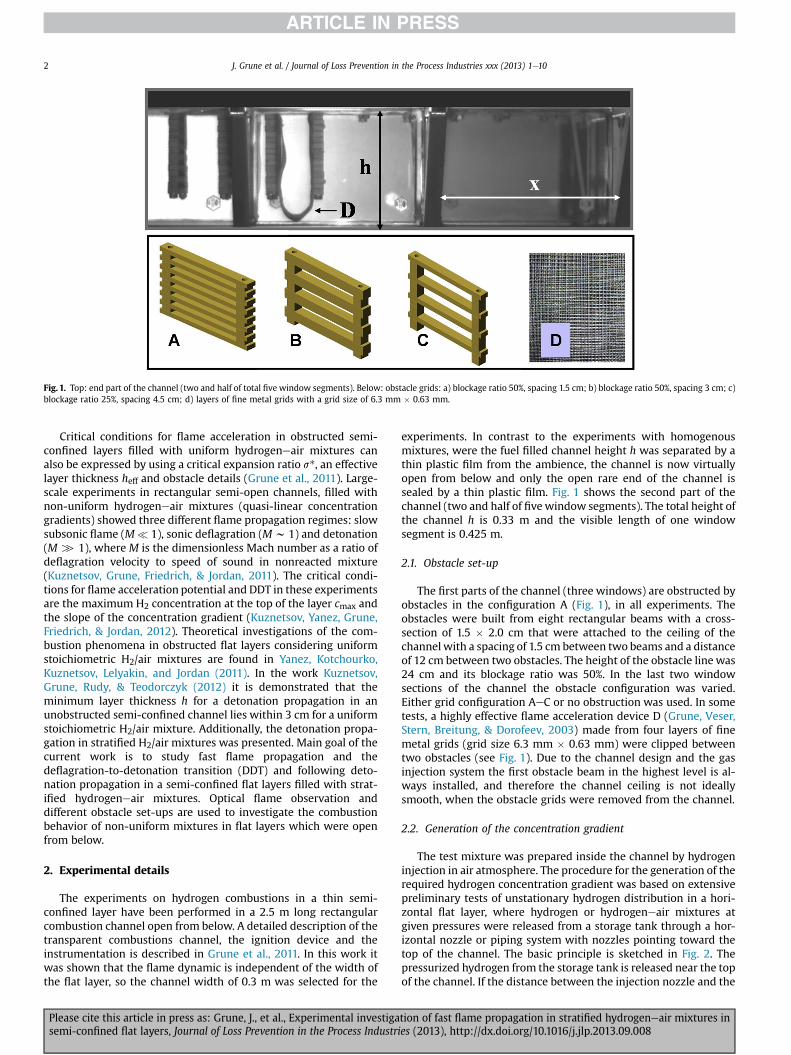
Fig. 1. Top: end part of the channel (two and half of total five window segments). Below: obstacle grids: a) blockage ratio 50%, spacing 1.5 cm; b) blockage ratio 50%, spacing 3 cm; c)blockage ratio 25%, spacing 4.5 cm; d) layers of fine metal grids with a grid size of 6.3 mm � 0.63 mm.
J. Grune et al. / Journal of Loss Prevention in the Process Industries xxx (2013) 1e102
Critical conditions for flame acceleration in obstructed semi-confined layers filled with uniform hydrogeneair mixtures canalso be expressed by using a critical expansion ratio s*, an effectivelayer thickness heff and obstacle details (Grune et al., 2011). Large-scale experiments in rectangular semi-open channels, filled withnon-uniform hydrogeneair mixtures (quasi-linear concentrationgradients) showed three different flame propagation regimes: slowsubsonic flame (M� 1), sonic deflagration (Mw 1) and detonation(M [ 1), where M is the dimensionless Mach number as a ratio ofdeflagration velocity to speed of sound in nonreacted mixture(Kuznetsov, Grune, Friedrich, & Jordan, 2011). The critical condi-tions for flame acceleration potential and DDT in these experimentsare the maximum H2 concentration at the top of the layer cmax andthe slope of the concentration gradient (Kuznetsov, Yanez, Grune,Friedrich, & Jordan, 2012). Theoretical investigations of the com-bustion phenomena in obstructed flat layers considering uniformstoichiometric H2/air mixtures are found in Yanez, Kotchourko,Kuznetsov, Lelyakin, and Jordan (2011). In the work Kuznetsov,Grune, Rudy, & Teodorczyk (2012) it is demonstrated that theminimum layer thickness h for a detonation propagation in anunobstructed semi-confined channel lies within 3 cm for a uniformstoichiometric H2/air mixture. Additionally, the detonation propa-gation in stratified H2/air mixtures was presented. Main goal of thecurrent work is to study fast flame propagation and thedeflagration-to-detonation transition (DDT) and following deto-nation propagation in a semi-confined flat layers filled with strat-ified hydrogeneair mixtures. Optical flame observation anddifferent obstacle set-ups are used to investigate the combustionbehavior of non-uniform mixtures in flat layers which were openfrom below.
2. Experimental details
The experiments on hydrogen combustions in a thin semi-confined layer have been performed in a 2.5 m long rectangularcombustion channel open from below. A detailed description of thetransparent combustions channel, the ignition device and theinstrumentation is described in Grune et al., 2011. In this work itwas shown that the flame dynamic is independent of the width ofthe flat layer, so the channel width of 0.3 m was selected for the
Please cite this article in press as: Grune, J., et al., Experimental investigasemi-confined flat layers, Journal of Loss Prevention in the Process Industri
experiments. In contrast to the experiments with homogenousmixtures, were the fuel filled channel height h was separated by athin plastic film from the ambience, the channel is now virtuallyopen from below and only the open rare end of the channel issealed by a thin plastic film. Fig. 1 shows the second part of thechannel (two and half of fivewindow segments). The total height ofthe channel h is 0.33 m and the visible length of one windowsegment is 0.425 m.
2.1. Obstacle set-up
The first parts of the channel (three windows) are obstructed byobstacles in the configuration A (Fig. 1), in all experiments. Theobstacles were built from eight rectangular beams with a cross-section of 1.5 � 2.0 cm that were attached to the ceiling of thechannel with a spacing of 1.5 cm between two beams and a distanceof 12 cm between two obstacles. The height of the obstacle line was24 cm and its blockage ratio was 50%. In the last two windowsections of the channel the obstacle configuration was varied.Either grid configuration AeC or no obstruction was used. In sometests, a highly effective flame acceleration device D (Grune, Veser,Stern, Breitung, & Dorofeev, 2003) made from four layers of finemetal grids (grid size 6.3 mm � 0.63 mm) were clipped betweentwo obstacles (see Fig. 1). Due to the channel design and the gasinjection system the first obstacle beam in the highest level is al-ways installed, and therefore the channel ceiling is not ideallysmooth, when the obstacle grids were removed from the channel.
2.2. Generation of the concentration gradient
The test mixture was prepared inside the channel by hydrogeninjection in air atmosphere. The procedure for the generation of therequired hydrogen concentration gradient was based on extensivepreliminary tests of unstationary hydrogen distribution in a hori-zontal flat layer, where hydrogen or hydrogeneair mixtures atgiven pressures were released from a storage tank through a hor-izontal nozzle or piping system with nozzles pointing toward thetop of the channel. The basic principle is sketched in Fig. 2. Thepressurized hydrogen from the storage tank is released near the topof the channel. If the distance between the injection nozzle and the
tion of fast flame propagation in stratified hydrogeneair mixtures ines (2013), http://dx.doi.org/10.1016/j.jlp.2013.09.008
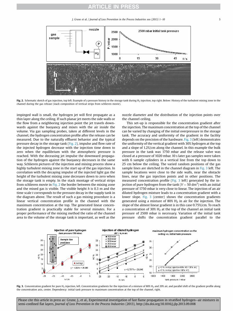
Fig. 2. Schematic sketch of gas injection, top left. Example of a pressure history in the storage tank during H2 injection, top right. Below: History of the turbulent mixing zone in thechannel during the gas release (stack composition of vertical strips from schlieren movie).
J. Grune et al. / Journal of Loss Prevention in the Process Industries xxx (2013) 1e10 3
impinged wall is small, the hydrogen jet will first propagate as athin layer along the ceiling. If such planar jet meets the side walls orthe flow from a neighboring injection point the jet travels down-wards against the buoyancy and mixes with the air inside thevolume. Via gas sampling probes, taken at different levels in thechannel, the hydrogen concentration profile after the release can bemeasured. Due to the naturally effluent behavior and the typicalpressure decay in the storage tank (Fig. 2), impulse and flow rate ofthe injected hydrogen decrease with the injection time down tozero when the equilibrium with the atmospheric pressure isreached. With the deceasing jet impulse the downward propaga-tion of the hydrogen against the buoyancy decreases in the sameway. Schlieren pictures of the injection and mixing process show ahighly turbulent mixing zone in the start up of the gas injection. Incorrelation with the decaying impulse of the injected light gas theheight of the turbulent mixing zone decreases down to zero whenthe storage tank is empty. In the stack montage of vertical stripsfrom schlieren movie in Fig. 2 the border between the mixing zoneand the mixed gas is visible. The visible height h is 0.3 m and thetime scale t corresponds to the pressure decay in the supply tank inthe diagram above. The result of such a gas mixing procedure is alinear vertical concentration profile in the channel with themaximum concentration at the top. The generated linear concen-tration gradient is practically stable for several minutes. For aproper performance of the mixing method the ratio of the channelarea to the volume of the storage tank is important, as well as the
Fig. 3. Concentration gradient for pure H2 injection, left. Concentration gradients for the injethe concentration axis, center. Dependency: initial tank pressure to maximum concentratio
Please cite this article in press as: Grune, J., et al., Experimental investigasemi-confined flat layers, Journal of Loss Prevention in the Process Industri
nozzle diameter and the distribution of the injection points overthe channel ceiling.
This set-up is responsible for the concentration gradient afterthe injection. Themaximum concentration at the top of the channelcan be varied by changing of the initial overpressure in the storagetank. The accuracy and uniformity of the gradient in the facilitydepends on the precision of the hardware. Fig. 3 (left) demonstratesthe uniformity of the vertical gradient with 30% hydrogen at the topand a slope of 1.2%/cm along the channel. In this example the bulkpressure in the tank was 1750 mbar and the release valve wasclosed at a pressure of 1020 mbar. 10 s later gas samples were takenwith 6 sample cylinders in a vertical line from the top down to25 cm below the ceiling. The varied random positions of the gassample lines are sketched in the channel diagram in Fig. 3 left. Thesample locations were close to the side walls, near the obstaclelines, near the gas injection points and in other positions. Themeasured concentration profile (Fig. 3 left) generated by the in-jection of pure hydrogen from the tank (V ¼ 50 dm3) with an initialpressure of 1750 mbar is very close to linear. The injection of an airdiluted hydrogen mixture leads to a concentration gradient with alower slope. Fig. 3 (center) shows the concentration gradientsgenerated using a mixture of 80% H2 in air for the injection. Theslope of the almost linear gradient is in this case 0.75%/cm. To reacha concentration of 30% H2 at the top of the channel an initial tankpressure of 2500 mbar is necessary. Variation of the initial tankpressure shifts the concentration gradient parallel to the
ction of a mixture of 80% H2 and 20% air, and parallel shift of the gradient profile alongn at the top of the channel, right.
tion of fast flame propagation in stratified hydrogeneair mixtures ines (2013), http://dx.doi.org/10.1016/j.jlp.2013.09.008

Fig. 4. Measured amplitudes of the combustion overpressure along the channel.
J. Grune et al. / Journal of Loss Prevention in the Process Industries xxx (2013) 1e104
concentration axis, allowing the controlling of the concentration atthe top of the channel. Fig. 3 (right) shows the non-linear de-pendency of the initial tank pressure and the maximum concen-tration for pure hydrogen and a mixture of 80% H2 in air. With thepresented turbulent gas mixing method it is possible to createalmost linear concentration gradients in flat layer channels whichare open from below. Based on the hardware set-up a maximumslope of the gradient generated by the injection of pure H2 is con-stant. Injection of diluted light gas leads to a decrease of thegradient. More examples of results for this method were presentedfor larger scale in Kuznetsov et al. (2012).
3. Experimental results
3.1. Flame propagation regimes
Due to the obstacle set-up in the first part of the channel (Type Ain Fig. 1) the flame accelerates here to sonic velocities after theignition in the first half of the channel. The plot in Fig. 4 shows themeasured amplitudes of the combustion overpressures for severalexperiments. In all tests the maximum overpressure is more than5 bar within a run up distance of 1 m, except for the test with thelowest concentration at the top (17% H2) and a gradient of 0.72%/cmwhich accelerates slowly and reaches combustion overpressure of5 bar and more at the end of the channel. For all other experimentsthe measured pressure amplitude on the first and second gauge arevery similar but on the third sensor a large scatter of the measuredamplitudes is observed. One accumulation of points lies between 8and 9 bar, while others reach pressure levels of more than 20 bar,which correspond to detonation pressures. Further details aredescribed in Section 3.3. Compared to experiments with uniformhydrogeneair in the same geometry the amount of flammablemixture to reach sonic flame speed is less for stratified mixtures.For uniform hydrogeneair mixture the critical concentration forthe development of a fast flame is 15% H2 for a layer thickness h of24 cm and 20% H2 for h ¼ 12 cm. Under the assumption of a lineargradient with a slope of 0.72%/cm and a H2 concentration at the topof 17% the layer thickness is 23.6 cm, but on this level the H2 con-centration is zero. With a given concentration gradient a decreaseof the maximum concentration automatically reduces the layerthickness of the combustible mixture, but both layer thickness andmixture reactivity influence the possibility for flame acceleration.The higher the gradient, the sharper is the border between the slowand the fast combustion regime, see examples for lower gradientslopes of 0.2, 0.3, and 0.6%/cm (Kuznetsov et al., 2012).
Please cite this article in press as: Grune, J., et al., Experimental investigasemi-confined flat layers, Journal of Loss Prevention in the Process Industri
3.2. Effective layer thickness
A linear correlation between the critical expansion ratio s* forfast flame propagation in a flat layer and the reciprocal layerthickness 1/h of uniform hydrogen/air mixtures was formulated inGrune et al. (2011) and Kuznetsov et al. (2010).
Kuznetsov et al. (2010) used a linear correlation (1) between thecritical expansion ratio s* and the reciprocal layer thickness 1/h andthe spacing between obstacles (s), s*0 is the critical expansion ratiofor closed tubes ðs*0 ¼ 3:75Þ (Dorofeev et al., 2001), while K is achannel typical linear constant.
s* ¼ s*0ð1þ K$s=hÞ (1)
Another formula (2) for the critical conditions for flame accelera-tion to sonic speed in a semi-confined layer of uniform hydrogeneair mixtures was formulated by taking into account the effectivelayer thickness heff for the horizontal flame propagation and thetypical flame geometries observed in channels which are open frombelow (3)
s* ¼ s*0 þ 35=heff ; (2)
h2eff ¼ hA � ð½BR�$sÞB (3)
where heff is the real thickness of the combustible mixture takenfrom high speed movies of the experiments; A ¼ 1.3 and B ¼ 1.1 areempirical coefficients; BR ¼ Abl/A0 ¼ n$b/h is the blockage ratio orthe ratio of blocked cross-section Abl to total area of the channel A0;n is the number of horizontal obstacle beams; b is the width of eachbeam; h is the thickness of the layer.
During the combustion of a linearly stratified mixture layer,with the maximum concentration at its top, the amount ofhydrogen mixture which is below the flammability limit can notinfluence the combustion process in a significant way. Fig. 5 showsthe visible flame propagation between two obstacle grids (Type A,Fig. 1).
The H2 concentration at the top is 25% and the gradient is 1.2%/cm. The profile of the gradient is sketchedwith a red line in the firstand fourth frame. The frame rate of this photo sequence is 27,000 f/s and the horizontal flame propagation between the two obstaclegrids is completed in 4 or 5 frames, so the average velocity isw700 m/s.
After the combustion of the complete flammable volume the hotgases propagate downwards to the unblocked venting area, and the
tion of fast flame propagation in stratified hydrogeneair mixtures ines (2013), http://dx.doi.org/10.1016/j.jlp.2013.09.008

Fig. 5. Fast flame propagation between two obstacle lines (Type A, Fig. 1). Red line: sketch of concentration line with profile from 25 to 0% H2. (For interpretation of the references tocolour in this figure legend, the reader is referred to the web version of this article.)
J. Grune et al. / Journal of Loss Prevention in the Process Industries xxx (2013) 1e10 5
leading horizontal flame crosses to the next obstacle spacing. Theflammability limit for horizontal flame propagation of hydrogen/airmixtures is equal to 6.5% (Kumar, 1985).
By using the flammable horizontal fraction of the channel downto the concentration of the linear gradient reached 6.5% as layerthickness h(6.5%) and the expansion ratio s of the mixture with themaximumH2 concentration at the top of the channel, the equations(2) and (3) can be used to separate the experimentally observedslow and fast combustion regimes.
Fig. 6 summarizes data from the small channel experimentspresented here and earlier work (Grune et al., 2011). Additionalexperimental data from the large-scale channel for uniform mix-tures (Kuznetsov et al., 2010) and mixtures with concentrationgradients (Kuznetsov et al., 2012) were also plotted in the diagram.Both combustion channels have open bottom sides and obstacles ingrid design. The main differences are the spacing between theobstacles, the layer thickness, the channel width and the scale.
3.3. Details of fast flame propagation and DDT
The study of fast flame propagation and the deflagration-to-detonation transition (DDT) with following detonation propaga-tion in semi-confined flat layer filled with stratified hydrogeneairmixtures is based on the high speed observation of the visible flamepropagation in the second part of the channel. Frame rates of morethan 45,000 f/s and an observed length of the channel of more than
Fig. 6. Critical conditions for an effective flame acceleration in uniform mixtures andmixtures with concentration gradients as function of the expansion ratio vs. reciprocaleffective layer thickness heff: sonic flames and detonations (solid points); subsonicflames (open points).
Please cite this article in press as: Grune, J., et al., Experimental investigasemi-confined flat layers, Journal of Loss Prevention in the Process Industri
1 m give a sufficient resolution for the investigation of the fastflame propagation.
Experimental data for uniform H2eair mixtures in obstructedchannels open from below (Grune et al., 2011; Kuznetsov et al.,2010) showed a wide concentration range in which flame propa-gation in sonic mode dominates. In small scale, with a layerthickness of h ¼ 0.12 m, the critical concentration for a fast flame is20% H2 in air. DDT events were only observed for stoichiometric H2/O2 mixtures less diluted with nitrogen than stoichiometric H2eairmixture (34% H2; 17% O2; 49% N2). In larger scale, with a layerthickness of h¼ 0.30m, the range stretches from 17 to 26% H2 in air.The energy and momentum losses through the vent area of thesemi-confined channel suppress the “piston effect” of the com-bustion products in the flame path inside the obstacles. Addition-ally the geometrical limitations of the obstacle spacing and the sizeof the obstacle orifice prevent DDT in these tests. Overdriven sonicflames in semi-confined layers propagate with relations in range ofthe speed of sound in the reactants (Mach number: M w 1), whichis two times slower than in closed channels (Mw 2). The followingchapters show some details of the overdriven sonic flame propa-gation and the onset of DDT in semi-confined flat layers filled withstratified hydrogeneair mixtures.
3.3.1. Fast flame propagationThe series of shadow picture (Fig. 7), taken from a high speed
movie, shows a sonic flame propagation between two obstacles in amixture with 25% H2 at the top of the channel and a gradient of1.2%/cm. A strong shock wave is followed by the turbulent reactionfront. The distance between the leading shock wave and the reac-tion front changes in dependence of the position to the obstacle.The leading shock wave can pass the obstacle beams with a negli-gible velocity loss. For uniform mixtures the leading shock wave isorientated vertically (Grune et al., 2011), while for the combustionof a gradient mixture the shock wave propagates in the form of thelinear concentration gradient with some specific angle.
The left diagram in Fig. 8 shows the measured visible flamevelocities for an overdriven fast deflagration in the section betweentwo obstacle grids, the average flame speed is w800 m/s. Directlyafter the flame has passed the obstacle’s spacing, the highest flamevelocities were observed. The comparison of velocity profiles fromexperiments with the same blockage ratio and mixture propertiesbut different obstacle spacing shows a higher top speed for thenarrow spacing. Meanwhile the difference of the average flamespeed is negligible. The right diagram in Fig. 8 shows visible flamevelocities for two sections between two obstacles grids withdifferent blockage ratios. The oscillation of the flame speeds for theobstacle type C (Fig. 1) with BR ¼ 25% is less than for the type B(Fig. 1) with BR ¼ 50%. The average flame speed with approx.800 m/s is similar for both obstacle set-ups. In the lower part ofFig. 8 the evolution of the leading flame profile between twoobstacle lines is illustrated in the picture series, taken from high
tion of fast flame propagation in stratified hydrogeneair mixtures ines (2013), http://dx.doi.org/10.1016/j.jlp.2013.09.008
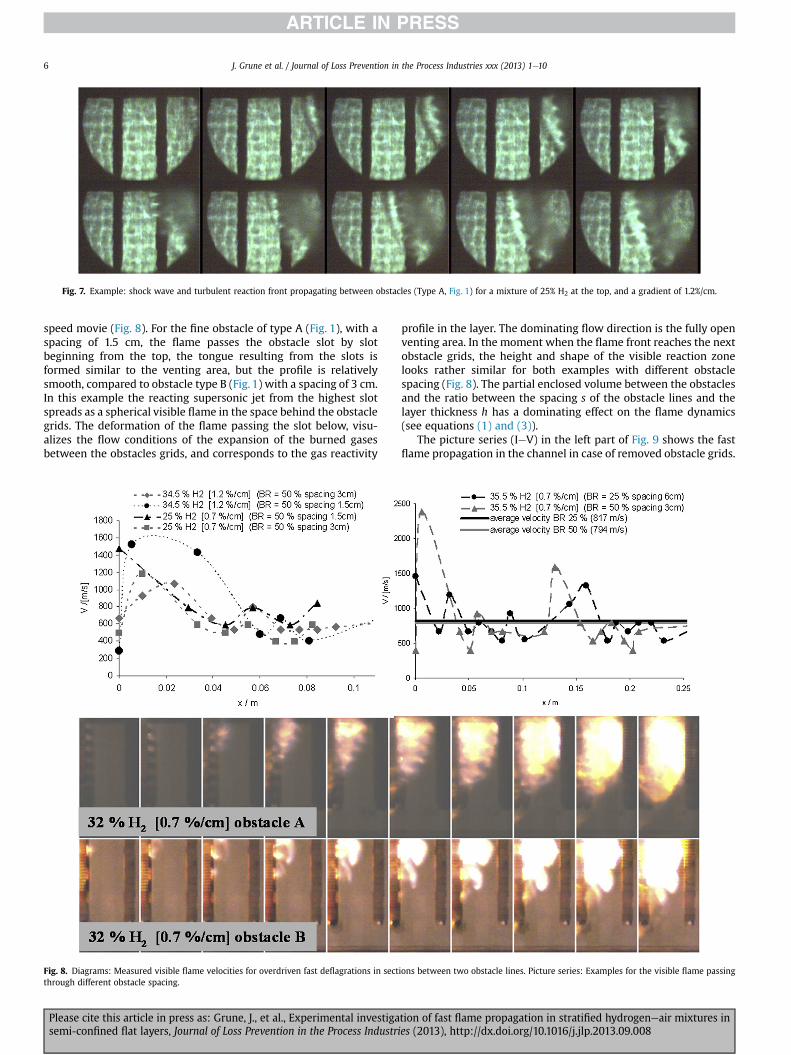
Fig. 7. Example: shock wave and turbulent reaction front propagating between obstacles (Type A, Fig. 1) for a mixture of 25% H2 at the top, and a gradient of 1.2%/cm.
J. Grune et al. / Journal of Loss Prevention in the Process Industries xxx (2013) 1e106
speed movie (Fig. 8). For the fine obstacle of type A (Fig. 1), with aspacing of 1.5 cm, the flame passes the obstacle slot by slotbeginning from the top, the tongue resulting from the slots isformed similar to the venting area, but the profile is relativelysmooth, compared to obstacle type B (Fig. 1) with a spacing of 3 cm.In this example the reacting supersonic jet from the highest slotspreads as a spherical visible flame in the space behind the obstaclegrids. The deformation of the flame passing the slot below, visu-alizes the flow conditions of the expansion of the burned gasesbetween the obstacles grids, and corresponds to the gas reactivity
Fig. 8. Diagrams: Measured visible flame velocities for overdriven fast deflagrations in sectthrough different obstacle spacing.
Please cite this article in press as: Grune, J., et al., Experimental investigasemi-confined flat layers, Journal of Loss Prevention in the Process Industri
profile in the layer. The dominating flow direction is the fully openventing area. In the moment when the flame front reaches the nextobstacle grids, the height and shape of the visible reaction zonelooks rather similar for both examples with different obstaclespacing (Fig. 8). The partial enclosed volume between the obstaclesand the ratio between the spacing s of the obstacle lines and thelayer thickness h has a dominating effect on the flame dynamics(see equations (1) and (3)).
The picture series (IeV) in the left part of Fig. 9 shows the fastflame propagation in the channel in case of removed obstacle grids.
ions between two obstacle lines. Picture series: Examples for the visible flame passing
tion of fast flame propagation in stratified hydrogeneair mixtures ines (2013), http://dx.doi.org/10.1016/j.jlp.2013.09.008

Fig. 9. Example of a fast flame propagation in the channel in case of removed obstacle lines.
Fig. 10. Stack montage of DDT: a) 32% H2 [0.7%/cm] obstacle type C (BR ¼ 25%); b) 32% H2 [0.7%/cm] obstacle type A (BR ¼ 50%); c) 28% H2 [0,7%/cm] obstacle type A (BR ¼ 50%); d)34.5% H2 [1.2%/cm] obstacle type A (BR ¼ 50%).
J. Grune et al. / Journal of Loss Prevention in the Process Industries xxx (2013) 1e10 7
Please cite this article in press as: Grune, J., et al., Experimental investigation of fast flame propagation in stratified hydrogeneair mixtures insemi-confined flat layers, Journal of Loss Prevention in the Process Industries (2013), http://dx.doi.org/10.1016/j.jlp.2013.09.008

Fig. 11. Measured visible flame velocities in the second part of the channel: Detonation propagation and failed detonation propagation (left). Propagation of a galloping detonationin the obstructed channel part (right).
J. Grune et al. / Journal of Loss Prevention in the Process Industries xxx (2013) 1e108
The flame travels as supersonic deflagration (I) in to a channel re-gion where the spacing s ¼ 0.48 m (three obstacle lines areremoved).
When the tip of the flame reaches the next obstacle line thetypical elliptical flame shape is formed (II). The leading flame frontnear the ceiling passes the next obstacle only at the ceiling (III). Dueto the partial enclosure between these obstacle lines s ¼ 0.12 m theflame accelerates downwards (IV) and propagates in flow andcounter-flow direction (V). The stack montage on the right sideof Fig. 9 illustrates the flame propagation in different levels of thechannel, the used stripes from the high speed movie are sketchedas stack A and stack B in (I). The stack montage A illustrates theflame propagation near the ceiling. The linearity of the leadingvisible flame in the timeedistance diagram indicates a stable flamevelocity ofw800m/s, the reflecting shockwaves from the obstaclesare clearly visualized. The stack montage B shows the horizontalflame propagation in a lower level of the channel. The initial su-personic deflagration speed decays to a lower constant speed in theunobstructed channel part, the reflected shock waves from nextobstacle line are also visible. Then the leading flame front travelsfrom both sides to an intersection point. The stack montages A andB illustrate that the vertical average velocity is the same for the two
Fig. 12. Detonation propagation and failed detonation propagation in an unobstructed part ob) Stack montage of DDT (32% H2 [0.7%/cm]); c) Stack montage of DDT with failed detonat
Please cite this article in press as: Grune, J., et al., Experimental investigasemi-confined flat layers, Journal of Loss Prevention in the Process Industri
levels of the example, but the flame path is different. In the un-obstructed channel part the fast deflagration propagates only in anarrow layer near the ceiling. With narrow obstacle lines moreflammable mixtures in lower concentration is included in the fastdeflagration combustion.
3.3.2. Initiation and propagation of detonationThe obstacle line types AeC (Fig. 1) were not able to transform a
supersonic deflagration into a detonation using uniform H2/airmixtures or linear concentration gradients formed from hydrogenand air. The suppressing effects are discussed in Grune et al. (2011).The installation of layers of fine metal grids with a grid size6.3� 0.63mm (see type D, Fig. 1) initiate DDT in a certainway if thevelocity of the flame is supersonic and the hydrogen concentrationis near 30%. Due to the clipped installation of the metal grid be-tween two obstacles the flame passes the grid structure two timesin horizontal direction and additionally the venting area is blockedby 15%. The stack montages aed (Fig. 10) illustrates the trans-formation of a supersonic deflagration into a detonation on the gridtype D (Fig. 1). The sudden break in the slope of the leading visibleflame front mark the DDT point, the transition can take place at thefirst flame-grid contact (a) or at the second (c) or it is not clearly
f the channel: a) Shape of the detonation front in the unobstructed part of the channel;ion propagation (28% H2 [0.7%/cm]).
tion of fast flame propagation in stratified hydrogeneair mixtures ines (2013), http://dx.doi.org/10.1016/j.jlp.2013.09.008
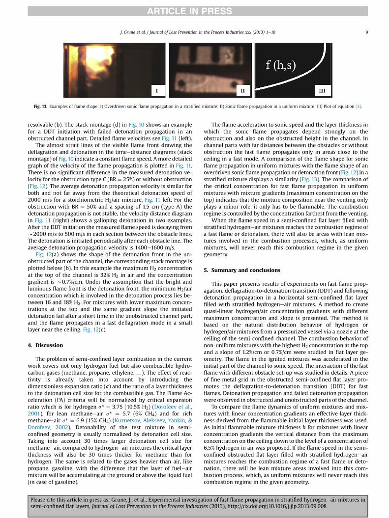
Fig. 13. Examples of flame shape: I) Overdriven sonic flame propagation in a stratified mixture; II) Sonic flame propagation in a uniform mixture; III) Plot of equation (3).
J. Grune et al. / Journal of Loss Prevention in the Process Industries xxx (2013) 1e10 9
resolvable (b). The stack montage (d) in Fig. 10 shows an examplefor a DDT initiation with failed detonation propagation in anobstructed channel part. Detailed flame velocities see Fig. 11 (left).
The almost strait lines of the visible flame front drawing thedeflagration and detonation in the timeedistance diagrams (stackmontage) of Fig.10 indicate a constant flame speed. Amore detailedgraph of the velocity of the flame propagation is plotted in Fig. 11.There is no significant difference in the measured detonation ve-locity for the obstruction type C (BR ¼ 25%) or without obstruction(Fig. 12). The average detonation propagation velocity is similar forboth and not far away from the theoretical detonation speed of2000 m/s for a stoichiometric H2/air mixture, Fig. 11 left. For theobstruction with BR ¼ 50% and a spacing of 1.5 cm (type A) thedetonation propagation is not stable, the velocity distance diagramin Fig. 11 (right) shows a galloping detonation in two examples.After the DDT initiation the measured flame speed is decaying fromw2000 m/s to 500 m/s in each section between the obstacle lines.The detonation is initiated periodically after each obstacle line. Theaverage detonation propagation velocity is 1400e1600 m/s.
Fig. 12(a) shows the shape of the detonation front in the un-obstructed part of the channel, the corresponding stack montage isplotted below (b). In this example the maximum H2 concentrationat the top of the channel is 32% H2 in air and the concentrationgradient is w0.7%/cm. Under the assumption that the bright andluminous flame front is the detonation front, the minimum H2/airconcentration which is involved in the detonation process lies be-tween 16 and 18% H2. For mixtures with lower maximum concen-trations at the top and the same gradient slope the initiateddetonation fail after a short time in the unobstructed channel part,and the flame propagates in a fast deflagration mode in a smalllayer near the ceiling, Fig. 12(c).
4. Discussion
The problem of semi-confined layer combustion in the currentwork covers not only hydrogen fuel but also combustible hydro-carbon gases (methane, propane, ethylene, .). The effect of reac-tivity is already taken into account by introducing thedimensionless expansion ratio (s) and the ratio of a layer thicknessto the detonation cell size for the combustible gas. The Flame Ac-celeration (FA) criteria will be normalized by critical expansionratio which is for hydrogen s* ¼ 3.75 (10.5% H2) (Dorofeev et al.,2001), for lean methaneeair s* ¼ 5.7 (6% CH4) and for richmethaneeair s* ¼ 6.9 (15% CH4) (Kuznetsov, Alekseev, Yankin, &Dorofeev, 2002). Detonability of the test mixture in semi-confined geometry is usually normalized by detonation cell size.Taking into account 30 times larger detonation cell size formethaneeair, compared to hydrogeneair mixtures the critical layerthickness will also be 30 times thicker for methane than forhydrogen. The same is related to the gases heavier than air, likepropane, gasoline, with the difference that the layer of fueleairmixture will be accumulating at the ground or above the liquid fuel(in case of gasoline).
Please cite this article in press as: Grune, J., et al., Experimental investigasemi-confined flat layers, Journal of Loss Prevention in the Process Industri
The flame acceleration to sonic speed and the layer thickness inwhich the sonic flame propagates depend strongly on theobstruction and also on the obstructed height in the channel. Inchannel parts with far distances between the obstacles or withoutobstruction the fast flame propagates only in areas close to theceiling in a fast mode. A comparison of the flame shape for sonicflame propagation in uniform mixtures with the flame shape of anoverdriven sonic flame propagation or detonation front (Fig.12) in astratified mixture displays a similarity (Fig. 13). The comparison ofthe critical concentration for fast flame propagation in uniformmixtures with mixture gradients (maximum concentration on thetop) indicates that the mixture composition near the venting onlyplays a minor role, it only has to be flammable. The combustionregime is controlled by the concentration farthest from the venting.
When the flame speed in a semi-confined flat layer filled withstratified hydrogeneair mixtures reaches the combustion regime ofa fast flame or detonation, there will also be areas with lean mix-tures involved in the combustion processes, which, as uniformmixtures, will never reach this combustion regime in the givengeometry.
5. Summary and conclusions
This paper presents results of experiments on fast flame prop-agation, deflagration-to-detonation transition (DDT) and followingdetonation propagation in a horizontal semi-confined flat layerfilled with stratified hydrogeneair mixtures. A method to createquasi-linear hydrogen/air concentration gradients with differentmaximum concentration and slope is presented. The method isbased on the natural distribution behavior of hydrogen orhydrogen/air mixtures from a pressurized vessel via a nozzle at theceiling of the semi-confined channel. The combustion behavior ofnon-uniformmixtures with the highest H2 concentration at the topand a slope of 1.2%/cm or 0.7%/cm were studied in flat layer ge-ometry. The flame in the ignited mixtures was accelerated in theinitial part of the channel to sonic speed. The interaction of the fastflame with different obstacle set-up was studied in details. A pieceof fine metal grid in the obstructed semi-confined flat layer pro-motes the deflagration-to-detonation transition (DDT) for fastflames. Detonation propagation and failed detonation propagationwere observed in obstructed and unobstructed parts of the channel.
To compare the flame dynamics of uniform mixtures and mix-tures with linear concentration gradients an effective layer thick-ness derived from the flammable initial layer thickness was used.As initial flammable mixture thickness h for mixtures with linearconcentration gradients the vertical distance from the maximumconcentration on the ceiling down to the level of a concentration of6.5% hydrogen in air was proposed. If the flame speed in the semi-confined obstructed flat layer filled with stratified hydrogeneairmixtures reaches the combustion regime of a fast flame or deto-nation, there will be lean mixture areas involved into this com-bustion process, which, as uniform mixtures will never reach thiscombustion regime in the given geometry.
tion of fast flame propagation in stratified hydrogeneair mixtures ines (2013), http://dx.doi.org/10.1016/j.jlp.2013.09.008
J. Grune et al. / Journal of Loss Prevention in the Process Industries xxx (2013) 1e1010
References
Alekseev, V. I., Kuznetsov, M. S., Yankin, Yu. G., & Dorofeev, S. B. (2001). Experi-mental study of flame acceleration and DDT under conditions of transverseventing. Journal of Loss Prevention in the Process Industries, 14(6), 591e596.
Dorofeev, S. B., Kuznetsov, M. S., Alekseev, V. I., Efimenko, A. A., & Breitung, W.(2001). Evaluation of limits for effective flame acceleration in hydrogen mix-tures. Journal of Loss Prevention in the Process Industries, 14, 583e589.
Feng, C. C., Lam, S. H., & Glassman, I. (1975). Flame propagation through layeredfuel-air mixtures. Combustion Science and Technology, 10(1), 59e71.
Grune, J., Veser, A., Stern, G., Breitung, W., & Dorofeev, S. (2003). Acceleration ofunconfined flames in congested areas, In Proceedings of 19th international col-loquium of the dynamics of explosions and reactive systems. Hakone, Japan.
Grune, J., Sempert, K., Haberstroh, H., Kuznetsov, M., & Jordan, T. (2011). Experi-mental investigation of hydrogeneair deflagrations and detonations in semi-confined flat layers. Journal of Loss Prevention in the Process Industries. ISSN:0950-4230. http://dx.doi.org/10.1016/j.jlp.2011.09.008.
Ishikawa, N. (1983). Combustion of stratified methane/air layers. Combustion Scienceand Technology, 30(1e6), 311e325.
Kumar, R. K. (1985). Flammability limits of hydrogen-oxygen-diluent mixture.Journal of Fire Sciences, 3, 245e262.
Kuznetsov, M., Alekseev, V., Yankin, Yu., & Dorofeev, S. (2002). Slow and fast def-lagrations in hydrocarbon-air mixtures. Combustion Science and Technology,174(5e6), 157e172.
Kuznetsov, M., Grune, J., Friedrich, A., & Jordan, T. (May 2e5, 2011). Combustionregimes in a stratified layer of hydrogeneair mixture, In International congresson advances in NPPs. Nice (France).
Please cite this article in press as: Grune, J., et al., Experimental investigasemi-confined flat layers, Journal of Loss Prevention in the Process Industri
Kuznetsov, M., Grune, J., Friedrich, A., Sempert, K., Breitung, W., & Jordan, T.(April 11e16, 2010). Hydrogen-air deflagration and detonation in a semi-confined flat layer, In 6th Internat. seminar on fire and explosion hazards.Leeds, GB.
Kuznetsov, M., Grune, J., Rudy, A., & Teodorczyk, A. (22e27 July 2012). Detonationinitiation and propagation in semi confined layer of hydrogen-air mixtures, InIX ISHPMIE international symposium on hazard, prevention and mitigation of in-dustrial explosions. Cracow, Poland.
Kuznetsov, M., Yanez, J., Grune, J., Friedrich, A., & Jordan, T. (June 24e28,2012). Hydrogen combustion in a flat semi-confined layer with respectto the Fukushima Daiichi Accident, In Proceedings of ICAPP ’12. Chicago,USA.
Sochet, I., Gillard, P., & Guélon, F. (2006). Effect of the concentration distribution onthe gaseous deflagration propagation in the case of H2/O2 mixture. Journal ofLoss Prevention in the Process Industries, 19(2e3), 250e262.
Talley, D. G. (1990). Some properties of nearly premixed laminar flame propagationalong weakly stratified layers in combustible gas mixtures. Combustion andFlame, 79(2), 141e150.
Veser, A., Grune, J., Stern, G., Breitung, W., & Dorofeev, S. (July 27eAugust 1, 2003).Flame acceleration in vented explosion tube, In 19th Internat. colloquium on thedynamics of explosions and reactive systems (ICDERS). Hakone, Japan, Proc. onCD-ROM Paper 183.
Yanez, J., Kotchourko, A., Kuznetsov, M., Lelyakin, A., & Jordan, T. (September 12e14,2011). Modeling of the flame acceleration in flat layer for hydrogen-air mix-tures, In Proc. of the 4th international conference on hydrogen safety (ICHS2011)(pp. 1e12). San Francisco, USA, paper r#201.
tion of fast flame propagation in stratified hydrogeneair mixtures ines (2013), http://dx.doi.org/10.1016/j.jlp.2013.09.008