Modelling the joint torques and loadings during squatting at the Smith machine
Upload
independentCategory
view
0download
0
Pergamon International Journal of Plasticity, Vol. 13, No. 1/2, pp. 87-109, 1997
© 1997 Elsevier Science Ltd Printed in Great Britain. All rights reserved
0749-6419/97 $17.00 + 0.00
PII: S0749-6419(97)00002-8
EXPERIMENTAL INVESTIGATION OF AN ANISOTROPY IN COPPER SUBJECTED TO PREDEFORMATION DUE TO
CONSTANT A N D MONOTONIC LOADINGS
Lech Dietrich and Zbigniew L. Kowalewski
Institute of Fundamental Technological Research P.A.Sc. 00-049 Warsaw, ul. ~;wi~tokrzyska 21, Poland
(Received in final revised form 15 August 1996)
Abstract--Experimental analysis of the plastic properties for both an aged pure copper and the same material subjected to various types of predeformation is presented. The analysis was made by studying the position in stress space and by determination of dimensions of the yield surfaces. The initial yield surface has been determined using the probing technique of a single specimen and this surface was used as the starting point for comparative studies of yield surfaces of the prestrained material. The material predeformations of the same magnitude were induced either by a creep process at elevated temperature or by monotonic loading at ambient temperature. After required values of plastic prestrain were attained, yield surfaces were determined by the same method as for the non.prestrained material. The anisotropic yield condition was used to create a least squares fit of the experimental data. © 1997 Elsevier Science Ltd
Key words: A. creep, B. metallic material, C. mechanical testing.
I. INTRODUCTION
The effect o f plastic prestrain induced in engineering materials due to industrial forming processes and during operat ion o f fabricated workpieces is a problem o f great importance, to which more and more space is devoted in professional papers.
Direct reasons for such a situation are, on the one hand, the fact that the plastic form- ing c o m m o n l y applied in the course o f the technological processes o f machine elements induces great plastic deformat ions in relatively short time and, on the other, the occur- rence o f gradual straining of structural components in manufac tured articles subjected to multiaxial loading and quite often to high temperatures.
As a result o f bo th these forms o f plastic prestrain, changes are induced in the basic mechanical ]properties such as yield limit, ultimate tensile stress, ductility and, moreover , they are the reasons for significant variations o f typical creep parameters as, for example, the min imum creep rate and t ime-to-rupture. In order to ensure safety o f devices subject to extremely hard operat ing conditions, it is necessary to carry out wide investigations o f a number o f engineering materials since, according to available experimental data obtained by many researchers, the behavior o f part icular materials after prestraining is often profoundly altered.
The effect o f predeformat ion on subsequent material behavior has been experimentally studied in well known laboratories using various loading programmes, e.g.:
1. Investigations o f the influence o f prior cold work on the creep process: Wilson (1973); Dyson and Rodgers (1974); Dyson et al. (1976); Tipler and Varma (1979);
87

88 L. Dietrich and Z. L. Kowalewski
Marlin et al. (1980); Rees (1981); Trampczyfiski (1982); Pandey et al. (1984); Waniewski (1984); Ohashi et al. (1986); Kowalewski (1991a, 1991b); Xia and Ellyin (1993) or on the plastic properties of a material: Szczepifiski (1963); Miastkowski and Szczepifiski (1965); Szczepifiski and Miastkowski (1968); Williams and Svens- son (1970, 1971); Hecker (1976); Helling et al. (1986); Szczepifiski et al. (1990);
2. Investigations of the effect of predeformation induced during creep on the subse- quent plastic properties of a material: Ohashi et al. (1983); Ikegami and Niitsu (1985); Winstone and Harrison (1986); Wu and Ho (1993).
In the first case, it has been found for some materials that plastic prestrain at room temperature can cause:
• an increase of the workpiece lifetime (Inconel MA 754, Marlin et al., 1980; Copper, Trampczyfiski, 1982),
• a decrease of the secondary creep rate observed under subsequent creep testing (Inconel MA 754, Marlin et al., 1980; Copper, Trampczyfiski, 1982; Copper, Waniewski, 1984; 316 Stainless Steel, Ohashi et al., 1986; Copper, Kowalewski, 1991a, 1991b),
• an increase of the yield limit observed under subsequent monotonic loading (Alu- minium Alloy, Szczepifiski, 1963; Brass, Miastkowski & Szczepifiski, 1965; 1100-F Aluminium, Williams and Svensson, 1970, 1971; Hecker, 1976).
For other materials such predeformation can cause a reverse effect, i.e.:
• a decrease of the lifetime under creep conditions (Inconel X-750, Pandey et al., 1984),
• an increase of the secondary creep rate observed under subsequent creep testing (Nimonic 80A, Dyson & Rodgers, 1974; Dyson et al., 1976),
• a decrease of the yield limit observed under subsequent monotonic loading (18G2A Low-Alloy Steel, Kowalewski & Sliwowski, 1997),
or it may have no influence whatsoever on the material properties during subsequent deformation (1/2Cr-1/2Mo-1/4V, Tipler & Varma, 1979).
It has been found in the majority of investigations mentioned in point 2 that creep prestrain has rather a beneficial effect on the subsequent plastic performance of tested materials (316 Stainless Steel, Ohashi et al., 1983; SUS 304 Stainless Steel, Ikegami & Niitsu, 1985; Nickel Superalloy Mar-M002, Winstone and Harrison, 1986; 304 Stainless Steel, Wu & Ho, 1993). Since in all these papers predeformation was induced by a creep process of a very short duration (few min or h), some important aspects of the creep phenomenon are not clearly reflected.
In this paper, both of the above-mentioned ways of prestraining have been applied. Initial deformation under creep was produced in typical conditions for such a process, i.e. at a stress level below the yield limit for the tested material at the temperature considered, and this distinguishes the paper from those earlier published.
II. E X P E R I M E N T A L DETAILS
II. 1. Mater ia l and specimen
The material used was 99.9% pure M1E copper (manufactured according to Polish Standards). After machining, all specimens were annealed for 2 h at 673 K and furnace-

Experimental investigation of an anisotropy in copper 89
cooled to achieve a uniform grain size and then all of them were aged at constant room temperature, by storing them for ten years at an underground laboratory. Just before work on the experimental project started, specimen microstructure was examined, mostly in order to determine the grain size of the tested material. The Neophot 21 metalographic microscope was used with a magnification of 200 and the representative picture is shown in Fig. 1. Grain-size measurements were performed using a display analyser equipped with a PC microcomputer together with the grain counting method of the Polish Standards No. PN-66/H-04507. The average grain size of tested copper was 0.058 mm. As shown in Fig. I, the material had a fine-grained structure with clearly outlined grain boundaries and with visible annealing twins.
The specimens used were thin-walled tubes of circular cross-section. Nominal dimen- sions were: gauge length 68 ram, outside diameter 17.5 mm, and wall thickness 0.75 mm. The specimen was so designed in order to be compatible with two different testing machines; a creep testing machine, and a biaxial INSTRON testing machine of model 1343. Protrusions limiting the gauge length were machined on the test-piece in order to fit a mechanical extensometer which transfers the displacement occurring during creep to a location ow:side the high temperature furnace where two transducers can precisely mea- sure displacements at ambient temperature. An engineering drawing of the specimen is shown in Fig. 2 . As is well known (Kowalewski et al., 1994, 1995), the extensometer ridges influence the deformation process of a material due to the circumferential rein- forcement; as a consequence, typical creep parameters such as minimum creep rate and time-to-rupture can differ from those determined from tests in which specimens without protrusions were used. In our case, however, the influence of protrusions was limited due to relatively long gauge length. Moreover, it has to be emphasized that the aim of creep tests (where protrusions were used) was only limited to the introduction of prior deformation of the material.
II.2, Testing devices
Two testing machines were required by the experimental project. The creep tests to induce initial deformations were performed on the high-temperature, combined loading,
Fig. 1. Microstructure of the tested copper.

90 L. Dietrich and Z. L. Kowalewski
020 O16
30
023.5
R1 \
O18
R2
O17.5 0.5-45 ° R1
i .
68
160
0 ~ F
i i
2
Fig. 2. Cross-section of the testpiece.
creep testing machine as described by Kowalewski (1987). The model 1343 INSTRON electrohydraulic, closed-loop, servo-controlled, biaxial testing machine enabling com- bined loading in tension-compression-torsion-reverse torsion was used in experiments performed in order to determine the shape and dimensions of yield surfaces. The maxi- mum axial and torsional load capacities are rated at + 100 kN and + 1000 Nm, respec- tively. Two separate servo-controller units connected to an HP 310 computer of the INSTRON loading system can independently apply controlled axial loads and torsional moments. The hydraulic pressure in the actuators comes from two servo-valves operated by servo-controllers provided with set-point control signals from the computer. A multi- ple analogue-to-digital converter feeds the HP310 computer with the signals of: axial dis- placement of machine piston, rotation of the grip fixture of a specimen, axial force, twisting moment, axial strain and torsional strain.
The axial force and the torque applied to the specimen were measured using load cells incorporated in the machine. The software, which had been specially developed for these tests, enabled the maintenance of constant effective strain rates during plastic loading and the resulting stress-strain responses were recorded by two independent acquisition units. The first acquisition unit was connected to the HP 310 control computer and for this reason had a rather limited ability to display current progress of an experiment run. The second acquisition unit operated independently of the control computer. It mainly com- prised a PEEKEL multi-channel measurement system from which the signals were fed back to a Hewlett-Packard Vectra 386 computer, thus enabling both direct on-line observations of the experimental results and also their saving onto the hard disk of the computer during each test.
11.3. Strain measurement
A mechanical extensometer and an electronic measurement system were used to mea- sure and record the strains of the specimens during the creep tests. The extensometer consisted of two coaxial tubes connected with the specimen by special grips. Two linear voltage displacement transducers (LVDT) for measuring the axial strains were connected to the lower ends of the tubes protruding outside the furnace. The creep testing device was equipped with a quartz clock for data recording at suitable time intervals. More details about this extensometer are included in a paper by Kowalewski (1987).
Experimental investigation of an anisotropy in copper 91
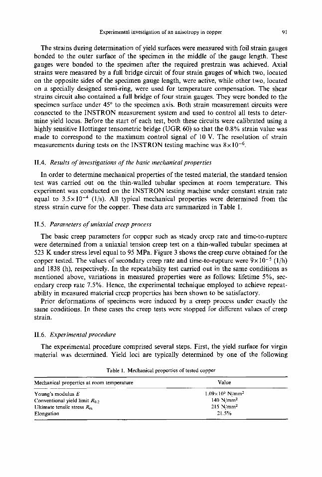
The strains during determination of yield surfaces were measured with foil strain gauges bonded to the outer surface of the specimen in the middle of the gauge length. These gauges were bonded to the specimen after the required prestrain was achieved. Axial strains were measured by a full bridge circuit of four strain gauges of which two, located on the opposite sides of the specimen gauge length, were active, while other two, located on a specially designed semi-ring, were used for temperature compensation. The shear strains circuit also contained a full bridge of four strain gauges. They were bonded to the specimen surface under 45 ° to the specimen axis. Both strain measurement circuits were connected to the INSTRON measurement system and used to control all tests to deter- mine yield locus. Before the start of each test, both these circuits were calibrated using a highly sensitive Hottinger tensometric bridge (UGR 60) so that the 0.8% strain value was made to correspond to the maximum control signal of 10 V. The resolution of strain measurements during tests on the INSTRON testing machine was 8x 10 -6.
11.4. Results of investigations of the basic mechanical properties
In order to determine mechanical properties of the tested material, the standard tension test was carried out on the thin-walled tubular specimen at room temperature. This experiment was conducted on the INSTRON testing machine under constant strain rate equal to 3.5x 10 -4 (I/s). All typical mechanical properties were determined from the stress-strain curve for the copper. These data are summarized in Table 1.
11.5. Parameters of uniaxial creep process
The basic creep parameters for copper such as steady creep rate and time-to-rupture were determined from a uniaxial tension creep test on a thin-walled tubular specimen at 523 K under stress level equal to 95 MPa. Figure 3 shows the creep curve obtained for the copper tested. The values of secondary creep rate and time-to-rupture were 9x 10 -5 (l/h) and 1838 (]a), respectively. In the repeatability test carried out in the same conditions as mentioned above, variations in measured properties were as follows: lifetime 5%, sec- ondary creep rate 7.5%. Hence, the experimental technique employed to achieve repeat- ability in measured material creep properties has been shown to be satisfactory.
Prior deformations of specimens were induced by a creep process under exactly the same conditions. In these cases the creep tests were stopped for different values of creep strain.
11.6. Experimental procedure
The experimental procedure comprised several steps. First, the yield surface for virgin material was determined. Yield loci are typically determined by one of the following
Table 1. Mechanical properties of tested copper
Mechanical properties at room temperature Value
Young's modulus E 1.09× 10⁵ N/mm 2 Conventional yield limit R0.2 140 N/mm 2 Ultimate tensile stress Rm 215 N/mm 2 Elongation 21.5%

92 L. Dietrich and Z. L. Kowalewski
(c) gxx
[%1 30
20
10
Oxx = 95 [ M P a ~ , / IT= 5 2 3 ~
. . . . . . . . . I . . . . . . . . . I . . . . . . . . . I . . . . . . . . . 0 500 1000 1500 2000
t [h]
Fig. 3. Creep curve of copper.
techniques (Ikegami, 1975; Hecker, 1976; Szczepifiski et al.., 1990; Dietrich et al., 1994):
(a) A number of specimens are loaded up to the plastic range along different stress directions. The yield stresses for a chosen definition are determined from each stress-strain curve and plotted in stress space to give the yield locus.
(b) One specimen is loaded in many different stress directions, each time until some measurable and limited plastic strain is observed. At each point it is unloaded and reloaded in a different direction until the entire yield locus is obtained. These directions differ from each other by a chosen angular increment, proceeding clock- wise or anti-clockwise in individual cases.
(c) One specimen is loaded in many different stress directions, each time until some measurable and limited plastic strain is observed. At each point it is unloaded and reloaded in a different direction until the entire yield locus is obtained. These directions differ from each other by an angle equal to 180 °, e.g. first loading takes place in the tension direction and next in the compression direc- tion, etc.
According to previous experiments, the first method gives results which are qualitatively best, since in this case the shape of the yield surface is not disturbed by the history of the previous probes performed on the same specimen in order to determine the other points of the yield locus. It has been found, however, that under certain conditions either (b) or (c) single-specimen methods can be successfully used to determine yield surface. In these methods, small plastic strains are needed to define yielding and they need a specific sequence of loading which should be the same for the whole experimental procedure. Moreover, the use of single-specimen methods overcomes the disadvantages of the first method, such as having to use a number of expensive specimens to determine each yield locus, and also having to deal with errors due to possible specimen-to-specimen varia- tions. These effects have been previously studied in detail by a number of researchers (Ikegami, 1975; Hecker, 1976; Dietrich et al., 1994). Taking into account these consid- erations and, furthermore, the time consumed by the creep tests while inducing specimen predeformation, the single specimen method described in point (c) was adopted for

Experimental investigation of an anisotropy in copper 93
determination of a yield surface. However, it has to be emphasized that method (b) gives the same quantitative results as (c) and, as a consequence, the differences between these two methods are really negligible for sufficiently small strain offsets. Both of them, with certain modifications, are commonly used by different investigators, e.g. method (b) - - Dietrich et al. (1994); Kowalewski and Sliwowski (1997) and method (c) - - Gupta and Lauert (1983); Cheng and Krempl (1991); Dietrich et al. (1994).
The definition of the yield point may have a remarkable effect on the resulting shape and dimensions of the yield surface. Generally, the yield point is defined by one of the following three points in the stress-strain diagram (Phillips et al., 1972; Phillips & Tang, 1972; Hecker, 1976):
• the point of the proportional limit, • the point by the back extrapolation, • the point by the proof stress.
Since in the case of the copper tested the yield point determined by the first two defini- tions was not clear-cut enough, the yield point was defined here by the proof stress throughout this experimental project.
In all tests for determination of a yield loci at the beginning of the loading phase of the specimen, Young's modulus was determined by the test controlling programme. Such calculations were carried out on the basis of experimental points obtained for the assumed stress limits. The loading of the specimen was stopped when the difference between the total effective strain and the elastic effective strain, calculated as the quotient of the effective stress and the earlier calculated Young's modulus, reached the chosen yield offset (in our case, it was 10-4). The difference in Young's modulus for the non-deformed and prestrained material, for the strain levels examined, was less than 8%.
Next, the strain control mode was changed to the stress control mode, and the unloading process was carried out until zero force and zero torque were reached. The entire loading and unloading processes were recorded. In the considered range of strain, the unloading process was linear for all directions in the stress space.
The experimental procedure comprised 16 successive steps for determining 16 points from the selected proportional (or radial) loading paths, as shown in Fig. 4. The angular spacing of ~Lhe radial paths was equal to 22.5 °. Starting from the origin, the specimen was first loaded in tension direction to point 1 where yielding occurred, as defined above, and then the specimen was completely unloaded and again loaded in reversed direction up to point 2 where again yielding occurred. The sequence so described was repeated until all 16 yield points were determined. In Fig. 4 the increasing numbers at the yield points indicate the loading sequence.
In all tests, the stress state components were defined by the commonly used relations for thin-walled tubes. Namely, the axial stress was expressed by the following formula:
4 . F tr~:, = (1)
( D o -
where F - axial force, Do - initial outside diameter measured within gauge length of the testpiece, d0 - initial inside diameter measured within gauge length of the testpiece, whereas the shear stress was defined in the form:

94 L. Dietrich and Z. L. Kowalewski
~f~ ~xy
~ .5 °
Fig. 4. Loading sequence for yield locus determination.
16. M s . Do - ( D 4 _ ( 2 )
where Ms - twisting moment. The magnitude of the effective stress in the stress state considered was expressed by the
well known relationship:
or e = ~O'x2 x -'1- 3 . ¢ (3)
while the effective strain was determined from the formula involving Poisson's ratio v:
3 2 Ee = E2x + (1 + V) 2 exy (4)
- shear strain. where: exx - axial strain, exy = 2 When v = 0.5 then this equation simplifies to the form:
1 2 Ee : E ~ x + ~ y (5)
The experimentally determined Poisson's ratio v for the copper tested was equal to 0.35 in the considered range of strain, i.e. up to 10 -4 . Thus, in all tests for yield locus determi- nation the eqn (4) was used to calculate effective strains.
In the second part of the experimental procedure, creep prestrain tests were performed on the creep testing machine under uniaxial tension stress equal to 95 MPa at elevated temperature (523 K). The creep process in each test was continued until an assumed value

Experimental investigation of an anisotropy in copper 95
of creep strain was attained and then stopped. The two chosen creep prestrain values were 5 and 15%, and this corresponded to the deformations obtained in a later phase of the primary creep and in an initial phase of the tertiary stage of creep, respectively. The determinatiion of the yield surface for both cases of creep predeformation was performed on the INSTRON testing machine with the use of the same procedure as previously applied for the non-prestrained material.
The third stage of the testing project comprised investigations during which prior deformations were induced by standard monotonic tension tests. These tests were carried out up to the same magnitudes of plastic prestrain as those in the creep process, i.e. 5 and 15%. The plastic prestrain due to monotonic loading and yield surface determinations was carried, out on the INSTRON testing machine.
IH. YIELD CONDITION
The yield condition represents a relation between stresses which are used to describe the transition of a body from an elastic state to a plastic range. In the case of isotropic materials, it has been shown that the Huber-Mises yield condition (Huber, 1904; Mises, 1913) in the form
So.S 0. = K 2 (6)
where S~ - stress deviator, and K - material constant, agrees well with experimental data. In practice, many engineering materials are not isotropic. In such cases, investigation of
a yield surface evolution is regarded as one of the most effective methods to study aniso- tropic properties of materials. Yield loci can be represented in a stress space by the experimental points determined on the basis of stress-strain diagrams for the magnitude of the effective strain assumed as a yield definition. These points determine the shape, dimensions and location of the yield surface. On the basis of the experimental points, all coefficients in a proposed anisotropic yield condition can be calculated using the least squares technique. Since numerous experimental data show that plastic anisotropy induced in metals by plastic forming processes is very complicated, it is difficult to expect that it can be described by a universal theory. All the forms of yield conditions discussed in many papers are based on certain simplifications and, therefore, they should be treated as approximate conditions only. In order to find the most accurate evaluation of aniso- tropic properties of a material, the yield condition used should possibly respect all the most impoJrtant phenomena associated with a plastic deformation, such as the Bauschin- ger effect, shift and rotation of the yield locus.
Mises (1928) proposed the general yield function for crystals being a quadratic func- tion with respect to stress components which contains 21 various coefficients of aniso- tropy. This function remains unchanged when the sign of all stress components is changed. It means that when using it, we cannot take into account the Bauschinger effect. If the Bauschinger effect in metals with deformation-induced anisotropy is to be accoun- ted for, linear terms with respect to stress components should be introduced in the yield condition. Szczepifiski (1993) has proposed, on the basis of the Mises anisotropic yield condition (Mises, 1928), a more general form of the yield condition for materials dis- playing the Bauschinger effect. This yield condition has been adopted in numerical calcu- lations pre,;ented in this paper since it reflects all effects mentioned above and, moreover,

96 L. Dietrich and Z. L. Kowalewski
it can be easily transformed into the other well known yield conditions, such as Hill's (Hill, 1956) or the yield condition proposed by Ota et al. (1959), under adequate assumptions.
Generally, the Mises anisotropic yield condition (Mises, 1928) in the form derived by Szczepifiski (1993), can be expressed by the following relationship:
J~fiij) = k l2( trxx - fiyy)2 ..1_ k23(fiyy - fizz) 2 + k31(fizz - f ixx) 2
+ 2rxy[kl6(fizz - trxx) + k26(fizz - - fiyy)] + 2ryz[k24(fixx - fiyy) + k34(fixx -- fizz)]
+ 2"rzx[k35(tryy - fizz) + kls(fiyy - trxx)] - 2k45. "gyz" T z x - - 2k56" rzx" "Cxy
-- 2k64" Txy " "(yz '[" k 4 4 . "E2z + k55. ~'2 x -[- k66. T2y -- b l2( f ixx - ~yy)
- b23(fiyy - fizz) - b31 (fizz - f ixx) + b44" ~'yz + b55 • Zzx -t- b66 • Zxy = 1
(7)
In the experimental project, tests were carried out providing only non-zero Oxx and rxy. When this is substituted into the relation (7), the yield condition is simplified as follows:
f(tr/j) = (k12 + k31)Cr2x - 2. k l6" "rxy" fixx + k66" Z2y + (b31 - bl2)trxx + b66" t'xy = 1 (8)
This expression represents the equation of a curve of a second order, usually written in the form:
Afi2xx + 2Bfixxrxy + C ~ y + 2Dfixx + 2Fzxy = 1 (9)
where coefficients A and D denote functions of yield limits for tension and compression, respectively. They can be expressed as follows:
1 1 1 A = Yxx.Zx--------x;2D- Yx~x Zxx (10)
where Yxx and Zxx are the yield limits for tension and for compression, respectively. The coefficients C and F are related to the shear yield limits obtained from tests under torsion and reverse torsion, respectively. They can be written in the following simple form:
1 1 1 C = . . , 2F (11)
Rxy " Rxy axy
where Rxy denotes the yield limit obtained under positive shear stress and Sxy denotes the yield limit obtained under negative shear stress.
The B coefficient, which is proportional to the rotation of a yield surface with respect to (fixx, rxy) co-ordinate system, has no such simple physical interpretation as the coefficients described above and it cannot be deduced from uniaxial tests. In order to find its value, it is necessary to carry out at least one test in a complex stress state.
The main dimensions of the ellipse for the anisotropic yield condition are expressed in the form of functions of parameters of a second order curve, i.e.:

Experimental investigation of an anisotropy in copper 97
where:
and:
co-ordinates of the ellipse centre:
B . F - C . D B . D - A . F ~ = ; ot~-- (12)
8 8
rotation angle of the ellipse axes with respect of (trxx, rxy) co-ordinate system:
1 2 - B ~ = ~ • arctan(~-Z---~)
major (a) and minor (b) ellipse semi-axes:
(13)
A . b = b' (14) a = a I. 8' .8
A = - A . C + 2 . B . D . F - C . D2 - A . FZ + B2; 8 = A . C - B 2 (15)
a ' = ~(A + C + v/(A - C) 2 + 4B 2)
b ' = ~(A + C - ~(A - C) 2 + 4B 2) (16)
The coefficients of the equation for the ellipse, to fit the experimental data, are calculated by the least squares method. Such a procedure enables the determination of all values of the coefficients in general form and, as a consequence, it provides information about the anisotropic properties of the tested material.
The yield condition for anisotropic materials in form (9) is determined by five material parameters.. From a geometrical point of view, they can be identified with the five ellipse parameters., i.e. the lengths of the axes, its centre co-ordinates and its rotation angle with respect to the co-ordinate system.
It has to be noted that, besides the quadratic yield functions, the non-quadratic yield functions have been also proposed, e.g. Gotoh (1977); Hill (1990); Barlat et al. (1988, 1991). Their yield conditions have been formulated in connection with the sheet-forming problems and are restricted to the special case of anisotropy. Such approaches are not considered in this paper.
IV. RESULTS OF INVESTIGATIONS
IV. 1. R e s u l t s f o r the virgin m a t e r i a l
Yield surfaces for the non-deformed pure copper determined for the three different offsets: eofy = 1 × 10 -5, 5× 10 -5, 1 × 10 -4 are shown in Fig. 5. Points in this figure represent experimental results while ellipses are obtained by the least squares evaluation of the A, B, C, D, F coefficients in eqn (9). Yield offset equal to 1 × 10 -4 corresponds to a maximum

98 L. Dietrich and Z. L. Kowalewski
value of the strain obtained in the yield surface determination tests. Two other offsets are taken in order to study the shape and dimensions of the surfaces at the lower plastic deformations. The ratios of the tension-compression and torsion-reverse torsion ellipse axes almost coincide with the ratio for the Huber-Mises ellipses for all chosen offsets. They are equal to 1.797, 1.737, 1.737 for e o f f = 1 × 10 -5, 5× 10 -5, 1 × 10 -4, respectively.
% (MPa)
150
100
50 ¸
0 -
- 5 0 -
-100
. . . . . . . . . . . . . . . . . . . . . . . . . . . . . . . . . . . . . . . . . . . . . . . . . . . . . . . . . . . . . . . . . . . . . . . . . . . . . . . . . . . . . . . . . . . . . . . . . . . . . . . . . . . . . . . i . . . . . . . . . . . . .
......... ° - S o f t = 1 x 1 0 "5
= - ~;off = 5 x10"5
e -~ ;o f f = l x 1 0 "4
-150 i i -150 -100 -50 0 50 100 150
O'xx (MPa)
Fig. 5. Experimental points and fitted yield surfaces for the virgin material.
150 T ~
(MPa) 1 O0 ............................. , ..........................................................................................................
'Oo -50
-100 o ~;off = l x 10-5 ] o Sorf = 5x10 "5 . . . . . . . . . . . . . . . . . . . . . . . . .
J ° So~ = l x 1 0 -4
-150 6 ' i -150 -1 0 -50 0 50 100 150
O'xx (MPa)
Fig. 6. Experimental points and fitted yield surfaces for the material prestrained up to 5% by creep.

Experimental investigation of an anisotropy in copper 99
IV.2. Results for the creep prestrained material
Figure 6 shows experimental points and yield surfaces obtained by the least squares fit of data for copper prestrained up to 5% at 523 K due to creep under uniaxial tension. The results for the same material prestrained to 15% are shown in Fig. 7. The yield offsets in both figures are the same as those for the virgin material, i.e. eoff = l x l 0 -5, 5x10 -s, 1 x l0 -4. In the case of prestraining up to 5%, the yield surfaces are nearly concentric whereas, fi)r creep prestraining up to 15%, the mid-points of the yield surfaces are shifted with respect to each other. Assuming as the reference point the ellipse centre for the lowest offset, the successive ellipse mid-points for greater offsets are shifted in the tension direc- tion, i.e. the direction of the initial plastic strain. The magnitudes of these translations are proportional to the values of yield offsets.
Some sraall rotations of yield surfaces are also observed, although they may be attrib- uted to the history of previous probes made in order to determine the yield locus rather than to the predeformation induced by creep. This conclusion comes from earlier experi- ments (Dietrich et al., 1994) in which the effect of probing sequence has been evaluated.
The relative position of the yield surfaces presented in Fig. 7 suggests that the advanced creep process induces remarkable anisotropy of the material, which is mainly observed in those directions which are coaxial with the predeformation. It is worth noting that such an effect is not detected for relatively small creep prestrains, (i.e. 5%).
IV.3. Restdts for the material prestrained due to monotonic loading
Similarly as in Section IV.2, the experimental points and fitted yield loci for three dif- ferent offsets are plotted in Figs 8 and 9 for the material prestrained by monotonic uni- axial tension up to 5 and 15%, respectively. As clearly shown in Fig. 8, the mutual
150 l:xy
( M P a ) 100
50
-50
-100
. . . . . . . . . . . . . . . . i . . . . £ } - - - 0 . . . . . .
x 0 ......... ~;o~ = 5x 10"5 ........................................................................................
Son = I x 10 "4
-150 , i -150 -100 -50 0 50 100 150
O'xx (MPa)
Fig. 7. Experimental points and fitted yield surfaces for the material prestrained up to 15% by creep.

100 L. Dietrich and Z. L. Kowalewski
location of the yield surfaces represented by the ellipses for various offsets is slightly unconcentric. Such an effect is much more visible for higher predeformation, i.e. 15% (cf. Fig. 9). The differences in yield surfaces obtained for various yield offsets provide a certain form of identification of the material anisotropy. However, in order to get an answer about the type of the induced anisotropy it is necessary to compare the results for the virgin and prestrained material.
150
(aPa ) 100
5O
0
-50
-100
-150
j
o ~;off = 1 x l O "5
[] E;of f = 5 x10 -5
• E:of f =1 x l O -4 !t t I I I
50 -100 -50 0 50 100 150
O'xx (MPa)
Fig. 8. Experimental points and fitted yield surfaces for the material prestrained up to 5% by monotonic tension.
T.xy 250 i
(MPa) 200 . . . . . . . . . . . . . . . . . . . . . . . . . . . . . . . . . . . . . . . . . . . . . . . . . . . . . . . . . . . . . . .
, , o . . . . . . . . . . . . . . . . . . . . . . ............... .......................... i
50
0
-50
- 1 O0
-150 I ° / E:off = l x 10 -5 ..... i ............... i . . . . . . . . . . . . i ............... i ...............
-2oo J / [] t;o. = 5 x lO -5 I J ' F
-250 ~ -250 -150 -50 0 50 150 250
O'xx (MPa)
Fig. 9. Experimental points and fitted yield surfaces for the material prestrained up to 15% by monotonic tension.

Experimental investigation of an anisotropy in copper 101
V. DISCUSSION OF THE EXPERIMENTAL RESULTS
In order to explain the influence of prior deformation on a subsequent yield surface, diagrams showing yield surfaces determined for different prestrains and different kinds of initial deformation are plotted. Figure 10 shows a comparison of the yield surfaces at the maximum offset taken, 1 x 10 -4, for the virgin copper and the same material prestrained in creep processes up to 5 and 15%. It is seen that, due to prior creep deformation at eleva- ted temperature, the material exhibits a hardening effect. In the case of 5% prestrain, this effect is relatively not so strong and has rather an isotropic character; there is no shift of the centre point of the yield surface of such a material, just a uniform increase of initial dimensions. Conversely, for the creep prestrain of 15%, besides the isotropic hardening, the material exhibits kinematic hardening expressed by the shift of the yield locus in the direction of the creep preloading path. In spite of the tertiary creep stage being reached, the degree of hardening for 15% prestrain is greater than that for 5%. The kinematic hardening: is not confirmed by a comparison of the yield surfaces obtained under the same conditions for smaller offset strain, 1 x 10 -5. In this case, the material mainly exhibits the isotropic hardening (Fig. 11).
Similar diagrams are presented in order to evaluate differences between yield surfaces for the virgin material and those for the material prestrained by means of monotonic tension at room temperature up to the exactly identical values of plastic deformation as in the creep, i.e. 5 and 15%. Figures 12 and 13 illustrate these yield surfaces for the 1 x 10 -5 and 1 x 10 -4 offsets, respectively. It can be seen that, for the smaller offset, regardless of the predeformation degree, the isotropic hardening effect seems to be dominant, whereas the kinematic one is rather weakly reflected. It is worth mentioning that the 15% pre- strained copper attains a much higher degree of hardening than the 5% one. This fact distinguishes these results from those of tests with creep-induced predeformation where the difference in hardening is not so remarkable. The last conclusion is also valid for the
%xy 150 i (MPa)
100 ................................................................................ ! .................... ............. 3 .......
-50
(1 - initial yield surface ) - 100 /2 - yield surface for the matedal prestrained
J | up to 5% by creep / 3 - yield surface for the material prestrained ( up to 15%bycreep
-150 ~, ~ i , , -150 -100 -5'0 0 50 100 150
~ (MPa)
Fig. 10. Comparison of the initial yield surface with yield loci for the creep prestrained material. The surfaces were obtained for 10 -4 yield offset.

102 L. Dietrich and Z. L. Kowalewski
1×10 -4 offset (Fig. 13). The results presented in Fig. 13 do not essentially differ from those shown in Fig. 12. However, in this case the kinematic hardening effect for the material plastically prestrained up to 15% is clearly displayed.
150
(MPa) 100
..................................................... i ........................... i "J ......................................................
i 3
-50
(1 - initial yield surface - 1 0 0 ...J2 - yield surface for the matedal prestrained J ..............................
| up to 5% by creep t3 - yield surface for the material prestrainea
up to 15% by creep
-150 i i , , .
-150 -1 O0 - 0 50 1 O0 150
~xx(MPa)
Fig. 11. Comparison of the initial yield surface with yield loci for the creep prestrained material. The surfaces were obtained for l0 -s yield offset.
Xxy (MPa)
150
00 i00 ...... i -50
1 - initial yield surface ] - 1 O0 2 - yield surface for the material plastically] ................. • .....................
prestrained up to 5% J i 3 - yield surface for the matedal plastically i i
- 150 prestrained up to 15% i
-150 -100 -50 0 50 100 150
O'XX (MPa)
Fig. 12. Comparison of the initial yield surface with yield loci for the monotonic tension prestrained material. The surfaces were obtained for l0 -5 yield offset.

Experimental investigation of an anisotropy in copper 103
Having available the experimental results for the virgin material and for both kinds of predeformed specimens, it seems worthwhile to present them together in one figure in order to identify the differences they exhibit for the same offset strain. Such comparative pictures are presented in Figures 14 and 15 for the 1 x l 0 - 4 offset. Figure 14 illustrates a comparison of the yield surface for a virgin material with the yield loci determined for the same material after predeformation up to 5% due to creep and monotonic loading.
'~xy
, 5 0 1 .............. i ..... i .............. i ....... i ........... i ........ i ............. i . . . . . . i ......... ~ . . . . . . . . . . . . . .
(MVa)
-150
-200
-250 , , , , , , t , n
-250 -200 -150-100-50 0 50 100 150 200 250
. f - initial yield surface ~ ........
/ 2 - yield s u r f a c e f o r t h e m a t e r i a l plastic.all | prestrained up to 5% plastica~J . . . . . . .
' / 3 - yield surface for the material ~. prestrained up to 15%
O'xx (MPa)
Fig. 13. Comparison of the initial yield surface with yield loci for the monotonic tension prestrained material. The surface,,; were obtained for 10 -4 yield offset.
'l~xy
(MPa)
200
150
100
50
0
-50
-100
-150
-200
i i3
1 2 - y ie ld sur face for the mater ia l p res t ra ined u p to 5 ....... ~ by creep .....
3 - sur face for t he mater ia l to 5 ~. by monotonic I o a d i n g y i e l d prestrained up %] t i i i i i J i /
-200 -150 -100 -50 0 50 100 150 200
O'xx (MPa)
Fig. 14. Comparison of the initial yield surface with yield loci for both kinds of prestraining of the material under the same prestrain magnitude (5%). The surfaces were obtained for 10 -4 yield offset.

104 L. Dietr ich and Z. L. Kowalewski
Figure 15 presents a similar comparison for 15% prestrain. An analysis of the shapes and dimensions of the yield surfaces implies the principal conclusion that the prior deforma- tion induced during monotonic loading at room temperature caused much greater hard- ening than prestrain of the same magnitude due to the long term creep at elevated temperature. From a physical point of view, such behaviour can be generally explained by studying deformation mechanisms related to the chosen predeformation processes. Prior deformation by means of monotonic tension at ambient temperature causes hardening in the tested copper, and this is related to a reduction of the mobile dislocation density in view of permanent or temporary halting of gliding dislocations by obstacles such as grain boundaries, precipitate particles, and other dislocations. In other words, increasing pre- strain reduces the density of mobile dislocations and, as a consequence, the degree of hardening is enhanced. In cases of prestraining due to creep, hardening is accompanied by thermally activated recovery and this causes activation of blocked dislocations by means of, for example, the dislocation climb mechanism. This latter mechanism is related to activation of additional glide planes by a temperature increase. In this stage of the analy- sis, it is worthwhile recalling that our creep tests have been performed at 523 K, which is lower than the recrystallization temperature of copper, and therefore there was no tem- perature-induced structural reconstruction and, as a consequence, recovery processes were not disturbed by the grain growth phenomenon. Gittus (1972) proposed a general rela- tionship between strain-induced immobilization and thermally activated recovery in the following form:
dp = (~tt)hdt + (O-~-P)rdt (17) ~t
where (~t)h, represents the rate at which hardening processes immobilize dislocations, ~p
(=-~.e'(p-po~)); (~7)r, represents the rate at which recovery processes remobilize disloca- tions, (= 7(P0-P)) P = mobile dislocation density, po~ = the asymptote towards which p
T'xy 250
(MPa) 2O0 . . . . . . . .
3
100
50
0
-50
-I00
-150 :1 - initial yield Surface 2 - yield surface for the material prestrained
up to 15% by creep -200 3 - yield surface for the matedalprestrained
up to !5% by monotonic load,rig -250 i i i i i i i i
- 2 5 0 - 2 0 0 - 1 5 0 - 1 0 0 - 5 0 0 50 100 150 200 250
O'xx(MPa)
Fig. 15. Comparison of the initial yield surface with yield loci for both kinds of prestraining of the material under the same prestrain magnitude (15%). The surfaces were obtained for 10 -4 yield offset.

Experimental investigation of an anisotropy in copper 105
falls as the strain increases; P0 = the maximum mobile dislocation density which occurs when t = 0.
Taking into account the above equation, it can be stated that hardening is much lower in the case of predeformations due to creep at elevated temperature than that induced in a standard tension test for the same prestrain magnitude since, in the former case, the test- ing material experiences a softening effect which remobilizes a part of the dislocations piled up on the barriers.
The evolutionary character of the yield surfaces for tested copper resulting from both kinds of prestraining exhibits mainly the isotropic hardening. The kinematic hardening effect is only observed for the maximum yield offset taken into account. Studying the results shown in Figs 14 and 15, it is easy to note that the hardening degree of the material previously subjected to creep changes in comparison to the hardening due to monotonic loading when the creep duration increases. The difference of the yield surface dimensions for both kinds of predeformation at its lower value of 5% is relatively small and is pro- duced by the thermal softening of the material during creep, a process which remobilizes dislocations halted on the barriers. A similar behaviour is demonstrated by the material prestrained to 15%, although in this case the tertiary stage of creep process was attained, for which the mutual balance between strain-hardening and recovery processes, as usually observed m the secondary creep period, was disturbed for the benefit of softening. This is most probably the reason why the difference of yield surface dimensions for both consid- ered predeformation types is much more marked for a higher prestrain and this is reflected in the comparison of yield surfaces presented in Figs 14 and 15. Graphical illustrations of the variatJions of yield surface dimensions as a function of the predeformation amount for both their kinds are shown in Figs 16-19. The variations of the ratio between the minor serai-axis of yield surface and that dimension for virgin material versus the pre- strain magnitude are plotted in Fig. 16. Curve 1 shows variations of this ratio for prestrain due to monotonic loading and curve 2 for creep prestrain. Fig. 17 shows variations con- cerning similarly defined ratios for the major semi-axis of yield surface. Notations in this figure are analogous to those of Fig. 16. Both of these figures demonstrate hardening for both kinds of predeformations. The degree of kinematic hardening, i.e. the shift of the
b/bo
2
exx [%] 0 5 10 15
Fig. 16. Variation of the b/bo ratio with the magnitude of predeformation, results for monotonic tension are denoted by 1 and those for creep by 2 (b and bo are the lengths of the minor semi-axis of the subsequent yield surface and of the initial yield surface, respectively).

106 L. Dietrich and Z. L. Kowalewski
a/a0 I
I
"0 5 10 15 &,lW
Fig. 17. Variation of the a/a,, ratio with the magnitude of predeformation. Results for monotonic tension are denoted by 1 and those for creep by 2 (a and a, are the lengths of the major semi-axis of the subsequent yield surface and that of the initial yield surface, respectively).
%3 lMP4
30.-
25--
20--
15.-
lO--
5--
I m : : % 1 1 o/ 0 5 10 15 &,[%I
Fig. 18. Variation of the shift of the ellipse centre with the magnitude of predeformation. Results for monotonic tension are denoted by 1 and those for creep by 2.
yield centre due to various ways of predeformation, is shown in Fig. 18. In all these fig- ures, the hardening effect for the copper prestrained in a standard tension test is signifi- cantly greater than the same effect obtained for the material initially subjected to high- temperature creep.
An interesting presentation of the results is shown in Fig. 19. It illustrates variations of the ratio between the major and minor axes of the yield surfaces as a function of the predeformation amount; 1 denotes the results for the copper prestrained due to mono- tonic loading, and 2 denotes the results for the material prestrained by creep. Further- more, the ratio which corresponds to the isotropic Huber-Mises yield condition is marked by a dashed line. It is seen that this condition is satisfied by the ratio of yield surface axes for no prestrain, while prestraining involves a remarkable anisotropy.

Experimental investigation of an anisotropy in copper 107
a/b
2.1
1.9
1.7
1.5
1.3
1.1 0.0
(
2 b ~ "
i I
a/b ratio for the Huber-Mises . . . . . . . . . . . y_i_el_d_ c_o_n aiti_o_n_ . . . . . . . . . .
2
1
I
0 5 10 15 ~xx [%]
Fig. 19. Variation of the a/b ratio with the magnitude of predeformation. Results for monotonic tension are denoted by 1 and those for creep by 2 (a and b are the lengths of the major and the minor semi-axis of the yield surface, respectively).
VI. CONCLUDING REMARKS
Experimental evaluation of the influence of predeformation induced in pure copper due to tension creep at elevated temperature and to monotonic tension at ambient tempera- ture on the shape and dimensions of yield surfaces has been reported in this paper. An analysis of the experimental results demonstrated that:
1. From an engineering point of view, the initial yield surface of the material is descri- bed with sufficient accuracy by the isotropic Huber-Mises yield condition. The ratio of major and minor axes of the ellipses is equal to 1.737 (1 x 10 -4) and the shift of this surface with respect to the origin of the Cartesian co-ordinate system is negligi- bly small. Even small prior plastic deformation induces anisotropy.
2. Plastic prestrain due to monotonic loading at ambient temperature causes a dispro- portionate increase of the yield surface axes in the direction coinciding with that of initial loading and in the direction perpendicular to the preloading. There is a drastic decrease of the ratio of the major and the minor axes of yield surface even for small plastic predeformations (5%) induced in the tension direction and essentially it does not undergo further variations for significantly greater plastic predeformations (15%). Prior deformation also causes a shift of the yield surface centre in the direc- tion of initial loading.
3. Plastiic prestrain due to constant stress creep at elevated temperature also causes disproportionate increase of yield surface axes for both directions and shift of the yield surface centre in the prior deformation direction. However, this is to a smaller degree than in the case of prior deformation of the same magnitude but induced by means of monotonic loading at room temperature. This is related to the additional high temperature exposure of the material during the creep process when carried out at elevated temperature.
4. In spite of the significant absolute variations between yield surface dimensions obtained after plastic prestrain of the same magnitude for both creep process and

108 L. Dietrich and Z. L. Kowalewski
monotonic loading, the ratio of the major and minor axes of yield surface tends to the same value at the sufficiently large plastic predeformation for both ways of initial prestraining.
Acknowledgements--The authors gratefully acknowledge support of the State Committee for Scientific Research (KBN) under grant 3 0154 91 01.
REFERENCES
Barlat, F., Lege, D. J. and Brem, J. C. (1991) A six-component yield function for anisotropic materials. Inter- national Journal of Plasticity 7, 693.
Barlat, F., Lian, J. and Baudelet, B. (1988) A yield function for orthotropic sheets under plane stress conditions. In Proc. 8th Int. Conf. Strength of Metals and Alloys, Vol. 1, pp. 283-288. Tampere, Finland. Pergamon Press, New York.
Cheng, S. and Krempl, E. (1991) Experimental determination of strain-induced anisotropy during nonpropor- tional straining of an AI/Mg alloy at room temperature. International Journal of Plasticity 7, 827.
Dietrich, L., Kiryk, R., Socha, G. and Sliwowski, M. (1994) Identification of Plastic Anisotropy of Aluminium Alloy, IFTR Reports 26, (in Polish).
Dyson, B. F., Loveday, M. S. and Rodgers, M. J. (1976) Grain boundary cavitation under various states of applied stress. Proceedings of theRoyal Society Set. A 349, 245.
Dyson, B. F. and Rodgers, M. J. (1974) Prestrain, cavitation and creep ductility. Metal Science 8, 261. Gittus, J. H. (1972) M ultiaxial mechanical equation of states for a work-hardening/recovery model of dislocation
creep. Philosophical Magazine 25, 1233. Gotoh, M. (1977) A theory of plastic anisotropy based on a yield function of fourth order (plane stress). Inter-
national Journal of Mechanical Sciences 19, 505. Gupta, N. K. and Lauert, H. A. (1983) A study of yield surface upon reversal of loading under biaxial stress.
Zeitschrift ffir Angewandte Mathematik und Mechanik 63, 497. Hecker, S. S. (1976) Experimental studies of yield phenomena in biaxially loaded metals. In Constitutive Equa-
tions in Viscoplasticity: Computational and Engineering Aspects, ed. Stricklin and Saczalski, Vol. 20, p. 1. The Winter Annual Meeting of The American Society of Mechanical Engineers, New York City, NY, ASME, AMD.
Helling, D. E., Miller, A. K. and Stout, M. G. (1986) An experimental investigation of the yield loci of 1100-0 aluminum, 70:30 brass, and an overaged 2024 aluminum alloy after various prestrains. Journal of Eng. Mat. Tech. 108, 313.
Hill, R. (1956) The Mathematical Theory of Plasticity, Oxford, Clarendon Press. Hill, R. (1990) Constitutive modelling of orthotropic plasticity in sheet metals. Journal of the Mechanics and
Physics of Solids 38, 405. Huber, M. T., (1904) Specific work of straining as a measure of material strengthening. Czasopismo techniczne,
Lwrw (in Polish). Ikegami, K. (1975) An historical perspective of the experimental study of subsequent yield surfaces for metal - -
Parts 1 & 2. Journal of the Society of Materials Science Japan 24, 491, and 709. Ikegami, K. and Niitsu, Y. (1985) Effect of creep prestrain on subsequent plastic deformation. International
Journal of Plasticity 1,331. Kowalewski, Z. (1991a) Creep behavior of copper under plane stress state. International Journal of Plasticity 7,
387. Kowalewski, Z. (1991b) The influence of deformation history on creep of pure copper. In Creep in Structures, ed.
M. Zyczkowski, p. 115. Proc. 4th IUTAM Symp., Cracow 1990, Springer-Verlag. Kowalewski, Z. L., Lin, J. and Hayhurst, D. R. (1994) Experimental and theoretical evaluation of a high-accu-
racy uni-axial creep testpiece with slit extensometer ridges. International Journal of Mechanical Sciences 36, 751.
Kowalewski, Z. (1987) The surface of constant rate of energy dissipation under creep and its experimental determination. Archives of Mechanics 39, 445.
Kowalewski, Z. L., Lin, J. and Hayhurst, D. R. (1995) Investigation of a high accuracy uni-axial creep testpiece with slit extensometer ridges. Archives of Mechanics 47, 2, 261.
Kowalewski, Z. L. and ~;liwowski, M. (1997) Effect of cyclic loading on the yield surface evolution of 18G2A low-alloy steel. International Journal of Mechanical Sciences, 39, 51.
Marlin, R. T., Cosandey, F. and Tien, J. K. (1980) The effect of predeformation on the creep and stress rupture of an oxide dispersion strengthened mechanical alloy. Metallurgical Transactions A 1 I A, ! 771.
Miastkowski, J. and Szczepifiski, W. (1965) An experimental study of yield surfaces of prestrained brass. Inter- national Journal of Solids and Structures 1, 189.

Experimental investigation of an anisotropy in copper 109
Mises, R. (1928) Mechanik der plastischen Form/inderung fiir Kristallen. Zeitschriftffir Angewandte Mathematik und Mechanik. !18, H3.
Mises, R. (1913) Mechanik der festen K6rper in plastischen Zustand, Grtingen Nachrichten. Ohashi, Y., Kawai, M. and Shimizu, H. (1983) Effects of prior creep on subsequent plasticity of type 316 stain-
less steel at elevated temperature. Journal of Engineering Materials and Technology 105, 257. Ohashi, Y., Kawai, M. and Momose, T. (1986) Effects of prior plasticity on subsequent creep of type 316 stain-
less steel at elevated temperature. Journal of Engineering Materials and Technology 108, 68. Ota, T., Shindo, A. and Fukuoka, H. (1959) A consideration on anisotropic yield criterion. Proc. 9th Jap. Nat.
Congr. Appl. Mech., p. 117. Pandey, M. C., Mukherjee, A. K. and Taplin, D. M. R. (1984) Prior deformation effects on creep and fracture in
Inconel Alloy X-750. Metallurgical Transactions A 15A, 1437. Phillips, A. and Tang, J.-L. (1972) The effect of loading path on the yield surface at elevated temperatures.
International Journal of Solids Structures 8, 463. Phillips, A., Liu, C. S. and Justusson, J. W. (1972) An experimental investigation of yield surfaces at elevated
temperatures. Acta Mechanica 14, 119. Rees, D. W. A. (1981) Effects of plastic prestrain on the creep of aluminium under biaxial stress. In Creep and
Fracture of Engineering Materials and Structures, ed. B. Wilshire, D. R. Owen, p. 559. Proceedings of the International Conference, Swansea, Pineridge Press.
Szczepifiski, W. (1993) On deformation-induced plastic anisotropy of sheet metals. Archives of Mechanics 45, 3. Szczepifiski, W., Dietrich, L. and Miastkowski, J. (1990) Plastic properties of metals, Part one. In Experimental
Methods in Mechanics of Solids, PWN, Elsevier. Szczepifiski, W. (1963) On the effect of plastic deformation on yield condition. Archives of Mechanics 2, 15, 275. Szczepifiski, W. and Miastkowski, J. (1968) An experimental study of the effect of the prestraining history on the
yield surfaces of an aluminium alloy. Journal of the Mechanics and Physics of Solids 16, 153. Tipler, H. J. and Varma, R. K. (1979) The effect of prior room temperature deformation on creep rupture and
cavitation of l/2Cr - 1/2Mo 1/4V steels of commercial and high purity, Vol. 2, p. 321. Thirdlnternational Conference on Mechanical Behaviour of Materials. Cambridge.
Trampczyfiski, W. A. (1982) The influence of cold work on the creep of copper under biaxial states of stress. A cta Metallurgica 30, 1035.
Waniewski, M. (1984) The influence of direction and value of plastic prestrain on steady-state creep rate using the comhined isotropic-kinematic hardening rule. Engineering Transactions 32, 523.
Williams, J. F. and Svensson, N. L. (1970) Effect of tensile prestrain on the yield locus of 1100 - F aluminium. Journal of Strain Analysis 5, 128.
Williams, J. F. and Svensson, N. L. (1971) Effect of torsional prestrain on the yield locus of 1100 - F aluminium. Journal of Strain Analysis 6, 263.
Wilson, R. N. (1973) The influence of 3% prestrain on the creep strength of A1-2.5% Cu-1.2% Mg alloys at 150 C. Journal of the Institute of Metals 101, 188.
Winstone, M R. and Harrison, G. F. (1986) Effects of overloads and creep on the yield surface of a nickel-based superalloy. In Techniques for Multi-Axial Creep Testing, ed. D. J. Gooch and I. M. How. Elsevier Applied
Science London and New York. Wu, H.-C. a~.d Ho, C.-C. (1993) Strain hardening of annealed 304 stainless steel by creep. Journal of Engineering
Materials and Technology 115, 345. Xia, Z. and Ellyin, F. (1993) An experimental study on the effect of prior plastic straining on creep behavior of
304 stainless steel. Journal of Engineering Materials and Technology 115, 200.
Copyright © 2022 FDOKUMEN