Experiences on developing computer vision hardware algorithms using Xilinx system generator
9
ffi ELSEVIER Available online at www.sciencedirect.com scrENcE @"rREcro Microprocessors and Microsystems 29 (2005) 411419 www.elsevier.com/locate/micpro Experiences on developing computer vision hardware algorithms using Xilinx system generator Ana Toledo Moreo, Pedro Navarro Lorente, F. Soto Valles, Juan Suardíaz Muro*, Carlos Fernández Andrés División de Sistemas e Ingeniería Electrónica (DSIE), universidad Potitécnica de Cartagena, Campus Muralla del Mar, s/n. Cartag.ena E-30202, Spain Received 20 October 2004; revised 8 November 2004; accepted 22 November 2004 Available online 2l December 2005 Abstract Computer vision is one of the areas where hardware-implemented algorithms perform clearly better than those implemented via softwa¡e. Digital designers have so far optimized their designs by means of application specific integrated circuits (ASICs) or digital signal processors (DSPs). However, nowadays they are increasingly using field programmable gate arrays (FPGAs), powerful hardware devices combining the main advantages of ASICs and DSPs with the possibility of re-programming, which make them very attractive devices for rapid prototyping. This paper shows how the Xilinx system generator (XSG) envi¡onment can be used to develop hardware-based computer vision algorithms from a system level approach, which makes it suitable for developing co-design environments. A 2004 Elsevier B.V. All rights reserved. Keywords: Computer vision; Co-design environments; FPGA-base<i hardware implementation; Matlab; Xilinx system generator MrcrcPROCESSORS AND MICROSYSTEMS 1. Introduction In the current computer vision systems, video cameras or some similar devices are used to transform incident light into data information that can be processed. A sampling process performed over a rectangular grid provides a picture matrix, the elements of which are related to that incident light [9,31]. Each element of this image matrix is called a 'picture element' or 'pixel', and its associated numeric value comes from a quantization process where incident energy is coded by using a given number of bits. Grey-Level images are very common in image proces- sing. These types of images use eight bits to code each pixel value, which results in 256 different possible shades ofgrey, ranging from 0 (black value) to 255 (white value). Fig. 1 shows an example of this kind of representation. * Corresponding author. Tel.: +34 68 32 53 80; fax: +34 68 32 53 45. E-mnil addresses.' [email protected] (A.T. Moreo), pedroj.navarro @upct.es (P.N. Lorente), [email protected] (F.S. Valles), juan. [email protected] (J.S. Muro), [email protected] (C.F. Andrés). 0l4l-9331/$ - see front matter @ 2004 Elsevier B.V. Atl rights reserved. doi: 10. I 016/j.micpro.2004. t 1.002 An image processing operation is commonly divided into four phases [3,9,22,3 l]: p r e - p roc e s s ing, s e g ment ation, feature extraction and recognition. The initial pre- processing phase seeks to enhance the quality of the original image by removing from the acquisition process such interfering elements as noise, unbalanced brightness, etc. This is followed by segmentation, a process during which images are separated from what could be considered the background into various elements with similar properties. Then feature extraction is performed on every detected object to reduce its information to a list of parameters or attributes (feature vectors) that are usually stored in memory. Finally, during Lhe recognition stage this list is used to generate a set of signals that constitute the upper level of processing, where a given meaning is assigned to every detected object. For example, a recognized string of digits could be associated with a telephone number, zip code, etc. depending on the type of processed information. From previous lines it can be inferred that it is usually along the processing stages when a huge amount of data has to be processed using simple and repetitive calculations, while subsequent steps will demand less data, but they will
Transcript of Experiences on developing computer vision hardware algorithms using Xilinx system generator
ffiELSEVIER
Available online at www.sciencedirect.com
scrENcE @"rREcro
Microprocessors and Microsystems 29 (2005) 411419www.elsevier.com/locate/micpro
Experiences on developing computer vision hardwarealgorithms using Xilinx system generator
Ana Toledo Moreo, Pedro Navarro Lorente, F. Soto Valles,Juan Suardíaz Muro*, Carlos Fernández Andrés
División de Sistemas e Ingeniería Electrónica (DSIE), universidad Potitécnica de Cartagena, Campus Muralla del Mar, s/n. Cartag.ena E-30202, Spain
Received 20 October 2004; revised 8 November 2004; accepted 22 November 2004
Available online 2l December 2005
Abstract
Computer vision is one of the areas where hardware-implemented algorithms perform clearly better than those implemented via softwa¡e.Digital designers have so far optimized their designs by means of application specific integrated circuits (ASICs) or digital signal processors(DSPs). However, nowadays they are increasingly using field programmable gate arrays (FPGAs), powerful hardware devices combining themain advantages of ASICs and DSPs with the possibility of re-programming, which make them very attractive devices for rapid prototyping.This paper shows how the Xilinx system generator (XSG) envi¡onment can be used to develop hardware-based computer vision algorithmsfrom a system level approach, which makes it suitable for developing co-design environments.A 2004 Elsevier B.V. All rights reserved.
Keywords: Computer vision; Co-design environments; FPGA-base<i hardware implementation; Matlab; Xilinx system generator
MrcrcPROCESSORS AND
MICROSYSTEMS
1. Introduction
In the current computer vision systems, video camerasor some similar devices are used to transform incidentlight into data information that can be processed. Asampling process performed over a rectangular gridprovides a picture matrix, the elements of which arerelated to that incident light [9,31]. Each element of thisimage matrix is called a 'picture element' or 'pixel', andits associated numeric value comes from a quantizationprocess where incident energy is coded by using a givennumber of bits.
Grey-Level images are very common in image proces-sing. These types of images use eight bits to code each pixelvalue, which results in 256 different possible shades ofgrey,ranging from 0 (black value) to 255 (white value). Fig. 1
shows an example of this kind of representation.
* Corresponding author. Tel.: +34 68 32 53 80; fax: +34 68 32 53 45.E-mnil addresses.' [email protected] (A.T. Moreo), pedroj.navarro
@upct.es (P.N. Lorente), [email protected] (F.S. Valles), [email protected] (J.S. Muro), [email protected] (C.F. Andrés).
0l4l-9331/$ - see front matter @ 2004 Elsevier B.V. Atl rights reserved.doi: 10. I 016/j.micpro.2004. t 1.002
An image processing operation is commonly dividedinto four phases [3,9,22,3 l]: p r e - p roc e s s ing, s e g ment ation,
feature extraction and recognition. The initial pre-processing phase seeks to enhance the quality of theoriginal image by removing from the acquisition processsuch interfering elements as noise, unbalanced brightness,etc. This is followed by segmentation, a process duringwhich images are separated from what could beconsidered the background into various elements withsimilar properties. Then feature extraction is performedon every detected object to reduce its information to a listof parameters or attributes (feature vectors) that areusually stored in memory. Finally, during Lhe recognitionstage this list is used to generate a set of signals thatconstitute the upper level of processing, where a givenmeaning is assigned to every detected object. Forexample, a recognized string of digits could be associatedwith a telephone number, zip code, etc. depending on thetype of processed information.
From previous lines it can be inferred that it is usuallyalong the processing stages when a huge amount of data has
to be processed using simple and repetitive calculations,while subsequent steps will demand less data, but they will

A.T. Moreo et al. / Microprocessors and Microsystems 29 (2005) 411419
Fig. 1. Grey-scale image representation
require much more complex algorithms to deal with allthese available data.
Designers of computer vision systems designers have ahistorical tendency to implement all these initial processing
stages by using hardware devices-mainly ASICs-like the
NOA processor used by Matrox in the Genesis Processing
Card [21]. However, more advanced stages-especiallythose of recognition-present complex computationalrequirements and they are therefore better implementedvia software routines.
For that reason, our current work focuses on developingprocessing algorithms by means of programmable logicaldevices. Field programmable gate affays (FPGAs) have
become increasingly popular because recent trends indicatea faster growth of its transistor density than even general-
purpose processors [6]. These electrical programmable
elements can be used as basic electronic devices toimplement low-level operations-where calculations are
simple, but a huge number of them are required-but they
also have potential enough to implement much more
complex systems dedicated to perform excessive time-consuming computation processes. Therefore, high logic
density plus and 'in system programmability' (ISP) offerdesigners a low cost and a powerful hardware tool for a
VLSI implementation of circuits with short lead times,
which turn FPGAs into a very useful design platform forrapid prototy ping U,16,23,301.
2. Main contributions of Xilinx system generator
When a system for quick complex computations isrequired, designers usually opt for hardware rather than
software based implementation, so an application specific
integrated circuit (ASIC), an application specif,c standardproduct (ASSP) or a digital signal processor (DSP) is
eventually chosen as the final implementation platform [10,19,261.
FPGA accelerators are very popular among the signal orimage processing community. Today's programmable logic
devices, especially FPGAs, present logical capacity and
potential performance enough to implement efflcientalgorithms that had hitherto been confined to the former.
Latest generations FPGAs compute more than 160 billionmultiplication and accumulation (MAC) operations per
second. These types of calculations are mainly presented as
a repetitive and typical spatial convolution computation in a
large number of computer vision algorithms. Such calcu-
lation usually requires image exploration with a convolution
mask in order to generate an output for each image pixel
consisting in a linear combination (multiplication and
additions) of the grey-scale values of its surrounding pixels
(Fie. 2).
In short, FPGA-based configurable computing machines
(CCMs) have emerged as an attractive alternative to high-
performance embedded computing. CCMs retain a general-
purpose nature, yet can be configured to offer a degree ofperformance which rivals application-specific hardware [6].A single CCM platform can be quickly reconfigured to
implement such a vast spectrum of different operations as
convolutions t37), a two-dimensional Fourier transform
[36], or even control-driven processing. CCMs are typically
characterized by high-capacity data paths and program-
mable interconnections among processing elements (PEs).
Historical CCM examples are Splash 2 [2], SONIC [11],PARTS [38] and Spyder [4]. Other interesting applications
in computer vision and image processing have already been
used to accelerate real-time point tracking Í291, real-time
image processing [15], medical image processing [41], 3D
Response: R = l¡r,' z, +tu¡'e¡ + ... +lf¡ü' E¡
{Ut lnt: !11¡
I,fil¡ Ws lñlE
Wr lik UI,
Fig. 2. Response of convolution masks
A.T. Moreo et al. / Microprocessors and Microsystems 29 (2005) 4ll-419 413
processing [24), video surveillance [17], patter recognition[20] and neural networks [8]. Future seems to be promisingfor this type of devices: new FPGAs families arisefrequently and they can also take advantage ofthe presenceof the intellectual property (IP) modules, consisting of a setof optimized hardware libraries which implement complexprocedures like Fourier transforms, FIR filters or evenmicrocontrollers and PCI bus controllers.
Although development tools for FPGA-based designsare now very powerful, the task of describing a complexsystem, which should be hardware implemented is still avery hard one. As Nayak [23], from AccelChip Inc.,affirms: '...since FPGAs are normally used for appli-cations with tremendous time to market constraints, thereis a need for more mature design tools. Although designtools exist which take the VHDL description of thehardware and generate bitstream, a current challenge inthis field is to design a highJevel synthesis (HLS) rool,which would allow designers to enter designs at a muchhigher level of abstraction. These HLS tools would takethe algorithmic description of the required hardwaretogether with cerlain area and performance requirementsof the designer, and perform an exploration of the designspace to output the hardware which meets the designer'sspecifications'.
To sum up, it would be very helpful-at least fordesigning hardware processing computer vision systems-to have similar specification languages to those used insoftware engineering because these types of language mayoffer very interesting features, such as:
(a) Ease of description of entangled concepts asconcurrence, synchronization, temporary models,structural descriptions, etc. all very common inhardware systems.
(b) Analytical power, related to the formal definition of thelanguage (mainly at a semantic level) and hence to itsability, when it is applied in some developmentenvironments, to analyse, transform and verify.
(c) Utilization cost, calculated by weighting several selec-tion criteria such as simplicity, availability of develop-ing tools or standardization level.
As a result, many languages for hardware specificationhave emerged in the last few years. C/C** is the mostpopular target language for implementing extendedlanguage variations capable of describing hardwareelements fl,27,28,351.
The most imporlant of these are listed below.
. System C Í25,34) consists ofa standardized proposal forhardware/software specification which permits systemspecification at different levels of abstraction. The resultis a very refined specification process where both RTLand functional description can be deflned and used,depending on the degree of accuracy sought.
o Unlike the previous language, Handel C t4,l8l regardsthe main process as a software component and hardwareas a co-processor of this main process.
o Ocapi-XL [33] was specially designed for unifyingheterogeneous hardware/software systems models. Co-simulation using C/C * * code can be achieved byjoining simulation and implementation objects intothe same subset so that the same code can be used forboth simulation and implementation steps.
Although C language is prevalent when describingcomplex systems, there are other interesting options [5,12,13,401. One of them is Matlab-Simulink [32] environmentwith the addition of the Xilinx sysrem generaror (XSG) [39]blocksets, particularly appropriate for designing computervision systems.
Matlab is both a general-purpose programminglanguage and an interpreter for scientific and engineeringapplications, with emphasis on matrix computations (thename MATLAB is derived from MATrix LABoratory).Simulink extends the MATLAB interpreter to provide ageneral environment for modelling dynamical systems. Itprovides domain-specific objects called blocks from whichmodels can be built. Simulink's graphical editor is used toassemble blocks into models and to access the underlyingsimulation engine. Simulink supports discrete time simu-lation, which makes it well suited for modelling hardware,including the concurrent behaviour of sampled datasystems. Matl-ab-Simulink is much applied to signal andimage processing areas, it is easier to learn than theCIC+ + language and it can be programmed and simulatedfaster too, so designers can easily check the trade off of anyvariation in the code.
Xilinx system generator is a tool, which extends Simulinkwith software and blocks for bit and cycle-accuratemodelling of digital logic and DSP functions. It also has atranslator that converts a Simulink model into hardware forXilinx FPGAs. Models constructed from Xilinx blocksbehave in exactly the same way in Simulink as they do inhardware. As part of the Simulink environment, these modelscan readily be combined with non-Xilinx blocks to modelparts of a system not bound to the FPGA. Setting parametersfrom the MATLAB workspace can customize Xilinx blocks,like most Simulink blocks. Only the portion of a model builtfrom Xilinx blocks is translated into hardware by SystemGenerator. The behaviour of the non-Xilinx portion of a
System Generator model can be captured in an HDL testbench using simulation vectors computed in Simulink. In thisway, the Simulink behaviour of the model can be comparedwith that of the generated hardware.
The Xilinx blockset contains high-level blocks that mapinto intellectual property (IP) cores which have beenhandcrafted for efficient implementation in the targetFPGA. By using such high-level blocks, a complex systemcan be quickly assembled. In addition, the Xilinx blocksetcontains many lower level blocks that can be used to
4t4 A.T. Moreo et al. / Microprocessors and Microsvstems 29 (2005) 411419
fffi"-wll%** |tw Il"#* IlwlSy!tem
Generatar
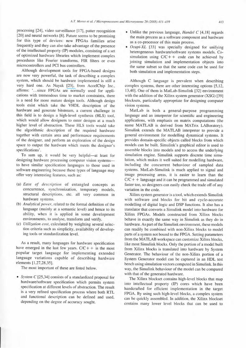
Fig. 3. Modular-blockset-based
assemble custom functions. These blocks provide controls to
access key aspects of the underlying FPGA resources' The
combination of high-level and low-level blocks supports a
wide range of implementation options to explore the
available irchitectures that can be implemented in an FPGA'
Consequently Matlab Simulink and Xilinx system
generator offer án ideal virtual prototyping environment in
*f,i"i, u system test can be run concurrently with hardware
and software models, using all the capabilities and toolboxes
iurnished Uy Matlab-Simulink in conjunction with powerful
hardware dlscription languages like VHDL' Moreover' they
offer designers a set of optimized hardware blocks that can be
combined to create much more complicated systems' thus
makingsystem
Blrü¡i Box
hardware binarization block'
for the kind of easilY described
needed for co-design.
modular reusable
3. Apptication examPles
3. 1. Binarization algorithm
When processing an image, thresholds constitute a very
important tool for detecting objects 13'9'3 1l' This technique
consist, of analysing eacñ pixel via image exploration in
order to determine whether its grey-level value is between
ihe specifiea threshold values (then a pre-established output'
f"m"wll%.- It#_ Il%k-:&l§yaam
GBn*r3tnr
Tr: ú/rrlsPaoel
E el ¡tion¡l
t o nr.ta nl
T r lr1Jo leP a ce 1
lqlodelSim_.:Palametets#
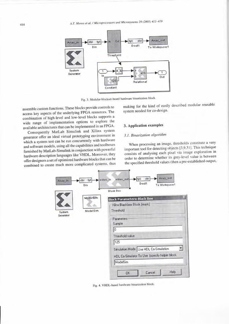
Fig. 4. VHDl-based hardware binarization block'
A.T. Moreo et al. / Microprocessors and Microsystems 29 (2005) 411-419 415
(a)this_block. setTopLevelLanguage('VHDL') ;th¡s_block.setEntityName('thres');
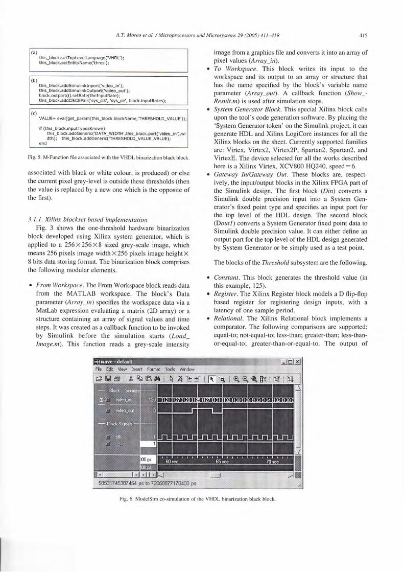
(b)this_block.addSimulinklnport('video_¡n') ;th¡s_block.addSimul¡n kOutport('v¡deo_out') ;bl ock. outpo rt( ¡). setRate (theI n putRate);this_block.addClkCEPair('sys_cl k','sys_ce', block. inputRates);
(c)VALUE= eval(get_param(this_block. blockName,'THRESHOLD_VALUE')) ;
if (this_block.inputTypesKnown )this_block.addGeneric('DATA_WIDTI'I',this*block. port('video_in'),width); this_block.addGener¡c('THRESHOLD_VALUE',VALUE);
end
Fig. 5. M-Function file associated with the VHDL binarization black block.
associated with black or white colour, is produced) or elsethe current pixel grey-level is outside these thresholds (thenthe value is replaced by a new one which is the opposite ofthe first).
3.1.1. Xilinx blockset based implementotionFig. 3 shows the one-threshold hardware binarization
block developed using Xilinx system generator, which isapplied to a 256X256 X 8 sized grey-scale image, whichmeans 256 pixels image widthX256 pixels image heightX8 bits data storing format. The binarization block comprisesthe following modular elements.
¡ From Workspace. The From Workspace block reads datafrom the MATLAB workspace. The block's Dataparameter (Array_in) specifies the workspace data via aMatlab expression evaluating a matrix (2D array) or astructure containing an array of signal values and timesteps. It was created as a callback function to be invokedby Simulink before the simulation starts (Load_Image.m). This function reads a grey-scale intensity
image from a graphics file and converts it into an array ofpixel values (Array _in).To Workspac¿. This block writes its input to theworkspace and its output to an array or structure thathas the name specified by the block's variable nameparameter (Aruay_out). A callback function (Show_-
Result.m) is used after simulation stops.
System Generator Block. This special Xilinx block callsupon the tool's code generation software. By placing the'System Generator token' on the Simulink project, it cangenerate FIDL and Xilinx LogiCore instances for all theXilinx blocks on the sheet. Currently supported familiesare: Virtex, Virtex2, Virtex2P, Sparlan2, Spartan2, and
VinexE. The device selected for all the works describedhere is a Xilinx Virtex, XCV800 HQ240, speed-6.Gateway In/Gateway Out. These blocks are, respect-ively, the input/output blocks in the Xilinx FPGA part ofthe Simulink design. The first block (Dln) converts a
Simulink double precision input into a System Gen-erator's fixed point type and specifies an input port forthe top level of the HDL design. The second block(Doutl) converts a System Generator fixed point data toSimulink double precision value. It can either define an
output port for the top level of the HDL design generatedby System Generator or be simply used as a test point.
The blocks of the Threshold subsystem are the following.
Constant. This block generates the threshold value (inthis example, 125).
Register. The Xilinx Register block models a D flip-flopbased register for registering design inputs, with a
latency of one sample period.Relational. The Xilinx Relational block implements a
comparator. The following comparisons are supported:equal-to; not-equal-to; less-than; greater-than; less-than-
or-equal-to; greater-than-or-equal-to. The output of
Fig. 6. ModelSim co-simulation of the VHDL binarization black block
A.T. Moreo et al. / Microprocessors and Microsystems 29 (2005) 411419
i##w
{a .-.,,r,rLi:,:::,,::
b
rd,Jifiñiiiifix3
:.,:§i.. ll
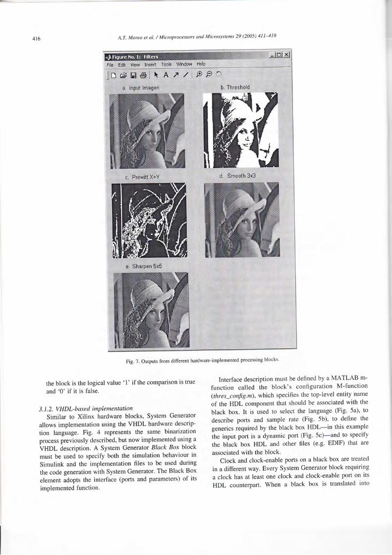
Fig. 7. Outputs from different hardware-implemented processing blocks
lillt-*
the block is the logical value 'f if the comparison is true
and '0' if it is false.
3. 1.2, V H DL-bas ed imPleme ntation
Similar to Xilinx hardware blocks, System Generator
allows implementation using the VHDL hardware descrip-
tion language. Fig. 4 represents the same binarization
process previously described, but now implemented using a
VHDL description. A System Generator Black Box block
must be used to specify both the simulation behaviour in
Simulink and the implementation files to be used during
the code generation with System Generator. The Black Box
element adopts the interface (ports and parameters) of its
implemented function.
Interface description must be defined by a MATLAB m-
function called the block's configuration M-function(thres-config.m), which specifies the top-level entity name
of the HDL component that should be associated with the
black box. It is used to select the language (Fig" 5a), to
describe ports and sample rate (Fig. 5b), to def,ne the
generics required by the black box HDL-in this example
the input port is a dynamic port (Fig. Sc)-and to specify
the black box HDL and other files (e'g' EDIF) that are
associated with the block.
Clock and clock-enable ports on a black box are treated
in a different way. Every System Generator block requiring
a clock has at least one clock and clock-enable port on its
HDL counterpart. When a black box is translated into
r'l',i;i::.::::; li§:b
A.T. Moreo et al. I Microprocessors and Microsystems 29 (2005) 411419
LineBr¡t'leÉ
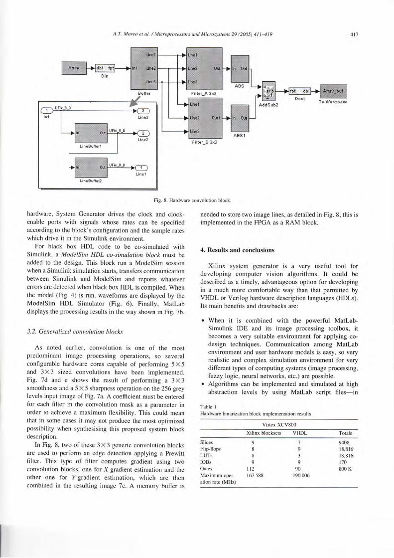
Fig. 8. Hardware convolution block.
hardware, System Generator drives the clock and clock-enable ports with signals whose rates can be specifiedaccording to the block's configuration and the sample rateswhich drive it in the Simulink environment.
For black box HDL code to be co-simulated withSimulink, a ModelSim HDL co-simulation block must beadded to the design. This block run a ModelSim sessionwhen a Simulink simulation starts, transfers communicationbetween Simulink and ModelSim and reports whatevereffors are detected when black box HDL is compiled. Whenthe model (Fig. a) is run, waveforrns are displayed by theModelSim HDL Simulator (Fig. 6). Finally, Marlabdisplays the processing results in the way shown in Fig. 7b.
3.2. Generalized convolution blocks
As noted earlier, convolution is one of the mostpredominant image processing operations, so severalconfigurable hardware cores capable of performing 5 X 5and 3 X 3 sized convolutions have been implemented.Fig. 7d and e shows the result of performing a 3 X 3smoothness and a 5 X 5 sharpness operation on the 256 greylevels input image of Fig .7a. A coefficient must be enteredfor each fllter in the convolution mask as a parameter inorder to achieve a maximum flexibility. This could meanthat in some cases it may not produce the most optimizedpossibility when synthesising this proposed system blockdescription.
In Fig. 8, two of these 3X3 generic convolution blocksare used to perlorm an edge detection applying a Prewittfilter. This type of filter computes gradient using twoconvolution blocks, one for X-gradient estimation and theother one for Y-gradient estimation, which are thencombined in the resulting image 7c. A memory buffer is
needed to store two image lines, as detailed in Fig. 8; this isimplemented in the FPGA as a RAM block.
4. Results and conclusions
Xilinx system generator is a very useful tool fordeveloping computer vision algorithms. It could bedescribed as a timely, advantageous option for developingin a much more comfortable way than that permitted byVHDL or Verilog hardware description languages (HDLs).Its main benefits and drawbacks are:
¡ When it is combined with the powerful Matl-ab-Simulink IDE and its image processing toolbox, itbecomes a very suitable environment for applying co-design techniques. Communication among Matlabenvironment and user hardwa¡e models is easy, so veryrealistic and complex simulation environment for verydifferent types of computing systems (image processing,fuzzy logic, neural networks, etc.) are possible.
o Algorithms can be implemented and simulated at highabstraction levels by using Matlab script files-in
Table I
Hardware binarization block implementation results
Virtex XCV800
Xilinx blocksets VHDL
Slices 9
Flip-flops 8
LUTs 8
IOBs 9
Gates 112Maximum oper- 167.588
ation rate (MHz)
7
9
3
9
90190.006
9408
18,816
1 8,8 l6170800 K
Filter_A 3>á
To Wod{sp¿6e
Filter B 3)á
418 A.T. Moreo et ú1. / Microprocessors and Microsystems 29 (2005) 411419
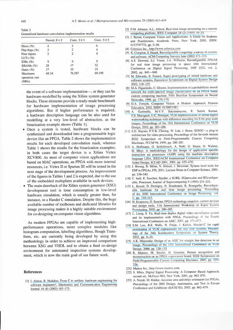
Table 2
Generalized hardware convolution implementation results
Prewitt X* Y Conv.3X3 Conv- 5 X 5
Slices (7o)
Flip-flops (7o)
Four inputsLtJTs (Vo)
IOBs (9o)
BRAMs (7o)
Gates (7o)
Maximumoperation rate(MHz)
4
3
2
9
28
17
68.34
3
2
2
9
t710'16.587
6
4
4
9
3219
69.195
the event of a software implementation-, or they can be
hardware-modelled by using the Xilinx system generator
blocks. These eiements provide a ready-made benchmarkfor hardware implementation of image processing
algorithms. But if higher performance is required,
a hardware description language can be also used formodelling at a very low-level of abstraction, as the
binarization example shows (Table 1).. Once a system is tested, hardware blocks can be
synthesized and downloaded into a programmable logicdevice like an FPGA. Table 2 shows the implementationresults for each developed convolution mask, whereas
Table 1 shows the results for the binarization examples;
in both cases the target device is a Xilinx VirtexXCV800. As most of computer vision applications are
based on MAC operations, an FPGA with more internal
resources, i.e. Virtex II or Spartan III will be tested in the
next stage of the development process. An improvement
of the figures in Tables 1 and2 is expected, due to the use
of the embedded multipliers available in such devices.o The main drawback of the Xilinx system generator (XSG)
development tool is time consurnption in low-ievelhardware simulation, which is usually greater than, forinstance, in a Handel C simulation. Despite this, the huge
available number of toolboxes and dedicated libraries forimage processing makes it a highly suitable environment
for co-designing on computer vision algorithms.
As modern FPGAs are capable of implementing high-performance operations, rnore complex modules likehistogram computation, labelling algorithms, Hough Trans-
form, etc. are culrently being deveioped by using this
methodology in order to achieve an improved comparison
between XSG and VHDL and to obtain a final co-design
environment for automated inspection systems develop-ment, which is now the main goal of our future work.
References
[1] I. Alston, B. Madahar, From C to netlists: hardware engineering for
software engineers?, Electronics and Communication Engineering
Journal 14 (4) (2002) 165-173.
l2l P.M. Athanas, A.L. Abbott, Real-time image processing on a custom
computing platform, IEEE Conrputer 28 (2) (1995) 16-25.
[3] J. Bemrl, Computer Vision and Applications: A Guide for Students
and Practitioners, Academic Press, New York, 2000, ISBN:
0123'1 9'7 7 7 2, pp. 5-30.Celoxica Inc., http://www.celoxica'comK. Compton, S. Hauck, R.econfigurable computing: a survey of systems
and software, ACM Computing Surveys June {2002) 17 l-210.
t6l A.S. Dawood, S.J" Visser, J.A Williams, Reconfigurable FPGAS
for real time image processing in space l4th Intemational
Conference on Digital Signal Processing, DSP 2002, vol' 2'
2002, pp. 845-848.[7] M. Edwards, B. Fozard, Rapid prototyping of mixed hardware and
software systems, Euromicro Symposium on Digital System Design
2002; 118-125.
t8l M.A. Figueiredo, C. Gloster, Implementation of a probabilistic neural
network for multi-spectral image classification on an FPGA based
custom computing machine, Fifth Brazilian Symposium on Neural
Networks, 1998, pp. 1"14-179.
tgl D.A. Forsyth, Computer Vision: A Modern Approach, Pearson
Education, 2002, ISBN: 0 1 3085 I 98 I .
t10l A. Garimella, M.V.V. Satyanarayana, R. Satish Kumar,
P.S. Murugesh, U.C. Niranjan, VLSI implementation of online digital
watermarking technique with difference encoding for 8-bit gray scale
images, Proceedings of the l6th Intemational Conference on VLSI
Design, 2003, pp. 283-288.
tlll S.D. Haynes, P.Y.K. Cheung, W. Luk, J. Stone, SONIC-a plug-in
architecture for video processing, Proceedings of the Seventh Annual
IEEE Symposium on Field-Programmable Custom Computing
Machines, FCCM'99, 1999, pp. 280-281.
[l2] A. Hoffrnann, O. Schliebusch, A. Nohl, G. Braun, O. Wahlen'
H. Meyr, A methodology for the design of application specific
instruction set processors (ASIP) using the machine description
language LISA, IEEE/ACM international Conference on Computer
Aided Design, ICCAD 2001, 2001, pp. 625-630.
[3] J. Hwang, B. Milne, N. Shirazi, J' Stroomer, System level tools for
DSP in FPGAs, FPL 200 I , Lecture Notes in Computer Science, 200 I 'pp.534-543.
tl4l C. Iseli, E. Sanchez, Spyder, a SURE, SUperscalar and REconfigur-
able, Processor, Joumal of Supercomputing 9 (1995) 231-252'
[15] L. Kessal, D. Demigny, N. Boudouani, R. Bourguiba, Reconfigur-
able hardware for real time image processing, Proceeding
of the 2000 Intemational Conference on Image Processing' vol'
3, pp. 110-113.
[6] H. Krupnova, G. Saucier, FPGA technology snapshot: current devices
and design tools, llth Intemational Workshop on Rapid System
Prototyping, 2000, pp. 200-205.
[17] L. Liang, S. Yu, Real-time duplex digita'l video surleillance srstem
and its implementation with FPGA, Proceedings of the Fourth
Intemational Conference on ASIC, 2001, pp. 471-{73'
tl8l S.M. Loo, B.E. Wells, N. Freije. J. Kulick. Handel-C for rapid
prototyping of VLSI coprocessors for real time systems, Proceed-
ings of the 34th Southeastern Symposium on System Theory,
2002, pp. 6-10.
t19l A.K. Majumdar, Design of an ASIC for straight line detection in an
image, Proceedings of the l3th International Conference on VLSI
Design, 2000, pp. 128-133.
[20] R. Manner, M. Sessler, H. Simmler, Pattern recognition and
reconstruction on an FPGA coprocessor board, IEEE Symposiun.r on
Field-Programmable Custom Computing Machines, 2003, pp' 325-
326.
[2ll Matrox Inc., http://www.matrox com
[22] S. Mitra, Digitai Signal Processing: A Computer Baseti Approach,
second ed., McGraw-Hill, New York, 2001, pp. 862-870'
[23] A. Nayak, M. Haldar, Accurate area and delay estimators for FPGAs'
Proceedings of the 2002 Design, Automation, and Test in Europe
Conference and Exhibition (DATE'O2), 2002, pp.862-870'
f41
t5l
A.T. Moreo et al. / Microprocessors and Micrr¡»,stetns 29 (2005) 411419 419
[24] L. O'Donnell, G.L. Williams, A.J. Lacey, N.L. Seed, P.R. Thome,A.C. Zawada, P.A. Ivey, A 3-D re-configurable image processing
element, IEE Colloquium on High Performance Architectures forReal-Time Image Processing (Ref. no. l998ll9'7),1998, pp. l-7.
t25l P.R. Panda, SystemC-a modeling platfomr supporting multipledesign abstractions, Proceedings of the 14th International Symposiumon System Synthesis,200l, pp. 75-80.
[26] M.E. Rizkalla, K. Palaniswamy, A.S.C. Sinha, M. El-sharkawy,P. Salama, S. Lyshevski, H. Gundrum, ASIC memory design of 2-Dmedian filters, Proceedings of the 43rd IEEE Midwest Symposium on
Circuits and Systems. vol. l, 2000, pp. 354-357.
[27] L. Semeria, A. Ghosh, Methodology for hardware/software co-verification in C/C* *, Proceedings of the ASP-DAC 2000 DesignAutomation Conference, 2002, pp. 123-128.
[28] L. Semeria, A. Seawright, R. Mehra, D. Ng, A. Ekanayake,B. Pangrle, RTL C-based methodology for designing and verifyinga multi+hreaded processor, Design Automation Conference, 2002,pp. 123-128.
[29] L. Shijian, G.Li,Z. Junzhu, L. Feng, A CPLD design of real timesystem for point targets detection in infrared image sequences,Proceeding of the Fifth International Conference on ASIC, 2l-24October vol. 2, 2003, pp. 906-909.
[30] G. Spivey, S.S. Bhattacharyya, K. Nakajima, Logic foundry:rapid prototyping of FPGA-based DSP systems, Proceedings ofthe ASP-DAC 2003 Design Automation Conference, 2003, pp.
374-38 I .
[31] G. Stockman, Computer Vision, Pearson Education, 2001., ISBN:0130307963, pp. 374-381.
[32] The MathWorks Inc., http://www.mathworks.com
[33] The Ocapi XL initiative, http://www.imec.be/design/ocapi
[34] The SystemC Initiative, htrp://www.systemc.org
[35] T. Todman, W. Luk, Real¡ime extensions to a C-like hardwaredescription language, llth Annual IEEE Symposium on Field-Programmable Custom Computing Machines, FCCM 2003, 9-11April, 2003, pp. 302-304.
t36l I.S. Uzun, A.A.A. Bouridane, FPGA implemenrarions of fasr Fouriertransforms for real-time signal and image processing, IEEEInternational Conference on Field-Programmable Technology(FPr), 2003, pp. 102-109.
[37] K. Wiatr, E. Jamro, Implementation image data convolutions operationsin FPGA reconflgurable structures for real-time vision systems,Intemational Conference on Information Technology: Coding andComputing, 2000, pp. 152-157.
[38] J. Woodfill, B. Von Herzen, Real-time srereo vision on rhe PARTSreconfigurable computer, Proceedings of the Fifth Annual IEEESymposium on FPGAs for Custom Computing Machines, 1991, pp.20t-210.
[39] Xilinx Inc., hup://www,xilinx.com
[40] X. Zhang, K.W. Ng, A review of high-level synthesis for dynamicallyreconfigurable FPGAs, Microprocessors and Microsystems 24 (4)(2000) 199-21 L
[41] T. Yokota, M. Nagafuchi, Y. Mekada, T. Yoshinaga, K. Ootsu,T. Baba, A scalable FPGA-based custom computing machine for a
medical image processing, Proceedings of the l0th Annual IEEESymposium on Fie'ld-Programmable Custom Computing Machines,2002, pp.307-308.
Ana Toledo Moreo, BE, MSc, is a PhDstudent and Assistant Lecturer in the
Electronics Technology Department ofthe Technical University of Cartagena,
Spain. Her research has been mainlyfocussed in developing lowJevel image-processing algorithms for FPGAs. She isalso interested in artificial neural networks.principally in the improvement of leaming
algorithms. She has a number of publi-cations relaled with the two areas in
intemational joumals and conferences. Currently, she is a VisitorResearcher in the University of Reading, UK.
Pedro J. Navarro Lorente. received the
MSc degree in Electrical and Electronicsin 2000 from Technical University ofCartagena, Murcia, Spain; actually he is
taking PhD degree in Mechatronics and
Engineering in Technical University ofCartagena, Murcia, Spain. Since 2000 he
has participated in different projectsfocused on computer vision and robotics
application for the industry. In 2001, he
joined the Systems and Electronic Engin-eering Division (DSIE). He is currently working as associated professorat the Technical University of Cartagena, Murcia, Spain, in the fleld ofelectronics. His current research interests include hardware-based
computer vision algorithms, mechatronics and robotics, and he is
author of various papers on these topics.
Fulgencio Soto Valles, BE, MSc, is a PhD
student and Assistant Lecturer on the
Electronics Technology Department ofthe Technical University of Cartagena,
Spain. His research has been mainlyfocussed in developing digital controlsfor power electronic systems. Also, he is
interested in artificial vision, principally in
the improvement of quality inspection
sysfems. He has a number of publications
related with the two areas in intemationaljoumals and conferences. Currently, he is a Visitor Researcher in the
University of Reading, UK.