Exergetic analysis of a double stage LiBr–H2O thermal compressor cooled by air/water and driven by...
14
Exergetic analysis of a double stage LiBr–H 2 O thermal compressor cooled by air/water and driven by low grade heat M. Izquierdo a, * ,1 , M. Venegas b,1 , N. Garcı ´a b,1 , E. Palacios c a Instituto C.C. Eduardo Torroja (CSIC), Edificacion y Habitabilidad, C. Serrano Galvache, 4, 28033 Madrid, Spain b Departamento de Ingenierı ´a Te ´rmica y de Fluidos, Universidad Carlos III de Madrid, Avda. Universidad, 30, 28911 Legane ´s, Madrid, Spain c Departamento de Meca ´ nica Industrial, EUITI, Universidad Polite ´ cnica de Madrid, Ronda de Valencia, 3, 28012 Madrid, Spain Received 22 March 2004; accepted 30 June 2004 Available online 1 September 2004 Abstract In the present paper, an exergetic analysis of a double stage thermal compressor using the lithium bro- mide–water solution is performed. The double stage system considered allows obtaining evaporation tem- peratures equal to 5 °C using solar heat coming from flat plate collectors and other low grade thermal sources. In this study, ambient air and water are alternatively used as cooling fluids without crystallization problems up to condensation–absorption temperatures equal to 50 °C. The results obtained give the entropy generated, the exergy destroyed and the exergetic efficiency of the double stage thermal compressor as a function of the absorption temperature. The conclusions obtained show that the irreversibilities gen- erated by the double stage thermal compressor will tend to increase with the absorption temperature up to 45 °C. The maximum value corresponds to 1.35 kJ kg 1 K 1 . The entropy generated and the exergy destroyed by the air cooled system are higher than those by the water cooled one. The difference between the values increases when the absorption temperature increases. For an absorption temperature equal to 50 °C, the air cooled mode generates 14% more entropy and destroys 14% more exergy than the water cooled one. Also, the results are compared with those of previous studies for single and double effect air cooled and 0196-8904/$ - see front matter Ó 2004 Elsevier Ltd. All rights reserved. doi:10.1016/j.enconman.2004.06.016 * Corresponding author. Tel./fax: +34 91 871 3248. E-mail address: [email protected] (M. Izquierdo). 1 Unidad Asociada de Ingenierı ´a Te ´rmica y de Fluidos CSIC-UC3M. www.elsevier.com/locate/enconman Energy Conversion and Management 46 (2005) 1029–1042
Transcript of Exergetic analysis of a double stage LiBr–H2O thermal compressor cooled by air/water and driven by...

www.elsevier.com/locate/enconman
Energy Conversion and Management 46 (2005) 1029–1042
Exergetic analysis of a double stage LiBr–H2O thermalcompressor cooled by air/water and driven by low grade heat
M. Izquierdo a,*,1, M. Venegas b,1, N. Garcıa b,1, E. Palacios c
a Instituto C.C. Eduardo Torroja (CSIC), Edificacion y Habitabilidad, C. Serrano Galvache, 4, 28033 Madrid, Spainb Departamento de Ingenierıa Termica y de Fluidos, Universidad Carlos III de Madrid, Avda. Universidad, 30,
28911 Leganes, Madrid, Spainc Departamento de Mecanica Industrial, EUITI, Universidad Politecnica de Madrid, Ronda de Valencia, 3, 28012 Madrid,
Spain
Received 22 March 2004; accepted 30 June 2004
Available online 1 September 2004
Abstract
In the present paper, an exergetic analysis of a double stage thermal compressor using the lithium bro-
mide–water solution is performed. The double stage system considered allows obtaining evaporation tem-
peratures equal to 5 �C using solar heat coming from flat plate collectors and other low grade thermal
sources. In this study, ambient air and water are alternatively used as cooling fluids without crystallizationproblems up to condensation–absorption temperatures equal to 50 �C. The results obtained give the
entropy generated, the exergy destroyed and the exergetic efficiency of the double stage thermal compressor
as a function of the absorption temperature. The conclusions obtained show that the irreversibilities gen-
erated by the double stage thermal compressor will tend to increase with the absorption temperature up to
45 �C. The maximum value corresponds to 1.35 kJ kg�1 K�1. The entropy generated and the exergy
destroyed by the air cooled system are higher than those by the water cooled one. The difference between
the values increases when the absorption temperature increases. For an absorption temperature equal to 50
�C, the air cooled mode generates 14% more entropy and destroys 14% more exergy than the water cooledone. Also, the results are compared with those of previous studies for single and double effect air cooled and
0196-8904/$ - see front matter � 2004 Elsevier Ltd. All rights reserved.
doi:10.1016/j.enconman.2004.06.016
* Corresponding author. Tel./fax: +34 91 871 3248.
E-mail address: [email protected] (M. Izquierdo).1 Unidad Asociada de Ingenierıa Termica y de Fluidos CSIC-UC3M.
1030 M. Izquierdo et al. / Energy Conversion and Management 46 (2005) 1029–1042
water cooled thermal compressors. The conclusions show that the double stage system has about 22% less
exergetic efficiency than the single effect one and 32% less exergetic efficiency than the double effect one.
� 2004 Elsevier Ltd. All rights reserved.
Keywords: Double stage thermal compressor; Low-grade heat; Entropy generated; Exergy destroyed; Exergetic
efficiency
1. Introduction
Cooling through absorption cycles has been traditionally considered one of the most desirableapplications for residual and renewable energy sources. In the same way, the ability to use lowgrade heat, such as that obtained from fuel cells and residual heat from engines, is a strong reasonfor using absorption machines. Some fuel cells employ the mechanism where hydrogen is sepa-rated from methane, and then the hydrogen is ionized and reacts with oxygen, producing an elec-tric current and water vapor. This water vapor, at a temperature of about 60–85 �C, can be usedto feed a single effect absorption cooling cycle. Other facts, as independence from electric grids,reduction of CO2 emissions and use of natural refrigerants, contribute to increase the attractive-ness of absorption refrigeration systems.
The interest in absorption refrigeration systems operated with low temperature heat has in-creased considerably in the last years [1–4]. Lamp and Ziegler [5] reviewed the European effortsin this direction for solar air conditioning applications and highlighted the most outstanding ideasand experiences. They emphasize in their conclusions that remarkable advances are needed inabsorption technology.
Alternatives for using low temperature heat sources imply necessarily the use of absorption sys-tems able to work with low grade heat, i.e. with temperatures lower than 90 �C. To take advantageof this heat at high condensation temperatures, advanced multistage absorption cycles should beadopted. These cycles have lower COPs than standard ones but allow operation with generationand condensation temperatures within the indicated limits [6].
Some experimental and theoretical works related to the use of low temperature heat using dou-ble stage absorption systems include the works developed by Arzoz et al. [7], Venegas et al. [8],Medrano et al. [9], Schweigler et al. [10], Lamp et al. [11] and Ziegler and Riesch [12]. Recently,Sumathy et al. [2] reported the successful operation of a double stage absorption cycle for solar airconditioning employing LiBr–H2O as the working pair, feeding the generators with hot water attemperatures ranging from 60 to 75 �C. Also, in a recent paper of Kim and Machielsen [13], theauthors conclude that single stage systems can yield higher average cooling efficiency than doublestage systems only with a vacuum tube collector or its comparable types. Further, they recom-mend a low cost double stage chiller for use with flat plate collectors.
The final absorption temperature of air cooled systems is higher than that of similar watercooled ones. As result, the temperature of the heat source driving the absorption machine is high-er, decreasing the contribution of the low temperature heat source. An entropic balance takinginto account the entropy generation between internal fluids and between these and the externalfluids is also useful. However, there is little bibliography on the irreversibilities generated, whichcan only be evaluated on the basis of the second law. Some works analyzing this problem include
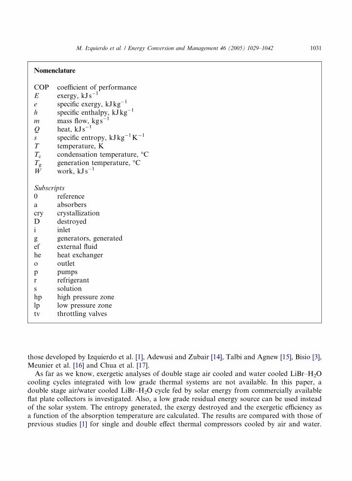
Nomenclature
COP coefficient of performanceE exergy, kJs�1
e specific exergy, kJkg�1
h specific enthalpy, kJkg�1
m mass flow, kgs�1
Q heat, kJs�1
s specific entropy, kJkg�1 K�1
T temperature, KTc condensation temperature, �CTg generation temperature, �CW work, kJs�1
Subscripts
0 referencea absorberscry crystallizationD destroyedi inletg generators, generatedef external fluidhe heat exchangero outletp pumpsr refrigerants solutionhp high pressure zonelp low pressure zonetv throttling valves
M. Izquierdo et al. / Energy Conversion and Management 46 (2005) 1029–1042 1031
those developed by Izquierdo et al. [1], Adewusi and Zubair [14], Talbi and Agnew [15], Bisio [3],Meunier et al. [16] and Chua et al. [17].
As far as we know, exergetic analyses of double stage air cooled and water cooled LiBr–H2Ocooling cycles integrated with low grade thermal systems are not available. In this paper, adouble stage air/water cooled LiBr–H2O cycle fed by solar energy from commercially availableflat plate collectors is investigated. Also, a low grade residual energy source can be used insteadof the solar system. The entropy generated, the exergy destroyed and the exergetic efficiency asa function of the absorption temperature are calculated. The results are compared with those ofprevious studies [1] for single and double effect thermal compressors cooled by air and water.
1032 M. Izquierdo et al. / Energy Conversion and Management 46 (2005) 1029–1042
2. Low grade thermal system coupled to the absorption cooling system
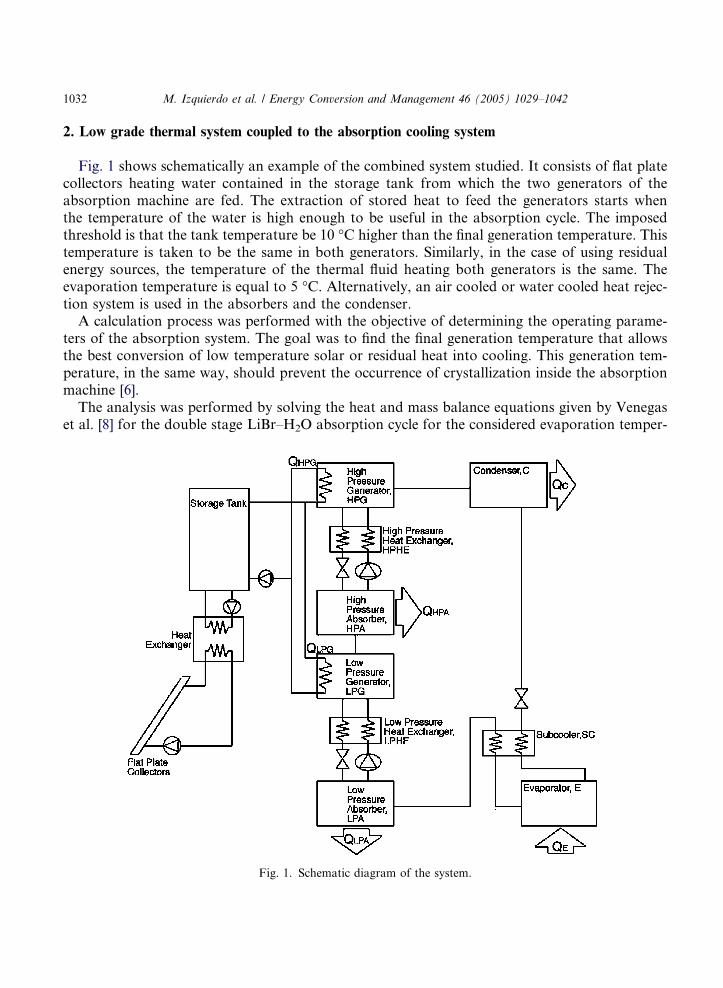
Fig. 1 shows schematically an example of the combined system studied. It consists of flat platecollectors heating water contained in the storage tank from which the two generators of theabsorption machine are fed. The extraction of stored heat to feed the generators starts whenthe temperature of the water is high enough to be useful in the absorption cycle. The imposedthreshold is that the tank temperature be 10 �C higher than the final generation temperature. Thistemperature is taken to be the same in both generators. Similarly, in the case of using residualenergy sources, the temperature of the thermal fluid heating both generators is the same. Theevaporation temperature is equal to 5 �C. Alternatively, an air cooled or water cooled heat rejec-tion system is used in the absorbers and the condenser.
A calculation process was performed with the objective of determining the operating parame-ters of the absorption system. The goal was to find the final generation temperature that allowsthe best conversion of low temperature solar or residual heat into cooling. This generation tem-perature, in the same way, should prevent the occurrence of crystallization inside the absorptionmachine [6].
The analysis was performed by solving the heat and mass balance equations given by Venegaset al. [8] for the double stage LiBr–H2O absorption cycle for the considered evaporation temper-
Fig. 1. Schematic diagram of the system.
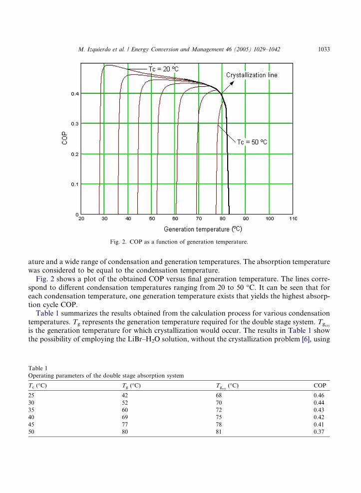
Fig. 2. COP as a function of generation temperature.
M. Izquierdo et al. / Energy Conversion and Management 46 (2005) 1029–1042 1033
ature and a wide range of condensation and generation temperatures. The absorption temperaturewas considered to be equal to the condensation temperature.
Fig. 2 shows a plot of the obtained COP versus final generation temperature. The lines corre-spond to different condensation temperatures ranging from 20 to 50 �C. It can be seen that foreach condensation temperature, one generation temperature exists that yields the highest absorp-tion cycle COP.
Table 1 summarizes the results obtained from the calculation process for various condensationtemperatures. Tg represents the generation temperature required for the double stage system. Tgcry
is the generation temperature for which crystallization would occur. The results in Table 1 showthe possibility of employing the LiBr–H2O solution, without the crystallization problem [6], using
Table 1
Operating parameters of the double stage absorption system
Tc (�C) Tg (�C) Tgcry(�C) COP
25 42 68 0.46
30 52 70 0.44
35 60 72 0.43
40 69 75 0.42
45 77 78 0.41
50 80 81 0.37
1034 M. Izquierdo et al. / Energy Conversion and Management 46 (2005) 1029–1042
low temperature solar heat coming from flat plate collectors, or residual heat, and condensation-absorption temperatures as high as 50 �C.
The double stage system analyzed is considered in the following. The irreversibilities generatedusing low grade thermal sources and air/water cooled modes are determined. The entropy gener-ation and exergy destruction models used and the results obtained are described in the following.
3. Entropy generated and exergy destroyed by the double stage thermal compressor
The physical exergetic balance applied to a fixed control volume is given by the following equa-tion, according to Bejan et al. [18]:
0 ¼X
1 � T 0
T j
� �Qj � W cv þ
Xmiei �
Xmoeo � ED ð1Þ
where Q is the heat transfer rate from or to the system, Wcv the mechanical power supplied by orto the system, ED the exergy destroyed because of the internal irreversibilities and e the physicalcomponent of the exergy transfer associated with the streams of matter. When the kinetic and po-tential energies are neglected, according to Bejan et al. [18], the physical exergy �e� can be evaluatedas
e ¼ ðh� h0Þ � T 0ðs� s0Þ ð2Þ
The specific physical exergy of a flow of matter destroyed (eD) as a consequence of the specificentropy generated (sg) can also be evaluated applying the Gouy–Stodola theorem as
eD ¼ T 0 � sg ð3Þ
where T0 is the reference temperature. In the present work T0 = 298 K, which is the comfort tem-perature. In the analysis that follows, heat losses to ambient air will not be taken into account.The double stage thermal compressor is represented in Fig. 3. It consists of two absorbers, twogenerators, two heat exchangers, the solution pumps and the throttling valves. The compressor,driven by the heat produced by the field of solar collectors or the residual heat, absorbs thelow pressure refrigerant vapor (point 8) coming from the evaporator and by means of a compres-sion produces refrigerant as superheated vapor at high pressure and high temperature (point 5).
To perform this transformation, the solution flow must be provided with work. This work is theexergy of the external fluid heat that feeds the generators, and the exergy transferred to the solu-tion by means of the pumps, driven by electricity. The heat necessary to drive this compressor canbe generated by a field of flat plate thermal solar collectors. Also, residual heat obtained from fuelcells and engines can be used.
3.1. Generators
The external thermal fluid, pressurized hot water heated by flat plate solar collectors or comingfrom residual sources, drives the compressor via the generators. The physical and thermodynamicproperties of the external thermal fluid have been evaluated taking into account that a tempera-ture difference of 10 �C between the concentrated solution coming out from the generators and the
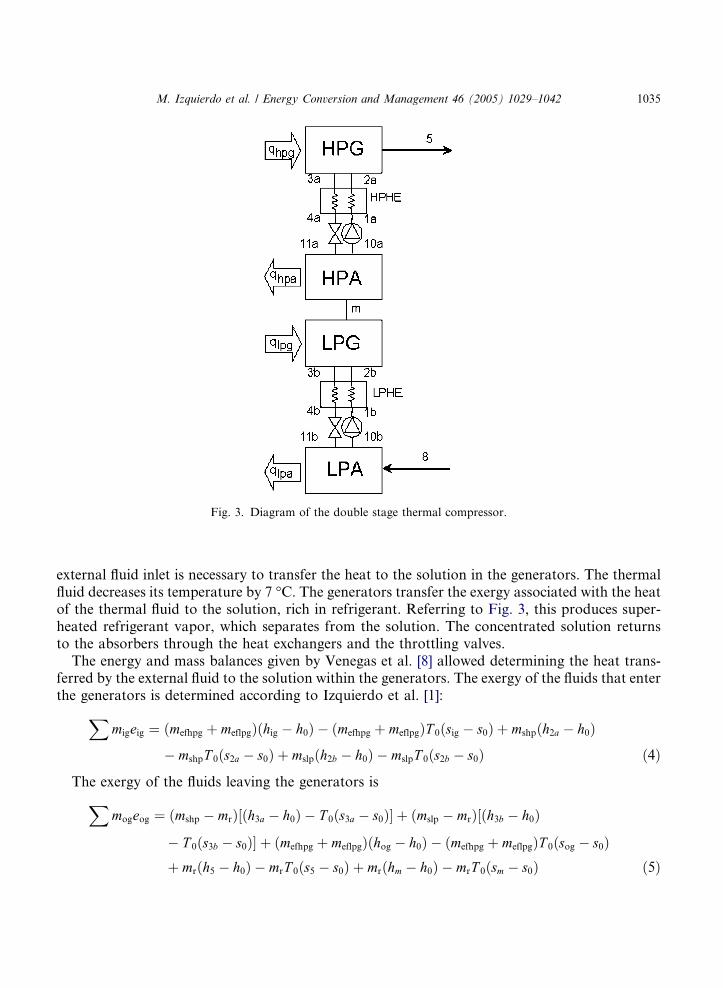
Fig. 3. Diagram of the double stage thermal compressor.
M. Izquierdo et al. / Energy Conversion and Management 46 (2005) 1029–1042 1035
external fluid inlet is necessary to transfer the heat to the solution in the generators. The thermalfluid decreases its temperature by 7 �C. The generators transfer the exergy associated with the heatof the thermal fluid to the solution, rich in refrigerant. Referring to Fig. 3, this produces super-heated refrigerant vapor, which separates from the solution. The concentrated solution returnsto the absorbers through the heat exchangers and the throttling valves.
The energy and mass balances given by Venegas et al. [8] allowed determining the heat trans-ferred by the external fluid to the solution within the generators. The exergy of the fluids that enterthe generators is determined according to Izquierdo et al. [1]:
Xmigeig ¼ ðmefhpg þ meflpgÞðhig � h0Þ � ðmefhpg þ meflpgÞT 0ðsig � s0Þ þ mshpðh2a � h0Þ
� mshpT 0ðs2a � s0Þ þ mslpðh2b � h0Þ � mslpT 0ðs2b � s0Þ ð4Þ
The exergy of the fluids leaving the generators is
Xmogeog ¼ ðmshp � mrÞ½ðh3a � h0Þ � T 0ðs3a � s0Þ� þ ðmslp � mrÞ½ðh3b � h0Þ
� T 0ðs3b � s0Þ� þ ðmefhpg þ meflpgÞðhog � h0Þ � ðmefhpg þ meflpgÞT 0ðsog � s0Þþ mrðh5 � h0Þ � mrT 0ðs5 � s0Þ þ mrðhm � h0Þ � mrT 0ðsm � s0Þ ð5Þ
1036 M. Izquierdo et al. / Energy Conversion and Management 46 (2005) 1029–1042
The exergy destroyed because of the irreversibilities in the heat transfer between the externalfluid and the solution is obtained by applying Eq. (1) and taking into account the energy and massbalances.
EDg ¼ T 0½mrðs5 � s3aÞ þ mrðsm � s3bÞ þ mshpðs3a � s2aÞ þ mslpðs3b � s2bÞ�þ ðmefhpg þ meflpgÞT 0ðsog � sigÞ ð6Þ
The first term is positive, while the second one is negative. The global balance is positive. Thegenerated entropy will be
Sgg ¼ ½mrðs5 � s3aÞ þ mmðsm � s3bÞ þ mshpðs3a � s2aÞ þ mslpðs3b � s2bÞ�þ ðmefhpg þ meflpgÞðsog � sigÞ ð7Þ
3.2. Solution heat exchangers
In this case, the following equation is obtained for the exergy of the fluids that enter the solu-tion heat exchangers:
Xmiheeihe ¼ ðmshp � mrÞ½ðh3a � h0Þ � T 0ðs3a � s0Þ� þ ðmslp � mrÞ½ðh3b � h0Þ � T 0ðs3b � s0Þ�þ mshpðh1a � h0Þ þ mslpðh1b � h0Þ � mshpT 0ðs1a � s0Þ � mslpT 0ðs1b � s0Þ ð8Þ
The exergy of the fluids leaving the solution heat exchangers can be expressed as
Xmoheeohe ¼ ðmshp � mrÞ½ðh4a � h0Þ � T 0ðs4a � s0Þ� þ ðmslp � mrÞ½ðh4b � h0Þ � T 0ðs4b � s0Þ�þ mshpðh2a � h0Þ þ mslpðh2b � h0Þ � mshpT 0ðs2a � s0Þ � mslpT 0ðs2b � s0Þ ð9Þ
Finally, the exergy destroyed because of the irreversibilities in the heat transfer between theconcentrated and dilute solution flows is obtained by
EDhe ¼ ðmshp � mrÞT 0ðs4a � s3aÞ þ ðmslp � mrÞT 0ðs4b � s3bÞ þ mshpT 0ðs2a � s1aÞþ mslpT 0ðs2b � s1bÞ ð10Þ
The first two terms are negative, while the other two are positive. The balance of exergy destruc-tion is positive and the production of entropy is
Sghe ¼ ðmshp � mrÞðs4a � s3aÞ þ ðmslp � mrÞðs4b � s3bÞ þ mshpðs2a � s1aÞ þ mslpðs2b � s1bÞ ð11Þ
3.3. Solution pumps
The pumps transport the dilute solution (rich in refrigerant) in the liquid state from the suctionside (absorber) to the discharge side (generator), raising its pressure. The power of the pumps wp isobtained from
0 ¼ �wphp � mshph1a þ mshph10a ð12Þ
0 ¼ �wplp � mslph1b þ mslph10b ð13Þ
M. Izquierdo et al. / Energy Conversion and Management 46 (2005) 1029–1042 1037
The exergy of the solution at the intake (ip) and impulsion (op) of the solution pumps isobtained using the following equations:
Xmipeip ¼ mshpðh10a � h0Þ þ mslpðh10b � h0Þ � T 0mshpðs10a � s0Þ � T 0mslpðs10b � s0Þ
� whp � wlp ð14ÞX
mopeop ¼ mshpðh1a � h0Þ þ mslpðh1b � h0Þ � T 0mshpðs1a � s0Þ � T 0mslpðs1b � s0Þ ð15Þ
The destroyed exergy and the entropy generated are, respectively:
EDp ¼ mshpT 0ðs1a � s10aÞ þ mslpT 0ðs1b � s10bÞ > 0 ð16Þ
Sgp ¼ mshpðs1a � s10aÞ þ mslpðs1b � s10bÞ ð17Þ
3.4. Throttling valves
This component reduces the pressure of the concentrated solution from the high pressure zone(generators) towards the low pressure zone (absorbers). The following equations show the energybalances through the pressure reduction valves:
0 ¼ ðmshp � mrÞh4a � ðmshp � mrÞh11a ð18Þ
0 ¼ ðmslp � mrÞh4b � ðmslp � mrÞh11b ð19Þ
The exergies of the solution at the entrance and the exit of the pressure reduction valves aregiven by
Xmitveitv ¼ ðmshp � mrÞðh4a � h0Þ þ ðmslp � mrÞðh4b � h0Þ � T 0ðmshp � mrÞðs4a � s0Þ
� T 0ðmslp � mrÞðs4b � s0Þ ð20ÞX
motveotv ¼ ðmshp � mrÞðh11a � h0Þ þ ðmslp � mrÞðh11b � h0Þ � T 0ðmshp � mrÞðs11a � s0Þ
� T 0ðmslp � mrÞðs11b � s0Þ ð21Þ
The following equations show the exergy destroyed and the entropy generated in the throttlingvalves:
EDtv ¼ ðmshp � mrÞT 0ðs11a � s4aÞ þ ðmslp � mrÞT 0ðs11b � s4bÞ ð22Þ
Sgtv ¼ ðmshp � mrÞðs11a � s4aÞ þ ðmslp � mrÞðs11b � s4bÞ ð23Þ
The exergy destroyed, EDtv, is higher than zero, since the differences (s11 � s4) are positive in thelow and high pressures zones. The expansion of the solution in the throttling valves always occurswith an increase of entropy.
1038 M. Izquierdo et al. / Energy Conversion and Management 46 (2005) 1029–1042
3.5. Absorbers
Absorbers are the components of the thermal compressor that absorb the refrigerant vapor,which condenses in the solution. Classical air cooled absorbers have to transfer the absorptionheat first from the solution to an intermediate fluid, generally water, and afterwards from thiswater to the air. Consequently, an intermediate heat exchanger between the solution and theair is necessary. The total temperature difference between the solution and the air is shared bythe solution–water heat exchanger and by the water–outside air heat exchanger. Since air is notan efficient heat exchanger fluid, greater surfaces of exchange are necessary to reduce the solutiontemperature close to the outdoor air temperature.
In this study, the temperature difference between the solution and the air/water has been re-duced to 10 �C, i.e. with an external dry bulb/cooling water temperature of 30 �C, a final absorp-tion temperature of 40 �C can be reached. A temperature increase in the absorber external fluidequal to 7 �C has been assumed.
The following equation shows the exergy of the mass flows entering the absorbers, i.e., refrig-erant vapor, dilute solution and external fluid.
Xmiaeia ¼ mrðh8 � h0Þ �mrT 0ðs8 � s0Þ þmrðhm � h0Þ �mrT 0ðsm � s0Þþ ðmshp �mrÞðh11a � h0Þ þ ðmslp �mrÞðh11b � h0Þ � T 0ðmshp �mrÞðs11a � s0Þ� T 0ðmslp �mrÞðs11b � s0Þ þ ðmefhpa þmeflpaÞðhia � h0Þ � ðmefhpa þmeflpaÞT 0ðsia � s0Þ
ð24Þ
The exergy of the mass flows in the exit of the absorbers, i.e. concentrated solution and externalfluid, is given by
Xmoaeoa ¼ mshpðh10a � h0Þ þ mslpðh10b � h0Þ � mshpT 0ðs10a � s0Þ � mslpT 0ðs10b � s0Þ
þ ðmefhpa þ meflpaÞðhoa � h0Þ � ðmefhpa þ meflpaÞT 0ðsoa � s0Þ ð25Þ
The exergy destroyed and the entropy generated in both absorbers can be expressed through thefollowing equations:
EDa ¼ mrT 0ðs11b � smÞ þ mrT 0ðs11a � s8Þ þ mshpT 0ðs10a � s11aÞ þ mslpT 0ðs10b � s11bÞþ ðmefhpa þ meflpaÞT 0ðsoa � siaÞ ð26Þ
Sga ¼ mrðs11b � smÞ þ mshpðs10a � s11aÞ þ mrðs11a � s8Þ þ mslpðs10b � s11bÞþ ðmefhpa þ meflpaÞðsoa � siaÞ ð27Þ
3.6. Total entropy generated and exergy destroyed
Summing up the above equations, the total exergy destroyed and the entropy generated by thedouble stage thermal compressor are obtained as
ED ¼ mrT 0ðs5 � s8Þ þ ðmefhpg þ meflpgÞT 0ðsog � sigÞ þ ðmefhpa þ meflpaÞT 0ðsoa � siaÞ ð28Þ
M. Izquierdo et al. / Energy Conversion and Management 46 (2005) 1029–1042 1039
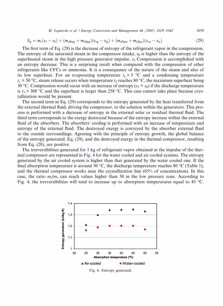
Sg ¼ mrðs5 � s8Þ þ ðmefhpg þ meflpgÞðsog � sigÞ þ ðmefhpa þ meflpaÞðsoa � siaÞ ð29Þ
The first term of Eq. (29) is the decrease of entropy of the refrigerant vapor in the compression.The entropy of the saturated steam in the compressor intake, s8 is higher than the entropy of thesuperheated steam in the high pressure generator impulse, s5 Compression is accomplished withan entropy decrease. This is a surprising result when compared with the compression of otherrefrigerants like CFCs or ammonia. It is a consequence of the nature of the steam and also ofits low superheat. For an evaporating temperature te = 5 �C and a condensing temperaturetc = 50 �C, steam release occurs when temperature t5 reaches 80 �C, the maximum superheat being30 �C. Compression would occur with an increase of entropy (s5 > s8) if the discharge temperatureis t5 > 308 �C and the superheat is larger than 258 �C. This case cannot take place because crys-tallization would be present.
The second term in Eq. (29) corresponds to the entropy generated by the heat transferred fromthe external thermal fluid, driving the compressor, to the solution within the generators. This pro-cess is performed with a decrease of entropy in the external solar or residual thermal fluid. Thethird term corresponds to the exergy destroyed because of the entropy increase within the externalfluid of the absorbers. The absorbers� cooling is performed with an increase of temperature andentropy of the external fluid. The destroyed exergy is conveyed by the absorber external fluidto the outside surroundings. Agreeing with the principle of entropy growth, the global balanceof the entropy generated, Eq. (29), and the destroyed exergy in the thermal compressor, resultingfrom Eq. (28), are positive.
The irreversibilities generated for 1 kg of refrigerant vapor obtained at the impulse of the ther-mal compressor are represented in Fig. 4 for the water cooled and air cooled systems. The entropygenerated by the air cooled system is higher than that generated by the water cooled one. If thefinal absorption temperature is around 50 �C, the discharge temperature reaches 80 �C (Table 1),and the thermal compressor works near the crystallization line (65% of concentration). In thiscase, the ratio ms/mr can reach values higher than 30 in the low pressure zone. According toFig. 4, the irreversibilities will tend to increase up to absorption temperatures equal to 45 �C.
Fig. 4. Entropy generated.

Fig. 5. Exergy destroyed.
1040 M. Izquierdo et al. / Energy Conversion and Management 46 (2005) 1029–1042
From this point, the irreversibilities are lower because the increase in generation temperature issmaller, aiming to avoid crystallization (Table 1).
Fig. 5 shows the exergy destroyed as a function of the absorption temperature for the watercooled and air cooled systems. Similarly, the exergy destroyed by the air cooled system is higherthan that destroyed by the water cooled one. The difference between the exergy destroyed (and theentropy generated) by the water cooled and the air cooled modes increases as the absorption tem-perature increases. For an absorption temperature equal to 50 �C, the air cooled mode generates14% more entropy and destroys 14% more exergy than the water cooled one.
3.7. Exergetic efficiency
The exergetic efficiency can be calculated as the ratio between the net exergy produced by thethermal compressor and the input exergy to the generators:
Fig. 6. Exergetic efficiency.
M. Izquierdo et al. / Energy Conversion and Management 46 (2005) 1029–1042 1041
gex ¼Eo
Ei
ð30Þ
The input exergy to the thermal compressor (neglecting the exergy supplied by the pumps) is theexergy transferred by the solar or residual external fluid:
Ei ¼ ðmefhpg þ meflpgÞðhig � hogÞ � ðmefhpg þ meflpgÞT 0ðsig � sogÞ ð31Þ
whereas the net exergy produced (exergy difference of the streams in the points 5 and 8), is givenby
Eo ¼ mrðh5 � h0Þ � mrT 0ðs5 � s0Þ � mrðh8 � h0Þ þ mrT 0ðs8 � s0Þ ð32Þ
Fig. 6 shows the exergetic efficiencies as a function of the absorption temperature for the doublestage cycle considered in the present study and the single and double effect cycles analyzed byIzquierdo et al. [1].
4. Conclusions
A double stage LiBr–H2O absorption cycle evaporating at 5 �C and fed by low temperatureheat coming from residual energy sources or flat plate solar collectors has been studied. The fol-lowing conclusions have been extracted:
• For condensation temperatures up to 50 �C, the double stage LiBr–H2O absorption cycle maybe operated with heat from flat plate solar collectors or residual sources without crystallizationproblems. About 80 �C of generation temperature are required in the double stage absorptionmachine when the condensation temperature reaches 50 �C, obtaining a COP equal to 0.37 inthe theoretical cycle.
• Irreversibilities generated by the double stage thermal compressor will tend to increase with theabsorption temperature up to 45 �C. The maximum value corresponds to 1.35 kJkg�1 K�1.From this point, they tend to decrease because of the increase in generation temperature (Table1), and as result, the concentration increase of the solution is smaller than for lower absorptiontemperatures, aiming to avoid crystallization.
• The entropy generated and the exergy destroyed by the air cooled system are higher than theentropy generated and the exergy destroyed by the water cooled one. The difference betweenthe values increases as the absorption temperature increases. For an absorption temperatureequal to 50 �C, the air cooled mode generates 14% more entropy and destroys 14% more exergythan the water cooled one.
• The exergetic efficiency of the double stage cycle considered is lower than that of the single anddouble effect cycles because it works with heat at lower temperature. The double stage systemhas about 22% less exergetic efficiency than the single effect one and 32% less exergetic efficiencythan the double effect one.

1042 M. Izquierdo et al. / Energy Conversion and Management 46 (2005) 1029–1042
Acknowledgement
The authors wish to express their gratitude to the Ministerio de Ciencia y Tecnologıa of Spainfor the financial support of this research through the project DPI-2002-02439.
References
[1] Izquierdo M, de Vega M, Lecuona A, Rodrıguez P. Compressors driven by thermal solar energy: entropy
generated, exergy destroyed and exergetic efficiency. Solar Energy 2002;72:363–75.
[2] Sumathy K, Huang ZC, Li ZF. Solar absorption cooling with low grade heat source: a strategy of development in
south China. Solar Energy 2002;72:155–65.
[3] Bisio G. Thermodynamic analysis of the main devices for thermal energy upgrading. Energy Conv Mgmt
1998;39(3-4):229–42.
[4] Hernandez F, Izquierdo M. The natural gas-absorption method system as alternative to the electric power–
mechanical compression system in Spain. Energy Conv Mgmt 1993;34(8):663–76.
[5] Lamp P, Ziegler F. European research on solar-assisted air conditioning. Int J Refrigerat 1998;21:89–99.
[6] Izquierdo M, Venegas M, Rodrıguez P, Lecuona A. Crystallization as a limit to develop solar air-cooled LiBr–
H2O absorption systems using low-grade heat. Solar Energy Mater. Solar Cells 2004;81(2):205–16.
[7] Arzoz D, Venegas M, Izquierdo M, Rodrıguez P. Solar absorption refrigeration cycle using LiNO3–NH3 solution
and flat plate collectors. In: Proc. 7th Int. Sorption Heat Pump Conf.; 2002. p. 101–6.
[8] Venegas M, Izquierdo M, de Vega M, Lecuona A. Thermodynamic study of multistage absorption cycles using low
temperature heat. Int J Energy Res 2002;26:775–91.
[9] Medrano M, Bourouis M, Coronas A. Double-lift absorption refrigeration cycles driven by low-temperature heat
sources using organic fluid mixtures as working pairs. Appl Energy 2001;68:173–85.
[10] Schweigler C, Demmel S, Ziegler F. Single-effect/double lift chiller: operational experience and prospect. In: Proc.
6th Int. Sorption Heat Pump Conf.; 1999. p. 533–9.
[11] Lamp P, Schweigler C, Ziegler F. Opportunities for sorption cooling using low grade heat. Appl Thermal Eng
1998;18:755–64.
[12] Ziegler F, Riesch P. A review with regard to energetic efficiency. Heat Recovery Syst CHP 1993;13:147–59.
[13] Kim D, Machielsen C. Evaluation of air-cooled solar absorption cooling systems. In: Proc. 7th Int. Sorption Heat
Pump Conf.; 2002. p. 117–22.
[14] Adewusi SA, Zubair SM. Second law based thermodynamic analysis of ammonia–water absorption systems.
Energy Conv Mgmt 2004;45(15-16):2355–69.
[15] Talbi MM, Agnew B. Exergy analysis: an absorption refrigerator using lithium bromide and water as the working
fluids. Appl Thermal Eng 2000;20(7):619–30.
[16] Meunier F, Kaushik SC, Neveu P, Poyelle F. A comparative thermodynamic study of sorption systems: second law
analysis. Int J Refrigerat 1996;19(6):414–41.
[17] Chua HT, Gordon JM, Ng KC, Han Q. Entropy production analysis and experimental confirmation of absorption
systems. Int J Refrigerat 1997;20(3):179–90.
[18] Bejan A, Tsatsaronis G, Moran M. Thermal Design and Optimization. John Wiley; 1996.


![Water binding energies of [Pb(amino acid-H)H2O]+ complexes determined by blackbody infrared radiative dissociation](https://static.fdokumen.com/doc/165x107/633c09c15bb2e4f8210c2aa4/water-binding-energies-of-pbamino-acid-hh2o-complexes-determined-by-blackbody.jpg)